Embed Size (px)
Citation preview

1
Government of India
Operation and Maintenance Manual
for Rural Water Supplies
March, 2011
Ministry of Rural Development
Department of Drinking Water and Sanitation

2
ACKNOWLEDGMENTS
This O&M Manual has been prepared by the Department of Drinking Water and Sanitation, Ministry of Rural Development, Government of India and the Water and Sanitation Program of World Bank.
The preparation team was Mr. T.M. Vijay Bhaskar (Joint Secretary) and Dr. K Mazumdar, (Deputy Adviser) from other officials, experts of the Department of Drinking Water and Sanitation, and Dr. Nicholas Pilgrim (Water and Sanitation Specialist) and Mr. Anand Jalakam (Consultant) from the Water and Sanitation Program.
Peer review was provided by, Mr. Satya Prakash Kuril (CE, UP Jal Nigam), Mr. Dharampal Singh Beniwal (CE, RWS, Govt. of Haryana), Shri Dinesh Chand (Joint Advisor, CPHEEO, MoUD), and Mr. D. Rajasekhar (Deputy Advisor, DDWS), Dr. Aidan Cronin (WASH Specialist, UNICEF).
References used in the preparation of the Manual include:
• Manual on Operation and Maintenance of Water Supply Systems, CPHEEO, 2005 • Management of operation and maintenance in rural drinking water supply and sanitation:
A resource training package, IRC, WHO, WSSCC, 1993 • A Handbook for Gram Panchayats to Help Them Plan, Implement, Operate, Maintain and
Manage Drinking Water Security, DDWS and WSP, 2010 • Water Safety Plans for Rural Water Supply in India, Policy Issues and Institutional
Arrangements, WSP, 2010 • Community Water Supply: The Handpump Option, UNDP-World Bank, 1987 • Grass Root Level Worker Training Package on Operation and Maintenance of
Handpumps: Trainers Guide, RGNDWM, 1995 • Trainers Guide: Community Based Handpump Maintenance India Mark II and India
Mark III (VLOM) Watsan Committee Members Training, GoI, 1995
Designed and illustrations by:
Date: March 2011

3
FOREWORD
Much progress has been made in providing water supply facilities in rural India. By 2009, India had reached almost universal coverage for more than 850 million people in 1.6 million habitations. Given the scale of the challenge, this is a remarkable achievement. However, services have been slipping. About one half of habitations face challenges associated with source sustainability, water quality or operation and maintenance.
Under the new National Rural Drinking Water Programme (NRDWP, 2009) and the Strategic Plan 2010-2022, the Department of Drinking Water and Sanitation has set out a framework for planning, implementation and management of drinking water schemes to ensure drinking water security, institutional and financial support, and capacity building. The Strategic Plan 2011-22 prepared by the Department proposes to set an ambitious target of coverage of 55 percent households with piped water supply by 2017, and 90 percent households by 2022. It also anticipates that the Twelfth Plan (2012-2017) will emphasise provision of higher service levels of drinking water supplies in rural areas to achieve improved service delivery.
At the same time, it is recognized that many households in rural India still rely on basic infrastructure such as handpumps, dug wells and springs etc with chronic problems of water quality due to poor sanitation and hygiene. Establishing behavior change to ensure open-defecation free villages remains the first step towards provision of good safe drinking water. These communities require interim strategies on the road towards piped water supply.
In 2010, the Department of Drinking Water Supply and Sanitation released the Handbook for Gram Panchayats to Help Them Plan, Implement, Operate, Maintain and Manage Drinking Water Security. This Operation and Maintenance Manual complements the GP Handbook by providing further technical and managerial information on the process and content through which village level water supply schemes are operated and maintained to ensure improved and sustainable service delivery. It takes into account the current aspirations and challenges facing the sector, and builds on the framework already set out in the NRDWP and Strategic Plan 2011-2022.
Secretary
Department of Drinking Water and Sanitation Government of India

4
Contents
Introduction to Operation and Maintenance ................................................................................... 6
What is O&M? ............................................................................................................................ 6
How can a village improve its O&M? ........................................................................................ 6
What are the different types of Rural Water Supply Scheme? ....................................................... 8
Dug wells .................................................................................................................................. 12
O&M activities for a dug well .............................................................................................. 12
O&M resources for a dug well.............................................................................................. 13
Handpumps ............................................................................................................................... 13
O&M activities for a handpump ........................................................................................... 15
Disassembly, inspection and reassembly of the handpump .................................................. 15
O&M resources for a handpumps ......................................................................................... 17
Local springs, streams or ponds with gravity fed piped systems .............................................. 19
O&M activities for gravity fed piped systems ...................................................................... 20
O&M resources for gravity fed piped systems ..................................................................... 20
Mechanised borewell or surface pump with piped systems ...................................................... 21
O&M activities for mechanized borewell ............................................................................. 21
O&M resources for mechanized borehole ............................................................................ 21
Surface water based piped system with water treatment .......................................................... 22
O&M activities for slow sand filter ...................................................................................... 25
O&M resources for mechanized borehole ............................................................................ 26
Key Principles for Piped Water Systems ....................................... Error! Bookmark not defined.
Sources of water ........................................................................................................................ 22
Transmission of water ............................................................................................................... 23
Water treatment plant ................................................................................................................ 24
Disinfection ............................................................................................................................... 27
Reservoirs including service reservoirs .................................................................................... 29
Distribution system ................................................................................................................... 31
Drinking water quality monitoring and surveillance ................................................................ 33
Operation and maintenance of pumping machinery ................................................................. 33
Water meters ............................................................................................................................. 35
Billing and Collection ............................................................................................................... 36
Water audit and leakage control ............................................................................................... 37
Energy audit and conservation of energy .................................................................................. 37

5
Planning and Implementing Improved Operation and Maintenance .............................................. 8
TEMPLATE 1 – TECHNICAL AND FINANCIAL SURVEY ................................................. 8
TEMPLATE 2 – WATER SAFETY PLAN ............................................................................. 18
TEMPLATE 3 – OPERATING PLAN..................................................................................... 44
TEMPLATE 4 – SERVICE IMPROVEMENT PLAN ............................................................ 50
TEMPLATE 5: PERFORMANCE INDICATORS ................................................................. 53
Monitoring Progress and Performance ......................................................................................... 54
Monitoring, Audit and Reporting ............................................................................................. 55
Benchmarking ........................................................................................................................... 55
6
Introduction to Operation and Maintenance
What is O&M?
“Operation refers to timely and daily operation of the components of a Water Supply system such as headworks, treatment plant, machinery and equipment, conveying mains, service reservoirs and distribution system etc. effectively by various technical personnel, which is a routine function.”
“Maintenance is defined as the art of keeping the structures, plants, machinery and equipment and other facilities in an optimum working order. Maintenance includes preventive maintenance or corrective maintenance, mechanical adjustments, repairs, corrective action and planned maintenance.”
However, replacements, correction of defects etc. are considered as actions excluded from preventive maintenance.
Manual on Operation and Maintenance of Water Supply Systems, CPHEEO, 2005
How can a village improve its O&M?
Efficient and effective operation depends upon sound village water supply strategies made up of (a) water safety plans to ensure good quality water, (b) standard operating procedures including who will do what and when, and to identify associated annual expenses and revenues; and (c) service improvement plans to set out future investments to ensure improved, sustainable service delivery.
Water Safety Plans shift the focus from end-of-pipe testing to improved operational management, with water quality testing used to verify outcomes. They provide a means of prioritizing improvement programmes based on health outcomes. Most importantly, water safety plans address bacteriological contamination which is the biggest water quality related threat to public health, especially infant mortality.
A water safety plan is developed by surveying the water supply system from source to storage/treatment to distribution to household (also known as a sanitary survey). This helps to identify risks of contamination and corresponding operational control measures to reduce those risks. The controls have to be monitored to check that they are working, specifying how often the check should be carried out, and identifying who is responsible for checking. If a control is deemed to have failed remedial action should be taken.
Standard operating procedures are essential to identify what local operators should do in terms of routine operation and maintenance related to water sources, storage and treatment units, and distribution systems including connections; and for annual budgets of operating expenses and income, and annual surplus/deficit. Someone with good experience and analytical skills would be needed to train operators and assist them when problems arise.
Often the tasks required can overwhelm a local operator who has only basic skills and limited experience, but by providing basic orientation in terms of what to do and when, the operator can quickly gain hands on experience and build confidence to do the job well. Likewise, the operator’s fees and incentives can be made transparent and this also helps to improve their performance.

7
Service improvement plans are important to define management improvements, service delivery improvements and actions to improve accounts, billing and revenue collection. The benefits and costs need to be considered and priorities set (such as immediate, this year or next year).
In this manual, simple one or two page tables (templates) have been prepared to help villages achieve improved and sustainable service delivery (O&M):
• A technical / financial survey (including the sanitary survey).
• A water safety plan template to identify the main risks of contamination and common operational control measures and remedial actions.
• An operating plan template, which sets out the basic tasks of the operator, as well as how to calculate maintenance and staff costs and water revenues and the gap between costs and revenues.
• A service improvement plan template, which identifies typical problems that rural schemes encounter and provides guidance on prioritizing operational and infrastructure remedies (further technical support is needed to design and cost the remedies).
• Basic performance indicators which can be used by the Gram Panchayat, Block Resource Centre and District Water and Sanitation Mission to monitor implementation and performance.
These simple templates allow villages to assess the condition of their assets, the true costs of operations, and their current performance, and to identify operational and infrastructure remedies and how they propose to finance these.
The templates can also be used to guide development of training modules for local operators, field facilitators, Gram Panchayats, and Block Resource Centre and District Water and Sanitation Mission staff.

8
Planning and Implementing Improved Operation and Maintenance
TEMPLATE 1 – TECHNICAL AND FINANCIAL SURVEY
District: Block: GP: Name / designation of Surveyor(s): Date of Survey: BASIC INFORMATION 1. Name of GPU
2. Total current population in the GPU / number of households (include source of data)
3. Number of Villages/Wards/Habitations in the GPU
4. Names of Villages/Wards/Habitations in the GPU

9
SCHEME INFORMATION 1. Name of Village/Ward/Habitation being
surveyed
2. Population/number of households
3. Name used to identify water supply scheme being surveyed
4. Description of the source(s) (e.g., tubewell, protected spring, stream, pond, canal etc.)
5. Estimated production capacity of the source(s) in cubic meters per day
6. Describe any problems with source sustainability, e.g., during summer/winter
7. Source infrastructure condition of intake/headworks
8. Treatment system / Sedimentation tank capacity, age and condition
9. Storage tank capacity, age and condition
10. Distribution pipes size, length, type of pipe, age, condition
11. Average number of supply interruptions per month, e.g., source blockage, major pipe breaks, etc.
12. Number of connections (if possible also provide an estimate of how
much water is used in cubic meters per month per connection)
1. Domestic 2. Schools 3. Health clinics 4. Anganwadis 5. Commercial/Industrial 6. Other
13. Average time to collect 20 liters of water
(minutes or hours)

10
14. Average hours of supply per day to domestic connections (identify problems)
15. Pressure at connections (indicate if low, good, high)
16. Mention any ongoing or proposed projects
17. Key observations and problems identified during the survey
18. Possible solutions identified during the survey
19. Feed back from the beneficiaries

11
Please prepare a diagram of the scheme that has been surveyed (see example below)
Transmission
Reservoir tank
Houses C
Source & headworks Treatment
system / Sedimentation tank

12
What are the different types of Rural Water Supply Schemes?
There are five common water source and system options:
1. Dug wells
2. Handpumps
3. Local springs, streams or ponds with gravity fed piped systems
4. Mechanised borewell or surface pump with piped systems
5. Surface water based piped system with water treatment
These different types of rural water supply schemes are described below in terms of basic details, O&M activities, and O&M resources. Most of the information has been extracted from the resource training package Management of Operation and Maintenance in Rural Drinking Water Supply and Sanitation (IRC, WHO and WSSCC, 1993).
Dug wells
Dug wells vary in size, shape, depth, lining and the method of raising water. Typically water is raised by a simple bucket and rope passing over a pulley. The well may have a diameter of about 1.5 meters. It may be lined for example with concrete. A headwall and cover should be built to prevent spilt water, rainfall runoff, debris, people and animals from entering or falling inside. A concrete apron is critical to prevent polluted water seeping back down the sides of the well, provide a platform for users to sand on, and direct water away from the well to drainage channels. The well can be fenced.
O&M activities for a dug well The daily O&M activities should include:
Dug wells / Handpumps
Local spring / stream / pond source(s)
Mechanised borewell(s) / surface pump(s)
Sedimentation tank(s)
Storage tank(s)
Distribution pipes
Community standposts or household connections
Household hygiene and sanitation
Surface water source
Water treatment

13
• Check for any debris in the well by regular visual inspection • Clean the concrete apron • Clear the drains • Check that the gate is closed • Check the condition of the rope, pulley, bucket and fence by regular visual inspection • Report problems to the VWSC
Weekly activities should include:
• Lubricate the pulley as needed with grease • Record the water level with a rope scale and report to the VWSC
Monthly activities should include:
• Replace the bucket and other parts as needed • Collect community contributions or user charges and deposit with the VWSC • Check the concrete apron and well seal for cracks and repair with cement mortar as
needed
Annual activities should include:
• Dewater the well and clean the bottom • Inspect the well walls and lining and repair as needed • Check the water level and deepen the well as needed • Check the support posts for the pulley and repair as needed
O&M resources for a dug well Unskilled labour (VWSC) is required for daily tasks and for collecting user charges. Semi-skilled labour (well caretaker) is needed to carry out weekly and monthly O&M tasks; a private fitter may be needed to repair the well pulley. Skilled labour (mason) is needed to work with the caretaker on yearly O&M tasks and to repair the concrete apron and support posts for the pulley.
Materials and equipment include the bucket and rope, fencing, support posts, brush, digging and hand tools, cement, pulley and pulley shaft and bearings, and masonry tools to be provided to the caretakers by the VWSC.
Finances would be from the VWSC/GP for labour, replacement parts and maintenance equipment.
Handpumps
Boreholes may be fitted with a variety of pumps. The India Mark II (Figure 1) and the India Mark III (Village Level Operation and Maintenance) (Figure 2) are the most common handpumps implemented by the Public Health Engineers.
The India Mark II is suitable for a depth of up to 50 meters. The pump body parts are extremely durable over the years. The pump achieves high discharges in the range 25-45 meters. The skills and tools needed to service a Mark II make it unsuitable for village maintenance, and requires help from qualified mechanics. While the Mark II has been around for ages and is used in almost every corner of the world, the VLOM advantage in the Mark III means that every time the cylinder components need replacement or maintenance, only the valve assemblies can be pulled out without taking out the riser mains. In many villages where the resources are scarce,

14
this can often mean the difference between the pump working and or being broken down for a long time. At the same time, the cost of riser pipes is nearly double in Mark 3.
Figure 1: India Mark II Figure 2: Cylinder Assembly of India Mark III Hand Pump
With all handpumps the borehole is sealed to prevent the ingress of surface water polluting the borehole. A platform is critical so that water drains away to a soakpit/leachpit at least three meters from the borehole. The handpump should be mounted on top of the borehole so that dirty water cannot pass back into the borehole. The platform must be designed so that it is convenient to use by women and children. The handpump is bolted to the concrete platform.

15
The notes below are drawn from the Trainers Guide for Grass Root Level Worker Training Package on Operation and Maintenance of Handpumps (RGNDWM, 1995).
O&M activities for a handpump The daily O&M activities should include:
• Clean the hand pump and spout pipe by hand • Check all the flange nuts and bolts and tighten as needed • Make sure the hand pump is firm on its base, and fix as needed with the help of a mason
Weekly activities should include:
• Check the axle bolt and tighten as needed • Make sure the lock nut is tight • Make sure the handpump is firm on its base • Check the flange bolts fastening the water chamber to the pedestal are tight • Testing water quality using a Field Test Kit
Monthly activities should include:
• Tighten the handle axle nut and lock nut • Check for loose or missing flange bolts and nuts and tighten as needed • Open the cover and clean inside the pump • Check the chain anchor bolt for proper position and tighten if needed • Look for rusty patches, clean with a wire brush and apply anticorrosive paint • Find out whether the handpump base is loose and arrange for repair of the foundation as
needed
Annual activities should include the following checks, and repairs made:
• Discharge is satisfactory • Handle is shaky • Guide bush is excessively worn out • Chain is worn out • Roller chain guide is excessively worn out
Disassembly, inspection and reassembly of the handpump Disassembly of the handpump may be required from time to time if major problems are faced:
• Loose pump head cover bolt • Remove inspection cover from head assembly • Insert chain coupling supporting tool • Lift the handle to the top position and disconnect chain from handle by removing the
“nyloc” nut and bolt (i.e., nylon insert lock nut) • Take out handle axle; while removing use the handle axle punch to protect the axle thread
and remove the handle from the head assembly • Remove flange bolts from the head assembly • Remove head assembly from the water tank • Place the connecting rod vice on to the water chamber top flange and tighten vice against
connecting rod and allow the head assembly to sit on the connecting rod vice

16
• Disconnect the chain assembly from connecting rod • Support connecting rod with connecting rod lifter, loosen connecting rod vice and
remove; gently lower connecting rod to sit on check valve; remove connecting rod lifter • Loose water tank nuts and bolts and remove water tank bottom flange bolts • Lift water tank by using tank pipe lifter and lifting spanners • Fit self locking clamp and remove water tank • Join plunger assembly to check valve by turning the rod lifter in clock wise direction • To take out water from the pipe, remove the rod lifter; join the rod lifting adaptor to the
connecting rod; place head assembly over water tank and fix handle to the lifter • Remove water from riser pipe by pushing down handle suddenly • Life handle upwards slowly and disconnect connecting rod lifting adapter and take out
head assembly • Tighten the connecting rod lifter to the connecting rod and lift the connecting rod and fix
the connecting rod vice • Hold the connecting rod, slowly loosen the rod vice and lift the connecting rod; tighten
the vice and repeat the process until it is possible to remove the connecting rod; repeat the process until the last connecting rod with plunger and check valve is pulled out
• Separate the check valve from the plunger • Unscrew the plunger from the check valve • Remove all the parts of the check valve and clean them
Inspection for reassembly covers the following:
• Check the water tank for leakage or damage • Wash and clean all parts with a mixture of kerosene oil and water • The stand assembly should be on a perfect level – check with a spirit level • Check the coupler for broken threads • Check flanges and spout pipe for cracks and leakage • Check the handle axle, bearings and chain; apply grease to the bearings and chain
Reassembly is as follows:
• Ensure parts are clean and dry, and moving parts are lubricated with oil and grease • Check ‘O’ ring and cup seal and replace as needed • Remove cover of casing pipe for fixing stand assembly • Place stand assembly over casing pipe and make sure that it is vertical and check level of
flange by spirit level • Fix water tank assembly on the stand flange by tightening the nuts and bolts • Join the check valve and plunger • Connect the plunger to the connecting rod • Insert the plunger assembly connected with the check valve in the riser pipe and connect
the riser coupler to the water tank • Insert the lower end of the connecting rod in the riser pipe, and place the connecting rod
over the water tank and fix it to the vice • Join the connecting rod pieces as per the requirement and insert in the riser pipe • Remove the connecting rod vice from the water tank by holding the top end of the
connecting rod

17
• Fix the connecting rod lifter to the top end of the connecting rod and rotate in the direction of the arrow so as to separate the check valve from the plunger and ensure that it reaches the bottom plate
• Make a mark by hack saw on the connecting rod at the level of the water tank • Lift the connecting rod assembly, fix the connecting rod vice and tighten the connecting
rod • Cut the connecting rod as per the marking after removing the connecting rod lifter • Smoothen with the help of a file the cut surface of the connecting rod • Make necessary threads on the top most end of the connecting rod • Fix the middle flange on the top of the water tank and ensure that all four corners
coincide • Tighten the check nut at the top of the connecting rod • Screw the chain on to the connecting rod • Place the chain coupling supporting tool on the middle flange and remove the rod vice • Place the middle flange and set flanges with water tank • Place head assembly over the middle flange and tighten by spanner • Place handle assembly and insert the handle axle by handle axle punch • Lift the handle for fixing chain and tighten chain anchor bolt and nyloc nut fully (i.e.,
nylon insert lock nut); remove chain coupler supporting tool by lowering the handle • Lift handle up and apply grease on the chain • Lower down the handle and fix inspection cover and tighten the cover bolt fully by the
crank spanner
O&M resources for a handpump A semi-skilled caretaker is required for daily, weekly and monthly O&M tasks, and to collect user charges. Skilled labour (qualified handpump mechanic, mason) is needed to work with the caretaker on yearly preventive maintenance, disassembly/reassembly of the handpump, and to repair the concrete apron and drains.
Materials and equipment include sand and cement, fencing, brushes for cleaning, spare parts for pump repairs, tools for maintenance and repairs, and pipes for the rising main.
Finances would typically be from the VWSC/GP consisting of user charges, GP resources or Government funds for labour, materials and spare parts.
18
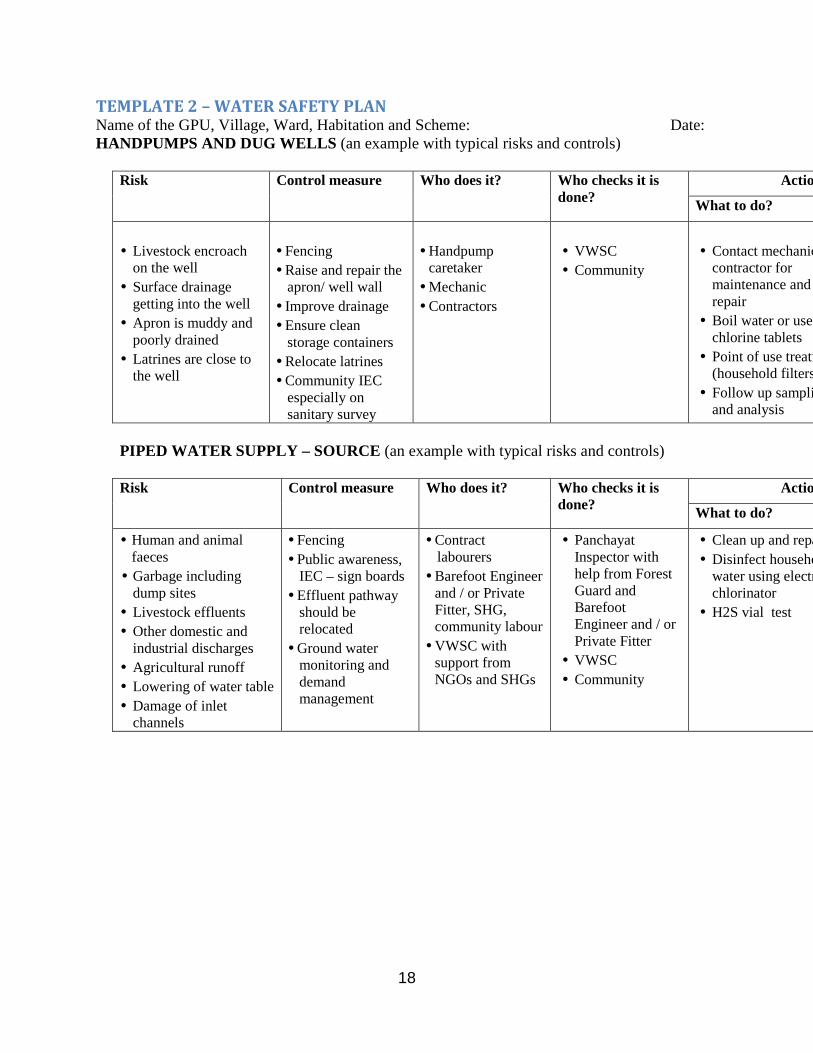
TEMPLATE 2 – WATER SAFETY PLAN Name of the GPU, Village, Ward, Habitation and Scheme: Date: HANDPUMPS AND DUG WELLS (an example with typical risks and controls)
Risk Control measure Who does it? Who checks it is
done? Action if control fails
What to do?
• Livestock encroach
on the well • Surface drainage
getting into the well • Apron is muddy and
poorly drained • Latrines are close to
the well
• Fencing • Raise and repair the
apron/ well wall • Improve drainage • Ensure clean
storage containers • Relocate latrines • Community IEC
especially on sanitary survey
• Handpump
caretaker • Mechanic • Contractors
• VWSC • Community
• Contact mechanic or
contractor for maintenance and repair
• Boil water or use chlorine tablets
• Point of use treatment (household filters)
• Follow up sampling and analysis
PIPED WATER SUPPLY – SOURCE (an example with typical risks and controls) Risk Control measure Who does it? Who checks it is
done? Action if control fails
What to do?
• Human and animal faeces
• Garbage including dump sites
• Livestock effluents • Other domestic and
industrial discharges • Agricultural runoff • Lowering of water table • Damage of inlet
channels
• Fencing • Public awareness,
IEC – sign boards • Effluent pathway
should be relocated
• Ground water monitoring and demand management
• Contract labourers • Barefoot Engineer
and / or Private Fitter, SHG, community labour
• VWSC with support from NGOs and SHGs
• Panchayat Inspector with help from Forest Guard and Barefoot Engineer and / or Private Fitter
• VWSC • Community
• Clean up and repair• Disinfect household
water using electrochlorinator
• H2S vial test

19
Local springs, streams or ponds with gravity fed piped systems
People in hilly, rural areas often depend entirely on spring sources, gravity flow, and piped water supply with tap connections (Figure 3).
Figure 3: Typical Gravity Fed Piped System
Gravity fed piped systems include the following components: a storage tank with inlet (from the source), outlet (to standposts or household connections) and washout, and overflow pipe; distribution pipeline with valves and valve boxes often of PVC or PE for buried sections and galvanized iron for exposed sections and house connections; standposts made up from galvanized iron delivery pipe possibly encased in a concrete pillar, with a tap, and with a concrete platform to direct dirty water to a drain; and a drain and soakaway at least three meters from the standpost.
Field observations indicate the following types of problems are common: spring and stream sources are not protected and are contaminated by animal fecal matter and garbage; sedimentation and storage tanks are not covered or properly cleaned; in rural growth centers tapping by private pipelines is common; treatment is non-existent and, in particular, chlorination is not practiced; pipes are leaking, badly repaired, and are often surrounded by animal fecal

20
matter and garbage; household storage and handling is unsafe and hand washing with soap is not practiced.
O&M activities for gravity fed piped systems The daily O&M activities at each standpost should include:
• Check if the tap works • Check the flow of water • Attend to any dripping tap • Attend to any leaking valve • Clean the standpost platform, drain and surroundings • Inspect the standpost structure, platform and drain – repair any cracks in the plaster with
cement mortar
Weekly activities at the tank should include:
• Check there are no leaks, the overflow is in good order, valves are in the correct position, and water is flowing into the reservoir at the required rate
• Walk the distribution pipeline, check for leaks, look for disturbed sections of pipeline, check valves are working, inspect valve boxes – repair as needed including pipes and areas of erosion around pipes
Monthly activities should include:
• Collect user charges and deposit with the VWSC
Annual activities should include:
• Drain the reservoir, clean and disinfect the tank • Plaster and repair cracks in the walls and floor of the tank • Check that valves are working and repair or replace as needed • Open the washout to flush pipes • In the dry season remove soakaway stones, clean the soakaway pit and stones before
replacing them
O&M resources for gravity fed piped systems A semi-skilled standpost caretaker is required to carry out daily inspections at standposts and assist in repairing pipeline leaks and erosion control. The VWSC should collect user fees and purchase spares as needed, and keep a record of leak detection and repair. The standpost caretaker would also carry out daily and weekly activities on the distribution system. Skilled labour (pipe fitters, masons) are needed to repair pipe leaks and the tank or standpost infrastructure.
Materials and equipment include sand and cement, stones for erosion control, brushes for cleaning, tools for maintenance and repairs, PVC, PE or GI pipes, and spares for taps and valves.
Finances would typically be from the user charges, GP resources or Government funds for labour, materials and spare parts.

21
Mechanised borewell or surface pump with piped systems
A typical mini water supply system based on a mechanized borewell would be similar to a gravity fed piped system except that the source is a borewell with a submersible pump and motor. Motor service intervals are usually specified in terms of running hours. Therefore, service intervals expressed in days, weeks and months will have to be based on the average number of hours run per day for each installation.
Boreholes should be fully cased and screened and the top of the borehole sealed to prevent ingress of surface water polluting the borehole. The rising main exits at the top of the borehole through a purpose made cap to prevent contamination of the borehole by surface water and debris. An isolation valve and non-return valve are fitted on a horizontal section of the delivery pipe, adjacent to the borewell. Typically, the pump house is located next to the borehole, and houses the control panel for operation of the electric pump.
O&M activities for mechanized borewell The daily O&M activities of the pump operator should include:
• Operate pump starter • Open isolation valve • Check reading on ammeter is normal – stop pump if electric motor is drawing too much
current and report problems • Confirm water is being delivered • Check for leaks in the rising main • Continue to check voltmeter and ammeter readings during the day
Weekly activities at the tank should include:
• Clean the pump house • Testing water quality using a Field Test Kit
Monthly activities should include:
• Billing and collection, and deposit with the VWSC
Annual activities should include:
• Remove the pump and rising main from the well and inspect • Check pipe threads and re-cut corroded or damaged threads • Replace badly corroded pipes • Inspect electric cables and check insulation between cables • Record servicing and maintenance in log book • De-silt borehole if required • Check screen and clear as needed
O&M resources for mechanized borewell Semi skilled labour (pump operator) is required for pump operation and billing and collection. Skilled labour is required for pump and motor servicing and maintenance.

22
Materials and equipment include pipes for the rising main, tools for maintenance and repair, oil for the motor, spare parts for the motor and electrical control panel.
Finances would typically be from the household paying water charges, GP or VWSC resources and Government funds.
Surface water based piped system with water treatment
More complex piped water systems are covered in this chapter including sources of water, intake, transmission lines, water treatment plants and headworks, etc.
Sources of water
Discussion of surface water sources and intakes (inlet channels) and transmission of bulk water is described in detail in the CPHEEO O&M manual chapters 3 and 4, including inspection and O&M of dams, O&M of intakes, and O&M of borewells.
Dams are constructed to create artificial lakes or reservoirs. A dam conserves the surplus water brought down by a river during the periods when the supply exceeds the current demand, for utilization later on during the periods when demand outstrips the natural flow of the river.
An Intake/inlet channel is a device or structure placed in a surface water source to permit withdrawal of water from this source and its discharge into an intake conduit through which it will flow into the water works system.
Well failure may be due to inadequate design, faulty construction and operation, lack of timely maintenance and repair and failures due to mechanical and chemical agents and adverse aquifer conditions. The main causes for source failure are categorised as under:
• Incorrect design: for instance use of incorrect size of screen and gravel pack, wrong pin pointing of well site resulting in interference.
• Poor construction e.g. the bore may not be vertical; the joints may be leaky, wrong placement of well screen, non-uniform slots of screen, improper construction of cement slurry seal to prevent inflow from Saline aquifer.
• Corrosion of screens due to chemical action of water resulting in rupture of screens. • Faulty operation e.g. over pumping, poor maintenance. • Adverse aquifer conditions resulting in lowering of the water table and deterioration of
water quality. • Mechanical failure e.g. falling of foreign objects including the pumping assembly and its
components. • Incrustations due to chemical action of water. • Inadequate development of wells.
Tube wells should run in such a way that the pumping water level should always remain above the level of the well screen. Over pumping will expose the well screen, which may result in incrustation and corrosion. Over pumping results in excessive draw down which may cause differential hydrostatic pressures, leading to rupture of the well screen. Further details regarding causes of failure of wells and well problems and their suggested solutions are tabulated in the CPHEEO O&M manual chapter 3, pp 53-54.

23
Transmission of water
The overall objective of a transmission system is to deliver raw water from the source to the treatment plants and transmit treated water from treatment plants to the storage reservoirs for onward supply into distribution networks.
Water levels in the sumps from which the water is being pumped are measured using flow meters. Critical points are selected in the transmission system for monitoring of pressures by installation of pressure recorders and gauges. In the pumping systems, whenever water pressures in the pumping station drops below the designed system pressure, the operators are alerted to search for possible leaks in the pumping system. Similarly at the receiving end, if the required water levels are not building up at the storage reservoir, it indicates that the required quantity is either not pumped or there may be leakages enroute. At times whenever the maximum levels in the receiving reservoirs are reached the pumps will have to be stopped or the outlet valves of the reservoir have to be opened.
The maintenance schedule for transmission mains should include:
• Develop and conduct a surveillance programme for locating and repairing leaks in pipelines, pipe joints and valves, and servicing of valves and maintenance of valve chambers,
• Arrange for flushing, cleaning and disinfecting the mains, • Establish repair procedures for standard services and with provision for continuous
training of the team members, • Procure appropriate machinery, equipment and tools for repair of leaks and replacement
of pipes and valves, • Allocate suitable transport, tools and equipment to each maintenance team, • Establish time, labour and material requirement and output expected, time required and
other standards for each maintenance task, and • Arrange for monitoring the productivity of each team.
Leakage
Leakage of water in the transmission system occurs by way of leakage from pipes, joints and fittings, reservoirs and overflows of reservoirs and sumps. The objective of the leakage control programme is to reduce to a minimum the time that elapses between the occurrence of a leak and its repair.
Flushing is done to clean the transmission lines by removing impurities or sediment that may be present in the pipe; this is particularly essential in the case of transmission lines carrying raw water.
A minimum free chlorine residual of about 0.2 mg/l at the receiving reservoir of a transmission system is often maintained to ensure that contamination is destroyed by the chlorine.
Contaminated water through cross connections of water supply lines with sewers and drains is a problem prevailing widely. Regular survey along the alignment of transmission system has to be undertaken to identify potential areas likely to be affected by cross connections and back-flow.
A detailed list of records to be maintained on the transmission system is given in the CPHEEO O&M manual on page 70, and a check list on page 72. Sample records to be maintained include:

24
• Updated transmission system map and location of flow meters and pressure gauges, • Record of flow meter readings at upstream and downstream ends of the transmission
system, • Record of water levels of the reservoirs at both upstream and downstream ends of the
transmission system, • Pressure readings of the transmission system pipelines, • Age of pipes/quality of pipes* , • Persistent leak points, • Status of bulk meters – functional, • Residual chlorine levels at the receiving and transmitting ends of the transmission
system, • Identify the bacteriological quality of the water sampled from the reservoirs linked to the
transmission system, • Record on when the pipeline leaks were repaired or pipes changed and the cost of
materials and labour cost thereof, • Record on valve and valve chamber repair/replacement and the cost of materials and
labour cost thereof, • Record on man-hours spent on routine operations in the transmission system in the
previous year and the cost thereof, including outside agencies, and • Record on when the exposed piping was last painted and the cost of materials and labour
cost thereof.
* The various types of pipes used in water supply projects are:- (i) Cast Iron (CI) (ii) Mild Steel (MS) (iii)Reinforced Cement Concrete (RCC) (iv) Pre Stressed Concrete (PSC) (v) Asbestos Cement (AC) (vi) Poly Ethylene (PE)
a. Low density (LDPE) b. High density (HDPE)
(vii) Rigid PVC (UPVC) (viii) Ductile Iron (DI) (ix) Fiber Glass Reinforced Plastic (FGRP) (x) Glass Reinforced Plastic (GRP) (xi) Fiber Glass Reinforced Plastic (FRP)
Age and quality of pipes should be as per the respective State Policy and BIS specification.
Water treatment plant
Some of the common treatment processes used in the past includes plain sedimentation, Slow Sand filtration, and Rapid Sand filtration with coagulation-flocculation units as essential pretreatment units.

25
Roughing filters are used, under certain circumstances, as pretreatment units for the conventional filters. The treatment processes may need pretreatment like pre-chlorination and aeration prior to conventional treatment.
A detailed description of the operation and maintenance for slow sand filters, rapid sand filters and roughing filters is given in the CPHEEO O&M manual chapter 5. In the case of slow sand filters this includes the tasks of operation, filter cleaning, resanding, and augmentation of capacity.
Slow sand filter
Slow sand filter is most widely used in rural water supply schemes and is an effective, low cost system of water treatment if operated and managed correctly. It is normally one component in a treatment process which may involve preliminary settlement of solids and / or roughing filters and post chlorination. A treatment plant operator, or caretaker, may have a number of responsibilities in addition to the operation and maintenance of slow sand filters. Caretaker responsibilities may extend from the initial source of water to eventual distribution.
Typically there will be two rectangular slow sand filters operating in parallel. During maintenance one filter is kept operating. The filter also comprises pipe work, under-drains, graded gravel to support the filter sand and the filter sand. The filter is operated by a combination of valves: inlet, inlet drainage, back-filling, emptying, filter regulation, clear water drainage, and distribution. A flow indicator is used for checking the flow rate. The turbidity of the inlet water is checked to ensure the water is of an acceptable turbidity to prevent rapid blocking of the filter. Turbidity is also measured at the outlet to check the filter is functioning properly. The supervising manager carries out daily bacteriological tests on the filtered water.
O&M activities for slow sand filter The daily O&M activities should include:
• Check the rate of filtration on the flow indicator – adjust the rate of filtration as needed by turning the filtered water valve
• Check the water level in the filter – adjust the inlet vale as needed to maintain a constant water level
• Remove scum and floating material by further opening the inlet valve for short time • Check the water level in the clear well • Sample and check water turbidity – if the inflow turbidity is too high close the intake; if
the outflow turbidity is too high report to the supervisor • Testing water quality • Complete the log book
Weekly activities at the tank should include:
• Clean the water treatment plant site
Monthly activities should include:

26
• Shut down the filter unit – remove scum and floating material; brush the filter walls; close the inlet, filtered water and distribution valves; drain water to 20 cm below the sand level; increase the filtration rate in the other filter to 0.2 m/h
• Clean the drained down filter bed – wash boots and equipment before use; scrape upper 2-3 cm in narrow strips and remove scrapings from filter; check, and service, exposed inlet and drain valves; remove cleaning equipment and level sand surface; check and record depth of sand bed; adjust inlet box to the new sand level
• Re-start the filter – open the recharge valve; check sand surface and level as needed; when water is 20 cm above the sand, open the inlet valve; open the filtered water valve and stop when filtration rate reaches 0.02 m/h; open waste valve for outflow water to flow to waste; open filtered water valve to increase filtration rate every hour by 0.02 m/h until a rate of 0.1 m/h is reached; adjust and check flow daily until safe to drink; close waste valve and open distribution valve to pass filtered water into the supply; decrease filtration rate of other filter to 0.1 m/h
• Wash the filter scrapings and store the clean sand
Annual activities should include:
• Check if filter is water tight: close all valves and fill filter box from inlet valve until it overflows – close valve; leave for 24 hours and check if water level reduces; if filter box leaks, report for repair; open filtered water valve to fill outlet chamber and when full, close valve; leave for 24 hours and check if water level reduces; if chamber leaks, report for repair; open drain valve to empty filter; clean the clear well in the outlet chamber; restart filter as per the month clean
Every two years, activities should include:
• Re-sand the filter units – clean the filter as in a monthly filter clean; open drain valve to empty water from the sand bed; remove strip of old sand to one side; place new clean sand on top of exposed gravel, and level; place old sand on top of the new sand to the correct depth of 0.8 m in total, and level the surface; continue in strips until filter is resanded; adjust inlet box to new sand level
• Re-start the filter as per the monthly clean
Irregular checks will include:
• Checks on the functioning of the plant by supervising manager including turbidity tests with a turbidity meter, and bacteriological tests on the filtered water
O&M resources for slow sand filter Unskilled labour required for re-sanding. Semi skilled labour (caretakers) is required for plant operation. Skilled labour (supervising manger) is required for supervision.
Materials and equipment include sand, basic tools, valve replacement and spares, flow indicator, turbidity apparatus, bacteriological testing equipment.
Finances would typically be from the household paying water charges, GP/VWSC resources and Government funds.

27
Specific Treatment Technologies Arsenic & Fluoride removal methods: There are several treatment methods available for the removal of arsenic in waters for potable use. They include: - (a) Chemical precipitation (b) Adsorption (c) Membrane processes Iron Removal Plant (IRP) The most widely used IRP in the rural area for removing excess iron from drinking water source is based on oxidation, sedimentation and filtration. Brackishness Removal Plant Membrane based desalination plants popularly known as Reverse Osmosis (RO) plants. Based on the above process each of the manufacturers has designed the treatment units with variable components and design parameters. It is important that O&M manual is obtained from the manufacturer and a guide booklet for field level operators prepared with simple language for their easy understanding.
In all such treatment plants the telephone number of the operator should be painted on the building/machinery for contacting them during breakdowns.
Disinfection
Why should we disinfect drinking water?
Drinking water is disinfected to kill bacteria, viruses and parasites, which may be in the water and may cause illness and disease. Many different diseases are spread by contaminated drinking water, including Campylobacter, cholera, amoebic dysentery, Giardia (beaver fever) and Cryptosporidia. These organisms usually get into drinking water supplies when source waters such as lakes or streams, community water supply pipes, or storage reservoirs are contaminated by animal wastes or human sewage.
In general, surface waters such as lakes and streams are more likely to contain disease-causing organisms than groundwater. Deep wells are safer than shallow wells. In fact, shallow dug wells are often as contaminated as lakes or streams.
When should we disinfect drinking water? We should disinfect your drinking water if:
• Your community has been issued a boil water advisory; • You are using water directly from a stream, lake or shallow well; • Lab tests of your water show that it contains "faecal coliforms"; • A flood, earthquake or other disaster has disrupted your community water supply;

28
• You are travelling in an area where water is not well treated; or • You have a weakened immune system, in which case you should disinfect all of your
drinking water.
Disinfecting rural water supply schemes Chlorine treatment is relatively cheap, readily available and provides prolonged disinfecting action. Though chlorine is generally used for disinfecting potable water it can also be used as an algaecide. Pre-chlorination has specific toxic effect and causes death and disintegration of some of the algae. It also assists in removal of algae by coagulation and sedimentation. It prevents growth of algae on basin walls and destroys slime organisms on filter sand thus prolonging filter run and facilitating filter washing. Dosage: Effective chlorine dose should be such that sufficient chlorine is there to react with organic matter, ammonia, iron, manganese and other reducing substances in water and at the same time leave sufficient chlorine to act as algaecide. Dose required for this purpose may be over 5mg/l. With chlorine treatment essential oils present in algae are liberated which may lead to development of odour and color and taste. Occasionally these oils as well as organic matter of dead algae may combine with chlorine to form intensified odour and taste. In such cases break point - chlorination is required. Post chlorination dose can be adjusted to obtain minimum 0.2mg/l residual chlorine in potable water at consumer end.
Other Disinfectant
The other chemical based disinfectants generally in used as disinfectant in water supply schemes are ionized silver coating, halogens, ozone, potassium permanganate and hydrogen peroxide. A number of commercially available alternative processes, such as membrane processes, are able to remove bacteria, viruses and protozoa as well as a range of chemical contaminants. These are coming into use but generally only on a small scale. It may be possible to operate these processes with no chemical disinfection or at least to reduce the amount of chemicals used for final disinfection. Alternatives to chemical disinfection, such as UV irradiation, are also being used for disinfection of drinking water. Such ‘non-conventional’ processes and disinfection methods could in principle be used to replace, or at least greatly reduce, the use of chemical disinfection of drinking water.
UV irradiation and membrane processes are potentially suitable alternatives to chemical disinfection. UV is capable of inactivating bacteria and viruses, and possibly protozoan parasites. A range of pressure-driven membrane processes – microfiltration, ultra-filtration, nano-filtration and reverse osmosis in order of decreasing pore size – are also capable of disinfection as well as removal of chemical contaminants, depending on pore size. The use of membrane processes would avoid the formation of disinfection by-products and would reduce the concentrations of other undesirable chemicals, giving a net benefit in terms of toxicological issues. The main microbiological concerns with membrane systems are ensuring the integrity of the membrane and monitoring the efficiency of micro-organism removal; with conventional chlorination the residual chlorine concentration is easily monitored and provides reassurance that disinfection has been carried out effectively.

29
These methods are described in the CPHEEO manual chapter 6.
Reservoirs including service reservoirs
The main function of Reservoirs and Service Reservoirs (SR) is to cater for daily demands and especially peak demands of water. Operators/managers must be concerned with the amount of water in the storage reservoir and the corresponding water levels at particular times of the day. Procedures for operating the Service Reservoir will depend upon the design of its storage capacity and on the water demand.
Service Reservoirs have to be operated as per the design requirements. Normally the service reservoirs are constructed to supply water during periods of high water demand and hence the SRs are filled in low water demand periods. At times pumps may be used only for filling the SR before the next supply timing or can be used also during supply hours to maintain the levels in the SR. Old SR should be evaluated from time to time to ascertain its structural stability and take corrective measures.
Small changes in the distribution system such as pipeline extensions or the addition of few more connections will not require additional storage requirement. Major system changes such as addition of larger size of main pipelines and increase in large number of connections may require additional storage.
Routine inspection is the best way to determine when a tank requires maintenance and cleaning. A visual inspection can be made from the roof manhole with water level lowered to about half full or less. Alternatively a detailed inspection can be made after draining the tank and then cleaning or washing. Best time of the year to take up cleaning of SRs is during the period of lowest water consumption.
The following activities are normally involved in cleaning of a tank/SR:
• Make alternate arrangement for water supply to consumers served by the SR, • Close the inlet line before commencing cleaning of SR, • Draw the water from the SR till 200-300 mm water is left in the SR, • Close the outlet valve so that no water will be used while the tank is being cleaned, • Collect sample of water and silt/mud accumulated in the Tank and get the biological
analysis and for presence of snails and worms. If snails and worms are found find the source and eliminate it,
• Drain and dispose off the remaining water and silt, • Wash the interior of tank walls and floor with water hose and brushes, • Inspect the interior of walls and ceiling of tank for signs of peeling off or deterioration, • Apply disinfectant (Supernatant of Bleaching powder) to the walls and floor before start
of filling the tank/SR, and • Frequency of cleaning of SR depends on the extent of silting, development of bio films
and results from water quality monitoring.
Identification of the valves as to their intended purpose such as inlet, outlet, scour, bye-pass etc. and their direction of opening are to be prominently marked. The operator/manager shall ensure

30
that all valves in a SR are in good working condition and are operated as per the schedule for such operations.
All valves should be inspected and operated regularly:
• The manager shall specify frequency of inspection, • A small amount of penetrating oil is poured down the spindle to lubricate packing gland
and soften the packing, • Valve spindles that develop leaks on turning should be repacked, • Rust and sediment in the valve is removed by shutting the disc hard in the seat, then
opening about a quarter way and closing tightly several times; the increased velocity usually flushes the obstructions away, and
• Valve chambers of the SR also require maintenance to ensure that the interiors of chambers are not silted up and also ensure that the covers are in good condition and are in position.
• Alignment, stability and leakage of the duck-foot pipe of SR should be checked regularly.
Water from all SRs should be regularly sampled especially once, before and after monsoon to determine the quality of water that enters and leaves the SR. Sampling data can help in setting up periodic cleaning of SR. Indicators that help to decide when the tank is due for cleaning is turbidity, excessive colour, taste and odour.
The following operation and maintenance records should be kept:
Operation:
• Water levels in the SRs (for all compartments) at hourly intervals, • Time and relevant operation of control valves with time of opening and closure or
throttling position of the valves, • Hourly flow meter readings both on the inlets and outlets, • Hourly residual chlorine readings of inflow water and outflow water, and • The man-hours spent on routine operations at the SR in previous year and the cost
thereof.
Maintenance:
• When the gland ropes of the valves at the SR were changed, • When the spares of the valves were changed, • When the manhole covers were changed/replaced, • When the water level indicator was repaired or replaced, • When the reservoir was last cleaned, • When the out-fall drain for scour and overflow was last cleaned, • When the ladder was changed, • When the structure of the reservoir was last repaired to attend to structural defects or
arrest leakage, • When the reservoir was last painted, • When the piping at the reservoir was last painted, and • Total cost of repairs and replacements at the SR in previous year along with break up of
material cost and labour cost with amount spent on outside agencies for repairs and replacements.

31
Distribution system
The overall objective of a distribution system is to deliver wholesome water to the consumer at adequate residual pressure in sufficient quantity at convenient points and achieve continuity and maximum coverage at affordable cost.
Normally, the operations are intended to maintain the required supply and pressure throughout the distribution system. Critical points are selected in a given distribution system for monitoring of pressures by installation of pressure recorders and gauges.
Key issues to manage include: low pressure at supply points, leakage of water, unauthorized connections, extension of area of distribution system, age of the system, lack of records, and mapping and inventory of pipes and fittings.
A continuous evaluation of the hydraulic conditions of the water supply system can be done by the O&M personnel after obtaining the data on water volumes and flows at various points in the system, the water pressures and levels in the reservoirs and comparing with expected performance. This evaluation shall lead to identification of operational problems and/ or system faults. Depending on the type of problems actions have to be initiated to ensure that the system functions as per the requirement.
Maintenance of a continuous positive pressure at all times (during supply timings) to all consumers is the main concern of O&M. Negative pressures can cause contamination of water supplies especially in intermittent supplies. Very high pressures may damage the pipelines and valves, which can be corrected with pressure reducing valves. Complaints from consumers about low pressures have to be promptly investigated if necessary by measuring pressures with pressure gauges. Low pressures may be under the following circumstances:
• Purposefully or accidentally a line valve is left closed or partly closed or blockage due to any material causing loss of pressure,
• Too high velocities in small pipelines, • Low water levels in SR, and • Failure of pumps/booster pumps (either due to power failure or mechanical failure)
feeding the system directly.
The operator has the responsibility of ensuring that the water supplied to the consumer is of an appropriate quality. To achieve this objective it is necessary that the physical, chemical and bacteriological tests are carried out at frequent intervals. Samples should be taken at different points on each occasion to enable overall assessment.
The objective of developing a programme for managing in times of shortage of water is to reduce the excessive use of water particularly when the source is limited due to adverse seasonal conditions. Basically it involves that a water conservation policy is developed and implemented among water consumers. The following activities can be considered while formulating such a water management project:
• Installation of accurate bulk and domestic water meters and establishment of a realistic tariff structure to encourage water conservation and prevent wastage of water,
• Enforcement of restrictions on use of treated water for watering lawns, cooling, construction, washing of vehicles etc.,

32
• Encouragement and/or enforcement of the reuse of treated industrial effluents and municipal wastewater, and
• Development and implementation of public education programmes to encourage water conservation.
The following activities should be included in the maintenance schedule for the distribution system:
• Set up maintenance schedules for servicing valves and maintenance of valve chambers, repairing pipe breaks, flushing and cleaning pipelines, leakage detection and repair, managing cross connections with sewers and drains, chlorine residual testing, and establishing rules for customer connections,
• Formation of maintenance teams for each type of service with provision for continuous training,
• Establishment of repair procedures for standard services, • Specification of appropriate tools, • Allocation of suitable transport, tools and equipment to each team, • Establishment of time, labour and material requirement and output expected; time
required and other standards for each maintenance task, and • Monitoring the productivity of each team.
A minimum chlorine residual of about 0.2 mg/l at the selected monitoring point is often maintained to ensure that even a little contamination is destroyed by the chlorine. Hence, absence of residual chlorine could indicate potential presence of heavy contamination. If routine checks at a monitoring point are carried out, required chlorine residuals and any sudden absence of residual chlorine should alert the operating staff to take up prompt investigation. Immediate steps to be taken are:
• Re-testing for residual chlorine, • Checking chlorination equipment, • Searching for source of contamination, which has caused the increased chlorine demand,
and • Immediate stoppage of supplies from the contaminated pipelines.
The CPHEEO O&M manual chapter 8 provides a list of records to be maintained and a check list for the distribution system. Sample records to be maintained are given below for guidance:
• Updated system map, • Pressure and flow readings at selected monitoring points, • Persistent low pressure or negative pressure areas, • Age of pipes/quality of pipes, • Pipelines to be replaced, • Presence of corrosive water in the system, • Water budget for each zone served by one SR, • Number of connections given, • Number of meters out of order, • Quantity measured at outlet of reservoir, • Quantity distributed/measured or billed,

33
• Source of leaks and persistent leak points, • Status of bulk meters - functioning or not, • Status of consumer meters, • Facilities for repairs of consumer meters, • Number of unauthorised connections, • Residual chlorine levels at the pre-selected monitoring points, • Bacteriological quality of the water sampling points, • Persistent areas where residual chlorine is absent/where bacteriological samples are
unwholesome, • Record on carrying out repairs on the following works and its cost:
- The pipe line leaks or replacement of pipes. - Change of gland ropes of the valves in distribution system. - Replacement of parts. - Replacement of manhole covers.
• Record on man hours spent on routine operations in the distribution system in the previous year and the cost thereof,
• Record on total cost of repairs and replacements in previous year along with breakup of material cost and labour cost with amount spent on outside agencies for repairs and replacements,
• Record on when the exposed piping was last painted and the cost of materials and labour cost thereof, and
• Record on the unserved areas - extension of pipelines- need for interconnections.
Drinking water quality monitoring and surveillance
With respect to drinking water quality monitoring and surveillance, the CPHEEO O&M manual chapter 9 provides useful advice on water related diseases and preventative strategies (see p 198), and remedial and preventive measures for protection of water supplies (see p 209).
Operation and maintenance of pumping machinery
Pumping machinery and pumping stations are very important components in a water supply system. Pumping machinery is subjected to wear, tear, erosion and corrosion due to their nature of functioning and therefore is vulnerable to failures. Generally more number of failures or interruptions in water supply are attributed to pumping machinery than any other component. Therefore, correct operation and timely maintenance and upkeep of pumping stations and pumping machinery are of vital importance to ensure uninterrupted water supply. Sudden failures can be avoided by timely inspection, follow up actions on observations of inspection and planned periodical maintenance. Downtime can be reduced by maintaining inventory of fast moving spare parts. Efficiency of pumping machinery reduces due to normal wear and tear. Timely action for restoration of efficiency can keep energy bill within reasonable optimum limit. Proper record keeping is also very important.
Preventive maintenance for pumping machinery is very specific depending on the pumps, motors and other electrical and mechanical equipment being used. Some guidance is provided in the CPHEEO O&M manual chapter 11 for daily, monthly, quarterly and annual inspections and maintenance for pumps (see pp 235) and motors (see pp 240), but in general it will be necessary

34
to follow the manufacturer or supplier’s recommendations for the schedule and procedures to follow. A log book should be maintained which should cover the following items.
• Timings when the pumps are started, operated and stopped during 24 hours, • Voltage in all three phases, • Current drawn by each pump-motor set and total current drawn at the installation, • Frequency, • Readings of vacuum and pressure gauges, • Motor winding temperature, • Bearing temperature for pump and motor, • Water level in intake/sump, • Flowmeter reading, • Daily PF over 24 hours duration, and • Any specific problem or event in the pumping installation or pumping system e.g. burst
in pipeline, tripping or fault, power failure.
The CPHEEO O&M manual chapter 11 also provides guidance for trouble shooting for different types of pumps and motors (see pp 255).
SCADA (Supervisory control and data acquisition)
Supervisory control and data acquisition (SCADA) systems provide control functionality and alarms at rural water supply scheme sites which in many cases are very remote. These systems were often used to solve single problems such as reducing power cost, or improving control of a particularly complex operation. The installation of SCADA has subsequently been seen as a means to satisfy a variety of increasing pressures such as consumer demands, regulatory requirements, and to also satisfy the need to reduce operational costs. The deployment of SCADA systems has been extended to cover large rural water supply schemes and has been found very effective.
An important challenge to the commercial success of the organisation is to harness the data collection power of the SCADA systems to provide a wealth of operational information to all levels of the organization. Past systems that have been installed in some of the water treatment plants have failed to meet expectations regarding data availability. This has primarily been attributed to difficulties associated with merging traditional engineering and new IT methodology, and a lack of system openness in data interconnectivity and communications.
Remote Terminal Units (RTU)
A Remote Terminal Unit (RTU) is a microprocessor-controlled electronic device that interfaces objects in the physical world to a SCADA (supervisory control and data acquisition system) by transmitting telemetry data to the system and/or altering the state of connected objects based on control messages received from the system. Modern RTUs are usually capable of executing simple programs autonomously without involving the host computers of SCADA system to simplify deployment, and to provide redundancy for safety reasons. An RTU in a

35
modern water management system will typically have code to modify its behavior when physical override switches on the RTU are toggled during maintenance by maintenance personnel. This is done for safety reasons; a miscommunication between the system operators and the maintenance personnel could cause system operators to mistakenly enable power to a water pump when it is being replaced, for example.
Water meters
A water meter is a scientific instrument for accurate measurement of quantity of water distributed to the consumers. It also fulfils the need to know accurately the water produced and distributed.
The testing and calibration of a water meter is essential before putting it into use as it is a statutory requirement. It is also essential to test it periodically in order to ascertain its performance as during the course of meter working it is likely that its accuracy of measurement may deteriorate beyond acceptable limits.
The water meters are mechanical/electromagnetic devices, which normally deteriorate in performance over time. The fact that a meter does not show outward signs of any damage and has a register that appears to be turning does not mean that the meter is performing in a satisfactory way. It is necessary to ascertain the following preventive cares for water meter after proper installation.
Preventive maintenance:
• Proper handling, storage and transportation of water meters, • To clean the dirt box or strainer wherever installed, • To replace the gaskets, if any, • To clean the chamber in which the meter is installed and keep free from flooding, and
seepage, and • To remove the meter for further internal repair/replacement if it does not show correct
reading pattern.
Breakdown maintenance requires the replacement of broken glass, lid and fallen wiper wherever provided. These are the only basic breakdowns observed during periodical inspection. If a meter is found not working, then it shall be removed immediately and sent to a meter service workshop.
Metering household connections in some districts like Dakshina Kannada in Karnataka has led to equitable distribution of water and financially self-sustainable water supply schemes. In 2010, out of 203 numbers of GPs in the district, 128 GPs adopted meters for household connections coupled with volumetric-based tariff and computerized billing and collection.
The CPHEEO O&M manual chapter 12 provides guidance on trouble shooting of water meters (see p 289).

36
Billing and Collection
The revenue management system is an important aspect of any Water supply System as it governs the financial aspect. Besides fixing a tariff structure, billing and collection of revenue play an important part.
The water charges to be fixed by the utility take into account the ability of the system to meet the expenditure on the following heads. (i.e.)
• Operating Cost (excluding establishment cost), • Establishment Cost, • Depreciation, • Debt Services and Doubtful Charges, and • Asset replacement fund.
The various categories of consumers are:
• Domestic, • Commercial (Business entities, Hotels, Industries etc.), • Government Authorities, • Partly Commercial, and • Bulk Consumers.
Among the five categories, the domestic consumers are the privileged class of people in terms of supply of water and collection of taxes mainly because they use water for their healthy existence. The other categories of consumers largely use water while carrying out commercial/ business activities.
The methods of levying water charges can be any one or more of the following:
A. Metered System:
• Actual consumption of water, and • Minimum fixed charge.
B. Non-Metered System:
• Fixed charge per house per month, • Fixed charge per family per month, • Fixed charges per connection per month • Fixed charge per tap per month, and • Percentage of rateable value of the property.
The various stages in the Cycle of Water Billing Process are:
• Data gathering (Meter reading in case of metered billing), • Generation of bill based on this data, • Distribution of bill to consumer, • Payment of the Bill by the Consumer, • Sending the receipt details to billing section, and • Related accounting.

37
In Malkapur, Satara Dt, Maharashtra, 24x7 water supply with fully automatic readable metered system provides an opportunity to reduce manpower costs of meter reading. With introduction of telescopic rates which require the higher rate for higher consumption the wastage of water is grossly reduced. The service works on no loss basis. Tariff rates are determined accordingly.
Water audit and leakage control
Water Audit of a water supply scheme can be defined as the assessment of the capacity of total water produced by the operator and the actual quantity of water distributed throughout the area of service of the operator, thus leading to an estimation of the losses. Otherwise known as non-revenue water, unaccounted-for water (UFW), is the expression used for the difference between the quantity of water produced and the quantity of water which is billed or accounted for.
The major activity during the overall water audit will be bulk meter installation at those points on the distribution network where water enters the system. It is expected that bulk meters will be required at the following locations:
• All major system supply points, • All tubewells which supply the system directly, and • Major transfer mains which are expressly required for audit.
At distribution centres, the most appropriate meter position is on the outlet pipe from the service reservoir.
A distribution system comprises of service reservoirs, distribution mains and distribution lines including consumer service lines, connections viz. metered, unmetered (flat rate), public stand posts, and illegal connections. The area of the village is divided into service zones. Water audit of the distribution system consists of:
• Monitoring of flow of water from the distribution point into the distribution system zones,
• Consumer sampling, • Estimating metered use by consumers, and • Estimating losses in the distribution pipe line network including consumer service lines.
The major activities in the leak detection work in the distribution system are preliminary data collection and planning, pipe location and survey, assessment of pressure and flows, locating the leaks, and assessment of leakage.
There are a number of different techniques for repairing pipes that leak. These techniques depend on the severity of leak, type of break in the pipe, the condition of the pipe and the pipe material. The methods include a repair clamp to cover the defect, a cut out of the defective section of pipe work/fittings and replacement with a short length of pipe, and relay/renewal of the whole or section of the pipe.
Energy audit and conservation of energy
The cost of energy is increasing day-by-day. Generally pumping installations consume huge amount of energy wherein proportion of energy cost can be as high as 40 to 70% of overall cost of operation and maintenance of water works. Need for conservation of energy, therefore cannot

38
be over emphasized. All possible steps need to be identified and adopted to conserve energy and reduce energy cost so that water tariff can be kept as low as possible and gap between high cost of production of water and price affordable by consumers can be reduced. For that Capacitors should be installed which is an electronic component which is used in a wide variety of circuit applications due to its ability to store charge.
In an electric power system, a load with a low power factor draws more current than a load with a high power factor for the same amount of useful power transferred. The higher currents increase the energy lost in the distribution system, and require larger wires and other equipment. Because of the costs of larger equipment and wasted energy, electrical utilities will usually charge a higher cost to customers where there is a low power factor. This issue needs to be monitored on a regular basis.
Energy audit as implied is auditing of billed energy consumption and how the energy is consumed by various units, and sub-units in the installation and whether there is any wastage due to poor efficiency, higher hydraulic or power losses etc. and identification of actions for remedy and correction. Some aspects of inefficiencies in energy use are:
• Energy consumption is higher than optimum value due to reduction in efficiency of pumps,
• Operating point of the pump is away from best efficiency point • Energy is wasted due to increase in head loss in pumping system e.g. clogging of strainer,
encrustation in column pipes, encrustation in pumping main, • Selection of uneconomical diameter of sluice valve, butterfly valve, reflux valve, column
pipe, drop pipe etc. in pumping installations, and • Energy wastage due to operation of electrical equipments at low voltage and/or low
power factor.
Economics
The Central 12th and 13th Finance Commissions have recommended separate grants to PRIs, which could be used to partly meet the operation and maintenance expenditure incurred by the PRIs on ensuring potable drinking water supply. 10% NRDWP fund will be allocated among States/UTs for O&M and States/UTs will make matching contribution, which along with funds provided under the Finance Commission’s recommendations as grants to PRIs will be used to meet the O&M expenditure on drinking water supply. It would be desirable to deposit such O&M contributions in a dedicated fund linked to the project operated by PRI itself.
All water supply schemes within the GP shall preferable be maintained by the Gram Panchayat. For multi –village or bulk water supply schemes the source, treatment plants, rising mains etc., can be maintained by PHED or the concerned agency whiles the distribution and other components are maintained by the GP.
In this regard the salient features of the Order issued by Government of Haryana regarding devolution of powers to Panchayati Raj Institutions and handing over of Drinking Water Supply Schemes (tubewell based) are given below for reference.

39
i. Only operation and maintenance of single village with single tubewell or upto two
tubewells be handed over to the Gram Panchayat concerned. ii. PHED would pay monthly amount of Rs. 7000/- to Gram Panchayat for single village
single tubewell scheme and Rs.10000/- for single village two tubewells scheme. This amount would cover payment of salary of staff, maintenance of tubewell (s) as well as maintenance of the distribution system. PHED would transfer the said amount to the account of the respective Gram Panchayats.
iii. Disinfectant material would be provided by the PHED, free of cost, but its proper usage and monitoring would be undertaken by the Panchayats and record maintained.
iv. Electricity charges to HBVN will be paid by PHED on actual basis. v. The maintenance of the distribution system and collection of revenue on account of private
water connections would be the responsibility of the Gram Panchayats. The savings arising, if any, out of funds provided by PHED for operation & maintenance and revenue collected by the Gram Panchayats could be utilized by them for upgradation/ improvement of the water supply scheme including the distribution network. The Gram Panchayat would also be allowed to sanction domestic water connections to the consumers. The Gram Panchayats would maintain a proper record of the revenue generated and expenditures incurred under various heads.
vi. In case of failure of any tubewell the replacement rectification thereof would be done by the PHED at Government expense.
vii. The major replacement of pipelines as well as laying of additional pipelines would also be done by the PHED at Govt. expense.
viii. The ownership of the assets of the Drinking Water Supply Schemes shall vest in the Gram Panchayats after the take over of the scheme by the GPs. The Gram Panchayats would be responsible for the operation and maintenance of the Drinking Water Supply Schemes and for all liabilities related thereto.
ix. PHED would provide technical guidance and expertise to the Gram Panchayats if specifically requested by them.
x. The operator to be engaged by the GP would preferably be ITI qualified. In case ITI qualified operator is not available, the candidate should atleast have 10+2 qualification with Science stream.
xi. The operator to be engaged should preferably belong to the same village and in case suitable candidate is not available, the same may be engaged from an adjoining (nearby) village.
xii. Proper record of release of water connections and collection of revenue would be maintained by the Panchayats.
xiii. As an incentive, the person engaged in release of private water connection, would be paid Rs. 50/- per connection.
xiv. Similarly, the amount equal to 15% of the total revenue collected would be paid to the person engaged in revenue collection.
xv. PHED would not engage any staff for the operation and maintenance of the Drinking Water Supply Schemes taken over by the Gram Panchayats under this proposal.
xvi. The record of water supply hours will be maintained as being done by PHED at present

40
xvii. The failure of tubewell due to chokage/damage of filter or any other structural failure of tubewell or ceasing of discharge on account of fall of water table will be reported by Panchayat to PHED immediately.
xviii. The Govt. reserves its right to take back the Drinking Water Supply Scheme whenever it is deemed fit in the Public interest.
Award Schemes
The “Nirmal Gram Puraskar”, the incentive award provided to achieve open defecation free environments in PRIs, has resulted in huge motivation amongst rural people; the award is taking the shape of a Campaign mode with the number of awardees increasing from a mere 40 Gram Panchayat in 2004-05 to about 2,809 Gram Panchayat in 2009-10. Similarly, to incentivize the Gram Panchayats to establish “drinking water security” at all times, the State Government should launch an award scheme for Gram Panchayats which attain 100% drinking water security with the water supply scheme totally managed by the PRI/VWSC with active involvement of the community in planning and implementation.
The suggested eligibility criteria for such an award may be as follows:
• In order to become eligible for the Puraskar, the concerned Gram Panchayat/Block/Zilla Panchayat must have received the Nirmal Gram Puraskar (NGP) to ensure that the chances of bacteriological contamination of drinking water sources are eliminated.
• A Gram Panchayat/Block/District would be eligible if it has achieved Drinking Water Security in terms of “access to safe and sustainable drinking water for all during the last 3 years”. i.e., meeting standards of access and usage, quantity, quality and reliability, and service provider responsiveness (see Template 5 Performance Indicators), with absence of incidence of any water borne diseases during the last 3 years (data to be obtained from nearest PHC).
• The VWSC or User Committee has to be in place in the Panchayat. Wherever the PRIs are not in place, the concerned Revenue village/Block/District Administration would be considered for the award till the time the PRIs are put into place.
• If in-situ treatment plants are used, there should be proper disposal of sludge/wastewater in an environment friendly manner.
Issues which should be confirmed before an award is made can include:
• Equity in access to drinking water to all social and income groups including vulnerable sections like SC/ST/OBC, disabled persons, widows, etc.
• Sanitary protection (a water safety plan) covering all drinking water sources and local catchments, treatment plants, distribution systems, and household practices.
• Preparation of a water balance though monitoring groundwater water levels for quantity and quality and rainfall, together with adaptation plans for different seasons depending on the water balance.
• Meeting the minimum 50% cost of O&M either through structured tariff plan, or proper utilization of GP, NRDWP and Finance Commission funds.
• Water quality testing of all drinking water sources and systems by the community using simple to use field test kits and confirming the same with district/other laboratories.
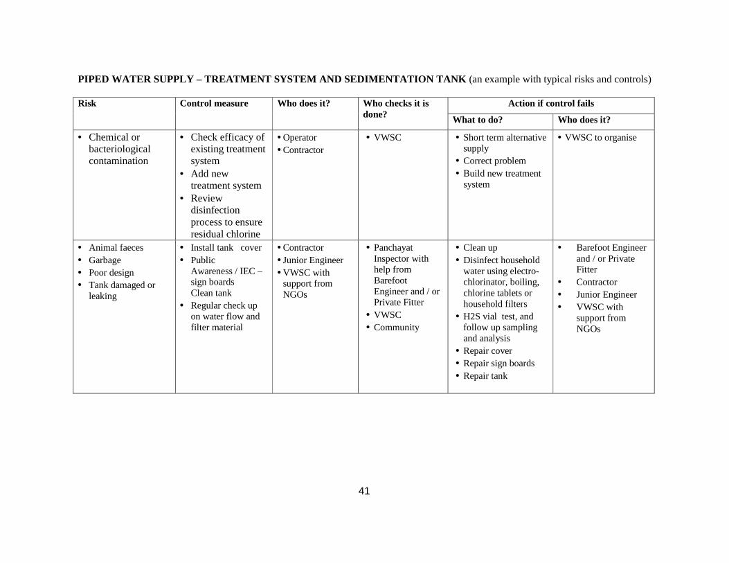
41
PIPED WATER SUPPLY – TREATMENT SYSTEM AND SEDIMENTA TION TANK (an example with typical risks and controls)
Risk Control measure Who does it? Who checks it is
done? Action if control fails
What to do? Who does it?
• Chemical or bacteriological contamination
• Check efficacy of existing treatment system
• Add new treatment system
• Review disinfection process to ensure residual chlorine
• Operator • Contractor
• VWSC • Short term alternative supply
• Correct problem • Build new treatment
system
• VWSC to organise
• Animal faeces • Garbage • Poor design • Tank damaged or
leaking
• Install tank cover • Public
Awareness / IEC – sign boards Clean tank
• Regular check up on water flow and filter material
• Contractor • Junior Engineer • VWSC with
support from NGOs
• Panchayat Inspector with help from Barefoot Engineer and / or Private Fitter
• VWSC • Community
• Clean up • Disinfect household
water using electro-chlorinator, boiling, chlorine tablets or household filters
• H2S vial test, and follow up sampling and analysis
• Repair cover • Repair sign boards • Repair tank
• Barefoot Engineer and / or Private Fitter
• Contractor • Junior Engineer • VWSC with
support from NGOs

42
PIPED WATER SUPPLY - STORAGE TANK (an example with typical risks and controls)
Risk Control measure Who does it? Who checks it is done?
Action if control fails
What to do? Who does it?
• Animal faeces • Garbage • Bathing and laundry • Tank damaged or
leaking • Private pipelines
connected at tank
• Install tank cover • Public awareness / IEC –
sign boards • Clean tank • Regular check up
on tank condition • Explore options to
disconnect private connections
• Contractor • Junior Engineer • VWSC with
support from NGOs
• Barefoot Engineer / Private Fitter
• Panchayat Inspector with help from Barefoot Engineer and / or Private Fitter
• VWSC • Community
• Clean up • Disinfect household
water using electro-chlorinator
• H2S vial test • Repair cover • Repair sign boards • Repair tank
• Barefoot Engineer and / or Private Fitter
• Contractor • Junior Engineer • VWSC with
support from NGOs

43
PIPED WATER SUPPLY - DISTRIBUTION PIPELINE (an example with typical risks and controls)
Risk Control measure Who? Who monitors? Action if control fails
What? Who?
• Animal faeces • Garbage • Effluents • Poorly laid pipelines
in public footpaths or drains
• Leaking pipes • Cross contamination
from sewers and drains
• Public Awareness / IEC
• Regular check up on pipes
• Protect pipes at risk from cross contamination
• Barefoot Engineer / Private Fitter
• Contractor • Junior Engineer • GP/VWSC with
or without support from NGOs
• Panchayat Inspector with help from Barefoot Engineer and / or Private Fitter
• VWSC • Community • Panchayat
• Clean up • Disinfect household
water using electro-chlorinator
• H2S vial test • Realignment of
pipelines • Repair of
leaking pipes
• ASHA (VWSC) • Barefoot Engineer
and / or Private Fitter
• Contractor • Junior Engineer • VWSC with
support from NGOs
HOUSEHOLD STORAGE AND PERSONAL HYGIENE (an example with typical risks and controls) Risk Control measure Who? Who monitors? Action if control fails
What? Who?
• Unclean storage container
• Absence of lid on storage container
• No ladle to remove water
• Public awareness / IEC
• Point of use treatment
• ASHA (VWSC) • NGOs • Teachers • Health workers • Anganwadi
workers • Self Help Groups
• VWSC • Sanitary
Inspector
• Disinfect household water using electro-chlorinator
• H2S vial test
• ASHA (VWSC) • NGOs
• No hand washing with soap
• Uncut nails
• Public awareness / IEC
• Empower women groups to advocate personal hygiene
• ASHA (VWSC) • NGOs • Teachers • Health workers • Anganwadi
workers • Self Help Groups
• VWSC • Sanitary
Inspector
• Disinfect household water using electro-chlorinator
• H2S vial test
• ASHA (VWSC) • NGOs

44
TEMPLATE 3 – OPERATING PLAN
The operating plan sets out the basic operating tasks as well as expenses, income and surplus/deficit. Table 1 – Operating functions Part of the System Key Operating Functions (what is to be done) How often? Who can help? Handpumps and dug wells
• People should be taught to use the pumps such that the handle does not hit the handpump
• Village caretakers should be able to recognize basic problems • GPs ought to have a contract with a qualified handpump mechanic
to inspect the pumps in all its villages on a regular schedule and carry out preventive maintenance and repairs
• •
Spring and intake / inlet channels headworks
• Inspection and O&M of dams • O&M of intake/headworks • Trouble shooting and O&M of borewells • Monitoring source availability during dry season1 • Monitoring source pollution • Implementing water source plan • Planning for new source to meet future demand
• •
Pumps • Conducting routine O&M - Clean the pump, motor and other accessories - Check coupling brushes, stuffing box, gland, etc. - Check for changes in sounds, temperature, vibrations, oil
leaks - Check for changes in voltage, current, vacuum gauge and
pressure gauge • Facility management (pump house) • Asset maintenance and spare parts • Flow and pressure monitoring • Monitoring energy consumption (energy audit)
• •
1 Also during the rainy season when floods and landslides are a problem

45
• Trouble shooting for pumps •
Transmission mains • Prepare/update transmission system map and asset register • O&M of bulk meters • Flow and pressure monitoring • Leak detection and repair • Flushing, cleaning and disinfection • Chlorine residual testing • Valve inspection and maintenance of valve chambers • Painting pipes • Monitoring productivity of maintenance teams
• •
Water treatment plants (SSF)
• Conducting routine O&M - Maintenance of raw water screens or roughing filters - Compliance monitoring for flow, pressure and quality - Filter cleaning - Resanding
• Facility ManagementAsset maintenance • Adjusting treatment process for changing quality of raw water • Monitoring chemical usage
• •
Storage and distribution pipeline
• Conducting routine O&M • Storage tank inspection, cleaning and paintingValve inspection
and maintenance of valve chambers • Compliance monitoring for water levels, flow, pressure and quality • Water audit • Leak detection and repair • Painting pipes • Managing cross connections with sewers and drains • Chlorine residual testing • Repairs, rehabilitation, expansion of networks • Monitoring productivity of maintenance teams
• •
Customer services • Installing new connections • Installing bulk and household meters • Meter testing and calibration, maintenance and replacement
• •

46
• Meter reading • Billing and collection • Customer complaints redressal, monitoring customer satisfaction • Debt management
Water Safety • Conducting a sanitary survey for risk assessment • Implementing the water safety plan • Monitoring water quality
• •
Connections • Monitoring misuse of water • Monitoring handpumps and community standposts to prevent
wastage • Maintaining clean aprons and drains • Monitoring household connections to promote equity • Monitoring unauthorized/illegal connections
• •
Operator’s Administration
• Depositing collections • Reporting to the VWSC
• •
VWSC’s administrative tasks
• Procurement including professional support as needed • Contract supervision • Monitoring of quality of work • Organising periodical water quality tests • New connections • Disconnections • Extensions • Debt collection • Payment of contractors, operator and handpump caretakers • Cash book keeping • Maintaining Stores register • Reporting to the GP • Securing finance for replacement of assets as per maintenance
schedule • Feed back from consumers
• •

47
Table 2 - Expenses Type of cost Cost component Cost (Rs./year) Electricity •••• Minimum demand charge
•••• Consumption charge •••• Tax
••••
Minor repairs • Spring intake / headworks • Pumps • Water treatment plants • Storage and distribution pipelines • Customer services • Water safety • Connections
•
Salaries and wages • Operator (manager) • Handpump caretakers • Pump operators • Bill collectors • Valvemen • Contract labour • Others
•
Consumables • Spares • Chemicals • Admin (stationary, transport, telephone, etc.) • Tools
•
Water quality • Lab tests • Training • For Operator
• For VWSC members •
IEC • Awareness generating activities •

48
Table 3 – Income Tariff and Budget Unit Value Number of domestic connections Number
Number of non domestic / commercial connections
Number
Monthly tariff for domestic connections Rs./month
Monthly tariff for non domestic / commercial connections
Rs./month
Other revenues, e.g., community standposts, institutions
Rs./month
Total amount billed per month
Rs./month
Total amount collected per month
Rs./month
Collection efficiency (= amount billed / amount collected)
%
Estimated income from water revenues Rs./year
Table 4 – Annual surplus / deficit Income and expenses Rs./year Total staff costs
Total maintenance costs
Estimated income from water revenues
Surplus/deficit

49

50
TEMPLATE 4 – SERVICE IMPROVEMENT PLAN
The service improvement plan sets out measures that need to be implemented to improve services. The measures include some which are just about better operational management and some which require investment. There are three levels of priority: immediate; this year; after this year. HANDPUMPS AND DUG WELLS Sample only – actual information will be specific to the GP/VWSC’s own proposal
Type of Service Improvement
Action proposed (the remedy) Why? (the benefit) Cost Timing (the priority)
Source conservation and protection
Refer to water source plan Water security • This year
Well repair and maintenance
Rehabilitate well or consider piped system
Ensure water security • As needed
Handpump operation and maintenance including fencing, apron and drainage Dug well wall
• Contract qualified mechanic for preventive maintenance
• Contractors • Training for caretaker • Training for users
Improved operation and maintenance (repair dug well wall, fence, raise and repair the handpump apron, improve drainage, ensure clean storage containers, relocate latrines)
• Immediate
Water Safety • Refer to water safety plan • Testing by field test kit/district/sub-
divisional laboratory
• Water quality and public health
� Immediate
Administrative tasks • Keeping ledgers for operational and financial records
• Public awareness / IEC activities
• Improved reporting and monitoring � This year

51
PIPED WATER SUPPLY SYSTEM Sample only – actual information will be specific to the GP/VWSC’s own proposal For more complex source intakes, pumping equipment and water treatment works technical assistance should be sought from qualified mechanics and electrical engineers from the PHED through the Block Resource Centre or from the designated Support Organisation.
Code Type of Service Improvement
Action proposed (the remedy) Why? (the benefit) Cost Timing (the priority)
Management Improvements 1.1 Operation and
maintenance capability • Terms of reference or basic service
agreement for operator • Clarity on responsibilities of the operator
and how they will be paid • Immediate
1.2 Contract management capability (training)
• Training to VWSC, GPs • Improved capability to supervise operator performance
• This year
Service Delivery Improvements 2.1 Household Connections • Remove cost barriers e.g. subsidising
connection cost for SC, ST or BPL households;
• Simplify application procedures
• Meet demand for connections • Income increased from new connections • Reduced wastage
• This year
2.2 Pipe network (coverage)
• Increase distribution network coverage based on demand
• Ability to increase connections and meet demand
• Increased income
• This year
2.3 Pipe network (leakage) • Leak detection and repair • Protect pipes from cross
contamination from sewers and drains
• Better water quality and public health • Increased service levels (pressure,
reliability) • Improved willingness to pay
• Immediate
2.4 Storage • Upgrade existing tanks, or new tanks • Increased service levels (reliability) • This year 2.5 Source (upgrade) • Upgrade intake/headworks
• Rehabilitate wells • Replace pumps • Implement Water Source Plan based
on conjunctive use • Ensure Sustainability measures
• Better water quality and public health • Production capacity
• Immediate

52
Code Type of Service Improvement
Action proposed (the remedy) Why? (the benefit) Cost Timing (the priority)
2.6 Source (augment) • Identify and develop new source • New pumps
• Production capacity • Next year
2.7 Water Quality • Implement Water Safety Plan • Establish procedures for regular
testing by field test kit/ sub-divisional/district laboratory
• Upgrade water treatment plant
• Better water quality and public health
• Immediate
2.8 Customer Service
• Setup a customer complaints recording system
• Set response times
• Improved services (speed of response, continuity of supply)
• Increased willingness to pay
• Immediate
Accounts, billing and revenue collection 3.1 Accounts and
bookkeeping • Keep ledgers for operational and
financial records • Transparent planning and
operational/financial performance • Improved reporting and monitoring
• Immediate
3.2 Quality of customer database, billing and collection arrangements
• Record of houses with a connection • Procedures for new connection
application • Billing and collection mechanism • Record of non-payment
• Increased income • Reduced wastage • Improved accounts and bookkeeping
• This year

53
TEMPLATE 5: PERFORMANCE INDICATORS
Area of performance Performance Access and usage What percentage of households in the GP use:
(i) a hand pump (ii) a community stand post (iii) a household connections?
Are connections metered?
Quantity and quality How much safe water is provided per person per day? Has the water been tested and found to be clean and safe to drink?
Reliability How many hours per day is water provided? How many months/days in a year is there stoppage in water supply?
Responsiveness of service providers Does the provider have a customer service counter or contact number? How quickly does the provider respond to user complaints?
User’s satisfaction Are users getting the services they need, want and can afford? Are the water supply hours erratic or regular?

54
Institutional roles and responsibilities
It is clear that local governments and communities cannot succeed on their own. They need to be given clear-cut roles and responsibilities. These include Panchayat Raj institutions, line departments, training institutions, and the local private sector and NGOs. Before the NRDWP Support fund was created there was no provision for regular funding of Support activities under the main programme. It is now possible to take up capacity building programmes on redefining roles and responsibilities using these funds.
Actions Plan
• States should introduce standard operating procedures for O&M of handpumps and piped water supplies and GPs/VWSCs should identify and assign key functions to the appropriate person such as the handpump caretaker or operator.
• Timely transfer of O&M, State plan and Finance Commission funds is necessary to enable GPs to operate and maintain schemes without service breaks. Wherever it is not yet adopted NRDWP (O&M) and other funds necessary for drinking water supply to GPs should be transferred electronically to GP accounts.
• For handpumps, the GP or VWSC needs to be provided access to spare parts and trained mechanics by the DWSMs for regular preventative maintenance of all handpumps in the GP.
• For piped water supply systems with community stand posts and/or household connections, the DWSM/BRC and VWSC needs to make sure that community based operators receive training to gain the technical and financial skills to do the job.
• Block or District Panchayats and Joint Scheme Level Committees consisting of heads of VWSCs/GPs benefited by the scheme are responsible for overseeing multi-village schemes.
• In multi-village schemes or large water grids, bulk supply should be managed/operated by PHEDs or private operators with tariffs set by the State government/PRIs/water resources regulator.
• Customer consultation and grievance redressal mechanisms should be established such as provision of a toll free number, call centres, mobile SMSs, linking GPs and engineers electronically with Block and District IMIS systems, citizen report cards and community score cards.
• Initially all bulk water supply and retail water supply to commercial, industrial establishments and private institutions should be installed with volumetric metering. Gradually all household connections should be metered.
• Water audits, energy audits and measurement of Unaccounted for Water (UfW) and Non Revenue Water (NRW) should be introduced for bulk and distribution piped water supplies.
• Automated pumps should be installed, wherever feasible, in piped water supply schemes to ensure reliable water supply and reduce operator workload.
• Standard operating procedures for coping with natural disasters, including for drought and floods, will be laid down and disseminated through training and awareness generation programmes.

55
• GPs/VWSCs must also prepare and implement service improvement plans for prioritising repairs, replacement and expansion of source and system parts.
• Zilla Panchayats should have a Water Supply O & M Wing to provide continuous technical support to GPs in managing their water supply schemes.
• Federation of VWSCs can also take up major maintenance, renovation and modernization of rural water supply schemes with technical and staff support from PHEDs/Corporations/Boards. They can reduce costs by engaging local technicians trained in vocational institutes or industrial training institutes (ITIs) to provide services round the year. This would significantly mitigate deficiencies of technical capacity and manpower availability at block and lower levels.
Monitoring Progress and Performance
Monitoring, Audit and Reporting
The DWSM should put in place a monitoring and audit system. This should be a combination of annual reports from the Gram Panchayat and field audits. The annual reports would give progress against implementation dates, indicating actions taken where there has been slippage, and provide actual cost returns against budgets. These returns would be reviewed by the DWSM with a view to deciding whether a visit should be organised to carry out a field audit. In addition to field audits to sites where there appear to be problems, it would be desirable to have a few random visits to check on reliability of annual returns. However, the emphasis should be on support to Gram Panchayats other than where falsified returns are suspected.
The DWSM should produce and publish annual reports on their work for rural water supplies. Some important elements in the report would be:
• Statements on state policy on expected minimum service standards, subsidies and cost recovery from charges,
• Lists of Gram Panchayats which have established good baseline data, which have prepared drinking water safety plans and operating plans,
• Lists of Gram Panchayats which have submitted service improvement plans to the district for funding consideration, and those which have been approved,
• Progress on implementation of each approved improvement programme and where available the impact on service performance, and
• Reviews of tariff implementation and cost recovery.
The monitoring and audit role is that of a regulator and the style of regulation should reflect the requirement, which is one of capacity building rather than enforcement. Generally the approach would be to identify difficulties and help Gram Panchayats find solutions.
Benchmarking
To establish effective monitoring, audit and reporting mechanisms, there are two forms of “benchmarking” performance, metric and process, which WSSOs/DWSMs should take up and establish over time.

56
• Process benchmarking involves identifying and learning from ‘best in class’, i.e., GPs/VWSCs can learn from other GPs/VWSCs that are doing well. The approach is to find out which GP/VWSC is currently the best at some aspect of planning or operations. For that particular aspect, the other GPs/VWSCs can then learn how to perform at a level comparable with the best. If this learning process can be established not as a competition, but as experience sharing, there can be great enthusiasm to take part in the workshops and to work together to the benefit of all. This can be a part of existing training/refresher training programmes.
• Metric benchmarking aims to establish league tables of performance to stimulate GPs/VWSCs to improve performance. It is important to start in a simple way with a few key performance measures, obtain sound baseline data, and initially concentrate on looking at performance trends for each GP/VWSC. Each GP/VWSC should be aiming to improve on its own performance year by year. This can be a part of the existing annual reporting process, where year by year operational performance can be compared.
States can begin by identifying the critical aspects for process benchmarking. Workshops can be held to develop the approach for learning from best in class in a State. At the same time a few critical parameters could be chosen for making a start on metric benchmarking, for which simple league tables can be established and linked to national or state incentive reward schemes. Training of the benchmarking facilitators (DWSMs and others) is critical for success.