Embed Size (px)
Citation preview

Goulds Pumps
Installation, Operation, andMaintenance ManualModel 3296 EZMAG


Table of Contents
Introduction and Safety...................................................................................................................................................4Introduction.......................................................................................................................................................................4
Requesting other information......................................................................................................................................4Safety...................................................................................................................................................................................4
Safety terminology and symbols..................................................................................................................................5Environmental safety.....................................................................................................................................................5User safety.......................................................................................................................................................................6Safety regulations for Ex-approved products in potentially explosive atmospheres...........................................7
Product warranty...............................................................................................................................................................8Spare parts.......................................................................................................................................................................9
Transportation and Storage..........................................................................................................................................10Inspect the delivery.........................................................................................................................................................10
Inspect the package.....................................................................................................................................................10Inspect the unit.............................................................................................................................................................10
Transportation guidelines...............................................................................................................................................10Pump handling.............................................................................................................................................................10Lifting methods............................................................................................................................................................10
Storage guidelines............................................................................................................................................................12Pump storage requirements........................................................................................................................................12
Product Description........................................................................................................................................................13General description.........................................................................................................................................................13Nameplate information..................................................................................................................................................13
Installation.........................................................................................................................................................................17Preinstallation...................................................................................................................................................................17
Pump location guidelines............................................................................................................................................17Foundation requirements............................................................................................................................................18
Baseplate-mounting procedures....................................................................................................................................18Prepare the baseplate for mounting..........................................................................................................................18Install the baseplate using shims or wedges.............................................................................................................19Install the baseplate using jackscrews.......................................................................................................................20Baseplate-leveling worksheet......................................................................................................................................22
Pump-to-driver alignment..............................................................................................................................................23Alignment checks.........................................................................................................................................................23Permitted indicator values for alignment checks....................................................................................................23Alignment measurement guidelines..........................................................................................................................24Attach the dial indicators for alignment...................................................................................................................24Pump-to-driver alignment instructions....................................................................................................................25
Grout the baseplate.........................................................................................................................................................28Piping checklists..............................................................................................................................................................29
Fastening.......................................................................................................................................................................29General piping checklist..............................................................................................................................................29Suction-piping checklist..............................................................................................................................................30Discharge piping checklist..........................................................................................................................................32Final piping checklist...................................................................................................................................................33
Commissioning, Startup, Operation, and Shutdown............................................................................................34Preparation for startup...................................................................................................................................................34Remove the coupling guard...........................................................................................................................................34Check the rotation...........................................................................................................................................................36
Table of Contents
Model 3296 EZMAG Installation, Operation, and Maintenance Manual 1

Couple the pump and driver..........................................................................................................................................36Install the coupling guard...........................................................................................................................................37
Bearing lubrication..........................................................................................................................................................41Lubricating-oil requirements......................................................................................................................................41Acceptable oil for lubricating bearings.....................................................................................................................42Lubricate the bearings with oil...................................................................................................................................42Greased-for-life bearing lubrication..........................................................................................................................42
Pump priming..................................................................................................................................................................42Prime the pump with the suction supply above the pump...................................................................................42Prime the pump with the suction supply below the pump...................................................................................43Other methods of priming the pump.......................................................................................................................44
Start the pump.................................................................................................................................................................44Minimum continuous recommended flow...............................................................................................................45
Pump operation precautions.........................................................................................................................................45Shut down the pump......................................................................................................................................................46Make the final alignment of the pump and driver......................................................................................................46
Maintenance......................................................................................................................................................................48Maintenance schedule.....................................................................................................................................................48Bearing maintenance.......................................................................................................................................................49Disassembly......................................................................................................................................................................49
Disassembly precautions.............................................................................................................................................49Required tools...............................................................................................................................................................49Prepare the pump for disassembly............................................................................................................................50Remove the frame assembly and shaft (frame-mounted pump)..........................................................................50Remove the frame assembly and shaft (close-coupled pump)..............................................................................52Disassemble the liquid end.........................................................................................................................................53
Pre-assembly inspections...............................................................................................................................................55Replacement guidelines...............................................................................................................................................55Magnet inspections......................................................................................................................................................56Bearing-frame inspection............................................................................................................................................57Bearings inspection......................................................................................................................................................57Minimum running clearances.....................................................................................................................................57
Reassembly.......................................................................................................................................................................58Reassemble the frame assembly and shaft (frame-mounted pumps)...................................................................58Reassemble the frame assembly and shaft (close-coupled pumps)......................................................................60Reassemble the liquid end..........................................................................................................................................61Complete the pump reassembly................................................................................................................................65Bolt torque values........................................................................................................................................................65
Troubleshooting...............................................................................................................................................................67Operation troubleshooting............................................................................................................................................67Alignment troubleshooting............................................................................................................................................68
Parts Listings and Cross-Sectional Drawings.........................................................................................................69Close-coupled S-group (all) and M-group (2 x 3 - 8 only) — stainless steel.........................................................69Close-coupled S-group (all) and M-group (2 x 3 - 8 only) — Hastelloy-C............................................................71S-group with bearing frame — stainless steel.............................................................................................................73S-group with bearing frame — Hastelloy-C...............................................................................................................75Frame cooling options....................................................................................................................................................77M-group with bearing frame — stainless steel...........................................................................................................78M-group with bearing frame — Hastelloy-C..............................................................................................................80Spare and repair parts.....................................................................................................................................................82Interchangeability drawings...........................................................................................................................................83
Other Relevant Documentation or Manuals...........................................................................................................85Condensed power monitor............................................................................................................................................85
Table of Contents
2 Model 3296 EZMAG Installation, Operation, and Maintenance Manual

Local ITT Contacts.........................................................................................................................................................88Regional offices................................................................................................................................................................88
Table of Contents
Model 3296 EZMAG Installation, Operation, and Maintenance Manual 3

Introduction and SafetyIntroductionPurpose of this manual
The purpose of this manual is to provide necessary information for:• Installation• Operation• Maintenance
CAUTION:Read this manual carefully before installing and using the product. Improper use of the product can causepersonal injury and damage to property, and may void the warranty.
NOTICE:Save this manual for future reference, and keep it readily available at the location of the unit.
Requesting other informationSpecial versions can be supplied with supplementary instruction leaflets. See the sales contract for anymodifications or special version characteristics. For instructions, situations, or events that are notconsidered in this manual or in the sales documents, please contact the nearest ITT representative.Always specify the exact product type and identification code when requesting technical information orspare parts.
SafetyWARNING:
• The operator must be aware of safety precautions to prevent physical injury.• Any pressure-containing device can explode, rupture, or discharge its contents if it is over-pressurized.
Take all necessary measures to avoid over-pressurization.• Operating, installing, or maintaining the unit in any way that is not covered in this manual could cause
death, serious personal injury, or damage to the equipment. This includes any modification to theequipment or use of parts not provided by ITT. If there is a question regarding the intended use ofthe equipment, please contact an ITT representative before proceeding.
• This manual clearly identify accepted methods for disassembling units. These methods must beadhered to. Trapped liquid can rapidly expand and result in a violent explosion and injury. Never applyheat to impellers, propellers, or their retaining devices to aid in their removal.
• Do not change the service application without the approval of an authorized ITT representative.
CAUTION:You must observe the instructions contained in this manual. Failure to do so could result in physical injury,damage, or delays.
Introduction and Safety
4 Model 3296 EZMAG Installation, Operation, and Maintenance Manual
Safety terminology and symbolsAbout safety messages
It is extremely important that you read, understand, and follow the safety messages and regulationscarefully before handling the product. They are published to help prevent these hazards:
• Personal accidents and health problems• Damage to the product• Product malfunction
Hazard levelsHazard level Indication
DANGER: A hazardous situation which, if not avoided, willresult in death or serious injury
WARNING: A hazardous situation which, if not avoided, couldresult in death or serious injury
CAUTION: A hazardous situation which, if not avoided, couldresult in minor or moderate injury
NOTICE: • A potential situation which, if not avoided,could result in undesirable conditions
• A practice not related to personal injury
Hazard categoriesHazard categories can either fall under hazard levels or let specific symbols replace the ordinary hazardlevel symbols.Electrical hazards are indicated by the following specific symbol:
Electrical Hazard:
These are examples of other categories that can occur. They fall under the ordinary hazard levels and mayuse complementing symbols:
• Crush hazard• Cutting hazard• Arc flash hazard
Environmental safetyThe work area
Always keep the station clean to avoid and/or discover emissions.
Waste and emissions regulationsObserve these safety regulations regarding waste and emissions:
• Appropriately dispose of all waste.• Handle and dispose of the processed liquid in compliance with applicable environmental regulations.
Introduction and Safety
Model 3296 EZMAG Installation, Operation, and Maintenance Manual 5

• Clean up all spills in accordance with safety and environmental procedures.• Report all environmental emissions to the appropriate authorities.
Electrical installationFor electrical installation recycling requirements, consult your local electric utility.
Recycling guidelinesAlways follow local laws and regulations regarding recycling.
User safetyGeneral safety rules
These safety rules apply:• Always keep the work area clean.• Pay attention to the risks presented by gas and vapors in the work area.• Avoid all electrical dangers. Pay attention to the risks of electric shock or arc flash hazards.• Always bear in mind the risk of drowning, electrical accidents, and burn injuries.
Safety equipmentUse safety equipment according to the company regulations. Use this safety equipment within the workarea:
• Helmet• Safety goggles, preferably with side shields• Protective shoes• Protective gloves• Gas mask• Hearing protection• First-aid kit• Safety devices
NOTICE:Never operate a unit unless safety devices are installed. Also see specific information about safetydevices in other chapters of this manual.
Electrical connectionsElectrical connections must be made by certified electricians in compliance with all international, national,state, and local regulations. For more information about requirements, see sections dealing specifically withelectrical connections.
Introduction and Safety
6 Model 3296 EZMAG Installation, Operation, and Maintenance Manual
Magnetic precautions
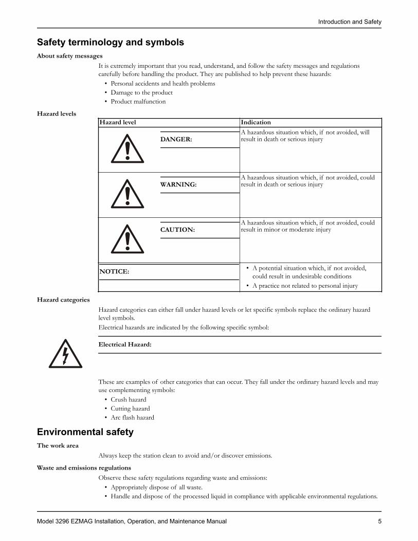
WARNING:Magnetic drive pumps contain very strong magnets that can pose health risks. Always observe theseguidelines:
• Avoid working with, being in proximity of, or handling the magnets contained in this pump if youhave any of these conditions:• An artificial cardiac pacemaker• An implanted defibrillator• A metallic prosthetic heart valve• Internal wound clips, from surgery• Prosthetic joints• Metallic wiring• Any other type of metallic, prosthetic device
• Individuals who have had any surgery, especially to the chest or head, and do not know if metallicclips were surgically implanted need to avoid work on this unit unless their physician can confirm thatno metallic devices exist.
Wash the skin and eyesDo the following if chemicals or hazardous fluids have come into contact with your eyes or your skin:
If you need to washyour...
Then...
Eyes 1. Hold your eyelids apart forcibly with your fingers.2. Rinse the eyes with eyewash or running water for at least 15 minutes.3. Seek medical attention.
Skin 1. Remove contaminated clothing.2. Wash the skin with soap and water for at least one minute.3. Seek medical attention, if required.
Safety regulations for Ex-approved products in potentially explosiveatmospheresGuidelines for compliance
Compliance is only fulfilled when the pump is operated within its intended use, for example within itsintended hydraulic range. The conditions of the service must not be changed without approval of anauthorized ITT representative. When installing or maintaining explosion-proof pumps, follow theseguidelines:
• Always install ATEX-approved equipment in compliance with the directive and applicable standards(IEC/EN 60079–14).
WARNING:This manual clearly identify accepted methods for disassembling units. These methods must be adhered to.Trapped liquid can rapidly expand and result in a violent explosion and injury. Never apply heat toimpellers, propellers, or their retaining devices to aid in their removal.
If there are any questions regarding these requirements, the intended use, or if the equipment requiresmodification, contact an ITT representative before you proceed.
Personnel requirementsITT disclaims all responsibility for work done by untrained and unauthorized personnel.
Introduction and Safety
Model 3296 EZMAG Installation, Operation, and Maintenance Manual 7

These are the personnel requirements for Ex-approved products in potentially explosive atmospheres:• All work on the product must be carried out by certified electricians and ITT-authorized mechanics.
Special rules apply to installations in explosive atmospheres.• All users must know about the risks of electric current and the chemical and physical characteristics of
the gas and/or vapor present in hazardous areas.• Any maintenance for Ex-approved products must conform to international and national standards
(for example IEC/EN 60079-17).
Product and product handling requirementsThese are the product and product handling requirements for Ex-approved products in potentiallyexplosive atmospheres:
• Only use the product in accordance with the approved motor data stated on the nameplates.• The Ex-approved product must never run dry during normal operation. Dry running during service
and inspection is only permitted outside the classified area.• Never start a pump without the proper priming.• Before you start working with the product, make sure that the product and the control panel are
isolated from the power supply and the control circuit, so they cannot be energized.• Do not open the product while it is energized or in an explosive gas atmosphere.• Make sure that thermal contacts are connected to a protection circuit according to the approval
classification of the product.• Intrinsically safe circuits are normally required for the automatic level-control system by the level
regulator if mounted in zone 0.• The yield stress of fasteners must be in accordance with the approval drawing and the product
specification.• Make sure that the equipment is properly maintained:
• Monitor the pump components and the end temperature of the liquid.• Maintain proper bearing lubrication.
• Do not modify the equipment without approval from an authorized ITT representative.• Only use parts that have been provided by an authorized ITT representative.
Equipment for monitoringFor additional safety, use condition-monitoring devices. Condition-monitoring devices include but are notlimited to these devices:
• Pressure gauges• Flow meters• Level indicators• Motor load readings• Temperature detectors• Bearing monitors• Leak detectors
Product warrantyCoverage
ITT undertakes to remedy faults in products from ITT under these conditions:• The faults are due to defects in design, materials, or workmanship.• The faults are reported to an ITT representative within the warranty period.• The product is used only under the conditions described in this manual.• The monitoring equipment incorporated in the product is correctly connected and in use.• All service and repair work is done by ITT-authorized personnel.• Genuine ITT parts are used.• Only Ex-approved spare parts and accessories authorized by ITT are used in Ex-approved products.
Introduction and Safety
8 Model 3296 EZMAG Installation, Operation, and Maintenance Manual

LimitationsThe warranty does not cover faults caused by these situations:
• Deficient maintenance• Improper installation• Modifications or changes to the product and installation made without consulting ITT• Incorrectly executed repair work• Normal wear and tear
ITT assumes no liability for these situations:• Bodily injuries• Material damages• Economic losses
Warranty claimITT products are high-quality products with expected reliable operation and long life. However, should theneed arise for a warranty claim, then contact your ITT representative.
Spare partsITT guarantees that spare parts will be available for 10 years after the manufacture of this product hasbeen discontinued.
Introduction and Safety
Model 3296 EZMAG Installation, Operation, and Maintenance Manual 9

Transportation and StorageInspect the deliveryInspect the package
1. Inspect the package for damaged or missing items upon delivery.2. Note any damaged or missing items on the receipt and freight bill.3. File a claim with the shipping company if anything is out of order.
If the product has been picked up at a distributor, make a claim directly to the distributor.
Inspect the unit1. Remove packing materials from the product.
Dispose of all packing materials in accordance with local regulations.2. Inspect the product to determine if any parts have been damaged or are missing.3. If applicable, unfasten the product by removing any screws, bolts, or straps.
For your personal safety, be careful when you handle nails and straps.4. Contact your sales representative if anything is out of order.
Transportation guidelines
Pump handling
WARNING:• Make sure that the pump cannot roll or fall over and injure people or damage property.• These pumps might use carbon or ceramic silicon carbide components. Do not drop the pump or
subject it to shock loads as this can damage the internal ceramic components.
NOTICE: Use a forklift truck or an overhead crane with sufficient capacity to move the pallet with thepump unit on top. Failure to do so can result in equipment damage.
Lifting methods
WARNING:• Assembled units and their components are heavy. Failure to properly lift and support this equipment
can result in serious physical injury and/or equipment damage. Lift equipment only at the specificallyidentified lifting points. Lifting devices such as eyebolts, slings, and spreaders must be rated, selected,and used for the entire load being lifted.
• Crush hazard. The unit and the components can be heavy. Use proper lifting methods and wear steel-toed shoes at all times.
• Do not attach sling ropes to shaft ends.
Table 1: MethodsPump type Lifting methodA bare pump without liftinghandles
Use a suitable sling attached properly to solid points like the casing, theflanges, or the frames.
A base-mounted pump Use slings under the pump casing and the drive unit, or under the baserails.
Transportation and Storage
10 Model 3296 EZMAG Installation, Operation, and Maintenance Manual
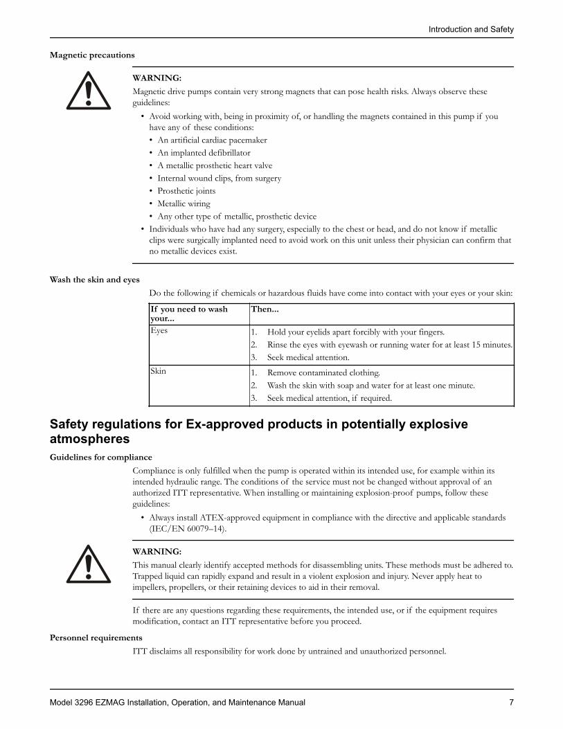
Examples
Figure 1: Proper lifting method for a bare pump
NOTICE:Do not use this lifting method to life a Polyshield ANSI Combo with the pump and motor mounted. Thiscan result in equipment damage.
Figure 2: Proper lifting method for a pump with a base and driver
NOTICE:Do not use this lifting method to life a Polyshield ANSI Combo with the pump and motor mounted. Thiscan result in equipment damage.
Transportation and Storage
Model 3296 EZMAG Installation, Operation, and Maintenance Manual 11
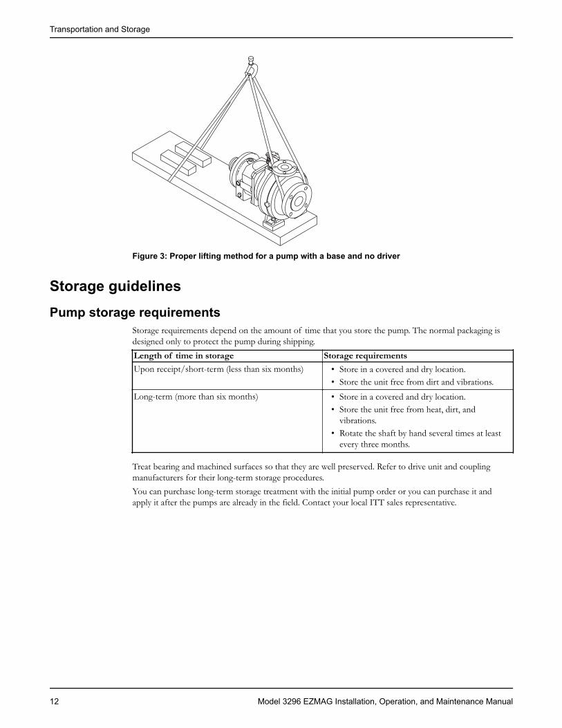
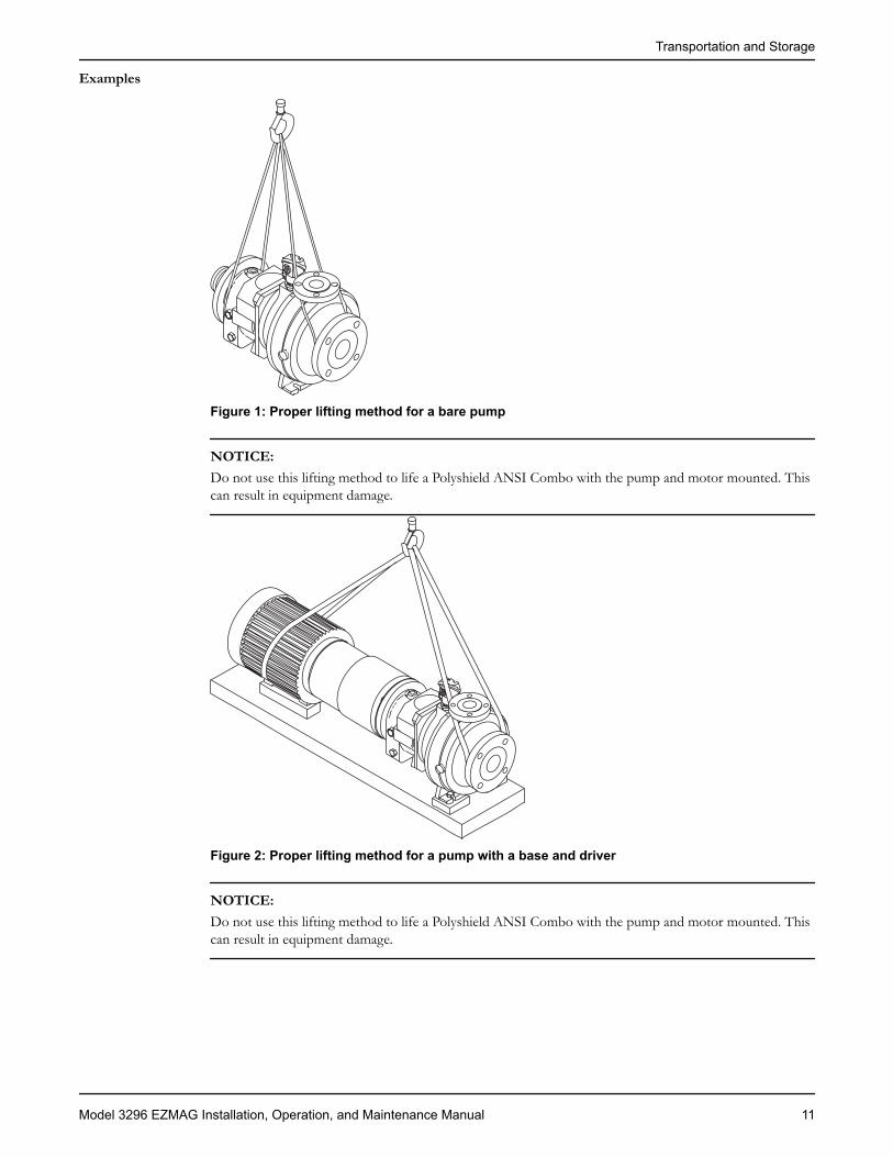
Figure 3: Proper lifting method for a pump with a base and no driver
Storage guidelines
Pump storage requirementsStorage requirements depend on the amount of time that you store the pump. The normal packaging isdesigned only to protect the pump during shipping.Length of time in storage Storage requirementsUpon receipt/short-term (less than six months) • Store in a covered and dry location.
• Store the unit free from dirt and vibrations.Long-term (more than six months) • Store in a covered and dry location.
• Store the unit free from heat, dirt, andvibrations.
• Rotate the shaft by hand several times at leastevery three months.
Treat bearing and machined surfaces so that they are well preserved. Refer to drive unit and couplingmanufacturers for their long-term storage procedures.You can purchase long-term storage treatment with the initial pump order or you can purchase it andapply it after the pumps are already in the field. Contact your local ITT sales representative.
Transportation and Storage
12 Model 3296 EZMAG Installation, Operation, and Maintenance Manual

Product DescriptionGeneral descriptionModel 3296 EZMAG
The Model 3296 EZMAG is a sealless centrifugal pump with an enclosed impeller that is driven by asynchronous magnetic coupling. Model 3296 EZMAG meets the dimensional standards of ANSI B73.1.
CasingThe casing is top centerline discharge and is self-venting. It incorporates a fully-confined gasket with ANSIClass 150 flanges that are serrated and raised-faced. The 3296 EZMAG is designed to have a metal-to-metal fit between the casing and the backplate.
Magnetic couplingThe magnetic coupling is a coaxial synchronous type that uses rare earth magnets. This concept results in acompact design and allows the impeller to turn at the same speed as the motor, which means that there isno slip between the drive and the driven magnets.
MagnetsTwo types of rare earth magnets are available:
• Neodymium Iron (NdFe) is used when pumped liquid temperatures are less than 365°F (180°C).• Samarium Cobalt (SmCo) is used when pumped liquid temperatures are between 365°F (180°C) and
536°F (280°C).
Containment shellThe containment shell isolates the pumped liquid from the atmosphere and is constructed from Hastelloy-C.
Sleeve bearings and thrust bearingsGoulds standard bearing material is Pure Sintered Alpha Grade Silicon Carbide. Dryguard™ bearings areavailable for dry-run protection.
ImpellerThe 3296 EZMAG uses an enclosed impeller that is hydraulically-balanced and keyed to the shaft.
Bearing frameThe standard configuration is cast iron with ball bearings that are flood oil–lubricated. Greased-for-lifebearings systems are available as an option. Bronze bearing isolators are provided for protection andreliability of the bearings and the lubricant.
Nameplate informationImportant information for ordering
Every pump has nameplates that provide information about the pump. The nameplates are located on thecasing and the bearing frame.When you order spare parts, identify this pump information:
• Model• Size• Serial number• Item numbers of the required parts
Refer to the nameplate on the pump casing for most of the information. See Parts List for item numbers.
Product Description
Model 3296 EZMAG Installation, Operation, and Maintenance Manual 13

Nameplate typesNameplate DescriptionATEX If applicable, your pump unit might have an ATEX nameplate affixed to the pump, the
baseplate, or the discharge head. The nameplate provides information about the ATEXspecifications of this pump.
Nameplate on the pump casing using English units
Table 2: Explanation of nameplate on the pump casingNameplate field ExplanationIMPLR. DIA. Impeller diameter, in inchesMAX. DIA. Maximum impeller diameter, in inchesGPM Rated pump flow, in gallons per minuteFT HD Rated pump head, in feetRPM Rated pump speed, revolutions per minuteMOD. Pump modelSIZE Size of the pumpSTD. NO. ANSI standard designationMAT L. CONST. Material of which the pump is constructedSER. NO. Serial number of the pumpMAX DSGN PSI@ 100F
Maximum pressure at 100ºF according to the pump design
Nameplate on the pump casing using metric units
Table 3: Explanation of the nameplate on the pump casingNameplate field ExplanationIMPLR. DIA. Impeller diameterMAX. DIA. Maximum impeller diameterM3/HR Rated pump flow, in cubic meters per hour
Product Description
14 Model 3296 EZMAG Installation, Operation, and Maintenance Manual
Nameplate field ExplanationM HD Rated pump head, in metersRPM Rated pump speed, in revolutions per minuteMOD. Pump modelSIZE Size of the pumpSTD. NO. ANSI standard designationMAT L. CONST Material of which the pump is constructedSER. NO. Serial number of the pumpMAX. DSGN KG/CM3 @20°C
Kilograms per cubic centimeter at 20°C
Nameplate on the bearing frame
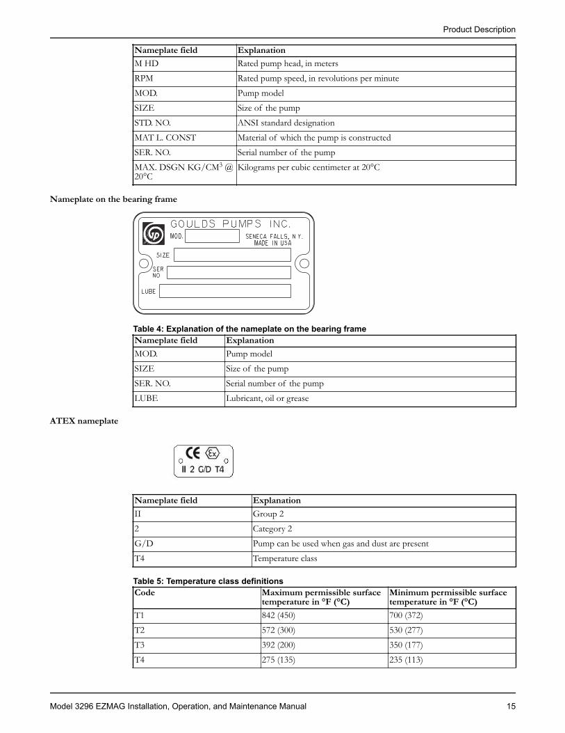
Table 4: Explanation of the nameplate on the bearing frameNameplate field ExplanationMOD. Pump modelSIZE Size of the pumpSER. NO. Serial number of the pumpLUBE Lubricant, oil or grease
ATEX nameplate
Nameplate field ExplanationII Group 22 Category 2G/D Pump can be used when gas and dust are presentT4 Temperature class
Table 5: Temperature class definitionsCode Maximum permissible surface
temperature in °F (°C)Minimum permissible surfacetemperature in °F (°C)
T1 842 (450) 700 (372)T2 572 (300) 530 (277)T3 392 (200) 350 (177)T4 275 (135) 235 (113)
Product Description
Model 3296 EZMAG Installation, Operation, and Maintenance Manual 15

Code Maximum permissible surfacetemperature in °F (°C)
Minimum permissible surfacetemperature in °F (°C)
T5 212 (100) Option not availableT6 185 (85) Option not available
NOTICE: Make sure that the code classifications on the pump are compatible with the specificenvironment in which you plan to install the equipment. If they are not compatible, do not operate theequipment and contact your ITT representative before you proceed.
Product Description
16 Model 3296 EZMAG Installation, Operation, and Maintenance Manual
InstallationPreinstallationPrecautions
WARNING:• When installing in a potentially explosive environment, make sure that the motor is properly certified.• You must earth (ground) all electrical equipment. This applies to the pump equipment, the driver, and
any monitoring equipment. Test the earth (ground) lead to verify that it is connected correctly.
NOTICE: Supervision by an authorized ITT representative is recommended to ensure proper installation.Failure to do so may result in equipment damage or decreased performance.
Evaluate the installation in order to determine that the Net Positive Suction Head Available (NPSHA)meets or exceeds the Net Positive Suction Head Required (NPSHR), as stated by the pump performancecurve.
Pump location guidelines
WARNING:Assembled units and their components are heavy. Failure to properly lift and support this equipment canresult in serious physical injury and/or equipment damage. Lift equipment only at the specifically identifiedlifting points. Lifting devices such as eyebolts, slings, and spreaders must be rated, selected, and used forthe entire load being lifted.
Guideline Explanation/commentKeep the pump as close to the liquid source aspractically possible.
This minimizes the friction loss and keeps the suctionpiping as short as possible.
Make sure that the space around the pump issufficient.
This facilitates ventilation, inspection, maintenance, andservice.
If you require lifting equipment such as a hoistor tackle, make sure that there is enough spaceabove the pump.
This makes it easier to properly use the liftingequipment and safely remove and relocate thecomponents to a safe location.
Protect the unit from weather and water damagedue to rain, flooding, and freezing temperatures.
This is applicable if nothing else is specified.
Do not install and operate the equipment inclosed systems unless the system is constructedwith properly-sized safety devices and controldevices.
Acceptable devices:• Pressure relief valves• Compression tanks• Pressure controls• Temperature controls• Flow controlsIf the system does not include these devices, consult theengineer or architect in charge before you operate thepump.
Take into consideration the occurrence ofunwanted noise and vibration.
The best pump location for noise and vibrationabsorption is on a concrete floor with subsoilunderneath.
Installation
Model 3296 EZMAG Installation, Operation, and Maintenance Manual 17

Foundation requirementsRequirements
• The foundation must be able to absorb any type of vibration and form a permanent, rigid support forthe pump unit.
• The location and size of the foundation bolt holes must match those shown on the assembly drawingprovided with the pump data package.
• Provide a flat, substantial concrete foundation in order to prevent strain and distortion when youtighten the foundation bolts.
• Sleeve-type and J-type foundation bolts are most commonly used. Both designs allow movement forthe final bolt adjustment.
Sleeve-type bolts
1
2
3
4
5
6
1. Baseplate2. Shims or wedges3. Foundation4. Sleeve5. Dam6. Bolt
J-type bolts
1
3
24
5
1. Baseplate2. Shims or wedges3. Foundation4. Dam5. Bolt
Baseplate-mounting proceduresPrepare the baseplate for mounting
1. Remove all the attached equipment from the baseplate.2. Clean the underside of the baseplate completely.3. If applicable, coat the underside of the baseplate with an epoxy primer.
Use an epoxy primer only if you used an epoxy-based grout.4. Remove the rust-proofing coat from the machined mounting pads using an appropriate solvent.5. Remove water and debris from the foundation-bolt holes.
Installation
18 Model 3296 EZMAG Installation, Operation, and Maintenance Manual

Install the baseplate using shims or wedgesRequired tools:
• Two sets of shims or wedges for each foundation bolt• Two machinist's levels• Baseplate-leveling worksheet
This procedure is applicable to cast iron and fabricated steel baseplates.1. Remove water and debris from the anchor bolt holes and sleeves.2. If you use sleeve-type bolts, fill the bolt sleeves with packing material or rags to prevent grout from
entering the bolt holes.3. Put the sets of wedges or shims on each side of each foundation bolt.
Make sure that the wedges extend 0.75 in. (19 mm) to 1.5 in. (38 mm) above the foundation toprovide adequate space for grouting. The wedges will provide adequate support for the baseplate afterit is grouted.
1
1. Shims or wedges
Figure 4: Top view
11. Shims or wedges
Figure 5: Side view4. Lower the baseplate carefully onto the foundation bolts.5. Put the machinist's levels across the mounting pads of the driver and the mounting pads of the pump.
NOTICE: Remove all dirt from the mounting pads in order to make sure that you achieve thecorrect leveling. Failure to do so can result in equipment damage or decreased performance.
6. Level the baseplate both lengthwise and across by adding or removing shims or moving the wedges.These are the leveling tolerances:
• A maximum difference of 0.125 in. (3.2 mm) lengthwise• A maximum difference of 0.059 in. (1.5 mm) across
You can use the baseplate-leveling worksheet when you take the readings.7. Hand-tighten the nuts for the foundation.
Installation
Model 3296 EZMAG Installation, Operation, and Maintenance Manual 19

Install the baseplate using jackscrewsTools required:
• Anti-seize compound• Jackscrews• Bar stock• Two machinist's levels• Baseplate-leveling worksheet
This procedure applies to the feature-fabricated steel baseplate and the advantage base baseplate.1. Apply an anti-seize compound on the jackscrews.
The compound makes it easier to remove the screws after you grout.2. Lower the baseplate carefully onto the foundation bolts and perform these steps:
a) Cut the plates from the bar stock and chamfer the edges of the plates in order to reduce stressconcentrations.
b) Put the plates between the jackscrews and the foundation surface.c) Use the four jackscrews in the corners in order to raise the baseplate above the foundation.
Make sure that the distance between the baseplate and the foundation surface is between 0.75 in.(19 mm) and 1.50 in. (38 mm).
d) Make sure that the center jackscrews do not touch the foundation surface yet.
1 2
34
1. Jackscrew2. Baseplate3. Foundation4. Plate
3. Level the driver mounting pads:
NOTICE: Remove all dirt from the mounting pads in order to make sure that you achieve thecorrect leveling. Failure to do so can result in equipment damage or decreased performance.
a) Put one machinist's level lengthwise on one of the two pads.b) Put the other machinist's level across the ends of the two pads.c) Level the pads by adjusting the four jackscrews in the corners.
Make sure that the machinist's level readings are as close to zero as possible, both lengthwise andacross.Use the baseplate-leveling worksheet when you take the readings.
Installation
20 Model 3296 EZMAG Installation, Operation, and Maintenance Manual

1 2
34 5 6
1. Machinist's levels2. Driver's mounting pads3. Foundation bolts4. Jackscrews5. Grout hole6. Pump's mounting pads
4. Turn the center jackscrews down so that they rest on their plates on the foundation surface.5. Level the pump mounting pads:
NOTICE: Remove all dirt from the mounting pads in order to make sure that you achieve thecorrect leveling. Failure to do so can result in equipment damage or decreased performance.
a) Put one machinist's level lengthwise on one of the two pads.b) Put the other level across the center of the two pads.c) Level the pads by adjusting the four jackscrews in the corners.
Make sure that the machinist's level readings are as close to zero as possible, both lengthwise andacross.
1 2
34 5 6
1. Driver's mounting pads2. Machinist's levels3. Foundation bolts4. Jackscrews5. Grout hole6. Pump's mounting pads
6. Hand-tighten the nuts for the foundation bolts.7. Check that the driver's mounting pads are level and adjust the jackscrews and the foundation bolts if
necessary.The correct level measurement is a maximum of 0.002 in./ft (0.0167 mm/m).
Installation
Model 3296 EZMAG Installation, Operation, and Maintenance Manual 21
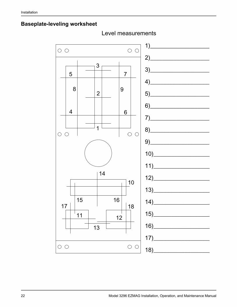
Baseplate-leveling worksheet
1
2
3
4
5
6
7
8 9
10
11 1213
14
15 1617 18
1)____________________
2)____________________
3)____________________
4)____________________
5)____________________
6)____________________
7)____________________
8)____________________
9)____________________
10)___________________
11)___________________
12)___________________
13)___________________
14)___________________
15)___________________
16)___________________
17)___________________
18)___________________
Level measurements
Installation
22 Model 3296 EZMAG Installation, Operation, and Maintenance Manual
Pump-to-driver alignmentPrecautions
WARNING:• Follow shaft alignment procedures in order to prevent catastrophic failure of drive components or
unintended contact of rotating parts. Follow the coupling installation and operation procedures fromthe coupling manufacturer.
• Always disconnect and lock out power to the driver before you perform any installation ormaintenance tasks. Failure to disconnect and lock out driver power will result in serious physicalinjury.
NOTICE: Proper alignment is the responsibility of the installer and the user of the unit. Check thealignment of frame-mounted units before you operate the unit. Failure to do so can result in equipmentdamage or decreased performance.
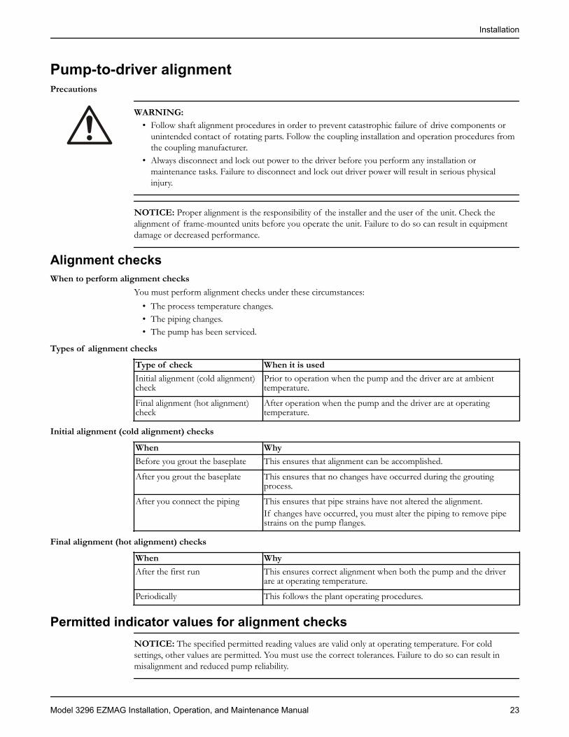
Alignment checksWhen to perform alignment checks
You must perform alignment checks under these circumstances:• The process temperature changes.• The piping changes.• The pump has been serviced.
Types of alignment checks
Type of check When it is usedInitial alignment (cold alignment)check
Prior to operation when the pump and the driver are at ambienttemperature.
Final alignment (hot alignment)check
After operation when the pump and the driver are at operatingtemperature.
Initial alignment (cold alignment) checks
When WhyBefore you grout the baseplate This ensures that alignment can be accomplished.
After you grout the baseplate This ensures that no changes have occurred during the groutingprocess.
After you connect the piping This ensures that pipe strains have not altered the alignment.If changes have occurred, you must alter the piping to remove pipestrains on the pump flanges.
Final alignment (hot alignment) checks
When WhyAfter the first run This ensures correct alignment when both the pump and the driver
are at operating temperature.
Periodically This follows the plant operating procedures.
Permitted indicator values for alignment checksNOTICE: The specified permitted reading values are valid only at operating temperature. For coldsettings, other values are permitted. You must use the correct tolerances. Failure to do so can result inmisalignment and reduced pump reliability.
Installation
Model 3296 EZMAG Installation, Operation, and Maintenance Manual 23
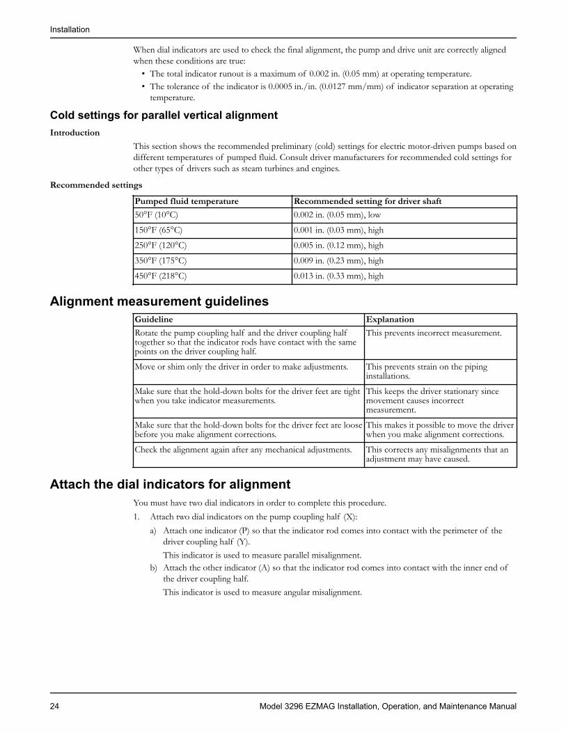
When dial indicators are used to check the final alignment, the pump and drive unit are correctly alignedwhen these conditions are true:
• The total indicator runout is a maximum of 0.002 in. (0.05 mm) at operating temperature.• The tolerance of the indicator is 0.0005 in./in. (0.0127 mm/mm) of indicator separation at operating
temperature.
Cold settings for parallel vertical alignmentIntroduction
This section shows the recommended preliminary (cold) settings for electric motor-driven pumps based ondifferent temperatures of pumped fluid. Consult driver manufacturers for recommended cold settings forother types of drivers such as steam turbines and engines.
Recommended settings
Pumped fluid temperature Recommended setting for driver shaft50°F (10°C) 0.002 in. (0.05 mm), low
150°F (65°C) 0.001 in. (0.03 mm), high
250°F (120°C) 0.005 in. (0.12 mm), high
350°F (175°C) 0.009 in. (0.23 mm), high
450°F (218°C) 0.013 in. (0.33 mm), high
Alignment measurement guidelinesGuideline ExplanationRotate the pump coupling half and the driver coupling halftogether so that the indicator rods have contact with the samepoints on the driver coupling half.
This prevents incorrect measurement.
Move or shim only the driver in order to make adjustments. This prevents strain on the pipinginstallations.
Make sure that the hold-down bolts for the driver feet are tightwhen you take indicator measurements.
This keeps the driver stationary sincemovement causes incorrectmeasurement.
Make sure that the hold-down bolts for the driver feet are loosebefore you make alignment corrections.
This makes it possible to move the driverwhen you make alignment corrections.
Check the alignment again after any mechanical adjustments. This corrects any misalignments that anadjustment may have caused.
Attach the dial indicators for alignmentYou must have two dial indicators in order to complete this procedure.1. Attach two dial indicators on the pump coupling half (X):
a) Attach one indicator (P) so that the indicator rod comes into contact with the perimeter of thedriver coupling half (Y).This indicator is used to measure parallel misalignment.
b) Attach the other indicator (A) so that the indicator rod comes into contact with the inner end ofthe driver coupling half.This indicator is used to measure angular misalignment.
Installation
24 Model 3296 EZMAG Installation, Operation, and Maintenance Manual

P
A
Y X
2. Rotate the pump coupling half (X) in order to check that the indicators are in contact with the drivercoupling half (Y) but do not bottom out.
3. Adjust the indicators if necessary.
Pump-to-driver alignment instructionsPerform angular alignment for a vertical correction
1. Set the angular alignment indicator to zero at the top-center position (12 o’clock) of the drivercoupling half (Y).
2. Rotate the indicator to the bottom-center position (6 o’clock).3. Record the indicator reading.
When thereadingvalue is...
Then...
Negative The coupling halves are farther apart at the bottom than at the top. Perform one ofthese steps:• Add shims in order to raise the feet of the driver at the shaft end.• Remove shims in order to lower the feet of the driver at the other end.
Positive The coupling halves are closer at the bottom than at the top. Perform one of thesesteps:• Remove shims in order to lower the feet of the driver at the shaft end.• Add shims in order to raise the feet of the driver at the other end.
X Y
Shims
Figure 6: Side view of an incorrect vertical alignment4. Repeat the previous steps until the permitted reading value is achieved.
Perform angular alignment for a horizontal correction1. Set the angular alignment indicator (A) to zero on left side of the driver coupling half (Y), 90° from
the top-center position (9 o’clock).2. Rotate the indicator through the top-center position to the right side, 180° from the start position
(3 o’clock).3. Record the indicator reading.
Installation
Model 3296 EZMAG Installation, Operation, and Maintenance Manual 25

When the reading value is... Then...Negative The coupling halves are farther apart on the right side than
the left. Perform one of these steps:• Slide the shaft end of the driver to the left.• Slide the opposite end to the right.
Positive The coupling halves are closer together on the right sidethan the left. Perform one of these steps:• Slide the shaft end of the driver to the right.• Slide the opposite end to the left.
Y X
Figure 7: Top view of an incorrect horizontal alignment4. Repeat the previous steps until the permitted reading value is achieved.
Perform parallel alignment for a vertical correctionBefore you start this procedure, make sure that the dial indicators are correctly set up.A unit is in parallel alignment when the parallel indicator (P) does not vary by more than 0.002 in.(0.05 mm) as measured at four points 90° apart at the operating temperature.When aligning a cold unit, see the Cold settings for vertical parallel alignment table.1. Set the parallel alignment indicator to zero at the top-center position (12 o’clock) of the driver
coupling half.2. Rotate the indicator to the bottom-center position (6 o’clock).3. Record the indicator reading.
When thereading valueis...
Then...
Negative The pump coupling half (X) is lower than the driver coupling half (Y). Removeshims of a thickness equal to half of the indicator reading value under each driverfoot.
Positive The pump coupling half (X) is higher than the driver coupling half. Add shims ofa thickness equal to half of the indicator reading value to each driver foot.
NOTICE:You must use an equal amount of shims with each driver foot to prevent misalignment. Failure to doso can result in equipment damage or decreased performance.
Y X
Shims
Figure 8: Side view of an incorrect vertical alignment4. Repeat the previous steps until the permitted reading value is achieved.
Installation
26 Model 3296 EZMAG Installation, Operation, and Maintenance Manual
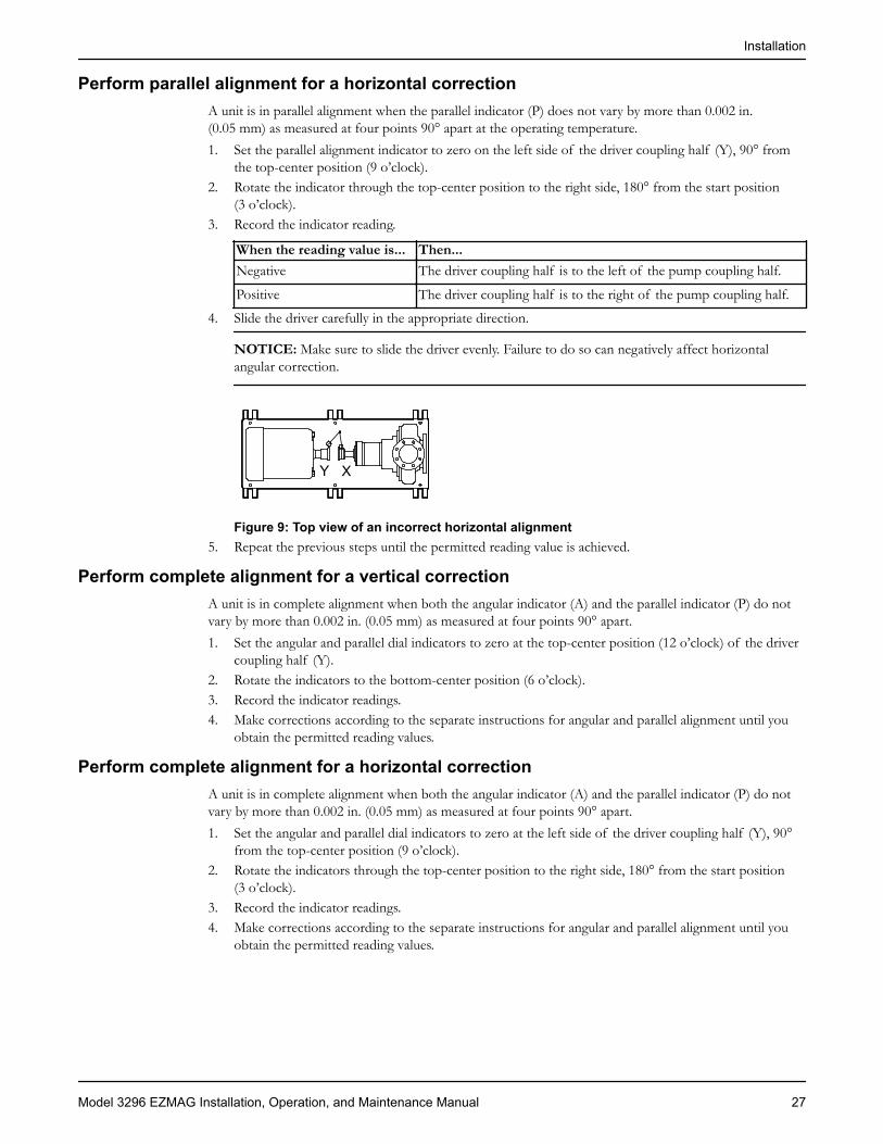
Perform parallel alignment for a horizontal correctionA unit is in parallel alignment when the parallel indicator (P) does not vary by more than 0.002 in.(0.05 mm) as measured at four points 90° apart at the operating temperature.1. Set the parallel alignment indicator to zero on the left side of the driver coupling half (Y), 90° from
the top-center position (9 o’clock).2. Rotate the indicator through the top-center position to the right side, 180° from the start position
(3 o’clock).3. Record the indicator reading.
When the reading value is... Then...Negative The driver coupling half is to the left of the pump coupling half.
Positive The driver coupling half is to the right of the pump coupling half.
4. Slide the driver carefully in the appropriate direction.
NOTICE: Make sure to slide the driver evenly. Failure to do so can negatively affect horizontalangular correction.
Y X
Figure 9: Top view of an incorrect horizontal alignment5. Repeat the previous steps until the permitted reading value is achieved.
Perform complete alignment for a vertical correctionA unit is in complete alignment when both the angular indicator (A) and the parallel indicator (P) do notvary by more than 0.002 in. (0.05 mm) as measured at four points 90° apart.1. Set the angular and parallel dial indicators to zero at the top-center position (12 o’clock) of the driver
coupling half (Y).2. Rotate the indicators to the bottom-center position (6 o’clock).3. Record the indicator readings.4. Make corrections according to the separate instructions for angular and parallel alignment until you
obtain the permitted reading values.
Perform complete alignment for a horizontal correctionA unit is in complete alignment when both the angular indicator (A) and the parallel indicator (P) do notvary by more than 0.002 in. (0.05 mm) as measured at four points 90° apart.1. Set the angular and parallel dial indicators to zero at the left side of the driver coupling half (Y), 90°
from the top-center position (9 o’clock).2. Rotate the indicators through the top-center position to the right side, 180° from the start position
(3 o’clock).3. Record the indicator readings.4. Make corrections according to the separate instructions for angular and parallel alignment until you
obtain the permitted reading values.
Installation
Model 3296 EZMAG Installation, Operation, and Maintenance Manual 27

Grout the baseplateRequired equipment:
• Cleaners: Do not use an oil-based cleaner because the grout will not bond to it. See the instructionsprovided by the grout manufacturer.
• Grout: Non-shrink grout is recommended.1. Clean all the areas of the baseplate that will come into contact with the grout.2. Build a dam around the foundation.3. Thoroughly wet the foundation that will come into contact with the grout.4. Pour grout through the grout hole into the baseplate up to the level of the dam.
When you pour the grout, remove air bubbles from it by using one of these methods:• Puddle with a vibrator.• Pump the grout into place.
5. Allow the grout to set.
1
76
2
3
4
51. Baseplate2. Shims or wedges3. Grout4. Foundation5. Sleeve6. Dam7. Bolt
6. Fill the remainder of the baseplate with grout, and allow the grout to set for at least 48 hours.
1
54 2
3
1. Baseplate2. Grout3. Foundation4. Dam5. Bolt
7. Tighten the foundation bolts.8. Recheck the alignment.
Installation
28 Model 3296 EZMAG Installation, Operation, and Maintenance Manual
Piping checklistsFastening
WARNING:• Only use fasteners of the proper size and material.• Replace all corroded fasteners.• Make sure that all fasteners are properly tightened and that there are no missing fasteners.
General piping checklistPrecautions
CAUTION:• Never draw piping into place by using force at the flanged connections of the pump. This can impose
dangerous strains on the unit and cause misalignment between the pump and driver. Pipe strainadversely affects the operation of the pump, which results in physical injury and damage to theequipment.
• Vary the capacity with the regulating valve in the discharge line. Never throttle the flow from thesuction side. This action can result in decreased performance, unexpected heat generation, andequipment damage.
NOTICE:Flange loads from the piping system, including those from the thermal expansion of the piping, must notexceed the limits of the pump. Deformation can result in contact with rotating parts, which can result inexcess heat generation, sparks, and premature failure.
Piping guidelinesGuidelines for piping are given in the Hydraulic Institute Standards available from the Hydraulic Instituteat 9 Sylvan Way, Parsippany, NJ 07054-3802. You must review this document before you install the pump.
Checklist
Check Explanation/comment CheckedCheck that all piping is supportedindependently of, and lined upnaturally with, the pump flange.
This helps to prevent:• Strain on the pump• Misalignment between the pump and the drive unit• Wear on the pump bearings, seal, and shafting
Keep the piping as short aspossible.
This helps to minimize friction losses.
Check that only necessary fittingsare used.
This helps to minimize friction losses.
Do not connect the piping to thepump until:• The grout for the baseplate or
sub-base becomes hard.• The hold-down bolts for the
pump and the driver aretightened.
—
Make sure that all the pipingjoints and fittings are airtight.
This prevents air from entering the piping system orleaks that occur during operation.
Installation
Model 3296 EZMAG Installation, Operation, and Maintenance Manual 29

Check Explanation/comment CheckedIf the pump handles corrosivefluids, make sure that the pipingallows you to flush out the liquidbefore you remove the pump.
—
If the pump handles liquids atelevated temperatures, make surethat the expansion loops andjoints are properly installed.
This helps to prevent misalignment due to linearexpansion of the piping.
Example: Installation for expansion
Correct Incorrect
1
1. Expansion loop/joint
Suction-piping checklistPerformance curve reference
Net positive suction head available (NPSHA) must always exceed NPSH required (NPSHR) as shown onthe published performance curve of the pump.Refer to the Hydraulic Institute for NPSH and pipe friction values needed in order to evaluate suctionpiping.
Suction-piping checks
Check Explanation/comment CheckedFlush all suction piping before you connect it to thepump.
This reduces the risk of pumpoperation problems.
Check that the suction piping fittings and joints areairtight and have no leaks.
—
Check that the distance between the inlet flange of thepump and the closest elbow is at least two pipediameters.
This minimizes the risk of cavitation inthe suction inlet of the pump due toturbulence.See the Example sections forillustrations.
Check that elbows in general do not have sharp bends. See the Example sections forillustrations.
Check that the suction piping is one or two sizeslarger than the suction inlet of the pump.
The suction piping must never have asmaller diameter than the suction inletof the pump.
Installation
30 Model 3296 EZMAG Installation, Operation, and Maintenance Manual
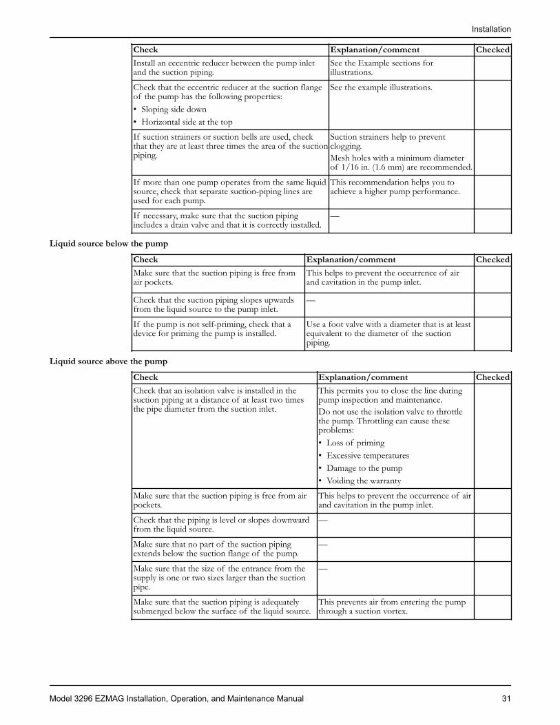
Check Explanation/comment CheckedInstall an eccentric reducer between the pump inletand the suction piping.
See the Example sections forillustrations.
Check that the eccentric reducer at the suction flangeof the pump has the following properties:• Sloping side down• Horizontal side at the top
See the example illustrations.
If suction strainers or suction bells are used, checkthat they are at least three times the area of the suctionpiping.
Suction strainers help to preventclogging.Mesh holes with a minimum diameterof 1/16 in. (1.6 mm) are recommended.
If more than one pump operates from the same liquidsource, check that separate suction-piping lines areused for each pump.
This recommendation helps you toachieve a higher pump performance.
If necessary, make sure that the suction pipingincludes a drain valve and that it is correctly installed.
—
Liquid source below the pump
Check Explanation/comment CheckedMake sure that the suction piping is free fromair pockets.
This helps to prevent the occurrence of airand cavitation in the pump inlet.
Check that the suction piping slopes upwardsfrom the liquid source to the pump inlet.
—
If the pump is not self-priming, check that adevice for priming the pump is installed.
Use a foot valve with a diameter that is at leastequivalent to the diameter of the suctionpiping.
Liquid source above the pump
Check Explanation/comment CheckedCheck that an isolation valve is installed in thesuction piping at a distance of at least two timesthe pipe diameter from the suction inlet.
This permits you to close the line duringpump inspection and maintenance.Do not use the isolation valve to throttlethe pump. Throttling can cause theseproblems:• Loss of priming• Excessive temperatures• Damage to the pump• Voiding the warranty
Make sure that the suction piping is free from airpockets.
This helps to prevent the occurrence of airand cavitation in the pump inlet.
Check that the piping is level or slopes downwardfrom the liquid source.
—
Make sure that no part of the suction pipingextends below the suction flange of the pump.
—
Make sure that the size of the entrance from thesupply is one or two sizes larger than the suctionpipe.
—
Make sure that the suction piping is adequatelysubmerged below the surface of the liquid source.
This prevents air from entering the pumpthrough a suction vortex.
Installation
Model 3296 EZMAG Installation, Operation, and Maintenance Manual 31

Correct IncorrectThe correct distance between the inlet flange of the pump andthe closest elbow is at least two pipe diameters.
1
2
1. Enough distance to prevent cavitation2. Eccentric reducer with a level top
Example: Suction piping equipment
Correct Incorrect
1
2
3
4
5
1. Suction pipe sloping upwards from liquid source2. Long-radius elbow3. Strainer4. Foot valve5. Eccentric reducer with a level top
1
1. Air pocket, because the eccentric reducer is notused and because the suction piping does not slopegradually upward from the liquid source
Discharge piping checklistChecklist
Check Explanation/comment CheckedCheck that an isolation valve isinstalled in the discharge line.
The isolation valve is required for:• Priming• Regulation of flow• Inspection and maintenance of the pumpSee Example: Discharge piping equipment forillustrations.
Check that a check valve is installed inthe discharge line, between theisolation valve and the pump dischargeoutlet.
The location between the isolation valve and thepump allows inspection of the check valve.The check valve prevents damage to the pump andseal due to the back flow through the pump, whenthe drive unit is shut off. It is also used to restrainthe liquid flow.
Installation
32 Model 3296 EZMAG Installation, Operation, and Maintenance Manual
Check Explanation/comment CheckedSee Example: Discharge piping equipment forillustrations.
If increasers are used, check that theyare installed between the pump and thecheck valve.
See Example: Discharge piping equipment forillustrations.
If quick-closing valves are installed inthe system, check that cushioningdevices are used.
This protects the pump from surges and waterhammer.
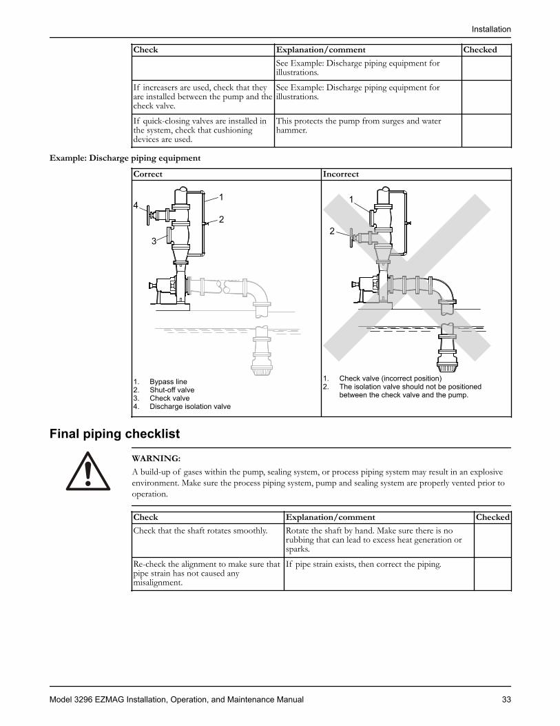
Example: Discharge piping equipment
Correct Incorrect
1
2
3
4
1. Bypass line2. Shut-off valve3. Check valve4. Discharge isolation valve
2
1
1. Check valve (incorrect position)2. The isolation valve should not be positioned
between the check valve and the pump.
Final piping checklist
WARNING:A build-up of gases within the pump, sealing system, or process piping system may result in an explosiveenvironment. Make sure the process piping system, pump and sealing system are properly vented prior tooperation.
Check Explanation/comment CheckedCheck that the shaft rotates smoothly. Rotate the shaft by hand. Make sure there is no
rubbing that can lead to excess heat generation orsparks.
Re-check the alignment to make sure thatpipe strain has not caused anymisalignment.
If pipe strain exists, then correct the piping.
Installation
Model 3296 EZMAG Installation, Operation, and Maintenance Manual 33
Commissioning, Startup, Operation, andShutdownPreparation for startup
WARNING:• Failure to follow these precautions before you start the pump will lead to serious personal injury and
equipment failure.• Never operate the pump without the coupling guard correctly installed.• Always disconnect and lock out power to the driver before you perform any installation or
maintenance tasks. Failure to disconnect and lock out driver power will result in serious physicalinjury.
• Operating the pump in reverse rotation can result in the contact of metal parts, heat generation, andbreach of containment.
Precautions
NOTICE:• Verify the driver settings before you start the pump.• Make sure that the warm-up rate does not exceed 2.5°F (1.4°C) per minute.
You must follow these precautions before you start the pump:• Flush and clean the system thoroughly to remove dirt or debris in the pipe system in order to prevent
premature failure at initial startup.• Bring variable-speed drivers to the rated speed as quickly as possible.• If temperatures of the pumped fluid will exceed 200°F (93°C), then warm up the pump prior to
operation. Circulate a small amount of fluid through the pump until the casing temperature is within100°F (38°C) of the fluid temperature.
At initial startup, do not adjust the variable-speed drivers or check for speed governor or over-speed tripsettings while the variable-speed driver is coupled to the pump. If the settings have not been verified, thenuncouple the unit and refer to instructions supplied by the driver manufacturer.
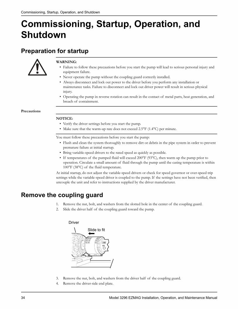
Remove the coupling guard1. Remove the nut, bolt, and washers from the slotted hole in the center of the coupling guard.2. Slide the driver half of the coupling guard toward the pump.
Driver
Slide to fit
3. Remove the nut, bolt, and washers from the driver half of the coupling guard.4. Remove the driver-side end plate.
Commissioning, Startup, Operation, and Shutdown
34 Model 3296 EZMAG Installation, Operation, and Maintenance Manual

234B
Driver
5. Remove the driver half of the coupling guard:a) Slightly spread the bottom apart.b) Lift upwards.
1 2
3
1. Annular groove2. Driver half of the coupling guard3. Driver
6. Remove the remaining nut, bolt, and washers from the pump half of the coupling guard.It is not necessary to remove the end plate from the pump side of the bearing housing. You can accessthe bearing-housing tap bolts without removing this end plate if maintenance of internal pump partsis necessary.
7. Remove the pump half of the coupling guard:a) Slightly spread the bottom apart.b) Lift upwards.
Commissioning, Startup, Operation, and Shutdown
Model 3296 EZMAG Installation, Operation, and Maintenance Manual 35

1
2
3
4
1. Annular groove2. Pump-side end plate3. Driver4. Pump half of the coupling guard
Check the rotationWARNING:
• Operating the pump in reverse rotation can result in the contact of metal parts, heat generation, andbreach of containment.
• Always disconnect and lock out power to the driver before you perform any installation ormaintenance tasks. Failure to disconnect and lock out driver power will result in serious physicalinjury.
1. Lock out power to the driver.2. Make sure that the coupling hubs are fastened securely to the shafts.3. Make sure that the coupling spacer is removed.
The pump ships with the coupling spacer removed.4. Unlock power to the driver.5. Make sure that everyone is clear, and then jog the driver long enough to determine that the direction
of rotation corresponds to the arrow on the bearing housing, or close-coupled frame.6. Lock out power to the driver.
Couple the pump and driverWARNING:Always disconnect and lock out power to the driver before you perform any installation or maintenancetasks. Failure to disconnect and lock out driver power will result in serious physical injury.
Couplings must have proper certification to be used in an ATEX classified environment. Use theinstructions from the coupling manufacturer in order to lubricate and install the coupling.
Commissioning, Startup, Operation, and Shutdown
36 Model 3296 EZMAG Installation, Operation, and Maintenance Manual
Install the coupling guard
WARNING:• Never operate a pump without a properly installed coupling guard. Personal injury will occur if you
run the pump without a coupling guard.• Always disconnect and lock out power to the driver before you perform any installation or
maintenance tasks. Failure to disconnect and lock out driver power will result in serious physicalinjury.
• The coupling used in an Ex-classified environment must be properly certified and must beconstructed from a non-sparking material.
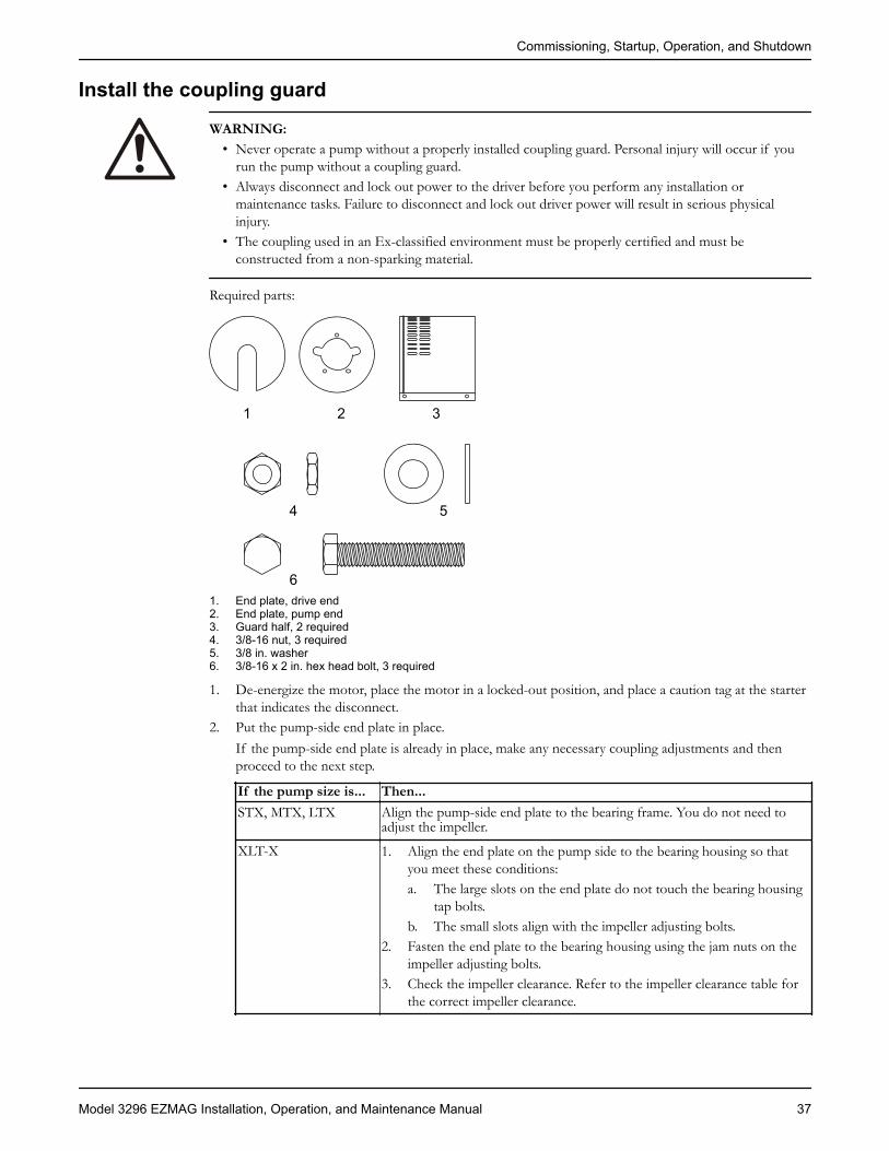
Required parts:
1 2 3
4 5
61. End plate, drive end2. End plate, pump end3. Guard half, 2 required4. 3/8-16 nut, 3 required5. 3/8 in. washer6. 3/8-16 x 2 in. hex head bolt, 3 required
1. De-energize the motor, place the motor in a locked-out position, and place a caution tag at the starterthat indicates the disconnect.
2. Put the pump-side end plate in place.If the pump-side end plate is already in place, make any necessary coupling adjustments and thenproceed to the next step.
If the pump size is... Then...STX, MTX, LTX Align the pump-side end plate to the bearing frame. You do not need to
adjust the impeller.
XLT-X 1. Align the end plate on the pump side to the bearing housing so thatyou meet these conditions:a. The large slots on the end plate do not touch the bearing housing
tap bolts.b. The small slots align with the impeller adjusting bolts.
2. Fasten the end plate to the bearing housing using the jam nuts on theimpeller adjusting bolts.
3. Check the impeller clearance. Refer to the impeller clearance table forthe correct impeller clearance.
Commissioning, Startup, Operation, and Shutdown
Model 3296 EZMAG Installation, Operation, and Maintenance Manual 37

STX, MTX, LTX
12
3
4
XLT-X
1. Driver2. Pump end plate3. Bearing housing4. Jam nut
3. Put the pump-half of the coupling guard in place:a) Slightly spread the bottom apart.b) Place the coupling guard half over the pump-side end plate.
Commissioning, Startup, Operation, and Shutdown
38 Model 3296 EZMAG Installation, Operation, and Maintenance Manual

1
2
3
4
1. Annular groove2. Pump-side end plate3. Driver4. Pump half of the coupling guardThe annular groove in the coupling guard half must fit around the end plate.
1
2
3
1. Annular groove2. End plate (pump end)3. Guard half
4. Use a bolt, a nut, and two washers to secure the coupling guard half to the end plate. Tighten securely.
1 2 3
1. Nut2. Washer3. Bolt
5. Put the driver half of the coupling guard in place:a) Slightly spread the bottom apart.
Commissioning, Startup, Operation, and Shutdown
Model 3296 EZMAG Installation, Operation, and Maintenance Manual 39
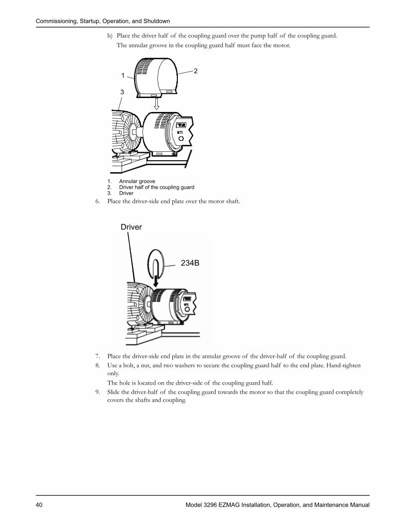
b) Place the driver half of the coupling guard over the pump half of the coupling guard.The annular groove in the coupling guard half must face the motor.
1 2
3
1. Annular groove2. Driver half of the coupling guard3. Driver
6. Place the driver-side end plate over the motor shaft.
234B
Driver
7. Place the driver-side end plate in the annular groove of the driver-half of the coupling guard.8. Use a bolt, a nut, and two washers to secure the coupling guard half to the end plate. Hand-tighten
only.The hole is located on the driver-side of the coupling guard half.
9. Slide the driver-half of the coupling guard towards the motor so that the coupling guard completelycovers the shafts and coupling.
Commissioning, Startup, Operation, and Shutdown
40 Model 3296 EZMAG Installation, Operation, and Maintenance Manual

Driver
Slide to fit
10. Use a nut, a bolt, and two washers to secure the coupling guard halves together.11. Tighten all nuts on the guard assembly.
WARNING:Never operate the pump without the coupling guard correctly installed.
Bearing lubricationWARNING:Pumps are shipped without oil. Oil-lubricated anti-friction bearings must be lubricated at the job site.
These bearing lubrication sections list different pumped-fluid temperatures. If your pump is ATEXcertified and your pumped-fluid temperature exceeds the permitted temperature values, then consult yourITT representative.
Lubrication requirementsPump type RequirementsClose coupled Close-coupled pumps do not have bearings that
require lubrication.Frame mounted • The oil level is measured through the sight glass.
• The oil level must not fall below the center ofthe sight glass.
• An increase in oil level may be noted afterstartup due to oil circulation within the bearingframe.
Lubricating-oil requirementsOil quality requirements
Use a high-quality turbine oil with rust and oxidation inhibitors rated at 68 cSt. at 100°F (38°C).
Oil requirements based on temperatureFor the majority of operating conditions, bearing temperatures run between 120°F (49°C) and 180°F(82°C), and you can use an oil of ISO viscosity grade 68 at 100°F (38°C). If temperatures exceed 180°F(82°C), refer to the table for temperature requirements.
Commissioning, Startup, Operation, and Shutdown
Model 3296 EZMAG Installation, Operation, and Maintenance Manual 41

Temperature Oil requirementBearing temperatures exceed 180°F (82°C) Use ISO viscosity grade 100. Bearing temperatures
are generally about 20°F (11°C) higher than bearing-housing outer surface temperatures.
Pumped-fluid temperatures exceed 350°F (177°C) Use synthetic lubrication.
Acceptable oil for lubricating bearingsAcceptable lubricants
Brand Lubricant typeChevron GTS Oil 68Exxon Teresstic EP 68Mobil DTE 26 300 SSU @ 100°F (38°C)Philips Mangus Oil 315Shell Tellus Oil 68Royal Purple SYNFILM ISO VG 68 Synthetic LubeGulf Harmony 68
Lubricate the bearings with oilUse a high-quality turbine oil with rust and oxidation inhibitors.1. Remove the fill plug.2. Fill the bearing frame with oil through the filler connection, which is located on top of the bearing
frame.Fill the bearing frame with oil until the oil level reaches the middle of the sight glass (319).
113A
319
Oil lubricatedbearings
Correctlevel
3. Replace the fill plug.
Greased-for-life bearing lubricationThe bearing manufacturer fills greased-for-life bearings with grease and seals them at the factory. You donot need to lubricate or seal these bearings. Refer to the Maintenance chapter for re-greasing andmaintenance procedures for these bearings.
Pump primingPrime the pump with the suction supply above the pump
1. Slowly open the suction isolation valve.2. Open the air vents on the suction and discharge piping until the pumped fluid flows out.3. Close the air vents.
Commissioning, Startup, Operation, and Shutdown
42 Model 3296 EZMAG Installation, Operation, and Maintenance Manual

12
3
1. Discharge isolation valve2. Check valve3. Suction isolation valve
Prime the pump with the suction supply below the pumpUse a foot valve and an outside source of liquid in order to prime the pump. The liquid can come fromone of these sources:
• A priming pump• A pressurized discharge line• Another outside supply
1. Close the discharge isolation valve.2. Open the air vent valves in the casing.3. Open the valve in the outside supply line until only liquid escapes from the vent valves.4. Close the vent valves.5. Close the outside supply line.This illustration is an example of priming the pump with a foot valve and an outside supply:
12
3
4
5
1. Discharge isolation valve2. Shutoff valve3. From outside supply4. Foot valve5. Check valve
This illustration is an example of priming the pump with a foot valve using a bypass around the checkvalve:
Commissioning, Startup, Operation, and Shutdown
Model 3296 EZMAG Installation, Operation, and Maintenance Manual 43

1
2
3
4
5
1. By-pass line2. Shutoff valve3. Foot valve4. Check valve5. Discharge isolation valve
Other methods of priming the pumpYou can also use these methods in order to prime the pump:
• Prime by ejector• Prime by automatic priming pump
Start the pumpWARNING:Continuous operation against a closed discharge valve can vaporize liquid. This condition can cause anexplosion due to confined vapor that is under high pressure and temperature.
CAUTION:• Immediately observe the pressure gauges. If discharge pressure is not quickly attained, stop the driver,
reprime, and attempt to restart the pump.• Observe the pump for vibration levels, bearing temperature, and excessive noise. If normal levels are
exceeded, shut down the pump and resolve the issue.• Continuous operation against a closed discharge valve will cause the pump to overheat. Overheating
the magnetic drive assembly will weaken or ruin the magnets.
Before you start the pump, you must perform these tasks:• Open the suction valve.• Open any recirculation or cooling lines.
1. Fully close or partially open the discharge valve, depending on system conditions.2. Start the driver.3. Slowly open the discharge valve until the pump reaches the desired flow.4. Immediately check the pressure gauge to ensure that the pump quickly reaches the correct discharge
pressure.
Commissioning, Startup, Operation, and Shutdown
44 Model 3296 EZMAG Installation, Operation, and Maintenance Manual
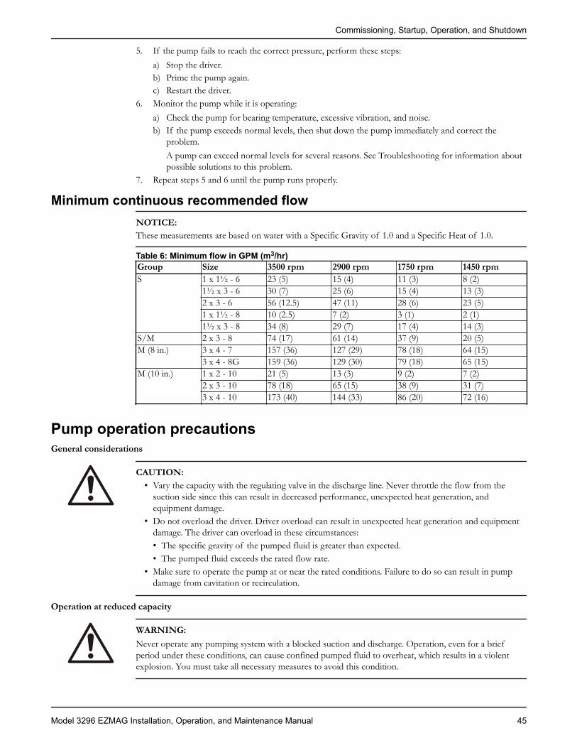
5. If the pump fails to reach the correct pressure, perform these steps:a) Stop the driver.b) Prime the pump again.c) Restart the driver.
6. Monitor the pump while it is operating:a) Check the pump for bearing temperature, excessive vibration, and noise.b) If the pump exceeds normal levels, then shut down the pump immediately and correct the
problem.A pump can exceed normal levels for several reasons. See Troubleshooting for information aboutpossible solutions to this problem.
7. Repeat steps 5 and 6 until the pump runs properly.
Minimum continuous recommended flowNOTICE:These measurements are based on water with a Specific Gravity of 1.0 and a Specific Heat of 1.0.
Table 6: Minimum flow in GPM (m3/hr)Group Size 3500 rpm 2900 rpm 1750 rpm 1450 rpmS 1 x 1½ - 6 23 (5) 15 (4) 11 (3) 8 (2)
1½ x 3 - 6 30 (7) 25 (6) 15 (4) 13 (3)2 x 3 - 6 56 (12.5) 47 (11) 28 (6) 23 (5)1 x 1½ - 8 10 (2.5) 7 (2) 3 (1) 2 (1)1½ x 3 - 8 34 (8) 29 (7) 17 (4) 14 (3)
S/M 2 x 3 - 8 74 (17) 61 (14) 37 (9) 20 (5)M (8 in.) 3 x 4 - 7 157 (36) 127 (29) 78 (18) 64 (15)
3 x 4 - 8G 159 (36) 129 (30) 79 (18) 65 (15)M (10 in.) 1 x 2 - 10 21 (5) 13 (3) 9 (2) 7 (2)
2 x 3 - 10 78 (18) 65 (15) 38 (9) 31 (7)3 x 4 - 10 173 (40) 144 (33) 86 (20) 72 (16)
Pump operation precautionsGeneral considerations
CAUTION:• Vary the capacity with the regulating valve in the discharge line. Never throttle the flow from the
suction side since this can result in decreased performance, unexpected heat generation, andequipment damage.
• Do not overload the driver. Driver overload can result in unexpected heat generation and equipmentdamage. The driver can overload in these circumstances:• The specific gravity of the pumped fluid is greater than expected.• The pumped fluid exceeds the rated flow rate.
• Make sure to operate the pump at or near the rated conditions. Failure to do so can result in pumpdamage from cavitation or recirculation.
Operation at reduced capacity
WARNING:Never operate any pumping system with a blocked suction and discharge. Operation, even for a briefperiod under these conditions, can cause confined pumped fluid to overheat, which results in a violentexplosion. You must take all necessary measures to avoid this condition.
Commissioning, Startup, Operation, and Shutdown
Model 3296 EZMAG Installation, Operation, and Maintenance Manual 45

CAUTION:• Avoid excessive vibration levels. Excessive vibration levels can damage the bearings, stuffing box or
seal chamber, and the mechanical seal, which can result in decreased performance.• Avoid increased radial load. Failure to do so can cause stress on the shaft and bearings.• Avoid heat build-up. Failure to do so can cause rotating parts to score or seize.• Avoid cavitation. Failure to do so can cause damage to the internal surfaces of the pump.
Operation under freezing conditions
NOTICE:Do not expose an idle pump to freezing conditions. Drain all liquid that is inside the pump and the coolingcoils. Failure to do so can cause liquid to freeze and damage the pump.
Temperature ratings
CAUTION:Do not operate the pump above the rated temperature range of the magnets. This will weaken or ruin themagnets. The rated temperature is 250°F (121°C) for all sizes.
Magnetic types Drive destination Rated temperatureNeodymium iron (NdFe) A, B, C, D, E, F, G, H, I, J, K 356°F (180°C)Samarium Cobalt (SmCo) AA, BB, CC, DD, EE, FF, GG,
HH, II, JJ, KK536°F (280°C)
Shut down the pumpWARNING:The pump can handle hazardous and toxic fluids. Identify the contents of the pump and observe properdecontamination procedures in order to eliminate the possible exposure to any hazardous or toxic fluids.Wear the proper personal protective equipment. Potential hazards include, but are not limited to, hightemperature, flammable, acidic, caustic, explosive, and other risks. You must handle and dispose ofpumped fluid in compliance with the applicable environmental regulations.
1. Slowly close the discharge valve.2. Shut down and lock the driver to prevent accidental rotation.
Make the final alignment of the pump and driverWARNING:
• Always disconnect and lock out power to the driver before you perform any installation ormaintenance tasks. Failure to disconnect and lock out driver power will result in serious physicalinjury.
• Follow shaft alignment procedures in order to prevent catastrophic failure of drive components orunintended contact of rotating parts. Follow the coupling installation and operation procedures fromthe coupling manufacturer.
You must check the final alignment after the pump and driver are at operating temperature. For initialalignment instructions, see the Installation chapter.1. Run the unit under actual operating conditions for enough time to bring the pump, driver, and
associated system to operating temperature.2. Shut down the pump and the driver.3. Remove the coupling guard.
Commissioning, Startup, Operation, and Shutdown
46 Model 3296 EZMAG Installation, Operation, and Maintenance Manual

See Remove the coupling guard in the Maintenance chapter.4. Check the alignment while the unit is still hot.
See Pump-to-driver alignment in the Installation chapter.5. Reinstall the coupling guard.6. Restart the pump and driver.
Commissioning, Startup, Operation, and Shutdown
Model 3296 EZMAG Installation, Operation, and Maintenance Manual 47
MaintenanceMaintenance scheduleMaintenance inspections
A maintenance schedule includes these types of inspections:• Routine maintenance• Routine inspections• Three-month inspections• Annual inspections
Shorten the inspection intervals appropriately if the pumped fluid is abrasive or corrosive or if theenvironment is classified as potentially explosive.
Routine maintenancePerform these tasks whenever you perform routine maintenance:
• Lubricate the bearings.• Inspect the seal.• Perform a vibration analysis.• Monitor the discharge pressure.• Monitor the temperature.
Routine inspectionsPerform these tasks whenever you check the pump during routine inspections:
• Check the level and condition of the oil through the sight glass on the bearing frame.• Check for unusual noise, vibration, and bearing temperatures.• Check the pump and piping for leaks.• Analyze the vibration.
Three-month inspectionsPerform these tasks every three months:
• Check that the foundation and the hold-down bolts are tight.• Change the oil every three months (2000 operating hours) at minimum.
• Change the oil more often if there are adverse atmospheric or other conditions that mightcontaminate or break down the oil.
• Check the shaft alignment, and realign as required.
Annual inspectionsPerform these inspections one time each year:
• Check the pump capacity.• Check the pump pressure.• Check the pump power.
If the pump performance does not satisfy your process requirements, and the process requirements havenot changed, then perform these steps:1. Disassemble the pump.2. Inspect it.3. Replace worn parts.
Maintenance
48 Model 3296 EZMAG Installation, Operation, and Maintenance Manual

Bearing maintenanceLubrication schedule
Type of bearing First lubrication Lubrication intervalsOil lubricated Change the oil after 200 hours for
new bearings.After the first 200 hours, changethe oil every 4000 operating hoursor every six months.
DisassemblyDisassembly precautions
WARNING:• Chemical hazard. You must individually decontaminate each component according to all federal, state,
local, and company environmental regulations.• A build up of gases within the pump, sealing system, or process-piping system can result in an
explosive environment within the pump. Make sure that the process piping system, pump, and sealingsystem are properly vented prior to operation.
• Process fluid leaks can result in an explosive atmosphere. Follow all pump and seal assemblyprocedures.
• Make sure that the pump is isolated from the system and that pressure is relieved before youdisassemble the pump, remove plugs, open vent or drain valves, or disconnect the piping.
• Crush hazard. The unit and the components can be heavy. Use proper lifting methods and wear steel-toed shoes at all times.
• The pump can handle hazardous and toxic fluids. Identify the contents of the pump and observeproper decontamination procedures in order to eliminate the possible exposure to any hazardous ortoxic fluids. Wear the proper personal protective equipment. Potential hazards include, but are notlimited to, high temperature, flammable, acidic, caustic, explosive, and other risks. You must handleand dispose of pumped fluid in compliance with the applicable environmental regulations.
CAUTION:• You must keep the shop area clean and free of any substances that can contaminate the magnets, such
as ferrous metals.• The magnets in this unit are extremely powerful. Beware of serious injury to fingers and hands. Keep
magnetic drive components and magnetic tools apart by a minimum of 3 ft (1 m).
NOTICE:Use a bench with a non-magnetic work surface such as wood or brass when you work on the pump.
Required tools
WARNING:This pump contains extremely strong magnets. You must use non-magnetic tools and work surfaces.
Tools• Assorted metric open-end or socket sizes 13 mm, 17 mm, 18 mm, 19 mm, and 24 mm• Hex wrenches, sizes 2.5 mm, 3 mm, 5 mm, and 6 mm with a 4.75 in. (12.07 cm) minimum reach• Hex wrench, size 8 mm with 6 in. (15 cm) minimum reach• Torque wrench
Maintenance
Model 3296 EZMAG Installation, Operation, and Maintenance Manual 49

• Strap wrench• 3/8 in. eyebolt
Prepare the pump for disassembly1. Lock out power to the driver.
WARNING:Always disconnect and lock out power to the driver before you perform any installation or maintenancetasks. Failure to disconnect and lock out driver power will result in serious physical injury.
2. Shut off all valves that control flow to and from the pump.3. Drain and flush the pump before you remove it from the piping.4. Isolate the pump from the system and then flush the pump using a compatible liquid.5. Disconnect all piping and auxiliary equipment.6. For the frame-mounted pump, remove the coupling guard and coupling.7. Remove the casing foot and frame and C-face motor-support foot bolts.8. Remove the pump from the baseplate.9. For the frame-mounted pump, drain the oil.10. Decontaminate the pump:
a) Connect a clean-flush liquid supply to the discharge nozzle.b) Collect the flushed liquid as it drains out of the drain connection.c) Flush the pump in order to remove residue.
Remove the frame assembly and shaft (frame-mounted pump)1. Secure the pump on a workbench or worktop with the suction nozzle facing down.2. Screw the 3/8 in. eyebolt into the drive shaft.3. Remove the screws (370B) holding the bearing frame to the frame adapter.
1
2
3
4
5
1. Frame-to-adapter hex screw (370B)2. Frame assembly3. Mag drive carrier4. Frame-to-adapter gasket (360W)5. Adapter
Maintenance
50 Model 3296 EZMAG Installation, Operation, and Maintenance Manual
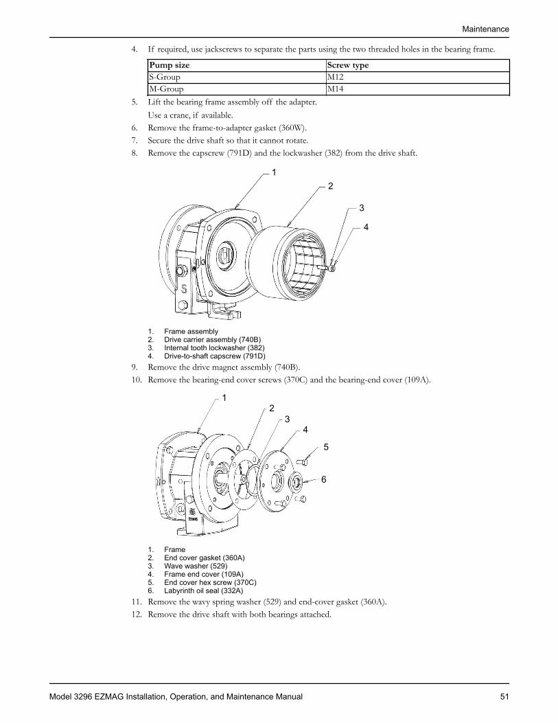
4. If required, use jackscrews to separate the parts using the two threaded holes in the bearing frame.
Pump size Screw typeS-Group M12M-Group M14
5. Lift the bearing frame assembly off the adapter.Use a crane, if available.
6. Remove the frame-to-adapter gasket (360W).7. Secure the drive shaft so that it cannot rotate.8. Remove the capscrew (791D) and the lockwasher (382) from the drive shaft.
12
3
4
1. Frame assembly2. Drive carrier assembly (740B)3. Internal tooth lockwasher (382)4. Drive-to-shaft capscrew (791D)
9. Remove the drive magnet assembly (740B).10. Remove the bearing-end cover screws (370C) and the bearing-end cover (109A).
12
34
5
6
1. Frame2. End cover gasket (360A)3. Wave washer (529)4. Frame end cover (109A)5. End cover hex screw (370C)6. Labyrinth oil seal (332A)
11. Remove the wavy spring washer (529) and end-cover gasket (360A).12. Remove the drive shaft with both bearings attached.
Maintenance
Model 3296 EZMAG Installation, Operation, and Maintenance Manual 51

1
23
1. Labyrinth oil seal (333D)2. Bearing frame (228)3. Drive with shaft bearings
13. Remove the labyrinth oil seals (332A and 333D).14. Remove both radial ball bearings using a press.
The radial ball bearings lie against the shaft collar.
Remove the frame assembly and shaft (close-coupled pump)1. Secure the complete pump on a workbench in either a horizontal or a vertical position.2. Remove the hex screws (370B) that hold the motor adapter (503) to the frame adapter (108).
12
3
1. Frame-to-adapter hex screw (370B)2. Close-coupled adapter (503)3. Frame-to-adapter gasket (360W)
3. If necessary, remove the motor adapter (503) from the frame adapter (108) using two levers or pry-bars.There are also two threaded holes (size M12) in the close-coupled motor adapter (503) for jackscrews.
4. Lift the motor and motor adapter assembly off the frame adapter.Use a crane, if necessary.
5. Remove the gasket (360W).
Maintenance
52 Model 3296 EZMAG Installation, Operation, and Maintenance Manual
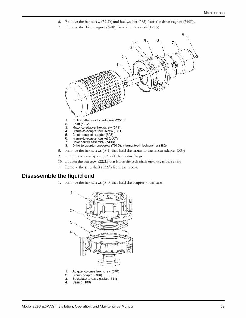
6. Remove the hex screw (791D) and lockwasher (382) from the drive magnet (740B).7. Remove the drive magnet (740B) from the stub shaft (122A).
1
2
34 5 6 7
8
1. Stub shaft–to-motor setscrew (222L)2. Shaft (122A)3. Motor-to-adapter hex screw (371)4. Frame-to-adapter hex screw (370B)5. Close-coupled adapter (503)6. Frame-to-adapter gasket (360W)7. Drive carrier assembly (740B)8. Drive-to-adapter capscrew (791D), internal tooth lockwasher (382)
8. Remove the hex screws (371) that hold the motor to the motor adapter (503).9. Pull the motor adapter (503) off the motor flange.10. Loosen the setscrew (222L) that holds the stub shaft onto the motor shaft.11. Remove the stub shaft (122A) from the motor.
Disassemble the liquid end1. Remove the hex screws (370) that hold the adapter to the case.
1
2
3
4
1. Adapter-to-case hex screw (370)2. Frame adapter (108)3. Backplate-to-case gasket (351)4. Casing (100)
Maintenance
Model 3296 EZMAG Installation, Operation, and Maintenance Manual 53
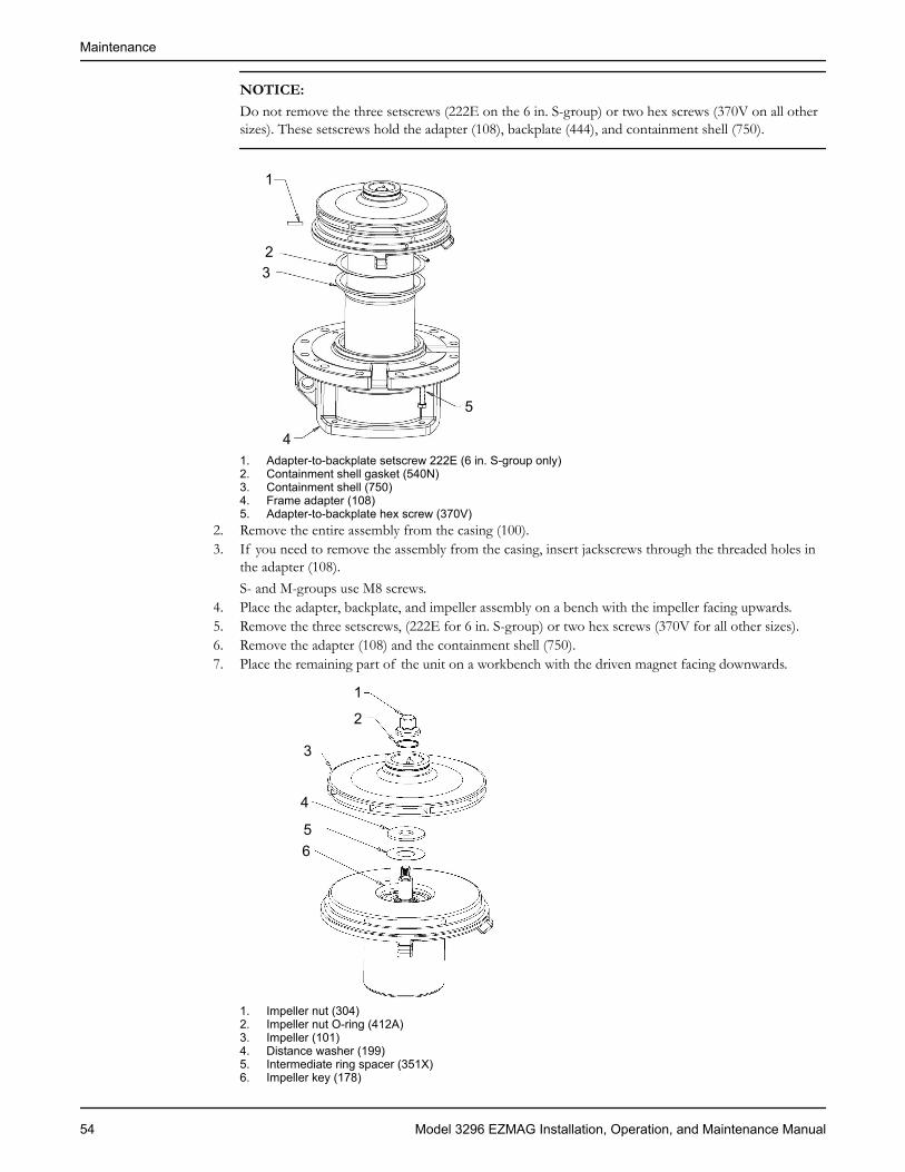
NOTICE:Do not remove the three setscrews (222E on the 6 in. S-group) or two hex screws (370V on all othersizes). These setscrews hold the adapter (108), backplate (444), and containment shell (750).
1
23
4
5
1. Adapter-to-backplate setscrew 222E (6 in. S-group only)2. Containment shell gasket (540N)3. Containment shell (750)4. Frame adapter (108)5. Adapter-to-backplate hex screw (370V)
2. Remove the entire assembly from the casing (100).3. If you need to remove the assembly from the casing, insert jackscrews through the threaded holes in
the adapter (108).S- and M-groups use M8 screws.
4. Place the adapter, backplate, and impeller assembly on a bench with the impeller facing upwards.5. Remove the three setscrews, (222E for 6 in. S-group) or two hex screws (370V for all other sizes).6. Remove the adapter (108) and the containment shell (750).7. Place the remaining part of the unit on a workbench with the driven magnet facing downwards.
1
2
3
4
56
1. Impeller nut (304)2. Impeller nut O-ring (412A)3. Impeller (101)4. Distance washer (199)5. Intermediate ring spacer (351X)6. Impeller key (178)
Maintenance
54 Model 3296 EZMAG Installation, Operation, and Maintenance Manual

8. Place the strap wrench on the impeller and remove the impeller nut (304) and O-ring (412A).9. Slide the impeller (101) off the shaft.10. Remove the impeller key (178), distance washer (199), and gasket (351X).11. Pull the backplate (444) and bearing cartridge (849) from the shaft.
12 3 4
5 61. Backplate (444)2. Cartridge-to-backplate hex screw (791E)3. Parallel pin (445A)4. Driven carrier assembly (740A)5. Bearing cartridge assembly (849)6. Intermediate ring spacer (351X)
12. Remove the second gasket (351X).13. Undo the screws (791E) and remove the bearing cartridge (849) from the backplate (444).
The driven magnet assembly (740A) is a two-piece assembly on S-group pumps held with a drive-key.Item 740A is a single-piece component on M-group pumps with a parallel pin (445A) to drive thebearing cartridge.The bearing cartridge (849) is one unit that is replaced completely.
Pre-assembly inspectionsGuidelines
Before you assemble the pump parts, make sure you follow these guidelines:• Inspect the pump parts according to the information in these pre-assembly topics before you
reassemble your pump. Replace any part that does not meet the required criteria.• Make sure that the parts are clean. Clean the pump parts in solvent in order to remove oil, grease, and
dirt.
NOTICE: Protect machined surfaces while you clean the parts. Failure to do so may result inequipment damage.
Replacement guidelinesCasing check and replacement
Inspect the casing for cracks and excessive wear or pitting. Thoroughly clean gasket surfaces and alignmentfits in order to remove rust and debris.Repair or replace the casing if you notice any of these conditions:
• Localized wear or grooving that is greater than 1/8 in. (3.2 mm) deep• Pitting that is greater than 1/8 in. (3.2 mm) deep• Irregularities in the casing-gasket seat surface
Casing areas to inspectThe arrows point to the areas to inspect for wear on the casing:
Maintenance
Model 3296 EZMAG Installation, Operation, and Maintenance Manual 55
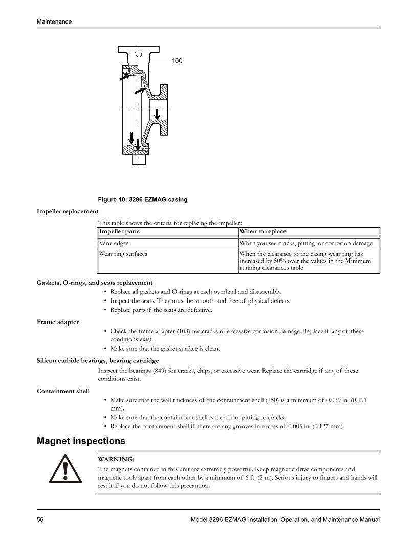
100
Figure 10: 3296 EZMAG casing
Impeller replacementThis table shows the criteria for replacing the impeller:Impeller parts When to replaceVane edges When you see cracks, pitting, or corrosion damageWear ring surfaces When the clearance to the casing wear ring has
increased by 50% over the values in the Minimumrunning clearances table
Gaskets, O-rings, and seats replacement• Replace all gaskets and O-rings at each overhaul and disassembly.• Inspect the seats. They must be smooth and free of physical defects.• Replace parts if the seats are defective.
Frame adapter• Check the frame adapter (108) for cracks or excessive corrosion damage. Replace if any of these
conditions exist.• Make sure that the gasket surface is clean.
Silicon carbide bearings, bearing cartridgeInspect the bearings (849) for cracks, chips, or excessive wear. Replace the cartridge if any of theseconditions exist.
Containment shell• Make sure that the wall thickness of the containment shell (750) is a minimum of 0.039 in. (0.991
mm).• Make sure that the containment shell is free from pitting or cracks.• Replace the containment shell if there are any grooves in excess of 0.005 in. (0.127 mm).
Magnet inspections
WARNING:The magnets contained in this unit are extremely powerful. Keep magnetic drive components andmagnetic tools apart from each other by a minimum of 6 ft. (2 m). Serious injury to fingers and hands willresult if you do not follow this precaution.
Maintenance
56 Model 3296 EZMAG Installation, Operation, and Maintenance Manual

Driven magnet assembly inspectionsPerform these checks on the driven magnet assembly (740A):
• Check that the assembly is free from bulges.• Check that the assembly is free from pits and scratches that exceed 0.005 in. (0.127 mm) deep.• Check that the assembly is free from erosion or corrosion that exceeds 0.005 in. (0.127 mm) deep.• Check the pump-out vanes for cracks and corrosion.• Check that the circulation holes are open.
Drive magnet assemblyThe magnets are extremely brittle. It is normal to have chips that amount to 10% of the magnet surfaceper MMPA Standard No. 0100-90.Perform these checks on the drive magnet assembly (740B):
• Check that the magnets are free of major cracks and extent over 50% of the surface and are free ofimperfections that create loose particles.
• Replace the magnets if the magnets and drive magnet carrier were exposed to any pumped fluid.• Check the drive magnet carrier for cracks and replace if any cracks are found.• Check the drive magnet carrier hub OD is free from grooves and scratches that are greater than 0.005
in. (0.127 mm).• Check the magnets for proper bonding to the metal carrier.
Bearing-frame inspectionChecklist
Check the bearing frame for these conditions:• Visually inspect the bearing frame and frame foot for cracks.• Check the inside surfaces of the frame for rust, scale, or debris. Remove all loose and foreign material.• Make sure that all lubrication passages are clear.• Inspect the inboard-bearing bores.
The maximum acceptable bore is 2.836 in. (7.203 cm) for S-group pumps and 3.544 in. (9.002 cm) forM-group pumps.
• Inspect the labyrinth seal O-rings for cuts and cracks.• Inspect the ball bearings for containment and damage.• Make sure the gasket surfaces are clean.• Visually inspect the bearing end cover for cracks and pits.
Bearings inspectionCondition of bearings
Do not reuse bearings. The condition of the bearings provides useful information on operating conditionsin the bearing frame.
ChecklistPerform these checks when you inspect the bearings:
• Inspect the ball bearings for contamination and damage.• Note any lubricant condition and residue.• Inspect the ball bearings to see if they are loose, rough, or noisy when you rotate them.• Inspect the silicon carbide bearings for cracks, chips, or excessive wear. If any of these conditions
exist, replace the bearing cartridge.• Investigate any bearing damage to determine the cause. If the cause is not normal wear, correct the
issue before you return the pump to service.
Minimum running clearancesThis table provides the radial wear ring clearances:
Maintenance
Model 3296 EZMAG Installation, Operation, and Maintenance Manual 57
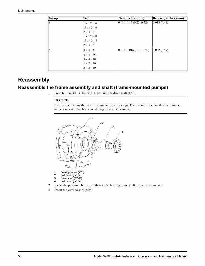
Group Size New, inches (mm) Replace, inches (mm)S 1 x 1½ - 6
1½ x 3 - 62 x 3 - 61 x 1½ - 81½ x 3 - 82 x 3 - 8
0.010–0.13 (0.25–0.32) 0.018 (0.44)
M 3 x 4 - 74 x 4 - 8G3 x 4 - 101 x 2 - 102 x 3 - 10
0.014–0.016 (0.35–0.42) 0.022 (0.59)
ReassemblyReassemble the frame assembly and shaft (frame-mounted pumps)
1. Press both radial ball bearings (112) onto the drive shaft (122B).
NOTICE:There are several methods you can use to install bearings. The recommended method is to use aninduction heater that heats and demagnetizes the bearings.
12
34
1. Bearing frame (228)2. Ball bearing (112)3. Drive shaft (122B)4. Ball bearing (112)
2. Install the pre-assembled drive shaft in the bearing frame (228) from the motor side.3. Insert the wave washer (529).
Maintenance
58 Model 3296 EZMAG Installation, Operation, and Maintenance Manual
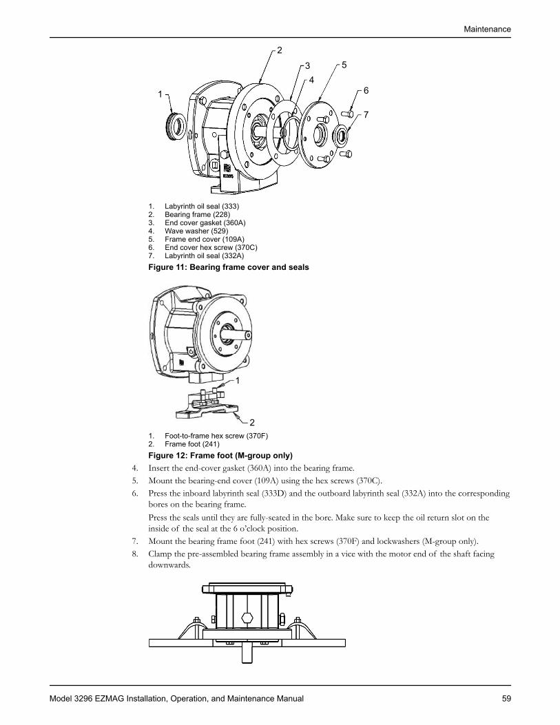
1
234
5
6
7
1. Labyrinth oil seal (333)2. Bearing frame (228)3. End cover gasket (360A)4. Wave washer (529)5. Frame end cover (109A)6. End cover hex screw (370C)7. Labyrinth oil seal (332A)Figure 11: Bearing frame cover and seals
1
21. Foot-to-frame hex screw (370F)2. Frame foot (241)Figure 12: Frame foot (M-group only)
4. Insert the end-cover gasket (360A) into the bearing frame.5. Mount the bearing-end cover (109A) using the hex screws (370C).6. Press the inboard labyrinth seal (333D) and the outboard labyrinth seal (332A) into the corresponding
bores on the bearing frame.Press the seals until they are fully-seated in the bore. Make sure to keep the oil return slot on theinside of the seal at the 6 o’clock position.
7. Mount the bearing frame foot (241) with hex screws (370F) and lockwashers (M-group only).8. Clamp the pre-assembled bearing frame assembly in a vice with the motor end of the shaft facing
downwards.
Maintenance
Model 3296 EZMAG Installation, Operation, and Maintenance Manual 59
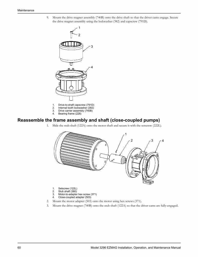
9. Mount the drive magnet assembly (740B) onto the drive shaft so that the driver cams engage. Securethe drive magnet assembly using the lockwasher (382) and capscrew (791D).
1
2
3
4
1. Drive-to-shaft capscrew (791D)2. Internal tooth lockwasher (382)3. Drive carrier assembly (740B)4. Bearing frame (228)
Reassemble the frame assembly and shaft (close-coupled pumps)1. Slide the stub shaft (122A) onto the motor shaft and secure it with the setscrew (222L).
1
2 3 4
1. Setscrew (122L)2. Stub shaft (380)3. Motor-to-adapter hex screw (371)4. Close-coupled adapter (503)
2. Mount the motor adapter (503) onto the motor using hex screws (371).3. Mount the drive magnet (740B) onto the stub shaft (122A) so that the driver cams are fully-engaged.
Maintenance
60 Model 3296 EZMAG Installation, Operation, and Maintenance Manual

1
2
34 5 6 7
8
1. Stub shaft–to-motor setscrew (222L)2. Stub shaft (380)3. Motor-to-adapter hex screw (371)4. Frame-to-adapter hex screw (370B)5. Close-coupled adapter (503)6. Frame-to-adapter gasket (360W)7. Drive carrier assembly (740B)8. Drive-to-shaft capscrew (791D), internal tooth lockwasher (382)
4. Insert the lockwasher (382) and capscrew (791D) in order to secure the magnet to the shaft.
12
3
1. Frame-to-adapter hex screw (370B)2. Close-coupled adapter (503)3. Frame-to-adapter gasket (360W)Figure 13: Close-coupled pump assembly
Reassemble the liquid end1. Insert the bearing cartridge (849) into the backplate (444).
Maintenance
Model 3296 EZMAG Installation, Operation, and Maintenance Manual 61
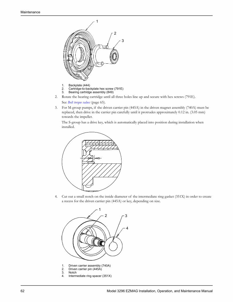
1
2
3
1. Backplate (444)2. Cartridge-to-backplate hex screw (791E)3. Bearing cartridge assembly (849)
2. Rotate the bearing cartridge until all three holes line up and secure with hex screws (791E).See Bolt torque values (page 65).
3. For M-group pumps, if the driven carrier pin (445A) in the driven magnet assembly (740A) must bereplaced, then drive in the carrier pin carefully until it protrudes approximately 0.12 in. (3.05 mm)towards the impeller.The S-group has a drive key, which is automatically placed into position during installation wheninstalled.
4. Cut out a small notch on the inside diameter of the intermediate ring gasket (351X) in order to createa recess for the driven carrier pin (445A) or key, depending on size.
12
4
3
1. Driven carrier assembly (740A)2. Driven carrier pin (445A)3. Notch4. Intermediate ring spacer (351X)
Maintenance
62 Model 3296 EZMAG Installation, Operation, and Maintenance Manual
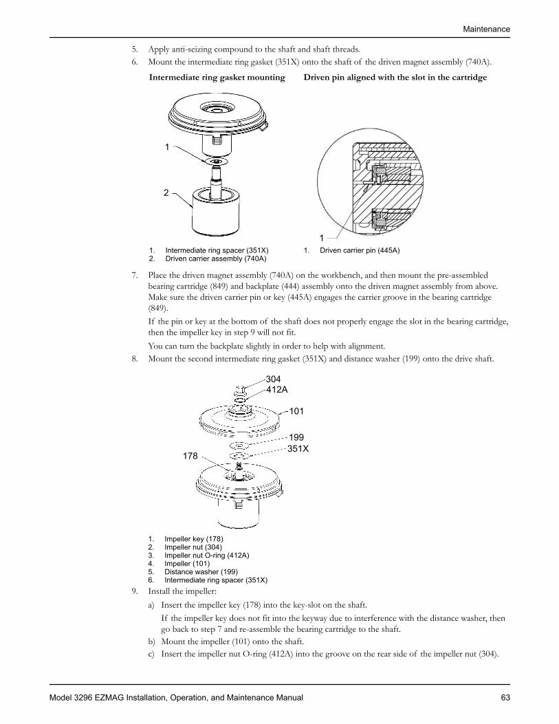
5. Apply anti-seizing compound to the shaft and shaft threads.6. Mount the intermediate ring gasket (351X) onto the shaft of the driven magnet assembly (740A).
Intermediate ring gasket mounting Driven pin aligned with the slot in the cartridge
1
2
1. Intermediate ring spacer (351X)2. Driven carrier assembly (740A)
11. Driven carrier pin (445A)
7. Place the driven magnet assembly (740A) on the workbench, and then mount the pre-assembledbearing cartridge (849) and backplate (444) assembly onto the driven magnet assembly from above.Make sure the driven carrier pin or key (445A) engages the carrier groove in the bearing cartridge(849).If the pin or key at the bottom of the shaft does not properly engage the slot in the bearing cartridge,then the impeller key in step 9 will not fit.You can turn the backplate slightly in order to help with alignment.
8. Mount the second intermediate ring gasket (351X) and distance washer (199) onto the drive shaft.
178
304412A
101
199351X
1. Impeller key (178)2. Impeller nut (304)3. Impeller nut O-ring (412A)4. Impeller (101)5. Distance washer (199)6. Intermediate ring spacer (351X)
9. Install the impeller:a) Insert the impeller key (178) into the key-slot on the shaft.
If the impeller key does not fit into the keyway due to interference with the distance washer, thengo back to step 7 and re-assemble the bearing cartridge to the shaft.
b) Mount the impeller (101) onto the shaft.c) Insert the impeller nut O-ring (412A) into the groove on the rear side of the impeller nut (304).
Maintenance
Model 3296 EZMAG Installation, Operation, and Maintenance Manual 63
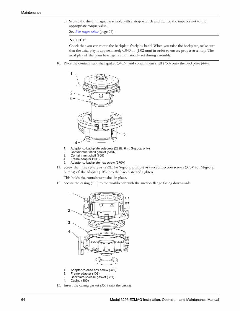
d) Secure the driven magnet assembly with a strap wrench and tighten the impeller nut to theappropriate torque value.See Bolt torque values (page 65).
NOTICE:Check that you can rotate the backplate freely by hand. When you raise the backplate, make surethat the axial play is approximately 0.040 in. (1.02 mm) in order to ensure proper assembly. Theaxial play of the plain bearings is automatically set during assembly.
10. Place the containment shell gasket (540N) and containment shell (750) onto the backplate (444).
1
23
4
5
1. Adapter-to-backplate setscrew (222E, 6 in. S-group only)2. Containment shell gasket (540N)3. Containment shell (750)4. Frame adapter (108)5. Adapter-to-backplate hex screw (370V)
11. Screw the three setscrews (222E for S-group pumps) or two connection screws (370V for M-grouppumps) of the adapter (108) into the backplate and tighten.This holds the containment shell in place.
12. Secure the casing (100) to the workbench with the suction flange facing downwards.
1
2
3
4
1. Adapter-to-case hex screw (370)2. Frame adapter (108)3. Backplate-to-case gasket (351)4. Casing (100)
13. Insert the casing gasket (351) into the casing.
Maintenance
64 Model 3296 EZMAG Installation, Operation, and Maintenance Manual

14. Insert the pre-assembled unit into the casing so that the crane hook of the adapter (108) faces thecenter of the discharge nozzle.
15. Secure the adapter to the casing using hex screws (370) to the appropriate torque value.See Bolt torque values (page 65).
Complete the pump reassembly1. Insert the gasket (360W) into the adapter.
1
2
3
4
5
1. Frame-to-adapter hex screw (370B)2. Frame assembly3. Mag drive carrier4. Frame-to-adapter gasket (360W)5. Adapter
2. Secure the bearing frame and drive magnet assembly:a) Place the bearing frame and drive magnet assembly already assembled on the workbench with the
drive magnet facing downwards.b) Screw a 3/8 in. eyebolt into the end of the drive shaft.c) Place the bearing frame assembly onto the adapter using a crane.d) Screw in the hex screws (370B) in order to secure the bearing frame to the adapter.e) Turn the drive shaft by hand to make sure that the shaft can rotate freely.
Check by looking into the suction nozzle to make sure the impeller is rotating.
Bolt torque valuesNOTICE:Make sure to tighten in a diametrically opposite sequence.
Description Group Dry, ft-lbs (Nm) Standard lube, ft-lbs(Nm)
Adapter to casing screws(370)
S/M (M12) 65 (88) 49 (66)10 in. M (M16) 161 (219) 120 (164)
Impeller nut (304) S 47 (64) 26 (35)M 116 (158) 52 (70)
Maintenance
Model 3296 EZMAG Installation, Operation, and Maintenance Manual 65

Description Group Dry, ft-lbs (Nm) Standard lube, ft-lbs(Nm)
Cartridge to backplatescrews (791E)
S/M 12 (16) 9 (12)
Maintenance
66 Model 3296 EZMAG Installation, Operation, and Maintenance Manual

TroubleshootingOperation troubleshootingSymptom Cause RemedyThe pump is not delivering liquid. The pump is not primed. Reprime the pump and check that the
pump and suction line are full of liquid.The suction line is clogged. Check the suction line pressure. If it is
low, locate and remove any obstructions.The impeller is clogged. Disassemble the impeller and remove the
blockage.The magnet is de-coupling. Shut down the pump and check the
temperature and viscosity of the pumpedfluid. Check the magnets with a breakawaytorque test.
The pump is not producing rated flow orhead.
There is an air leak in the suction line. Check for leaks and repair the lines.The impeller is partly clogged. Back flush the pump to clean the impeller.The impeller rings are worn. Replace the defective ring as required.There is insufficient suction head. Make sure that the suction line shutoff
valve is fully open and the line isunobstructed. Check the suction pressure.
The impeller is either worn or broken. Inspect and replace the impeller ifnecessary.
The rotation is wrong. Correct the wiring.Pump starts and then stops pumping. The pump is not primed correctly. Reprime the pump.
There is an air leak in the suction line. Check for leaks and correct.The magnet is de-coupling. Shut down the pump. Check the
temperature and viscosity of the pumpedfluid. Check the magnets with a breakawaytorque test.
There are either air or vapor pockets inthe suction line.
Rearrange the piping to eliminate airpockets.
The bearings run hot. The bearings are not lubricated properly. Check the suitability and level of thelubricant.
The lubricant is cooling. Check the cooling system.The pump is not aligned properly. Check the pump alignment.
Pump is noisy or vibrates. The pump or driver is not alignedproperly.
Align the shafts.
There is a partially-clogged impellercausing the imbalance.
Disassemble the impeller and remove theblockage.
There is a broken or bent impeller orshaft.
Replace as required.
The base is not rigid enough. Tighten the pump and motor hold-downbolts or adjust the stilts. Then check thegrout.
The suction or discharge piping is notanchored or properly supported.
Anchor the piping per the HydraulicInstitute Standards recommendations(Edition 14, centrifugal pump section).
The pump is cavitating. Increase the NPSH available.
Troubleshooting
Model 3296 EZMAG Installation, Operation, and Maintenance Manual 67

Symptom Cause RemedyThe motor requires excessive power. The head is lower than the rating and the
pump has too much liquid.Install a throttle valve.
The liquid is heavier than expected. Check the specific gravity and viscosity.The head is higher than the rating, whichis at capacity.
Check the impeller diameter.
The rotating parts are binding or areseverely worn.
Check the internal wearing parts forproper clearances.
The motor rotation is incorrect. Correct the wiring.The condition monitoring device shutsdown the pump.
The sleeve and thrust bearings aredamaged.
Replace as required.
There is a plugged recirculation circuit. Disassemble and remove the blockage.Then determine and correct the cause ofthe blockage.
There is recirculation liquid vaporization. Correct all of these as necessary:• Check the actual liquid temperature
versus the design temperature.• Check the actual NPSH available
versus the design.• Check the minimum flow
requirement for the pump size.
The containment shell is damaged. Replace as required.The magnets are de-coupling. Check the temperature and viscosity of
the pumped fluid. Check the magnets witha breakaway torque test.
The pump is running dry. • Check the control device for properoperation.
• Check the suction line for blockage.• Reprime the pump.
There is excessive motor power. The system head is lower than the ratingand pumps too much liquid.Check the rotating parts for binding andwear. The liquid is heavier than expected.
Alignment troubleshootingSymptom Cause RemedyHorizontal (side-to-side) alignment cannotbe obtained (angular or parallel).
The driver feet are bolt-bound. Loosen the pump's hold-down bolts, andslide the pump and driver until youachieve horizontal alignment.
The baseplate is not leveled properly andis probably twisted.
1. Determine which corners of thebaseplate are high or low.
2. Remove or add shims at theappropriate corners.
3. Realign the pump and driver.Vertical (top-to-bottom) alignment cannotbe obtained (angular or parallel).
The baseplate is not leveled properly andis probably bowed.
1. Determine if the center of thebaseplate should be raised or lowered.
2. Level screws equally at the center ofthe baseplate.
3. Realign the pump and driver.
Troubleshooting
68 Model 3296 EZMAG Installation, Operation, and Maintenance Manual

Parts Listings and Cross-SectionalDrawingsClose-coupled S-group (all) and M-group (2 x 3 - 8 only) —stainless steelCross-sectional drawing
371 492A 503 791D 178X 122A 108 370V 791E 222E100
199
178
412A
304
101
351X
540N351444370849740B351X360W740A
750
382
380
222L
Parts listItem Quantity Part name Material100 1 Casing Stainless steel (1.4408)101 1 Impeller Stainless steel (1.4408)108 1 Frame adapter Ductile iron122A* 1 Driven shaft Duplex SS (1.4462)178 1 Impeller key 303SS178X* 1 Driven carrier key Stainless steel (1.4571)199 1 Distance washer Stainless steel (1.4571)
Parts Listings and Cross-Sectional Drawings
Model 3296 EZMAG Installation, Operation, and Maintenance Manual 69

Item Quantity Part name Material222E 3 Adapter-to-backplate setscrew (6 in. size
pumps)Steel
222L 2 Stub shaft–to-motor setscrew Steel304 1 Impeller nut Duplex SS (1.4517)351 1 Backplate-to-case gasket Optional gasket material:
• Aramid fiber/EPDM (standard)• White gylon (optional)• Fawn gylon (optional)
351X 2 Intermediate ring spacer Optional spacer material:• TFM1600 (PTFE) (standard)• Viton B (optional)
360W 1 Frame-to-adapter gasket Aramid fiber/EPDM370 8 for 6 in. pumps, 12
for 8 in. pumpsAdapter-to-case hex capscrew Steel
370B 4 Frame-to-adapter hex capscrew (notillustrated)
Steel
370V 2 Adapter-to-backplate hex capscrew (8 in.pumps)
Steel
371 4 Motor-to-adapter hex capscrew Steel380 1 Stub shaft Steel382 1 Internal tooth lockwasher Steel412A 1 Impeller nut O-ring Teflon444 1 Backplate Stainless steel (1.4408)492A 1 Frame plug, setscrew access Steel503 1 Close-coupled adapter Cast iron540N 1 Containment shell gasket Optional gasket material:
• Aramid fiber/EPDM (standard)• White gylon (optional)• Fawn gylon (optional)
740A 1 Driven carrier assembly Duplex SS/NdFeB (1.4517)740B 1 Drive carrier assembly Ductile iron/NdFeB (0.7043)750 1 Containment shell Hastelloy-C (2.4610)791D 1 Drive-to-shaft capscrew socket head Steel791E 3 Cartridge-to-backplate hex capscrew Stainless steel849 1 Bearing cartridge assembly Duplex SS/SSiC
Silicon Carbide (standard)Dryguard Silicon Carbide (optional)
High temperature optional components351 1 Backplate-to-case gasket Grafoil540N 1 Containment shell gasket Grafoil740A 1 Driven carrier assembly Duplex SS/SmCo (1.4517)740B 1 Drive carrier assembly Ductile iron/SmCo (0.7043)849 1 High temperature bearing cartridge
assemblyDuplex SS/SSiC
Silicon Carbide (standard)Dryguard Silicon Carbide (optional)
*Included in 740A driven carrier assembly.
Parts Listings and Cross-Sectional Drawings
70 Model 3296 EZMAG Installation, Operation, and Maintenance Manual
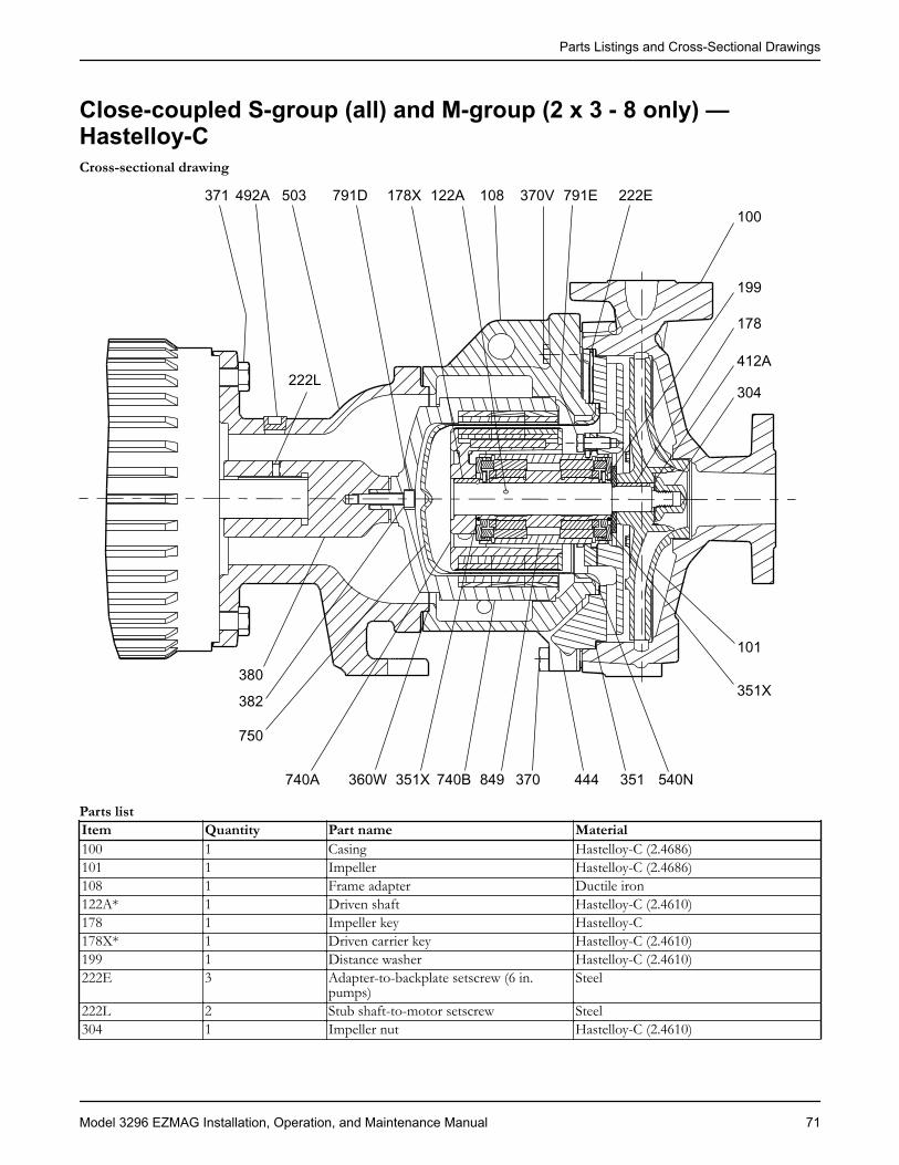
Close-coupled S-group (all) and M-group (2 x 3 - 8 only) —Hastelloy-CCross-sectional drawing
371 492A 503 791D 178X 122A 108 370V 791E 222E100
199
178
412A
304222L
101
351X
540N351444370849740B351X360W740A
750
382
380
Parts listItem Quantity Part name Material100 1 Casing Hastelloy-C (2.4686)101 1 Impeller Hastelloy-C (2.4686)108 1 Frame adapter Ductile iron122A* 1 Driven shaft Hastelloy-C (2.4610)178 1 Impeller key Hastelloy-C178X* 1 Driven carrier key Hastelloy-C (2.4610)199 1 Distance washer Hastelloy-C (2.4610)222E 3 Adapter-to-backplate setscrew (6 in.
pumps)Steel
222L 2 Stub shaft-to-motor setscrew Steel304 1 Impeller nut Hastelloy-C (2.4610)
Parts Listings and Cross-Sectional Drawings
Model 3296 EZMAG Installation, Operation, and Maintenance Manual 71

Item Quantity Part name Material351 1 Backplate-to-case gasket Optional gasket material:
• Aramid fiber/EPDM (standard)• White gylon (optional)• Fawn gylon (optional)
351X 2 Intermediate ring spacer Optional spacer material:• TFM1600 (PTFE) (standard)• Viton B (optional)
360W 1 Frame-to-adapter gasket Aramid fiber/EPDM370 8 for 6 in. pumps, 12
for 8 in. pumpsAdapter-to-case hex capscrew Steel
370B 4 Frame-to-adapter hex capscrew (notillustrated)
Steel
370V 2 Adapter-to-backplate hex capscrew (8 in.pumps)
Steel
371 4 Motor-to-adapter hex capscrew Steel380 1 Stub shaft Steel382 1 Internal tooth lockwasher Stainless steel412A 1 Impeller nut O-ring Teflon444 1 Backplate Hastelloy-C (2.4686)492A 1 Frame plug, setscrew access Steel503 1 Close-coupled adapter Cast iron540N 1 Containment shell gasket Optional gasket material:
• Aramid fiber/EPDM (standard)• White gylon (optional)• Fawn gylon (optional)
740A 1 Driven carrier assembly Hastelloy-C/NdFeB (2.4686)740B 1 Drive carrier assembly Ductile iron/NdFeB (0.7043)750 1 Containment shell Hastelloy-C (2.4610)791D 1 Drive-to-shaft capscrew socket head Steel791E 3 Cartridge-to-backplate hex capscrew Hastelloy-C849 1 Bearing cartridge assembly Hastelloy-C/SSiC
Silicon Carbide (standard)Dryguard Silicon Carbide (optional)
High temperature optional components351 1 Backplate-to-case gasket Grafoil540N 1 Containment shell gasket Grafoil740A 1 Driven carrier assembly Hastelloy-C/SmCo (2.4686)740B 1 Drive carrier assembly Ductile iron/SmCo (0.7043)849 1 High temperature bearing cartridge
assemblyHastelloy-C/SSiC
Silicon Carbide (standard)Dryguard Silicon Carbide (optional)
*Included in 740A driven carrier assembly.
Parts Listings and Cross-Sectional Drawings
72 Model 3296 EZMAG Installation, Operation, and Maintenance Manual

S-group with bearing frame — stainless steelCross-sectional drawing
113A 333D 382 370B 791D178X 122A
740B 108 370V 791E 222E 351 540N
100
199
178
412A
304
101
351X
444370849351X740A360W750408A
319112
360A
529
370C
400
122B
332A
109A
228
Parts listItem Quantity Part name Material100 1 Casing Stainless steel (1.4408)101 1 Impeller Stainless steel (1.4408)108 1 Frame adapter Ductile iron109A 1 Frame end cover Ductile iron112 2 Ball bearing Steel113A 1 Fill plug Steel122A* 1 Driven shaft Duplex SS (1.4462)122B 1 Drive shaft Steel 4140178 1 Impeller key 303SS178* 1 Driven carrier key Stainless steel (1.4571)199 1 Distance washer Stainless steel (1.4571)222E 3 Adapter-to-backplate setscrew (6 in.
pumps)Steel
228 1 Bearing frame Cast iron
Parts Listings and Cross-Sectional Drawings
Model 3296 EZMAG Installation, Operation, and Maintenance Manual 73

Item Quantity Part name Material304 1 Impeller nut Duplex SS (1.4517)319 1 Sight window Steel/glass332A 1 Labyrinth oil seal (coupling end) Bronze/SS333D 1 Labyrinth oil seal (radial end) Carbon-filled Teflon351 1 Backplate-to-case gasket Optional gasket material:
• Aramid fiber/EPDM (standard)• White gylon (optional)• Fawn gylon (optional)
351X 2 Intermediate ring spacer Optional spacer material:• TFM1600 (PTFE) (standard)• Viton B (optional)
360A 1 End cover gasket Vellumiod360W 1 Frame-to-adapter gasket Aramid fiber/EPDM370 8 for 6 in. pumps, 12
for 8 in. pumpsAdapter-to-case hex capscrew Steel
370B 4 Frame-to-adapter hex capcrew Steel370C 1 End cover hex capscrew Steel370V 2 Adapter-to-backplate hex capscrew (8 in.
pumps)Steel
382 1 Internal tooth lockwasher Stainless steel370C 4 End cover hex capscrew Steel400 1 Coupling key Steel408A 1 Drain plug Steel412A 1 Impeller nut O-ring Teflon444 1 Backplate Stainless steel (1.4408)529 1 Wave washer Steel540N 1 Containment shell gasket Optional gasket material:
• Aramid fiber/EPDM (standard)• White gylon (optional)• Fawn gylon (optional)
740A 1 Driven carrier assembly Duplex SS/NdFeB (1.4517)740B 1 Drive carrier assembly Ductile iron/NdFeB (0.7043)750 1 Containment shell Hastelloy-C (2.4610)791D 1 Drive-to-shaft capscrew socket head Steel791E 3 Cartridge-to-backplate hex capscrew Stainless steel849 1 Bearing cartridge assembly Duplex SS/SSiC
Silicon Carbide (standard)Dryguard Silicon Carbide (optional)
High temperature optional components351 1 Backplate-to-case gasket Grafoil540N 1 Containment shell gasket Grafoil740A 1 Driven carrier assembly Duplex SS/SmCo (1.4517)740B 1 Drive carrier assembly Ductile iron/SmCo (0.7043)849 1 High temperature bearing cartridge
assemblyDuplex SS/SSiC
Silicon Carbide (standard)Dryguard Silicon Carbide (optional)
*Included in 740A driven carrier assembly.
Parts Listings and Cross-Sectional Drawings
74 Model 3296 EZMAG Installation, Operation, and Maintenance Manual
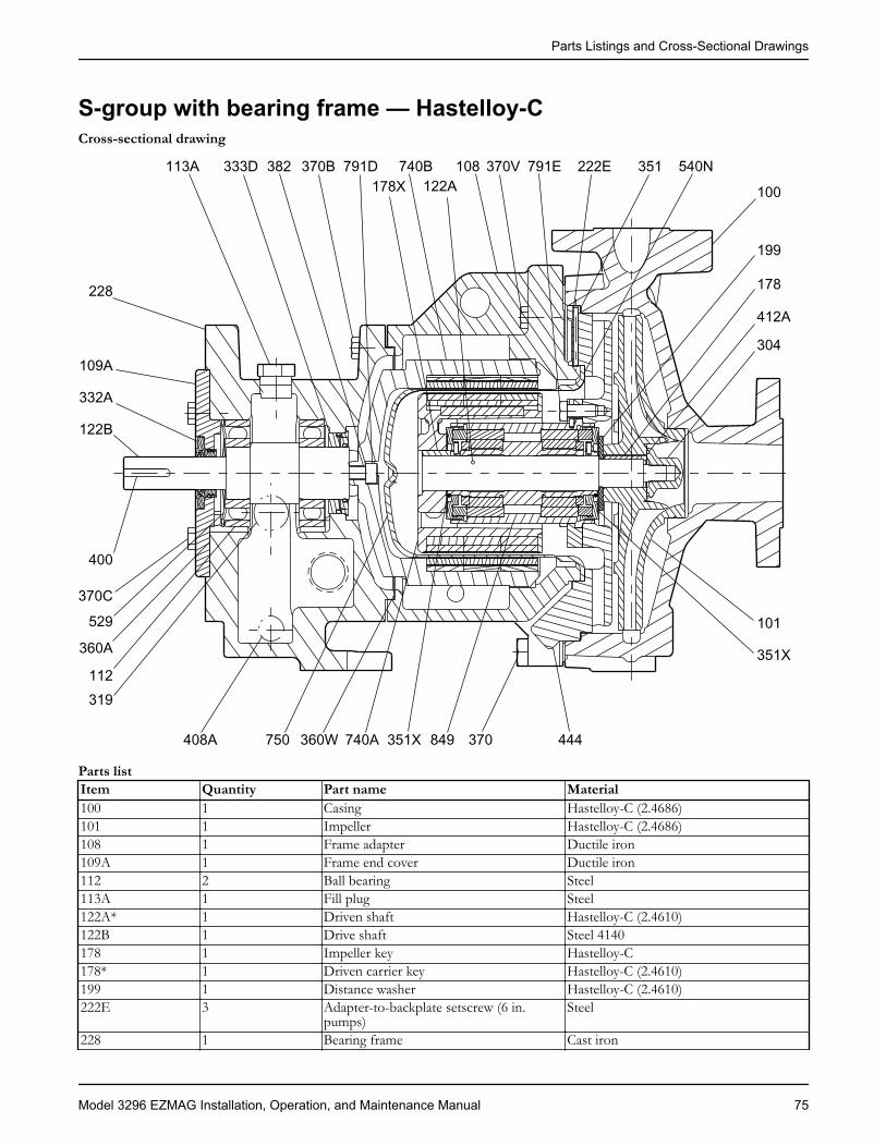
S-group with bearing frame — Hastelloy-CCross-sectional drawing
113A 333D 382 370B 791D178X 122A
740B 108 370V 791E 222E 351 540N
100
199
178
412A
304
101
351X
444370849351X740A360W750408A
319112
360A
529
370C
400
122B
332A
109A
228
Parts listItem Quantity Part name Material100 1 Casing Hastelloy-C (2.4686)101 1 Impeller Hastelloy-C (2.4686)108 1 Frame adapter Ductile iron109A 1 Frame end cover Ductile iron112 2 Ball bearing Steel113A 1 Fill plug Steel122A* 1 Driven shaft Hastelloy-C (2.4610)122B 1 Drive shaft Steel 4140178 1 Impeller key Hastelloy-C178* 1 Driven carrier key Hastelloy-C (2.4610)199 1 Distance washer Hastelloy-C (2.4610)222E 3 Adapter-to-backplate setscrew (6 in.
pumps)Steel
228 1 Bearing frame Cast iron
Parts Listings and Cross-Sectional Drawings
Model 3296 EZMAG Installation, Operation, and Maintenance Manual 75

Item Quantity Part name Material304 1 Impeller nut Hastelloy-C (2.4610)319 1 Sight window Steel/glass332A 1 Labyrinth oil seal (coupling end) Bronze/SS333D 1 Labyrinth oil seal (radial end) Carbon-filled Teflon351 1 Backplate-to-case gasket Optional gasket material:
• Aramid fiber/EPDM (standard)• White gylon (optional)• Fawn gylon (optional)
351X 2 Intermediate ring spacer Optional spacer material:• TFM1600 (PTFE) (standard)• Viton B (optional)
360A 1 End cover gasket Vellumiod360W 1 Frame-to-adapter gasket Aramid fiber/EPDM370 8 for 6 in. pumps, 12
for 8 in. pumpsAdapter-to-case hex capscrew Steel
370B 4 Frame-to-adapter hex capscrew Steel370C 4 End cover hex capscrew Steel370V 2 Adapter-to-backplate hex capscrew (8 in.
pumps)Steel
382 1 Internal tooth lockwasher Stainless steel400 1 Coupling key Steel408A 1 Drain plug Steel412A 1 Impeller nut O-ring Teflon444 1 Backplate Hastelloy-C (2.4686)529 1 Wave washer Steel540N 1 Containment shell gasket Optional gasket material:
• Aramid fiber/EPDM (standard)• White gylon (optional)• Fawn gylon (optional)
740A 1 Driven carrier assembly Hastelloy/NdFeB (1.4517)740B 1 Drive carrier assembly Ductile iron/NdFeB (0.7043)750 1 Containment shell Hastelloy-C (2.4610)791D 1 Drive-to-shaft capscrew socket head Steel791E 3 Cartridge-to-backplate hex capscrew Hastelloy-C849 1 Bearing cartridge assembly Hastelloy-C/SSiC
Silicon Carbide (standard)Dryguard Silicon Carbide (optional)
High temperature optional components351 1 Backplate-to-case gasket Grafoil540N 1 Containment shell gasket Grafoil740A 1 Driven carrier assembly Hastelloy-C/SmCo (2.4686)740B 1 Drive carrier assembly Ductile iron/SmCo (0.7043)849 1 High temperature bearing cartridge
assemblyHastelloy-C/SSiC
Silicon Carbide (standard)Dryguard Silicon Carbide (optional)
*Included in 740A driven carrier assembly.
Parts Listings and Cross-Sectional Drawings
76 Model 3296 EZMAG Installation, Operation, and Maintenance Manual

Frame cooling optionsCross-sectional drawing
555C
555B
551D 494 551D
555B
555C
Parts listItem Quantity Part name Material494 2 Cooling tube Stainless steel555B 2 Thermocouple fitting tube Stainless steel555C 2 Tube fitting str Brass551D 1 Hex bushing Iron
Parts Listings and Cross-Sectional Drawings
Model 3296 EZMAG Installation, Operation, and Maintenance Manual 77
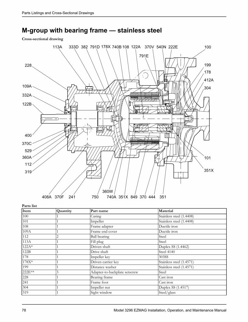
M-group with bearing frame — stainless steelCross-sectional drawing
113A 333D 382 791D 178X 122A740B 108 370V
791E
222E540N 100
199178
412A
304
101
351X
444370849351X740A360W
750408A
319
112360A
529
370C
400
122B
332A
109A
228
370F 241 351
Parts listItem Quantity Part name Material100 1 Casing Stainless steel (1.4408)101 1 Impeller Stainless steel (1.4408)108 1 Frame adapter Ductile iron109A 1 Frame end cover Ductile iron112 2 Ball bearing Steel113A 1 Fill plug Steel122A* 1 Driven shaft Duplex SS (1.4462)122B 1 Drive shaft Steel 4140178 1 Impeller key 303SS178X* 1 Driven carrier key Stainless steel (1.4571)199 1 Distance washer Stainless steel (1.4571)222E** 3 Adapter-to-backplate setscrew Steel228 1 Bearing frame Cast iron241 1 Frame foot Cast iron304 1 Impeller nut Duplex SS (1.4517)319 1 Sight window Steel/glass
Parts Listings and Cross-Sectional Drawings
78 Model 3296 EZMAG Installation, Operation, and Maintenance Manual
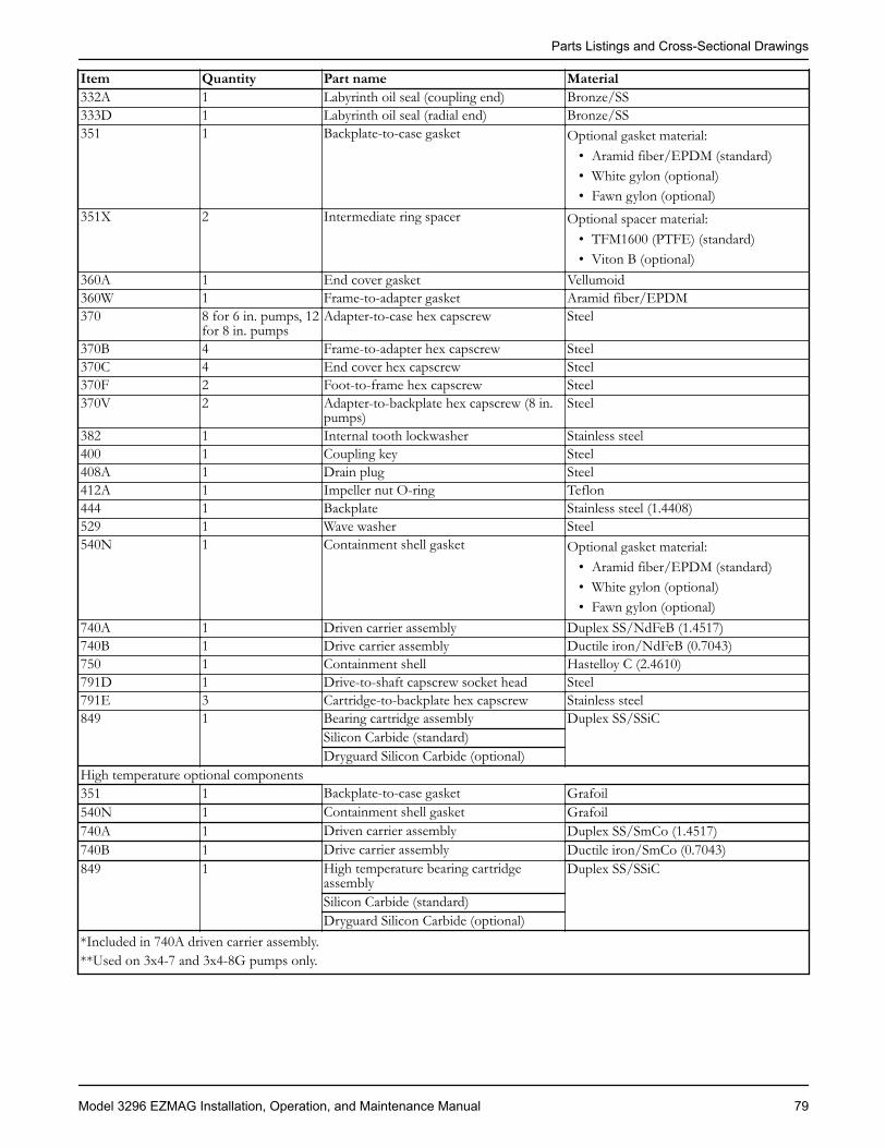
Item Quantity Part name Material332A 1 Labyrinth oil seal (coupling end) Bronze/SS333D 1 Labyrinth oil seal (radial end) Bronze/SS351 1 Backplate-to-case gasket Optional gasket material:
• Aramid fiber/EPDM (standard)• White gylon (optional)• Fawn gylon (optional)
351X 2 Intermediate ring spacer Optional spacer material:• TFM1600 (PTFE) (standard)• Viton B (optional)
360A 1 End cover gasket Vellumoid360W 1 Frame-to-adapter gasket Aramid fiber/EPDM370 8 for 6 in. pumps, 12
for 8 in. pumpsAdapter-to-case hex capscrew Steel
370B 4 Frame-to-adapter hex capscrew Steel370C 4 End cover hex capscrew Steel370F 2 Foot-to-frame hex capscrew Steel370V 2 Adapter-to-backplate hex capscrew (8 in.
pumps)Steel
382 1 Internal tooth lockwasher Stainless steel400 1 Coupling key Steel408A 1 Drain plug Steel412A 1 Impeller nut O-ring Teflon444 1 Backplate Stainless steel (1.4408)529 1 Wave washer Steel540N 1 Containment shell gasket Optional gasket material:
• Aramid fiber/EPDM (standard)• White gylon (optional)• Fawn gylon (optional)
740A 1 Driven carrier assembly Duplex SS/NdFeB (1.4517)740B 1 Drive carrier assembly Ductile iron/NdFeB (0.7043)750 1 Containment shell Hastelloy C (2.4610)791D 1 Drive-to-shaft capscrew socket head Steel791E 3 Cartridge-to-backplate hex capscrew Stainless steel849 1 Bearing cartridge assembly Duplex SS/SSiC
Silicon Carbide (standard)Dryguard Silicon Carbide (optional)
High temperature optional components351 1 Backplate-to-case gasket Grafoil540N 1 Containment shell gasket Grafoil740A 1 Driven carrier assembly Duplex SS/SmCo (1.4517)740B 1 Drive carrier assembly Ductile iron/SmCo (0.7043)849 1 High temperature bearing cartridge
assemblyDuplex SS/SSiC
Silicon Carbide (standard)Dryguard Silicon Carbide (optional)
*Included in 740A driven carrier assembly.**Used on 3x4-7 and 3x4-8G pumps only.
Parts Listings and Cross-Sectional Drawings
Model 3296 EZMAG Installation, Operation, and Maintenance Manual 79

M-group with bearing frame — Hastelloy-CCross-sectional drawing
113A 333D 382 791D 178X 122A740B 108 370V
791E
222E540N 100
199178
412A
304
101
351X
444370849351X740A360W
750408A
319
112360A
529
370C
400
122B
332A
109A
228
370F 241 351
Parts listItem Quantity Part name Material100 1 Casing Hastelloy-C (2.4686)101 1 Impeller Hastelloy-C (2.4686)108 1 Frame adapter Ductile iron109A 1 Frame end cover Ductile iron112 2 Ball bearing Steel113A 1 Fill plug Steel122A* 1 Driven shaft Hastelloy-C (2.4610)122B 1 Drive shaft Steel 4140178 1 Impeller key Hastelloy-C178X* 1 Driven carrier key Hastelloy-C (2.4610)199 1 Distance washer Hastelloy-C (2.4610)222E 3 Adapter-to-backplate setscrew (6 in.
pumps)Steel
228 1 Bearing frame Cast iron241 1 Frame foot Cast iron304 1 Impeller nut Hastelloy-C (2.4610)
Parts Listings and Cross-Sectional Drawings
80 Model 3296 EZMAG Installation, Operation, and Maintenance Manual

Item Quantity Part name Material319 1 Sight window Steel/glass332A 1 Labyrinth oil seal (coupling end) Bronze/SS333D 1 Labyrinth oil seal (radial end) Bronze/SS351 1 Backplate-to-case gasket Optional gasket material:
• Aramid fiber/EPDM (standard)• White gylon (optional)• Fawn gylon (optional)
351X 2 Intermediate ring spacer Optional spacer material:• TFM1600 (PTFE) (standard)• Viton B (optional)
360A 1 End cover gasket Vellumiod360W 1 Frame-to-adapter gasket Aramid fiber/EPDM370 8 for 6 in. pumps, 12
for 8 in. pumpsAdapter-to-case hex capscrew Steel
370B 4 Frame-to-adapter hex capscrew Steel370C 4 End cover hex capscrew Steel370F 2 Foot-to-frame hex capscrew Steel370V 2 Adapter-to-backplate hex capscrew
(except on 3x4-7 and 3x4-8G)Steel
382 1 Internal tooth lockwasher Stainless steel400 1 Coupling key Steel408A 1 Drain plug Steel412A 1 Impeller nut O-ring Teflon444 1 Backplate Hastelloy-C (2.4686)529 1 Wave washer Steel540N 1 Containment shell gasket Optional gasket material:
• Aramid fiber/EPDM (standard)• White gylon (optional)• Fawn gylon (optional)
740A 1 Driven carrier assembly Hastelloy-C/NdFeB (2.4686)740B 1 Drive carrier assembly Ductile iron/NdFeB (0.7043)750 1 Containment shell Hastelloy-C (2.4610)791D 1 Drive-to-shaft capscrew socket head Steel791E 3 Cartridge-to-backplate hex capscrew Hastelloy-C849 1 Bearing cartridge assembly Hastelloy-C/SSiC
Silicon Carbide (standard)Dryguard Silicon Carbide (optional)
High temperature optional components351 1 Backplate-to-case gasket Grafoil540N 1 Containment shell gasket Grafoil740A 1 Driven carrier assembly Hastelloy-C/SmCo (2.4686)740B 1 Drive carrier assembly Ductile iron/SmCo (0.7043)849 1 High temperature bearing cartridge
assemblyHastelloy-C/SSiC
Silicon Carbide (standard)Dryguard Silicon Carbide (optional)
*Included in 740A driven carrier assembly.
Parts Listings and Cross-Sectional Drawings
Model 3296 EZMAG Installation, Operation, and Maintenance Manual 81

Spare and repair partsRecommended spare parts
Item Quantity Part Material351 1 Backplate to case gasket Aramid fiber with EPDM rubber112 2 Ball bearing Steel351X 2 Intermediate ring spacer Grafoil360A 1 End-cover gasket Vellumoid360W 1 Frame-to-adapter gasket Aramid fiber with EPDM rubber740A 1 Driven carrier assembly Duplex SS/NdFeB740B 1 Drive carrier assembly Ductile iron/NdFeB750 1 Containment shell Hastelloy-C849 1 Bearing cartridge assembly Duplex SS/SSiC
Repair parts• Impeller (101)• Impeller nut and O-ring (304 and 412A)• Impeller key (178)• Driven magnet assembly (740A)• Drive magnet assembly (740B)• Containment shell (750)• Driven shaft (122B)• Labyrinth oil seals (332A and 333D)
Parts Listings and Cross-Sectional Drawings
82 Model 3296 EZMAG Installation, Operation, and Maintenance Manual
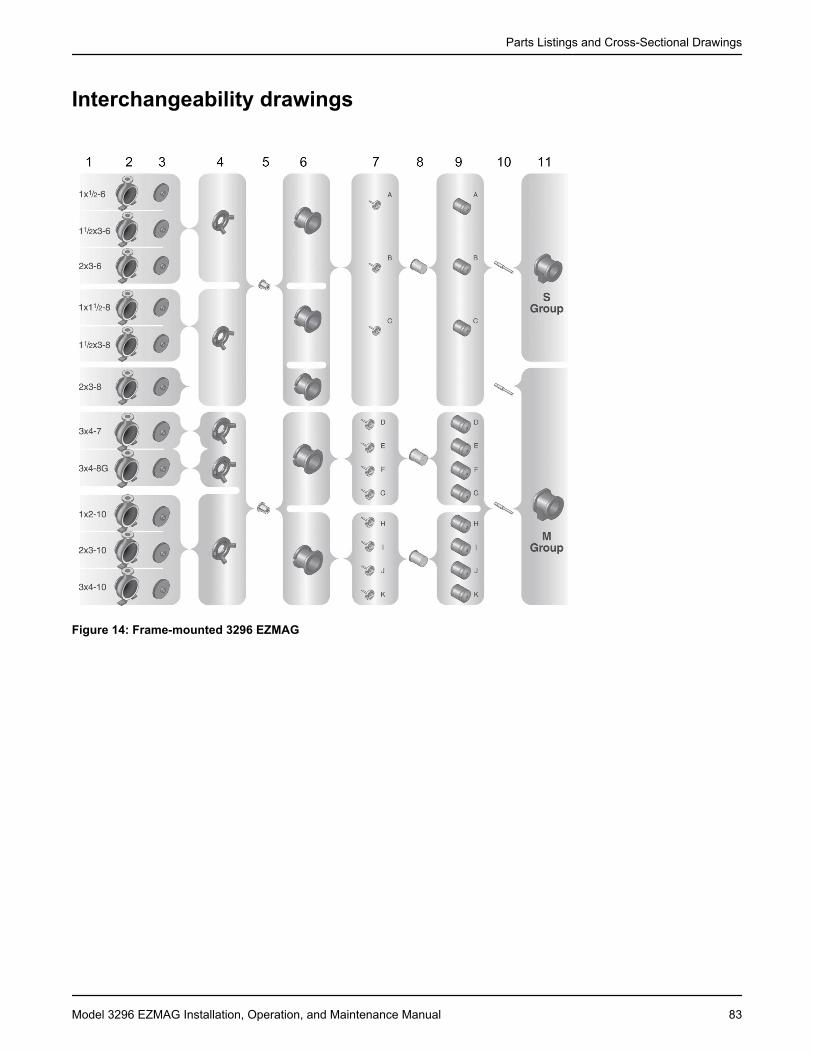
Interchangeability drawings
Figure 14: Frame-mounted 3296 EZMAG
Parts Listings and Cross-Sectional Drawings
Model 3296 EZMAG Installation, Operation, and Maintenance Manual 83

Figure 15: Close-coupled 3296 EZMAG
Interchangeability drawings parts list
1. Size 6. Frame adapter 11. Bearing frame2. Casing 7. Driven magnet 12. Stub shaft3. Impeller 8. Shell 13. Motor adapter4. Backplate 9. Drive magnet 14. Adapter plate5. Bearing cartridge 10. Drive shaft —
Parts Listings and Cross-Sectional Drawings
84 Model 3296 EZMAG Installation, Operation, and Maintenance Manual
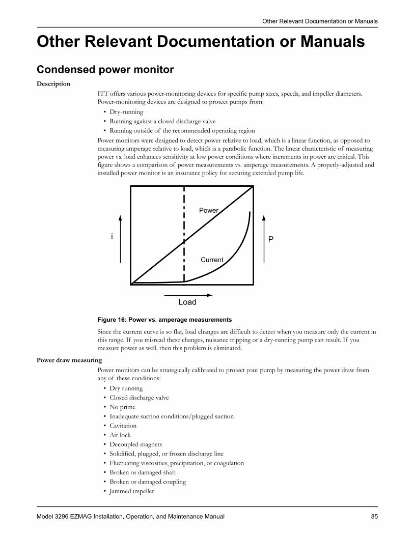
Other Relevant Documentation or ManualsCondensed power monitorDescription
ITT offers various power-monitoring devices for specific pump sizes, speeds, and impeller diameters.Power-monitoring devices are designed to protect pumps from:
• Dry-running• Running against a closed discharge valve• Running outside of the recommended operating region
Power monitors were designed to detect power relative to load, which is a linear function, as opposed tomeasuring amperage relative to load, which is a parabolic function. The linear characteristic of measuringpower vs. load enhances sensitivity at low power conditions where increments in power are critical. Thisfigure shows a comparison of power measurements vs. amperage measurements. A properly-adjusted andinstalled power monitor is an insurance policy for securing extended pump life.
i P
Power
Current
Load
Figure 16: Power vs. amperage measurements
Since the current curve is so flat, load changes are difficult to detect when you measure only the current inthis range. If you misread these changes, nuisance tripping or a dry-running pump can result. If youmeasure power as well, then this problem is eliminated.
Power draw measuringPower monitors can be strategically calibrated to protect your pump by measuring the power draw fromany of these conditions:
• Dry running• Closed discharge valve• No prime• Inadequate suction conditions/plugged suction• Cavitation• Air lock• Decoupled magnets• Solidified, plugged, or frozen discharge line• Fluctuating viscosities, precipitation, or coagulation• Broken or damaged shaft• Broken or damaged coupling• Jammed impeller
Other Relevant Documentation or Manuals
Model 3296 EZMAG Installation, Operation, and Maintenance Manual 85
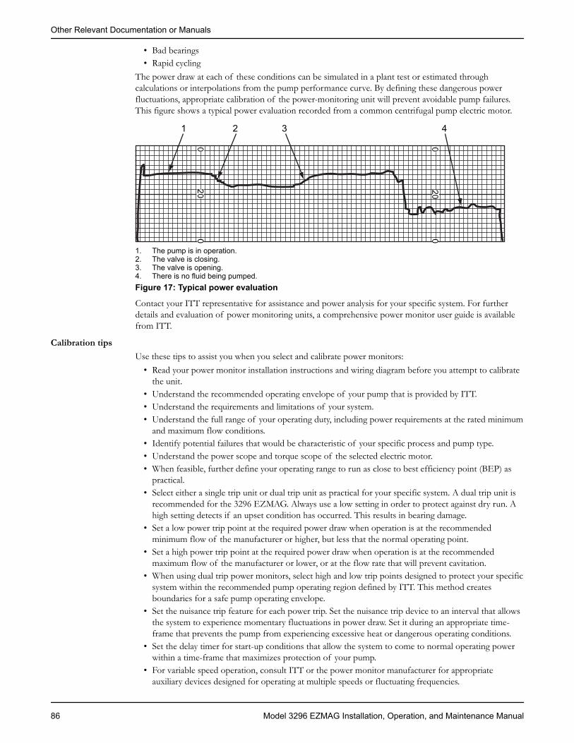
• Bad bearings• Rapid cycling
The power draw at each of these conditions can be simulated in a plant test or estimated throughcalculations or interpolations from the pump performance curve. By defining these dangerous powerfluctuations, appropriate calibration of the power-monitoring unit will prevent avoidable pump failures.This figure shows a typical power evaluation recorded from a common centrifugal pump electric motor.
20 20
0 0
0 01 2 3 4
1. The pump is in operation.2. The valve is closing.3. The valve is opening.4. There is no fluid being pumped.Figure 17: Typical power evaluation
Contact your ITT representative for assistance and power analysis for your specific system. For furtherdetails and evaluation of power monitoring units, a comprehensive power monitor user guide is availablefrom ITT.
Calibration tipsUse these tips to assist you when you select and calibrate power monitors:
• Read your power monitor installation instructions and wiring diagram before you attempt to calibratethe unit.
• Understand the recommended operating envelope of your pump that is provided by ITT.• Understand the requirements and limitations of your system.• Understand the full range of your operating duty, including power requirements at the rated minimum
and maximum flow conditions.• Identify potential failures that would be characteristic of your specific process and pump type.• Understand the power scope and torque scope of the selected electric motor.• When feasible, further define your operating range to run as close to best efficiency point (BEP) as
practical.• Select either a single trip unit or dual trip unit as practical for your specific system. A dual trip unit is
recommended for the 3296 EZMAG. Always use a low setting in order to protect against dry run. Ahigh setting detects if an upset condition has occurred. This results in bearing damage.
• Set a low power trip point at the required power draw when operation is at the recommendedminimum flow of the manufacturer or higher, but less that the normal operating point.
• Set a high power trip point at the required power draw when operation is at the recommendedmaximum flow of the manufacturer or lower, or at the flow rate that will prevent cavitation.
• When using dual trip power monitors, select high and low trip points designed to protect your specificsystem within the recommended pump operating region defined by ITT. This method createsboundaries for a safe pump operating envelope.
• Set the nuisance trip feature for each power trip. Set the nuisance trip device to an interval that allowsthe system to experience momentary fluctuations in power draw. Set it during an appropriate time-frame that prevents the pump from experiencing excessive heat or dangerous operating conditions.
• Set the delay timer for start-up conditions that allow the system to come to normal operating powerwithin a time-frame that maximizes protection of your pump.
• For variable speed operation, consult ITT or the power monitor manufacturer for appropriateauxiliary devices designed for operating at multiple speeds or fluctuating frequencies.
Other Relevant Documentation or Manuals
86 Model 3296 EZMAG Installation, Operation, and Maintenance Manual

• Select an electrical enclosure that is suitable for the operating environment, or install the unit in anappropriate electrical panel.
• Do not activate the manual override of the power monitor until a thorough examination of the sourceof the problem is defined and corrected.
• Investigate and select power monitor features that are most suitable for your particular applicationand plant safety.
Other Relevant Documentation or Manuals
Model 3296 EZMAG Installation, Operation, and Maintenance Manual 87

Local ITT ContactsRegional officesRegion Address Telephone FaxNorth America (Headquarters) ITT - Goulds Pumps
240 Fall StreetSeneca Falls, NY 13148USA
+1–315–568–2811 +1–315–568–2418
Asia Pacific ITT Industrial Process10 Jalan Kilang #06-01Singapore 159410
+65–627–63693 +65– 627–63685
Europe ITT - Goulds PumpsMillwey Rise Industrial EstateAxminster, Devon, EnglandEX13 5HU
+44–1297–630250 +44–1297–630256
Latin America ITT - Goulds PumpsCamino La Colina # 1448Condominio Industrial El RosalHuechuraba – Santiago8580000Chile
+562–544–7000 +562–544–7001
Middle East and Africa ITT - Goulds PumpsAchileos Kyrou 4Neo Psychiko 115 25 AthensGreece
+30–210–677–0770 +30–210–677–5642
Local ITT Contacts
88 Model 3296 EZMAG Installation, Operation, and Maintenance Manual


How did we measure up?
It is our sincere intention to exceed our customer’s expectations on every order. Tellus if we achieved our goal on your order. Please take our customer satisfactionsurvey online at:www.ittindustrialproducts.com/feedbacksurvey.htmlWe appreciate you taking the time to provide your feedback. Thank you for buyingITT pumps, parts, and controls.
Contact Us
Goulds Pumps has offices, warehouses and manufacturing facilities worldwide,while doing business in over 100 countries in the Americas, Europe, the Middle Eastand Asia Pacific. To find your nearest distributor, use our convenient Sales andService Locator found on our Web site.
Visit our Web site for the latest version of this document and more informationhttp://www.gouldspumps.com
ITT - Goulds Pumps240 Fall StreetSeneca Falls, NY 13148USATel. 1–800–446–8537Fax (315) 568–2418
© 2010 ITT Corporation. The original instruction is in English. All non-English instructions are translations of the originalinstruction. en-US.2010-07.IOM.3296EZMag