Embed Size (px)
Citation preview

GRAPHIC OPERATION TERMINAL
User's Manual (Hardware)
SeriesGOT2000

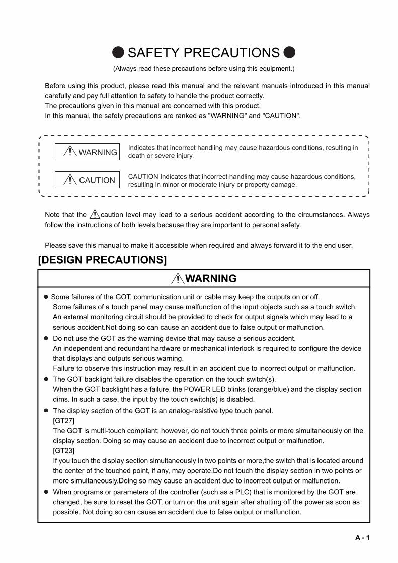
SAFETY PRECAUTIONS(Always read these precautions before using this equipment.)
Before using this product, please read this manual and the relevant manuals introduced in this manual
carefully and pay full attention to safety to handle the product correctly.
The precautions given in this manual are concerned with this product.
In this manual, the safety precautions are ranked as "WARNING" and "CAUTION".
Note that the caution level may lead to a serious accident according to the circumstances. Always
follow the instructions of both levels because they are important to personal safety.
Please save this manual to make it accessible when required and always forward it to the end user.
[DESIGN PRECAUTIONS]
WARNING
Some failures of the GOT, communication unit or cable may keep the outputs on or off.
Some failures of a touch panel may cause malfunction of the input objects such as a touch switch.
An external monitoring circuit should be provided to check for output signals which may lead to a
serious accident.Not doing so can cause an accident due to false output or malfunction.
Do not use the GOT as the warning device that may cause a serious accident.
An independent and redundant hardware or mechanical interlock is required to configure the device
that displays and outputs serious warning.
Failure to observe this instruction may result in an accident due to incorrect output or malfunction.
The GOT backlight failure disables the operation on the touch switch(s).
When the GOT backlight has a failure, the POWER LED blinks (orange/blue) and the display section
dims. In such a case, the input by the touch switch(s) is disabled.
The display section of the GOT is an analog-resistive type touch panel.
[GT27]
The GOT is multi-touch compliant; however, do not touch three points or more simultaneously on the
display section. Doing so may cause an accident due to incorrect output or malfunction.
[GT23]
If you touch the display section simultaneously in two points or more,the switch that is located around
the center of the touched point, if any, may operate.Do not touch the display section in two points or
more simultaneously.Doing so may cause an accident due to incorrect output or malfunction.
When programs or parameters of the controller (such as a PLC) that is monitored by the GOT are
changed, be sure to reset the GOT, or turn on the unit again after shutting off the power as soon as
possible. Not doing so can cause an accident due to false output or malfunction.
WARNING
CAUTION
Indicates that incorrect handling may cause hazardous conditions, resulting in death or severe injury.
CAUTION Indicates that incorrect handling may cause hazardous conditions, resulting in minor or moderate injury or property damage.
A - 1
[DESIGN PRECAUTIONS]
[MOUNTING PRECAUTIONS]
WARNING
If a communication fault (including cable disconnection) occurs during monitoring on the GOT,
communication between the GOT and PLC CPU is suspended and the GOT becomes inoperative.
For bus connection (GT27 Only) : The CPU becomes faulty and the GOT becomes inoperative.
For other than bus connection : The GOT becomes inoperative.
A system where the GOT is used should be configured to perform any significant operation to the
system by using the switches of a device other than the GOT on the assumption that a GOT
communication fault will occur.
Not doing so can cause an accident due to false output or malfunction.
CAUTION
Do not bundle the control and communication cables with main-circuit, power or other wiring.
Run the above cables separately from such wiring and keep them a minimum of 100mm apart.
Not doing so noise can cause a malfunction.
Do not press the GOT display section with a pointed material as a pen or driver.
Doing so can result in a damage or failure of the display section.
When the GOT is connected to the Ethernet network, the available IP address is restricted according
to the system configuration.• When multiple GOTs are connected to the Ethernet network :
Do not set the IP address (192.168.3.18) for the GOTs and the controllers in the network.• When a single GOT is connected to the Ethernet network :
Do not set the IP address (192.168.3.18) for the controllers except the GOT in the network.Doing so can cause the IP address duplication.
The duplication can negatively affect the communication of the device with the IP address
(192.168.3.18).
The operation at the IP address duplication depends on the devices and the system.
Turn on the controllers and the network devices to be ready for communication before they
communicate with the GOT.
Failure to do so can cause a communication error on the GOT.
When the GOT is subject to shock or vibration, or some colors appear on the screen of the GOT, the
screen of the GOT might flicker.
WARNING
Be sure to shut off all phases of the external power supply used by the system before mounting or
removing the GOT main unit to/from the panel.
Not doing so can cause the unit to fail or malfunction.
Be sure to shut off all phases of the external power supply used by the system before mounting or
removing the option unit onto/from the GOT. (GT27 Only)
A - 2

[MOUNTING PRECAUTIONS]
[WIRING PRECAUTIONS]
CAUTION
Use the GOT in the environment that satisfies the general specifications described in this manual.
Not doing so can cause an electric shock, fire, malfunction or product damage or deterioration.
When mounting the GOT to the control panel, tighten the mounting screws in the specified torque
range (0.36 N·m to 0.48 N·m) with a Phillips-head screwdriver No.2.
Undertightening can cause the GOT to drop, short circuit or malfunction.
Overtightening can cause a drop, short circuit or malfunction due to the damage of the screws or the
GOT.
When loading the communication unit or option unit other than wireless LAN unit to the GOT, fit it to
the connection interface of the GOT and tighten the mounting screws in the specified torque range
(0.36 N•m to 0.48 N•m) with a Phillips-head screwdriver No.2.
When loading the wireless LAN unit to the GOT, fit it to the side interface of GOT and tighten the
mounting screws in the specified torque range (0.10 N•m to 0.14 N•m) with a Phillips-head
screwdriver No.1.
Under tightening can cause the GOT to drop, short circuit or malfunction.
Overtightening can cause a drop, failure or malfunction due to the damage of the screws or unit.
(GT27 Only)
When closing the USB environmental protection cover, fix the cover to the GOT by pushing the
[PUSH] mark on the latch firmly to comply with the protective structure.(GT27 Only)
Remove the protective film of the GOT.
When the user continues using the GOT with the protective film, the film may not be removed.In
addition, for the models equipped with the human sensor function, using the GOT with the protective
film may cause the human sensor not to function properly
Operate and store the GOT in environments without direct sunlight, high temperature, dust, humidity,
and vibrations.
When using the GOT in the environment of oil or chemicals, use the protective cover for oil.Failure to
do so may cause failure or malfunction due to the oil or chemical entering into the GOT.
WARNING
Be sure to shut off all phases of the external power supply used by the system before wiring.
Failure to do so may result in an electric shock, product damage or malfunctions.
CAUTION
Make sure to ground the FG terminal and LG terminal of the GOT power supply section to the
protective ground conductors dedicated to the GOT with a ground resistance of 100 Ω or less.
When tightening the terminal screws, use a Phillips-head screwdriver No.2.
Terminal screws which are not to be used must be tightened always at torque 0.5 N·m to 0.8 N·m.
Otherwise there will be a danger of short circuit against the solderless terminals.
A - 3
[WIRING PRECAUTIONS]
[TEST OPERATION PRECAUTIONS]
CAUTION
Use applicable solderless terminals and tighten them with the specified torque.
If any solderless spade terminal is used, it may be disconnected when the terminal screw comes
loose, resulting in failure.
Correctly wire the GOT power supply section after confirming the rated voltage and terminal
arrangement of the product.
Not doing so can cause a fire or failure.
Tighten the terminal screws of the GOT power supply section in the specified torque range (0.5 N·m
to 0.8 N·m).
Undertightening can cause a short circuit or malfunction.
Overtightening can cause a short circuit or malfunction due to the damage of the screws or the GOT.
Exercise care to avoid foreign matter such as chips and wire offcuts entering the GOT.
Not doing so can cause a fire, failure or malfunction.
The module has an ingress prevention label on its top to prevent foreign matter, such as wire offcuts,
from entering the module during wiring.
Do not peel this label during wiring.Before starting system operation, be sure to peel this label
because of heat dissipation. (GT27 Only)
Plug the communication cable into the GOT interface or the connector of the connected unit, and
tighten the mounting screws and the terminal screws in the specified torque range.
Undertightening can cause a short circuit or malfunction.
Overtightening can cause a short circuit or malfunction due to the damage of the screws or unit.
Plug the QnA/ACPU/Motion controller(A series) bus connection cable by inserting it into the
connector of the connected unit until it "clicks".
After plugging, check that it has been inserted snugly.
Not doing so can cause a malfunction due to a contact fault.(GT27 Only)
WARNING
Before performing the test operations of the user creation monitor screen (such as turning ON or
OFF bit device, changing the word device current value, changing the settings or current values of
the timer or counter, and changing the buffer memory current value), read through the manual
carefully and make yourself familiar with the operation method.
During test operation, never change the data of the devices which are used to perform significant
operation for the system.
False output or malfunction can cause an accident.
A - 4
[STARTUP/MAINTENANCE PRECAUTIONS]
WARNING
When power is on, do not touch the terminals.
Doing so can cause an electric shock or malfunction.
Correctly connect the battery connector.
Do not charge, disassemble, heat, short-circuit, solder, or throw the battery into the fire.
Doing so will cause the battery to produce heat, explode, or ignite, resulting in injury and fire.
Before starting cleaning or terminal screw retightening, always switch off the power externally in all
phases.
Not switching the power off in all phases can cause a unit failure or malfunction.
Undertightening can cause a short circuit or malfunction.
Overtightening can cause a short circuit or malfunction due to the damage of the screws or unit.
CAUTION
Do not disassemble or modify the unit.
Doing so can cause a failure, malfunction, injury or fire.
Do not touch the conductive and electronic parts of the unit directly.
Doing so can cause a unit malfunction or failure.
The cables connected to the unit must be run in ducts or clamped.
Not doing so can cause the unit or cable to be damaged due to the dangling, motion or accidental
pulling of the cables or can cause a malfunction due to a cable connection fault.
When unplugging the cable connected to the unit, do not hold and pull from the cable portion.
Doing so can cause the unit or cable to be damaged or can cause a malfunction due to a cable
connection fault.
Do not drop the module or subject it to strong shock. A module damage may result.
Do not drop or give an impact to the battery mounted to the unit.
Doing so may damage the battery, causing the battery fluid to leak inside the battery.If the battery is
dropped or given an impact, dispose of it without using.
Before touching the unit, always touch grounded metals, etc. to discharge static electricity from
human body, etc.
Not doing so can cause the unit to fail or malfunction.
Use the battery manufactured by Mitsubishi Electric Corporation.
Use of other batteries may cause a risk of fire or explosion.
Dispose of used battery promptly.
Keep away from children.Do not disassemble and do not dispose of in fire.
Be sure to shut off all phases of the external power supply before replacing the battery or using the
dip switch of the terminating resistor.
Not doing so can cause the unit to fail or malfunction by static electricity.
A - 5
[TOUCH PANEL PRECAUTIONS]
[PRECAUTIONS WHEN THE DATA STORAGE IS IN USE]
CAUTION
For the analog-resistive film type touch panels, normally the adjustment is not required.
However, the difference between a touched position and the object position may occur as the period
of use elapses.
When any difference between a touched position and the object position occurs, execute the touch
panel calibration.
When any difference between a touched position and the object position occurs, other object may be
activated.
This may cause an unexpected operation due to incorrect output or malfunction.
WARNING
If the SD card mounted on drive A of the GOT is removed while the GOT is accessed, processing for
the GOT might be interrupted about for 20 seconds.
The GOT cannot be operated during this period.
The functions that run in the background including a screen updating, alarm, logging, scripts, and
others are also interrupted.
Since this interruption makes an impact to the system operation, it might cause failure.After checking
the light off of SD card access LED, remove the SD card.
CAUTION
If the data storage mounted on the GOT is removed while the GOT is accessed, the data storage
and files are damaged.
To remove the data storage from the GOT, check that the access to the data storage in SD card
access LED, the system signal, and others is not performed.
When inserting a SD card into the GOT, make sure to close the SD card cover.
Failure to do so causes the data not to be read or written.
When removing the SD card from the GOT, make sure to support the SD card by hand as it may pop
out.
Failure to do so may cause the SD card to drop from the GOT, resulting in a failure or break.
When inserting a USB device into a USB interface of the GOT, make sure to insert the device into
the interface firmly.
Failure to do so may cause the USB device to drop from the GOT, resulting in a failure or break.
Before removing the USB device from the GOT, follow the procedure for removal on the utility screen
of the GOT.
After the successful completion dialog is displayed, remove the USB device by hand carefully.
Failure to do so may cause the USB device to drop from the GOT, resulting in a failure or break.
A - 6
[DISPOSAL PRECAUTIONS]
[TRANSPORTATION PRECAUTIONS]
CAUTION
When disposing of this product, treat it as industrial waste.
When disposing of batteries, separate them from other wastes according to the local regulations.
(Refer to the GOT2000 Series User’s Manual (Hardware) for details of the battery directive in the EU
member states.)
CAUTION
When transporting lithium batteries, make sure to treat them based on the transport regulations.
(Refer to the GOT2000 Series User’s Manual (Hardware) for details of the regulated models.)
Make sure to transport the GOT main unit and/or relevant unit(s) in the manner they will not be
exposed to the impact exceeding the impact resistance described in the general specifications of this
manual, as they are precision devices.
Failure to do so may cause the unit to fail.
Check if the unit operates correctly after transportation.
When fumigants that contain halogen materials such as fluorine, chlorine, bromine, and iodine are
used for disinfecting and protecting wooden packaging from insects, they cause malfunction when
entering our products.
Please take necessary precautions to ensure that remaining materials from fumigant do not enter
our products, or treat packaging with methods other than fumigation (heat method).
Additionally, disinfect and protect wood from insects before packing products.
A - 7
SAFETY PRECAUTIONS .........................................................................................................................A - 1
INTRODUCTION ......................................................................................................................................A - 8
CONTENTS ..............................................................................................................................................A - 8
List of Manuals for GT Works3 ...............................................................................................................A - 11
Abbreviations and Generic Terms ..........................................................................................................A - 12
1. OVERVIEW
1.1 GOT ................................................................................................................................................. 1 - 2
1.2 Features........................................................................................................................................... 1 - 2
2. SYSTEM CONFIGURATION
2.1 Overall Configuration ....................................................................................................................... 2 - 2
2.2 How to Read the Model Name......................................................................................................... 2 - 2
2.2.1 GOT model name..................................................................................................................... 2 - 2
2.2.2 Option model name.................................................................................................................. 2 - 3
2.3 System Equipment........................................................................................................................... 2 - 4
2.3.1 GOT ......................................................................................................................................... 2 - 4
2.3.2 Extension unit........................................................................................................................... 2 - 5
2.3.3 Software ................................................................................................................................... 2 - 7
2.3.4 Option....................................................................................................................................... 2 - 8
2.3.5 Cable........................................................................................................................................ 2 - 9
2.3.6 Others .................................................................................................................................... 2 - 17
3. SPECIFICATIONS
3.1 General Specifications..................................................................................................................... 3 - 2
3.1.1 GT27 ........................................................................................................................................ 3 - 2
3.1.2 GT23 ........................................................................................................................................ 3 - 3
3.2 Performance Specifications ............................................................................................................. 3 - 4
3.2.1 GT2712-S................................................................................................................................. 3 - 4
3.2.2 GT2710-S, GT2710-V .............................................................................................................. 3 - 6
3.2.3 GT2708-S, GT2708-V .............................................................................................................. 3 - 8
3.2.4 GT2310-V............................................................................................................................... 3 - 10
3.2.5 GT2308-V............................................................................................................................... 3 - 12
3.3 Specifications of Power Supply Section ........................................................................................ 3 - 14
3.3.1 GT27 Input power supply 100 V AC to 240 V AC .................................................................. 3 - 14
3.3.2 GT27 Input power supply 24 V DC ........................................................................................ 3 - 14
3.3.3 GT23 Input power supply 100 V AC to 240 V AC .................................................................. 3 - 15
3.3.4 GT23 Input power supply 24 V DC ........................................................................................ 3 - 15
3.4 Battery Specifications .................................................................................................................... 3 - 16
INTRODUCTION
Thank you for choosing the Mitsubishi Graphic Operation Terminal.
Before using the equipment, please read this manual carefully to use the equipment to its optimum.
CONTENTS
A - 8
4. PART NAMES AND SETTINGS
4.1 GT27................................................................................................................................................ 4 - 2
4.2 GT23................................................................................................................................................ 4 - 5
5. EMC DIRECTIVE AND LOW VOLTAGE DIRECTIVE
5.1 Overview.......................................................................................................................................... 5 - 2
5.1.1 Conforming standards in the EMC Directive ............................................................................ 5 - 2
5.1.2 Conforming standards in the Low Voltage Directive ................................................................ 5 - 3
5.2 EMC Directive Requirements .......................................................................................................... 5 - 4
5.2.1 Installing the GOT on the control panel.................................................................................... 5 - 4
5.2.2 Installing a noise filter (power supply line filter)........................................................................ 5 - 5
5.2.3 System configuration................................................................................................................ 5 - 6
5.2.4 Connection of power cables and ground cables .................................................................... 5 - 11
5.2.5 Fabricating a connection cable .............................................................................................. 5 - 12
5.2.6 Grounding a cable.................................................................................................................. 5 - 18
5.3 Low Voltage Directive Requirements............................................................................................. 5 - 19
5.3.1 Power supply.......................................................................................................................... 5 - 19
5.3.2 Control panel.......................................................................................................................... 5 - 19
5.3.3 Grounding .............................................................................................................................. 5 - 20
5.3.4 External wiring........................................................................................................................ 5 - 20
6. INSTALLATION AND REMOVAL
6.1 Installation Precautions.................................................................................................................... 6 - 2
6.2 Panel Cut Dimensions ..................................................................................................................... 6 - 2
6.3 Installation Position.......................................................................................................................... 6 - 3
6.4 Control Panel Inside Temperature and GOT Installation Angle....................................................... 6 - 6
6.5 Installing and Removing the GOT.................................................................................................... 6 - 6
6.5.1 Installing the GOT .................................................................................................................... 6 - 6
6.5.2 Removing the GOT .................................................................................................................. 6 - 7
6.6 Installing and Removing the Extension Unit .................................................................................... 6 - 8
6.6.1 Installing multiple extension units............................................................................................. 6 - 8
6.6.2 Removing the extension unit.................................................................................................... 6 - 9
6.7 Installing and Removing the Battery .............................................................................................. 6 - 11
6.7.1 Installing the battery ............................................................................................................... 6 - 11
6.7.2 Removing the battery ............................................................................................................. 6 - 12
6.8 Installing and Removing the SD Card............................................................................................ 6 - 14
6.8.1 Installing the SD card............................................................................................................. 6 - 14
6.8.2 Removing the SD card ........................................................................................................... 6 - 15
6.9 Installing and Removing the USB Devices .................................................................................... 6 - 16
6.9.1 Removing the USB devices ................................................................................................... 6 - 16
6.9.2 Removing the USB devices ................................................................................................... 6 - 16
6.10 Installing and Removing the USB cable ........................................................................................ 6 - 17
6.10.1 Installing the USB cable ......................................................................................................... 6 - 17
6.10.2 Removing the USB cable ....................................................................................................... 6 - 18
7. WIRNG OF POWER SUPPLY SECTION
7.1 Wiring of External Power Supply ..................................................................................................... 7 - 2
A - 9
7.2 Power Supply Wiring to the GOT..................................................................................................... 7 - 3
7.3 Grounding ........................................................................................................................................ 7 - 4
7.3.1 Grounding the GOT.................................................................................................................. 7 - 4
7.3.2 Causes of wiring-related malfunction and countermeasure examples..................................... 7 - 5
7.4 Wiring Inside and Outside the Control Panel ................................................................................... 7 - 7
7.4.1 Control panel inside wiring ....................................................................................................... 7 - 7
7.4.2 Control panel outside wiring..................................................................................................... 7 - 7
7.5 Attaching a Surge Suppressor to Control Equipment ...................................................................... 7 - 8
7.6 Grounding the Extension Unit .......................................................................................................... 7 - 9
7.6.1 Wiring of the FG cable of a bus connection cable.................................................................... 7 - 9
8. OPERATING THE GOT
8.1 Outline Procedure to Start the GOT ................................................................................................ 8 - 2
8.2 Creating Project Data ...................................................................................................................... 8 - 5
9. MAINTENANCE AND INSPECTION
9.1 Daily Inspection ............................................................................................................................... 9 - 2
9.2 Periodic Inspection .......................................................................................................................... 9 - 2
9.3 Screen Cleaning Method ................................................................................................................. 9 - 4
9.4 Low-Voltage Battery Detection and Battery Replacement............................................................... 9 - 5
10. TROUBLESHOOTING
10.1 GOT Restoration Sheets ............................................................................................................... 10 - 2
10.1.1 GOT status check sheet......................................................................................................... 10 - 3
10.1.2 GOT installation status check sheet....................................................................................... 10 - 8
10.1.3 System configuration check sheet ....................................................................................... 10 - 13
10.2 Troubleshooting for the Bus Connection ..................................................................................... 10 - 14
10.2.1 Identifying the error position................................................................................................. 10 - 14
10.2.2 Narrowing the possible error positions................................................................................. 10 - 15
10.2.3 Specific example of troubleshooting .................................................................................... 10 - 16
10.3 Error Messages and System Alarms ........................................................................................... 10 - 17
10.3.1 Displayed contents............................................................................................................... 10 - 17
10.3.2 Error messages and system alarms..................................................................................... 10 - 18
11. APPENDICES
11.1 External Dimension Diagrams ....................................................................................................... 11 - 2
11.2 Confirming of Versions and Conforming Standards .................................................................... 11 - 15
11.3 Transportation Precautions.......................................................................................................... 11 - 15
11.3.1 Relevant models .................................................................................................................. 11 - 15
11.3.2 Transportation guidelines..................................................................................................... 11 - 15
REVISIONS
WARRANTY
A - 10
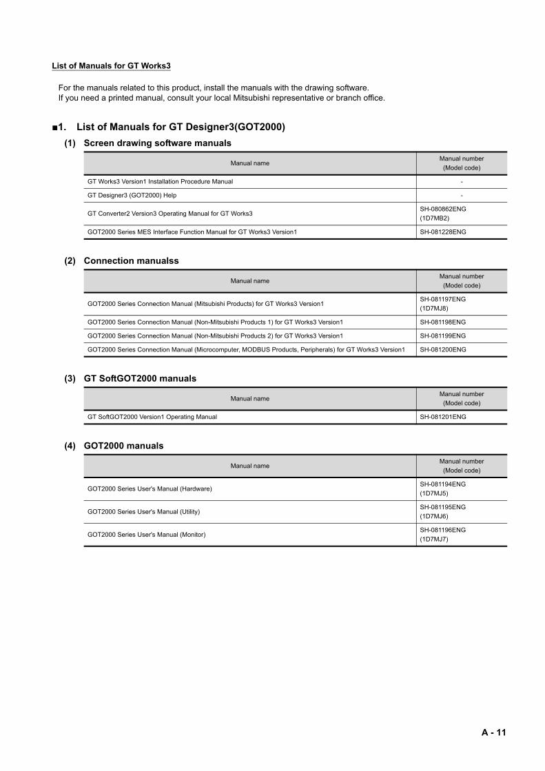
List of Manuals for GT Works3
For the manuals related to this product, install the manuals with the drawing software.If you need a printed manual, consult your local Mitsubishi representative or branch office.
1. List of Manuals for GT Designer3(GOT2000)
(1) Screen drawing software manuals
(2) Connection manualss
(3) GT SoftGOT2000 manuals
(4) GOT2000 manuals
Manual nameManual number
(Model code)
GT Works3 Version1 Installation Procedure Manual -
GT Designer3 (GOT2000) Help -
GT Converter2 Version3 Operating Manual for GT Works3SH-080862ENG
(1D7MB2)
GOT2000 Series MES Interface Function Manual for GT Works3 Version1 SH-081228ENG
Manual nameManual number
(Model code)
GOT2000 Series Connection Manual (Mitsubishi Products) for GT Works3 Version1SH-081197ENG
(1D7MJ8)
GOT2000 Series Connection Manual (Non-Mitsubishi Products 1) for GT Works3 Version1 SH-081198ENG
GOT2000 Series Connection Manual (Non-Mitsubishi Products 2) for GT Works3 Version1 SH-081199ENG
GOT2000 Series Connection Manual (Microcomputer, MODBUS Products, Peripherals) for GT Works3 Version1 SH-081200ENG
Manual nameManual number
(Model code)
GT SoftGOT2000 Version1 Operating Manual SH-081201ENG
Manual nameManual number
(Model code)
GOT2000 Series User's Manual (Hardware)SH-081194ENG
(1D7MJ5)
GOT2000 Series User's Manual (Utility)SH-081195ENG
(1D7MJ6)
GOT2000 Series User's Manual (Monitor)SH-081196ENG
(1D7MJ7)
A - 11
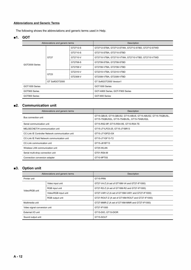
Abbreviations and Generic Terms
The following shows the abbreviations and generic terms used in Help.
1. GOT
2. Communication unit
3. Option unit
Abbreviations and generic terms Description
GOT2000 Series
GT27
GT2712-S GT2712-STBA, GT2712-STWA, GT2712-STBD, GT2712-STWD
GT2710-S GT2710-STBA, GT2710-STBD
GT2710-V GT2710-VTBA, GT2710-VTWA, GT2710-VTBD, GT2710-VTWD
GT2708-S GT2708-STBA, GT2708-STBD
GT2708-V GT2708-VTBA, GT2708-VTBD
GT23GT2310-V GT2310-VTBA, GT2310-VTBD
GT2308-V GT2308-VTBA, GT2308-VTBD
GT SoftGOT2000 GT SoftGOT2000 Version1
GOT1000 Series GOT1000 Series
GOT900 Series GOT-A900 Series, GOT-F900 Series
GOT800 Series GOT-800 Series
Abbreviations and generic terms Description
Bus connection unitGT15-QBUS, GT15-QBUS2, GT15-ABUS, GT15-ABUS2, GT15-75QBUSL,
GT15-75QBUS2L, GT15-75ABUSL, GT15-75ABUS2L
Serial communication unit GT15-RS2-9P, GT15-RS4-9S, GT15-RS4-TE
MELSECNET/H communication unit GT15-J71LP23-25, GT15-J71BR13
CC-Link IE Controller Network communication unit GT15-J71GP23-SX
CC-Link IE Field Network communication unit GT15-J71GF13-T2
CC-Link communication unit GT15-J61BT13
Wireless LAN communication unit GT25-WLAN
Serial multi-drop connection unit GT01-RS4-M
Connection conversion adapter GT10-9PT5S
Abbreviations and generic terms Description
Printer unit GT15-PRN
Video/RGB unit
Video input unit GT27-V4-Z (A set of GT16M-V4 and GT27-IF1000)
RGB input unit GT27-R2-Z (A set of GT16M-R2 and GT27-IF1000)
Video/RGB input unit GT27-V4R1-Z (A set of GT16M-V4R1 and GT27-IF1000)
RGB output unit GT27-ROUT-Z (A set of GT16M-ROUT and GT27-IF1000)
Multimedia unit GT27-MMR-Z (A set of GT16M-MMR and GT27-IF1000)
Video signal conversion unit GT27-IF1000
External I/O unit GT15-DIO, GT15-DIOR
Sound output unit GT15-SOUT
A - 12
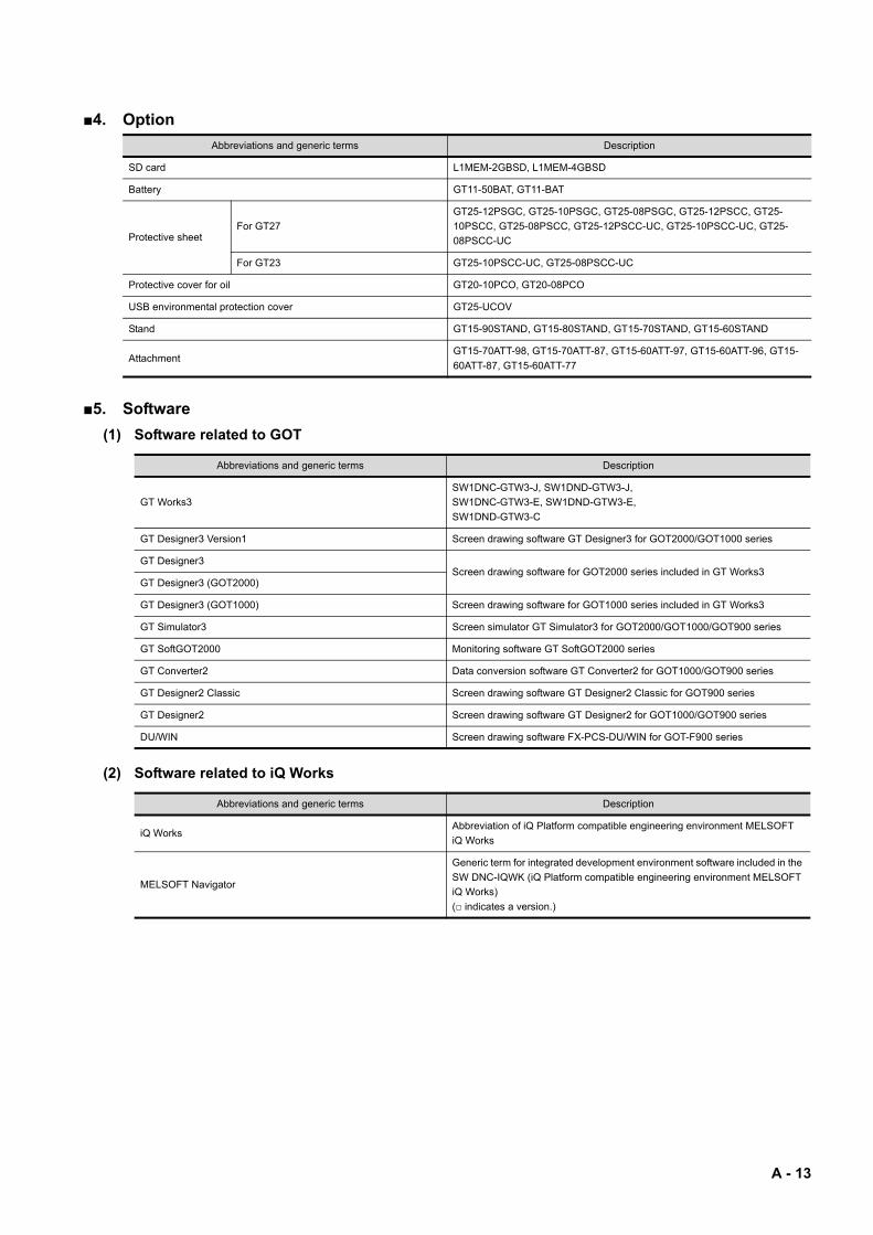
4. Option
5. Software
(1) Software related to GOT
(2) Software related to iQ Works
Abbreviations and generic terms Description
SD card L1MEM-2GBSD, L1MEM-4GBSD
Battery GT11-50BAT, GT11-BAT
Protective sheetFor GT27
GT25-12PSGC, GT25-10PSGC, GT25-08PSGC, GT25-12PSCC, GT25-
10PSCC, GT25-08PSCC, GT25-12PSCC-UC, GT25-10PSCC-UC, GT25-
08PSCC-UC
For GT23 GT25-10PSCC-UC, GT25-08PSCC-UC
Protective cover for oil GT20-10PCO, GT20-08PCO
USB environmental protection cover GT25-UCOV
Stand GT15-90STAND, GT15-80STAND, GT15-70STAND, GT15-60STAND
AttachmentGT15-70ATT-98, GT15-70ATT-87, GT15-60ATT-97, GT15-60ATT-96, GT15-
60ATT-87, GT15-60ATT-77
Abbreviations and generic terms Description
GT Works3
SW1DNC-GTW3-J, SW1DND-GTW3-J,
SW1DNC-GTW3-E, SW1DND-GTW3-E,
SW1DND-GTW3-C
GT Designer3 Version1 Screen drawing software GT Designer3 for GOT2000/GOT1000 series
GT Designer3Screen drawing software for GOT2000 series included in GT Works3
GT Designer3 (GOT2000)
GT Designer3 (GOT1000) Screen drawing software for GOT1000 series included in GT Works3
GT Simulator3 Screen simulator GT Simulator3 for GOT2000/GOT1000/GOT900 series
GT SoftGOT2000 Monitoring software GT SoftGOT2000 series
GT Converter2 Data conversion software GT Converter2 for GOT1000/GOT900 series
GT Designer2 Classic Screen drawing software GT Designer2 Classic for GOT900 series
GT Designer2 Screen drawing software GT Designer2 for GOT1000/GOT900 series
DU/WIN Screen drawing software FX-PCS-DU/WIN for GOT-F900 series
Abbreviations and generic terms Description
iQ WorksAbbreviation of iQ Platform compatible engineering environment MELSOFT
iQ Works
MELSOFT Navigator
Generic term for integrated development environment software included in the
SW DNC-IQWK (iQ Platform compatible engineering environment MELSOFT
iQ Works)
( indicates a version.)
A - 13
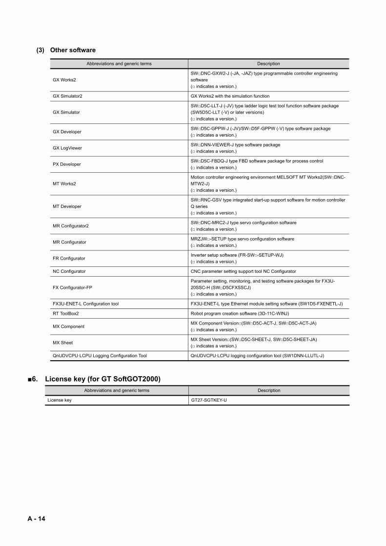
(3) Other software
6. License key (for GT SoftGOT2000)
Abbreviations and generic terms Description
GX Works2
SWDNC-GXW2-J (-JA, -JAZ) type programmable controller engineering
software
( indicates a version.)
GX Simulator2 GX Works2 with the simulation function
GX Simulator
SWD5C-LLT-J (-JV) type ladder logic test tool function software package
(SW5D5C-LLT (-V) or later versions)
( indicates a version.)
GX DeveloperSWD5C-GPPW-J (-JV)/SWD5F-GPPW (-V) type software package
( indicates a version.)
GX LogViewerSWDNN-VIEWER-J type software package
( indicates a version.)
PX DeveloperSWD5C-FBDQ-J type FBD software package for process control
( indicates a version.)
MT Works2
Motion controller engineering environment MELSOFT MT Works2(SWDNC-
MTW2-J)
( indicates a version.)
MT Developer
SWRNC-GSV type integrated start-up support software for motion controller
Q series
( indicates a version.)
MR Configurator2SWDNC-MRC2-J type servo configuration software
( indicates a version.)
MR ConfiguratorMRZJW-SETUP type servo configuration software
( indicates a version.)
FR ConfiguratorInverter setup software (FR-SW-SETUP-WJ)
( indicates a version.)
NC Configurator CNC parameter setting support tool NC Configurator
FX Configurator-FP
Parameter setting, monitoring, and testing software packages for FX3U-
20SSC-H (SWD5CFXSSCJ)
( indicates a version.)
FX3U-ENET-L Configuration tool FX3U-ENET-L type Ethernet module setting software (SW1D5-FXENETL-J)
RT ToolBox2 Robot program creation software (3D-11C-WINJ)
MX ComponentMX Component Version(SWD5C-ACT-J, SWD5C-ACT-JA)
( indicates a version.)
MX SheetMX Sheet Version(SWD5C-SHEET-J, SWD5C-SHEET-JA)
( indicates a version.)
QnUDVCPU·LCPU Logging Configuration Tool QnUDVCPU·LCPU logging configuration tool (SW1DNN-LLUTL-J)
Abbreviations and generic terms Description
License key GT27-SGTKEY-U
A - 14
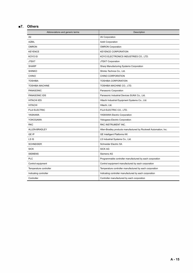
7. Others
Abbreviations and generic terms Description
IAI IAI Corporation
AZBIL Azbil Corporation
OMRON OMRON Corporation
KEYENCE KEYENCE CORPORATION
KOYO EI KOYO ELECTRONICS INDUSTRIES CO., LTD.
JTEKT JTEKT Corporation
SHARP Sharp Manufacturing Systems Corporation
SHINKO Shinko Technos Co., Ltd.
CHINO CHINO CORPORATION
TOSHIBA TOSHIBA CORPORATION
TOSHIBA MACHINE TOSHIBA MACHINE CO., LTD.
PANASONIC Panasonic Corporation
PANASONIC IDS Panasonic Industrial Devices SUNX Co., Ltd.
HITACHI IES Hitachi Industrial Equipment Systems Co., Ltd.
HITACHI Hitachi, Ltd.
FUJI ELECTRIC FUJI ELECTRIC CO., LTD.
YASKAWA YASKAWA Electric Corporation
YOKOGAWA Yokogawa Electric Corporation
RKC RKC INSTRUMENT INC.
ALLEN-BRADLEY Allen-Bradley products manufactured by Rockwell Automation, Inc.
GE IP GE Intelligent Platforms KK
LS IS LS Industrial Systems Co., Ltd.
SCHNEIDER Schneider Electric SA
SICK SICK AG
SIEMENS Siemens AG
PLC Programmable controller manufactured by each corporation
Control equipment Control equipment manufactured by each corporation
Temperature controller Temperature controller manufactured by each corporation
Indicating controller Indicating controller manufactured by each corporation
Controller Controller manufactured by each corporation
A - 15

A - 16
1
OV
ER
VIE
W
1. OVERVIEW
1.1 GOT . . . . . . . . . . . . . . . . . . . . . . . . . . . . . . . . . . . . . . . . . . . . . . . . 1 - 2
1.2 Features. . . . . . . . . . . . . . . . . . . . . . . . . . . . . . . . . . . . . . . . . . . . 1 - 2
1 - 1
1.1 GOT
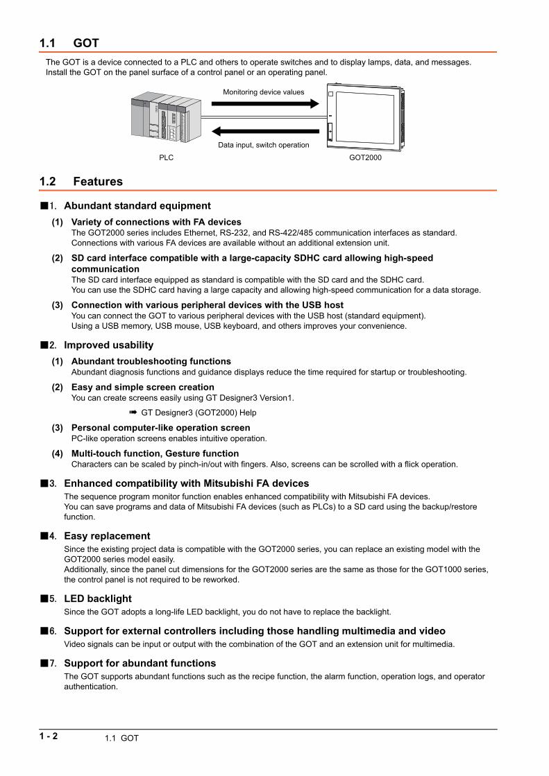
The GOT is a device connected to a PLC and others to operate switches and to display lamps, data, and messages.Install the GOT on the panel surface of a control panel or an operating panel.
1.2 Features
1. Abundant standard equipment
(1) Variety of connections with FA devicesThe GOT2000 series includes Ethernet, RS-232, and RS-422/485 communication interfaces as standard.Connections with various FA devices are available without an additional extension unit.
(2) SD card interface compatible with a large-capacity SDHC card allowing high-speed communicationThe SD card interface equipped as standard is compatible with the SD card and the SDHC card.You can use the SDHC card having a large capacity and allowing high-speed communication for a data storage.
(3) Connection with various peripheral devices with the USB hostYou can connect the GOT to various peripheral devices with the USB host (standard equipment).Using a USB memory, USB mouse, USB keyboard, and others improves your convenience.
2. Improved usability
(1) Abundant troubleshooting functionsAbundant diagnosis functions and guidance displays reduce the time required for startup or troubleshooting.
(2) Easy and simple screen creationYou can create screens easily using GT Designer3 Version1.
GT Designer3 (GOT2000) Help
(3) Personal computer-like operation screenPC-like operation screens enables intuitive operation.
(4) Multi-touch function, Gesture functionCharacters can be scaled by pinch-in/out with fingers. Also, screens can be scrolled with a flick operation.
3. Enhanced compatibility with Mitsubishi FA devicesThe sequence program monitor function enables enhanced compatibility with Mitsubishi FA devices.You can save programs and data of Mitsubishi FA devices (such as PLCs) to a SD card using the backup/restore function.
4. Easy replacementSince the existing project data is compatible with the GOT2000 series, you can replace an existing model with the GOT2000 series model easily.Additionally, since the panel cut dimensions for the GOT2000 series are the same as those for the GOT1000 series, the control panel is not required to be reworked.
5. LED backlightSince the GOT adopts a long-life LED backlight, you do not have to replace the backlight.
6. Support for external controllers including those handling multimedia and videoVideo signals can be input or output with the combination of the GOT and an extension unit for multimedia.
7. Support for abundant functionsThe GOT supports abundant functions such as the recipe function, the alarm function, operation logs, and operator authentication.
GOT2000PLC
Monitoring device values
Data input, switch operation
1 - 2 1.1 GOT
2
SY
ST
EM
CO
NF
IGU
RA
TIO
N
2. SYSTEM CONFIGURATION
2.1 Overall Configuration . . . . . . . . . . . . . . . . . . . . . . . . . . . . . . . . . 2 - 2
2.2 How to Read the Model Name . . . . . . . . . . . . . . . . . . . . . . . . . . 2 - 2
2.3 System Equipment . . . . . . . . . . . . . . . . . . . . . . . . . . . . . . . . . . . 2 - 4
2 - 1
2.1 Overall Configuration
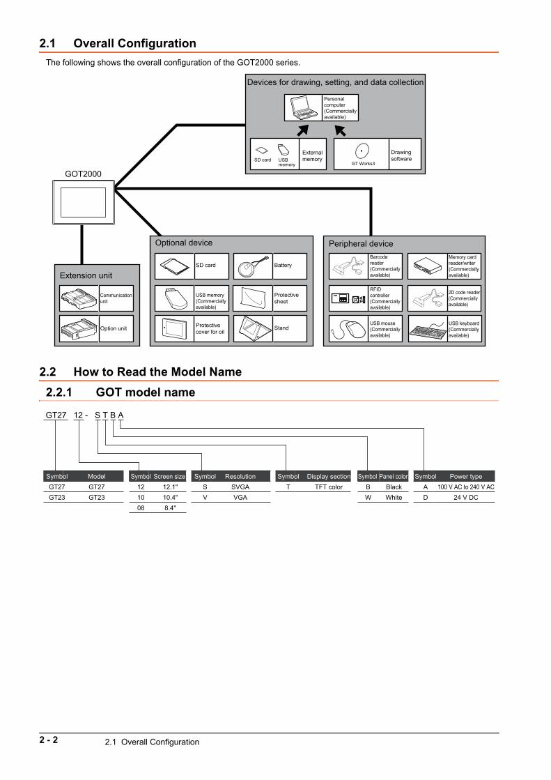
The following shows the overall configuration of the GOT2000 series.
2.2 How to Read the Model Name
2.2.1 GOT model name
Personal computer (Commercially available)
External memoryUSB
memorySD card
Drawing software
GT Works3
Devices for drawing, setting, and data collection
RFID controller (Commercially available)
USB mouse (Commercially available)
USB keyboard (Commercially available)
Peripheral device
Protective cover for oil
Protective sheet
Stand
SD card
USB memory (Commercially available)
Optional device
GOT2000
Communication unit
Option unit
Extension unitBattery
Memory card reader/writer (Commercially available)
Barcode reader (Commercially available)
2D code reader (Commercially available)
GT27 12 - S T B A
GT27GT23
ModelGT27GT23
Symbol12.1"10.4"8.4"
Screen size 121008
SymbolSVGAVGA
ResolutionSV
Symbol100 V AC to 240 V AC
24 V DC
Power typeAD
SymbolBlackWhite
Panel colorBW
SymbolTFT color
Display sectionT
Symbol
2 - 2 2.1 Overall Configuration
2
SY
ST
EM
CO
NF
IGU
RA
TIO
N
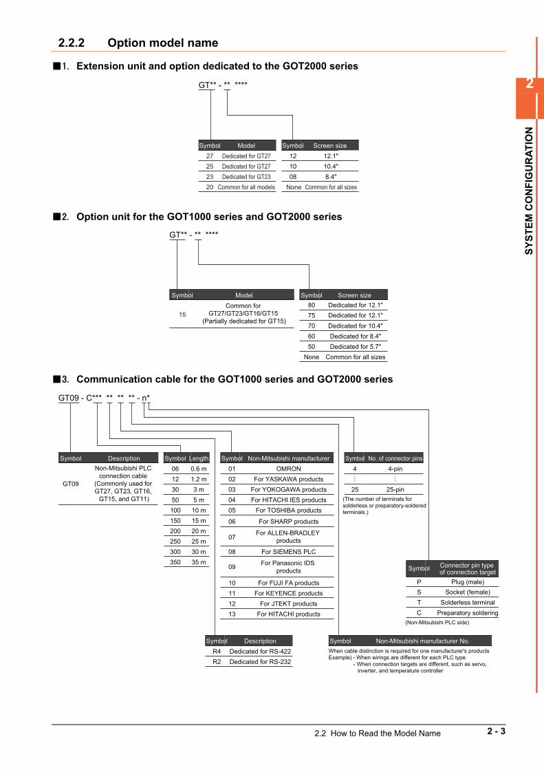
2.2.2 Option model name
1. Extension unit and option dedicated to the GOT2000 series
2. Option unit for the GOT1000 series and GOT2000 series
3. Communication cable for the GOT1000 series and GOT2000 series
GT** - ** ****
Dedicated for GT27Dedicated for GT27
Model
Dedicated for GT23Common for all models
2725
Symbol
2320
12.1"10.4"8.4"
Screen size 121008
Symbol
Common for all sizes None
GT** - ** ****
Common for GT27/GT23/GT16/GT15
(Partially dedicated for GT15)
Model
15
SymbolDedicated for 12.1"
Screen size 8075
Symbol
Dedicated for 10.4"70Dedicated for 8.4"60Dedicated for 5.7"50
Common for all sizesNone
Dedicated for 12.1"
GT09 - C*** ** ** ** - n*
Non-Mitsubishi PLC connection cable
(Commonly used for GT27, GT23, GT16,
GT15, and GT11)
Description
GT09
Symbol0.6 m1.2 m3 m
Length061230
Symbol
5 m10 m
50100
15 m20 m25 m
150200250
30 m35 m
300350
OMRONFor YASKAWA products
For YOKOGAWA products
Non-Mitsubishi manufacturer010203
Symbol
For HITACHI IES productsFor TOSHIBA products
0405
For SHARP products
For ALLEN-BRADLEY products
For SIEMENS PLC
06
07
08
For Panasonic IDS products
For FUJI FA products
09
10For KEYENCE products11
For JTEKT productsFor HITACHI products
1213
When cable distinction is required for one manufacturer's productsExample) When wirings are different for each PLC type When connection targets are different, such as servo, inverter, and temperature controller
Non-Mitsubishi manufacturer No.Symbol
4-pin
25-pin
No. of connector pins4
25
Symbol
(The number of terminals for solderless or preparatory-soldered terminals.)
… …
R4R2
Dedicated for RS-422Dedicated for RS-232
DescriptionSymbol
Connector pin type of connection targetSymbol
Plug (male)Socket (female)
Solderless terminal
PST
Preparatory solderingC(Non-Mitsubishi PLC side)
2.2 How to Read the Model Name 2 - 3
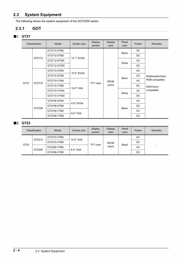
2.3 System Equipment
The following shows the system equipment of the GOT2000 series.
2.3.1 GOT
1. GT27
2. GT23
Classification Model Screen sizeDisplay section
Display color
Panel color
Power Remarks
GT27
GT2712
GT2712-STBA
12.1" SVGA
TFT color65536 colors
BlackAC
Multimedia/Video/RGB compatible
Multi-touch compatible
GT2712-STBD DC
GT2712-STWAWhite
AC
GT2712-STWD DC
GT2710
GT2710-STBA10.4" SVGA
Black
AC
GT2710-STBD DC
GT2710-VTBA
10.4" VGA
AC
GT2710-VTBD DC
GT2710-VTWAWhite
AC
GT2710-VTWD DC
GT2708
GT2708-STBA8.4" SVGA
Black
AC
GT2708-STBD DC
GT2708-VTBA8.4" VGA
AC
GT2708-VTBD DC
Classification Model Screen sizeDisplay section
Display color
Panel color
Power Remarks
GT23
GT2310GT2310-VTBA
10.4" VGA
TFT color65536 colors
Black
AC
-GT2310-VTBD DC
GT2308GT2308-VTBA
8.4" VGAAC
GT2308-VTBD DC
2 - 4 2.3 System Equipment
2
SY
ST
EM
CO
NF
IGU
RA
TIO
N
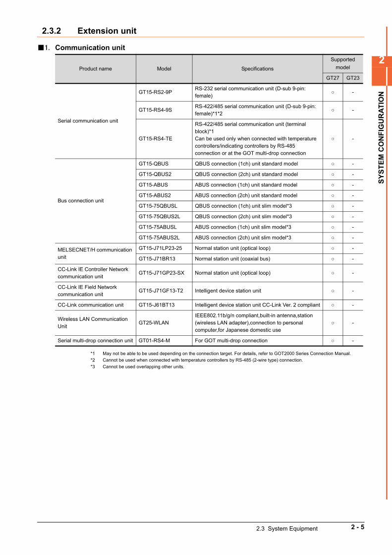
2.3.2 Extension unit
1. Communication unit
*1 May not be able to be used depending on the connection target. For details, refer to GOT2000 Series Connection Manual.
*2 Cannot be used when connected with temperature controllers by RS-485 (2-wire type) connection.
*3 Cannot be used overlapping other units.
Product name Model Specifications
Supported
model
GT27 GT23
Serial communication unit
GT15-RS2-9PRS-232 serial communication unit (D-sub 9-pin: female)
-
GT15-RS4-9SRS-422/485 serial communication unit (D-sub 9-pin: female)*1*2
-
GT15-RS4-TE
RS-422/485 serial communication unit (terminal block)*1Can be used only when connected with temperature controllers/indicating controllers by RS-485 connection or at the GOT multi-drop connection
-
Bus connection unit
GT15-QBUS QBUS connection (1ch) unit standard model -
GT15-QBUS2 QBUS connection (2ch) unit standard model -
GT15-ABUS ABUS connection (1ch) unit standard model -
GT15-ABUS2 ABUS connection (2ch) unit standard model -
GT15-75QBUSL QBUS connection (1ch) unit slim model*3 -
GT15-75QBUS2L QBUS connection (2ch) unit slim model*3 -
GT15-75ABUSL ABUS connection (1ch) unit slim model*3 -
GT15-75ABUS2L ABUS connection (2ch) unit slim model*3 -
MELSECNET/H communication unit
GT15-J71LP23-25 Normal station unit (optical loop) -
GT15-J71BR13 Normal station unit (coaxial bus) -
CC-Link IE Controller Network communication unit
GT15-J71GP23-SX Normal station unit (optical loop) -
CC-Link IE Field Network communication unit
GT15-J71GF13-T2 Intelligent device station unit -
CC-Link communication unit GT15-J61BT13 Intelligent device station unit CC-Link Ver. 2 compliant -
Wireless LAN Communication Unit
GT25-WLANIEEE802.11b/g/n compliant,built-in antenna,station (wireless LAN adapter),connection to personal computer,for Japanese domestic use
-
Serial multi-drop connection unit GT01-RS4-M For GOT multi-drop connection -
2.3 System Equipment 2 - 5
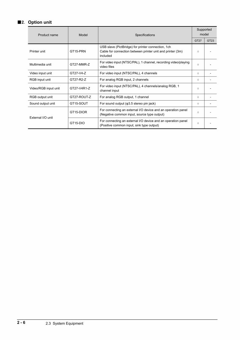
2. Option unit
Product name Model Specifications
Supported
model
GT27 GT23
Printer unit GT15-PRNUSB slave (PictBridge) for printer connection, 1chCable for connection between printer unit and printer (3m) included
-
Multimedia unit GT27-MMR-ZFor video input (NTSC/PAL), 1 channel, recording video/playing video files
-
Video input unit GT27-V4-Z For video input (NTSC/PAL), 4 channels -
RGB input unit GT27-R2-Z For analog RGB input, 2 channels -
Video/RGB input unit GT27-V4R1-ZFor video input (NTSC/PAL), 4 channels/analog RGB, 1 channel input
-
RGB output unit GT27-ROUT-Z For analog RGB output, 1 channel -
Sound output unit GT15-SOUT For sound output (φ3.5 stereo pin jack) -
External I/O unit
GT15-DIORFor connecting an external I/O device and an operation panel(Negative common input, source type output)
-
GT15-DIOFor connecting an external I/O device and an operation panel(Positive common input, sink type output)
-
2 - 6 2.3 System Equipment
2
SY
ST
EM
CO
NF
IGU
RA
TIO
N
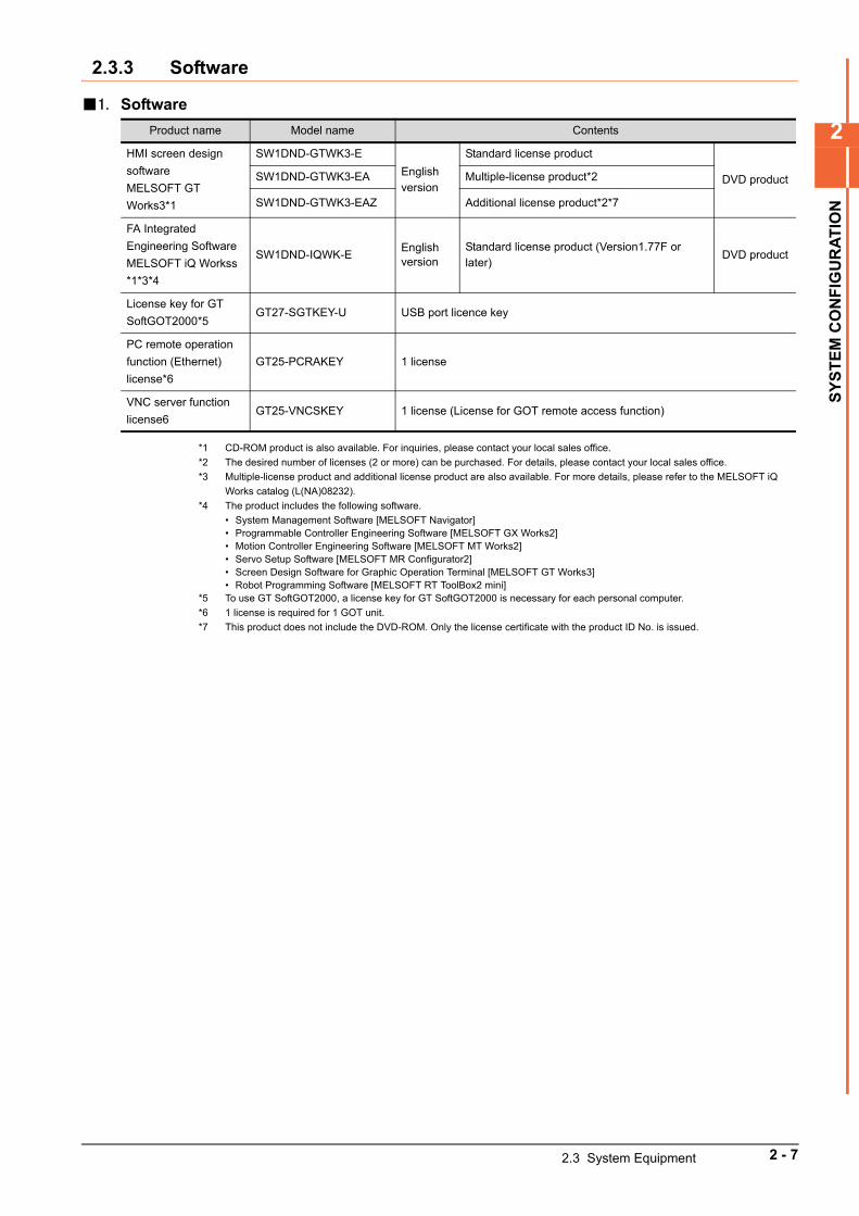
2.3.3 Software
1. Software
*1 CD-ROM product is also available. For inquiries, please contact your local sales office.
*2 The desired number of licenses (2 or more) can be purchased. For details, please contact your local sales office.
*3 Multiple-license product and additional license product are also available. For more details, please refer to the MELSOFT iQ
Works catalog (L(NA)08232).
*4 The product includes the following software.
• System Management Software [MELSOFT Navigator]• Programmable Controller Engineering Software [MELSOFT GX Works2] • Motion Controller Engineering Software [MELSOFT MT Works2]• Servo Setup Software [MELSOFT MR Configurator2]• Screen Design Software for Graphic Operation Terminal [MELSOFT GT Works3]• Robot Programming Software [MELSOFT RT ToolBox2 mini]
*5 To use GT SoftGOT2000, a license key for GT SoftGOT2000 is necessary for each personal computer.
*6 1 license is required for 1 GOT unit.
*7 This product does not include the DVD-ROM. Only the license certificate with the product ID No. is issued.
Product name Model name Contents
HMI screen design
software
MELSOFT GT
Works3*1
SW1DND-GTWK3-E
English version
Standard license product
DVD productSW1DND-GTWK3-EA Multiple-license product*2
SW1DND-GTWK3-EAZ Additional license product*2*7
FA Integrated
Engineering Software
MELSOFT iQ Workss
*1*3*4
SW1DND-IQWK-EEnglish version
Standard license product (Version1.77F or later)
DVD product
License key for GT
SoftGOT2000*5GT27-SGTKEY-U USB port licence key
PC remote operation
function (Ethernet)
license*6
GT25-PCRAKEY 1 license
VNC server function
license6GT25-VNCSKEY 1 license (License for GOT remote access function)
2.3 System Equipment 2 - 7
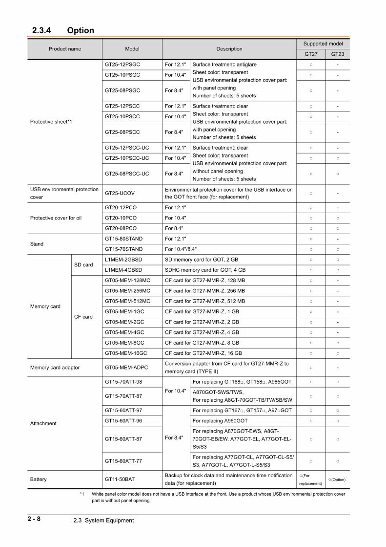
2.3.4 Option
*1 White panel color model does not have a USB interface at the front. Use a product whose USB environmental protection cover
part is without panel opening.
Product name Model DescriptionSupported model
GT27 GT23
Protective sheet*1
GT25-12PSGC For 12.1" Surface treatment: antiglare
Sheet color: transparent
USB environmental protection cover part:
with panel opening
Number of sheets: 5 sheets
-
GT25-10PSGC For 10.4" -
GT25-08PSGC For 8.4" -
GT25-12PSCC For 12.1" Surface treatment: clear
Sheet color: transparent
USB environmental protection cover part:
with panel opening
Number of sheets: 5 sheets
-
GT25-10PSCC For 10.4" -
GT25-08PSCC For 8.4" -
GT25-12PSCC-UC For 12.1" Surface treatment: clear
Sheet color: transparent
USB environmental protection cover part:
without panel opening
Number of sheets: 5 sheets
-
GT25-10PSCC-UC For 10.4"
GT25-08PSCC-UC For 8.4"
USB environmental protection
coverGT25-UCOV
Environmental protection cover for the USB interface on the GOT front face (for replacement)
-
Protective cover for oil
GT20-12PCO For 12.1" -
GT20-10PCO For 10.4"
GT20-08PCO For 8.4"
StandGT15-80STAND For 12.1" -
GT15-70STAND For 10.4"/8.4"
Memory card
SD cardL1MEM-2GBSD SD memory card for GOT, 2 GB
L1MEM-4GBSD SDHC memory card for GOT, 4 GB
CF card
GT05-MEM-128MC CF card for GT27-MMR-Z, 128 MB -
GT05-MEM-256MC CF card for GT27-MMR-Z, 256 MB -
GT05-MEM-512MC CF card for GT27-MMR-Z, 512 MB -
GT05-MEM-1GC CF card for GT27-MMR-Z, 1 GB -
GT05-MEM-2GC CF card for GT27-MMR-Z, 2 GB -
GT05-MEM-4GC CF card for GT27-MMR-Z, 4 GB -
GT05-MEM-8GC CF card for GT27-MMR-Z, 8 GB
GT05-MEM-16GC CF card for GT27-MMR-Z, 16 GB
Memory card adaptor GT05-MEM-ADPCConversion adapter from CF card for GT27-MMR-Z to
memory card (TYPE II) -
Attachment
GT15-70ATT-98
For 10.4"
For replacing GT168, GT158, A985GOT
GT15-70ATT-87A870GOT-SWS/TWS,
For replacing A8GT-70GOT-TB/TW/SB/SW
GT15-60ATT-97
For 8.4"
For replacing GT167, GT157, A97GOT
GT15-60ATT-96 For replacing A960GOT
GT15-60ATT-87
For replacing A870GOT-EWS, A8GT-
70GOT-EB/EW, A77GOT-EL, A77GOT-EL-
S5/S3
GT15-60ATT-77For replacing A77GOT-CL, A77GOT-CL-S5/
S3, A77GOT-L, A77GOT-L-S5/S3
Battery GT11-50BATBackup for clock data and maintenance time notification
data (for replacement)
(For
replacement)(Option)
2 - 8 2.3 System Equipment
2
SY
ST
EM
CO
NF
IGU
RA
TIO
N
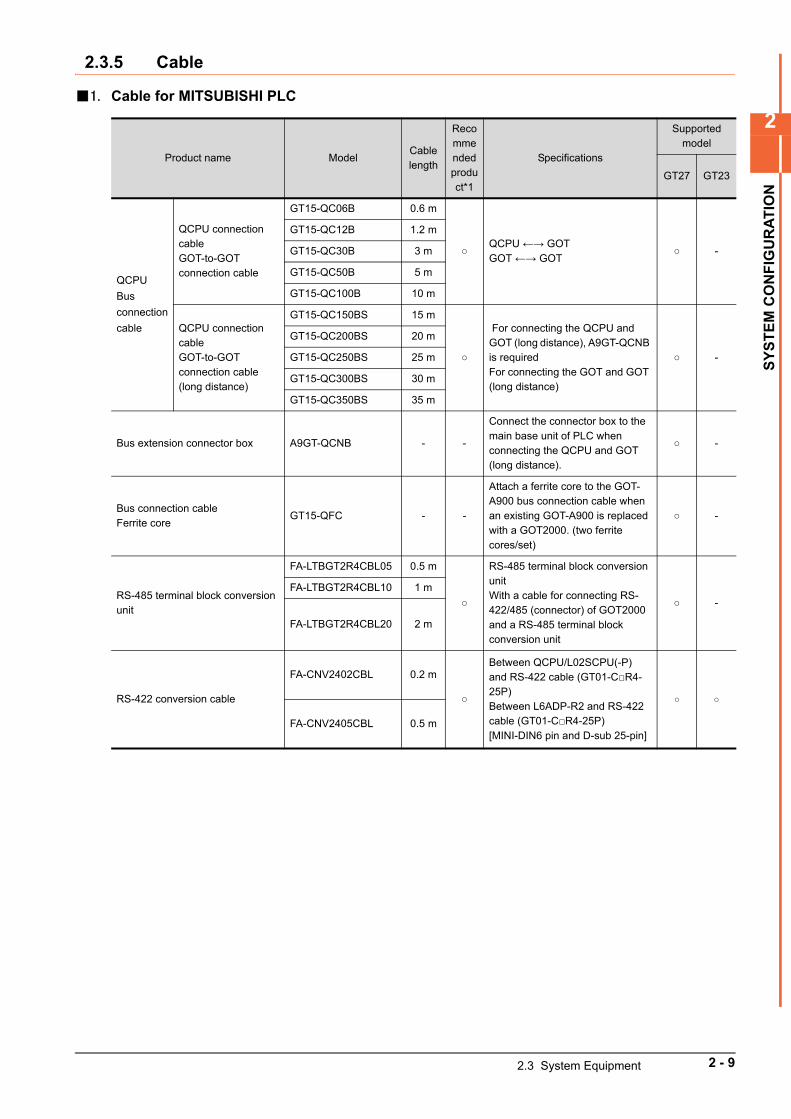
2.3.5 Cable
1. Cable for MITSUBISHI PLC
Product name ModelCable length
Recommended product*1
Specifications
Supported model
GT27 GT23
QCPU
Bus
connection
cable
QCPU connection cableGOT-to-GOT connection cable
GT15-QC06B 0.6 m
QCPU ←→ GOTGOT ←→ GOT
-
GT15-QC12B 1.2 m
GT15-QC30B 3 m
GT15-QC50B 5 m
GT15-QC100B 10 m
QCPU connection cableGOT-to-GOT connection cable(long distance)
GT15-QC150BS 15 m
For connecting the QCPU and GOT (long distance), A9GT-QCNB is requiredFor connecting the GOT and GOT (long distance)
-
GT15-QC200BS 20 m
GT15-QC250BS 25 m
GT15-QC300BS 30 m
GT15-QC350BS 35 m
Bus extension connector box A9GT-QCNB - -
Connect the connector box to the main base unit of PLC when connecting the QCPU and GOT (long distance).
-
Bus connection cableFerrite core
GT15-QFC - -
Attach a ferrite core to the GOT-A900 bus connection cable when an existing GOT-A900 is replaced with a GOT2000. (two ferrite cores/set)
-
RS-485 terminal block conversion unit
FA-LTBGT2R4CBL05 0.5 m
RS-485 terminal block conversion unitWith a cable for connecting RS-422/485 (connector) of GOT2000 and a RS-485 terminal block conversion unit
-
FA-LTBGT2R4CBL10 1 m
FA-LTBGT2R4CBL20 2 m
RS-422 conversion cable
FA-CNV2402CBL 0.2 m
Between QCPU/L02SCPU(-P) and RS-422 cable (GT01-CR4-25P)Between L6ADP-R2 and RS-422 cable (GT01-CR4-25P)[MINI-DIN6 pin and D-sub 25-pin]
FA-CNV2405CBL 0.5 m
2.3 System Equipment 2 - 9
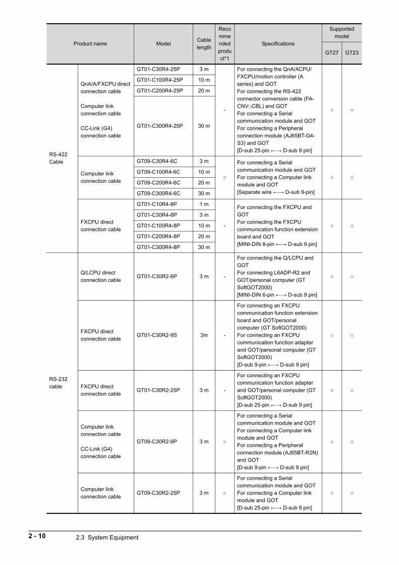
RS-422Cable
QnA/A/FXCPU direct connection cable
Computer link connection cable
CC-Link (G4) connection cable
GT01-C30R4-25P 3 m
-
For connecting the QnA/ACPU/FXCPU/motion controller (A series) and GOTFor connecting the RS-422 connector conversion cable (FA-CNVCBL) and GOTFor connecting a Serial communication module and GOTFor connecting a Peripheral connection module (AJ65BT-G4-S3) and GOT[D-sub 25-pin ←→ D-sub 9 pin]
GT01-C100R4-25P 10 m
GT01-C200R4-25P 20 m
GT01-C300R4-25P 30 m
Computer link connection cable
GT09-C30R4-6C 3 m
For connecting a Serial communication module and GOTFor connecting a Computer link module and GOT[Separate wire ←→ D-sub 9-pin]
GT09-C100R4-6C 10 m
GT09-C200R4-6C 20 m
GT09-C300R4-6C 30 m
FXCPU direct connection cable
GT01-C10R4-8P 1 m
-
For connecting the FXCPU and GOTFor connecting the FXCPU communication function extension board and GOT[MINI-DIN 8-pin ←→ D-sub 9 pin]
GT01-C30R4-8P 3 m
GT01-C100R4-8P 10 m
GT01-C200R4-8P 20 m
GT01-C300R4-8P 30 m
RS-232 cable
Q/LCPU direct connection cable
GT01-C30R2-6P 3 m -
For connecting the Q/LCPU and GOTFor connecting L6ADP-R2 and GOT/personal computer (GT SoftGOT2000)[MINI-DIN 6-pin ←→ D-sub 9 pin]
FXCPU direct connection cable
GT01-C30R2-9S 3m -
For connecting an FXCPU communication function extension board and GOT/personal computer (GT SoftGOT2000)For connecting an FXCPU communication function adapter and GOT/personal computer (GT SoftGOT2000)[D-sub 9-pin ←→ D-sub 9 pin]
FXCPU direct connection cable
GT01-C30R2-25P 3 m -
For connecting an FXCPU communication function adapter and GOT/personal computer (GT SoftGOT2000)[D-sub 25-pin ←→ D-sub 9 pin]
Computer link connection cable
CC-Link (G4) connection cable
GT09-C30R2-9P 3 m
For connecting a Serial communication module and GOTFor connecting a Computer link module and GOTFor connecting a Peripheral connection module (AJ65BT-R2N) and GOT[D-sub 9-pin ←→ D-sub 9 pin]
Computer link connection cable
GT09-C30R2-25P 3 m
For connecting a Serial communication module and GOTFor connecting a Computer link module and GOT[D-sub 25-pin ←→ D-sub 9 pin]
Product name ModelCable length
Recommended product*1
Specifications
Supported model
GT27 GT23
2 - 10 2.3 System Equipment
2
SY
ST
EM
CO
NF
IGU
RA
TIO
N
*1 FA-LTBGT2R4CBL, FA-CNV240CBL are developed by Mitsubishi Electric Engineering Company Limited and sold through
your local sales office.
The other products listed are developed by Mitsubishi Electric Systems & Service Co., LTD. and sold through your local sales
office.
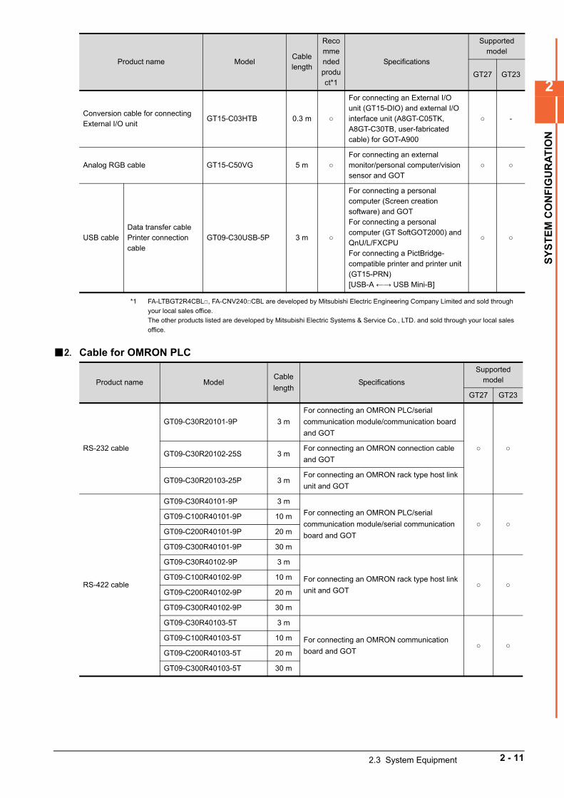
2. Cable for OMRON PLC
Conversion cable for connecting External I/O unit
GT15-C03HTB 0.3 m
For connecting an External I/O unit (GT15-DIO) and external I/O interface unit (A8GT-C05TK, A8GT-C30TB, user-fabricated cable) for GOT-A900
-
Analog RGB cable GT15-C50VG 5 m For connecting an external monitor/personal computer/vision sensor and GOT
USB cableData transfer cablePrinter connection cable
GT09-C30USB-5P 3 m
For connecting a personal computer (Screen creation software) and GOTFor connecting a personal computer (GT SoftGOT2000) and QnU/L/FXCPUFor connecting a PictBridge-compatible printer and printer unit (GT15-PRN)[USB-A ←→ USB Mini-B]
Product name ModelCable
lengthSpecifications
Supported model
GT27 GT23
RS-232 cable
GT09-C30R20101-9P 3 m
For connecting an OMRON PLC/serial
communication module/communication board
and GOT
GT09-C30R20102-25S 3 m
For connecting an OMRON connection cable
and GOT
GT09-C30R20103-25P 3 mFor connecting an OMRON rack type host link
unit and GOT
RS-422 cable
GT09-C30R40101-9P 3 m
For connecting an OMRON PLC/serial
communication module/serial communication
board and GOT
GT09-C100R40101-9P 10 m
GT09-C200R40101-9P 20 m
GT09-C300R40101-9P 30 m
GT09-C30R40102-9P 3 m
For connecting an OMRON rack type host link
unit and GOT
GT09-C100R40102-9P 10 m
GT09-C200R40102-9P 20 m
GT09-C300R40102-9P 30 m
GT09-C30R40103-5T 3 m
For connecting an OMRON communication
board and GOT
GT09-C100R40103-5T 10 m
GT09-C200R40103-5T 20 m
GT09-C300R40103-5T 30 m
Product name ModelCable length
Recommended product*1
Specifications
Supported model
GT27 GT23
2.3 System Equipment 2 - 11
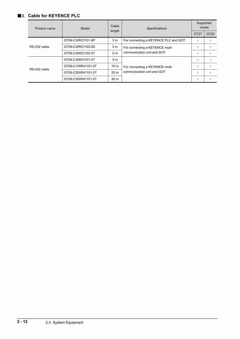
3. Cable for KEYENCE PLC
Product name ModelCable
lengthSpecifications
Supported model
GT27 GT23
RS-232 cable
GT09-C30R21101-6P 3 m For connecting a KEYENCE PLC and GOT
GT09-C30R21102-9S 3 m For connecting a KEYENCE multi-
communication unit and GOT
GT09-C30R21103-3T 3 m
RS-422 cable
GT09-C30R41101-5T 3 m
For connecting a KEYENCE multi-
communication unit and GOT
GT09-C100R41101-5T 10 m
GT09-C200R41101-5T 20 m
GT09-C300R41101-5T 30 m
2 - 12 2.3 System Equipment
2
SY
ST
EM
CO
NF
IGU
RA
TIO
N
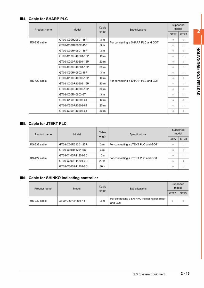
4. Cable for SHARP PLC
5. Cable for JTEKT PLC
6. Cable for SHINKO indicating controller
Product name ModelCable
lengthSpecifications
Supported model
GT27 GT23
RS-232 cableGT09-C30R20601-15P 3 m
For connecting a SHARP PLC and GOT
GT09-C30R20602-15P 3 m
RS-422 cable
GT09-C30R40601-15P 3 m
For connecting a SHARP PLC and GOT
GT09-C100R40601-15P 10 m
GT09-C200R40601-15P 20 m
GT09-C300R40601-15P 30 m
GT09-C30R40602-15P 3 m
GT09-C100R40602-15P 10 m
GT09-C200R40602-15P 20 m
GT09-C300R40602-15P 30 m
GT09-C30R40603-6T 3 m
GT09-C100R40603-6T 10 m
GT09-C200R40603-6T 20 m
GT09-C300R40603-6T 30 m
Product name ModelCable
lengthSpecifications
Supported model
GT27 GT23
RS-232 cable GT09-C30R21201-25P 3 m For connecting a JTEKT PLC and GOT
RS-422 cable
GT09-C30R41201-6C 3 m
For connecting a JTEKT PLC and GOT
GT09-C100R41201-6C 10 m
GT09-C200R41201-6C 20 m
GT09-C300R41201-6C 30m
Product name ModelCable
lengthSpecifications
Supported model
GT27 GT23
RS-232 cable GT09-C30R21401-4T 3 mFor connecting a SHINKO indicating controller
and GOT
2.3 System Equipment 2 - 13
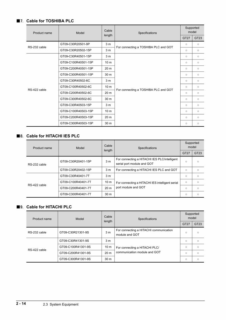
7. Cable for TOSHIBA PLC
8. Cable for HITACHI IES PLC
9. Cable for HITACHI PLC
Product name ModelCable
lengthSpecifications
Supported model
GT27 GT23
RS-232 cableGT09-C30R20501-9P 3 m
For connecting a TOSHIBA PLC and GOT
GT09-C30R20502-15P 3 m
RS-422 cable
GT09-C30R40501-15P 3 m
For connecting a TOSHIBA PLC and GOT
GT09-C100R40501-15P 10 m
GT09-C200R40501-15P 20 m
GT09-C300R40501-15P 30 m
GT09-C30R40502-6C 3 m
GT09-C100R40502-6C 10 m
GT09-C200R40502-6C 20 m
GT09-C300R40502-6C 30 m
GT09-C30R40503-15P 3 m
GT09-C100R40503-15P 10 m
GT09-C200R40503-15P 20 m
GT09-C300R40503-15P 30 m
Product name ModelCable
lengthSpecifications
Supported model
GT27 GT23
RS-232 cableGT09-C30R20401-15P 3 m
For connecting a HITACHI IES PLC/intelligent
serial port module and GOT
GT09-C30R20402-15P 3 m For connecting a HITACHI IES PLC and GOT
RS-422 cable
GT09-C30R40401-7T 3 m
For connecting a HITACHI IES intelligent serial
port module and GOT
GT09-C100R40401-7T 10 m
GT09-C200R40401-7T 20 m
GT09-C300R40401-7T 30 m
Product name ModelCable
lengthSpecifications
Supported model
GT27 GT23
RS-232 cable GT09-C30R21301-9S 3 mFor connecting a HITACHI communication
module and GOT
RS-422 cable
GT09-C30R41301-9S 3 m
For connecting a HITACHI PLC/
communication module and GOT
GT09-C100R41301-9S 10 m
GT09-C200R41301-9S 20 m
GT09-C300R41301-9S 30 m
2 - 14 2.3 System Equipment
2
SY
ST
EM
CO
NF
IGU
RA
TIO
N
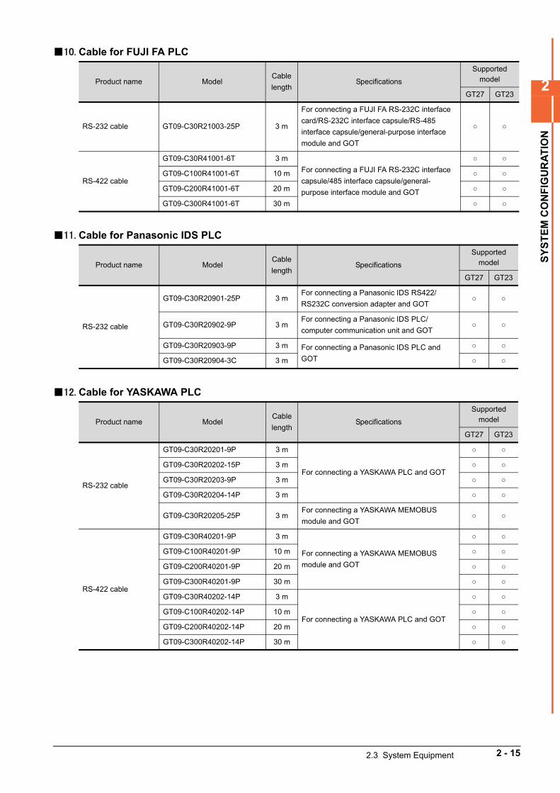
10. Cable for FUJI FA PLC
11. Cable for Panasonic IDS PLC
12. Cable for YASKAWA PLC
Product name ModelCable
lengthSpecifications
Supported model
GT27 GT23
RS-232 cable GT09-C30R21003-25P 3 m
For connecting a FUJI FA RS-232C interface
card/RS-232C interface capsule/RS-485
interface capsule/general-purpose interface
module and GOT
RS-422 cable
GT09-C30R41001-6T 3 m
For connecting a FUJI FA RS-232C interface
capsule/485 interface capsule/general-
purpose interface module and GOT
GT09-C100R41001-6T 10 m
GT09-C200R41001-6T 20 m
GT09-C300R41001-6T 30 m
Product name ModelCable
lengthSpecifications
Supported model
GT27 GT23
RS-232 cable
GT09-C30R20901-25P 3 mFor connecting a Panasonic IDS RS422/
RS232C conversion adapter and GOT
GT09-C30R20902-9P 3 mFor connecting a Panasonic IDS PLC/
computer communication unit and GOT
GT09-C30R20903-9P 3 m For connecting a Panasonic IDS PLC and
GOT
GT09-C30R20904-3C 3 m
Product name ModelCable
lengthSpecifications
Supported model
GT27 GT23
RS-232 cable
GT09-C30R20201-9P 3 m
For connecting a YASKAWA PLC and GOT
GT09-C30R20202-15P 3 m
GT09-C30R20203-9P 3 m
GT09-C30R20204-14P 3 m
GT09-C30R20205-25P 3 mFor connecting a YASKAWA MEMOBUS
module and GOT
RS-422 cable
GT09-C30R40201-9P 3 m
For connecting a YASKAWA MEMOBUS
module and GOT
GT09-C100R40201-9P 10 m
GT09-C200R40201-9P 20 m
GT09-C300R40201-9P 30 m
GT09-C30R40202-14P 3 m
For connecting a YASKAWA PLC and GOT
GT09-C100R40202-14P 10 m
GT09-C200R40202-14P 20 m
GT09-C300R40202-14P 30 m
2.3 System Equipment 2 - 15
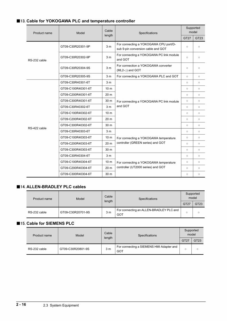
13. Cable for YOKOGAWA PLC and temperature controller
14. ALLEN-BRADLEY PLC cables
15. Cable for SIEMENS PLC
Product name ModelCable
lengthSpecifications
Supported model
GT27 GT23
RS-232 cable
GT09-C30R20301-9P 3 mFor connecting a YOKOGAWA CPU port/D-
sub 9-pin conversion cable and GOT
GT09-C30R20302-9P 3 mFor connecting a YOKOGAWA PC link module
and GOT
GT09-C30R20304-9S 3 mFor connection a YOKOGAWA converter
(ML2-) and GOT
GT09-C30R20305-9S 3 m For connecting a YOKOGAWA PLC and GOT
RS-422 cable
GT09-C30R40301-6T 3 m
For connecting a YOKOGAWA PC link module
and GOT
GT09-C100R40301-6T 10 m
GT09-C200R40301-6T 20 m
GT09-C300R40301-6T 30 m
GT09-C30R40302-6T 3 m
GT09-C100R40302-6T 10 m
GT09-C200R40302-6T 20 m
GT09-C300R40302-6T 30 m
GT09-C30R40303-6T 3 m
For connecting a YOKOGAWA temperature
controller (GREEN series) and GOT
GT09-C100R40303-6T 10 m
GT09-C200R40303-6T 20 m
GT09-C300R40303-6T 30 m
GT09-C30R40304-6T 3 m
For connecting a YOKOGAWA temperature
controller (UT2000 series) and GOT
GT09-C100R40304-6T 10 m
GT09-C200R40304-6T 20 m
GT09-C300R40304-6T 30 m
Product name ModelCable
lengthSpecifications
Supported model
GT27 GT23
RS-232 cable GT09-C30R20701-9S 3 mFor connecting an ALLEN-BRADLEY PLC and
GOT
Product name ModelCable
lengthSpecifications
Supported model
GT27 GT23
RS-232 cable GT09-C30R20801-9S 3 mFor connecting a SIEMENS HMI Adapter and
GOT
2 - 16 2.3 System Equipment
2
SY
ST
EM
CO
NF
IGU
RA
TIO
N
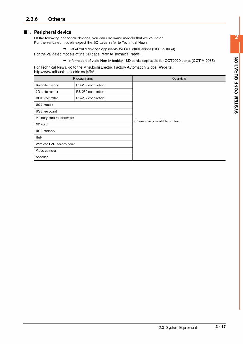
2.3.6 Others
1. Peripheral deviceOf the following peripheral devices, you can use some models that we validated.For the validated models expect the SD cads, refer to Technical News.
List of valid devices applicable for GOT2000 series (GOT-A-0064)For the validated models of the SD cads, refer to Technical News.
Information of valid Non-Mitsubishi SD cards applicable for GOT2000 series(GOT-A-0065)
For Technical News, go to the Mitsubishi Electric Factory Automation Global Website.http://www.mitsubishielectric.co.jp/fa/
Product name Overview
Barcode reader RS-232 connection
Commercially available product
2D code reader RS-232 connection
RFID controller RS-232 connection
USB mouse
USB keyboard
Memory card reader/writer
SD card
USB memory
Hub
Wireless LAN access point
Video camera
Speaker
2.3 System Equipment 2 - 17

2 - 18 2.3 System Equipment
3
SP
EC
IFIC
AT
ION
S
3. SPECIFICATIONS
3.1 General Specifications . . . . . . . . . . . . . . . . . . . . . . . . . . . . . . . . . 3 - 2
3.2 Performance Specifications . . . . . . . . . . . . . . . . . . . . . . . . . . . . 3 - 4
3.3 Specifications of Power Supply Section . . . . . . . . . . . . . . . . . 3 - 14
3.4 Battery Specifications . . . . . . . . . . . . . . . . . . . . . . . . . . . . . . . . 3 - 16
3 - 1
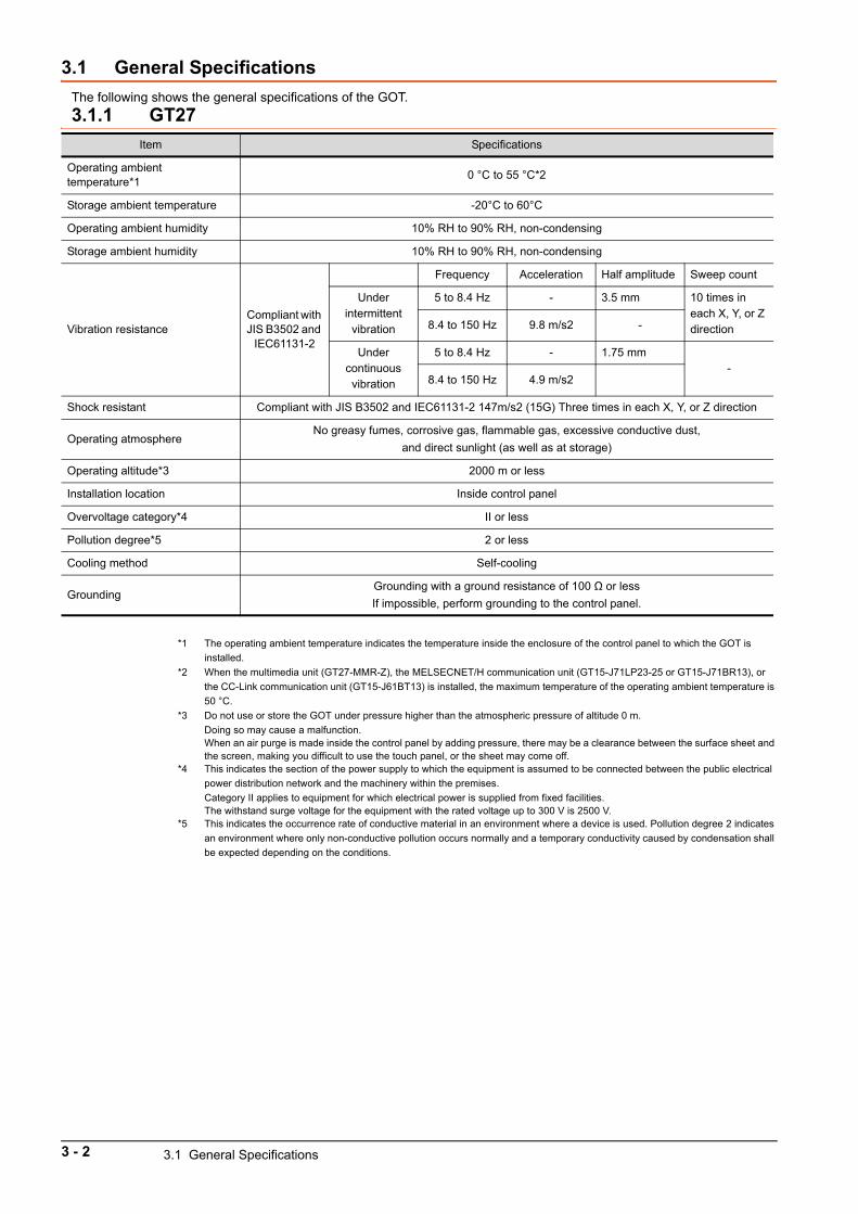
3.1 General Specifications
The following shows the general specifications of the GOT.
3.1.1 GT27
*1 The operating ambient temperature indicates the temperature inside the enclosure of the control panel to which the GOT is
installed.
*2 When the multimedia unit (GT27-MMR-Z), the MELSECNET/H communication unit (GT15-J71LP23-25 or GT15-J71BR13), or
the CC-Link communication unit (GT15-J61BT13) is installed, the maximum temperature of the operating ambient temperature is
50 °C.
*3 Do not use or store the GOT under pressure higher than the atmospheric pressure of altitude 0 m.
Doing so may cause a malfunction.When an air purge is made inside the control panel by adding pressure, there may be a clearance between the surface sheet and the screen, making you difficult to use the touch panel, or the sheet may come off.
*4 This indicates the section of the power supply to which the equipment is assumed to be connected between the public electrical
power distribution network and the machinery within the premises.
Category II applies to equipment for which electrical power is supplied from fixed facilities.The withstand surge voltage for the equipment with the rated voltage up to 300 V is 2500 V.
*5 This indicates the occurrence rate of conductive material in an environment where a device is used. Pollution degree 2 indicates
an environment where only non-conductive pollution occurs normally and a temporary conductivity caused by condensation shall
be expected depending on the conditions.
Item Specifications
Operating ambient temperature*1
0 °C to 55 °C*2
Storage ambient temperature -20°C to 60°C
Operating ambient humidity 10% RH to 90% RH, non-condensing
Storage ambient humidity 10% RH to 90% RH, non-condensing
Vibration resistanceCompliant with JIS B3502 and
IEC61131-2
Frequency Acceleration Half amplitude Sweep count
Under intermittent
vibration
5 to 8.4 Hz - 3.5 mm 10 times in each X, Y, or Z direction8.4 to 150 Hz 9.8 m/s2 -
Under continuous vibration
5 to 8.4 Hz - 1.75 mm-
8.4 to 150 Hz 4.9 m/s2
Shock resistant Compliant with JIS B3502 and IEC61131-2 147m/s2 (15G) Three times in each X, Y, or Z direction
Operating atmosphereNo greasy fumes, corrosive gas, flammable gas, excessive conductive dust,
and direct sunlight (as well as at storage)
Operating altitude*3 2000 m or less
Installation location Inside control panel
Overvoltage category*4 II or less
Pollution degree*5 2 or less
Cooling method Self-cooling
GroundingGrounding with a ground resistance of 100 Ω or less
If impossible, perform grounding to the control panel.
3 - 2 3.1 General Specifications
3
SP
EC
IFIC
AT
ION
S
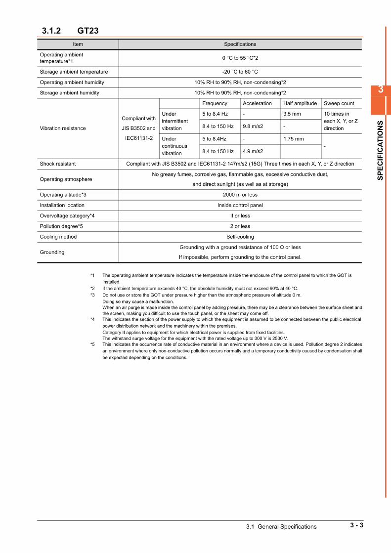
3.1.2 GT23
*1 The operating ambient temperature indicates the temperature inside the enclosure of the control panel to which the GOT is
installed.
*2 If the ambient temperature exceeds 40 °C, the absolute humidity must not exceed 90% at 40 °C.
*3 Do not use or store the GOT under pressure higher than the atmospheric pressure of altitude 0 m.
Doing so may cause a malfunction.When an air purge is made inside the control panel by adding pressure, there may be a clearance between the surface sheet and the screen, making you difficult to use the touch panel, or the sheet may come off.
*4 This indicates the section of the power supply to which the equipment is assumed to be connected between the public electrical
power distribution network and the machinery within the premises.
Category II applies to equipment for which electrical power is supplied from fixed facilities.The withstand surge voltage for the equipment with the rated voltage up to 300 V is 2500 V.
*5 This indicates the occurrence rate of conductive material in an environment where a device is used. Pollution degree 2 indicates
an environment where only non-conductive pollution occurs normally and a temporary conductivity caused by condensation shall
be expected depending on the conditions.
Item Specifications
Operating ambient temperature*1
0 °C to 55 °C*2
Storage ambient temperature -20 °C to 60 °C
Operating ambient humidity 10% RH to 90% RH, non-condensing*2
Storage ambient humidity 10% RH to 90% RH, non-condensing*2
Vibration resistance
Compliant with
JIS B3502 and
IEC61131-2
Frequency Acceleration Half amplitude Sweep count
Under intermittent vibration
5 to 8.4 Hz - 3.5 mm 10 times in each X, Y, or Z direction8.4 to 150 Hz 9.8 m/s2 -
Under continuous vibration
5 to 8.4Hz - 1.75 mm-
8.4 to 150 Hz 4.9 m/s2
Shock resistant Compliant with JIS B3502 and IEC61131-2 147m/s2 (15G) Three times in each X, Y, or Z direction
Operating atmosphereNo greasy fumes, corrosive gas, flammable gas, excessive conductive dust,
and direct sunlight (as well as at storage)
Operating altitude*3 2000 m or less
Installation location Inside control panel
Overvoltage category*4 II or less
Pollution degree*5 2 or less
Cooling method Self-cooling
GroundingGrounding with a ground resistance of 100 Ω or less
If impossible, perform grounding to the control panel.
3.1 General Specifications 3 - 3
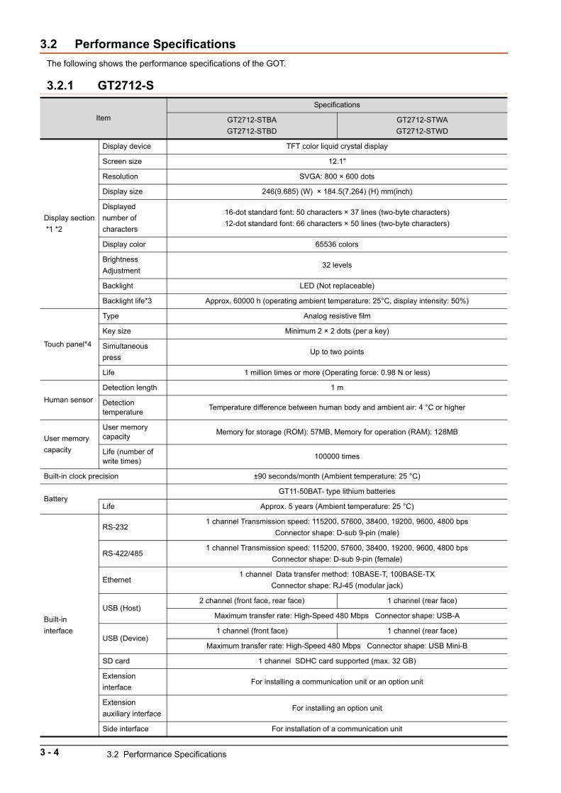
3.2 Performance Specifications
The following shows the performance specifications of the GOT.
3.2.1 GT2712-S
Item
Specifications
GT2712-STBA
GT2712-STBD
GT2712-STWA
GT2712-STWD
Display section
*1 *2
Display device TFT color liquid crystal display
Screen size 12.1"
Resolution SVGA: 800 × 600 dots
Display size 246(9.685) (W) × 184.5(7.264) (H) mm(inch)
Displayed
number of
characters
16-dot standard font: 50 characters × 37 lines (two-byte characters)
12-dot standard font: 66 characters × 50 lines (two-byte characters)
Display color 65536 colors
Brightness
Adjustment32 levels
Backlight LED (Not replaceable)
Backlight life*3 Approx. 60000 h (operating ambient temperature: 25°C, display intensity: 50%)
Touch panel*4
Type Analog resistive film
Key size Minimum 2 × 2 dots (per a key)
Simultaneous
pressUp to two points
Life 1 million times or more (Operating force: 0.98 N or less)
Human sensor
Detection length 1 m
Detection temperature
Temperature difference between human body and ambient air: 4 °C or higher
User memory
capacity
User memory capacity
Memory for storage (ROM): 57MB, Memory for operation (RAM): 128MB
Life (number of write times)
100000 times
Built-in clock precision ±90 seconds/month (Ambient temperature: 25 °C)
BatteryGT11-50BAT- type lithium batteries
Life Approx. 5 years (Ambient temperature: 25 °C)
Built-in
interface
RS-2321 channel Transmission speed: 115200, 57600, 38400, 19200, 9600, 4800 bps
Connector shape: D-sub 9-pin (male)
RS-422/4851 channel Transmission speed: 115200, 57600, 38400, 19200, 9600, 4800 bps
Connector shape: D-sub 9-pin (female)
Ethernet1 channel Data transfer method: 10BASE-T, 100BASE-TX
Connector shape: RJ-45 (modular jack)
USB (Host)2 channel (front face, rear face) 1 channel (rear face)
Maximum transfer rate: High-Speed 480 Mbps Connector shape: USB-A
USB (Device)1 channel (front face) 1 channel (rear face)
Maximum transfer rate: High-Speed 480 Mbps Connector shape: USB Mini-B
SD card 1 channel SDHC card supported (max. 32 GB)
Extension
interfaceFor installing a communication unit or an option unit
Extension
auxiliary interfaceFor installing an option unit
Side interface For installation of a communication unit
3 - 4 3.2 Performance Specifications
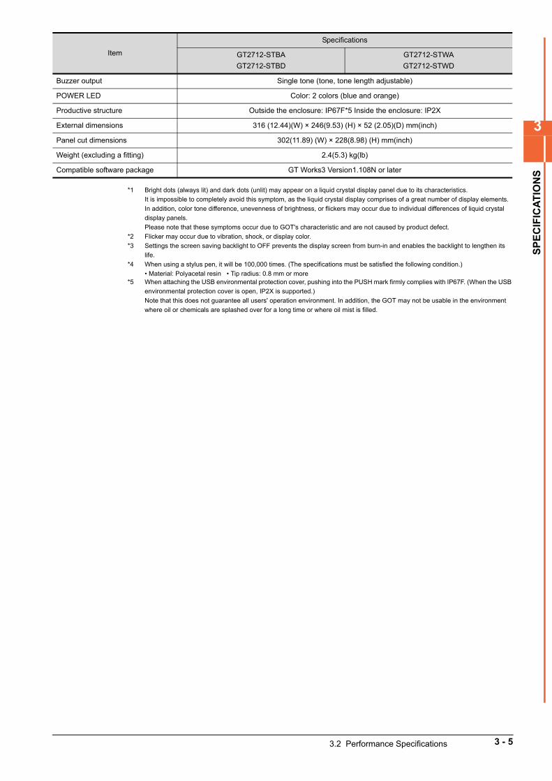
3
SP
EC
IFIC
AT
ION
S
*1 Bright dots (always lit) and dark dots (unlit) may appear on a liquid crystal display panel due to its characteristics.
It is impossible to completely avoid this symptom, as the liquid crystal display comprises of a great number of display elements.
In addition, color tone difference, unevenness of brightness, or flickers may occur due to individual differences of liquid crystal
display panels.
Please note that these symptoms occur due to GOT's characteristic and are not caused by product defect.
*2 Flicker may occur due to vibration, shock, or display color.
*3 Settings the screen saving backlight to OFF prevents the display screen from burn-in and enables the backlight to lengthen its
life.
*4 When using a stylus pen, it will be 100,000 times. (The specifications must be satisfied the following condition.)
• Material: Polyacetal resin • Tip radius: 0.8 mm or more*5 When attaching the USB environmental protection cover, pushing into the PUSH mark firmly complies with IP67F. (When the USB
environmental protection cover is open, IP2X is supported.)
Note that this does not guarantee all users' operation environment. In addition, the GOT may not be usable in the environment
where oil or chemicals are splashed over for a long time or where oil mist is filled.
Buzzer output Single tone (tone, tone length adjustable)
POWER LED Color: 2 colors (blue and orange)
Productive structure Outside the enclosure: IP67F*5 Inside the enclosure: IP2X
External dimensions 316 (12.44)(W) × 246(9.53) (H) × 52 (2.05)(D) mm(inch)
Panel cut dimensions 302(11.89) (W) × 228(8.98) (H) mm(inch)
Weight (excluding a fitting) 2.4(5.3) kg(lb)
Compatible software package GT Works3 Version1.108N or later
Item
Specifications
GT2712-STBA
GT2712-STBD
GT2712-STWA
GT2712-STWD
3.2 Performance Specifications 3 - 5
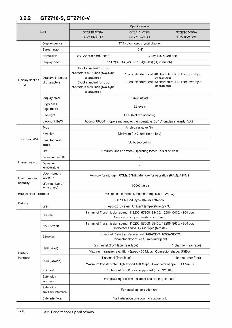
3.2.2 GT2710-S, GT2710-V
Item
Specifications
GT2710-STBA
GT2710-STBD
GT2710-VTBA
GT2710-VTBD
GT2710-VTWA
GT2710-VTWD
Display section
*1 *2
Display device TFT color liquid crystal display
Screen size 10.4"
Resolution SVGA: 800 × 600 dots VGA: 640 × 480 dots
Display size 211.2(8.315) (W) × 158.4(6.236) (H) mm(inch)
Displayed number
of characters
16-dot standard font: 50
characters × 37 lines (two-byte
characters)
12-dot standard font: 66
characters × 50 lines (two-byte
characters)
16-dot standard font: 40 characters × 30 lines (two-byte characters)
12-dot standard font: 53 characters × 40 lines (two-byte characters)
Display color 65536 colors
Brightness
Adjustment32 levels
Backlight LED (Not replaceable)
Backlight life*3 Approx. 60000 h (operating ambient temperature: 25 °C, display intensity: 50%)
Touch panel*4
Type Analog resistive film
Key size Minimum 2 × 2 dots (per a key)
Simultaneous
pressUp to two points
Life 1 million times or more (Operating force: 0.98 N or less)
Human sensor
Detection length -
Detection temperature
-
User memory
capacity
User memory capacity
Memory for storage (ROM): 57MB, Memory for operation (RAM): 128MB
Life (number of write times)
100000 times
Built-in clock precision ±90 seconds/month (Ambient temperature: 25 °C)
BatteryGT11-50BAT- type lithium batteries
Life Approx. 5 years (Ambient temperature: 25 °C)
Built-in
interface
RS-2321 channel Transmission speed: 115200, 57600, 38400, 19200, 9600, 4800 bps
Connector shape: D-sub 9-pin (male)
RS-422/4851 channel Transmission speed: 115200, 57600, 38400, 19200, 9600, 4800 bps
Connector shape: D-sub 9-pin (female)
Ethernet1 channel Data transfer method: 10BASE-T, 100BASE-TX
Connector shape: RJ-45 (modular jack)
USB (Host)2 channel (front face, rear face) 1 channel (rear face)
Maximum transfer rate: High-Speed 480 Mbps Connector shape: USB-A
USB (Device)1 channel (front face) 1 channel (rear face)
Maximum transfer rate: High-Speed 480 Mbps Connector shape: USB Mini-B
SD card 1 channel SDHC card supported (max. 32 GB)
Extension
interfaceFor installing a communication unit or an option unit
Extension
auxiliary interfaceFor installing an option unit
Side interface For installation of a communication unit
3 - 6 3.2 Performance Specifications
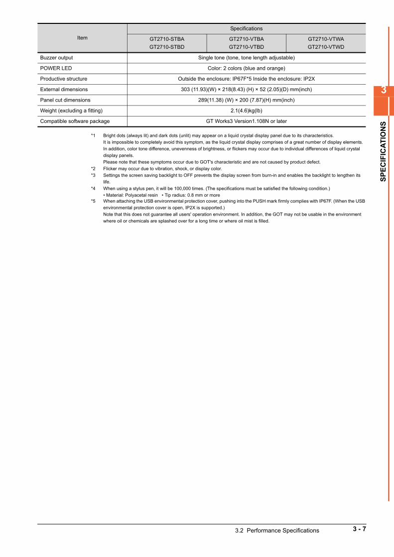
3
SP
EC
IFIC
AT
ION
S
*1 Bright dots (always lit) and dark dots (unlit) may appear on a liquid crystal display panel due to its characteristics.
It is impossible to completely avoid this symptom, as the liquid crystal display comprises of a great number of display elements.
In addition, color tone difference, unevenness of brightness, or flickers may occur due to individual differences of liquid crystal
display panels.
Please note that these symptoms occur due to GOT's characteristic and are not caused by product defect.
*2 Flicker may occur due to vibration, shock, or display color.
*3 Settings the screen saving backlight to OFF prevents the display screen from burn-in and enables the backlight to lengthen its
life.
*4 When using a stylus pen, it will be 100,000 times. (The specifications must be satisfied the following condition.)
• Material: Polyacetal resin • Tip radius: 0.8 mm or more*5 When attaching the USB environmental protection cover, pushing into the PUSH mark firmly complies with IP67F. (When the USB
environmental protection cover is open, IP2X is supported.)
Note that this does not guarantee all users' operation environment. In addition, the GOT may not be usable in the environment
where oil or chemicals are splashed over for a long time or where oil mist is filled.
Buzzer output Single tone (tone, tone length adjustable)
POWER LED Color: 2 colors (blue and orange)
Productive structure Outside the enclosure: IP67F*5 Inside the enclosure: IP2X
External dimensions 303 (11.93)(W) × 218(8.43) (H) × 52 (2.05)(D) mm(inch)
Panel cut dimensions 289(11.38) (W) × 200 (7.87)(H) mm(inch)
Weight (excluding a fitting) 2.1(4.6)kg(lb)
Compatible software package GT Works3 Version1.108N or later
Item
Specifications
GT2710-STBA
GT2710-STBD
GT2710-VTBA
GT2710-VTBD
GT2710-VTWA
GT2710-VTWD
3.2 Performance Specifications 3 - 7
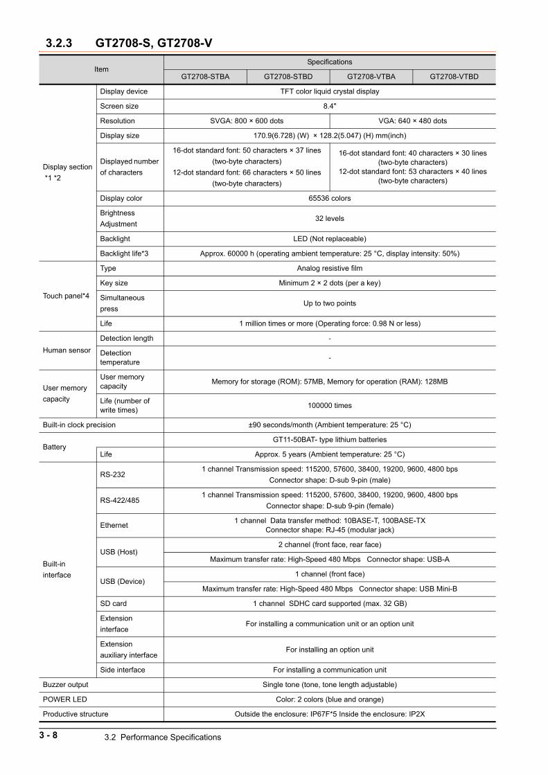
3.2.3 GT2708-S, GT2708-V
ItemSpecifications
GT2708-STBA GT2708-STBD GT2708-VTBA GT2708-VTBD
Display section
*1 *2
Display device TFT color liquid crystal display
Screen size 8.4"
Resolution SVGA: 800 × 600 dots VGA: 640 × 480 dots
Display size 170.9(6.728) (W) × 128.2(5.047) (H) mm(inch)
Displayed number
of characters
16-dot standard font: 50 characters × 37 lines
(two-byte characters)
12-dot standard font: 66 characters × 50 lines
(two-byte characters)
16-dot standard font: 40 characters × 30 lines (two-byte characters)
12-dot standard font: 53 characters × 40 lines (two-byte characters)
Display color 65536 colors
Brightness
Adjustment32 levels
Backlight LED (Not replaceable)
Backlight life*3 Approx. 60000 h (operating ambient temperature: 25 °C, display intensity: 50%)
Touch panel*4
Type Analog resistive film
Key size Minimum 2 × 2 dots (per a key)
Simultaneous
pressUp to two points
Life 1 million times or more (Operating force: 0.98 N or less)
Human sensor
Detection length -
Detection temperature
-
User memory
capacity
User memory capacity
Memory for storage (ROM): 57MB, Memory for operation (RAM): 128MB
Life (number of write times)
100000 times
Built-in clock precision ±90 seconds/month (Ambient temperature: 25 °C)
BatteryGT11-50BAT- type lithium batteries
Life Approx. 5 years (Ambient temperature: 25 °C)
Built-in
interface
RS-2321 channel Transmission speed: 115200, 57600, 38400, 19200, 9600, 4800 bps
Connector shape: D-sub 9-pin (male)
RS-422/4851 channel Transmission speed: 115200, 57600, 38400, 19200, 9600, 4800 bps
Connector shape: D-sub 9-pin (female)
Ethernet1 channel Data transfer method: 10BASE-T, 100BASE-TX
Connector shape: RJ-45 (modular jack)
USB (Host)2 channel (front face, rear face)
Maximum transfer rate: High-Speed 480 Mbps Connector shape: USB-A
USB (Device)1 channel (front face)
Maximum transfer rate: High-Speed 480 Mbps Connector shape: USB Mini-B
SD card 1 channel SDHC card supported (max. 32 GB)
Extension
interfaceFor installing a communication unit or an option unit
Extension
auxiliary interfaceFor installing an option unit
Side interface For installing a communication unit
Buzzer output Single tone (tone, tone length adjustable)
POWER LED Color: 2 colors (blue and orange)
Productive structure Outside the enclosure: IP67F*5 Inside the enclosure: IP2X
3 - 8 3.2 Performance Specifications
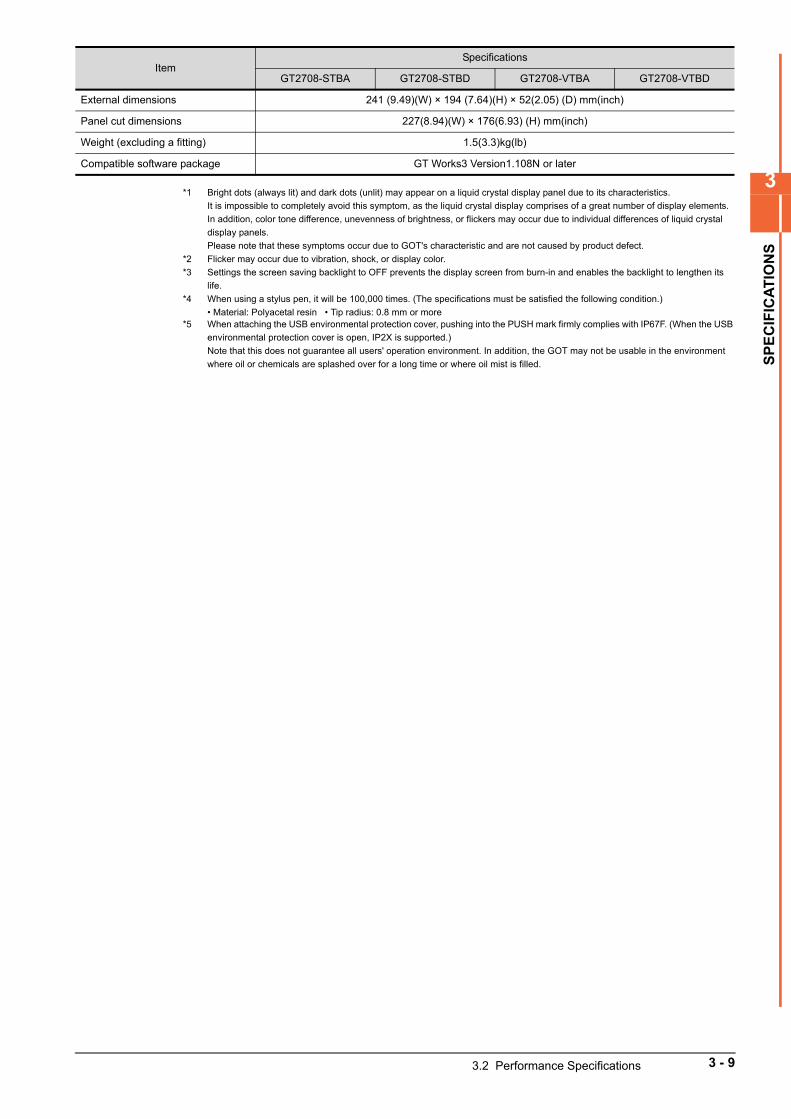
3
SP
EC
IFIC
AT
ION
S
*1 Bright dots (always lit) and dark dots (unlit) may appear on a liquid crystal display panel due to its characteristics.
It is impossible to completely avoid this symptom, as the liquid crystal display comprises of a great number of display elements.
In addition, color tone difference, unevenness of brightness, or flickers may occur due to individual differences of liquid crystal
display panels.
Please note that these symptoms occur due to GOT's characteristic and are not caused by product defect.
*2 Flicker may occur due to vibration, shock, or display color.
*3 Settings the screen saving backlight to OFF prevents the display screen from burn-in and enables the backlight to lengthen its
life.
*4 When using a stylus pen, it will be 100,000 times. (The specifications must be satisfied the following condition.)
• Material: Polyacetal resin • Tip radius: 0.8 mm or more*5 When attaching the USB environmental protection cover, pushing into the PUSH mark firmly complies with IP67F. (When the USB
environmental protection cover is open, IP2X is supported.)
Note that this does not guarantee all users' operation environment. In addition, the GOT may not be usable in the environment
where oil or chemicals are splashed over for a long time or where oil mist is filled.
External dimensions 241 (9.49)(W) × 194 (7.64)(H) × 52(2.05) (D) mm(inch)
Panel cut dimensions 227(8.94)(W) × 176(6.93) (H) mm(inch)
Weight (excluding a fitting) 1.5(3.3)kg(lb)
Compatible software package GT Works3 Version1.108N or later
ItemSpecifications
GT2708-STBA GT2708-STBD GT2708-VTBA GT2708-VTBD
3.2 Performance Specifications 3 - 9
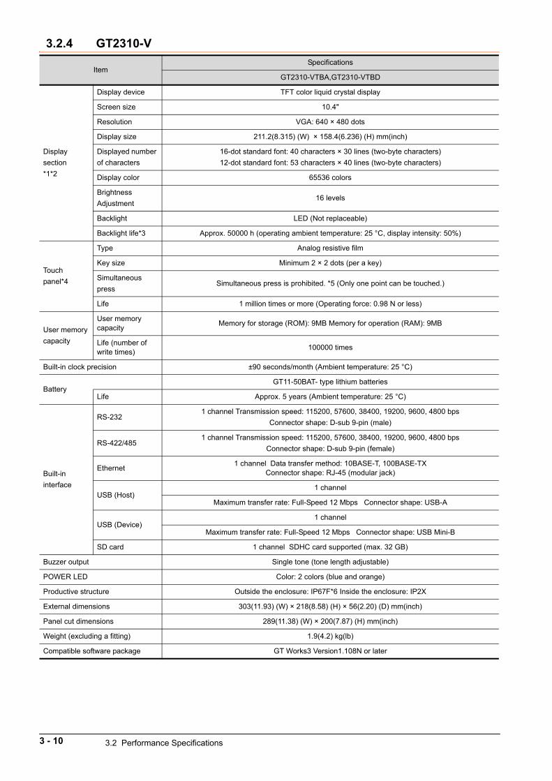
3.2.4 GT2310-V
ItemSpecifications
GT2310-VTBA,GT2310-VTBD
Display
section
*1*2
Display device TFT color liquid crystal display
Screen size 10.4"
Resolution VGA: 640 × 480 dots
Display size 211.2(8.315) (W) × 158.4(6.236) (H) mm(inch)
Displayed number
of characters
16-dot standard font: 40 characters × 30 lines (two-byte characters)
12-dot standard font: 53 characters × 40 lines (two-byte characters)
Display color 65536 colors
Brightness
Adjustment16 levels
Backlight LED (Not replaceable)
Backlight life*3 Approx. 50000 h (operating ambient temperature: 25 °C, display intensity: 50%)
Touch
panel*4
Type Analog resistive film
Key size Minimum 2 × 2 dots (per a key)
Simultaneous
pressSimultaneous press is prohibited. *5 (Only one point can be touched.)
Life 1 million times or more (Operating force: 0.98 N or less)
User memory
capacity
User memory capacity
Memory for storage (ROM): 9MB Memory for operation (RAM): 9MB
Life (number of write times)
100000 times
Built-in clock precision ±90 seconds/month (Ambient temperature: 25 °C)
BatteryGT11-50BAT- type lithium batteries
Life Approx. 5 years (Ambient temperature: 25 °C)
Built-in
interface
RS-2321 channel Transmission speed: 115200, 57600, 38400, 19200, 9600, 4800 bps
Connector shape: D-sub 9-pin (male)
RS-422/4851 channel Transmission speed: 115200, 57600, 38400, 19200, 9600, 4800 bps
Connector shape: D-sub 9-pin (female)
Ethernet1 channel Data transfer method: 10BASE-T, 100BASE-TX
Connector shape: RJ-45 (modular jack)
USB (Host)1 channel
Maximum transfer rate: Full-Speed 12 Mbps Connector shape: USB-A
USB (Device)1 channel
Maximum transfer rate: Full-Speed 12 Mbps Connector shape: USB Mini-B
SD card 1 channel SDHC card supported (max. 32 GB)
Buzzer output Single tone (tone length adjustable)
POWER LED Color: 2 colors (blue and orange)
Productive structure Outside the enclosure: IP67F*6 Inside the enclosure: IP2X
External dimensions 303(11.93) (W) × 218(8.58) (H) × 56(2.20) (D) mm(inch)
Panel cut dimensions 289(11.38) (W) × 200(7.87) (H) mm(inch)
Weight (excluding a fitting) 1.9(4.2) kg(lb)
Compatible software package GT Works3 Version1.108N or later
3 - 10 3.2 Performance Specifications
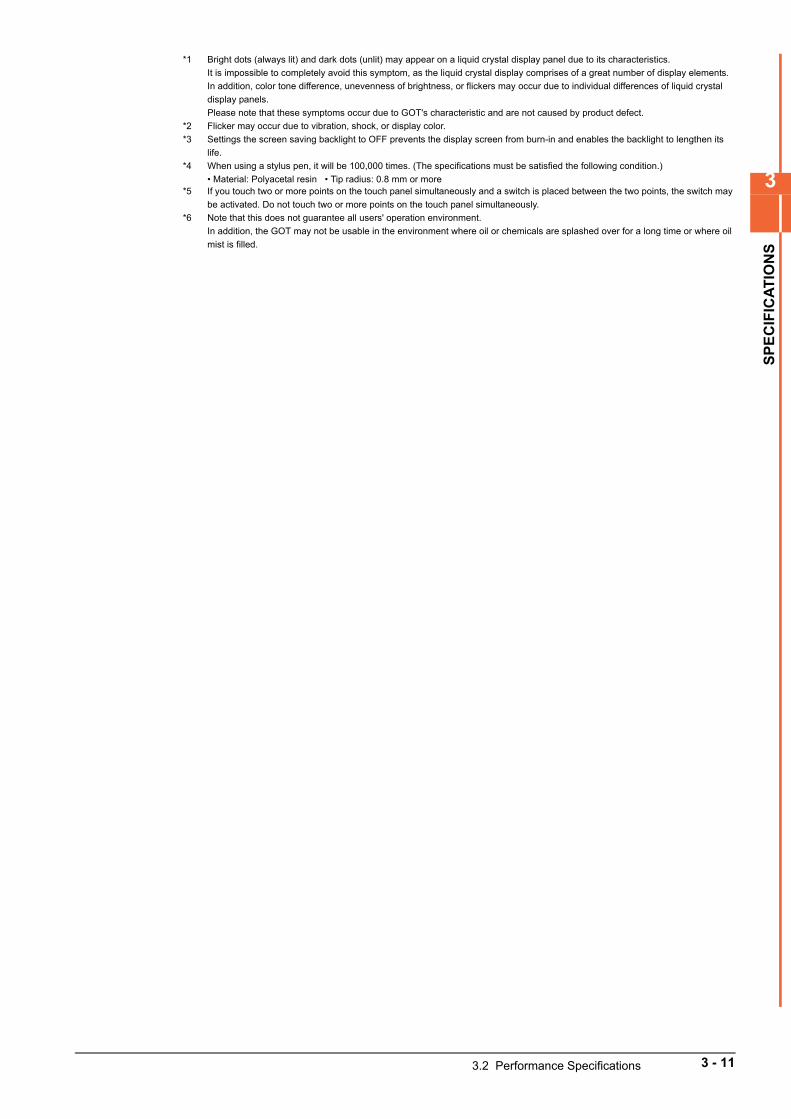
3
SP
EC
IFIC
AT
ION
S
*1 Bright dots (always lit) and dark dots (unlit) may appear on a liquid crystal display panel due to its characteristics.
It is impossible to completely avoid this symptom, as the liquid crystal display comprises of a great number of display elements.
In addition, color tone difference, unevenness of brightness, or flickers may occur due to individual differences of liquid crystal
display panels.
Please note that these symptoms occur due to GOT's characteristic and are not caused by product defect.
*2 Flicker may occur due to vibration, shock, or display color.
*3 Settings the screen saving backlight to OFF prevents the display screen from burn-in and enables the backlight to lengthen its
life.
*4 When using a stylus pen, it will be 100,000 times. (The specifications must be satisfied the following condition.)
• Material: Polyacetal resin • Tip radius: 0.8 mm or more*5 If you touch two or more points on the touch panel simultaneously and a switch is placed between the two points, the switch may
be activated. Do not touch two or more points on the touch panel simultaneously.
*6 Note that this does not guarantee all users' operation environment.
In addition, the GOT may not be usable in the environment where oil or chemicals are splashed over for a long time or where oil
mist is filled.
3.2 Performance Specifications 3 - 11
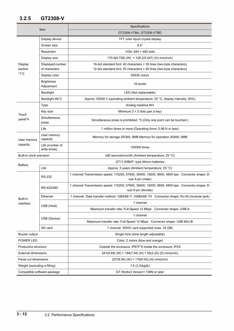
3.2.5 GT2308-V
ItemSpecifications
GT2308-VTBA, GT2308-VTBD
Display
section
*1*2
Display device TFT color liquid crystal display
Screen size 8.4"
Resolution VGA: 640 × 480 dots
Display size 170.9(6.728) (W) × 128.2(5.047) (H) mm(inch)
Displayed number
of characters
16-dot standard font: 40 characters × 30 lines (two-byte characters)
12-dot standard font: 53 characters × 40 lines (two-byte characters)
Display color 65536 colors
Brightness
Adjustment16 levels
Backlight LED (Not replaceable)
Backlight life*3 Approx. 50000 h (operating ambient temperature: 25 °C, display intensity: 50%)
Touch
panel*4
Type Analog resistive film
Key size Minimum 2 × 2 dots (per a key)
Simultaneous
pressSimultaneous press is prohibited. *5 (Only one point can be touched.)
Life 1 million times or more (Operating force: 0.98 N or less)
User memory
capacity
User memory capacity
Memory for storage (ROM): 9MB Memory for operation (RAM): 9MB
Life (number of write times)
100000 times
Built-in clock precision ±90 seconds/month (Ambient temperature: 25 °C)
BatteryGT11-50BAT- type lithium batteries
Life Approx. 5 years (Ambient temperature: 25 °C)
Built-in
interface
RS-2321 channel Transmission speed: 115200, 57600, 38400, 19200, 9600, 4800 bps Connector shape: D-
sub 9-pin (male)
RS-422/4851 channel Transmission speed: 115200, 57600, 38400, 19200, 9600, 4800 bps Connector shape: D-
sub 9-pin (female)
Ethernet 1 channel Data transfer method: 10BASE-T, 100BASE-TX Connector shape: RJ-45 (modular jack)
USB (Host)1 channel
Maximum transfer rate: Full-Speed 12 Mbps Connector shape: USB-A
USB (Device)1 channel
Maximum transfer rate: Full-Speed 12 Mbps Connector shape: USB Mini-B
SD card 1 channel SDHC card supported (max. 32 GB)
Buzzer output Single tone (tone length adjustable)
POWER LED Color: 2 colors (blue and orange)
Productive structure Outside the enclosure: IP67F*6 Inside the enclosure: IP2X
External dimensions 241(9.49) (W) × 194(7.64) (H) × 56(2.20) (D) mm(inch)
Panel cut dimensions 227(8.94) (W) × 176(6.93) (H) mm(inch)
Weight (excluding a fitting) 1.5 (3.3)kg(lb)
Compatible software package GT Works3 Version1.108N or later
3 - 12 3.2 Performance Specifications

3
SP
EC
IFIC
AT
ION
S
*1 Bright dots (always lit) and dark dots (unlit) may appear on a liquid crystal display panel due to its characteristics.
It is impossible to completely avoid this symptom, as the liquid crystal display comprises of a great number of display elements.
In addition, color tone difference, unevenness of brightness, or flickers may occur due to individual differences of liquid crystal
display panels.
Please note that these symptoms occur due to GOT's characteristic and are not caused by product defect.
*2 Flicker may occur due to vibration, shock, or display color.
*3 Settings the screen saving backlight to OFF prevents the display screen from burn-in and enables the backlight to lengthen its
life.
*4 When using a stylus pen, it will be 100,000 times. (The specifications must be satisfied the following condition.)
• Material: Polyacetal resin • Tip radius: 0.8 mm or more*5 If you touch two or more points on the touch panel simultaneously and a switch is placed between the two points, the switch may
be activated. Do not touch two or more points on the touch panel simultaneously.
*6 Note that this does not guarantee all users' operation environment.
In addition, the GOT may not be usable in the environment where oil or chemicals are splashed over for a long time or where oil
mist is filled.
3.2 Performance Specifications 3 - 13
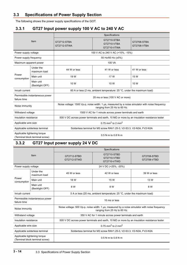
3.3 Specifications of Power Supply Section
The following shows the power supply specifications of the GOT.
3.3.1 GT27 Input power supply 100 V AC to 240 V AC
3.3.2 GT27 Input power supply 24 V DC
Item
Specifications
GT2712-STBA
GT2712-STWA
GT2710-STBA
GT2710-VTBA
GT2710-VTWA
GT2708-STBA
GT2708-VTBA
Power supply voltage 100 V AC to 240 V AC (+10%, -15%)
Power supply frequency 50 Hz/60 Hz (±5%)
Maximum apparent power 100 VA
Power
consumption
Under the
maximum load44 W or less 41 W or less 41 W or less
Main unit 19 W 17 W 15 W
Main unit
(Backlight OFF)10 W 10 W 10 W
Inrush current 60 A or less (2 ms, ambient temperature: 25 °C, under the maximum load)
Permissible instantaneous power
failure time20 ms or less (100 V AC or more)
Noise immunityNoise voltage: 1500 Vp-p, noise width: 1 μs, measured by a noise simulator with noise frequency
ranging from 25 Hz to 60 Hz.
Withstand voltage 1500 V AC for 1 minute across power terminals and earth
Insulation resistance 500 V DC across power terminals and earth, 10 MΩ or more by an insulation resistance tester
Applicable wire size 0.75 mm2 to 2 mm2
Applicable solderless terminal Solderless terminal for M3 screw RAV1.25-3, V2-S3.3, V2-N3A, FV2-N3A
Applicable tightening torque
(Terminal block terminal screw)0.5 N·m to 0.8 N·m
Item
Specifications
GT2712-STBDGT2712-STWD
GT2710-STBDGT2710-VTBDGT2710-VTWD
GT2708-STBDGT2708-VTBD
Power supply voltage 24 V DC (+25%, -20%)
Power consumption
Under the maximum load
45 W or less 42 W or less 39 W or less
Main unit 18 W 15 W 13 W
Main unit (Backlight OFF)
8 W 8 W 8 W
Inrush current 5 A or less (20 ms, ambient temperature: 25 °C, under the maximum load)
Permissible instantaneous power failure time
10 ms or less
Noise immunityNoise voltage: 500 Vp-p, noise width: 1 μs, measured by a noise simulator with noise frequency
ranging from 25 Hz to 60 Hz.
Withstand voltage 350 V AC for 1 minute across power terminals and earth
Insulation resistance 500 V DC across power terminals and earth, 10 MΩ or more by an insulation resistance tester
Applicable wire size 0.75 mm2 to 2 mm2
Applicable solderless terminal Solderless terminal for M3 screw RAV1.25-3, V2-S3.3, V2-N3A, FV2-N3A
Applicable tightening torque(Terminal block terminal screw)
0.5 N·m to 0.8 N·m
3 - 14 3.3 Specifications of Power Supply Section
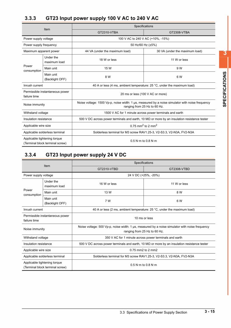
3
SP
EC
IFIC
AT
ION
S
3.3.3 GT23 Input power supply 100 V AC to 240 V AC
3.3.4 GT23 Input power supply 24 V DC
ItemSpecifications
GT2310-VTBA GT2308-VTBA
Power supply voltage 100 V AC to 240 V AC (+10%, -15%)
Power supply frequency 50 Hz/60 Hz (±5%)
Maximum apparent power 44 VA (under the maximum load) 30 VA (under the maximum load)
Power
consumption
Under the
maximum load18 W or less 11 W or less
Main unit 15 W 9 W
Main unit
(Backlight OFF)8 W 6 W
Inrush current 40 A or less (4 ms, ambient temperature: 25 °C, under the maximum load)
Permissible instantaneous power
failure time20 ms or less (100 V AC or more)
Noise immunityNoise voltage: 1500 Vp-p, noise width: 1 μs, measured by a noise simulator with noise frequency
ranging from 25 Hz to 60 Hz.
Withstand voltage 1500 V AC for 1 minute across power terminals and earth
Insulation resistance 500 V DC across power terminals and earth, 10 MΩ or more by an insulation resistance tester
Applicable wire size 0.75 mm2 to 2 mm2
Applicable solderless terminal Solderless terminal for M3 screw RAV1.25-3, V2-S3.3, V2-N3A, FV2-N3A
Applicable tightening torque
(Terminal block terminal screw)0.5 N·m to 0.8 N·m
ItemSpecifications
GT2310-VTBD GT2308-VTBD
Power supply voltage 24 V DC (+25%, -20%)
Power
consumption
Under the
maximum load16 W or less 11 W or less
Main unit 13 W 8 W
Main unit
(Backlight OFF)7 W 6 W
Inrush current 40 A or less (2 ms, ambient temperature: 25 °C, under the maximum load)
Permissible instantaneous power
failure time10 ms or less
Noise immunityNoise voltage: 500 Vp-p, noise width: 1 μs, measured by a noise simulator with noise frequency
ranging from 25 Hz to 60 Hz.
Withstand voltage 350 V AC for 1 minute across power terminals and earth
Insulation resistance 500 V DC across power terminals and earth, 10 MΩ or more by an insulation resistance tester
Applicable wire size 0.75 mm2 to 2 mm2
Applicable solderless terminal Solderless terminal for M3 screw RAV1.25-3, V2-S3.3, V2-N3A, FV2-N3A
Applicable tightening torque
(Terminal block terminal screw)0.5 N·m to 0.8 N·m
3.3 Specifications of Power Supply Section 3 - 15
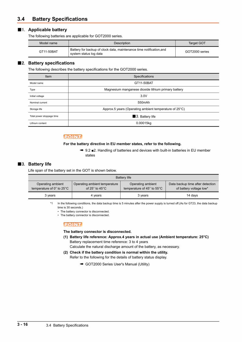
3.4 Battery Specifications
1. Applicable batteryThe following batteries are applicable for GOT2000 series.
2. Battery specificationsThe following describes the battery specifications for the GOT2000 series.
POINTPOINTPOINTFor the battery directive in EU member states, refer to the following.
9.2 2. Handling of batteries and devices with built-in batteries in EU member states
3. Battery lifeLife span of the battery set in the GOT is shown below.
*1 In the following conditions, the data backup time is 5 minutes after the power supply is turned off.(As for GT23, the data backup
time is 30 seconds.)
• The battery connector is disconnected.• The battery connector is disconnected.
POINTPOINTPOINTThe battery connector is disconnected.
(1) Battery life reference: Approx.4 years in actual use (Ambient temperature: 25°C)Battery replacement time reference: 3 to 4 yearsCalculate the natural discharge amount of the battery, as necessary.
(2) Check if the battery condition is normal within the utility.Refer to the following for the details of battery status display.
GOT2000 Series User's Manual (Utility)
Model name Description Target GOT
GT11-50BATBattery for backup of clock data, maintenance time notification,and system status log data
GOT2000 series
Item Specifications
Model name GT11-50BAT
Type Magnesium manganese dioxide lithium primary battery
Initial voltage 3.0V
Nominal current 550mAh
Storage life Approx.5 years (Operating ambient temperature of 25°C)
Total power stoppage time 3. Battery life
Lithium content 0.00015kg
Battery life
Operating ambient temperature of 0° to 25°C
Operating ambient temperature of 25° to 45°C
Operating ambient temperature of 45° to 55°C
Data backup time after detection of battery voltage low*
3 years 4 years 3 years 14 days
3 - 16 3.4 Battery Specifications
4
PA
RT
NA
ME
S A
ND
SE
TT
ING
S
4. PART NAMES AND SETTINGS
4.1 GT27. . . . . . . . . . . . . . . . . . . . . . . . . . . . . . . . . . . . . . . . . . . . . . . . 4 - 2
4.2 GT23. . . . . . . . . . . . . . . . . . . . . . . . . . . . . . . . . . . . . . . . . . . . . . . . 4 - 5
4 - 1
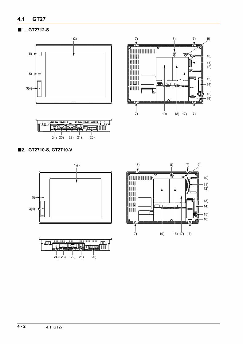
4.1 GT27
1. GT2712-S
2. GT2710-S, GT2710-V
1)2)
5)
23)
19)
8)
17)18)
9)
10)
11)12)
13)14)
15)
22) 21) 20)
7) 7)
7)
6)
7)
3)4)
24)
16)
13)
10)
11)12)
14)
15)
23) 22) 21) 20)
7) 7)19)
8)
18) 17)
9)7) 7)
24)
1)2)
5)
3)4)
16)
4 - 2 4.1 GT27
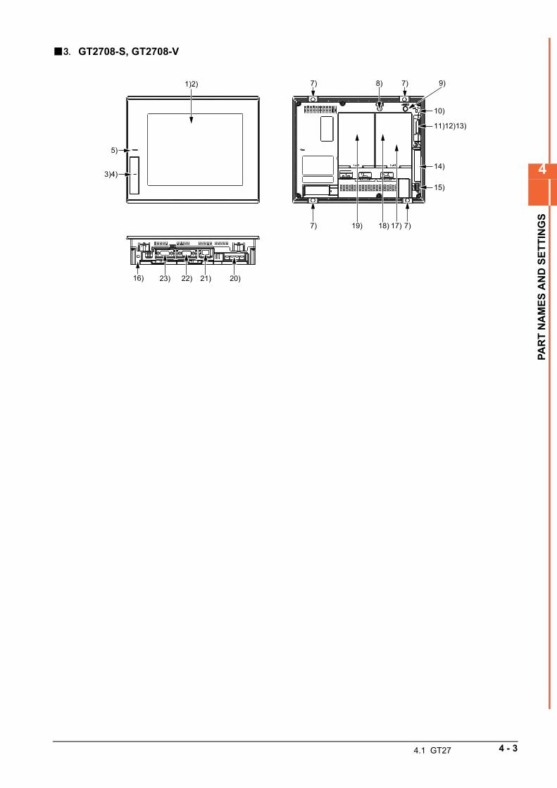
4
PA
RT
NA
ME
S A
ND
SE
TT
ING
S
3. GT2708-S, GT2708-V
10)
11)12)13)
17)
14)
15)
23) 22) 21) 20)
7) 7)19)
8)
18)
9)7) 7)1)2)
5)
3)4)
16)
4.1 GT27 4 - 3
4. PART NAMES AND SETTINGS OF GT27
No. Name Description
1) Display section Displays the utility and the user-created screen.
2) Touch panel For operating the touch switches in the utility and the user-created screen
3) USB interface (Host/front)
For connecting a USB mouse and a USB keyboard, transferring data, and storing data (Connector shape; TYPE-A)(GT2712-STBA/D, GT2710-STBA/D, GT2710-VTBA/D, GT2708-STBA/D, GT2708-VTBA/D only)
4) USB interface (Device/front)
For connecting a personal computer (Connector shape: Mini-B)
(GT2712-STBA/D, GT2710-STBA/D, GT2710-VTBA/D, GT2708-STBA/D, GT2708-
VTBA/D only)
5) POWER LED
Lit in blue : Power is properly supplied.Lit in orange : Screen savingBlinks in orange and blue: Backlight failureNot lit : Power is not supplied.
6) Human sensor Detects human movement. (GT2712 only)
7) Unit installation fitting Mounting fixtures for fixing the GOT to the control panel
8) Reset switch Hardware reset switch
9) S.MODE switch Used for OS installation at the GOT startup
10) SD card access LEDON: SD card installedBlink: SD card accessedOFF: SD card not installed or SD card installed but removal possible
11) SD card interface For installing an SD card
12) SD card cover
Has the function to switch the access to the SD card between enabled and disabled states.When the cover is opened: Access prohibitedWhen the cover is closed: Access allowed
13) Battery Space for housing the battery
14) Side interface For installing a communication unit
15) USB interface (Host/back)For connecting a USB mouse and a USB keyboard, transferring data, and storing data (Connector shape; TYPE-A)
16) Cable clamp mounting holeCable clamp mounting hole as a precaution against a disconnection of the USB cable (Recommended product: RSG-130-V0 of KITAGAWA INDUSTRIES CO.,LTD.)
17)Terminating resistor setting switch
(inside the cover)
Switches the terminating resistor for the RS-422/485 communication port between
used and unused states (initial setting (unused))
18) Extension auxiliary interface For installing an option unit
19) Extension interface For installing a communication unit or an option unit
20) Power terminal Power input terminal, LG terminal, FG terminal
21) Ethernet interfaceFor communicating with a controller or connecting a personal computer (Connector
shape: RJ-45 (modular jack))
22) RS-232 interface For communication with a controller (Connector shape: D-sub 9-pin (male))
23) RS-422/485 interface For communication with a controller (Connector shape: D-sub 9-pin (female))
24) USB interface (Device/back)For connecting a personal computer (Connector shape: Mini-B)
(GT2712-STWA/D, GT2710-VTWA/D only)
4 - 4 4.1 GT27
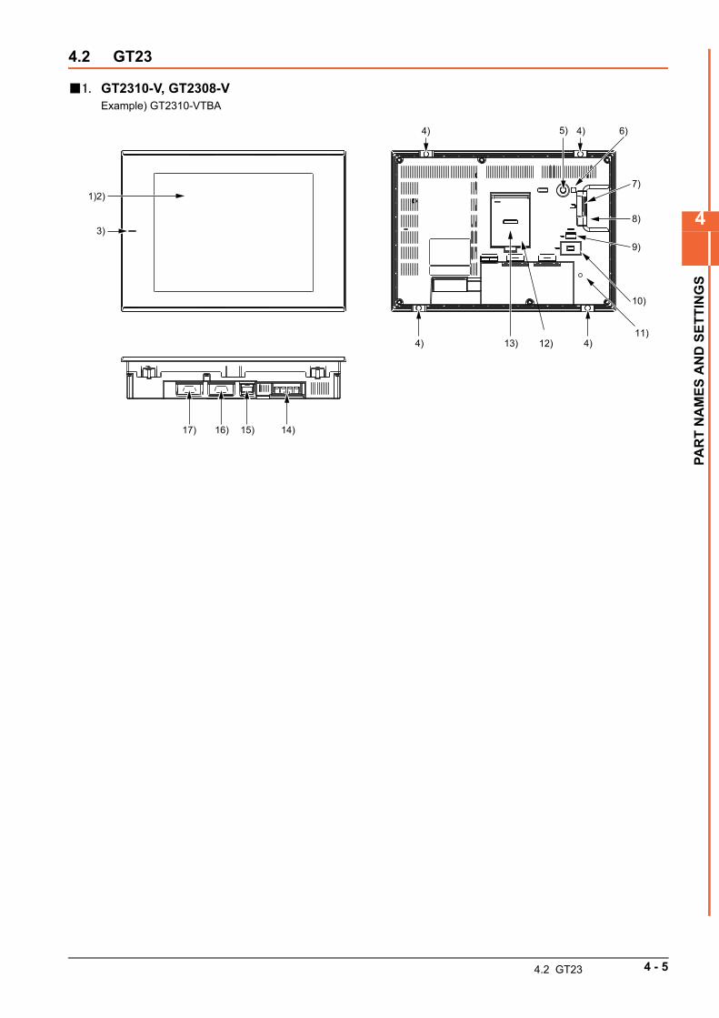
4
PA
RT
NA
ME
S A
ND
SE
TT
ING
S
4.2 GT23
1. GT2310-V, GT2308-VExample) GT2310-VTBA
1)2)
3)
5) 6)
7)
8)
10)
9)
17) 16) 15) 14)
4) 13) 4)
4) 4)
12)11)
4.2 GT23 4 - 5
2. PART NAMES AND SETTINGS
No. Name Description
1) Display section Displays the utility and the user-created screen.
2) Touch panel For operating the touch switches in the utility and the user-created screen
3) POWER LED
Lit in blue : Power is properly supplied.
Lit in orange : Screen saving
Blinks in orange and blue: Backlight failure
Not lit : Power is not supplied.
4) Unit installation fitting Mounting fixtures for fixing the GOT to the control panel
5) S.MODE switch Used for OS installation at the GOT startup
6) SD card access LED
ON: SD card installed
Blink: SD card accessed
OFF: SD card not installed or SD card installed but removal possible
7) SD card interface For installing an SD card
8) SD card cover
Has the function to switch the access to the SD card between enabled and
disabled states.
When the cover is opened: Access prohibited
When the cover is closed: Access allowed
9) USB interface (Host)For connecting a USB mouse and a USB keyboard, transferring data, and storing
data (Connector shape; TYPE-A)
10) USB interface (Device) For connecting a personal computer (Connector shape: Mini-B)
11) Cable clamp mounting holeCable clamp mounting hole as a precaution against a disconnection of the USB cable (Recommended product: RSG-130-V0 of KITAGAWA INDUSTRIES CO.,LTD.)
12)Terminating resistor setting switch (inside the cover)
Switches the terminating resistor for the RS-422/485 communication port between
used and unused states (initial setting (unused))
13) Battery Space for housing the battery
14) Power terminal Power input terminal, LG terminal, FG terminal
15) Ethernet interfaceFor communicating with a controller or connecting a personal computer
(Connector shape: RJ-45 (modular jack))
16) RS-232 interface For communication with a controller (Connector shape: D-sub 9-pin (male))
17) RS-422/485 interface For communication with a controller (Connector shape: D-sub 9-pin (female))
4 - 6 4.2 GT23
5
EM
C D
IRE
CT
IVE
AN
D L
OW
VO
LTA
GE
DIR
EC
TIV
E
5. EMC DIRECTIVE AND LOW VOLTAGE DIRECTIVE
5.1 Overview . . . . . . . . . . . . . . . . . . . . . . . . . . . . . . . . . . . . . . . . . . . . 5 - 2
5.2 EMC Directive Requirements. . . . . . . . . . . . . . . . . . . . . . . . . . . . 5 - 4
5.3 Low Voltage Directive Requirements . . . . . . . . . . . . . . . . . . . . 5 - 19
5 - 1
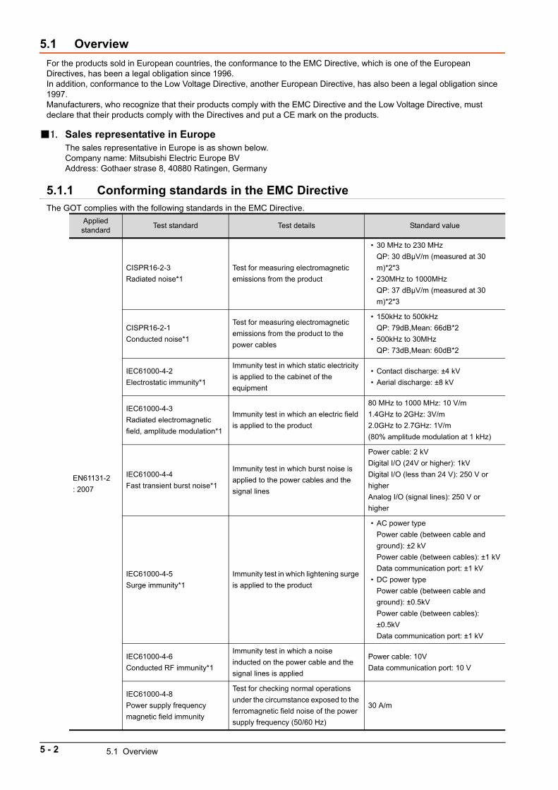
5.1 Overview
For the products sold in European countries, the conformance to the EMC Directive, which is one of the European Directives, has been a legal obligation since 1996.In addition, conformance to the Low Voltage Directive, another European Directive, has also been a legal obligation since 1997.Manufacturers, who recognize that their products comply with the EMC Directive and the Low Voltage Directive, must declare that their products comply with the Directives and put a CE mark on the products.
1. Sales representative in EuropeThe sales representative in Europe is as shown below.Company name: Mitsubishi Electric Europe BVAddress: Gothaer strase 8, 40880 Ratingen, Germany
5.1.1 Conforming standards in the EMC DirectiveThe GOT complies with the following standards in the EMC Directive.
Applied standard
Test standard Test details Standard value
EN61131-2
: 2007
CISPR16-2-3
Radiated noise*1
Test for measuring electromagnetic
emissions from the product
• 30 MHz to 230 MHz
QP: 30 dBμV/m (measured at 30
m)*2*3
• 230MHz to 1000MHz
QP: 37 dBμV/m (measured at 30
m)*2*3
CISPR16-2-1
Conducted noise*1
Test for measuring electromagnetic
emissions from the product to the
power cables
• 150kHz to 500kHz
QP: 79dB,Mean: 66dB*2
• 500kHz to 30MHz
QP: 73dB,Mean: 60dB*2
IEC61000-4-2
Electrostatic immunity*1
Immunity test in which static electricity
is applied to the cabinet of the
equipment
• Contact discharge: ±4 kV
• Aerial discharge: ±8 kV
IEC61000-4-3
Radiated electromagnetic
field, amplitude modulation*1
Immunity test in which an electric field
is applied to the product
80 MHz to 1000 MHz: 10 V/m
1.4GHz to 2GHz: 3V/m
2.0GHz to 2.7GHz: 1V/m
(80% amplitude modulation at 1 kHz)
IEC61000-4-4
Fast transient burst noise*1
Immunity test in which burst noise is
applied to the power cables and the
signal lines
Power cable: 2 kV
Digital I/O (24V or higher): 1kV
Digital I/O (less than 24 V): 250 V or
higher
Analog I/O (signal lines): 250 V or
higher
IEC61000-4-5
Surge immunity*1
Immunity test in which lightening surge
is applied to the product
• AC power type
Power cable (between cable and
ground): ±2 kV
Power cable (between cables): ±1 kV
Data communication port: ±1 kV
• DC power type
Power cable (between cable and
ground): ±0.5kV
Power cable (between cables):
±0.5kV
Data communication port: ±1 kV
IEC61000-4-6
Conducted RF immunity*1
Immunity test in which a noise
inducted on the power cable and the
signal lines is applied
Power cable: 10V
Data communication port: 10 V
IEC61000-4-8
Power supply frequency
magnetic field immunity
Test for checking normal operations
under the circumstance exposed to the
ferromagnetic field noise of the power
supply frequency (50/60 Hz)
30 A/m
5 - 2 5.1 Overview
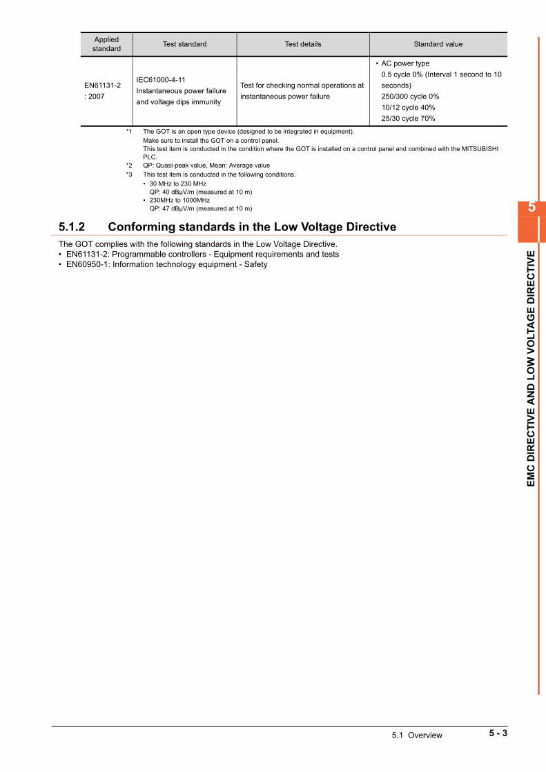
5
EM
C D
IRE
CT
IVE
AN
D L
OW
VO
LTA
GE
DIR
EC
TIV
E
*1 The GOT is an open type device (designed to be integrated in equipment).
Make sure to install the GOT on a control panel.This test item is conducted in the condition where the GOT is installed on a control panel and combined with the MITSUBISHI PLC.
*2 QP: Quasi-peak value, Mean: Average value
*3 This test item is conducted in the following conditions.
• 30 MHz to 230 MHzQP: 40 dBμV/m (measured at 10 m)
• 230MHz to 1000MHzQP: 47 dBμV/m (measured at 10 m)
5.1.2 Conforming standards in the Low Voltage DirectiveThe GOT complies with the following standards in the Low Voltage Directive.• EN61131-2: Programmable controllers - Equipment requirements and tests• EN60950-1: Information technology equipment - Safety
EN61131-2
: 2007
IEC61000-4-11
Instantaneous power failure
and voltage dips immunity
Test for checking normal operations at
instantaneous power failure
• AC power type
0.5 cycle 0% (Interval 1 second to 10
seconds)
250/300 cycle 0%
10/12 cycle 40%
25/30 cycle 70%
Applied standard
Test standard Test details Standard value
5.1 Overview 5 - 3
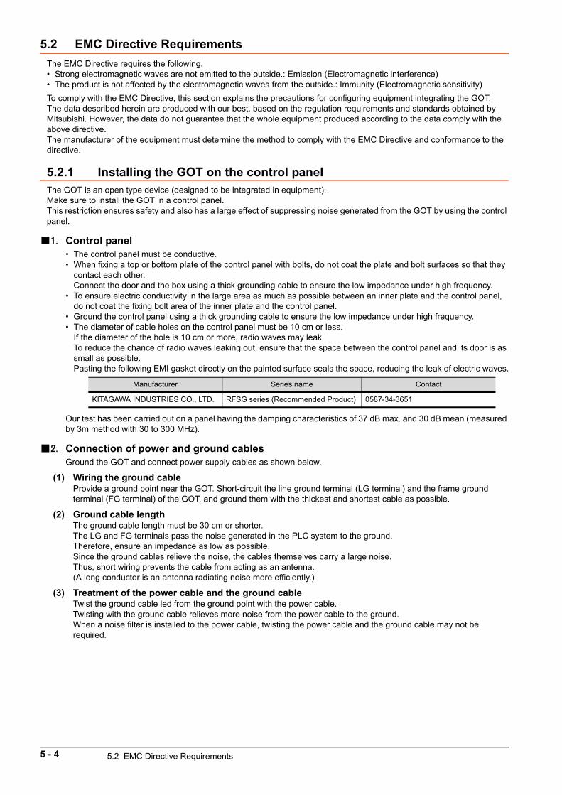
5.2 EMC Directive Requirements
The EMC Directive requires the following.• Strong electromagnetic waves are not emitted to the outside.: Emission (Electromagnetic interference)• The product is not affected by the electromagnetic waves from the outside.: Immunity (Electromagnetic sensitivity)
To comply with the EMC Directive, this section explains the precautions for configuring equipment integrating the GOT.The data described herein are produced with our best, based on the regulation requirements and standards obtained by Mitsubishi. However, the data do not guarantee that the whole equipment produced according to the data comply with the above directive.The manufacturer of the equipment must determine the method to comply with the EMC Directive and conformance to the directive.
5.2.1 Installing the GOT on the control panelThe GOT is an open type device (designed to be integrated in equipment).Make sure to install the GOT in a control panel.This restriction ensures safety and also has a large effect of suppressing noise generated from the GOT by using the control panel.
1. Control panel• The control panel must be conductive.• When fixing a top or bottom plate of the control panel with bolts, do not coat the plate and bolt surfaces so that they
contact each other.Connect the door and the box using a thick grounding cable to ensure the low impedance under high frequency.
• To ensure electric conductivity in the large area as much as possible between an inner plate and the control panel, do not coat the fixing bolt area of the inner plate and the control panel.
• Ground the control panel using a thick grounding cable to ensure the low impedance under high frequency.• The diameter of cable holes on the control panel must be 10 cm or less.
If the diameter of the hole is 10 cm or more, radio waves may leak.To reduce the chance of radio waves leaking out, ensure that the space between the control panel and its door is as small as possible.Pasting the following EMI gasket directly on the painted surface seals the space, reducing the leak of electric waves.
Our test has been carried out on a panel having the damping characteristics of 37 dB max. and 30 dB mean (measured by 3m method with 30 to 300 MHz).
2. Connection of power and ground cablesGround the GOT and connect power supply cables as shown below.
(1) Wiring the ground cableProvide a ground point near the GOT. Short-circuit the line ground terminal (LG terminal) and the frame ground terminal (FG terminal) of the GOT, and ground them with the thickest and shortest cable as possible.
(2) Ground cable lengthThe ground cable length must be 30 cm or shorter.The LG and FG terminals pass the noise generated in the PLC system to the ground.Therefore, ensure an impedance as low as possible.Since the ground cables relieve the noise, the cables themselves carry a large noise.Thus, short wiring prevents the cable from acting as an antenna.(A long conductor is an antenna radiating noise more efficiently.)
(3) Treatment of the power cable and the ground cableTwist the ground cable led from the ground point with the power cable.Twisting with the ground cable relieves more noise from the power cable to the ground.When a noise filter is installed to the power cable, twisting the power cable and the ground cable may not be required.
Manufacturer Series name Contact
KITAGAWA INDUSTRIES CO., LTD. RFSG series (Recommended Product) 0587-34-3651
5 - 4 5.2 EMC Directive Requirements
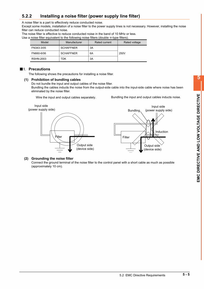
5
EM
C D
IRE
CT
IVE
AN
D L
OW
VO
LTA
GE
DIR
EC
TIV
E
5.2.2 Installing a noise filter (power supply line filter)A noise filter is a part to effectively reduce conducted noise.Except some models, installation of a noise filter to the power supply lines is not necessary. However, installing the noise filter can reduce conducted noise.The noise filter is effective to reduce conducted noise in the band of 10 MHz or less.Use a noise filter equivalent to the following noise filters (double π-type filters).
1. PrecautionsThe following shows the precautions for installing a noise filter.
(1) Prohibition of bundling cablesDo not bundle the input and output cables of the noise filter.Bundling the cables inducts the noise from the output-side cable into the input-side cable where noise has been eliminated by the noise filter.
(2) Grounding the noise filterConnect the ground terminal of the noise filter to the control panel with a short cable as much as possible (approximately 10 cm).
Model Manufacturer Rated current Rated voltage
FN343-3/05 SCHAFFNER 3A
250VFN660-6/06 SCHAFFNER 6A
RSHN-2003 TDK 3A
Input side (power supply side)
Output side (device side)
Filter
Wire the input and output cables separately.
Filter
Input side (power supply side)
Induction
Output side (device side)
Bundling the input and output cables inducts noise.
Bundling
5.2 EMC Directive Requirements 5 - 5
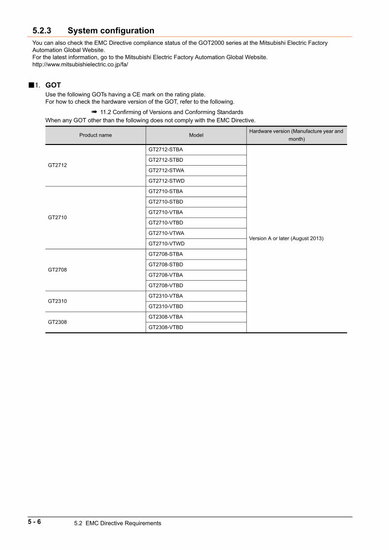
5.2.3 System configurationYou can also check the EMC Directive compliance status of the GOT2000 series at the Mitsubishi Electric Factory Automation Global Website.For the latest information, go to the Mitsubishi Electric Factory Automation Global Website.http://www.mitsubishielectric.co.jp/fa/
1. GOTUse the following GOTs having a CE mark on the rating plate.For how to check the hardware version of the GOT, refer to the following.
11.2 Confirming of Versions and Conforming StandardsWhen any GOT other than the following does not comply with the EMC Directive.
Product name ModelHardware version (Manufacture year and
month)
GT2712
GT2712-STBA
Version A or later (August 2013)
GT2712-STBD
GT2712-STWA
GT2712-STWD
GT2710
GT2710-STBA
GT2710-STBD
GT2710-VTBA
GT2710-VTBD
GT2710-VTWA
GT2710-VTWD
GT2708
GT2708-STBA
GT2708-STBD
GT2708-VTBA
GT2708-VTBD
GT2310GT2310-VTBA
GT2310-VTBD
GT2308GT2308-VTBA
GT2308-VTBD
5 - 6 5.2 EMC Directive Requirements
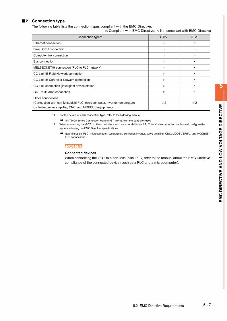
5
EM
C D
IRE
CT
IVE
AN
D L
OW
VO
LTA
GE
DIR
EC
TIV
E
2. Connection typeThe following table lists the connection types compliant with the EMC Directive.
: Compliant with EMC Directive, ×: Not compliant with EMC Directive
*1 For the details of each connection type, refer to the following manual.
GOT2000 Series Connection Manual (GT Works3) for the controller used
*2 When connecting the GOT to other controllers such as a non-Mitsubishi PLC, fabricate connection cables and configure the
system following the EMC Directive specifications.
Non-Mitsubishi PLC, microcomputer, temperature controller, inverter, servo amplifier, CNC, MODBUS/RTU, and MODBUS/TCP connections
POINTPOINTPOINTConnected devices
When connecting the GOT to a non-Mitsubishi PLC, refer to the manual about the EMC Directive compliance of the connected device (such as a PLC and a microcomputer).
Connection type*1 GT27 GT23
Ethernet connection
Direct CPU connection
Computer link connection
Bus connection ×
MELSECNET/H connection (PLC to PLC network) ×
CC-Link IE Field Network connection ×
CC-Link IE Controller Network connection ×
CC-Link connection (Intelligent device station) ×
GOT multi-drop connection × ×
Other connections
(Connection with non-Mitsubishi PLC, microcomputer, inverter, temperature
controller, servo amplifier, CNC, and MODBUS equipment)
*2 *2
5.2 EMC Directive Requirements 5 - 7
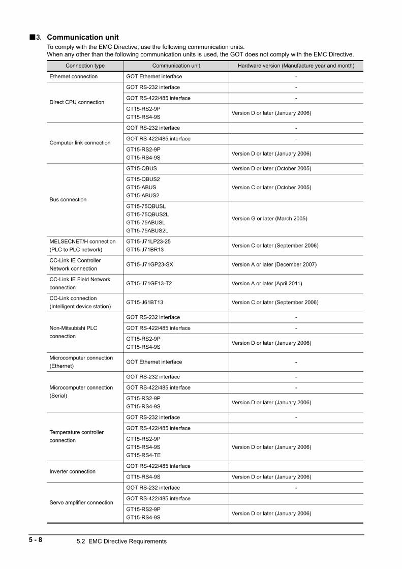
3. Communication unitTo comply with the EMC Directive, use the following communication units.When any other than the following communication units is used, the GOT does not comply with the EMC Directive.
Connection type Communication unit Hardware version (Manufacture year and month)
Ethernet connection GOT Ethernet interface -
Direct CPU connection
GOT RS-232 interface -
GOT RS-422/485 interface -
GT15-RS2-9P
GT15-RS4-9SVersion D or later (January 2006)
Computer link connection
GOT RS-232 interface -
GOT RS-422/485 interface -
GT15-RS2-9P
GT15-RS4-9SVersion D or later (January 2006)
Bus connection
GT15-QBUS Version D or later (October 2005)
GT15-QBUS2
GT15-ABUS
GT15-ABUS2
Version C or later (October 2005)
GT15-75QBUSL
GT15-75QBUS2L
GT15-75ABUSL
GT15-75ABUS2L
Version G or later (March 2005)
MELSECNET/H connection
(PLC to PLC network)
GT15-J71LP23-25
GT15-J71BR13Version C or later (September 2006)
CC-Link IE Controller
Network connectionGT15-J71GP23-SX Version A or later (December 2007)
CC-Link IE Field Network
connectionGT15-J71GF13-T2 Version A or later (April 2011)
CC-Link connection
(Intelligent device station)GT15-J61BT13 Version C or later (September 2006)
Non-Mitsubishi PLC
connection
GOT RS-232 interface -
GOT RS-422/485 interface -
GT15-RS2-9P
GT15-RS4-9SVersion D or later (January 2006)
Microcomputer connection
(Ethernet)GOT Ethernet interface -
Microcomputer connection
(Serial)
GOT RS-232 interface -
GOT RS-422/485 interface -
GT15-RS2-9P
GT15-RS4-9SVersion D or later (January 2006)
Temperature controller
connection
GOT RS-232 interface -
GOT RS-422/485 interface
GT15-RS2-9P
GT15-RS4-9S
GT15-RS4-TE
Version D or later (January 2006)
Inverter connectionGOT RS-422/485 interface
GT15-RS4-9S Version D or later (January 2006)
Servo amplifier connection
GOT RS-232 interface -
GOT RS-422/485 interface
GT15-RS2-9P
GT15-RS4-9SVersion D or later (January 2006)
5 - 8 5.2 EMC Directive Requirements
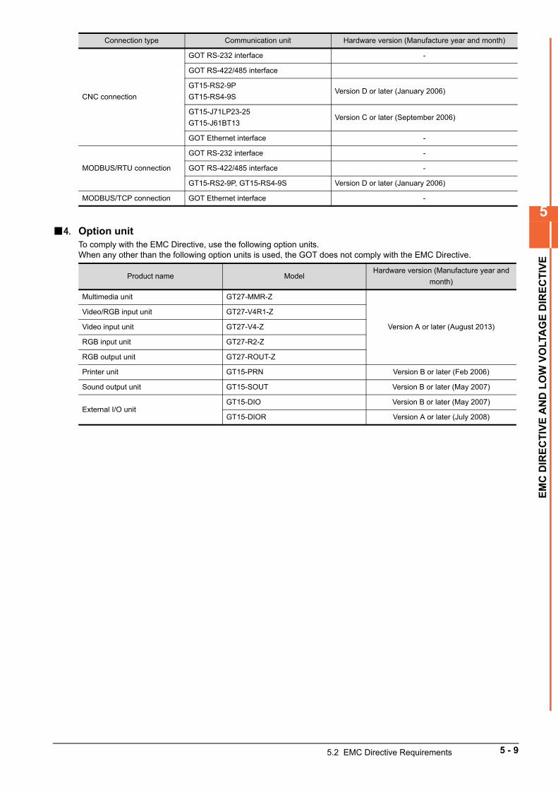
5
EM
C D
IRE
CT
IVE
AN
D L
OW
VO
LTA
GE
DIR
EC
TIV
E
4. Option unitTo comply with the EMC Directive, use the following option units.When any other than the following option units is used, the GOT does not comply with the EMC Directive.
CNC connection
GOT RS-232 interface -
GOT RS-422/485 interface
GT15-RS2-9P
GT15-RS4-9SVersion D or later (January 2006)
GT15-J71LP23-25
GT15-J61BT13Version C or later (September 2006)
GOT Ethernet interface -
MODBUS/RTU connection
GOT RS-232 interface -
GOT RS-422/485 interface -
GT15-RS2-9P, GT15-RS4-9S Version D or later (January 2006)
MODBUS/TCP connection GOT Ethernet interface -
Product name ModelHardware version (Manufacture year and
month)
Multimedia unit GT27-MMR-Z
Version A or later (August 2013)
Video/RGB input unit GT27-V4R1-Z
Video input unit GT27-V4-Z
RGB input unit GT27-R2-Z
RGB output unit GT27-ROUT-Z
Printer unit GT15-PRN Version B or later (Feb 2006)
Sound output unit GT15-SOUT Version B or later (May 2007)
External I/O unitGT15-DIO Version B or later (May 2007)
GT15-DIOR Version A or later (July 2008)
Connection type Communication unit Hardware version (Manufacture year and month)
5.2 EMC Directive Requirements 5 - 9
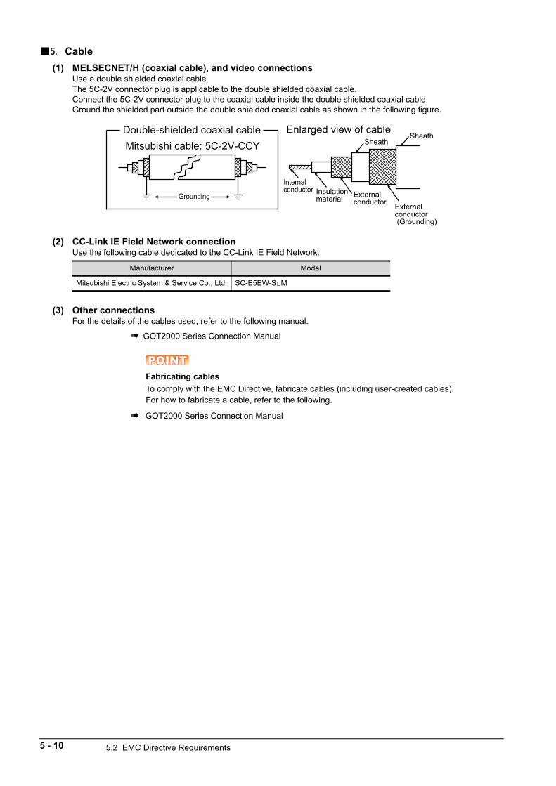
5. Cable
(1) MELSECNET/H (coaxial cable), and video connectionsUse a double shielded coaxial cable.The 5C-2V connector plug is applicable to the double shielded coaxial cable.Connect the 5C-2V connector plug to the coaxial cable inside the double shielded coaxial cable.Ground the shielded part outside the double shielded coaxial cable as shown in the following figure.
(2) CC-Link IE Field Network connectionUse the following cable dedicated to the CC-Link IE Field Network.
(3) Other connectionsFor the details of the cables used, refer to the following manual.
GOT2000 Series Connection Manual
POINTPOINTPOINTFabricating cables
To comply with the EMC Directive, fabricate cables (including user-created cables).For how to fabricate a cable, refer to the following.
GOT2000 Series Connection Manual
Manufacturer Model
Mitsubishi Electric System & Service Co., Ltd. SC-E5EW-SM
Grounding
Mitsubishi cable: 5C-2V-CCYDouble-shielded coaxial cable
Internal conductor Insulation
material External conductor
Sheath
External conductor (Grounding)
SheathEnlarged view of cable
5 - 10 5.2 EMC Directive Requirements
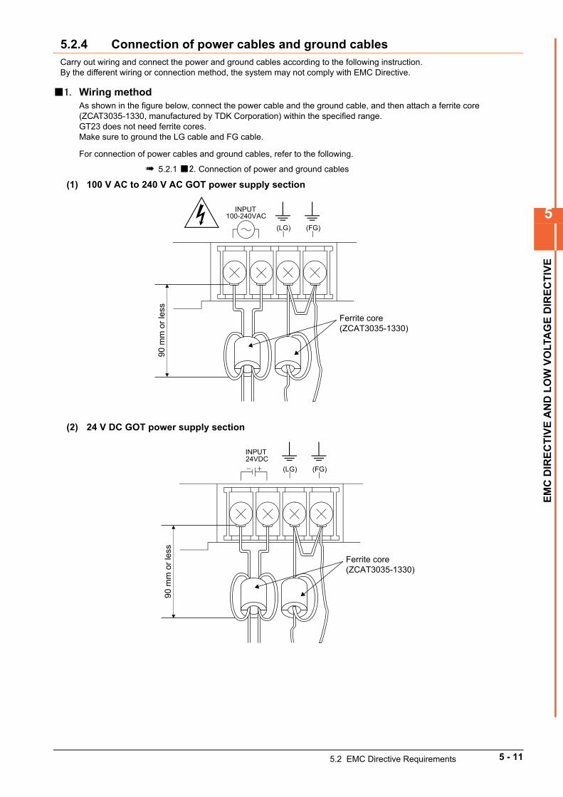
5
EM
C D
IRE
CT
IVE
AN
D L
OW
VO
LTA
GE
DIR
EC
TIV
E
5.2.4 Connection of power cables and ground cablesCarry out wiring and connect the power and ground cables according to the following instruction.By the different wiring or connection method, the system may not comply with EMC Directive.
1. Wiring methodAs shown in the figure below, connect the power cable and the ground cable, and then attach a ferrite core (ZCAT3035-1330, manufactured by TDK Corporation) within the specified range.GT23 does not need ferrite cores.Make sure to ground the LG cable and FG cable.
For connection of power cables and ground cables, refer to the following.
5.2.1 2. Connection of power and ground cables
(1) 100 V AC to 240 V AC GOT power supply section
(2) 24 V DC GOT power supply section
INPUT 100-240VAC
(LG) (FG)
90 m
m o
r les
s
Ferrite core(ZCAT3035-1330)
INPUT 24VDC+- (LG) (FG)
90 m
m o
r les
s
Ferrite core(ZCAT3035-1330)
5.2 EMC Directive Requirements 5 - 11
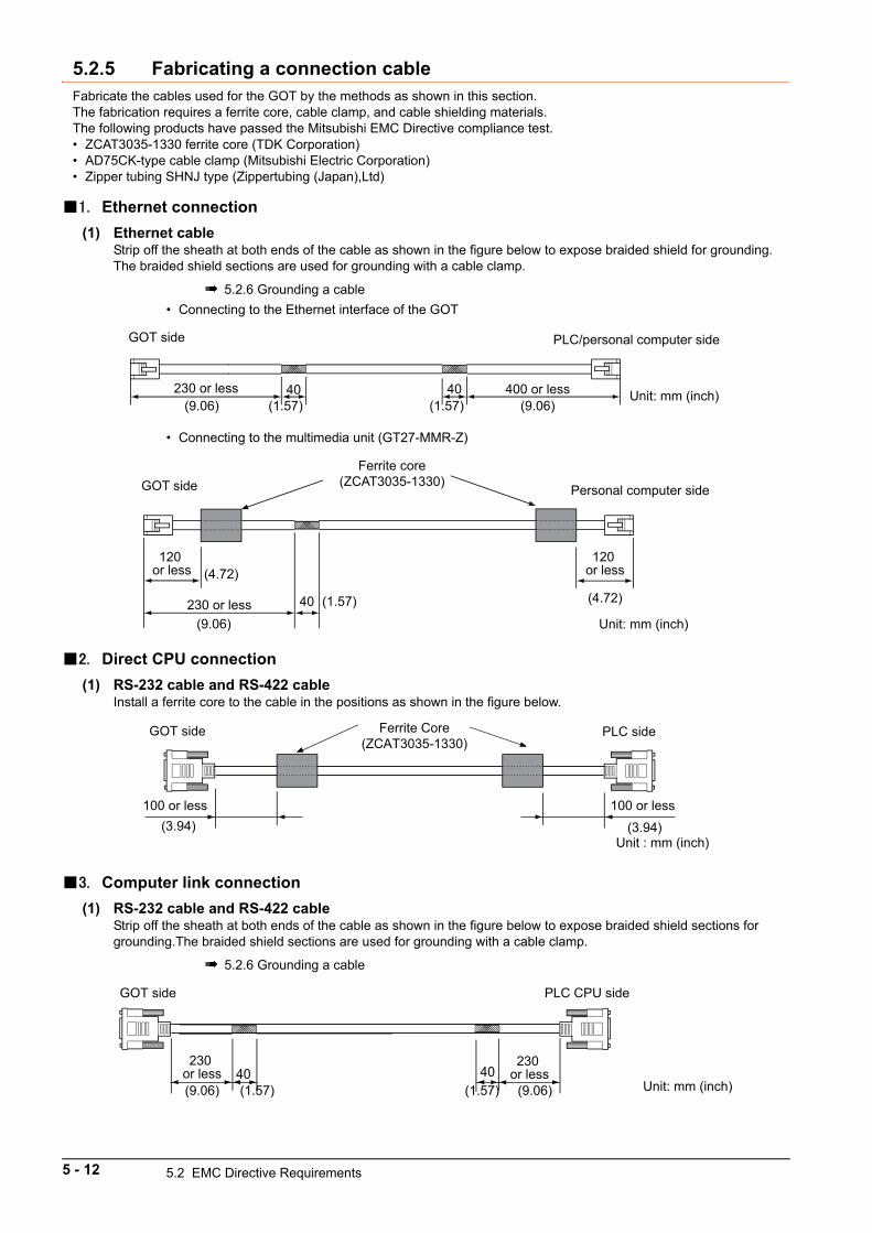
5.2.5 Fabricating a connection cableFabricate the cables used for the GOT by the methods as shown in this section.The fabrication requires a ferrite core, cable clamp, and cable shielding materials.The following products have passed the Mitsubishi EMC Directive compliance test.• ZCAT3035-1330 ferrite core (TDK Corporation)• AD75CK-type cable clamp (Mitsubishi Electric Corporation)• Zipper tubing SHNJ type (Zippertubing (Japan),Ltd)
1. Ethernet connection
(1) Ethernet cableStrip off the sheath at both ends of the cable as shown in the figure below to expose braided shield for grounding. The braided shield sections are used for grounding with a cable clamp.
5.2.6 Grounding a cable
• Connecting to the Ethernet interface of the GOT
• Connecting to the multimedia unit (GT27-MMR-Z)
2. Direct CPU connection
(1) RS-232 cable and RS-422 cableInstall a ferrite core to the cable in the positions as shown in the figure below.
3. Computer link connection
(1) RS-232 cable and RS-422 cableStrip off the sheath at both ends of the cable as shown in the figure below to expose braided shield sections for grounding.The braided shield sections are used for grounding with a cable clamp.
5.2.6 Grounding a cable
PLC/personal computer sideGOT side
230 or less 40 40 400 or less Unit: mm (inch)(9.06) (1.57) (1.57) (9.06)
120 or less
Personal computer side
Ferrite core (ZCAT3035-1330) GOT side
230 or less 40
Unit: mm (inch)
120 or less(4.72)
(4.72)
(9.06)
(1.57)
100 or less
Unit : mm (inch)
GOT side PLC sideFerrite Core(ZCAT3035-1330)
(3.94)
100 or less (3.94)
230 or less 40
230 or less
Unit: mm (inch)
GOT side PLC CPU side
40(9.06) (1.57) (1.57) (9.06)
5 - 12 5.2 EMC Directive Requirements
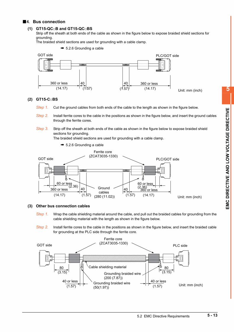
5
EM
C D
IRE
CT
IVE
AN
D L
OW
VO
LTA
GE
DIR
EC
TIV
E
4. Bus connection
(1) GT15-QCB and GT15-QCBSStrip off the sheath at both ends of the cable as shown in the figure below to expose braided shield sections for grounding.The braided shield sections are used for grounding with a cable clamp.
5.2.6 Grounding a cable
(2) GT15-CBS
Step 1. Cut the ground cables from both ends of the cable to the length as shown in the figure below.
Step 2. Install ferrite cores to the cable in the positions as shown in the figure below, and insert the ground cables through the ferrite cores.
Step 3. Strip off the sheath at both ends of the cable as shown in the figure below to expose braided shield sections for grounding.The braided shield sections are used for grounding with a cable clamp.
5.2.6 Grounding a cable
(3) Other bus connection cables
Step 1. Wrap the cable shielding material around the cable, and pull out the braided cables for grounding from the cable shielding material with the length as shown in the figure below.
Step 2. Install ferrite cores to the cable in the positions as shown in the figure below, and insert the braided cable for grounding at the PLC side through the ferrite core.
GOT side
40 40
PLC/GOT side
Unit: mm (inch)
360 or less360 or less(14.17) (14.17)(1.57) (1.57)
(14.17) (14.17)
(2.36) (2.36)
Ferrite core (ZCAT3035-1330)
360 or less 40 40Ground cables
(280 (11.02))
60 or less
GOT side
60 or less
360 or less
Unit: mm (inch)
PLC/GOT side
(1.57) (1.57)
80
GOT side PLC side
40 or lessUnit: mm (inch)
Ferrite core (ZCAT3035-1330)
Grounding braided wire (50(1.97))
Grounding braided wire (200 (7.87))
Cable shielding material 80
40 or less(1.57)
(3.15)
(1.57)
(3.15)
5.2 EMC Directive Requirements 5 - 13
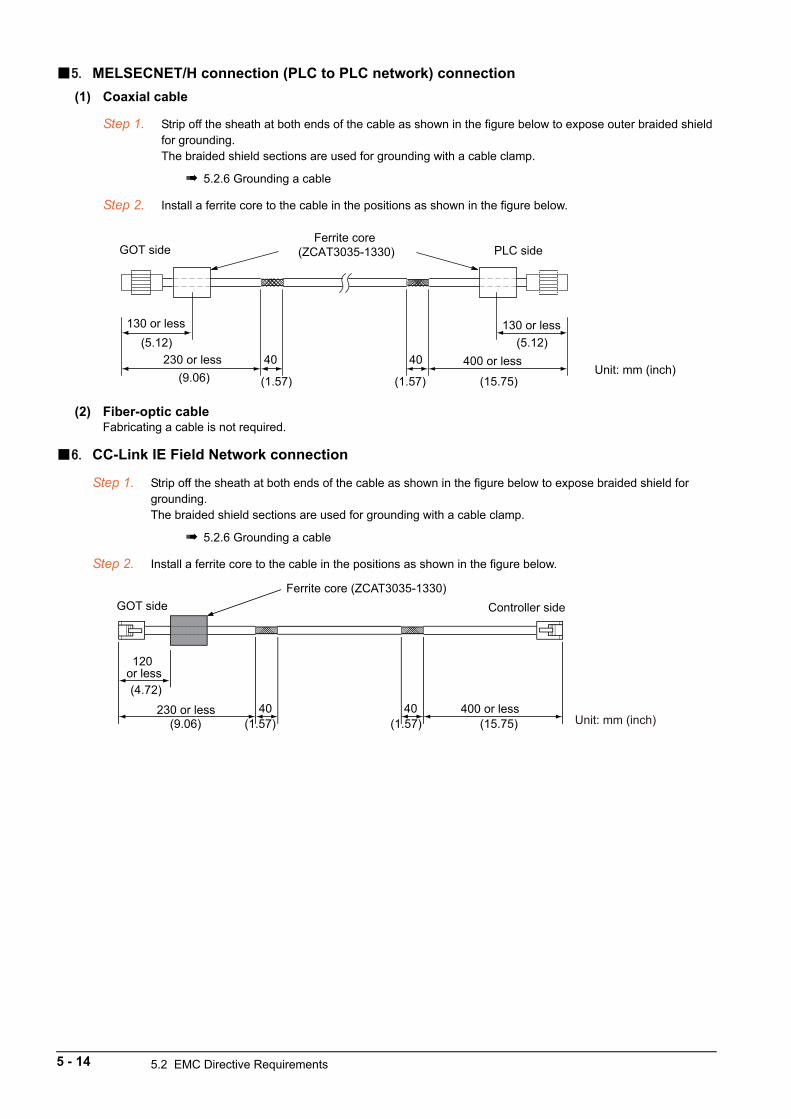
5. MELSECNET/H connection (PLC to PLC network) connection
(1) Coaxial cable
Step 1. Strip off the sheath at both ends of the cable as shown in the figure below to expose outer braided shield for grounding.The braided shield sections are used for grounding with a cable clamp.
5.2.6 Grounding a cable
Step 2. Install a ferrite core to the cable in the positions as shown in the figure below.
(2) Fiber-optic cableFabricating a cable is not required.
6. CC-Link IE Field Network connection
Step 1. Strip off the sheath at both ends of the cable as shown in the figure below to expose braided shield for grounding.The braided shield sections are used for grounding with a cable clamp.
5.2.6 Grounding a cable
Step 2. Install a ferrite core to the cable in the positions as shown in the figure below.
130 or less
GOT side PLC sideFerrite core
(ZCAT3035-1330)
230 or less 400 or less40 40Unit: mm (inch)
130 or less(5.12)
(9.06) (1.57)
(5.12)
(15.75)(1.57)
230 or less 40 40
120 or less
Controller sideFerrite core (ZCAT3035-1330)
GOT side
400 or lessUnit: mm (inch)
(4.72)
(9.06) (1.57) (15.75)(1.57)
5 - 14 5.2 EMC Directive Requirements
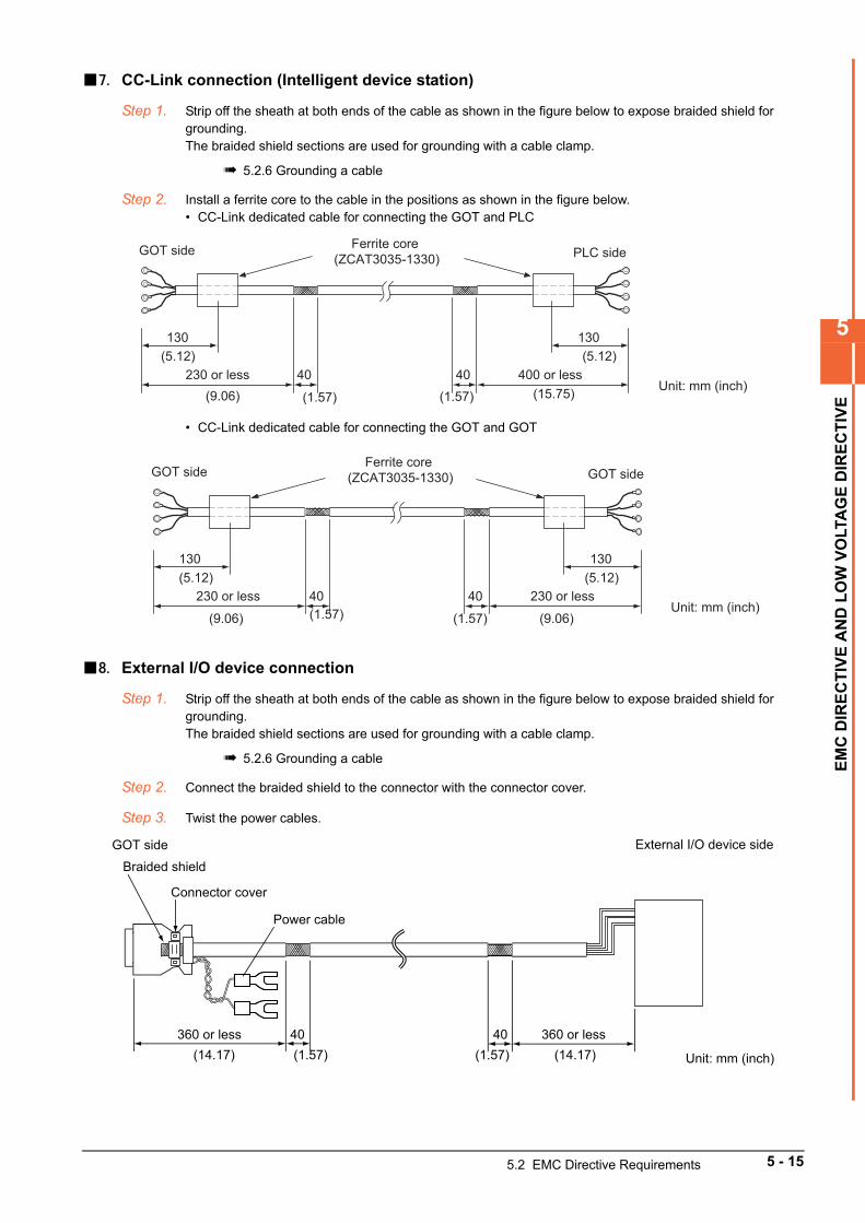
5
EM
C D
IRE
CT
IVE
AN
D L
OW
VO
LTA
GE
DIR
EC
TIV
E
7. CC-Link connection (Intelligent device station)
Step 1. Strip off the sheath at both ends of the cable as shown in the figure below to expose braided shield for grounding.The braided shield sections are used for grounding with a cable clamp.
5.2.6 Grounding a cable
Step 2. Install a ferrite core to the cable in the positions as shown in the figure below.• CC-Link dedicated cable for connecting the GOT and PLC
• CC-Link dedicated cable for connecting the GOT and GOT
8. External I/O device connection
Step 1. Strip off the sheath at both ends of the cable as shown in the figure below to expose braided shield for grounding.The braided shield sections are used for grounding with a cable clamp.
5.2.6 Grounding a cable
Step 2. Connect the braided shield to the connector with the connector cover.
Step 3. Twist the power cables.
130
GOT side PLC sideFerrite core
(ZCAT3035-1330)
230 or less 400 or less40 40Unit: mm (inch)
130(5.12)
(9.06) (1.57) (15.75)
(5.12)
(1.57)
130
GOT side GOT sideFerrite core
(ZCAT3035-1330)
230 or less 230 or less40 40Unit: mm (inch)
130(5.12)
(9.06) (1.57)
(5.12)
(9.06)(1.57)
Connector cover
Braided shieldGOT side
External I/O device side
360 or less 360 or less40 40
Unit: mm (inch)
Power cable
(14.17) (1.57) (14.17)(1.57)
5.2 EMC Directive Requirements 5 - 15
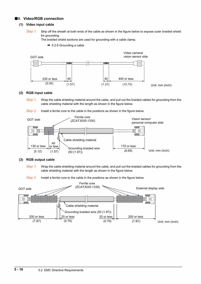
9. Video/RGB connection
(1) Video input cable
Step 1. Strip off the sheath at both ends of the cable as shown in the figure below to expose outer braided shield for grounding.The braided shield sections are used for grounding with a cable clamp.
5.2.6 Grounding a cable
(2) RGB input cable
Step 1. Wrap the cable shielding material around the cable, and pull out the braided cables for grounding from the cable shielding material with the length as shown in the figure below.
Step 2. Install a ferrite core to the cable in the positions as shown in the figure below.
(3) RGB output cable
Step 1. Wrap the cable shielding material around the cable, and pull out the braided cables for grounding from the cable shielding material with the length as shown in the figure below.
Step 2. Install a ferrite core to the cable in the positions as shown in the figure below.
(9.06) (1.57) (15.75)(1.57)
Video camera/vision sensor sideGOT side
Unit: mm (inch)
230 or less 40 40 400 or less
GOT side Vision sensor/personal computer side
40 or less130 or less
Unit: mm (inch)
Ferrite core (ZCAT3035-1330)
Grounding braided wire (50 (1.97))
Cable shielding material
170 or less
(5.12) (1.57) (6.69)
GOT side External display side
200 or less 200 or less20 or less 20 or less
Unit: mm (inch)
Ferrite core (ZCAT3035-1330)
Grounding braided wire (50 (1.97))
Cable shielding material
(7.87) (0.79) (0.79) (7.87)
5 - 16 5.2 EMC Directive Requirements
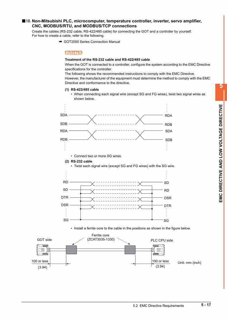
5
EM
C D
IRE
CT
IVE
AN
D L
OW
VO
LTA
GE
DIR
EC
TIV
E
10. Non-Mitsubishi PLC, microcomputer, temperature controller, inverter, servo amplifier, CNC, MODBUS/RTU, and MODBUS/TCP connectionsCreate the cables (RS-232 cable, RS-422/485 cable) for connecting the GOT and a controller by yourself.For how to create a cable, refer to the following.
GOT2000 Series Connection Manual
POINTPOINTPOINTTreatment of the RS-232 cable and RS-422/485 cable
When the GOT is connected to a controller, configure the system according to the EMC Directive specifications for the controller.The following shows the recommended instructions to comply with the EMC Directive.However, the manufacturer of the equipment must determine the method to comply with the EMC Directive and conformance to the directive.
(1) RS-422/485 cable• When connecting each signal wire (except SG and FG wires), twist two signal wires as
shown below.
• Connect two or more SG wires.
(2) RS-232 cable• Twist each signal wire (except SG and FG wires) with the SG wire.
• Install a ferrite core to the cable in the positions as shown in the figure below.
SDA RDA
RDBSDB
RDA
RDB
SDA
SDB
RD
RDSD
SD
DTR
DTR
DSR
DSR
SG SG
100 or less
Ferrite core (ZCAT3035-1330)
100 or less
GOT side PLC CPU side
Unit: mm (inch)(3.94) (3.94)
5.2 EMC Directive Requirements 5 - 17
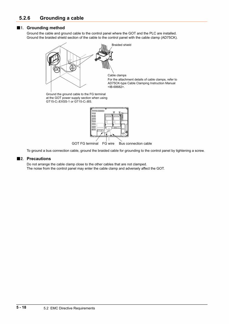
5.2.6 Grounding a cable
1. Grounding methodGround the cable and ground cable to the control panel where the GOT and the PLC are installed.Ground the braided shield section of the cable to the control panel with the cable clamp (AD75CK).
To ground a bus connection cable, ground the braided cable for grounding to the control panel by tightening a screw.
2. PrecautionsDo not arrange the cable clamp close to the other cables that are not clamped.The noise from the control panel may enter the cable clamp and adversely affect the GOT.
Braided shield
Cable clampsFor the attachment details of cable clamps, refer to AD75CK-type Cable Clamping Instruction Manual <IB-68682>.
Ground the ground cable to the FG terminal at the GOT power supply section when using GT15-CEXSS-1 or GT15-CBS.
GOT FG terminal FG wire Bus connection cable
5 - 18 5.2 EMC Directive Requirements
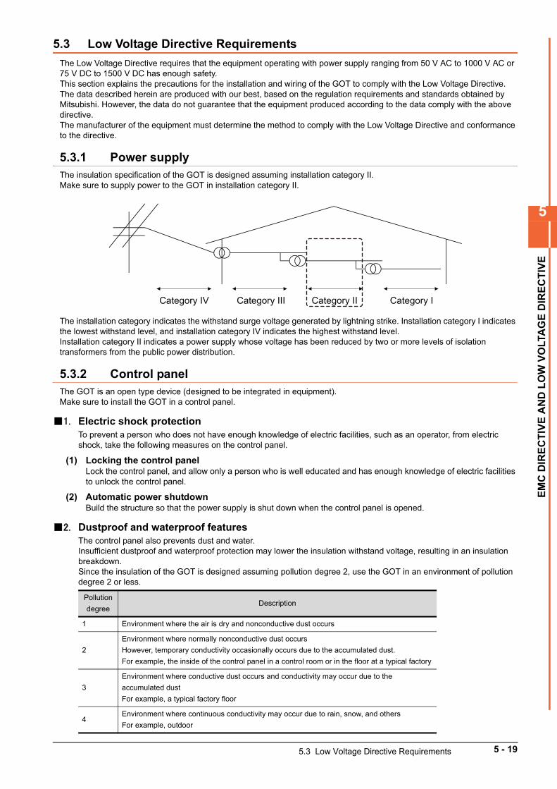
5
EM
C D
IRE
CT
IVE
AN
D L
OW
VO
LTA
GE
DIR
EC
TIV
E
5.3 Low Voltage Directive Requirements
The Low Voltage Directive requires that the equipment operating with power supply ranging from 50 V AC to 1000 V AC or 75 V DC to 1500 V DC has enough safety.This section explains the precautions for the installation and wiring of the GOT to comply with the Low Voltage Directive.The data described herein are produced with our best, based on the regulation requirements and standards obtained by Mitsubishi. However, the data do not guarantee that the equipment produced according to the data comply with the above directive.The manufacturer of the equipment must determine the method to comply with the Low Voltage Directive and conformance to the directive.
5.3.1 Power supplyThe insulation specification of the GOT is designed assuming installation category II.Make sure to supply power to the GOT in installation category II.
The installation category indicates the withstand surge voltage generated by lightning strike. Installation category I indicates the lowest withstand level, and installation category IV indicates the highest withstand level.Installation category II indicates a power supply whose voltage has been reduced by two or more levels of isolation transformers from the public power distribution.
5.3.2 Control panelThe GOT is an open type device (designed to be integrated in equipment).Make sure to install the GOT in a control panel.
1. Electric shock protectionTo prevent a person who does not have enough knowledge of electric facilities, such as an operator, from electric shock, take the following measures on the control panel.
(1) Locking the control panelLock the control panel, and allow only a person who is well educated and has enough knowledge of electric facilities to unlock the control panel.
(2) Automatic power shutdownBuild the structure so that the power supply is shut down when the control panel is opened.
2. Dustproof and waterproof featuresThe control panel also prevents dust and water.Insufficient dustproof and waterproof protection may lower the insulation withstand voltage, resulting in an insulation breakdown.Since the insulation of the GOT is designed assuming pollution degree 2, use the GOT in an environment of pollution degree 2 or less.
Pollution
degreeDescription
1 Environment where the air is dry and nonconductive dust occurs
2
Environment where normally nonconductive dust occurs
However, temporary conductivity occasionally occurs due to the accumulated dust.
For example, the inside of the control panel in a control room or in the floor at a typical factory
3
Environment where conductive dust occurs and conductivity may occur due to the
accumulated dust
For example, a typical factory floor
4Environment where continuous conductivity may occur due to rain, snow, and others
For example, outdoor
Category IV Category III Category II Category I
5.3 Low Voltage Directive Requirements 5 - 19
5.3.3 GroundingThe GOT has the following ground terminals.The ground terminals must be grounded in use.Ground the GOT to ensure the safety and to comply with the EMC Directive.
Functional grounding : The functional ground terminal improves noise resistance.
5.3.4 External wiring
1. External controllersIf an external device connected to the GOT has a hazardous voltage circuit, the interface circuit to the GOT must have a reinforced insulation.
2. Reinforced insulationThe reinforced insulation indicates the insulation with the following withstand voltage.
Reinforced insulation withstand voltage (Source: Installation Category II of IEC664)
Rated voltage of hazardous voltage area Withstand surge voltage (1.2/50 µs)
150 V AC or less 2500V
300 V AC or less 4000V
5 - 20 5.3 Low Voltage Directive Requirements
6
INS
TAL
LA
TIO
N A
ND
RE
MO
VA
L
6. INSTALLATION AND REMOVAL
6.1 Installation Precautions . . . . . . . . . . . . . . . . . . . . . . . . . . . . . . . . 6 - 2
6.2 Panel Cut Dimensions . . . . . . . . . . . . . . . . . . . . . . . . . . . . . . . . . 6 - 2
6.3 Installation Position . . . . . . . . . . . . . . . . . . . . . . . . . . . . . . . . . . . 6 - 3
6.4 Control Panel Inside Temperature and GOT Installation Angle 6 - 6
6.5 Installing and Removing the GOT . . . . . . . . . . . . . . . . . . . . . . . . 6 - 6
6.6 Installing and Removing the Extension Unit . . . . . . . . . . . . . . . 6 - 8
6.7 Installing and Removing the Battery . . . . . . . . . . . . . . . . . . . . 6 - 11
6.8 Installing and Removing the SD Card. . . . . . . . . . . . . . . . . . . . 6 - 14
6.9 Installing and Removing the USB Devices. . . . . . . . . . . . . . . . 6 - 16
6.10 Installing and Removing the USB cable . . . . . . . . . . . . . . . . . . 6 - 17
6 - 1
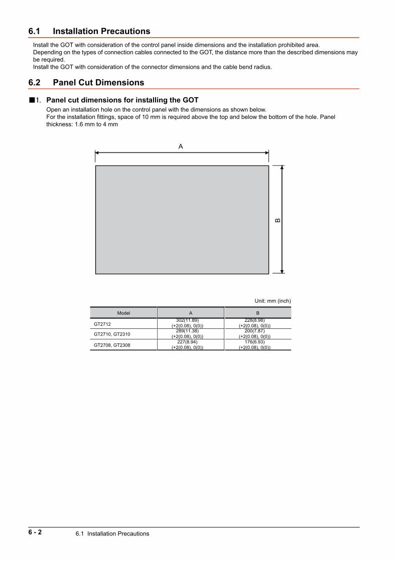
6.1 Installation Precautions
Install the GOT with consideration of the control panel inside dimensions and the installation prohibited area.Depending on the types of connection cables connected to the GOT, the distance more than the described dimensions may be required.Install the GOT with consideration of the connector dimensions and the cable bend radius.
6.2 Panel Cut Dimensions
1. Panel cut dimensions for installing the GOTOpen an installation hole on the control panel with the dimensions as shown below.For the installation fittings, space of 10 mm is required above the top and below the bottom of the hole. Panel thickness: 1.6 mm to 4 mm
A
Model
GT2712
GT2710, GT2310
GT2708, GT2308
A302(11.89)
(+2(0.08), 0(0))289(11.38)
(+2(0.08), 0(0))227(8.94)
(+2(0.08), 0(0))
B
Unit: mm (inch)
228(8.98)(+2(0.08), 0(0))
200(7.87)(+2(0.08), 0(0))
176(6.93)(+2(0.08), 0(0))
B
6 - 2 6.1 Installation Precautions
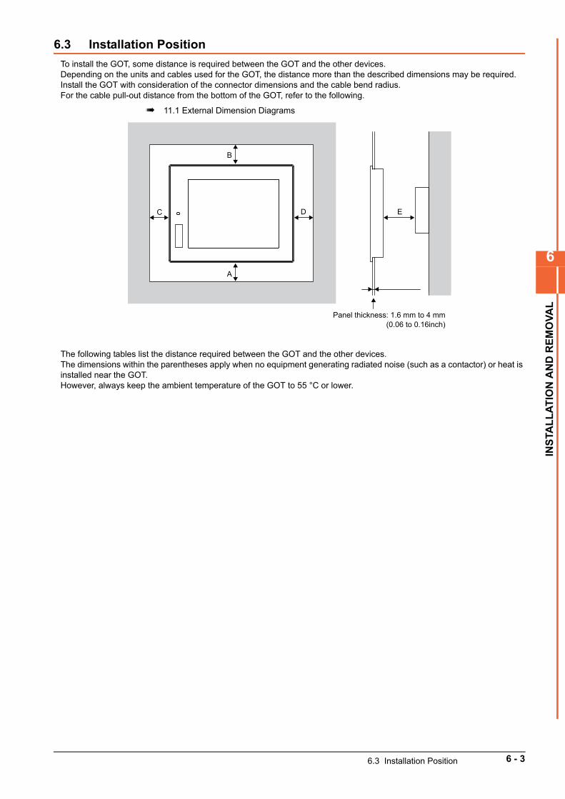
6
INS
TAL
LA
TIO
N A
ND
RE
MO
VA
L
6.3 Installation Position
To install the GOT, some distance is required between the GOT and the other devices.Depending on the units and cables used for the GOT, the distance more than the described dimensions may be required.Install the GOT with consideration of the connector dimensions and the cable bend radius.For the cable pull-out distance from the bottom of the GOT, refer to the following.
11.1 External Dimension Diagrams
The following tables list the distance required between the GOT and the other devices.The dimensions within the parentheses apply when no equipment generating radiated noise (such as a contactor) or heat is installed near the GOT.However, always keep the ambient temperature of the GOT to 55 °C or lower.
B
D E
A
C
Panel thickness: 1.6 mm to 4 mm(0.06 to 0.16inch)
6.3 Installation Position 6 - 3
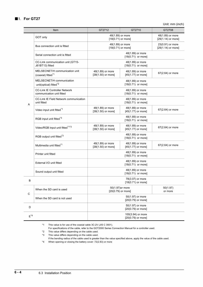
1. For GT27Unit: mm (inch)
*1 This value is for use of the coaxial cable 3C-2V (JIS C 3501).
For specifications of the cable, refer to the GOT2000 Series Connection Manual for a controller used.
*2 This value differs depending on the cable used.
*3 This value differs depending on the cable used.
If the bending radius of the cable used is greater than the value specified above, apply the value of the cable used.
*4 When opening or closing the battery cover: 72(2.83) or more
Item GT2712 GT2710 GT2708
A
GOT only48(1.89) or more
[18(0.71) or more]48(1.89) or more
[29(1.14) or more]
Bus connection unit is fitted48(1.89) or more
[18(0.71) or more]23(0.91) or more
[29(1.14) or more]
Serial connection unit is fitted48(1.89) or more
[18(0.71) or more]
CC-Link communication unit (GT15-J61BT13) fitted
48(1.89) or more[18(0.71) or more]
MELSECNET/H communication unit
(coaxial) fitted*148(1.89) or more
[38(1.50) or more]48(1.89) or more
[45(1.77) or more]67(2.64) or more
MELSECNET/H communication
unit(optical) fitted*248(1.89) or more
[18(0.71) or more]
CC-Link IE Controller Networkcommunication unit fitted
48(1.89) or more[18(0.71) or more]
CC-Link IE Field Network communication unit fitted
48(1.89) or more[18(0.71) or more]
Video input unit fitted*1 48(1.89) or more[38(1.50) or more]
48(1.89) or more[45(1.77) or more]
67(2.64) or more
RGB input unit fitted*3 48(1.89) or more[18(0.71) or more]
Video/RGB input unit fitted*1*3 48(1.89) or more[38(1.50) or more]
48(1.89) or more[45(1.77) or more]
67(2.64) or more
RGB output unit fitted*3 48(1.89) or more[18(0.71) or more]
Multimedia unit fitted*1 48(1.89) or more[38(1.50) or more]
48(1.89) or more[45(1.77) or more]
67(2.64) or more
Printer unit fitted48(1.89) or more
[18(0.71) or more]
External I/O unit fitted48(1.89) or more
[18(0.71) or more]
Sound output unit fitted48(1.89) or more
[18(0.71) or more]
B78(3.07) or more
[18(0.71) or more]
C
When the SD card is used50(1.97)or more
[20(0.79) or more]50(1.97)or more
When the SD card is not used50(1.97) or more
[20(0.79) or more]
D50(1.97) or more
[20(0.79) or more]
E*4 100(3.94) or more[20(0.79) or more]
6 - 4 6.3 Installation Position
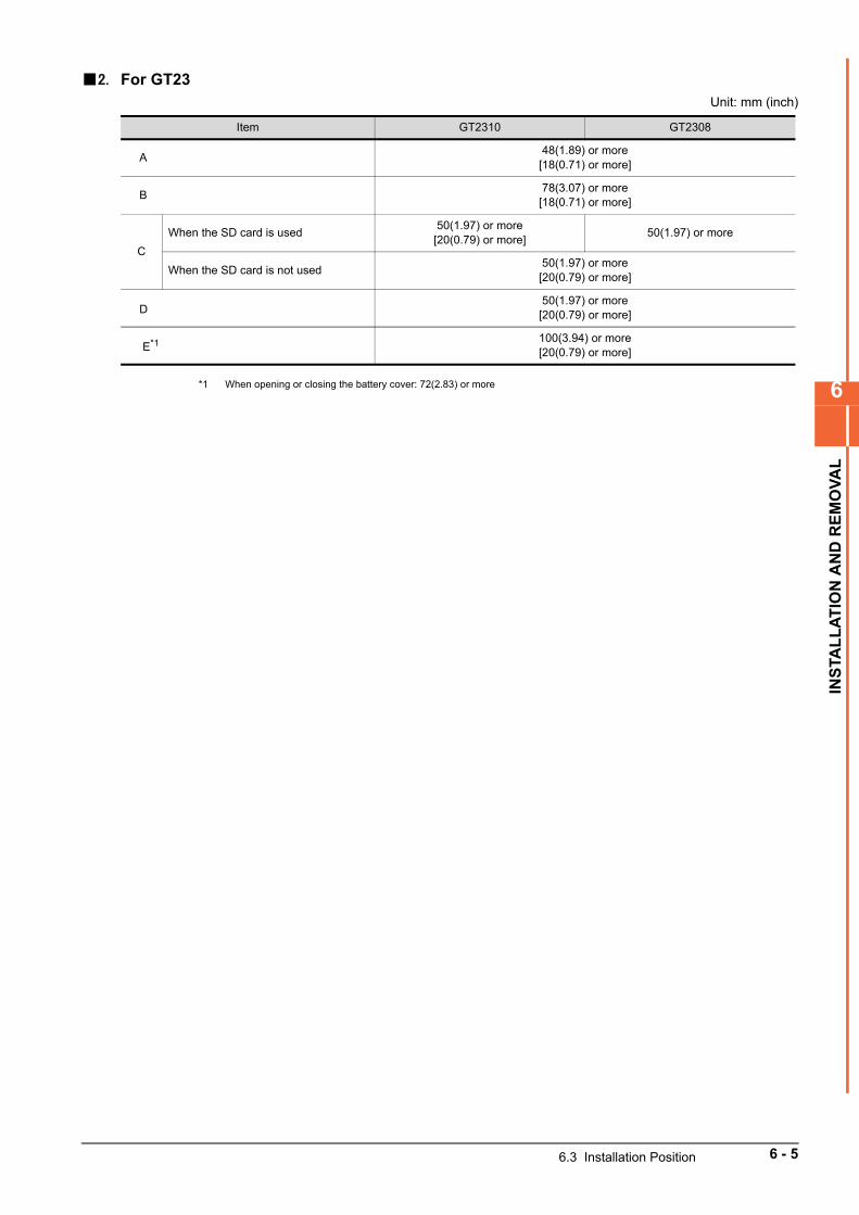
6
INS
TAL
LA
TIO
N A
ND
RE
MO
VA
L
2. For GT23Unit: mm (inch)
*1 When opening or closing the battery cover: 72(2.83) or more
Item GT2310 GT2308
A48(1.89) or more
[18(0.71) or more]
B78(3.07) or more
[18(0.71) or more]
C
When the SD card is used50(1.97) or more
[20(0.79) or more]50(1.97) or more
When the SD card is not used50(1.97) or more
[20(0.79) or more]
D50(1.97) or more
[20(0.79) or more]
E*1 100(3.94) or more[20(0.79) or more]
6.3 Installation Position 6 - 5
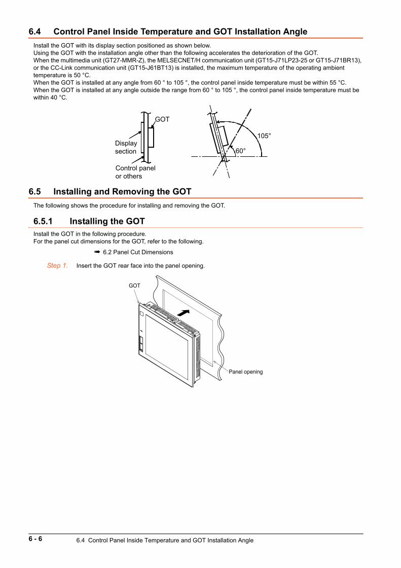
6.4 Control Panel Inside Temperature and GOT Installation Angle
Install the GOT with its display section positioned as shown below.Using the GOT with the installation angle other than the following accelerates the deterioration of the GOT.When the multimedia unit (GT27-MMR-Z), the MELSECNET/H communication unit (GT15-J71LP23-25 or GT15-J71BR13), or the CC-Link communication unit (GT15-J61BT13) is installed, the maximum temperature of the operating ambient temperature is 50 °C.When the GOT is installed at any angle from 60 ° to 105 °, the control panel inside temperature must be within 55 °C.When the GOT is installed at any angle outside the range from 60 ° to 105 °, the control panel inside temperature must be within 40 °C.
6.5 Installing and Removing the GOT
The following shows the procedure for installing and removing the GOT.
6.5.1 Installing the GOTInstall the GOT in the following procedure.For the panel cut dimensions for the GOT, refer to the following.
6.2 Panel Cut Dimensions
Step 1. Insert the GOT rear face into the panel opening.
GOT
Display section
Control panel or others
105°
60°
Panel opening
GOT
6 - 6 6.4 Control Panel Inside Temperature and GOT Installation Angle
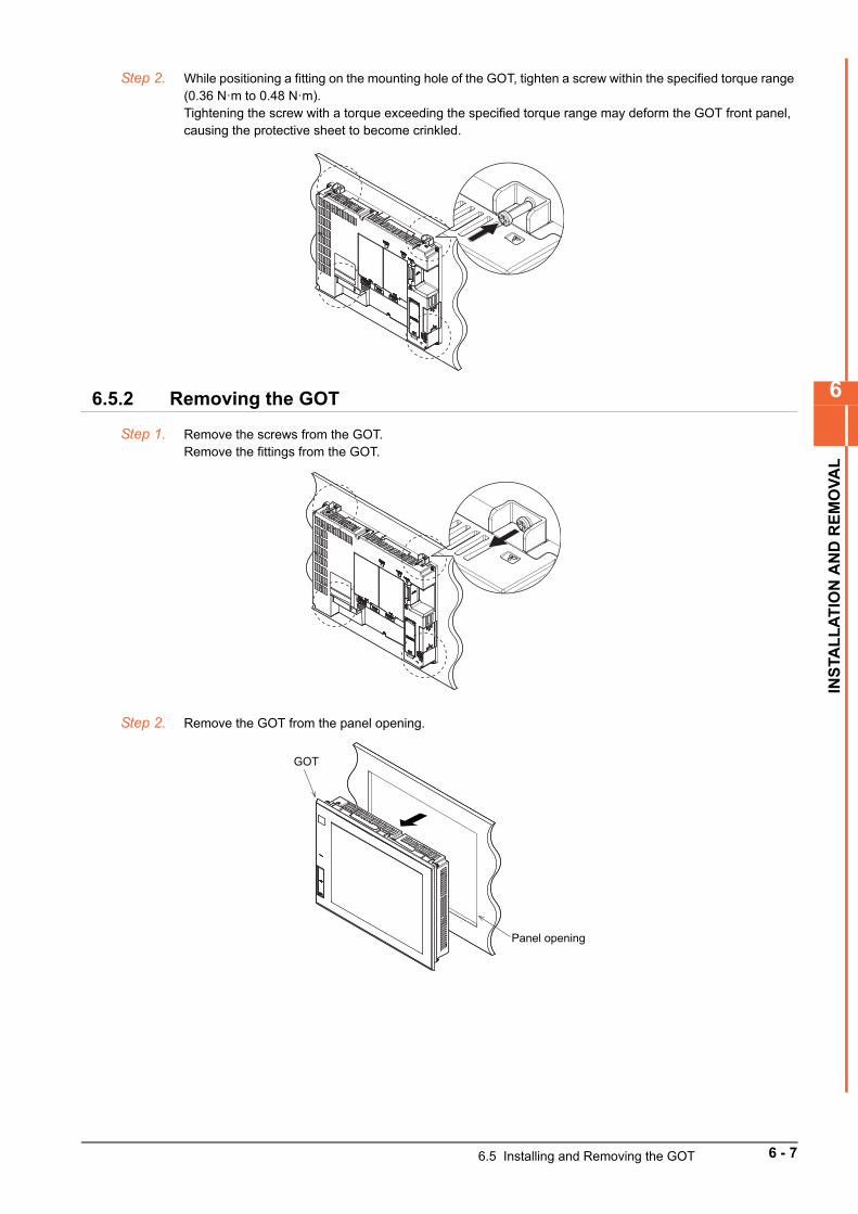
6
INS
TAL
LA
TIO
N A
ND
RE
MO
VA
L
Step 2. While positioning a fitting on the mounting hole of the GOT, tighten a screw within the specified torque range (0.36 N·m to 0.48 N·m).Tightening the screw with a torque exceeding the specified torque range may deform the GOT front panel, causing the protective sheet to become crinkled.
6.5.2 Removing the GOT
Step 1. Remove the screws from the GOT.Remove the fittings from the GOT.
Step 2. Remove the GOT from the panel opening.
Panel opening
GOT
6.5 Installing and Removing the GOT 6 - 7
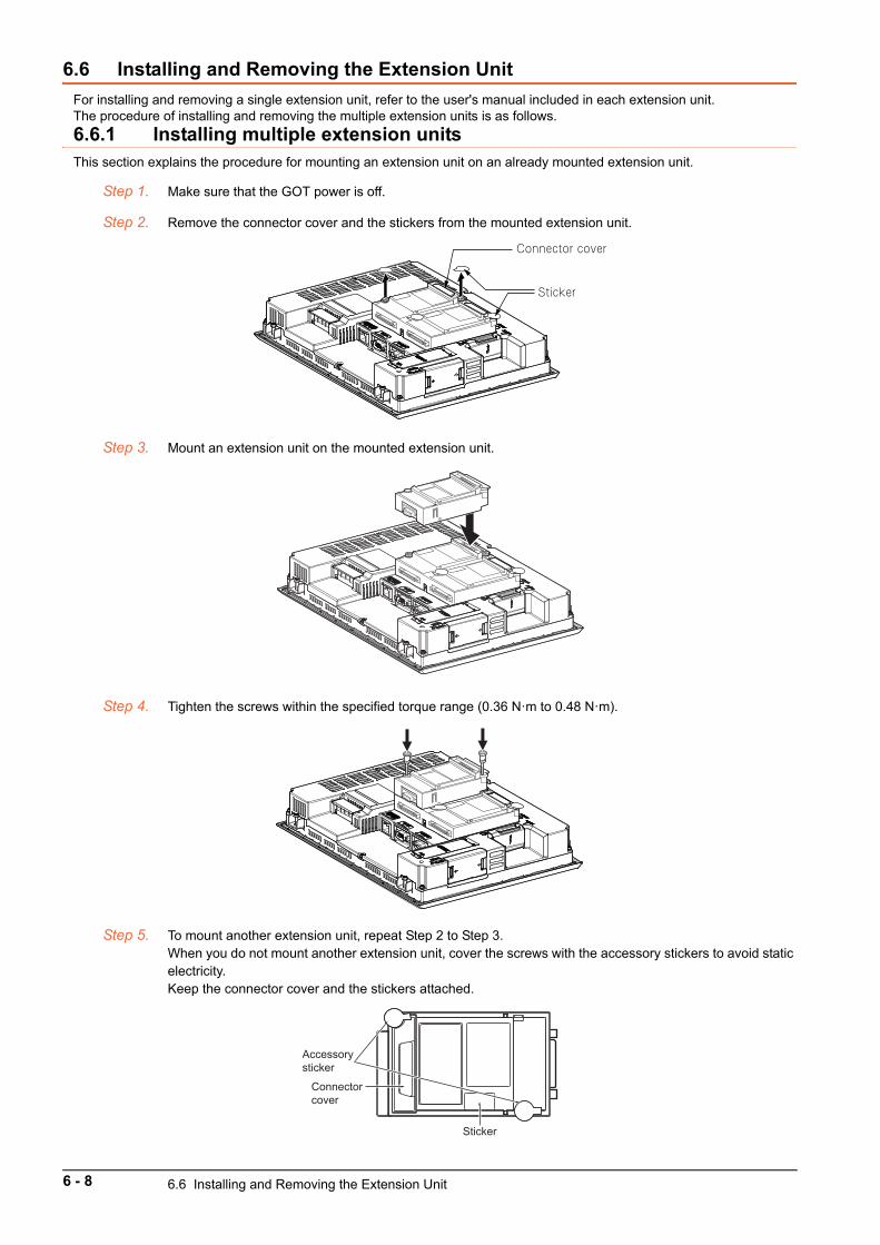
6.6 Installing and Removing the Extension Unit
For installing and removing a single extension unit, refer to the user's manual included in each extension unit.The procedure of installing and removing the multiple extension units is as follows.
6.6.1 Installing multiple extension unitsThis section explains the procedure for mounting an extension unit on an already mounted extension unit.
Step 1. Make sure that the GOT power is off.
Step 2. Remove the connector cover and the stickers from the mounted extension unit.
Step 3. Mount an extension unit on the mounted extension unit.
Step 4. Tighten the screws within the specified torque range (0.36 N·m to 0.48 N·m).
Step 5. To mount another extension unit, repeat Step 2 to Step 3.When you do not mount another extension unit, cover the screws with the accessory stickers to avoid static electricity.Keep the connector cover and the stickers attached.
Connector cover
Sticker
Sticker
Accessory sticker
Connector cover
6 - 8 6.6 Installing and Removing the Extension Unit
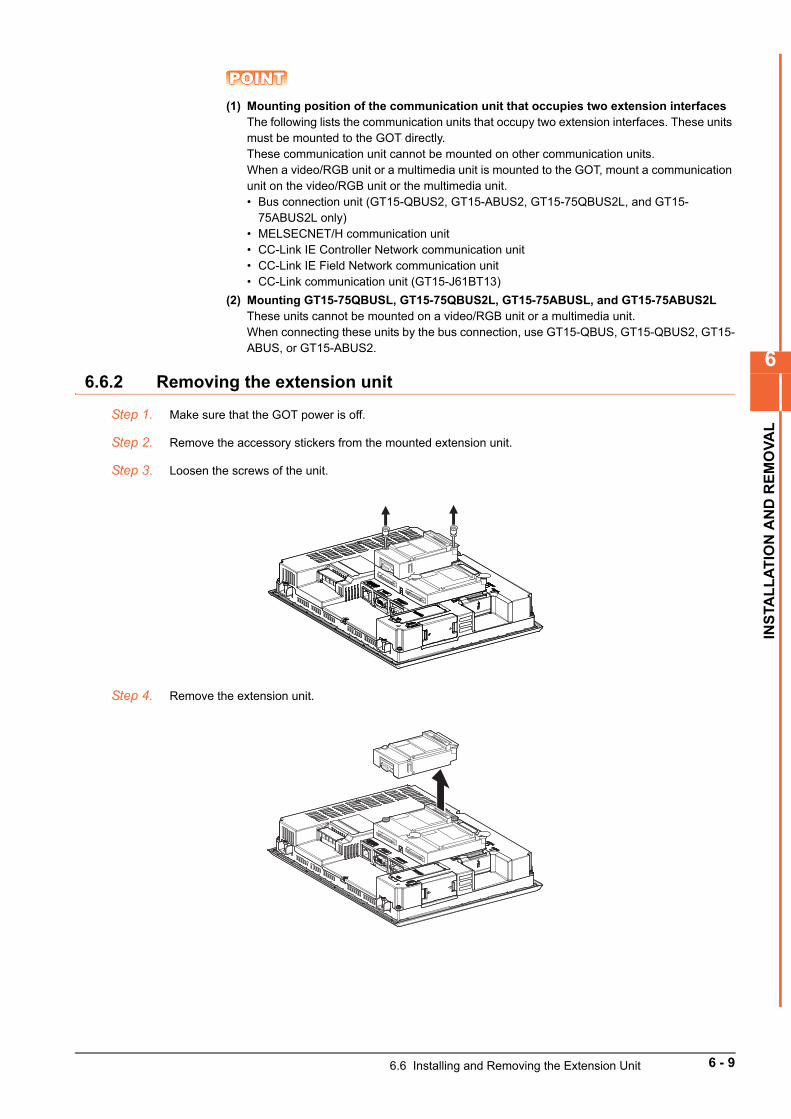
6
INS
TAL
LA
TIO
N A
ND
RE
MO
VA
L
POINTPOINTPOINT(1) Mounting position of the communication unit that occupies two extension interfaces
The following lists the communication units that occupy two extension interfaces. These units must be mounted to the GOT directly.These communication unit cannot be mounted on other communication units.When a video/RGB unit or a multimedia unit is mounted to the GOT, mount a communication unit on the video/RGB unit or the multimedia unit.• Bus connection unit (GT15-QBUS2, GT15-ABUS2, GT15-75QBUS2L, and GT15-
75ABUS2L only)• MELSECNET/H communication unit• CC-Link IE Controller Network communication unit• CC-Link IE Field Network communication unit• CC-Link communication unit (GT15-J61BT13)
(2) Mounting GT15-75QBUSL, GT15-75QBUS2L, GT15-75ABUSL, and GT15-75ABUS2LThese units cannot be mounted on a video/RGB unit or a multimedia unit.When connecting these units by the bus connection, use GT15-QBUS, GT15-QBUS2, GT15-ABUS, or GT15-ABUS2.
6.6.2 Removing the extension unit
Step 1. Make sure that the GOT power is off.
Step 2. Remove the accessory stickers from the mounted extension unit.
Step 3. Loosen the screws of the unit.
Step 4. Remove the extension unit.
6.6 Installing and Removing the Extension Unit 6 - 9
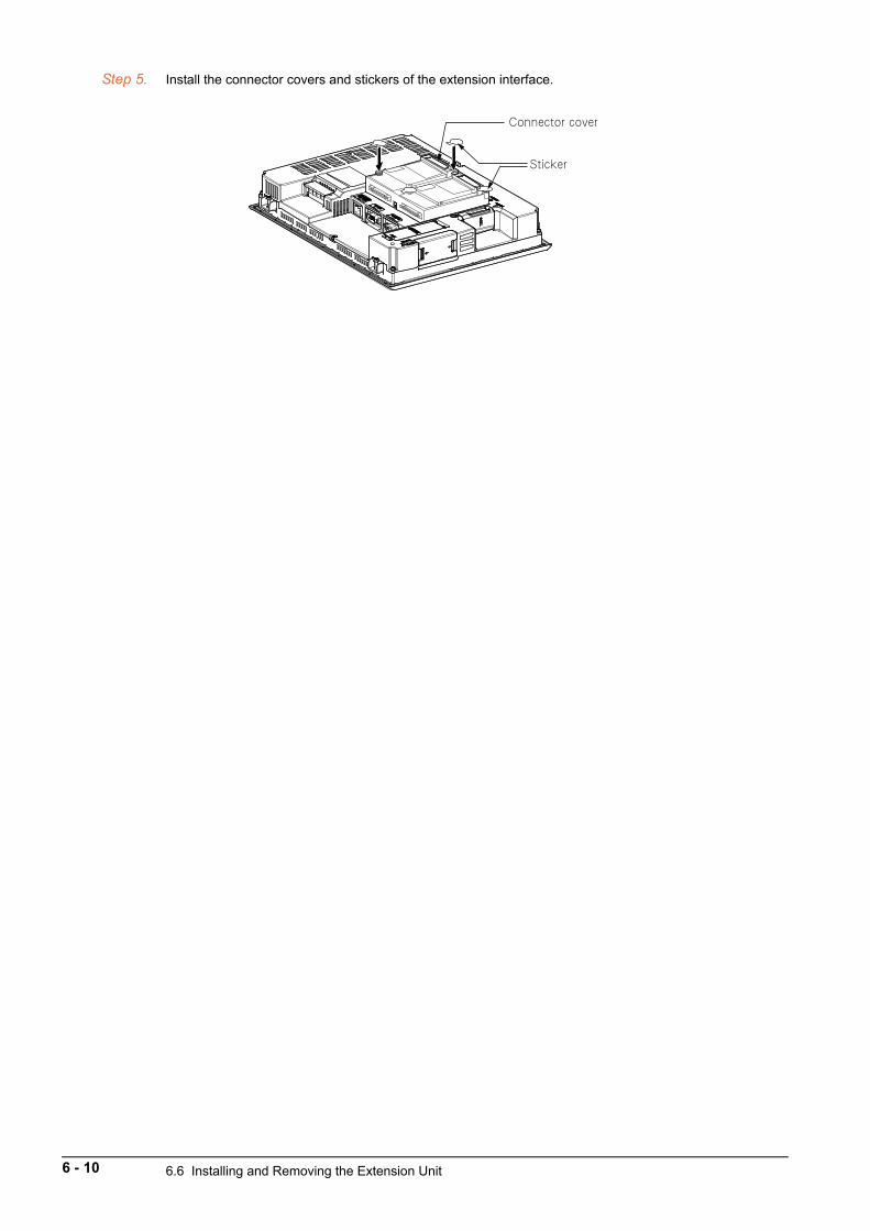
Step 5. Install the connector covers and stickers of the extension interface.
Connector cover
Sticker
6 - 10 6.6 Installing and Removing the Extension Unit

6
INS
TAL
LA
TIO
N A
ND
RE
MO
VA
L
6.7 Installing and Removing the Battery
Install a battery to the GOT before the first startup.The following shows the procedure for installing and removing a battery.(Described with the GOT rear face facing up.)
POINTPOINTPOINT(1) Battery for GT27
GT27 has a battery in the battery cover as default. Before using GT27, connect the battery connector to the GOT connector.
(2) Battery for GT23Batteries for GT23 (GT11-50BAT) are sold separately. Purchase a battery before using GT23, mount it to the GOT, and connect the GOT connector to battery connector.
(3) battery replacement timeTo replace the battery, leave the GOT on for more than 10 minutes before replacing the battery.Replace the battery within 5 minutes.(As for GT23, replace the battery within 30 seconds.)
6.7.1 Installing the battery
Step 1. Make sure that the GOT power is off.
Step 2. Install the battery to the GOT rear face.Open the battery cover as shown below.
Step 3. To replace the battery, remove the old battery, and then disconnect the connector.
Step 4. Insert the connector of a new battery.Make sure to insert the connector in the correct direction.
Battery cover Battery cover
Example) GT2712 Example) GT2708 Example) GT2310
SD card cover
6.7 Installing and Removing the Battery 6 - 11
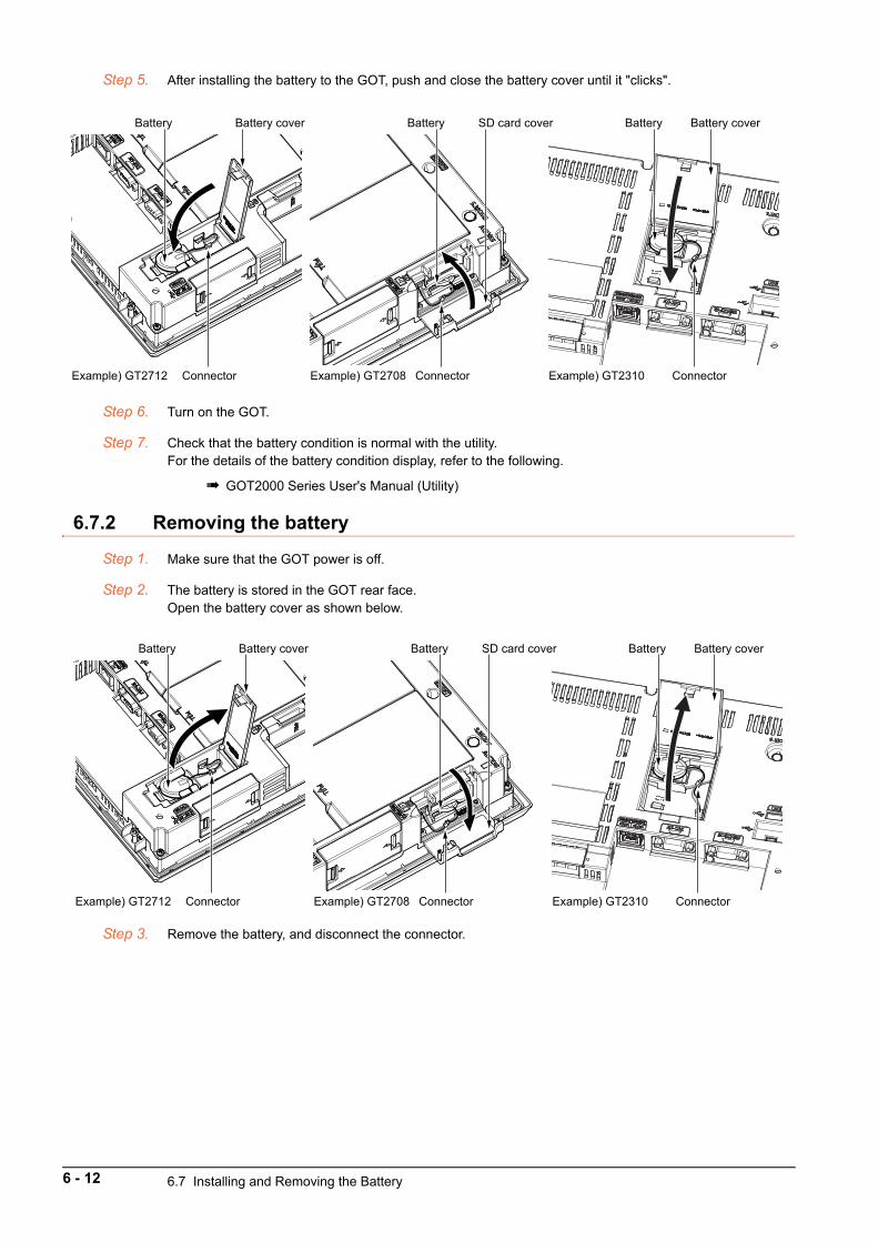
Step 5. After installing the battery to the GOT, push and close the battery cover until it "clicks".
Step 6. Turn on the GOT.
Step 7. Check that the battery condition is normal with the utility.For the details of the battery condition display, refer to the following.
GOT2000 Series User's Manual (Utility)
6.7.2 Removing the battery
Step 1. Make sure that the GOT power is off.
Step 2. The battery is stored in the GOT rear face.Open the battery cover as shown below.
Step 3. Remove the battery, and disconnect the connector.
Example) GT2712 Example) GT2708 Example) GT2310
Battery cover
Connector
Battery SD card cover
Connector
Battery Battery cover
Connector
Battery
Example) GT2712 Example) GT2708 Example) GT2310
Battery cover
Connector
Battery SD card cover
Connector
Battery Battery cover
Connector
Battery
6 - 12 6.7 Installing and Removing the Battery
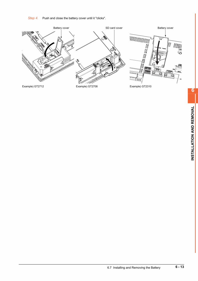
6
INS
TAL
LA
TIO
N A
ND
RE
MO
VA
L
Step 4. Push and close the battery cover until it "clicks".
Battery cover Battery cover
Example) GT2712 Example) GT2708 Example) GT2310
SD card cover
6.7 Installing and Removing the Battery 6 - 13
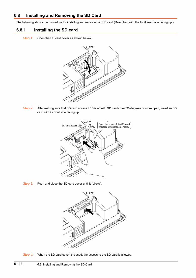
6.8 Installing and Removing the SD Card
The following shows the procedure for installing and removing an SD card.(Described with the GOT rear face facing up.)
6.8.1 Installing the SD card
Step 1. Open the SD card cover as shown below.
Step 2. After making sure that SD card access LED is off with SD card cover 90 degrees or more open, insert an SD card with its front side facing up.
Step 3. Push and close the SD card cover until it "clicks".
Step 4. When the SD card cover is closed, the access to the SD card is allowed.
Open the cover of the SD card interface 90 degrees or more.SD card access LED
6 - 14 6.8 Installing and Removing the SD Card
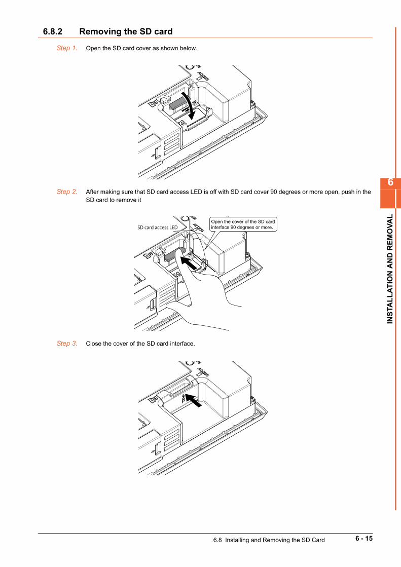
6
INS
TAL
LA
TIO
N A
ND
RE
MO
VA
L
6.8.2 Removing the SD card
Step 1. Open the SD card cover as shown below.
Step 2. After making sure that SD card access LED is off with SD card cover 90 degrees or more open, push in the SD card to remove it
Step 3. Close the cover of the SD card interface.
Open the cover of the SD card interface 90 degrees or more.SD card access LED
6.8 Installing and Removing the SD Card 6 - 15
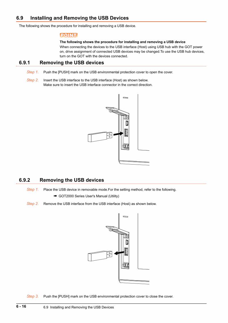
6.9 Installing and Removing the USB Devices
The following shows the procedure for installing and removing a USB device.
POINTPOINTPOINTThe following shows the procedure for installing and removing a USB device
When connecting the devices to the USB interface (Host) using USB hub with the GOT power on, drive assignment of connected USB devices may be changed.To use the USB hub devices, turn on the GOT with the devices connected.
6.9.1 Removing the USB devices
Step 1. Push the [PUSH] mark on the USB environmental protection cover to open the cover.
Step 2. Insert the USB interface to the USB interface (Host) as shown below.Make sure to insert the USB interface connector in the correct direction.
6.9.2 Removing the USB devices
Step 1. Place the USB device in removable mode.For the setting method, refer to the following.
GOT2000 Series User's Manual (Utility)
Step 2. Remove the USB interface from the USB interface (Host) as shown below.
Step 3. Push the [PUSH] mark on the USB environmental protection cover to close the cover.
6 - 16 6.9 Installing and Removing the USB Devices
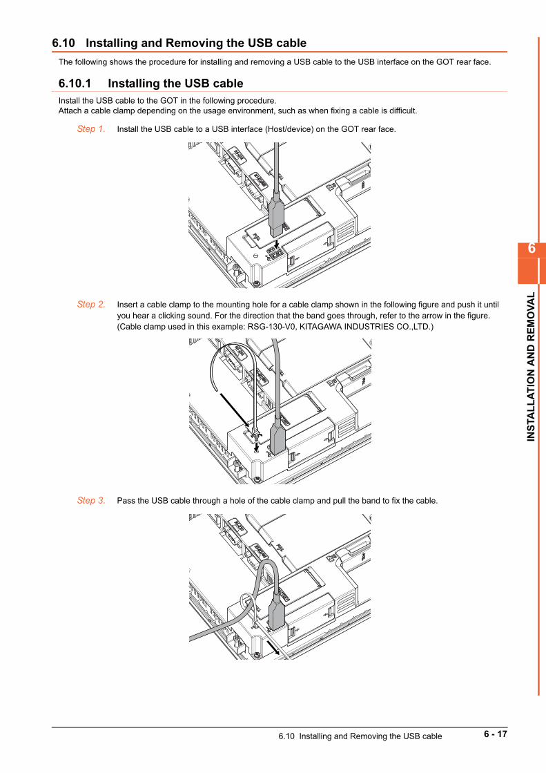
6
INS
TAL
LA
TIO
N A
ND
RE
MO
VA
L
6.10 Installing and Removing the USB cable
The following shows the procedure for installing and removing a USB cable to the USB interface on the GOT rear face.
6.10.1 Installing the USB cableInstall the USB cable to the GOT in the following procedure.Attach a cable clamp depending on the usage environment, such as when fixing a cable is difficult.
Step 1. Install the USB cable to a USB interface (Host/device) on the GOT rear face.
Step 2. Insert a cable clamp to the mounting hole for a cable clamp shown in the following figure and push it until you hear a clicking sound. For the direction that the band goes through, refer to the arrow in the figure.(Cable clamp used in this example: RSG-130-V0, KITAGAWA INDUSTRIES CO.,LTD.)
Step 3. Pass the USB cable through a hole of the cable clamp and pull the band to fix the cable.
6.10 Installing and Removing the USB cable 6 - 17
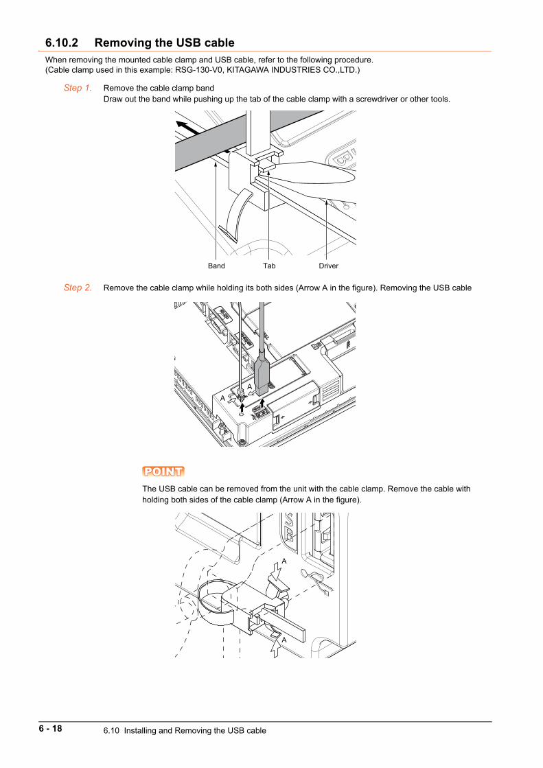
6.10.2 Removing the USB cableWhen removing the mounted cable clamp and USB cable, refer to the following procedure.(Cable clamp used in this example: RSG-130-V0, KITAGAWA INDUSTRIES CO.,LTD.)
Step 1. Remove the cable clamp bandDraw out the band while pushing up the tab of the cable clamp with a screwdriver or other tools.
Step 2. Remove the cable clamp while holding its both sides (Arrow A in the figure). Removing the USB cable
POINTPOINTPOINTThe USB cable can be removed from the unit with the cable clamp. Remove the cable with holding both sides of the cable clamp (Arrow A in the figure).
TabBand Driver
AA
A
A
6 - 18 6.10 Installing and Removing the USB cable

7
WIR
NG
OF
PO
WE
R S
UP
PLY
SE
CT
ION
7. WIRNG OF POWER SUPPLY SECTION
7.1 Wiring of External Power Supply . . . . . . . . . . . . . . . . . . . . . . . . 7 - 2
7.2 Power Supply Wiring to the GOT . . . . . . . . . . . . . . . . . . . . . . . . 7 - 3
7.3 Grounding . . . . . . . . . . . . . . . . . . . . . . . . . . . . . . . . . . . . . . . . . . . 7 - 4
7.4 Wiring Inside and Outside the Control Panel. . . . . . . . . . . . . . . 7 - 7
7.5 Attaching a Surge Suppressor to Control Equipment . . . . . . . 7 - 8
7.6 Grounding the Extension Unit. . . . . . . . . . . . . . . . . . . . . . . . . . . 7 - 9
7 - 1
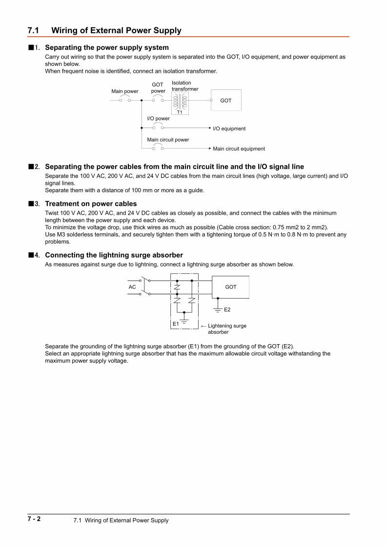
7.1 Wiring of External Power Supply
1. Separating the power supply systemCarry out wiring so that the power supply system is separated into the GOT, I/O equipment, and power equipment as shown below.When frequent noise is identified, connect an isolation transformer.
2. Separating the power cables from the main circuit line and the I/O signal lineSeparate the 100 V AC, 200 V AC, and 24 V DC cables from the main circuit lines (high voltage, large current) and I/O signal lines.Separate them with a distance of 100 mm or more as a guide.
3. Treatment on power cablesTwist 100 V AC, 200 V AC, and 24 V DC cables as closely as possible, and connect the cables with the minimum length between the power supply and each device.To minimize the voltage drop, use thick wires as much as possible (Cable cross section: 0.75 mm2 to 2 mm2).Use M3 solderless terminals, and securely tighten them with a tightening torque of 0.5 N·m to 0.8 N·m to prevent any problems.
4. Connecting the lightning surge absorberAs measures against surge due to lightning, connect a lightning surge absorber as shown below.
Separate the grounding of the lightning surge absorber (E1) from the grounding of the GOT (E2).Select an appropriate lightning surge absorber that has the maximum allowable circuit voltage withstanding the maximum power supply voltage.
GOT
I/O equipment
Main circuit equipment
GOT power
Isolation transformerMain power
I/O power
Main circuit power
T1
AC
E1
E2
←
GOT
Lightening surge absorber
7 - 2 7.1 Wiring of External Power Supply
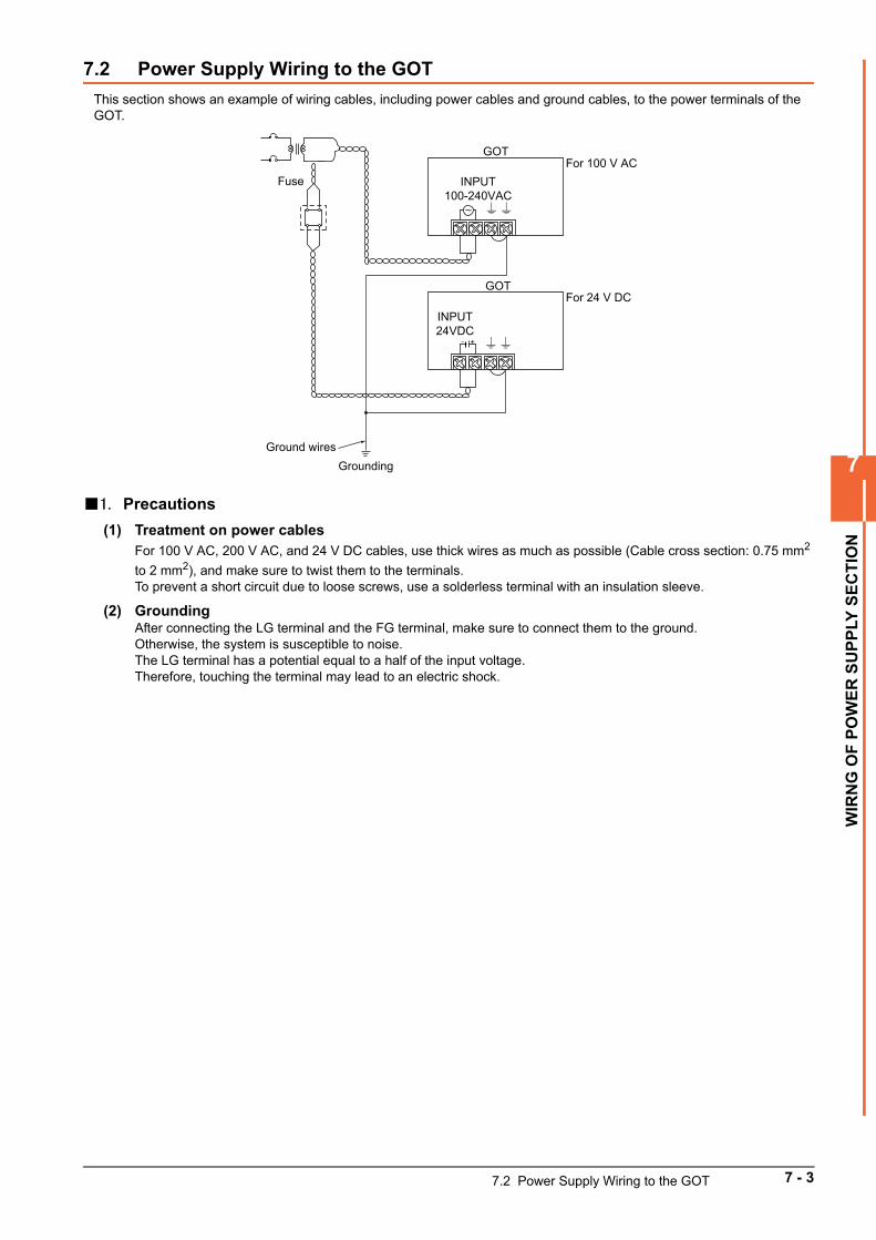
7
WIR
NG
OF
PO
WE
R S
UP
PLY
SE
CT
ION
7.2 Power Supply Wiring to the GOT
This section shows an example of wiring cables, including power cables and ground cables, to the power terminals of the GOT.
1. Precautions
(1) Treatment on power cablesFor 100 V AC, 200 V AC, and 24 V DC cables, use thick wires as much as possible (Cable cross section: 0.75 mm2
to 2 mm2), and make sure to twist them to the terminals.To prevent a short circuit due to loose screws, use a solderless terminal with an insulation sleeve.
(2) GroundingAfter connecting the LG terminal and the FG terminal, make sure to connect them to the ground.Otherwise, the system is susceptible to noise.The LG terminal has a potential equal to a half of the input voltage.Therefore, touching the terminal may lead to an electric shock.
INPUT100-240VAC
GOT
INPUT24VDC
FuseFor 100 V AC
+-
Ground wiresGrounding
For 24 V DCGOT
7.2 Power Supply Wiring to the GOT 7 - 3
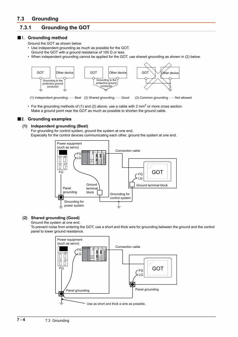
7.3 Grounding
7.3.1 Grounding the GOT
1. Grounding methodGround the GOT as shown below.• Use independent grounding as much as possible for the GOT.
Ground the GOT with a ground resistance of 100 Ω or less. • When independent grounding cannot be applied for the GOT, use shared grounding as shown in (2) below.
• For the grounding methods of (1) and (2) above, use a cable with 2 mm2 or more cross section.Make a ground point near the GOT as much as possible to shorten the ground cable.
2. Grounding examples
(1) Independent grounding (Best)For grounding for control system, ground the system at one end.Especially for the control devices communicating each other, ground the system at one end.
(2) Shared grounding (Good)Ground the system at one end.To prevent noise from entering the GOT, use a short and thick wire for grounding between the ground and the control panel to lower ground resistance.
GOT GOT GOT Other device Other device Other device
Grounding to the protective ground
conductor
Grounding to the protective ground
conductor
(1) Independent grounding Best (2) Shared grounding Good (3) Common grounding Not allowed …… …… ……
GOT
CN1A CN1B
CN2 CN3
FGLG
Grounding for control system
Ground terminal block
Connection cable
Panel grounding
Grounding for power system
FG
FG
LG
Power equipment (such as servo)
Ground terminal block
GOT
CN1A CN1B
CN2 CN3
FGLG
Connection cable
Panel grounding Panel grounding
Use as short and thick a wire as possible.
FG
FG
LG
Power equipment (such as servo)
7 - 4 7.3 Grounding
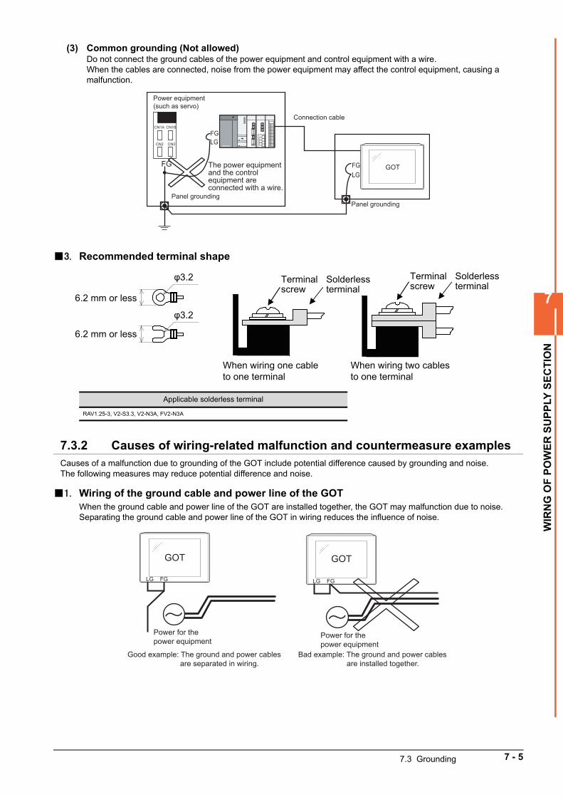
7
WIR
NG
OF
PO
WE
R S
UP
PLY
SE
CT
ION
(3) Common grounding (Not allowed)Do not connect the ground cables of the power equipment and control equipment with a wire.When the cables are connected, noise from the power equipment may affect the control equipment, causing a malfunction.
3. Recommended terminal shape
7.3.2 Causes of wiring-related malfunction and countermeasure examplesCauses of a malfunction due to grounding of the GOT include potential difference caused by grounding and noise.The following measures may reduce potential difference and noise.
1. Wiring of the ground cable and power line of the GOTWhen the ground cable and power line of the GOT are installed together, the GOT may malfunction due to noise.Separating the ground cable and power line of the GOT in wiring reduces the influence of noise.
Applicable solderless terminal
RAV1.25-3, V2-S3.3, V2-N3A, FV2-N3A
GOTFGLG
Connection cable
Panel groundingPanel grounding
FG
FG
CN1BCN1A
CN3CN2 LG
Power equipment (such as servo)
The power equipment and the control equipment are connected with a wire.
Terminal screw
Solderless terminal
Terminal screw
6.2 mm or less
φ3.2
φ3.2
6.2 mm or less
When wiring one cable to one terminal
When wiring two cables to one terminal
Solderless terminal
GOT
FGLG
Power for the power equipment
Good example: The ground and power cables are separated in wiring.
Power for the power equipment
Bad example: The ground and power cables are installed together.
GOT
FGLG
7.3 Grounding 7 - 5
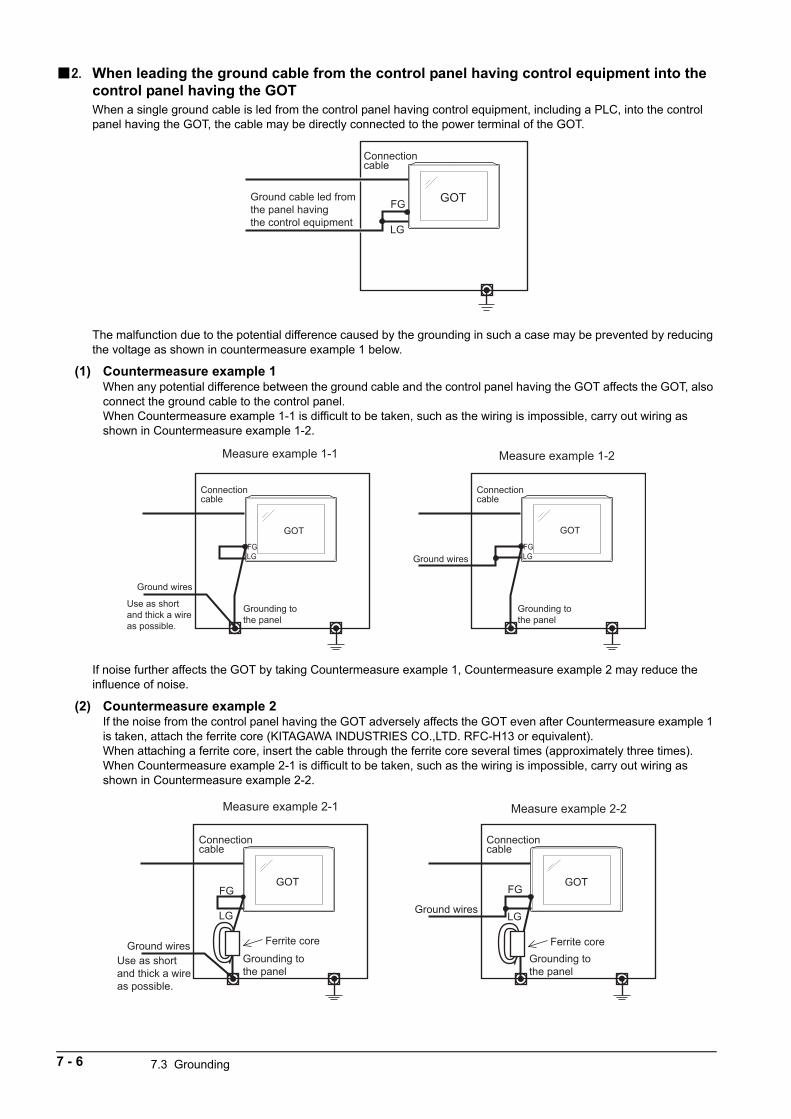
2. When leading the ground cable from the control panel having control equipment into the control panel having the GOTWhen a single ground cable is led from the control panel having control equipment, including a PLC, into the control panel having the GOT, the cable may be directly connected to the power terminal of the GOT.
The malfunction due to the potential difference caused by the grounding in such a case may be prevented by reducing the voltage as shown in countermeasure example 1 below.
(1) Countermeasure example 1When any potential difference between the ground cable and the control panel having the GOT affects the GOT, also connect the ground cable to the control panel.When Countermeasure example 1-1 is difficult to be taken, such as the wiring is impossible, carry out wiring as shown in Countermeasure example 1-2.
If noise further affects the GOT by taking Countermeasure example 1, Countermeasure example 2 may reduce the influence of noise.
(2) Countermeasure example 2If the noise from the control panel having the GOT adversely affects the GOT even after Countermeasure example 1 is taken, attach the ferrite core (KITAGAWA INDUSTRIES CO.,LTD. RFC-H13 or equivalent).When attaching a ferrite core, insert the cable through the ferrite core several times (approximately three times).When Countermeasure example 2-1 is difficult to be taken, such as the wiring is impossible, carry out wiring as shown in Countermeasure example 2-2.
Connection cable
Ground cable led from the panel having the control equipment
GOTFG
LG
GOT
Grounding to the panel
Ground wires
Use as short and thick a wire as possible.
FGLG
Connection cable
Measure example 1-1 Measure example 1-2
GOT
Grounding to the panel
Ground wiresFGLG
Connection cable
GOT
Grounding to the panel
Ferrite coreGround wiresUse as short and thick a wire as possible.
FG
LG
Connection cable
GOT
Grounding to the panel
Ground wires
FG
LG
Connection cable
Ferrite core
Measure example 2-1 Measure example 2-2
7 - 6 7.3 Grounding
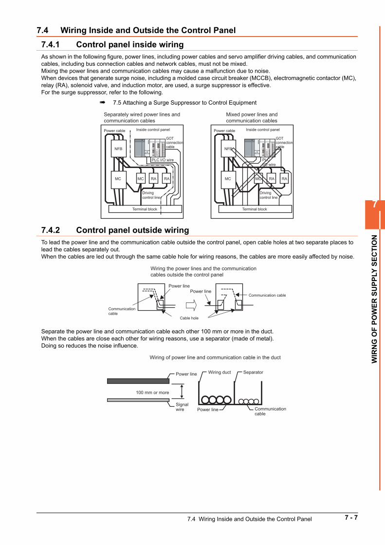
7
WIR
NG
OF
PO
WE
R S
UP
PLY
SE
CT
ION
7.4 Wiring Inside and Outside the Control Panel
7.4.1 Control panel inside wiringAs shown in the following figure, power lines, including power cables and servo amplifier driving cables, and communication cables, including bus connection cables and network cables, must not be mixed.Mixing the power lines and communication cables may cause a malfunction due to noise.When devices that generate surge noise, including a molded case circuit breaker (MCCB), electromagnetic contactor (MC), relay (RA), solenoid valve, and induction motor, are used, a surge suppressor is effective.For the surge suppressor, refer to the following.
7.5 Attaching a Surge Suppressor to Control Equipment
7.4.2 Control panel outside wiringTo lead the power line and the communication cable outside the control panel, open cable holes at two separate places to lead the cables separately out.When the cables are led out through the same cable hole for wiring reasons, the cables are more easily affected by noise.
Separate the power line and communication cable each other 100 mm or more in the duct.When the cables are close each other for wiring reasons, use a separator (made of metal).Doing so reduces the noise influence.
Terminal block
Inside control panel
Separately wired power lines and communication cables
Power cable
GOT connection cable
PLC I/O wire
Driving control line
NFB
MC MC RA RA
Terminal block
Inside control panel
Mixed power lines and communication cables
Power cable
NFB
MC MC RA RA
GOT connection cable
PLC I/O wire
Driving control line
Power line
Communication cable
Cable hole
Power lineCommunication cable
Wiring the power lines and the communication cables outside the control panel
Power line Wiring duct Separator
Power lineSignal wire Communication
cable
100 mm or more
Wiring of power line and communication cable in the duct
7.4 Wiring Inside and Outside the Control Panel 7 - 7
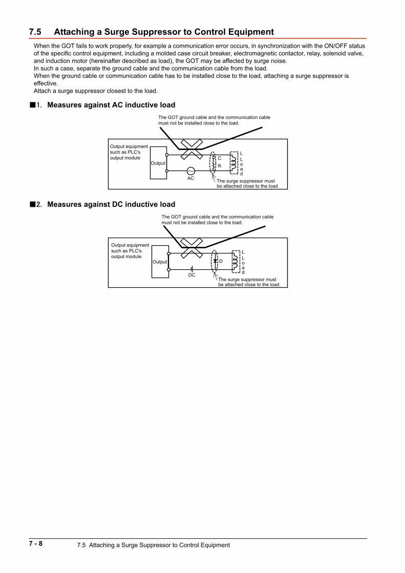
7.5 Attaching a Surge Suppressor to Control Equipment
When the GOT fails to work properly, for example a communication error occurs, in synchronization with the ON/OFF status of the specific control equipment, including a molded case circuit breaker, electromagnetic contactor, relay, solenoid valve, and induction motor (hereinafter described as load), the GOT may be affected by surge noise.In such a case, separate the ground cable and the communication cable from the load.When the ground cable or communication cable has to be installed close to the load, attaching a surge suppressor is effective.Attach a surge suppressor closest to the load.
1. Measures against AC inductive load
2. Measures against DC inductive load
AC
CR
Output equipment such as PLC's output module
The surge suppressor must be attached close to the load.
The GOT ground cable and the communication cable must not be installed close to the load.
Output
L Load
DC
D
Output equipment such as PLC's output module
The surge suppressor must be attached close to the load.
The GOT ground cable and the communication cable must not be installed close to the load.
Output
L
Load
7 - 8 7.5 Attaching a Surge Suppressor to Control Equipment
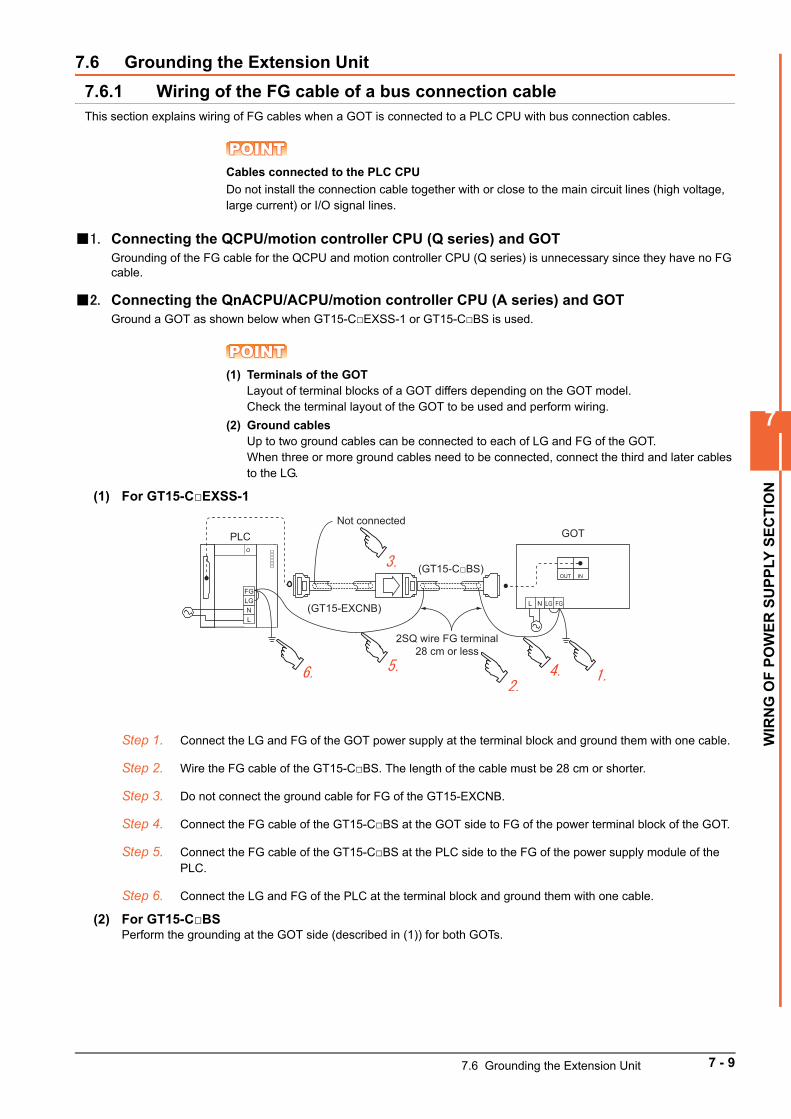
7
WIR
NG
OF
PO
WE
R S
UP
PLY
SE
CT
ION
7.6 Grounding the Extension Unit
7.6.1 Wiring of the FG cable of a bus connection cableThis section explains wiring of FG cables when a GOT is connected to a PLC CPU with bus connection cables.
POINTPOINTPOINTCables connected to the PLC CPU
Do not install the connection cable together with or close to the main circuit lines (high voltage, large current) or I/O signal lines.
1. Connecting the QCPU/motion controller CPU (Q series) and GOTGrounding of the FG cable for the QCPU and motion controller CPU (Q series) is unnecessary since they have no FG cable.
2. Connecting the QnACPU/ACPU/motion controller CPU (A series) and GOTGround a GOT as shown below when GT15-CEXSS-1 or GT15-CBS is used.
POINTPOINTPOINT(1) Terminals of the GOT
Layout of terminal blocks of a GOT differs depending on the GOT model.Check the terminal layout of the GOT to be used and perform wiring.
(2) Ground cablesUp to two ground cables can be connected to each of LG and FG of the GOT.When three or more ground cables need to be connected, connect the third and later cables to the LG.
(1) For GT15-CEXSS-1
Step 1. Connect the LG and FG of the GOT power supply at the terminal block and ground them with one cable.
Step 2. Wire the FG cable of the GT15-CBS. The length of the cable must be 28 cm or shorter.
Step 3. Do not connect the ground cable for FG of the GT15-EXCNB.
Step 4. Connect the FG cable of the GT15-CBS at the GOT side to FG of the power terminal block of the GOT.
Step 5. Connect the FG cable of the GT15-CBS at the PLC side to the FG of the power supply module of the PLC.
Step 6. Connect the LG and FG of the PLC at the terminal block and ground them with one cable.
(2) For GT15-CBSPerform the grounding at the GOT side (described in (1)) for both GOTs.
FGLGNL
PLCNot connected
(GT15-EXCNB)
GOT
OUT IN
FGLGNL
2SQ wire FG terminal28 cm or less
(GT15-CBS)
7.6 Grounding the Extension Unit 7 - 9

7 - 10 7.6 Grounding the Extension Unit
8
OP
ER
AT
ING
TH
E G
OT
8. OPERATING THE GOT
8.1 Outline Procedure to Start the GOT . . . . . . . . . . . . . . . . . . . . . . 8 - 2
8.2 Creating Project Data . . . . . . . . . . . . . . . . . . . . . . . . . . . . . . . . . . 8 - 5
8 - 1
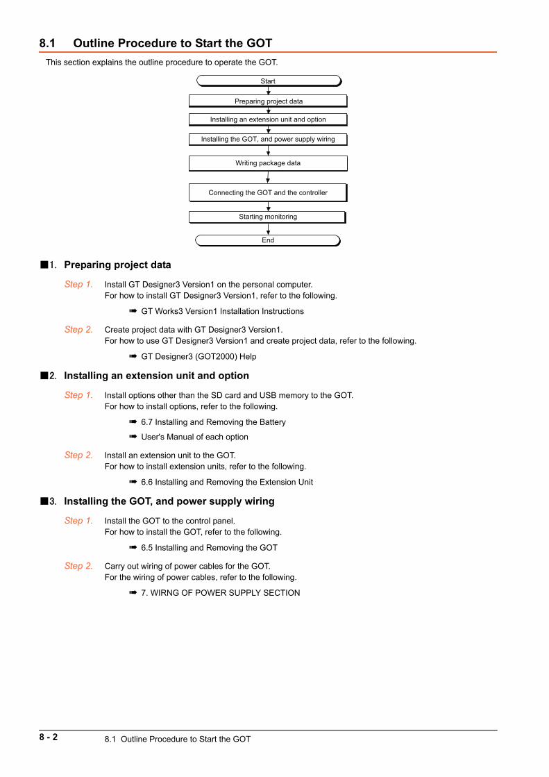
8.1 Outline Procedure to Start the GOT
This section explains the outline procedure to operate the GOT.
1. Preparing project data
Step 1. Install GT Designer3 Version1 on the personal computer.For how to install GT Designer3 Version1, refer to the following.
GT Works3 Version1 Installation Instructions
Step 2. Create project data with GT Designer3 Version1.For how to use GT Designer3 Version1 and create project data, refer to the following.
GT Designer3 (GOT2000) Help
2. Installing an extension unit and option
Step 1. Install options other than the SD card and USB memory to the GOT.For how to install options, refer to the following.
6.7 Installing and Removing the Battery
User's Manual of each option
Step 2. Install an extension unit to the GOT.For how to install extension units, refer to the following.
6.6 Installing and Removing the Extension Unit
3. Installing the GOT, and power supply wiring
Step 1. Install the GOT to the control panel.For how to install the GOT, refer to the following.
6.5 Installing and Removing the GOT
Step 2. Carry out wiring of power cables for the GOT.For the wiring of power cables, refer to the following.
7. WIRNG OF POWER SUPPLY SECTION
Start
Preparing project data
Installing an extension unit and option
Connecting the GOT and the controller
Starting monitoring
End
Writing package data
Installing the GOT, and power supply wiring
8 - 2 8.1 Outline Procedure to Start the GOT
8
OP
ER
AT
ING
TH
E G
OT
4. Writing package dataWrite package data with GT Designer3 Version1.The writing procedure differs depending on the data writing method.
POINTPOINTPOINTTerms
(1) Basic softwareThe basic software is equivalent to an operating system of the GOT.A GOT in which no basic software is written cannot be started.
(2) Package dataThe package data contains project data and applications necessary to execute the project data.Writing the package data into the GOT enables you to use the user-created project data on the GOT.
(1) Writing package data directly from a personal computer to the GOTConnect the GOT and a personal computer, and write the package data to the GOT.
Step 1. Connect the personal computer and GOT.• USB:
Connect the USB interface (Device) and the USB port of the personal computer with a USB cable.• Ethernet:
Connect the Ethernet interface and the Ethernet port of the personal computer with an Ethernet cable.To write the package data to the GOT by Ethernet, install the basic software to the GOT and configure the communication settings to enable the communication between the GOT and the personal computer by Ethernet in advance.
• Modem:Connect the RS-232 interface and the personal computer via a modem.
• Via PLC:Connect the GOT and the personal computer via the PLC connected to the GOT.
For each connection setting, refer to the following.
GT Designer3 (GOT2000) Help
Step 2. Turn on the GOT.
Step 3. Write the package data with GT Designer3 Version1.For how to write the package data, refer to the following.
GT Designer3 (GOT2000) Help
(2) Writing package data from the data storage to the GOTWrite the package data to the GOT using the data storage such as an SD card.
Step 1. Install a data storage such as an SD card to the personal computer.
Step 2. Write the package data to the data storage with GT Designer3 Version1.For how to write the package data, refer to the following.
GT Designer3 (GOT2000) Help
Step 3. Install the data storage to the GOT.• SD card (A drive): Insert the card to the SD card interface.• USB memory (Drive B): Insert the memory to the USB interface (Host).• Other data storage (Drive B to drive G): Connect the storage to the USB interface (Host).
8.1 Outline Procedure to Start the GOT 8 - 3
Step 4. Turn on the GOT.To start the GOT with the built-in flash memory (Drive C), write the package data to the built-in flash memory (Drive C) of the GOT.For how to write the package data, refer to the following.
GOT2000 Series User's Manual (Utility)
To start the GOT with the data storage (Drive A, B, D to G), writing the package data to the built-in flash memory (Drive C) of the GOT is not required.
5. Connecting the GOT and the controller
Step 1. Check the communication settings in the utility screen of the GOT.
GOT2000 Series User's Manual (Utility)
Step 2. Turn off the power of the GOT.
Step 3. Connect the GOT and controller with a cable.
GOT2000 Series Connection Manual
6. Starting monitoring
Step 1. Turn on the GOT and the connected system.
Step 2. The GOT starts monitoring.
POINTPOINTPOINTPrecautions when the startup source of the GOT is any other than the built-in flash memory (Drive C)
(1) GOT startup timeThe GOT startup time is longer than the normal startup time.The GOT startup time differs depending on the data storage type, number of written applications, and package data size.
(2) Handling the SD card during the GOT startupWhen the startup source is the SD card (Drive A), do not open the cover of the SD card interface during the GOT startup.Doing so causes the GOT to fail to start normally.
(3) Corrective actions when the GOT cannot be startedThe GOT cannot be started in any of the following conditions.Take the following corrective actions, and turn on the GOT again.
Condition Corrective action
The type of the physical GOT differs from the
GOT type of the package data stored in the SD
card.
Prepare the SD card that stores the package
data containing the GOT type same as the GOT
to be used.
The GOT has insufficient memory.
Delete unnecessary data in the memory of the
GOT.
GT Designer3 (GOT2000) Help
8 - 4 8.1 Outline Procedure to Start the GOT
8
OP
ER
AT
ING
TH
E G
OT
8.2 Creating Project Data
Create project data with GT Designer3 Version1.For how to operate GT Designer3 Version1, refer to the following.
GT Designer3 (GOT2000) Help
1. Precautions for drawing
(1) Starting GT Designer3 Version1When starting GT Designer3 Version1, make sure to start the GOT2000 application.You cannot create the GOT2000 screens with the GOT1000 application.
8.2 Creating Project Data 8 - 5

8 - 6 8.2 Creating Project Data
MA
INT
EN
AN
CE
AN
D IN
SP
EC
TIO
N
9
9. MAINTENANCE AND INSPECTION
9.1 Daily Inspection . . . . . . . . . . . . . . . . . . . . . . . . . . . . . . . . . . . . . . 9 - 2
9.2 Periodic Inspection. . . . . . . . . . . . . . . . . . . . . . . . . . . . . . . . . . . . 9 - 2
9.3 Screen Cleaning Method . . . . . . . . . . . . . . . . . . . . . . . . . . . . . . . 9 - 4
9.4 Low-Voltage Battery Detection and Battery Replacement . . . . 9 - 5
9 - 1
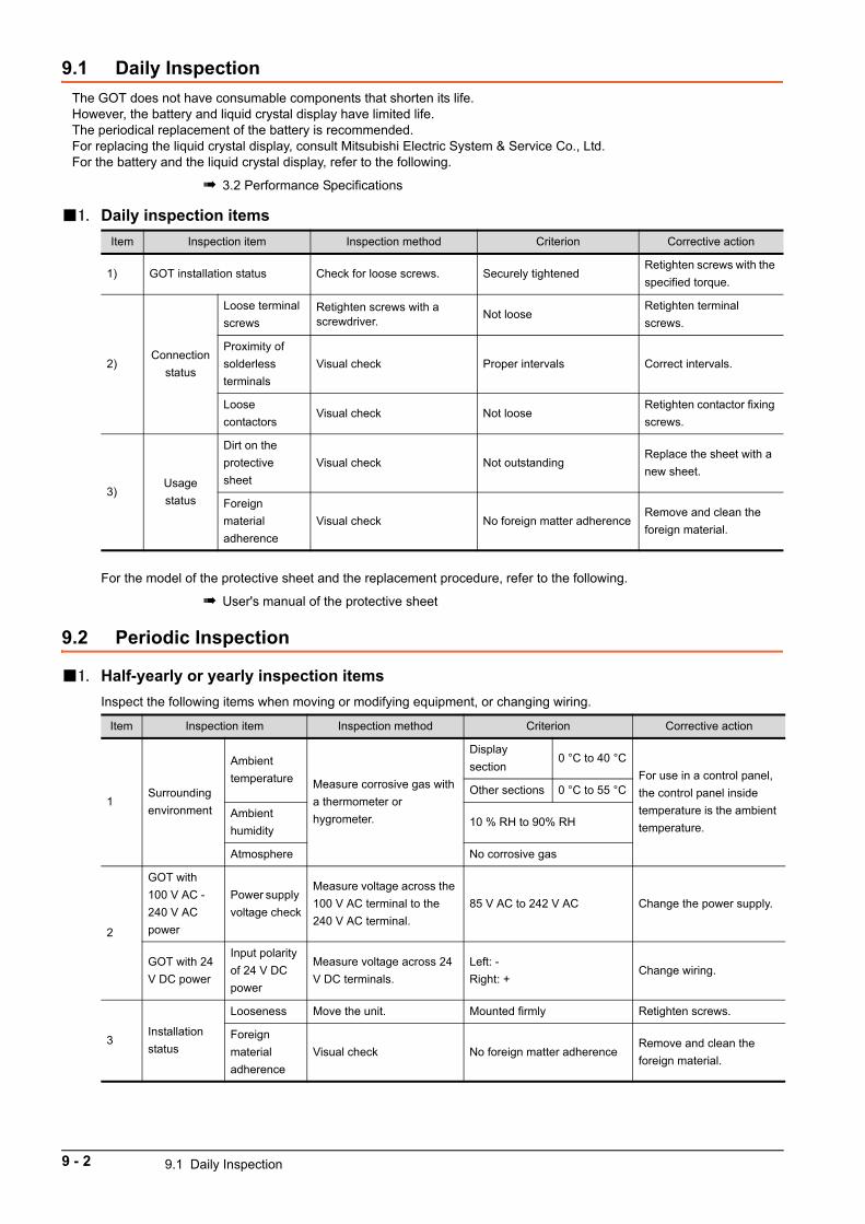
9.1 Daily Inspection
The GOT does not have consumable components that shorten its life.However, the battery and liquid crystal display have limited life.The periodical replacement of the battery is recommended.For replacing the liquid crystal display, consult Mitsubishi Electric System & Service Co., Ltd.For the battery and the liquid crystal display, refer to the following.
3.2 Performance Specifications
1. Daily inspection items
For the model of the protective sheet and the replacement procedure, refer to the following.
User's manual of the protective sheet
9.2 Periodic Inspection
1. Half-yearly or yearly inspection items
Inspect the following items when moving or modifying equipment, or changing wiring.
Item Inspection item Inspection method Criterion Corrective action
1) GOT installation status Check for loose screws. Securely tightenedRetighten screws with the
specified torque.
2)Connection
status
Loose terminal
screwsRetighten screws with a screwdriver.
Not looseRetighten terminal
screws.
Proximity of
solderless
terminals
Visual check Proper intervals Correct intervals.
Loose
contactorsVisual check Not loose
Retighten contactor fixing
screws.
3)Usage
status
Dirt on the
protective
sheet
Visual check Not outstandingReplace the sheet with a
new sheet.
Foreign
material
adherence
Visual check No foreign matter adherenceRemove and clean the
foreign material.
Item Inspection item Inspection method Criterion Corrective action
1Surrounding
environment
Ambient
temperature Measure corrosive gas with
a thermometer or
hygrometer.
Display
section0 °C to 40 °C
For use in a control panel,
the control panel inside
temperature is the ambient
temperature.
Other sections 0 °C to 55 °C
Ambient
humidity10 % RH to 90% RH
Atmosphere No corrosive gas
2
GOT with
100 V AC -
240 V AC
power
Power supply
voltage check
Measure voltage across the
100 V AC terminal to the
240 V AC terminal.
85 V AC to 242 V AC Change the power supply.
GOT with 24
V DC power
Input polarity
of 24 V DC
power
Measure voltage across 24
V DC terminals.
Left: -
Right: +Change wiring.
3Installation
status
Looseness Move the unit. Mounted firmly Retighten screws.
Foreign
material
adherence
Visual check No foreign matter adherenceRemove and clean the
foreign material.
9 - 2 9.1 Daily Inspection
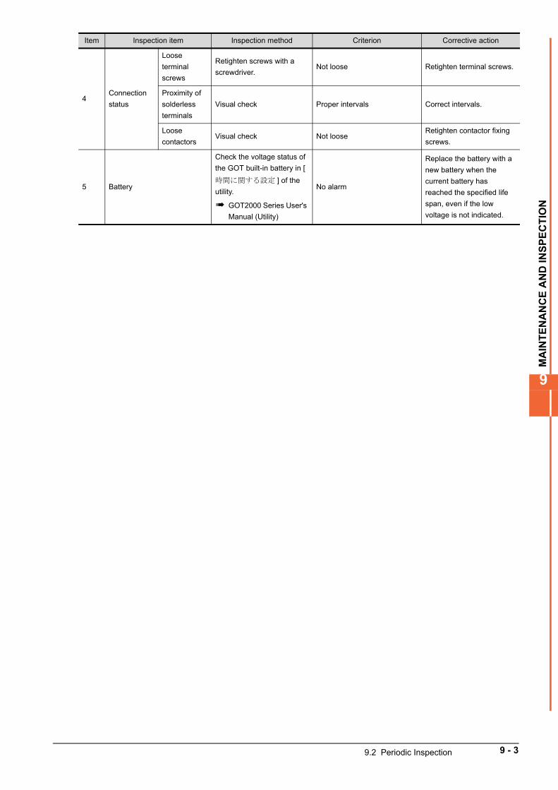
MA
INT
EN
AN
CE
AN
D IN
SP
EC
TIO
N
9
4Connection
status
Loose
terminal
screws
Retighten screws with a
screwdriver.Not loose Retighten terminal screws.
Proximity of
solderless
terminals
Visual check Proper intervals Correct intervals.
Loose
contactorsVisual check Not loose
Retighten contactor fixing
screws.
5 Battery
Check the voltage status of
the GOT built-in battery in [
時間に関する設定 ] of the
utility.
GOT2000 Series User's
Manual (Utility)
No alarm
Replace the battery with a
new battery when the
current battery has
reached the specified life
span, even if the low
voltage is not indicated.
Item Inspection item Inspection method Criterion Corrective action
9.2 Periodic Inspection 9 - 3
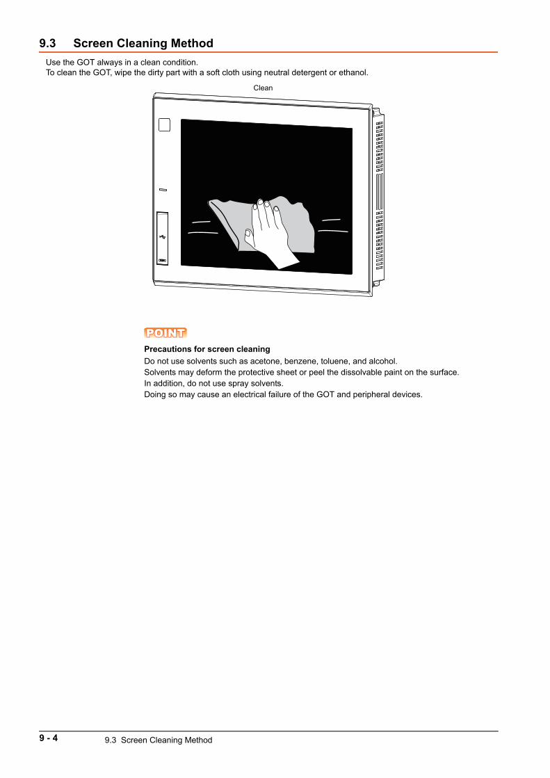
9.3 Screen Cleaning Method
Use the GOT always in a clean condition.To clean the GOT, wipe the dirty part with a soft cloth using neutral detergent or ethanol.
POINTPOINTPOINTPrecautions for screen cleaning
Do not use solvents such as acetone, benzene, toluene, and alcohol.Solvents may deform the protective sheet or peel the dissolvable paint on the surface.In addition, do not use spray solvents.Doing so may cause an electrical failure of the GOT and peripheral devices.
Clean
9 - 4 9.3 Screen Cleaning Method
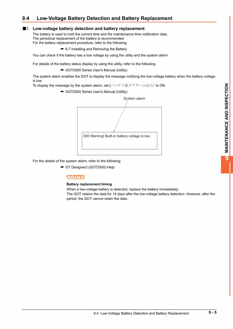
MA
INT
EN
AN
CE
AN
D IN
SP
EC
TIO
N
9
9.4 Low-Voltage Battery Detection and Battery Replacement
1. Low-voltage battery detection and battery replacementThe battery is used to hold the current time and the maintenance time notification data.The periodical replacement of the battery is recommended.For the battery replacement procedure, refer to the following.
6.7 Installing and Removing the Battery
You can check if the battery has a low voltage by using the utility and the system alarm.
For details of the battery status display by using the utility, refer to the following.
GOT2000 Series User's Manual (Utility)
The system alarm enables the GOT to display the message notifying the low-voltage battery when the battery voltage is low.To display the message by the system alarm, set [バッテリ低下アラーム出力] to ON.
GOT2000 Series User's Manual (Utility)
For the details of the system alarm, refer to the following.
GT Designer3 (GOT2000) Help
POINTPOINTPOINTBattery replacement timing
When a low-voltage battery is detected, replace the battery immediately.The GOT retains the data for 14 days after the low-voltage battery detection. However, after the period, the GOT cannot retain the data.
System alarm
500 Warning! Built-in battery voltage is low.
9.4 Low-Voltage Battery Detection and Battery Replacement 9 - 5
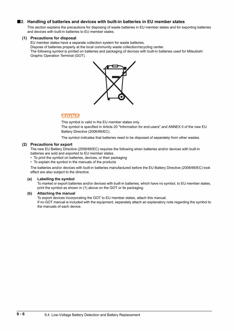
2. Handling of batteries and devices with built-in batteries in EU member statesThis section explains the precautions for disposing of waste batteries in EU member states and for exporting batteries and devices with built-in batteries to EU member states.
(1) Precautions for disposalEU member states have a separate collection system for waste batteries.Dispose of batteries properly at the local community waste collection/recycling center.The following symbol is printed on batteries and packaging of devices with built-in batteries used for Mitsubishi Graphic Operation Terminal (GOT).
POINTPOINTPOINTThis symbol is valid in the EU member states only.The symbol is specified in Article 20 "Information for end-users" and ANNEX II of the new EU Battery Directive (2006/66/EC).
The symbol indicates that batteries need to be disposed of separately from other wastes.
(2) Precautions for exportThe new EU Battery Directive (2006/66/EC) requires the following when batteries and/or devices with built-in batteries are sold and exported to EU member states.• To print the symbol on batteries, devices, or their packaging• To explain the symbol in the manuals of the products
The batteries and/or devices with built-in batteries manufactured before the EU Battery Directive (2006/66/EC) took effect are also subject to the directive.
(a) Labelling the symbolTo market or export batteries and/or devices with built-in batteries, which have no symbol, to EU member states, print the symbol as shown in (1) above on the GOT or its packaging.
(b) Attaching the manualTo export devices incorporating the GOT to EU member states, attach this manual.If no GOT manual is included with the equipment, separately attach an explanatory note regarding the symbol to the manuals of each device.
9 - 6 9.4 Low-Voltage Battery Detection and Battery Replacement
TR
OU
BL
ES
HO
OT
ING
10
10. TROUBLESHOOTING
10.1 GOT Restoration Sheets . . . . . . . . . . . . . . . . . . . . . . . . . . . . . . 10 - 2
10.2 Troubleshooting for the Bus Connection. . . . . . . . . . . . . . . . 10 - 14
10.3 Error Messages and System Alarms . . . . . . . . . . . . . . . . . . . 10 - 17
10 - 1
10.1 GOT Restoration Sheets
This section provides check sheets for restoration in cases where the GOT does not operate normally.The following explains how to use each sheet.
1. When the GOT does not operate or malfunctions (GOT status check sheet)When the GOT does not operate or malfunctions, identify the cause of the malfunction using the GOT status check sheet, and take a corrective action.When the GOT is restored, see the status for a while.
2. When the wiring needs to be improved (GOT installation status check sheet)As a result of the above check (1), the cause of the malfunction or others is thought to be due to the noise generated by the GOT wiring status, take a corrective action for wiring by using the GOT installation status check sheet.When the GOT is restored, see the status for a while.
3. When a corrective action other than the above is required (System configuration check sheet)If a malfunction or others still occurs even after the above checks, fill out the system configuration check sheet with details about your system, and consult your local Mitsubishi Electric System & Service Co., Ltd.When sending a faulty product, attach the GOT restoration sheets (GOT status check sheet, GOT installation status check sheet, and the system configuration check sheet) checked in this section.Keep copies of the restoration sheets.
10 - 2 10.1 GOT Restoration Sheets
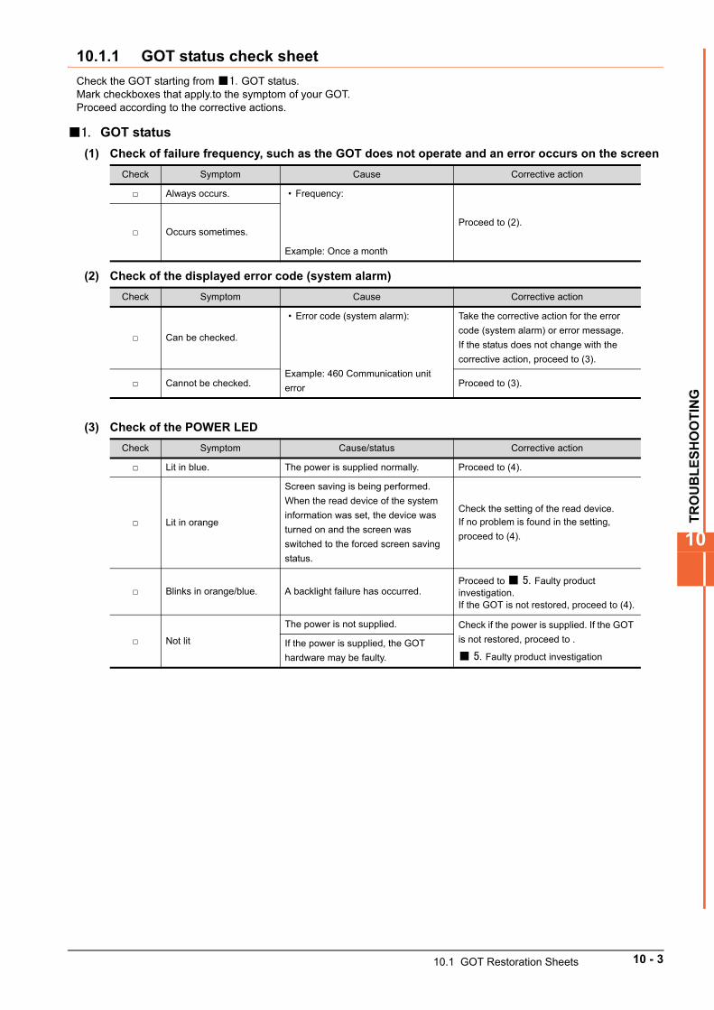
TR
OU
BL
ES
HO
OT
ING
10
10.1.1 GOT status check sheet
Check the GOT starting from 1. GOT status.Mark checkboxes that apply.to the symptom of your GOT.Proceed according to the corrective actions.
1. GOT status
(1) Check of failure frequency, such as the GOT does not operate and an error occurs on the screen
(2) Check of the displayed error code (system alarm)
(3) Check of the POWER LED
Check Symptom Cause Corrective action
Always occurs. • Frequency:
Example: Once a month
Proceed to (2). Occurs sometimes.
Check Symptom Cause Corrective action
Can be checked.
• Error code (system alarm):
Example: 460 Communication unit
error
Take the corrective action for the error
code (system alarm) or error message.
If the status does not change with the
corrective action, proceed to (3).
Cannot be checked. Proceed to (3).
Check Symptom Cause/status Corrective action
Lit in blue. The power is supplied normally. Proceed to (4).
Lit in orange
Screen saving is being performed.
When the read device of the system
information was set, the device was
turned on and the screen was
switched to the forced screen saving
status.
Check the setting of the read device.If no problem is found in the setting,
proceed to (4).
Blinks in orange/blue. A backlight failure has occurred.Proceed to 5. Faulty product investigation.If the GOT is not restored, proceed to (4).
Not lit
The power is not supplied. Check if the power is supplied. If the GOT
is not restored, proceed to .
5. Faulty product investigation
If the power is supplied, the GOT
hardware may be faulty.
10.1 GOT Restoration Sheets 10 - 3
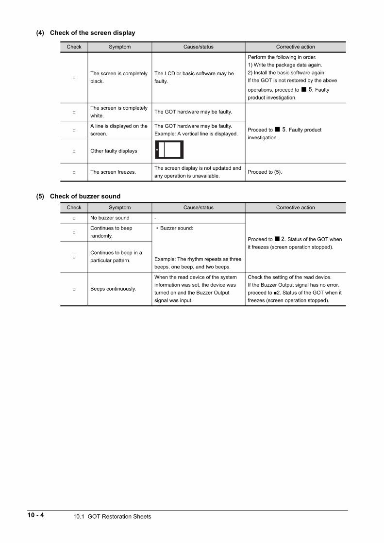
(4) Check of the screen display
(5) Check of buzzer sound
Check Symptom Cause/status Corrective action
The screen is completely
black.
The LCD or basic software may be
faulty.
Perform the following in order.
1) Write the package data again.
2) Install the basic software again.
If the GOT is not restored by the above
operations, proceed to 5. Faulty
product investigation.
The screen is completely
white.The GOT hardware may be faulty.
Proceed to 5. Faulty product
investigation.
A line is displayed on the
screen.
The GOT hardware may be faulty.
Example: A vertical line is displayed.
Other faulty displays
The screen freezes. The screen display is not updated and
any operation is unavailable.Proceed to (5).
Check Symptom Cause/status Corrective action
No buzzer sound -
Proceed to 2. Status of the GOT when
it freezes (screen operation stopped).
Continues to beep
randomly.
• Buzzer sound:
Example: The rhythm repeats as three
beeps, one beep, and two beeps.
Continues to beep in a
particular pattern.
Beeps continuously.
When the read device of the system
information was set, the device was
turned on and the Buzzer Output
signal was input.
Check the setting of the read device.
If the Buzzer Output signal has no error,
proceed to 2. Status of the GOT when it
freezes (screen operation stopped).
10 - 4 10.1 GOT Restoration Sheets
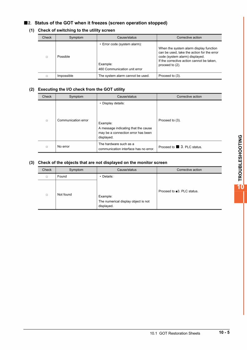
TR
OU
BL
ES
HO
OT
ING
10
2. Status of the GOT when it freezes (screen operation stopped)
(1) Check of switching to the utility screen
(2) Executing the I/O check from the GOT utility
(3) Check of the objects that are not displayed on the monitor screen
Check Symptom Cause/status Corrective action
Possible
• Error code (system alarm):
Example:
460 Communication unit error
When the system alarm display function can be used, take the action for the error code (system alarm) displayed.If the corrective action cannot be taken, proceed to (2).
Impossible The system alarm cannot be used. Proceed to (3).
Check Symptom Cause/status Corrective action
Communication error
• Display details:
Example:
A message indicating that the cause may be a connection error has been displayed.
Proceed to (3).
No errorThe hardware such as a
communication interface has no error.Proceed to 3. PLC status.
Check Symptom Cause/status Corrective action
Found • Details:
Example:
The numerical display object is not displayed.
Proceed to 3. PLC status. Not found
10.1 GOT Restoration Sheets 10 - 5
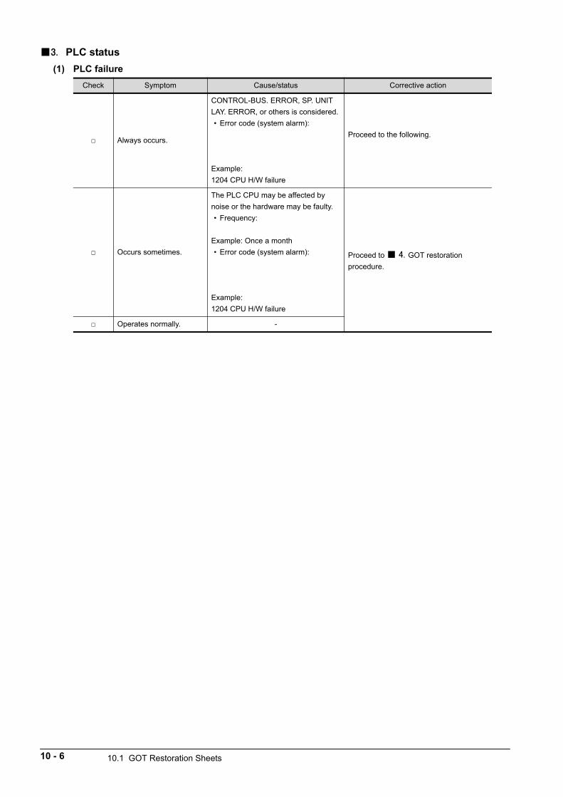
3. PLC status
(1) PLC failure
Check Symptom Cause/status Corrective action
Always occurs.
CONTROL-BUS. ERROR, SP. UNIT
LAY. ERROR, or others is considered.
• Error code (system alarm):
Example:
1204 CPU H/W failure
Proceed to the following.
Occurs sometimes.
The PLC CPU may be affected by
noise or the hardware may be faulty.
• Frequency:
Example: Once a month
• Error code (system alarm):
Example:
1204 CPU H/W failure
Proceed to 4. GOT restoration
procedure.
Operates normally. -
10 - 6 10.1 GOT Restoration Sheets
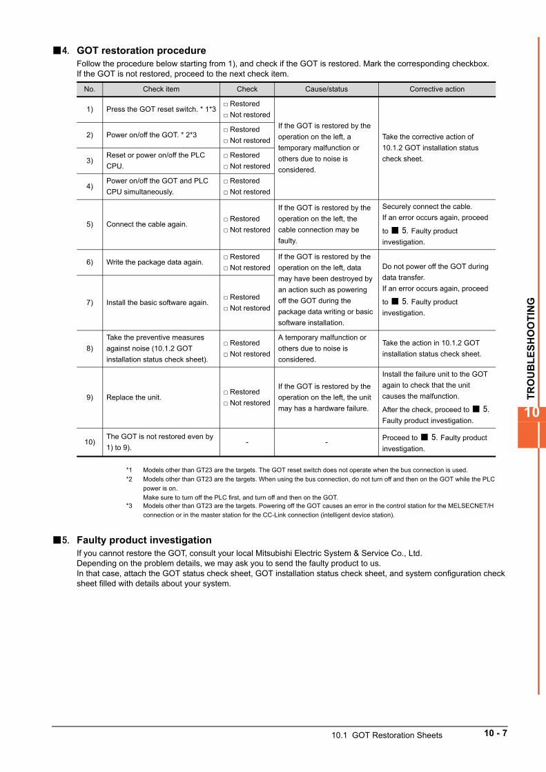
TR
OU
BL
ES
HO
OT
ING
10
4. GOT restoration procedureFollow the procedure below starting from 1), and check if the GOT is restored. Mark the corresponding checkbox.If the GOT is not restored, proceed to the next check item.
*1 Models other than GT23 are the targets. The GOT reset switch does not operate when the bus connection is used.
*2 Models other than GT23 are the targets. When using the bus connection, do not turn off and then on the GOT while the PLC
power is on.
Make sure to turn off the PLC first, and turn off and then on the GOT.*3 Models other than GT23 are the targets. Powering off the GOT causes an error in the control station for the MELSECNET/H
connection or in the master station for the CC-Link connection (intelligent device station).
5. Faulty product investigationIf you cannot restore the GOT, consult your local Mitsubishi Electric System & Service Co., Ltd.Depending on the problem details, we may ask you to send the faulty product to us.In that case, attach the GOT status check sheet, GOT installation status check sheet, and system configuration check sheet filled with details about your system.
No. Check item Check Cause/status Corrective action
1) Press the GOT reset switch. * 1*3 Restored
Not restored
If the GOT is restored by the
operation on the left, a
temporary malfunction or
others due to noise is
considered.
Take the corrective action of
10.1.2 GOT installation status
check sheet.
2) Power on/off the GOT. * 2*3 Restored
Not restored
3)Reset or power on/off the PLC
CPU.
Restored
Not restored
4)Power on/off the GOT and PLC
CPU simultaneously.
Restored
Not restored
5) Connect the cable again. Restored
Not restored
If the GOT is restored by the
operation on the left, the
cable connection may be
faulty.
Securely connect the cable.
If an error occurs again, proceed
to 5. Faulty product
investigation.
6) Write the package data again. Restored
Not restored
If the GOT is restored by the
operation on the left, data
may have been destroyed by
an action such as powering
off the GOT during the
package data writing or basic
software installation.
Do not power off the GOT during
data transfer.
If an error occurs again, proceed
to 5. Faulty product
investigation.
7) Install the basic software again. Restored
Not restored
8)
Take the preventive measures
against noise (10.1.2 GOT
installation status check sheet).
Restored
Not restored
A temporary malfunction or
others due to noise is
considered.
Take the action in 10.1.2 GOT
installation status check sheet.
9) Replace the unit. Restored
Not restored
If the GOT is restored by the
operation on the left, the unit
may has a hardware failure.
Install the failure unit to the GOT
again to check that the unit
causes the malfunction.
After the check, proceed to 5. Faulty product investigation.
10)The GOT is not restored even by
1) to 9).- -
Proceed to 5. Faulty product
investigation.
10.1 GOT Restoration Sheets 10 - 7
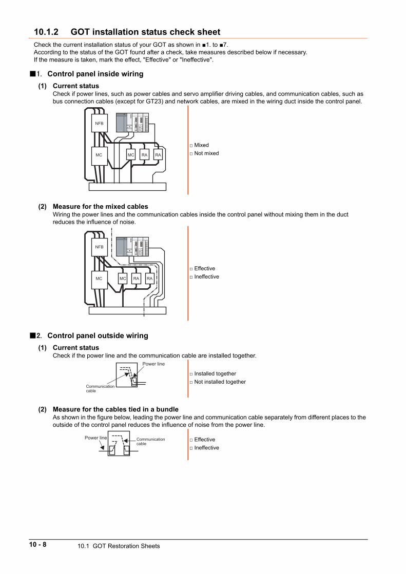
10.1.2 GOT installation status check sheetCheck the current installation status of your GOT as shown in 1. to 7.According to the status of the GOT found after a check, take measures described below if necessary.If the measure is taken, mark the effect, "Effective" or "Ineffective".
1. Control panel inside wiring
(1) Current statusCheck if power lines, such as power cables and servo amplifier driving cables, and communication cables, such as bus connection cables (except for GT23) and network cables, are mixed in the wiring duct inside the control panel.
(2) Measure for the mixed cablesWiring the power lines and the communication cables inside the control panel without mixing them in the duct reduces the influence of noise.
2. Control panel outside wiring
(1) Current statusCheck if the power line and the communication cable are installed together.
(2) Measure for the cables tied in a bundleAs shown in the figure below, leading the power line and communication cable separately from different places to the outside of the control panel reduces the influence of noise from the power line.
Mixed
Not mixed
Effective
Ineffective
Installed together
Not installed together
Effective
Ineffective
NFB
MC MC RA RA
NFB
MC MC RA RA
Power line
Communication cable
Communication cable
Power line
10 - 8 10.1 GOT Restoration Sheets
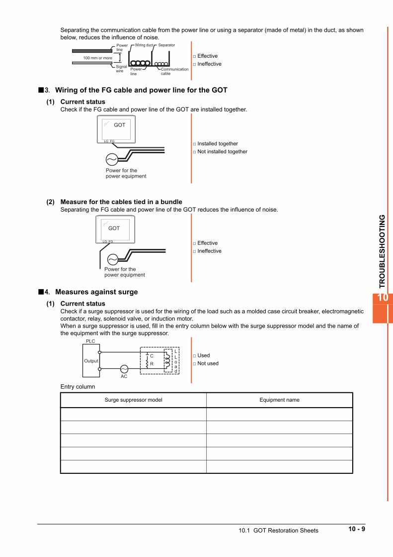
TR
OU
BL
ES
HO
OT
ING
10
Separating the communication cable from the power line or using a separator (made of metal) in the duct, as shown below, reduces the influence of noise.
3. Wiring of the FG cable and power line for the GOT
(1) Current statusCheck if the FG cable and power line of the GOT are installed together.
(2) Measure for the cables tied in a bundleSeparating the FG cable and power line of the GOT reduces the influence of noise.
4. Measures against surge
(1) Current statusCheck if a surge suppressor is used for the wiring of the load such as a molded case circuit breaker, electromagnetic contactor, relay, solenoid valve, or induction motor.When a surge suppressor is used, fill in the entry column below with the surge suppressor model and the name of the equipment with the surge suppressor.
Entry column
Effective
Ineffective
Installed together
Not installed together
Effective
Ineffective
Used
Not used
Surge suppressor model Equipment name
Power line
Wiring duct Separator
Power line
Signal wire Communication
cable
100 mm or more
GOT
LG FG
Power for the power equipment
GOT
Power for the power equipment
LG FG
AC
C
ROutput
L
Load
PLC
10.1 GOT Restoration Sheets 10 - 9
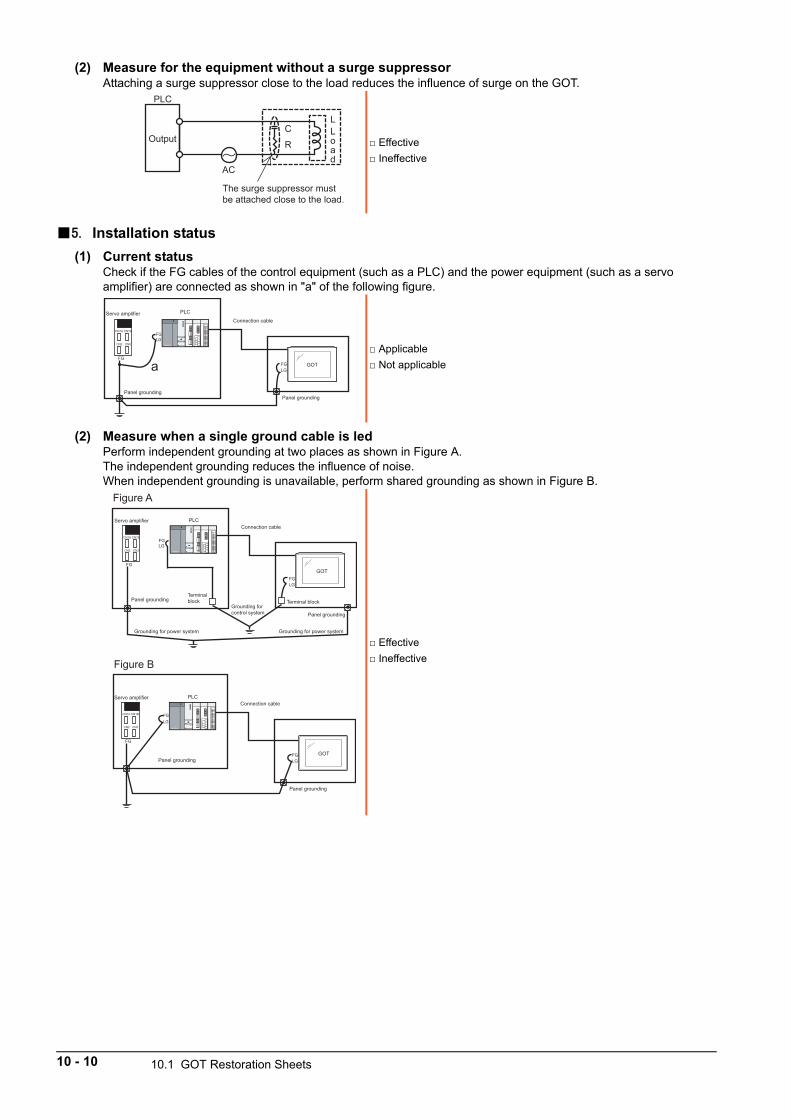
(2) Measure for the equipment without a surge suppressorAttaching a surge suppressor close to the load reduces the influence of surge on the GOT.
5. Installation status
(1) Current statusCheck if the FG cables of the control equipment (such as a PLC) and the power equipment (such as a servo amplifier) are connected as shown in "a" of the following figure.
(2) Measure when a single ground cable is ledPerform independent grounding at two places as shown in Figure A.The independent grounding reduces the influence of noise.When independent grounding is unavailable, perform shared grounding as shown in Figure B.
Effective
Ineffective
Applicable
Not applicable
Effective
Ineffective
AC
C
ROutput
L
Load
PLC
The surge suppressor must be attached close to the load.
GOTFGLG
Connection cable
Panel groundingPanel grounding
FG
FG
CN1BCN1A
CN3CN2LG
a
PLCServo amplifier
GOTFGLG
Connection cable
Panel grounding
Grounding for power system Grounding for power system
Grounding for control system
Terminal block Terminal block
Panel grounding
FG
FG
CN1BCN1A
CN3CN2LG
PLCServo amplifier
Figure A
GOTFGLG
Connection cable
Panel grounding
Panel grounding
FG
FG
CN1BCN1A
CN3CN2LG
PLCServo amplifier
Figure B
10 - 10 10.1 GOT Restoration Sheets
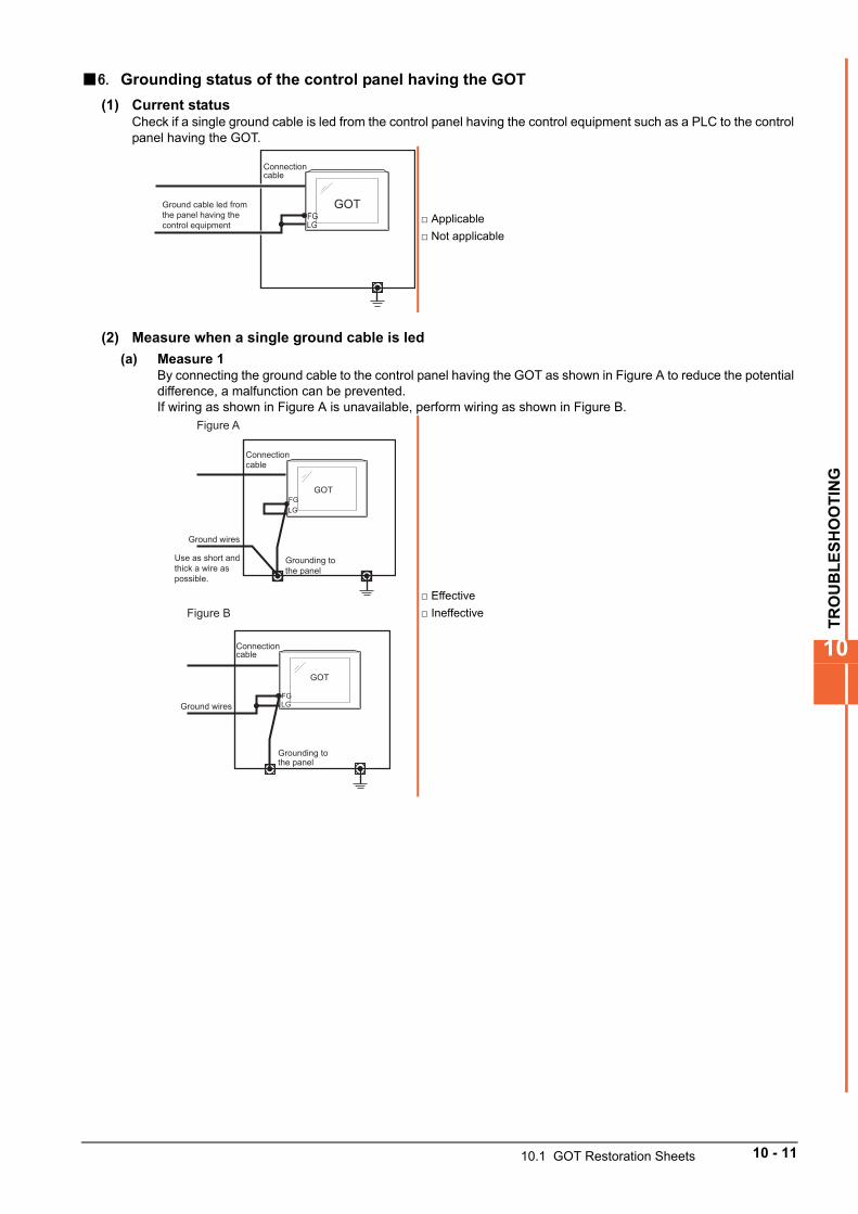
TR
OU
BL
ES
HO
OT
ING
10
6. Grounding status of the control panel having the GOT
(1) Current statusCheck if a single ground cable is led from the control panel having the control equipment such as a PLC to the control panel having the GOT.
(2) Measure when a single ground cable is led
(a) Measure 1By connecting the ground cable to the control panel having the GOT as shown in Figure A to reduce the potential difference, a malfunction can be prevented.If wiring as shown in Figure A is unavailable, perform wiring as shown in Figure B.
Applicable
Not applicable
Effective
Ineffective
Connection cable
Ground cable led from the panel having the control equipment
GOTFGLG
GOT
Grounding to the panel
Ground wires
Use as short and thick a wire as possible.
FGLG
Connection cable
Figure A
GOT
Grounding to the panel
Ground wiresFGLG
Connection cable
Figure B
10.1 GOT Restoration Sheets 10 - 11
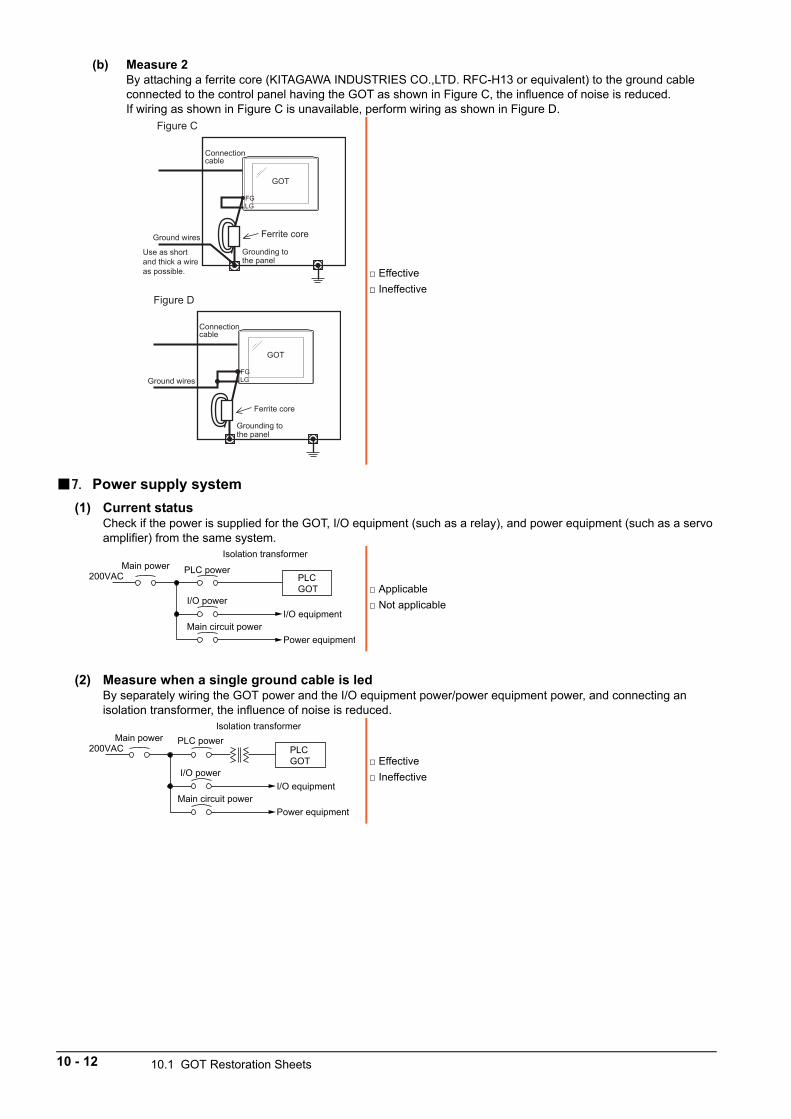
(b) Measure 2By attaching a ferrite core (KITAGAWA INDUSTRIES CO.,LTD. RFC-H13 or equivalent) to the ground cable connected to the control panel having the GOT as shown in Figure C, the influence of noise is reduced.If wiring as shown in Figure C is unavailable, perform wiring as shown in Figure D.
7. Power supply system
(1) Current statusCheck if the power is supplied for the GOT, I/O equipment (such as a relay), and power equipment (such as a servo amplifier) from the same system.
(2) Measure when a single ground cable is ledBy separately wiring the GOT power and the I/O equipment power/power equipment power, and connecting an isolation transformer, the influence of noise is reduced.
Effective
Ineffective
Applicable
Not applicable
Effective
Ineffective
GOT
Grounding to the panel
Ferrite coreGround wires
FGLG
Connection cable
Use as short and thick a wire as possible.
Figure C
GOT
Grounding to the panel
Ground wiresFGLG
Connection cable
Ferrite core
Figure D
Main power200VAC
I/O power
Main circuit power
Isolation transformer
PLCGOT
I/O equipment
Power equipment
PLC power
Main power200VAC
I/O power
Main circuit power
Isolation transformer
PLCGOT
I/O equipment
Power equipment
PLC power
10 - 12 10.1 GOT Restoration Sheets
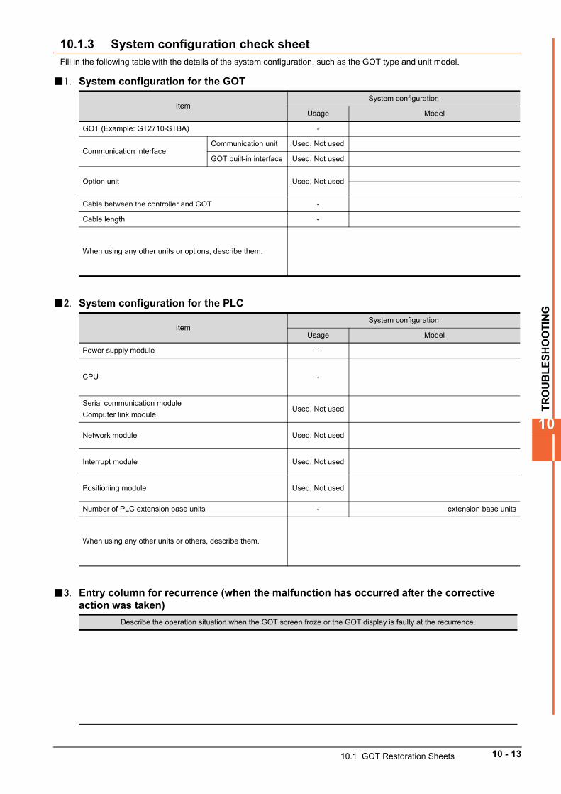
TR
OU
BL
ES
HO
OT
ING
10
10.1.3 System configuration check sheetFill in the following table with the details of the system configuration, such as the GOT type and unit model.
1. System configuration for the GOT
2. System configuration for the PLC
3. Entry column for recurrence (when the malfunction has occurred after the corrective action was taken)
ItemSystem configuration
Usage Model
GOT (Example: GT2710-STBA) -
Communication interfaceCommunication unit Used, Not used
GOT built-in interface Used, Not used
Option unit Used, Not used
Cable between the controller and GOT -
Cable length -
When using any other units or options, describe them.
ItemSystem configuration
Usage Model
Power supply module -
CPU -
Serial communication module
Computer link moduleUsed, Not used
Network module Used, Not used
Interrupt module Used, Not used
Positioning module Used, Not used
Number of PLC extension base units - extension base units
When using any other units or others, describe them.
Describe the operation situation when the GOT screen froze or the GOT display is faulty at the recurrence.
10.1 GOT Restoration Sheets 10 - 13
10.2 Troubleshooting for the Bus Connection
If an error occurs in the bus connection between the GOT and the PLC CPU and the cause is not clear with the system alarm, perform the troubleshooting described in this section.For the details of the system alarm, refer to the following.
GOT2000 Series User's Manual (Utility)For the details of the bus connection, refer to the following.
GOT2000 Series Connection Manual
10.2.1 Identifying the error positionThis section explains how to identify the error position.For the details of the PLC CPU error and special register, refer to the User's Manual of the PLC CPU used.
1. How to identify the error positionIdentify the error position, modify the sequence program or replace the module where the error occurs, and check whether the error occurs again.If the error occurs again, other causes are considered.Refer to the following to narrow possible error positions.
(1) Checking the error in the PLC
Step 1. Check the type of the error detected in the PLC using GX Works2 or others.
Step 2. Check each module and the installation and grounding status of the cables according to the error message on the PLC CPU.
(2) Checking the error occurrence timingCheck the timing of the error occurrence.
(a) An error occurs when the power is turned on or immediately after the PLC is reset.The error may be detected in the initial process of the PLC CPU.In this case, since the faulty module cannot be usually identified, set only the END instruction in the sequence program and remove the modules one by one.When the error is eliminated after a specific module has been removed, the module may have caused the error.
(b) An error occurs after or several seconds after a specific operation.The error may occur in the sequence program.Check the error step where the error may occur and the sequence program in the step.You can determine whether the whole sequence program has a problem by setting only the END instruction in the sequence program.
(c) An error occurs when a specific device operates.A malfunction caused by noise is considered.Check if any signal line such as a bus connection cable is not installed close to the operating device.If the line is close to the device, keep a distance of 100 mm or more between the line and the device.
(3) Identifying the module where an error occursIdentify the module where an error occurs using the PLC CPU error codes and special resister information.
10 - 14 10.2 Troubleshooting for the Bus Connection
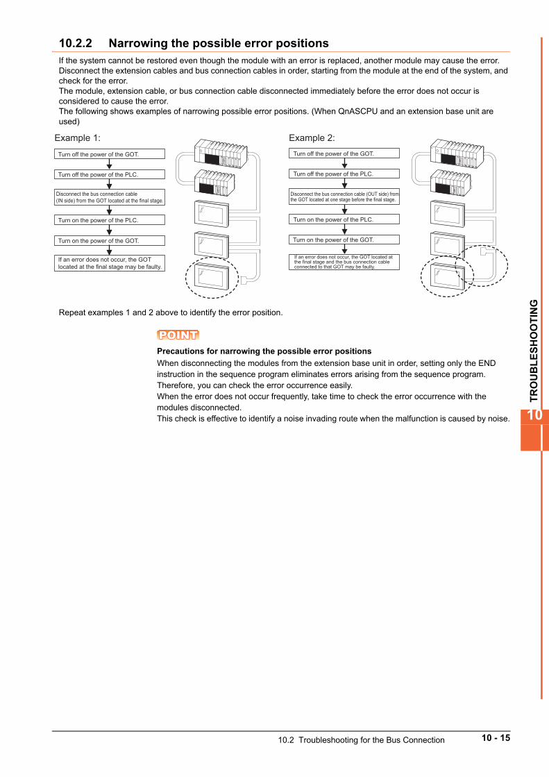
TR
OU
BL
ES
HO
OT
ING
10
10.2.2 Narrowing the possible error positionsIf the system cannot be restored even though the module with an error is replaced, another module may cause the error.Disconnect the extension cables and bus connection cables in order, starting from the module at the end of the system, and check for the error.The module, extension cable, or bus connection cable disconnected immediately before the error does not occur is considered to cause the error.The following shows examples of narrowing possible error positions. (When QnASCPU and an extension base unit are used)
Repeat examples 1 and 2 above to identify the error position.
POINTPOINTPOINTPrecautions for narrowing the possible error positions
When disconnecting the modules from the extension base unit in order, setting only the END instruction in the sequence program eliminates errors arising from the sequence program. Therefore, you can check the error occurrence easily.When the error does not occur frequently, take time to check the error occurrence with the modules disconnected.This check is effective to identify a noise invading route when the malfunction is caused by noise.
Turn off the power of the GOT.
Disconnect the bus connection cable (IN side) from the GOT located at the final stage.
If an error does not occur, the GOT located at the final stage may be faulty.
Example 1: Example 2:
Turn off the power of the PLC.
Turn on the power of the PLC.
Turn on the power of the GOT.
Turn off the power of the GOT.
Disconnect the bus connection cable (OUT side) from the GOT located at one stage before the final stage.
If an error does not occur, the GOT located at the final stage and the bus connection cable connected to that GOT may be faulty.
Turn off the power of the PLC.
Turn on the power of the PLC.
Turn on the power of the GOT.
10.2 Troubleshooting for the Bus Connection 10 - 15
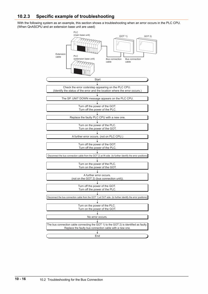
10.2.3 Specific example of troubleshootingWith the following system as an example, this section shows a troubleshooting when an error occurs in the PLC CPU. (When QnASCPU and an extension base unit are used)
PLC(main base unit) GOT 1) GOT 2)
PLC (extension base unit) Bus connection
cableBus connection cable
Extension cable
Start
Check the error code/step appearing on the PLC CPU. (Identify the status of the error and the location where the error occurs.)
Disconnect the bus connection cable from the GOT 2) at IN side. (to further identify the error positions)
The SP. UNIT DOWN message appears on the PLC CPU.
Turn off the power of the GOT. Turn off the power of the PLC.
Replace the faulty PLC CPU with a new one.
Turn on the power of the PLC. Turn on the power of the GOT.
A further error occurs. (not on PLC CPU.)
Turn off the power of the GOT. Turn off the power of the PLC.
Turn on the power of the PLC. Turn on the power of the GOT.
A further error occurs. (not on the GOT 2) (bus connection unit)).
Turn off the power of the GOT. Turn off the power of the PLC.
Disconnect the bus connection cable from the GOT 1) at OUT side. (to further identify the error positions)
Turn on the power of the PLC. Turn on the power of the GOT.
No error occurs.
The bus connection cable connecting the GOT 1) to the GOT 2) is identified as faulty. Replace the faulty bus connection cable with a new one.
End
10 - 16 10.2 Troubleshooting for the Bus Connection
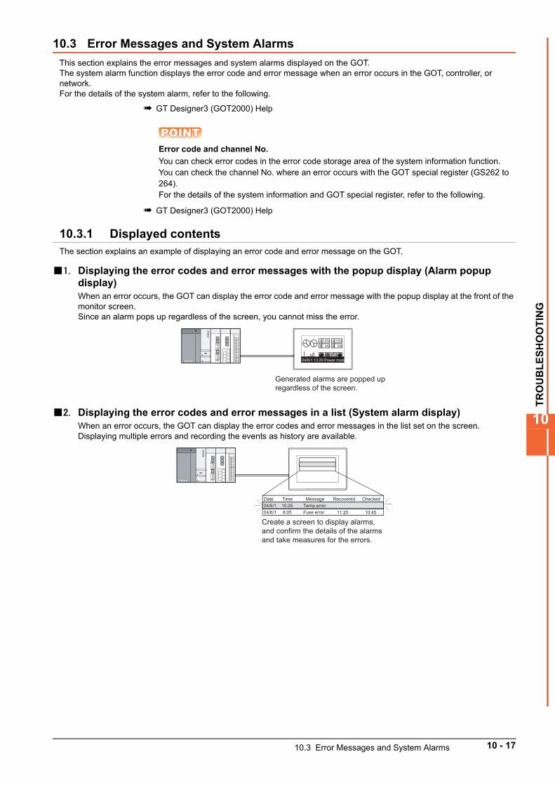
TR
OU
BL
ES
HO
OT
ING
10
10.3 Error Messages and System Alarms
This section explains the error messages and system alarms displayed on the GOT.The system alarm function displays the error code and error message when an error occurs in the GOT, controller, or network.For the details of the system alarm, refer to the following.
GT Designer3 (GOT2000) Help
POINTPOINTPOINTError code and channel No.
You can check error codes in the error code storage area of the system information function.You can check the channel No. where an error occurs with the GOT special register (GS262 to 264). For the details of the system information and GOT special register, refer to the following.
GT Designer3 (GOT2000) Help
10.3.1 Displayed contentsThe section explains an example of displaying an error code and error message on the GOT.
1. Displaying the error codes and error messages with the popup display (Alarm popup display)When an error occurs, the GOT can display the error code and error message with the popup display at the front of the monitor screen.Since an alarm pops up regardless of the screen, you cannot miss the error.
2. Displaying the error codes and error messages in a list (System alarm display)When an error occurs, the GOT can display the error codes and error messages in the list set on the screen.Displaying multiple errors and recording the events as history are available.
A 1254
348BA 1254
348B
04/6/1 13:20 Power module
Generated alarms are popped up regardless of the screen.
04/6/1 8:05 Fuse error
Date Time Message Recovered Checked04/6/1 10:25 Temp.error
Create a screen to display alarms, and confirm the details of the alarms and take measures for the errors.
11:25 10:45
10.3 Error Messages and System Alarms 10 - 17
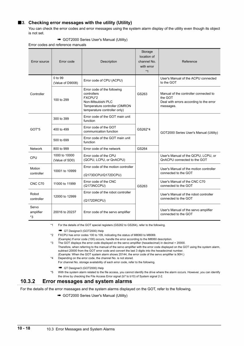
3. Checking error messages with the utility (Utility)You can check the error codes and error messages using the system alarm display of the utility even though its object is not set.
GOT2000 Series User's Manual (Utility)Error codes and reference manuals
*1 For the details of the GOT special registers (GS262 to GS264), refer to the following.
GT Designer3 (GOT2000) Help
*2 FXCPU has error codes 100 to 109, indicating the status of M8060 to M8069.
(Example) If error code (100) occurs, handle the error according to the M8060 description.*3 The GOT displays the error code displayed on the servo amplifier (hexadecimal) in decimal + 20000.
Therefore, when referring to the manual of the servo amplifier with the error code displayed on the GOT using the system alarm, subtract 20000 from the GOT error code and convert the last 3 digits into the hexadecimal number.(Example: When the GOT system alarm shows 20144, the error code of the servo amplifier is 90H.)
*4 Depending on the error code, the channel No. is not stored.
For channel No. storage availability of each error code, refer to the following.
GT Designer3 (GOT2000) Help
*5 With the system alarm related to the file access, you cannot identify the drive where the alarm occurs. However, you can identify
the drive by checking the File Access Error signal (b7 to b10) of System signal 2-2.
10.3.2 Error messages and system alarmsFor the details of the error massages and the system alarms displayed on the GOT, refer to the following.
GOT2000 Series User's Manual (Utility)
Error source Error code Description
Storage
location of
channel No.
with error
*1
Reference
Controller
0 to 99
(Value of D9008)Error code of CPU (ACPU)
GS263
User's Manual of the ACPU connected to the GOT
100 to 299
Error code of the following controllersFXCPU*2Non-Mitsubishi PLCTemperature controller (OMRON temperature controller only)
Manual of the controller connected to the GOTDeal with errors according to the error messages.
GOT*5
300 to 399Error code of the GOT main unit function
GS262*4GOT2000 Series User's Manual (Utility)
400 to 499Error code of the GOT communication function
500 to 699Error code of the GOT main unit function
Network 800 to 999 Error code of the network GS264
CPU1000 to 10000
(Value of SD0)Error code of the CPU(QCPU, LCPU, or QnACPU)
GS263
User's Manual of the QCPU, LCPU, or QnACPU connected to the GOT
Motion
controller10001 to 10999
Error code of the motion controller
(Q173DCPU/Q172DCPU)
User's Manual of the motion controller connected to the GOT
CNC C70 11000 to 11999Error code of the CNC(Q173NCCPU)
User's Manual of the CNC C70 connected to the GOT
Robot
controller12000 to 12999
Error code of the robot controller
(Q172DRCPU)
User's Manual of the robot controller connected to the GOT
Servo
amplifier
*3
20016 to 20237 Error code of the servo amplifierUser's Manual of the servo amplifier connected to the GOT
10 - 18 10.3 Error Messages and System Alarms
AP
PE
ND
ICE
S
11
11. APPENDICES
11.1 External Dimension Diagrams. . . . . . . . . . . . . . . . . . . . . . . . . . 11 - 2
11.2 Confirming of Versions and Conforming Standards. . . . . . . 11 - 15
11.3 Transportation Precautions . . . . . . . . . . . . . . . . . . . . . . . . . . . 11 - 15
11 - 1
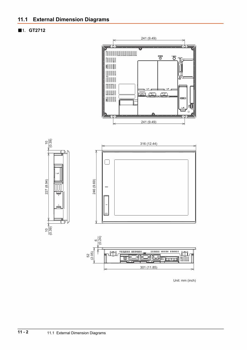
11.1 External Dimension Diagrams
1. GT2712
316 (12.44)
246
(9.6
9)
227
(8.9
4)10
(0.3
9)
10(0
.39)
52(2
.05)
6(0
.24)
241 (9.49)
241 (9.49)
301 (11.85)
Unit: mm (inch)
11 - 2 11.1 External Dimension Diagrams
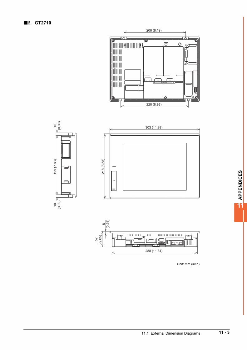
AP
PE
ND
ICE
S
11
2. GT2710
303 (11.93)
208 (8.19)
228 (8.98)
288 (11.34)
218
(8.5
8)
199
(7.8
3)10
(0.3
9)10
(0.3
9)
52(2
.05)
6(0
.24)
Unit: mm (inch)
11.1 External Dimension Diagrams 11 - 3
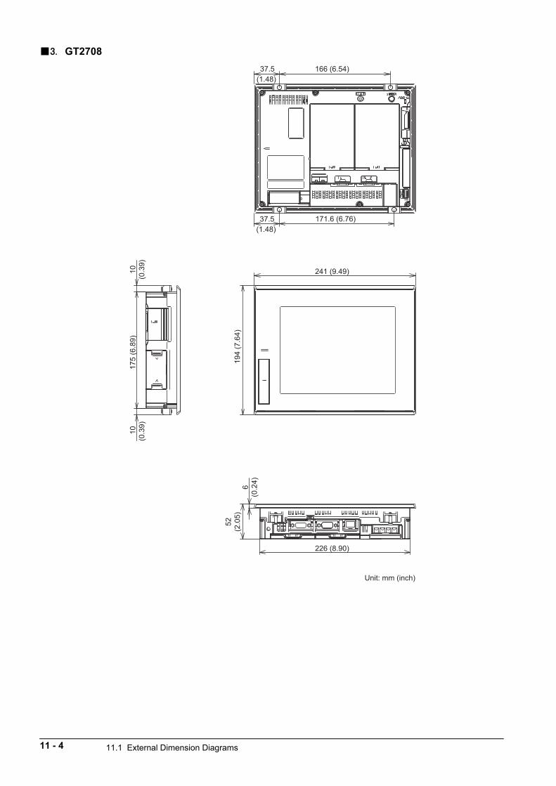
3. GT2708
241 (9.49)
166 (6.54)
226 (8.90)
171.6 (6.76) 37.5(1.48)
37.5(1.48)
175
(6.8
9)
194
(7.6
4)
10(0
.39)
10(0
.39)
52(2
.05)
6(0
.24)
Unit: mm (inch)
11 - 4 11.1 External Dimension Diagrams
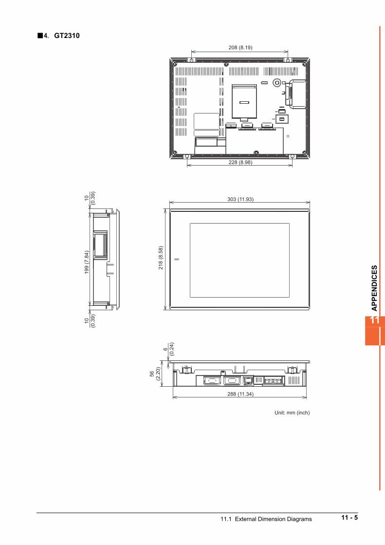
AP
PE
ND
ICE
S
11
4. GT2310
Unit: mm (inch)
303 (11.93)
208 (8.19)
228 (8.98)
288 (11.34)
218
(8.5
8)
199
(7.8
4)10
(0.3
9)10
(0.3
9)
56(2
.20)
6(0
.24)
11.1 External Dimension Diagrams 11 - 5
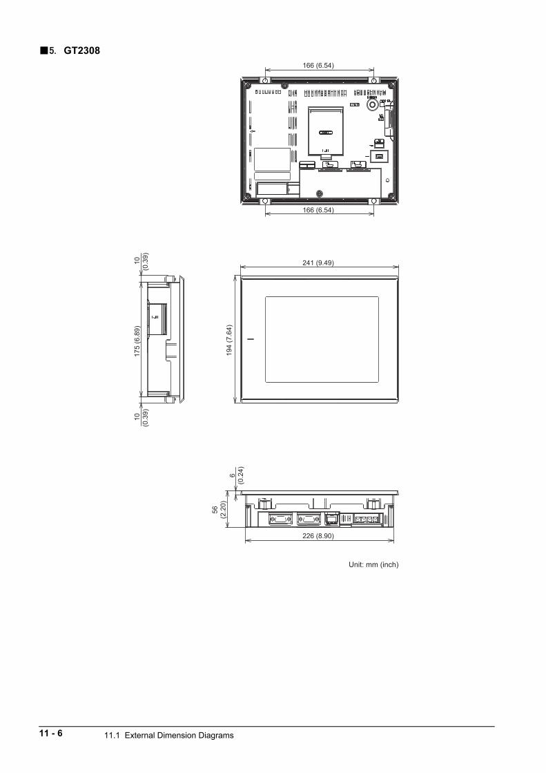
5. GT2308
Unit: mm (inch)
241 (9.49)
166 (6.54)
166 (6.54)
226 (8.90)
194
(7.6
4)
175
(6.8
9)10
(0.3
9)
10(0
.39)
56(2
.20)
6(0
.24)
11 - 6 11.1 External Dimension Diagrams
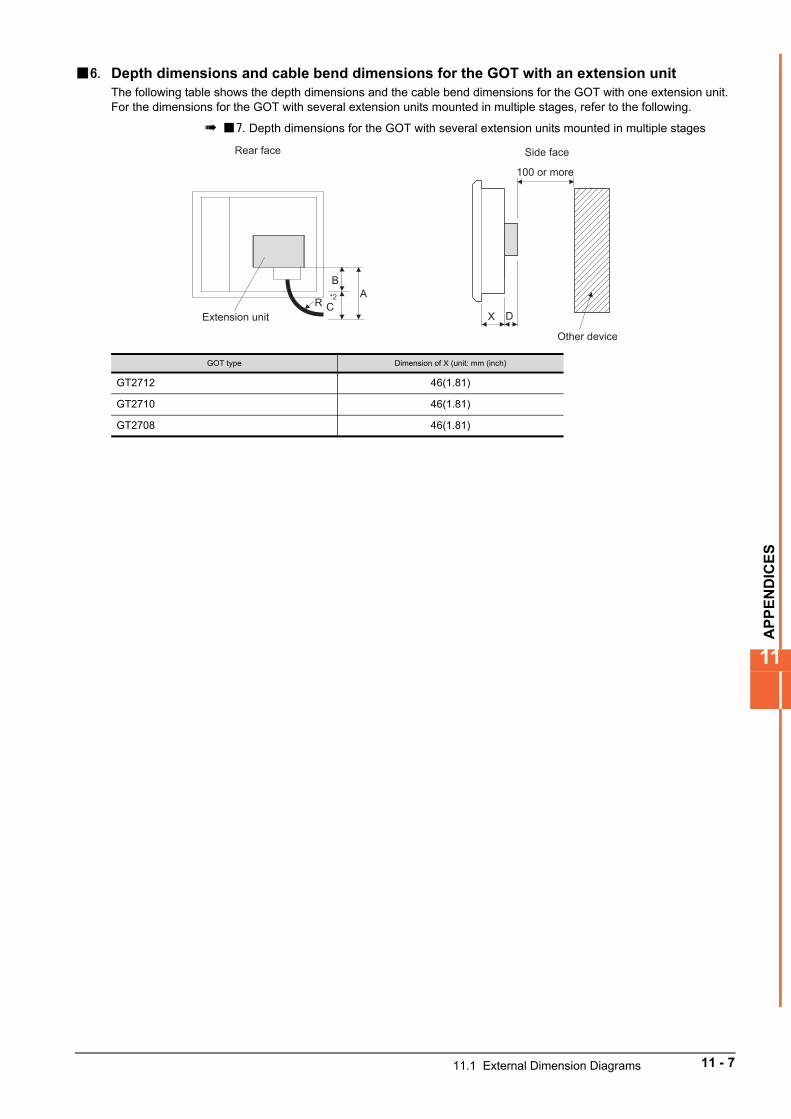
AP
PE
ND
ICE
S
11
6. Depth dimensions and cable bend dimensions for the GOT with an extension unitThe following table shows the depth dimensions and the cable bend dimensions for the GOT with one extension unit.For the dimensions for the GOT with several extension units mounted in multiple stages, refer to the following.
7. Depth dimensions for the GOT with several extension units mounted in multiple stages
GOT type Dimension of X (unit: mm (inch)
GT2712 46(1.81)
GT2710 46(1.81)
GT2708 46(1.81)
100 or more
X D
Other device
BA
CR *2
Extension unit
Rear face Side face
11.1 External Dimension Diagrams 11 - 7
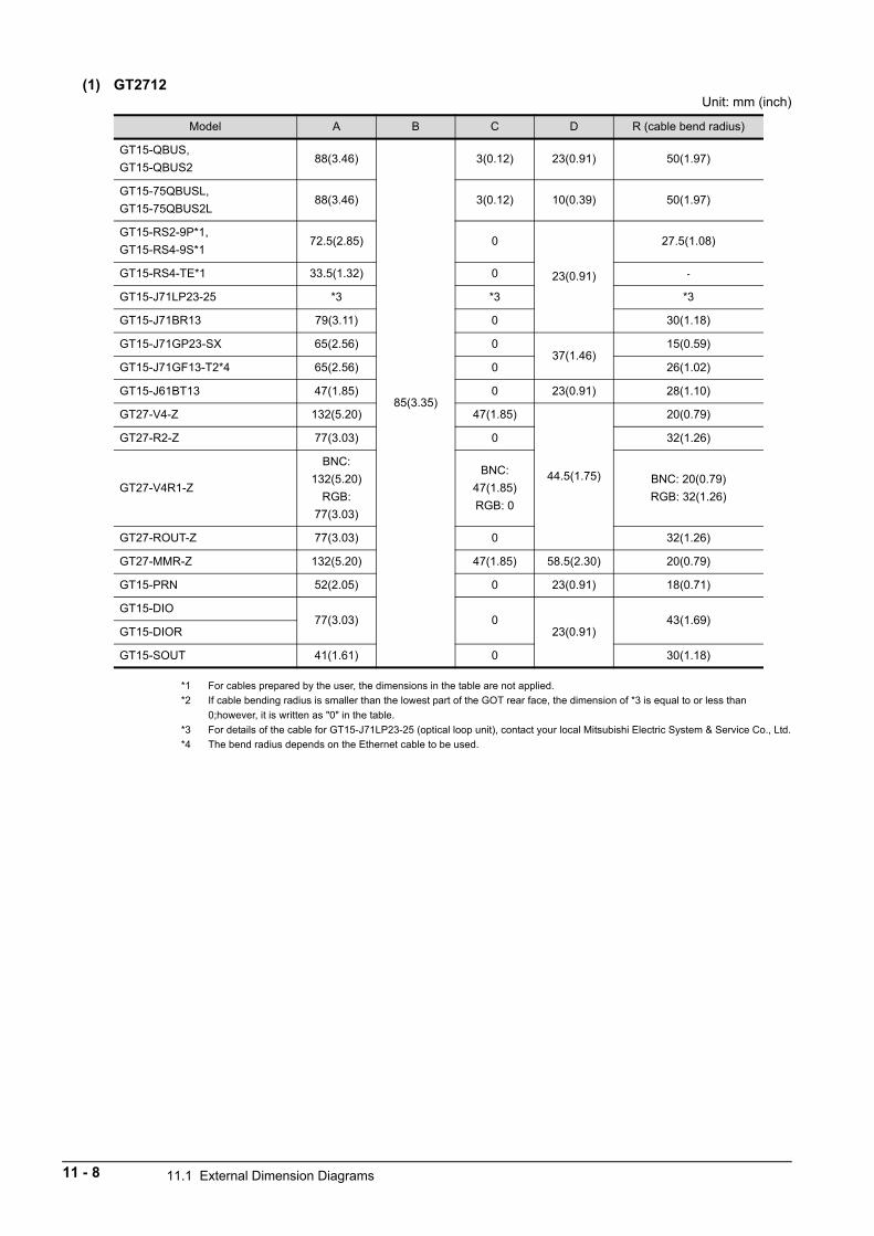
(1) GT2712Unit: mm (inch)
*1 For cables prepared by the user, the dimensions in the table are not applied.
*2 If cable bending radius is smaller than the lowest part of the GOT rear face, the dimension of *3 is equal to or less than
0;however, it is written as "0" in the table.
*3 For details of the cable for GT15-J71LP23-25 (optical loop unit), contact your local Mitsubishi Electric System & Service Co., Ltd.
*4 The bend radius depends on the Ethernet cable to be used.
Model A B C D R (cable bend radius)
GT15-QBUS,
GT15-QBUS288(3.46)
85(3.35)
3(0.12) 23(0.91) 50(1.97)
GT15-75QBUSL,
GT15-75QBUS2L88(3.46) 3(0.12) 10(0.39) 50(1.97)
GT15-RS2-9P*1,
GT15-RS4-9S*172.5(2.85) 0
23(0.91)
27.5(1.08)
GT15-RS4-TE*1 33.5(1.32) 0 -
GT15-J71LP23-25 *3 *3 *3
GT15-J71BR13 79(3.11) 0 30(1.18)
GT15-J71GP23-SX 65(2.56) 037(1.46)
15(0.59)
GT15-J71GF13-T2*4 65(2.56) 0 26(1.02)
GT15-J61BT13 47(1.85) 0 23(0.91) 28(1.10)
GT27-V4-Z 132(5.20) 47(1.85)
44.5(1.75)
20(0.79)
GT27-R2-Z 77(3.03) 0 32(1.26)
GT27-V4R1-Z
BNC:
132(5.20)
RGB:
77(3.03)
BNC:
47(1.85)
RGB: 0
BNC: 20(0.79)
RGB: 32(1.26)
GT27-ROUT-Z 77(3.03) 0 32(1.26)
GT27-MMR-Z 132(5.20) 47(1.85) 58.5(2.30) 20(0.79)
GT15-PRN 52(2.05) 0 23(0.91) 18(0.71)
GT15-DIO77(3.03) 0
23(0.91)43(1.69)
GT15-DIOR
GT15-SOUT 41(1.61) 0 30(1.18)
11 - 8 11.1 External Dimension Diagrams
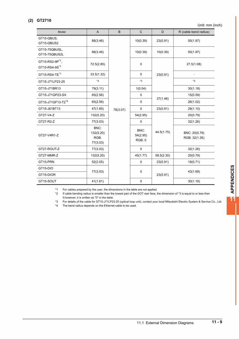
AP
PE
ND
ICE
S
11
(2) GT2710Unit: mm (inch)
*1 For cables prepared by the user, the dimensions in the table are not applied.
*2 If cable bending radius is smaller than the lowest part of the GOT rear face, the dimension of *3 is equal to or less than
0;however, it is written as "0" in the table.
*3 For details of the cable for GT15-J71LP23-25 (optical loop unit), contact your local Mitsubishi Electric System & Service Co., Ltd.
*4 The bend radius depends on the Ethernet cable to be used.
Model A B C D R (cable bend radius)
GT15-QBUS,
GT15-QBUS288(3.46)
78(3.07)
10(0.39) 23(0.91) 50(1.97)
GT15-75QBUSL,
GT15-75QBUS2L88(3.46) 10(0.39) 10(0.39) 50(1.97)
GT15-RS2-9P*1,
GT15-RS4-9S*172.5(2.85) 0
23(0.91)
27.5(1.08)
GT15-RS4-TE*1 33.5(1.32) 0 -
GT15-J71LP23-25 *3 *3 *3
GT15-J71BR13 79(3.11) 1(0.04) 30(1.18)
GT15-J71GP23-SX 65(2.56) 037(1.46)
15(0.59)
GT15-J71GF13-T2*4 65(2.56) 0 26(1.02)
GT15-J61BT13 47(1.85) 0 23(0.91) 28(1.10)
GT27-V4-Z 132(5.20) 54(2.95)
44.5(1.75)
20(0.79)
GT27-R2-Z 77(3.03) 0 32(1.26)
GT27-V4R1-Z
BNC:
132(5.20)
RGB:
77(3.03)
BNC:
54(2.95)
RGB: 0
BNC: 20(0.79)
RGB: 32(1.26)
GT27-ROUT-Z 77(3.03) 0 32(1.26)
GT27-MMR-Z 132(5.20) 45(1.77) 58.5(2.30) 20(0.79)
GT15-PRN 52(2.05) 0 23(0.91) 18(0.71)
GT15-DIO77(3.03) 0
23(0.91)43(1.69)
GT15-DIOR
GT15-SOUT 41(1.61) 0 30(1.18)
11.1 External Dimension Diagrams 11 - 9
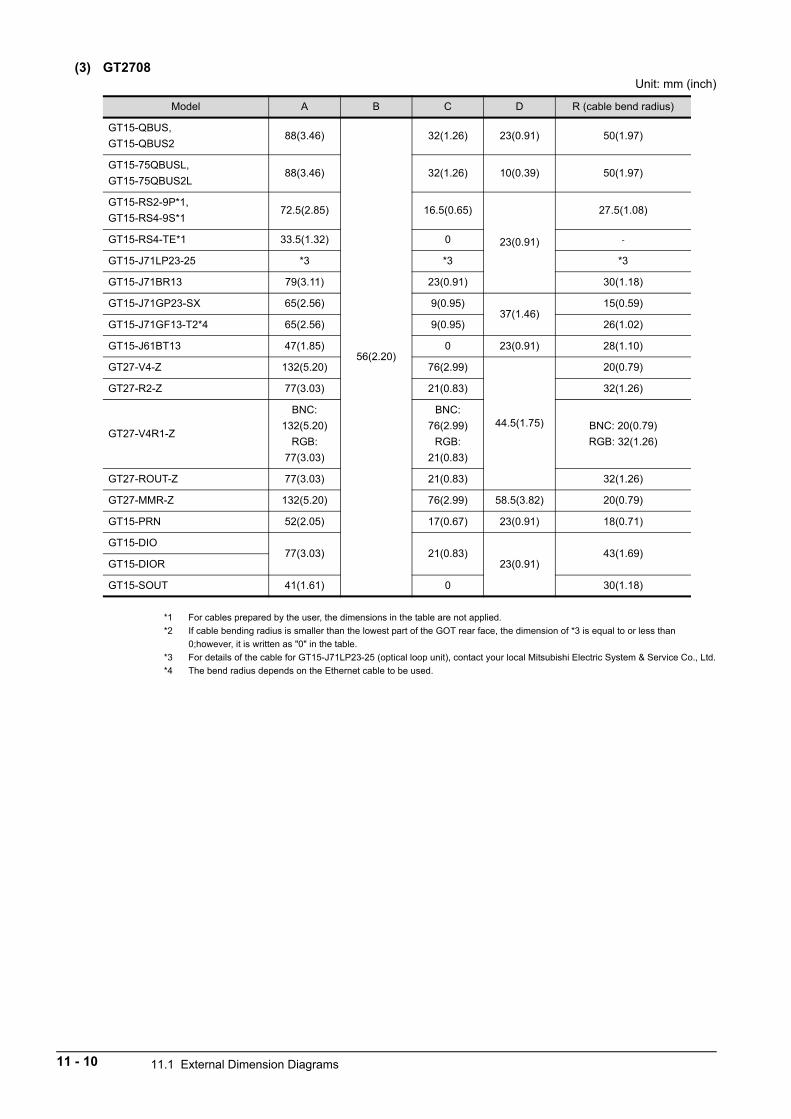
(3) GT2708Unit: mm (inch)
*1 For cables prepared by the user, the dimensions in the table are not applied.
*2 If cable bending radius is smaller than the lowest part of the GOT rear face, the dimension of *3 is equal to or less than
0;however, it is written as "0" in the table.
*3 For details of the cable for GT15-J71LP23-25 (optical loop unit), contact your local Mitsubishi Electric System & Service Co., Ltd.
*4 The bend radius depends on the Ethernet cable to be used.
Model A B C D R (cable bend radius)
GT15-QBUS,
GT15-QBUS288(3.46)
56(2.20)
32(1.26) 23(0.91) 50(1.97)
GT15-75QBUSL,
GT15-75QBUS2L88(3.46) 32(1.26) 10(0.39) 50(1.97)
GT15-RS2-9P*1,
GT15-RS4-9S*172.5(2.85) 16.5(0.65)
23(0.91)
27.5(1.08)
GT15-RS4-TE*1 33.5(1.32) 0 -
GT15-J71LP23-25 *3 *3 *3
GT15-J71BR13 79(3.11) 23(0.91) 30(1.18)
GT15-J71GP23-SX 65(2.56) 9(0.95)37(1.46)
15(0.59)
GT15-J71GF13-T2*4 65(2.56) 9(0.95) 26(1.02)
GT15-J61BT13 47(1.85) 0 23(0.91) 28(1.10)
GT27-V4-Z 132(5.20) 76(2.99)
44.5(1.75)
20(0.79)
GT27-R2-Z 77(3.03) 21(0.83) 32(1.26)
GT27-V4R1-Z
BNC:
132(5.20)
RGB:
77(3.03)
BNC:
76(2.99)
RGB:
21(0.83)
BNC: 20(0.79)
RGB: 32(1.26)
GT27-ROUT-Z 77(3.03) 21(0.83) 32(1.26)
GT27-MMR-Z 132(5.20) 76(2.99) 58.5(3.82) 20(0.79)
GT15-PRN 52(2.05) 17(0.67) 23(0.91) 18(0.71)
GT15-DIO77(3.03) 21(0.83)
23(0.91)43(1.69)
GT15-DIOR
GT15-SOUT 41(1.61) 0 30(1.18)
11 - 10 11.1 External Dimension Diagrams
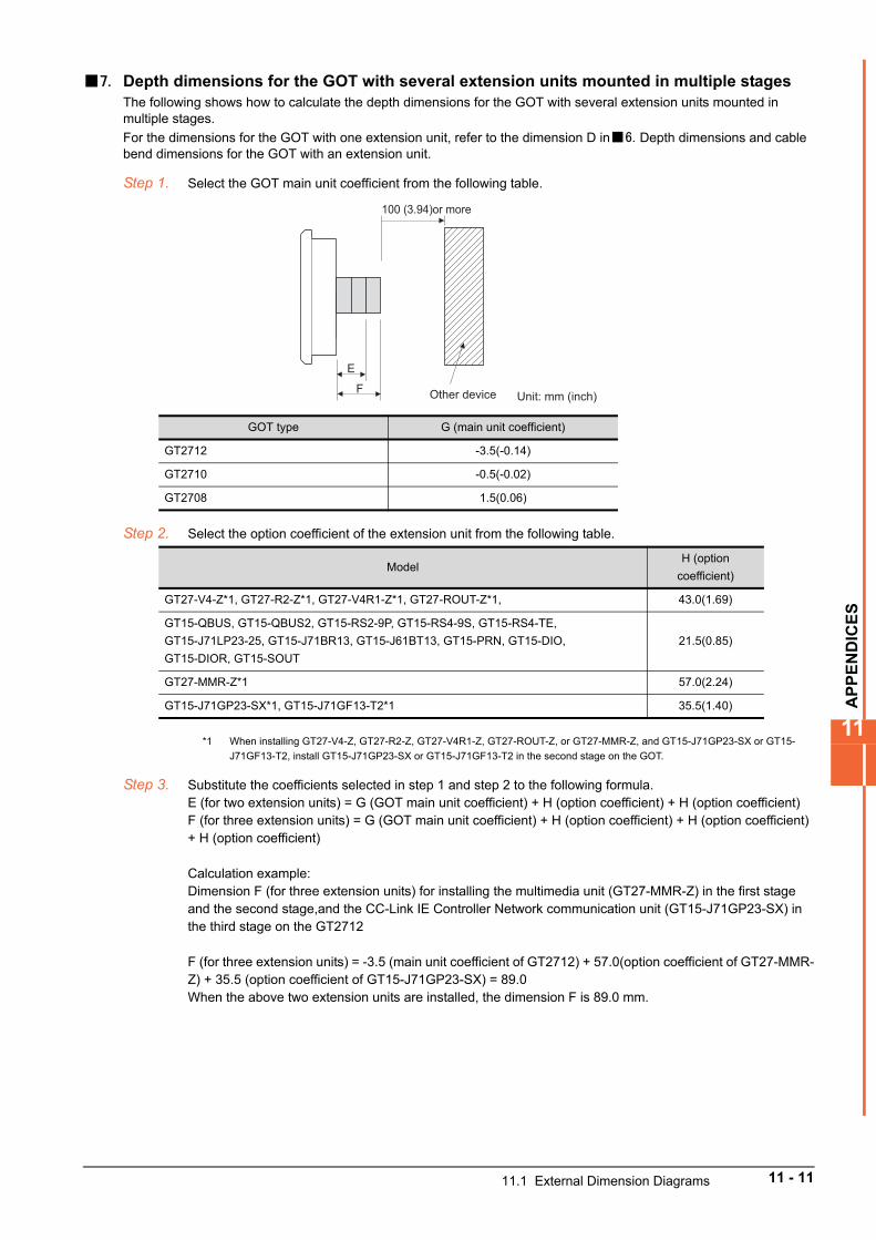
AP
PE
ND
ICE
S
11
7. Depth dimensions for the GOT with several extension units mounted in multiple stagesThe following shows how to calculate the depth dimensions for the GOT with several extension units mounted in multiple stages.
For the dimensions for the GOT with one extension unit, refer to the dimension D in6. Depth dimensions and cable bend dimensions for the GOT with an extension unit.
Step 1. Select the GOT main unit coefficient from the following table.
Step 2. Select the option coefficient of the extension unit from the following table.
*1 When installing GT27-V4-Z, GT27-R2-Z, GT27-V4R1-Z, GT27-ROUT-Z, or GT27-MMR-Z, and GT15-J71GP23-SX or GT15-
J71GF13-T2, install GT15-J71GP23-SX or GT15-J71GF13-T2 in the second stage on the GOT.
Step 3. Substitute the coefficients selected in step 1 and step 2 to the following formula.E (for two extension units) = G (GOT main unit coefficient) + H (option coefficient) + H (option coefficient)F (for three extension units) = G (GOT main unit coefficient) + H (option coefficient) + H (option coefficient) + H (option coefficient)
Calculation example:Dimension F (for three extension units) for installing the multimedia unit (GT27-MMR-Z) in the first stage and the second stage,and the CC-Link IE Controller Network communication unit (GT15-J71GP23-SX) in the third stage on the GT2712
F (for three extension units) = -3.5 (main unit coefficient of GT2712) + 57.0(option coefficient of GT27-MMR-Z) + 35.5 (option coefficient of GT15-J71GP23-SX) = 89.0When the above two extension units are installed, the dimension F is 89.0 mm.
GOT type G (main unit coefficient)
GT2712 -3.5(-0.14)
GT2710 -0.5(-0.02)
GT2708 1.5(0.06)
ModelH (option
coefficient)
GT27-V4-Z*1, GT27-R2-Z*1, GT27-V4R1-Z*1, GT27-ROUT-Z*1, 43.0(1.69)
GT15-QBUS, GT15-QBUS2, GT15-RS2-9P, GT15-RS4-9S, GT15-RS4-TE,
GT15-J71LP23-25, GT15-J71BR13, GT15-J61BT13, GT15-PRN, GT15-DIO,
GT15-DIOR, GT15-SOUT
21.5(0.85)
GT27-MMR-Z*1 57.0(2.24)
GT15-J71GP23-SX*1, GT15-J71GF13-T2*1 35.5(1.40)
Other device
100 (3.94)or more
Unit: mm (inch)
E
F
11.1 External Dimension Diagrams 11 - 11
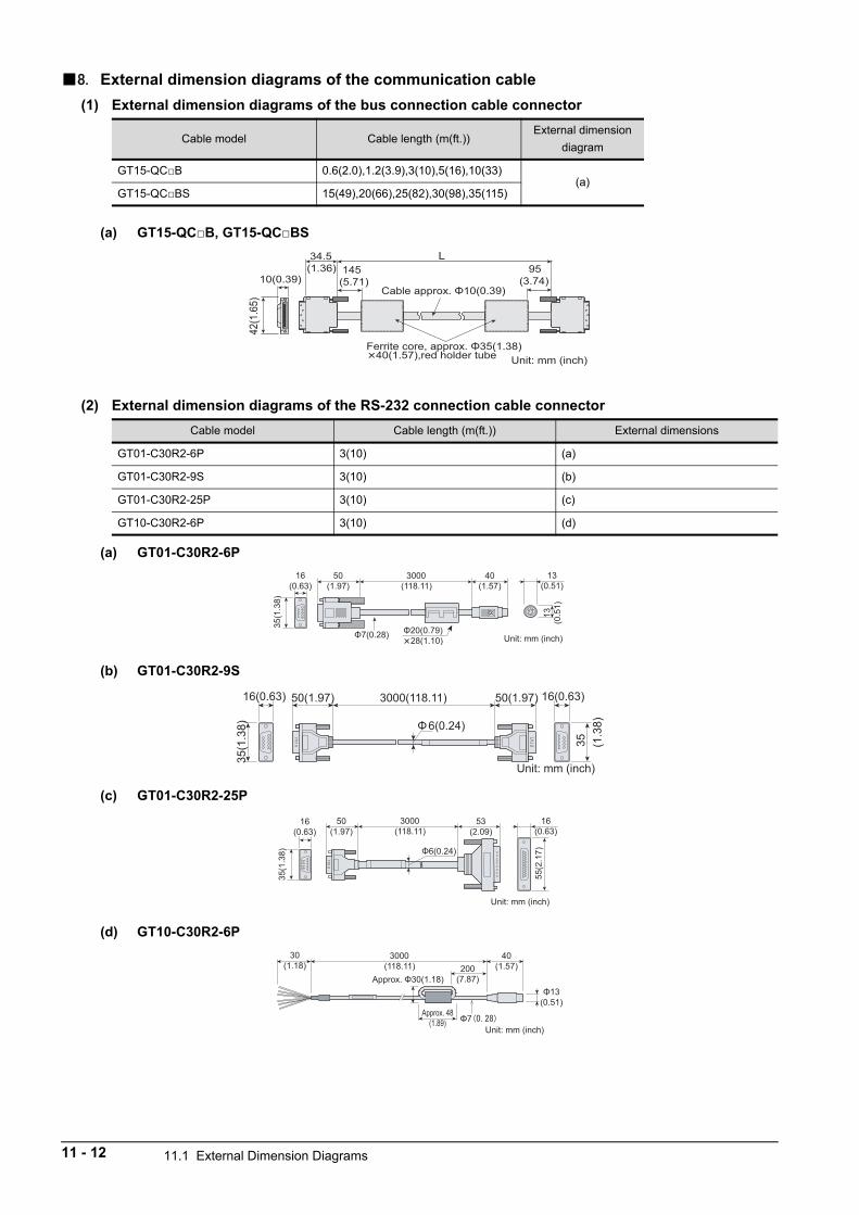
8. External dimension diagrams of the communication cable
(1) External dimension diagrams of the bus connection cable connector
(a) GT15-QCB, GT15-QCBS
(2) External dimension diagrams of the RS-232 connection cable connector
(a) GT01-C30R2-6P
(b) GT01-C30R2-9S
(c) GT01-C30R2-25P
(d) GT10-C30R2-6P
Cable model Cable length (m(ft.))External dimension
diagram
GT15-QCB 0.6(2.0),1.2(3.9),3(10),5(16),10(33)(a)
GT15-QCBS 15(49),20(66),25(82),30(98),35(115)
Cable model Cable length (m(ft.)) External dimensions
GT01-C30R2-6P 3(10) (a)
GT01-C30R2-9S 3(10) (b)
GT01-C30R2-25P 3(10) (c)
GT10-C30R2-6P 3(10) (d)
145(5.71)
L 95(3.74)10(0.39)
Unit: mm (inch)
42(1
.65)
34.5(1.36)
50(1.97)
40(1.57)
13(0.51)
3000(118.11)
35(1
.38)
16(0.63)
13(0
.51)
Unit: mm (inch)
16(0.63) 50(1.97) 50(1.97)3000(118.11)
35(1
.38)
16(0.63)
35
Φ6(0.24)
Unit: mm (inch)
(1.3
8)
3000(118.11)
50(1.97)
16(0.63)
35(1
.38)
53(2.09)
55(2
.17)
16(0.63)
Unit: mm (inch)
3000(118.11)
Unit: mm (inch)
40(1.57)200
(7.87)
Approx. 48(1.89)
30(1.18)
11 - 12 11.1 External Dimension Diagrams
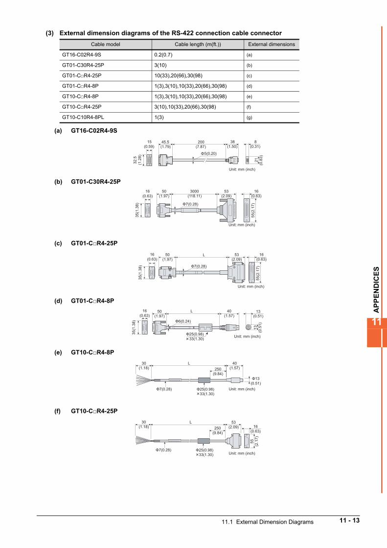
AP
PE
ND
ICE
S
11
(3) External dimension diagrams of the RS-422 connection cable connector
(a) GT16-C02R4-9S
(b) GT01-C30R4-25P
(c) GT01-CR4-25P
(d) GT01-CR4-8P
(e) GT10-CR4-8P
(f) GT10-CR4-25P
Cable model Cable length (m(ft.)) External dimensions
GT16-C02R4-9S 0.2(0.7) (a)
GT01-C30R4-25P 3(10) (b)
GT01-CR4-25P 10(33),20(66),30(98) (c)
GT01-CR4-8P 1(3),3(10),10(33),20(66),30(98) (d)
GT10-CR4-8P 1(3),3(10),10(33),20(66),30(98) (e)
GT10-CR4-25P 3(10),10(33),20(66),30(98) (f)
GT10-C10R4-8PL 1(3) (g)
15(0.59)
8(0.31)
45.5(1.79)
38(1.50)
200(7.87)
32.
5(1
.28)
21
(0.8
3)
5(0.20)
Unit: mm (inch)
50(1.97)
16(0.63)
Unit: mm (inch)
35(1
.38)
53(2.09)
55(2
.17)
3000(118.11)
16(0.63)
LFig.13 50(1.97)
16(0.63)
35(1
.38)
53(2.09)
55(2
.17)
16(0.63)
Unit: mm (inch)
40(1.57)
13(0.51)
13(0
.51)
L50(1.97)
16(0.63)
35(1
.38)
Unit: mm (inch)
30(1.18)
L 40(1.57)250
(9.84)
Unit: mm (inch)
53(2.09)
55(2
.17)
16(0.63)
30(1.18)
L250
(9.84)
Unit: mm (inch)
11.1 External Dimension Diagrams 11 - 13
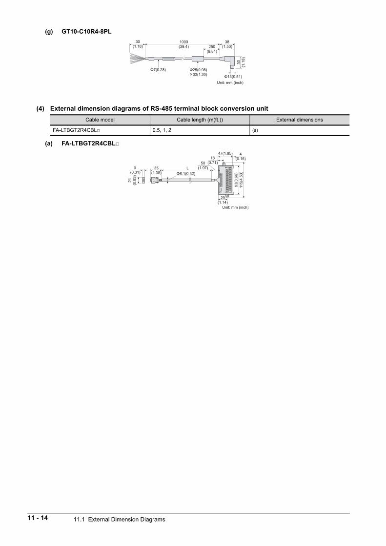
(g) GT10-C10R4-8PL
(4) External dimension diagrams of RS-485 terminal block conversion unit
(a) FA-LTBGT2R4CBL
Cable model Cable length (m(ft.)) External dimensions
FA-LTBGT2R4CBL 0.5, 1, 2 (a)
1000(39.4)
38(1.50)
30(1
.18)
30(1.18) 250
(9.84)
Unit: mm (inch)
50(1.97)
47(1.85)18
(0.71)
4(0.16)
29(1.14)
115(
4.53
)
35(1.38)
93(3
.66)
21(0
.83)
8(0.31)
L
Unit: mm (inch)
11 - 14 11.1 External Dimension Diagrams
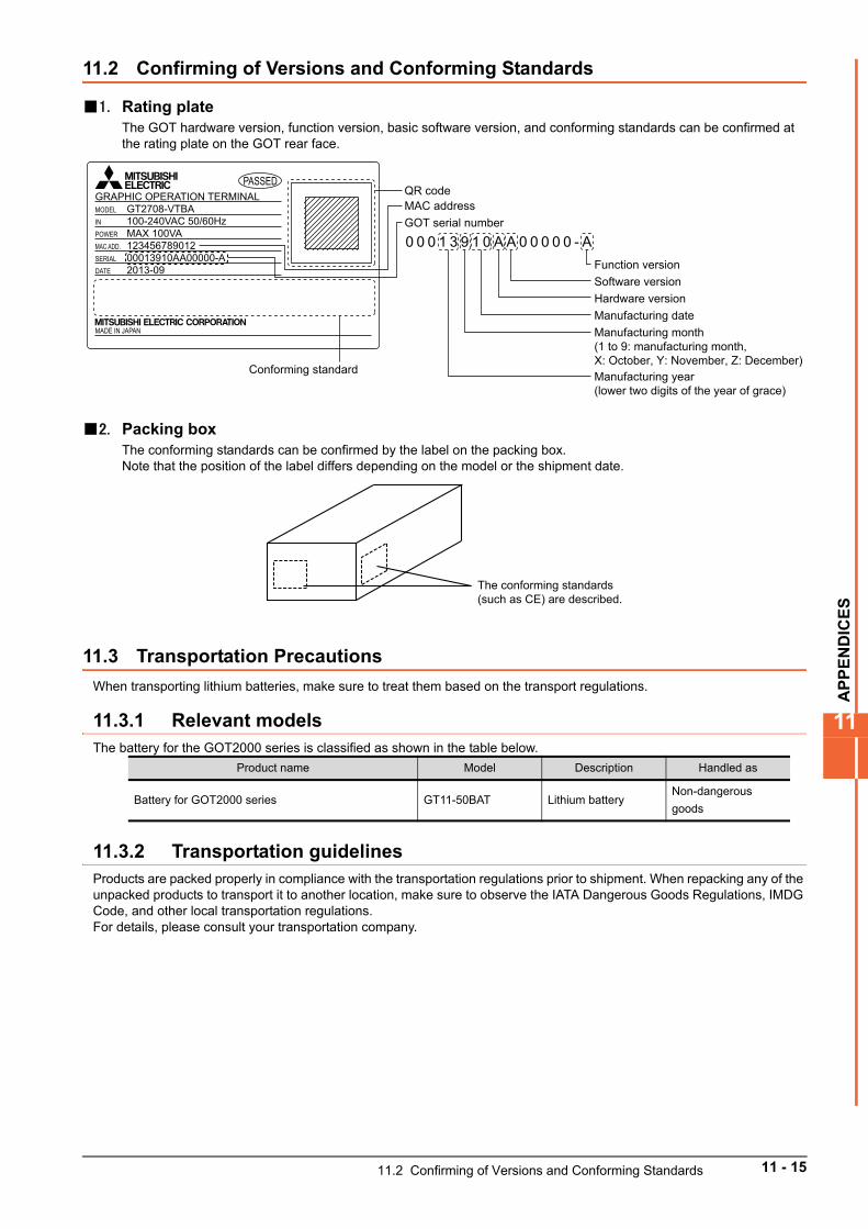
AP
PE
ND
ICE
S
11
11.2 Confirming of Versions and Conforming Standards
1. Rating plateThe GOT hardware version, function version, basic software version, and conforming standards can be confirmed at the rating plate on the GOT rear face.
2. Packing boxThe conforming standards can be confirmed by the label on the packing box.Note that the position of the label differs depending on the model or the shipment date.
11.3 Transportation Precautions
When transporting lithium batteries, make sure to treat them based on the transport regulations.
11.3.1 Relevant modelsThe battery for the GOT2000 series is classified as shown in the table below.
11.3.2 Transportation guidelinesProducts are packed properly in compliance with the transportation regulations prior to shipment. When repacking any of the unpacked products to transport it to another location, make sure to observe the IATA Dangerous Goods Regulations, IMDG Code, and other local transportation regulations.For details, please consult your transportation company.
Product name Model Description Handled as
Battery for GOT2000 series GT11-50BAT Lithium batteryNon-dangerous
goods
QR code
Conforming standard
MAC addressGOT serial number
Function versionSoftware versionHardware versionManufacturing date
Manufacturing year (lower two digits of the year of grace)
Manufacturing month (1 to 9: manufacturing month, X: October, Y: November, Z: December)
MODEL
DATE
MADE IN JAPAN
SERIALMAC ADD. 123456789012POWER
GRAPHIC OPERATION TERMINALPASSED
INGT2708-VTBA
2013-0900013910AA00000-A
MAX 100VA100-240VAC 50/60Hz
0 0 0 1 3 9 1 0 A A 0 0 0 0 0 - A
The conforming standards (such as CE) are described.
11.2 Confirming of Versions and Conforming Standards 11 - 15

11 - 16 11.3 Transportation Precautions
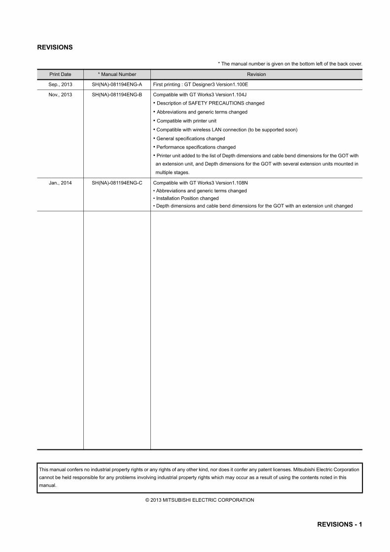
REVISIONS
* The manual number is given on the bottom left of the back cover.
© 2013 MITSUBISHI ELECTRIC CORPORATION
Print Date * Manual Number Revision
Sep., 2013 SH(NA)-081194ENG-A First printing : GT Designer3 Version1.100E
Nov., 2013 SH(NA)-081194ENG-B Compatible with GT Works3 Version1.104J
• Description of SAFETY PRECAUTIONS changed
• Abbreviations and generic terms changed
• Compatible with printer unit
• Compatible with wireless LAN connection (to be supported soon)
• General specifications changed
• Performance specifications changed
• Printer unit added to the list of Depth dimensions and cable bend dimensions for the GOT with
an extension unit, and Depth dimensions for the GOT with several extension units mounted in
multiple stages.
Jan., 2014 SH(NA)-081194ENG-C Compatible with GT Works3 Version1.108N
• Abbreviations and generic terms changed
• Installation Position changed
• Depth dimensions and cable bend dimensions for the GOT with an extension unit changed
This manual confers no industrial property rights or any rights of any other kind, nor does it confer any patent licenses. Mitsubishi Electric Corporation
cannot be held responsible for any problems involving industrial property rights which may occur as a result of using the contents noted in this
manual.
REVISIONS - 1

REVISIONS - 2
WARRANTYPlease confirm the following product warranty details before using this product.
1. Gratis Warranty Term and Gratis Warranty RangeIf any faults or defects (hereinafter "Failure") found to be the responsibility of Mitsubishi occurs during use of the product within the gratis warranty term, the product shall be repaired at no cost via the sales representative or Mitsubishi Service Company.However, if repairs are required onsite at domestic or overseas location, expenses to send an engineer will be solely at the customer's discretion. Mitsubishi shall not be held responsible for any re-commissioning, maintenance, or testing on-site that involves replacement of the failed module.[Gratis Warranty Term]
The gratis warranty term of the product shall be for thirty-six (36) months after the date of purchase or delivery to a designated place.Note that after manufacture and shipment from Mitsubishi, the maximum distribution period shall be six (6) months, and the longest gratis warranty term after manufacturing shall be forty-two (42) months. The gratis warranty term of repair parts shall not exceed the gratis warranty term before repairs.
[Gratis Warranty Range](1) The customer shall be responsible for the primary failure diagnosis unless otherwise specified. If requested by the customer, Mitsubishi Electric Corporation or its representative firm may carry out the primary failure
diagnosis at the customer’s expence. The primary failure diagnosis will, however, be free of charge should the cause of failure be attributable to Mitsubishi Electric
Corporation.(2) The range shall be limited to normal use within the usage state, usage methods and usage environment, etc., which follow
the conditions and precautions, etc., given in the instruction manual, user's manual and caution labels on the product.(3) Even within the gratis warranty term, repairs shall be charged for in the following cases.
1. Failure occurring from inappropriate storage or handling, carelessness or negligence by the user. Failure caused by the user's hardware or software design.
2. Failure caused by unapproved modifications, etc., to the product by the user.3. When the Mitsubishi product is assembled into a user's device, Failure that could have been avoided if functions or
structures, judged as necessary in the legal safety measures the user's device is subject to or as necessary by industry standards, had been provided.
4. Failure that could have been avoided if consumable parts designated in the instruction manual had been correctly serviced or replaced.
5. Replacing consumable parts such as the battery, backlight and fuses.6. Failure caused by external irresistible forces such as fires or abnormal voltages, and Failure caused by force majeure
such as earthquakes, lightning, wind and water damage.7. Failure caused by reasons unpredictable by scientific technology standards at time of shipment from Mitsubishi.8. Any other failure found not to be the responsibility of Mitsubishi or that admitted not to be so by the user.
2. Onerous repair term after discontinuation of production(1) Mitsubishi shall accept onerous product repairs for seven (7) years after production of the product is discontinued.
Discontinuation of production shall be notified with Mitsubishi Technical Bulletins, etc.(2) Product supply (including repair parts) is not available after production is discontinued.
3. Overseas serviceOverseas, repairs shall be accepted by Mitsubishi's local overseas FA Center. Note that the repair conditions at each FA Center may differ.
4. Exclusion of loss in opportunity and secondary loss from warranty liabilityRegardless of the gratis warranty term, Mitsubishi shall not be liable for compensation to damages caused by any cause found not to be the responsibility of Mitsubishi, loss in opportunity, lost profits incurred to the user by Failures of Mitsubishi products, special damages and secondary damages whether foreseeable or not, compensation for accidents, and compensation for damages to products other than Mitsubishi products, replacement by the user, maintenance of on-site equipment, start-up test run and other tasks.
5. Changes in product specificationsThe specifications given in the catalogs, manuals or technical documents are subject to change without prior notice.
6. Product application(1) In using the Mitsubishi graphic operation terminal, the usage conditions shall be that the application will not lead to a major
accident even if any problem or fault should occur in the graphic operation terminal device, and that backup and fail-safe functions are systematically provided outside of the device for any problem or fault.
(2) The Mitsubishi graphic operation terminal has been designed and manufactured for applications in general industries, etc. Thus, applications in which the public could be affected such as in nuclear power plants and other power plants operated by respective power companies, and applications in which a special quality assurance system is required, such as for Railway companies or Public service purposes shall be excluded from the graphic operation terminal applications.In addition, applications in which human life or property that could be greatly affected, such as in aircraft, medical applications, incineration and fuel devices, manned transportation equipment for recreation and amusement, and safety devices, shall also be excluded from the graphic operation terminal range of applications.However, in certain cases, some applications may be possible, providing the user consults the local Mitsubishi representative outlining the special requirements of the project, and providing that all parties concerned agree to the special circumstances, solely at our discretion.
In some of three cases, however, Mitsubishi Electric Corporation may consider the possibility of an application, provided that the customer notifies Mitsubishi Electric Corporation of the intention, the application is clearly defined and any special quality is not required.

GOT is a registered trademark of Mitsubishi Electric Corporation.
Microsoft, Windows, Windows NT, Windows Server, Windows Vista, and Windows 7 are registered trademarks or trademarks
of Microsoft Corporation in the United States and other countries.
Adobe and Adobe Reader are registered trademarks of Adobe Systems Incorporated.
Pentium and Celeron are a registered trademarks of Intel Corporation in the United States and other countries.
Ethernet is a registered trademark of Xerox Corporation in the United States.
MODBUS is a trademark of Schneider Electric SA.
VNC is a registered trademark of RealVNC Ltd. in the United States and other countries.
Other company and product names herein are either trademarks or registered trademarks of their respective owners.
SH(NA)-081194ENG-C

MODEL
MODELCODE
GOT2000-U-HW-E
1D7MJ5
SH(NA)-081194ENG-C(1401)MEE
GOT2000 Series User's Manual (Hardware)
Specifications subject to change without notice. Printed in Japan, January 2014.
When exported from Japan, this manual does not require application to the Ministry of Economy, Trade and Industry for service transaction permission.
HEAD OFFICE : TOKYO BUILDING, 2-7-3 MARUNOUCHI, CHIYODA-KU, TOKYO 100-8310, JAPANNAGOYA WORKS : 1-14 , YADA-MINAMI 5-CHOME , HIGASHI-KU, NAGOYA , JAPAN