Embed Size (px)
Citation preview

BEST PRACTICEPROGRAMME
GOOD PRACTICE GUIDE 168
GO
OD
PRA
CT
ICE G
UID
E 168
Cutting your energy costs
A guide for the textile dyeing and finishing industry

THE UK TEXTILE DYEING AND FINISHING INDUSTRY
This booklet is No. 168 in the Good Practice Guide series and provides practical advice to thosewho operate in the textile industry on how to improve the efficiency of their very energyintensive dyeing and finishing processes. The main methods of dyeing and finishing arereviewed and their energy use analysed. A range of energy-saving ideas is presented for each,and both low-cost measures and those involving capital expenditure are discussed.
Prepared for the Department of the Environment by:
ETSUHarwellDidcotOxfordshireOX11 0RA

© Crown copyright 1997First published March 1997
Other titles in the Good Practice Guide Series1. GUIDANCE NOTES FOR THE IMPLEMENTATION OF SMALL-SCALE PACKAGED COMBINED HEAT AND POWER2. GUIDANCE NOTES FOR REDUCING ENERGY CONSUMPTION COSTS OF ELECTRIC MOTOR AND DRIVE SYSTEMS3. INTRODUCTION TO SMALL-SCALE COMBINED HEAT AND POWER13. WASTE HEAT RECOVERY FROM HIGH TEMPERATURE GAS STREAMS14. RETROFITTING AC VARIABLE SPEED DRIVES17. GUIDANCE NOTES FOR ACHIEVING HIGH YIELDS IN IRON FOUNDRIES18. REDUCING ENERGY CONSUMPTION COST BY STEAM METERING30. ENERGY EFFICIENT OPERATION OF INDUSTRIAL BOILER PLANT31. COMPUTER AIDED MONITORING AND TARGETING FOR INDUSTRY36. COMMERCIAL REFRIGERATION PLANT: ENERGY EFFICIENT OPERATION AND MAINTENANCE37. COMMERCIAL REFRIGERATION PLANT: ENERGY EFFICIENT DESIGN38. COMMERCIAL REFRIGERATION PLANT: ENERGY EFFICIENT INSTALLATION42. INDUSTRIAL REFRIGERATION PLANT: ENERGY EFFICIENT OPERATION AND MAINTENANCE43. INTRODUCTION TO LARGE-SCALE COMBINED HEAT AND POWER44. INDUSTRIAL REFRIGERATION PLANT: ENERGY EFFICIENT DESIGN47. RUBBER COMPOUNDING IN THE RUBBER PROCESSING INDUSTRY48. REDUCING ELECTRICITY USE IN INJECTION MOULDING49. ENERGY EFFICIENT LADLE PRE-HEATING TECHNIQUES WITHIN THE STEEL INDUSTRY50. GUIDANCE NOTES FOR THE EFFICIENT OPERATION OF CORELESS INDUCTION FURNACES58. CUPOLA MELTING OF CAST IRON IN IRON FOUNDRIES59. ENERGY EFFICIENT DESIGN AND OPERATION OF REFRIGERATION COMPRESSORS60. THE APPLICATION OF COMBINED HEAT AND POWER IN THE UK HEALTH SERVICE63. METAL DISTRIBUTION AND HANDLING IN IRON FOUNDRIES64. REDUCING ENERGY CONSUMPTION AND COSTS IN SMALL BAKERIES65. ACHIEVING ENERGY EFFICIENCY IN THE MALTINGS INDUSTRY66. ROTARY DRYING IN THE CHEMICAL INDUSTRY68. ELECTRIC HOLDING OF HOT METAL IN IRON FOUNDRIES69. INVESTMENT APPRAISAL FOR INDUSTRIAL ENERGY EFFICIENCY70. ENERGY CONSERVATION IN THE DRY-CLEANING INDUSTRY72. MONITORING AND TARGETING IN THE FABRIC CARE INDUSTRY76. CONTINUOUS STEEL REHEATING FURNACES: SPECIFICATION, DESIGN AND EQUIPMENT77. CONTINUOUS STEEL REHEATING FURNACES: OPERATION AND MAINTENANCE78. ENERGY CONSERVATION IN LAUNDERING83. ENERGY EFFICIENT LIQUID RING VACUUM PUMP INSTALLATIONS IN THE PAPER INDUSTRY84. MANAGING AND MOTIVATING STAFF TO SAVE ENERGY85. ENERGY MANAGEMENT TRAINING86. RUBBER MOULDING & CURING IN THE RUBBER PROCESSING INDUSTRY87. THE PHARMACEUTICAL INDUSTRY88. ENERGY EFFICIENT USE OF BOILERS USING CHAIN GRATE STOKERS89. GUIDE TO COMPACT HEAT EXCHANGERS90. ENERGY EFFICIENCY IN THE PROVISION AND USE OF INDUSTRIAL GASES91. MONITORING AND TARGETING IN LARGE MANUFACTURING COMPANIES92. REDUCING ELECTRICITY USE IN EXTRUSION-BLOW MOULDING OF THERMOPLASTICS114. ENERGY EFFICIENT REFINING OF PAPERMAKING STOCK115. AN ENVIRONMENTAL GUIDE TO SMALL-SCALE COMBINED HEAT AND POWER116. ENVIRONMENTAL ASPECTS OF LARGE-SCALE COMBINED HEAT AND POWER126. COMPRESSING AIR COSTS127. ENERGY EFFICIENT ENVIRONMENTAL CONTROLS IN THE GLASS INDUSTRY140. THE ORGANIC DYE AND PIGMENT MANUFACTURING INDUSTRY141. WASTE HEAT RECOVERY IN THE PROCESS INDUSTRIES142. IMPROVING METAL UTILISATION IN ALUMINIUM FOUNDRIES149. ROTARY DRYING IN THE FOOD AND DRINK INDUSTRY163. ENERGY EFFICIENT PULPING/SLUSHING IN PAPER MANUFACTURE164. ENERGY EFFICIENT OPERATION OF KILNS IN THE CERAMICS INDUSTRIES166. ENERGY SAVINGS IN FOUNDRY SERVICES169. TOTAL QUALITY MANAGEMENT170. REDUCING WATER PUMPING COSTS IN THE STEEL INDUSTRY181. ENERGY EFFICIENT CRUSHING AND GRINDING SYSTEMS185. SPRAY DRYING203. ENERGY EFFICIENCY IN THE PRINTING INDUSTRY214. MAKING USE OF BUSINESS STANDARDS215. REDUCING ENERGY COSTS IN INDUSTRY WITH ADVANCED COMPUTING AND CONTROL
Copies of these guides may be obtained from:
Energy Efficiency Enquiries Bureau
ETSU
Harwell
Didcot
Oxfordshire
OX11 0RA
Tel No: 01235 436747. Fax No: 01235 433066. E-mail: [email protected]
Overseas customers please remit £3 per copy (minimum of £6) with order to cover cost of packaging and posting.
Please make cheques, drafts or money orders payable to ETSU.

FOREWORD
This Guide is part of a series produced by the Government under the Energy Efficiency Best Practice Programme. The aimof the programme is to advance and spread good practice in energy efficiency by providing independent, authoritative adviceand information on good energy efficiency practices. Best Practice is a collaborative programme targeted towards energyusers and decision makers in industry, the commercial and public sectors, and building sectors including housing. Itcomprises four inter-related elements identified by colour-coded strips for easy reference:
— Energy Consumption Guides:(blue) energy consumption data to enable users to establish their relative energyefficiency performance;
— Good Practice Guides: (red) andCase Studies: (mustard) independent information on proven energy-savingmeasures and techniques and what they are achieving;
— New Practice projects:(light green) independent monitoring of new energy efficiency measures which do not yetenjoy a wide market;
— Future Practice R&D support:(purple) help to develop tomorrow’s energy efficiency good practice measures.
If you would like any further information on this document, or on the Energy Efficiency Best Practice Programme, pleasecontact the Environment and Energy Helpline on 0800 585794. Alternatively, you may contact your local service deliverer– see contact details below.
ENGLANDLondonGovt Office for London6th FloorRiverwalk House157-161 MillbankLondonSW1P 4RRTel 020 7217 3435
East MidlandsThe Sustainable Development TeamGovt Office for the East MidlandsThe Belgrave CentreStanley PlaceTalbot StreetNottinghamNG1 5GGTel 0115 971 2476
North EastSustainability and Environment TeamGovt Office for the North EastWellbar HouseGallowgateNewcastle-upon-TyneNE1 4TDTel 0191 202 3614
South WestEnvironment and Energy Management TeamGovt Office for the South WestThe PithayBristolAvonBS1 2PBTel 0117 900 1700
West MidlandsRegional Sustainability Team77 Paradise CircusQueenswayBirminghamB1 2DTTel 0121 212 5300
Yorkshire and the HumberSustainable Development UnitGovt Office for Yorks and the HumberPO Box 213City HouseNew Station StreetLeeds LS1 4USTel 0113 283 6376
North WestEnvironment TeamGovt Office for the North WestCunard BuildingPier HeadWater StreetLiverpoolL3 1QBTel 0151 224 6401
South EastSustainable Development TeamGovt Office for the South EastBridge House1 Walnut Tree CloseGuildfordSurreyGU1 4GATel 01483 882532
EastSustainable Development Awareness TeamGovt Office for the East of EnglandHeron House49-53 Goldington RoadBedfordMK40 3LLTel 01234 796194
NORTHERN IRELANDIRTU Scientific Services17 Antrim RoadLisburnCo AntrimBT28 3ALTel 028 9262 3000
SCOTLANDEnergy Efficiency OfficeEnterprise and Lifelong Learning Dept 2nd FloorMeridian Court5 Cadogan StreetGlasgowG2 6ATTel 0141 242 5835
WALESBusiness and Environment BranchNational Assembly for WalesCathays ParkCardiffCF10 3NQTel 029 2082 5172

CONTENTSSection Page No.
1. INTRODUCTION 1
2. THE UK TEXTILE DYEING AND FINISHING INDUSTRY 22.1 Energy Use by the Textile Finishing Industry 22.2 An Overview of Textile Dyeing and Finishing Processes 3
3. GOOD HOUSEKEEPING AND ENERGY 5MANAGEMENT TECHNIQUES
4. WET BATCH PROCESSING UNDER PRESSURE: 7JET AND BEAM DYERS AND KIERS
4.1 Background 74.1.1 Jet Machine 74.1.2 Pressure Beam 84.1.3 Kiers 8
4.2 Energy Use 84.3 Energy Efficiency Opportunities 9
5. ATMOSPHERIC WET BATCH PROCESSING: 12JIG AND WINCH MACHINES
5.1 Background 125.1.1 Jig Machine 125.1.2 Winch Machine 12
5.2 Energy Use 135.3 Energy Efficiency Opportunities 14
6. CONTINUOUS WET PROCESSING 166.1 Background 166.2 Energy Efficiency Opportunities 17
7. CONTACT DRYING USING STEAM CYLINDERS 207.1 Background 207.2 Energy Efficiency Opportunities 21
8. HOT-AIR DRYING USING STENTERS 258.1 Background 258.2 Energy Efficiency Opportunities 26
9. HOT-AIR/STEAM HEAT TREATMENTS 299.1 Background 299.2 Energy Efficiency Opportunities 30
10. FUEL, STEAM RAISING PLANT AND 31DISTRIBUTION SYSTEMS
10.1 Background 3110.2 Energy Efficiency Opportunities 31
11. ELECTRICITY SUPPLY FOR MOTIVE POWER, 33COMPRESSED AIR AND LIGHTING
11.1 Background 3311.2 Energy Efficiency Opportunities 33

Section Page No.
12. WATER STORAGE, DISTRIBUTION AND USE 34
13. FUEL, POWER AND WATER COSTS 35
14. BIBLIOGRAPHY 36
Appendices
Appendix 1 GLOSSARY OF TERMS 38Appendix 2 EQUATIONS FOR CALCULATION OF ENERGY USED
BY TEXTILE DYEING AND FINISHING MACHINES 39
Figures
Fig 1 Distribution of dyeing and finishing sites 2Fig 2 Jet-dyeing machine 7Fig 3 Beam-dyeing machine 8Fig 4 Jig machine 12Fig 5 Deep draught winch 13Fig 6 Continuous washing range 16Fig 7 Rotating plate heat exchanger 18Fig 8 Drying cylinders 20Fig 9 Suction slot 21Fig 10 Direct-fired stenter (cross-section) 25Fig 11 ARFA dryer 26
Tables
Table 1 Estimated primary energy used by the textile dyeing 2and finishing industry (data taken from the 1989 purchases enquiry)
Table 2 Typical energy requirements of textile finishing processes 4Table 3 Annual energy breakdown for a jet-dyeing machine 9Table 4 Typical energy and water requirements for
pressure-dyeing machines 9Table 5 Typical energy breakdown in a winch dyehouse 13Table 6 Typical energy usage for atmospheric dyeing machines 14Table 7 Steam used by a jig machine with varying temperature 14
and conditionsTable 8 Typical energy breakdown for a washing range 16Table 9 Typical energy and water requirements for a washing range 17Table 10 Energy breakdown for a set of steam cylinders 20Table 11 Typical retention limits for a number of fibres 22Table 12 Typical regain values for a number of fibres 23Table 13 Energy breakdown for a typical stenter 26Table 14 Energy breakdown for heat setting 29Table 15 Breakdown of water usage for a typical cotton 34
dyeing and finishing site

THE UK TEXTILE DYEING AND FINISHING INDUSTR Y
1. INTRODUCTION
Textile dyeing and finishing covers a variety of treatments and processes used to alter theappearance and properties of textile products. The most basic of these are cleaning (scouring),bleaching and dyeing, but there are many other processes which can be used to meet particularrequirements. The product may be dyed and finished as a yarn or thread, as a fabric, or evenas a completed garment.
Some companies carry out the entire textile manufacturing process, from the production ofthread or yarn, to the weaving or knitting of fabric and the making-up of final consumerproducts. Such companies generally carry out their own finishing processes as part of theirfully integrated manufacturing structure. Other companies, whilst specialising in a particulararea of textile production, may also have their own ‘in-house’ finishing operation.
In addition, there are a large number of ‘commission’ dyers and finishers who have no textilemanufacturing operation, but work under contract for other organisations.
This Guide shows how a number of approaches can make energy savings and cut energy billswithin the industry:
• Section 3 briefly explores some of the management techniques which can be used, often atlittle or no capital cost, to make significant energy savings through changes in workingpractices.
• Sections 4 - 10 look closely at the energy aspects of commonly used textile dyeing andfinishing processes. Typical energy consumptions are given, together with a list ofsuggestions for the best opportunities for making savings.
• Sections 11 - 13 consider energy usage in the context of overall site utility needs and lookat general ways of reducing the cost of services such as electricity and water supplies, steamraising and effluent discharge.
The Guide contains a number of equations which can give a first indication of the expectedenergy usage for a number of machines operating under different conditions. Thesecalculations can be used to give an initial target for reductions in energy usage.
At the back of the Guide is a list of publications which provide further information on many ofthe topics discussed in this Guide.
Throughout the Guide energy use is expressed in terms of gigajoules (GJ) where:
1 GJ = 277.8 kWh1 GJ = 9.48 therms1 GJ = 0.022 tonnes oil equivalent
1
One gigajoule is roughly equivalentto the amount of energy contained in40 kg (88 lb) of coal or 25 litres (5 gallons) of oil

2. THE UK TEXTILE DYEING AND FINISHING INDUSTR Y
2.1 Energy Use by the Textile Finishing Industry
The industry is estimated to have an annual output of some 45 million kilograms of bleachedand dyed yarn, and 700 million metres of bleached and dyed fabric. The processes involved inthis work (scouring, bleaching, dyeing, printing and finishing) are very energy intensive(energy usage accounts for 12 - 16% of total production costs); therefore it is vital that energycosts are accurately identified and analysed. For an individual company, comparisons can thenbe made with other organisations running similar businesses to pinpoint areas where savingscan be made.
Primary energy data most relevant to the textile dyeing and finishing industry are summarisedbelow in Table 1. Primary energy use takes account of the total fuel required to generate usefulenergy (usually called the delivered energy). This is particularly relevant to electricitypurchased from the grid, which is generally produced at an efficiency of about 30%.
Table 1 Estimated primary energy used by the textile dyeing and finishing industry (data taken from the 1989 purchases enquiry)
1 Textile finishing includes most of the companies involved in such processing, although thereis a certain amount of overlap with other sectors, notably the woollen & worsted andknitting & hosiery industries
2
West Yorkshire
Lancashire
Leicestershire
Nottinghamshire
Cheshire
Northern Ireland
Derbyshire
Borders
Others
Fig 1 Distribution of dyeing and finishing sites
Textile Category Energy use Energy cost (Million GJ) (£M)
Woollen & worsted 11.25 40.2
Hosiery & other weft knitted goods and fabrics 9.54 32.5
Warp knitted fabrics 1.84 6.3
Textile finishing1 13.25 41.6
Total 35.88 120.6

The energy requirements of individual dyeing and finishing sites generally fall within the range15 - 90 GJ/tonne of finished product. This wide variation takes into account both the numberof processes carried out, and the quality of finish achieved.
2.2 An Overview of Textile Dyeing and Finishing Processes
Textile dyeing and finishing covers a wide range of processes, from scouring and bleaching todyeing, printing, coating and laminating. The selection of the right process depends, to acertain extent, on the type of yarn or fabric, the blend of fibres if a mixture is involved, thequantity of yarn or fabric and the designated end-use.
The scouring and bleaching process involves cleaning and improving the base-colour of thetextile by removing oils, fats, waxes and residual matter. Dyes and chemicals are then appliedand fixed to the material, after which chemical or mechanical finishing techniques are used, ifnecessary, to produce the required properties.
Most of the machinery used for these operations falls into one of six main categories:
Wet batch processors (pressure) kiers, jigs, jets, beams, package, loose (see Section 4) stock, hank dyeing machines
Wet batch processors (atmospheric) jigs, winches, paddle dyeing machines(see Section 5)
Continuous wet processors washing ranges(see Section 6)
Contact dryers steam cylinders(see Section 7)
Hot-air dryers stenters, print ovens(see Section 8)
Hot-air/steam heaters stenters, bakers, thermosol units, steamers(see Section 9)
Common pieces of equipment which do not fall into these categories but play an important partin processing include:
• singeingmachines - with gas fired burners to remove extraneous material from fabric priorto preparation;
• raising, glazing and schreineringmachines - finishing machines requiring electrical poweronly;
• calenders and sanforisers- steam heated finishing machines - with heated cylinders notinvolving drying.
3

Other plant, such as dyeing ranges and preparation ranges, tend to be a mixture of more thanone category. They may involve padding, impregnation, steaming, washing and contact dryingin succession. Table 2 shows the typical energy requirements of a number of textile finishingprocesses.
Table 2 Typical energy requirements of textile finishing processes
4
Product form/machine type Process Energy requirement(GJ/te)
Desize unit Desizing 1.0 - 3.5
Kier Scouring/bleaching 6.0 - 7.5
J-box Scouring 6.5 - 10.0
Open width range Scouring/bleaching 3.0 - 7.0
Low energy steam purge Scouring/bleaching 1.5 - 5.0
Jig/winch Scouring 5.0 - 7.0
Jig/winch Bleaching 3.0 - 6.5
Jig Dyeing 1.5 - 7.0
Winch Dyeing 6.0 - 17.0
Jet Dyeing 3.5 - 16.0
Beam Dyeing 7.5 - 12.5
Pad/batch Dyeing 1.5 - 4.5
Continuous/thermosol Dyeing 7.0 - 20.0
Rotary Screen Printing 2.5 - 8.5
Steam cylinders Drying 2.5 - 4.5
Stenter Drying 2.5 - 7.5
Stenter Heat setting 4.0 - 9.0
Package/yarn Preparation/dyeing (cotton) 5.0 - 18.0
Package/yarn Preparation/dyeing (polyester) 9.0 - 12.5
Continuous hank Scouring 3.0 - 5.0
Hank Dyeing 10.0 - 16.0
Hank Drying 4.5 - 6.5
One gigajoule is roughly equivalentto the amount of energy contained in40 kg (88 lb) of coal or 25 litres (5 gallons) of oil

3. GOOD HOUSEKEEPING AND ENERGY MANAGEMENT TECHNIQUES
The following Sections discuss the main areas in which energy efficiency can be enhanced inyour industry and suggest ways to help you reduce your energy costs and cut consumption.They also include a number of measures based on the management of equipment. These twoseparate threads of energy efficient operation (which can be operated in isolation, but work besttogether) can be summarised as follows:
• make sure that you run the installed equipment in the most efficient manner;• install the most intrinsically efficient equipment you can afford.
This Section expands on the first thread, outlining techniques that managers and operating staffcan put into place to achieve more efficient running. The key to minimising inefficient runningis the effective control of energy use, and this can be achieved by addressing a number ofquestions.
For energy efficiency projects to be successful, it is vital that people are involved and that theyare well-informed, motivated and empowered to make the necessary changes that will cut downenergy wastage. The measures to be introduced might be very simple, such as switching offunnecessary lights and closing doors to prevent heat loss; conversely, they might requirecomplex changes to working patterns.
For example, in Section 9 it is suggested that stenter oven exhausts could be isolated (or at leastpartially closed) during batch changeovers, to reduce air losses while ovens are idling. Thischange could be implemented easily with automatic computer control; but at many sites theoperators would have to change the damper setting manually. During a batch changeover, theoperators have other concerns, and since a changeover only takes 10 - 15 minutes it is easier toleave the exhausts open (which also avoids having to remember to change the setting back!).Making the extra effort to close the dampers is often not seen to be worthwhile.
In this case, one possible way of improving staff awareness and motivation might be to:
• measure the energy use by the stenter during idling with the damper fully open, then (partly)closed;
• from the number of batch changeovers in a year, calculate the total annual energy loss and,therefore, the cost arising from not closing the dampers;
• present this calculation to the operating staff, explain the company’s commitment toreducing the energy wastage;
• agree a responsibility for closing the dampers, plus an incentive if appropriate.
5
• HOW MUCH energy are we using?• WHERE are we using it?• WHEN are we using it?• WHY are we using it?
Which leads on to two further questions that are more difficult to answer:
• HOW MUCH energy should we be using?• WHY are we using more?
and then DOING something about it.

The formal methodology used for controlling energy use, by measuring consumption andsetting targets for reduction, is known as monitoring and targeting (M&T). The system wasdeveloped in the early 1980s and was later tailored to individual industry sectors. Descriptionsof the techniques can be found in Good Practice Guide (GPG) 31, Computer aided monitoringand targeting for industry. To obtain your copy of this Guide please contact the EnergyEfficiency Enquiries Bureau (details on page 37).
The more detailed the measurements, the better the analysis, understanding, and energy savingswill be. However, there is no need to start by spending a fortune on metering. Many smallcompanies do not specifically meter their energy use, but use invoices and consumptionreadings from their fuel and electricity suppliers. By starting simply, energy savings areachieved and understanding grows. In time, the limitations of current measurements areidentified and meters can be added gradually.
Appendix 2 contains a number of equations which can give a first indication of the expectedenergy use for a number of machines operating under different conditions. These calculationscan be used to give an initial target for reductions in energy use.
6
4. WET BATCH PROCESSING UNDER PRESSURE: JETAND BEAM DYERSAND KIERS
4.1 Background
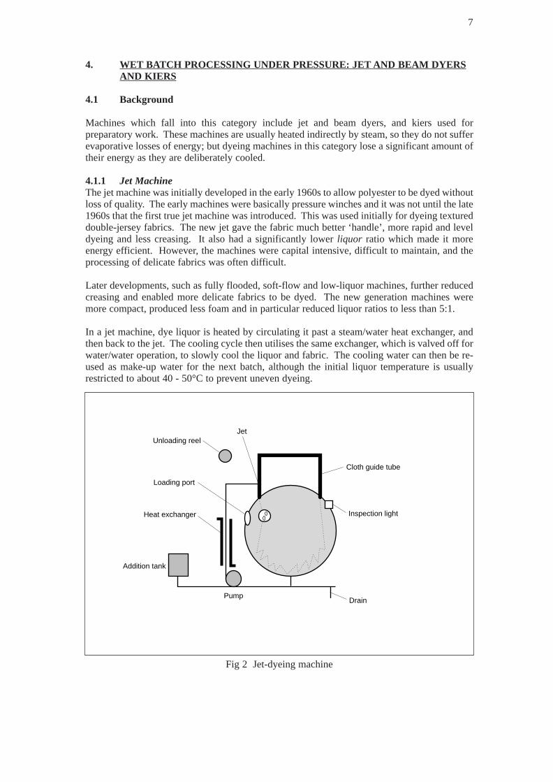
Machines which fall into this category include jet and beam dyers, and kiers used forpreparatory work. These machines are usually heated indirectly by steam, so they do not sufferevaporative losses of energy; but dyeing machines in this category lose a significant amount oftheir energy as they are deliberately cooled.
4.1.1 Jet MachineThe jet machine was initially developed in the early 1960s to allow polyester to be dyed withoutloss of quality. The early machines were basically pressure winches and it was not until the late1960s that the first true jet machine was introduced. This was used initially for dyeing textureddouble-jersey fabrics. The new jet gave the fabric much better ‘handle’, more rapid and leveldyeing and less creasing. It also had a significantly lower liquor ratio which made it moreenergy efficient. However, the machines were capital intensive, difficult to maintain, and theprocessing of delicate fabrics was often difficult.
Later developments, such as fully flooded, soft-flow and low-liquor machines, further reducedcreasing and enabled more delicate fabrics to be dyed. The new generation machines weremore compact, produced less foam and in particular reduced liquor ratios to less than 5:1.
In a jet machine, dye liquor is heated by circulating it past a steam/water heat exchanger, andthen back to the jet. The cooling cycle then utilises the same exchanger, which is valved off forwater/water operation, to slowly cool the liquor and fabric. The cooling water can then be re-used as make-up water for the next batch, although the initial liquor temperature is usuallyrestricted to about 40 - 50°C to prevent uneven dyeing.
7
Loading port
JetUnloading reel
Heat exchanger
Addition tank
PumpDrain
Inspection light
Cloth guide tube
Fig 2 Jet-dyeing machine
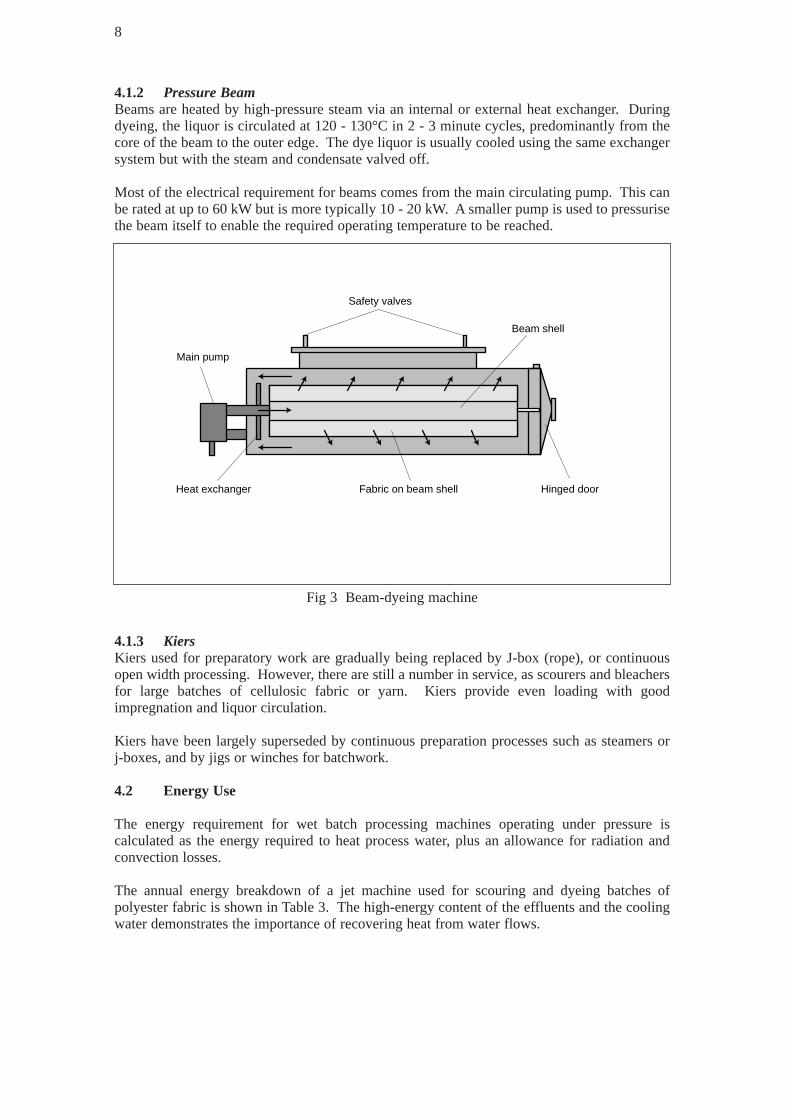
4.1.2 Pressure BeamBeams are heated by high-pressure steam via an internal or external heat exchanger. Duringdyeing, the liquor is circulated at 120 - 130°C in 2 - 3 minute cycles, predominantly from thecore of the beam to the outer edge. The dye liquor is usually cooled using the same exchangersystem but with the steam and condensate valved off.
Most of the electrical requirement for beams comes from the main circulating pump. This canbe rated at up to 60 kW but is more typically 10 - 20 kW. A smaller pump is used to pressurisethe beam itself to enable the required operating temperature to be reached.
4.1.3 KiersKiers used for preparatory work are gradually being replaced by J-box (rope), or continuousopen width processing. However, there are still a number in service, as scourers and bleachersfor large batches of cellulosic fabric or yarn. Kiers provide even loading with goodimpregnation and liquor circulation.
Kiers have been largely superseded by continuous preparation processes such as steamers or j-boxes, and by jigs or winches for batchwork.
4.2 Energy Use
The energy requirement for wet batch processing machines operating under pressure iscalculated as the energy required to heat process water, plus an allowance for radiation andconvection losses.
The annual energy breakdown of a jet machine used for scouring and dyeing batches ofpolyester fabric is shown in Table 3. The high-energy content of the effluents and the coolingwater demonstrates the importance of recovering heat from water flows.
8
Safety valves
Fabric on beam shell Hinged door
Beam shell
Main pump
Heat exchanger
Fig 3 Beam-dyeing machine

Table 3 Annual energy breakdown for a jet-dyeing machine
The energy and water requirements for common processes serviced by jets, beams and kiers aresummarised in Table 4.
Table 4 Typical energy and water requirements for pressure-dyeing machines
1 not including cooling water2 fabric passed through rope washer after scour3 although these processes are similar, there is a wide variation in both energy and water
requirement; this may be due to the use of different classes of dyestuffs to satisfy customerspecifications
4.3 Energy Efficiency Opportunities
There are many opportunities for saving energy and water on wet batch pressure-dyeingmachines. The systematic approach is to consider each of the following in turn.
• Reduce the Liquor RatioThe reduction of liquor ratio is potentially the most valuable opportunity for energy saving.Early jet machines typically had a ratio of 15:1. Modern machines have a reduced ratio of5:1 or less, with a 70% saving in water heating, although care must be taken to ensure thatthe solubility and dispersion stability characteristics of the dyestuff being used arecompatible with low liquor levels.
It may be possible to introduce another process altogether, such as foam application (with aliquor ratio of just 1:1) or pad dyeing at 2:1.
9
Component Energy content % of total Water discharge(GJ/year) temp (°C)
Scour effluent 278 18 40
Dye effluent 448 29 60
Cooling water 653 43 61
Radiation/convection losses 145 10
Total 1524 100
Process Specific energy consumption Specific water use (SWU)(SEC) (GJ/te) (m3/te)
Jet scour/dye 4.53 57.01
(polyester)
Beam scour/dye 11.53 82.01
(nylon)
Kier scour/wash 4.3 30.02
(cotton)
Kier bleach/wash 2.7 30.02
(cotton)

• Reduce the Process TemperatureA reduction in the process temperature may also be achieved by introducing alternativeprocesses. For example, under suitable circumstances, direct dyeing operated at 100 -120°C, may be replaced with reactive dyeing at 40 - 60°C, thus minimising water heating,fabric losses and radiation/convection losses.
• Reduce the Process TimeProcessing times can sometimes be reduced simply by making modifications to thetemperature profiles for certain dyeing cycles. This has been achieved at a number of sites,saving energy and improving productivity. Preparatory processes can also be speeded upjust by the use of different chemical formulations. One example, which involved modifyinga kier scour/bleach formulation, reduced processing times from ten hours to just over twohours.
• Combine Preparatory TreatmentsCombining preparatory treatments such as the de-sizing, scouring and bleaching of a cottonfabric could lead to a reduction from the original eight-stage process to just two stages, usinga steam purge and cold pad/batch technique. This eliminates three intermediate washings,one hot kier and a cold acid process, reducing the energy requirement by as much as 80%.
• Reduce the Need for Re-processingOne of the main causes of re-processing is the difficulty and time-consuming nature offabric sampling procedures, especially on older machines. It is therefore vital thatdyehouses aim to achieve correct shades quickly and consistently. This may be done simplyby improving manual control through better staff training. For large installations there arecomplete dyehouse management and control systems. These are capable of: – real time machinery supervision;– dye cycle editing;– production scheduling.
Dyehouse control systems are gradually shifting away from the more rigid read onlymemory (ROM) programmes, to flexible software programming which enables schedulesand processes to be tailored on-site. Product quality and productivity can be improvedwhilst the use of dyes, chemicals, water and energy are optimised.
Some dyehouses have introduced a policy of blind dyeing, accepting that a small percentageof the product will always need to be re-dyed. The success of this method depends partlyon the fibre/substrate involved; cotton might need considerable adjustment even on repeatshades, whilst consistent shading can generally be achieved on man-made fibres such aspolyester and nylon. Improved control will typically lead to just 5% of the product requiringshading, with a resultant energy saving of around 10 - 12%.
• Fit Insulation to MachinesInsulation can save up to 9% of the total energy requirement on wet batch processingmachines, with payback times typically less than 18 months. The nature of the processmeans that insulation material may be exposed to water, chemicals and physical shock. Anyinsulation should therefore be covered or coated with a hard-wearing, chemical/water-resistant outer layer.
• Re-use Liquors The recovery and re-use of liquor is becoming more important as the costs of effluentdischarge and treatment continue to increase. In addition, the re-use of hot (or warm) liquorscan significantly reduce energy requirements. For example, the warm rinse water in a kiercan be used to make up the next scour liquor, producing energy savings of more than 10%.
10
Similarly, spent dye liquor has been re-used at a hosiery dyeing company, where the numberof dye shades was limited, and there was opportunity to route the contaminated liquor froma given shade to the next batch of the same shade. In most dyehouses, where the work isdone on a commission basis, this approach would have limited application.
• Avoid Overflow Rinsing Overflow rinsing should be avoided wherever possible because it tends to use excessiveamounts of water. However, overflow rinsing is the only option for processes such aspolyester dyeing, where oligomer deposition may occur.
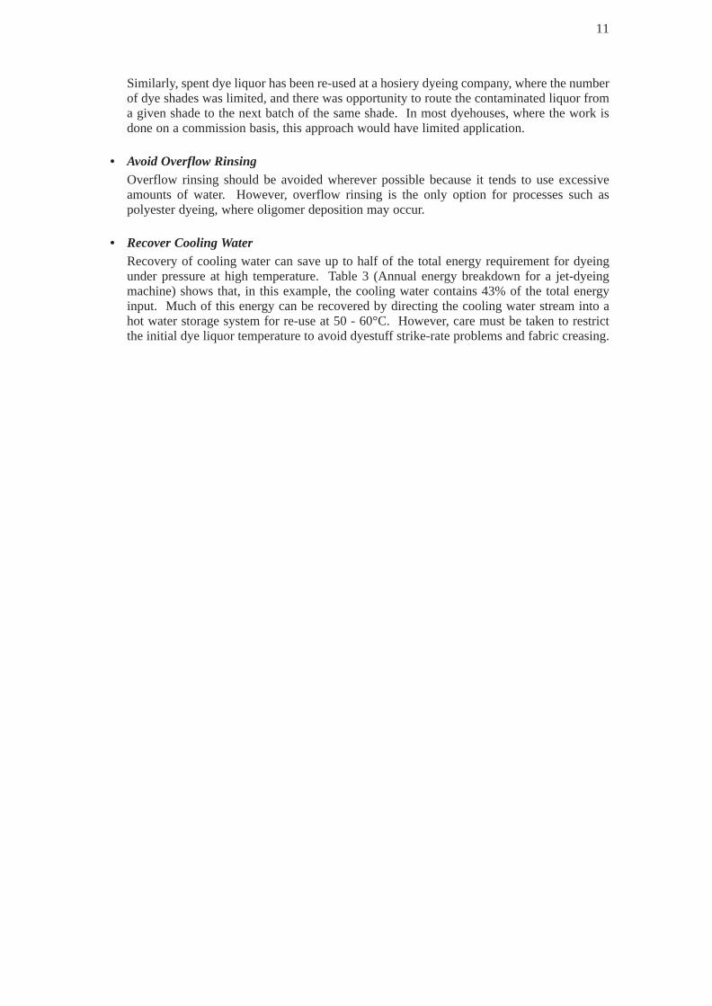
• Recover Cooling WaterRecovery of cooling water can save up to half of the total energy requirement for dyeingunder pressure at high temperature. Table 3 (Annual energy breakdown for a jet-dyeingmachine) shows that, in this example, the cooling water contains 43% of the total energyinput. Much of this energy can be recovered by directing the cooling water stream into ahot water storage system for re-use at 50 - 60°C. However, care must be taken to restrictthe initial dye liquor temperature to avoid dyestuff strike-rate problems and fabric creasing.
11

5. ATMOSPHERIC WET BATCH PROCESSING: JIG AND WINCHMACHINES
5.1 Background
Atmospheric wet batch processing differs from that carried out under pressure because itgenerally involves machines in which the evaporative losses are a significant proportion ofenergy consumption. The main machines in this category are the jig and the winch.
5.1.1 Jig MachineThis jig is one of the oldest machines used for dyeing woven fabric. The fabric is passed fromone roll to another, and back again, through a trough containing dye liquor. The liquor capacityis typically about 500 - 750 litres. Liquor is heated by direct injection of low-pressure steam,or indirectly, using higher-pressure steam through closed coils. Some jigs have both systemsfitted, using steam injection for rapid heating and the closed coils for maintaining the dyeingtemperature. Modern machines are usually fitted with a hood to help maintain temperature andminimise losses, although this is not always used, since operators find it inconvenient and theremay be fears of fabric spotting.
5.1.2 Winch MachineThe winch machine differs from the jig because it processes fabric in rope form rather thanopen width. This method imposes less tension on the fabric, but applies greater mechanicalaction. The winch is a very versatile machine and can be used for any type of fabric that canwithstand creasing, particularly knitted fabrics.
The liquor is usually heated by direct steam injection through a perforated pipe near the saltingbox. This provides both rapid heating and vigorous agitation at the box, which is used for dyeand chemical addition. However, as with all direct steam injection, there is a dilution effect totake into account. As with jigs, most winches are fitted with hoods to help maintaintemperature and minimise losses, but it is still a common sight to see hoods open whenprocessing at high temperatures.
12
Draw rollers
Hood
Perforatedsteam pipe
Closed coil
Fig 4 Jig machine

5.2 Energy Use
The energy used by atmospheric wet batch processing machines is calculated as the energyrequired to heat process water, plus an allowance for radiation, convection and evaporativelosses.
The annual energy breakdown for a winch dyehouse, processing a mixture of cotton and man-made fabrics, is shown in Table 5. The high-energy value of the evaporative lossesdemonstrates the importance of minimising evaporation from atmospheric dyeing vessels.Inthis example, the machine hoods were present, but were not used.
Table 5 Typical energy breakdown in a winch dyehouse
Table 6 relates energy and water usage to the quantity of fabric processed. This gives theaverage consumption per tonne (or specific consumption) for some of the most common jig andwinch processes.
13
Door
Jockey roller
Baffle plate
Drain plug
Steam pipe
Reel
Fig 5 Deep draught winch
Component Energy content % Water discharge temp(GJ/year) (°C)
Dye effluent 9,861 57 79
Evaporative losses 7,303 43 -
Total 17,164 100 -

Table 6 Typical energy usage for atmospheric dyeing machines
5.3 Energy Efficiency Opportunities
• Installation and Use of Covers or HoodsUsing covers or hoods may seem obvious, but many jigs and winches are operated at hightemperatures with hoods open. Using covers or hoods can reduce evaporative losses byapproximately half. Evaporation is particularly important above 60°C.
• Careful Control of TemperatureOverheating, and in particular overboiling, is a common problem. It is most often causedby poor control and especially affects older machines. The maximum achievabletemperature in an atmospheric vessel is 95 - 100°C. Once the dye liquor is boiling, furtherheat input will not raise the temperature, but will increase evaporation. Although a fasterboil does lead to greater agitation of the fabric, this can be achieved more efficiently byfitting a circulator. At temperatures above 80°C, live steam breakthrough may occur; asmuch as 15% of steam can be lost in this way. Table 7 illustrates the energy savings thatcan be achieved by reducing temperature and by consistently closing the hoods on jigmachines.
Table 7 Steam used by a jig machine with varying temperature and conditions
14
Process Specific energy consumption Specific water requirement(GJ/te) (m3/te)
Jig scouring/dyeing 6.7 12.0(heavyweight cotton)
Jig dyeing 5.6 21.0(mediumweight cotton)
Winch bleaching 16.0 48.0(wool)
Winch dyeing 12.5 22.0(acrylic)
Operating temperature Steam use(°C) (kg/hour)
Hood open Hood closed
80 50 23
90 61 28
95 73 34
100 (simmer) 91 55
100 (vigorous boil) 218 127

The energy savings, even for small reductions in operating temperature, are significant; a jigmachine set at 95°C uses only about 33% of that needed for a vigorous boil (both with hoodsopen). Closing the hoods makes even more difference. Just changing from a vigorous boilto a simmer (keeping operating temperature at 100°C) and closing hoods reduces energy useby 75%. The use of computer based control systems can not only provide an opportunity forcloser control, but also the ability to log the operating conditions.
• Introduction of Effluent Heat RecoveryEffluent heat recovery in a dyehouse may be difficult since the effluent consists of both hot(exhausted dye liquor) and cold (rinse water) streams. Where pressure vessels are used thereis the possibility of re-using the cooling water, which may drop the hot effluent temperaturedown to about 60°C. The effluent from atmospheric vessels could be significantly hotterthan this. Table 5 showed an average dye effluent temperature of 79°C, which is notunusual. If the temperature of the combined effluent streams from a dyehouse falls to below40°C after the introduction of the cold rinse water, conventional heat recovery cannotnormally be justified.
However, it may be worth considering segregation of hot and cold streams, eitherautomatically or manually. This would be followed by balancing heat recovery and make-up water storage.
15

6. CONTINUOUS WET PROCESSING
6.1 Background
Continuous wet processing generally applies to washing-off after preparatory processes such asscouring, bleaching and mercerising, or washing-off after dyeing. A continuous washing rangeis made up of a number of tanks, compartments or becks connected by tension compensatorsand nip rollers. The fabric is threaded, open width, around a series of rollers in each tank. Therollers help to increase liquor agitation and the transfer of impurities, to improve washingefficiency.
The energy usage of a continuous wet process is calculated as the heat required to raise watertemperature, plus allowances for nip losses, radiation, convection and evaporative losses.
The annual energy breakdown of a seven-tank washing range, used to wash off mediumweightcotton fabric after bleaching, is shown in Table 8. In this example, six of the tanks are operatedat 80ºC and four are counterflow. Water is used at a rate of 20 m3/te (cubic metres of water pertonne of fabric), and is heated directly, using live steam. A large proportion of the losses occurat the nips between each tank.
Table 8 Typical energy breakdown for a washing range
16
Fabric flow
Nips
Counterflow washing
SteamerImpregnate
Drying range
Fig 6 Continuous washing range
Component Energy content %(kW)
Water heating 563 50
Nip losses 401 36
Radiation and convection losses 22 3
Evaporation losses 128 11
Total 1,114 100
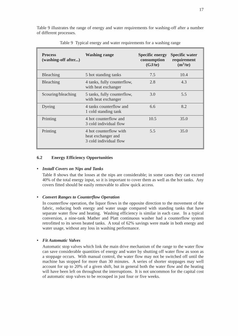
Table 9 illustrates the range of energy and water requirements for washing-off after a numberof different processes.
Table 9 Typical energy and water requirements for a washing range
6.2 Energy Efficiency Opportunities
• Install Covers on Nips and TanksTable 8 shows that the losses at the nips are considerable; in some cases they can exceed40% of the total energy input, so it is important to cover them as well as the hot tanks. Anycovers fitted should be easily removable to allow quick access.
• Convert Ranges to Counterflow OperationIn counterflow operation, the liquor flows in the opposite direction to the movement of thefabric, reducing both energy and water usage compared with standing tanks that haveseparate water flow and heating. Washing efficiency is similar in each case. In a typicalconversion, a nine-tank Mather and Platt continuous washer had a counterflow systemretrofitted to its seven heated tanks. A total of 62% savings were made in both energy andwater usage, without any loss in washing performance.
• Fit Automatic ValvesAutomatic stop valves which link the main drive mechanism of the range to the water flowcan save considerable quantities of energy and water by shutting off water flow as soon asa stoppage occurs. With manual control, the water flow may not be switched off until themachine has stopped for more than 30 minutes. A series of shorter stoppages may wellaccount for up to 20% of a given shift, but in general both the water flow and the heatingwill have been left on throughout the interruptions. It is not uncommon for the capital costof automatic stop valves to be recouped in just four or five weeks.
17
Process Washing range Specific energy Specific water(washing-off after...) consumption requirement
(GJ/te) (m3/te)
Bleaching 5 hot standing tanks 7.5 10.4
Bleaching 4 tanks, fully counterflow, 2.8 4.3with heat exchanger
Scouring/bleaching 5 tanks, fully counterflow, 3.0 5.5 with heat exchanger
Dyeing 4 tanks counterflow and 6.6 8.2 1 cold standing tank
Printing 4 hot counterflow and 10.5 35.03 cold individual flow
Printing 4 hot counterflow with 5.5 35.0heat exchanger and3 cold individual flow

• Introduce Heat Recovery EquipmentInstalling heat recovery equipment on a continuous washer is usually a simple but veryeffective measure, since water inflow and effluent outflow are matched, eliminating the needfor holding tanks. The effluent from these machines can become contaminated with fibrousmaterial, so it is important to install a heat exchanger capable of handling such loads. Oneoption is a self-cleaning, rotating element exchanger which has an efficiency of about 70%.Another is to fit a simple plate heat exchanger with a pre-filter, which may have a higherinitial cost, but is capable of efficiencies in excess of 90%. (See GPCSs 28, 30 and 31-Heatrecovery from contaminated effluent.)
Table 9 illustrates the energy saving potential of a heat exchanger on a continuous washer.In this example, the range was used for washing-off after printing. Without heat recovery,the machine operated at a SEC of 10.5 GJ/te fabric processed, and an SWR of 35.0 m3/te.A rotating element heat exchanger was fitted to the hot counterflow section of the range andthe average SEC dropped to just 5.5 GJ/te.
• Improve Flow CharacteristicsImprovement of the flow characteristics and the washing efficiency of washing ranges needsto be addressed by manufacturers. Ideally, the range should comprise smaller tanks, eachcontaining less water than at present and with an improved shape to eliminate relativelystagnant regions. In addition, washing action and water removal could be improved byemploying suction between the tanks in place of nip rollers. However, the running costs ofthis option are about three times higher than those for nips per kg water removed. Researchwork done by the British Textile Technology Group and others has led to the specificationof an ‘ideal’ energy and water efficient washer. These are the basic requirements:– counterflow operation;– wash water flow rate matched to washing requirements;– large number of stages or tanks (up to 80);– washing parameters identical for each stage;– wash water to be brought into intimate contact with the textile (this is achieved by
throughflow which dictates either suction or pressure action).
18
Fig 7 Rotating plate heat exchanger
Cold water in
Centralrotating element
Heated water out
Hoteffluent in
Effluentto drain

• Improve Washing ActionExcept for washing-off after scouring where hot water is required to prevent precipitation ofthe soap products, washing on the ideal machine could be done cold, thereby saving aconsiderable amount of energy without reducing the washing efficiency.
• Reduce Live Steam PressureA reduction in live steam pressure can prevent steam breakthrough, thus improving heattransfer efficiency in direct steam heating applications. Similarly, reducing steam pressurein closed coils carries the advantage that lower pressure steam has a higher latent heatcontent.
• Fit Thermostats/Temperature IndicatorsManual control of steam valves must be carefully managed to ensure that tanks are run atoptimum temperatures; the fitting of temperature indicators and thermostatic valves can leadto significant energy savings.
• Introduce Point-of-Use Water HeatingPoint-of-use gas-fired water heaters can be used to enable processes to be run independentlyof site central boiler systems. This means that the boiler and distribution losses associatedwith centralised systems (which can be as much as 50% of the gross fuel input) can beeliminated. Point-of-use heating also offers greater flexibility since it allows operation ofprocesses outside main boiler operating hours.
Many of the measures highlighted above can be introduced on existing machines atrelatively low cost and the energy and water savings that they achieve mean that the newequipment will pay for itself quickly.
19
7. CONTACT DRYING USING STEAM CYLINDERS
7.1 Background
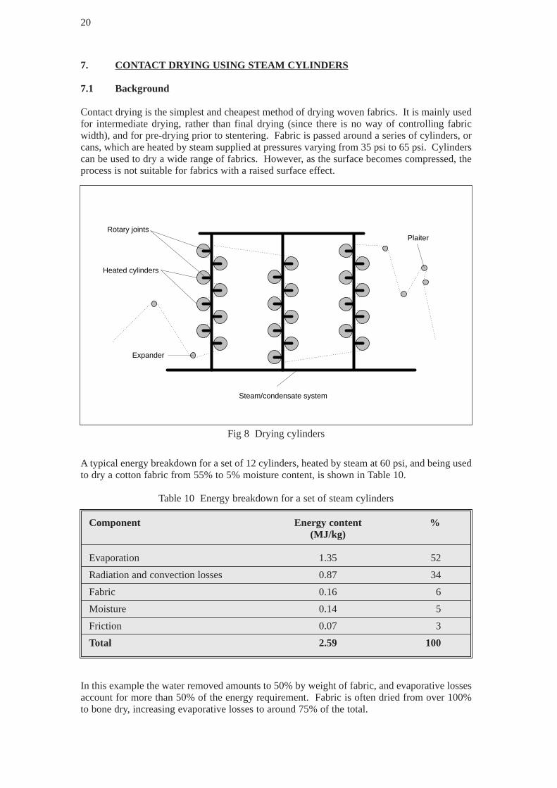
Contact drying is the simplest and cheapest method of drying woven fabrics. It is mainly usedfor intermediate drying, rather than final drying (since there is no way of controlling fabricwidth), and for pre-drying prior to stentering. Fabric is passed around a series of cylinders, orcans, which are heated by steam supplied at pressures varying from 35 psi to 65 psi. Cylinderscan be used to dry a wide range of fabrics. However, as the surface becomes compressed, theprocess is not suitable for fabrics with a raised surface effect.
A typical energy breakdown for a set of 12 cylinders, heated by steam at 60 psi, and being usedto dry a cotton fabric from 55% to 5% moisture content, is shown in Table 10.
Table 10 Energy breakdown for a set of steam cylinders
In this example the water removed amounts to 50% by weight of fabric, and evaporative lossesaccount for more than 50% of the energy requirement. Fabric is often dried from over 100%to bone dry, increasing evaporative losses to around 75% of the total.
20
Component Energy content %(MJ/kg)
Evaporation 1.35 52
Radiation and convection losses 0.87 34
Fabric 0.16 6
Moisture 0.14 5
Friction 0.07 3
Total 2.59 100
Rotary joints
Heated cylinders
Expander
Steam/condensate system
Plaiter
Fig 8 Drying cylinders

7.2 Energy Efficiency Opportunities
Opportunities for making energy savings on drying cylinders may involve the introduction ofreplacement or additional equipment, or simply a change of working practices to improve theenergy efficiency of existing plant:
• Introduce Mechanical Pre-dryingMechanical pre-drying methods such as mangling, centrifugal drying, suction slot or airknife de-watering are used to reduce drying costs by removing some of the water from thefabric prior to contact drying. In order to select the best method, the limit retentioncapabilities of each system are balanced against their running costs. For instance, a slot isthree times more energy intensive than a typical mangle, but consistently provides lowerwater retention rates over a range of fabric types.
The effectiveness of mangling depends on a number of factors: the diameter and hardnessof the bowl; the pressure applied; the temperature of the water in the fabric; and the fabricspeed.
Suction slots can quite easily be located in front of a stenter or set of cans. The slots drawair through the fabric which runs at speed over a slot configuration. The extracted air/wateris then filtered and passed through a water separator. Although they are very effective, slotsrequire a high electrical power input (up to about 50 kW). Narrower fabrics areaccommodated by covering the lengths of slot at either side of the fabric with a rubberisedblind. As well as de-watering, the slot can be used to recover excess chemicals padded ontothe fabric. These additional savings can be used to offset the running costs of the system.
21
FabricVacuumgauge
Wash waterFilter
Waterseparator
Drain
Air operateddiaphragm pump
To drain orreturn toimpregnation bath
Inlet silencer Exhauster
Outletsilencer
Water
Non-returnvalve
Vacuum controland relief
Suction slot(sealing flaps not shown)
P
P
Fig 9 Suction slot
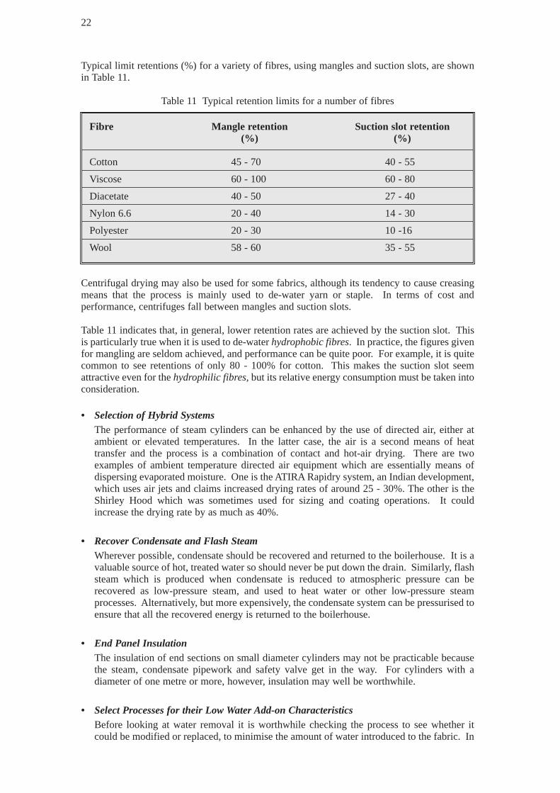
Typical limit retentions (%) for a variety of fibres, using mangles and suction slots, are shownin Table 11.
Table 11 Typical retention limits for a number of fibres
Centrifugal drying may also be used for some fabrics, although its tendency to cause creasingmeans that the process is mainly used to de-water yarn or staple. In terms of cost andperformance, centrifuges fall between mangles and suction slots.
Table 11 indicates that, in general, lower retention rates are achieved by the suction slot. Thisis particularly true when it is used to de-waterhydrophobic fibres. In practice, the figures givenfor mangling are seldom achieved, and performance can be quite poor. For example, it is quitecommon to see retentions of only 80 - 100% for cotton. This makes the suction slot seemattractive even for the hydrophilic fibres, but its relative energy consumption must be taken intoconsideration.
• Selection of Hybrid SystemsThe performance of steam cylinders can be enhanced by the use of directed air, either atambient or elevated temperatures. In the latter case, the air is a second means of heattransfer and the process is a combination of contact and hot-air drying. There are twoexamples of ambient temperature directed air equipment which are essentially means ofdispersing evaporated moisture. One is the ATIRA Rapidry system, an Indian development,which uses air jets and claims increased drying rates of around 25 - 30%. The other is theShirley Hood which was sometimes used for sizing and coating operations. It couldincrease the drying rate by as much as 40%.
• Recover Condensate and Flash SteamWherever possible, condensate should be recovered and returned to the boilerhouse. It is avaluable source of hot, treated water so should never be put down the drain. Similarly, flashsteam which is produced when condensate is reduced to atmospheric pressure can berecovered as low-pressure steam, and used to heat water or other low-pressure steamprocesses. Alternatively, but more expensively, the condensate system can be pressurised toensure that all the recovered energy is returned to the boilerhouse.
• End Panel InsulationThe insulation of end sections on small diameter cylinders may not be practicable becausethe steam, condensate pipework and safety valve get in the way. For cylinders with adiameter of one metre or more, however, insulation may well be worthwhile.
• Select Processes for their Low Water Add-on CharacteristicsBefore looking at water removal it is worthwhile checking the process to see whether itcould be modified or replaced, to minimise the amount of water introduced to the fabric. In
22
Fibre Mangle retention Suction slot retention(%) (%)
Cotton 45 - 70 40 - 55
Viscose 60 - 100 60 - 80
Diacetate 40 - 50 27 - 40
Nylon 6.6 20 - 40 14 - 30
Polyester 20 - 30 10 -16
Wool 58 - 60 35 - 55

particular, the application of finishes using foam, lick roller or spray application methodscould be considered.
• Avoid Intermediate DryingConsiderable savings in energy can be made by avoiding intermediate drying betweenprocesses. For example, there are systems which allow finishes to be applied ‘wet on wet’to reduce drying requirements (although this is less beneficial for dyeing).
Typically a fabric is dried two, three or even four times during its passage through afinishing works. As well as being energy intensive, drying tends to be the bottleneckoperation. If just one of the drying stages could be eliminated there would be a substantialimprovement in both energy efficiency and production capacity.
• Avoid OverdryingOverdrying of fabric is a very common problem. Fibres have an equilibrium regain, ornatural moisture level, below which it is pointless to dry. For some fibres the regain valuecan be quite high. It is therefore important to control the speed of the drying cylinders sothat the equilibrium moisture level is not exceeded. Typical regains at 20°C and 65%relative humidity (RH) are shown in Table 12.
Table 12 Typical regain values for a number of fibres
On sites where it is common practice to dry fabrics to ‘bone dry’ condition, the potential formaking savings is considerable. Hand-held moisture meters can be used with a roller sensorto monitor the moisture content of fabric leaving the drying cylinders to ensure thatoptimum drying is taking place.
• Reduce Idling Times and Using Multiple Fabric DryingCareful scheduling of fabric batches arriving at the cylinders can reduce idling time,therefore saving energy. Similarly, efficiency can be improved by making cylinders extrawide to allow two batches of narrow fabric to run side by side.
• Operating Cylinders at Higher Steam PressuresCylinders can be operated at higher steam pressures and temperatures to reduce radiationand convection losses compared to evaporative energy.
23
Fibre Regain value (%)
Cotton 7.0
Wool 16 - 18
Viscose 12.5
Diacetate 6.9
Triacetate 4.5
Nylon 6.6 4.3
Nylon 6 4.4
Polyester 0.4
Acrylic 1.5
Polypropylene 0.0

• MaintenanceCommon leak sites for steam cylinders are the vacuum breakers, air vents, rotating jointsand steam traps. A single bank often comprises 32 cylinders, so the potential for leakage isconsiderable. It is therefore important to have a good maintenance regime which shouldinclude periodic checking of steam traps using an ultrasonic steam-leak detector.
24
8. HOT-AIR DRYING USING STENTERS
8.1 Background
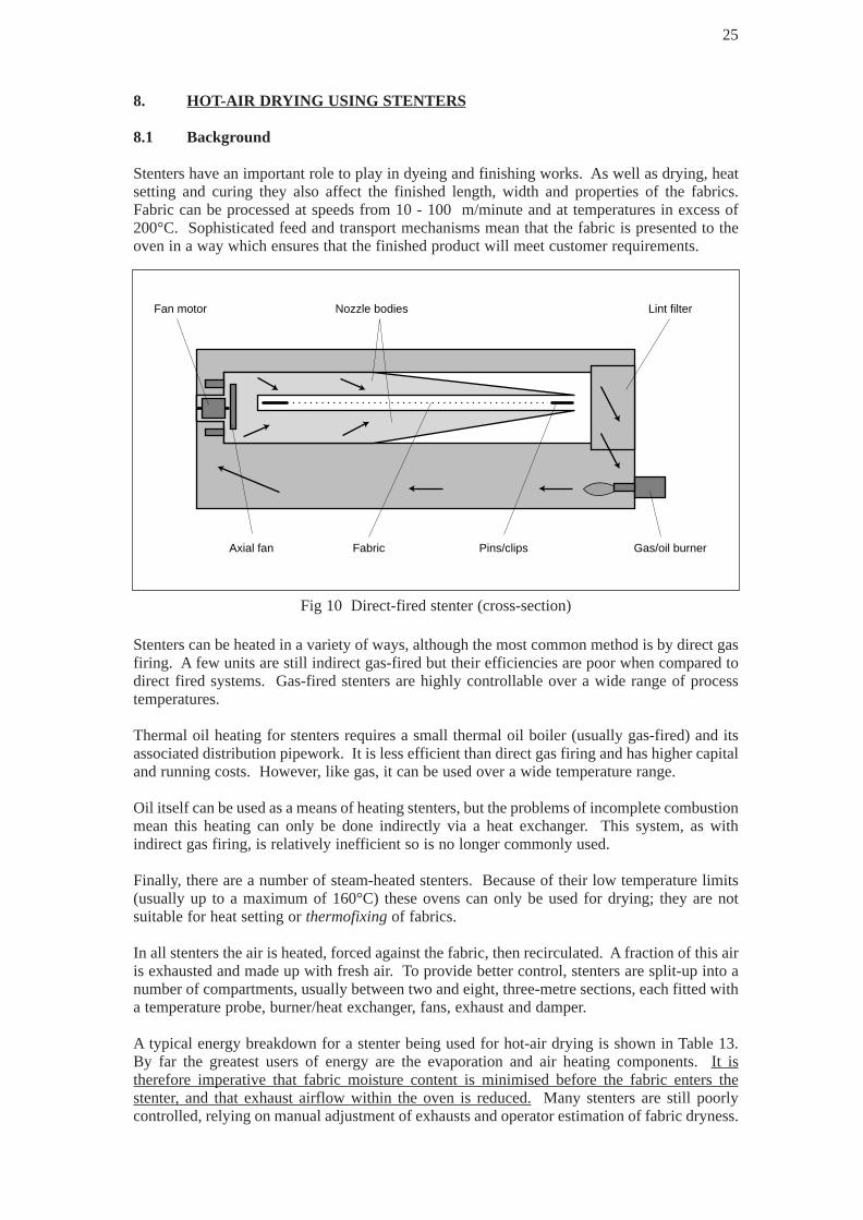
Stenters have an important role to play in dyeing and finishing works. As well as drying, heatsetting and curing they also affect the finished length, width and properties of the fabrics.Fabric can be processed at speeds from 10 - 100 m/minute and at temperatures in excess of200°C. Sophisticated feed and transport mechanisms mean that the fabric is presented to theoven in a way which ensures that the finished product will meet customer requirements.
Stenters can be heated in a variety of ways, although the most common method is by direct gasfiring. A few units are still indirect gas-fired but their efficiencies are poor when compared todirect fired systems. Gas-fired stenters are highly controllable over a wide range of processtemperatures.
Thermal oil heating for stenters requires a small thermal oil boiler (usually gas-fired) and itsassociated distribution pipework. It is less efficient than direct gas firing and has higher capitaland running costs. However, like gas, it can be used over a wide temperature range.
Oil itself can be used as a means of heating stenters, but the problems of incomplete combustionmean this heating can only be done indirectly via a heat exchanger. This system, as withindirect gas firing, is relatively inefficient so is no longer commonly used.
Finally, there are a number of steam-heated stenters. Because of their low temperature limits(usually up to a maximum of 160°C) these ovens can only be used for drying; they are notsuitable for heat setting or thermofixingof fabrics.
In all stenters the air is heated, forced against the fabric, then recirculated. A fraction of this airis exhausted and made up with fresh air. To provide better control, stenters are split-up into anumber of compartments, usually between two and eight, three-metre sections, each fitted witha temperature probe, burner/heat exchanger, fans, exhaust and damper.
A typical energy breakdown for a stenter being used for hot-air drying is shown in Table 13.By far the greatest users of energy are the evaporation and air heating components. It istherefore imperative that fabric moisture content is minimised before the fabric enters thestenter, and that exhaust airflow within the oven is reduced.Many stenters are still poorlycontrolled, relying on manual adjustment of exhausts and operator estimation of fabric dryness.
25
Fan motor Nozzle bodies Lint filter
Gas/oil burnerPins/clipsFabricAxial fan
Fig 10 Direct-fired stenter (cross-section)

Table 13 Energy breakdown for a typical stenter
8.2 Energy Efficiency Opportunities
• Introduce Mechanical De-watering or Contact Drying Before StenteringStentering is an energy intensive process, so it is important to remove as much water aspossible before the fabric enters the oven. This can be achieved using mechanical de-watering equipment such as mangles, centrifuges, suction slots and air knives; or by contactdrying using heated cylinders. Contact drying is roughly five times more energy intensivethan suction slot de-watering, but nevertheless uses only half to two-thirds the energy of astenter. Pre-drying fabric to about 25 - 30% regain before passing it through the stenter stillallows fabric width to be adjusted to suit customer requirements.
Other techniques used to reduce drying costs include infra-red and radio frequency drying.Gas-fired infra-red has been used for the pre-drying of textiles prior to stentering. This canhave the effect of increasing drying speeds by up to 50%, thereby relieving productionbottlenecks which tend to occur at stenters. In addition, energy savings in the region of 50 - 70% can be achieved, compared to conventional stenter drying. If an efficient meansof pulling the fabric out to width could be devised for a short hot-zone length, then infra-redcould be used to do all the drying.
Radio frequency drying is used extensively for the drying and dye fixing of loose stock,packages, tops and hanks of wool and sewing cotton. The energy requirement of radiofrequency drying is approximately 70% that of a conventional steam-heated dryer.However, its use is limited to loose stock and packages. It cannot be modified, as yet, toaccommodate knitted or woven fabric since the traditional pins and clips of the stentertransport mechanism interfere with the radio frequency drying field, causing discharge.
26
Component Energy content %(GJ/te)
Evaporation 2.54 41.0
Air heating 2.46 39.7
Fabric 0.29 4.6
Case 0.39 6.3
Chain 0.09 1.5
Drives 0.43 6.9
Total 6.20 100.0
Zone 2Gas fired hot air
and radio frequency
Zone 1Gas fired hot air
~115°C ~90°C
Recirculationfan
Recirculationfan
Impregnatingbath
Extract system
Guillotine
Dried web
Nip rolls Let off
Conveyor belt
Fig 11 ARFA dryer

• Avoiding OverdryingThe high-energy cost of running a stenter means that it is vital to avoid overdrying.Automatic infra-red, radioactive (source) or conductivity-based moisture measurementsystems can be linked to the stenter speed control to ensure that the appropriate fabric regainvalue is achieved.
• Close Off Exhaust Streams During IdlingCommission dyers and finishers often operate with relatively small batch sizes. In extremecases this may mean that the fabric feed to machines is being changed every hour. It iscommon practice to leave the exhaust systems running during these changeovers, whichmay take 10 - 15 minutes or more. Since stenters have a large air-heating requirement it isimportant, whenever possible, to isolate the exhausts, or at least partially close them down,during idle periods.
• Drying at Higher TemperaturesDrying at a higher temperature, if the fabric will tolerate it, means that radiation andconvection losses become relatively small compared to evaporation energy.
• Close and Seal Side PanelsOn older machines the side panels may become damaged, upsetting the air balance withinthe oven sections. All faulty panels should be repaired or replaced to provide an effectiveseal around the oven.
• InsulationImproving stenter insulation is not usually practicable, although on some older machines itmay be cost-effective to insulate the roof panels.
• Optimise Exhaust HumidityTable 13 showed that the main energy requirements for a stenter are for air heating andevaporation. In order to optimise drying rate and energy use, air flow through the oven (andtherefore exhaust rate) must be carefully controlled. A significant number of stenters stillrely on manual control of exhausts, although this is actually very difficult and often meansthat exhausts are left fully open unnecessarily.
For optimum performance, exhaust humidity should be maintained between 0.1 and 0.15 kgwater/kg dry air. It is not unusual to find stenters with an exhaust humidity of only 0.05 kgwater/kg dry air, indicating that the exhaust volume is too high and excessive energy is beingused to heat air. Equipment is available which will automatically control dampers tomaintain exhaust humidity within the specified range, thereby cutting air losses withoutsignificantly affecting fabric throughput. Controllers vary from wet/dry bulb temperaturesystems to fluidic oscillators measuring the variation in sound through a special filter head.
Drying of solvent-based work requires much greater exhaust volumes for safety reasons,leading to higher air losses. However, many solvent-based systems have now been replacedby aqueous systems to satisfy the requirements of the Environmental Protection Act (EPA).
• Install Heat Recovery EquipmentExhaust heat recovery can be achieved by using air-to-air systems such as plate heatexchangers, glass tube heat exchangers or heat wheels. Efficiencies are generally about 50 - 60%, but there can be problems with air bypass, fouling and corrosion. If othermeasures, such as fabric moisture control and exhaust humidity control, are installed, heatrecovery may not be cost-effective.
27

Air-to-water systems, such as spray recuperation, avoid fouling and clean the exhaust, butmay give rise to corrosion. Secondary water/water heat exchange equipment is required anda matching heat requirement must be identified.
If large quantities of volatile organics or formaldehyde are generated by the stenter, someform of scrubber, electrostatic precipitator or even an incinerator may be required to complywith the statutory limits of the EPA. In these cases, it may be sensible to incorporate heatrecovery so that at least part of the installation costs can be recovered.
• Converting to Direct Gas FiringCompared with other stenter heating systems, direct gas firing is both clean and cheap.When it was first introduced there was concern that oxides of nitrogen, formed by exposureof air to combustion chamber temperatures, would cause fabric yellowing or partialbleaching of dyes. This has since been shown to be unjustified. Unlike steam and thermaloil systems there are no distribution losses. Heating up times are shorter and thermalcapacities are lower, all leading to reduced idling losses.
28

9. HOT-AIR/STEAM HEA T TREATMENTS
9.1 Background
Hot-air and steam heat treatment processes include curing, heat setting, baking, dye fixing andsteaming. The main equipment used for heat setting, curing and fixing is the stenter. Hot fluesare used for baking and fixing and a variety of steamers for dye fixing and some preparatorywork.
Heat setting of fabric to improve stability is generally achieved at temperatures in excess of180°C. It is particularly important in the treatment of polymeric materials, which may be pre-set prior to preparation and dyeing if they are susceptible to creasing or shrinkage. To preventpermanent creases being formed in polyester fabric, for example, it must be pre-set beforescouring and disperse dyeing in rope form on a jet-dyeing machine.
Stenter curing of fabrics is used to complete polymerisation or the condensation reaction of anadded substance (usually padded on).
Fixing of dyestuffs can be achieved in a number of ways depending on the fabric, dyestuff andcustomer requirements.
Thermosol fixing is a means of colour-fixing mainly polyester/cotton fabrics by heat treatingat temperatures of 200 - 220°C for up to one minute. The process normally uses specificthermosol units set within a continuous dyeing range, but it can also be carried out in a stentercapable of operating at high temperatures.
Continuous steamersare used for the diffusion and fixing of vat, sulphur and direct cottondyes. The fabric is passed through a steamer set at 102 - 110°C, with fabric contact times of upto 60 seconds. The minimisation of air in the system reduces evaporation temperature, ensuringrapid heating of the fabric and improved diffusion/fixing of the dyestuff.
Steamerscan also be used to provide a means of rapid, continuous preparation. Fabric isimpregnated with caustic or hydrogen peroxide prior to treatment in the steam atmosphere.
Table 14 shows a typical energy breakdown for heat setting processes. These tend to bedominated by air losses, which account for about 80% of the total energy input. It is thereforeimportant to minimise air losses by controlling the exhaust.
Table 14 Energy breakdown for heat setting
29
Component Energy content %(GJ/te)
Evaporation 0.20 4.3
Air heating 3.55 76.2
Fabric 0.25 5.4
Case 0.23 4.9
Chain 0.10 2.1
Drives 0.33 7.1
Total 4.66 100.0

9.2 Energy Efficiency Opportunities
• Select Processes Which Require Less Energy/te Fabric ProcessedResearch work has shown that infra-red panels could be used to improve the energyefficiency of heat setting and dye fixing processes. At the same time:– stenter hot zones could be reduced to less than two metres, allowing much faster fabric
throughput; – 8% shrinkage could be achieved on nylon fabrics at speeds of 30 metres/minute with a
hot zone length of 0.25 metre;– dye fixing times could be halved, compared with conventional stenter treatments.
• Minimise Air LossAir exhaust is necessary to remove the small amounts of volatiles that are released from thefabric at high temperatures during heat setting and dye fixing processes. The air lossesassociated with this exhaust account for the bulk of the energy used in hot-air treatments. Intheory it should be quite safe to operate stenter ovens with exhaust rates of 10 kg air/kgfabric processed. In practice, finishers tend to employ about 15 kg air/kg fabric.Optimisation by reducing exhaust rates can therefore lead to energy savings of up to 30%.However, there are some fabrics and processes (notably pre-setting of some synthetics)which cause considerable fume problems, leading to a characteristic ‘blue haze’ emanatingfrom the fabric slots. In these cases the stenter may be required to operate with fully openexhausts.
• Control and MaintenanceA number of low or no-cost measures can be introduced to improve the energy efficiency ofhot-air/steam heat treatment equipment. For example, the side and top panels of thermosolunits, bakers and steamers can be insulated to minimise heat losses. Heat transfer rateswithin thermosol units tend to be not very good, so it is important that the fabric enteringthe unit is as dry as possible. There may be potential to re-use, or recover heat from, thewarm water flowing from the exit water seal of steamers.
30
10. FUEL, STEAM RAISING PLANT AND DISTRIBUTION SYSTEMS
10.1 Background
Textile dyeing and finishing plant generally uses gas or dual oil/gas-fired package boilers forsteam raising. Very few companies still operate coal-fired systems, since these are regarded asbeing dirty and relatively costly. Gas is seen to be a clean, convenient fuel of consistent quality.It does not require fuel storage tanks or heated distribution lines, and produces less corrosiveflue gas than either fuel oil or coal.
Most modern boilers used in textile processing plant are of a three-pass shell type, rated ataround 150 psi. The combustion chamber is completely enveloped in the boiler shell, enablingheat to be transferred very efficiently. Shell boilers do have some minor drawbacks comparedto the older Lancashire or ‘economic’ boilers in that they tend to have limited steam storagecapacity and will not tolerate hard water. However, these disadvantages are offset by fasterresponse times and higher efficiency. Site steam requirement is generally in the range 2,250 -13,600 kg/hr, stepped down from generated pressures to about 40 - 80 psi for most process uses.
Textile dyeing and finishing companies are usually small to medium-sized companiesemploying less than 500 people. Process energy requirements are normally met by:• steam from a centralised boiler plant for water heating, contact heating systems and space
heating (thermoliers); • direct gas firing for stenters, bakers, singeing, thermosol units, infra-red panels, coating
machines, localised water heating, thermal oil boilers and space heating (infra-red andconvection);
• electricity for lighting, overall motive power, compressed air systems and specifically onprocesses such as raising, glazing, schreinering and beaming.
10.2 Energy Efficiency Opportunities
• Minimise Flue Gas and Other Boiler LossesTo minimise flue gas losses from a boiler, it is essential to check that the fuel/air mixture atthe burner is correct. Too much air will cool the boiler unnecessarily and may even preventcomplete combustion of the fuel. Similarly, too little air will lead to incomplete combustionand fuel wastage. When the fuel/air mixture is right, the proportion of carbon dioxide in theflue gases is maximised and combustion efficiency is at its greatest. Automatic controlsystems are used to monitor flue gas composition (e.g. by measuring oxygen content) andprovide feedback to vary the fuel/air mixture to obtain optimum combustion efficiency.
As well as monitoring flue gas composition on a regular basis, the gas temperature shouldalso be checked. A rise of more than 15 - 20°C above ‘normal’ flue temperatures should beinvestigated as this may indicate: scaling of the boiler tubes on the water side; sooting up ofthe tubes on the fire side; or flame impingement on the back plate. Any one of theseoccurrences will reduce boiler efficiency.
Unburned fuel is another source of loss from a boiler. For gas and oil this should be zero,and should be checked by testing for carbon monoxide and black smoke respectively.However, for coal there is always a proportion of non-combustible ash and grit which mustbe taken into account. Analysis of the coal will provide a figure from which these losses canbe calculated.
Radiation losses from a well-insulated modern boiler at high fire will be as little as 2 - 3%.All boilers are most efficient at high fire. At half load, radiation losses increase to 6% andat a quarter output, to 12%. It is therefore important to size a boiler correctly and to run itat full fire if at all possible.
31
Blowdown, or regular venting of boiler water into a flash vessel, is used to reduce the totaldissolved solids (TDS) content of boiler water. For shell boilers, the maximum acceptableTDS level is 3,500 ppm. Although it is an essential process, venting boiler water in this waydoes mean that some energy is wasted. Where the blowdown rate is high, it may beworthwhile installing a heat exchanger in tandem with the flash vessel. The recovered heatcan be utilised in the feed water tank.
• Return Condensate to the BoilerMost steam heating in dyeing and finishing plant takes place as indirect, closed coil heating.Direct heating, using live steam, is generally only applied to atmospheric batch vessels andto some wash tanks. To minimise water treatment costs and energy losses it is thereforeimportant to return as much condensate as possible to the boiler. Once this has beenachieved, a system of regular steam trap checking and maintenance should be introduced toensure that the condensate is returned efficiently and that no steam is passed back. Smallhand-held ultrasonic steam trap indicators may be used to pinpoint traps that are seized upor are passing.
• LaggingInsulation of steam and condensate pipework is essential to prevent large distribution losses,but it is surprising how many sites still have partially insulated steam lines, uninsulatedvalves and flanges or wholly uninsulated condensate return systems. The capital cost ofsteam line insulation can usually be recovered in six months, or about ten months for lowertemperature condensate lines. It is, therefore, one of the most cost-effective ways to reduceenergy wastage. Resistance to lagging may be because, generally, space heating in processareas is minimal, so operatives rely on the heat from processes and from uninsulated steamand condensate lines to keep them warm in the winter. This apparently ‘free’ heat is,however, uncontrolled and leads to excessive ventilation requirements in the summermonths when workroom conditions become oppressive.
• Flue Gas Heat RecoveryFlue gas losses from a boiler are typically 20% or more. As flue gases are exhausted at hightemperature, it is relatively easy to recover a large proportion of this heat. The usual use forthis would be for process water heating. If the condensate return rate is unavoidably low,perhaps because a high proportion of the steam raised is used for direct injection, flue gasheat recovery is a sensible way of raising the temperature of the boiler feedwater, therebyreducing boiler fuel consumption. Unfortunately the technique is only suitable for gas-firedboilers, and unless the boilerhouse is close to the production area, distribution losses may beexcessive.
32

11. ELECTRICITY SUPPLY FOR MOTIVE POWER, COMPRESSED AIR ANDLIGHTING
11.1 Background
On a typical dyeing and finishing site, electricity consumption may be only 5 - 10% of energyusage, but may account for 30 - 40% of the total energy cost. It is, therefore, a significant partof the site’s overall production costs. Electricity provides motive power for preparation,dyeing, printing, drying and finishing machinery; for pumping water, air fans/blowers andextraction systems; compressed air systems; lighting and sometimes even for office heating.
Although, historically, textile finishing plants preferred dc power, the cost of maintenance forthese systems has meant that the majority of plants now import ac power instead, transformingit to dc locally for the processes that require it.
Care should be taken to ensure that motors in textiles works are well-protected from the dusty,humid atmosphere. For maximum efficiency, they should be carefully matched to the requiredload; for applications with varying loads, such as fans and pumps, variable speed drives (VSDs)offer flexible, energy efficient control. The installation of high-efficiency motors may be worthconsidering if motors are required to run continuously for long periods. Their additional costis relatively small compared with the energy savings they will produce over their life.
Compressed air systems are used to meet a wide variety of duties for preparation and dyeingvessels, cloth guiding equipment and fabric nips for de-watering. Motors for compressors aregenerally very large, and may be some of the largest in the factory. They are normally inconstant use during working hours. In textiles works they are mainly reciprocating type andare usually confined to a centralised compressor facility where the noise levels can be bettercontrolled.
In most areas of a dyeing and finishing works, lighting is provided by 85 watt single and doublefluorescent tubes backed by standard reflectors. The exception to this is in larger warehousesand around loading bays where high and low-pressure sodium lamps may be used.
11.2 Energy Efficiency Opportunities
The main opportunities for saving electricity in textile dyeing and finishing are:• improving power factor;• installing motor controllers;• reducing compressor losses;• recovering heat from compressors;• installing more efficient lighting systems;• installing electrical efficiency control systems.
Further information on how to make savings in these areas can be gained from the relevantpublications, listed in Section 14 of this Guide.
33

12. WATER STORAGE, DISTRIBUTION AND USE
Most dyeing and finishing sites use town water as their main process water supply, returningeffluent to sewer after minimal treatment. Some sites can extract process water from boreholesand a very few treat their effluent on site. It is common for water and effluent costs to accountfor as much as 5% of overall site production costs and up to a third of the site energy bill. Sincemuch of the process water is heated, the need for careful management of energy and waterusage go hand in hand.
Water usage is generally in the range 100 - 150 m3/te of fabric processed, so it is important torecover energy from effluent and to re-use water whenever possible. For good consistentresults from dyeing processes, water purity must be high. This usually means that only cleanwater is suitable for dye liquors. There have, however, been successful projects recycling waterfrom exhausted dye liquors, although generally this has been where the number of dye shadesis limited. Commission dyeing, which occurs at the majority of sites, is by its nature veryvariable, so the opportunities for re-using water may be limited to recycling rinse water. On-site cleaning of effluent is feasible, but is often prohibitively expensive.
Heat recovery from effluent is usually carried out locally at the process. The most commonapplications of water/water heat recovery are continuous washing ranges, where there is noneed for storage since water requirement and effluent flow are exactly matched. Elsewhere,effluent heat recovery usually requires the segregation of hot and cold water flows. This canbe achieved by modifying drainage systems to allow for automatic segregation of the hot wastedye liquor and the cold rinse water.
Heat recovery is only rarely applied to final mixed effluent, since it generally leaves the factoryat less than 40°C.
Table 15 shows a typical water usage breakdown for a single process route at a dyeing andfinishing site where cotton is prepared and dyed.
Table 15 Breakdown of water usage for a typical cotton dyeing and finishing site
34
Component process Water requirement(m3/te fabric)
Singeing/desizing 2.0
Scouring/bleaching/washing 15.5(continuous range)
Jig dyeing 12.5
Total 30.0

13. FUEL, POWER AND WATER COSTS
Energy and water costs account for around 12 - 16% of total site production costs in the dyeingand finishing sector. The choice of fuel and water sources, and their utilisation, therefore havea significant bearing on the profitability of a company.
The type of fuel used may be oil (gas, light or heavy), liquefied propane gas (LPG), natural gasor coal. Natural gas is largely used for direct process heating; LPG for singeing; and oil, gasor coal for boilers. The type of fuel used in the boilerhouse will affect the capital cost andefficiency of the boiler plant, as well as the maintenance and running costs. All of these factorsmust be taken into consideration, together with the cost of the fuel. Dual fuel capability maybe desirable to ensure security of supply and to provide some flexibility in terms of costing.
Industrial consumers, using published electrical tariffs, pay several charges in addition to theunit charge and standing charge. The principal additional component is the maximum demand(MD) tariff. It is usually based on the highest 30 minutes’ power consumption in a singlemonth, and may be measured in kVA or kW. This means that a site using a lot of electricity ina short time pays more than a site with a lower steady demand, even though their unitconsumption per month is the same. The MD tariff is usually highest in December and January;it is not unusual for it to be the largest component of a site’s electricity bill in the winter. FromMarch to October there may be no MD tariff, or it may be very small. The following measurescan be put in place to reduce simultaneous electrical demand (and thus MD tariff liability):
• ensuring that machine start times are staggered; • interlocking machines with a high intermittent demand;• switching off equipment during peak times;• reducing compressed air leakage;• correcting power factor (if MD is measured in kW).
With the consent of the Licensing Authority, fresh water may be abstracted from a borehole orriver as an alternative to taking mains water. An annual licence fee is charged on the basis ofthe maximum permitted abstraction volume (rather than the volume actually taken). Suchlicences are invariably cheaper than using mains water, provided that the water is of sufficientquantity and quality.
Charges for trade effluent are based on the chemical oxygen demand/biological oxygen demand(COD/BOD) and suspended solids content of a sample compared with average figures for thesame period. Most dyeing and finishing companies discharge to sewer, so only have to monitoracidity and temperature. Acidity should be within the range pH6 - pH9, whilst temperatureshould not exceed 42°C. Typical effluent from dyeing and finishing plants falls within theselimits, due to the alkaline nature of most preparatory processes and the high volumes of coldrinse water used in dyeing processes, which reduce the temperature of mixed effluent to about40ºC.
35

14. BIBLIOGRAPHY
Key: ECG Energy Consumption GuideEPP Expanded Project ProfileFEB Fuel Efficiency BookletGPCS Good Practice Case StudyGPG Good Practice GuideNPIP New Practice Initial ProfileNPFP New Practice Final ProfileR CADDET Result Brochure
ECG 40 Compressing air costs - generationECG 41 Compressing air costs - leakageECG 42 Compressing air costs - treatmentEPP 309 Gas fired infra-red panels to increase stenter productionEPP 310 Filtering and recycling stenter exhaust airEPP 312 Dyeing and drying using RF technologyEPP 313 Fabric dyeing with low liquor ratiosFEB 2 SteamFEB 8 The economic thickness of insulation for hot pipesFEB 14 Economic use of oil-fired boiler plantFEB 15 Economic use of gas-fired boiler plantFEB 17 Economic use of coal-fired boiler plantGPCS 28 Heat recovery from contaminated effluentGPCS 30 Heat recovery from contaminated effluentGPCS 31 Heat recovery from contaminated effluentGPCS 137 Compressed air costs reduced by automatic control systemGPCS 153 Differential drainage and boiler return systemGPCS 159 Energy efficiency lighting in factories (BRECSU)GPCS 181 A novel use for recycled textile fibresGPCS 206 Managing energy in the paper and board industryGPCS 228 Using infra-red pyrometers on a stenter for improved energy efficiencyGPCS 254 Implementing an energy management programme in a textile finishing companyGPG 2 Guidance notes for reducing energy consumption costs of electric motor and drive
systemsGPG 14 Retrofitting ac variable speed drivesGPG 18 Reducing energy consumption costs by steam meteringGPG 30 Energy efficient operation of industrial boiler plantGPG 31 Computer-aided monitoring and targeting for industryGPG 62 Occupiers manual. Energy efficiency in advance factory units (BRECSU)GPG 84 Managing & motivating staff to save energyGPG 85 Energy management trainingGPG 88 Efficient use of boilers using chain grate stokersGPG 126 Compressing air costsNPFP 25 ARFA drying of heavy textilesNPFP 26 Suction slot de-watering in textiles finishingNPFP 36 Direct gas firing in the textiles industryNPFP 52 Optimisation of a ‘yankee’ drying cylinder hoodNPIP 58 Contract energy management of a heat recovery systemNPR 23 Heat recovery and pollution control in textile finishingR 25 Foam processingR 29 Heat recovery
36

For buildings-related projects please contact:
Enquiries BureauBRECSUBuilding Research EstablishmentGarstonWatford WD2 7JRTel: 01923 664258Fax: 01923 664787E-mail: [email protected]
For industrial projects please contact:
Energy Efficiency Enquiries BureauETSUHarwellDidcotOxfordshire OX11 0RATel: 01235 436747Fax: 01235 433066E-mail: [email protected]
37

APPENDIX 1
GLOSSARY OF TERMS
Air knife uses an air jet to blow water out of fabric.
Beaming method of dyeing whereby dye liquor is passed through thefabric.
Centrifugal drying using centrifugal force to part-dry fabric.
Electrostatic precipitator a device for negatively charging particles which then precipitateonto earthed plates.
Fluidic oscillators device for measuring the humidity of an exhaust stream.
Hydrophilic fibres fibres which have an affinity for water.
Hydrophobic fibres fibres which do not have an affinity for water, i.e. tend to rejectwater.
Kiers large steel vessel in which yarn and cloth are boiled with alkalineliquors for scouring and bleaching. Now often supplanted bycontinuous processing machinery.
Liquor solution of dye in water.
Mangling a mechanical means of removing water from fabric.
Mercerising treatment of the fabric under tension with caustic soda. Thisresults in increased strength and dye absorption.
Raising wire-covered rollers or teasels on cylinders revolve over thesurface of the fabric to produce a nap.
Shirley Hood a means of using air jets to enhance the performance of steamcylinders by aiding moisture dispersal.
Singeing removing protruding surface fibres to reduce piling.
Stenter machine that holds a fabric by its selvedges while keeping it tautin open width and transporting it through a drying chamber.
Suction slot system where fabric passes over a slat to which a vacuum isapplied. This draws water out of the fabric.
Thermosol units Thermosol fixing is a means of colour-fixing mainlypolyester/cotton fabrics by heat treating at temperatures of 200 - 220°C for up to one minute. The process normally usesspecific thermosol units set within a continuous dyeing range, butit can also be carried out in a stenter capable of operating at hightemperatures.
Thermofixing the use of heat to ‘set’ a fabric.
38

APPENDIX 2
EQUATIONS FOR CALCULA TION OF ENERGY USED BYTEXTILE DYEING AND FINISHING MACHINES
The following equations have been derived by the British Textile Technology group to give afirst indication of the expected energy usage for a number of machines operating under differentconditions. The calculations are within ±5%, which is adequate for most from first principles,working out water heating, power requirement, air losses, fabric losses, radiation, convectionand evaporative losses individually.
Wet batch processing under pressure
The energy used by pressurised vessels can be expressed as:
Energy (kJ/kg water) = 4.6∆T + 1.5t(T - 30)
where:
∆T = increase in temperature (°C)
t = time at temperature T (hours)
T = final temperature (°C)
This equation represents the energy required to heat water to the required temperature, plus anallowance for radiation losses.
Wet batch processing at atmospheric pressure
The energy used by atmospheric vessels can be expressed as:
Energy (kJ/kg water) = 4.6 ∆T + At (T - 30)2100
where:
∆T = increase in temperature (°C)
A = 2.5 if hoods are closed= 5.0 if hoods are open
t = time at temperature T (hours)
T = final temperature (°C)
Evaporative losses from atmospheric vessels increase roughly as a function of the square of thetemperature above ambient. It is therefore imperative that covers and hoods are used attemperatures over 60°C.
39

Continuous wet processing
The energy used by a washing range, where all the heated water is used in a counterflow sectioncan be expressed as:
Energy (kJ/kg water) = 4.2 ∆T + AN (T - 30)2LP
where:
∆T = increase in temperature (°C)
A = 4 for fully enclosed tanks= 8 for conventional hooded= 12 for open tanks
N = number of tanks
L = liquor ratio
P = productive time (%)
T = final temperature (°C)
Recent work at BTTG has enabled more complex systems to be analysed. The detailedcalculation breaks down the energy requirement in to four parts - batchwise heating up,complete idling, fabric idling and processing.
Contact drying using steam cylinders
The energy used by single or multiple cylinder contact dryers can be expressed as:
Energy (kJ/kg water) = ∆R (2.7 + 0.6 - 0.3P)P
where:
∆R = difference in fabric water retention expressed as a fraction
P = % productivity expressed as a fraction
Hot-air drying using stenters
The energy used by stenters for hot-air drying can be expressed as:
Energy (kJ/kg water) = 2.7 +1 {30 + (T -To)}P 10H
where:
P = % productive time expressed as a fraction
T = operating temperature (°C)
To = ambient temperature (°C)
H = exhaust absolute humidity
40

The following equations may be useful for calculating specific elements of process energy useif, for example, the evaporative losses from an atmospheric dyeing vessel are needed so that thesavings from using hoods can be assessed.
Wet batch processing
Water heating:
kJ/batch = 4.2 x vol (litres) x Temp diff (°C)
Radiation losses:
Watts = 6.58 (Tp - Ta)5/4 (0.4 Hu + 0.3V + 0.2 Hl)
Convection losses:
Watts = 5.67{(Tp +273)4 - (Ta + 273)4} (Mt + 0.8 Wt)100 100
Evaporative losses:
Watts = 1.99 A (Tp-Ta)2
Fabric heating losses:
kJ/batch = 1.38 x Batch wt (kgs) x (Tf - Ta)
where :
Tp = process temp (°C) Ta = ambient temp (°C) Tf = fabric temp (°C)A = exposed water surface area (m2)
Hu (horiz upper)V (vertical)Hl (horiz lower) Surface areas (m2)Mt (metal)Wt (water surface)
Continuous washing
Nip losses for a given nip, i:
Hni (kJ/min) = M{Sf(Ti-Ti1)+ Sw(Ti-Tr) - Ri1(Ti1-Tr) - Ri2(Ti2-Tr)}
where:Ti = water temperature in tank iTi1 = temperature of mangled fabric from i as it enters next tankTi2 = temperature of expressed water re-entering i
Tr = cold water temperature
Ri = water retention on fabric as it leaves tank i (expressed as fraction of dry fabricweight)
Ri1 = water retention after nip iRi2 = that expressed water which re-enters tank i (expressed as fraction of dry fabric
weight).
Sw = specific heat of waterSf = specific heat of dry fabric.
M = fabric throughput (kg/min)
41

Water heating:
Hwi (kJ/min) = Sw{(Wi+bi+vi)Ti - (Wi+1)(Ti+1) - aiTi}
where:
Wi = water counterflow rate out of tank i (l/min)
bi = drainage rate out of tank i (l/min)
vi = volume of tank i (litres)
ai = fresh water inlet rate into tank i (l/min)
Drying and heat setting
Evaporative losses are calculated from the exhaust flow volume, converted to weight/second,and related to fabric throughput:
GJ/te fabric = 2.7 (% moisture removed as fraction)
Air losses:
GJ/te fabric = Wair (Tex - Ta) x 106
where:
Wair = Weight of air in kgs of fabric processed.
Tex = Exhaust temperature
Ta = Ambient temperature
42

The Government’s Energy Efficiency Best Practice Programme provides impartial,authoritative information on energy efficiency techniques and technologies in industry, transportand buildings. This information is disseminated through publications, videos and software,together with seminars, workshops and other events. Publications within the Best PracticeProgramme are shown opposite.
Further information
For buildings-related publications For industrial and transport publicationsplease contact: please contact:Enquiries Bureau Energy Efficiency Enquiries BureauBRECSU ETSUBuilding Research Establishment Harwell, Didcot, Oxfordshire, Garston, Watford, WD2 7JR OX11 0RATel 01923 664258 Fax 01235 433066Fax 01923 664787 Helpline Tel 0800 585794E-mail [email protected] Helpline E-mail [email protected]
Energy Consumption Guides: compare energy use in specific processes, operations, plant and building types.
Good Practice: promotes proven energy efficient techniquesthrough Guides and Case Studies.
New Practice: monitors first commercial applications of newenergy efficiency measures.
Future Practice: reports on joint R & D ventures into newenergy efficiency measures.
General Information: describes concepts and approachesyet to be fully established as good practice.
Fuel Efficiency Booklets: give detailed information on specific technologies and techniques.
Energy Efficiency in Buildings: helps new energy managersunderstand the use and costs of heating, lighting etc.
© CROWN COPYRIGHT FIRST PRINTED MARCH 1997