Embed Size (px)
Citation preview
GONZAGA UNVIERSITY ROBOTICS 1
Gonzaga University Robotics: RoboSub 2021Aaron Weber, Alan Poblette, Alec Wilson, Alexander Delgado, Audrey Stevenson, Blaine Atkins, Brady Norrish,
Brandon Takahashi, Carter Mooring, Drew Bogdan, Drew Feucht, Emily Ellwein, Eric Av, Ethan Cady, EthanHiga, Gage Bockenstedt, Graham Laird, Jalen Tacsiat, Jasmine Fisher, Jason Lunder, Jason Yager Jeffrey Henion,
Joci Anderson, Joey Macauley, Loren Anderson, Mathew Hasting, Nathan Frojelin, Nick Linthacum, OliviaSchaefer, Preston Ernst, Ryan Hardinge, Ryan Leahy
Abstract—The Gonzaga University Robotics team has com-peted in the international Robosub competition since 2018, bothin person and virtual due to COVID-19. Every year we havebeen able to discover new goals and areas of improvement forourselves. Leading up to this year’s 2021 competition, the goalwas to surpass previous limitations to prepare our sub for a moreadvanced approach to the Robosub competition. Our team islooking forward to our best year yet when we are able to showcaseour sub, Terrapene, in person again. This report documents anin-depth technical review of the work GU Robotics accomplishedas a team on the mechanical, electrical, and computer sciencesystems during the 2020-2021 school year.
I. COMPETITION STRATEGY
Our competition strategy continues to be reliability throughsimplicity. We’ve been working on low-level battery manage-ment, leak sensing and component layout to make pool timemore reliable. We have focused on increasing reliability ontasks we accomplished in person in 2019. We acquired a Re-alSense depth of field sensing camera which when combinedwith long-range utilization of the IMU should allow us to passthrough the gate on every try instead of just 50% of the time.We’ve continued to develop our image recognition technologyin an attempt to detect and track buoys from further away.We’ve also worked on implementing a hydrophone system toincrease the number of tasks our sub could accomplish. Ahydrophone system would allow us to surface in the octagonand attempt the torpedo task. Thus, we also began work on atorpedo launching system. Going in to competition this year,our goal was to reliably pass through the gate with a coin flip,and bump in to a buoy, preferably with the chosen image.If we finished the hydrophone system we would also attemptto surface in the octagon and complete the torpedo task.Priorto COVID-19 we were prioritizing creating a pre-qualificationvideo so that we could use all our time in the competitionpool to focus on testing tasks instead of just qualifying.
II. VEHICLE DESIGN
A. Mechanical
As of right now we have been building off of the sub,Terrapene, that was originally created in 2019, and using theknowledge of this system to work in additional componentsthat will strengthen our competition strategy. The strengthsof the box design included in-water stability, reliable water-proof sealing, ease of access to electronic components, andincreased space for upgraded computer systems. Although the
rectangle is not an ideal hydrodynamic shape, the sub travels atsuch low velocities that drag forces are negligible. Our 2021mechanical team primarily focused on the research, design,and implementation strategies of several new systems. Thisincludes a new camera, two extra thrusters to give us multipleaxis of movement, and a torpedo launcher with competitionappropriate torpedo’s. Due to COVID-19 restrictions, we wereunable to test these systems to our satisfaction and decided notto add them to our submarine for this year.
1) Hull: The 2021 hull design features an off-the-shelf,IP68 rated, underwater enclosure from Polycase. An on-campus laser cutter was used to create a custom electronicstray with interlocking acrylic parts, and tolerances are within.05 mm of what we expected. This tray is inside the hulland houses the batteries, and the mounted electronics on themiddle level. The tray has a handle for easy removal andaccess to the components. It also serves as a structural braceto protect the sides of the box against deflection from waterpressure. Although the sides and bottom of the box are opaquepolycarbonate, the lid is clear so indicator LEDs can be seen.Wires from the components are routed through the lid of thebox using Blue Robotics Cable penetrators. We designed and3D printed custom brackets that allow the lid to clip ontothe side of the box while we work on the internal electronicswithout causing damage to the wires or someone having tohold it open. Initially, a 10”x10”x12” box was used, but testingrevealed that all components could fit in an 8”x8”x10” boxand score bonus points by minimizing ballast weight. If futuredevelopments require more space, the larger box could be usedand a new electronics tray could be cut to those proportions.
Fig. 1. Custom Electronics tray in the box
GONZAGA UNVIERSITY ROBOTICS 2
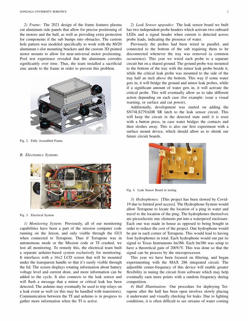
2) Frame: The 2021 design of the frame features plasmacut aluminum side panels that allow for precise positioning ofthe motors and the hull, as well as providing extra protectionfor components if the sub bumps into obstacles. The customhole pattern was modeled specifically to work with the 80/20aluminum t-slot mounting brackets and the custom 3D printedmotor mounts to allow for near-universal motor positioning.Pool test experience revealed that the aluminum corrodessignificantly over time. Thus, the team installed a sacrificialzinc anode to the frame in order to prevent this problem.
Fig. 2. Fully Assembled Frame
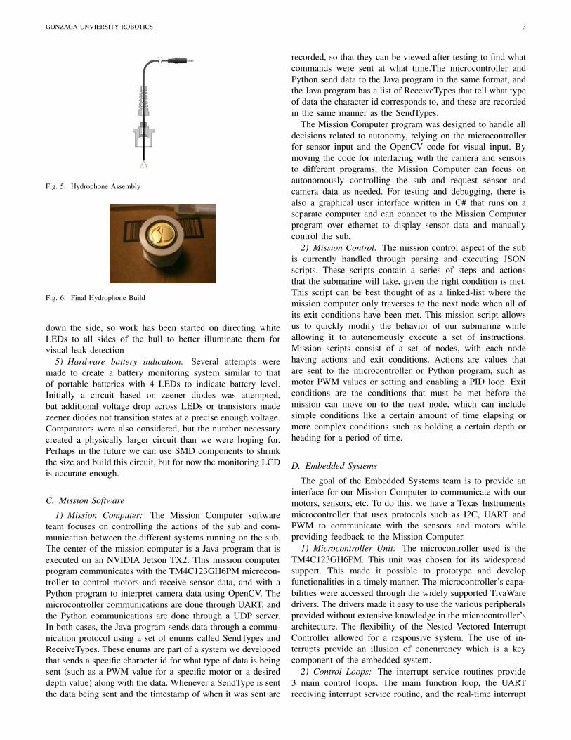
B. Electronics Systems
Fig. 3. Electrical System
1) Monitoring System: Previously, all of our monitoringcapabilities have been a part of the mission computer coderunning on the Jetson, and only visible through the GUIwhen connected to Terrapene. Thus if Terrapene was inautonomous mode or the Mission code or TI crashed, welost all monitoring. To remedy this, the electrical team builta separate arduino-based system exclusively for monitoring.It interfaces with a 16x2 LCD screen that will be mountedunder the transparent handle so that it’s easily visible throughthe lid. The screen displays rotating information about batteryvoltage level and current draw, and more information can beadded to the cycle. It also connects to the leak sensor andwill flash a message that a minor or critical leak has beendetected. The arduino may eventually be used to trip relays ona leak event as well (or this may be handled with transistors).Communication between the TI and arduino is in progress togather more information when the TI is active.
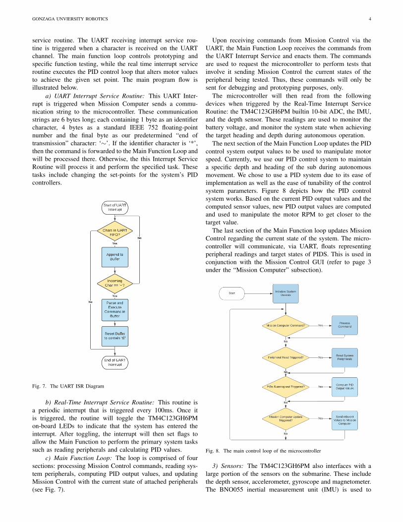
2) Leak Sensor upgrades: The leak sensor board we builthas two independent probe headers which activate two onboardLEDs and a signal header when current is detected acrossprobe leads, indicating the presence of water.
Previously the probes had been wired in parallel, andconnected to the bottom of the sub requiring them to bedisconnected whenever the tray was removed (a commonoccurrence). This year we wired each probe to a separatecircuit but on a shared ground. The ground probe was mountedto the bottom of the tray with the minor leak probe beside it,while the critical leak probe was mounted to the side of thetray half an inch above the bottom. This way if some watergets in, it will bridge the ground and minor leak probes, whileif a significant amount of water gets in, it will activate thecritical probe. This will eventually allow us to take differentaction depending on each case (for example: issue a visualwarning, or surface and cut power).
Additionally, development was started on adding theSN74LS279ADR SR latch to the leak sensor circuit. Thiswill keep the circuit in the detected state until it is resetwith a button press, in case water bridges the contacts andthen sloshes away. This is also our first experiment with asurface mount device, which should allow us to shrink ourfuture circuit boards.
Fig. 4. Leak Sensor Board in testing
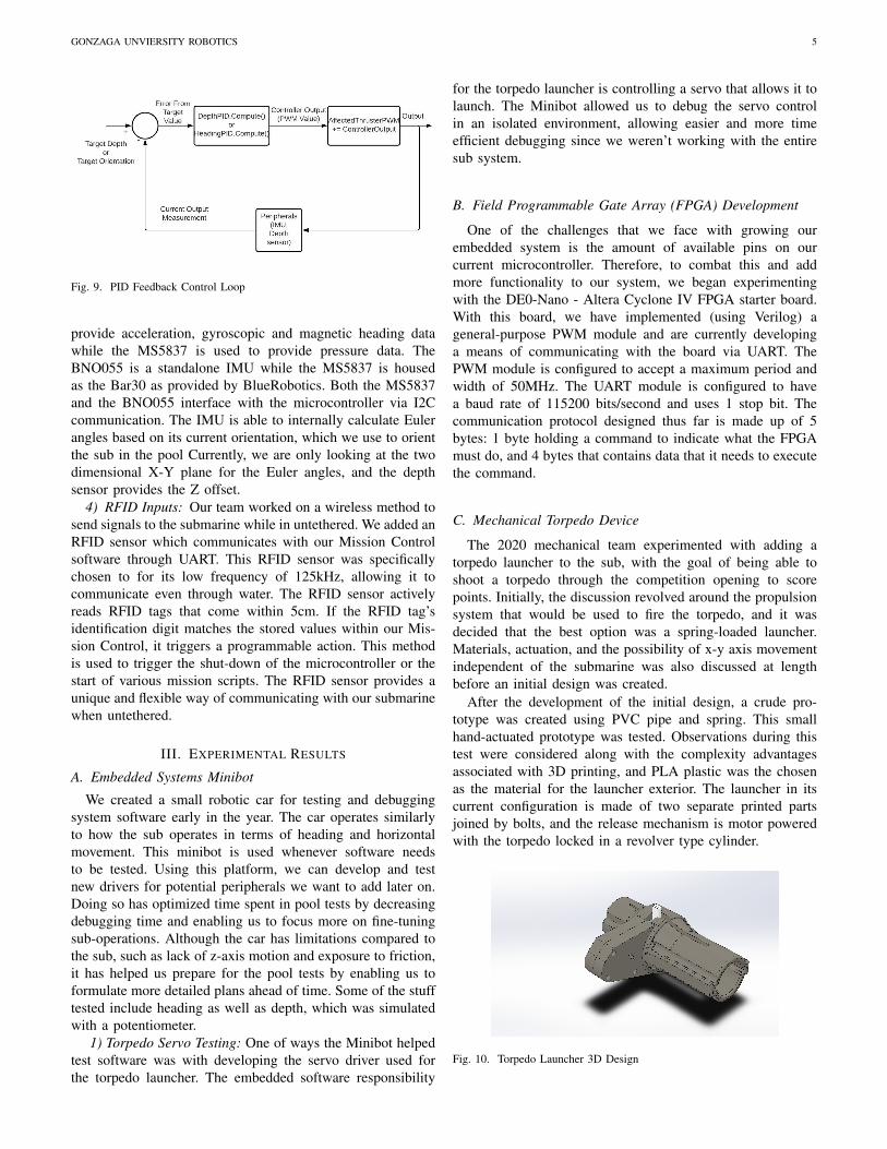
3) Hydrophones: [This project has been slowed by Covid-19 due to limited pool access]. The Hydrophone System wouldallow Terrapene to locate the location of a ping in water andtravel to the location of the ping. The hydrophones themselvesare piezoelectric mic elements put into a waterproof enclosure.Each one was made in house as opposed to being bought inorder to reduce the cost of the project. One hydrophone wouldbe put in each corner of Terrapene. This would lead to havingfour hydrophones in total. Each hydrophone would out put itssignal to Texas Instruments lm386. Each lm386 was setup tohave a theoretical gain of 200V/V. This was done so that thesignal can be process by the microprocessor.
This year we have been focused on filtering, and beganexperimenting with the MAX 286 integrated circuit. Theadjustible center-frequency of this device will enable greaterflexibility in tuning the circuit from software which may helpeventually earn more points with a random frequency duringcompetition.
4) Hull Illumination: Our procedure for deploying Ter-rapene after the hull has been open involves slowly placingit underwater and visually checking for leaks. Due to lightingconditions, it is often difficult to see streams of water coming
GONZAGA UNVIERSITY ROBOTICS 3
Fig. 5. Hydrophone Assembly
Fig. 6. Final Hydrophone Build
down the side, so work has been started on directing whiteLEDs to all sides of the hull to better illuminate them forvisual leak detection
5) Hardware battery indication: Several attempts weremade to create a battery monitoring system similar to thatof portable batteries with 4 LEDs to indicate battery level.Initially a circuit based on zeener diodes was attempted,but additional voltage drop across LEDs or transistors madezeener diodes not transition states at a precise enough voltage.Comparators were also considered, but the number necessarycreated a physically larger circuit than we were hoping for.Perhaps in the future we can use SMD components to shrinkthe size and build this circuit, but for now the monitoring LCDis accurate enough.
C. Mission Software
1) Mission Computer: The Mission Computer softwareteam focuses on controlling the actions of the sub and com-munication between the different systems running on the sub.The center of the mission computer is a Java program that isexecuted on an NVIDIA Jetson TX2. This mission computerprogram communicates with the TM4C123GH6PM microcon-troller to control motors and receive sensor data, and with aPython program to interpret camera data using OpenCV. Themicrocontroller communications are done through UART, andthe Python communications are done through a UDP server.In both cases, the Java program sends data through a commu-nication protocol using a set of enums called SendTypes andReceiveTypes. These enums are part of a system we developedthat sends a specific character id for what type of data is beingsent (such as a PWM value for a specific motor or a desireddepth value) along with the data. Whenever a SendType is sentthe data being sent and the timestamp of when it was sent are
recorded, so that they can be viewed after testing to find whatcommands were sent at what time.The microcontroller andPython send data to the Java program in the same format, andthe Java program has a list of ReceiveTypes that tell what typeof data the character id corresponds to, and these are recordedin the same manner as the SendTypes.
The Mission Computer program was designed to handle alldecisions related to autonomy, relying on the microcontrollerfor sensor input and the OpenCV code for visual input. Bymoving the code for interfacing with the camera and sensorsto different programs, the Mission Computer can focus onautonomously controlling the sub and request sensor andcamera data as needed. For testing and debugging, there isalso a graphical user interface written in C# that runs on aseparate computer and can connect to the Mission Computerprogram over ethernet to display sensor data and manuallycontrol the sub.
2) Mission Control: The mission control aspect of the subis currently handled through parsing and executing JSONscripts. These scripts contain a series of steps and actionsthat the submarine will take, given the right condition is met.This script can be best thought of as a linked-list where themission computer only traverses to the next node when all ofits exit conditions have been met. This mission script allowsus to quickly modify the behavior of our submarine whileallowing it to autonomously execute a set of instructions.Mission scripts consist of a set of nodes, with each nodehaving actions and exit conditions. Actions are values thatare sent to the microcontroller or Python program, such asmotor PWM values or setting and enabling a PID loop. Exitconditions are the conditions that must be met before themission can move on to the next node, which can includesimple conditions like a certain amount of time elapsing ormore complex conditions such as holding a certain depth orheading for a period of time.
D. Embedded Systems
The goal of the Embedded Systems team is to provide aninterface for our Mission Computer to communicate with ourmotors, sensors, etc. To do this, we have a Texas Instrumentsmicrocontroller that uses protocols such as I2C, UART andPWM to communicate with the sensors and motors whileproviding feedback to the Mission Computer.
1) Microcontroller Unit: The microcontroller used is theTM4C123GH6PM. This unit was chosen for its widespreadsupport. This made it possible to prototype and developfunctionalities in a timely manner. The microcontroller’s capa-bilities were accessed through the widely supported TivaWaredrivers. The drivers made it easy to use the various peripheralsprovided without extensive knowledge in the microcontroller’sarchitecture. The flexibility of the Nested Vectored InterruptController allowed for a responsive system. The use of in-terrupts provide an illusion of concurrency which is a keycomponent of the embedded system.
2) Control Loops: The interrupt service routines provide3 main control loops. The main function loop, the UARTreceiving interrupt service routine, and the real-time interrupt
GONZAGA UNVIERSITY ROBOTICS 4
service routine. The UART receiving interrupt service rou-tine is triggered when a character is received on the UARTchannel. The main function loop controls prototyping andspecific function testing, while the real time interrupt serviceroutine executes the PID control loop that alters motor valuesto achieve the given set point. The main program flow isillustrated below.
a) UART Interrupt Service Routine: This UART Inter-rupt is triggered when Mission Computer sends a commu-nication string to the microcontroller. These communicationstrings are 6 bytes long; each containing 1 byte as an identifiercharacter, 4 bytes as a standard IEEE 752 floating-pointnumber and the final byte as our predetermined “end oftransmission” character: ‘∼’. If the identifier character is ‘*’,then the command is forwarded to the Main Function Loop andwill be processed there. Otherwise, the this Interrupt ServiceRoutine will process it and perform the specified task. Thesetasks include changing the set-points for the system’s PIDcontrollers.
Fig. 7. The UART ISR Diagram
b) Real-Time Interrupt Service Routine: This routine isa periodic interrupt that is triggered every 100ms. Once itis triggered, the routine will toggle the TM4C123GH6PMon-board LEDs to indicate that the system has entered theinterrupt. After toggling, the interrupt will then set flags toallow the Main Function to perform the primary system taskssuch as reading peripherals and calculating PID values.
c) Main Function Loop: The loop is comprised of foursections: processing Mission Control commands, reading sys-tem peripherals, computing PID output values, and updatingMission Control with the current state of attached peripherals(see Fig. 7).
Upon receiving commands from Mission Control via theUART, the Main Function Loop receives the commands fromthe UART Interrupt Service and enacts them. The commandsare used to request the microcontroller to perform tests thatinvolve it sending Mission Control the current states of theperipheral being tested. Thus, these commands will only besent for debugging and prototyping purposes, only.
The microcontroller will then read from the followingdevices when triggered by the Real-Time Interrupt ServiceRoutine: the TM4C123GH6PM builtin 10-bit ADC, the IMU,and the depth sensor. These readings are used to monitor thebattery voltage, and monitor the system state when achievingthe target heading and depth during autonomous operation.
The next section of the Main Function Loop updates the PIDcontrol system output values to be used to manipulate motorspeed. Currently, we use our PID control system to maintaina specific depth and heading of the sub during autonomousmovement. We chose to use a PID system due to its ease ofimplementation as well as the ease of tunability of the controlsystem parameters. Figure 8 depicts how the PID controlsystem works. Based on the current PID output values and thecomputed sensor values, new PID output values are computedand used to manipulate the motor RPM to get closer to thetarget value.
The last section of the Main Function loop updates MissionControl regarding the current state of the system. The micro-controller will communicate, via UART, floats representingperipheral readings and target states of PIDS. This is used inconjunction with the Mission Control GUI (refer to page 3under the “Mission Computer” subsection).
Fig. 8. The main control loop of the microcontroller
3) Sensors: The TM4C123GH6PM also interfaces with alarge portion of the sensors on the submarine. These includethe depth sensor, accelerometer, gyroscope and magnetometer.The BNO055 inertial measurement unit (IMU) is used to
GONZAGA UNVIERSITY ROBOTICS 5
Fig. 9. PID Feedback Control Loop
provide acceleration, gyroscopic and magnetic heading datawhile the MS5837 is used to provide pressure data. TheBNO055 is a standalone IMU while the MS5837 is housedas the Bar30 as provided by BlueRobotics. Both the MS5837and the BNO055 interface with the microcontroller via I2Ccommunication. The IMU is able to internally calculate Eulerangles based on its current orientation, which we use to orientthe sub in the pool Currently, we are only looking at the twodimensional X-Y plane for the Euler angles, and the depthsensor provides the Z offset.
4) RFID Inputs: Our team worked on a wireless method tosend signals to the submarine while in untethered. We added anRFID sensor which communicates with our Mission Controlsoftware through UART. This RFID sensor was specificallychosen to for its low frequency of 125kHz, allowing it tocommunicate even through water. The RFID sensor activelyreads RFID tags that come within 5cm. If the RFID tag’sidentification digit matches the stored values within our Mis-sion Control, it triggers a programmable action. This methodis used to trigger the shut-down of the microcontroller or thestart of various mission scripts. The RFID sensor provides aunique and flexible way of communicating with our submarinewhen untethered.
III. EXPERIMENTAL RESULTS
A. Embedded Systems Minibot
We created a small robotic car for testing and debuggingsystem software early in the year. The car operates similarlyto how the sub operates in terms of heading and horizontalmovement. This minibot is used whenever software needsto be tested. Using this platform, we can develop and testnew drivers for potential peripherals we want to add later on.Doing so has optimized time spent in pool tests by decreasingdebugging time and enabling us to focus more on fine-tuningsub-operations. Although the car has limitations compared tothe sub, such as lack of z-axis motion and exposure to friction,it has helped us prepare for the pool tests by enabling us toformulate more detailed plans ahead of time. Some of the stufftested include heading as well as depth, which was simulatedwith a potentiometer.
1) Torpedo Servo Testing: One of ways the Minibot helpedtest software was with developing the servo driver used forthe torpedo launcher. The embedded software responsibility
for the torpedo launcher is controlling a servo that allows it tolaunch. The Minibot allowed us to debug the servo controlin an isolated environment, allowing easier and more timeefficient debugging since we weren’t working with the entiresub system.
B. Field Programmable Gate Array (FPGA) Development
One of the challenges that we face with growing ourembedded system is the amount of available pins on ourcurrent microcontroller. Therefore, to combat this and addmore functionality to our system, we began experimentingwith the DE0-Nano - Altera Cyclone IV FPGA starter board.With this board, we have implemented (using Verilog) ageneral-purpose PWM module and are currently developinga means of communicating with the board via UART. ThePWM module is configured to accept a maximum period andwidth of 50MHz. The UART module is configured to havea baud rate of 115200 bits/second and uses 1 stop bit. Thecommunication protocol designed thus far is made up of 5bytes: 1 byte holding a command to indicate what the FPGAmust do, and 4 bytes that contains data that it needs to executethe command.
C. Mechanical Torpedo Device
The 2020 mechanical team experimented with adding atorpedo launcher to the sub, with the goal of being able toshoot a torpedo through the competition opening to scorepoints. Initially, the discussion revolved around the propulsionsystem that would be used to fire the torpedo, and it wasdecided that the best option was a spring-loaded launcher.Materials, actuation, and the possibility of x-y axis movementindependent of the submarine was also discussed at lengthbefore an initial design was created.
After the development of the initial design, a crude pro-totype was created using PVC pipe and spring. This smallhand-actuated prototype was tested. Observations during thistest were considered along with the complexity advantagesassociated with 3D printing, and PLA plastic was the chosenas the material for the launcher exterior. The launcher in itscurrent configuration is made of two separate printed partsjoined by bolts, and the release mechanism is motor poweredwith the torpedo locked in a revolver type cylinder.
Fig. 10. Torpedo Launcher 3D Design
GONZAGA UNVIERSITY ROBOTICS 6
D. Hydrophones
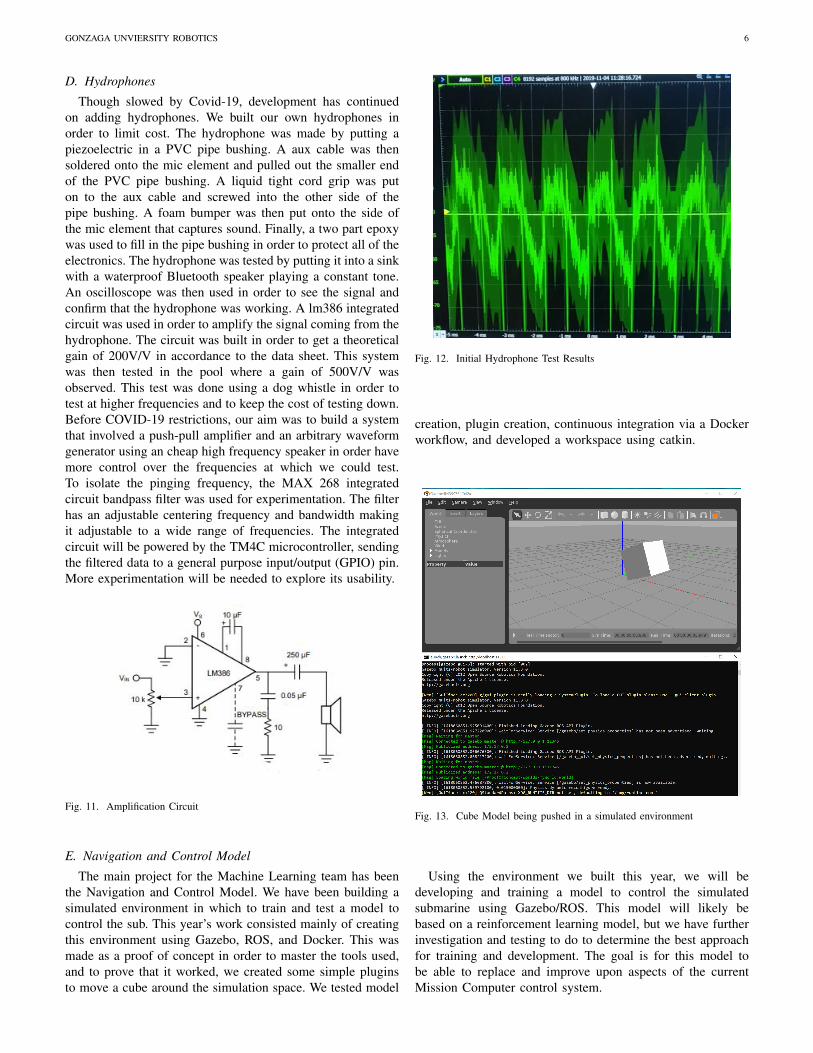
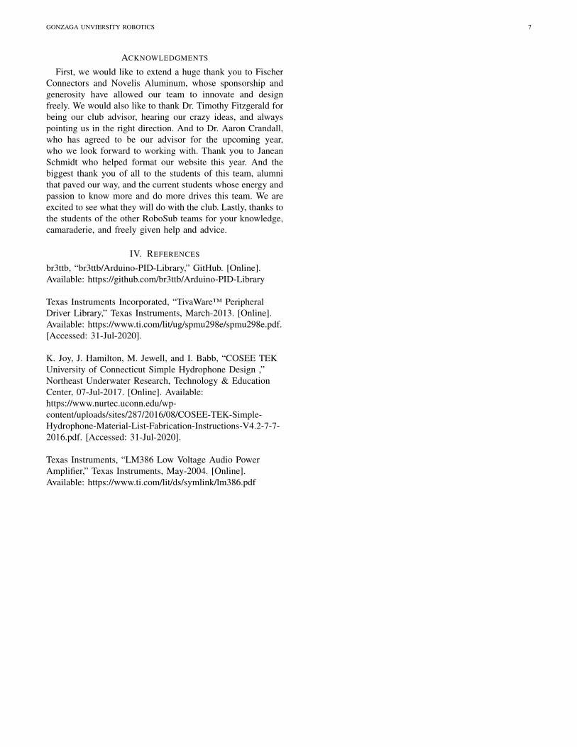
Though slowed by Covid-19, development has continuedon adding hydrophones. We built our own hydrophones inorder to limit cost. The hydrophone was made by putting apiezoelectric in a PVC pipe bushing. A aux cable was thensoldered onto the mic element and pulled out the smaller endof the PVC pipe bushing. A liquid tight cord grip was puton to the aux cable and screwed into the other side of thepipe bushing. A foam bumper was then put onto the side ofthe mic element that captures sound. Finally, a two part epoxywas used to fill in the pipe bushing in order to protect all of theelectronics. The hydrophone was tested by putting it into a sinkwith a waterproof Bluetooth speaker playing a constant tone.An oscilloscope was then used in order to see the signal andconfirm that the hydrophone was working. A lm386 integratedcircuit was used in order to amplify the signal coming from thehydrophone. The circuit was built in order to get a theoreticalgain of 200V/V in accordance to the data sheet. This systemwas then tested in the pool where a gain of 500V/V wasobserved. This test was done using a dog whistle in order totest at higher frequencies and to keep the cost of testing down.Before COVID-19 restrictions, our aim was to build a systemthat involved a push-pull amplifier and an arbitrary waveformgenerator using an cheap high frequency speaker in order havemore control over the frequencies at which we could test.To isolate the pinging frequency, the MAX 268 integratedcircuit bandpass filter was used for experimentation. The filterhas an adjustable centering frequency and bandwidth makingit adjustable to a wide range of frequencies. The integratedcircuit will be powered by the TM4C microcontroller, sendingthe filtered data to a general purpose input/output (GPIO) pin.More experimentation will be needed to explore its usability.
Fig. 11. Amplification Circuit
E. Navigation and Control Model
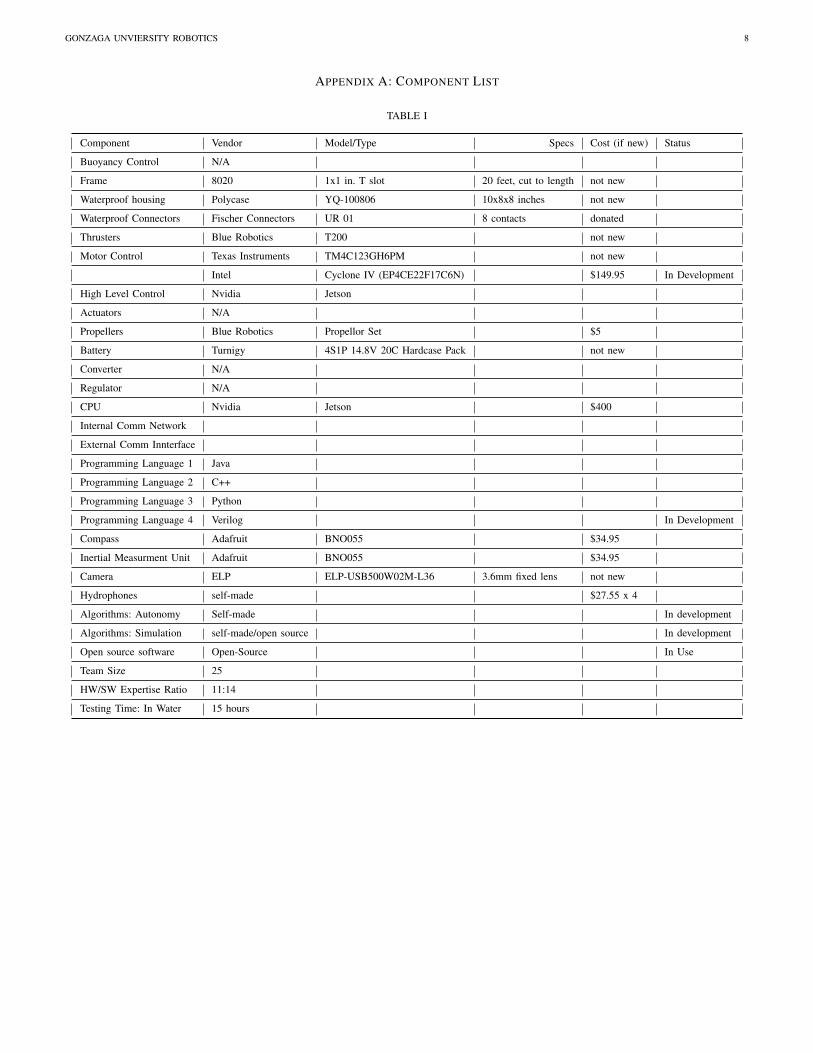
The main project for the Machine Learning team has beenthe Navigation and Control Model. We have been building asimulated environment in which to train and test a model tocontrol the sub. This year’s work consisted mainly of creatingthis environment using Gazebo, ROS, and Docker. This wasmade as a proof of concept in order to master the tools used,and to prove that it worked, we created some simple pluginsto move a cube around the simulation space. We tested model
Fig. 12. Initial Hydrophone Test Results
creation, plugin creation, continuous integration via a Dockerworkflow, and developed a workspace using catkin.
Fig. 13. Cube Model being pushed in a simulated environment
Using the environment we built this year, we will bedeveloping and training a model to control the simulatedsubmarine using Gazebo/ROS. This model will likely bebased on a reinforcement learning model, but we have furtherinvestigation and testing to do to determine the best approachfor training and development. The goal is for this model tobe able to replace and improve upon aspects of the currentMission Computer control system.
GONZAGA UNVIERSITY ROBOTICS 7
ACKNOWLEDGMENTS
First, we would like to extend a huge thank you to FischerConnectors and Novelis Aluminum, whose sponsorship andgenerosity have allowed our team to innovate and designfreely. We would also like to thank Dr. Timothy Fitzgerald forbeing our club advisor, hearing our crazy ideas, and alwayspointing us in the right direction. And to Dr. Aaron Crandall,who has agreed to be our advisor for the upcoming year,who we look forward to working with. Thank you to JaneanSchmidt who helped format our website this year. And thebiggest thank you of all to the students of this team, alumnithat paved our way, and the current students whose energy andpassion to know more and do more drives this team. We areexcited to see what they will do with the club. Lastly, thanks tothe students of the other RoboSub teams for your knowledge,camaraderie, and freely given help and advice.
IV. REFERENCES
br3ttb, “br3ttb/Arduino-PID-Library,” GitHub. [Online].Available: https://github.com/br3ttb/Arduino-PID-Library
Texas Instruments Incorporated, “TivaWare™ PeripheralDriver Library,” Texas Instruments, March-2013. [Online].Available: https://www.ti.com/lit/ug/spmu298e/spmu298e.pdf.[Accessed: 31-Jul-2020].
K. Joy, J. Hamilton, M. Jewell, and I. Babb, “COSEE TEKUniversity of Connecticut Simple Hydrophone Design ,”Northeast Underwater Research, Technology & EducationCenter, 07-Jul-2017. [Online]. Available:https://www.nurtec.uconn.edu/wp-content/uploads/sites/287/2016/08/COSEE-TEK-Simple-Hydrophone-Material-List-Fabrication-Instructions-V4.2-7-7-2016.pdf. [Accessed: 31-Jul-2020].
Texas Instruments, “LM386 Low Voltage Audio PowerAmplifier,” Texas Instruments, May-2004. [Online].Available: https://www.ti.com/lit/ds/symlink/lm386.pdf
GONZAGA UNVIERSITY ROBOTICS 8
APPENDIX A: COMPONENT LIST
TABLE I
Component Vendor Model/Type Specs Cost (if new) Status
Buoyancy Control N/A
Frame 8020 1x1 in. T slot 20 feet, cut to length not new
Waterproof housing Polycase YQ-100806 10x8x8 inches not new
Waterproof Connectors Fischer Connectors UR 01 8 contacts donated
Thrusters Blue Robotics T200 not new
Motor Control Texas Instruments TM4C123GH6PM not new
Intel Cyclone IV (EP4CE22F17C6N) $149.95 In Development
High Level Control Nvidia Jetson
Actuators N/A
Propellers Blue Robotics Propellor Set $5
Battery Turnigy 4S1P 14.8V 20C Hardcase Pack not new
Converter N/A
Regulator N/A
CPU Nvidia Jetson $400
Internal Comm Network
External Comm Innterface
Programming Language 1 Java
Programming Language 2 C++
Programming Language 3 Python
Programming Language 4 Verilog In Development
Compass Adafruit BNO055 $34.95
Inertial Measurment Unit Adafruit BNO055 $34.95
Camera ELP ELP-USB500W02M-L36 3.6mm fixed lens not new
Hydrophones self-made $27.55 x 4
Algorithms: Autonomy Self-made In development
Algorithms: Simulation self-made/open source In development
Open source software Open-Source In Use
Team Size 25
HW/SW Expertise Ratio 11:14
Testing Time: In Water 15 hours
GONZAGA UNVIERSITY ROBOTICS 9
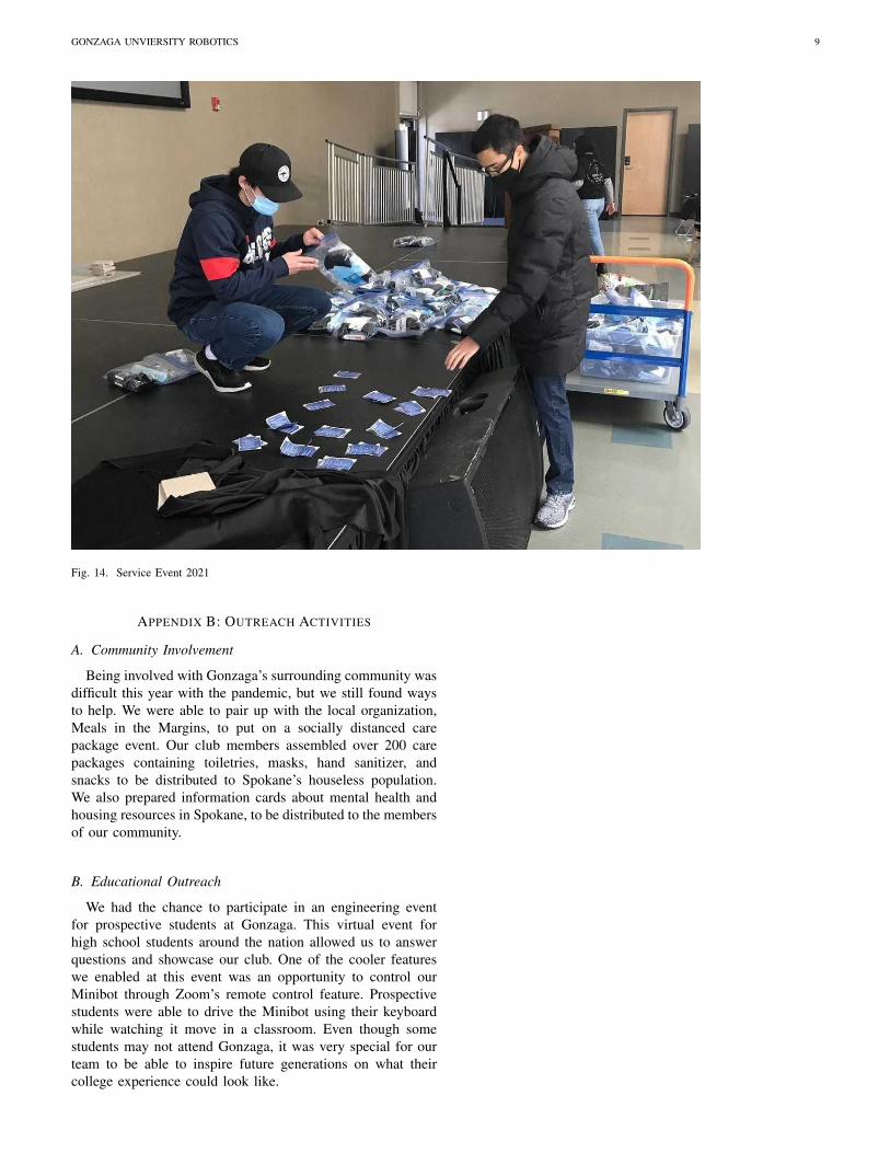
Fig. 14. Service Event 2021
APPENDIX B: OUTREACH ACTIVITIES
A. Community Involvement
Being involved with Gonzaga’s surrounding community wasdifficult this year with the pandemic, but we still found waysto help. We were able to pair up with the local organization,Meals in the Margins, to put on a socially distanced carepackage event. Our club members assembled over 200 carepackages containing toiletries, masks, hand sanitizer, andsnacks to be distributed to Spokane’s houseless population.We also prepared information cards about mental health andhousing resources in Spokane, to be distributed to the membersof our community.
B. Educational Outreach
We had the chance to participate in an engineering eventfor prospective students at Gonzaga. This virtual event forhigh school students around the nation allowed us to answerquestions and showcase our club. One of the cooler featureswe enabled at this event was an opportunity to control ourMinibot through Zoom’s remote control feature. Prospectivestudents were able to drive the Minibot using their keyboardwhile watching it move in a classroom. Even though somestudents may not attend Gonzaga, it was very special for ourteam to be able to inspire future generations on what theircollege experience could look like.


![Framework Gonzaga[1] 1](https://img.pdfslide.us/doc/110x75/546fc284b4af9fb71d8b45d0/framework-gonzaga1-1.jpg)