Embed Size (px)
Citation preview
lGOVERNMENT OF PAKISTAN
MINISTRY OF' COMMUNICATIONSNATIONAL HIGHWAY AUTHORITY
Gonstruction ofPeshawar Northern Bypass (Package-2)
(Km Z+OOO to Km 19+500)
BIDDING DOCUMENTSVOLUME-III
- PARTICULARSPECIFICATIONS- SPECIAL PROVISIONS
XII NATIONAL ENGINEERING SERVICES PAKISTAN (PVT) LIMITEDylx NESPAK HOUSE, r-C, Block N, Model 'l'own Extension, p.O. Box 1351. Lahore pakisun
-
. {
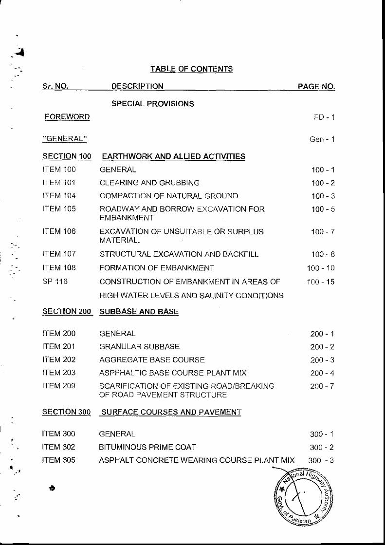
TABLE OF CONTENTS
Sr. Nq DESCRIPTION PAGE NO.
SPECIAL PROVISIONS
FOREWORD
"GENERAL"
sEcTroN 100tTEl\,1 100
tTEl\it 101
ITEM 104
r ' rEM 105
lTEl\il 106
]TEM 107
ITEM 1OB
SP 116
EARTHWORK AND ALLIED ACTIVITIES
GENERAL
CLEARING AND GRUBBING
COMPACTION OF NATURAL GROUND
ROADWAY AND BORROW EXCAVATION FOREI\,,IBANKI\,4ENT
EXCAVATION OF UNSUITABLE OR SURPLUSI\,1ATERIAL.
STRUCTURAL EXCAVATION AND BACKFILL
FORMATION OF EMBANKMENT
CONSTRUCTION OF EMBANKI\,1ENT IN AREAS OF
HIGH WATER LEVELS AND SALINITY CONDITIONS
SUBBASE AND BASE
GENERAL
GRANULAR SUBBASE
AGGREGATE BASE COURSE
ASPPHALTIC BASE COURSE PLANT IV]IX
SCARIFICATION OF EXISTING ROAD/BREAKINGOF ROAD PAVTN/EN I S TRUC I JRt
SURFACE COURSES AND PAVEMENT
100-1
100-2
100-3
100-5
100-7
100-B
100 - 10
100 - 15
SECTION 2OO
ITEM 2OO
ITEM 201
ITEM 202
ITEM 203
tTEt!1 209
SECTION 30O
200-1
200-2
200-3
200-4
200-7
300 - 1
300-2
300-3
tTEtM 300
ITEM 302
tTEt\4 305
a
GENERAL
BITUMINOUS PRIME COAT
ASPHALT CONCRETE WEARING COURSE PLANT IV]IX
ii
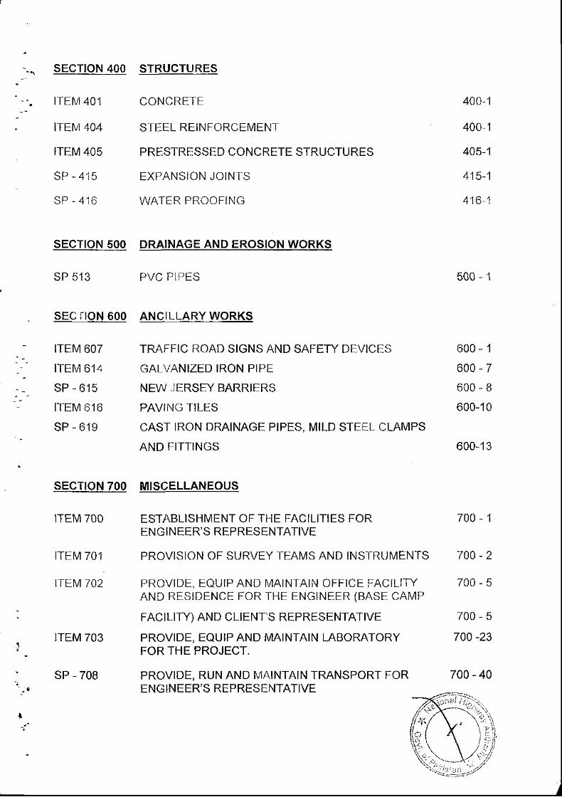
SECTION 4OO STRUCTURES
tTEN,140'1
ITEIVI 404
ITEM 405
sP - 415
sP - 416
sEcTtoN 500
sP 513
sEc iroN 600
tTEtv 607
lTEt\l 614
sP - 615
ITEM 6 16
sP - 619
sEcTtoN 700
ITEM 70O
ITEM 70,1
ITEM 702
600-1
600-7
600-B
600-10
600-13
700-1
700-2
700-5
700-5
700 -23
700 - 40
CONCRETE
STEEL REINFORCEMENT
PRESTRESSED CONCRETE STRUCTURES
EXPANSION JOINTS
WATER PROOFING
400,1
400 1
405-1
415-1
416 1
DRAINAGE AND EROSION WORKS
PVC PIPES
ANCILLARY WORKS
TRAFFIC ROAD SIGNS AND SAFETY DEVICES
GALVANIZED IRON PIPE
NEW JERSEY BARRIERS
PAVING TILES
CAST IRON DRAINAGE PIPES, MILD STEEL CLAMPS
AND FITTINGS
MISCELLANEOUS
ESTABLISHMENT OF THE FACILITIES FORENGINEER'S REPRESENTATIVE
PROVISION OF SURVEY TEAMS AND INSTRUIV]ENTS
PROVIDE, EQUIP AND IV]AINTAIN OFFICE FACILITYAND RESIDENCE FOR THE ENGINEER (BASE CAMP
FACILITY) AND CLIENT'S REPRESENTATIVE
PROVIDE, EQUIP AND MAINTAIN LABORATORYFOR THE PROJECT.
PROVIDE, RUN AND MAINTAIN TRANSPORT FORENGINEER'S REPRESENTATIVE
500-1
l_ITEM 703
sP - 708

ouoMfuoj
t
FOREWORD
SPECIAL PROVISIONS
The following Special Pfovisjons are amendmenis' cotrigenda' delellons an0
addi t ionsto theGenera |Spec i f ica t ions ' issuedbytheNat iona lHighwayAutho| i ty
in December 1998, laid down in Volume ll ltems of Padicular Specifications are
reoresented bv the corresponding itern nurnber of the General Specifications to
which an amendment, a corrigendum' a deletion or an addition relates \'Vhen a
ne\ /1 / i temhasbeencons ideredfor thePro jec t , i i i sprecededbythe le t tersSP
(Special Provision) followed by a three digit number which corresponds to the
o- rber next to tne las athibuted number i1 the class of work series
Wheneverare ference ismadein theSpec ia lProv is ion inregardtoanymanua|or
a test designation either of the American Society for Testing and Materials
(ASTM), the American Association of State Highway and I ransportation Officials
(AASHTo), Asphalt lnstitution, Federal Highway Specifiaations or any other
recognized national organization and the number on other identification
representing lhe year of adoption or latest revision is omitted' it shall mean the
Specifications, manual or test designation in effect on the day the Notice to
Proceed with the Works is issued to the Contractor'
No seDarate items are provided for haul or transporiation and these are deemed to
be part of the relevant pay item of the Contract BilL of Quaniities
n;j 4ir:_\\---\"r"
Q;,-\'';
-tvu=tN:r9
GENERAL
1. INTRODUCTION
lnsert before para 1.1 the following:-
a) DESCRIPTION OF THE WORKS
The proposed Peshawar Northern Bypass, a four lane dual carriageway'
takes off from Peshawar toll plaza of M-1 and ends near Jamrud on N-5
passing throLlgh North of Peshawaf City lt wiil provide connection with
Motorway network, reduce tfaffic congestion in the city and also facilitate
the through iraffic of Afghanistan. Length of proposed Peshawar Northern
Bypass is about 32 kms There are three contract packages of the proiect
Package No.1 consists of construction of 7 6 km four lane dual carriageway
and all allied structures i.e two (2) bridges and eight (8) drainage culverts'
and Package - 2 consisis of construction of 11 6 Km'
The work shall include Granular lvtaterial Platform, Earth\'vork for the
embankment, Granular Subbase' Aggregate Base Course' Asphaltic Base
Course and Asphaltic Wearing Course. The consiruction of Bridges'
Drainage Structures, Retaining Structures, Drains' Ditches and Protection
Works are also included in the Scope of Works All construction matenal'
labour, equipment and accessories shall be provided by the Contractor'
The Contractor is to provide facil i t ies for
also provide facil i t ies for the Engineer's
Lhese lac i l l tes a re to De prov ided as
according to l ists in the Contract
his workforce. The Contractor will
Represeniative. Basic services for
well as furniture and equlpmenl
from Charsadda Road and
b) GENERAL DESCRIPTTON OF THE AREA
Peshawar Northern Bypass (Package-2) starts
Ends near Warsak Road.
/ :t-(,#$(Gen-l
C) MATERIALS SOURCES
Fill material and aggregaies for use in the \,vork shall be provided by the
Contractor, where not available from excavation within the work, from
sources to be identified and established by the contractor who will be
responsible for surveying and testing to prove the extent and suitability of
rnaterials, for land and royalty/malkana cosis, for access roads, site
facllites, siripping overburden, sepafation of materials, processing and
transpori of materials, reinstatement, insurance and all other costs. All costs
shall be considered as included within the rates inserted for the items
included in the Bill of Quantities.
Test results on materials, obtained by the Engineer during preparatron of
the Contract, are available for inspection, on application to the Ernployels
Repfesentative.
Testinq
In para 4, at end of first sentencein line 3, add the following:
Certificate of Compliance."
1.1
", except as provided in ltem 1.21,
1.2 Trial Section
1.3
At the end, add new items as below
Certificate of Compliance
A Certificate of Compliance shall be furnished prior to the use of any
material where these SDecifications warrant such certificate to be furnished.
ln addition, where permissible under these Specifications, the Engineer
may permit the use of certain materials or assemblies prior io sampling and
testing. if accompanied by a Certif ica e of Compltanca Th ,{biit
rl -* ' :Gen-2
Compliance shall be furnished with each lot, clearly identified in the
certificate.
All material used on the basis oi Certificate of Cofirpliance may be sampled
and tested at any time. A Certificate of Compliance however shall not
relieve the Contractor of his other obligations under the Contract for
incorporaijng materlals in the Work. Such materials shall conform io the
requirements of the felevant Contract Drawings and Specifications.
The Employer reserves the right to refuse the permission for the use of
materials on the basis of a Certificate of Compliance.
The form ol the Certificate of Compliance and its disposition shall be as
directed by the Engineer.
lrriqation Canals, Channels. Water-courses. Drains and Sewers etc
The Contractor shall co|ir.rct his operations so as to offer the ieast possible
obstruction for maintaining flow in irrigation canals, channels, watercourses,
drains and sewers. The Contractor shall observe all rules and regulations of
appropriate authorities fegarding the interrupiion and majntenance of flow in
irrigation canals, channels, watercourses, drains and sewefs and shall save
harmless and indemnify the Employer in respect of all claims, demands,
proceedings, damages, costs and expenses whatsoever arising out of or in
relation to any such construction, operations or interferences with irrigation
flows.
The Contractor shall maintain alternate channels wherever temporary
reloaation of irrigation channels, water-courses, drains and sewefs, is
required or where his operations disrupt the irrigation flow, without any
compensation from the Employer.{
Access and Canal Roads
, ien-3

lf the Contractor finds rt necessary or selects to use exisiing canal roads'
the Contractor shall make all necessary arrangements and obiain all
permits from the provincial lrrigation Department for the Lrse of such canal
roads. The Cohtractor shall observe all rules and regulations of the
lrrigation Department regarding the use of said canal roads The cost of
maintaining all necessary safeiy measures and iemporary struciures and
making any necessary repairs, replacements or similar operations and all or
any other costs required by reason of his use of such canal roads snall De
borne by the Contractor and he shall save harmless and indemnify the
Employer in respect of all claims' demands, proceedings, damages' costs'
charges and expenses whatsoever arising out or in felation to any such
operatjon or interference.
The Conhactor shall submit a plan for approval of the Engineer, indicating
the road network to be used for haulage and other works
I
1.6 Makinq Good Damaqe to Services. Earthworks etc-
The Contractor shall make good, at his own cost, all damages to telephone'
and etectric cables including underground installations or wires' sewers'
water, or other pipes excepi where Authority' Employer or Private Party
owning or responsible fof the same elects to make good such damages'
All injury to the sufface of the land' to the beds of water-courses' protection
banks, river beds, etc. where disturbed by the works (other than where
specifically ordered by the Employer) shall be repaired by the Contractor or
the Authorities concetned at the Coniractois expense All such maklng
good shall be as approved by the Employef
Gen-4
1.7 Safetv Precautions
The Contractor shall adequately provide safety, healthcare and welfare to
his persons and prevent the damage to works, material and equipment for
the purpose of or in connection with the Contract.
t
$Gen-5
SECTION
EARTHWORK AND ALLIED ACTIVITIES
EARTHWORK AND ALLIED ACTIVITIES
SECTION 1OO GENERAL
100.1
1,OO.2
DESCRIPTION
ln line 2, delete "earth" and insert "soil"
SOIL INFORMATION
ln para 2,line 2, delete "earth" and insed "soil".
ln para 2, line 3, after "requirements", add "in particular the borrow
pits".
100.4 REMOVAL OF EXISTING OBSTRUCTIONS
i) In line 5, after "bridges", add "walls, buildings and roads"'
i i) In line 7, after "item", delete "exists" and add "appears in the
Bill of Quantities"
100 ' 1
ITEM 101 CLEARING AND GRUBBING
101.3.1
't 01.3.2
Measurement
Deleie para 2.
Pavment
In lLne 4, afier "original" insert "level and"
I t o z
ITEM ,I 04 COMPACTION OF NATURAL GROUND
104.1 DESCRIPTION
Delete complete paragraph and replace with following:
Prior to the natural/original ground, the cleared and grubbed su'Jace(i.e. the surface after cleafing and grubbing), stripped surface afterstripping and the excavated surface after excavation shall becompacted. Pfior to commencement of embankment construction inaccordance with these Specifications, as shown on the Drawings oras directed by the Engineer's Representative. The compaction shallbe carried out through a written order of the EngineelsRepresentar ive.
CONSTRUCTION REQUIREMENTS
Delete top paragraph and replace with:
104.2
The natural ground/cleared and grubbed, stripped and excavatedsurfaces shall be broken up, ploughed, scarified, all sods andvegetable matters removed and compacted to a depth of 200 mmand to the specified density as given below:
104,2.1 COMPACTION OF ORIGINAL GROUND SURFACE IN AREAS OFHIGH WATER LEVELS AND SALINITY
Delete complete paragraph and replace with:
"Refer to Special Provision SP 116 for material and constructionrequirements under these conditions".
104.3.1 MEASUREMENT & PAYMENT
Delete complete paragraph and replace wiih:
The quantity io be paid for shall be the number of square metersdirected to be compacted and accepted by the Engineer'sRepresentative for payment. The restoration of original ground levelswith fil l material after execution of ltem 104 shall not be paidseparately and shall be deemed to be included in this pay item.
The area determined asContract unit price for the
provided above shall be paid for apay item listed below and shown i
1 0 0 l
of Quantities wh;ch price and payment shall constitute fullcompensation for all the costs necessary for the proper completion ofthe work prescribed in this Section.
1 0 0 , 4
ITEM 105 ROADWAY AND BORROW EXCAVATION FOR EMBANKMENT
f05.1 DESCRTPTTON
In line 4, after 'ail excavation" add "after stripping of top soil (ifrequired)".
In l ine 8, add at the end:
"li shall include the only sultable material for fi l l in the ef.rbankmentor backfil l ing of Siructure All unsuitable or surplus material isprovided for in iiem 106. Excavation for structures is covered underitem 107. Excavation for diversion / widening of water-courses isinc luded."
105.2.1 Road Wav Excavation
r )
i i)
Delete "Road Way" from the title and insert "Roadway."
Delete para 2 and replace with:
"Roadway Excavation shall further be classified as "ComrnonExcavation" and "Rock Excavation" The classification shallinclude all the materials of whatever rature encounteredexcept where these are unsuitable or surplus to requirementsas in i tem 106" .
a) common Excavationi i i )
ln line 7, insert "silts" before "sands."
105,2.2 BorrowExcavation
l n para 3 , l ine 4 add a t the end:
"ln particular they wil l be left in a safe, free draining condii ion. In allareas any topsoil previously removed shall be reinstated unlessotherwise instructed by the Engineer's Representative".
CONSTRUCTION REQUIREMENTS
i) ln Dara 4. add at the end:
"Where appropriate drainage shall be reinstated
105.3
1 0 0 - 5
i i)
i i i )
In para B, delete first sentence and lnsert "borrow maierialshall not be laken wlthrn two (2) kilometers, feach fromdownstream of any hydraulic siructure."
After last para insert the following:
a) The excavated matefial approved for f i l l under any itemof the B i l l o f Quant i t ies sha l l be used in the manner asdescrlbed Llndef the item of work.
b) lf it is unsuitable material, it shall be disposed of at thedesignated location in the manner as directed by theEngineer's Representative.
lf the material is surplus to the fll l requirements of theProject, it shall be disposed of at the location in amanner approved by the Engineer's Representative.
ln rock excavation any area over-excavated in thesubgrade shall be reinstated as directed by theEngineefs R-p.esentative at the cost of the Contractor.For disposal oi excavated rock material sameprocedure shall be followed as described above for"Common Excavation".
o)
\ 9*:
),,i,100"6
ITEM 106 EXCAVATION OF UNSUITABLE OR SURPLUS MATERIAL
106.1
106 .3 .1
106.3.2
DESCRIPTION
Ai the end, add foliowing para:
This also includes the matefial of existing structures and obstructionswhich are fequired to be removed as shown on Drawings or asdirected by the Engineefs Representative.
Measurement
ln para 3, l ine 1 , de le te "Nos. 106a, 106b, 106c and 106d" .
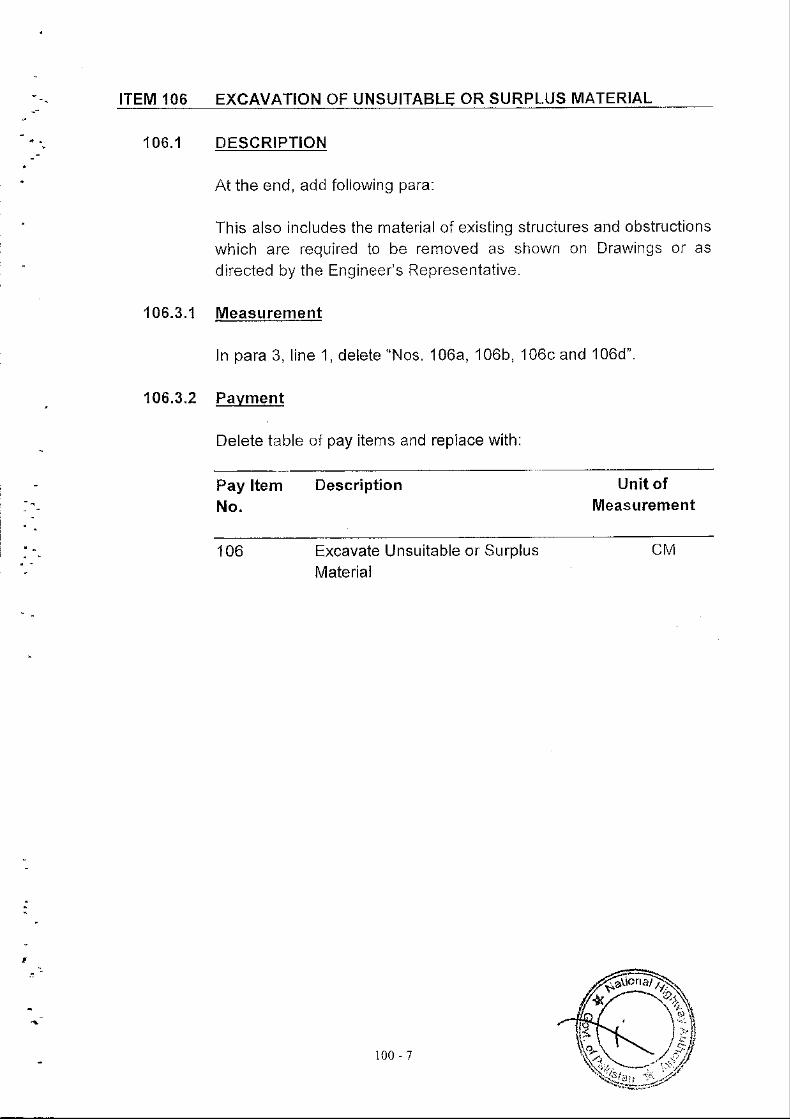
Pavment
Delete table of pay items and replace with:
Pay ltemNo.
Description Unit ofMeasurement
'106 Excavate Unsuitable or SurplusMaterial
c l\,1
(*
)j1 0 0 - 7
ITEM 107 STRUCTURAL EXCAVATIONS AND BACKFILL
,107.1 DESCRTPTTON
In l ine 12, add at the end:
Excavation below original ground and fil l ing with granular fi l l shall bepaid under th is i iem. Common f i l l ing and backf i l l ing shal i be pa idLrf def item 108 for all common fil l ing and backfil l ing above the leveof t l re or ig ina l groL, ' ld l r re .
107.2.3 CommonBackf i l l
In line 2, between "allowed" and "subject" insert "on condition that thematerial requirements in item '108.2 are followed and".
107.3.1 Preparation of Foundations of Footings
ii) In para (ii), l ine 2, delete "special, care" and replace with ", specialcare".
At the end of add para (ii i) as follows:
Foundation material on which structure is to be placed shall becompacted to 95% modified MSHTO T-180, unless oiherwisedirected by the Engineeis Representative. ln case unsultablematefial is encountered at foundation level, it shall be removed to thedepth and extent as directed and replaced with suiiable material ofthe type as determined by the Engineer's Representative.
107.3.2 Excavation in Embankments
In para 3, line 2, after "payment", add "except where granular backfil lis specified by the Engineer's Representative".
107.3.3 Backf i l l
Delete para (h., and substitute as under:
"No backfil l shall be placed against any concrete or masonrystructure until permission is obtained from the Engineer'sRepresentative and preferably until the concrete or masonrystructure has been in place fourteen (14) days, or uniil test cylindersshow the strength to be 80% of the 28 days cylinder strength of
",. ;.
1 0 0 - 8
concrete as per table 401-1. The backfi l l ing shall be carried out onboth sides of the structure simultaneously. All buried concretrsufaces shall be bitumen coated Cost of which shall be included ln
backfi l l ing".
iD
( i i i )
At the end, add Para (i) as follows:
Any temporary backfil l or platform constructed by iheContractor for piling purposes or for any other wofk item shalibe subsequently femoved by the Contractor without anypayment as difected by the Engineer's Repfesentative.
107.4.1 Measurement
a) Structural Excavation
In line 2, between "position' and "computed" insert "below topsoil".
ln sub-para (1), Iine 4, add the at the end:
"Neat lines of footings or foundations shall mean the .Lrterfaces of footings or foundations excluding lean concrete."
At the end, add the following para:
No separate payment shall be made for compaction ofexcavated foundation under structures.
iD
iiD
,)
1 0 0 , 9
ITEM 108 FORMATION OF EMBANKMENT
' 108 .1
'toa.2
DESCRIPTION
ln iine 6, add at the end "The work shall aiso include the compaction,trimming and shaping of the side slopes as shown on the plans andremoval of any excess fil l as directed by the Engineer'sRepresentative, prior to placement of top soil on slopes of iheembankment where requi red" .
MATERIAL REQUIREMENTS
Delete ihis entire item and replace with:
Material for embankment shall consist of suitable material excavatedunder ihe foregoing ltems '105 and J07 and approved by theEngineer's Representative's. Borrow material however, shall only beused when there is no suitable maierlal available from the roadwayor structural excavation.
Wet excavated material which will be sLritable when dry andapproved by the Engineer's Representaiive shall first be alloweddry before being placed in the embankment
The material under this section shall conform to the followingSpecifications:
a) The Contractor shall use AASHTO Class A-1, A-2, A-3, A-4,soil as specified in AASHTO M-145 or other material approvedby the Engineer's Representative.
b) The material for embankment, except the top 30cm, shalJhave a min imum soaked C.B.R. va lue of 5 .0 per cent un iessotherwise siated on the Drawings. The C.B.R. shall bedetermined in accordance wiih AASHTO T-193 at a max. drydensity, AASHTO T - 180 corresponding to the requlredcompaction zone of the embankment. For top 30cm, however,the CBR shall not be less than 8.0 per cent determined asabove at 95 per cent laboratory max. Dry density.
i fto
c) In case sandy material (P.1. < 4) is usedformation, it shall be properly confined withplasticity index value from 4 to 10 asEngineer's Represeniative.
for embankmenta material havingapproved by the
t\lrl
1 0 0 - 1 0
q ) In areas subject to flood and prolonged inundation of thee.nbankmeft, such as at bridge sites, the material used lnemDankment, unless rock, shall be AASHTO Class A1 (a),A1(b) and A-2-4 soils. Other sols may be used with thewritten consent of the Engineer's Representative andprovision of suitable protection to the embankment slopes asdirected by the Engineer's Representative.
For the pLrrpose of embankment and subgrade constructionthe following type of soil shall be considered as unsuitablematerials:
1)
2)3)4 )
6)
lvlaterial from soil AASHTO ciassification group of Aoand 47.Ivaterial from swamps, marshes and bogs;Peat, logs, stumps and perishable materials;Material susceptible to spontaneous combustion;
Materials having a moisture conient greater than themaximum permitted for such maierials in the contractor as directed by the Engineers Representativeorganic Soils.
108.3,1 Formation of Embankment with Borrow common Material
f) The moisture content of the soil at the time of compactionshall be uniform and shall be such that the soil can becompacted to the specified density and approved by iheEngineer's Representative. The moisture content shall be asdirected by the Engineefs Representative, as determinedfrom a test section and moisture density test (AASHTO T-'lB0Method D) done on each type of soil to be used in theconstruction of the work to delermine the maximum density,the optimum moisture content and the mojsture rangerequired for the soil to achieve the desired compaction andappfoved by the Engineefs Representative. The soil shall becompacted at oDtimum content with 1 1% tolerance.
In para 1, last line, after "approved" add "for each materialsource or borrow area."
iD Delete para 5 "The compactionequipment" and replace with :
o f the embankment . . . . .
)'Qi;;,1 0 0 - l l
"The compaciion of the embankment shall be carried out aithe designated optimum moisture content with I 1olo toleranceconsistent wjth the available compacting equipment. Informing the embankment, the Contractor shall take steps toensure that the work can be drained free of rain water, and heshall make due allowance in the height and width of the workfor swelling or shrinkage."
In para 6, llne 6, after the word "disklng" add "and scarifying".
In lasi pafa, add at the end:
i i i )
rv)
"ln order to prevent erosion of the slopes the Conlractor shallcompact the trimmed slopes to the required density prior tolaying top soll or as directed by the Engineefs Representative.
108.3.2 Formation of Embankment with Rock Material
r) lr para 1 lrne a, deleie "than .
i i) In para 2, l ine 2, delete "clean small spells,"
'108.3.3 For]nation of Embankment on Steep Slopes
Delete 1"r para and replace with:
"Where an embankment is to be constructed against an existingslope of 1 vertical to 5 horizontal or steeper, hill sides, existingshoulders or where new fil l is to be placed and compacted againstexisting pavement or where embankment is to be built along one halfthe width at a time, the existing slope shall be benched. Thehorizontal dimension of benches shall be greater than half the widthof the compacting equipment in use except where this would result inave ica l d imension at thebackof the bench of morethan60cmsinwhich case ihe horizontal dimension may be reduced.
The compact ion of benches shal l be as per Clause 108.3.1 of theGeneral Specif ications.
No measurement shall be made of the material cut from the existingslope, re-compacted at the same place or reused elsewhere forbenching purpose. Filting against the slope will be calculated on thevolume of fi l l placed against the original slope.
Existing slope in ihe context of this clause includes a partially
100- 12
constructed embankment but does not inciude the side of trenchexcavation.
108.3.4 Eefmation of Embankments on Existinq Roads
Delete line 6 after the "Engineer" and replaced with:
"The material declared suitable will be measured under relevant itemand ihat dec lared unsui tabe, wi l l be measured under i tem '106,
un ess a sepa 'ate pay i tem appedrs iF Bi l l o f OuaTt i t ies .
108,3,5 Formation of Embankments in Water Loqqed Areas
Delete entire para and replace with:
This work shall be performed as stipulated in SP 1 17.
108.3.6 Genera lRequi rement
Delete entire 2nd Para and replace with:
As a result of settlement, if an embankment requires theadditional material upto 30cm thjckness to bring it up to therequired grade level, the top of the embankment shall beprepared as per requirement of Sub-Grade preparation asstated in item No. 109. No separate payment shall be made tothe Conlractor for the scarification, removal and replacing orreworking of existing material to a depth as directed by theEngineer's Representative, unless a separate pay itemaopears in the Bill oI Quantities.
ii) After the last paragraph, add the following:
Embankmeni fi l l ing shall be brought up and compacted overthe full width of ihe embankment of one carriageway in oneoperation in layers parallel with the sub-grade level. At no timeshall any part of the embankment width under onecarriageway be left more than one layer lower than any otherpart of the embankment width.
Shoulder construction shall be brought up simultaneously withthe pavement construction.
In order to prevent water penetration into the paveme
100 - 1- l
during construction, shouldefs and median construction shallbe brought up simultaneously wiih the pavement constructionwhenever the transverse slope of the subgrade slopesdownwards towards the median. The filJ behind abutmentsand wjng walls of all bridges, pipes slab and box culverts shallbe deposited in well-compacted, horizontal layers notexceeding iwenty (20) cm in thickness to the density 100percent of max. Dry density as per AASHTO T1B0 (D).
i l i ) Af ier i tem 108.3.6, add i tem 108.3 T "Tr ia l Sect ion" as fo l lows:
108.3-7 Trial Section
Before starting the fil l ing of lhe embankment the Contfactorshall construct trial sections of 500 m or as directed by theEngineer's Representative in 2 iayers depth for each soiltype/source proposed for use as fil l material. The soils used inthe trials shall be the same as those intended to be used forthe formation of embankment and the compacting equipmentshall be same that the Contractor will use tor the main work.
-fhe construclion of embankment with any type of solllmaterial
source shall be subject to written approval of the Engineer'sRepresentative after the triai section made for that parliculartype of soil/material source.
The object of these trials shall be to determine the optimummoisture content and the relationship between the number ofpasses of compacting equipment and density obtained for thesoil types under trial and for the verification of the soil typeitself. No separate payment will be made for this work, whichshall be required as a subsidiary obligation of the Contractorunder Pay i tem Nos. 108a, 1 0Bb or 108c, as ihe case may be.
108.4.2 Pavment
In Sub-Clause c, Formation of Embankment from RoadwayExcavation, line 2, delete "form" and replace with "from".
ii) ln table of pay items, description of pay item 108a, line 2,delete "form" and reDlace with "from".
Hisi\
1 0 0 - 1 4
SP 116 CONSTRUCTION OF EMBANKMENT IN AREAS OF HIGH WATERLEVELS AND SALINITY CONDITIONS
116.1
116.2
DESCRIPTION
This work shall consist of the formation of embankment in areas ofsoft / weak foundations; compaction of natural ground shall not bepossible as speaified in item 104 and also in areas of high watertable. This also include ihe wet areas which cannot be dried byscarifying or other measures and exhibit moderate to severe heavingof surface during proof-rolling.The embankment shall consist of a working platform of the granularmaterial followed by the embankment fi l l material and eadhendowels provided at toe of the embankment, all constructed inaccofdance with these specifications and the specifications for otherwork items involved and in conformity with the lines, grades, sectionsand dimensions shown on the drawings or as dlrected by theEngineer's Representative.
MATERIAL REQUIREMENTS
116.2 .1 Subqrade/Embankment
The subgrade/embankment material shall be as per Clause 108.2 ofGeneral Specifications.
116.2.2 GranularMater ia l P la t form
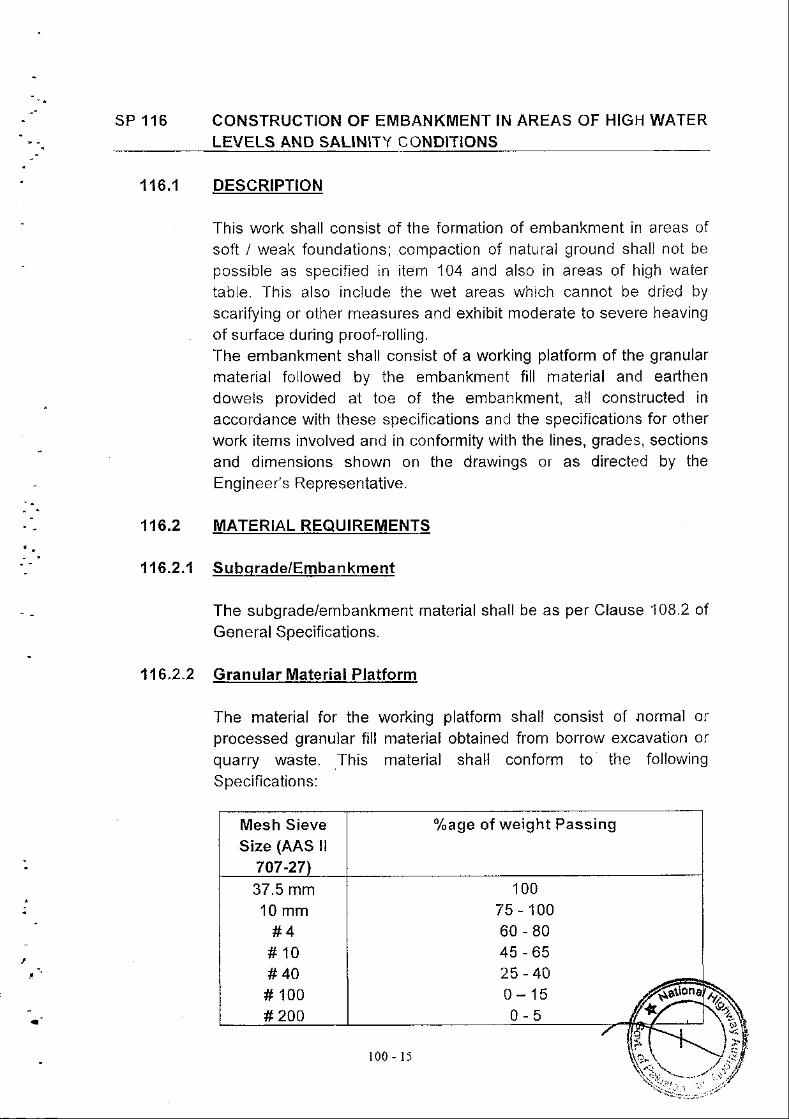
The material for the working platform shall consist of normal orprocessed granular fi l l material obtained from borrow excavation orquarry waste. This material shall conform to the followingSpecifications:
Mesh SieveSize (AAS ll
7 07 -271
%age o f we igh t Pass ing
37.5 mm10 mm
#4#10#40# '100
# 200
10075 - 10060-8045-6525-400-150-5
ffi-\\r-,t*- -
'1 0 0 , 1 5
q
i'il
The selected material shall be of such grad ng so that intrusion rntothe working platform maierial of subgfade or naiural ground surfacematefial is not allowed.
For following the above, this condition to be met it will be requiredthat the following raiio is to be checked and followed:
D15 - (Granular F i l l lMater ia l )
D85 - (Natural Ground l\i laterial)
DBS and D15 mean the practical diameters corresponding to B5%and 15% respectively, passing (by weight) in a grain size analysis.
116.2.3 Earthen Dowels
1 16.3
The material for earlhen dowels shall be any soil obtained fromborrow excavation or any other source as approved by theEngineer's Representative having a plasiicity index of more than 6. lishould be free oI organic and other deieterious substafces.
CONSTRUCTION REQUIREMENTS
116.3 . ' l S u bq rad e /Em ba n kment
The subgrade/embankment above the granular material platformshall be compacted to 95% AASHTO T-180 D regardless of zone ofembankment within which falls.
116.3.2 GranularMater ia l P la t form
Prior to laying of granular matefial platform, the pond/water ioggedafea upon which embankment are to be placed, shall have beendfied and drained or kept drained of all surface waier prior tocommencing of fi l l and all clearing and grubbing shall have beenperformed, manually if necessary in accordance with the relevantspecifications.
Construction of the granular fi l l layer shall proceed from one end ofthe soft area by using the granular fi l l as afil l transport. The thickness of the granulaf
ramp for further granulfil l working pla
prescribed shail be as shown on the Projecl s\z\ J5
'/*91 0 0 - 1 6
drawrngs or as
by ihe Engineer's Representativ€ and the width shall be thaa of theembankmenl or part as directed by the Engjneer's Representative.The placement and compaction of the working platform inclLldingboxng matera l shai l be carr ied out by the use of appropr ia te l iEhteqLripment, in layers, if necessary. The placement, spreading andcompaction of the Granular lvlaterial Platform shall be carried out byusing light equipment. The top 15 cm of the platform shali becompacted to at Least 90% AASHTO T - 180 density.
In ihose areas of high watef levels and salinity wlth soft subsoils andwhere embankments are high such as approach fil ls to structures,special pfovisions shall be made to measure and determine likely fi l lsettlements which may occur. These preconditions are necessary inorder to specify particulaf construction procedures which may benecessary and to establish the time at which the paven'lent structLlrecan be placed to avoid cracks & subsidence of these layers.
In particular, additional compaction of the fil l material and itsadequate protection shall be required to prevent underscore and therisk of "collapse" settlement.
At locations where granular material platform is used as detour road,Contraclor shall maintain its line and grade. This rnaintenance mayrequife replenishing of granular material for remedying the sinking ofgranular material platform or loss of material due to traffic. No extrapayment, under this item, shall be made to the Contractor fof re-working, re-instatement, replacement of granular material which hasbecome slushy or replenishing of gralular malerial fol whatsoeverreason.
MEASUREMENT AND PAYMENT
The quantities measured against this item as shown on lhe drawingswith respeci to line and grades shall be paid for at the contract unitprice for the pay items llsted below and shown in the Bill ofQuantities. These prices and payrnents shall constitute full paymentand compensation for providing including hauling, processing,placing at site and compacting as specified, replenishing granularmaterial for remedying loss of material due to traffic and sinking ofgranular material platform during construction or during use asdetour road, labour and other costs related to the completion ofworks in all respects.
On completion and approval of granular material platfo
116.4
"i' -1 0 0 - 1 7
paymeni for pay item SP 1l6a shall be made to the Contractor.Balance 2syo payment for pay item SP.116a shall be made to theContractor only when the gran,rlar material platform is no morerequired to serye as detour road and it has been re-worked, re-instated or replaced as directed by the Engineer's Representativeand is re-approved and ready to receive oncoming layer ofembankment .
Pay ltemNo.
Descr ip t ion Uni t o fMeasurement
SP'1 16a
116b
ct\,1
ct\,1SP
The payment for formation of embankmeni other than item SP 116shall be paid under item 108 of Bill of Quantitles.
Formation of Granular Material Platform
Formation of Ea(hen Dowels
1 0 0 - l 8
sEcTtoN - 200
SUBBASE AND BASE
SUBBASE AND BASE
SECTION 2OO GENERAL
200.1
200.2.1
DESCRIPTION
In para 1 , l ine 2 , de le te " , base, " and inser t " , c fushed
aggregate base course,
Sampl inq and Tes t ing
In para 3, line 5, after "...... Testing and Material (ASTN,4)", insertthe word "or" for particular materials or procedures, the BritishStandards Institutlon,"
2 0 0 - I
ITEM 201 GRANULAR SUBBASE
201.2 Material Requirements
In para (a):
r )
I )
In second line, delete "A,
ln the tab le o f Grad lngde le te "g rad ing A" .
B and C" and
Requ i rements
replace with "B".
for Subbase l\,4atefial,
J2 0 0 ' 2
ITEM 202 AGGREGATE BASE COURSE
202.'l
202.2
DESCRIPTION
Add at the end:
The word "Aggregate Base" wherever appearing in ltern 202 shouldbe read as "Crushed Aggfegate Base Course".
Material Requirements
In para (a):
(1) In l ine 2, de le te " or 8" .
(2) In the table of Grading Requirements for AggregateBase MaterjaJ, deJete "grading B'
In para (e), l ine 2, delete "the material shall ......as determinedby AASHTO T-Bg & 90. ' and replace by the following:
"the portion of fi l ler, including any blended material, passingNo.40 mesh sieve shall have a liquid lirnit not more than 25and a plasticity index not more than 4 when tested inaccordance wiih AASHTO T-89 & T-90. '
i i )
202.4.2 Pavment
Replace the pay item table as follows:-
Pay ltemNo.
Description Unit ofMeasurement
242 Crushed Aggregate Base Course CM
2 0 0 - 3
ITEM 203 ASPHALTIC BASE COURSE PLANT MIX
203.2 .2 Asbha l t i cMater ia l
ln line 2, delete "40-50,60-70 or B0-100' and replace with "60-70"
203"2,3 Asohalt Concrete Base Course Mixture
In l lne 2, de le te "Class A and/of ' .
ln the table of Combined Aggregate Grading Requiremenis(Table 203-1), delele "grading for Class A".
i i )
203.2.4 Job lvlix Formula
After para 3, add the following:
The combined gfadation should produce a smooth curveapproximaiely paralleling grading band limits for designated mix. Thejob-mix formula with allowable tolerances for a single test thenbecomes the job control grading band. lf application of job-mixtolerances results in a job control grading band outside the mastergrading oand, the full tolerances shall stil l apply.
Prior to linal approval, the proposed job mix, with a bitumen contental ihe permissible upper percentage limit determined in JlVlF, shali becompacted to refusal (750 to 900 blows) and the resulting alr voids lnthe mix shall not be less than 3%.
203.3.7 Spreadinq and F in ish inq
Delete para 2 and repiace with the folloMng:
Care shall be taken to ensure that matefial is properly compacted upto ioint positions. lf this is not done or results in misshapen sufaceon a layer, the Engineer may instruct unacceptable matefial to be cutback before laying the adjacent material. Joints in superimposedlayer of asphaltic material must be offset longitudinally by at least 2mand transversely by at least 30 cm. Longitudinal joints in wearingcourse shall, after cutting back, be of good alignment and preferablycoincident with the position of carriageway markings. Except wherelaying in echelon, joints in wearing course shall be cut back to avertical face and Tack coated. Kerb faces, ironwork and the li
2 4 0 - 4
contact with wearing course shall be tack coated prlor to layingwearing course.The ouier edges of wearing course shall be cut back to a goodalignmeni, parallel with the road alignment. This will require a smalladditional width of wearing coufse to be laid.
The Contractor should allow, within his bid rates, fof this additionalwidth and for all cutting back of wearing course which wil l not bemeasured for payment. Tack coating of vertical faces wil l not bemeasured for PaYment.
203.3,1 0 Surface Tolerances
At the end, add the following:
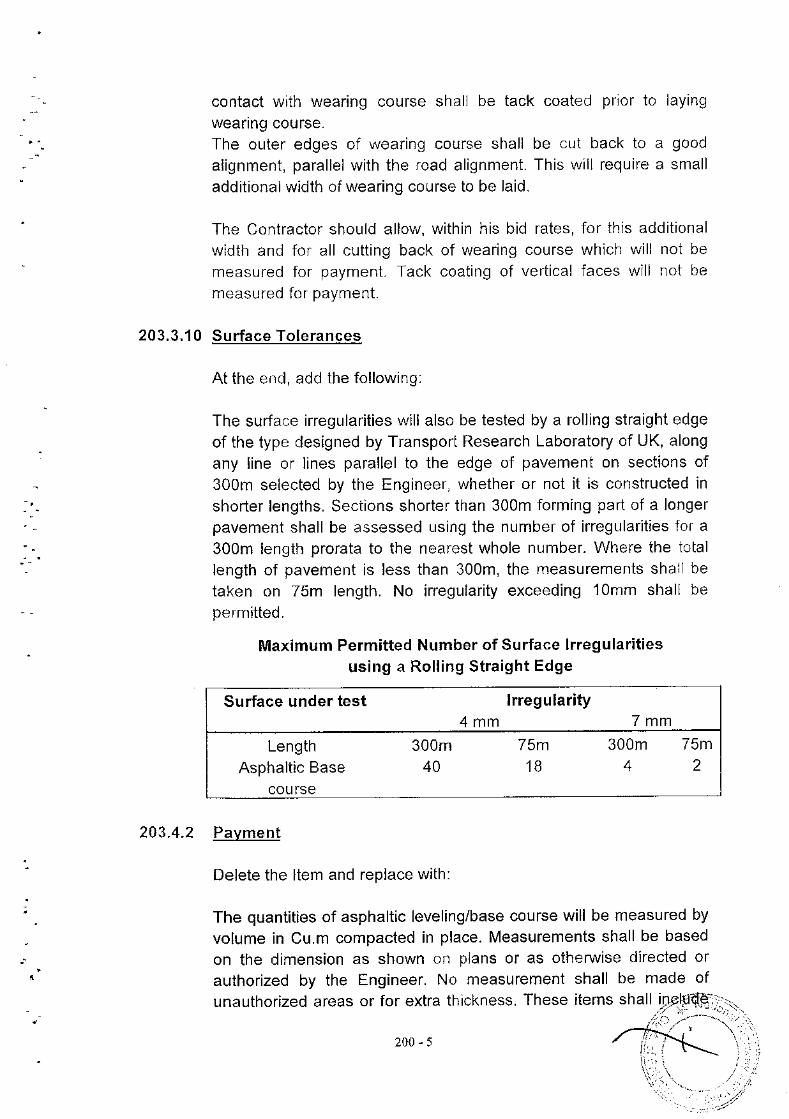
The surface irregularities will also be tested by a rolling straight edgeof the type designed by Transport Research Laboratory of UK, alongany line or lines parallel to the edge of pavemeni on sections of300m selected by the Engineer, whether or not it is construcied inshorter lengths. Seciions shorter than 300m forming pari of a longefpavement shall be assessed using the numbef of irregularities fof a300m length prorata to the nearest whole number. Where ihe iotallength of pavement is less than 300m, the measurements shall betaken on 75m length. No irregularity exceeding 1omm shall bepermitted.
Maximum Permitted Number of Surface lrregularitiesusing a Rolling Straight Edge
Surface under test lrregularity4mm 7mm
Length 300m 75m 300m 75mAsphaliic Base 40 1B 4 2
course
203.4.2 Pavment
Delete the ltem and replace with:
The quantities of asphaltic leveling/base course will be measured byvolume in Cu.m compacted in place. Measurements shall be basedon the dimension as shown on plans or as oiherwise directed orauthorized by the Engineer. No measurement shall be made ofunauthorized areas or for extra thickness. These items shall i
2 0 0 - 5
the furnishing of all materials including asphalt additive or antstripping agent, if allowed by the Engineer to meet requiremenis ofJMF; the drying and screening of aggregates, the mixing ofbituminous material with the aggregates and ihe placing, furnishingand compaction of the mixed material.
Quantities of asphalt concrete mixed, wasted or disposed of in amanner noi called for undef the Speclfications or remaining on handafter completion of the work will not be paid for. The quantii iesdetermined as measured above shall be paid or at the Contraci unitprice for the particular pay items listed below and shown in the Bill ofQuantities, which prices and payment shall constitute fullcompensation for all costs necessary for proper completion of thework prescribed in the item:
Pay ltemNo.
Description Uni t o fMeasu rement
2O3 a
203 b
CM
CM
Asphaltic Base Course Plant Mix
Asphaltic Levelling Course Plant
(Class B)
N,4ix (Class B)
200 6
ITEM 209
209.1
209.2
209.3.2
SGARIFICATION OF EXISTING ROAD/BREAKING OF ROADPAVEMENT STRUCTURE
DESCRIPTION
i) In line 4, delete "aggregate base" and replace with "pavementst ructure.
In line 4, delete "base materlal" and feplace with"embankment/ pavement structure".
ln line 6, delete "crushed stone base aggregate" and replacewith "embankmenUpavement structure".
ii)
i i i )
CONSTRUCTION REQUIREMENTS
ln parc 2, line 2, delete "off' and replace with "of'.
Pavment
In line 4, after "equipment," add "disposal as directed by the
Engineer , "
200-7
sEcTtoN 300
SURFACE COURSES AND PAVEMENT
SECTION 3OO
SURFACE COURSES AND PAVEMENT
GENERAL
ln para 1, line 5, after "...... Testing and Material (ASTM)", insert thewords "or, for paniculaf materials or procedures, the British SiandardsInstitution,".
3 0 0 - 1
ITEM 302 BITUMINOUS PRIME COAT
302.3 CONSTRUCTION REQUIREMENTS
ln para 1, delete sentences '1 to 3 and replace with:
Prior to the application of prime coat, loose material shall be removedfrom the surface and cleaned bv rnechanica blowers and handbrooms. The applicaiion is prohibited when the weather is foggy orrainy or when the atmospheric temperature is below fifteen (15)degree C unless otherwise difected by the Engineer. On a soil surfaceor granular sub-base or crashed aggregates base course, the cleanedsurface shall be given a light application of water and allowed to dry toa surface-dry condition before prime coat is applied
- : .
1"R\
^^Y+3 0 0 - 2
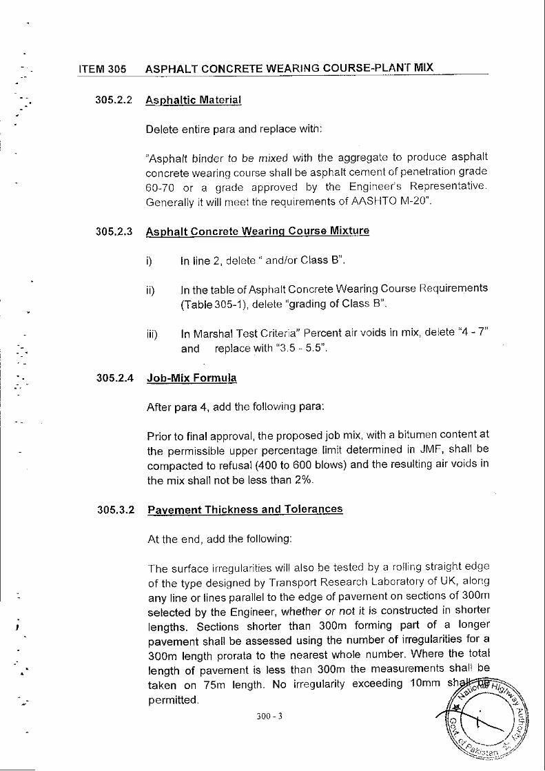
ITEM 305 ASPHALT CONCRETE WEARING COURSE-PLANT MIX
305.2.2 Asphal t icMater ia l
Delete entire para and replace with:
"Asphalt binder to be mjxed wiih the aggregaie to produce asphalt
concrete wearing coLlrse shall be asphali cernent of penetration grade
60-70 of a grade approved by the Engineefs Representative
Generally it wil l meei the requirements of AASHTO M-20"
305.2.3 Asphalt concrete Wearinq Course Mixture
In line 2, delete " and/or class 8".
ln the table of Asphalt Concrete Wearing Course Requirements(Table 305-l), delete "grading of Class 8".
ln Marshal Test critefla" Percent air voids in mix, delete "4 - 7"and replace with '3.5 - 5.5".
305.2.4 Job-MixFormula
After para 4, add the follo\,ving Para:
Prior to final approval, the proposed job mix, with a bitumen content at
the permissible upper percentage lim;t determined in JN'4F, shall be
compacted to refusal (400 to 600 blows) and the resuliing air voids in
the mix shall not be less than 2%.
305"3,2 Pavement Thickness and Tolerances
At the end, add ihe following:
The surface irregularlties will also be iested by a rolllng straight edge
of the type designed by Tfansport Research Laboraiory of UK, along
any line or lines parallel to the edge of pavement on sections of 300m
selected by the Engineer, whether or not it is constructed in shorterlengths. Sections shorter than 300m forming part of a longerpavement shall be assessed using the number of irregularities for a
3O0m length prorata to the nearest whole number' Where the total
tength of pavement is less than 30Om the measufements shall be
taken on 75m length. No irregulariiy exceeding 1omm sh
r)
ii)
iiD
\-\
:)?'
ki.;1,,
permitted.300 l
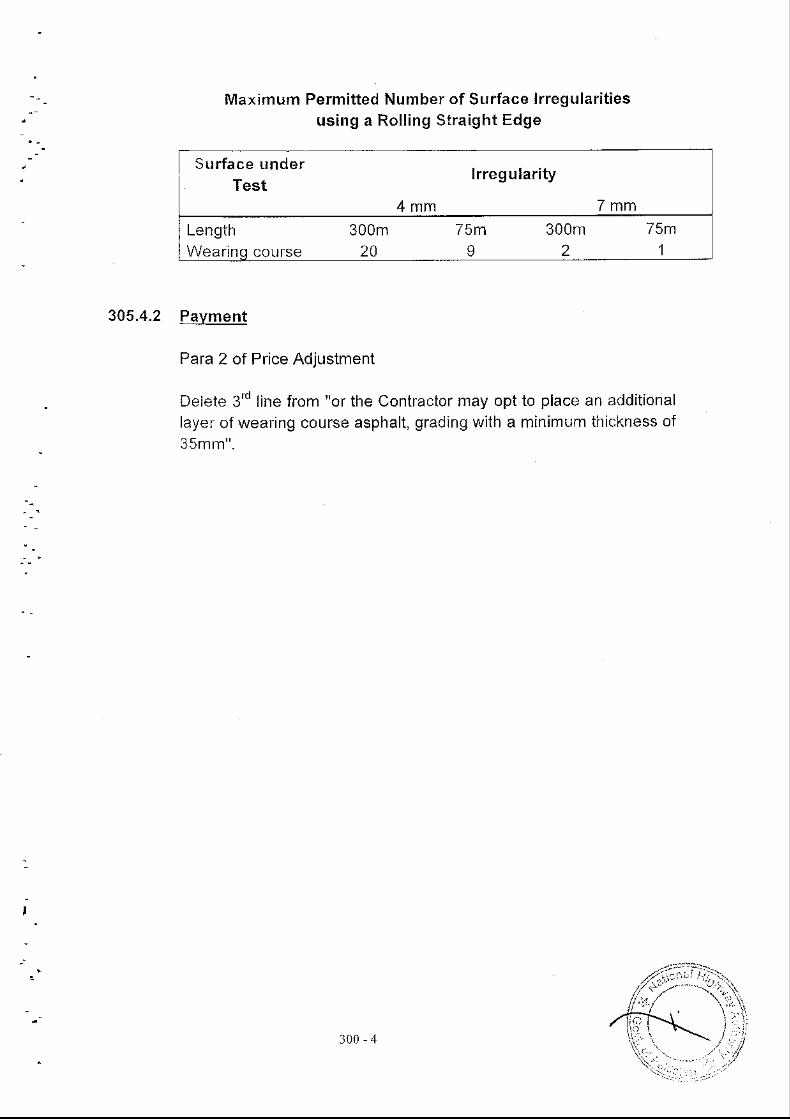
Maximum Permitted Number of Surface lrregularitiesus ing a Rol l ing St ra ight Edge
305.4.2 Pavment
Para 2 of Price Adjustment
Delete 3'd line from "or the Contfactor may optlayer of wearing course asphalt, gradlng with a35mm".
to place an additionalminimum thiakness of
I
Surface underTest
lrregularity
4mm 7mmLength 300m 75m 300m 75mWearinq course 20 I 2 1
3 0 0 - 4
SECTION 4OO
STRUCTURES
)i(T
STRUCTURES
SECTION 40O CONCRETE
401.'l DESCRIPTION
Paragraph 1 , l ine 3 be iween "aggregates" and 'a l l in accordance" , add
"and chemical admixtures as may be required".
Add the following io 401.1 at the end of paragraph 1.
Tolerances on dimensions and seftinq out
Concfete siructures in their finai state musi present the same dimensions asshown on Drawings and comply with the following tolerances:
Tolerances (TL) on every dimension (d), (length, width, diagonal orthickness) will be given by the formula:
A.3
A.3.1
TL = 0.25 (d)l/ 'zwhere TL and d are given in mmThe tolerances (TL) will have to be within:
- a minimum of 1omm- and a maximum of 70 mm
4.2 Tolerances of plumb (TA) for aTA = 0.5 (h)"" where TA and h
Tolerances of flatness
height h is given by the following formula:are grven In mm
Ordinary surface form finish
- Unit flatness buili up by a 2 m ruler should allow space less than15mm behveen the concrete and the ruler.
- Local flatness build up by a ruler of 0.20m shouldthan 6mm between the concrete and the ruler.
Class 1: Surface form finish:)-
4.3.2
400-l
allow a space less
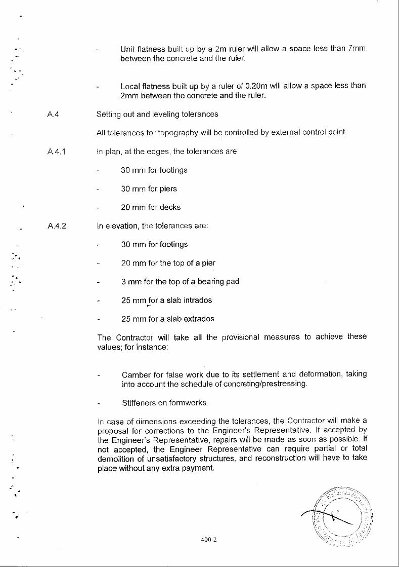
Unii flatness built up by a 2m ruler will allow a space less than /mmbehr'r'een the concrete and ihe ruler.
- Local flatness built up by a ruler of 0.20m will allow a space less than2mm befuveen the concrete and the ruler.
Setting out and leveling tolerances
All tolerances fof topography will be conifolled by external control poirlt.
ln plan, at the edges, the tolerances are:
30 mm for footings
30 mm for piers
20 mm fof decks
elevation, the tolerances are:
30 mm for footings
20 mm for the top of a pier
3 mm for the top of a bearing pad
25 mm for a slab intrados
- 25 mm for a slab extrados
The Contractor will take all the provisional measures to achieve thesevalues; for instance:
- Camber for false work due to its settlement and deformation, takinginto account the schedule of concreting/prestressing.
- Stiffeners on formworks.
In case of dimensions exceeding the toletances, the Contractor \\/i l l make aproposal for corrections to the Engineeis Representative. lf accepied bythe Engineer's Representative, repairs will be made as soon as possibie lfnot accepted, the Engineer Representative can require partial or totaldemolition of unsatisfactory structures, and reconstruction will have to takeplace without any extra payment.
4.4.1
4.4 .2 ln
400 2
B
401.1.1
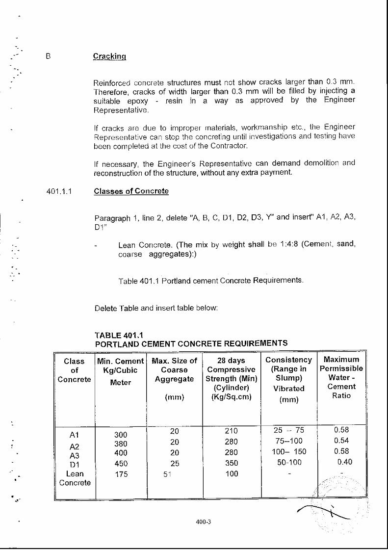
crackinq
Reinforced concrete structures must not show cracks larger than 0 3 mmTherefore, cracks of width larger than 0.3 mm will be filled by injecting asuitable epoxy - resin in a way as approved by the EngineerRepresentative.
lf cracks are due to improper materials, workmanship etc., the EnglneerRepresentative can stop the concretlng until investigations and testing havebeen compleied at the cost of ihe Contractor.
lf necessary, ihe Engineefs Representative can demand demolition andreconstruction of the structure, without any extra payment
Classes of Concrete
Paragraph 1, l ine 2, de le te 'A, B, C, D1, D2,D3,Y ' and inser t " 41, 42, ,A3,Dl '
- Lean Concrete. (The mix by weighi shall be 1:4:8 (Cement, sand,coafse aggregates):)
Table 401.1 Portland cement Concrete Requirements
Delete Table and insert table below:
TABLE 401.1PORTLAND CEMENT CONCRETE REQUIREMENTS
MaximumPermissible
Water -CementRatio
28 daysCompressiveStrengih (Min)
(Cylinder)(KgiSq.cm)
Consistency(Range inSlump)
Vibrated(mm,
Max, Size ofCoarse
Aggregate
(mm)
Classof
Concrete
Min. CementKg/Cubic
Meter
210280280350100
25-7575--100
100- 15050-100
300380400450175
20202025
A1A2A3D1
LeanConcrete
400-l
Add the follolving to 4O1 .2.2 as 2'"t paragraph.
Fine Aqqreqate
All concrete sudaces shall be considered as exposed to humid conditionsSo, fine aggregates to be used in the preparaiion of concrete shall betested for alkali - aggregate reaction, by ASTM-C-289.
Add the following to 4O1-2.3 to l ine 6 in paragraph 1 .
Coarse Aqqreqate
All concreie sudaces shall be considered as exposed to humid conditionsTherefore, coarse aggregate to be used in the preparation of the concreteshall be tested as per AS fM-C-289.
401.2.2
401.2 .3
Add the following to 401.3.5a after 5ih paragraph.
401.3 .5 Hand l inq and P lac inq Concre te
a) General
"Before concreting in any section, reinforcement shall have to be
completely cleaned and free from all coniaminations, including concrete
which may have been deposited or it from previous operations.
Concreting shall take place only after the Engineer's Representaiive
inspection and approval of the placing of reinforcement.
The Contractorinspection for Binspection.
The Engineer 'splacing at site in
shall allow the Engineer's Representative to conduct the
hours after the reinforcement is in placed to conduct the
Representative shall check the records of concrete being
a manner as stated below:
Contractor shall keep the records, in order as agreed by the Engineer's
Representaiive, coftaining all details of every pour of concrete placed.
These records shall include class of concrete, locaiion of pour, weather
conditions, date of pour, ambient temperature and concrete temperature
at time of placing, moisture content of aggregates, details of mixes, batch
numbers, resutts of all tests undertaken, location of test cylinder sample
points and details of any cores taken.
The Contractor shall supply two copies of these records each weel(
Engineer's Representative covering work carried out the preceding
In addition, he shall supply to the Engineels Representalive
to theweek.
$400,4
histograms of all 28 days cyllnder
and monthlY standat(l deviationsEngineels Represerilative mayplacement in the Works'.
Add the following to 401.3.6e as 4' paragraph.
401.3 ,6 Cast inq Sec t ions and Const ruc t ion Jo in ts
e) Construction Joints
"The Contractor may require the construction joinis ai differeni locations
which are not shown on the drawings. lf so, the Contractor shall submit his
proposal for approval of the Engineer's Representative. lf the stresses
distributions in the structure are changed by the new construction joints,
new calculations can be asked from the Contractor for checking the
reinforcement. lf the quantities of steel and formwork are increased, no
extra payments shall be made. Elsewhere, on visible faces' aesthetical
treatment of construction joint will be provlded without any extra payment.
Nilodify 401.3.7 as follows:
401.3.7 concrete Surface Finishinq/Renderinq
Dele(e and substitute 40'1.3.7d with;
Ordinarv Surface Form Finish
"Ordinary surface form finish will follow MSHTo-SS-8 12 2 Non-
shrinkable mortar will be used.
Ordinary surface form finish shall be applied to all concrete
surfaces, except those oi Class 1 form finish which are defined
hereafter".
Delete and substitute 401.3.7e with the following:
Class 1 Surface Form Finish
"Class 1 surface form finish will follow the AASHTO-SS-8.12 3.
strengths, together with accumulative
and any other information which the
require concerning the concrete
or plywood forms in good conditions will be used
o)
,
Metal, fiberexclusivelY.
400-5
"Class 1 surface finish shall systematically be required to be
applied as ihe final finish for the following surfaces' unless
otherwise clirected by the Engineer's Representative
i) All form finish surfaces of bridge super-struciures, except the
under surfaces beh^/een girders.
i i l A l l sJ ' facFS o i or toge prers . co lumrs ano abLtrne- ls and
fetaining walJs above finished ground and to at least thfee
tenth (0.3) meter below finished ground.
iiD Ali surfaces of barriers".
Add the following to 401 .3.10 as last paragraph
Testinq of Compressive Strenqth
"Equipment used for trial batches willbe used on that specific job".
llodify 401.4 as follows
MEASUREMENT AND PAYMENT
Add "all the material" to line 4 of section 401 4.2 parcgtaph 1.
betvveen "also for" and "such work", add "all materials and'
Add the following to 401.4.2 as 2nd paragraph.
ln case the pier piles are extended unto the transom of thelongitudinal beams by a pier of the same diameter, the limit ofmeisurement for piles and therefore for the grade of concrete shallbe unto the natural ground level or waterway bed The extended partunto the transom shall be treated as column of the structure and itspayment should be made according to relevant pay items of thespecifications.
401.3.10
40't.4
have to be the one that would
400-6
ITEM 404 STE€L REINFORCEMENT
lvlod ify 404.3.1 as follows:
404.3.1 Fabrication of Bent Bars
Add the to l lowing to 404.3.1a as 21d paragrapl ' :
Order tests
Pfo ject shop drawings for bar l is ts and bendi fg d iagrams wi l l be
provided to the Engineer's Representative for approval, according
to AASHTO-SS Section ll -9.3. These documents shall be given to
the Engineer's Representative at least one month before placing
the steel.
Fabrication
For deformed bars grade 60, bending will be r ade onlymechanically".
Delete in 404.3.1.c from ihe word: "Stirrups" to the end, andsubstitute with:
- "- Stirrups and column tie bars: D= 4d for d < 16mm
- Other bars having d < 32 mm
- Grade 60: D=8 x d
- Grade 40: D=5 x d
Add the following to 404.3.1 as 4'" heading.
d) sh ipp inq
All grade 60 bars will be shipped to the site in straight bars.
Modify 404.3.2 as follows:
404.3.2 Placinq and Fasteninq
Add the following to 404.3.2b as 4'' paragraph.
b) Placinq and Fasteninq
- Tolerances
c)
400-'7
Tolerances on bars placing will be 120mm in any drrectionparailel to a concrete face, and 11omm at right angle to a
face.
Contfol of formwork before placing the steel:
No reinforcement shall be placed before the Engineer'sRepresentative has inspected the formwork and given his
approval. The Contractor shall allow ihe Engineer's
Represeniative ai least four (4) working hours aftef the formis finished to conduct the inspection"
Delete in 404.3.2.e from the words "Top of slab" io the end andreplace it by:
Coverinq
For DIA < or = 20mm
The minimum cover will be:
30mm except for the faces in contact with soil where aminimum cover of 40mm is .equired.
For DIA > 20mm
The minimum cover will be4omm everywhere except for thefaces in contact with soil where a minimum cover of 50mm isrequrred.
e)
400-8
ITEM 405: PRESTRESSEDCONCRETE STRUCTURESt
405.3
405.3 .1
CONSTRUCTION REQUIREMENTS
Add the following to 405.3.1 as 3rd lasr paragrapn.
Prestressinq Method
In hls sub.nii ial, the Contracior wil l also describe techniques he intends touse for:
Placing ducts and stands.
Marking ducts completely tightlaitance during concreting.
against accidental entrance of
- Prest.essing operations and measurement of elongation.
- Injection.
- Cutting of tendons surplus, and fil l ing anchorage recesses.
He will also ensure that all provisions will be taken for the protection ofprestressing steel, ducts, anchorages, jacking and grouting equiprnents andall miscellaneous items. Protection Vvill be on storage areas, and also atevery stage of construction until injection by grouting and concreting ofanchorages recesses.
All type of protections will be described in details (methodology andmaterials) by the Contractor in his submittal. As for the "storage of materialson site" he will follow AASHTO-SS Division ll 10.3.1 .6.
It is assumed ihat allthese provisions will be sufficient to ensure that ihefriction coefficient of sirands/ducts will be inoluded belween 0 20 and 0 24and no oxidation on steel (ducis and strands) will occur'
Add the following to 405.3.2 as last paragraph.
Prestressinq Equioment
At least three (3) jacks will be provided on theaccompanied by certifled calibration curve.
Add the following to 405.3.4 as 2"" paragraph
405.3.3
400 9
job in good conditions,
405.3.4
405.3.7
4 05 .3 .8
Placinq Steel
Density of supports, their stiffness and accuracy of positlon are parametersthat affect the loss of tension in cables due to wobbling. The Contractor wrlltake all suitable provisions to reduce this "wobbling effect".
ln padicularly, the space between tlvo supports fi l l be less than 1mm.
Add the following io 405.3.7 as last paragraph.
Post Tension ing
A record shall be kept of the jacking forces and elongations at every stage,in a form that will be submjtted by the Contractor and accepted bythe Engineels Representative.
After cutt ng surplus length of cables, recess wl I be filled by concrete typeY.
Delete 405.3.8 and subsiitute bY:
Groutinq of Bonded Steel
All ducts used for posftensioning will be fil led by injection of grout
a) Grout
It shall be a mixture of cement, water and, eventually, admixturesComposition shall be submiited to the Engineer's Representative forapproval, along with the following information:
- The nature, quality and origin ofthe constituents.
Measure by weight of each constituent,
Sequence of lvlixing
The cement shall be Porttand cement that does not exhibiiphenomenon of "faise setting" (Test of TUSSCHENBROOK), withoutany sulphur ions S--, with a chloride ions Cl- Iess than 0.05%' andwithout any element susceptible to induce corrosion of steel.
The water shall not contain chloride ions cl-more than 500 mg/l'sulphate ions SO more than 400 mg/|, and no detergent
Type of admixtures.
400-10
The submiiial shall include the chemical con-rposition of the grout andresults of laboratory tests for the following featufes:
Sweating
Fluidity
Mechanical Strength
Sweatinq
The quantity of water due to sweating at the suface of grout maintained atrest dufing three (3) hours must be less than 2% of the volume of the grout;this waier must be totally re-absorbed twenty-four (24) hours afler themixing.
Fluiditv
The flow-out time through the MARSH cone with a 10 mm hole diameter,will be included between 13 and 25 seconds during the time fofeseen forthe grouting, and at least for t hou r, at a temperature of 32oC.
Mechanical Strenqth
At 28 days, cylinder strength shall be more than 300 kg/Sq cm.
(b) Grouiing OperationAASHTo * Division ll- 10.6 will be followed.
Note that mixing water shall have to be cooled in summer whentemperature of concrete will be above 32oC
(c) Quality Control:
C.1 Laboratory tests
They will be made to verify the suitabili iy of the grout composition to theintended basic features here above specified.
C.2 Checking tests on siteChecking for sweating and fluidity shall be made 24 houfs before beginningof the injections at the conditions that will actually prevail at the injectiontime; same materials and equipments will be used for the purpose.
Results of test will be transmitted to the Engineer's Representative.
C.3 Tests during grouting operations
For each operation, three series of fluidity tests will be madeconsist of one test on the grout at the entry vent and one test
400-t r &
the eit vent. Results of test will be transmlited to the Engineer'sRepresentatlve as welt as quantities of grout actually consumed for eachouct.
Delete and substitute 405.3.9 by:
Handl ins - Launchinq - P lac inq:
Working Shop Drawings of handling and all operations to the finalpositioning of girders will be submitied to the Engineer's Representative
lf permanent displacements of the piers/abutments or of the neopfenebearings are induced as a result of the Contractor's methodology, thesedisplacements will be calculated by the Contractor and provisions' l ikejacking, will be provided by him at his own cost to relieve the structure ofthese displacements.
Calculations notes showing that stability of beams, inclusive lateralbuckling, are ensured at every stage until transverse prestressing will beprovided. This submittal does not relieve the Contractor of his ftrl lresponsibili iy during handling, transport, placing, and attached operationsI ke jacking or slimmings
Delete 405.4 and subsiitute by;
MEASUREMENT AND PAYMENT
Measurement
Measurement for the prestressed concert girder (complete in all respects)shall be made for number of girders of various types actually installeci aislte.
405_3.9
405.4
405.4.1
405-4-2 Pavment
405.4.2.1 Delete entirely after paragraph 1 and inseft the following:-
Pav ltemNo
Description
4O5a Prestressing wire sirands,/." dia, includingsheaths, male/female cones and Anchors
Launching of Girders
Uni t o fMeasurement
Ton
Ton405b
400- L l
sP-4 l4 SOIL INVESTIGATIONS AT BRIDGE SITES
414.1
414.1.1
4 '14.1.2
SCOPE OF WORK
The Contractor shall carry out confirmatory boring at bridge sites atlocations marked on the dfawings or as divided by the Engineer'sRepresentative.
The purpose of the work specified herein is to determine the type, naiure,arfangemeni, thickness and texlure of the various subsurFace strata, theconditions and the Engineering characteristics of the subsurface materialsas they exist to the depih and at the specified locaiions. This is to beaccomplished by means of dril l ing, in-situ testing, collection of disturbedand undisturbed soil samples and water samples and laboratory testlng.
The Contractor shall carry out the specified works under the supervision ofthe Engineer's Representative.
Plant and Eouipment
The Contractor shall keep at least one rotary dril l machine on the site andone percussion winch on the site along wiih accessories to meet therequirements of the work. The plant and equipment shall be in goodoperating condition and capable of efficiently performing the Work as seiforth.
Drillers and Supervisorv Staff
The Contractor shall always have on the site, ai all times, qualified,experienced and competent persons including geotechnical englneers orengineering geologists who shall conduct and supervise dril l ing, sampling,logging and in-situ testing. The Contractor shall remove any of hisemployees from the site that in the opinion of the Engineer'sRepresentative does not meet these requirements.
The Contractor shall make his own arrangements for housing of hispersonnel, security and storage of the equipment and supplies at the siie.
414.'1.3 Settinq up at each Hole
The Contractor shall make all the necessary arrangemenis for setting-upat each location, everything necessary for carrying out the work specifiedand for the preparation and reinstatement of the work areas, improvementto access routes and all other temporary works.
414.1.4 Measurement of Quantities
400-13
The quantities shown in lhe Bil of Quantities are only approximate. Thepayment shali be made on ihe basis of actua work performed inaccordance with ihe Speci{ications.
414.1.5 Submiss ion of F ie ld and Laboratorv Data
The Contractor shall supply complete field and laboratory investigationdata to the Engineer's Repfesentative within the time seGforth forcompletion of works. This data shall include copies of all the approvedlogs and test records provided during the course of the Contract includingany alterations or amendments required by the Engineer's Representative.
414.1.6 Location point of Investiqation Points
b)
The locations of the points to be investigated are shown ondrawings. However, the actual locations of shall be establish theactual location in the field the Contractor on the basis of thedrawings. Locating the boreholes accurately in the field shall besole responsibility of the Conhactor
It is to be understood that further drawings may be issued by theEngineels Representative showing the fevised Iocations ofinvestigation points.
AIJ the investigation points shall be located by fleld survey to anaccuracv of 1 m in plan and 0.05 m in ground elevation by theContractor.
METHODS OF WORKING
Areas to be Investiqated
The locations of boreholes are shown marked on the drawings.However, The Engineer's Representative will specify from time totime during the Contract Period the exact Iocation and referencenumber of all holes. To locate the holes accuraiely in the field itshall be the Contractor's responsibility.
414.2
414.2.1
414.2.2 Casinq
A hole shall be cased in any stlaium which is frlable or not sufficientlystrong to stand unsupported, or when directed by the EngineefsRepresentative.
The contractor shall ensure that casings are of a suitable size and areinserted in such a manner as to render them recoverable. The ContractRates for dril l ing shall be deemed to include the supply, insertion andrecovery of casing and any damage, loss or delay caused by difficulty orfailure in recovering casing.
414.2.3 Removal of Casinq
4 0 0 - 1 4
414.2.4
414.2.5
414.2.6
Casing shall not be removed from any hole nor any fil l ing introduced lnio ahole until pe[mission is given by the Engineer's Representative Thispermission will normally be given as soon as work in the ho e is completedand the groundwater level has been measured.
As far as possible the contractor shall avoid leaving a hole overnight afterhe has begun io withdraw the casjng and before he has finished
Supplementarv Holes
l - lo les that a te abandoned shal l be supplemented by the other ho lesadjacent to the ofiginal location. Also holes frorn which unsatisfactorysamples have been obtained and/or in which unsatisfactory field testshave been performed due to the negligence of the Contractor shall besupplemented by other holes adjacent to the original location The exactIocation of such supplementary holes shall be specified by the Engineer'sRepresentative in the field.
Penetration to the depth where the unacceptable holes were abandonedor to the depths where unsatisfactory samples were obtained orunsatisfactory field testing was performed may be made by any methodselected by the Contractor that in the opinion of the Engineer'sRepresentative will permit satisfactory field testing and sampling belowthose depths at which original hole was abandons shall be car.ied outusing only the specified method of advancing the hole.
No payment will be made for that portion of the supplementary hole abovethe depth paid for in the unacceptable hole.
Groundwater Level
The groundwater level in holes shall be determined, after completion ofthe hole or when required by the Engineer's Representative, as follows.
Clear water shall be added or the hole shall be bailed-out as necessary tobring the water level to the expected groundwater level as directed by theEngineer's Repfesentative and the water level shall be measured andrecorded at intervals of 6 hours for a period of 24 hours thereafter.
Backf i l l inq Holes
Boreholes shall be backfil led wiih grout as directed by the EfgineeasReoresentative.
Grouting for backfil l ing holes shall consist of a mud formed by mixing onepart by weight of benaonite with 1O parts of water' to which shall be addedtwo parts by weight of cement after the bentonite and water have beenthoroughty mixed. Alternatively, holes may be backfil led with purpose-made peliets of bentonite or bentonite/cernent, provided they are 9r9K9which, in the opinion of the Engineer is compatible with the sithere is no standing water in the hole, grout may be po
400-15
top. lf there is standing water in the hole, ihe groui shali be fed into thebottom of the hole by a tremie pipe, the end of which shall always bebelow the g ro u ndwater ju nction while groutlng is being carried out.
Grout backfil l shall be taken up to 30 cm below the original ground levelAny apparent loss of grout due to leakage or consolidation within oneweek shall be made-up with fresh grout and then the remaining depth ofthe hole shall be fil led with concrete.
414.2.7 llggs
Logs of boreholes shall be provided on an approved specimen Theseshall include descripiions of all strata including details of the soilmacrofabric (such as frequency, orientation and nature of fissufes) anddetails of samples taken, and an account oI all observations and fieldtests. Logs of boreholes shall include noies on the nature, quantity andcolour of the dril l ing fluid returns. All logs shall be subject to the approvaiof the Engineels Representative and two draft copies shall be submjttedto the Engineer's Representative not more than two days after the hole 1sbackfil led. Soil descriptions shall conform to ASTM designation D 24BBand classified according to ASTM designation D 2487 All depths andthicknesses of topsoil and strata sha I be recorded in meters and allreduced levels shatl be recorded in meters with reference to Survey ofPakistan datum. Accurate determination of ground levels at all the holepoints is the Contractor's responsibility ior which no extra payment sir.rloe maoe.
4'14.2.8 Contractor's Responsibilitvfor Records
The presence of the Engineeis Representative or any of his staff and theirkeeping separate dril l ing records shall not relieve the Contractor of any ofhis responsibilit ies for keeping records.
414.2.9 Order of Work
The sequence of the wofk activities shall be determined and approved Inthe field by the Engineer's Representative.
414.3 DRILLING
414.3.1
414.3.2 Accuracv of Aliqnment of Holes
Deoth of Dr i l l inq
Drill ing would generally be required unto a minimum of 30 meters depth ofat least 3m below the pile tip level, as shown on the Drawings or asdirected by the Engineer's Representative which ever is more with aminimum hole size of NX as directed by the Engineels Represeniative
't\ -
/ 't.400-16
Boreholes wil l be within 2 degrees of the vertical unless the Engineer'sRepiesentat:ve has ordered ihe dril l ing of an angled hole in which casethe ho e angle shall be within 5 degfees of the angle specified.
414.3 .3 Dr i l l i nq P lan t
The dril l ing plani and ancillary equipment to be mobilized at the siteshould be adequate to advance the boreholes in an efficient manner, tothe recuired deDths.
Rotary dril l ing figs shall be of the hydraulic feed iype equipped with sidedischarge type fish tail and tricone bits for dril l ing. Bits and casing shallconform to B.S. 401 9, Paft l; '1974 or an approved equivalent.Drill ing bits shall be of side discharge type designed to preventunnecessary disturbance of soil ai boitom of the hole by flow of dril l ingfluid, unless the Engineer's Representative directs otherwise.
414.3.4 Dr i l l inqProcedure
The rnethod of dril l ing shall be of any approved standard and acceptedmelhod by means of which a hole of specified diameter is extended to thedesifed deplh The normai method of drilling shall L'e rotary unlessgravelly strata are encountered where percussion may be used.
During dfil l ing the Contractor shall regulate the dril l ing opefation whichensures minimum disturbance in the undef y ng materjal in which the in-situ tesijng and sampling is to be carried out.
ln rock, core dril l ing shall be carried out in such a manner and using suchsizes of blts, that the maximum core is recovered. This requires closesurveillance of the flushing media, dfil l ing pressures, lengths of runs, useof appropriate core barrels and othef factors relevant to the nature of thematerial dril led. The dril l bit shall be withdrawn and core removed as oftenas may be necessary to secure the maximum possible amount of core lnsoft or friable formation, dry dril l ing techniques may be required usingsingle tube core barrel with lungsten carbide bits as direcied by theEngineer's Representative. The cores would be placed in core boxes in aproDer manner.
414.3.5 Stabilizinq of Holes
Drill ing mud oi suitable consistency shall be used during rotary cum washboring to sfabilize the walis of boreholes by prevenung caving-in and ioavoid disturbance of the sampling horizons. The dril l ing mud shall be amixtufe of bentonite and water with approved chemical additives beingused, if required, to assist in modifying its density and viscosity Thedensity and viscosity shall be selected considering such factors as holestability, cutting operation and undisturbed sampies recovery'
Where dril l ing mud is not effective, casing of appropriate sizemay be used subject to the approval of the Eng;nFeas Rep
440,t7
will be fesponsibility of the Contractol to use approprlate means tostabilize the walls of the boreholes.
It shall be ensLrred that ihere is no jetting action of the dril l ing fluid. Theminimum amount of dril l ing fluid necessary to carry away the cuttings shallbe used. During dril l ing the Contractor shall regulate the pressure of thedr;ll ing fluid to ensure minimum disturbance to the underlying material inwhich the in-siiu testing and sampling is to be carried out.
SAMPLING
G en eral
The Contractor shall take disturbed or undisturbed samples from anyborehole when ordered to do so by the Engineer's Representative. Thisshall include the provision of all necessary sampling equipment, tubes andcontainers, crates and boxes, as well as handling and transportation to theapproved laboratory or store at site.
Approval of Equipment
No equipment o[ containers shall be used unless and until approved bythe Engineer's Rep.esentative.
Care of Samples
The Contractor shall be responslble for the safe keeplng of samples of allkinds until these ilave been handed over to the designated laboratory ordisposed-off on the Engineer's Repfesentative's instruction as the casemay be. Any sample lost, damaged ol showing signs of deterioraiion whilein lhe Contractor's care shall be replaced by the Contractor at no expense.
Labelinq samples
AII disturbed and undistufbed soil samples and water samples taken fromholes shall be cleafly labeled. Each label shall include the followinginformation:
414.4
414.4.1
414.4.2
4',t4.4.3
414.4.4
la\
. i \
0s)
Name of ContractReference number of the holesReference number of sampleDate of samplingBrief description of the sample (e.9. stiff brown silty clay)Depth of the top and bottom of the sample below ground levelNumber of the sampler tube
samples shall be labeled "Do not Jar orTubes and crates for undisturbedvibrate" and Haul and tfansport in
414.4.5 DisturbedSamples
4 0 0 - 1 8
a horizontal position.
In all the bofeholes, snrall disturbed samples shall be taken at the top ofeach stratum and ai interuals as directed by the EngineeisRepfesentative. l\, ' laterial fronr the cutting shoes of open drive undisturbedsamples, and Jfom the split spoon sampler us-'d fof Standard PenetratlonTests shall also be tak!-'f as distufbed samples.
Undisturbed Samplinq
Undisturbed sampling from boreholes shall be done by Shelby tube orPitcher/Denison samplef at as directed by the Engineer's Representatlve.'fhe
undlsturbed samples should be properly sealed and preserved asdirected by the Engineer s Representatlve.
Co res
414.4.6
414.4.7
414.4.4
414"4.9
The cores obtained from boreholes shall be carefully removed from thecore barrel and piaced in the boxes in the correct sequence, withincreasing depth from eft to right and top to bottom in the box Colouredphotographs of cores should be taken at slte.
Where the core is containedthe tube shall be sealedRepresentative.
in an expandable triple tube liner, the ends ofand waxed as directed by the Engineer's
Each core run shall be segregated by labeled wooden blocks 25 mrn thickand the depth of the bottom of each run shall be marked on the pariitlonsin the core box with paint.
No box shall contain more than 3 meters of core.
Core Samples
Selected cores, preferably not less than 30 cm in length, shall bepreserved as core samples. The preservation would consist of clearanceof any loose sludge, waxing of cores, packing in wooden boxes usingsawdust and labeling before transportation to the testing laboratory'
Water Samples
The Contractor shall take water samples from holes when directed by theEngineer's Representatjve before the addition of waier to ihe hole unlessit js unavoidable. lf necessary, the hole shall be bailed-out before taklngihe sample to ensure that any potential contaminant is removed No fuelor other potential coniaminant shall be allowed lo enter the hole Themethod of sampling shall be as approved by the EngineeisRepresentative. Samples shall only be stored in approved air tight andscruoulouslv clean containers, and shall not be less than 1 litre in volume'
I
400-19
414.5
414.5.1
414.6
414.6.1
414.4.10 Transportation of Samples
Al samples shall be shifted t. the store at the site, the day they arecollected. Samples in tubes shar be kept and transpofted with the tubes jna horizontal Dosition.
The samples shall be continuously transpofted to ihe testing laboratory onconclusion of every borehole and on the lnsiructions of the EngineefsRepresentative. The laboratory for tesiing shall be approved by theEngineer .
IN.SITU TESTS
Standard Penetration Tests (SPTs)
When directed by the Engineefs Representative lhe Contractor shall carryoul Standard Penetration Tests (SPTs) in boreholes. The penetrationreslstance 'N' shal be expressed as ihe number of blows of a 63.5 kghammer freely dropping 76.2 cm required to force the standard split tubesampler 30.5 cm into the soil.Standard Penetration Test (SPTS) shall be conducted in the boreholes inaccordance with AST[/] 1586 generally at 1 meter depth interval or asdirected by the Engineer's Representative at the slte.
LABORATORY TESTING
General
The samples are to be tested in a laboratory approved by the Engineer'sRepresentative. The Engineer's Representative shall have access io theiaboratories io supervise and check the laboratory testing of the samples.The testing shall be carried out in accofdance with ASTM, BSS orAASHTO Standards or as directed by the Engineels Representative. TheContractor shall arrange to carry out the following laboratory tests on lhespecified samples of the subsoil materials. The samples to be tested andthe tests to be carried out for each sample shall be specified by theEngineer's Representative.
Tvpe of Tests414.6.2
No.
i .
i i iiv.
Name Of Test
Grain size analysisLiquid limit, plastic limitSpecific gravityUnit Weight of SoilUnconf ined compression (soil)Unconfined Compression (rock)Natural Moisture Content
Standard
ASTM D 422ASTM D 4318ASTM D 854
ASTM DASTM DASTM D
21662938
400-20
221
v i i i .ix .
x i .x .xii i.XIV.
ConsolidationDirect ShearTriaxial Compression TestSulpnate content of SoilOrganic rnatter conteni of soilTotal dissolved salts of soilChloride content of soilChemical Analysis of Water BS 1 377i) Sulphate content of waterii) Toial dissolved salts of waterii i) Chloflde content ot wateriv) pH of water
ASTIVI D 2435ASTM D 3O8OASTIV D 4767BS 1377
BS 1377BS 1377BS 1377
414.7 .1 Records
4'14.7 RECORDS AND REPORTS
The Contractor shall keep accurate logs and records of all wofkaccomplished under this item. All such records shall be preservedin good condition and order by the Contractor until these aredelivered and accepted by the Engineer's Representalive. TheEngineer's Representative shall have the right to examine suchrecords at any time prior to their delivery to him. Separate logs shallbe made foI each borehole. The following information shall be
t _iv.
included on the logs of in the records for boreholes
Borehole number or designation and elevalion of top ofborehole.Method of dril l ing holes.Dates and time by depths whenType of dril l ing fluid used.Depths at which samples wereto collect samples along withtype.Record of SPT on borehole log.
hole was performed.
The classification or description by depth of the materialssamples including a description of condition of compactnessor stiffness of soil materials encountered and moistureconditions.
recovered or attempts madedesignation, thickness and
vtl
viii. Depth o{ groundwater level lf encountered.ix. Depth of bottom of borehole.
b) The Contractor shall furnish the Engineer's Representative with therecord as specified above in duplicate, not later than 48 hours aftercompletion of each borehole.
c) The presence of Engineer's Representative or the keeping ofseparate records by the Engineer's Representative shall notrelieve the Contractof of the responsibility for the work specified inlhis Section. Paymenl -nall not be made for any work forecords have not been furnished by the Contractor.
+f \ )?400-21
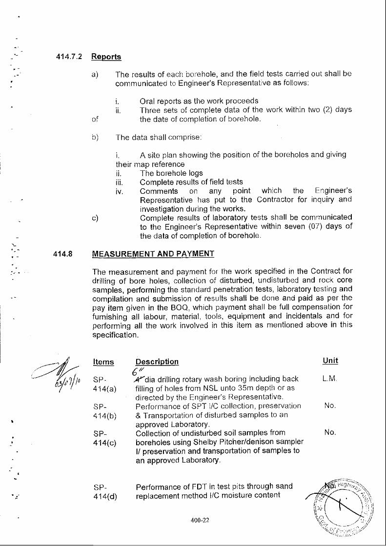
414.7.2 Reborts
a) The results of each borehole, and the field tests carried out shall becommunicated to Engineer's Representatlve as foljows:
i. Oral repods as the work Proceedsii. Three seis of complete data of the work within two (2) days
of the date of completion of borehole.
b) lhe dara shal l .onpr ise:
i. A site plan showing the position of the bofeholes and givingtheir map referenceii. The borehole logsiii. Complete results of field testsiv. Comments on any point which the Engineer's
Representative has put lo the Contractor for inquiry andinvestigation dufing the works.
c) Complete results of laboratory tests shall be communicatedto the Engineefs Representative within seven (07) days ofthe data of completion of borehole.
414.8 MEASUREMENT AND PAYMENT
The measurement and payment for the work specified in the Contract fordril l ing of bore holes, colleciion of disturbed, undisturbed and rock coresamples, performing the standard penetration tests, laboratory testing andcompilation and submission of results shall be done and paid as per thepay item given in the BOQ, which payment shall be full compensation forfurnishing all labour, material, tools, equipment and incidentals and forpefforming all the work involved in this item as mentioned above in thisspecification.
Items
SP,414(a)
SP.414(b)
SP-414(c)
SP-414(d)
Description6"lr 'dia dril l inq rotary wash boring including backfil l ing of holes from NSL unto 35m depth of asdirected by ihe Engineer's Representatlve.Performance of SPT l/C collection, preservation& Transportation of disturbed samples to anapproved Laboratory.Collection of undisturbed soil samples fromboreholes using Shelby Pitcher/denison samplerl/ preservation and transportation of samples toan approved Laboratory.
Performance of FDT in test plts through sandreplacement method l/C moisture content
Uni t
L .M.
N O .
No.
400-22
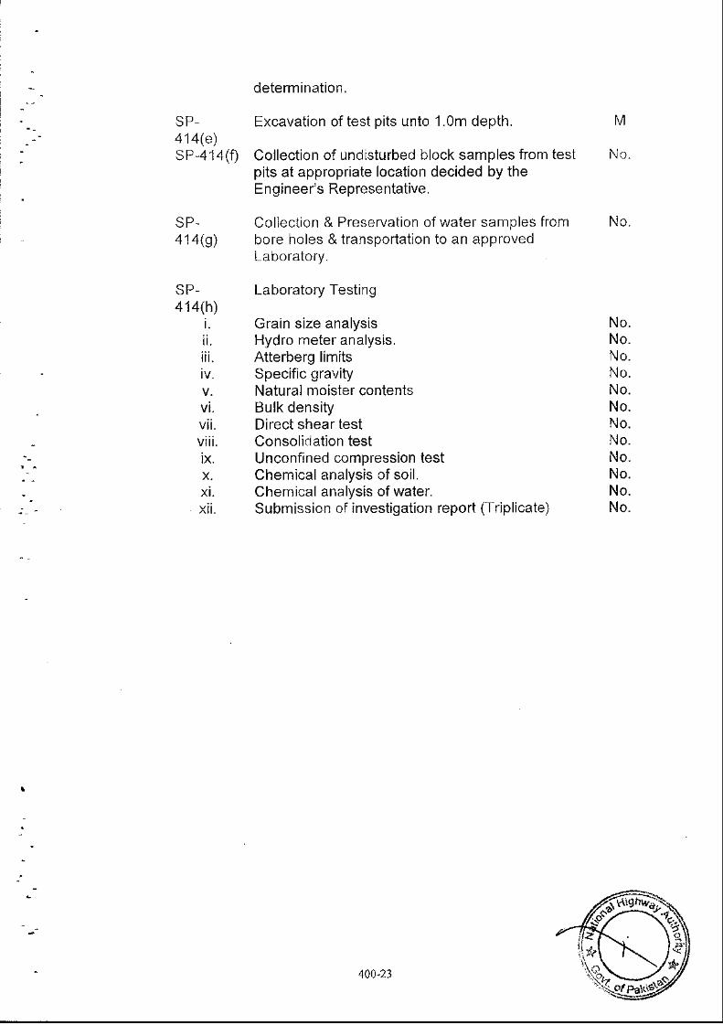
414(e)s P,414 (f)
a1a@)
determination.
Excavation of test pits unio 1.0m depth.
Collection of undisturbed block samples from testpits at appropriate location decided by theEngineer's Representative.
Colleclion & Preservation of watef samples frombore holes & transportatlon to an approvedLaDOratory.
Laboratory Testing
Grain size analysisHydro meter analysis.Atterberg limitsSpecific gravityNatural moister contentsBulk densityDirect shear testConsolidation testUnconfined compression testchemical analysis of soil.Chemical analysis of water.Submission of investigation report (Triplicate)
t\,1
No.
No.
No.No.No.No.No.No.No.No.No.No.No.No.
400-23
SP-415: MANUFACTURED TRADE MARK EXPANSION JOINTS
415.1 GENERAL
Expansion joints will follow Specifications of AASHTO-SS-D jvision ||-section 19 "Bridge deck joints seals"
The Contractor shall submit to the Engineer's Repfeseniative, completedocumentations about the Expansion joints he intends to use for themoven.rents shown on the Drawings, including references of the last 10years, material Specifications for metal, rubber and bonding betweenthem, fixations, and test certificates from authorized laboratories showingthat the proposed joints meet the specifications.
1. lt shall withstand traffic loads of the highway, and accommodatemovements between the deck and abutment or the adjacent deck.
2. lt shall have good riding quality and shall not cause anyinconvenience to road user.
3. lt shall not cause skidding hazard.4. lt shall not generate excessive noise or vibration dufing the
Passage of vehicles.5. Parts liable to wear out shall be easily replaceable.6. lt shall be watertight and will have provision for carrying away water
and silt.7. lt shall be easy to inspect and maintain.8. lt shall be resistant in hot and verv sunnv climate.
415.2 CONSTRUCTION REOUIREMENTS
The methodology of placing the expansion joint wil l be cleafly describedby the Contractof with a complete set of drawings.
Connection or overlapping between roaclway and walkway expanslonjolnts wil l be clearly shown.
Connection with water proofing of the deck wil l be detailed.
All necessary provisions in deck reinforcement wil l be indicated.
Elsewhere the submittal0.50m, with its fixations.
The expansion joints shall
will be accompanied by samples of at least
satisfy the following functional requlrements:
justified.will be Class Y
Initial gap at the time of placing will be clearly indicated andThe second stage reinforced concrete for fixations, if any,concrete and will be included in pay jtems SP a to d.
lij
4A0:24
.11 5,3 MEASSBEME!.IAND.EATENf
Measurement
The length of computed joints for foadwaybetween the faces of the kerbs, plus 150ra i l ing.
is measured in linear metremm height on each bridge
4 '15.3.2 Pavment
]-he accepted quantity measured as provlded above shall be paid for atthe contract unii price respectively for the pay items listed below andshown in the Bill of Quantities which price and payment shall be fullcompensation for furnishing all materials, labour, equipment, tools andincidentals and any work pertaining to expansion joints and which is notpaid for separately, necessary to complele the ltem.
PaymentItem No.
Descripiion Unit ofMeasurement
SP 415 Manufactured trade markJoints for roadway, for 25
expansionmm movement
M
ta0-25


![IN THE PESHAWAR HIGH COURT, PESHAWAR. · 2018-12-06 · 1 IN THE PESHAWAR HIGH COURT, PESHAWAR. [Judicial Department]. Regular First Appeal No.562-P/2014 Qazi Badr-ul-Wahab and others,](https://img.pdfslide.us/doc/110x75/5e42947ca5a2cd306d1bdfb3/in-the-peshawar-high-court-2018-12-06-1-in-the-peshawar-high-court-peshawar.jpg)