Embed Size (px)
Citation preview

Document #101-0086 1 07/18/08
Gold Line® ACW ParkingOperational Manual

Document #101-0086 2 07/18/08
TABLE OF CONTENTSI. INTRODUCTION .................................................................................................... 7II. INSTALLATION ..................................................................................................... 8
MECHANICAL INSTALLATION................................................................................................. 8Figure 2-1 Mounting Details ........................................................................................... 10ELECTRICAL INSTALLATION ................................................................................................. 11Figure 2-2 Relay Panel .................................................................................................. 13
III. OPERATION ....................................................................................................... 14NORMAL OPERATION .............................................................................................................. 14AUXILLARY STATUS RELAYS .................................................................................................. 14DISTRIBUTION PANEL ............................................................................................................. 15Figure 3-1 Distribution Panel ......................................................................................... 16Figure 3-2 Left Side View................................................................................................ 17Figure 3-3 Rear View ...................................................................................................... 17ENVIRONMENTAL CONTROLLER ........................................................................................ 17
IV. AUDITS .................................................................................................................. 18Inventory and Total Deposits ....................................................................................................... 18Inventory and Total Vending ........................................................................................................ 18Inventory and Total Overpaid ...................................................................................................... 18Audit and Total Vault Count ........................................................................................................ 19Clear Resettable Inventories ........................................................................................................ 19
CONFIGURATION REPORT ..................................................................................................... 19Event .......................................................................................................................................... 19Programed Proceed Prompts ...................................................................................................... 19Custom Proceed Prompts ........................................................................................................... 19Programed Welcome Prompts .................................................................................................... 19Custom Welcome Prompts.......................................................................................................... 20Programmed Closed Prompts ..................................................................................................... 20Custom Closed Prompts ............................................................................................................. 20Custom External Display Message .............................................................................................. 20
AUDIT REPORT ........................................................................................................................... 20Event .......................................................................................................................................... 20Cashier Data Sales-Resettable .................................................................................................... 20Cashier Data Sales-Perpetual ...................................................................................................... 20Transaction Summary .................................................................................................................. 20Reconciliation Of Current Cash ................................................................................................... 20
V. PROGRAMMABLE OPTIONS.......................................................................... 21Token Coin Mode ...................................................................................................................... 21Token Coin Value ....................................................................................................................... 21Tokenote® Mode ....................................................................................................................... 21Tokenote® Value ........................................................................................................................ 21Coupon Values ............................................................................................................................ 21

Document #101-0086 3 07/18/08
Set Fee Mode............................................................................................................................. 22Set Fees ..................................................................................................................................... 22Set Lost Ticket Fee ..................................................................................................................... 22Proceed Prompts ........................................................................................................................ 23Welcome Prompts ...................................................................................................................... 23Closed Prompts .......................................................................................................................... 23Ext Display Messages ................................................................................................................. 24Set Date & Time ......................................................................................................................... 24Set Empty Mode......................................................................................................................... 24Set Hopper Contents .................................................................................................................. 25Set Pay Default ........................................................................................................................... 25Set Refund Enable ...................................................................................................................... 25Receipt Headers ......................................................................................................................... 25Set Receipt Mode ....................................................................................................................... 25Set Printer Model ....................................................................................................................... 25Set Unit Number ......................................................................................................................... 25Set Welcome Delay .................................................................................................................... 25Vend Duration ............................................................................................................................. 25Set Proceed Time ....................................................................................................................... 26Time Event Status ....................................................................................................................... 26
VI. PROGRAMMING ............................................................................................... 27INVENTORY DEPOSITS? ....................................................................................................... 28INVENTORY VENDING? ....................................................................................................... 28INVENTORY OVERPAID? ...................................................................................................... 28AUDIT VAULT COUNT? ......................................................................................................... 29Clearing Inventories (GL-ACW-P) ............................................................................................. 29Clearing Inventories (GL-ACW-P with Ether Controller)............................................................. 30PRINT AUDIT REPORT? ......................................................................................................... 31PRINT CONFIGURATION REPORT? .................................................................................... 31SET ITEM PASSWORDS? ....................................................................................................... 32TOKEN COIN MODE?............................................................................................................ 32TOKEN COIN VALUE? ........................................................................................................... 32TOKENOTE MODE? ............................................................................................................... 33TOKENOTE VALUE? .............................................................................................................. 33COUPON VALUES? ................................................................................................................ 33SET FEE MODE? ...................................................................................................................... 33SET FEES? ................................................................................................................................ 34SET LOST TICKET FEE? ........................................................................................................ 35PROCEED PROMPTS? ............................................................................................................ 35WELCOME PROMPTS? .......................................................................................................... 35CLOSED PROMPTS ................................................................................................................ 36EXT DISPLAY MSGS? ............................................................................................................. 37SET DATE & TIME? ................................................................................................................. 37SET EMPTY MODE?................................................................................................................ 38SET HOPPER CONTENTS? .................................................................................................... 38SET PAY DEFAULT? ................................................................................................................ 38

Document #101-0086 4 07/18/08
SET REFUND ENABLE? ......................................................................................................... 39RECEIPT HEADERS?............................................................................................................... 39SET RECEIPT MODE? ............................................................................................................. 39SET PRINTER MODEL? .......................................................................................................... 40SET UNIT NUMBER? .............................................................................................................. 40SET WELCOME DELAY? ....................................................................................................... 40VEND DURATION? ................................................................................................................. 40SET PROCEED TIME? ............................................................................................................. 40TOTAL DEPOSITS? ................................................................................................................. 41TOTAL VENDING? .................................................................................................................. 41TOTAL OVERPAID? ................................................................................................................ 41TOTAL VAULT COUNT? ......................................................................................................... 42
VII. MAINTENANCE ............................................................................................... 43MONTHLY MAINTENANCE ..................................................................................................... 43
Hopper ....................................................................................................................................... 43Validator ..................................................................................................................................... 43Stacker ....................................................................................................................................... 43
ANNUAL MAINTENANCE ........................................................................................................ 43Hamilton Validators ..................................................................................................................... 43Hamilton Stackers ....................................................................................................................... 43
VIII. ERROR CODES ............................................................................................... 44ERROR CODES............................................................................................................................ 44
$5 Input Stuck ............................................................................................................................ 44$1 Input Stuck ............................................................................................................................ 4425¢ Input Stuck .......................................................................................................................... 45Token Input Stuck ...................................................................................................................... 45Drop Switch Stuck ..................................................................................................................... 45Unexpected Coin Drop ............................................................................................................... 45Hopper Coasting Error ............................................................................................................... 45Hopper Time-out ........................................................................................................................ 45Stacker Time-out ........................................................................................................................ 45Multiple Power Int ...................................................................................................................... 45Memory Data Altered! ................................................................................................................ 45Hopper Empty ............................................................................................................................ 46Release Button ............................................................................................................................ 46
IX. TROUBLESHOOTING ...................................................................................... 47Money Acceptance ................................................................................................... 47Money Acceptance (Continued) .............................................................................. 48Money Acceptance (Continued) .............................................................................. 49Hopper...................................................................................................................... 50Display ...................................................................................................................... 51
X. PARTS ..................................................................................................................... 52Interchanging Validators ............................................................................................................... 53
XI. OPTIONAL RECEIPT PRINTER ................................................................... 54

Document #101-0086 5 07/18/08
APPENDICES
Safety Precautions ......................................................................................................................... 54Inserting Paper ............................................................................................................................... 54
Loading Paper ............................................................................................................................ 54Figure 11-5 ..................................................................................................................... 55Clearing a Paper Jam in the Autocutter ....................................................................................... 55Head Cleaning Precautions and Procedure .................................................................................. 56
Cleaning Precautions ................................................................................................................... 56Cleaning Procedure: .................................................................................................................... 56
Figure 11-7 ..................................................................................................................... 56THERMAL PAPER SPECIFICATIONS ..................................................................................... 57
XII. EIC COMMUNICATION PANEL .................................................................. 58Figure 12-1 EIC Left Side View ...................................................................................... 58Figure 12-2 EIC Front View ............................................................................................ 59
XIII. TOKENOTES® ................................................................................................ 60Programming One or More Tokenotes® with the Same Value ..................................................... 60Programming Two Or More Tokenotes® With Different Values .................................................. 62
Voiding Tokenotes® ................................................................................................................... 65Appendix A .............................................................................................................. 70Default Settings......................................................................................................... 70Appendix B .............................................................................................................. 71Welcome Messages .................................................................................................. 71Appendix C .............................................................................................................. 71Proceed Prompts...................................................................................................... 71Appendix D .............................................................................................................. 71Closed Prompts ....................................................................................................... 71

Document #101-0086 6 07/18/08
ABOUT THIS MANUAL
PLEASE READ THIS MANUAL CAREFULLY PRIORTO INSTALLING THIS UNIT. A complete
understanding of the operation of this unit isessential for a successful installation.Refer to the Table of Contents for easy
navigation through this manual.This manual was designed to introduce the Gold Line® Parking Autocashier and to provide generalinformation about operation, installation and maintenance. This manual will enable the operator toprogram the GL-ACW-P, perform audits, detect error codes and perform basic troubleshooting proce-dures. Also included are pre-programmed factory settings, Item Names and Welcome Messages, aswell as a Tokenote® Training Guide for use with the optional Tokenotes®. Basic information is pro-vided for the hopper, stacker and validator. However, if additional information is needed for thesecomponents, refer to the appropriate manual. To obtain assistance from the manufacturer, please call(800) 837-5561 or (419) 867-4858. Or contact Hamilton Mfg. online @ http:\\www.hamiltonmfg.com.
When calling for assistance, it is important to have serial numbers readily available. Please recordthese numbers in the spaces provided.
GL-ACW-P MODEL & SERIAL #
CONTROLLER MODEL & SERIAL #
HOPPER MODEL & SERIAL #
STACKER MODEL & SERIAL #
VALIDATOR MODEL & SERIAL #
LOCK/KEY #
EIC SERIAL # (OPTIONAL)
Please complete the warranty card, which was included with your machine, and return it to the manu-facturer.

Document #101-0086 7 07/18/08
I. INTRODUCTIONThe many benefits offered by the GL-ACW-P automated car wash system include:♦ Reduced personnel, and thus lower payroll.♦ Increased security by eliminating the “silent partner” employee theft problem.♦ Increased operating time as a result of a tireless customer interface that is capable of
working 24 hours per day.
The following is a list of features for the GL-ACW-P:♦ A large, bright character display that welcomes customers and guides them through
their transactions.♦ It allows customers to pay for one of nine possible parking programs, returning
change if necessary.♦ The GL-ACW-P is capable of accepting Hamilton Tokenotes®. Tokenotes® are paper
tokens that are inserted into the Hamilton HVX, XE or STA Validator like dollar billsand used as credit towards the desired parking selection.
♦ Voice prompts to walk customers through the transaction process.♦ An Out of Service Relay used to signal an auto-dialing modem to contact the owner if
the unit shuts down. (Only the signaling relay is provided. The auto-dialer is notincluded.)
♦ An environmental control unit to help protect against the elements.♦ Newly designed Relay Panel that includes a Ground Fault Circuit Interrupter.♦ Universal harnessing and door for ease of adding options.
The following optional equipment is available for use with the GL-ACW-P:♦ An External Display featuring a 3" x 18" display area. The External Display is used
to display customized messages and to guide customers through transactions bydisplaying instructions in a large, bold fashion.
♦ Preformed bases that place the GL-ACW-P at the factory recommended height forvarious mounting situations.
♦ A Lighted Hood, which is recommended if the ACW is mounted on a base.♦ A hand-held printer used to receive a hard copy of all the audit information collected
by the GL-ACW-P.♦ A receipt printer to offer customers a hard copy of their transaction. This can also be
used to print an audit or configuration report.♦ A credit card acceptance system that gives the capability of accepting all major credit
cards.♦ A variety of bill acceptors. Choose from the Hamilton STA or XE or a Coinco® or
Mars® Validator. Tokenote® acceptance is available in the Hamilton STA or XEValidators only.
Document #101-0086 8 07/18/08
II. INSTALLATIONNOTE: It is very important to read and understand all of these instructions beforeattempting installation. Hamilton will not be responsible for injury dueto improper installation.
The installation process contains two distinct operations, Mechanical Installation, and ElectricalInstallation
MECHANICAL INSTALLATIONUnpacking
There are a number of points to keep in mind while unpacking your GL-ACW-P. These items will makethe installation and continued operation of your machine run smoother. These tips are listed below.
Be sure to save your keysThe keys and lock inserts are placed inside a small cloth bag, then packaged in a cushioned envelopeand attached to the outside of the machine. When removing the shrink-wrap, be sure to locate the bagcontaining the keys and set it aside so it does not get thrown away. MAKE A PERMANENT RECORDOF THE NUMBERS ON YOUR KEYS IN CASE A KEY IS LOST AND MUST BE REORDERED.
Remove the packing strap from the hopperThe hopper comes shipped with a packing strap secured around it to minimize the vibrations caused byshipping. If this strap is not removed, the hopper will not tip out for easy filling. The strap may be cutoff with a pair of wire cutters or sturdy scissors. Cardboard is placed around the edges of the hopper toprotect it during shipping. After removing the strap, be sure to remove the cardboard as well.
Remove all packing debris from the hopperDuring unpacking, ensure that debris does not fall into the hopper bowl. If this material is not removed,the hopper could jam. With the power completely disconnected, remove all loose material inside thehopper bowl.
Fill hopper with coinsBefore powering up the machine for the first time, it is recommended that the hopper be filled withcoins. In order for the hopper to dispense coins, there must be enough coins in the hopper bowl to touchthe two sensing plates located at the bottom of the bowl. Otherwise, the hopper will register as empty.
PositioningThere are no set guidelines for the placement of the GL-ACW-P. However, it is recommended that themachine is positioned far enough away from the wash entrance to minimize the amount of overspraythat may get into the GL-ACW-P. Also, there is a typical height, from the pavement to the bottom of thecabinet, of approximately 26".
Document #101-0086 9 07/18/08
MountingIt is recommended that the GL-ACW-P be mounted in a permanent enclosure. Safety is a primaryconcern, so the equipment must be securely mounted. Hamilton recommends using one of the follow-ing methods:
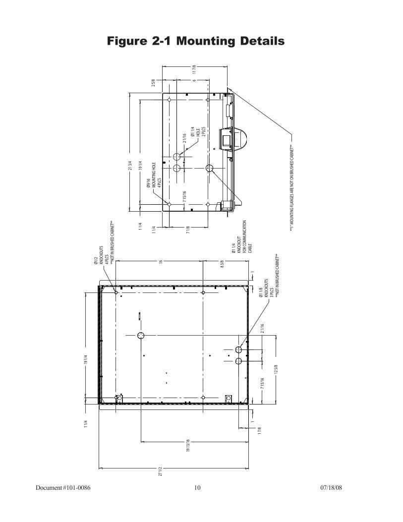
• The first method is to construct a small brick or concrete kiosk that will house theAutocashier. Figure 2-1 gives the GL-ACW-P mounting hole locations. Have your engineeror contractor recommend construction suitable for strength and stability.
• The other method involves mounting the GL-ACW-P on an optional ACW Base described inthe INTRODUCTION section. In this situation, the base is secured to the pavement and theGL-ACW-P is secured to the base. Fasteners to be used should be recommended by yourengineer as to strength and suitability. If this method is chosen, it is strongly recommendedthat the optional ACW Lighted Hood be installed. This addition serves to better insulate theGL-ACW-P from harsh environmental conditions as well as offering an attractive lighted top.Contact Hamilton Mfg. for installation instructions for the ACW Lighted Hood.
Running ConduitTypical electrical code requires low and high voltage wiring to be run in separate conduits. Because ofthis, the GL-ACW-P has one ½" conduit holes in the bottom of the cabinet. These bottom holes arematched with identical holes in any of the optional ACW Bases offered by Hamilton Mfg.
NOTE: At least one bottom hole must remain unused at all times.
• Conduit carrying high voltage 120VAC power lines, as well as any signal lines containing120VAC, should be connected to the bottom left conduit hole, as viewed from the front of themachine.
• Conduit carrying lines with 24VAC, 24VDC, 12VAC or 12VDC signals should be connectedto the bottom right conduit hole, as viewed from the front of the machine.
• If any external communication lines (telephone, POS etc.) are used, they should be runthrough seperate conduit.
Document #101-0086 10 07/18/08
Figure 2-1 Mounting Details
12 5
/8
6
Ø1 1
/4KN
OCKO
UTFO
R CO
MM
UNIC
ATIO
N CA
BLE
27 1
/2
11
19 1
3/16
19 1
/41
1/4
16
8 3/
8
1 7/
8
1 1/
419
1/4
21 3
/4
7 15
/16
2 1/
16
1 1/
4
7 1/
8
11 7
/8
2 5/
8Ø9
/16
MOU
NTIN
G HO
LE4
PLCS
Ø1 1
/4HO
LE2
PLCS
2 1/
167
15/1
6Ø1
1/8
KNOC
KOUT
S3
PLCS
**
NOT I
N BR
USHE
D CA
BINE
T**
Ø1/2
KNOC
KOUT
S 4
PLCS
**
NOT I
N BR
USHE
D CA
BINE
T**
**1"
MOU
NTIN
G FL
ANGE
S ARE
NOT
ON
BRUS
HED
CABI
NET*
*

Document #101-0086 11 07/18/08
ELECTRICAL INSTALLATIONCAUTION! TO AVOID SEVER INJURY OR DEATH, ALWAYS DISCON-NECT POWER TO THE MACHINE WHEN SERVICING!
This Autocashier operates on 120 VAC, 60 Hz. This unit uses a 5 AMP Circuit Breaker. This unit needsto be hard-wired with conduit. A Ground Fault Interrupter is included with the GL-ACW-P.
Pulling WiresThe number of wires needed to be pulled for the GL-ACW-P system is shown below:
For proper operation of the GL-ACW-P, all wires listed above must be pulled and terminated as ex-plained in the following section.
Wire TerminationsThe wire terminations should proceed as follows:
• One side of the three power supply wires (120VAC HOT, 120VAC NEU, and 120VAC GND)should be attached directly to the electrical service panel supplying power to the installation.They should be connected to a 15 AMP circuit breaker and the GL-ACW-P should be theonly device on this circuit. The other end of these three wires should be routed into the GL-ACW-P through the installed conduit. The wires should be terminated as follows:
••••• L1 (HOT) to terminal C1••••• L2 (NEU) to terminal C2••••• G (GROUND) to terminal C3.
• The ITEM 1 wire pair (ITEM 1 SIGNAL and ITEM 1 RETURN) is used to signal the park-ing controller that a customer has completed a transaction and is ready to enter lot. Thesignal presented to the car wash controller is a normally open, dry contact relay closure. Inthe GL-ACW-P, connect one end of this pair to terminals A1 and A2 on the Relay Panelterminal block. Refer to your parking controller literature for proper connections on the otherend of this pair.
• The CYCLE/INHIBIT pair is used for the parking controller to signal the GL-ACW-P whenthe ACW should be out of service. The signal coming from the parking controller must beable to energize the coil of a relay on the Relay Panel. This means that the parking controlleris supplying both voltage and current when it energizes the coil. Inside the ACW, the wiringconnections depend on the signal provided by the parking controller. The CYCLE/INHIBITpair should be connected directly to the terminal block of the Relay Panel. The proper con-nection will have one wire of this pair connected to terminal C5 of the Relay Panel (it doesn’tmatter which one) and the other wire of the pair connected to terminal C6.
Three Wires Electrical Power (Hot, Neutral and Ground)Two Wires For GateTwo Wires Cycle InhibitSpare Wires For Future Options
Document #101-0086 12 07/18/08
• The OUT-OF-SERVICE RELAY is included in the GL-ACW-P. Terminals B3 (normallyopen), B4 (common) and B5 (normally closed) are supplied as well. If an error occurs thatcauses the GL-ACW-P to go out of service, the relay will be activated.
Additional Wire Terminations For Use With The CreditCard System
The installation of the machine should proceed as outlined in the above section. However, if a CreditCard System is being used, the following must be performed, as well.
• The telephone line used for the ACW must be a dedicated line. Noother telephones or equipment can be connected with the same line.(The use of line splitters is not permitted.) If more than one machineis to be installed at the same location, a dedicated phone line must berun to each machine.
• The telephone line should be run in a separate conduit. If any otherwiring is run in the same conduit, communication problems couldoccur.
Setting Cycle Synchronization SwitchThe Cycle Synchronization Switch is the silver toggle switch located on the Relay Panel. If an externalsignal is being used to inhibit the operation of the GL-ACW-P this switch determines how the Cycle/Inhibit relay should operate. In the (A) active mode external power must be supplied to the coil of therelay during normal operation then removed to inhibit the GL-ACW-P. In the (P) passive mode noexternal power is supplied to the coil of the relay during normal operation. The coil would be energizedto inhibit the GL-ACW-P. When not using an external inhibit signal this switch should be set to the (P)passive mode.
General TestAfter completing all of the steps under Mechanical and Electrical Installation, be sure to test thefollowing items for proper function.
• Turn on power at the Relay Panel.• Be sure to test all facets of the operation, including the bill acceptor
and coin acceptors.• Test for proper actuation of gate and Cycle/Inhibit control.• Ensure that coins are being dispensed for both change and as a refund.
If there are any problems refer to the TROUBLESHOOTING sectionor contact Hamilton Mfg.

Document #101-0086 13 07/18/08
Figure 2-2 Relay Panel
A
B
C
1 2 3 4 5 6
1 2 3 4 5 6
L1 L2 G 4 5 6
P A1
2
3
4
ON
OFF

Document #101-0086 14 07/18/08
III. OPERATION
NORMAL OPERATIONWhen a customer drives up to the Autocashier, they are greeted by a bright display that welcomes and/or instructs them on how to proceed.
When operating in the FEE ON ENTRY or FEE ON EXIT mode a flat fee is charged depending onwhich time zone is active. The customer is prompted to deposit that amount. Once the customer hasdeposited enough credit in money, tokens, credit or Tokenotes to pay the parking fee, the transactionis complete. At this point, the GL-ACW-P will:
• Return any necessary change.• Activate the gate.• Signal the driver to proceed by displaying the Proceed Messages.• After several seconds of displaying the message, the display will return to the se-
quencing Welcome Messages and the system prepares for the next transaction.
When operating in the FEE BY TIME mode a customer exiting the lot is first prompted to enter thecode from the ticket issued at the point of entry. The Hamilton Time Pass system then calculates theelapsed time and computes the fee. Next, the customer is prompted to deposit that amount. Oncethe customer has deposited enough credit in money, tokens, credit or Tokenotes to pay the parkingfee, the transaction is complete. At this point, the GL-ACW-P will:
• Return any necessary change.• Activate the gate.• Signal the driver to proceed by displaying the Proceed Messages.• After several seconds of displaying the message, the display will return to the se-
quencing Welcome Messages and the system prepares for the next transaction.
AUXILLARY STATUS RELAYSThere are four relays located on the left side of the Relay Panel numbered 1 – 4 (see Figure 2-2).Relay 1 fires momentarily when the GL-ACW-P has completed the transaction to signal the gate toopen. The normally open contacts for Relay 1 are at terminals A1 and A2 on the Relay Panel. Theremaining three relays provide some optional status signals as follows:
• Relay 2 goes active at the same time as relay 1, to open a gate. A typical application forRelay 2 would be to connect it to an external counter to keep track of the number of carsentering or exiting the lot. The normally open contacts for Relay 2 are at terminals A3 andA4 on the Relay Panel.
• Relay 3 goes active whenever events 1–8 are active and goes off when the base event 0 isactive. This signal is intended for use with the Hamilton Time Pass system in order to inhibitthe Ticket Dispenser from issuing a ticket when the Autocashier is in one of the higher

Document #101-0086 15 07/18/08
priority flat rate events. The normally open contacts for Relay 3 are at terminals A5 and A6on the Relay Panel.
• Relay 4 goes active whenever an active event is programmed as closed. An application forthis signal would be to inhibit the entry gate when the GL-ACW-P is at a time when it isprogrammed to have the parking lot closed. The normally open contacts for Relay 4 are atterminals B1 and B2 on the Relay Panel.
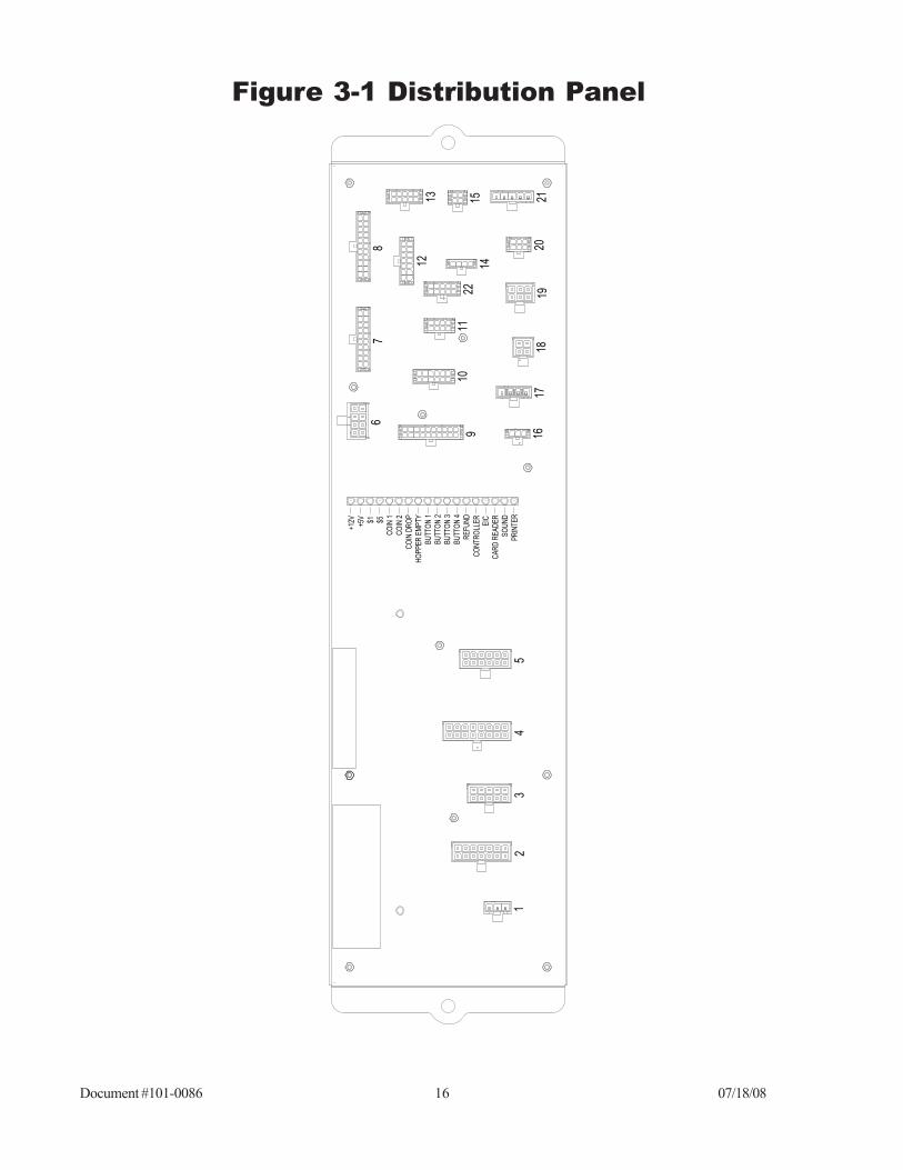
DISTRIBUTION PANELThe Distribution Panel is the distribution point for connections to individual components. When re-moving harnesses from the Distribution Panel, you must first squeeze the release tabs on the connec-tors. The harnesses are connected as follows:
1 DC Power Supply Input 12 Keypad2 ACW Controller AC1 13 Sound3 Hamilton Stacker/Validator 14 Credit Card4 Relay Pan 15 ACW Internal Display5 hopper/24V Transformer Input 16 POS N/A6 DC Power Supply Output 17 External Serial Interface7 ACW Controller DC1 18 External Display8 ACW Controller DC2 19 3rd Party Validator9 Printer 20 Coin Mechs10 EIC 21 24v Transformer Output11 YES, NO and REFUND Select Buttons 22 Wash Select Buttons Eight Function
A series of red LED’s on the Distribution Panel will help in the troubleshooting process. The followingis a list of their indications. See Figure 3-1 for a complete diagram of the Distribution Panel.
+12V Should always be on. If it is off, check AC power supplies and
fuses under Hopper as well as GFI.+5V Same as above.$1 Should flash when a $1 or a Tokenote is accepted.$5 Should flash when a $5, $10, $20 or Tokenote is accepted.
COIN 1 Will flash when a coin is accepted in Coin Mech #1.COIN 2 Will flash when a coin is accepted in Coin Mech #2.
COIN DROP Will flash each time a coin is paid out of the Hopper.HOPPER EMPTY Will be on steady when Hopper is empty.
BUTTON 1BUTTON 2BUTTON 3BUTTON 4REFUND
CONTROLLER Flashes as Controller communicates with EIC.EIC Flashes as Controller receives signal back from EIC.
CARD READER Will flash when card is swiped.SOUND Will flash when voice is operating.
PRINTER Will be on steady while report is printing from external printer.
Will flash when the selection buttons or the refund button is
pressed.
Document #101-0086 16 07/18/08
Figure 3-1 Distribution Panel
PR
INTE
RS
OU
ND
CA
RD
RE
AD
ER
EIC
CO
NTR
OLL
ER
RE
FUN
DB
UTT
ON
4B
UTT
ON
3B
UTT
ON
2B
UTT
ON
1H
OP
PE
R E
MP
TYC
OIN
DR
OP
CO
IN 2
CO
IN 1$5$1+5V
+12V
22
2120
1918
1716
1514
1312
1110
9
87
6
54
32
1

Document #101-0086 17 07/18/08
2 AMP FUSE
5 AMP FUSE
FAN
120V POWER
BOTH 24VTRANSFORMERS
THERMOSTAT
ENVIRONMENTAL CONTROLLERThe Environmental Controller is used to maintain temperature in the GL-ACW-P. It contains thetwo replaceable fuses, as well as the thermostat. See Figures 3-2 and 3-3 for illustrations of theirlocations.
2 Amp FuseThe 2 amp fuse is on the primary side of two 24VAC transformers that power the coin mechs,external display and 3rd party validators.
5 Amp FuseThe 5 amp fuse is for the fan and heater.
Figure 3-2 Left Side View
Figure 3-3 Rear View

Document #101-0086 18 07/18/08
IV. AUDITSFor added security, the GL-ACW-P contains two complete sets of audits.
The RESETTABLE audit categories include:• INVENTORY DEPOSITS?• INVENTORY VENDING?• INVENTORY OVERPAID?• AUDIT VAULT COUNT?
The NON-RESETTABLE audit categories include:• TOTAL DEPOSITS?• TOTAL VENDING?• TOTAL OVERPAID?• TOTAL VAULT COUNT?
The information stored is the same for both sets. However, the RESETTABLE AUDITS are valuesaccumulated since the last time the audits were cleared. The NON-RESETTABLE AUDITS containvalues accumulated throughout the entire life of the controller while it has been inside the GL-ACW-P.
For details on how to view the audit information on your GL-ACW-P, refer to the PROGRAMMINGsection. (It may be necessary to read the entire section to get a complete understanding of how thecontroller functions.)
The information stored in each audit is described below.
Inventory and Total DepositsThe DEPOSITS category shows a complete dollar amount of everything deposited into the machine,minus the change returned to the customer. It is broken down into three subcategories, CASH, TO-KENS and CARDS. The CASH deposit subcategory gives a total dollar amount of all $1, $5, $10, $20bills and quarters deposited. It takes into consideration change that has been returned to the customer,displaying the amount of profit made. The TOKEN deposit subcategory gives a total dollar amount ofall Tokenotes® and token coins deposited. The CARDS subcategory gives the total dollar amount ofall WashCard®, debit card and credit card transactions, if applicable.
Inventory and Total VendingThe VENDING category gives a complete breakdown of each parking use purchased and the methodof payment for each wash. It does this by showing the total amount of cash received in payment foreach of the parking options as well as the dollar amount of token credit and debit card credit received.The VENDING category also takes into consideration the amount of change that has been returned tothe customer, displaying the amount of profit made.
Inventory and Total OverpaidThe OVERPAID category totals the amount of change that could not be dispensed to customers. Mostfrequently, this category is adjusted when the coin hopper is empty and the GL-ACW-P is operating in

Document #101-0086 19 07/18/08
the USE EXACT AMOUNT mode. If a customer deposits more than the selected wash price, thedifference between the amount deposited and the selected wash price will be added to the overpaidcategories.
Audit and Total Vault CountThe VAULT COUNT category gives a complete breakdown of all deposits and cash payouts. It doesthis by offering specific counts on the number of each denomination bill that has been deposited, thenumber of each type of Tokenote® deposited, and the number of token coins, debit card approvals andquarters deposited. There is also a count of the number of quarters dispensed as change.
Clear Resettable InventoriesClearing the RESETTABLE INVENTORIES has the effect of zeroing out all values and counts thathave been accumulated since the last time these inventories were cleared. The categories affected areINVENTORY DEPOSITS, INVENTORY VENDING, INVENTORY OVERPAID, and AUDIT VAULTCOUNT. The NON-RESETTABLE categories remain unchanged. Refer to the PROGRAMMING sec-tion for details on how to clear the inventories.
CONFIGURATION REPORTAt the top of the Configuration Report the title of the report and the date will be displayed. Next thesettings for:
• Token Coin Mode• Token Coin Value• Tokenote Mode• Tokenote Value• Coupon #1 Value• Coupon #2 Value• Coupon #3 Value• Coupon #4 Value
The rest of the Configuration Report is divided into nine different categories.
EventThis category shows the prices set for the nine available events. (0-8)
Programed Proceed PromptsThe four available lines of the Proceed Prompts are displayed.
Custom Proceed PromptsThe eight Custom Proceed Prompts are displayed.
Programed Welcome PromptsThe four available lines of the Welcome Prompt are displayed.
Document #101-0086 20 07/18/08
Custom Welcome PromptsThe eight available lines of the Custom Welcome Prompts are displayed.
Programmed Closed PromptsThe four available lines of the Closed Prompt are displayed.
Custom Closed PromptsThe eight available lines of the Custom Closed Prompts are displayed.
Custom External Display MessageThe first and second half of the four available External Display Messages is displayed.
At the bottom of the report the settings for the following are displayed:• Empty Mode• Hopper Contents• Pay Default• Refund Button• Receipt Headers (1-8)• Receipt Mode• Printer Model• Unit Number• Fee Mode• Welcome Delay• Vend Duration• Proceed Time
AUDIT REPORTAt the top of the report, the date and time that the report was generated will be displayed, followed bythe settings for:
EventThe nine events (0-8) will be listed along with type, start, end and fee.
Cashier Data Sales-ResettableThe resettable inventory for cash, tokens and card.
Cashier Data Sales-PerpetualThe non erasable inventory for cash, tokens and card.
Transaction SummaryThe resettable and perpetual inventory of bills, coins, tokens, tokenotes, cards and the hopper coin outcount.
Reconciliation Of Current CashThis area will show currency deposited, coins deposited and dispensed, net coins and cashier balance.

Document #101-0086 21 07/18/08
V. PROGRAMMABLE OPTIONSThe GL-ACW-P has a number of programmable options that can be used by the parking lot owner to custom-ize the operation of the machine. These programmable options give the car wash owner the ability to:
♦ Set the desired prices♦ Program custom messages♦ Program the amount of credit given for token coins and/or Hamilton Tokenotes®
The following is a description of all of the programmable options, in the order they will be encounteredin the PROGRAMMING MODE. For information on how to program these options, refer to the PRO-GRAMMING section.
Token Coin ModeThere are two choices for the TOKEN COIN MODE, MULTIPLE CREDITS and SINGLE CREDIT.MULTIPLE CREDITS allows the customer to insert as many token coins as necessary to pay for theselected rate. The SINGLE CREDIT MODE, limits the customer to receiving credit for only one tokencoin per transaction. SINGLE CREDIT MODE is often used when token coins are distributed as apromotion to get customers to choose your lot for reduced parking rates. By only accepting one creditper customer, the customer will not be able to accumulate the promotional token coins and receive freeparking. In this mode, you will still be collecting some revenue on every car parked.
Token Coin ValueThis category is used to program the amount of credit given when a token coin is accepted by the GL-ACW-P. The value can be anything from $0.00 to $63.75 programmable in $0.25 increments.
Tokenote® ModeThere are two choices for the TOKENOTE® MODE, MULTIPLE CREDITS and SINGLE CREDITMODE. MULTIPLE CREDITS allows the customer to insert as many Tokenotes® as necessary to payfor tparking. The SINGLE CREDIT MODE, on the other hand, limits the customer to receiving creditfor only one Tokenote® per transaction. SINGLE CREDIT MODE is often used when Tokenotes® aredistributed as a promotion to get customers to choose your lot for reduced parking rates. By onlyaccepting one credit per customer, the customer will not be able to accumulate the promotionalTokenotes® and receive a free wash. In this mode, you will still be collecting some revenue on everycar parked.
Tokenote® ValueThis category is used to program the amount of credit given when the validator accepts a Tokenote®trained without a Training Coupon. The value can be anything from $0.00 to $63.75 programmable in$0.25 increments.
Coupon ValuesThis category is used to program the amount of credit given when a Tokenote, trained with one of fourTraining Coupons (Coupon #1 – 4), is accepted by the validator. Each coupon can have a separatevalue for each of the four washes that range from $0.00 to $63.75 programmable in $0.25 increments.
Document #101-0086 22 07/18/08
Set Fee ModeThis category is used to select how the parking fee is calculated and displayed to the customer. TheFEE ON ENTRY and FEE ON EXIT modes determine the charges based on the time zone and fees setin the SET FEES category. Both of these modes display a flat fee to the customer. The difference isthat the voice prompting has been tailored for a customer either entering the lot or exiting the lot. TheFEE BY TIME mode is used in conjunction with the Hamilton Time Pass system, which calculates thefee, based on the amount of time the customer has been parked. If this mode is selected the customeris first prompted to enter a code from the ticket received on entry. The GL-ACW-P then transmits thiscode to the Time Pass controller where the fee is calculated and returned for display to the customer.
Set FeesWhen operating in the FEE ON ENTRY or FEE ON EXIT mode, this category is used to program theprice for each of the nine parking selections available on the GL-ACW-P. The values can be anythingfrom $0.25 to $99.75 programmable in $.25 increments.The nine parking selections are numbered 0-8. The Base Fee or the Fee that will be charged the major-ity of time is set in position 0.Additional fees that will be charged for specific events or days will be entered in positions 1-8.You must keep in mind that when programming in positions 1-8 that position 1 will override position 0,position 2 will override position 0 & 1, position 3 will override position 0, 1 & 2 and so on. The largerposition number will always override a lower position number.Example:• If you wish to have three different pricing levels programmed at your lot ($5 for daytime
Monday – Friday 6AM- 5:30PM, $2 for night time Monday – Friday 5:30PM – 6AM and$10 weekends 6AM Saturday – 6AM Monday).
• The Monday – Friday 6AM-5:30PM would be the Base Fee programmed in position 0.
• The night fee (Monday – Friday 5:30PM – 6AM) would be programmed in position 1.
• Finally place the weekend fee in position 2.
NOTE: Always keep in mind that the larger position number will alwaysoverride a lower position number.
Set Lost Ticket FeeThis category is used when operating in the FEE BY TIME mode as part of the Hamilton Time Passsystem. It allows an operator to set a fixed fee that will be charged whenever a customer enters thelost ticket code of *1234. With appropriate signage at the lot, this fixed code can be used by a cus-tomer that may have lost the ticket that was issued to them when they entered the parking lot. Usu-ally the Lost Ticket Fee would be set to the highest amount likely to be charged for parking in thelot. This eliminates any incentive for a customer to use the lost ticket code instead of the code on theticket he was issued; while still providing a method for someone that has truly lost their ticket tomake payment and exit the lot. The Lost Ticket Fee can be set to any value from $0.25 to $99.75programmable in $0.25 increments. If you do not want to use this feature it can also be set to DIS-ABLED which causes the *1234 code to be ignored.

Document #101-0086 23 07/18/08
Proceed PromptsThis category is used to select the sequencing messages that are seen after a customer pays for parkingand is waiting to proceed into the wash. There are up to four sequencing Proceed Prompts possible.These four messages may be chosen from a list of pre-programmed messages or a custom message maybe created. Up to eight different custom messages can be programmed. If a ninth custom message isattempted, it overwrites the first custom message programmed. Once a custom message is programmed,it will be listed along with the pre-programmed messages when scrolling through the available mes-sage choices. These custom messages can be deselected or overwritten, but never erased. If you do notwish to use all four messages, simply program the desired messages with the pre-programmed orcustom messages and program the remaining messages with the “-NOT USED-” message located inthe pre-programmed message list. This message will not appear on the screen. When this message isencountered in the message sequence, it automatically skips to the next message in the sequence with-out any time delay.
Proceed Prompts Example: To guide a customer through a transaction, the follow-ing messages may be selected:
PROCEED MESSAGE #1 “THANK YOU”PROCEED MESSAGE #2 “PLEASE DRIVE AHEAD”PROCEED MESSAGE #3 “-NOT USED-”PROCEED MESSAGE #4 “-NOT USED-”
Welcome PromptsThis category is used to select the sequencing messages that are seen when a customer first pulls up tothe GL-ACW-P. There are up to four sequencing Welcome Messages possible. These four messagesmay be chosen from a list of pre-programmed messages or a custom message may be created. Up toeight different custom messages can be programmed. If a ninth custom message is attempted, it over-writes the first custom message programmed. Once a custom message is programmed, it will be listedalong with the pre-programmed messages when scrolling through the available message choices. Thesecustom messages can be deselected or overwritten, but never erased. If you do not wish to use all fourmessages, simply program the desired messages with the pre-programmed or custom messages andprogram the remaining messages with the “-NOT USED-” message located in the pre-programmedmessage list. This message will not appear on the screen. When this message is encountered in themessage sequence, it automatically skips to the next message in the sequence without any time delay.
Welcome Prompts Example: To guide a customer through a transaction, the follow-ing messages may be selected:
WELCOME MESSAGE #1 “TO ENTER LOT”WELCOME MESSAGE #2 “DEPOSIT”WELCOME MESSAGE #3 “-NOT USED-”WELCOME MESSAGE #4 “-NOT USED-”
Closed PromptsThis category is used to select the sequencing messages that are displayed when the GOLD LINEACW PARKING is signaled that the lot is full or it is programmed to be disabled. There are up to foursequencing messages possible. The four messages may be chosen from a list of pre-programmed mes-sages or a custom message may be created. Up to eight different custom messages can be programmed.

Document #101-0086 24 07/18/08
If a ninth custom message is attempted, it overwrites the first custom message programmed. Once a custommessage is programmed, it will be listed along with the pre-programmed messages when scrolling through theavailable message choices. These custom messages can be de-selected or overwritten, but never erased. If itis undesirable to sequence through all four messages, program the desired messages with pre-programmed orcustom messages and program the remaining messages with the “ — NOT USED —” message located in thepre-programmed message list. This message will not appear on the screen. When this message is encounteredin the message sequence, it will automatically skip to the next message in the sequence without any time delay.As a programming example, to tell a customer that the lot is full and to try again some other time, the ClosedMessages may be programmed as follows:
Closed Prompts Example: To guide a customer through a transaction, thefollowing messages may be selected:
CLOSED MESSAGE #1 “PARKING LOT FULL”CLOSED MESSAGE #2 “PLEASE COME AGAIN”CLOSED MESSAGE #3 “—NOT USED—”CLOSED MESSAGE #4 “—NOT USED—”
Ext Display MessagesThis category is used to program up to four personalized External Display messages. The messagesdisplayed are divided into two halves.
Set Date & TimeThis category is used to program the current day, date and time. The time is programmed similar to thefollowing example:
WED_05-30-01_05:30_P
The day is selected followed by the month, date, and year, then the hour and minute, and finally theAM/PM specification.
Set Empty ModeThis category is used to program how the GL-ACW-P will respond when the hopper runs out of coins.There are two choices, OUT OF SERVICE and USE EXACT AMOUNT. If OUT OF SERVICE isselected and the hopper goes empty, the display will stop showing the Welcome Messages and insteadshow the sequencing messages “OUT OF SERVICE” and “HOPPER EMPTY”. When this occurs, thebill acceptor and coin acceptors will be deactivated so no further transactions can occur until the hop-per is filled with coins. If USE EXACT AMOUNT is selected and the hopper goes empty, the billacceptor and coin acceptors will remain activated and the display will stop showing the WelcomeMessages and instead show the sequencing messages “USE EXACT AMOUNT” and “NO CHANGERETURNED”. In this mode, it is possible to continue performing transactions even though the hopperis empty since the customer is being notified that no change will be returned and the exact amount mustbe deposited.
Set Hopper Contents

Document #101-0086 25 07/18/08
This category is used to set the type of coin being dispensed from the hopper. It can be quarters, $1 coins or$2 coins.
Set Pay DefaultThis mode is used when a fault is detected in one of the payment devices, such as the validator or oneof the coin acceptors. There are two options to choose from in this mode, USE ALT PAYMENT orOUT OF SERVICE. If a fault has been detected and the default payment mode is set to OUT OFSERVICE, the ACW will shut itself down until the error has been corrected. However, if the defaultpayment mode is set to USE ALT PAYMENT, the ACW can continue operating, even if there is a faultin one or more of its payment devices. The display will give examples for payment methods that willbe accepted. If all payment options are determined to be faulty, the machine will shutdown, displayingan error message for the last device to have a problem.
Set Refund EnableThis category is used to enable or disable the refund button.
Receipt HeadersWhen using the optional receipt printer, this category allows up to 8 customized lines of text to beprinted on the top of every receipt printed.
Set Receipt ModeWhen using the optional printer, this category offers a choice of when a receipt will be printed. Youmay select from NEVER, ALWAYS, or ASK.
Set Printer ModelWhen an optional printer has been installed, this category selects which specific model of printer willbe supported.
Set Unit NumberAllows you to set the unit number for the ACW when it is connected to a Hamilton Time Pass network.Each ACW on the network must have a unique unit number.
Set Welcome DelayThis category is used to set the verbal welcome greeting to be delayed from 0 to 30 seconds. Thisallows a customer time to completely drive up to the ACW and open their window before the welcomegreeting begins speaking.
Vend DurationThis category is used to program the length of time that the GL-ACW-P turns on its vend relays. Thevend relays get turned on to signal the parking gate that the customer has finished the transaction andis ready to drive ahead. The length of time these relays should be held depends on the requirements ofthe particular parking gate being used. Refer to the parking gate manual before setting this category.The possible values range from 0.1 - 4.0 seconds.
Set Proceed Time

Document #101-0086 26 07/18/08
This category is used to program the length of time that the ACW prompts a customer to proceed into theparking lot after the customer has completed a transaction. The possible values range from 1 to 9.9 seconds.The PROCEED TIME must be longer or equal to the VEND DURATION. If the PROCEED TIMEis set for a shorter time, the value of the VEND DURATION will also be used as the PROCEEDTIME.
Time Event StatusThis category is a non-programming category. The category only displays the status of the event which isenabled. In addition, it displays the number of the event which is enabled.
Example: “Event #0 Enabled”

Document #101-0086 27 07/18/08
VI. PROGRAMMINGThe GL-ACW-P comes pre-programmed from the factory. However, you may decide to program the GL-ACW-P to meet your individual needs. DO NOT program a category that you do not fully understand!Refer to the Programmable Options section of this manual for a complete explanation of eachcategory’s function.
In order to program the GL-ACW-P, begin at the Welcome Prompt, then follow the stepsbelow:1. Open the machine, and locate the controller on the lower inside left
hand cabinet wall. Push the top and bottom buttons simultaneously forabout 3-5 seconds to enter the programming mode.
2. To begin programming, you must use the buttons located on the insideof the door above the display, numbered 1-4.• The #2 button is always used as a scroll button. The #4 button is always used
to enter a category. The #1 button is used to save options and exit that cat-egory. The refund button is used to exit the programming mode.
Note: After three minutes of inactivity in programming mode, the machine willautomatically return to “normal” mode to prevent from being accidentally leftin the programing mode after completion.
In order to program the GL-ACW Park with an Ether Controller, begin at the WelcomePrompt, then follow the steps below.
1. Open the machine and locate the controller on the lower inside left hand cabinet wall.2. Press and Release the “Program” button on the controller.3. The display should now show “Inventory Deposits”.4. To begin programming, you will use the four button keypad on top of the internal dis
play and the refund button button located on the door.• The Refund button is used to exit the programming mode.• The F1 function button is used to save options and exit the category.• The F2 function button is used to scroll up through the categories.• The F3 function button is used to scroll down through the categories.• The F4 function button is used to enter a category.
When in the programming mode use the F2 or F3 function buttons to scroll up and down through themenu choices. Once you have selected a category, use the F4 function button to enter into that category.If a change is needed, then use the F2 or F3 function buttons to make that change. Once the change ismade press the F1 function button to exit the category.
5. When all changes are complete and you are at the programming categories level (notinside of a category) Press the “Refund” button (located on the door) to return to Welcome message. Programming complete.
3. The categories and specific programming instructions begin below and are

Document #101-0086 28 07/18/08
The categories and specific programming instructions begin belowand are listed in order as the appear in the menu.
INVENTORY DEPOSITS?To view the current Inventory Deposits:
• Press the #4 button to enter the category.• Press the #4 button to scroll between the options:
CASH =TOKENS =CARDS =
• Press the #1 button to exit the category.• Press the #2 button to scroll to the next category.
INVENTORY VENDING?To view the current Inventory Vending:
• Press the #4 button to enter the category.• Press the #4 button to scroll between the options (Event 0-8):
EVENT 0 CNT (count)EVENT 0 CSH (cash)EVENT 0 TOK (token)EVENT 0 DEB (debit)
EVENT 1 CNTEVENT 1 CSHEVENT 1 TOKEVENT 1 DEBEVENT 2 CNTEVENT 2 CSHEVENT 2 TOKEVENT 2 DEBEVENT 3 CNTEVENT 3 CSHEVENT 3 TOKEVENT 3 DEBEVENT 4 CNTEVENT 4 CSHEVENT 4 TOKEVENT 4 DEB
(continues through EVENT 8)• Press the #1 button to exit the category.• Press the #2 button to scroll to the next category.
INVENTORY OVERPAID?To view the current Inventory Overpaid:
• Press the #4 button to enter the category.• The display will read:
OVERPAID $

Document #101-0086 29 07/18/08
• Press the #1 button to exit the category.• Press the #2 button to scroll to the next category.
AUDIT VAULT COUNT?To view the current Audit Vault Count:
• Press the #4 button to enter the category.• Press the #4 button to scroll between the options:
$20 BILL CNT$10 BILL CNT$5 BILL CNT$2 COIN CNT$1 BILL CNT$1 COIN CNT
QUARTER CNTTOKEN CNT
TOKENOTE CNTCOUPON 1 CNTCOUPON 2 CNTCOUPON 3 CNTCOUPON 4 CNT
CARD CNTHOPPER CNT
• Press the #1 button to exit the category.• Press the #2 button to scroll to the next category.
Clearing Inventories (GL-ACW-P)
Note: Clearing memory clears ALL resettable inventory categories at once.Resettable categories: Inventory Deposits, Inventory Vending, Inventory Overpaid, andAudit Vault Count
• Enter a resettable inventory category, such as INVENTORY DEPOSITS?, bypressing the #4 button.
• Press the #2 and #3 buttons simultaneously for about five seconds.• The display will show the sequencing messages:
ACTION TO CLEAROR RETURN TO ABORT
• Pressing the #4 button will now clear the memory, and the display will thenread:
MEMORY CLEARED!• Or to abort, press the #1 button. You will then be returned to the menu mode. • Press the #2 button to scroll to the next category, or press the #4 button to exit
the programming mode.

Document #101-0086 30 07/18/08
Clearing Inventories (GL-ACW-P with Ether Controller)
Clearing memory clears ALL resettable inventory categories at onceResettable categories: Inventory Deposits, Inventory Vending, Inventory Overpaid, andAudit Vault Count
Note: There are three different processes to clear the Inventories from an Ether Controller.
Process #1
In order to clear inventories at the GL-ACW Park with the Ether Controller, begin at the Welcome Prompt, then follow the steps below:
1. Open the machine and locate the controller on the lower inside left hand cabinet wall.2. Press and Hold the “Inventory” button on the controller for about 3 seconds.3. The display should now show “Clear Inventories?”, “Action to Clear”, “Or Return to
Abort”.• The F1 function button will be used to abort the inventory clear.• The F4 function button will be used to clear the inventories.
4. If you select to abort the inventory clear, press the F1 function button and the displaywill show “Memory Not Cleared”. Then in about 3 seconds you will return to the Welcome Prompt.
5. If you select to clear the inventories, press the F4 function button and the display willshow “Memory Cleared”. Then in about 3 seconds you will return to the WelcomePrompt.
Process #2
In order to clear the inventories at the GL-ACW Park with an Ether Controller, begin at theWelcome Prompt, then follow the steps below:
1. Open the machine and locate the controller on the lower inside left hand cabinet wall.2. Press and Release the “Program” button on the controller.3. The display should now show “Inventory Deposits”.4. To clear the Inventories, you will use the four button keypad on top of the internal dis
play and the refund button located on the door.• The Refund button is used to exit the programming mode.• The F1 function button is used to save options and exit the category.• The F2 function button is used to scroll up through the categories.• The F3 function button is used to scroll down through the categories.• The F4 function button is used to enter a category.
When in the programmming mode use the F2 or F3 function button to scroll up or down through themenu choices to select one of the four resettable inventory categories. Once you have selected thecategory, use the F4 function button to enter into that category. (Example Inventory Deposits selected)
Document #101-0086 31 07/18/08
5. To clear the inventories press and hold the F2 and F3 function buttons until displayshows “Clear Inventories?”.
6. If you select to abort the clearing of inventories, then press the F1 function button andthe display will show “Memory Not Cleared”. Then in about 3 seconds the display willshow “Inventory Deposits”.
7. If you select to clear the inventories, then press the F4 function button and the displaywill show “Memory Cleared”. Then in about 3 seconds the display will show “Inventory Deposits”.
8. Once the inventories have been cleared and you are at the programming categorieslevel, Press the “Refund” button to return to Welcome Prompt.
Process #3
In order to clear the inventories at the GL-ACW with an Ether Controller, begin at the WelconePrompt, then follow the steps below:
1. Open the machine and locate the controller on the lower inside left hand cabinet wall.2. Press and Hold the “Inventory” button on the controller for about 3 seconds.3. The display should now show “Clear Inventories?”, “Action to Clear”, “Or Return to
Abort”.• The” Inventory” button on the side of the controller will be used to abort the
inventory clear.• The “Program” button on the side of the controller will be used to clear the
inventories.4. If you select to abort the inventory clear, press the “Inventory” button and the display
will show “Memory Not Cleared”. Then in about 3 seconds you will return to theWelcome Prompt.
5. If you select to clear the inventories, press the “Program” button and the display willshow “Memory Cleared”. Then in about 3 seconds you will return to the WelcomePrompt.
PRINT AUDIT REPORT?To print an Audit Report:
• If not using a receipt printer, you must first plug in the hand-held printer to the EIC.• Press the #4 button to enter the category.• Press the #2 button to scroll between the options:
PRINT TO RECEIPT PRINTERPRINT TO HAND-HELD PRINTER
• Press the #4 button and the display will read:PRINTING REPORT!
• Upon completion, it will return to the menu options automatically.• Press the #2 button to scroll to the next category.
PRINT CONFIGURATION REPORT?To print a Configuration Report:

Document #101-0086 32 07/18/08
• If not using a receipt printer, you must first plug in the hand-held printer to the EIC.• Press the #4 button to enter the category.• Press the #2 button to scroll between the options:
PRINT TO RECEIPT PRINTERPRINT TO HAND-HELD PRINTER
• Press the #4 button and the display will read:PRINTING REPORT!
• Upon completion, it will return to the menu options automatically.• Press the #2 button to scroll to the next category.
SET ITEM PASSWORDS?To set an Item Password:
• Press the #4 wash select button to enter the category.• The display will read:
PASSWORD #1=• Press the #2 button to increase, or the #3 button to decrease the Password number
in increments of 10. This number can be set from 10 to 99990.• Repeat the process for Password #2-#4• Press the #1 button to exit the category.• Press the #2 button to scroll to the next category.
TOKEN COIN MODE?To set the Token Coin Mode:
• Press the #4 button to enter the category.• Press the #2 button to scroll between the options:
SINGLE CREDIT MODEMULTIPLE CREDITS
• Press the #1 button to save and exit the category.• Press the #2 button to scroll to the next category.
TOKEN COIN VALUE?To set the Token Coin Value:
• Press the #4 button to enter the category.• The display will read:
TOKEN COIN =• The amount can be set from $0.00 to $63.75.• Press the #2 button to increase the amount in $.25 increments.• Pressing the #3 button will decrease the amount in $.25 increments.• Press the #1 button to save and exit the category.• Press the #2 button to scroll to the next category.
Document #101-0086 33 07/18/08
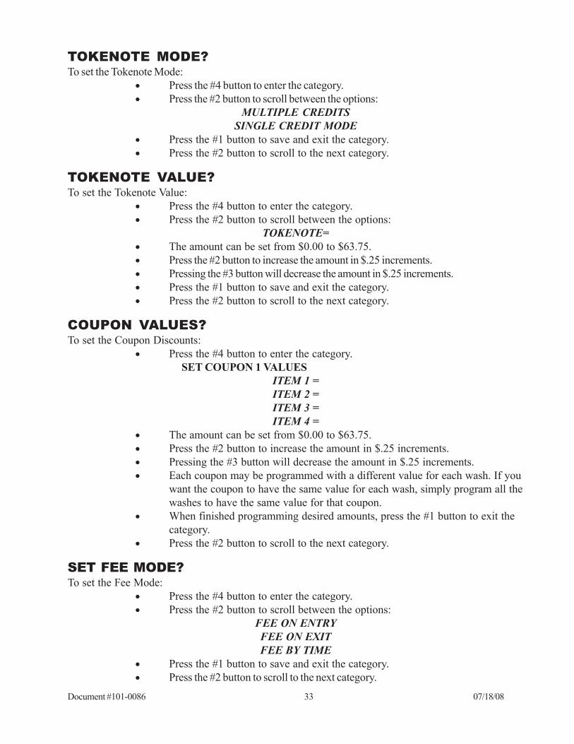
TOKENOTE MODE?To set the Tokenote Mode:
• Press the #4 button to enter the category.• Press the #2 button to scroll between the options:
MULTIPLE CREDITSSINGLE CREDIT MODE
• Press the #1 button to save and exit the category.• Press the #2 button to scroll to the next category.
TOKENOTE VALUE?To set the Tokenote Value:
• Press the #4 button to enter the category.• Press the #2 button to scroll between the options:
TOKENOTE=• The amount can be set from $0.00 to $63.75.• Press the #2 button to increase the amount in $.25 increments.• Pressing the #3 button will decrease the amount in $.25 increments.• Press the #1 button to save and exit the category.• Press the #2 button to scroll to the next category.
COUPON VALUES?To set the Coupon Discounts:
• Press the #4 button to enter the category. SET COUPON 1 VALUES
ITEM 1 =ITEM 2 =ITEM 3 =ITEM 4 =
• The amount can be set from $0.00 to $63.75.• Press the #2 button to increase the amount in $.25 increments.• Pressing the #3 button will decrease the amount in $.25 increments.• Each coupon may be programmed with a different value for each wash. If you
want the coupon to have the same value for each wash, simply program all thewashes to have the same value for that coupon.
• When finished programming desired amounts, press the #1 button to exit thecategory.
• Press the #2 button to scroll to the next category.
SET FEE MODE?To set the Fee Mode:
• Press the #4 button to enter the category.• Press the #2 button to scroll between the options:
FEE ON ENTRYFEE ON EXITFEE BY TIME
• Press the #1 button to save and exit the category.• Press the #2 button to scroll to the next category.

Document #101-0086 34 07/18/08
SET FEES?To set the parking rates:
• Press the #4 button to enter the category.• Press the #4 button to enter Event 0.• The display will read:
Base Fee = $0.00• Use the #2 & #3 buttons to scroll in $.25 increments to the desired price.• Press the #1 button to set the price.• Use the #2 & #3 buttons to toggle between EVENT 0 – 8.• Press the #4 button to enter the desired event.• The display will then show two categories:
Disabled Daily• The cursor will be flashing on the DISABLED side, press the #2 & #3 buttons
to toggle between DISABLED and ENABLED.• Press the #4 button to shift to DAILY.• The cursor will be flashing on the DAILY side, press the #2 & #3 buttons to
toggle between DAILY, WEEKLY, and SPECIAL.• Daily will give you the option of having the event occur each day at the time
set seven days a week.• Press the #4 button and the display will read:
Start: 00:00AM• With the cursor flashing on the second 0.• Press the #2 & #3 buttons to scroll between 0-12.• Press the #4 button to move to the minute side.• Press the #2 & #3 buttons to scroll between 0-59.• Press the #4 button to move to the AM/PM category.• Press the #2 & #3 buttons to scroll between AM and PM.• Press the #4 button and the display will read:
End: 00:00AM• The cursor will be flashing on the second 0.• Press the #2 & #3 buttons to scroll between 0-12.• Press the #4 button to move to the minute side.• Press the #2 & #3 buttons to scroll between 0-59.• Press the #4 button to move to the AM/PM category.• Press the #2 & #3 buttons to scroll between AM and PM.• Press the #4 button and the display will read:
Fee $0.25 Opened• The cursor will be flashing on the $ amount. Press the #2 & #3 button to
toggle in $.25 increments to set the desired fee.• Press the #4 button to shift to the opened column.• Press the #2 & #3 buttons to toggle between opened and closed (whether or
not the lot is opened or closed during this time period.• Press the #1 button to lock in these settings.• Continue programming events. Keep in mind that if you want to have one
event override another event, the event with the higher event number (0-9) willoverride a event with a lower number.
Document #101-0086 35 07/18/08
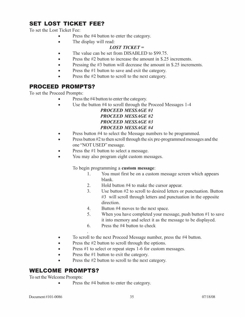
SET LOST TICKET FEE?To set the Lost Ticket Fee:
• Press the #4 button to enter the category.• The display will read:
LOST TICKET =• The value can be set from DISABLED to $99.75.• Press the #2 button to increase the amount in $.25 increments.• Pressing the #3 button will decrease the amount in $.25 increments.• Press the #1 button to save and exit the category.• Press the #2 button to scroll to the next category.
PROCEED PROMPTS?To set the Proceed Prompts:
• Press the #4 button to enter the category.• Use the button #4 to scroll through the Proceed Messages 1-4
PROCEED MESSAGE #1PROCEED MESSAGE #2PROCEED MESSAGE #3PROCEED MESSAGE #4
• Press button #4 to select the Message numbers to be programmed.• Press button #2 to then scroll through the six pre-programmed messages and the
one “NOT USED” message.• Press the #1 button to select a message.• You may also program eight custom messages.
To begin programming a custom message:1. You must first be on a custom message screen which appears
blank.2. Hold button #4 to make the cursor appear.3. Use button #2 to scroll to desired letters or punctuation. Button
#3 will scroll through letters and punctuation in the oppositedirection.
4. Button #4 moves to the next space.5. When you have completed your message, push button #1 to save
it into memory and select it as the message to be displayed.6. Press the #4 button to check.
• To scroll to the next Proceed Message number, press the #4 button.• Press the #2 button to scroll through the options.• Press #1 to select or repeat steps 1-6 for custom messages.• Press the #1 button to exit the category.• Press the #2 button to scroll to the next category.
WELCOME PROMPTS?To set the Welcome Prompts:
• Press the #4 button to enter the category.
Document #101-0086 36 07/18/08
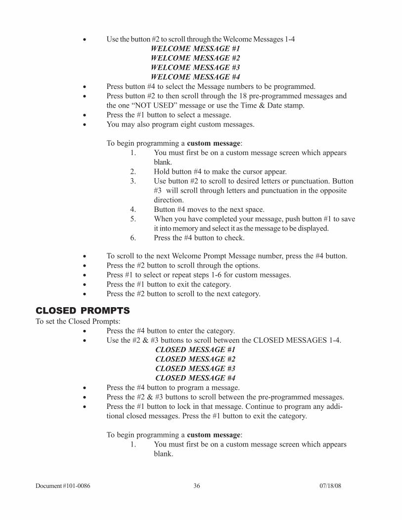
• Use the button #2 to scroll through the Welcome Messages 1-4WELCOME MESSAGE #1WELCOME MESSAGE #2WELCOME MESSAGE #3WELCOME MESSAGE #4
• Press button #4 to select the Message numbers to be programmed.• Press button #2 to then scroll through the 18 pre-programmed messages and
the one “NOT USED” message or use the Time & Date stamp.• Press the #1 button to select a message.• You may also program eight custom messages.
To begin programming a custom message:1. You must first be on a custom message screen which appears
blank.2. Hold button #4 to make the cursor appear.3. Use button #2 to scroll to desired letters or punctuation. Button
#3 will scroll through letters and punctuation in the oppositedirection.
4. Button #4 moves to the next space.5. When you have completed your message, push button #1 to save
it into memory and select it as the message to be displayed.6. Press the #4 button to check.
• To scroll to the next Welcome Prompt Message number, press the #4 button.• Press the #2 button to scroll through the options.• Press #1 to select or repeat steps 1-6 for custom messages.• Press the #1 button to exit the category.• Press the #2 button to scroll to the next category.
CLOSED PROMPTSTo set the Closed Prompts:
• Press the #4 button to enter the category.• Use the #2 & #3 buttons to scroll between the CLOSED MESSAGES 1-4.
CLOSED MESSAGE #1CLOSED MESSAGE #2CLOSED MESSAGE #3CLOSED MESSAGE #4
• Press the #4 button to program a message.• Press the #2 & #3 buttons to scroll between the pre-programmed messages.• Press the #1 button to lock in that message. Continue to program any addi-
tional closed messages. Press the #1 button to exit the category.
To begin programming a custom message:1. You must first be on a custom message screen which appears
blank.

Document #101-0086 37 07/18/08
2. Hold button #4 to make the cursor appear.3. Use button #2 to scroll to desired letters or punctuation. Button
#3 will scroll through letters and punctuation in the oppositedirection.
4. Button #4 moves to the next space.5. When you have completed your message, push button #1 to save
it into memory and select it as the message to be displayed.6. Press the #4 button to check.
• To scroll to the next Welcome Prompt Message number, press the #4 button.• Press the #2 button to scroll through the options.• Press #1 to select or repeat steps 1-6 for custom messages.• Press the #1 button to exit the category.• Press the #2 button to scroll to the next category.
EXT DISPLAY MSGS?To set the messages to appear on the External Display:
• Press the #4 button to enter the category.• The display will read:
MESSAGE #1 FIRST HALF
To begin programming this custom message:1. You must first be on a custom message which appears blank.2. Hold button #4 to make the cursor appear.3. Use button #2 to scroll to desired letters or punctuation. Button
#3 will scroll through letters and punctuation in the oppositedirection.
4. Button #4 moves to the next space.5. When you have completed your message, push button #1 to save
it into memory and select it as the message to be displayed.6. Press the #4 button to check.
• To scroll to the next message half, press the #4 button.• Repeat steps 1-6 for custom messages or press #2 to scroll to the “NOT
USED” message.• Press the #1 button to exit the category• Press the #2 button to scroll to the next category.
SET DATE & TIME?To set the Date & Time:
• Press the #4 button to enter the category.• The cursor will be flashing.• Press the #2 button to change the day.
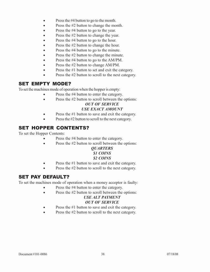
Document #101-0086 38 07/18/08
• Press the #4 button to go to the month.• Press the #2 button to change the month.• Press the #4 button to go to the year.• Press the #2 button to change the year.• Press the #4 button to go to the hour.• Press the #2 button to change the hour.• Press the #4 button to go to the minute.• Press the #2 button to change the minute.• Press the #4 button to go to the AM/PM.• Press the #2 button to change AM/PM.• Press the #1 button to set and exit the category.• Press the #2 button to scroll to the next category.
SET EMPTY MODE?To set the machines mode of operation when the hopper is empty:
• Press the #4 button to enter the category.• Press the #2 button to scroll between the options:
OUT OF SERVICEUSE EXACT AMOUNT
• Press the #1 button to save and exit the category.• Press the #2 button to scroll to the next category.
SET HOPPER CONTENTS?To set the Hopper Contents:
• Press the #4 button to enter the category.• Press the #2 button to scroll between the options:
QUARTERS$1 COINS$2 COINS
• Press the #1 button to save and exit the category.• Press the #2 button to scroll to the next category.
SET PAY DEFAULT?To set the machines mode of operation when a money acceptor is faulty:
• Press the #4 button to enter the category.• Press the #2 button to scroll between the options:
USE ALT PAYMENTOUT OF SERVICE
• Press the #1 button to save and exit the category.• Press the #2 button to scroll to the next category.

Document #101-0086 39 07/18/08
SET REFUND ENABLE?To set the status of the Refund Button :
• Press the #4 button to enter the category.• The display will read:
REFUND=• Press the #2 button to scroll between the options:
ENABLEDISABLE
• Press the #1 button to exit the category.
RECEIPT HEADERS?To set the Receipt Headers:
• Press the #4 button to enter the category.• Up to eight lines of text may be selected.• Press the #2 button to scroll between the options:
NOT USEDCUSTOM
To begin programming a custom message:1. You must first be on a custom message screen which appearsblank.2. Hold button #4 to make the cursor appear.3. Use button #2 to scroll to desired letters or punctuation. Button
#3 will scroll through letters and punctuation in the oppositedirection.
4. Button #4 moves to the next space.5. When you have completed your message, push button #1 to save
it into memory and select it as the message to be displayed.6. Press the #4 button to check.
• To scroll to the next line, press the #4 button.• Press the #2 button to scroll through the options.• Press #1 to select or repeat steps 1-6 for custom messages.• Press the #1 button to exit the category.• Press the #2 button to scroll to the next category.
SET RECEIPT MODE?To set the Receipt Mode:
• Press the #4 button to enter the category.• Press the #2 button to scroll between the options:
NEVERALWAYS PRINT
ASK• Press the #1 button to save and exit the category.• Press the #2 button to scroll to the next category.
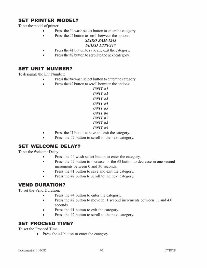
Document #101-0086 40 07/18/08
SET PRINTER MODEL?To set the model of printer:
• Press the #4 wash select button to enter the category.• Press the #2 button to scroll between the options:
SEIKO SAM-1245SEIKO LTPF247
• Press the #1 button to save and exit the category.• Press the #2 button to scroll to the next category.
SET UNIT NUMBER?To designate the Unit Number:
• Press the #4 wash select button to enter the category.• Press the #2 button to scroll between the options:
UNIT #1UNIT #2UNIT #3UNIT #4UNIT #5UNIT #6UNIT #7UNIT #8UNIT #9
• Press the #1 button to save and exit the category.• Press the #2 button to scroll to the next category.
SET WELCOME DELAY?To set the Welcome Delay:
• Press the #4 wash select button to enter the category.• Press the #2 button to increase, or the #3 button to decrease in one second
increments between 0 and 30 seconds.• Press the #1 button to save and exit the category.• Press the #2 button to scroll to the next category.
VEND DURATION?To set the Vend Duration:
• Press the #4 button to enter the category.• Press the #2 button to move in .1 second increments between .1 and 4.0
seconds.• Press the #1 button to exit the category.• Press the #2 button to scroll to the next category.
SET PROCEED TIME?To set the Proceed Time:
• Press the #4 button to enter the category.

Document #101-0086 41 07/18/08
• Press the #2 & #3 buttons to select between 1 and 9.9 seconds increasing by .1 secondincrements.
• Press the #1 to exit category
TOTAL DEPOSITS?To view the Total Deposits:
• Press the #4 button to enter the category.• Press the #2 button to scroll between the options:
CASH =TOKENS =CARDS =
• Press the #1 button to exit the category.• Press the #2 button to scroll to the next category.
TOTAL VENDING?To view the Total Vending:
• Press the #4 button to enter the category.• Press the #2 button to scroll between the option:
EVENT 1 CNTEVENT 1 CSHEVENT 1 TOKEVENT 1 DEBEVENT 2 CNTEVENT 2 CSHEVENT 2 TOKEVENT 2 DEBEVENT 3 CNTEVENT 3 CSHEVENT 3 TOKEVENT 3 DEBEVENT 4 CNTEVENT 4 CSHEVENT 4 TOKEVENT 4 DEB
• Press the #1 button to exit the category.• Press the #2 button to scroll to the next category.
TOTAL OVERPAID?To view the Total Overpaid:
• Press the #4 button to enter the category.• The display will read:
OVERPAID $• Press the #1 button to exit the category.• Press the #2 button to scroll to the next category.

Document #101-0086 42 07/18/08
TOTAL VAULT COUNT?To view the Total Vault Count:
• Press the #4 button to enter the category.• Press the #2 button to scroll between the options:
$20 BILL CNT$10 BILL CNT$5 BILL CNT$2 COIN CNT$1 BILL CNT$1 COIN CNT
QUARTER CNTTOKEN CNT
TOKENOTE CNTCOUPON 1 CNTCOUPON 2 CNTCOUPON 3 CNTCOUPON 4 CNT
CARD CNTHOPPER CNT
• Press the #1 button to exit the category.

Document #101-0086 43 07/18/08
VII. MAINTENANCEA few simple maintenance routines can extend the productivity of the Autocashier.
CAUTION! DO NOT USE OIL, GREASE OR SOLVENTS ON ANYPART OF THIS UNIT EXCEPT AS CLEARLY SPECIFIED IN THISMANUAL, THE HOPPER, VALIDATOR, OR STACKER MANUAL.
MONTHLY MAINTENANCEHopperThe hopper should be cleaned at least every other month. To do so, please refer to the Hamilton HSHHopper Operational Manual.
ValidatorPlease refer to the appropriate validator manual.
StackerPlease refer to the appropriate manual.
ANNUAL MAINTENANCEHamilton ValidatorsThe validator should be serviced annually to maintain maximum performance. This work should onlybe done by a trained technician.
Hamilton Stackers• All pivot points must be cleaned and re-greased.• Check the switch tightness and the cam to see if it is still in round.• Check for bent, loose, worn, rusted or corroded parts.• Check the motor for coasting.• Use a small amount of Dry Slick™ on the slides. Do not use grease or
WD-40™.

Document #101-0086 44 07/18/08
VIII. ERROR CODESThe GL-ACW-P is equipped with a self-diagnostic capability that makes it possible for common problems tobe quickly detected and serviced. When most errors occur, the controller will automatically shut down theentire unit as a precaution in order to prevent further malfunctions. When the GL-ACW-P shuts itself downafter an error has been detected, it deactivates the bill acceptor and coin acceptors so that further depositscannot be accepted. When this occurs, the display will read:
OUT OF SERVICE
It is necessary to troubleshoot and correct the problem before normal operation can resume. Shuttingoff power to the unit will not erase this error condition. To resume normal operation, it is necessaryto:
1. Acknowledge that you have seen the error. To do this, press the YEL-LOW button on the controller. When this button is pressed the displaywill show the detected error. (Possible errors and their descriptions arecovered later in this section.)
2. After making note of the error and correcting the problem, it is neces-sary to once again press the YELLOW button to return to normaloperation. When this button is pressed the display will read:
ERROR ACKNOWLEDGED
3. The display will then return to the welcome prompt.
It is possible for the GL-ACW-P to detect an error and still remain operational. This occurs when thedefault payment mode has been set to “USE ALT PAYMENT” instead of “OUT OF SERVICE”. In the“USE ALT PAYMENT” mode, the controller will only shut down the component that is malfunction-ing. The controller will stop displaying the normal Welcome Messages and instead display the mes-sages “PAYMENT OPTIONS…” and “USE BILLS ONLY” (depending on which payment options areavailable). When all the payment options have been exhausted, the GL-ACW-P will shut down anddisplay an error message for the last component malfunction. When this occurs, follow the above stepsto return to normal operation.
ERROR CODES$5 Input StuckWhen signaling that a $5, $10 or a $20 bill has been accepted this line gets pulled low briefly. If the $5line should get pulled low for an extended period of time, this error will result and the machine will beshut down.
$1 Input StuckWhen signaling that a $1 bill has been accepted this line gets pulled low briefly. If the $1 line shouldget pulled low for an extended period of time, this error will result and the machine will be shut down.

Document #101-0086 45 07/18/08
25¢ Input StuckWhen signaling that a quarter has been accepted this line gets pulled low briefly. If the Quarter lineshould get pulled low for an extended period of time, this error will result and the machine will be shutdown.
Token Input StuckWhen signaling that a token coin has been accepted this line gets pulled low briefly. If the Token lineshould get pulled low for an extended period of time, this error will result and the machine will be shutdown.
Drop Switch StuckWhen signaling that a coin is being dispensed this line gets pulled high briefly. If the Drop line shouldget pulled high for an extended period of time, this error will result and the machine will be shut down.This situation is only tested during the time a payout is occurring.
Unexpected Coin DropWhen a coin is dispensed, the Drop line goes high briefly, then returns to its logic low state. If thecontroller records two unexpected coin drop signals while in standby, the machine will shut down withthis error.
Hopper Coasting ErrorIf two coin drop signals are recorded immediately after the hopper has paid out, the machine will shutdown with this error.
Hopper Time-outWhen a coin is dispensed, the Drop line goes high briefly then returns to its logic low state. If duringthe time a payout is occurring a high pulse is not detected for 10 consecutive seconds this error willresult and the machine will be shut down.
Stacker Time-outThe Busy line goes high during the bill stacking process then returns to its logic low state when thestacker reaches its home position. If the stacker never returns to its home position, this error will resultand the machine will be shut down.
Multiple Power IntThere is special circuitry inside the controller to determine if a power outage has occurred. If there areseveral power outages while processing money (dispensing coins, stacking bills, etc.) this error willoccur and the machine will be shut down.
Memory Data Altered!There are special detection routines built into the Controller’s program that can determine if its memoryhas been corrupted. If the memory is corrupted, values such as wash prices and the audits can no longerbe trusted. If this should occur, the entire memory is cleared and the machine will be shut down.Reprogramming the controller will be necessary since all settings will default to the lowest possibledenomination ($0.00) for credits and the highest possible denomination ($63.75) for any paymentoption. This default mechanism is used as a safeguard to ensure that the machine does not give away freewashes. The following errors will be displayed as long as the faulty condition exists, but will be cleared as soon

Document #101-0086 46 07/18/08
as the condition is corrected. THIS MEANS THESE ERRORS DO NOT NEED TO BE ACKNOWL-EDGED BY PRESSING THE YELLOW BUTTON.
Hopper EmptyWhen there are not enough coins to make a connection from the bottom of the hopper up to the twocoin sensing plates in the hopper bowl, the Empty line goes high. When this happens, the HopperEmpty error will result. Refilling the hopper with coins will automatically clear this error.
Release ButtonWhen one of the item selection buttons is held in for an extended period of time this message willappear on the display. Releasing the button should automatically clear this error. If the error does notclear, however, it could indicate the REFUND button is broken or stuck. Dislodge or replace the buttonto remedy this error. If the error still does not clear, there may be damage to the CPU, in which case youshould contact the Hamilton Customer Service Department for assistance.

Document #101-0086 47 07/18/08
SITUATION PROBABLE CAUSE CORRECTIONS
• Cannot activate refund
A. In “USE EXACT AMOUNT”
mode
A. Fill coin Hopper or change
mode to “OUT OF SERVICE”
• Credit is showing on
display
B. Selection buttons are not
working
B. Replace button
C. CPU input is missing C. Contact the factory for
assistance
• Accepts fee, but car
wash does not start
• “DRIVE AHEAD” or
similar message shown on
ACW Display
A. Duration of relay closure is too
long or too short for wash
equipment to recognize
A. Reprogram “VEND
DURATION” setting in ACW
Controller
B. Wash equipment is not
accepting signal from ACW
B. Refer to the car wash manual
C. Broken connection in wiring
between ACW and wash
equipment
C. Locate and repair connection
A. Vend relay is loose or
defective
A. Reinstall or replace relay
B. Broken connection in wiring
between ACW Controller and relay
panel
B. Locate and repair connection
C. Output missing from
Controller
C. Contact the factory for
assistance
A. Broken connection on power
wires to Coin Acceptor
A. Locate and repair connection
B. Coin Acceptor sensitivity is
too high
B. Adjust sensitivity
C. Coin Acceptor is defective C. Replace Coin Acceptor
One Coin Acceptor does not
accept coins
Observe the VEND RELAYS and see
below
Observe the VEND RELAYS and see
below
IF THE RELAY ACTIVATES…
IF RELAY DOES NOT
ACTIVATE…
IX. TROUBLESHOOTINGIn addition to the self-diagnostic error codes, there are other possibilities that could arise in the instal-lation or at some point during the extended operation of your GL-ACW-P. This section provides ageneral troubleshooting guide, broken down into categories of symptoms.
Money Acceptance
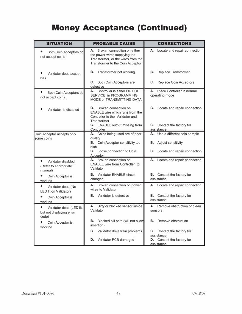
Document #101-0086 48 07/18/08
Money Acceptance (Continued)
SITUATION PROBABLE CAUSE CORRECTIONS
• Both Coin Acceptors do
not accept coins
A. Broken connection on either
the power wires supplying the
Transformer, or the wires from the
Transformer to the Coin Acceptor
A. Locate and repair connection
• Validator does accept
bills
B. Transformer not working B. Replace Transformer
C. Both Coin Acceptors are
defective
C. Replace Coin Acceptors
• Both Coin Acceptors do
not accept coins
A. Controller is either OUT OF
SERVICE, in PROGRAMMING
MODE or TRANSMITTING DATA
A. Place Controller in normal
operating mode
• Validator is disabled
B. Broken connection on
ENABLE wire which runs from the
Controller to the Validator and
Transformer
B. Locate and repair connection
C. ENABLE output missing from
Controller
C. Contact the factory for
assistance
A. Coins being used are of poor
quality
A. Use a different coin sample
B. Coin Acceptor sensitivity too
high
B. Adjust sensitivity
C. Loose connection to Coin
Acceptor
C. Locate and repair connection
• Validator disabled
(Refer to appropriate
manual)
A. Broken connection on
ENABLE wire from Controller to
Validator
A. Locate and repair connection
• Coin Acceptor is
working
B. Validator ENABLE circuit
changed
B. Contact the factory for
assistance
• Validator dead (No
LED lit on Validator)
A. Broken connection on power
wires to Validator
A. Locate and repair connection
• Coin Acceptor is
working
B. Validator is defective B. Contact the factory for
assistance
• Validator dead (LED lit,
but not displaying error
code)
A. Dirty or blocked sensor inside
Validator
A. Remove obstruction or clean
sensors
• Coin Acceptor is
working
B. Blocked bill path (will not allow
insertion)
B. Remove obstruction
C. Validator drive train problems C. Contact the factory for
assistance
D. Validator PCB damaged D. Contact the factory for
assistance
Coin Acceptor accepts only
some coins
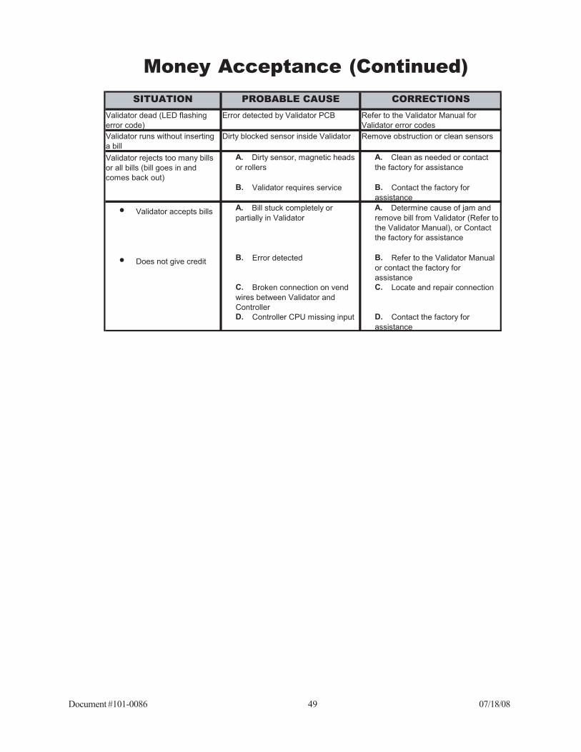
Document #101-0086 49 07/18/08
SITUATION PROBABLE CAUSE CORRECTIONS
Validator dead (LED flashing
error code)
Error detected by Validator PCB Refer to the Validator Manual for
Validator error codes
Validator runs without inserting
a bill
Dirty blocked sensor inside Validator Remove obstruction or clean sensors
A. Dirty sensor, magnetic heads
or rollers
A. Clean as needed or contact
the factory for assistance
B. Validator requires service B. Contact the factory for
assistance
• Validator accepts bills
A. Bill stuck completely or
partially in Validator
A. Determine cause of jam and
remove bill from Validator (Refer to
the Validator Manual), or Contact
the factory for assistance
• Does not give credit
B. Error detected B. Refer to the Validator Manual
or contact the factory for
assistance
C. Broken connection on vend
wires between Validator and
Controller
C. Locate and repair connection
D. Controller CPU missing input D. Contact the factory for
assistance
Validator rejects too many bills
or all bills (bill goes in and
comes back out)
Money Acceptance (Continued)

Document #101-0086 50 07/18/08
SITUATION PROBABLE CAUSE CORRECTION
A. Wash prices set incorrectly A. Check wash prices
B. Hopper not counting coins B. Perform HOPPER PAYOUT
TEST (Refer to the Hopper
Manual)
• Hopper does not run
A. Coin or foreign material
lodged in Hopper
A. Clear obstruction in Hopper
• Hopper does not pay
back change
B. Broken connection in wire
between Controller and Hopper
motor
B. Locate and repair connection
C. Output missing from
Controller
C. Contact the factory for
assistance
A. Foreign material in Hopper A. Remove foreign material
B. Output weak from Controller B. Contact the factory for
assistance
• Underpayment of
change
A. Wash prices set incorrectly A. Check wash prices
• Controller does not go
into “OUT OF SERVICE”
B. Coins fall back into Hopper
after counting
B. Perform HOPPER PAYOUT
TEST (Refer to the Hopper
Manual)
C. CPU misreads coin count C. Contact the factory for
assistance
• Underpayment of
change
• Controller does go into
“OUT OF SERVICE”
Error detected by Controller (See
ERROR CODES)
Correct malfunction, acknowledge
error
Overpayment of change
Hopper runs slowly
Hopper
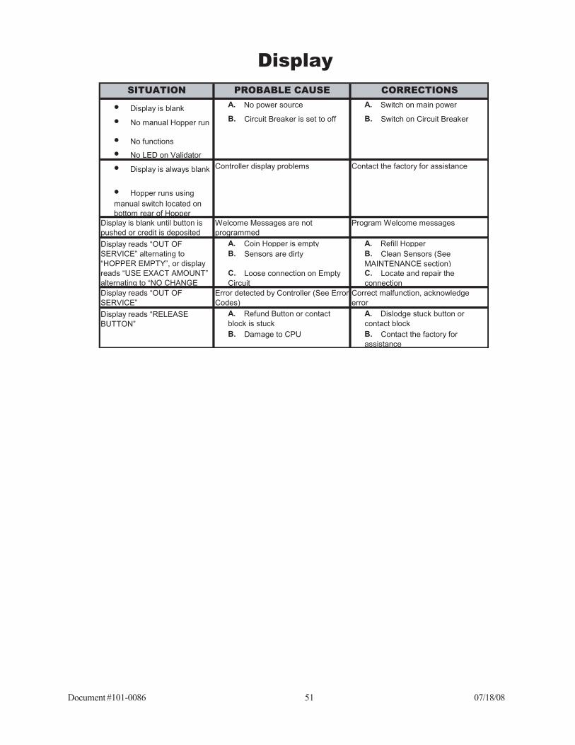
Document #101-0086 51 07/18/08
SITUATION PROBABLE CAUSE CORRECTIONS
• Display is blank
A. No power source A. Switch on main power
• No manual Hopper run
B. Circuit Breaker is set to off B. Switch on Circuit Breaker
• No functions
• No LED on Validator
• Display is always blank
• Hopper runs using
manual switch located on
bottom rear of Hopper
Display is blank until button is
pushed or credit is deposited
Welcome Messages are not
programmed
Program Welcome messages
A. Coin Hopper is empty A. Refill Hopper
B. Sensors are dirty B. Clean Sensors (See
MAINTENANCE section)
C. Loose connection on Empty
Circuit
C. Locate and repair the
connection
Display reads “OUT OF
SERVICE”
Error detected by Controller (See Error
Codes)
Correct malfunction, acknowledge
error
A. Refund Button or contact
block is stuck
A. Dislodge stuck button or
contact block
B. Damage to CPU B. Contact the factory for
assistance
Display reads “OUT OF
SERVICE” alternating to
“HOPPER EMPTY”, or display
reads “USE EXACT AMOUNT”
alternating to “NO CHANGE
Display reads “RELEASE
BUTTON”
Controller display problems Contact the factory for assistance
Display
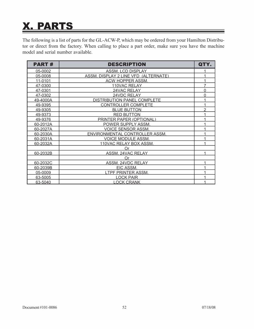
Document #101-0086 52 07/18/08
X. PARTSThe following is a list of parts for the GL-ACW-P, which may be ordered from your Hamilton Distribu-tor or direct from the factory. When calling to place a part order, make sure you have the machinemodel and serial number available.
PART # DESCRIPTION QTY.
05-0002 ASSM, LCD DISPLAY 105-0008 ASSM, DISPLAY 2 LINE VFD (ALTERNATE) 111-0101 ACW HOPPER ASSM. 147-0300 110VAC RELAY 747-0301 24VAC RELAY 047-0302 24VDC RELAY 0
49-4000A DISTRIBUTION PANEL COMPLETE 149-9395 CONTROLLER COMPLETE 149-9305 BLUE BUTTON 249-9373 RED BUTTON 149-9376 PRINTER PAPER (OPTIONAL) 1
60-2012A POWER SUPPLY ASSM. 160-2027A VOICE SENSOR ASSM. 160-2030A ENVIRONMENTAL CONTROLLER ASSM. 160-2031A VOICE MODULE ASSM. 160-2032A 110VAC RELAY BOX ASSM. 1
Or60-2032B ASSM, 24VAC RELAY 1
Or60-2032C ASSM, 24VDC RELAY 160-2039B EIC ASSM. 105-0009 LTPF PRINTER ASSM. 163-5005 LOCK PAIR 163-5040 LOCK CRANK 1

Document #101-0086 53 07/18/08
Part # Description Qty 60-2053 Security Bracket 1 90-0145 #8-32 X 5/8 Phillips Head Screw 4 90-0331 #1/4-20 Hex Nut 4 90-0403 #1/4 Internal Lock Washer 4 60-2051 U-Channel 1 90-0629 #10-32 x ½ Thumb Screw 1 60-2050 Validator Plate 1 90-0321 #8-32 Nylon Nut 4 60-2054 Slider 1 90-0517 #8-32 x 5/8 Ball Stud 4 90-0628 #10-32 x 3/16 Phillister 4 46-0169 Validator Coinco 24v 1 48-3044 ACW G/L Coinco 24v cable 1 48-3046 ACW G/L 3rd Party Stacker 1
Part # Description Qty 60-2055 Security Bracket 1 90-0145 #8-32 x 5/8 Phillips Head Screw 4 90-0331 #1/4-20 Hex Nut 4 90-0403 #1/4 Internal Lock Washer 4 60-2051 U-Channel 1 90-0629 #10-32 x ½ Thumb Screw 1 60-2050 Validator Plate 1 90-0321 #8-32 Nylon 4 60-2052 UVM Slider 1 90-0517 #8-32 x 5/8 Ball Stud 4 90-0628 #10-32 x 3/16 Phillister Head 4 46-0201 Validator Mars 24v 1 48-3043 ACW G/L Mars 24v cable 1 48-3046 ACW G/L 3rd Party Stacker 1
Interchanging ValidatorsTo replace an existing validator with a Coinco® Validator, the following parts are needed. The Co-inco® mounting kit is part #60-2103B. Please note the Coinco® Validator (part #46-0169) is not in-cluded in the kit and must be purchased separately.
To replace an existing validator with a Mars® Validator, the following parts are needed. The Mars®mounting kit is part #60-2104B. Please note the Mars® Validator (part #46-0201) is not included in thekit and must be purchased separately.

Document #101-0086 54 07/18/08
XI. OPTIONAL RECEIPT PRINTER
Safety Precautions••••• The motor is hot immediately after printing. Allow cooling before handling.••••• The edge of the mechanism is sharp, use caution when handling.
Inserting PaperLoading PaperAutomatic paper loading operation:1. Open platen by lifting blue lever on right side of printer. (Be sure to hold platen to prevent it
from swinging down when released.)
Figure 11-1 Figure 11-22. Remove printer rod and place in center of paper roll and replace on platen.
Figure 11-3

Document #101-0086 55 07/18/08
3. Unroll about 4 inches of paper and center on roller and close the platen by rotating it upward andsliding it back until it snaps into position.
Figure 11-44. Push button to ensure straight feed and tear off by pulling down on excess.
Figure 11-5
Clearing a Paper Jam in the AutocutterIf the cutter has been locked during paper cutting, power off the motor immediately and cancel the lockby performing the following procedures manually:
1. Tear transparent film from the upper surface of the autocutter (figure 11-6A), turn the knob inthe direction shown in figure 11-6B until the entire hole of the warm wheel can be seen fromthe standby position confirmation window and retreat the moveable blade. (Figure 11-6B)

Document #101-0086 56 07/18/08
A
BC
Figure 11-6
Head Cleaning Precautions and ProcedureCleaning Precautions1. Do not clean the head directly after printing because the thermal head and its periphery are
hot during and after printing.
2. Do not use sandpaper, paper knife etc. when cleaning as it could damage the heat elements.
Cleaning Procedure:1. Turn over the lever to the direction of the arrow in figure 11-7. Pull up the platen after mak-
ing sure that the platen is released from the lever. (Open state)
2. Clean the heat elements with a cotton swab immersed in ethyl alcohol or isopropyl alcohol.
3. After the alcohol has completely dried, close the platen. (Closed state)
Figure 11-7

Document #101-0086 57 07/18/08
THERMAL PAPER SPECIFICATIONSModel TF50KS-E2C: Normal thermal paper PD160R-N: Medium proof paperHP220AB1: Medium proof paper
• 58 -1 mm Paper width

Document #101-0086 58 07/18/08
XII. EIC COMMUNICATION PANELThe External Interface controller contains a 386 processor and modem, which is used for processing creditcard transactions. The EIC allows communication with external equipment. See Figures 12-1 and 12-2.
Figure 12-1 EIC Left Side View
HAND-HELD

Document #101-0086 59 07/18/08
Figure 12-2 EIC Front View
PRINTER: Optional parallel port printer to print credit reports.TELCO: Outside telephone line. Connect to a dedicated telephone line for credit card processingand remote maintenance.EIC Interface: This connects to P10 on the distribution panel.
PRINTERTEL CO
EIC INTERFACE

Document #101-0086 60 07/18/08
XIII. TOKENOTES®A Tokenote® is a paper coupon that can be accepted by the Hamilton Validator. It is intended to give credittowards the wash price and not as a substitute for cash. Because of this, change will not be dispensed if thevalue of a Tokenote® exceeds the wash price. Likewise, the value of a Tokenote® cannot be refunded incash.
It is important to realize that accepted Tokenotes® will issue a programmableamount of credit good towards all wash selections. Tokenote® use cannot belimited to a specific wash or subset of washes.
These must be specially ordered from Hamilton Mfg. or your Hamilton Distributor.
When programming your machine to accept Tokenotes®, refer to the options listed below to help youdecide which programming method to use.
Programming One or More Tokenotes® with the Same Value
PROGRAMMING THE STA VALIDATOR:1. With the power on, check the operation of the validator. A dot flashing
on the LED indicates it is operating normally.2. Note the position of each switch on the DIP switch. (The DIP switch is
located on the side of the validator.)3. Set all 8 DIP switches to the OFF position. Then, starting with switch
#8, slowly move the switches to the ON position, one switch at a timeand in descending order (8, 7, 6, 5…). The LED should now be flash-ing the letter “P”. This signifies that the validator is in the Tokenote®Programming Mode.
4. At this point, it is recommended to insert the CLEAR ALL TrainingCoupon, especially if this is the first time the validator is being pro-grammed or if it has just been returned after being serviced. TheCLEAR ALL Coupon will erase all previously trained Tokenotes®from the validator’s memory but will not affect the controller’smemory.
5. Insert one coded Tokenote® into the validator, making sure that it isaccepted.
6. Repeat step 5 for each uniquely coded Tokenote® you wish to pro-gram. (Make sure that each Tokenote® is equal in value.) Up to 15different codes can be programmed.
7. Starting with switch #1, slowly move the switches back to their origi-nal positions one at a time. This must be done in ascending order (1, 2,3, 4…). A dot should now be flashing on the LED. Switch #2 must bein the OFF position in order to accept Tokenotes®.

Document #101-0086 61 07/18/08
PROGRAMMING THE HVX or XE VALIDATOR:1. With the power on, check the operation of the validator. A dot flashing
on the LED indicates it is operating normally.2. Note the position of each switch on the DIP switch. (The DIP switch is
located on the side of the validator.)3. Set all 10 DIP switches to the OFF position. Then, starting with switch
#10, slowly move the switches to the ON position, one switch at a timeand in descending order (10, 9, 8, 7…). The LED should now beflashing the letter “P”. This signifies that the validator is in the To-kenote® Programming Mode.
4. At this point, it is recommended to insert the CLEAR ALL TrainingCoupon, especially if this is the first time the validator is being pro-grammed or if it has just been returned after being serviced. TheCLEAR ALL Coupon will erase all previously trained Tokenotes®from the validator’s memory but will not affect the controller’smemory.
5. Insert one coded Tokenote® into the validator, making sure that it isaccepted.
6. Repeat step 5 for each uniquely coded Tokenote® you wish to pro-gram. (Make sure that each Tokenote® is equal in value.) Up to 14different codes can be programmed.
7. Starting with switch #1, slowly move the switches back to their origi-nal positions one at a time. This must be done in ascending order (1, 2,3, 4…). A dot should now be flashing on the LED. Switch #2 must bein the OFF position in order to accept Tokenotes®.
PROGRAMMING THE CONTROLLER:You must set the Tokenote® Value:
• Push the top and bottom buttons on the ACW Controller simulta-neously for about 3-5 seconds to enter the programming mode.
• You must use the four wash select buttons and the refund buttonlocated on the door. For ease of reference, the top blue button will be#1. The second down will be #2, the third will be #3 and the bottomwill be known as #4.
• Press the #2 button to scroll to the TOKENOTE VALUE? category.• Press the #4 button to enter the category.• Press the #2 button to scroll between the options:
TOKENOTE=• The amount can be set from $0.00 to $63.75.• Press the #2 button to increase the amount in $.25 increments.• Pressing the #3 button will decrease the amount in $.25 increments.• Press the #1 button to exit the category.• Press the #2 button to scroll to the next category.

Document #101-0086 62 07/18/08
Programming Two Or More Tokenotes® With Different Values
You will need:1. Training Coupons - Training Coupons are used to program Tokenotes® into the Validator’s
memory. There are four different Training Coupons: Coupon #1, Coupon #2, Coupon #3, andCoupon #4.
2. Clear All Coupon – The CLEAR ALL Coupon is used to erase all previously trained To-kenotes® so that the validator will no longer accept any of those Tokenotes®.
The following table shows the different types of Training Coupons needed to successfully programTokenotes® on an Autocashier.
PROGRAMMING THE STA VALIDATOR:1. With the power on, check the operation of the validator. A dot flashing
on the LED indicates it is operating normally.2. Note the position of each switch on the DIP switch. (The DIP switch is
located on the side of the validator.)3. Set all 8 DIP switches to the OFF position. Then, starting with switch
#8, slowly move the switches to the ON position, one switch at a timeand in descending order (8, 7, 6, 5…). The LED should now be flash-ing the letter “P”. This signifies that the validator is in the Tokenote®Programming Mode.
4. At this point, it is recommended to insert the CLEAR ALL TrainingCoupon, especially if this is the first time the validator is being pro-grammed or if it has just been returned after being serviced. TheCLEAR ALL Coupon will erase all previously trained Tokenotes®from the validator’s memory but will not affect the controller’smemory.
5. Insert one coded Tokenote® into the validator, making sure that it isaccepted.
Training Coupon Type Usage
COUPON #1 Used to program credit for Coupon #1 discount
COUPON #2 Used to program credit for Coupon #2 discount
COUPON #3 Used to program credit for Coupon #3 discount
COUPON #4 Used to program credit for Coupon #4 discount
CLEAR ALL
Used to erase all trained Tokenotes® so that the
Validator will no longer accept any Tokenotes®
NULL
Used to accept a particular Tokenote® without
giving credit for it (such as an expired note)
CLEAR ONE
Used to erase one or more trained Tokenotes® so
that the Validator will no longer accept cleared
Tokenotes®
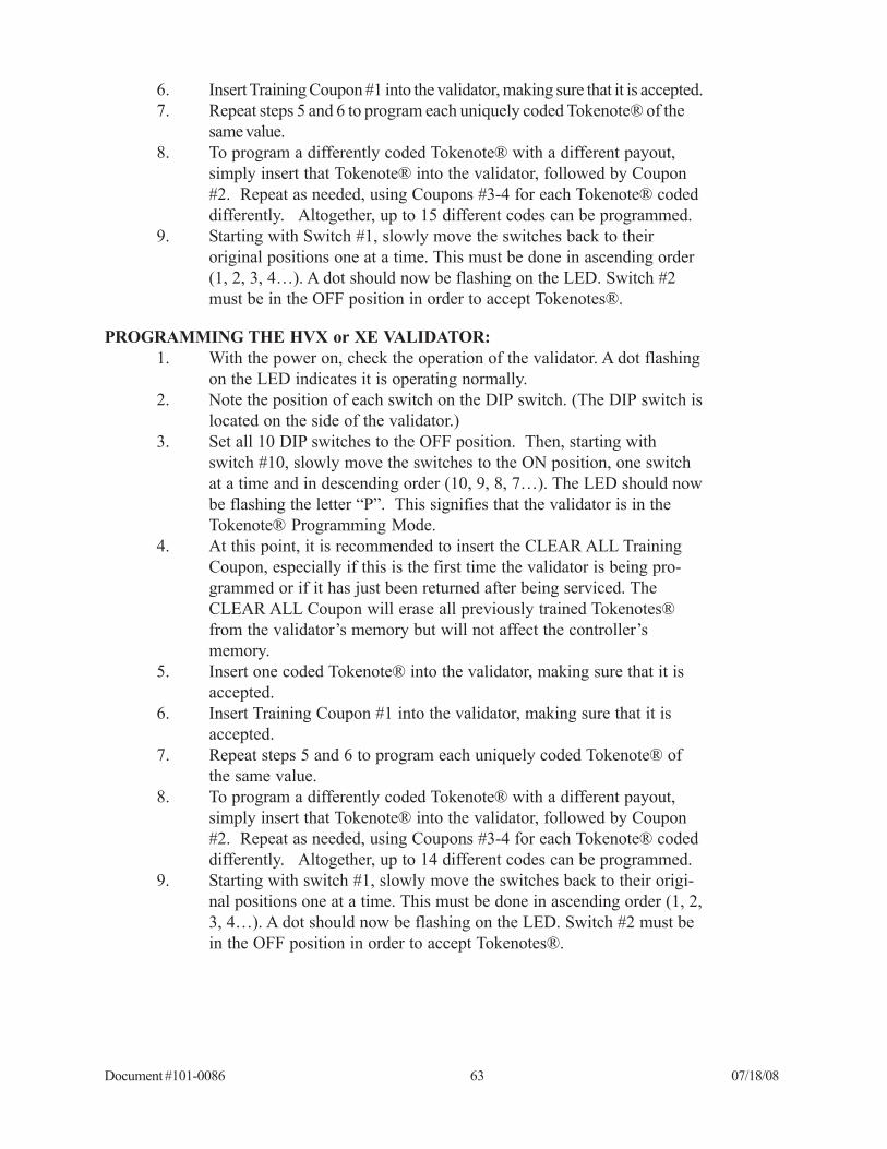
Document #101-0086 63 07/18/08
6. Insert Training Coupon #1 into the validator, making sure that it is accepted.7. Repeat steps 5 and 6 to program each uniquely coded Tokenote® of the
same value.8. To program a differently coded Tokenote® with a different payout,
simply insert that Tokenote® into the validator, followed by Coupon#2. Repeat as needed, using Coupons #3-4 for each Tokenote® codeddifferently. Altogether, up to 15 different codes can be programmed.
9. Starting with Switch #1, slowly move the switches back to theiroriginal positions one at a time. This must be done in ascending order(1, 2, 3, 4…). A dot should now be flashing on the LED. Switch #2must be in the OFF position in order to accept Tokenotes®.
PROGRAMMING THE HVX or XE VALIDATOR:1. With the power on, check the operation of the validator. A dot flashing
on the LED indicates it is operating normally.2. Note the position of each switch on the DIP switch. (The DIP switch is
located on the side of the validator.)3. Set all 10 DIP switches to the OFF position. Then, starting with
switch #10, slowly move the switches to the ON position, one switchat a time and in descending order (10, 9, 8, 7…). The LED should nowbe flashing the letter “P”. This signifies that the validator is in theTokenote® Programming Mode.
4. At this point, it is recommended to insert the CLEAR ALL TrainingCoupon, especially if this is the first time the validator is being pro-grammed or if it has just been returned after being serviced. TheCLEAR ALL Coupon will erase all previously trained Tokenotes®from the validator’s memory but will not affect the controller’smemory.
5. Insert one coded Tokenote® into the validator, making sure that it isaccepted.
6. Insert Training Coupon #1 into the validator, making sure that it isaccepted.
7. Repeat steps 5 and 6 to program each uniquely coded Tokenote® ofthe same value.
8. To program a differently coded Tokenote® with a different payout,simply insert that Tokenote® into the validator, followed by Coupon#2. Repeat as needed, using Coupons #3-4 for each Tokenote® codeddifferently. Altogether, up to 14 different codes can be programmed.
9. Starting with switch #1, slowly move the switches back to their origi-nal positions one at a time. This must be done in ascending order (1, 2,3, 4…). A dot should now be flashing on the LED. Switch #2 must bein the OFF position in order to accept Tokenotes®.
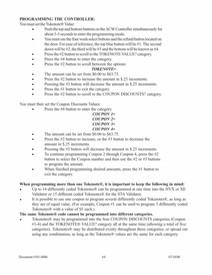
Document #101-0086 64 07/18/08
PROGRAMMING THE CONTROLLER:You must set the Tokenote® Value:
• Push the top and bottom buttons on the ACW Controller simultaneously forabout 3-5 seconds to enter the programming mode.
• You must use the four wash select buttons and the refund button located onthe door. For ease of reference, the top blue button will be #1. The seconddown will be #2, the third will be #3 and the bottom will be known as #4.
• Press the #2 button to scroll to the TOKENOTE VALUE? category.• Press the #4 button to enter the category.• Press the #2 button to scroll between the options:
TOKENOTE=• The amount can be set from $0.00 to $63.75.• Press the #2 button to increase the amount in $.25 increments.• Pressing the #3 button will decrease the amount in $.25 increments.• Press the #1 button to exit the category.• Press the #2 button to scroll to the COUPON DISCOUNTS? category.
You must then set the Coupon Discounts Values:• Press the #4 button to enter the category.
COUPON 1=COUPON 2=COUPON 3=COUPON 4=
• The amount can be set from $0.00 to $63.75.• Press the #2 button to increase, or the #3 button to decrease the
amount in $.25 increments.• Pressing the #3 button will decrease the amount in $.25 increments.• To continue programming Coupon 2 through Coupon 4, press the #2
button to select the Coupon number and then use the #2 or #3 buttonsto program the amount.
• When finished programming desired amounts, press the #1 button toexit the category.
When programming more than one Tokenote®, it is important to keep the following in mind:♦ Up to 14 differently coded Tokenotes® can be programmed at one time into the HVX or XE
Validator or 15 different coded Tokenotes® for the STA Validator.♦ It is possible to use one coupon to program several differently coded Tokenotes®, as long as
they are of equal value. (For example, Coupon #1 can be used to program 3 differently codedTokenotes® with a value of $5 each.)
The same Tokenote® code cannot be programmed into different categories.♦ Tokenotes® may be programmed into the four COUPON DISCOUNTS categories (Coupon
#1-4) and the TOKENOTE® VALUE? category all at the same time (allowing a total of fivecategories). Tokenotes® may be distributed evenly throughout these categories, or spread outusing any combination, as long as the Tokenote® values are the same for each category.

Document #101-0086 65 07/18/08
Voiding Tokenotes®To void unwanted Tokenotes® it is necessary to have three additional Training Coupons; NULL, VENDINGCLEAR ONE, and CLEAR ALL. The use of any Tokenote® can be eliminated by one of the three methodsdescribed below.
To continue to accept, but no longer give credit for a particular Tokenote®.(Erase a value)
PROGRAMMING THE STA VALIDATOR:1. With the power on, check the operation of the validator. A dot flashing
on the LED indicates it is operating normally.2. Note the position of each switch on the DIP switch. (The DIP switch is
located on the side of the validator.)3. Set all 8 DIP switches to the OFF position. Then, starting with switch
#8, slowly move the switches to the ON position, one switch at a timeand in descending order (8, 7, 6, 5…). The LED should now be flash-ing the letter “P”. This signifies that the validator is in the Tokenote®Programming Mode.
4. Insert the Tokenote® you no longer wish to credit into the validator,making sure that it is accepted.
5. Insert the NULL Training Coupon into the validator, making sure thatit is accepted.
6. Repeat steps 4-5 for each Tokenote® that you no longer wish to givecredit for.
7. Starting with switch #1, slowly move the switches back to their origi-nal positions one at a time. This must be done in ascending order (1, 2,3, 4…). A dot should now be flashing on the LED.
PROGRAMMING THE HVX or XE VALIDATOR:1. With the power on, check the operation of the validator. A dot flashing
on the LED indicates it is operating normally.2. Note the position of each switch on the DIP switch. (The DIP switch is
located on the side of the validator.)3. Set all 10 DIP switches to the OFF position. Then, starting with switch
#10, slowly move the switches to the ON position, one switch at a timeand in descending order (10, 9, 8, 7…). The LED should now beflashing the letter “P”. This signifies that the validator is in the To-kenote® Programming Mode.
4. Insert the Tokenote® you no longer wish to credit into the validator,making sure that it is accepted.
5. Insert the NULL Training Coupon into the validator, making sure thatit is accepted.
6. Repeat steps 4-5 for each Tokenote® that you no longer wish to givecredit for.

Document #101-0086 66 07/18/08
7. Starting with switch #1, slowly move the switches back to their originalpositions one at a time. This must be done in ascending order (1, 2, 3, 4…).A dot should now be flashing on the LED.
To stop accepting a particular Tokenote® (Erase any record that the Tokenote® wasever programmed)
PROGRAMMING THE STA VALIDATOR:1. With the power on, check the operation of the validator. A dot flashing
on the LED indicates it is operating normally.2. Note the position of each switch on the DIP switch. (The DIP switch is
located on the side of the validator.)3. Set all 8 DIP switches to the OFF position. Then, starting with switch
#8, slowly move the switches to the ON position, one switch at a timeand in descending order (8, 7, 6, 5…). The LED should now be flash-ing the letter “P”. This signifies that the validator is in the Tokenote®Programming Mode.
4. Insert the Tokenote® you wish to clear into the validator, making surethat it is accepted.
5. Insert the VENDING CLEAR ONE Training Coupon into the valida-tor, making sure that it is accepted.
6. Repeat steps 4-5 for each Tokenote® you wish to void.7. Starting with switch #1, slowly move the switches back to their origi-
nal positions one at a time. This must be done in ascending order (1, 2,3, 4…). A dot should now be flashing on the LED.
PROGRAMMING THE HVX or XE VALIDATOR:1. With the power on, check the operation of the validator. A dot flashing
on the LED indicates it is operating normally.2. Note the position of each switch on the DIP switch. (The DIP switch is
located on the side of the validator.)3. Set all 10 DIP switches to the OFF position. Then, starting with Switch
#10, slowly move the switches to the ON position, one switch at a timeand in descending order (10, 9, 8, 7…). The LED should now beflashing the letter “P”. This signifies that the validator is in the To-kenote® Programming Mode.
4. Insert the Tokenote® you wish to clear into the validator, making surethat it is accepted.
5. Insert the VENDING CLEAR ONE Training Coupon into the valida-tor, making sure that it is accepted.
6. Repeat steps 4-5 for each Tokenote® you wish to void.7. Starting with switch #1, slowly move the switches back to their origi-
nal positions one at a time. This must be done in ascending order (1, 2,3, 4…). A dot should now be flashing on the LED.

Document #101-0086 67 07/18/08
To stop accepting all Tokenotes® already programmed into the validator.(This erases any record that the Tokenotes® were ever programmed)
PROGRAMMING THE STA VALIDATOR:1. With the power on, check the operation of the validator. A dot flashing
on the LED indicates it is operating normally.2. Note the position of each switch on the DIP switch. (The DIP switch is
located on the side of the validator.)3. Set all 8 DIP switches to the OFF position. Then, starting with switch
#8, slowly move the switches to the ON position, one switch at a timeand in descending order (8, 7, 6, 5…). The LED should now be flash-ing the letter “P”. This signifies that the validator is in the Tokenote®Programming Mode.
4. Insert the CLEAR ALL Training Coupon into the validator, makingsure that it is accepted.
5. Starting with switch #1, slowly move the switches back to their origi-nal positions one at a time. This must be done in ascending order (1, 2,3, 4…). A dot should now be flashing on the LED.
PROGRAMMING THE HVX or XE VALIDATOR:1. With the power on, check the operation of the validator. A dot flashing
on the LED indicates it is operating normally.2. Note the position of each switch on the DIP switch. (The DIP switch is
located on the side of the validator.)3. Set all 10 DIP switches to the OFF position. Then, starting with switch
#10, slowly move the switches to the ON position, one switch at a timeand in descending order (10, 9, 8, 7…). The LED should now beflashing the letter “P”. This signifies that the validator is in the To-kenote® Programming Mode.
4. Insert the CLEAR ALL Training Coupon into the validator, makingsure that it is accepted.
5. Starting with switch #1, slowly move the switches back to their origi-nal positions one at a time. This must be done in ascending order (1, 2,3, 4…). A dot should now be flashing on the LED.

Document #101-0086 68 07/18/08
Repeat above procedure as needed, using Training Coupons #3 & #4
Starting with switch #10, set switches to "ON" position in descending order (8,7,6...). A flashing "P" will appear on the LED.
Insert second Tokenote
Are you programming more Tokenotes with a different value?
Insert third Tokenote
Are you programming a third Tokenote with a different value?
Insert Training Coupon #1
Insert Tokenote
Are you programming a second Tokenote with a different value?
Insert Training Coupon #2
Starting with switch #1, set switches back to original positions in increasing order (1,2,3,4...)
NO
YES
NO
NO
YES
YES
PROGRAMMING TOKENOTES WITH THE STA VALIDATOR
NOTE: If programming more than one
Tokentote, coded differently but of equal
value, insert one right after the other. Make
sure that each Tokenote is accepted by the
validator.

Document #101-0086 69 07/18/08
Repeat above procedure as needed, using Training Coupons #3 & #4
Starting with switch #10, set switches to "ON" position in descending order (10,9,8...). A flashing "P" will appear on the LED.
Insert second Tokenote
Are you programming more Tokenotes with a different value?
Insert third Tokenote
Are you programming a third Tokenote with a different value?
Insert Training Coupon #1
Insert Tokenote
Are you programming a second Tokenote with a different value?
Insert Training Coupon #2
Starting with switch #1, set switches back to original positions in increasing order (1,2,3,4...)
NO
YES
NO
NO
YES
YES
PROGRAMMING TOKENOTES WITH THE HVX AND XE VALIDATORS
NOTE: If programming more than one
Tokentote, coded differently but of equal
value, insert one right after the other. Make
sure that each Tokenote is accepted by the
validator.

Document #101-0086 70 07/18/08
Appendix ADefault Settings
TOKEN COIN MODE MULTIPLE CREDITS
TOKEN COIN VALUE $1.00
TOKENOTE MODE MULTIPLE CREDITS
TOKENOTE VALUE $1.25
COUPON #1 VALUE $0.25
COUPON #2 VALUE $0.50
COUPON #3 VALUE $0.75
COUPON #4 VALUE $1.00
SET FEE MODE FEE ON EXIT
EVENT #0 $1.25
SET LOST TICKET FEE DISABLED
PROCEED MESSAGE #1 THANK YOU
PROCEED MESSAGE #2 PLEASE DRIVE AHEAD
PROCEED MESSAGE #3 "--NOT USED--"
PROCEED MESSAGE #4 "--NOT USED--"
WELCOME MESSAGE #1 TO ENTER LOT
WELCOME MESSAGE #2 "--NOT USED--"
WELCOME MESSAGE #3 "--NOT USED--"
WELCOME MESSAGE #4 "--NOT USED--"
VEND DURATION 1.0 seconds
EMPTY MODE OUT OF SERVICE
PAY DEFAULT OUT OF SERVICE
SET DATE & TIME? SUN 01-01-00 12:00 A
SET HOPPER CONTENTS? QTR
RECEIPT HEADERS? (All) NOT USED
RECEIPT MODE? NO RECEIPT
EXTERNAL DISPLAY MESSAGES NOT USED
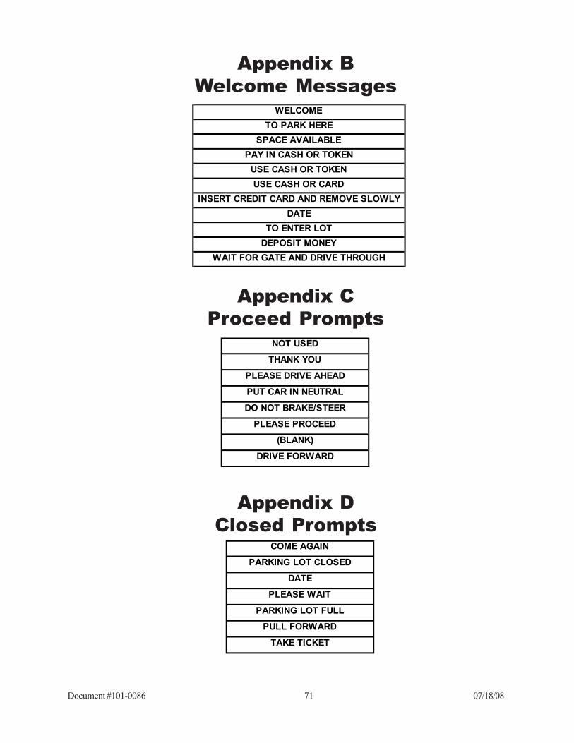
Document #101-0086 71 07/18/08
Appendix BWelcome Messages
WELCOMETO PARK HERE
SPACE AVAILABLEPAY IN CASH OR TOKEN
USE CASH OR TOKENUSE CASH OR CARD
INSERT CREDIT CARD AND REMOVE SLOWLYDATE
TO ENTER LOTDEPOSIT MONEY
WAIT FOR GATE AND DRIVE THROUGH
Appendix CProceed Prompts
NOT USED
THANK YOU
PLEASE DRIVE AHEAD
PUT CAR IN NEUTRAL
DO NOT BRAKE/STEER
PLEASE PROCEED
(BLANK)
DRIVE FORWARD
Appendix DClosed Prompts
COME AGAIN
PARKING LOT CLOSED
DATE
PLEASE WAIT
PARKING LOT FULL
PULL FORWARD
TAKE TICKET

Document #101-0086 72 07/18/08
LIMITED WARRANTY AGREEMENTOF HAMILTON MANUFACTURING CORP.
Hamilton Manufacturing Corp., an Ohio Corporation, (“Seller”) warrants to Purchaser that allnew equipment shall be free from defects in material and factory workmanship for a period of one (1)year from the original shipping date. Hamilton Manufacturing Corp. further warrants if any part of saidnew equipment in Seller’s sole opinion, requires replacement or repair due to a defect in material orfactory workmanship during said period, Seller will repair or replace said new equipment. Purchaser’sremedies and the liabilities and obligations of Seller herein shall be limited to repair or replacement ofthe equipment as Seller may choose, and Seller’s obligation to remedy such defects shall not exceedthe Purchaser’s original cost for the equipment. Purchaser EXPRESSLY AGREES this is the EXCLU-SIVE REMEDY under this warranty. There are no other express or implied warranties which extendbeyond the face hereof. All warranty repair service must be performed by either a Factory TrainedService Representative or HAMILTON MANUFACTURING CORP., 1026 Hamilton Drive, Hol-land, Ohio 43528 PHONE (419) 867-4858 or (800) 837-5561, FAX (419) 867-4867.
The limited warranty for new equipment is conditioned upon the following:
1. The subject equipment has not, in the Seller’s sole opinion, beensubjected to: accident, abuse, misuse, vandalism, civil disobedience,riots, acts of God, natural disaster, acts of war or terrorism.
2. The Seller shall not be liable for any expense incurred by Purchaserincidental to the repair or replacement of equipment and Purchasershall assume full responsibility for any freight or shipping charges.
3. The coverage of this warranty shall not extend to expendable parts.4. Purchaser shall have a warranty registration card on file with Seller
prior to any claim in order for warranty protection to apply.5. No warranty coverage is applicable to any equipment used for cur-
rency other than that specified at the time of the purchase.6. Seller expressly disclaims any warranty that counterfeit currency will
not activate said equipment.7. Seller expressly disclaims any warranty for any losses due to bill
manipulation or theft or loss of cash under any circumstances.8. Use of the equipment for anything other than its intended and designed
use will void the Limited Warranty Agreement. Use of equipment foranything other than its intended and designed use includes, but is notlimited to, downloading software/applications not certified by Sellersuch as e-mail, spyware, screen savers, viruses, worms, third partysoftware, web search engines, cookies, spam, desktop applications,games, web surfing, etc.
Seller further warrants all repair or service work performed by a factory trained representativeor Hamilton Manufacturing Corp. for a period of ninety (90) days from the date the repair or servicework was performed. Purchaser’s remedies and the liabilities and obligations of Seller herein shall belimited to repair or replacement of equipment as Seller may choose, and Seller’s obligation to remedysuch defects shall not exceed the Purchaser’s depreciated value of the equipment. Purchaser EXPRESSLYAGREES this is an EXCLUSIVE REMEDY under this warranty. There are no other express or impliedwarranties on repair or service work performed by a factory trained representative or Hamilton Manu-facturing Corp. which extend beyond the face hereof.

Document #101-0086 73 07/18/08
The limited warranty for repair and service work is conditioned upon the following:
1. The subject equipment has not, in the Seller’s sole opinion, beensubjected to: accident, abuse, misuse, vandalism, civil disobedience,riots, acts of God, natural disaster, acts of war or terrorism.
2. The Seller shall not be liable for any expense incurred by Purchaserincidental to the repair or replacement of equipment and Purchasershall assume full responsibility for any freight or shipping charges.
3. The coverage of this warranty shall not extend to expendable parts.4. Purchaser shall have a warranty registration card on file with Seller
prior to any claim in order for warranty protection to apply.5. No warranty coverage is applicable to any equipment used for cur-
rency other than that specified at the time of the purchase.6. Seller expressly disclaims any warranty that counterfeit currency will
not activate said equipment.7. Seller expressly disclaims any warranty for any losses due to bill
manipulation or theft or loss of cash under any circumstances.8. No person or entity other than a factory trained representative or
Hamilton Manufacturing Corp. has performed or attempted to performthe subject repair or service.
9. Using equipment which has been serviced or repaired for anythingother than its intended or designed use such as downloading softwareapplications not certified by Seller will void the Limited WarrantyAgreement. This includes software/applications such as e-mail,spyware, screen savers, viruses, worms, third party software, websearch engines, cookies, spam, desktop applications, games, websurfing, etc.
THIS AGREEMENT IS MADE WITH THE EXPRESS UNDERSTANDING THAT THEREARE NO IMPLIED WARRANTIES THAT THE EQUIPMENT SHALL BE MERCHANTABLE, ORTHAT THE GOODS SHALL BE FIT FOR ANY PARTICULAR PURPOSE. PURCHASER HEREBYACKNOWLEDGES THAT IT IS NOT RELYING ON THE SELLER’S SKILL OR JUDGMENT TOSELECT OR FURNISH EQUIPMENT SUITABLE FOR ANY PARTICULAR PURPOSE AND THATTHERE ARE NO WARRANTIES WHICH EXTEND BEYOND THAT WHICH IS DESCRIBEDHEREIN.
The Purchaser agrees that in no event will the Seller be liable for direct, indirect, or consequen-tial damages or for injury resulting from any defective or non-conforming new, repaired or servicedequipment, or for any loss, damage or expense of any kind, including loss of profits, business interrup-tion, loss of business information or other pecuniary loss arising in connection with this Limited War-ranty Agreement, or with the use of, or inability to use the subject equipment regardless of Sellersknowledge of the possibility of the same.

Document #101-0086 75 07/18/08
1026 Hamilton DriveHolland, OH 43528
Sales Phone: (888) 723-4858 Sales Fax: (419) 867-4850Customer Service Phone: (800) 837-5561 Customer Service Fax: (419) 867-4857
Parts Phone: (866) 835-1721 Parts Fax: (419) 867-4867Website: http://www.hamiltonmfg.com
Email Addresses:[email protected]@[email protected]
Hamilton Manufacturing Corporation