Embed Size (px)
Citation preview

Gold & Aluminum Bonding Wedges
Bonding Spectrum
1890ROTH GroupLyss, Switzerland
1964Aprova Ltd.Lyss, Switzerland
1974Small Precision Tools Inc.California, USA
1979SPT Asia Pte Ltd.Singapore
1982Moldinject, Perfectamould AG.Lyss, Switzerland
1991Small Precision Tools (Phils.) Inc.Manila, Philippines
1995Small Precision Tools Co. Ltd.Wuxi, China
2001SPT Japan Co.,Ltd.Yokohama, Japan
Pioneer . World Leader .
Small Precision Tools - SPT - is the pioneer and leader of semiconductor bonding tools for over three decades.
SPT is the only bonding tool manufacturer internationally established with marketing and production centres strategically positioned all over the globe, to
Global Vision . Worldwide Network . Local Presence .
The SPT Roth Group’s strategy centers on developing the Company into an integrated global corporation. Over the last twenty years, we have built on our global vision and invested in building manufacturing and sales facilities strategically around the world to be close to our customers.
The worldwide network combined with excellent logistic facilities ensures prompt and ful l compliance with customer requirements including ship-to-stock or just-in-time delivery programs. Dedicated and highly qualified sales and service engineers and application specialists ensure that customers receive professional service and support at all times from the design phase to starting mass production.

TechnologyEvaluation Optimization Precision ExcellenceTraining
Quality . Product & Service Excellence .
SPT is committed to quality and customer care. Our commitment to product excellence and continued support of our customers is part of the sustaining culture of SPT.
SPT’s partnership philosophy has earned numerous prest ig ious awards and
Development DesignResearch Partnership
Creative Solutions . Research & Development . Customer Partnership .
Customer partnership is our belief. At SPT, we listen to our customers. Because, every customer’s needs are different, every solution is uniquely designed to satisfy those needs in the most effective way.
SPT offers a wide range of proactive support and services such as consulting, design, analysis, training seminars and benchmarking partnerships. SPT’s material and process technology laboratories in Switzerland and Singapore offer technical support and services such as

Die Attach Collets Bushings Precision PartsWaffle Tab Tool CIM & MIM Parts Watch GearBonding Capillary µBGA Tab Tool Fine Pitch Bonding Wedge
Product Technology . Excellence . Unsurpassed .
SPT positions itself as a progressive high-technology tool manufacturer using state-of-the art processes. Our production capabilities range from conventional to CNC machining including milling, turning, surface grinding, honing, Electro-Discharge Machining or EDM, jig grinding and more. Our exclusive Injection Molding technology of small complex parts through SPT’s own in-house formulation and sintering assures customers of the highest quality in high alumina ceramic and carbide materials.
Our equipment and manufactur ing techniques are the most advanced in the ultra precision tool industry.
We make standard and custom designs for specific customer requirements. All

The most commonly used method of connecting semiconductor devices to the ‘outside’ world is via gold or aluminum wire, ranging from .0005”/13µm to .003”/76µm for Au wire and .0008”/20µm to .020”/508µm for Al wire. The tip of the wedge vibrates parallel to the bonding wire. The weld is created by deforming the wire at a low temperature in which the energy for the weld formation is supplied from an ultrasonic transducer vibrating (60 to 120 kHz) the bonding tool or wedge. Aluminum wires are connected ultrasonically, gold wires using thermosonic welding (combination of heat 150° - 250°C and ultrasonic energy).
Wedge Bonding is a perennial technology for a niche market. In the early years of semiconductor, wedge bonding is commonly being used as a method of interconnection for Semiconductor Devices, Diode and single Transistor. At present, wedge bonding is popular for COB, Discrete, Hybrid, Hermetic and High Power Devices. With the many benefits that wedge bonding can offer such as deep access, fine pitch, and low and short loops bonding, it became a well known technique that is extensively being used in microwave and optoelectronics applications.
The low temperature wedge bonding is also attractive for some applications like Flex circuits as this helps prevent the softening of adhesive layers on the flex. Softened flex will absorb more of the ultrasonic energy during bonding resulting to poor bond reliability.
Ultrasonic wedge bonding (SM & LW wire).
1
TEChNoLoGy oVERViEW
iNTR
oD
UC
Tio
N
introduction1 Technology Overview
The Wedge Bonding Process2 Basic Ultrasonic Wedge Bonding Process4 Available Materials6 Wire Bonding Guide6 Destructive bond pull test7 Non-destructive bond pull test8 Bonding Failures
Small Wire Bonding Tools10 Fine Pitch Bonding Tool ................................ FP12 Universal Bonding Tool ................................. US / UT 14 Chip-On-Board Autobonding Tool ................. UT16 Autobonding Tool .......................................... ABT18 Microwave Bonding Tools ............................. M30A / M45A / M55A / M60A /
M30B / M45B / M55B / M60B20 Standard Notch Bonding Tools ...................... 1001A / 1002A / 1110A /
1001B / 1002B / 1110B 22 Slimline Notch Bonding Tools ........................ 1200A / 1300A / 1400A / 1100A /
1200B / 1300B / 1400B / 1100B 24 Special Bonding Tools ................................... 1008A26 Special Bonding Tools ................................... XGR28 PF Needles ................................................... PF2030 Ribbon Wire Bonding Tools ........................... RW30 / RW45 / RW55 / RW60
Large Wire Bonding Tools32 Large Wire Bonding34 Inline Groove No-hole Bonding Tools ............ oSG7 36 Inline Groove No-hole Bonding Tools ............ CKVD 38 Inline Groove No-hole Bonding Tools ............ CK40 Inline Groove Bonding Tools ......................... 45CK 42 Inline Groove No-hole Bonding Tools ............ LWD6 44 Concave No-hole Bonding Tools ................... 1009A46 Inline Groove Notch Tools ............................. 3016 / 451648 Inline Groove Notch Tools ............................. 1015A / 1016A / 2015A / 2016A 50 Inline Groove Notch Tools ............................. 30D6 / 45D6 / 60D6 52 Inline Groove Autobonding Tools .................. AB16
Single Point Tab Bonding Tools54 Single Point Tab Bonding Tools56 Double Cross Groove ................................... 7000 / 7100 58 Double Cross Protrusion ............................... 7500 / 7600 60 Waffle Foot .................................................... 7045W / 7145W 62 Waffle Foot – Shank Flats ............................. 7045W / 7145W
Small / Large Wire Shank Styles63 Small Wire Shank Style………………….. ..... V Style / J Style / h Style / P Style /
Standard Style / 180Deg-Rev 64 Large Wire Shank Style65 Tip to Shank Ratios
66 Tool Selection Guide
69 Wedges Requirement Checklist
All dimensions are in inch/µm unless otherwise stated.We reserve the right to make changes to design or specifications at any time without notice.
CoNTENTS
The Wire Bonding Process
Small Wire Bonding Tools
Large Wire Bonding Tools
Single Point Tab Bonding Tools
Small / Large Wire Shank Styles
2 3
Wedge bonding technique can be used for both aluminum wire and gold wire bonding applications with some slight modification to the back radius to compensate for the lower tensile strength of gold wire. The principle difference between the two processes is that the aluminum wire is bonded in an ultrasonic bonding process at room temperature, whereas gold wire wedge bonding is performed through a thermosonic bonding process with heat up to 175°C. A considerable advantage of the wedge bonding is that it can be designed and manufactured to very small dimensions, down to 50µm pitch. Aluminum ultrasonic bonding is the most common wedge bonding process because of the low cost and can be bonded at room temperature. The main advantage for gold wire wedge bonding is the possibility of avoiding the need for hermetic packaging after bonding due to the inert properties of the gold. In addition, a wedge bond will give a smaller footprint than a ball bond, which specially benefits the microwave devices with small pads that require a gold wire junction down to .0005”/ 13µm.
BoNDiNG WEDGE TooLS
Wedge bonding is performed using a wedge-shaped bonding tool. The wire in wedge bonding is addressed at an angle (30o to 60o) through the rear of the wedge. When special clearance is necessary the wire will be fed at 90° through a hole in the shank for maximum clearance. Low angle wire feed style gives best placement control and tail consistency under the bond foot. High angle wire feed is only used when absolutely necessary due to high package walls where the bonding to the edge of the die is necessary. Tail control and bond placement accuracy is less consistent due to the steep feed angle which causes the wire tail to contact the pad prematurely causing the wire to shift away from underneath the bonding tip or be pushed back into the feed hole. Unlike at lower feed angles (30° to 45°) the wire is in line with the tip. Foot profile of the wedge can be either flat or concave. Most of the automatic aluminum wire applications use the concave foot to reduce wire positioning errors. The flat foot is used mainly with gold wire or with aluminum wire to obtain extremely short bonds. A groove foot has been designed for gold wire wedge bonding to improve the wedge-to-wire gripping. The material used for the wedge is dependent on the bonding wire material. For aluminum wire, the wedge is made of tungsten carbide. For gold wire, the material used is titanium carbide or cermet tip. The cermet tip wedge is most commonly used in applications where low temperature Au to Au bonding is required.
The parameters of the wedge can greatly affect the wire-bond characteristics. For the first bond, pull strength is affected by back radius (BR), bond location is influenced by hole size (H) and tail length is controlled by feed angle, hole shape and surface quality. The main wedge parameters that affect looping are hole size and shape, as well as feed angle. For the second bond, pull strength is defined mainly by front radius (FR), bond length and tail consistency is affected by back radius (BR).
BASiC ULTRASoNiC WEDGE BoNDiNG PRoCESS
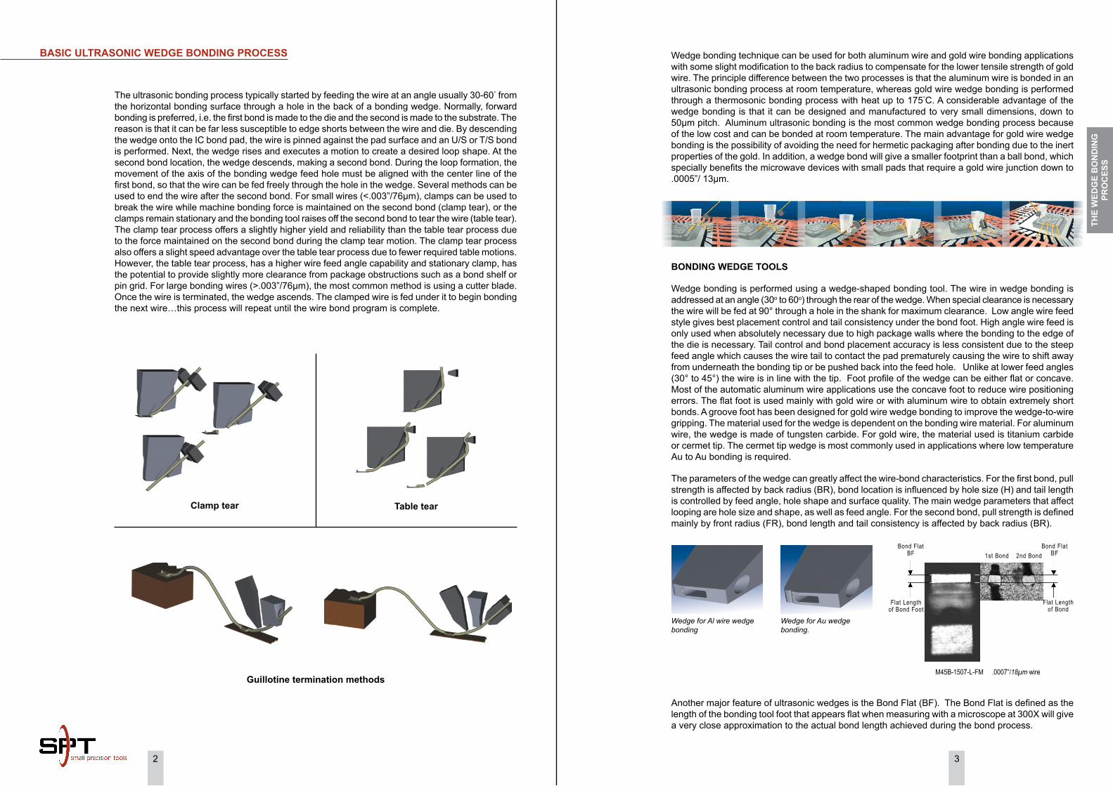
Clamp tear
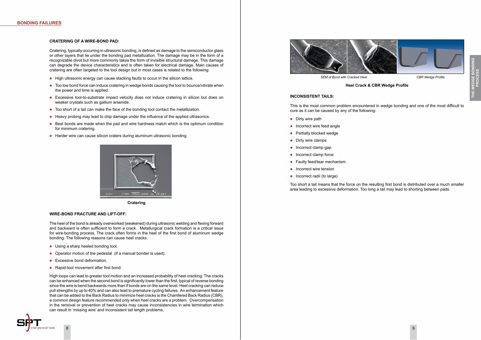
Another major feature of ultrasonic wedges is the Bond Flat (BF). The Bond Flat is defined as the length of the bonding tool foot that appears flat when measuring with a microscope at 300X will give a very close approximation to the actual bond length achieved during the bond process.
Wedge for Al wire wedge bonding
Wedge for Au wedge bonding.
Guillotine termination methods
Table tear
The ultrasonic bonding process typically started by feeding the wire at an angle usually 30-60° from the horizontal bonding surface through a hole in the back of a bonding wedge. Normally, forward bonding is preferred, i.e. the first bond is made to the die and the second is made to the substrate. The reason is that it can be far less susceptible to edge shorts between the wire and die. By descending the wedge onto the IC bond pad, the wire is pinned against the pad surface and an U/S or T/S bond is performed. Next, the wedge rises and executes a motion to create a desired loop shape. At the second bond location, the wedge descends, making a second bond. During the loop formation, the movement of the axis of the bonding wedge feed hole must be aligned with the center line of the first bond, so that the wire can be fed freely through the hole in the wedge. Several methods can be used to end the wire after the second bond. For small wires (<.003”/76µm), clamps can be used to break the wire while machine bonding force is maintained on the second bond (clamp tear), or the clamps remain stationary and the bonding tool raises off the second bond to tear the wire (table tear). The clamp tear process offers a slightly higher yield and reliability than the table tear process due to the force maintained on the second bond during the clamp tear motion. The clamp tear process also offers a slight speed advantage over the table tear process due to fewer required table motions. However, the table tear process, has a higher wire feed angle capability and stationary clamp, has the potential to provide slightly more clearance from package obstructions such as a bond shelf or pin grid. For large bonding wires (>.003”/76µm), the most common method is using a cutter blade. Once the wire is terminated, the wedge ascends. The clamped wire is fed under it to begin bonding the next wire…this process will repeat until the wire bond program is complete.
Bond Flat BF
Flat Lengthof Bond Foot
Bond Flat BF
Flat Lengthof Bond
1st Bond 2nd Bond
M45B-1507-L-FM .0007”/18µm wire
ThE
WED
GE
Bo
ND
iNG
PR
oC
ESS

4 5
AVAiLABLE MATERiALS
Microloy (M) is the material of choice for all types of difficult to bond applications. This material has the coupling advantages of Cermet with the added advantages of reduced build-up and it can be used with Aluminum, Gold and Platinum wire and ribbon. Microloy can be used to bond any type of bondable wire to any type of bondable substrate or die. This unique material is only available from SPT and its applications and advantages include:
LoNGER TooL LiFE
Typically,customers find the tool life several times longer because of wear-resistant osmium alloy at the tip of our tools. The consistency of Microloy makes the tool lifetime predictable and stable for a given application.
“LoW STRESS” BoNDiNG
Because of the excellent ultrasonic coupling, many users of Microloy tools find that they can bond with less power, force, time and/or temperature, including room temperature bonding of gold wire at 60k Hz.
hiGhER RELiABiLiTy BoNDS
The unique finishes possible with Microloy enhance the transmission of ultrasonic energy and improve the quality of the bond, especially with gold interconnects.
FiNE PiTCh BoNDiNG WEDGES
The Microloy bonding tools are being used in a 35 micron pitch bonding process.
Microloy’s properties plus our state-of-the-art manufacturing expertise allow a unique bonding surface finish for efficient ultrasonic coupling, with minimal build-up for longer tool life.
High and consistent pull strength.
Reduced bond power, force and time.
Less deformation of bond.
Eliminate cross-grooves.
Wedge Bonding Tool Surface Matte “M” Frost “F”
Tungsten Carbide (W) is widely used because of its extraordinary properties and is particularly suited for a variety of wear resistant tools.Tungsten Carbide is the most commonly used material for Aluminum wire and ribbon bonding. Our premium grade Tungsten Carbide provides efficient ultrasonic energy transfer due to its uniform, high density, fine grain structure.
SPT premium grade fine grain Tungsten Carbide Material
Tungsten Carbide from another supplier
Titanium Carbide (Ti) ) is the typical choice for gold wire and ribbon bonding applications. Titanium Carbide is a sintered alloy of Titanium and various binders. Our material is an industry recognized standard for gold wedge bonding. SPT supplies high quality Ti Carbide tools for standard bonding applications and fine pitch wedge and ribbon bond tools with high structural integrity.
Cermet (C) is an optional material for gold wire, ribbon and TAB applications at lower bonding temperatures. The naturally coarse texture of our ceramic-metal alloy “Cermet” provides enhanced ultrasonic coupling, allowing reduced bonding parameters, gentler touchdown and extended tool life. All Cermet bonding tools are manufactured using a two piece construction. SPT’s proprietary brazing technique creates a uniform, ultra thin brazed joint with our Tungsten Carbide shank, allowing seamless ultrasonic transfer equivalent to a unibody carbide wedge.
Microloy (M) is the latest addition to the SPT bonding tool product line. In the 1970’s, Microminiature Technology, Inc. discovered that an Osmium (Os) based carbide alloy had a set of properties that made it an ideal material for the tips of bonding tools used in ultrasonic wire, ribbon and TAB bonding. Its wear-resistance and unique surface finishes allow for unparalleled ultrasonic coupling. The alloy was given the name “Microloy”, and its critical properties include: High density.
High elastic modulus.
Extreme hardness.
Excellent wear resistance.
Fine grain structure.
Low porosity.
ThE
WED
GE
Bo
ND
iNG
PR
oC
ESS

6 7
WiRE-BoNDiNG GUiDELiNE
FAiLURE MEChANiSMS oF WiRE-BoNDS:
A major advantage of wire-bonding for microelectronic interconnection is its solid base of reliability from bond strength studies to time and temperature design factors. Many factors may degrade yield and reliability of the wire-bonds. Trouble shooting can be carried out using a “fishbone diagram” to isolate the errors in wire-bonding process. It is then possible to focus problem-solving effort on fewer aspects of the process.
Schematic of non-destructive pull test
The failure during pull test may occur at one of the five positions in the wire-bond structure:
A. Lift off first bond
B. Wire break at transition first bond
C. Wire break mid span
D. Wire break at transition second bond
E. Lift off second bond
When the process is in control, the bond should fail at B or D. If failures occur at A, C, or E, then the bonding parameters, metallization, bonding machine, bonding tool, bonding wire and wire pull hook all have to be reviewed.
Non-Destructive Bond Pull Test:
This test is a variation of the destructive pull test in that the maximum force applied to the bond loop is limited to a predetermined value. It is usually used to detect unacceptable wire-bonds while avoiding damage to acceptable wire-bonds. The most common failures are bond lifts, tight wires, heel cracks and cratering. The non-destructive pull test force is specified for a given wire diameter and metallurgy.
PRoCESS DEVELoPMENT AND oPTiMizATioN:
The key stages generally include initial process design and development, process characterization, process control and process optimization. These stages form a continuous loop between characterization and control with periodic optimization and development.
In the initial stages of the process, process capabilities should be known to set achievable goals. The second stage (process characterization) is to collect and categorize the data on wire-bonding failures such as bond off center, bond not sticking on die, wire breaking and so on. Process control (the third stage) is important for a successful process. To achieve a stable performance, the operating variables such as bond program parameters, machine setup, operation procedures, bonding tool installation, wire pull procedures and product change must be minimized and consistent across the process, such as in the training of operators must be established. If the previous stages of process development are in place, process optimization can be performed. Once a process is operating in a production environment, statistical process control (SPC) can be applied to such items as destructive wire pull and non-destructive wire pull (commonly used in military products and large wire-bonding applications) to monitor the process and to minimize process drift.
BoND EVALUATioN:
After bonding, the wire-bond can be evaluated with visual and mechanical testing. Depending on the customer requirements, the following are the three most common mechanical testing methods that are employed for the evaluation of bond strength.
1. Destructive bond pull test
2. Non-destructive bond pull test (most commonly used in military and automotive products)
3. Bond shear test (commonly used in wire dia. >.004”/100µm)
Destructive Bond Pull Test:
Destructive pull test, i.e. bond pull strength test, is the primary method to evaluate the bond strength by hooking and pulling the bonded wire until failure occurs. The purpose of this test is to examine the bond strength and to certify the proper setup of the bonding machine parameters. The results are important evidences for evaluating bonding quality and reliability. The same results evaluate the understanding of bond failure mechanisms including bond pad cratering, over-bonding and shear fatigue at bonded interfaces during temperature cycling. Pull strength is strongly dependent upon the geometrical configuration of the pull test.
Schematic of destructive pull test
ThE
WED
GE
Bo
ND
iNG
PR
oC
ESS
8 9
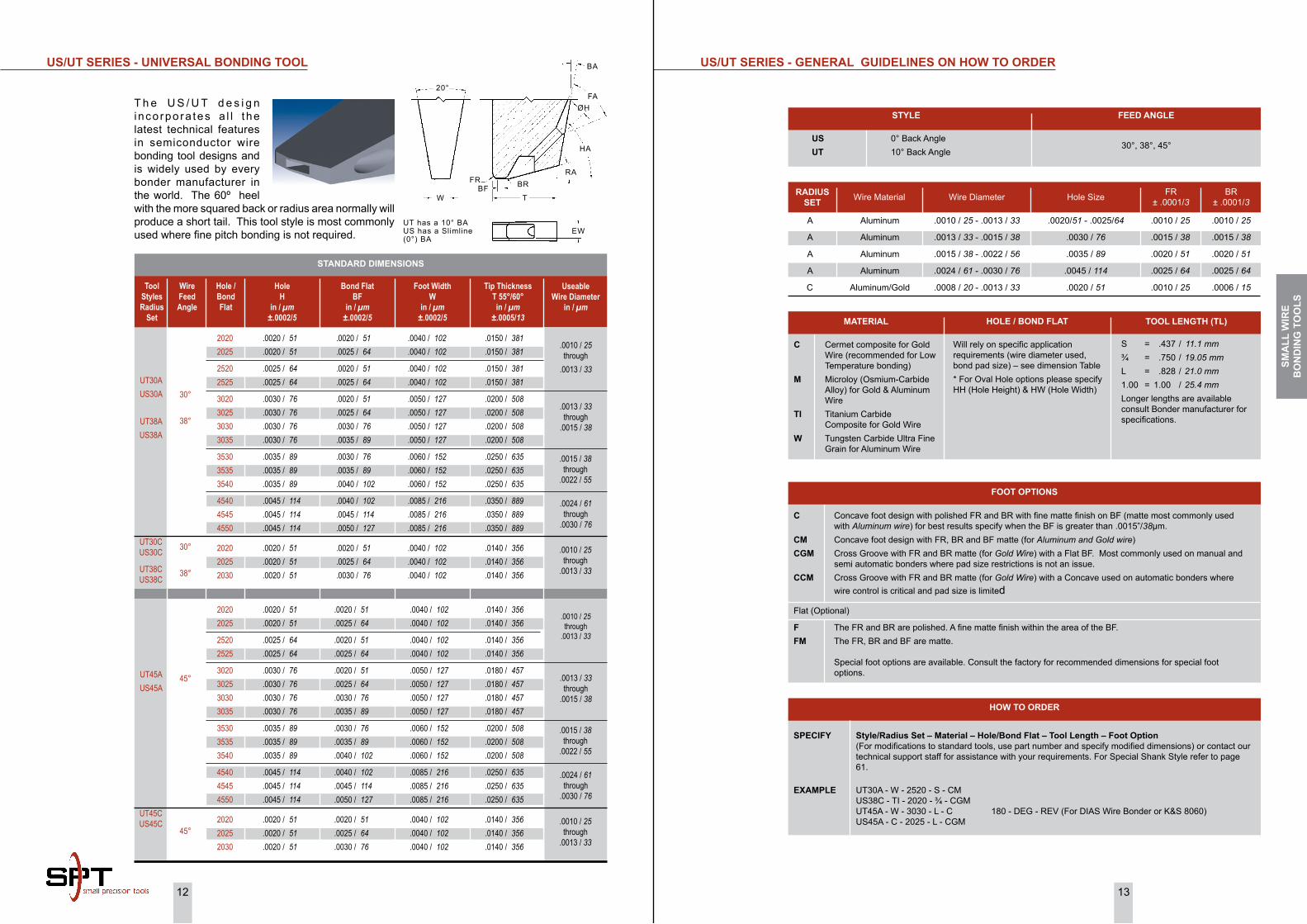
Heel Crack & CBR Wedge Profile
iNCoNSiSTENT TAiLS:
This is the most common problem encountered in wedge bonding and one of the most difficult to cure as it can be caused by any of the following:
Dirty wire path
Incorrect wire feed angle
Partially blocked wedge
Dirty wire clamps
Incorrect clamp gap
Incorrect clamp force
Faulty feed/tear mechanism
Incorrect wire tension
Incorrect radii (to large)
Too short a tail means that the force on the resulting first bond is distributed over a much smaller area leading to excessive deformation. Too long a tail may lead to shorting between pads.
BoNDiNG FAiLURES
CRATERiNG oF A WiRE-BoND PAD:
Cratering, typically occurring in ultrasonic bonding, is defined as damage to the semiconductor glass or other layers that lie under the bonding pad metallization. The damage may be in the form of a recognizable divot but more commonly takes the form of invisible structural damage. This damage can degrade the device characteristics and is often taken for electrical damage. Main causes of cratering are often targeted to the tool design but in most cases is related to the following:
High ultrasonic energy can cause stacking faults to occur in the silicon lattice.
Too low bond force can induce cratering in wedge bonds causing the tool to bounce/vibrate when the power and time is applied.
Excessive tool-to-substrate impact velocity does not induce cratering in silicon but does on weaker crystals such as gallium arsenide.
Too short of a tail can make the face of the bonding tool contact the metallization.
Heavy probing may lead to chip damage under the influence of the applied ultrasonics.
Best bonds are made when the pad and wire hardness match which is the optimum condition for minimum cratering.
Harder wire can cause silicon craters during aluminum ultrasonic bonding.
WiRE-BoND FRACTURE AND LiFT-oFF:
The heel of the bond is already overworked (weakened) during ultrasonic welding and flexing forward and backward is often sufficient to form a crack. Metallurgical crack formation is a critical issue for wire-bonding process. The crack often forms in the heel of the first bond of aluminum wedge bonding. The following reasons can cause heel cracks:
Using a sharp heeled bonding tool.
Operator motion of the pedestal (if a manual bonder is used).
Excessive bond deformation.
Rapid-tool movement after first bond.
High loops can lead to greater tool motion and an increased probability of heel cracking. The cracks can be enhanced when the second bond is significantly lower than the first, typical of reverse bonding since the wire is bend backwards more than if bonds are on the same level. Heel cracking can reduce pull strengths by up to 40% and can also lead to premature cycling failures. An enhancement feature that can be added to the Back Radius to minimize heel cracks is the Chamfered Back Radius (CBR), a common design feature recommended only when heel cracks are a problem. Overcompensation in the removal or prevention of heel cracks may cause inconsistencies in wire termination which can result in ‘missing wire’ and inconsistent tail length problems.
SEM of Bond with Cracked Heel CBR Wedge Profile
Cratering
ThE
WED
GE
Bo
ND
iNG
PR
oC
ESS

10 11
STANDARD DIMENSIONS
FP SERiES - GENERAL GUiDELiNES oN hoW To oRDER
STyLE FEED ANGLE
FP = Fine Pitch Standard Design 30°, 38°, 45°, 55°, 60°
RADiUS SET Wire Material Wire Diameter Hole Size FR
± .0001/3BR
± .0001/3
A
B
B
C
Aluminum / Gold
Gold
Aluminum
Gold
.0010 / 25 - .0015 / 38
.0010 / 25 - .0015 / 38
.0007 / 18 - .0010 / 25
.0005 / 13 - .0010 / 25
.0015 / 38 - .0030 / 76
.0015 / 38 - .0030 / 76
.0015 / 38 - .0020 / 51
.0015 / 38 - .0020 / 51
.0010 / 25
.0010 / 25
.0010 / 25
.0004 / 10
.0010 / 25
.0006 / 15
.0006 / 15
.0004 / 10
C Cermet composite for Gold Wire (recommended for Low Temperature bonding)
M Microloy (Osmium-Carbide Alloy) for Gold & Aluminum Wire
Ti Titanium Carbide Composite for Gold Wire
W Tungsten Carbide Ultra Fine Grain for Aluminum Wire
Will rely on specific application requirements (wire diameter used, bond pad size) – see dimension Table* For Oval Hole options please specify HH (Hole Height) & HW (Hole Width)
S = .437 / 11.1 mm¾ = .750 / 19.05 mmL = .828 / 21.0 mm1.00 = 1.00 / 25.4 mmLonger lengths are available consult Bonder manufacturer for specifications.
MATERiAL hoLE / BoND FLAT TooL LENGTh (TL)
C Concave foot design with polished FR and BR with fine matte finish on BF (matte most commonly used with Aluminum wire) for best results specify when the BF is greater than .0015”/38µm.
CM Concave foot design with FR, BR and BF matte (for Aluminum and Gold wire)
Flat (Optional)
FM Flat foot design FR, BR and BF are matte (for Gold Wire) or wire diameter less than .0013”/33µm and BF is less than .0015”/38µm
CGM Cross Groove with FR and BR matte (for Gold Wire) with a matte Flat BF. Most commonly used on manual and semi automatic bonders where pad size restrictions is not an issue. Not recommended for BF smaller than .0020”/50µm
CCM Cross Groove with FR and BR matte (for Gold Wire) with a matte Concave BF. Most commonly used on automatic bonders where wire control is critical and pad size is limited. Not recommended for BF smaller than .0020”/50µm
FooT oPTioNS
SPECiFy Style/Radius Set – Material – hole/Bond Flat – Tool Length – Foot option (For Fine Pitch application below 80µm BPP, refer to page 8 for VR sets to specify, otherwise specify VR and VW) or contact our technical support staff for assistance with your requirements. For Special Shank Style refer to page 61.
EXAMPLE FP45A - W - 2020 - L - CM 180 - DEG - REV FP38B - TI - 1515 - ¾ - FM VR = Set B FP60B - C - 2025 - L - CGM VR = Set A FP55B-TI-1520-3/4-CGM HH = .0020 HW=.0015 VR Set C
hoW To oRDER
There are a number of technical challenges unique to fine pitch wire-bond process. It includes a broad mix of component technologies. A typical package may contain 200 different components ranging in size from (.008 inch X .008 inch) and .004 inches thick to (.500 inch X .500 inch). The sheer number of different sized chips and tight chip-to-chip spacing create problems in accessing the bond pads. Fine pitch wire-bonding is of particular importance in the manufacturing of these devices. Fine pitch is defined as 100 microns or less center-to-center distances between bond pads. Many devices use the latest high performance chips that typically include 4 mil pitch bond pads. Innovations in tool configurations, machine vision systems and wire-bonding ultrasonics have been critical to improved fine pitch wedge bonding
Tip Thickness T 55°/60°in / µm
±.0005/13
Tip Thickness T 38°/45°in / µm
±.0005/13
Tip Thickness T 30°
in / µm±.0005/13
Foot WidthW
in / µm±.0002/5
Bond Flat BF
in / µm±.00015/3.8
UseableWire Diameter
in / µm
.0120 / 305 .0120 / 305 .0120 / 305 .0120 / 305
.0120 / 305 .0120 / 305 .0120 / 305
.0120 / 305 .0140 / 356 .0140 / 356 .0140 / 356
.0170 / 432 .0170 / 432
.0170 / 432
HoleH
in / µm±.00015/3.8
Hole / Bond Flat
.0140 / 356 .0140 / 356 .0140 / 356 .0140 / 356
.0140 / 356 .0140 / 356 .0140 / 356
.0140 / 356 .0140 / 356 .0140 / 356 .0140 / 356
.0190 / 483 .0190 / 483 .0190 / 483
.0140 / 356 .0140 / 356 .0140 / 356 .0140 / 356
.0150 / 381 .0150 / 381 .0150 / 381
.0190 / 483 .0190 / 483 .0190 / 483 .0190 / 483
.0200 / 508 .0200 / 508 .0200 / 508
.0030 / 76 .0030 / 76 .0030 / 76 .0030 / 76
.0030 / 76 .0030 / 76 .0030 / 76
.0030 / 76 .0040 / 102 .0040 / 102 .0040 / 102
.0040 / 102 .0040 / 102 .0040 / 102
.0007 / 18 .0010 / 25 .0015 / 38 .0020 / 51
.0010 / 25 .0015 / 38 .0020 / 51
.0025 / 64 .0020 / 51 .0025 / 64 .0030 / 76
.0025 / 64 .0030 / 76 .0035 / 89
.0015 / 38 .0015 / 38 .0015 / 38 .0015 / 38
.0020 / 51 .0020 / 51 .0020 / 51
.0020 / 51 .0025 / 64 .0025 / 64 .0025 / 64
.0030 / 76 .0030 / 76 .0030 / 76
150715101515 1520
2010 20152020
2025252025252530
302530303035
30°
38°
45°
55°
60°
FP30
FP38
FP45
FP55
FP60
.0005 / 13 through
.0008 / 20
.0008 / 20through
.0010 / 25
.0010 / 25through
.0013 / 33
.0015 / 38through
.0020 / 51
Wire Feed Angle
Tool Styles
FP SERiES - FiNE PiTCh BoNDiNG TooL
20°
VR
WFR BR
BF
30°, 38°, 45°
ØH
45°
Vertical Relief “VR” supplied as needed depending on Bond Pad Pitch
T
30°ØH
55°, 60°
20°10°FR BR
BFT
WD
WVW
VR
VR Set “A” 70µm to 80µm BPP W = .0030”, VW = .0040”, VR = .0060”
VR Set “B” 60µm to 70µm BPP W = .0025”, VW = .0030”, VR = .0060”
VR Set “C” 50µm to 60µm BPP W = .0020”, VW = .0025”, VR = .0060”Max HW = .0015”, for WD = .0010” or lessOval Hole
SMA
LL W
iRE
Bo
ND
iNG
To
oLS
12 13
A
A
A
A
C
Aluminum
Aluminum
Aluminum
Aluminum
Aluminum/Gold
.0010 / 25 - .0013 / 33
.0013 / 33 - .0015 / 38
.0015 / 38 - .0022 / 56
.0024 / 61 - .0030 / 76
.0008 / 20 - .0013 / 33
.0020/51 - .0025/64
.0030 / 76
.0035 / 89
.0045 / 114
.0020 / 51
.0010 / 25
.0015 / 38
.0020 / 51
.0025 / 64
.0010 / 25
.0010 / 25
.0015 / 38
.0020 / 51
.0025 / 64
.0006 / 15
UT30C US30C
UT38C US38C
30°
38°
STANDARD DiMENSioNS
US/UT SERiES - GENERAL GUiDELiNES oN hoW To oRDER
C Concave foot design with polished FR and BR with fine matte finish on BF (matte most commonly used with Aluminum wire) for best results specify when the BF is greater than .0015”/38µm.
CM Concave foot design with FR, BR and BF matte (for Aluminum and Gold wire)CGM Cross Groove with FR and BR matte (for Gold Wire) with a Flat BF. Most commonly used on manual and
semi automatic bonders where pad size restrictions is not an issue.CCM Cross Groove with FR and BR matte (for Gold Wire) with a Concave used on automatic bonders where
wire control is critical and pad size is limited
Flat (Optional)
F The FR and BR are polished. A fine matte finish within the area of the BF.FM The FR, BR and BF are matte.
Special foot options are available. Consult the factory for recommended dimensions for special foot options.
FooT oPTioNS
SPECiFy Style/Radius Set – Material – hole/Bond Flat – Tool Length – Foot option (For modifications to standard tools, use part number and specify modified dimensions) or contact our technical support staff for assistance with your requirements. For Special Shank Style refer to page 61.
EXAMPLE UT30A - W - 2520 - S - CM US38C - TI - 2020 - ¾ - CGM UT45A - W - 3030 - L - C 180 - DEG - REV (For DIAS Wire Bonder or K&S 8060) US45A - C - 2025 - L - CGM
hoW To oRDER
C Cermet composite for Gold Wire (recommended for Low Temperature bonding)
M Microloy (Osmium-Carbide Alloy) for Gold & Aluminum Wire
Ti Titanium Carbide Composite for Gold Wire
W Tungsten Carbide Ultra Fine Grain for Aluminum Wire
Will rely on specific application requirements (wire diameter used, bond pad size) – see dimension Table* For Oval Hole options please specify HH (Hole Height) & HW (Hole Width)
S = .437 / 11.1 mm¾ = .750 / 19.05 mmL = .828 / 21.0 mm1.00 = 1.00 / 25.4 mmLonger lengths are available consult Bonder manufacturer for specifications.
MATERiAL hoLE / BoND FLAT TooL LENGTh (TL)
RADiUS SET Wire Material Wire Diameter Hole Size FR
± .0001/3BR
± .0001/3
STyLE
US 0° Back AngleUT 10° Back Angle
FEED ANGLE
30°, 38°, 45°
US/UT SERiES - UNiVERSAL BoNDiNG TooL
T h e U S / U T d e s i g n i nco rpo ra tes a l l t he latest technical features in semiconductor wire bonding tool designs and is widely used by every bonder manufacturer in the world. The 60º heel with the more squared back or radius area normally will produce a short tail. This tool style is most commonly used where fine pitch bonding is not required.
Tip Thickness T 55°/60°in / µm
±.0005/13
Foot WidthW
in / µm±.0002/5
Bond Flat BF
in / µm±.0002/5
UseableWire Diameter
in / µm
HoleH
in / µm±.0002/5
Hole / Bond Flat
30°
38°
UT30AUS30A
UT38AUS38A
Wire Feed Angle
Tool StylesRadius
Set
.0150 / 381 .0150 / 381
.0150 / 381 .0150 / 381
.0200 / 508 .0200 / 508 .0200 / 508 .0200 / 508
.0250 / 635 .0250 / 635 .0250 / 635
.0350 / 889 .0350 / 889 .0350 / 889
.0140 / 356 .0140 / 356 .0140 / 356
.0040 / 102 .0040 / 102
.0040 / 102 .0040 / 102
.0050 / 127 .0050 / 127 .0050 / 127 .0050 / 127
.0060 / 152 .0060 / 152 .0060 / 152
.0085 / 216 .0085 / 216 .0085 / 216
.0040 / 102 .0040 / 102 .0040 / 102
.0020 / 51 .0025 / 64
.0020 / 51 .0025 / 64
.0020 / 51 .0025 / 64 .0030 / 76 .0035 / 89
.0030 / 76 .0035 / 89 .0040 / 102
.0040 / 102 .0045 / 114 .0050 / 127
.0020 / 51 .0025 / 64 .0030 / 76
.0020 / 51 .0020 / 51
.0025 / 64 .0025 / 64
.0030 / 76 .0030 / 76 .0030 / 76 .0030 / 76
.0035 / 89 .0035 / 89 .0035 / 89
.0045 / 114 .0045 / 114 .0045 / 114
.0020 / 51 .0020 / 51 .0020 / 51
20202025
25202525
3020 3025 3030 3035
3530 3535 3540
454045454550
20202025 2030
.0010 / 25 through
.0013 / 33
.0013 / 33 through
.0015 / 38
.0015 / 38 through
.0022 / 55
.0024 / 61 through
.0030 / 76
.0010 / 25 through
.0013 / 33
.0140 / 356 .0140 / 356
.0140 / 356 .0140 / 356
.0180 / 457 .0180 / 457 .0180 / 457 .0180 / 457
.0200 / 508 .0200 / 508 .0200 / 508
.0250 / 635 .0250 / 635 .0250 / 635
.0140 / 356 .0140 / 356 .0140 / 356
.0040 / 102 .0040 / 102
.0040 / 102 .0040 / 102
.0050 / 127 .0050 / 127 .0050 / 127 .0050 / 127
.0060 / 152 .0060 / 152 .0060 / 152
.0085 / 216 .0085 / 216 .0085 / 216
.0040 / 102 .0040 / 102 .0040 / 102
.0020 / 51 .0025 / 64
.0020 / 51 .0025 / 64
.0020 / 51 .0025 / 64 .0030 / 76 .0035 / 89
.0030 / 76 .0035 / 89 .0040 / 102
.0040 / 102 .0045 / 114 .0050 / 127
.0020 / 51 .0025 / 64 .0030 / 76
.0020 / 51 .0020 / 51
.0025 / 64 .0025 / 64
.0030 / 76 .0030 / 76 .0030 / 76 .0030 / 76
.0035 / 89 .0035 / 89 .0035 / 89
.0045 / 114 .0045 / 114 .0045 / 114
.0020 / 51 .0020 / 51 .0020 / 51
2020 2025
2520 2525
3020 3025 3030 3035
3530 3535 3540
4540 4545 4550
2020 2025 2030
45°UT45AUS45A
.0010 / 25 through
.0013 / 33
.0013 / 33 through
.0015 / 38
.0015 / 38 through
.0022 / 55
.0024 / 61 through
.0030 / 76
.0010 / 25 through
.0013 / 33
UT45C US45C
45°
UT has a 10° BAUS has a Slimline (0°) BA
BA
FA
HA
ØH
RABR
TBF
FR
W
20°
EW
SMA
LL W
iRE
Bo
ND
iNG
To
oLS
14 15
CoB SERiES - GENERAL GUiDELiNES oN hoW To oRDER
STyLE
UT UNIVERSAL BONDING TOOL
FEED ANGLE
30°
hoW To oRDER
STANDARD DIMENSIONS
Tool Styles UseableWire
Diameterin / µm
Bond Flat BF
in / µm±.0002/5
HoleH
in / µm±.0002/5
Hole / Bond Flat
Wire Feed Angle
Foot WidthW
in / µm±.0002/5
Tip Thickness
Tin / µm
±.0005/13
RADiUS SET Wire Material Wire Diameter Hole Size FR
± .0001/3BR
± .0001/3
A
A
Aluminum
Aluminum
.0010 / 25 - .0013 / 33
.0013 / 33 - .0015 / 38
.0020/51 - .0025/64
.0030 / 76
.0010 / 25
.0015 / 38
.0010 / 25
.0015 / 38
W Tungsten Carbide Ultra Fine Grain for Aluminum Wire
Will rely on specific application requirements (wire diameter used, bond pad size) – see dimension Table
S = .437 / 11.1 mm¾ = .750 / 19.05 mmL = .828 / 21.0 mm1.00 = 1.00 / 25.4 mmLonger lengths are available consult Bonder manufacturer for specifications.
MATERiAL hoLE / BoND FLAT TooL LENGTh (TL)
CM Concave foot design with FR, BR and BF matte (for Aluminum and Gold wire)
FooT oPTioNS
SPECiFy Style/Radius Set – Material – hole/Bond Flat – Tool Length – Foot option (For modifications to standard tools, use part number and specify modified dimensions) or contact our technical support staff for assistance with your requirements. For Special Shank Style refer to page 61.
EXAMPLE UT30A - 2520 - L UT30A - 2020 - ¾
CoB SERiES - ChiP-oN-BoARD AUToBoNDiNG TooL
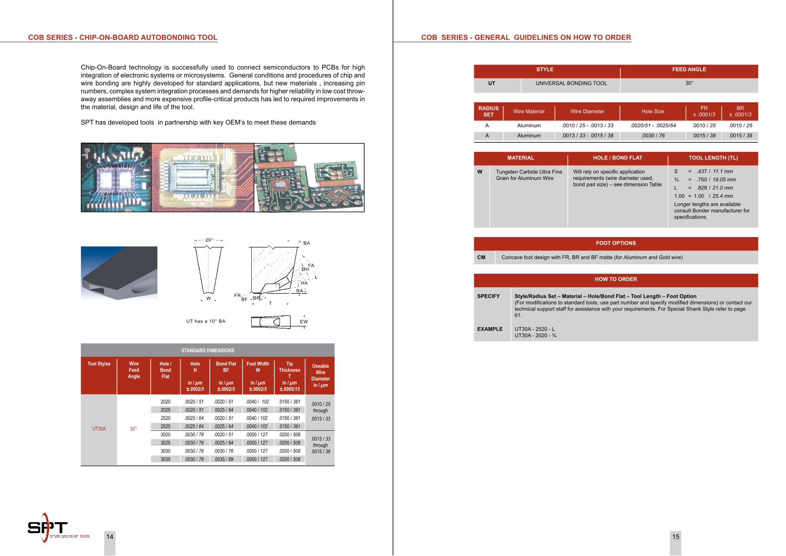
Chip-On-Board technology is successfully used to connect semiconductors to PCBs for high integration of electronic systems or microsystems. General conditions and procedures of chip and wire bonding are highly developed for standard applications, but new materials , increasing pin numbers, complex system integration processes and demands for higher reliability in low cost throw-away assemblies and more expensive profile-critical products has led to required improvements in the material, design and life of the tool.
SPT has developed tools in partnership with key OEM’s to meet these demands
30°
20202025252025253020302530303035
.0020 / 51 .0020 / 51 .0025 / 64 .0025 / 64 .0030 / 76 .0030 / 76 .0030 / 76 .0030 / 76
.0020 / 51 .0025 / 64 .0020 / 51 .0025 / 64 .0020 / 51 .0025 / 64 .0030 / 76 .0035 / 89
.0040 / 102 .0040 / 102 .0040 / 102 .0040 / 102 .0050 / 127 .0050 / 127 .0050 / 127 .0050 / 127
.0150 / 381 .0150 / 381 .0150 / 381 .0150 / 381 .0200 / 508 .0200 / 508 .0200 / 508 .0200 / 508
UT30A
.0010 / 25 through
.0013 / 33
.0013 / 33 through
.0015 / 38
UT has a 10° BA
BA
FA
HA
ØH
RABR
TBF
FRW
20°
EW
16 17
ABT SERiES - GENERAL GUiDELiNES oN hoW To oRDER
STyLE
ABT AUTO BONDING TOOL
FEED ANGLE
38°, 45°, 55°, 60°
C Concave foot design with polished FR and BR with matte finish on BF (matte most commonly used with Aluminum wire) for best results specify when the BF is greater than .0015”/38µm.
CM Concave foot design with FR, BR and BF matte (for Aluminum and Gold wire)
Flat (Optional)
F The FR and BR are polished. A fine matte finish is within the area of the BF.FM The FR, BR and BF are matte.CGM Cross Groove with FR and BR matte (for Gold Wire) with a matte Flat BF. Most commonly used on
manual and semi automatic bonders where pad size restrictions is not an issue. Not recommended for BFsmaller than .0020”/50µm
CCM Cross Groove with FR and BR matte (for Gold Wire) with a Concave used on automatic bonders where wire control is critical and pad size is limited. Not recommended for BFsmaller than .0020”/50µm
FooT oPTioNS
SPECiFy Style – Material – hole/Bond Flat – Tool Length – Foot option (For modifications to standard tools, use part number and specify modified dimensions) or contact our technical support staff for assistance with your requirements. For Special Shank Style refer to page 61.
EXAMPLE 30ABT - W - 2520 - L - CM 180 - DEG - REV (For DIAS Wire Bonder or K&S 8060) 45ABT - TI - 2020 - ¾ - CGM
hoW To oRDER
C Cermet composite for Gold Wire (recommended for Low Temperature bonding)
M Microloy (Osmium-Carbide Alloy) for Gold & Aluminum Wire
Ti Titanium Carbide Composite for Gold Wire
W Tungsten Carbide Ultra Fine Grain for Aluminum Wire
Will rely on specific application requirements (wire diameter used, bond pad size) – see dimension Table* For Oval Hole options please specify HH (Hole Height) & HW (Hole Width)
S = .437 / 11.1 mm¾ = .750 / 19.05 mmL = .828 / 21.0 mm1.00 = 1.00 / 25.4 mmLonger lengths are available consult Bonder manufacturer for specifications.
MATERiAL hoLE / BoND FLAT TooL LENGTh (TL)
.0140 / 356 .0140 / 356 .0140 / 356 .0140 / 356
.0140 / 356 .0140 / 356 .0140 / 356 .0150 / 381 .0150 / 381
.020 / 508 .020 / 508 .020 / 508 .020 / 508 .020 / 508
.0180 / 457 .0180 / 457 .0180 / 457 .0180 / 457 .0180 / 457
.0040 / 102 .0040 / 102 .0040 / 102 .0040 / 102
.0040 / 102 .0040 / 102 .0040 / 102 .0040 / 102 .0040 / 102
.0050 / 127 .0050 / 127 .0050 / 127 .0050 / 127 .0050 / 127
.0050 / 127 .0050 / 127 .0050 / 127 .0050 / 127 .0050 / 127
.0010 / 25 .0010 / 25 .0010 / 25 .0010 / 25
.0010 / 25 .0010 / 25 .0010 / 25 .0010 / 25 .0010 / 25
.0010 / 25 .0010 / 25 .0010 / 25 .0010 / 25 .0010 / 25
.0010 / 25 .0010 / 25 .0010 / 25 .0010 / 25 .0010 / 25
.0010 / 25 .0010 / 25 .0010 / 25 .0010 / 25
.0010 / 25 .0010 / 25 .0010 / 25 .0010 / 25 .0010 / 25
.0010 / 25 .0010 / 25 .0010 / 25 .0010 / 25 .0010 / 25
.0010 / 25 .0010 / 25 .0010 / 25 .0010 / 25 .0010 / 25
.0015 / 38 .0020 / 51 .0025 / 64 .0030 / 76
.0020 / 51 .0025 / 64 .0030 / 76 .0035 / 89 .0040 / 102
.0020 / 51 .0025 / 64 .0030 / 76 .0035 / 89 .0040 / 102
.0020 / 51 .0025 / 64 .0030 / 76 .0035 / 89 .0040 / 102
.0020 / 51 .0020 / 51 .0020 / 51 .0020 / 51
.0025 / 64 .0025 / 64 .0025 / 64 .0025 / 64 .0025 / 64
.0030 / 76 .0030 / 76 .0030 / 76 .0030 / 76 .0030 / 76
.0030 / 76 .0030 / 76 .0030 / 76 .0030 / 76 .0030 / 76
2015202020252030
25202525253025352540
30203025303030353040
30203025303030353040
38°
45°
30ABT
45ABT
.0007 / 18 through
.0013 / 33
.0010 / 25through
.0015 / 38
.0015 / 38through
.0020 / 51
Tip Thickness T
in / µm±.0005/13
Foot Width W
in / µm±.0002/5
Back RadiusBR
in / µm±.0001/3
Front RadiusFR
in / µm±.0001/3
Bond Flat BF
in / µm±.0002/5
UseableWire Diameter
in / µm
HoleH
in / µm±.0002/5
Hole / Bond Flat
Wire Feed Angle
Tool Styles
30ABT
45ABT55ABT60ABT
38°
45°55°60°
ABT SERiES - AUToBoNDiNG TooL
STANDARD DIMENSIONS
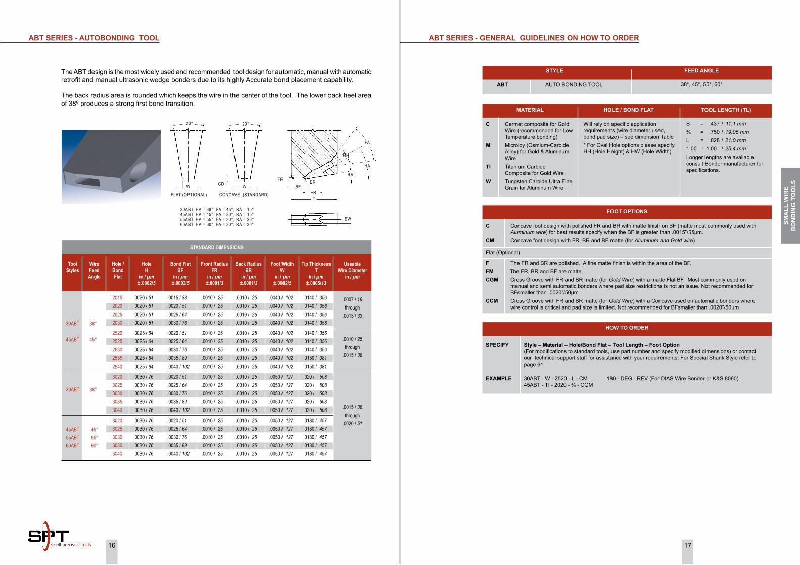
The ABT design is the most widely used and recommended tool design for automatic, manual with automatic retrofit and manual ultrasonic wedge bonders due to its highly Accurate bond placement capability.
The back radius area is rounded which keeps the wire in the center of the tool. The lower back heel area of 38º produces a strong first bond transition.
FLAT (OPTIONAL) CONCAVE (STANDARD)
FA
ØH
HA
RABR
ERT
EW
BFFR
WCD
20°
W
20°
30ABT HA = 38°, FA = 45°, RA = 15°45ABT HA = 45°, FA = 30°, RA = 15°55ABT HA = 55°, FA = 30°, RA = 20°60ABT HA = 60°, FA = 30°, RA = 20° SM
ALL
WiR
E B
oN
DiN
G T
oo
LS

18 19
MiCRoWAVE BoNDiNG TooLS - GENERAL GUiDELiNES oN hoW To oRDER
STyLE
M = MICROWAVE SLIMLINE BACK
FEED ANGLE
30°, 38°, 45°,55°, 60°
FM Flat foot design FR, BR and BF are matte (for Gold Wire)CGM The FR and BR and BF are matte. Not recommended for BFsmaller than .0020”/50µm
FooT oPTioNS
SPECiFy Style – Material – hole/Bond Flat – Tool Length – Foot option (For modifications to standard tools, use part number and specify modified dimensions) or contact our technical support staff for assistance with your requirements. For Special Shank Style refer to page 61.
EXAMPLE M30A –TI –1507 –L - FM M45B –TI –2020 –L - FM M55A –TI –1513 –L – FM
hoW To oRDER
C Cermet composite for Gold Wire (recommended for Low Temperature bonding)
M Microloy (Osmium-Carbide Alloy) for Gold & Aluminum Wire
Ti Titanium Carbide Composite for Gold Wire
W Tungsten Carbide Ultra Fine Grain for Aluminum Wire
Will rely on specific application requirements (wire diameter used, bond pad size) – see dimension Table* For Oval Hole options please specify HH (Hole Height) & HW (Hole Width)
S = .437 / 11.1 mm¾ = .750 / 19.05 mmL = .828 / 21.0 mm1.00 = 1.00 / 25.4 mmLonger lengths are available consult Bonder manufacturer for specifications.
MATERiAL hoLE / BoND FLAT TooL LENGTh (TL)
Tip Thickness T 55°/60°in / µm
±.0005/13
Foot Width
Win / µm
±.0002/5
Back Radius
BRin / µm
±.0001/3
Front Radius
FRin / µm
±.0001/3
Bond Flat BF
in / µm±.0001/3
UseableWire
Diameterin / µm
Hole H
in / µm±.0002/5
Hole / Bond Flat
Tool Styles
Tip Thickness
T 45°in / µm
±.0005/13
Tip Thickness
T 30°in / µm
±.0005/13
.0080 / 203 .0080 / 203 .0080 / 203 .0080 / 203 .0080 / 203 .0080 / 203 .0080 / 203 .0080 / 203 .0080 / 203 .0080 / 203 .0080 / 203 .0080 / 203 .0090 / 229 .0090 / 229 .0090 / 229 .0080 / 203 .0080 / 203 .0080 / 203 .0080 / 203 .0080 / 203 .0080 / 203 .0080 / 203 .0080 / 203 .0080 / 203 .0080 / 203 .0080 / 203 .0080 / 203 .0080 / 203 .0080 / 203 .0080 / 203
.0030 / 76 .0030 / 76 .0030 / 76 .0030 / 76 .0030 / 76 .0030 / 76 .0030 / 76 .0030 / 76 .0030 / 76 .0040 / 102 .0040 / 102 .0040 / 102 .0040 / 102 .0040 / 102 .0040 / 102 .0030 / 76 .0030 / 76 .0030 / 76 .0030 / 76 .0030 / 76 .0030 / 76 .0030 / 76 .0030 / 76 .0030 / 76 .0040 / 102 .0040 / 102 .0040 / 102 .0040 / 102 .0040 / 102 .0040 / 102
.0006 / 15 .0006 / 15 .0006 / 15 .0006 / 15 .0006 / 15 .0006 / 15 .0006 / 15 .0006 / 15 .0006 / 15 .0006 / 15 .0006 / 15 .0006 / 15 .0006 / 15 .0006 / 15 .0006 / 15 .0004 / 10 .0004 / 10 .0004 / 10 .0004 / 10 .0004 / 10 .0004 / 10 .0004 / 10 .0004 / 10 .0004 / 10 .0004 / 10 .0004 / 10 .0004 / 10 .0004 / 10 .0004 / 10 .0004 / 10
.0010 / 25 .0010 / 25 .0010 / 25 .0010 / 25 .0010 / 25 .0010 / 25 .0010 / 25 .0010 / 25 .0010 / 25 .0010 / 25 .0010 / 25 .0010 / 25 .0010 / 25 .0010 / 25 .0010 / 25 .0004 / 10 .0004 / 10 .0004 / 10 .0004 / 10 .0004 / 10 .0004 / 10 .0004 / 10 .0004 / 10 .0004 / 10 .0004 / 10 .0004 / 10 .0004 / 10 .0004 / 10 .0004 / 10 .0004 / 10
.0005 / 13 .0007 / 18 .0010 / 25 .0005 / 13 .0007 / 18 .0010 / 25 .0013 / 33 .0015 / 38 .0020 / 51 .0005 / 13 .0007 / 18 .0010 / 25 .0013 / 33 .0015 / 38 .0020 / 51 .0005 / 13 .0007 / 18 .0010 / 25 .0005 / 13 .0007 / 18 .0010 / 25 .0013 / 33 .0015 / 38 .0020 / 51 .0005 / 13 .0007 / 18 .0010 / 25 .0013 / 33 .0015 / 38 .0020 / 51
.0010 / 25 .0010 / 25 .0010 / 25 .0015 / 38 .0015 / 38 .0015 / 38 .0015 / 38 .0015 / 38 .0015 / 38 .0200 / 51 .0200 / 51 .0200 / 51 .0200 / 51 .0200 / 51 .0200 / 51 .0010 / 25 .0010 / 25 .0010 / 25 .0015 / 38 .0015 / 38 .0015 / 38 .0015 / 38 .0015 / 38 .0015 / 38 .0020 / 51 .0020 / 51 .0020 / 51 .0020 / 51 .0020 / 51 .0020 / 51
100510071010150515071510151315151520200520072010201320152020100510071010150515071510151315151520200520072010201320152020
.0005 / 13through
.0010 / 25
M30A
M38A
M45A
M55A
M60A
M30B
M38B
M45B
M55B
M60B
.0080 / 203 .0080 / 203 .0080 / 203 .0080 / 203 .0080 / 203 .0080 / 203 .0080 / 203 .0080 / 203 .0080 / 203 .0080 / 203 .0080 / 203 .0080 / 203 .0100 / 254 .0100 / 254 .0100 / 254 .0080 / 203 .0080 / 203 .0080 / 203 .0080 / 203 .0080 / 203 .0080 / 203 .0080 / 203 .0080 / 203 .0080 / 203 .0080 / 203 .0080 / 203 .0080 / 203 .0080 / 203 .0080 / 203 .0080 / 203
.0100 / 254 .0100 / 254 .0100 / 254 .0100 / 254 .0100 / 254 .0100 / 254 .0100 / 254 .0100 / 254 .0100 / 254 .0100 / 254 .0100 / 254 .0100 / 254 .0120 / 305 .0120 / 305 .0120 / 305 .0080 / 203 .0080 / 203 .0080 / 203 .0080 / 203 .0080 / 203 .0080 / 203 .0100 / 254 .0100 / 254 .0100 / 254 .0100 / 254 .0100 / 254 .0100 / 254 .0120 / 305 .0120 / 305 .0120 / 305
.0005 / 13through
.0010 / 25
“W dimension .002 to .0025 only for hole size .001 to .0015 ” Refer to page 17 for “How To Order”
STANDARD DIMENSIONS
M SERiES - MiCRoWAVE BoNDiNG TooLS
Microwave devices commonly have bonding pads as small as .001”/ 25µm square. They are typically bonded with .0005”/13µm to .001”/25µm diameter gold wires. Microwave devices have some special requirements that are not seen in monolithic devices special requirements include the variety of chips within the package, step heights within the products that require deep access requirements, as well as critical loop shapes for tuning of the device. We have developed a range of tools to meet the small foot print, and critical loop requirements.
M30 HA = 30°, FA = 45°M38 HA = 38°, FA = 45°M45 HA = 45°, FA = 45°M55 HA = 55°, FA = 30°M60 HA = 60°, FA = 30°
FA
ØH
HA
10°
BR
T
BFFR
W
20°
SMA
LL W
iRE
Bo
ND
iNG
To
oLS

20 21
STANDARD DIMENSIONS
STANDARD NoTCh BoNDiNG TooLS - GENERAL GUiDELiNES oN hoW To oRDER
STyLE
10011002 STANDARD 10° BACK1110
FEED ANGLE
30° 45° 60°
C The FR and BR are polished. A fine matte finish within the area of the BF (Most Commonly Specified)CM The FR,BR and BF are matte.CGM Cross Groove foot design with FR, BR, and BF matte (for Gold Wire). Not recommended for BFsmaller
than .0020”/50µm
Flat (Optional)
F The FR and BR are polished. A fine matte finish within the area of the BF.FM The FR, BR and BF are matte.
Special foot options are available. Consult the factory for recommended dimensions for special foot options.
FooT oPTioNS
Concave (Standard)The Concave Depth (CD) is typically 10 to 15% of the usable wire diameter. There are small side flats on the edges to reduce edge chipping and minimize tool marks on the bond pad if the wire is missing.
SPECiFy Style – Material – hole/Bond Flat – Tool Length – Foot option (For modifications to standard tools, use part number and specify modified dimensions) or contact our technical support staff for assistance with your requirements. For Special Shank Style refer to page 61.
EXAMPLE 1001A-W-2525-L-C 1001B-W-2530-S-C
hoW To oRDER
C Cermet composite for Gold Wire (recommended for Low Temperature bonding)
M Microloy (Osmium-Carbide Alloy) for Gold & Aluminum Wire
Ti Titanium Carbide Composite for Gold Wire
W Tungsten Carbide Ultra Fine Grain for Aluminum Wire
Will rely on specific application requirements (wire diameter used, bond pad size) – see dimension Table* For Oval Hole options please specify HH (Hole Height) & HW (Hole Width)
S = .437 / 11.1 mm¾ = .750 / 19.05 mmL = .828 / 21.0 mm1.00 = 1.00 / 25.4 mmLonger lengths are available consult Bonder manufacturer for specifications.
MATERiAL hoLE / BoND FLAT TooL LENGTh (TL)
STANDARD NoTCh BoNDiNG TooL SERiES
The standard 10º back bonding wedge is designed for use with aluminum wire in all conventional manual bonding machines. The notched tip minimizes wire drag during the looping formation preventing heel cracks and broken wires.
Tip Thickness
T1110
in / µm±.0005/13
Foot Width
W1001, 1002
in / µm±.0002/5
Back Radius
BR
in / µm±.0001/3
Front Radius
FR
in / µm±.0001/3
Bond Flat BF
in / µm±.0002/5
UseableWire
Diameterin / µm
Hole H
in / µm±.0002/5
Hole / Bond Flat
Tool Styles
1001A
1002A
1110A
1001B
1002B
1110B
Foot Width
W1110
in / µm±.0002/5
Tip Thickness
T1002
in / µm±.0005/13
Tip Thickness
T1001
in / µm±.0005/13
.0120 / 305 .0120 / 305 .0140 / 356
.0120 / 305 .0120 / 305 .0120 / 305 .0140 / 356 .0140 / 356 .0140 / 356
.0180 / 457 .0180 / 457 .0180 / 457 .0180 / 457 .0180 / 457
.0120 / 305 .0140 / 356 .0140 / 356
.0120 / 305 .0120 / 305 .0140 / 356 .0140 / 356
.0040 / 102 .0040 / 102 .0040 / 102
.0040 / 102 .0040 / 102 .0040 / 102 .0040 / 102 .0050 / 127 .0050 / 127
.0050 / 127 .0050 / 127 .0050 / 127 .0050 / 127 .0050 / 127
.0040 / 102 .0040 / 102 .0040 / 102
.0040 / 102 .0040 / 102 .0050 / 127 .0050 / 127
.0010 / 25 .0010 / 25 .0010 / 25
.0010 / 25 .0010 / 25 .0010 / 25 .0010 / 25 .0010 / 25 .0010 / 25
.0015 / 38 .0015 / 38 .0015 / 38 .0015 / 38 .0015 / 38
.0010 / 25 .0010 / 25 .0010 / 25
.0010 / 25 .0010 / 25 .0010 / 25 .0010 / 25
.0010 / 25 .0010 / 25 .0010 / 25
.0010 / 25 .0010 / 25 .0010 / 25 .0010 / 25 .0015 / 38 .0015 / 38
.0015 / 38 .0015 / 38 .0015 / 38 .0015 / 38 .0015 / 38
.0015 / 38 .0015 / 38 .0015 / 38
.0015 / 38 .0015 / 38 .0015 / 38 .0015 / 38
.0020 / 51 .0025 / 64 .0030 / 76
.0015 / 38 .0020 / 51 .0025 / 64 .0030 / 76 .0035 / 89 .0040 / 102
.0020 / 51 .0025 / 64 .0030 / 76 .0035 / 89 .0040 / 102
.0020 / 51 .0025 / 64 .0030 / 76
.0015 / 38 .0020 / 51 .0025 / 64 .0030 / 76
.0020 / 51 .0020 / 51 .0020 / 51
.0025 / 64 .0025 / 64 .0025 / 64 .0025 / 64 .0025 / 64 .0025 / 64
.0030 / 76 .0030 / 76 .0030 / 76 .0030 / 76 .0030 / 76
.0020 / 51 .0020 / 51 .0020 / 51
.0025 / 64 .0025 / 64 .0025 / 64 .0025 / 64
202020252030
251525202525253025352540
30203025303030353040
202020252030
2515252025252530
.0007 / 18 through
.0013 / 33
.0010 / 25through
.0015 / 38
.0015 / 38through
.0017 / 40
.0065 / 165 .0065 / 165 .0065 / 165
.0065 / 165 .0065 / 165 .0065 / 165 .0065 / 165 .0065 / 165 .0065 / 165
.0065 / 165 .0065 / 165 .0065 / 165 .0065 / 165 .0065 / 165
.0065 / 165 .0065 / 165 .0065 / 165
.0065 / 165 .0065 / 165 .0065 / 165 .0065 / 165
.0140 / 356 .0140 / 356 .0140 / 356
.0140 / 356 .0140 / 356 .0140 / 356 .0140 / 356 .0150 / 381 .0150 / 381
.0180 / 457 .0180 / 457 .0180 / 457 .0180 / 457 .0180 / 457
.0140 / 356 .0140 / 356 .0140 / 356
.0140 / 356 .0140 / 356 .0140 / 356 .0140 / 356
.0150 / 381 .0150 / 381 .0150 / 381
.0150 / 381 .0150 / 381 .0150 / 381 .0150 / 381 .0180 / 457 .0180 / 457
.0200 / 508 .0200 / 508 .0200 / 508 .0200 / 508 .0200 / 508
.0150 / 381 .0150 / 381 .0150 / 381
.0150 / 381 .0150 / 381 .0150 / 381 .0200 / 508
.0007 / 18 through
.0013 / 33
.0010 / 25through
.0015 / 38
FLAT (OPTIONAL) CONCAVE (STANDARD)
FA
ØH
HARA
BR
TBF
FRWCD
20°
W
20°
1001 HA = 30°, FA = 45°, RA = 15°1002 HA = 45°, FA = 45°, RA = 15°1110 HA = 60°, FA = 30°, RA = 20°
SMA
LL W
iRE
Bo
ND
iNG
To
oLS
22 23
SLiMLiNE NoTCh SERiES - GENERAL GUiDELiNES oN hoW To oRDER
STyLE
1200130014001100
FEED ANGLE
30°45°55°60°
FooT oPTioNS
Concave (Standard)The Concave Depth (CD) is typically 10 to 15% of the usable wire diameter. There are small side flats on the edges to reduce edge chipping and minimize tool marks on the bond pad if the wire is missing.
SPECiFy Style – Material – hole/Bond Flat – Tool Length – Foot option (For modifications to standard tools, use part number and specify modified dimensions) or contact our technical support staff for assistance with your requirements. For Special Shank Style refer to page 61.
EXAMPLE 1200A-W-2525-L-C 1200B-W-2530-S-C 1300A-W-2020-3/4-FM 1110A-W-2025-S-C
hoW To oRDER
SLIMLINE BACK
C The FR and BR are polished. A fine matte finish within the area of the BF (Most Commonly Specified)CM The FR,BR and BF are matte.
F The FR and BR are polished. A fine matte finish within the area of the BF (Most Commonly Specified)FM The FR,BR and BF are matte.
Special foot options are available. Consult the factory for recommended dimensions for special foot options.
Flat (Optional)
CG The FR and BR are polished. A fine matte finish is within the area of the BF. Not recommended for BFsmaller than .0020”/50µm
CGM The FR and BR and BF are matte. Not recommended for BFsmaller than .0020”/50µm
C Cermet composite for Gold Wire (recommended for Low Temperature bonding)
M Microloy (Osmium-Carbide Alloy) for Gold & Aluminum Wire
Ti Titanium Carbide Composite for Gold Wire
W Tungsten Carbide Ultra Fine Grain for Aluminum Wire
Will rely on specific application requirements (wire diameter used, bond pad size) – see dimension Table* For Oval Hole options please specify HH (Hole Height) & HW (Hole Width)
S = .437 / 11.1 mm¾ = .750 / 19.05 mmL = .828 / 21.0 mm1.00 = 1.00 / 25.4 mmLonger lengths are available consult Bonder manufacturer for specifications.
MATERiAL hoLE / BoND FLAT TooL LENGTh (TL)
SLiMLiNE NoTCh SERiES - BoNDiNG TooLS
Hole H
in / µm±.0002/5
Hole / Bond Flat
Tool Styles
Tip Thickness
T1400 / 1100
in / µm±.0005/13
Foot Width
W1200, 1300
in / µm±.0002/5
Back Radius
BR
in / µm±.0001/3
Front Radius
FR
in / µm±.0001/3
Bond Flat BF
in / µm±.0002/5
UseableWire
Diameterin / µm
Foot Width
W1400 / 1100
in / µm±.0002/5
Tip Thickness
T1300
in / µm±.0005/13
Tip Thickness
T1200
in / µm±.0005/13
.0007 / 18 through
.0013 / 33
.0015 / 38through
.0017 / 40
.0017 / 40through
.0022 / 55
1200A
1300A
1400A
1100A
1200B1300B1400B1100B
.0007 / 18 through
.0013 / 33
.0010 / 25through
.0013 / 33
.0120 / 305 .0140 / 356
.0120 / 305 .0120 / 305 .0140 / 356 .0140 / 356 .0140 / 356
.0180 / 457 .0180 / 457 .0180 / 457 .0180 / 457 .0180 / 457
.0210 / 533 .0210 / 533 .0210 / 533 .0210 / 533 .0210 / 533
.0140 / 356 .0140 / 356
.0120 / 305 .0140 / 356 .0140 / 356
.0040 / 102 .0040 / 102
.0040 / 102 .0040 / 102 .0040 / 102 .0050 / 127 .0050 / 127
.0050 / 127 .0050 / 127 .0050 / 127 .0050 / 127 .0050 / 127
.0060 / 152 .0060 / 152 .0060 / 152 .0060 / 152 .0060 / 152
.0040 / 102 .0040 / 102
.0040 / 102 .0050 / 127 .0050 / 127
.0010 / 25 .0010 / 25
.0010 / 25 .0010 / 25 .0010 / 25 .0010 / 25 .0010 / 25
.0015 / 38 .0015 / 38 .0015 / 38 .0015 / 38 .0015 / 38
.0020 / 51 .0020 / 51 .0020 / 51 .0020 / 51 .0020 / 51
.0010 / 25 .0010 / 25
.0010 / 25 .0010 / 25 .0010 / 25
.0010 / 25 .0010 / 25
.0010 / 25 .0010 / 25 .0010 / 25 .0015 / 38 .0015 / 38
.0015 / 38 .0015 / 38 .0015 / 38 .0015 / 38 .0015 / 38
.0020 / 51 .0020 / 51 .0020 / 51 .0020 / 51 .0020 / 51
.0015 / 38 .0015 / 38
.0015 / 38 .0015 / 38 .0015 / 38
.0025 / 64 .0030 / 76
.0020 / 51 .0025 / 64 .0030 / 76 .0035 / 89 .0040 / 102
.0020 / 51 .0025 / 64 .0030 / 76 .0035 / 89 .0040 / 102
.0030 / 76 .0035 / 89 .0040 / 102 .0045 / 114 .0050 / 127
.0025 / 64 .0030 / 76
.0020 / 51 .0025 / 64 .0030 / 76
.0020 / 51 .0020 / 51
.0025 / 64 .0025 / 64 .0025 / 64 .0025 / 64 .0025 / 64
.0030 / 76 .0030 / 76 .0030 / 76 .0030 / 76 .0030 / 76
.0035 / 89 .0035 / 89 .0035 / 89 .0035 / 89 .0035 / 89
.0020 / 51 .0020 / 51
.0025 / 64 .0025 / 64 .0025 / 64
2025 2030
2520 2525 2530 2535 2540
3020 3025 3030 3035 3040
3530 3535 35403545 3550
2025 2030
2520 2525 2530
.0065 / 165 .0065 / 165
.0065 / 165 .0065 / 165 .0065 / 165 .0065 / 165 .0065 / 165
.0065 / 165 .0065 / 165 .0065 / 165 .0065 / 165 .0065 / 165
.0065 / 165 .0065 / 165 .0065 / 165 .0065 / 165 .0065 / 165
.0065 / 165 .0065 / 165
.0065 / 165 .0065 / 165 .0065 / 165
.0140 / 356 .0140 / 356
.0140 / 356 .0140 / 356 .0140 / 356 .0150 / 381 .0150 / 381
.0180 / 457 .0180 / 457 .0180 / 457 .0180 / 457 .0180 / 457
.0220 / 559 .0220 / 559 .0220 / 559 .0220 / 559 .0220 / 559
.0140 / 356 .0140 / 356
.0140 / 356 .0140 / 356 .0140 / 356
.0150 / 381 .0150 / 381
.0150 / 381 .0150 / 381 .0150 / 381 .0180 / 457 .0180 / 457
.0200 / 508 .0200 / 508 .0200 / 508 .0200 / 508 .0200 / 508
.0250 / 635 .0250 / 635 .0250 / 635 .0250 / 635 .0250 / 635
.0150 / 381 .0150 / 381
.0150 / 381 .0150 / 381 .0200 / 508
.0010 / 25through
.0013 / 33
• For wire diameters .0010”/25µm or less consider the Microwave Bonding Tools
• Microwave Style Tool is recommended for Hole = .0020” and BF = 0020” and below.
STANDARD DIMENSIONS
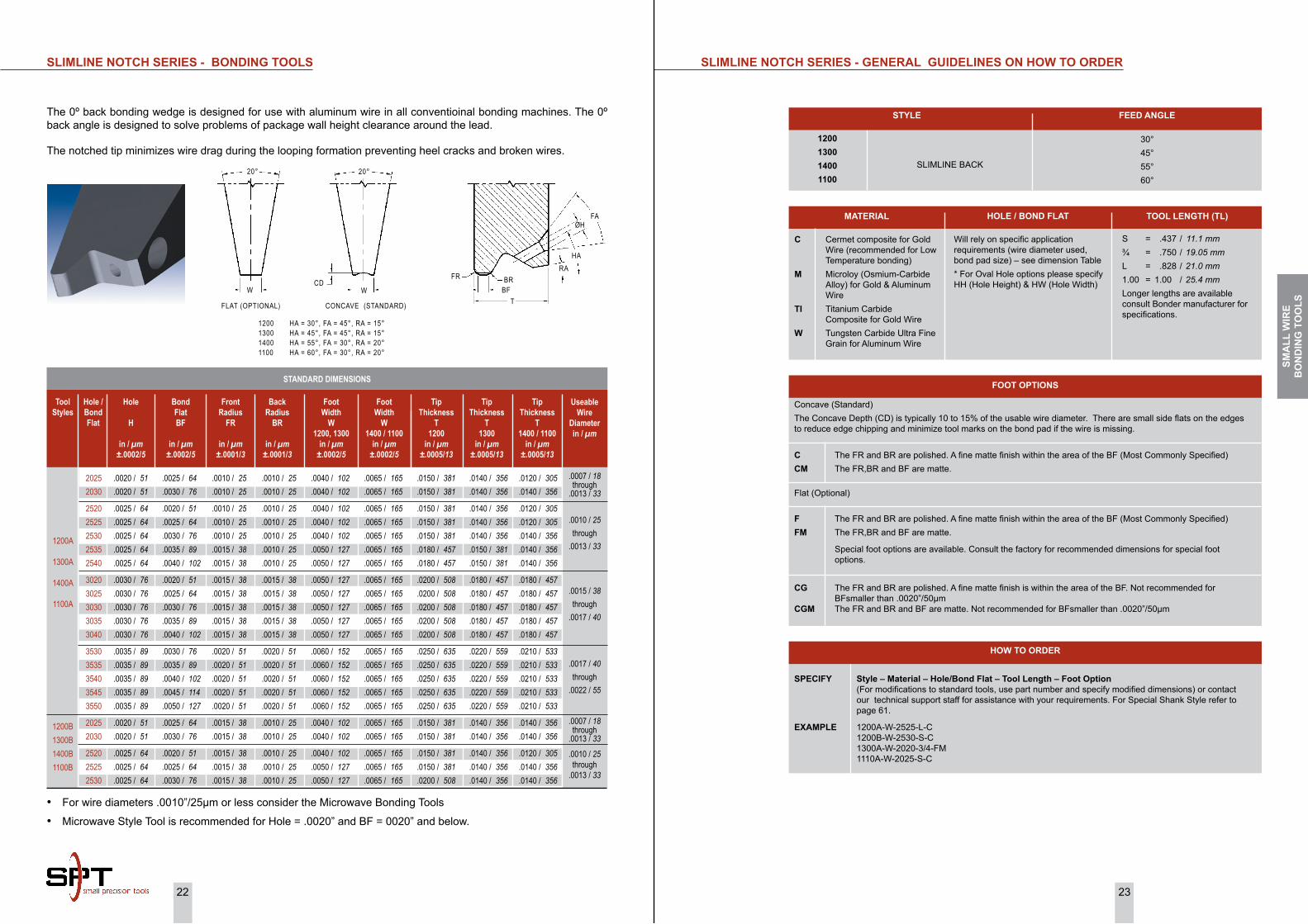
The 0º back bonding wedge is designed for use with aluminum wire in all conventioinal bonding machines. The 0º back angle is designed to solve problems of package wall height clearance around the lead.
The notched tip minimizes wire drag during the looping formation preventing heel cracks and broken wires.
FLAT (OPTIONAL) CONCAVE (STANDARD)
FAØH
HARA
BR
TBF
FR
WCD
20°
W
20°
1200 HA = 30°, FA = 45°, RA = 15°1300 HA = 45°, FA = 45°, RA = 15°1400 HA = 55°, FA = 30°, RA = 20°1100 HA = 60°, FA = 30°, RA = 20°
SMA
LL W
iRE
Bo
ND
iNG
To
oLS

24 25
SPECiAL BoNDiNG TooLS - GENERAL GUiDELiNES oN hoW To oRDER
STyLE
C Cermet composite for Gold Wire (recommended for Low Temperature bonding)
M Microloy (Osmium-Carbide Alloy) for Gold & Aluminum Wire
Ti Titanium Carbide Composite for Gold Wire
W Tungsten Carbide Ultra Fine Grain for Aluminum Wire
Will rely on specific application requirements (wire diameter used, bond pad size) – see dimension Table
S = .437 / 11.1 mm¾ = .750 / 19.05 mmL = .828 / 21.0 mm1.00 = 1.00 / 25.4 mmLonger lengths are available consult Bonder manufacturer for specifications.
MATERiAL FooT LENGTh TooL LENGTh (TL)
SPECiFy Style – Material – Tool Diameter – Tool Length – Foot Design (Specify FL, W, CGD and CGR dimensions). For Special Shank Style refer to page 61.
EXAMPLE 1008A-W-1/16-L-M FL=.003, W = .004, CGD = CGR = .0005
hoW To oRDER
1008A SIDE WIRE BONDING WEDGE STANDARD 10° BACK
M Matte finish on tip
FooT oPTioNSCross Groove Radius
CGRin / µm
±.0001/3
Cross Groove DepthCGD
in / µm±.0001/3
UseableWire Diameter
WDin / µm(Ref)
Foot WidthW
in / µm±.0002/5
Foot LengthFL
in / µm±.0002/5
Tool Styles
.0005 / 13 .0005 / 13 .0005 / 13 .0005 / 13 .0005 / 13 .0005 / 13
.0008 / 19 .0008 / 19 .0008 / 19 .0008 / 19 .0008 / 19
.0010 / 25 .0010 / 25 .0010 / 25 .0010 / 25 .0010 / 25
.0005 / 13 .0005 / 13 .0005 / 13 .0005 / 13 .0005 / 13 .0005 / 13
.0008 / 19 .0008 / 19 .0008 / 19 .0008 / 19 .0008 / 19
.0010 / 25 .0010 / 25 .0010 / 25 .0010 / 25 .0010 / 25
.0020 / 51 to .0040 / 102 .0020 / 51 to .0040 / 102 .0020 / 51 to .0040 / 102
.0020 / 51 to .0040 / 102 .0020 / 51 to .0040 / 102 .0020 / 51 to .0040 / 102
.0030 / 76 to .0050 / 127 .0030 / 76 to .0050 / 127 .0030 / 76 to .0050 / 127 .0030 / 76 to .0050 / 127 .0030 / 76 to .0050 / 127
.0040 / 102 to .0060 / 152 .0040 / 102 to .0060 / 152 .0040 / 102 to .0060 / 152
.0040 / 102 to .0060 / 152 .0040 / 102 to .0060 / 152
1008A 1008A 1008A 1008A 1008A 1008A
1008A 1008A 1008A 1008A 1008A
1008A 1008A 1008A 1008A 1008A
.0030 / 76 .0035 / 89 .0040 / 102 .0045 / 114 .0050 / 127 .0060 / 152
.0045 / 114 .0050 / 127 .0060 / 152 .0070 / 178 .0080 / 203
.0060 / 152 .0070 / 178 .0080 / 203 .0090 / 229 .0100 / 254
.0010 / 25 .0010 / 25 .0010 / 25 .0010 / 25 .0010 / 25 .0010 / 25
.0015 / 38 .0015 / 38 .0015 / 38 .0015 / 38 .0015 / 38
.0020 / 51 .0020 / 51 .0020 / 51 .0020 / 51 .0020 / 51
SPECiAL BoNDiNG TooLS
STANDARD DIMENSIONS
1008A SiDE WiRE BoNDiNG WEDGE
WCGD
CGO
FL
CGR
10°
BA
CK
SMA
LL W
iRE
Bo
ND
iNG
To
oLS

26 27
SPECiAL BoNDiNG TooLS - GENERAL GUiDELiNES oN hoW To oRDER
STyLE
XGR INSULATED WIRE BONDING WEDGE STANDARD 10° BACK
M Matte finish on tip
FooT oPTioNS
SPECiFy Style – Material – Tool Diameter – Tool Length – Foot Design (Specify FL, W, GD, CGD, GR and CGR dimensions) For Special Shank Style refer to page 61.
EXAMPLE XGR – W – 1/16 – L - M FL=.0055, W = .0060, GD = CGD = .0008, GR = CGR = .0010
hoW To oRDER
C Cermet composite for Gold Wire (recommended for Low Temperature bonding)
M Microloy (Osmium-Carbide Alloy) for Gold & Aluminum Wire
Ti Titanium Carbide Composite for Gold Wire
W Tungsten Carbide Ultra Fine Grain for Aluminum Wire
Will rely on specific application requirements (wire diameter used, bond pad size) – see dimension Table
S = .437 / 11.1 mm¾ = .750 / 19.05 mmL = .828 / 21.0 mm1.00 = 1.00 / 25.4 mmLonger lengths are available consult Bonder manufacturer for specifications.
MATERiAL FooT LENGTh TooL LENGTh (TL)
SPECiAL BoNDiNG TooLS
Groove OpeningCross Groove Opening
GO / CGOin / µm
±.0002/5
Groove RadiusCross Groove Radius
GR /CGRin / µm(Ref)
UseableWire Diameter
WDin / µm(Ref)
Groove DepthCross Groove Depth
GD / CGDin / µm
±.0001/3
Foot LengthFL
in / µm±.0002/5
Tool Styles
.0012 / 30 .0012 / 30 .0015 / 38 .0015 / 38 .0020 / 51 .0020 / 51 .0023 / 58 .0023 / 58 .0024 / 61 .0024 / 61 .0028 / 71 .0028 / 71
.0006 / 15 .0006 / 15 .0008 / 20 .0008 / 20 .0010 / 25 .0010 / 25 .0012 / 30 .0012 / 30 .0012 / 30 .0012 / 30 .0015 / 38 .0015 / 38
XGR XGR XGR XGR XGR XGR XGR XGR XGR XGR XGR XGR
.0035 / 89 .0030 / 76 .0035 / 89 .0030 / 76 .0045 / 114 .0055 / 140 .0055 / 140 .0045 / 114 .0060 / 152 .0070 / 178 .0060 / 152 .0070 / 178
.0010 / 25 .0010 / 25 .0010 / 25 .0010 / 25 .0015 / 38 .0015 / 38 .0015 / 38 .0015 / 38 .0020 / 51 .0020 / 51 .0020 / 51 .0020 / 51
Foot WidthW
in / µm±.0002/5
.0040 / 102 .0035 / 89 .0040 / 102 .0035 / 89 .0055 / 140 .0060 / 152 .0060 / 152 .0055 / 140 .0070 / 178 .0080 / 230 .0070 / 178 .0080 / 203
.0005 / 13 .0005 / 13 .0005 / 13 .0005 / 13 .0008 / 20 .0008 / 20 .0008 / 20 .0008 / 20 .0010 / 25 .0010 / 25 .0010 / 25 .0010 / 25
STANDARD DIMENSIONS
XGR iNSULATED WiRE BoNDiNG WEDGE
CGD
CGOGR G
FLGOW
GD
CGR
10°
BACK
SMA
LL W
iRE
Bo
ND
iNG
To
oLS

28 29
GENERAL GUiDELiNES oN hoW To oRDER PF NEEDLES
STyLE
PF20 = PERIPHERAL NEEDLE (.0010”/25µm or less wire diameter)
W Tungsten Carbide Ultra Fine Grain for Aluminum Wire
Will rely on specific application requirements (wire diameter used, bond pad size) – see dimension Table
1” = 1.000” / 25.4 µm½” = .500” / 12.7 µm
MATERiAL BoND FLAT TooL LENGTh (TL)
SPECiFy Style – Length – Tip Diameter (T) – Radius (R) - included Angle (°)
EXAMPLE PF20 - 1” - .0020 - .0003 - 30° PF20 - 1/2” - .0015 - .0002 - 30°
hoW To oRDER
PF NEEDLE
PF20 bonding needles are normally used in Manual Thermocompression Bonders. They are mainly used in microwave applications where the bonding pads are too small to permit normal Ball and Stitch Bonding Techniques. Normally the wire is first positioned over the bonding pad area and then the bonding needle is used to make the bond. Wire diameters of .0010”/25µm or less are normally used in this application.
STANDARD DIMENSIONS
.0010 / 25 .0015 / 38 .0020 / 51
.0002 / 5 .0002 / 5 .0003 / 8
RadiusR
in / µm±.0001/3
Included Angle
30 or 15 30 or 15 30 or 15
Tip DiameterT
in / µm±.0002/5
.0624 ±.0001 in[1.585 ± 0.003 mm]
L - Specify± .015”/0.381mm
See “Tip Details” T R
Tip Details
SMA
LL W
iRE
Bo
ND
iNG
To
oLS

30 31
RiBBoN WiRE TooLS - GENERAL GUiDELiNES oN hoW To oRDER
FM Flat foot design with the FR, BR and BF matte. (Standard)CGM Cross Groove with the FR and BR matte. Not recommended for BFsmaller than .0020”/50µm
FooT oPTioNS
SPECiFy Style – Material – SW/BF – Tool Diameter – Foot option
EXAMPLE RW45 - TI - 1140 - 1/16 - L - CGM RW45 - TI - 0530 - 1/16 - L - FM
hoW To oRDER
STyLE FEED ANGLE
30°, 45°, 55°, 60°RW = RIBBON WIRE SLIMLINE BACK
C Cermet composite for Gold Ribbon Wire (recommended for Low Temperature bonding)
M Microloy (Osmium-Carbide Alloy) for Gold & Aluminum Ribbon Wire
Ti Titanium Carbide Composite for Gold Ribbon Wire
W Tungsten Carbide Ultra Fine Grain for Aluminum Ribbon Wire
Will rely on specific application requirements (wire diameter used, bond pad size) – see dimension Table
S = .437 / 11.1 mm¾ = .750 / 19.05 mmL = .828 / 21.0 mm1.00 = 1.00 / 25.4 mmLonger lengths are available consult Bonder manufacturer for specifications.
MATERiAL hoLE / BoND FLAT TooL LENGTh (TL)
.0140 / 356 .0140 / 356 .0140 / 356
.0140 / 356 .0140 / 356 .0150 / 381 .0150 / 381 .0140 / 356 .0140 / 356 .0150 / 381 .0150 / 381
.0160 / 406 .0160 / 406 .0180 / 457 .0180 / 457 .0180 / 457 .0180 / 457 .0180 / 457
.0055 / 140 .0055 / 140 .0055 / 140
.0065 / 165 .0065 / 165 .0065 / 165 .0065 / 165 .0075 / 191 .0075 / 191 .0075 / 191 .0075 / 191
.0085 / 216 .0085 / 216 .0085 / 216 .0085 / 216 .0125 / 318 .0125 / 318 .0125 / 318
.0020 / 51 .0020 / 51 .0020 / 51
.0025 / 64 .0025 / 64 .0025 / 64 .0025 / 64 .0025 / 64 .0025 / 64 .0025 / 64 .0025 / 64
.0030 / 76 .0030 / 76 .0030 / 76 .0030 / 76 .0030 / 76 .0030 / 76 .0030 / 76
.0040 / 102 .0040 / 102 .0040 / 102
.0050 / 127 .0050 / 127 .0050 / 127 .0050 / 127 .0060 / 152 .0060 / 152 .0060 / 152 .0060 / 152
.0070 / 178 .0070 / 178 .0070 / 178 .0070 / 178 .0110 / 279 .0110 / 279 .0110 / 279
.0005/13to
.0010/25
.0020 / 51 .0020 / 51 .0020 / 51
.0030 / 76 .0030 / 76 .0030 / 76 .0030 / 76 .0040 / 102 .0040 / 102 .0040 / 102 .0040 / 102
.0050 / 127 .0050 / 127 .0050 / 127 .0050 / 127 .0070 / 178 .0070 / 178 .0070 / 178
0420*04250430
05200525*05300540062006250630*0640
0725073007400750112511301140*
RW30RW45RW55RW60
.0020 / 51 .0020 / 51 .0020 / 51
.0020 / 51 .0020 / 51 .0020 / 51 .0020 / 51 .0020 / 51 .0020 / 51 .0020 / 51 .0020 / 51
.0025 / 64 .0025 / 64 .0025 / 64 .0025 / 64 .0025 / 64 .0025 / 64 .0025 / 64
.0160 / 406 .0160 / 406 .0160 / 406
.0160 / 406 .0160 / 406 .0180 / 457 .0180 / 457 .0160 / 406 .0160 / 406 .0180 / 457 .0180 / 457
.0210 / 533 .0210 / 533 .0210 / 533 .0210 / 533 .0210 / 533 .0210 / 533 .0210 / 533
.0030 / 76 .0030 / 76 .0030 / 76
.0030 / 76 .0030 / 76 .0030 / 76 .0030 / 76 .0030 / 76 .0030 / 76 .0030 / 76 .0030 / 76
.0040 / 102 .0040 / 102 .0040 / 102 .0040 / 102 .0040 / 102 .0040 / 102 .0040 / 102
Tip Thickness45° Slots
Tin / µm
±.0005/13
Foot Width
W
in / µm±.0002/5
Slot Thickness
ST
in / µm±.0003/8
Slot Width
SW
in / µm±.0003/8
Ribbon Thickness
RT
in / µmRef
Ribbon Width
RW
in / µmRef
Slot Width/ Bond FlatSW / BF
Tool Styles
Clearance30° & 45°
Slots C
in / µmRef
Tip Thickness
30°/38°Slots T
in / µm±.0005/13
Clearance55° Slots
C
in / µmRef
.0140 / 356 .0120 / 305 .0120 / 305
.0120 / 305 .0120 / 305 .0140 / 356 .0140 / 356 .0120 / 305 .0120 / 305 .0140 / 356 .0140 / 356
.0140 / 356 .0140 / 356 .0160 / 406 .0160 / 406 .0160 / 406 .0160 / 406 .0160 / 406
Tip Thickness
55°/60° Slots T
in / µm±.0005/13
Bond Foot BF
in / µm±.0002/5
.0020 / 51 .0025 / 64 .0030 / 76
.0020 / 51 .0025 / 64 .0030 / 76 .0040 / 102 .0020 / 51 .0025 / 64 .0030 / 76 .0040 / 102
.0025 / 64 .0030 / 76 .0040 / 102 .0050 / 127 .0025 / 64 .0030 / 76 .0040 / 102
.0005/13to
.0010/25
.0005/13to
.0020/51
±.0005/13±.0005/13±.0003/8±.0005/13RefRefSW / BF Ref ±.0005/13Ref ±.0005/13±.0002/5
.0180 / 457 .0180 / 457 .0180 / 457 .0180 / 457 .0180 / 457 .0180 / 457 .0180 / 457 .0180 / 457 .0180 / 457 .0180 / 457 .0180 / 457 .0180 / 457 .0180 / 457 .0180 / 457
.0155 / 394 .0155 / 394 .0155 / 394 .0175 / 445 .0175 / 445 .0175 / 445 .0175 / 445 .0205 / 521 .0205 / 521 .0205 / 521 .0255 / 648 .0255 / 648 .0255 / 648 .0255 / 648
.0030 / 76 .0030 / 76 .0030 / 76 .0030 / 76 .0030 / 76 .0030 / 76 .0030 / 76 .0030 / 76 .0030 / 76 .0030 / 76 .0030 / 76 .0030 / 76 .0030 / 76 .0030 / 76
.0140 / 356 .0140 / 356 .0140 / 356 .0160 / 406 .0160 / 406 .0160 / 406 .0160 / 406 .0190 / 483 .0190 / 483 .0190 / 483 .0240 / 610 .0240 / 610 .0240 / 610 .0240 / 610
.0100 / 254 .0100 / 254 .0100 / 254 .0120 / 305 .0120 / 305 .0120 / 305 .0120 / 305 .0150 / 381 .0150 / 381 .0150 / 381 .0200 / 508 .0200 / 508 .0200 / 508 .0200 / 508
142514301440162516301640*1650192519301940*2425243024402450*
.0025 / 64 .0025 / 64 .0025 / 64 .0025 / 64 .0025 / 64 .0025 / 64 .0025 / 64 .0025 / 64 .0025 / 64 .0025 / 64 .0025 / 64 .0025 / 64 .0025 / 64 .0025 / 64
.0210 / 533 .0210 / 533 .0210 / 533 .0210 / 533 .0210 / 533 .0210 / 533 .0210 / 533 .0210 / 533 .0210 / 533 .0210 / 533 .0210 / 533 .0210 / 533 .0210 / 533 .0210 / 533
.0040 / 102 .0040 / 102 .0040 / 102 .0040 / 102 .0040 / 102 .0040 / 102 .0040 / 102 .0040 / 102 .0040 / 102 .0040 / 102 .0040 / 102 .0040 / 102 .0040 / 102 .0040 / 102
.0140 / 356 .0140 / 356 .0140 / 356 .0140 / 356 .0140 / 356 .0160 / 406 .0160 / 406 .0140 / 356 .0140 / 356 .0160 / 406 .0140 / 356 .0140 / 356 .0160 / 406 .0160 / 406
.0025 / 64 .0030 / 76 .0040 / 102 .0025 / 64 .0030 / 76 .0040 / 102 .0050 / 127 .0025 / 64 .0030 / 76 .0040 / 102 .0025 / 64 .0030 / 76 .0040 / 102 .0050 / 127
.0005/13to
.0020/51
RiBBoN WiRE BoNDiNG TooLS
• * Most commonly specified• Standard FR and BR : FR = .0010” / 25µm and BR = .0003” / 8µm is standard.• Max Ribbon size for a vertical shank (1/16) is .012” / 305µm ribbon.
STANDARD DIMENSIONS
FAST
HARA
T
SW
BFW
20°
RW30 HA = 30°, FA = 45°, RA = 10°RW45 HA = 45°, FA = 45°, RA = 20°RW55 HA = 55°, FA = 30°, RA = 20°RW60 HA = 60°, FA = 30°, RA = 20°
ST
FR BR
SMA
LL W
iRE
Bo
ND
iNG
To
oLS

32 33
The evolution of the groove designs have evolved by necessity due to the progress made in the development of better materials for bonding, Mold compounds, improved lead frame designs to minimize package delamination, faster bonders and the shrinkage of real-estate to bond to has pushed the tool design to more of a “V” groove type tool with no-hole allowing for bonding in tight conditions where other tools designs are becoming obsolete. Initially bigger bonds were considered to be more reliable but basically were used as a band-aid to compensate for the inequities of the materials.
The integration of power and logic (SmartMos®) has set new standards for bonding large wire. The package, silicon, and pad size has shrunk by 25 to 30% in some cases pushing the design rules to its limit.
For special bonding requirements contact the factory for designs and availability.
GRooVE DESiGNS
There are 5 different styles of groove designs. They include Concave, Inline groove, “V” groove, Deep “V” groove and “U” groove designs
1009A CoNCAVE FooT STyLE 1016A iNLiNE GRooVE STyLE
AB16 V GRooVE STyLE oSG7 DEEP V GRooVE STyLE
1015A U GRooVE STyLE
LARGE WiRE BoNDiNG TooLS
Large Wire Bonding is defined as wire diameters in the range of .003”/75µm to .020”/500µm. Tools designed to bond .003” wire diameter will bond 75µm wire diameters equally well.
Wire material most commonly used is 99.99% aluminum however, aluminum-magnesium (AlMg) is also used. The choice of aluminum wire used depends largely on the material being bonded to (die pad metallization). The AlMg wire material is much harder than pure aluminum. Materials of approximately the same hardness bond together best. That is, if the die metallization is soft, then the softer pure aluminum wire will form a weldment easier than the harder AlMg. If the metallization is harder then the AlMg wire material will work best. Many times the metallization of the die is soft and the metallization of the lead is hard…making the wire material optimum for one area and opposite for the other bonding target. If one is having a weldment problem with one particular metallization (die / lead) it is good to keep in mind the hardness differences between the two targets can help you to pin point the cause of the bonding issues. In most cases, however, the wire composition is specified for the product and the bond engineer has no choice as to whether 99.9% Al or AlMg can be used.
There are four basic types of large wire tools geometry, and Groove designs most commonly used for wire bonding. These designs overtime have been driven through the collaboration between the OEM and customer. The designs overtime have been the standards for the industry. The tool geometry are dedicated to a particular wirebonder. Groove designs, bond lengths are commonly driven by the customer requirements.
TooL GEoMETRy
There are 4 basic types of large wire tool geometry. They include notch tools, L-notch tools, AutoBonding tools®, and No-hole tools.
The No-hole style tools require a separate wire feed guide which guides the wire just behind the tool, and travels in unison with the tools movement. All other types of tools have an integrated wire feed hole at various angles to the bond plane. The bonding machine being used determines the tool design that is chosen. AutoBonding Tools® help guide the wire directly under the foot this design is commonly used where L-notch tools experience wire control problems where different bonding heights and extreme long wires are bonded.
30D6 STyLE 4516 STyLE
oSG7 STyLE AB16 STyLE
LAR
GE
WiR
E B
oN
DiN
G T
oo
LS

34 35
(Ref)(Ref)±.0010/25 ±.0010/25 ±.0005/13Min (75%)
iNLiNE GRooVE No-hoLE TooLS
STANDARD DIMENSIONS
iNLiNE GRooVE No-hoLE TooLS - GENERAL GUiDELiNES oN hoW To oRDER
1/8 .1249 / 3.172 .110 / 2.794
Tool Dia
TD in / mm
±.0001”/3µmSpecified
Length
TDFin / mm
±.0005”/13µm
TLin / mm
±.005”/130µm
2.50 2.500 / 63.50
STyLE MATERiAL
W : Tungsten Carbide Ultra Fine Grain for Aluminum Wire
oSG7 : 70° Deep “V” Groove Specify Wire Size
WiRE SizE
G The FR and BR are polished and a fine matte finish is within the area of the groove. (Standard)GM The FR, BR and groove have a matte finish
FooT oPTioNS
SPECiFy Style - Wire - Material - Tool Diameter - Tool Length - Foot option (For modifications to standard tools, use part number and specify modified dimensions or contact our technical support staff for assistance with your requirements). For Shank Style refer to page 62.
EXAMPLE OSG7 - 10 - W - 1/8 - 2.50 - G
hoW To oRDER
oSG7 STyLE
Tool Styles - Wire Size
Back Radius
BRin / µm(Ref)
Front Radius
FRin / µm(Ref)
Foot Length
FLin / µm
±.0005/13
Useable Wire Diameter
WDin / µm
Foot Width
Win / µm
±.0005/13
Groove Opening
Bin / µm
±.0003/8
Groove Depth
GDin / µm
Min
OSG7- 4OSG7- 5OSG7- 6OSG7- 7OSG7- 8
.0040 / 100 .0050 / 125 .0060 / 150 .0070 / 175 .0080 / 200
.0054 / 137 .0068 / 173 .0082 / 208 .0096 / 244 .0109 / 277
.0027 / 69 .0034 / 86 .0041 / 104 .0048 / 122 .0054 / 137
.0114 / 290 .0142 / 361 .0170 / 432 .0199 / 505 .0226 / 574
.0080 / 200 .0100 / 254 .0120 / 305 .0140 / 356 .0160 / 406
.0046 / 117 .0057 / 145 .0068 / 173 .0080 / 203 .0091 / 231
.0027 / 69 .0034 / 86 .0040 / 102 .0048 / 122 .0055 / 140
OSG7- 10OSG7- 12OSG7- 14OSG7- 15OSG7- 16OSG7- 18OSG7- 20
.0100 / 250 .0120 / 300 .0140 / 356 .0150 / 381 .0160 / 400 .0180 / 450 .0200 / 500
.0136 / 345 .0163 / 414 .0190 / 483 .0204 / 518 .0211 / 536 .0245 / 622 .0272 / 691
.0068 / 173 .0082 / 208 .0095 / 241 .0102 / 259 .0106 / 269 .0122 / 310 .0136 / 345
.0283 / 719 .0340 / 864 .0396 / 1006 .0425 / 1080 .0440 / 1118 .0510 / 1295 .0566 / 1438
.0200 / 508 .0240 / 610 .0280 / 711 .0300 / 762 .0320 / 813 .0363 / 922 .0400 / 1016
.0122 / 310 .0146 / 371 .0171 / 434 .0183 / 465 .0195 / 495 .0220 / 559 .0244 / 620
.0075 / 191 .0090 / 229 .0105 / 267 .0113 / 287 .0118 / 300 .0140 / 356 .0150 / 381
10°
BR
FLFRB
GD
70°
W
30° (Typ)
LAR
GE
WiR
E B
oN
DiN
G T
oo
LS

36 37
±.0005/13(Ref)±.0005/13 Min ±.0039/100±.0005/13
STANDARD DIMENSIONS
iNLiNE GRooVE No-hoLE TooLS - GENERAL GUiDELiNES oN hoW To oRDER
1/161/8
2mm3mm
.0624 / 1.585 .1249 / 3.172 .0785 / 1.995 @ .1180 / 2.997
.0570 / 1.448 * .0937 / 2.378 *** .0630 / 1.600 * .0985 / 2.502 **
Tool Dia
TD in / mm
±.0001”/3µmSpecified
Length
TDFin / mm
±.0005”/13µm
TLin / mm
±.005”/130µm
L1.00
20mm29mm
.828 / 21.0 1.000 / 25.4
.787 / 20.0 1.142 / 29.0
STyLE MATERiAL
W : Tungsten Carbide Ultra Fine Grain for Aluminum Wire
CKVD : 70° Deep “V” Groove Specify Wire Size
WiRE SizE
G The FR and BR are polished and a fine matte finish is within the area of the groove. (Standard)GM The FR, BR and groove have a matte finish
FooT oPTioNS
SPECiFy Style - Wire - Material - Tool Diameter - Tool Length - Foot option (For modifications to standard tools, use part number and specify modified dimensions or contact our technical support staff for assistance with your requirements). For Shank Style refer to page 62.
EXAMPLE CKVD - 250 - W - 2mm - 29mm - G
hoW To oRDER
Length 29mm for Deep Access* limited size availability.** .110” / 2.79mm TDF supplied if required by foot geometry.*** .1180” / 3.00mm TDF supplied if required by foot geometry.@ Tolerance +0 / - .0002” / 5µm
NoTE
CKVD STyLE
iNLiNE GRooVE No-hoLE TooLS
Tool Styles - Wire Size
Foot Width
Win / µm
±.0003/8
Front/Back Radius
FR = BRin / µm(Ref)
Foot Length
FLin / µm
±.0003/8
Useable Wire Diameter
WDin / µm
Groove Depth
GDin / µm
Min
Relief E
in / µm±.0039/100
Groove Opening
Bin / µm
±.0003/8
CKVD-100CKVD-125CKVD-150CKVD-175CKVD-200
.0040 / 100 .0050 / 125 .0060 / 150 .0070 / 175 .0080 / 200
.0079 / 200 .0098 / 250 .0118 / 300 .0138 / 350 .0157 / 400
.0012 / 30 .0015 / 38 .0018 / 45 .0021 / 53 .0024 / 61
.0098 / 250 .0118 / 300 .0138 / 350 .0157 / 400 .0177 / 450
.0028 / 71 .0035 / 89 .0042 / 107 .0049 / 124 .0056 / 142
.0390 / 1000 .0390 / 1000 .0390 / 1000 .0390 / 1000 .0390 / 1000
.0043 / 109 .0054 / 137 .0065 / 165 .0076 / 193 .0087 / 221
CKVD-250CKVD-300CKVD-350CKVD-380CKVD-400CKVD-500
.0100 / 250 .0120 / 300 .0140 / 350 .0150 / 380 .0160 / 400 .0200 / 500
.0197 / 500 .0236 / 600 .0276 / 700 .0299 / 760 .0315 / 800 .0394 / 1000
.0030 / 76 .0035 / 89 .0041 / 104 .0045 / 114 .0047 / 119 .0059 / 150
.0217 / 551 .0256 / 650 .0299 / 760 .0323 / 820 .0343 / 871 .0433 / 110
.0070 / 178 .0084 / 213 .0098 / 249 .0106 / 269 .0112 / 284 .0140 / 356
.0590 / 1500 .0590 / 1500 .0590 / 1500 .0590 / 1500 .0590 / 1500 .0590 / 1500
.0108 / 274 .0130 / 330 .0152 / 386 .0165 / 419 .0173 / 439 .0217 / 551
BRFLFR
GD
B
20°
W
70°
LAR
GE
WiR
E B
oN
DiN
G T
oo
LS

38 39
STANDARD DIMENSIONS
iNLiNE GRooVE No-hoLE TooLS - GENERAL GUiDELiNES oN hoW To oRDER
STyLE MATERiAL
W : Tungsten Carbide Ultra Fine Grain for Aluminum Wire
CK : Inline Groove Specify Wire Size
WiRE SizE
G The FR and BR are polished and a fine matte finish is within the area of the groove. (Standard)GM The FR, BR and groove have a matte finish
FooT oPTioNS
SPECiFy Style - Wire - Material - Tool Diameter - Tool Length - Foot option (For modifications to standard tools, use part number and specify modified dimensions or contact our technical support staff for assistance with your requirements). For Shank Style refer to page 62.
EXAMPLE CK - 200 - W - 2mm - 29mm - G CK - 150 - W - 2mm - 29mm - GM CK - 200 - W - 3mm - 20mm - G
hoW To oRDER
* limited size availability.** .110” / 2.79mm TDF supplied if required by foot geometry.*** .1180” / 3.00mm TDF supplied if required by foot geometry.@ Tolerance +0 / - .0002” / 5µm
NoTE
1/161/8
2mm3mm
.0624 / 1.585 .1249 / 3.172 .0785 / 1.995 @ .1180 / 2.997
.0570 / 1.448 * .0937 / 2.378 *** .0630 / 1.600 * .0985 / 2.502 **
L1.00
20mm29mm
.828 / 21.0 1.000 / 25.4
.787 / 20.0 1.142 / 29.0
Tool Dia
TD in / mm
±.0001”/3µmSpecified
Length
TDFin / mm
±.0005”/13µm
TLin / mm
±.005”/130µm
CK STyLE
iNLiNE GRooVE No-hoLE TooLS
Tool Styles - Wire Size
Flat
Fin / µm(Ref)
Front/Back Radius
FR = BRin / µm
±.0005/13
Foot Length
FLin / µm
±.0005/13
Useable Wire Diameter
WDin / µm
Foot Width
Win / µm
±.0005/13
Groove Radius
GRin / µm
±.0002/5
Groove Depth
GDin / µm
±.0002/5
.0018 / 46 .0024 / 61 .0030 / 76 .0035 / 89 .0041 / 104 .0047 / 119
CK-75CK-100CK-125CK-150CK-175CK-200
.0030 / 75 .0040 / 100 .0050 / 125 .0060 / 150 .0070 / 175 .0080 / 200
.0030 / 76 .0039 / 99 .0049 / 124 .0059 / 150 .0069 / 175 .0079 / 201
.0018 / 46 .0024 / 61 .0030 / 76 .0035 / 89 .0041 / 104 .0047 / 119
.0065 / 165 .0090 / 229 .0110 / 279 .0130 / 330 .0150 / 381 .0170 / 432
.0075 / 191 .0100 / 254 .0120 / 305 .0150 / 381 .0170 / 432 .0200 / 508
.0010 / 25 .0014 / 36 .0017 / 43 .0021 / 53 .0024 / 61 .0028 / 71
BRFGR
FL
FR
GD
W
20°
LAR
GE
WiR
E B
oN
DiN
G T
oo
LS

40 41
STANDARD DIMENSIONS
iNLiNE GRooVE AUToBoNDiNG TooLS - GENERAL GUiDELiNES oN hoW To oRDER
STyLE FEED ANGLE
45°60° wire feed available with slimline45CK : Inline and 70° “V” Groove
G The FR and BR are polished and a fine matte finish is within the area of the groove. (Standard)GM The FR, BR and groove have a matte finish
FooT oPTioNS
SPECiFy Style - Wire - Material - Tool Diameter - Tool Length - Foot option (For modifications to standard tools, use part number and specify modified dimensions or contact our technical support staff for assistance with your requirements). For Shank Style refer to page 62.
EXAMPLE 45CK - 200 - W - 2mm - 29mm - G
hoW To oRDER
MATERiAL
W : Tungsten Carbide Ultra Fine Grain for Aluminum Wire
Specify Wire Size
WiRE SizE
1/161/8
2mm3mm
.0624 / 1.585 .1249 / 3.172 .0785 / 1.995 @ .1180 / 2.997
.0570 / 1.448 * .0937 / 2.378 *** .0630 / 1.600 * .0985 / 2.502 **
Tool Dia
TD in / mm
±.0001”/3µmSpecified
Length
TDFin / mm
±.0005”/13µm
TLin / mm
±.005”/130µm
L1.00
20mm29mm
.828 / 21.0 1.000 / 25.4
.787 / 20.0 1.142 / 29.0
* limited size availability.** .110” / 2.79mm TDF supplied if required by foot geometry.*** .1180” / 3.00mm TDF supplied if required by foot geometry.@ Tolerance +0 / - .0002” / 5µm
NoTE
iNLiNE GRooVE AUToBoNDiNG TooLS
45CK-7545CK-10045CK-12545CK-15045CK-17545CK-200
.0030 / 75 .0040 / 100 .0050 / 125 .0060 / 150 .0070 / 175 .0080 / 200
.0015 / 38 .0020 / 51 .0025 / 64 .0030 / 76 .0035 / 89 .0039 / 100
.0070 / 178 .0073 / 185 .0086 / 219 .0100 / 254 .0105 / 267 .0106 / 270
.0055 / 140 .0059 / 150 .0074 / 188 .0089 / 226 .0103 / 262 .0118 / 300
.0070 / 178 .0079 / 200 .0098 / 250 .0118 / 300 .0138 / 350 .0157 / 400
.0018 / 46 .0026 / 65 .0032 / 81 .0038 / 97 .0045 / 114 .0051 / 130
.0270 / 686 .0290 / 737 .0340 / 864 .0400 / 1016 .0470 / 1194 .0540 / 1372
Tool Styles - Wire Size
Groove Opening
Bin / µm
±.0003/18
Front/Back Radius
FR = BRin / µm(Ref)
Foot Length
FLin / µm
±.0005/13
Hole Diameter
in / µm±.0005/13
Useable Wire Diameter
WDin / µm
Foot Width
Win / µm
±.0005/13
Groove Depth
GDin / µm
Min
Tip Length T
in / µm±.0010/25
.0032 / 81 .0043 / 110 .0054 / 137 .0065 / 165 .0076 / 193 .0087 / 221
.0100 / 250 .0046 / 125 .0133 / 338 .0148 / 376 .0197 / 500 .0064 / 163 .0063 / 1600 .0108 / 27445CK-250
±.0005/13(Ref)±.0005/13±.0005/13 ±.0005/13 Min±.0010/25
45CK STyLE
ØH
45°
BR
T
GD
FLFR
W
B
20°
70°
45°
LAR
GE
WiR
E B
oN
DiN
G T
oo
LS

42 43
STANDARD DIMENSIONS
iNLiNE GRooVE No-hoLE TooLS - GENERAL GUiDELiNES oN hoW To oRDER
G The FR and BR are polished and a fine matte finish is within the area of the groove. (Standard)GM The FR, BR and groove have a matte finish
FooT oPTioNS
SPECiFy Style - Wire - Material - Tool Diameter - Tool Length - Foot option (For modifications to standard tools, use part number and specify modified dimensions or contact our technical support staff for assistance with your requirements). For Shank Style refer to page 62.
EXAMPLE LWD6 - 250 - W - 1/8 - 1.00 - G LWD6 - 350 - W - 1/8 - 1.00 - G
hoW To oRDER
STyLE MATERiAL
W : Tungsten Carbide Ultra Fine Grain for Aluminum Wire
LWD6 : 60° Deep “V” Groove Specify Wire Size
WiRE SizE
* limited size availability.** .110” / 2.79mm TDF supplied if required by foot geometry.*** .1180” / 3.00mm TDF supplied if required by foot geometry.@ Tolerance +0 / - .0002” / 5µm
NoTE
1/161/8
2mm3mm
.0624 / 1.585 .1249 / 3.172 .0785 / 1.995 @ .1180 / 2.997
.0570 / 1.448 * .0937 / 2.378 *** .0630 / 1.600 * .0985 / 2.502 **
L1.00
20mm30mm
.828 / 21.0 1.000 / 25.4
.787 / 20.0 1.181 / 30.0
Tool Dia
TD in / mm
±.0001”/3µmSpecified
Length
TDFin / mm
±.0005”/13µm
TLin / mm
±.005”/130µm
iNLiNE GRooVE No-hoLE TooLS
Tool Styles - Wire Size
Foot Width
Win / µm
±.0003/8
Front/Back Radius
FR = BRin / µm(Ref)
Foot Length
FLin / µm
±.0003/8
Useable Wire Diameter
WDin / µm
Groove Depth
GDin / µm
Min
Relief E
in / µm ±.010/254 -0
Groove Opening
Bin / µm
±.0003/8
LWD6-75LWD6-100LWD6-125LWD6-150LWD6-175LWD6-200
.0030 / 75 .0040 / 100 .0050 / 125 .0060 / 150 .0070 / 175 .0080 / 200
.0075 / 191 .0100 / 254 .0120 / 305 .0140 / 356 .0155 / 394 .0175 / 445
.0015 / 38 .0020 / 51 .0025 / 64 .0030 / 76 .0035 / 89 .0040 / 102
.0080 / 203 .0105 / 267 .0130 / 330 .0155 / 394 .0180 / 457 .0205 / 521
.0021 / 53 .0028 / 71 .0035 / 89 .0042 / 107 .0049 / 124 .0056 / 142
.0200 / 508 .0200 / 508 .0200 / 508 .0200 / 508 .0200 / 508 .0200 / 508
.0033 / 84 .0044 / 112 .0055 / 140 .0066 / 168 .0077 / 196 .0088 / 224
±.0005/13(Ref)±.0005/13 Min ±.010/254 -0
±.0005/13
LWD6-250LWD6-300LWD6-350LWD6-380LWD6-400LWD6-500
.0100 / 250 .0120 / 300 .0140 / 350 .0150 / 380 .0160 / 400 .0200 / 500
.0215 / 546 .0255 / 648 .0295 / 749 .0315 / 800 .0335 / 851 .0415 / 1054
.0050 / 127 .0060 / 152 .0070 / 178 .0075 / 191 .0080 / 203 .0100 / 254
.0270 / 686 .0305 / 775 .0330 / 838 .0345 / 876 .0355 / 902 .0445 / 1130
.0070 / 178 .0084 / 213 .0098 / 249 .0105 / 267 .0112 / 284 .0140 / 356
.0400 / 1016 .0400 / 1016 .0400 / 1016 .0600 / 1524 .0600 / 1524 .0600 / 1524
.0110 / 279 .0132 / 335 .0154 / 391 .0165 / 419 .0176 / 447 .0220 / 559
LWD6 STyLE
BR
FL
GD
FR
B
20°
W
60°
LAR
GE
WiR
E B
oN
DiN
G T
oo
LS

44 45
STANDARD DIMENSIONS
CoNCAVE No hoLE TooLS - GENERAL GUiDELiNES oN hoW To oRDER
C The FR and BR are polished and a fine matte finish is within the area of the groove. (Standard)CM The FR, BR and groove have a matte finish
FooT oPTioNS
SPECiFy Style - Wire - Material - Tool Diameter - Tool Length - Foot option (For modifications to standard tools, use part number and specify modified dimensions or contact our technical support staff for assistance with your requirements). For Shank Style refer to page 62.
EXAMPLE 1009A - 5 - W - 3mm - L - CM 1009A - 8 - W - 1/8 - L - C
hoW To oRDER
STyLE MATERiAL
W : Tungsten Carbide Ultra Fine Grain for Aluminum Wire
1009A : Concave No-Hole Specify Wire Size
WiRE SizE
Tool Dia
TD in / mm
±.0001”/3µmSpecified
Length
TDFin / mm
±.0005”/13µm
TLin / mm
±.005”/130µm
1/161/8
2mm3mm
.0624 / 1.585 .1249 / 3.172 .0785 / 1.995 @ .1180 / 2.997
.0570 / 1.448 * .0937 / 2.378 *** .0630 / 1.600 * .0985 / 2.502 **
L1.00
20mm29mm
.828 / 21.0 1.000 / 25.4
.787 / 20.0 1.142 / 29.0
* limited size availability.** .110” / 2.79mm TDF supplied if required by foot geometry.*** .1180” / 3.00mm TDF supplied if required by foot geometry.@ Tolerance +0 / - .0002” / 5µm
NoTE
CoNCAVE No-hoLE BoNDiNG TooLS
1009A STyLE
.0010 / 25 .0013 / 33 .0016 / 41 .0018 / 46 .0020 / 51
Tool Styles - Wire Size
Back Radius
BRin / µm
±.0003/8
Front Radius
FRin / µm
±.0005/13
Foot Length
FLin / µm
±.0005/13
Useable Wire Diameter
WDin / µm
Flat
Fin / µm(Ref)
Concave Depth
CDin / µm
±.0002/5
Foot Width
Win / µm
±.0005/13
1009A-41009A-51009A-61009A-71009A-8
.0040 / 100 .0050 / 125 .0060 / 150 .0070 / 175 .0080 / 200
.0050 / 127 .0050 / 127 .0060 / 152 .0060 / 152 .0060 / 152
.0080 / 203 .0090 / 229 .0090 / 229 .0090 / 229 .0090 / 229
.0160 / 406 .0180 / 457 .0180 / 457 .0180 / 457 .0180 / 457
.0055 / 140 .0070 / 178 .0065 / 165 .0065 / 165 .0065 / 165
.0120 / 305 .0150 / 381 .0180 / 457 .0210 / 533 .0240 / 610
10°
20°
F
FLW
CD
LAR
GE
WiR
E B
oN
DiN
G T
oo
LS
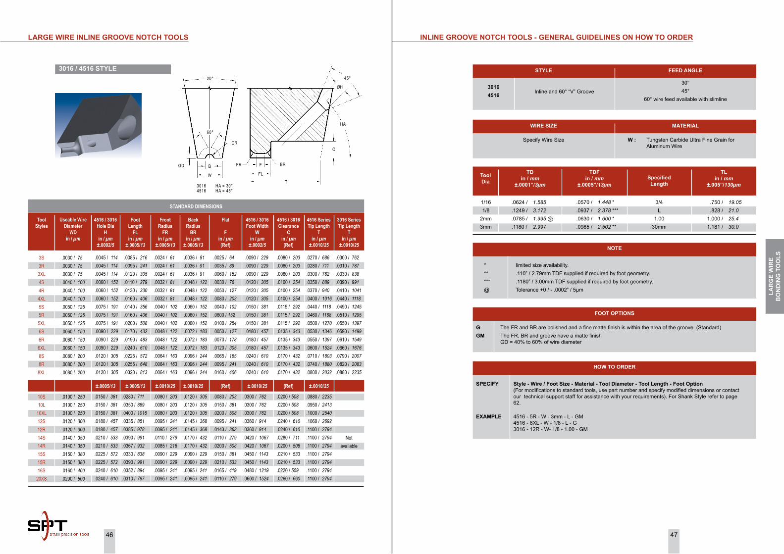
46 47
* limited size availability.** .110” / 2.79mm TDF supplied if required by foot geometry.*** .1180” / 3.00mm TDF supplied if required by foot geometry.@ Tolerance +0 / - .0002” / 5µm
NoTE
1/161/8
2mm3mm
.0624 / 1.585 .1249 / 3.172 .0785 / 1.995 @ .1180 / 2.997
.0570 / 1.448 * .0937 / 2.378 *** .0630 / 1.600 * .0985 / 2.502 **
3/4L
1.0030mm
.750 / 19.05 .828 / 21.0 1.000 / 25.4 1.181 / 30.0
Tool Dia
TD in / mm
±.0001”/3µmSpecified
Length
TDFin / mm
±.0005”/13µm
TLin / mm
±.005”/130µm
±.0005/13 (Ref)±.0010/25±.0010/25±.0005/13 ±.0010/25 ±.0010/25(Ref)
iNLiNE GRooVE NoTCh TooLS - GENERAL GUiDELiNES oN hoW To oRDER
STyLE FEED ANGLE
30°45°
60° wire feed available with slimline
30164516
G The FR and BR are polished and a fine matte finish is within the area of the groove. (Standard)GM The FR, BR and groove have a matte finish
GD = 40% to 60% of wire diameter
FooT oPTioNS
SPECiFy Style - Wire / Foot Size - Material - Tool Diameter - Tool Length - Foot option (For modifications to standard tools, use part number and specify modified dimensions or contact our technical support staff for assistance with your requirements). For Shank Style refer to page 62.
EXAMPLE 4516 - 5R - W - 3mm - L - GM 4516 - 8XL - W - 1/8 - L - G 3016 - 12R - W- 1/8 - 1.00 - GM
hoW To oRDER
MATERiAL
W : Tungsten Carbide Ultra Fine Grain for Aluminum Wire
Specify Wire Size
WiRE SizE
Inline and 60° “V” Groove
3S3R3XL4S4R4XL5S5R5XL6S6R6XL8S8R8XL
.0030 / 75 .0030 / 75 .0030 / 75 .0040 / 100 .0040 / 100 .0040 / 100 .0050 / 125 .0050 / 125 .0050 / 125 .0060 / 150 .0060 / 150 .0060 / 150 .0080 / 200 .0080 / 200 .0080 / 200
.0300 / 762 .0310 / 787 .0330 / 838 .0390 / 991 .0410 / 1041 .0440 / 1118 .0490 / 1245 .0510 / 1295 .0550 / 1397 .0590 / 1499 .0610 / 1549 .0660 / 1676 .0790 / 2007 .0820 / 2083 .0880 / 2235
.0025 / 64 .0035 / 89 .0060 / 152 .0030 / 76 .0050 / 127 .0080 / 203 .0040 / 102 .0600 / 152 .0100 / 254 .0050 / 127 .0070 / 178 .0120 / 305 .0065 / 165 .0095 / 241 .0160 / 406
.0036 / 91 .0036 / 91 .0036 / 91 .0048 / 122 .0048 / 122 .0048 / 122 .0060 / 152 .0060 / 152 .0060 / 152 .0072 / 183 .0072 / 183 .0072 / 183 .0096 / 244 .0096 / 244 .0096 / 244
.0024 / 61 .0024 / 61 .0024 / 61 .0032 / 81 .0032 / 81 .0032 / 81 .0040 / 102 .0040 / 102 .0040 / 102 .0048 / 122 .0048 / 122 .0048 / 122 .0064 / 163 .0064 / 163 .0064 / 163
.0085 / 216 .0095 / 241 .0120 / 305 .0110 / 279 .0130 / 330 .0160 / 406 .0140 / 356 .0160 / 406 .0200 / 508 .0170 / 432 .0190 / 483 .0240 / 610 .0225 / 572 .0255 / 648 .0320 / 813
.0045 / 114 .0045 / 114 .0045 / 114 .0060 / 152 .0060 / 152 .0060 / 152 .0075 / 191 .0075 / 191 .0075 / 191 .0090 / 229 .0090 / 229 .0090 / 229 .0120 / 305 .0120 / 305 .0120 / 305
.0090 / 229 .0090 / 229 .0090 / 229 .0120 / 305 .0120 / 305 .0120 / 305 .0150 / 381 .0150 / 381 .0150 / 381 .0180 / 457 .0180 / 457 .0180 / 457 .0240 / 610 .0240 / 610 .0240 / 610
.0270 / 686 .0280 / 711 .0300 / 762 .0350 / 889 .0370 / 940 .0400 / 1016 .0440 / 1118 .0460 / 1168 .0500 / 1270 .0530 / 1346 .0550 / 1397 .0600 / 1524 .0710 / 1803 .0740 / 1880 .0800 / 2032
.0080 / 203 .0080 / 203 .0080 / 203 .0100 / 254 .0100 / 254 .0100 / 254 .0115 / 292 .0115 / 292 .0115 / 292 .0135 / 343 .0135 / 343 .0135 / 343 .0170 / 432 .0170 / 432 .0170 / 432
4516 / 3016Hole Dia
Hin / µm
±.0002/5
Tool Styles
3016 SeriesTip Length
Tin / µm
±.0010/25
Flat
Fin / µm(Ref)
Back Radius
BRin / µm
±.0005/13
Front Radius
FRin / µm
±.0005/13
Foot Length
FLin / µm
±.0005/13
Useable Wire Diameter
WDin / µm
4516 / 3016Foot Width
Win / µm
±.0002/5
4516 SeriesTip Length
Tin / µm
±.0010/25
4516 / 3016Clearance
Cin / µm(Ref)
10S10L
10XL12S12R14S14R15S15R16S
20XS
.0100 / 250 .0100 / 250 .0100 / 250 .0120 / 300 .0120 / 300 .0140 / 350 .0140 / 350 .0150 / 380 .0150 / 380 .0160 / 400 .0200 / 500
Not available
.0080 / 203 .0150 / 381 .0200 / 508 .0095 / 241 .0143 / 363 .0110 / 279 .0200 / 508 .0150 / 381 .0210 / 533 .0165 / 419 .0110 / 279
.0120 / 305 .0120 / 305 .0120 / 305 .0145 / 368 .0145 / 368 .0170 / 432 .0170 / 432 .0090 / 229 .0090 / 229 .0095 / 241 .0095 / 241
.0080 / 203 .0080 / 203 .0080 / 203 .0095 / 241 .0095 / 241 .0110 / 279 .0085 / 216 .0090 / 229 .0090 / 229 .0095 / 241 .0095 / 241
.0280 / 711 .0350 / 889 .0400 / 1016 .0335 / 851 .0385 / 978 .0390 / 991 .0367 / 932 .0330 / 838 .0390 / 991 .0352 / 894 .0310 / 787
.0150 / 381 .0150 / 381 .0150 / 381 .0180 / 457 .0180 / 457 .0210 / 533 .0210 / 533 .0225 / 572 .0225 / 572 .0240 / 610 .0240 / 610
.0300 / 762 .0300 / 762 .0300 / 762 .0360 / 914 .0360 / 914 .0420 / 1067 .0420 / 1067 .0450 / 1143 .0450 / 1143 .0480 / 1219 .0600 / 1524
.0880 / 2235 .0950 / 2413 .1000 / 2540 .1060 / 2692 .1100 / 2794 .1100 / 2794 .1100 / 2794 .1100 / 2794 .1100 / 2794 .1100 / 2794 .1100 / 2794
.0200 / 508 .0200 / 508 .0200 / 508 .0240 / 610 .0240 / 610 .0280 / 711 .0200 / 508 .0210 / 533 .0210 / 533 .0220 / 559 .0260 / 660
STANDARD DIMENSIONS
LARGE WiRE iNLiNE GRooVE NoTCh TooLS
3016 / 4516 STyLE
HA
BR
FL
T
FFRBGD
20°
W
60°
45°
C
3016 HA = 30°4516 HA = 45°
CR
ØH
LAR
GE
WiR
E B
oN
DiN
G T
oo
LS

48 49
Foot Length
FLin / µm
±.0005/13
iNLiNE GRooVE NoTCh TooLS - GENERAL GUiDELiNES oN hoW To oRDER
STyLE FEED ANGLE
30°30°45°45°
60° wire feed available with slimline
1015A1016A2015A2016A
SPECiFy Style - Wire - Material - Tool Diameter - Tool Length - Foot option (For modifications to standard tools, use part number and specify modified dimensions or contact our technical support staff for assistance with your requirements). For Shank Style refer to page 62.
EXAMPLE 1016A - 5 - W - 3mm - L - GM 1015A - 8 - W - 1/8 - L - G 2015A-10 - W - 3MM - 1.00-G 2016A-12 - W - 1/8-1.00-GM
hoW To oRDER
MATERiAL
W : Tungsten Carbide Ultra Fine Grain for Aluminum Wire
Specify Wire Size
WiRE SizE
Inline and “U” GrooveInline and 60° “V” Groove
Inline and “U” GrooveInline and 60° “V” Groove
G The FR and BR are polished and a fine matte finish is within the area of the groove. (Standard)GM The FR, BR and groove have a matte finish
FooT oPTioNS
* limited size availability.** .110” / 2.79mm TDF supplied if required by foot geometry.*** .1180” / 3.00mm TDF supplied if required by foot geometry.@ Tolerance +0 / - .0002” / 5µm
NoTE
1/161/8
2mm3mm
.0624 / 1.585 .1249 / 3.172 .0785 / 1.995 @ .1180 / 2.997
.0570 / 1.448 * .0937 / 2.378 *** .0630 / 1.600 * .0985 / 2.502 **
3/4L
1.0030mm
.750 / 19.05 .828 / 21.0 1.000 / 25.4 1.181 / 30.0
Tool Dia
TD in / mm
±.0001”/3µmSpecified
Length
TDFin / mm
±.0005”/13µm
TLin / mm
±.005”/130µm
1015A, 2015A / 1016A, 2016A STyLE
.0030 / 75 .0040 / 100 .0050 / 125 .0060 / 150 .0070 / 175 .0080 / 200 .0100 / 250 .0120 / 300
.0009 / 23 .0012 / 30 .0015 / 38 .0018 / 46 .0020 / 51 .0024 / 61 .0030 / 76 .0036 / 91
.0065 / 165 .0090 / 229 .0110 / 279 .0135 / 343 .0155 / 394 .0150 / 381 .0130 / 330 .0210 / 533
.0018 / 46 .0024 / 61 .0030 / 76 .0036 / 91 .0042 / 107 .0048 / 122 .0060 / 152 .0072 / 183
.0018 / 46 .0024 / 61 .0030 / 76 .0036 / 91 .0042 / 107 .0048 / 122 .0060 / 152 .0072 / 183
.0090 / 229 .0120 / 305 .0150 / 381 .0180 / 457 .0210 / 533 .0210 / 533 .0210 / 533 .0300 / 762
.0045 / 114 .0060 / 152 .0075 / 191 .0900 / 229 .0105 / 267 .0120 / 305 .0150 / 381 .0180 / 457
.0075 / 191 .0100 / 254 .0125 / 318 .0150 / 381 .0175 / 445 .0200 / 508 .0250 / 635 .0300 / 762
.0350 / 889 .0400 / 1016 .0450 / 1143 .0500 / 1270 .0570 / 1448 .0570 / 1448 .0570 / 1448 .0880 / 2235
.0040 / 102 .0040 / 102 .0040 / 102 .0040 / 102 .0040 / 102 .0040 / 102 .0040 / 102 .0060 / 152
Hole Diameter
Hin / µm
±.0005/13
Groove Depth
GDin / µm
±.0002/5
Flat
Fin / µm(Ref)
Back Radius
BRin / µm
±.0005/13
Front Radius
FRin / µm
±.0005/13
Useable Wire
DiameterWD
in / µm
Foot Width
Win / µm
±.0005/13
Tip Length
Tin / µm
±.0010/25
Clearance
Cin / µm(Ref)
iNLiNE GRooVE NoTCh TooLS
STANDARD DIMENSIONS
1015A2015A
Tool Styles
.0032 / 81 .0042 / 107 .0053 / 135 .0063 / 160 .0071 / 180 .0084 / 213 .0105 / 267 .0126 / 320
Groove Opening
GOin / µm
±.0005/13
.0030 / 75 .0040 / 100 .0050 / 125 .0060 / 150 .0070 / 175 .0080 / 200 .0100 / 250 .0120 / 300
.0015 / 68 .0020 / 51 .0025 / 64 .0030 / 76 .0035 / 89 .0040 / 102 .0050 / 127 .0060 / 152
.0070 / 178 .0095 / 241 .0115 / 292 .0140 / 356 .0165 / 419 .0155 / 394 .0145 / 368 .0220 / 559
.0018 / 46 .0024 / 61 .0030 / 76 .0036 / 91 .0042 / 107 .0048 / 122 .0060 / 152 .0072 / 183
.0018 / 46 .0024 / 61 .0030 / 76 .0036 / 91 .0042 / 107 .0048 / 122 .0060 / 152 .0072 / 183
.0090 / 229 .0120 / 305 .0150 / 381 .0180 / 457 .0210 / 533 .0210 / 533 .0210 / 533 .0300 / 762
.0045 / 114 .0060 / 152 .0075 / 191 .0900 / 229 .0105 / 267 .0120 / 305 .0150 / 381 .0180 / 457
.0075 / 191 .0100 / 254 .0125 / 318 .0150 / 381 .0175 / 445 .0200 / 508 .0250 / 635 .0300 / 762
.0350 / 889 .0400 / 1016 .0450 / 1143 .0500 / 1270 .0570 / 1448 .0570 / 1448 .0570 / 1448 .0880 / 2235
.0040 / 102 .0040 / 102 .0040 / 102 .0040 / 102 .0040 / 102 .0040 / 102 .0040 / 102 .0060 / 152
1016A2016A
.0033 / 84 .0044 / 112 .0055 / 140 .0066 / 168 .0077 / 196 .0088 / 224 .0110 / 279 .0132 / 335
±.0005/13±.0005/13 ±.0002/5(Ref)±.0005/13±.0005/13 ±.0005/13 ±.0010/25(Ref) ±.0005/13
V - GROOVE
45°ØH
HA
CGD
GO
T
GR
FLF
W
20°
W
20°
1015A, 1016A HA = 30°2015A, 2016A HA = 45°
U - GROOVE
10°
B
GDGR60°
1016A, 2016A
1015A, 2015A
FR BR
LAR
GE
WiR
E B
oN
DiN
G T
oo
LS
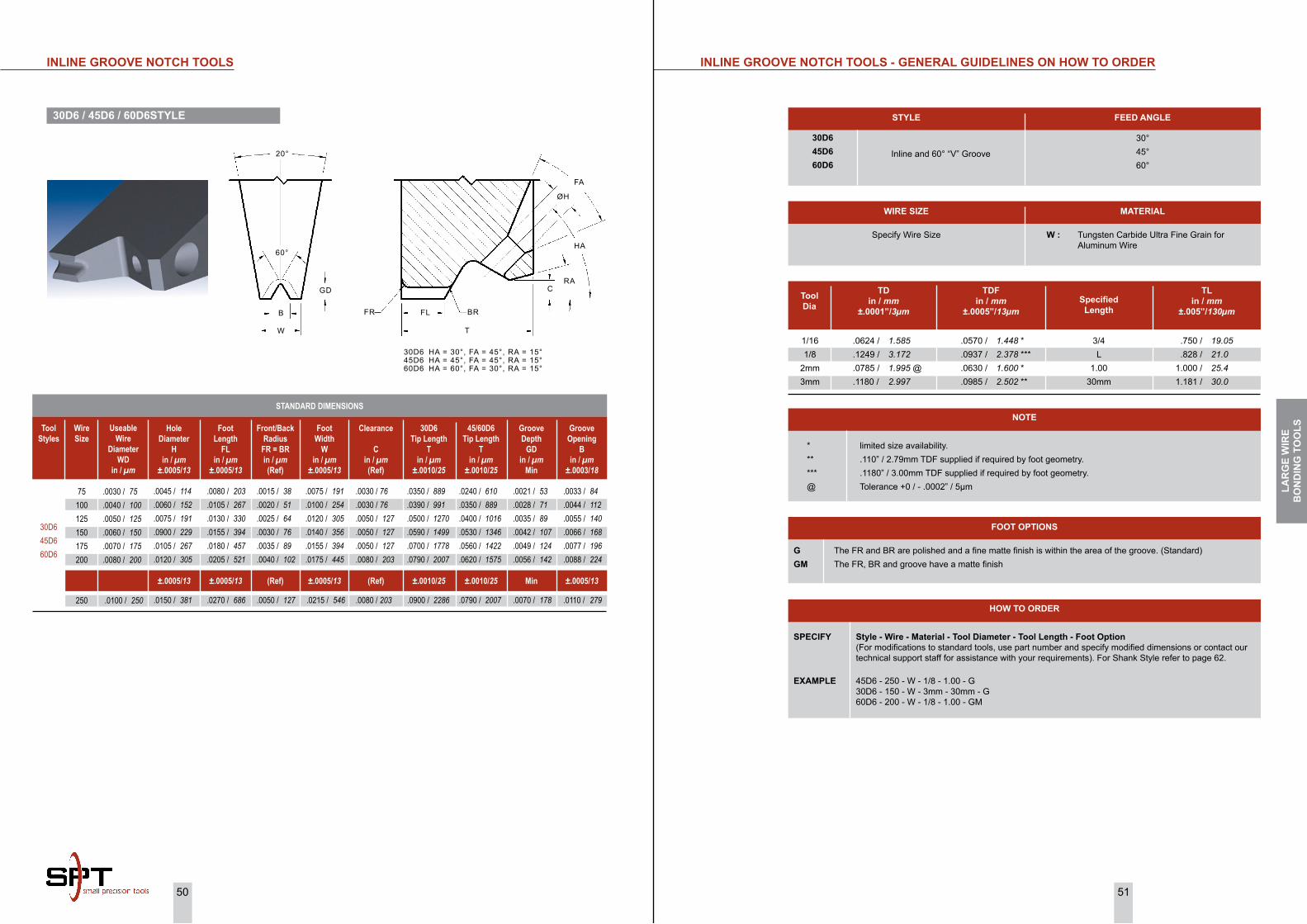
50 51
30D645D660D6
iNLiNE GRooVE NoTCh TooLS - GENERAL GUiDELiNES oN hoW To oRDER
STyLE FEED ANGLE
30°45°60°
30D645D660D6
SPECiFy Style - Wire - Material - Tool Diameter - Tool Length - Foot option (For modifications to standard tools, use part number and specify modified dimensions or contact our technical support staff for assistance with your requirements). For Shank Style refer to page 62.
EXAMPLE 45D6 - 250 - W - 1/8 - 1.00 - G 30D6 - 150 - W - 3mm - 30mm - G 60D6 - 200 - W - 1/8 - 1.00 - GM
hoW To oRDER
MATERiAL
W : Tungsten Carbide Ultra Fine Grain for Aluminum Wire
Specify Wire Size
WiRE SizE
Inline and 60° “V” Groove
G The FR and BR are polished and a fine matte finish is within the area of the groove. (Standard)GM The FR, BR and groove have a matte finish
FooT oPTioNS
1/161/8
2mm3mm
.0624 / 1.585 .1249 / 3.172 .0785 / 1.995 @ .1180 / 2.997
.0570 / 1.448 * .0937 / 2.378 *** .0630 / 1.600 * .0985 / 2.502 **
3/4L
1.0030mm
.750 / 19.05 .828 / 21.0 1.000 / 25.4 1.181 / 30.0
Tool Dia
TD in / mm
±.0001”/3µmSpecified
Length
TDFin / mm
±.0005”/13µm
TLin / mm
±.005”/130µm
* limited size availability.** .110” / 2.79mm TDF supplied if required by foot geometry.*** .1180” / 3.00mm TDF supplied if required by foot geometry.@ Tolerance +0 / - .0002” / 5µm
NoTE
30D6 / 45D6 / 60D6STyLE
75100125150175200
.0030 / 75 .0040 / 100 .0050 / 125 .0060 / 150 .0070 / 175 .0080 / 200
.0030 / 76 .0030 / 76 .0050 / 127 .0050 / 127 .0050 / 127 .0080 / 203
.0075 / 191 .0100 / 254 .0120 / 305 .0140 / 356 .0155 / 394 .0175 / 445
.0015 / 38 .0020 / 51 .0025 / 64 .0030 / 76 .0035 / 89 .0040 / 102
.0080 / 203 .0105 / 267 .0130 / 330 .0155 / 394 .0180 / 457 .0205 / 521
.0045 / 114 .0060 / 152 .0075 / 191 .0900 / 229 .0105 / 267 .0120 / 305
.0350 / 889 .0390 / 991 .0500 / 1270 .0590 / 1499 .0700 / 1778 .0790 / 2007
.0021 / 53 .0028 / 71 .0035 / 89 .0042 / 107 .0049 / 124 .0056 / 142
.0240 / 610 .0350 / 889 .0400 / 1016 .0530 / 1346 .0560 / 1422 .0620 / 1575
Hole Diameter
Hin / µm
±.0005/13
Wire Size
Groove Opening
Bin / µm
±.0003/18
Clearance
Cin / µm(Ref)
Foot Width
Win / µm
±.0005/13
Front/Back Radius
FR = BRin / µm(Ref)
Foot Length
FLin / µm
±.0005/13
Useable Wire
DiameterWD
in / µm
30D6Tip Length
Tin / µm
±.0010/25
Groove Depth
GDin / µm
Min
45/60D6Tip Length
Tin / µm
±.0010/25
±.0005/13 ±.0005/13(Ref)±.0005/13(Ref)±.0005/13 ±.0010/25 Min±.0010/25
.0033 / 84 .0044 / 112 .0055 / 140 .0066 / 168 .0077 / 196 .0088 / 224
.0100 / 250 .0080 / 203 .0215 / 546 .0050 / 127 .0270 / 686 .0150 / 381 .0900 / 2286 .0070 / 178 .0790 / 2007 .0110 / 279
iNLiNE GRooVE NoTCh TooLS
250
Tool Styles
STANDARD DIMENSIONS
FA
ØH
HA
RA
BR
C
T
FLFRB
GD
60°
W
20°
30D6 HA = 30°, FA = 45°, RA = 15°45D6 HA = 45°, FA = 45°, RA = 15°60D6 HA = 60°, FA = 30°, RA = 15°
LAR
GE
WiR
E B
oN
DiN
G T
oo
LS

52 53
* limited size availability.** .110” / 2.79mm TDF supplied if required by foot geometry.*** .1180” / 3.00mm TDF supplied if required by foot geometry.@ Tolerance +0 / - .0002” / 5µm
NoTE
1/161/8
2mm3mm
.0624 / 1.585 .1249 / 3.172 .0785 / 1.995 @ .1180 / 2.997
.0570 / 1.448 * .0937 / 2.378 *** .0630 / 1.600 * .0985 / 2.502 **
3/4L
1.0030mm
.750 / 19.05 .828 / 21.0 1.000 / 25.4 1.181 / 30.0
Tool Dia
TD in / mm
±.0001”/3µmSpecified
Length
TDFin / mm
±.0005”/13µm
TLin / mm
±.005”/130µm
iNLiNE GRooVE AUToBoNDiNG TooLS - GENERAL GUiDELiNES oN hoW To oRDER
STyLE FEED ANGLE
45°60° wire feed available with slimline
AB16
SPECiFy Style - Wire / Foot Size - Material - Tool Diameter - Tool Length - Foot option (For modifications to standard tools, use part number and specify modified dimensions or contact our technical support staff for assistance with your requirements). For Shank Style refer to page 62.
EXAMPLE AB16 - 5R - W - 3mm - L - GM AB16 - 8L - W - 1/8 - L - G
hoW To oRDER
MATERiAL
W : Tungsten Carbide Ultra Fine Grain for Aluminum Wire
Specify Wire Size
WiRE SizE
Inline and 60° “V” Groove
G The FR and BR are polished and a fine matte finish is within the area of the groove. (Standard)GM The FR, BR and groove have a matte finish
FooT oPTioNS
iNLiNE GRooVE AUToBoNDiNG TooLS
AB16 STyLE
AB16-3XSAB16-3SAB16-3RAB16-3LAB16-4SAB16-4RAB16-4LAB16-5SAB16-5RAB16-5LAB16-8SAB16-8RAB16-8L
.0030 / 75 .0030 / 75 .0030 / 75 .0030 / 75 .0040 / 100 .0040 / 100 .0040 / 100 .0050 / 125 .0050 / 125 .0050 / 125 .0080 / 200 .0080 / 200 .0080 / 200
.0033 / 84 .0033 / 84 .0033 / 84 .0033 / 84 .0044 / 112 .0044 / 112 .0044 / 112 .0055 / 140 .0055 / 140 .0055 / 140 .0088 / 224 .0088 / 224 .0088 / 224
.0015 / 38 .0025 / 64 .0035 / 89 .0045 / 114 .0030 / 76 .0050 / 127 .0060 / 152 .0040 / 102 .0060 / 152 .0075 / 191 .0065 / 165 .0095 / 241 .0120 / 305
.0036 / 91 .0036 / 91 .0036 / 91 .0036 / 91 .0048 / 122 .0048 / 122 .0048 / 122 .0060 / 152 .0060 / 152 .0060 / 152 .0096 / 244 .0096 / 244 .0096 / 244
.0024 / 61 .0024 / 61 .0024 / 61 .0024 / 61 .0032 / 81 .0032 / 81 .0032 / 81 .0040 / 102 .0040 / 102 .0040 / 102 .0064 / 163 .0064 / 163 .0064 / 163
.0039 / 99 .0049 / 124 .0059 / 150 .0069 / 175 .0064 / 163 .0084 / 213 .0094 / 239 .0080 / 203 .0100 / 254 .0115 / 292 .0130 / 330 .0160 / 406 .0185 / 470
.0055 / 140 .0055 / 140 .0055 / 140 .0055 / 140 .0070 / 178 .0070 / 178 .0070 / 178 .0090 / 229 .0090 / 229 .0090 / 229 .0145 / 368 .0145 / 368 .0145 / 368
.0075 / 191 .0075 / 191 .0075 / 191 .0075 / 191 .0100 / 254 .0100 / 254 .0100 / 254 .0125 / 318 .0125 / 318 .0125 / 318 .0200 / 508 .0200 / 508 .0200 / 508
.0015 / 38 .0015 / 38 .0015 / 38 .0015 / 38 .0020 / 51 .0020 / 51 .0020 / 51 .0025 / 64 .0025 / 64 .0025 / 64 .0040 / 102 .0040 / 102 .0040 / 102
Foot Length
FLin / µm
±.0005/13
Hole Diameter
Hin / µm
±.0005/13
Tool Styles - Wire Size / Foot Size
Groove Opening
Bin / µm
±.0005/13
Flat
Fin / µm(Ref)
Back Radius
BRin / µm
±.0005/13
Front Radius
FRin / µm
±.0005/13
Useable Wire Diameter
WDin / µm
Foot Width
Win / µm
±.0005/13
Groove Depth
GDin / µm
±.0002/5
±.0005/13±.0005/13 ±.0006/15(Ref)±.0010/25±.0010/25 ±.0010/25 ±.0003/8
AB16-10SAB16-10RAB16-10L
.0100 / 250 .0100 / 250 .0100 / 250
.0110 / 279 .0110 / 279 .0110 / 279
.0080 / 203 .0120 / 305 .0150 / 381
.0120 / 305 .0120 / 305 .0120 / 305
.0080 / 203 .0080 / 203 .0080 / 203
.0160 / 406 .0200 / 508 .0230 / 584
.0180 / 457 .0180 / 457 .0180 / 457
.0080 / 203 .0120 / 305 .0150 / 381
.0050 / 127 .0050 / 127 .0050 / 127
.0220 / 559 .0230 / 584 .0240 / 610 .0250 / 635 .0300 / 762 .0320 / 813 .0330 / 838 .0380 / 965 .0400 / 1016 .0410 / 1041 .0610 / 1549 .0640 / 1626 .0670 / 1702
Tip Length
Tin / µm
±.0010/25
±.0010/25
.0760 / 1930 .0800 / 2032 .0830 / 2108
STANDARD DIMENSIONS
ØH
45°
T
FFL
B
GD
20°
W
45°
60°
FR BR
LAR
GE
WiR
E B
oN
DiN
G T
oo
LS

SiNGLE PoiNT-TAB BoNDiNG TooLS
Nearly every desktop computer and server in use today contains one or more hard-disk drives. Every mainframe and supercomputer is normally connected to hundreds of them. You can even find VCR-type devices, portable music players such as MP3 devices, and camcorders that use Hard disks instead of tape. These billions of hard disks do one thing well-they store changing digital information in a relatively permanent form. They give computers the ability to remember things when the power goes out.
Advancement in Technology has lead to the increase in the storage capacity of the hard disk drive. The evolution towards a smaller slider has challenged the head-gimbal assembly (HGA), and head stack assembly (HSA) processes for new bonding techniques.
Flexible traces are rapidly replacing wires in the disk drive industry. These traces can be bonded with various tip designs. These bonding tools have been develop by SPT, by using a new innovative molding process to ensure tip to tip repeatability.
The most common tip configuration is the waffle tip design when using molded ceramic material. The groove or protruding (+) or (X) design when using polycrystalline diamond (PCD) tip.
Advantage of using the waffle tool design is for maximizing the transfer of ultrasonic energy during bonding where optimum bonding conditions are not present. In addition, the tool is designed with a 4-sided radius edges for orientation Flexibility. The Shank can be designed to fit wedge or Capillary transducers.
SiNGLE PoiNT-TAB BoNDiNG TooLS
SQUARE WAFFLE FooT
RoUND WAFFLE FooT
DoUBLE CRoSS GRooVE 7000 STyLE
DoUBLE CRoSS GRooVE 7100 STyLE
WiRE iMPRESSioN
SiN
GLE
Po
iNT
TAB
Bo
ND
iNG
To
oLS
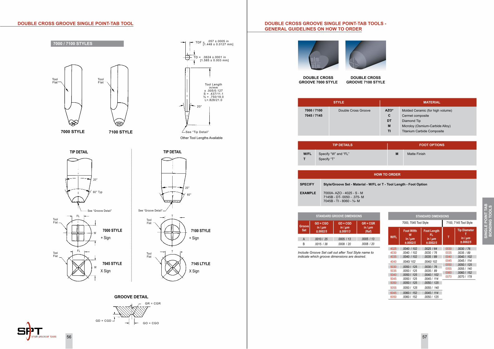
56 57
DoUBLE CRoSS GRooVE SiNGLE PoiNT-TAB TooLS - GENERAL GUiDELiNES oN hoW To oRDER
Groove Set
GO = CGOin / µm
±.0002/5
AB
.0010 / 25
.0015 /38
GD = CGDin / µm
±.0001/3
.0005 /13
.0008 /20
GR = CGRin / µm(Ref)
.0005 /13
.0008 /20
STANDARD GROOVE DIMENSIONS
Include Groove Set call out after Tool Style name to indicate which groove dimensions are desired.
.0040 /102
.0040 /102
.0040 /102
.0040 /102
.0050 / 125
.0050 / 125
.0050 / 125
.0050 / 125
.0050 / 125
.0050 / 125
.0060 / 152
.0060 / 152
402540304035404050305035504050455050505560456050
Foot WifthW
in / µm±.0002/5
7000, 7045 Tool Style
W/FL
.0025 /64
.0030 / 76
.0035 / 89
.0040 / 102
.0030 / 76
.0035 / 89
.0040 / 102
.0045 / 114
.0050 / 125
.0055 / 140
.0045 / 114
.0050 / 125
Foot LengthFL
in / µm±.0002/5
.0030 / 76
.0035 / 89
.0040 / 102
.0045 / 114
.0050 / 125
.0055 / 140
.0060 / 152
.0070 / 178
Tip DiameterT
in / µm±.0002/5
00300035004000450050005500600070
T
7100, 7145 Tool Style
STyLE MATERiAL
Molded Ceramic (for high volume)Cermet composite Diamond TipMicroloy (Osmium-Carbide Alloy)Titanium Carbide Composite
7000 / 71007045 / 7145
Double Cross Groove
FooT oPTioNS
M Matte FinishW/FL Specify “W” and “FL”T Specify “T”
TiP DETAiLS
Azo*C
DTMTi
DoUBLE CRoSS GRooVE 7000 STyLE
DoUBLE CRoSS GRooVE 7100 STyLE
SPECiFy Style/Groove Set - Material - W/FL or T - Tool Length - Foot option
EXAMPLE 7000A- AZO - 4025 - S - M 7145B - DT- 0050 - .375- M 7045B - TI - 8060 - ¾- M
hoW To oRDER
STANDARD DIMENSIONS
7000 STyLE 7100 STyLE
ToolFlat
ToolFlat
Other Tool Lengths Available
Tool Lengthin/mm
± .005/0.127S = .437/11.1¾ = .750/19.0L=.828/21.0
20°
See “Tip Detail”
.0624 ±.0001 in[1.585 ± 0.003 mm]
TD =
.057 ±.0005 in[1.448 ± 0.0127 mm]TDF =
GD = CGDGO = CGO
GR = CGR
GRooVE DETAiL
TIP DETAIL TIP DETAIL
20°
60°T
7100 STYLE+ Sign
7145 LTYLEX Sign
See “Groove Detail”
ToolFlat
ToolFlat
T
T
20°
60° Typ
See “Groove Detail”
FL
W
FL
W
7000 STYLE+ Sign
7045 STYLEX Sign
ToolFlat
ToolFlat
7000 / 7100 STyLES
DoUBLE CRoSS GRooVE SiNGLE PoiNT-TAB TooL
SiN
GLE
Po
iNT
TAB
Bo
ND
iNG
To
oLS

58 59
DoUBLE CRoSS PRoTRUSioN SiNGLE PoiNT-TAB TooLS - GENERAL GUiDELiNES oN hoW To oRDER
PeakShape
PWin / µm
±.0002/5
60° `v’60° `v’RadiusRadius
.0005 /13
.0008 /20
.0006 /15
.0010 /25
PDin / µm
±.0001/3
.0025 /6
.0005 /13
.0003 /8
.0005 /13
PRin / µm(Ref)
.0002 /5
.0002 /5
.0003 /8
.0005 /13
STANDARD PEAK DIMENSIONS
Include Peak Set call out after Tool Style name to indicate Groove dimensions.
.0040 / 102
.0040 / 102
.0060 / 152
.0060 / 152
.0060 / 152
.0060 / 152
.0080 / 203
.0080 / 203
.0080 / 203
.0080 / 203
4035404060356040605060608040805080608070
Foot WifthW
in / µm±.0002/5
7500, 7545 Tool Style
W/FL
.0035 / 89
.0040 / 102
.0035 / 89
.0040 / 102
.0050 / 125
.0060 / 152
.0040 / 102
.0050 / 125
.0060 / 152
.0070 / 178
Foot LengthFL
in / µm±.0002/5
.0030 / 76
.0035 / 89
.0040 / 102
.0050 / 125
.0055 / 140
.0060 / 152
.0070 / 178
Tip DiameterT
in / µm±.0002/5
0030003500400050005500600070
T
7600, 7645 Tool StylePeakSet
ABCD
SPECiFy Style/Peak Set - Material - W/FL or T - Tool Length - Foot option
EXAMPLE 7500A - AZO - 4025 - S - M 7545B - DT - 8060 - .375 - M 7645B - TI - 0060 - 3/4 - M
hoW To oRDER
7500 / 76007545 / 7645
Double Cross Protrusion
STyLE MATERiAL
STANDARD DIMENSIONS
FooT oPTioNS
M Matte FinishW/FL Specify “W” and “FL”T Specify “T”
TiP DETAiLS
Azo*C
DTMTi
Molded Ceramic (for high volume)Cermet composite Diamond TipMicroloy (Osmium-Carbide Alloy)Titanium Carbide Composite
7500 / 7600 STyLES
DoUBLE CRoSS PRoTRUSioN SiNGLE PoiNT-TAB TooL
Other Tool Lengths Available
Tool Lengthin/mm
± .005/0.127S = .437/11.1¾ = .750/19.0L=.828/21.0
20°
See “Tip Detail”
.0624 ±.0001 in[1.585 ± 0.003 mm]
TD =
.057 ±.0005 in[1.448 ± 0.0127 mm]TDF =
7500 STYLE
TIP DETAIL TIP DETAIL
20°
60°T
T
7645 STYLEX Sign
7600 STYLE+ Sign
See “Peak Details”
ToolFlat
ToolFlat
T
20°
60° Typ
See “Peak Details”
FL
W
FL
W
7545 STYLEX Sign
7500 STYLE+ Sign
ToolFlat
ToolFlat
7600 STYLE
ToolFlat
ToolFlat
PDPW
PR
Peak DETAiL
60°
PDPW
PR
A, B Peak Set C, D Peak Set
DoUBLE CRoSS PRoTRUSioN 7500/7600”
SiN
GLE
Po
iNT
TAB
Bo
ND
iNG
To
oLS

60 61
WAFFLE FooT SiNGLE PoiNT-TAB TooLS - GENERAL GUiDELiNES oN hoW To oRDER
Foot WifthW
in / µm±.0002/5
7045 Tool Style
W/FL
Foot LengthFL
in / µm±.0002/5
Tip DiameterT
in / µm±.0002/5
T
7145 Tool Style
Flat Orientaion
SQUARE WAFFLE FooT 7045W STyLE
RoUND WAFFLE FooT7145W STyLE
SPECiFy Style - Material - W/FL or T - Tool Length - Foot Finish - Flat orientation
EXAMPLE 7145W - AZO - 0050 - .375 - M - (Reference Page 60) 7045W - DT- 8070 - ¾- M - (Reference Page 60)
hoW To oRDER
7045W / 7145W Waffle Tip
STyLE MATERiAL
STANDARD DIMENSIONS
FooT oPTioNS
M Matte FinishW/FL Specify “W” and “FL”T Specify “T”
TiP DETAiLS
.0050 /127
.0069 / 175
.0070 / 178
.0073 / 185
.0074 / 188
.0080 / 203
.0080 / 203
.0090 / 229
50556949708073607474807080909060
.0055 / 140
.0049 / 124
.0080 / 203
.0060 / 152
.0074 / 188
.0070 / 178
.0090 / 229
.0060 / 152
.0050 / 125
.0055 / 140
.0060 / 152
.0070 / 178
.0075 / 191
0050*0055006000700075
See ChartSee ChartSee ChartSee ChartSee Chart
Shank Style
See Page 60See Page 60See Page 60See Page 60See Page 60See Page 60See Page 60See Page 60
Azo*C
DTM
Molded Ceramic (for high volume)Cermet composite Diamond TipMicroloy (Osmium-Carbide Alloy)
7045W / 7145W STyLES
WAFFLE FooT SiNGLE PoiNT-TAB TooLS
Tool Flat
Tool Flat
7045W STyLE 7145W STyLEOther Tool Lengths Available
Tool Lengthin/mm
± .005/0.127S = .437/11.1¾ = .750/19.0L=.828/21.0
20°
See “Tip Detail”
.0624 ±.0001 in[1.585 ± 0.003 mm]
TD =
.057 ±.0005 in[1.448 ± 0.0127 mm]TDF =
45° Typ
FL
W
7045W STYLE
30° MTA
Varies
30°MTA
50°
7145W STYLE
T
45°
R = .0001 in [0.003 mm](REF) Typ
.0008±.0001 in[0.020±0.003 mm]
.0003±.00005 in[0.008±0.0013 mm]
.0005±.0001 in[0.013±0.003 mm]
TYPICAL GROOVE DETAIL
GA = 60°
SiN
GLE
Po
iNT
TAB
Bo
ND
iNG
To
oLS
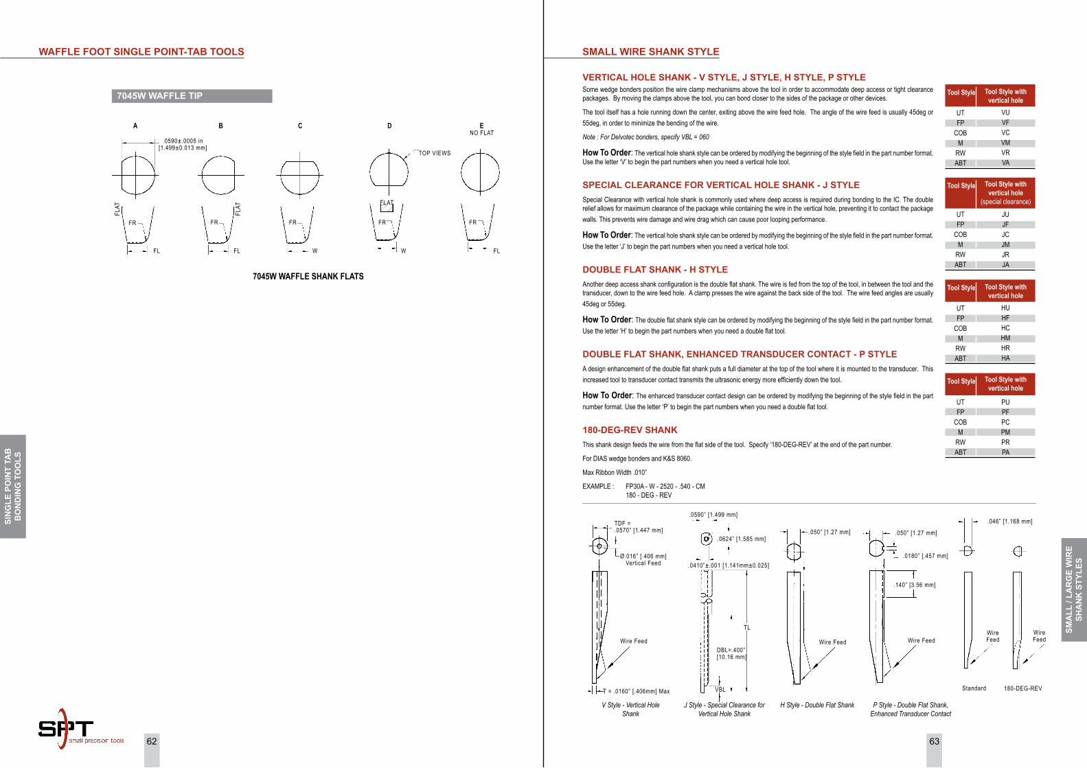
62 63
SMALL WiRE ShANK STyLE
TDF = .0570” [1.447 mm]
T = .0160” [.406mm] Max
Wire Feed
Ø.016” [.406 mm]Vertical Feed
.050” [1.27 mm]
.140” [3.56 mm]
.050” [1.27 mm]
.0180” [.457 mm]
Wire FeedWire Feed
.0590” [1.499 mm]
.0624” [1.585 mm]
.0410”±.001 [1.141mm±0.025]
VBL
TL
DBL=.400” [10.16 mm]
Tool Style
Tool Style with vertical hole
VUVFVCVMVRVA
UTFP
COBM
RWABT
HUHFHCHMHRHA
UTFP
COBM
RWABT
PUPFPCPMPRPA
UTFP
COBM
RWABT
Tool Style Tool Style with vertical hole
(special clearance)
JUJFJCJMJRJA
Wire Feed
Wire Feed
Standard 180-DEG-REV
.046” [1.168 mm]
UTFP
COBM
RWABT
VERTiCAL hoLE ShANK - V STyLE, J STyLE, h STyLE, P STyLESome wedge bonders position the wire clamp mechanisms above the tool in order to accommodate deep access or tight clearance packages. By moving the clamps above the tool, you can bond closer to the sides of the package or other devices.
The tool itself has a hole running down the center, exiting above the wire feed hole. The angle of the wire feed is usually 45deg or 55deg, in order to minimize the bending of the wire.
Note:ForDelvotecbonders,specifyVBL=060
How To Order: The vertical hole shank style can be ordered by modifying the beginning of the style field in the part number format. Use the letter ‘V’ to begin the part numbers when you need a vertical hole tool.
SPECiAL CLEARANCE FoR VERTiCAL hoLE ShANK - J STyLESpecial Clearance with vertical hole shank is commonly used where deep access is required during bonding to the IC. The double relief allows for maximum clearance of the package while containing the wire in the vertical hole, preventing it to contact the package walls. This prevents wire damage and wire drag which can cause poor looping performance.
How To Order: The vertical hole shank style can be ordered by modifying the beginning of the style field in the part number format. Use the letter ‘J’ to begin the part numbers when you need a vertical hole tool.
DoUBLE FLAT ShANK - h STyLEAnother deep access shank configuration is the double flat shank. The wire is fed from the top of the tool, in between the tool and the transducer, down to the wire feed hole. A clamp presses the wire against the back side of the tool. The wire feed angles are usually 45deg or 55deg.
How To Order: The double flat shank style can be ordered by modifying the beginning of the style field in the part number format. Use the letter ‘H’ to begin the part numbers when you need a double flat tool.
DoUBLE FLAT ShANK, ENhANCED TRANSDUCER CoNTACT - P STyLEA design enhancement of the double flat shank puts a full diameter at the top of the tool where it is mounted to the transducer. This increased tool to transducer contact transmits the ultrasonic energy more efficiently down the tool.
How To Order: The enhanced transducer contact design can be ordered by modifying the beginning of the style field in the part number format. Use the letter ‘P’ to begin the part numbers when you need a double flat tool.
180-DEG-REV ShANKThis shank design feeds the wire from the flat side of the tool. Specify ‘180-DEG-REV’ at the end of the part number.
For DIAS wedge bonders and K&S 8060.
Max Ribbon Width .010”
EXAMPLE : FP30A - W - 2520 - .540 - CM 180 - DEG - REV
VStyle-VerticalHoleShank
PStyle-DoubleFlatShank,EnhancedTransducerContact
HStyle-DoubleFlatShankJStyle-SpecialClearanceforVerticalHoleShank
Tool Style
Tool Style with vertical hole
Tool Style Tool Style with vertical hole
7045W WAFFLE TiP
WAFFLE FooT SiNGLE PoiNT-TAB TooLS
7045W WAFFLE SHANK FLATS
.0590±.0005 in[1.499±0.013 mm]
A B C D ENO FLAT
FR
FL
FLAT
FR
FL
FLAT
FR
W
FR
W
FLAT
FR
FL
TOP VIEWS
SMA
LL /
LAR
GE
WiR
ESh
AN
K S
TyLE
S
SiN
GLE
Po
iNT
TAB
Bo
ND
iNG
To
oLS

64 65
TiP To ShANK RATioSLARGE WiRE ShANK STyLES
TiP To ShANK RATioS
When selecting a wedge,
* The amplitude of the tools vibration at its foot is a ratio of the input (shank) diameter to the output (foot) diameter..
* Bonding wedges are designed with varying tip-to shank dimensional ratios.
* The smaller the tip the higher the amplitude which will rapidly dampen in contact with the bond surface.
* As the tip grows with the same input amplitude, will vibrate at a comparatively lower amplitude but dampens more slowly, presenting the hazards of over-working the bond.
* In general, larger wire requires more energy to bond than small wire.
* Stiffer wedges works best as wire size increases.
Dia. Dia.Input
T TOutput
Amplitude high
Amplitude Low
30D645D660D6
45153015451630161015A2015A1016A2016A
10°
TDF
TD
10° Typ
20° as required by tool size
LW15LW16
0.064” [1.63mm]
10° Typ
20° as required by tool size
E
20°
LWD6CKVD
Shank Style“B” = 10°“C” = 20°(Optional)
Shank Style A
E
Shank Style Bin 2mm only
AB1645CK1010A2010A1009A
10° Typ
20° as required by tool size
TDF
TD
Back angle varies with wire size
5°
FR BR
OSG7
10°
10°
CK
.062” [1.60mm Typ]
Shank Style A{Standard)
Shank Style B(Optional)
in 2mm only
Shank Style A used unless specified at end of a part number
Shank Style A used unless specified at end of a part number
SMA
LL /
LAR
GE
WiR
ESh
AN
K S
TyLE
S

66 6767
NoTES :
Customer :
Department :
Company :
Date : / /
Contact No : Extn :
Order taken by :
Application :
Lead Count :
Wire Diameter : Material :
Bonder / Model :
Bond Pad Size :
Pad Pitch :
Loop Height (target) :
Deformed Bond Width :
Bond Pad Metallization :
Distance between Pad to Lead :
Lead Width :
Lead Pitch :
Lead Metallization :
Bonding Temperature :
Ultrasonic Bonding Frequency :
Present Wedge Part Number(s) :
Wire Bonding Top 3 Defects :
Any Other Wire Bonding problems?
Recommended SPT Wedge Part No:
ULTRASoNiC Bonding WEDGES Requirement Checklist
SPT Roth LtdFax : +41 32 387 80 88
Small Precision Tools IncFax : +1 707 778 2271
SPT Asia Pte. Ltd.Fax : +65 6250 2725
Small Precision Tools (Phil.) Corp.Fax : +632 531-5780
Small Precision Tools Co. Ltd.Fax : +86-510-8516 5233
SPT Japan Co., Ltd.Fax : +81-45-470-6755
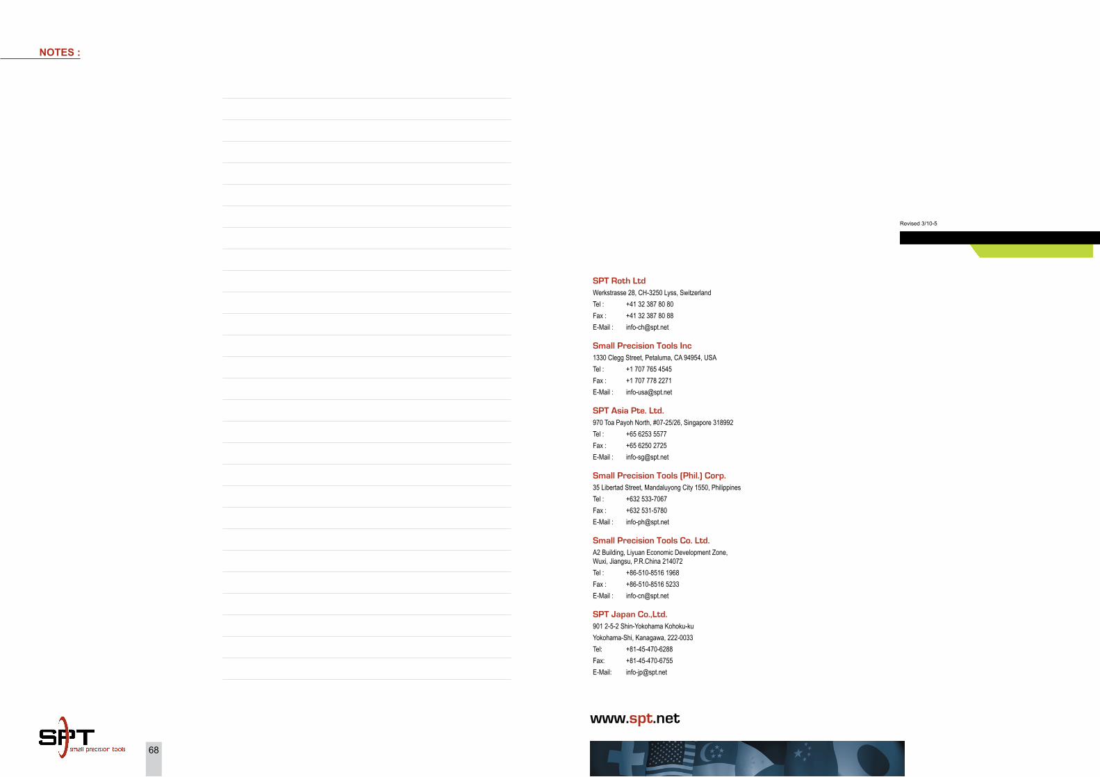
68
NoTES :
68
Revised 3/10-5
SPT Roth LtdWerkstrasse 28, CH-3250 Lyss, SwitzerlandTel : +41 32 387 80 80 Fax : +41 32 387 80 88E-Mail : [email protected]
Small Precision Tools Inc1330 Clegg Street, Petaluma, CA 94954, USATel : +1 707 765 4545 Fax : +1 707 778 2271 E-Mail : [email protected]
SPT Asia Pte. Ltd.970 Toa Payoh North, #07-25/26, Singapore 318992Tel : +65 6253 5577Fax : +65 6250 2725E-Mail : [email protected]
Small Precision Tools (Phil.) Corp.35 Libertad Street, Mandaluyong City 1550, PhilippinesTel : +632 533-7067Fax : +632 531-5780E-Mail : [email protected]
Small Precision Tools Co. Ltd.A2 Building, Liyuan Economic Development Zone, Wuxi, Jiangsu, P.R.China 214072Tel : +86-510-8516 1968Fax : +86-510-8516 5233E-Mail : [email protected]
SPT Japan Co.,Ltd.901 2-5-2 Shin-Yokohama Kohoku-kuYokohama-Shi, Kanagawa, 222-0033Tel: +81-45-470-6288Fax: +81-45-470-6755E-Mail: [email protected]
www.spt.net


![Realistic Soft Shadows by Penumbra-Wedges Blending · Penumbra-wedges X + Specular & diffuse Visibility buffer Modulated spec+diff Ambient Final image. Penumbra-wedges [3/4] Penumbra-wedges](https://img.pdfslide.us/doc/110x75/5f543a4c0135c76e2b226697/realistic-soft-shadows-by-penumbra-wedges-penumbra-wedges-x-specular-diffuse.jpg)