Embed Size (px)
Citation preview
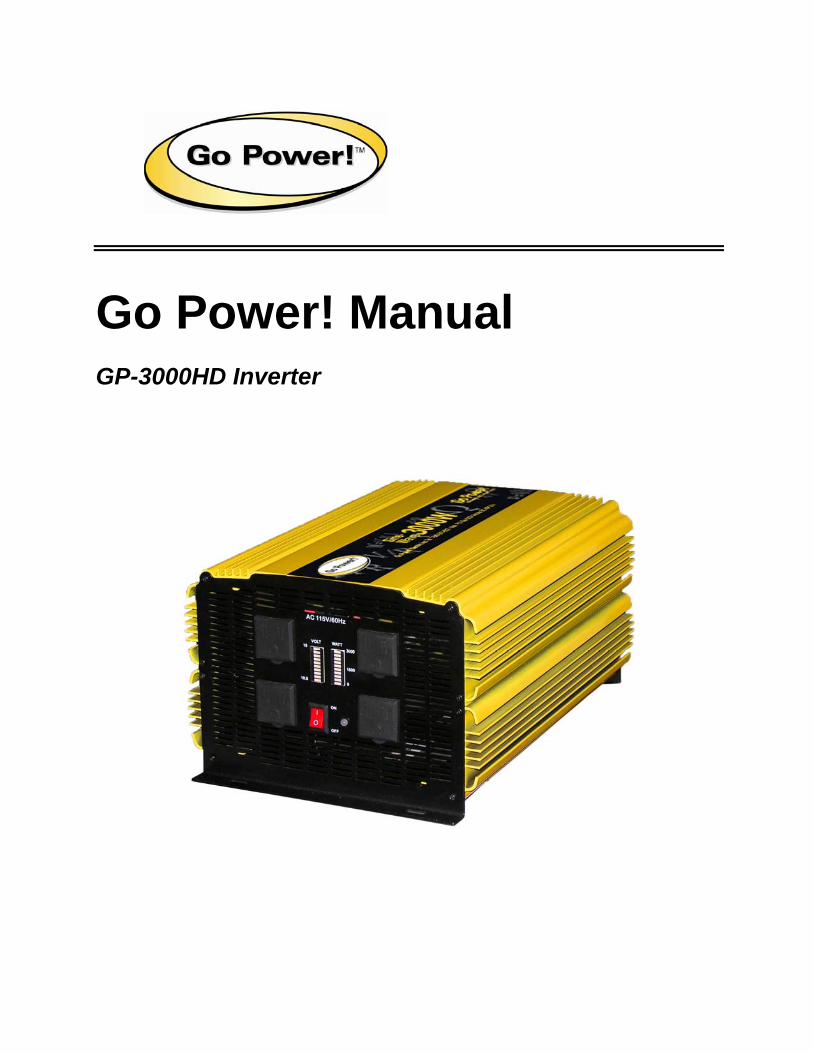
Go Power! Manual
GP-3000HD Inverter
Go Power! Modified Sine Wave InverterOwner’s Manual
www.gpelectric.com 2
Contents
1.0 Introduction 4
2.0 Specifications 5 2.1 GP-3000HD Inverter ...........................................................................5
3.0 Features 6 3.1 Front View – GP-3000HD ...................................................................6
3.2 Rear View – GP-3000HD ....................................................................7
4.0 Installation 8 4.1 Where to Install ..................................................................................8
4.2 Connecting and Testing ....................................................................8
4.3 DC Install Kits.....................................................................................9
4.4 Cables ...............................................................................................10
4.5 Inverter Fuse ....................................................................................10
4.6 Grounding.........................................................................................10
5.0 Operation 12 5.1 Controls and Indicators...................................................................12
5.2 Optional On / Off Remote ................................................................12
5.3 Battery Voltage Indicator.................................................................12
5.4 Battery Current Indicator.................................................................12
5.5 Power Output....................................................................................12
5.6 Input Voltage ....................................................................................13
6.0 Troubleshooting 14 6.1 Common Problems ..........................................................................14
6.2 Troubleshooting Guide....................................................................14
7.0 Maintenance 15
8.0 Warranty 16 8.1 Go Power! 1 Year Limited Warranty ...............................................16 8.1.1 What the Go Power! Warranty Covers and for How Long 16 8.1.2 What the Go Power! Warranty Does Not Cover 16 8.1.3 Restrictions and Limitations to the Go Power! Warranty 17
8.2 Warranty Return Procedure ............................................................17 8.2.1 End Users 17 8.2.2 Dealers 17 8.2.3 Units Bought Directly from Go Power! 18
8.3 Additional Information.....................................................................18
8.4 Out of Warranty Items......................................................................18
9.0 RV Supplement 19

Go Power! Modified Sine Wave InverterOwner’s Manual
www.gpelectric.com 3
9.1 Installing the GP-3000HD Without an Automatic Transfer Switch .19
9.2 Installing the GP-3000HD With an Automatic Transfer Switch.......19
Go Power! Modified Sine Wave InverterOwner’s Manual
www.gpelectric.com 4
1.0 Introduction
The Go Power! Inverter series provides mobile power for dependable operation of standard appliances wherever you travel. Silent, lightweight, and simple to use, Go Power! Inverters can be used in a wide range of applications including RVs, boats, and light and heavy duty truck applications. It will operate most televisions, DVD players, computers, and small appliances including drills, sanders, grinders, mixers, blenders, and microwaves.
To get the most out of your power inverter, it must be installed and used properly.
Please read the instructions in this manual before installing and using your inverter.
Go Power! Modified Sine Wave InverterOwner’s Manual
www.gpelectric.com 5
2.0 Specifications
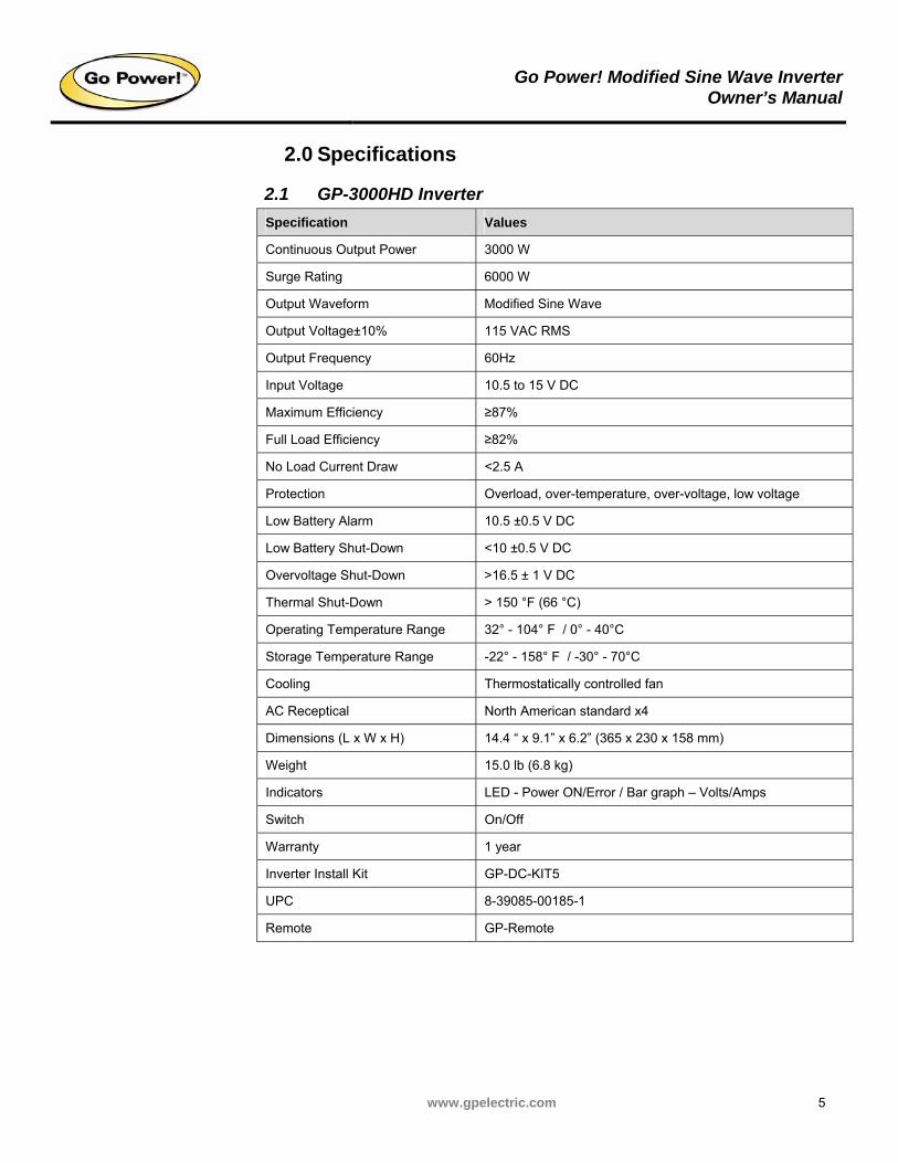
2.1 GP-3000HD Inverter
Specification Values
Continuous Output Power 3000 W
Surge Rating 6000 W
Output Waveform Modified Sine Wave
Output Voltage±10% 115 VAC RMS
Output Frequency 60Hz
Input Voltage 10.5 to 15 V DC
Maximum Efficiency ≥87%
Full Load Efficiency ≥82%
No Load Current Draw <2.5 A
Protection Overload, over-temperature, over-voltage, low voltage
Low Battery Alarm 10.5 ±0.5 V DC
Low Battery Shut-Down <10 ±0.5 V DC
Overvoltage Shut-Down >16.5 ± 1 V DC
Thermal Shut-Down > 150 °F (66 °C)
Operating Temperature Range 32° - 104° F / 0° - 40°C
Storage Temperature Range -22° - 158° F / -30° - 70°C
Cooling Thermostatically controlled fan
AC Receptical North American standard x4
Dimensions (L x W x H) 14.4 “ x 9.1” x 6.2” (365 x 230 x 158 mm)
Weight 15.0 lb (6.8 kg)
Indicators LED - Power ON/Error / Bar graph – Volts/Amps
Switch On/Off
Warranty 1 year
Inverter Install Kit GP-DC-KIT5
UPC 8-39085-00185-1
Remote GP-Remote
Go Power! Modified Sine Wave InverterOwner’s Manual
www.gpelectric.com 6
3.0 Features
3.1 Front View – GP-3000HD
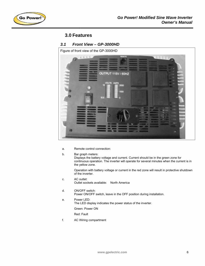
Figure of front view of the GP-3000HD
a. Remote control connection:
b. Bar graph meters: Displays the battery voltage and current. Current should be in the green zone for continuous operation. The inverter will operate for several minutes when the current is in the yellow zone.
Operation with battery voltage or current in the red zone will result in protective shutdown of the inverter.
c. AC outlet: Outlet sockets available: North America
d. ON/OFF switch: Power ON/OFF switch, leave in the OFF position during installation.
Power LED: The LED display indicates the power status of the inverter.
Green: Power ON
e.
Red: Fault
f. AC Wiring compartment
Go Power! Modified Sine Wave InverterOwner’s Manual
www.gpelectric.com 7
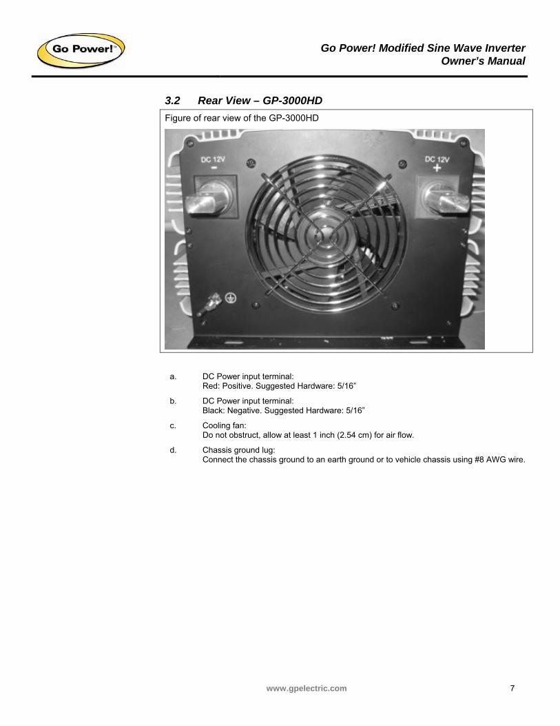
3.2 Rear View – GP-3000HD
Figure of rear view of the GP-3000HD
a. DC Power input terminal: Red: Positive. Suggested Hardware: 5/16”
b. DC Power input terminal: Black: Negative. Suggested Hardware: 5/16”
c. Cooling fan: Do not obstruct, allow at least 1 inch (2.54 cm) for air flow.
d. Chassis ground lug: Connect the chassis ground to an earth ground or to vehicle chassis using #8 AWG wire.
Go Power! Modified Sine Wave InverterOwner’s Manual
www.gpelectric.com 8
4.0 Installation
4.1 Where to Install
The power inverter should be installed in a location that meets the following requirements:
Do not connect this inverter and another AC source (generator or utility power) to the AC wiring or AC loads at the same time. Doing so will destroy the inverter and void the warranty, regardless whether the inverter is switched on or off. If you are using more than one AC source for the AC wiring or AC loads, it is highly recommended that you install an automatic transfer switch (GP-TS), available from Go Power!
a) Dry: Do not allow water to drip or splash on the inverter.
b) Cool: Ambient air temperature should be between 32 – 104 °F (0 – 40 °C).
c) Ventilated: Allow at least 2” (5 cm) of clearance around the inverter for air flow. Ensure the ventilation openings on the rear and bottom of the unit are not obstructed.
d) Safe: Do not install the inverter in the same compartment as batteries or in any compartment capable of igniting flammable liquids such as gasoline.
e) The inverter should be located within 10 ft (3 m) of the batteries.
4.2 Connecting and Testing
The following section describes how to connect and test the GP-3000HD inverters.
A reverse polarity connection will permanently damage the inverter. Damage caused by reverse polarity connection is not covered by the warranty.
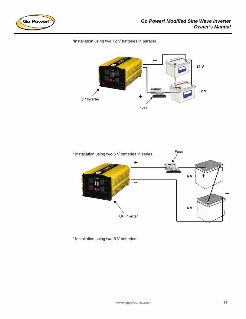
This inverter must only be connected to batteries with a nominal output voltage of 12 V. Lower voltages will not operate the inverter properly, and higher voltages could damage the inverter or the device being powered. If more than one 12 V battery is used, the batteries must be connected in a parallel circuit; batteries connected in a series circuit will produce too much voltage.
You may observe a spark when you make this connection since current may flow to charge capacitors in the power inverter. Do not make this connection in the presence of flammable fumes, as explosion or fire may result.
1. Unpack and inspect your Go Power! inverter. Ensure that the power switch is in the OFF position.
2. Install the inverters on a flat surface, ensure that it has adequate ventilation and is not in direct sunlight. Securely fasten the inverter to the surface. We recommend using GP-DC Install Kits whenever installing a GP Inverter.; see section 4.3 DC Install Kits.
Go Power! Modified Sine Wave InverterOwner’s Manual
www.gpelectric.com 9
3. When attaching the DC inverter cables to the power input terminals on the rear panel of the power inverter. The (+) terminal is positive and (-) terminal is negative. Tighten the terminal bolt or nut to clamp the wires securely. Ensure connections are tight.
4. Connect the ground cable to the appropriate location; see section 4.6 Grounding.
5. Connect the cable from the negative terminal of the inverter to the negative terminal of the battery. Make a secure connection.
Loose connections result in excessive voltage drop and may cause overheated wires and melted insulation. Ensure connections are tight.
6. Before proceeding further, carefully check that the cable you have just connected is going from the negative terminal of inverter to the negative output terminal of the power source (battery).
7. Install the inverter fuse into the positive lead. Fuse should be located within 12” (31 cm) of battery. Ensure all connections are tight and secure.
8. Connect the cable from the positive terminal of inverter to the positive terminal of the battery. Make a secure connection. Check your polarity.
This inverter cannot supply power to any AC distribution wiring or AC loads in which the neutral and ground are connected (bonded). Doing so will destroy the unit and void the warranty. If you do not understand neutral to ground bonding then please have a professional install your system for you. See “Grounding” for more information.
9. Set the power switch to the ON position. Check the meters and indicators on the front panel of the inverter. The voltage bar graph should indicate 11 to 14 V depending on the voltage of the power source. If it is does not, check your battery bank and the connections to the inverter. The other indicators should be OFF.
10. Set the power inverter switch to the OFF position. The indicator lights may blink and the internal alarm may sound momentarily. This is normal. Plug the test load into the AC receptacle on the front panel of the inverter.
11. Set the power inverter switch to the ON position and turn the test load on; the inverter should supply power to the load. If you plan to measure the output voltage of the inverter, a true RMS meter must be used for accurate readings.
4.3 DC Install Kits
Go Power! DC Installation Kits include everything you will need to properly connect your Go Power! Inverter to the batteries.
GP-3000HD – GP-DC-KIT 5
Go Power! Modified Sine Wave InverterOwner’s Manual
www.gpelectric.com 10
4.4 Cables
DC to AC inverters require high amperage to operate properly; connect inverter DC input terminals to battery with heaviest wire available; see Table 4-1.
Table 4-1: Wire Gauge
Max. Watts Out Approx. Amps Required (12 V DC) Wire Gauge*
3000 W >300 4/0
*It is recommended that the cable length not exceed 10 ft (3 m).
4.5 Inverter Fuse
A class “T” inverter fuse should be included in all installations.
GP-3000HD – 400 A fuse
4.6 Grounding
Do not install the power inverter in a positive ground DC system. A positive ground DC system has the positive terminal of the battery connected to the chassis of the vehicle or to a grounding point.
Do not operate the power inverter without connecting it to ground. Electrical shock hazard may result.
The power inverter has a lug on the rear panel: "Chassis Ground." This is to connect the chassis of the power inverter to a grounding point.
The power inverter grounding point will vary depending on where the power inverter is installed. In a vehicle, connect the chassis ground to the chassis of the vehicle. In a boat, connect to the boat's grounding systems. In a fixed location, connect the chassis ground lug to earth.
The neutral (common) conductor of the power inverter AC output circuit is not bonded to the chassis ground. Therefore, when the chassis is connected to ground, the neutral conductor will not be grounded.
At no point should the chassis ground and the neutral conductor of the inverter be bonded. Bonding the chassis ground and the neutral conductor of the inverter or connecting the inverter to household or recreational AC distribution wiring will damage the unit and void the warranty.
As per the national electrical code, electrical panels in mobile applications (boats, RVs etc.) must not have a neutral to ground bond.
Go Power! Modified Sine Wave InverterOwner’s Manual
www.gpelectric.com 11
*Installation using two 12 V batteries in parallel.
* Installation using two 6 V batteries in series.
* Installation using two 6 V batteries.
Fuse
_
Fuse
+
+
_ 12 V
6 V
12 V
6 V
+
_
GP Inverter
GP Inverter
Go Power! Modified Sine Wave InverterOwner’s Manual
www.gpelectric.com 12
5.0 Operation
To operate the power inverter, turn it on using the ON/OFF switch on the front panel. The power inverter is now ready to deliver AC power to your loads. If you are operating several loads from the power inverter, turn them on separately, one after another. This will ensure that the power inverter does not have to deliver the starting currents for all the loads at once.
5.1 Controls and Indicators
The ON/OFF switch turns the control circuit in the power inverter ON and OFF. It does not disconnect power from the power inverter.
When the switch is in the OFF position, the power inverter draws no current from the battery. When the switch is in the ON position but with no load, the power idle current is approximately 1 – 2 A (see product specifications for exact current draw).
5.2 Optional On / Off Remote
The optional remote switch (sold separately) can be used to turn the inverter on and off from a location up to 25 ft (8 m) away. The inverter should be OFF when plugging remote in. Once the remote is installed the inverter ON/OFF switch must be in the ON position.
5.3 Battery Voltage Indicator
The battery voltage bar graph indicates the voltage at the input terminals of the power inverter. At low input current, the display voltage will be very close to the battery voltage. At high input current, the display voltage will be lower than the battery voltage.
Ideally, the voltage should remain in the green areas of the bar graph. If the voltage goes into the red area at the top or bottom of the graph, the inverter may shut-down.
5.4 Battery Current Indicator
The battery current bar graph indicates the current drawn from the battery by the power inverter. It will not indicate current by other loads also connected to the battery.
For long-term operation, the current should be in the green area of the bar graph. Short-term operation is possible with current in the yellow area. If the current rises to the red area, the inverter will shut itself down and the overload indicator will light.
5.5 Power Output
The inverter will operate most AC loads within its power rating. When determining whether a microwave oven can be operated by the Power Inverter, remember that the power commonly advertised for microwave ovens is the cooking power (the power delivered to the food), not the power actually consumed by the microwave oven. The microwave oven will consume 40% to 100% more than its advertised cooking power. Check the rating sticker on the back of the oven to determine its actual power draw.
Some induction motors used in refrigerators, freezers, pumps and other motor operated equipment require very high surge currents to start. The power inverter may not be able to start some of these motors, even though their rated current draw is within the power inverter.
If the motor refuses to start, observe the battery voltage indicator while trying to start the motor. If the battery voltage indicator drops below 11 V while the inverter is attempting to start the motor, this may be why the motor will not start. Make sure that the battery connections are good and that the battery is fully charged. If the connections are good
Go Power! Modified Sine Wave InverterOwner’s Manual
www.gpelectric.com 13
and the battery is charged, but the voltage still drops below 11 V, you may need to use a larger battery.
5.6 Input Voltage
The Power Inverter will operate from input voltage ranging 10 V – 15 V. If the voltage drops below 10.7 V, an audible low battery warning will sound and the voltage indicator will be in the lower red zone. The power inverter will shut down if the input voltage drops below 10 V. This protects your battery from being over discharged.
The Power Inverter will also shut down if the input voltage exceeds 15 V. This protects the inverter against excessive input voltage. The voltage indicator will be in the upper red zone. Although the power inverter incorporates protection against overvoltage, it may still be damaged if the input voltage is allowed to exceed 20 V.
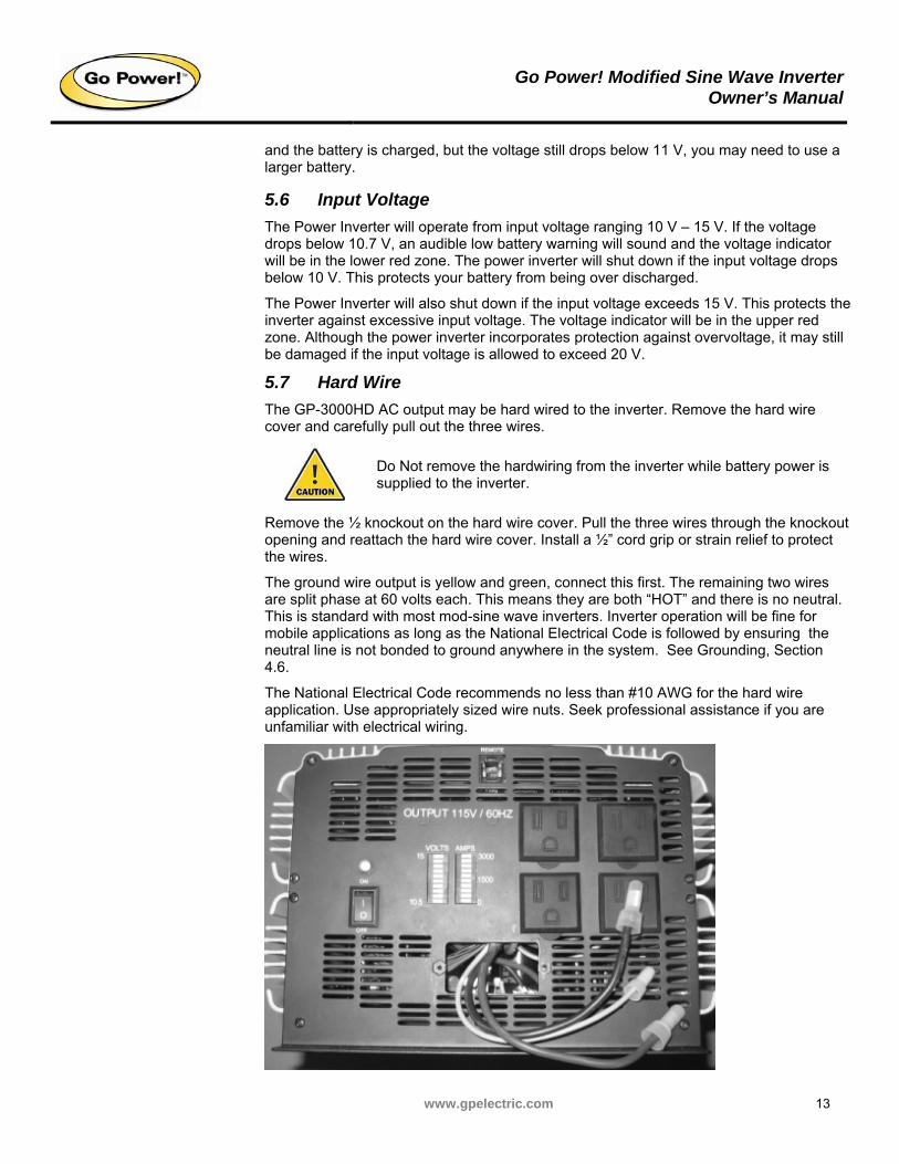
5.7 Hard Wire
The GP-3000HD AC output may be hard wired to the inverter. Remove the hard wire cover and carefully pull out the three wires.
Do Not remove the hardwiring from the inverter while battery power is supplied to the inverter.
Remove the ½ knockout on the hard wire cover. Pull the three wires through the knockout opening and reattach the hard wire cover. Install a ½” cord grip or strain relief to protect the wires.
The ground wire output is yellow and green, connect this first. The remaining two wires are split phase at 60 volts each. This means they are both “HOT” and there is no neutral. This is standard with most mod-sine wave inverters. Inverter operation will be fine for mobile applications as long as the National Electrical Code is followed by ensuring the neutral line is not bonded to ground anywhere in the system. See Grounding, Section 4.6.
The National Electrical Code recommends no less than #10 AWG for the hard wire application. Use appropriately sized wire nuts. Seek professional assistance if you are unfamiliar with electrical wiring.
Go Power! Modified Sine Wave InverterOwner’s Manual
www.gpelectric.com 14
6.0 Troubleshooting
6.1 Common Problems
Buzz in audio systems
Some inexpensive stereo systems will emit a buzzing noise from their loudspeakers when operated from the power inverter. This is due to the power supply in the device does not adequately filter the modified sine wave produced by the power inverter. The only solution is to use a sound system that incorporates a higher quality power supply.
There are audible low voltage / over load alarms on all GP inverters.
Television Interference
Operation of the power inverter can interfere with television reception on some channels. If this situation occurs, the following steps may help to alleviate the problem.
Make sure that the chassis ground lug on the back of the power inverter is solidly connected to the ground system of your vehicle, boat or home.
Do not operate high power loads with the Power Inverter while watching television.
Make sure that the antenna feeding your television provides an adequate ("snow free") signal and that you are using good quality cable between the antenna and the television.
Move the television as far away from the power inverter as possible.
Keep the cables between the battery and the power inverter as short as possible and twist them together with about 2 to 3 twists per foot. This minimizes radiated interference from the cables.
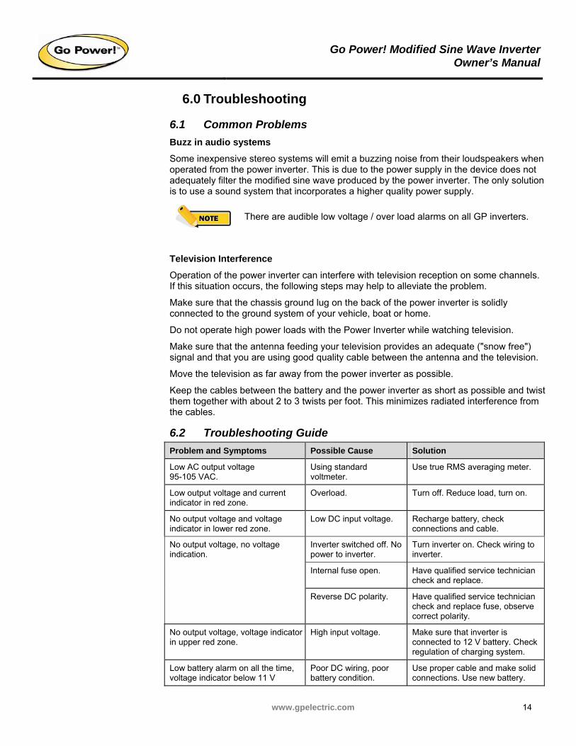
6.2 Troubleshooting Guide
Problem and Symptoms Possible Cause Solution
Low AC output voltage 95-105 VAC.
Using standard voltmeter.
Use true RMS averaging meter.
Low output voltage and current indicator in red zone.
Overload. Turn off. Reduce load, turn on.
No output voltage and voltage indicator in lower red zone.
Low DC input voltage. Recharge battery, check connections and cable.
Inverter switched off. No power to inverter.
Turn inverter on. Check wiring to inverter.
Internal fuse open. Have qualified service technician check and replace.
No output voltage, no voltage indication.
Reverse DC polarity. Have qualified service technician check and replace fuse, observe correct polarity.
No output voltage, voltage indicator in upper red zone.
High input voltage. Make sure that inverter is connected to 12 V battery. Check regulation of charging system.
Low battery alarm on all the time, voltage indicator below 11 V
Poor DC wiring, poor battery condition.
Use proper cable and make solid connections. Use new battery.
Go Power! Modified Sine Wave InverterOwner’s Manual
www.gpelectric.com 15
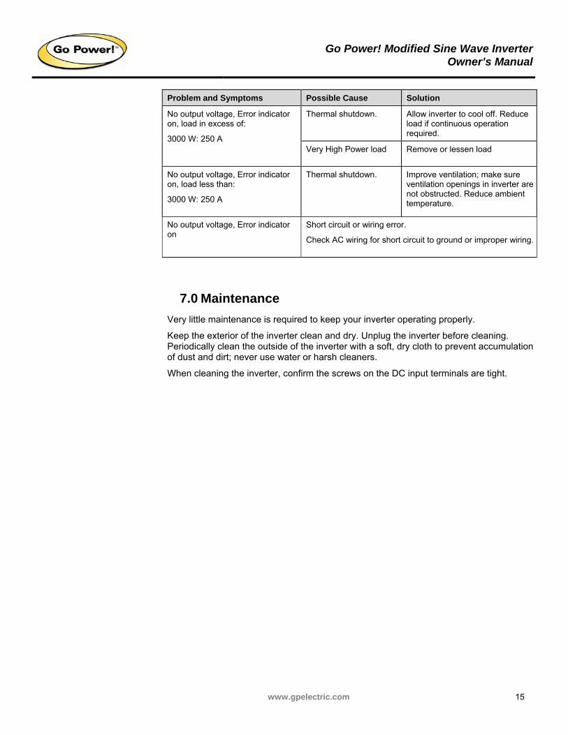
Problem and Symptoms Possible Cause Solution
Thermal shutdown. Allow inverter to cool off. Reduce load if continuous operation required.
No output voltage, Error indicator on, load in excess of:
3000 W: 250 A Very High Power load Remove or lessen load
No output voltage, Error indicator on, load less than:
3000 W: 250 A
Thermal shutdown. Improve ventilation; make sure ventilation openings in inverter are not obstructed. Reduce ambient temperature.
No output voltage, Error indicator on
Short circuit or wiring error.
Check AC wiring for short circuit to ground or improper wiring.
7.0 Maintenance
Very little maintenance is required to keep your inverter operating properly.
Keep the exterior of the inverter clean and dry. Unplug the inverter before cleaning. Periodically clean the outside of the inverter with a soft, dry cloth to prevent accumulation of dust and dirt; never use water or harsh cleaners.
When cleaning the inverter, confirm the screws on the DC input terminals are tight.
Go Power! Modified Sine Wave InverterOwner’s Manual
www.gpelectric.com 16
8.0 Warranty
8.1 Go Power! 1 Year Limited Warranty
Go Power! provides the following limited 1 year warranty (“Warranty”) coverage as applicable to the purchaser (“Purchaser”) of the Go Power! branded product (“Product”) directly from Go Power! The following constitutes the terms and conditions of that limited warranty.
8.1.1 What the Go Power! Warranty Covers and for How Long
Subject to the exclusions and claim procedure set out below, Go Power! warrants for a period of 1 year from the date of purchase at the point-of-sale to the original end-user customer (“Sale Date”), that the Go Power! Product provides coverage as follows:
For the period ending 2 years from the Sale Date, Go Power! will, at Go Power!’s discretion, repair or replace the Product which fails to meet the Product Specifications due to a defect in materials or workmanship or apply credit towards the purchase of new Go Power! Product.
To exercise this right, the Purchaser shall ship, at its own expense, and return the Product to Go Power! according to the return instructions detailed below, and Go Power! will, repair or replace the Product and return it to the Purchaser free of charge, or offer credit towards the purchase of new Product.
Go Power! shall be entitled, at its discretion, to use new and/or reconditioned parts in performing warranty repair or providing a replacement Product. Go Power! also reserves the right to use parts or Product of original or improved design in any repair or replacement. All replaced Product and/or any parts removed from repaired Products become the property of Go Power!
If Go Power! chooses to repair or replace a Product, the above warranty will continue to apply and remain in effect for the balance of the warranty period calculated from the Sale Date (and not the repair or replacement date).
If Go Power! chooses to offer a credit towards the purchase of new Product, then the warranty in effect and applicable to the new Product shall apply to the new Product.
8.1.2 What the Go Power! Warranty Does Not Cover
The Go Power! Warranty does not provide coverage for the following which are expressly excluded from the above warranty:
Failure due to normal wear and tear of the Product.
Failure caused by separate computer software supplied with or associated with a Go Power! Product.
Failure due to fire, water, neglect, improper installation, generalized corrosion, biological infestations, or input voltages that create operating conditions beyond the maximum or minimum listed in the Go Power! specifications including lightning strikes.
Products which have been altered other than by Go Power! or authorized by Go Power!
Products that have their original identification (trademark, serial number) markings defaced altered or removed.
Products utilized as a component part of a product expressly warranted by another manufacturer.
Go Power! Modified Sine Wave InverterOwner’s Manual
www.gpelectric.com 17
Operation or storage of the Product outside the specification ranges, and/or alteration or deployment of Go Power! Products other than in accordance with any published or provided user, storage or maintenance requirements.
Failure that is in any way attributable to the improper use, storage, maintenance, installation or placement of the Go Power! Product.
Failure caused by abuse, misuse, abnormal use, or use in violation of any applicable standard, code or instructions for use in installations, including, but not limited to, those contained in the National Electrical Code, the Standards for Safety of Underwriters Laboratory, Inc., Standards for the International Electrotechnical Commission, Standards for the American National Standards Institute, or the Canadian Standards Association.
Failure due to acts of God.
8.1.3 Restrictions and Limitations to the Go Power! Warranty
This Warranty is not transferable and only applies to the Purchaser.
Go Power! does not warrant the results obtained from the implementation of recommendations made by Go Power! or its authorized distributors concerning the use, design or application of Go Power! Products
The end-user who purchases the Product assumes all responsibility and liability for loss or damage resulting from the handling or use of Go Power! Products.
Go Power!'s liability on any claim, whether in warranty, contract, negligence, or any other legal theory, for loss, damage or injury arising directly or indirectly from or in relation to the use of the Go Power! Product shall in no event exceed the purchase price of the Go Power! Product which gave rise to the claim. IN NO EVENT SHALL GO POWER! BE LIABLE FOR PUNITIVE, SPECIAL, INCIDENTAL OR CONSEQUENTIAL DAMAGES WHETHER FORSEEABLE OR NOT INCLUDING BUT NOT LIMITED TO LOSS OF PROFITS OR REVENUES, LOSS OF USE OF GOODS, OR LOSS OF BARGAIN.
The Warranty set out above is the sole warranty granted by Go Power! with respect to the Product. No oral understanding, representations or warranties shall be of any effect and Go Power! makes no further warranties, express or implied concerning the Go Power! Products other than the Warranty set out above. The Buyer, where permitted by applicable law, hereby expressly waives any statutory or implied warranty that the Go Power! Product shall be merchantable or fit for a particular purpose.
8.2 Warranty Return Procedure
This warranty procedure is based on the typical flow of sale: Go Power! → Supplier → Dealer → End User
8.2.1 End Users
Contact your sales representative or Dealer and discuss the problem. Often the sales representative can troubleshoot common scenarios. If applicable, warranty will be handled between the End User and the Dealer. Go-Power! will only accept returned items from an End User as a last resort. If you are unable to contact the Dealer, or the Dealer refuses to provide service, please contact Go-Power! directly.
8.2.2 Dealers
Dealers will handle warranty either through their supplier or Go-Power! if they qualify as a Purchaser.
Go Power! Modified Sine Wave InverterOwner’s Manual
www.gpelectric.com 18
8.2.3 Units Bought Directly from Go Power!
The Purchaser will return the product, freight prepaid, to Go Power! You must obtain a Return Material Authorization (RMA) number from Go Power! before returning a product. The RMA number MUST be clearly indicated on the outside of the box.
Items received without an RMA number will be refused.
8.3 Additional Information
Unless approved by Go Power! management, all product shipped collect to Go Power! will be refused.
Test items or items that are not under warranty, or units that are not defective, will be charged a minimum bench charge of ($50.00 US) plus taxes and shipping.
A 15% restocking charge will be applied on goods returned and accepted as “new” stock.
8.4 Out of Warranty Items
Go Power! electronic products are non-repairable, Go Power! does not perform repairs on its products nor does it contract out those repairs to a third party. Go-Power! does not supply schematics or replacement parts for any of its electronic products.
Go Power! Modified Sine Wave InverterOwner’s Manual
www.gpelectric.com 19
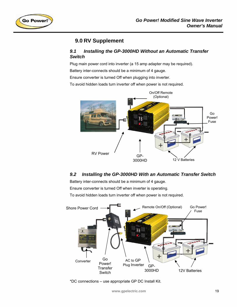
9.0 RV Supplement
9.1 Installing the GP-3000HD Without an Automatic Transfer Switch
Plug main power cord into inverter (a 15 amp adapter may be required).
Battery inter-connects should be a minimum of 4 gauge.
Ensure converter is turned Off when plugging into inverter.
To avoid hidden loads turn inverter off when power is not required.
9.2 Installing the GP-3000HD With an Automatic Transfer Switch
Battery inter-connects should be a minimum of 4 gauge.
Ensure converter is turned Off when inverter is operating.
To avoid hidden loads turn inverter off when power is not required.
*DC connections – use appropriate GP DC Install Kit.
12 V Batteries
On/Off Remote (Optional)
Shore Power Cord
Go Power!
Transfer Switch
Converter
RV Power GP-
3000HD
Go Power! Fuse
Go Power! Fuse
Remote On/Off (Optional)
AC to GP Plug Inverter
12V Batteries GP-
3000HD

www.gpelectric.com
© 2008 Carmanah Technologies Corporation www.carmanah.com
Go Power!
Building 4, 203 Harbour Road Victoria, British Columbia
Canada V9A 3S2 Toll Free: 1.877.722.8877 | Fax: +1.250.380.0062
Email: [email protected]
Number: 53534_MAN_GP_Inverter_3000_ vC