Embed Size (px)
Citation preview
GNU RADIO BEACON RECEIVER FOR IONOSPHERIC STUDY
TAI WOOI LING
This Report Is Submitted In Partial Fulfillment Of Requirements For The Bachelor
Degree of Electronic Engineering (Telecommunication Electronic)
Faculty of Electronics and Computer Engineering
Universiti Teknikal Malaysia Melaka
June 2016
ii
iii
DECLARATION
iv
v
DEDICATION
Dedicated to my beloved parents
Tai Mok Lam
and
Tor Poo Chin,
siblings
and
all supported friends
vi
ACKNOWLEDGEMENT
First of all, I would like to thank my supervisor, Dr. Ho Yih Hwa for the
guidance and advice for me to develop idea and knowledge in my final year project.
Besides that, I am very appreciating the help given by lab assistants Mr. Mohd Sufian
Bin Abu Talib, and Mr. Mohd Aeini Bin Amin. Both of them had guided me the way of
using signal analyzer and network analyzer. Furthermore, I would like to thank my
friends and family for their continuous support and motivation.
vii
ABSTRACT
GNU Radio beacon receiver is a digital beacon receiver developed to receive
beacon signals (150MHz and 400MHz) from LEO satellites for ionospheric study. This
project is implemented based on software-defined radio (SDR) technology. Open source
software GNU Radio is used with its friendly hardware USRP to perform real time
reception. Some of the components like mixer, filter and demodulator are programed by
GNU Radio, so greatly reduce the complexity of the circuit, thus, greatly reduce the cost
of fabrication and maintenance compares to analog beacon receiver. Besides that, a
satellite tracking program is developed to aim the reception of beacon signals. Satellite
tracking program is developed by writing a python script that use PyEphem library for
implementing astronomical algorithm.
viii
ABSTRAK
GNU Radio beacon penerima adalah penerima beacon digital yang dibangunkan
untuk menerima isyarat beacon (150MHz dan 400MHz) dari satelit LEO untuk kajian
ionosfera. Projek ini dilaksanakan berdasarkan teknologi radio (SDR). Perisian GNU
Radio digunakan dengan USRP untuk melaksanakan isyarat daripada satelit LEO.
Beberapa komponen seperti mixer, penapis dan penyahmodulat diprogramkan oleh
GNU Radio. Dengain ini, kerumitan litar dapat dikurangkan, Selain itu, ia juga
mengurangkan kos fabrikasi dan penyelenggaraan berbanding dengan penerima beacon
analog. Selain itu, program pengesanan satelit juga dibangunkan untuk mengesan satelit
bagi tujuan penerimaan isyarat beacon yang Berjaya. Program pengesanan satelit
dibangunkan dengan menulis skrip python yang menggunakan modul PyEphem untuk
melaksanakan algoritma astronomi.
ix
TABLE OF CONTENTS
CHAPTER TITLE PAGES
BORANG PENGESAHAN STATUS LAPORAN ii
DECLARATION iii
DEDICATION v
ACKNOWLEDGEMENT vi
ABSTRACT vii
ABSTRAK viii
TABLE OF CONTENTS ix
LIST OF FIGURES xii
LIST OF TABLES xiv
LIST OF ABBREVIATIONS xv
LIST OF SYMBOLS xvii
1 INTRODUCTION
1.1 Project Overview 1
1.2 Problem Statement 2
1.3 Objectives 3
1.4 Scope of Project 3
1.5 Thesis Outline 4
2 LITERATURE REVIEW
2.1 Software-defined Radio (SDR) 5
x
2.1.1 SDR Architecture 6
2.1.2 Universal Software Radio Peripheral (USRP) 8
2.1.3 GNU Radio 9
2.1.3.1 Universal Hardware Driver (UHD) 10
2.2 Ionosphere 10
2.2.1 Effect of Ionosphere to the Radio Signal or
Electromagnetic Wave 12
2.2.2 Total Electron Content (TEC) 13
2.3 LEO-based Sources 15
3 METHODOLOGY
3.1 Overall Operation 18
3.2 Satellite Tracking 19
3.2.1 Beacon Satellite 20
3.2.2 Advanced Interactive Python Shell: IPython 21
3.2.3 Python Script 21
3.3 GNU Radio Beacon Receiver 24
3.3.1 Quadrifilar Helix (QFH) Antenna 24
3.3.2 USRP1 and TVRX2 25
3.3.3 GNU Radio Companion 27
3.4 Flow of the Project 31
4 RESULTS AND DISCUSSIONS
4.1 Satellite Tracking 33
4.1.1 Usage 34
4.1.2 Normal Mode and Condition Mode 36
4.1.3 Update of TLE File 38
xi
4.1.4 Location and Time 39
4.1.5 Condition Mode with Different Durations 40
4.1.6 TLE File with and without Search of Particular
Satellite
41
4.1.7 Single Satellite Searching 42
4.1.8 Shortage 43
4.2 GNU Radio Beacon Receiver 43
4.2.1 Usage 44
4.2.2 Signal Reception 45
4.2.2.1 Cause: Performance of QFH Antenna 47
4.2.2.2 Cause: Cable Loss 48
4.2.2.3 Cause: Receiver Noise 49
4.2.2.4 Thermal Noise and Noise Figure 50
4.3 Summary 51
5 CONCLUSION
5.1 Conclusion 52
5.2 Future Work 53
REFERENCES 54
xii
LIST OF FIGURES
FIGURE NO TITLE PAGES
2.1 SDR Architecture 7
2.2 Standard USRP Architecture 8
2.3 Front-end Architecture 9
2.4 Layers of Ionosphere with its composition 11
3.1 Illustration of the operation of GNU Radio Beacon
Receiver
18
3.2 Location of FKEKK of UTeM 22
3.3 Flow for satellite tracking programming 23
3.4 QFH Antennas 24
3.5 Daughter board – TVRX2 26
3.6 Mother board - USRP1 26
3.7 GRC Flow Graph 27
3.8 General Properties of UHD:USRP Source 28
3.9 RF Options Properties of UHD:USRP Source 29
3.10 General Properties of Frequency Xlating FIR Filter 30
3.11 General Properties of Low-pass Filter Taps 30
3.12 General Properties of File Sink 31
3.13 Flow of the project 32
4.1 Usage of the python script of the satellite tracking 34
4.2 Result of running the program in normal mode using
default optional options
36
4.3 Result of running the program in condition mode using
default optional options
37

xiii
4.4 Result of running the program in normal mode with
updated TLE of beacon satellite
38
4.5 Result of running the program in normal mode with
location and time are given
39
4.6 Result of running the program in condition mode with
given duration
40
4.7 Result of running the program in normal mode with
given TLE file without search of single satellite
41
4.8 Result of running the program in normal mode with
given TLE file with search of single satellite
41
4.9 Result of search of single satellite in normal mode 42
4.10 Result of search of single satellite that is not included
in still-active beacon satellite in normal mode
42
4.11 Usage of the python script of the GNU Radio Beacon
Receiver
44
4.12 Frequency display for before (left) and after (right)
Frequency Xlating FIR Filter in VHF (150MHz)
channel
45
4.13 Frequency display for before (left) and after (right)
Frequency Xlating FIR Filter in UHF (400MHz)
channel
45
4.14 Return loss of the (a) 150MHz QFH antenna, (b)
400MHz QFH antenna
47
4.15 Received power at (a) 150MHz, (b) 400MHz 47
4.16 Noise floor of the receiver (a) without connection with
antenna, (b) with connection with antenna
49
4.17 Noise floor of the receiver when the channel
bandwidth is (a) 250kHz, (b) 400kHz, (c) 4MHz
50
xiv
LIST OF TABLES
TABLE NO TITLE PAGES
3-1 List of Beacon Satellite 20
3-2 List of TLE Download Webpage Link 21
xv
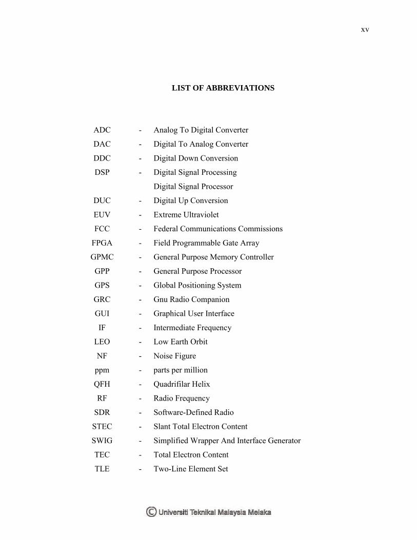
LIST OF ABBREVIATIONS
ADC - Analog To Digital Converter
DAC - Digital To Analog Converter
DDC - Digital Down Conversion
DSP - Digital Signal Processing
Digital Signal Processor
DUC - Digital Up Conversion
EUV - Extreme Ultraviolet
FCC - Federal Communications Commissions
FPGA - Field Programmable Gate Array
GPMC - General Purpose Memory Controller
GPP - General Purpose Processor
GPS - Global Positioning System
GRC - Gnu Radio Companion
GUI - Graphical User Interface
IF - Intermediate Frequency
LEO - Low Earth Orbit
NF - Noise Figure
ppm - parts per million
QFH - Quadrifilar Helix
RF - Radio Frequency
SDR - Software-Defined Radio
STEC - Slant Total Electron Content
SWIG - Simplified Wrapper And Interface Generator
TEC - Total Electron Content
TLE - Two-Line Element Set
xvi
UHF - Ultra High Frequency
URL - Uniform Resource Locator
USB - Universal Serial Bus
USRP - Universal Software Radio Peripheral
UTC - Coordinated Universal Time
VHF - Very High Frequency
VTEC - Vertical Total Electron Content
xvii
LIST OF SYMBOLS
- Plasma Frequency
- Height Of The Ionospheric Pierce Point
- Radius Of The Earth
- Voltage Peak To Peak
- Ultra High Frequency
- Very High Frequency
- Common Frequency
- Mass Of Electron
- Noise In Frequency Term
- Noise In Phase Term
- Velocity Of The Slant Path
- Permittivity In Free Space
b - Receiver Clock Biases
B - Satellite Clock Biases
Bandwidth
bps - Bit Per Second
D - True Range
dB - Decibel
e - Charge Of Electron
Electronic Time Delay Within Receiver
E - Electronic Time Delay Within Satellite
f - Transmitted Frequency
I - Ionospheric Time Delay
km - Kilo Meter
xviii
L - Level
log - Logarithm
MHz - Mega Hertz
Msps - Mega Samples Per Second
N - Electron Density
Final Noise Power Level
n - Refractive Index
Bit Per Sample
s - Path Between Transmitter And Receiver
T - Tropospheric Time Delay
- Elevation Angle
- Cable Loss in dB
- Transmitted Power
- Received Power
- Final Signal Power Level
- Received Signal Power Level
- Gain
- Boltzmann‟s Constant
- Temperature in Kelvin
- Noise Figure
- Total Noise Factor
1
CHAPTER 1
INTRODUCTION
1 Overview
This chapter presents overview of the project, problems that lead to the
development of the project, objective of the project, scope of the project and thesis
outline.
1.1 Project Overview
Ionospheric tomographic or beacon receiver used for ionospheric study is very
important in radio communication system. It estimates the electron density in the
ionosphere that brings great effect to radio propagation in the atmosphere. Total electron
content (TEC) is the parameter and is measured in unit of TECU ( ). This
parameter images the ionosphere and helps to make correction of propagation effects
due to ionosphere on the applied radio communication system [1, 2].
Radio link between satellite and ground station plays a vital role nowadays, this
link used wisely in communication, navigation and surveillance. The radio propagates
in free space encounters some changes. The phase advance and Doppler shift of a carrier,
group retardation and time delay of a modulation, Faraday rotation of the polarization
and wedge refraction of wave direction are all due to total electron content [2].
The development of software-defined radio (SDR) system has made a lot of
analog signal processing to digital signal processing by only implement software on a
general purpose computer. This allows the receiver software to be continuously
2
improved and edited to adapt to the change of requirements and technologies. An
implemented digital beacon receiver is described by Yamamoto [2008] [3]. In this study,
a digital beacon receiver known as GNU Radio Beacon Receiver is built based on the
work of Yamamoto.
Signals with different frequencies have different effects when encounter with
ionosphere. Hence, a minimum of two downlink signals receptions from satellites is
needed in order to study the ionosphere by comparing its differences. In this study,
digital beacon receiver is designed to receive beacon signals (150MHz & 400MHz) from
LEO satellites. It is developed based on a software toolkit known as GNU Radio and its
friendly hardware called Universal Software Radio Peripheral (USRP), raising its name
GNU Radio Beacon Receiver. The stored signals in binary data are saved for future
development. Before developing GNU Radio Beacon Receiver, a program is developed
to track the rise time and set time of satellites based on a high level language known as
Python (version 2.7.6) with an astronomical algorithm library known as PyEphem
(version 3.7.6.0).
1.2 Problem Statement
Previous beacon receivers are analog and this encounters a lot of problems.
Analog beacon receivers are limited to only few operational transmitting platforms.
Besides that, it is more costly due to fabrication and continuous maintenance. Moreover,
it is not portable.
However, GNU Radio Beacon Receiver requires only few components, and most
of the components are implemented by software, so greatly reduce the use of
components and thus reduce the cost for fabrication. It doesn‟t require much
maintenance as it has less components. Moreover, it can be further developed to extend
or increase its ability for ionospheric study by simply changing the programming.
Furthermore, the available TEC map provided in internet network is a worldwide
TEC image. It doesn‟t provide much about the information detail of ionosphere on a
3
specific location on the Earth. Therefore, a beacon receiver should be owned by
hobbyists and academics to extract detail information of the regional ionosphere.
The challenge in this project is to receive beacon signals from LEO satellites
which do not appear on the sky all the time. LEO satellites have short orbital sidereal
periods normally within 2 hours. The field-of-view is roughly 15 minutes on any
location on the Earth. Therefore, a program used to track the visibility of the LEO
satellites is developed.
1.3 Objectives
The main objective of this project is to develop a digital beacon receiver which
can receive 150MHz and 400MHz signals and store them into a separated file for future
development. Specifically, this project involves the following purpose:
i. To develop a low cost digital beacon receiver that is capable to receive
150MHz and 400MHz signals.
ii. To develop a program that is capable to track the visible time of the satellites.
iii. To demonstrate how the combination of USRP and GNU Radio can be used
to realize digital beacon receiver.
iv. To reduce the complexity of beacon receiver by changing it from analog to
digital.
1.4 Score of Project
This project studies only the ionosphere, one of the atmosphere‟s layers. This
project implements the early technique which utilizes the beacon signals (150MHz and
400MHz) propagated from Low Earth Orbit or LEO satellites. Many parameters can be
measured by existing beacon receivers. However, this project only receive beacon
signals, measure of total electron content (TEC) is under future work.
4
This project can be divided into two parts. First, a program which is capable to
track the visible time of satellites is developed using Python - a high level language with
a PyEphem - a library for astronomical algorithm. Second, the beacon signals are
received by the combination of the works of the USPR and the GNU Radio software.
This project includes the following works stated below:
i. Development of a program that is written using Python with an important
library, PyEphem to interpret two line element (TLE) that contain satellite‟s
information in order to track its rise time and set time for a particular earth
station.
ii. Implementation of receiver based on SDR technology by using GNU Radio
software and USRP hardware.
iii. Development of back end components using GNU Radio Companion (GRC)
in GNU Radio
1.5 Thesis Outline
In this paper, software-defined radio technology, GNU Radio software and its
friendly hardware USRP are discussed briefly in Chapter 2. Literature review on
ionosphere and its effects on radio signal that propagate to ionosphere are discussed too
in Chapter 2.
The methodology used to develop satellite tracking program and GNU Radio
Beacon Receiver are described in Chapter 3. Overall operation is discussed, followed by
the methodologies for satellite tracking program and GNU Radio Beacon Receiver.
Besides that, flow of the project is described in detail.
Results and discussions are included in Chapter 4. Details discussions on the
results are provided. Lastly, conclusion and plan of future work are made and are
presented in Chapter 5.
5
CHAPTER 2
LITERATURE REVIEW
2 Overview
This chapter presents the review of Software-defined Radio (SDR), Ionosphere
and LEO-based sources. Inside the topic of SDR, there are subtopics for Universal
Software Radio Peripheral (USRP) and GNU Radio. The effect of ionosphere on signal
and the main parameter of the ionosphere are reviewed. Furthermore, review on Leo-
based sources for ionospheric study is included.
2.1 Software-defined Radio (SDR)
The idea of Software-defined Radio (SDR) was introduced by Joseph Mitola in
1991 and was developed firstly for military purpose [4]. Nowadays, this technology is
being popular in commercial demand. SDR is a technology used in radio communication
system to implement signal processing in software platform. There are two main parts in
SDR technology: virtual module and hardware module. By having virtual module or
software platform, hardware like filter, mixer, amplifier, modulator, demodulator etc can
be implemented in the personal computer or specific embedding devices that are
operated under certain software [5]. Software is a set of instructions that direct the
computers or devices to operate. Meanwhile, by having a hardware module or RF
frontend to receive/transmit signal from/to real world and converts the signal between
analog and digital using ADC/DAC, we can reduce the complexity of an electronic
device. Hence, reduce the cost of manufacturing.
6
In compliance with Federal Communications Commissions (FCC) regulation,
certain frequencies are used by certain application. In response to the cost and this
regulation, many devices are manufactured with the ability to transmit and receive
certain frequencies only. Therefore, it is interest to have devices that can transmit and
receive a variety of frequencies. SDR allows devices to process signals in variety of
frequencies by simply changing its programming in software platform. Therefore, a lot
of applications can be performed by using a single set of devices [4].
Digital signal processing (DSP) is an interest in SDR. By running software,
programmable hardware performs the instruction and directs the digital signals to proper
path way. There are some techniques not available in analog world but digital world.
Indirectly, these techniques can solve the complex problems in analog world.
The virtual module in SDR technology is functioned based on programmable
hardware. There are three types of programmable hardware: field programmable gate
array (FPGA), embedded digital signal processor (DSP) and general purpose processor
(GPP). The platforms based on FPGA and DSP satisfy requirements of most of the
current wireless protocols. However, they are not very flexible. Contrarily, the platforms
based on GPP are very flexible. Therefore, personal computer is widely used in SDR
technology [6].
2.1.1 SDR Architecture
SDR is a technology in which some or all of the hardware are implemented in
software platform. Field programmable gate arrays (FPGA), digital signal processor or
any other specific programmable processors are the main devices used in SDR
technology. Figure 2.1 depicts the interface of hardware and software platforms [7].