Embed Size (px)
Citation preview
www.insidegnss.com J U L Y / A U G U S T 2 0 1 3 InsideGNSS 27
GNSS Solutions:
What is a maximum likelihood vector tracking receiver?
V ector tracking in GNSS receiv-ers is based on the idea that instead of tracking each satel-lite’s signal separately, all signals
are ultimately related to the position and velocity of the user antenna and thus can be tracked collectively. (See the discussion in this column in Sept/Oct 2012 issue of Inside GNSS by Drs. Lash-ley and Bevly for more information.)
More specifically, vector tracking uses the receiver’s position and velocity estimates to close the tracking loops. This approach has already attracted much attention and an extensive body of knowledge has documented vec-tor tracking’s superiority under weak signal conditions, such as under foliage and in urban canyons.
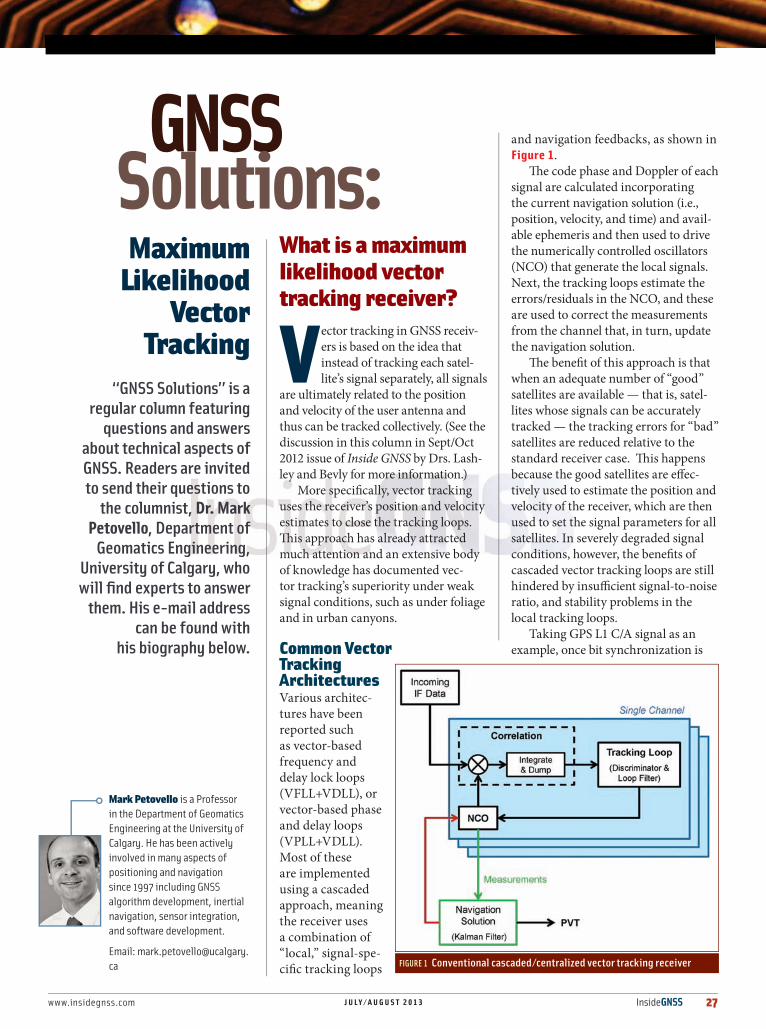
Common Vector Tracking ArchitecturesVarious architec-tures have been reported such as vector-based frequency and delay lock loops (VFLL+VDLL), or vector-based phase and delay loops (VPLL+VDLL). Most of these are implemented using a cascaded approach, meaning the receiver uses a combination of “local,” signal-spe-cific tracking loops
and navigation feedbacks, as shown in Figure 1.
The code phase and Doppler of each signal are calculated incorporating the current navigation solution (i.e., position, velocity, and time) and avail-able ephemeris and then used to drive the numerically controlled oscillators (NCO) that generate the local signals. Next, the tracking loops estimate the errors/residuals in the NCO, and these are used to correct the measurements from the channel that, in turn, update the navigation solution.
The benefit of this approach is that when an adequate number of “good” satellites are available — that is, satel-lites whose signals can be accurately tracked — the tracking errors for “bad” satellites are reduced relative to the standard receiver case. This happens because the good satellites are effec-tively used to estimate the position and velocity of the receiver, which are then used to set the signal parameters for all satellites. In severely degraded signal conditions, however, the benefits of cascaded vector tracking loops are still hindered by insufficient signal-to-noise ratio, and stability problems in the local tracking loops.
Taking GPS L1 C/A signal as an example, once bit synchronization is
Maximum Likelihood
Vector Tracking
“GNSS Solutions” is a regular column featuring
questions and answers about technical aspects of GNSS. Readers are invited to send their questions to
the columnist, Dr. Mark Petovello, Department of
Geomatics Engineering, University of Calgary, who will find experts to answer
them. His e-mail address can be found with
his biography below.
FIGURE 1 Conventional cascaded/centralized vector tracking receiver
Mark Petovello is a Professor in the Department of Geomatics Engineering at the University of Calgary. He has been actively involved in many aspects of positioning and navigation since 1997 including GNSS algorithm development, inertial navigation, sensor integration, and software development.
Email: [email protected]
28 InsideGNSS J U L Y / A U G U S T 2 0 1 3 www.insidegnss.com
GNSS SOLUTIONS
achieved, the incoming signal can be coherently integrated for 20 milliseconds without transitioning across data bit boundaries. In order to further increase the processing gain, we can apply either longer coherent integration (which may require data bit aiding) or additional non-coherent combin-ing. If local tracking loops are still being used, they need to be well-designed to balance processing gain, dynamic range, and stability of the entire tracking loop.
The other option, which circumvents the loop stability problem, is to use an open loop tracking strategy — sometimes called block processing or batch processing. This approach uses longer integration time, and measurements are generated based on the location of the strongest correlator output. The navigation solution is used to determine which correlators should be generated. In other words, there is no loop filter.
This open loop vector receiver actually has no local loop updates and can be considered as centralized vector tracking. It is very similar to the processing architecture shown in Fig-ure 1 except that it does not require the local tracking loop.
The block processing approach brings in one major ben-efit: measurements are generated based on maximum likeli-hood (ML) criterion. This means the performance of these measurements will asymptotically approach the Cramer-Rao lower bound. Aside from that, the navigation solution is exactly the same as before and still relies on traditional inputs, namely pseudorange and Doppler measurements.
Since the loop filter is replaced by the navigation solution, block processing has very little ability to identify or mitigate multipath errors. Specifically, the only option is to test the residuals or innovations in the navigation solution to try to identify outliers. In general, however, without an adequate number of good satellites, this process is usually not as effec-tive as one would like.
Although measurements generated using block processing are based on ML principles, they are still limited by the fact that only a single correlator value — the one with the largest amplitude — is used at a time from a given satellite. All the other correlator values are ignored. Consequently, although computationally efficient, information is lost in the process.
The logical question that follows is: why not use all correla-tor values as “measurements” to compute the navigation solu-tion? This is precisely the idea behind ML navigation solutions.
Vector Tracking using ML Navigation SolutionUnlike the block processing approach just described, vector tracking based on ML navigation solution estimation projects the signal power from all correlators from all satellites into the navigation (i.e., position and velocity) domain. The final navigation solution is then obtained from the point in the navigation domain that has the most power.
This ML navigation solution can provide additional pro-cessing gain across all satellites in the face of weak signals or interference. In some articles on this subject, a similar
www.NavtechGPS.com
+1-703-256-8900 • 800-628-0885
Woman-Owned Small Business
Your ONE Source for GNSS Productsand Solutions
COTS integration and technical expertise
Products from 30+ manufacturers
Advanced GNSS technical training
Visit Us Booth 3613 AUVSI 2013 Washington, DCAugust 13–15
Visit Us Booth 319 ION GNSS+ 2013 Nashville, Tennessee September 18–19
www.insidegnss.com J U L Y / A U G U S T 2 0 1 3 InsideGNSS 29
algorithm is called collective detection, which combines signal powers from multiple satellites onto a geographical search space in order to acquire weak signals, and as a by-product, the maximum likelihood position estimate is also provided.
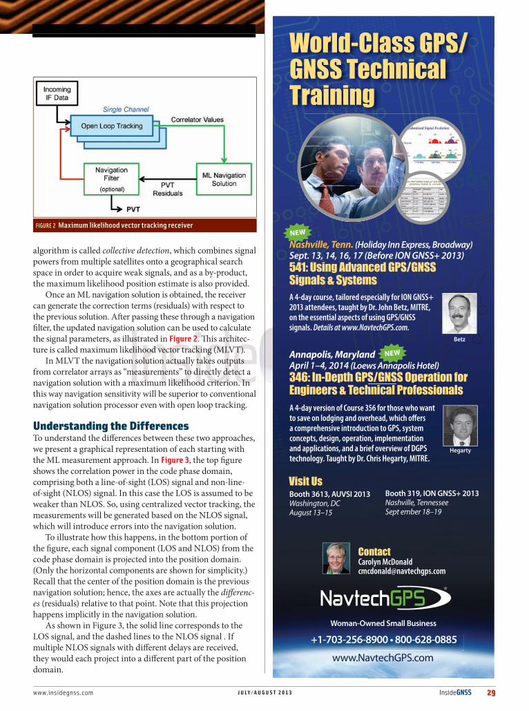
Once an ML navigation solution is obtained, the receiver can generate the correction terms (residuals) with respect to the previous solution. After passing these through a navigation filter, the updated navigation solution can be used to calculate the signal parameters, as illustrated in Figure 2. This architec-ture is called maximum likelihood vector tracking (MLVT).
In MLVT the navigation solution actually takes outputs from correlator arrays as “measurements” to directly detect a navigation solution with a maximum likelihood criterion. In this way navigation sensitivity will be superior to conventional navigation solution processor even with open loop tracking.
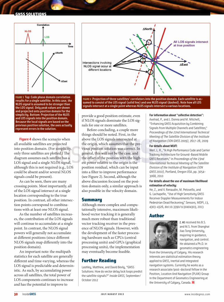
Understanding the DifferencesTo understand the differences between these two approaches, we present a graphical representation of each starting with the ML measurement approach. In Figure 3, the top figure shows the correlation power in the code phase domain, comprising both a line-of-sight (LOS) signal and non-line-of-sight (NLOS) signal. In this case the LOS is assumed to be weaker than NLOS. So, using centralized vector tracking, the measurements will be generated based on the NLOS signal, which will introduce errors into the navigation solution.
To illustrate how this happens, in the bottom portion of the figure, each signal component (LOS and NLOS) from the code phase domain is projected into the position domain. (Only the horizontal components are shown for simplicity.) Recall that the center of the position domain is the previous navigation solution; hence, the axes are actually the differenc-es (residuals) relative to that point. Note that this projection happens implicitly in the navigation solution.
As shown in Figure 3, the solid line corresponds to the LOS signal, and the dashed lines to the NLOS signal . If multiple NLOS signals with different delays are received, they would each project into a different part of the position domain.
www.NavtechGPS.com
+1-703-256-8900 • 800-628-0885
Woman-Owned Small Business
World-Class GPS/GNSS Technical Training
ContactCarolyn [email protected]
Hegarty
Betz
A 4-day course, tailored especially for ION GNSS+ 2013 attendees, taught by Dr. John Betz, MITRE, on the essential aspects of using GPS/GNSS signals. Details at www.NavtechGPS.com.
A 4-day version of Course 356 for those who want to save on lodging and overhead, which offers a comprehensive introduction to GPS, system concepts, design, operation, implementation and applications, and a brief overview of DGPS technology. Taught by Dr. Chris Hegarty, MITRE.
new
new
Visit Us Booth 3613, AUVSI 2013Washington, DCAugust 13–15
Booth 319, ION GNSS+ 2013Nashville, TennesseeSept ember 18–19
Nashville, Tenn. (Holiday Inn Express, Broadway)Sept. 13, 14, 16, 17 (Before ION GNSS+ 2013)541: Using Advanced GPS/GNSS Signals & Systems
Annapolis, MarylandApril 1–4, 2014 (Loews Annapolis Hotel)346: In-Depth GPS/GNSS Operation for Engineers & Technical Professionals
FIGURE 2 Maximum likelihood vector tracking receiver
30 InsideGNSS J U L Y / A U G U S T 2 0 1 3 www.insidegnss.com
GNSS SOLUTIONS
Figure 4 shows the scenario when all available satellites are projected into position domain. (For simplicity, only three satellites are plotted.) The diagram assumes each satellite has a LOS signal and a single NLOS signal, although this is not required (e.g., LOS could be absent and/or several NLOS signals could be present).
As can be seen, there are many crossing points. Most importantly, all of the LOS signal intersect at a single location corresponding to the true position. In contrast, all other intersec-tion points correspond to combina-tions with at least one NLOS signal.
As the number of satellites increas-es, the contribution of the LOS signals will continue to accumulate at a single point. In contrast, the NLOS signal powers will generally not accumulate at different positions (since different NLOS signals map differently into the position domain).
An important note: the multipath statistics for each satellite are generally different and time-varying, whereas the LOS signal is predictable and determin-istic. As such, by accumulating power across all satellites, the total power of LOS components continues to increase and has the potential to improve to
provide a good position estimate, even if NLOS signals dominate the LOS sig-nals for one or more satellites.
Before concluding, a couple more things should be noted. First, in the above the LOS signals intersected at the origin, which assumes that the pre-vious position solution was correct. In general, this will not be the case, and the offset of the position with the high-est power relative to the origin is the position residual, which can be input into a filter to improve performance (see Figure 2). Second, although the above discussion focused on the posi-tion domain only, a similar approach is also possible in the velocity domain.
SummaryAlthough more complex and compu-tationally intensive, maximum likeli-hood vector tracking it is generally much more robust than traditional vector tracking receiver in the pres-ence of NLOS signals. However, with the development of the faster process-ing hardware such as CPUs (central processing units) and GPUs (graphical processing units), the implementation may eventually become feasible.
Further ReadingLashley, Matthew, and David Bevly, “GNSS Solutions: How do vector delay lock loops predict the satellite signals?” Inside GNSS, September/October 2012
For information about “collective detection”:Axelrad, P., and J. Donna and M. Mitchell, “Enhancing GNSS Acquisition by Combining Signals from Multiple Channels and Satellites,” Proceedings of the 22nd International Technical Meeting of The Satellite Division of the Institute of Navigation (ION GNSS 2009), 2617-28, 2009
For details about MLVT:Weil, L. R., “A High Performance Code and Carrier Tracking Architecture for Ground-Based Mobile GNSS Receivers,” in Proceedings of the 23nd International Technical Meeting of The Satellite Division of the Institute of Navigation (ION GNSS 2010), Portland, Oregon USA, pp. 3054-3068, 2010
For details about the use of maximum likelihood estimation of velocity:He, Z., and V. Renaudin, M. Petovello, and G. Lachapelle, “Use of High Sensitivity GNSS Receiver Doppler Measurements for Indoor Pedestrian Dead Reckoning,” Sensors, MDPI, 13, 4303-4326, doi:10.3390/s130404303, 2013
AuthorZ. HE received his B.S. and M.S. from Shanghai Jiao Tong University, majoring in guidance, navigation, and control. He obtained a Ph.D. in geomatics engineering
from the University of Calgary. His research interests are statistical estimation theory applied to GNSS, inertial and integrated navigation systems. Currently he works as a research associate/post-doctoral fellow in the Position, Location And Navigation (PLAN) Group in the Department of Geomatics Engineering at the University of Calgary, Canada.
FIGURE 3 Top: Code phase domain correlation results for a single satellite. In this case, the NLOS signal is assumed to be stronger than the LOS signal. Only peak values are shown and projected onto position domain for the simplicity. Bottom: Projection of the NLOS and LOS signals into the position domain. Because the local signals are based on the previous position solution, the axes actually represent errors in the solution.
FIGURE 4 Projection of three satellites’ correlators into the position domain. Each satellite is as-sumed to consist of the LOS signal (solid line) and one NLOS signal (dashed). Note how all LOS signals intersect at a single point whereas NLOS signals intersect a various locations.
GNSS spoken here[GPS/GLONASS/BeiDou/Galileo]
One family, many solutions. Trust Trimble GNSS OEM for all your high precision applications.
© Copyright 2013, Trimble Navigation. All rights reserved. All other trademarks are the property of their respective owners. PC-039 (01/13)
www.trimble.com/gnss-inertial
L1BD910
GPS, GLONASS,BeiDou, Galileo
L1/L2BD920
GPS, GLONASS
L1/L2 L1/L2/L5BD970
GPS, GLONASS,BeiDou, Galileo
L1/L2 + HeadingBD982
GPS, GLONASS, OmniSTAR, Heading
EnclosureBX982
GPS, GLONASS, OmniSTAR, Heading
L1/L2 + CommunicationsBD920-W3G
GPS, GLONASS,WiFi, 3G
See Trimble in Booth 2801
Trimble GNSS OEM