Embed Size (px)
Citation preview

GMX 200
Installation Manual
190-00607-04 October 2008 Revision F
Page A GMX 200 Installation Manual Revision F 190-00607-04
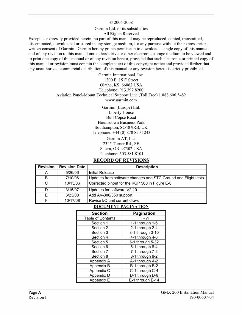
© 2006-2008
Garmin Ltd. or its subsidiaries All Rights Reserved
Except as expressly provided herein, no part of this manual may be reproduced, copied, transmitted, disseminated, downloaded or stored in any storage medium, for any purpose without the express prior written consent of Garmin. Garmin hereby grants permission to download a single copy of this manual and of any revision to this manual onto a hard drive or other electronic storage medium to be viewed and to print one copy of this manual or of any revision hereto, provided that such electronic or printed copy of this manual or revision must contain the complete text of this copyright notice and provided further that any unauthorized commercial distribution of this manual or any revision hereto is strictly prohibited.
Garmin International, Inc. 1200 E. 151st Street
Olathe, KS 66062 USA Telephone: 913.397.8200
Aviation Panel-Mount Technical Support Line (Toll Free) 1.888.606.5482 www.garmin.com
Garmin (Europe) Ltd. Liberty House
Bull Copse Road Hounsdown Business Park
Southampton, SO40 9RB, UK Telephone: +44 (0) 870 850 1243
Garmin AT, Inc. 2345 Turner Rd., SE
Salem, OR 97302 USA Telephone: 503.581.8101
URECORD OF REVISIONS
Revision Revision Date Description
A 5/26/06 Initial Release
B 7/10/06 Updates from software changes and STC Ground and Flight tests.
C 10/13/06 Corrected pinout for the KGP 560 in Figure E-8.
D 3/15/07 Updates for software V2.10.
E 6/23/08 Add AV-300/350 support.
F 10/17/08 Revise I/O unit current draw.
UDOCUMENT PAGINATION
Section Pagination Table of Contents iii - vi
Section 1 1-1 through 1-6
Section 2 2-1 through 2-4
Section 3 3-1 through 3-10
Section 4 4-1 through 4-6
Section 5 5-1 through 5-32
Section 6 6-1 through 6-4
Section 7 7-1 through 7-2
Section 8 8-1 through 8-2
Appendix A A-1 through A-2
Appendix B B-1 through B-2
Appendix C C-1 through C-4
Appendix D D-1 through D-8
Appendix E E-1 through E-14
GMX 200 Installation Manual Page i 190-00607-04 Revision F
UINFORMATION SUBJECT TO EXPORT CONTROL LAWS
This document may contain information which is subject to the Export Administration Regulations ("EAR") issued by the United States Department of Commerce (15 CFR, Chapter VII, Subchapter C) and which may not be exported, released, or disclosed to foreign nationals inside or outside of the United States without first obtaining an export license. A violation of the EAR may be subject to a penalty of up to 10 years imprisonment and a fine of up to $1,000,000 under Section 2410 of the Export Administration Act of 1979. Include this notice with any reproduced portion of this document.
WARNING
This product, its packaging, and its components contain chemicals known to the State of California to cause cancer, birth defects, or reproductive harm. This Notice is being provided in accordance with California's Proposition 65. If you have any questions or would like additional information, please refer to our web site at HUwww.garmin.com/prop65UH.
CAUTION
The GMX 200 uses a lens coated with a special anti-reflective coating that is very sensitive to skin oils, waxes and abrasive cleaners. CLEANERS CONTAINING AMMONIA WILL HARM THE ANTI-REFLECTIVE COATING. It is very important to clean the lens using a clean, lint-free cloth and an eyeglass lens cleaner that is specified as safe for anti-reflective coatings
CAUTION
All GMX 200 screen shots used in this document are current at the time of publication. Screen shots are intended to provide visual reference only. All information depicted in screen shots, including software file names, versions and part numbers, is subject to change and may not be up to date.
This manual is written for software version 2.00 or later. The software version and information in this document are subject to change without notice. Visit the Garmin web site (Uwww.garmin.com U) for current updates and supplemental information concerning the operation of this and other Garmin products.

Page ii GMX 200 Installation Manual Revision F 190-00607-04
This Page Intentionally Left Blank
GMX 200 Installation Manual Page iii 190-00607-04 Revision F
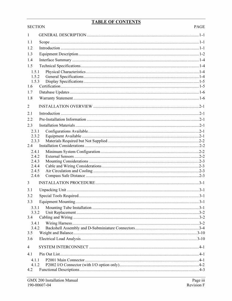
TABLE OF CONTENTS
SECTION PAGE
1 GENERAL DESCRIPTION ...........................................................................................................1-1
1.1 Scope ..............................................................................................................................................1-1
1.2 Introduction ....................................................................................................................................1-1
1.3 Equipment Description...................................................................................................................1-2
1.4 Interface Summary .........................................................................................................................1-4
1.5 Technical Specifications.................................................................................................................1-4
1.5.1 Physical Characteristics............................................................................................................1-4 1.5.2 General Specifications..............................................................................................................1-4 1.5.3 Display Specifications ..............................................................................................................1-5
1.6 Certification....................................................................................................................................1-5
1.7 Database Updates ...........................................................................................................................1-6
1.8 Warranty Statement ........................................................................................................................1-6
2 INSTALLATION OVERVIEW .....................................................................................................2-1
2.1 Introduction ....................................................................................................................................2-1
2.2 Pre-Installation Information ...........................................................................................................2-1
2.3 Installation Materials ......................................................................................................................2-1
2.3.1 Configurations Available..........................................................................................................2-1 2.3.2 Equipment Available ................................................................................................................2-1 2.3.3 Materials Required but Not Supplied .......................................................................................2-2
2.4 Installation Considerations .............................................................................................................2-2
2.4.1 Minimum System Configuration ..............................................................................................2-2 2.4.2 External Sensors .......................................................................................................................2-2 2.4.3 Mounting Considerations .........................................................................................................2-3 2.4.4 Cable and Wiring Considerations.............................................................................................2-3 2.4.5 Air Circulation and Cooling .....................................................................................................2-3 2.4.6 Compass Safe Distance ............................................................................................................2-3
3 INSTALLATION PROCEDURE...................................................................................................3-1
3.1 Unpacking Unit ..............................................................................................................................3-1
3.2 Special Tools Required...................................................................................................................3-1
3.3 Equipment Mounting......................................................................................................................3-1
3.3.1 Mounting Tube Installation ......................................................................................................3-1 3.3.2 Unit Replacement .....................................................................................................................3-2
3.4 Cabling and Wiring ........................................................................................................................3-2
3.4.1 Wiring Harness .........................................................................................................................3-2 3.4.2 Backshell Assembly and D-Subminiature Connectors.............................................................3-4
3.5 Weight and Balance......................................................................................................................3-10
3.6 Electrical Load Analysis...............................................................................................................3-10
4 SYSTEM INTERCONNECT .........................................................................................................4-1
4.1 Pin Out List.....................................................................................................................................4-1
4.1.1 P2001 Main Connector.............................................................................................................4-1 4.1.2 P2002 I/O Connector (with I/O option only)............................................................................4-2
4.2 Functional Descriptions..................................................................................................................4-3
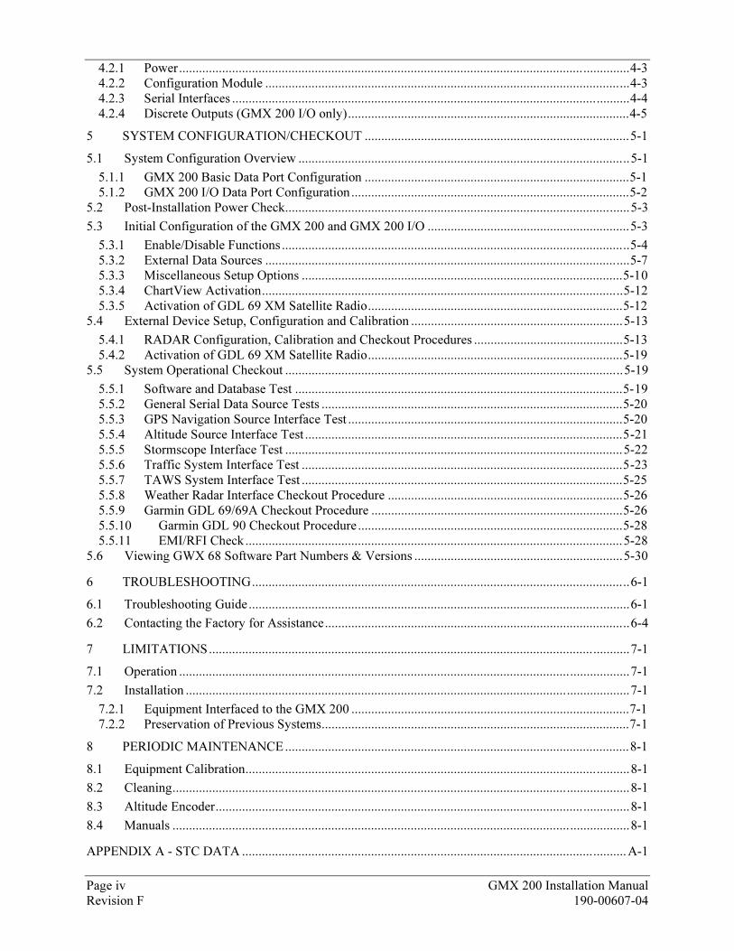
Page iv GMX 200 Installation Manual Revision F 190-00607-04
4.2.1 Power........................................................................................................................................4-3 4.2.2 Configuration Module ..............................................................................................................4-3 4.2.3 Serial Interfaces ........................................................................................................................4-4 4.2.4 Discrete Outputs (GMX 200 I/O only).....................................................................................4-5
5 SYSTEM CONFIGURATION/CHECKOUT ................................................................................5-1
5.1 System Configuration Overview ....................................................................................................5-1
5.1.1 GMX 200 Basic Data Port Configuration ................................................................................5-1 5.1.2 GMX 200 I/O Data Port Configuration....................................................................................5-2
5.2 Post-Installation Power Check........................................................................................................5-3
5.3 Initial Configuration of the GMX 200 and GMX 200 I/O .............................................................5-3
5.3.1 Enable/Disable Functions .........................................................................................................5-4 5.3.2 External Data Sources ..............................................................................................................5-7 5.3.3 Miscellaneous Setup Options .................................................................................................5-10 5.3.4 ChartView Activation.............................................................................................................5-12 5.3.5 Activation of GDL 69 XM Satellite Radio.............................................................................5-12
5.4 External Device Setup, Configuration and Calibration ................................................................5-13
5.4.1 RADAR Configuration, Calibration and Checkout Procedures .............................................5-13 5.4.2 Activation of GDL 69 XM Satellite Radio.............................................................................5-19
5.5 System Operational Checkout ......................................................................................................5-19
5.5.1 Software and Database Test ...................................................................................................5-19 5.5.2 General Serial Data Source Tests ...........................................................................................5-20 5.5.3 GPS Navigation Source Interface Test ...................................................................................5-20 5.5.4 Altitude Source Interface Test ................................................................................................5-21 5.5.5 Stormscope Interface Test ......................................................................................................5-22 5.5.6 Traffic System Interface Test .................................................................................................5-23 5.5.7 TAWS System Interface Test .................................................................................................5-25 5.5.8 Weather Radar Interface Checkout Procedure .......................................................................5-26 5.5.9 Garmin GDL 69/69A Checkout Procedure ............................................................................5-26 5.5.10 Garmin GDL 90 Checkout Procedure ................................................................................5-28 5.5.11 EMI/RFI Check..................................................................................................................5-28
5.6 Viewing GWX 68 Software Part Numbers & Versions ...............................................................5-30
6 TROUBLESHOOTING..................................................................................................................6-1
6.1 Troubleshooting Guide...................................................................................................................6-1
6.2 Contacting the Factory for Assistance............................................................................................6-4
7 LIMITATIONS...............................................................................................................................7-1
7.1 Operation ........................................................................................................................................7-1
7.2 Installation ......................................................................................................................................7-1
7.2.1 Equipment Interfaced to the GMX 200 ....................................................................................7-1 7.2.2 Preservation of Previous Systems.............................................................................................7-1
8 PERIODIC MAINTENANCE........................................................................................................8-1
8.1 Equipment Calibration....................................................................................................................8-1
8.2 Cleaning..........................................................................................................................................8-1
8.3 Altitude Encoder.............................................................................................................................8-1
8.4 Manuals ..........................................................................................................................................8-1
APPENDIX A - STC DATA ....................................................................................................................A-1
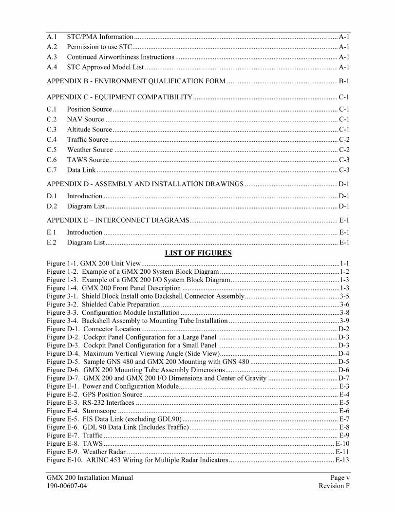
GMX 200 Installation Manual Page v 190-00607-04 Revision F
A.1 STC/PMA Information..................................................................................................................A-1
A.2 Permission to use STC...................................................................................................................A-1
A.3 Continued Airworthiness Instructions ........................................................................................... A-1
A.4 STC Approved Model List ............................................................................................................A-1
APPENDIX B - ENVIRONMENT QUALIFICATION FORM .............................................................. B-1
APPENDIX C - EQUIPMENT COMPATIBILITY................................................................................. C-1
C.1 Position Source.............................................................................................................................. C-1
C.2 NAV Source .................................................................................................................................. C-1
C.3 Altitude Source.............................................................................................................................. C-1
C.4 Traffic Source................................................................................................................................ C-2
C.5 Weather Source ............................................................................................................................. C-2
C.6 TAWS Source................................................................................................................................ C-3
C.7 Data Link ....................................................................................................................................... C-3
APPENDIX D - ASSEMBLY AND INSTALLATION DRAWINGS ....................................................D-1
D.1 Introduction ...................................................................................................................................D-1
D.2 Diagram List ..................................................................................................................................D-1
APPENDIX E – INTERCONNECT DIAGRAMS................................................................................... E-1
E.1 Introduction ................................................................................................................................... E-1
E.2 Diagram List .................................................................................................................................. E-1
LIST OF FIGURES
Figure 1-1. GMX 200 Unit View...............................................................................................................1-1 Figure 1-2. Example of a GMX 200 System Block Diagram ...................................................................1-2 Figure 1-3. Example of a GMX 200 I/O System Block Diagram.............................................................1-3 Figure 1-4. GMX 200 Front Panel Description ........................................................................................1-3 Figure 3-1. Shield Block Install onto Backshell Connector Assembly.....................................................3-5 Figure 3-2. Shielded Cable Preparation ....................................................................................................3-6 Figure 3-3. Configuration Module Installation .........................................................................................3-8 Figure 3-4. Backshell Assembly to Mounting Tube Installation ..............................................................3-9 Figure D-1. Connector Location ..............................................................................................................D-2 Figure D-2. Cockpit Panel Configuration for a Large Panel ...................................................................D-3 Figure D-3. Cockpit Panel Configuration for a Small Panel ...................................................................D-3 Figure D-4. Maximum Vertical Viewing Angle (Side View)..................................................................D-4 Figure D-5. Sample GNS 480 and GMX 200 Mounting with GNS 480 .................................................D-5 Figure D-6. GMX 200 Mounting Tube Assembly Dimensions...............................................................D-6 Figure D-7. GMX 200 and GMX 200 I/O Dimensions and Center of Gravity .......................................D-7 Figure E-1. Power and Configuration Module......................................................................................... E-3 Figure E-2. GPS Position Source............................................................................................................. E-4 Figure E-3. RS-232 Interfaces ................................................................................................................. E-5 Figure E-4. Stormscope ........................................................................................................................... E-6 Figure E-5. FIS Data Link (excluding GDL90) ....................................................................................... E-7 Figure E-6. GDL 90 Data Link (Includes Traffic) ................................................................................... E-8 Figure E-7. Traffic ................................................................................................................................... E-9 Figure E-8. TAWS................................................................................................................................. E-10 Figure E-9. Weather Radar .................................................................................................................... E-11 Figure E-10. ARINC 453 Wiring for Multiple Radar Indicators........................................................... E-13
Page vi GMX 200 Installation Manual Revision F 190-00607-04
LIST OF TABLES
Table 1-1. TSO Authorizations.................................................................................................................1-5 Table 2-1. Configurations Available.........................................................................................................2-1 Table 2-2. Accessories Provided Separately.............................................................................................2-1 Table 2-3. Options Available ....................................................................................................................2-1 Table 3-1. Socket Contact Part Numbers..................................................................................................3-2 Table 3-2. Recommended Crimp Tools ....................................................................................................3-3 Table 3-3. Backshell Assembly ................................................................................................................3-4 Table 3-4. Configuration Module Kit – 011-00979-02.............................................................................3-7 Table 3-5. Configuration Module Wire Color Reference Chart ...............................................................3-7 Table 3-6. Unit Power Loads ..................................................................................................................3-10 Table 5-1. Preferred RS-232/RS-422 Data Port Configurations (P2001).................................................5-1 Table 5-2. GMX 200 I/O Data Port Configurations (P2002)....................................................................5-2 Table 5-3. GMX 200 Series Post-Installation Checkout Log .................................................................5-31 Table 6-1. Troubleshooting Guide ............................................................................................................6-1
1 0BGeneral Description
1.1 8BScope
The information in this manual is STC approved. Only the equipment interfaces covered in this manual are within the scope of this STC. Other equipment may be suitable for use with the GMX 200, but use of such equipment is beyond the scope of this STC – additional FAA approval may be required if equipment not covered in this manual is interfaced to the GMX 200.
This document describes the GMX 200 operating with software Version 2.00 and later. All references to the GMX 200 apply to both the GMX 200 and GMX 200 I/O models, and references applicable to the GMX 200 I/O model only are identified as such.
Refer to Section X7X, Limitations, for additional information.
It is possible for installers to seek evaluation and approval of an alternate installation by means of the field approval process. This manual and all the data contained within may be used by the installer in pursuit of a field approval.
1.2 9BIntroduction
This manual describes the installation of the GMX 200 Multi-Function Display. It is intended for use by persons certified by the Federal Aviation Administration (FAA) to install avionics. It includes installation and checkout procedures for the GMX 200 to standards described in 14CFR Part 43. This installation manual applies to GMX 200 models listed in XTable 2-1X.
Figure 1-1. GMX 200 Unit View
GMX 200 Installation Manual Page 1-1 190-00607-04 Revision F
1.3 10BEquipment Description
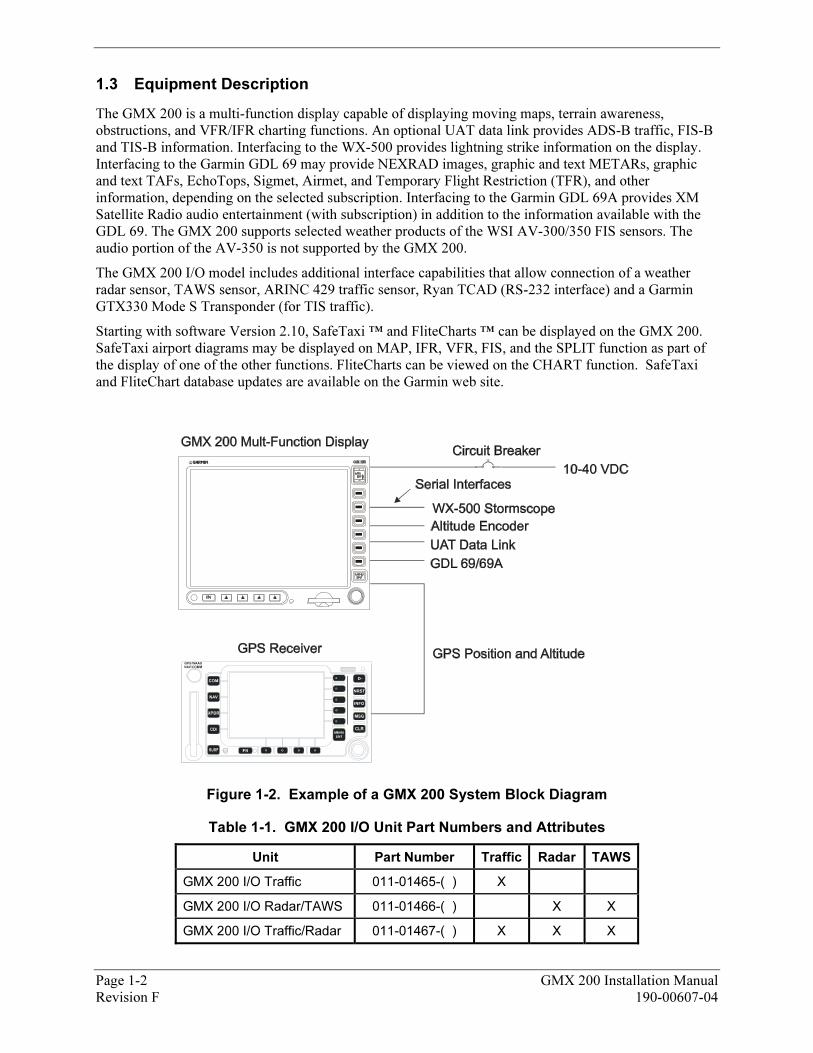
The GMX 200 is a multi-function display capable of displaying moving maps, terrain awareness, obstructions, and VFR/IFR charting functions. An optional UAT data link provides ADS-B traffic, FIS-B and TIS-B information. Interfacing to the WX-500 provides lightning strike information on the display. Interfacing to the Garmin GDL 69 may provide NEXRAD images, graphic and text METARs, graphic and text TAFs, EchoTops, Sigmet, Airmet, and Temporary Flight Restriction (TFR), and other information, depending on the selected subscription. Interfacing to the Garmin GDL 69A provides XM Satellite Radio audio entertainment (with subscription) in addition to the information available with the GDL 69. The GMX 200 supports selected weather products of the WSI AV-300/350 FIS sensors. The audio portion of the AV-350 is not supported by the GMX 200.
The GMX 200 I/O model includes additional interface capabilities that allow connection of a weather radar sensor, TAWS sensor, ARINC 429 traffic sensor, Ryan TCAD (RS-232 interface) and a Garmin GTX330 Mode S Transponder (for TIS traffic).
Starting with software Version 2.10, SafeTaxi ™ and FliteCharts ™ can be displayed on the GMX 200. SafeTaxi airport diagrams may be displayed on MAP, IFR, VFR, FIS, and the SPLIT function as part of the display of one of the other functions. FliteCharts can be viewed on the CHART function. SafeTaxi and FliteChart database updates are available on the Garmin web site.
Figure 1-2. Example of a GMX 200 System Block Diagram
Table 1-1. GMX 200 I/O Unit Part Numbers and Attributes
Unit Part Number Traffic Radar TAWS
GMX 200 I/O Traffic 011-01465-( ) X
GMX 200 I/O Radar/TAWS 011-01466-( ) X X
GMX 200 I/O Traffic/Radar 011-01467-( ) X X X
Page 1-2 GMX 200 Installation Manual Revision F 190-00607-04
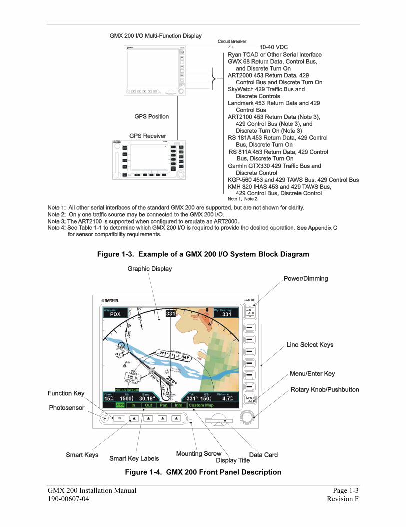
Figure 1-3. Example of a GMX 200 I/O System Block Diagram
Figure 1-4. GMX 200 Front Panel Description
GMX 200 Installation Manual Page 1-3 190-00607-04 Revision F
Page 1-4 GMX 200 Installation Manual Revision F 190-00607-04
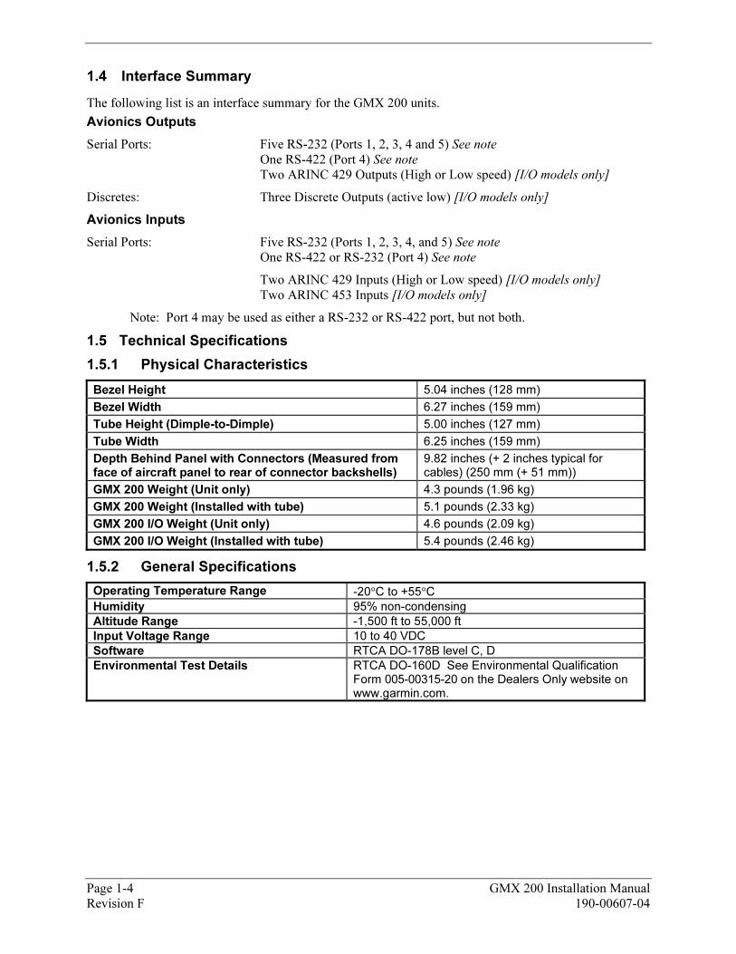
1.4 11BInterface Summary
The following list is an interface summary for the GMX 200 units.
Avionics Outputs
Serial Ports: Five RS-232 (Ports 1, 2, 3, 4 and 5) See note
One RS-422 (Port 4) See note
Two ARINC 429 Outputs (High or Low speed) [I/O models only]
Discretes: Three Discrete Outputs (active low) [I/O models only]
Avionics Inputs
Serial Ports: Five RS-232 (Ports 1, 2, 3, 4, and 5) See note
One RS-422 or RS-232 (Port 4) See note
Two ARINC 429 Inputs (High or Low speed) [I/O models only] Two ARINC 453 Inputs [I/O models only]
Note: Port 4 may be used as either a RS-232 or RS-422 port, but not both.
1.5 12BTechnical Specifications
1.5.1 43BPhysical Characteristics
Bezel Height 5.04 inches (128 mm)
Bezel Width 6.27 inches (159 mm)
Tube Height (Dimple-to-Dimple) 5.00 inches (127 mm)
Tube Width 6.25 inches (159 mm)
Depth Behind Panel with Connectors (Measured from face of aircraft panel to rear of connector backshells)
9.82 inches (+ 2 inches typical for cables) (250 mm (+ 51 mm))
GMX 200 Weight (Unit only) 4.3 pounds (1.96 kg)
GMX 200 Weight (Installed with tube) 5.1 pounds (2.33 kg)
GMX 200 I/O Weight (Unit only) 4.6 pounds (2.09 kg)
GMX 200 I/O Weight (Installed with tube) 5.4 pounds (2.46 kg)
1.5.2 44BGeneral Specifications
Operating Temperature Range -20°C to +55°C
Humidity 95% non-condensing
Altitude Range -1,500 ft to 55,000 ft
Input Voltage Range 10 to 40 VDC
Software RTCA DO-178B level C, D
Environmental Test Details RTCA DO-160D See Environmental Qualification Form 005-00315-20 on the Dealers Only website on www.garmin.com.
GMX 200 Installation Manual Page 1-5 190-00607-04 Revision F
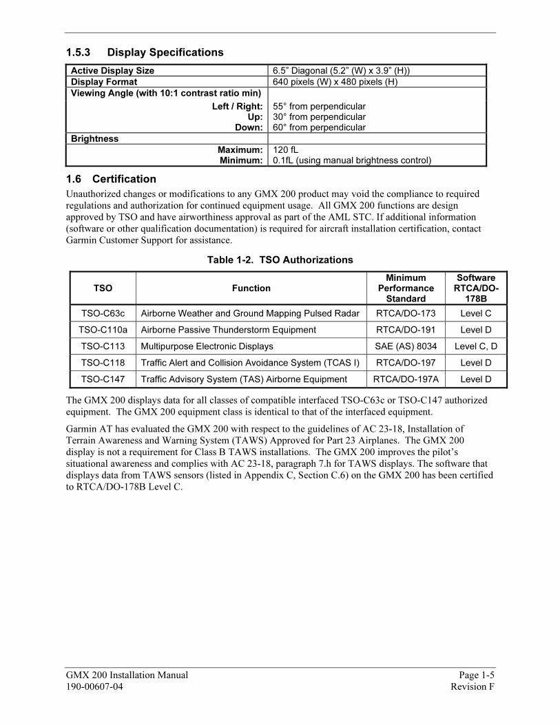
1.5.3 45BDisplay Specifications
Active Display Size 6.5” Diagonal (5.2” (W) x 3.9” (H))
Display Format 640 pixels (W) x 480 pixels (H)
Viewing Angle (with 10:1 contrast ratio min)
Left / Right:Up:
Down:
55° from perpendicular 30° from perpendicular 60° from perpendicular
Brightness
Maximum:Minimum:
120 fL 0.1fL (using manual brightness control)
1.6 13BCertification
Unauthorized changes or modifications to any GMX 200 product may void the compliance to required regulations and authorization for continued equipment usage. All GMX 200 functions are design approved by TSO and have airworthiness approval as part of the AML STC. If additional information (software or other qualification documentation) is required for aircraft installation certification, contact Garmin Customer Support for assistance.
Table 1-2. TSO Authorizations
TSO Function Minimum
Performance Standard
Software RTCA/DO-
178B
TSO-C63c Airborne Weather and Ground Mapping Pulsed Radar RTCA/DO-173 Level C
TSO-C110a Airborne Passive Thunderstorm Equipment RTCA/DO-191 Level D
TSO-C113 Multipurpose Electronic Displays SAE (AS) 8034 Level C, D
TSO-C118 Traffic Alert and Collision Avoidance System (TCAS I) RTCA/DO-197 Level D
TSO-C147 Traffic Advisory System (TAS) Airborne Equipment RTCA/DO-197A Level D
The GMX 200 displays data for all classes of compatible interfaced TSO-C63c or TSO-C147 authorized equipment. The GMX 200 equipment class is identical to that of the interfaced equipment.
Garmin AT has evaluated the GMX 200 with respect to the guidelines of AC 23-18, Installation of Terrain Awareness and Warning System (TAWS) Approved for Part 23 Airplanes. The GMX 200 display is not a requirement for Class B TAWS installations. The GMX 200 improves the pilot’s situational awareness and complies with AC 23-18, paragraph 7.h for TAWS displays. The software that displays data from TAWS sensors (listed in XAppendix CX, Section C.6) on the GMX 200 has been certified to RTCA/DO-178B Level C.
Page 1-6 GMX 200 Installation Manual Revision F 190-00607-04
1.7 14BDatabase Updates
The GMX 200 utilizes a database stored on an SD Memory datacard for easy updating and replacement. The database is updated by simply inserting an updated database card into the slot in the front panel in the GMX 200. Only Garmin approved datacards may be used in the GMX 200.
The database on the GMX 200 database card is generated from current Jeppesen-Sanderson data and converted to a format that is used by the GMX 200. The data conversion process is performed using software that is developed and maintained under Garmin AT configuration management according to RTCA/DO-200A, Standards for Processing Aeronautical Data.
GMX 200 users update their database card by purchasing database subscription updates from Jeppesen-Sanderson. The database card is programmed using a SD memory card R/W and Jeppesen-provided software. Contact Jeppesen at 800-621-5377 or www.jeppesen.com for more information and instructions. SafeTaxi and FliteChart databases may be updated once or multiple times with a subscription from the Garmin web site. When at www.garmin.com, click on In the Air, then on Aviation Databases in the quick link section and follow the instructions.
A separate SD memory card reader/writer (R/W) is required to update the database card using a PC. Contact Garmin for information on databases available for the GMX 200.
1.8 15BWarranty Statement
Limited Warranty
This Garmin product is warranted to be free from defects in materials or workmanship for two years from the date of purchase. Within this period, Garmin will at its sole option, repair or replace any components that fail in normal use. Such repairs or replacement will be made at no charge to the customer for parts or labor, provided that the customer shall be responsible for any transportation cost. This warranty does not cover failures due to abuse, misuse, accident or unauthorized alteration or repairs.
THE WARRANTIES AND REMEDIES CONTAINED HEREIN ARE EXCLUSIVE AND IN LIEU OF ALL OTHER WARRANTIES EXPRESS OR IMPLIED OR STATUTORY, INCLUDING ANY LIABILITY ARISING UNDER ANY WARRANTY OF MERCHANTABILITY OR FITNESS FOR A PARTICULAR PURPOSE, STATUTORY OR OTHERWISE. THIS WARRANTY GIVES YOU SPECIFIC LEGAL RIGHTS, WHICH MAY VARY FROM STATE TO STATE.
IN NO EVENT SHALL GARMIN BE LIABLE FOR ANY INCIDENTAL, SPECIAL, INDIRECT OR CONSEQUENTIAL DAMAGES, WHETHER RESULTING FROM THE USE, MISUSE, OR INABILITY TO USE THIS PRODUCT OR FROM DEFECTS IN THE PRODUCT. Some states do not allow the exclusion of incidental or consequential damages, so the above limitations may not apply to you.
Garmin retains the exclusive right to repair or replace the unit or software or offer a full refund of the purchase price at its sole discretion. SUCH REMEDY SHALL BE YOUR SOLE AND EXCLUSIVE REMEDY FOR ANY BREACH OF WARRANTY.
To obtain warranty service, contact your local Garmin Authorized Service Center. For assistance in locating a Service Center near you, call Garmin Customer Service at one of the numbers shown below.
Products sold through online auctions are not eligible for rebates or other special offers from Garmin. Online auction confirmations are not accepted for warranty verification. To obtain warranty service, an original or copy of the sales receipt from the original retailer is required. Garmin will not replace missing components from any package purchased through an online auction.
Garmin International, Inc. Garmin (Europe) Ltd. 1200 East 151st Street Liberty House, Bull Copse Road, Hounsdown Business Park Olathe, Kansas 66062, U.S.A. Southampton, SO40 9RB, UK Phone: 913/397.8200 Phone: +44 (0) 870 850 1243 FAX: 913/397.8282
GMX 200 Installation Manual Page 2-1 190-00607-04 Revision F
2 1BInstallation Overview
2.1 16BIntroduction
This section provides an overview of what is required for a successful GMX 200 installation. Available GMX 200 configurations are described, and installation considerations are presented.
2.2 17BPre-Installation Information
Always follow good avionics installation practices per FAA Advisory Circulars (AC) 43.13-1B and 43.13-2A, or later FAA approved revisions of these documents.
Follow the procedure in this manual as it is presented for a successful installation. Read the entire manual before beginning the procedure. The GMX 200 must be mounted in an FAA approved 6.25” wide radio stack. Perform the post installation checkout before closing the work area in case problems occur.
Complete an electrical load analysis in accordance with AC 43.13-1B, Chapter 11, on the aircraft prior to starting modification to ensure aircraft has the ability to carry the GMX 200 load. Refer to Section X3.6X for the power consumption information. Document the results of the electrical load analysis on FAA Form 337.
2.3 18BInstallation Materials
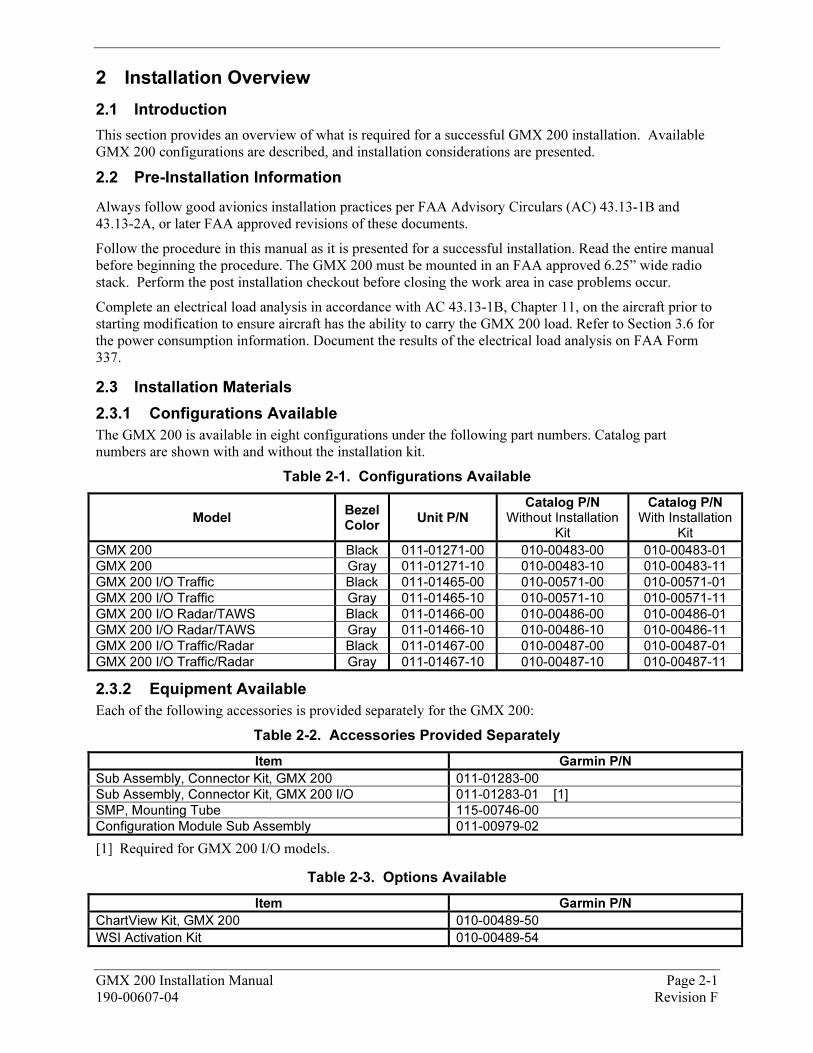
2.3.1 46BConfigurations Available
The GMX 200 is available in eight configurations under the following part numbers. Catalog part numbers are shown with and without the installation kit.
Table 2-1. Configurations Available
Model Bezel Color
Unit P/N Catalog P/N
Without Installation Kit
Catalog P/N With Installation
Kit
GMX 200 Black 011-01271-00 010-00483-00 010-00483-01
GMX 200 Gray 011-01271-10 010-00483-10 010-00483-11
GMX 200 I/O Traffic Black 011-01465-00 010-00571-00 010-00571-01
GMX 200 I/O Traffic Gray 011-01465-10 010-00571-10 010-00571-11
GMX 200 I/O Radar/TAWS Black 011-01466-00 010-00486-00 010-00486-01
GMX 200 I/O Radar/TAWS Gray 011-01466-10 010-00486-10 010-00486-11
GMX 200 I/O Traffic/Radar Black 011-01467-00 010-00487-00 010-00487-01
GMX 200 I/O Traffic/Radar Gray 011-01467-10 010-00487-10 010-00487-11
2.3.2 47BEquipment Available
Each of the following accessories is provided separately for the GMX 200:
Table 2-2. Accessories Provided Separately
Item Garmin P/N
Sub Assembly, Connector Kit, GMX 200 011-01283-00
Sub Assembly, Connector Kit, GMX 200 I/O 011-01283-01 [1]
SMP, Mounting Tube 115-00746-00
Configuration Module Sub Assembly 011-00979-02
[1] Required for GMX 200 I/O models.
Table 2-3. Options Available
Item Garmin P/N
ChartView Kit, GMX 200 010-00489-50
WSI Activation Kit 010-00489-54
Page 2-2 GMX 200 Installation Manual Revision F 190-00607-04
2.3.3 48BMaterials Required but Not Supplied
The GMX 200 equipment is intended for use with standard aviation accessories. See XAppendix C X for a list of compatible equipment. The following items are required for the installation:
• Wire (MIL-W-22759/16 or equivalent)
• Shielded Wire (MIL-C-27500 or equivalent)
• 5-Amp Circuit Breaker
• Tie wraps or lacing cord
• #8 Ring Terminals (for grounding)
• AN507 or MS24693 6-32 cadmium-plated carbon steel screws with 100° countersink flat-heads to secure the mounting tube to the aircraft structure.
• MS51957-42 or MS35206-242 stainless or cadmium-plated steel screw (PHP, 8-32x.312") for terminating shield drains to shield block.
• MS35338-137 or MS35338-42 stainless or cadmium-plated steel Split Washer (#8, .045" compressed thickness) for terminating shield drains to shield block.
• NAS1149CN832R or NAS1149FN832P stainless or cadmium-plated steel Flat Washer (#8, .032" thick, .174"ID, .375" OD) for terminating shield drains to shield block.
• Shield Terminators
• Silicon Fusion Tape
2.4 19BInstallation Considerations
2.4.1 49BMinimum System Configuration
The minimum GMX 200 installation requires the following items:
• GMX 200 or GMX 200 I/O
• External GPS Navigation sensor
NOTE
Altitude from GPS Navigation sensor or an altitude encoder is required for the internal terrain function.
2.4.2 50BExternal Sensors
External serial data sources intended for use with the GMX 200 should be checked for compatibility before installation. The list of supported devices is located in XAppendix CX of this manual.
When the GMX 200 is installed with external sensors, these sensors must be installed with manufacturer's data. Installation of any external sensors is beyond the scope of this manual and STC.
2.4.2.1 89BPosition Source
The GMX 200 uses the configured GPS source as the primary position source. If a GDL 90 is connected, the GMX 200 will use the GPS position from the GDL 90 as a backup position source (i.e. the GDL 90 position is used only when the primary GPS position is unavailable).
GMX 200 Installation Manual Page 2-3 190-00607-04 Revision F
2.4.2.2 90BAltitude Source
The GMX 200 uses altitude for its terrain awareness function and for calculating absolute altitudes for traffic. Only one type of altitude (GPS or pressure) can be configured for use by the GMX 200. An external altitude source (either GPS or pressure) is required if any of the following features is configured:
• The GMX 200 internal terrain awareness function is used (i.e. an external TAWS source is not configured)
• An Avidyne/Ryan TCAD is configured as the traffic source (altitude is only used to calculate the absolute altitude for traffic).
2.4.2.2.1 112BGPS Altitude
If the Altitude Type is set to GPS, the GMX 200 uses GPS Altitude for all of its calculations (if pressure altitude is also available to the GMX 200, pressure altitude will not be used). If a GDL 90 is connected, the GMX 200 will use the GPS Altitude from the GDL 90 as a second altitude source, and the altitude source with the highest integrity will be used for all calculations.
2.4.2.2.2 113BPressure Altitude
If the Altitude Type is set to Pressure, the GMX 200 uses Pressure Altitude for all of its calculations (if GPS Altitude is also available to the GMX 200, GPS altitude will not be used).
2.4.3 51BMounting Considerations
The GMX 200 is designed to mount in the avionics stack in the aircraft instrument panel within view and reach of the pilot. The GMX 200 must be located where the operator will have easy access to the controls and adequate viewing of the display meeting the installation limitations in section X7.2X. The preferred location would minimize pilot head movement when transitioning between looking outside of the flight deck and viewing and operating the GMX 200. Reference XFigure D-4 X. A sample diagram of a typical cockpit front panel view of the GMX 200 is shown in XFigure D-2.X The GMX 200 should be placed as high as possible in the radio stack to minimize the shifting of colors on the display. The audio panel should be the only equipment above the GMX 200.
The standard package includes a mounting tube for ease of mounting, connections, and service of the unit. Allow an additional 2” clearance to the rear of the mounting tube for routing cables. Mounting tube details are shown in XFigure D-5 X and XFigure D-6 X.
2.4.4 52BCable and Wiring Considerations
Wiring should be installed in accordance with AC 43.13-1B Chapter 11. When wire separation cannot be achieved, the following issues should be addressed:
• The cable harness should not be located near flight control cables and control, high electrical capacity lines or fuel lines
• The cable harness should be located in a protected area of the aircraft
• Do not route cable near high-energy sources
2.4.5 53BAir Circulation and Cooling
The GMX 200 does not required external cooling, but mounting configuration should not restrict intake airflow into the duct above the I/O D-sub connector or exhaust airflow out of the exhaust fans. Reference XFigure D-6 X for exhaust fan and air duct locations.
2.4.6 54BCompass Safe Distance
After reconfiguring the avionics in the cockpit panel, if the GMX 200 is mounted less than six inches from the compass, recalibrate the compass and make the necessary changes for noting correction data.

Page 2-4 GMX 200 Installation Manual Revision F 190-00607-04
This Page Intentionally Left Blank
GMX 200 Installation Manual Page 3-1 190-00607-04 Revision F
3 2BInstallation Procedure
3.1 20BUnpacking Unit
Carefully unpack the equipment and make a visual inspection of the unit for evidence of damage incurred during shipment. If the unit is damaged, notify the carrier and file a claim. To justify a claim, save the original shipping container and all packing materials. Do not return the unit to Garmin until the carrier has authorized the claim.
Retain the original shipping containers for return shipments. If the original containers are not available, a separate cardboard container should be prepared that is large enough to accommodate sufficient packing material to prevent movement.
3.2 21BSpecial Tools Required
Crimp Tool A crimp tool meeting MIL specification M22520/2-01 and a positioner/locator are required to ensure consistent, reliable crimp contact connections for the rear D-sub connectors. Refer to XTable 3-2 X for a list of recommended crimp tools.
3.3 22BEquipment Mounting
3.3.1 55BMounting Tube Installation
Use the dimensions shown in XFigure D-6 X to prepare the mounting holes for the GMX 200. You may also use the GMX 200 mounting tube itself as a template for drilling the mounting holes. Care must be taken when installing the mounting tube to ensure you can properly insert and secure the unit.
Secure the mounting tube to the avionics stack using the sixteen flat head screws specified in Section X2.3.3X. The mating holes in the avionics stack must also be countersunk to accept the screw head so that the screw head is flush with the inside surface of the mounting tube or adjoining radios.
CAUTION
Failure to properly countersink the mounting holes will result in damage to the GMX 200. Mounting screw heads must not protrude into the mounting tube.
Ensure the mounting tube is flush to the instrument panel and allow sufficient clearance for the back of the bezel of the GMX 200 to mount flush to the mounting tube. Sufficient clearance must exist in the instrument panel opening to allow ease of insertion and removal of the GMX 200.
CAUTION
If the back of the GMX 200 bezel does not mount flush to the mounting tube, connectors may not engage fully.
Cable assemblies may be attached to the mounting tube before or after the mounting tube is installed in the avionics stack. Be sure to use the specified flat head screws so the unit will slide in and out freely. Attach the front of the mounting tube to the stack. Use support brackets to attach the rear of the tube to the aircraft.
Slide the unit into the tube and hand-tighten the threaded screw shaft using a 3/32" hex. The unit will be pulled into the tube by the shaft, and the connectors will fully engage. The back of the bezel must be flush to the mounting tube.
To remove the unit from the mounting tube, unscrew the screw shaft. The unit will be loosened and then may be pulled from the tube. No special extraction tools are required.
Page 3-2 GMX 200 Installation Manual Revision F 190-00607-04
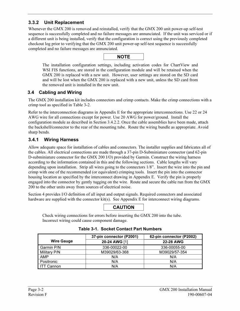
3.3.2 56BUnit Replacement
Whenever the GMX 200 is removed and reinstalled, verify that the GMX 200 unit power-up self-test sequence is successfully completed and no failure messages are annunciated. If the unit was serviced or if a different unit is being installed, verify that the configuration is correct using the previously completed checkout log prior to verifying that the GMX 200 unit power-up self-test sequence is successfully completed and no failure messages are annunciated.
NOTE
The installation configuration settings, including activation codes for ChartView and WSI FIS functions, are stored in the configuration module and will be retained when the GMX 200 is replaced with a new unit. However, user settings are stored on the SD card and will be lost when the GMX 200 is replaced with a new unit, unless the SD card from the removed unit is installed in the new unit.
3.4 23BCabling and Wiring
The GMX 200 installation kit includes connectors and crimp contacts. Make the crimp connections with a crimp tool as specified in XTable 3-2X.
Refer to the interconnection diagrams in XAppendix EX for the appropriate interconnections. Use 22 or 24 AWG wire for all connections except for power. Use 20 AWG for power/ground. Install the configuration module as described in Section X3.4.2.2X. Once the cable assemblies have been made, attach the backshell/connector to the rear of the mounting tube. Route the wiring bundle as appropriate. Avoid sharp bends.
3.4.1 57BWiring Harness
Allow adequate space for installation of cables and connectors. The installer supplies and fabricates all of the cables. All electrical connections are made through a 37-pin D-Subminiature connector (and 62-pin D-subminiature connector for the GMX 200 I/O) provided by Garmin. Construct the wiring harness according to the information contained in this and the following sections. Cable lengths will vary depending upon installation. Strip all wires going to the connectors 1/8”. Insert the wire into the pin and crimp with one of the recommended (or equivalent) crimping tools. Insert the pin into the connector housing location as specified by the interconnect drawing in XAppendix EX. Verify the pin is properly engaged into the connector by gently tugging on the wire. Route and secure the cable run from the GMX 200 to the other units away from sources of electrical noise.
Section X4X provides I/O definition of all input and output signals. Required connectors and associated hardware are supplied with the connector kit(s). See XAppendix EX for interconnect wiring diagrams.
CAUTION
Check wiring connections for errors before inserting the GMX 200 into the tube. Incorrect wiring could cause component damage.
Table 3-1. Socket Contact Part Numbers
37-pin connector (P2001) 62-pin connector (P2002) Wire Gauge 20-24 AWG [1] 22-28 AWG
Garmin P/N 336-00022-00 336-00055-00
Military P/N M39029/63-368 M39029/57-354
AMP N/A N/A
Positronic N/A N/A
ITT Cannon N/A N/A
GMX 200 Installation Manual Page 3-3 190-00607-04 Revision F
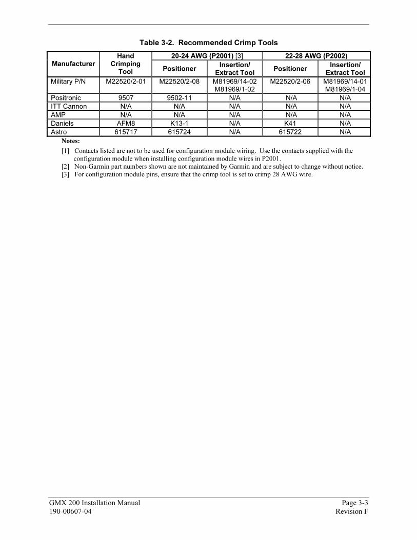
Table 3-2. Recommended Crimp Tools
20-24 AWG (P2001) [3] 22-28 AWG (P2002) Manufacturer
Hand Crimping
Tool Positioner Insertion/
Extract Tool Positioner
Insertion/ Extract Tool
Military P/N M22520/2-01 M22520/2-08 M81969/14-02
M81969/1-02
M22520/2-06 M81969/14-01M81969/1-04
Positronic 9507 9502-11 N/A N/A N/A
ITT Cannon N/A N/A N/A N/A N/A
AMP N/A N/A N/A N/A N/A
Daniels AFM8 K13-1 N/A K41 N/A
Astro 615717 615724 N/A 615722 N/A
Notes:
[1] Contacts listed are not to be used for configuration module wiring. Use the contacts supplied with the
configuration module when installing configuration module wires in P2001. [2] Non-Garmin part numbers shown are not maintained by Garmin and are subject to change without notice. [3] For configuration module pins, ensure that the crimp tool is set to crimp 28 AWG wire.
Page 3-4 GMX 200 Installation Manual Revision F 190-00607-04
3.4.2 58BBackshell Assembly and D-Subminiature Connectors
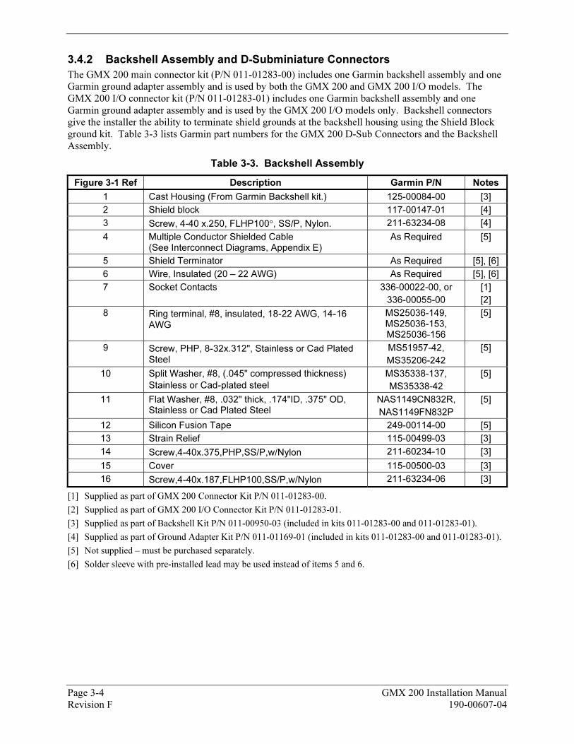
The GMX 200 main connector kit (P/N 011-01283-00) includes one Garmin backshell assembly and one Garmin ground adapter assembly and is used by both the GMX 200 and GMX 200 I/O models. The GMX 200 I/O connector kit (P/N 011-01283-01) includes one Garmin backshell assembly and one Garmin ground adapter assembly and is used by the GMX 200 I/O models only. Backshell connectors give the installer the ability to terminate shield grounds at the backshell housing using the Shield Block ground kit. XTable 3-3X lists Garmin part numbers for the GMX 200 D-Sub Connectors and the Backshell Assembly.
Table 3-3. Backshell Assembly
XFigure 3-1X Ref Description Garmin P/N Notes
1 Cast Housing (From Garmin Backshell kit.) 125-00084-00 [3]
2 Shield block 117-00147-01 [4]
3 Screw, 4-40 x.250, FLHP100°, SS/P, Nylon. 211-63234-08 [4]
4 Multiple Conductor Shielded Cable (See Interconnect Diagrams, XAppendix EX)
As Required [5]
5 Shield Terminator As Required [5], [6]
6 Wire, Insulated (20 – 22 AWG) As Required [5], [6]
7 Socket Contacts 336-00022-00, or
336-00055-00
[1]
[2]
8 Ring terminal, #8, insulated, 18-22 AWG, 14-16
AWG
MS25036-149, MS25036-153, MS25036-156
[5]
9 Screw, PHP, 8-32x.312", Stainless or Cad Plated Steel
MS51957-42,
MS35206-242
[5]
10 Split Washer, #8, (.045" compressed thickness)
Stainless or Cad-plated steel
MS35338-137,
MS35338-42
[5]
11 Flat Washer, #8, .032" thick, .174"ID, .375" OD, Stainless or Cad Plated Steel
NAS1149CN832R,
NAS1149FN832P
[5]
12 Silicon Fusion Tape 249-00114-00 [5]
13 Strain Relief 115-00499-03 [3]
14 Screw,4-40x.375,PHP,SS/P,w/Nylon 211-60234-10 [3]
15 Cover 115-00500-03 [3]
16 Screw,4-40x.187,FLHP100,SS/P,w/Nylon 211-63234-06 [3]
[1] Supplied as part of GMX 200 Connector Kit P/N 011-01283-00.
[2] Supplied as part of GMX 200 I/O Connector Kit P/N 011-01283-01.
[3] Supplied as part of Backshell Kit P/N 011-00950-03 (included in kits 011-01283-00 and 011-01283-01).
[4] Supplied as part of Ground Adapter Kit P/N 011-01169-01 (included in kits 011-01283-00 and 011-01283-01).
[5] Not supplied – must be purchased separately.
[6] Solder sleeve with pre-installed lead may be used instead of items 5 and 6.

3.4.2.1 91BShield Block Assembly Procedure
The parts for the connector and backshell assembly for GMX 200 installations are listed in XTable 3-3X and shown in XFigure 3-1X.
Figure 3-1. Shield Block Install onto Backshell Connector Assembly
GMX 200 Installation Manual Page 3-5 190-00607-04 Revision F
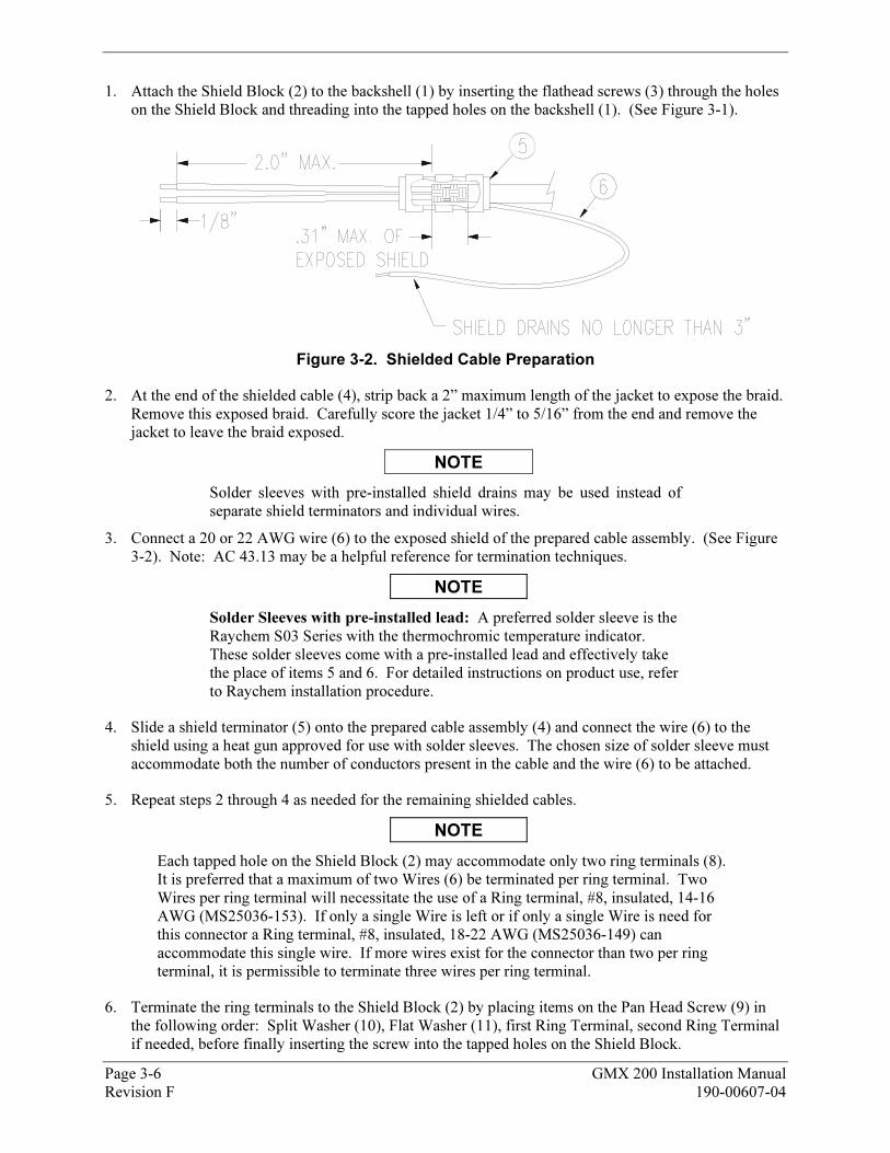
1. Attach the Shield Block (2) to the backshell (1) by inserting the flathead screws (3) through the holes on the Shield Block and threading into the tapped holes on the backshell (1). (See XFigure 3-1X).
Figure 3-2. Shielded Cable Preparation
2. At the end of the shielded cable (4), strip back a 2” maximum length of the jacket to expose the braid. Remove this exposed braid. Carefully score the jacket 1/4” to 5/16” from the end and remove the jacket to leave the braid exposed.
NOTE
Solder sleeves with pre-installed shield drains may be used instead of separate shield terminators and individual wires.
3. Connect a 20 or 22 AWG wire (6) to the exposed shield of the prepared cable assembly. (See XFigure 3-2X). Note: AC 43.13 may be a helpful reference for termination techniques.
NOTE
Solder Sleeves with pre-installed lead: A preferred solder sleeve is the Raychem S03 Series with the thermochromic temperature indicator. These solder sleeves come with a pre-installed lead and effectively take the place of items 5 and 6. For detailed instructions on product use, refer to Raychem installation procedure.
4. Slide a shield terminator (5) onto the prepared cable assembly (4) and connect the wire (6) to the shield using a heat gun approved for use with solder sleeves. The chosen size of solder sleeve must accommodate both the number of conductors present in the cable and the wire (6) to be attached.
5. Repeat steps 2 through 4 as needed for the remaining shielded cables.
NOTE
Each tapped hole on the Shield Block (2) may accommodate only two ring terminals (8). It is preferred that a maximum of two Wires (6) be terminated per ring terminal. Two Wires per ring terminal will necessitate the use of a Ring terminal, #8, insulated, 14-16 AWG (MS25036-153). If only a single Wire is left or if only a single Wire is need for this connector a Ring terminal, #8, insulated, 18-22 AWG (MS25036-149) can accommodate this single wire. If more wires exist for the connector than two per ring terminal, it is permissible to terminate three wires per ring terminal.
6. Terminate the ring terminals to the Shield Block (2) by placing items on the Pan Head Screw (9) in the following order: Split Washer (10), Flat Washer (11), first Ring Terminal, second Ring Terminal if needed, before finally inserting the screw into the tapped holes on the Shield Block.
Page 3-6 GMX 200 Installation Manual Revision F 190-00607-04
GMX 200 Installation Manual Page 3-7 190-00607-04 Revision F
7. Wrap the cable bundle with Silicone Fusion Tape (12) (GPN: 249-00114-00 or a similar version) at the point where the backshell strain relief and cast housing will contact the cable bundle.
8. Place the smooth side of the backshell strain relief (13) across the cable bundle and secure using the three screws (14). Warning: Placing the grooved side of the strain relief across the cable bundle may damage wires.
9. Attach the cover (15) to the backshell (1) using two screws (16).
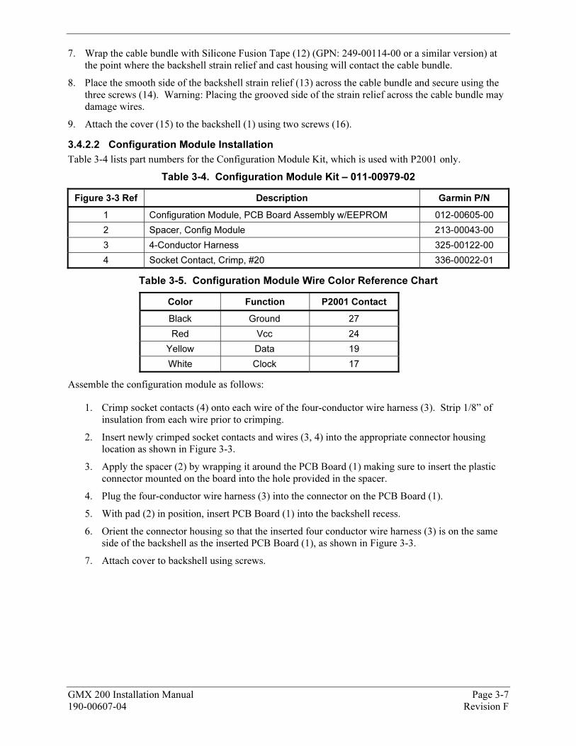
3.4.2.2 92BConfiguration Module Installation
XTable 3-4X lists part numbers for the Configuration Module Kit, which is used with P2001 only.
Table 3-4. Configuration Module Kit – 011-00979-02
XFigure 3-3X Ref Description Garmin P/N
1 Configuration Module, PCB Board Assembly w/EEPROM 012-00605-00
2 Spacer, Config Module 213-00043-00
3 4-Conductor Harness 325-00122-00
4 Socket Contact, Crimp, #20 336-00022-01
Table 3-5. Configuration Module Wire Color Reference Chart
Color Function P2001 Contact
Black Ground 27
Red Vcc 24
Yellow Data 19
White Clock 17
Assemble the configuration module as follows:
1. Crimp socket contacts (4) onto each wire of the four-conductor wire harness (3). Strip 1/8” of insulation from each wire prior to crimping.
2. Insert newly crimped socket contacts and wires (3, 4) into the appropriate connector housing location as shown in XFigure 3-3X.
3. Apply the spacer (2) by wrapping it around the PCB Board (1) making sure to insert the plastic connector mounted on the board into the hole provided in the spacer.
4. Plug the four-conductor wire harness (3) into the connector on the PCB Board (1).
5. With pad (2) in position, insert PCB Board (1) into the backshell recess.
6. Orient the connector housing so that the inserted four conductor wire harness (3) is on the same side of the backshell as the inserted PCB Board (1), as shown in XFigure 3-3X.
7. Attach cover to backshell using screws.
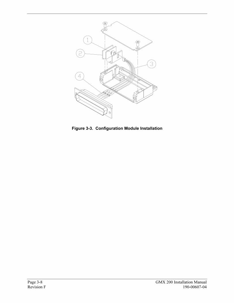
Figure 3-3. Configuration Module Installation
Page 3-8 GMX 200 Installation Manual Revision F 190-00607-04
1
23
45
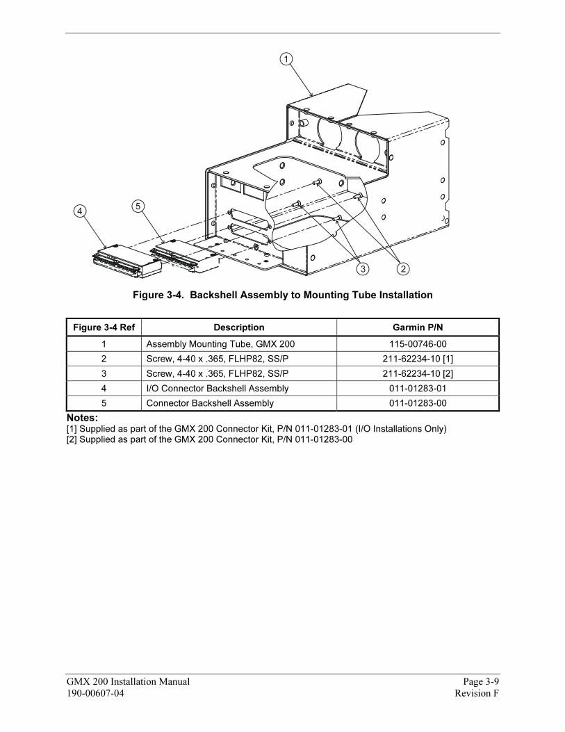
Figure 3-4. Backshell Assembly to Mounting Tube Installation
XFigure 3-4X Ref Description Garmin P/N
1 Assembly Mounting Tube, GMX 200 115-00746-00
2 Screw, 4-40 x .365, FLHP82, SS/P 211-62234-10 [1]
3 Screw, 4-40 x .365, FLHP82, SS/P 211-62234-10 [2]
4 I/O Connector Backshell Assembly 011-01283-01
5 Connector Backshell Assembly 011-01283-00
Notes: [1] Supplied as part of the GMX 200 Connector Kit, P/N 011-01283-01 (I/O Installations Only) [2] Supplied as part of the GMX 200 Connector Kit, P/N 011-01283-00
GMX 200 Installation Manual Page 3-9 190-00607-04 Revision F
Page 3-10 GMX 200 Installation Manual Revision F 190-00607-04
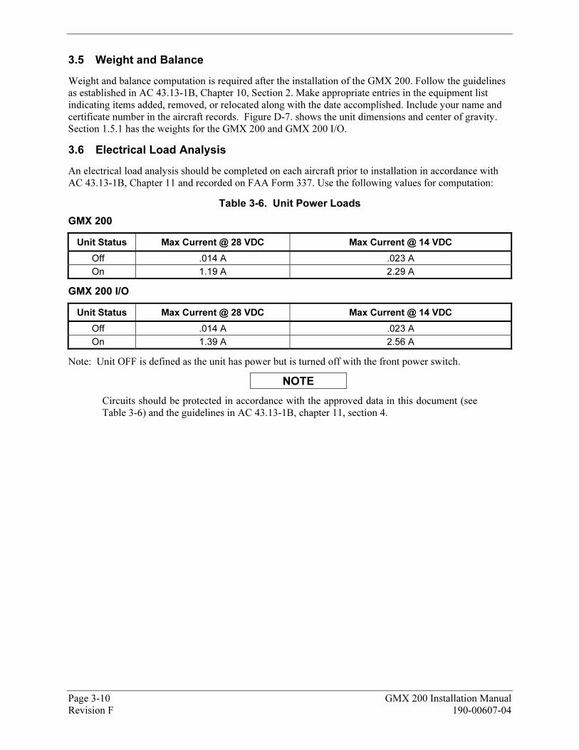
3.5 24BWeight and Balance
Weight and balance computation is required after the installation of the GMX 200. Follow the guidelines as established in AC 43.13-1B, Chapter 10, Section 2. Make appropriate entries in the equipment list indicating items added, removed, or relocated along with the date accomplished. Include your name and certificate number in the aircraft records. XFigure D-7. X shows the unit dimensions and center of gravity. Section X1.5.1X has the weights for the GMX 200 and GMX 200 I/O.
3.6 25BElectrical Load Analysis
An electrical load analysis should be completed on each aircraft prior to installation in accordance with AC 43.13-1B, Chapter 11 and recorded on FAA Form 337. Use the following values for computation:
Table 3-6. Unit Power Loads
GMX 200
Unit Status Max Current @ 28 VDC Max Current @ 14 VDC
Off .014 A .023 A
On 1.19 A 2.29 A
GMX 200 I/O
Unit Status Max Current @ 28 VDC Max Current @ 14 VDC
Off .014 A .023 A
On 1.39 A 2.56 A
Note: Unit OFF is defined as the unit has power but is turned off with the front power switch.
NOTE
Circuits should be protected in accordance with the approved data in this document (see XTable 3-6X) and the guidelines in AC 43.13-1B, chapter 11, section 4.
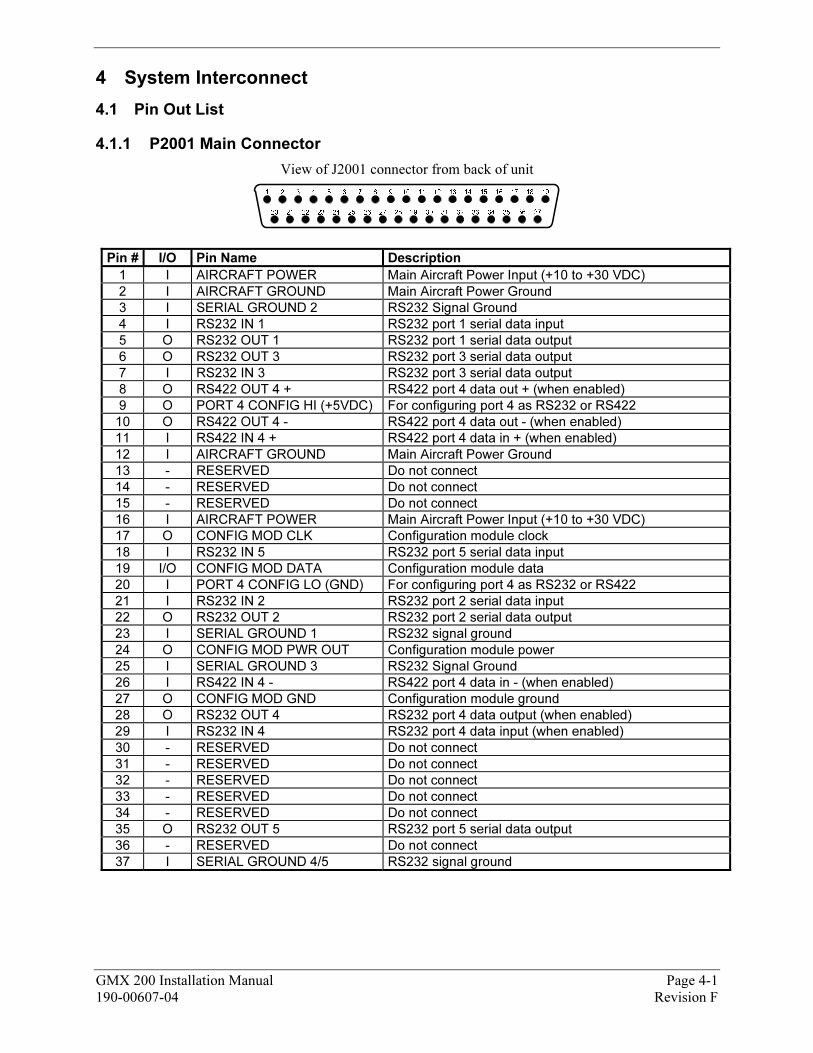
4 3BSystem Interconnect
4.1 26BPin Out List
4.1.1 59BP2001 Main Connector
View of J2001 connector from back of unit
Pin # I/O Pin Name Description
1 I AIRCRAFT POWER Main Aircraft Power Input (+10 to +30 VDC)
2 I AIRCRAFT GROUND Main Aircraft Power Ground
3 I SERIAL GROUND 2 RS232 Signal Ground
4 I RS232 IN 1 RS232 port 1 serial data input
5 O RS232 OUT 1 RS232 port 1 serial data output
6 O RS232 OUT 3 RS232 port 3 serial data output
7 I RS232 IN 3 RS232 port 3 serial data output
8 O RS422 OUT 4 + RS422 port 4 data out + (when enabled)
9 O PORT 4 CONFIG HI (+5VDC) For configuring port 4 as RS232 or RS422
10 O RS422 OUT 4 - RS422 port 4 data out - (when enabled)
11 I RS422 IN 4 + RS422 port 4 data in + (when enabled)
12 I AIRCRAFT GROUND Main Aircraft Power Ground
13 - RESERVED Do not connect
14 - RESERVED Do not connect
15 - RESERVED Do not connect
16 I AIRCRAFT POWER Main Aircraft Power Input (+10 to +30 VDC)
17 O CONFIG MOD CLK Configuration module clock
18 I RS232 IN 5 RS232 port 5 serial data input
19 I/O CONFIG MOD DATA Configuration module data
20 I PORT 4 CONFIG LO (GND) For configuring port 4 as RS232 or RS422
21 I RS232 IN 2 RS232 port 2 serial data input
22 O RS232 OUT 2 RS232 port 2 serial data output
23 I SERIAL GROUND 1 RS232 signal ground
24 O CONFIG MOD PWR OUT Configuration module power
25 I SERIAL GROUND 3 RS232 Signal Ground
26 I RS422 IN 4 - RS422 port 4 data in - (when enabled)
27 O CONFIG MOD GND Configuration module ground
28 O RS232 OUT 4 RS232 port 4 data output (when enabled)
29 I RS232 IN 4 RS232 port 4 data input (when enabled)
30 - RESERVED Do not connect
31 - RESERVED Do not connect
32 - RESERVED Do not connect
33 - RESERVED Do not connect
34 - RESERVED Do not connect
35 O RS232 OUT 5 RS232 port 5 serial data output
36 - RESERVED Do not connect
37 I SERIAL GROUND 4/5 RS232 signal ground
GMX 200 Installation Manual Page 4-1 190-00607-04 Revision F
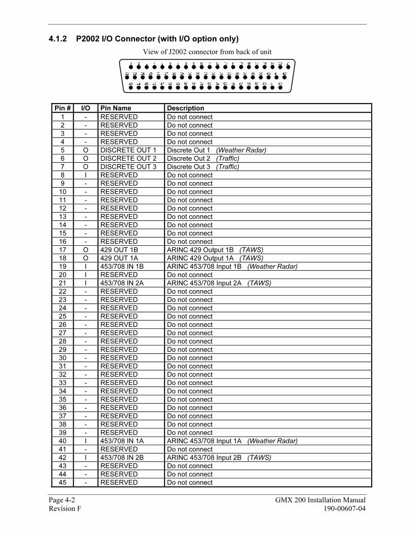
4.1.2 60BP2002 I/O Connector (with I/O option only)
View of J2002 connector from back of unit
Pin # I/O Pin Name Description
1 - RESERVED Do not connect
2 - RESERVED Do not connect
3 - RESERVED Do not connect
4 - RESERVED Do not connect
5 O DISCRETE OUT 1 Discrete Out 1 (Weather Radar)
6 O DISCRETE OUT 2 Discrete Out 2 (Traffic)
7 O DISCRETE OUT 3 Discrete Out 3 (Traffic)
8 I RESERVED Do not connect
9 - RESERVED Do not connect
10 - RESERVED Do not connect
11 - RESERVED Do not connect
12 - RESERVED Do not connect
13 - RESERVED Do not connect
14 - RESERVED Do not connect
15 - RESERVED Do not connect
16 - RESERVED Do not connect
17 O 429 OUT 1B ARINC 429 Output 1B (TAWS)
18 O 429 OUT 1A ARINC 429 Output 1A (TAWS)
19 I 453/708 IN 1B ARINC 453/708 Input 1B (Weather Radar)
20 I RESERVED Do not connect
21 I 453/708 IN 2A ARINC 453/708 Input 2A (TAWS)
22 - RESERVED Do not connect
23 - RESERVED Do not connect
24 - RESERVED Do not connect
25 - RESERVED Do not connect
26 - RESERVED Do not connect
27 - RESERVED Do not connect
28 - RESERVED Do not connect
29 - RESERVED Do not connect
30 - RESERVED Do not connect
31 - RESERVED Do not connect
32 - RESERVED Do not connect
33 - RESERVED Do not connect
34 - RESERVED Do not connect
35 - RESERVED Do not connect
36 - RESERVED Do not connect
37 - RESERVED Do not connect
38 - RESERVED Do not connect
39 - RESERVED Do not connect
40 I 453/708 IN 1A ARINC 453/708 Input 1A (Weather Radar)
41 - RESERVED Do not connect
42 I 453/708 IN 2B ARINC 453/708 Input 2B (TAWS)
43 - RESERVED Do not connect
44 - RESERVED Do not connect
45 - RESERVED Do not connect
Page 4-2 GMX 200 Installation Manual Revision F 190-00607-04
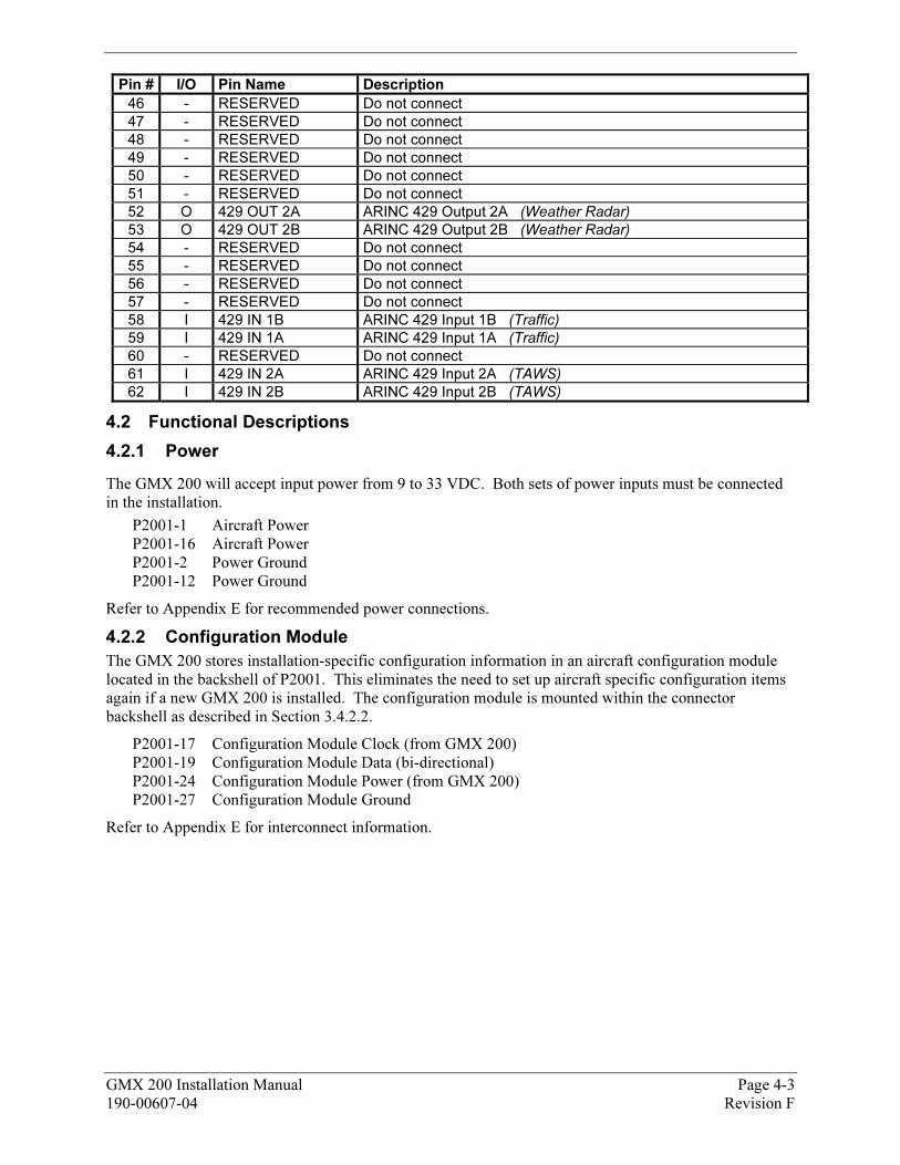
GMX 200 Installation Manual Page 4-3 190-00607-04 Revision F
Pin # I/O Pin Name Description
46 - RESERVED Do not connect
47 - RESERVED Do not connect 48 - RESERVED Do not connect 49 - RESERVED Do not connect 50 - RESERVED Do not connect 51 - RESERVED Do not connect
52 O 429 OUT 2A ARINC 429 Output 2A (Weather Radar)
53 O 429 OUT 2B ARINC 429 Output 2B (Weather Radar)
54 - RESERVED Do not connect
55 - RESERVED Do not connect
56 - RESERVED Do not connect
57 - RESERVED Do not connect
58 I 429 IN 1B ARINC 429 Input 1B (Traffic)
59 I 429 IN 1A ARINC 429 Input 1A (Traffic)
60 - RESERVED Do not connect
61 I 429 IN 2A ARINC 429 Input 2A (TAWS)
62 I 429 IN 2B ARINC 429 Input 2B (TAWS)
4.2 27BFunctional Descriptions
4.2.1 61BPower
The GMX 200 will accept input power from 9 to 33 VDC. Both sets of power inputs must be connected in the installation.
P2001-1 Aircraft Power P2001-16 Aircraft Power P2001-2 Power Ground P2001-12 Power Ground
Refer to XAppendix EX for recommended power connections.
4.2.2 62BConfiguration Module
The GMX 200 stores installation-specific configuration information in an aircraft configuration module located in the backshell of P2001. This eliminates the need to set up aircraft specific configuration items again if a new GMX 200 is installed. The configuration module is mounted within the connector backshell as described in Section X3.4.2.2 X.
P2001-17 Configuration Module Clock (from GMX 200) P2001-19 Configuration Module Data (bi-directional) P2001-24 Configuration Module Power (from GMX 200) P2001-27 Configuration Module Ground
Refer to XAppendix EX for interconnect information.
Page 4-4 GMX 200 Installation Manual Revision F 190-00607-04
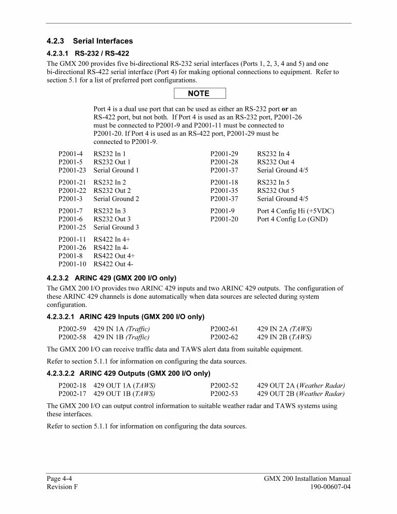
4.2.3 63BSerial Interfaces
4.2.3.1 93BRS-232 / RS-422
The GMX 200 provides five bi-directional RS-232 serial interfaces (Ports 1, 2, 3, 4 and 5) and one bi-directional RS-422 serial interface (Port 4) for making optional connections to equipment. Refer to section X5.1X for a list of preferred port configurations.
NOTE
Port 4 is a dual use port that can be used as either an RS-232 port or an RS-422 port, but not both. If Port 4 is used as an RS-232 port, P2001-26 must be connected to P2001-9 and P2001-11 must be connected to P2001-20. If Port 4 is used as an RS-422 port, P2001-29 must be connected to P2001-9.
P2001-4 RS232 In 1 P2001-29 RS232 In 4 P2001-5 RS232 Out 1 P2001-28 RS232 Out 4 P2001-23 Serial Ground 1 P2001-37 Serial Ground 4/5
P2001-21 RS232 In 2 P2001-18 RS232 In 5 P2001-22 RS232 Out 2 P2001-35 RS232 Out 5 P2001-3 Serial Ground 2 P2001-37 Serial Ground 4/5
P2001-7 RS232 In 3 P2001-9 Port 4 Config Hi (+5VDC) P2001-6 RS232 Out 3 P2001-20 Port 4 Config Lo (GND) P2001-25 Serial Ground 3
P2001-11 RS422 In 4+ P2001-26 RS422 In 4- P2001-8 RS422 Out 4+ P2001-10 RS422 Out 4-
4.2.3.2 94BARINC 429 (GMX 200 I/O only)
The GMX 200 I/O provides two ARINC 429 inputs and two ARINC 429 outputs. The configuration of these ARINC 429 channels is done automatically when data sources are selected during system configuration.
4.2.3.2.1 114BARINC 429 Inputs (GMX 200 I/O only)
P2002-59 429 IN 1A (Traffic) P2002-61 429 IN 2A (TAWS)
P2002-58 429 IN 1B (Traffic) P2002-62 429 IN 2B (TAWS)
The GMX 200 I/O can receive traffic data and TAWS alert data from suitable equipment.
Refer to section X5.1.1X for information on configuring the data sources.
4.2.3.2.2 115BARINC 429 Outputs (GMX 200 I/O only)
P2002-18 429 OUT 1A (TAWS) P2002-52 429 OUT 2A (Weather Radar) P2002-17 429 OUT 1B (TAWS) P2002-53 429 OUT 2B (Weather Radar)
The GMX 200 I/O can output control information to suitable weather radar and TAWS systems using these interfaces.
Refer to section X5.1.1X for information on configuring the data sources.
GMX 200 Installation Manual Page 4-5 190-00607-04 Revision F
4.2.3.3 95BARINC 453/708 Inputs (GMX 200 I/O only)
The GMX 200 I/O provides two ARINC 453/708 inputs. The configuration of these inputs is done automatically when data sources are selected during system configuration.
P2002-40 453/708 IN 1A (Weather Radar) P2002-21 453/708 IN 2A (TAWS) P2002-19 453/708 IN 1B (Weather Radar) P2002-42 453/708 IN 2B (TAWS)
The GMX 200 I/O can receive weather and terrain data from suitable weather radar and TAWS systems.
Refer to section X5.1.1X for information on configuring the data sources.
4.2.4 64BDiscrete Outputs (GMX 200 I/O only)
The GMX 200 I/O provides three discrete outputs. The configuration of these inputs is done automatically when data sources are selected during system configuration.
P2002-5 Discrete Out 1 (Weather Radar) P2002-7 Discrete Out 3 (Traffic)
P2002-6 Discrete Out 2 (Traffic)
The GMX 200 I/O can use these discrete outputs to control suitable traffic and weather radar systems.
Refer to section X5.1.1X for information on configuring the data sources.

Page 4-6 GMX 200 Installation Manual Revision F 190-00607-04
This Page Intentionally Left Blank
GMX 200 Installation Manual Page 5-1 190-00607-04 Revision F
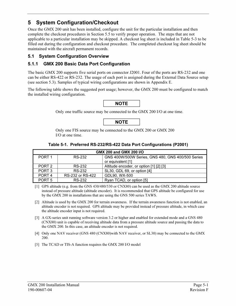
5 4BSystem Configuration/Checkout Once the GMX 200 unit has been installed, configure the unit for the particular installation and then complete the checkout procedures in Section X5.5 X to verify proper operation. The steps that are not applicable to a particular installation may be skipped. A checkout log sheet is included in XTable 5-3X to be filled out during the configuration and checkout procedure. The completed checkout log sheet should be maintained with the aircraft permanent records.
5.1 28BSystem Configuration Overview
5.1.1 65BGMX 200 Basic Data Port Configuration
The basic GMX 200 supports five serial ports on connector J2001. Four of the ports are RS-232 and one can be either RS-422 or RS-232. The usage of each port is assigned during the External Data Source setup (see section X5.3X). Samples of typical wiring configurations are shown in XAppendix EX.
The following table shows the suggested port usage; however, the GMX 200 must be configured to match the installed wiring configuration.
NOTE
Only one traffic source may be connected to the GMX 200 I/O at one time.
NOTE
Only one FIS source may be connected to the GMX 200 or GMX 200 I/O at one time.
Table 5-1. Preferred RS-232/RS-422 Data Port Configurations (P2001)
GMX 200 and GMX 200 I/O
PORT 1 RS-232 GNS 400W/500W Series, GNS 480, GNS 400/500 Series or equivalent [1]
PORT 2 RS-232 Altitude encoder, or option [1] [2] [3]
PORT 3 RS-232 SL30, GDL 69, or option [4]
PORT 4 RS-232 or RS-422 GDL90, WX-500
PORT 5 RS-232 Ryan TCAD, or option [5]
[1] GPS altitude (e.g. from the GNS 430/480/530 or CNX80) can be used as the GMX 200 altitude source
instead of pressure altitude (altitude encoder). It is recommended that GPS altitude be configured for use
by the GMX 200 in installations that are using the GNS 500 series TAWS.
[2] Altitude is used by the GMX 200 for terrain awareness. If the terrain awareness function is not enabled, an
altitude encoder is not required. GPS altitude may be provided instead of pressure altitude, in which case
the altitude encoder input is not required.
[3] A GX-series unit running software version 3.2 or higher and enabled for extended mode and a GNS 480
(CNX80) unit is capable of receiving altitude data from a pressure altitude source and passing the data to
the GMX 200. In this case, an altitude encoder is not required.
[4] Only one NAV receiver (GNS 480 (CNX80)with NAV receiver, or SL30) may be connected to the GMX
200.
[5] The TCAD or TIS-A function requires the GMX 200 I/O model
Page 5-2 GMX 200 Installation Manual Revision F 190-00607-04
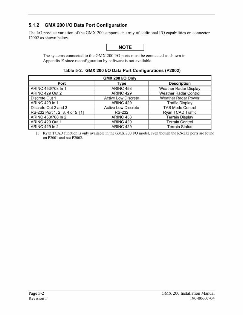
5.1.2 66BGMX 200 I/O Data Port Configuration
The I/O product variation of the GMX 200 supports an array of additional I/O capabilities on connector J2002 as shown below.
NOTE
The systems connected to the GMX 200 I/O ports must be connected as shown in XAppendix EX since reconfiguration by software is not available.
Table 5-2. GMX 200 I/O Data Port Configurations (P2002)
GMX 200 I/O Only
Port Type Description
ARINC 453/708 In 1 ARINC 453 Weather Radar Display
ARINC 429 Out 2 ARINC 429 Weather Radar Control
Discrete Out 1 Active Low Discrete Weather Radar Power
ARINC 429 In 1 ARINC 429 Traffic Display
Discrete Out 2 and 3 Active Low Discrete TAS Mode Control
RS-232 Port 1, 2, 3, 4 or 5 [1] RS-232 Ryan TCAD Traffic
ARINC 453/708 In 2 ARINC 453 Terrain Display
ARINC 429 Out 1 ARINC 429 Terrain Control
ARINC 429 In 2 ARINC 429 Terrain Status
[1] Ryan TCAD function is only available in the GMX 200 I/O model, even though the RS-232 ports are found
on P2001 and not P2002.
5.2 29BPost-Installation Power Check
Verify that all cables are properly secured and shields are connected to the shield block of the connector. Check the movement of the flight and engine controls to verify that there is no interference. Ensure wiring is installed in accordance with AC 43.13-1B, Chapter 11. Verify that the power and ground leads are correct.
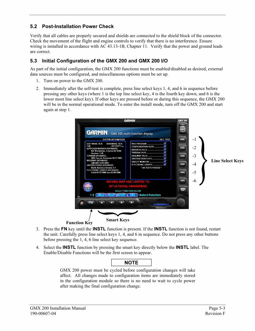
5.3 30BInitial Configuration of the GMX 200 and GMX 200 I/O
As part of the initial configuration, the GMX 200 functions must be enabled/disabled as desired, external data sources must be configured, and miscellaneous options must be set up.
1. Turn on power to the GMX 200.
2. Immediately after the self-test is complete, press line select keys 1, 4, and 6 in sequence before pressing any other keys (where 1 is the top line select key, 4 is the fourth key down, and 6 is the lower most line select key). If other keys are pressed before or during this sequence, the GMX 200 will be in the normal operational mode. To enter the install mode, turn off the GMX 200 and start again at step 1.
-1
-2
-3
-4
-5
-6
Line Select Keys
Smart Keys Function Key
3. Press the FN key until the INSTL function is present. If the INSTL function is not found, restart the unit. Carefully press line select keys 1, 4, and 6 in sequence. Do not press any other buttons before pressing the 1, 4, 6 line select key sequence.
4. Select the INSTL function by pressing the smart key directly below the INSTL label. The Enable/Disable Functions will be the first screen to appear.
NOTE
GMX 200 power must be cycled before configuration changes will take affect. All changes made to configuration items are immediately stored in the configuration module so there is no need to wait to cycle power after making the final configuration change.
GMX 200 Installation Manual Page 5-3 190-00607-04 Revision F
NOTE
The following sections describe all available configuration options. Depending upon the model of GMX 200 being installed, the described options may or may not be available for a particular unit.
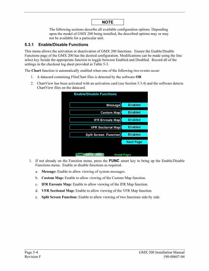
5.3.1 67BEnable/Disable Functions
This menu allows the activation or deactivation of GMX 200 functions. Ensure the Enable/Disable Functions page of the GMX 200 has the desired configuration. Modifications can be made using the line select key beside the appropriate function to toggle between Enabled and Disabled. Record all of the settings in the checkout log sheet provided in XTable 5-3X.
The Chart function is automatically enabled when one of the following two events occur:
1. A datacard containing FliteChart files is detected by the software OR
2. ChartView has been activated with an activation card (see Section X5.3.4X) and the software detects ChartView files on the datacard.
1. If not already on the Function menu, press the FUNC smart key to bring up the Enable/Disable Functions menu. Enable or disable functions as required.
a. Message: Enable to allow viewing of system messages.
b. Custom Map: Enable to allow viewing of the Custom Map function.
c. IFR Enroute Map: Enable to allow viewing of the IFR Map function.
d. VFR Sectional Map: Enable to allow viewing of the VFR Map function.
e. Split Screen Function: Enable to allow viewing of two functions side by side.
Page 5-4 GMX 200 Installation Manual Revision F 190-00607-04
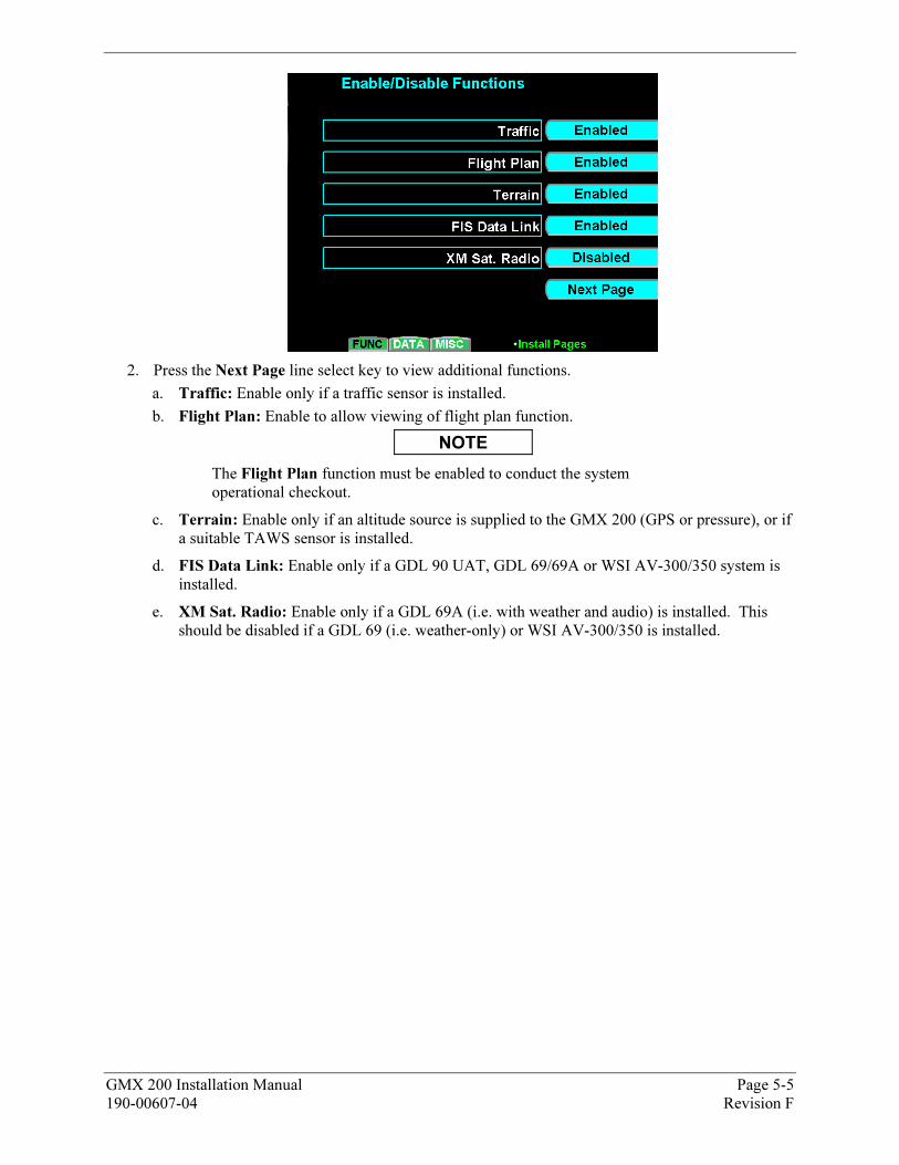
2. Press the Next Page line select key to view additional functions.
a. Traffic: Enable only if a traffic sensor is installed.
b. Flight Plan: Enable to allow viewing of flight plan function.
NOTE
The Flight Plan function must be enabled to conduct the system operational checkout.
c. Terrain: Enable only if an altitude source is supplied to the GMX 200 (GPS or pressure), or if a suitable TAWS sensor is installed.
d. FIS Data Link: Enable only if a GDL 90 UAT, GDL 69/69A or WSI AV-300/350 system is installed.
e. XM Sat. Radio: Enable only if a GDL 69A (i.e. with weather and audio) is installed. This should be disabled if a GDL 69 (i.e. weather-only) or WSI AV-300/350 is installed.
GMX 200 Installation Manual Page 5-5 190-00607-04 Revision F
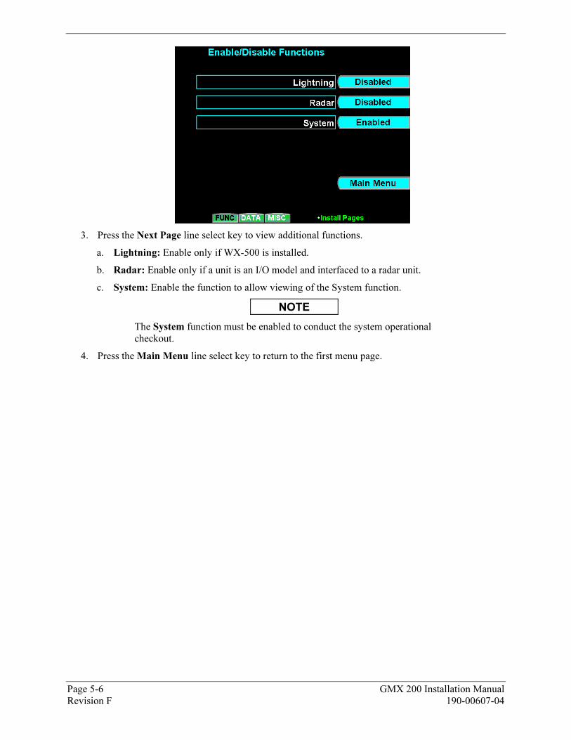
3. Press the Next Page line select key to view additional functions.
a. Lightning: Enable only if WX-500 is installed.
b. Radar: Enable only if a unit is an I/O model and interfaced to a radar unit.
c. System: Enable the function to allow viewing of the System function.
NOTE
The System function must be enabled to conduct the system operational checkout.
4. Press the Main Menu line select key to return to the first menu page.
Page 5-6 GMX 200 Installation Manual Revision F 190-00607-04
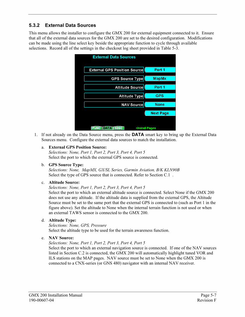
5.3.2 68BExternal Data Sources
This menu allows the installer to configure the GMX 200 for external equipment connected to it. Ensure that all of the external data sources for the GMX 200 are set to the desired configuration. Modifications can be made using the line select key beside the appropriate function to cycle through available selections. Record all of the settings in the checkout log sheet provided in XTable 5-3X.
1. If not already on the Data Source menu, press the DATA smart key to bring up the External Data Sources menu. Configure the external data sources to match the installation.
a. External GPS Position Source: Selections: None, Port 1, Port 2, Port 3, Port 4, Port 5
Select the port to which the external GPS source is connected.
b. GPS Source Type: Selections: None, MapMX, GX/SL Series, Garmin Aviation, B/K KLN90B Select the type of GPS source that is connected. Refer to Section XC.1 X.
c. Altitude Source:
Selections: None, Port 1, Port 2, Port 3, Port 4, Port 5
Select the port to which an external altitude source is connected. Select None if the GMX 200 does not use any altitude. If the altitude data is supplied from the external GPS, the Altitude Source must be set to the same port that the external GPS is connected to (such as Port 1 in the figure above). Set the altitude to None when the internal terrain function is not used or when an external TAWS sensor is connected to the GMX 200.
d. Altitude Type: Selections: None, GPS, Pressure Select the altitude type to be used for the terrain awareness function.
e. NAV Source:
Selections: None, Port 1, Port 2, Port 3, Port 4, Port 5
Select the port to which an external navigation source is connected. If one of the NAV sources listed in Section C.2 is connected, the GMX 200 will automatically highlight tuned VOR and ILS stations on the MAP pages. NAV source must be set to None when the GMX 200 is connected to a CNX-series (or GNS 480) navigator with an internal NAV receiver.
GMX 200 Installation Manual Page 5-7 190-00607-04 Revision F

2. Press the Next Page line select key to view additional data source selections.
a. Lightning Source:
Selections: None, Port 1, Port 2, Port 3, Port 4, Port 5
Select the port to which a lightning source is connected.
b. UAT Source: Selections: None, Port 1, Port 2, Port 3, Port 4, Port 5
Select the port to which a UAT is connected.
c. Ryan TCAD Source: Selections: None, Port 1, Port 2, Port 3, Port 4, Port 5
Select the port to which a Ryan TCAD is connected.
d. Traffic Source (429): Selections: None, TAS, TAS+Disp
Select the port to which an ARINC 429 traffic source is connected. If the GMX 200 is wired to drive the traffic system discrete inputs and control the traffic system, select the TAS option. If the GMX 200 is not wired to drive the discrete inputs (e.g. when an additional traffic display such as the WX1000 is being used), select the TAS+DISP option. Using the TAS+DISP option indicates that an external display is responsible for driving the discrete inputs and the corresponding GMX 200 controls will be disabled on the GMX 200 Traffic page.
NOTE
Only one traffic source may be present (i.e. For UAT Source, Ryan TCAD Source Traffic Source (429) and Transponder TIS Source, only one may be configured for an external data source – the others must be set to None.)
e. Transponder TIS Source: Selections: None, GTX 330
Select the type of TIS source that is connected. Select GTX330 if a GTX 33 is connected to the GMX 200.
Page 5-8 GMX 200 Installation Manual Revision F 190-00607-04
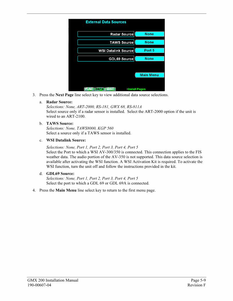
3. Press the Next Page line select key to view additional data source selections.
a. Radar Source:
Selections: None, ART-2000, RS-181, GWX 68, RS-811A
Select source only if a radar sensor is installed. Select the ART-2000 option if the unit is wired to an ART-2100.
b. TAWS Source: Selections: None, TAWS8000, KGP 560 Select a source only if a TAWS sensor is installed.
c. WSI Datalink Source:
Selections: None, Port 1, Port 2, Port 3, Port 4, Port 5
Select the Port to which a WSI AV-300/350 is connected. This connection applies to the FIS weather data. The audio portion of the AV-350 is not supported. This data source selection is available after activating the WSI function. A WSI Activation Kit is required. To activate the WSI function, turn the unit off and follow the instructions provided in the kit.
d. GDL69 Source: Selections: None, Port 1, Port 2, Port 3, Port 4, Port 5
Select the port to which a GDL 69 or GDL 69A is connected.
4. Press the Main Menu line select key to return to the first menu page.
GMX 200 Installation Manual Page 5-9 190-00607-04 Revision F
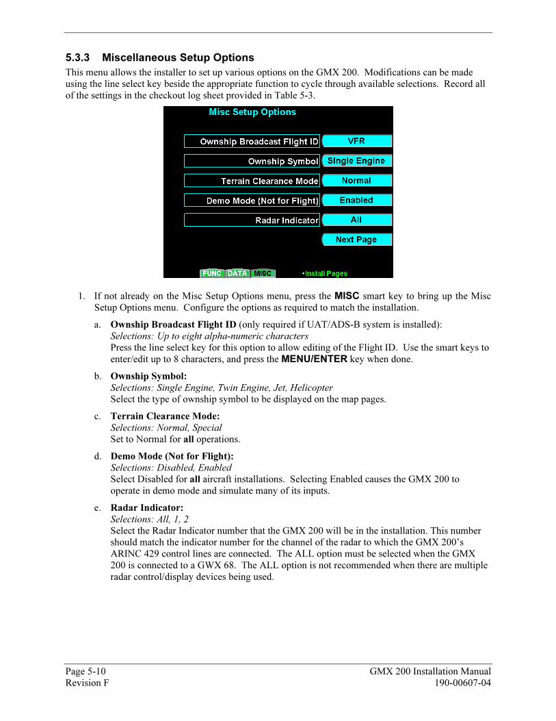
5.3.3 69BMiscellaneous Setup Options
This menu allows the installer to set up various options on the GMX 200. Modifications can be made using the line select key beside the appropriate function to cycle through available selections. Record all of the settings in the checkout log sheet provided in XTable 5-3X.
1. If not already on the Misc Setup Options menu, press the MISC smart key to bring up the Misc Setup Options menu. Configure the options as required to match the installation.
a. Ownship Broadcast Flight ID (only required if UAT/ADS-B system is installed): Selections: Up to eight alpha-numeric characters
Press the line select key for this option to allow editing of the Flight ID. Use the smart keys to enter/edit up to 8 characters, and press the MENU/ENTER key when done.
b. Ownship Symbol: Selections: Single Engine, Twin Engine, Jet, Helicopter
Select the type of ownship symbol to be displayed on the map pages.
c. Terrain Clearance Mode: Selections: Normal, Special
Set to Normal for all operations.
d. Demo Mode (Not for Flight): Selections: Disabled, Enabled
Select Disabled for all aircraft installations. Selecting Enabled causes the GMX 200 to operate in demo mode and simulate many of its inputs.
e. Radar Indicator: Selections: All, 1, 2
Select the Radar Indicator number that the GMX 200 will be in the installation. This number should match the indicator number for the channel of the radar to which the GMX 200’s ARINC 429 control lines are connected. The ALL option must be selected when the GMX 200 is connected to a GWX 68. The ALL option is not recommended when there are multiple radar control/display devices being used.
Page 5-10 GMX 200 Installation Manual Revision F 190-00607-04
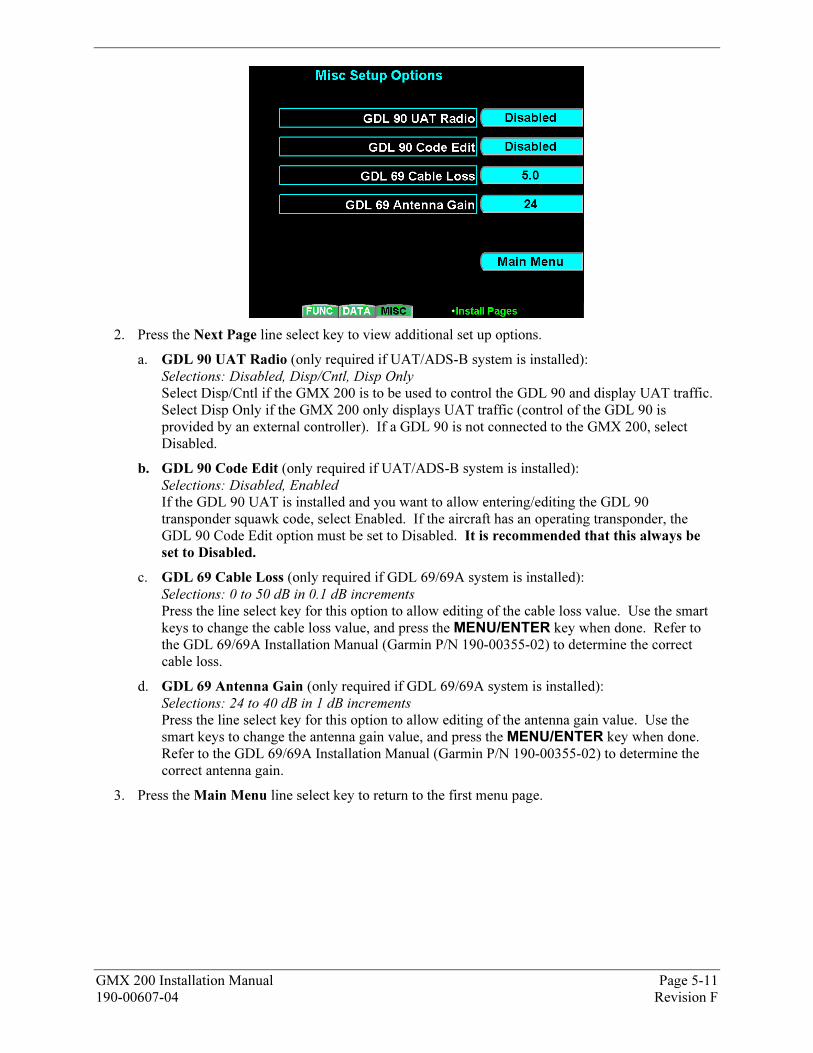
2. Press the Next Page line select key to view additional set up options.
a. GDL 90 UAT Radio (only required if UAT/ADS-B system is installed): Selections: Disabled, Disp/Cntl, Disp Only
Select Disp/Cntl if the GMX 200 is to be used to control the GDL 90 and display UAT traffic. Select Disp Only if the GMX 200 only displays UAT traffic (control of the GDL 90 is provided by an external controller). If a GDL 90 is not connected to the GMX 200, select Disabled.
b. GDL 90 Code Edit (only required if UAT/ADS-B system is installed): Selections: Disabled, Enabled If the GDL 90 UAT is installed and you want to allow entering/editing the GDL 90 transponder squawk code, select Enabled. If the aircraft has an operating transponder, the GDL 90 Code Edit option must be set to Disabled. It is recommended that this always be
set to Disabled.
c. GDL 69 Cable Loss (only required if GDL 69/69A system is installed): Selections: 0 to 50 dB in 0.1 dB increments
Press the line select key for this option to allow editing of the cable loss value. Use the smart keys to change the cable loss value, and press the MENU/ENTER key when done. Refer to the GDL 69/69A Installation Manual (Garmin P/N 190-00355-02) to determine the correct cable loss.
d. GDL 69 Antenna Gain (only required if GDL 69/69A system is installed): Selections: 24 to 40 dB in 1 dB increments
Press the line select key for this option to allow editing of the antenna gain value. Use the smart keys to change the antenna gain value, and press the MENU/ENTER key when done. Refer to the GDL 69/69A Installation Manual (Garmin P/N 190-00355-02) to determine the correct antenna gain.
3. Press the Main Menu line select key to return to the first menu page.
GMX 200 Installation Manual Page 5-11 190-00607-04 Revision F
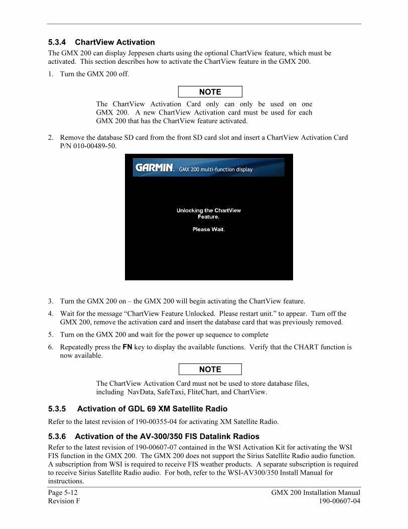
5.3.4 70BChartView Activation
The GMX 200 can display Jeppesen charts using the optional ChartView feature, which must be activated. This section describes how to activate the ChartView feature in the GMX 200.
1. Turn the GMX 200 off.
NOTE
The ChartView Activation Card only can only be used on one GMX 200. A new ChartView Activation card must be used for each GMX 200 that has the ChartView feature activated.
2. Remove the database SD card from the front SD card slot and insert a ChartView Activation Card P/N 010-00489-50.
3. Turn the GMX 200 on – the GMX 200 will begin activating the ChartView feature.
4. Wait for the message “ChartView Feature Unlocked. Please restart unit.” to appear. Turn off the GMX 200, remove the activation card and insert the database card that was previously removed.
5. Turn on the GMX 200 and wait for the power up sequence to complete
6. Repeatedly press the FN key to display the available functions. Verify that the CHART function is now available.
NOTE
The ChartView Activation Card must not be used to store database files, including NavData, SafeTaxi, FliteChart, and ChartView.
5.3.5 71BActivation of GDL 69 XM Satellite Radio
Refer to the latest revision of 190-00355-04 for activating XM Satellite Radio.
5.3.6 72BActivation of the AV-300/350 FIS Datalink Radios
Refer to the latest revision of 190-00607-07 contained in the WSI Activation Kit for activating the WSI FIS function in the GMX 200. The GMX 200 does not support the Sirius Satellite Radio audio function. A subscription from WSI is required to receive FIS weather products. A separate subscription is required to receive Sirius Satellite Radio audio. For both, refer to the WSI-AV300/350 Install Manual for instructions.
Page 5-12 GMX 200 Installation Manual Revision F 190-00607-04
GMX 200 Installation Manual Page 5-13 190-00607-04 Revision F
NOTE
The ChartView Activation Card must not be used to store database files, including NavData, SafeTaxi, FliteChart, and ChartView.
5.4 31BExternal Device Setup, Configuration and Calibration
All procedures in this section assume that the GMX 200 has been configured for the applicable external data sources. The original documentation for the external sensors describes how to calibrate the sensor using another display – this section describes how those procedures are modified if the GMX 200 display is used instead.
5.4.1 73BRADAR Configuration, Calibration and Checkout Procedures
The following steps are performed to verify the interface between the RADAR sensor and the GMX 200 I/O. The radome should NOT be installed during these tests as visual verification of antenna movement is required.
Note that the Antenna Receiver/Transmitter should be installed and calibrated in accordance with the manufacturer’s specifications. This manual does not cover the installation or calibration of the actual ART unit.
WARNING
Configuration procedures include steps that require the radar antenna to be powered on. Please observe all safety precautions during these steps including: Do not perform in the vicinity of refueling operations; Do not perform while personnel are in the vicinity (approximately 20 feet) of the radar sweep area.
NOTE
See FAA AC20-68B “Recommended Radiation Safety Precautions For Airborne Weather Radar” for safety precautions to be taken by personnel when operating airborne weather radar on the ground.
5.4.1.1 96BART 2000 Calibration Procedures Using GMX 200
Refer to the Bendix/King ART2000 Color Weather Radar System Installation Manual, Revision 4 or later. Follow the instructions in "Stabilization calibration with Radar Indicator" or its equivalent.
Skip the description in the ART2000 manual on how to enter calibration mode. The GMX 200 allows a single button push to enter calibration mode. The GMX 200 MUST be in Install mode to calibrate the radar head. Follow the instructions below.
1. Turn the GMX 200 on.
2. After boot-up is complete, key-in the install sequence 1, 4, 6, on the line select keys to enter the Install mode.
3. Press the FN key until one of the smart key options is RADAR. If the RADAR option is not available, ensure that the GMX 200 is configured for a radar source.
4. Press the smart key corresponding to the RADAR option. You will now switch to the Radar page.
5. Press the STBY/ON line select key on the GMX 200 to put the radar unit into standby mode. This may take up to twenty seconds.
6. Once the radar is in standby mode, one of the menu options will be TEST. Press the TEST key.
7. Once the GMX 200 is in Test mode, press the MENU/ENT key to switch to the Setup page.
Page 5-14 GMX 200 Installation Manual Revision F 190-00607-04
8. On the Setup page, press the line select key labeled CALB to enter calibration mode. This will take a few seconds.
9. The GMX 200 will flash all faults briefly and the text near the bottom of the display will read “Calibration Enabled” to indicate calibration mode has been entered. If this fails, turn power off and try again.
At this point, follow directions in the ART2000 Installation Manual starting with "400 Hz Ref Gain" section. Selection of calibration parameters is done by adjusting the gain setting according to the values in the ART2000 Installation Manual. On the GMX 200, the "smart keys" labeled "Gain" are used to adjust the gain setting and select the parameter to be calibrated. Follow the ART2000 Installation Manual instructions for calibrating the selected parameters.
5.4.1.2 97BGWX 68 Calibration Procedure Using the GMX 200
The following procedure covers both analog and ARINC 429 stabilization inputs. If one or the other input is not available, that particular option need not be calibrated.
Calibration parameters are stored in the GWX 68 configuration module (not the GMX 200 configuration module). When replacing a GWX 68, an error message will be displayed indicating the configuration data in the GWX 68 does not match the data in the configuration module. Perform the Save Configuration procedure in Section X5.4.1.2.7X to load the configuration data from the Configuration Module into the GWX 68. When the data from the Configuration Module is saved in the GWX 68, recalibration of the radar is not necessary.
If an analog stabilization input is used, the radar stabilization source must be removed from the aircraft and mounted on a tilt table for proper calibration.
Analog stabilization values for pitch and roll can only be adjusted if the GWX 68 is provided with a 400 Hz reference input.
The GMX 200 must be in the Install mode to calibrate the radar head. Follow the instructions below:
1. Turn the GMX 200 on.
2. After boot-up is complete, key-in the install sequence 1, 4, 6, on the line select keys to enter the Install mode.
3. Press the FN key until one of the smart key options is RADAR. If the RADAR option is not available, ensure that the GMX 200 is configured for a radar source.
4. Press the smart key corresponding to the RADAR option. You will now switch to the Radar page.
5. Press the STBY line select key on the GMX 200 to put the radar unit into standby mode. This may take up to twenty seconds.
6. Once the radar is in standby mode, one of the menu options will be TEST. Press the TEST key.
7. Once the GMX 200 is in Test mode, press the MENU/ENT key to switch to the Setup page.
8. On the Setup page, press the key labeled CALB to enter calibration mode. This will take a few seconds.
9. The GMX 200 will flash all faults briefly and the text near the bottom of the display will read “Calibration Enabled” to indicate calibration mode has been entered. If this fails, turn power off and try again.
If the only stabilization source is ARINC 429, proceed directly to Section X5.4.1.2.7 X. No adjustment is needed for ARINC 429 input from an AHRS since it is assumed the AHRS was previously calibrated for level attitude.
GMX 200 Installation Manual Page 5-15 190-00607-04 Revision F
5.4.1.2.1 116BCalibration of Analog Stabilization Inputs
When in Calibration mode, the GWX 68 is ready to calibrate the stabilization inputs. Each parameter can be calibrated as described in the sections below.
The GAIN adjustment is used to select the parameter being calibrated. The TILT adjustment is used to adjust the parameter’s value.
5.4.1.2.2 117B400HZ Reference Gain
1. Set the tilt table to 0° pitch and roll.
2. Use the GAIN + and GAIN – keys to set the GAIN to -28. The AZIMUTH ANGLE field should also display 01.
3. Use the TILT � and TILT � keys to adjust the TILT SETTING. A TILT SETTING between 5 UP and 10 UP increases the 400 HZ REF field, while a TILT SETTING between 5 DOWN and 10
DOWN decreases the 400 HZ REF field. Use the TILT keys to set the 400 HZ REF field to 0.0 ±
1.0°. Upon reaching the desired 400 HZ REF setting, quickly set the TILT SETTING to between 5 UP and 5 DOWN to lock in the 400 HZ REF setting.
5.4.1.2.3 118BPitch Offset
1. Check that the tilt table is set for 0° pitch.
2. Use the GAIN + and GAIN – keys to set the GAIN to between -17.5 and -19.5. The AZIMUTH ANGLE field should also display 04. Note that the pitch offset value is displayed in the PITCH ANGLE field.
3. Use the TILT � and TILT � keys to adjust the TILT SETTING. A TILT SETTING between 5 UP and 10 UP increases the PITCH ANGLE field, while a TILT SETTING between 5 DOWN and 10 DOWN decreases the PITCH ANGLE field. Use the TILT keys to set the PITCH ANGLE field to
0.0 ± 1.0°. Upon reaching the desired PITCH ANGLE setting, quickly set the TILT SETTING to between 5 UP and 5 DOWN to lock in the PITCH ANGLE setting.
5.4.1.2.4 119BRoll Offset
1. Check that the tilt table is set for 0° roll.
2. Use the GAIN + and GAIN – keys to set the GAIN to between -14 and -16. The AZIMUTH ANGLE field should also display 05. Note that the roll offset value is displayed in the ROLL ANGLE field.
3. Use the TILT � and TILT � keys to adjust the TILT SETTING. A TILT SETTING between 5 UP and 10 UP increases the ROLL ANGLE field, while a TILT SETTING between 5 DOWN and 10 DOWN decreases the ROLL ANGLE field. Use the TILT keys to set the ROLL ANGLE field to 0.0
± 1.0°. Upon reaching the desired ROLL ANGLE setting, quickly set the TILT SETTING to between 5 UP and 5 DOWN to lock in the ROLL ANGLE setting.
5.4.1.2.5 120BPitch Gain
1. Set the tilt table for 10° pitch up.
2. Use the GAIN + and GAIN – keys to set the GAIN to between -24.5 and -26.5. The AZIMUTH ANGLE field should also display 02. Note that the pitch gain value is displayed in the PITCH ANGLE field.
3. Use the TILT � and TILT � keys to adjust the TILT SETTING. A TILT SETTING between 5 UP and 10 UP increases the PITCH ANGLE field, while a TILT SETTING between 5 DOWN and 10 DOWN decreases the PITCH ANGLE field. Use the TILT keys to set the PITCH ANGLE field to
10.0 ± 1.0°. Upon reaching the desired PITCH ANGLE setting, quickly set the TILT SETTING to between 5 UP and 5 DOWN to lock in the PITCH ANGLE setting.
Page 5-16 GMX 200 Installation Manual Revision F 190-00607-04
4. Set the tilt table to 10° pitch down. The PITCH ANGLE value should be 10.0D ± 1.0°. If the value is out of range, repeat steps in Sections X5.4.1.2.3X and X5.4.1.2.5X (this section).
5. Set the tilt table to 0° pitch. The PITCH ANGLE value should be 0.0 ± 1.0°. If the value is out of range, repeat steps in Sections X5.4.1.2.3X and X5.4.1.2.5X (this section).
5.4.1.2.6 121BRoll Gain
1. Set the tilt table for 10° roll right.
2. Use the GAIN + and GAIN – keys to set the GAIN to between -21 and -23. The AZIMUTH ANGLE field should also display 03. Note that the roll gain value is displayed in the ROLL ANGLE field.
3. Use the TILT � and TILT � keys to adjust the TILT SETTING. A TILT SETTING between 5 UP and 10 UP increases the ROLL ANGLE field, while a TILT SETTING between 5 DOWN and 10 DOWN decreases the ROLL ANGLE field. Use the TILT keys to set the ROLL ANGLE field to
10.0 ± 1.0°. Upon reaching the desired ROLL ANGLE setting, quickly set the TILT SETTING to between 5 UP and 5 DOWN to lock in the ROLL ANGLE setting.
4. Set the tilt table to 10° roll left. The ROLL ANGLE value should be 10.0L ± 1.0°. If the value is out of range, repeat steps in Sections X5.4.1.2.4X and X5.4.1.2.6X (this section).
5. Set the tilt table to 0° roll. The ROLL ANGLE value should be 0.0 ± 1.0°. If the value is out of range, repeat steps in Sections X5.4.1.2.4X and X5.4.1.2.6X (this section).
5.4.1.2.7 122BSave Configuration
1. Use the GAIN + and GAIN – keys to set the GAIN to between -3.5and -5.5. The AZIMUTH ANGLE field should also display 08.
2. Set the TILT SETTING to 15.0D. The fault fields will flash on indicating the save procedure is beginning. If the save procedure is successful, the GYRO fault will disappear.
3. If the GYRO remains unchanged, adjust the TILT SETTING to 0° and repeat step 2.
5.4.1.2.8 123BRoll Trim Adjustment
This procedure must be performed in flight with an operational, transmitting radar. This procedure should be performed over flat terrain or water if possible.
1. Turn the GMX 200 on.
2. After boot-up is complete, key-in the install sequence 1, 4, 6, on the smart keys.
3. Press the FN key until one of the smart key options is RADAR.
4. Press the smart key corresponding to the RADAR option.
5. Press the STBY key to put the radar unit into standby mode. This may take up to twenty seconds.
6. Press the key labeled ON. The radar will enter WX mode and begin transmitting.
7. Adjust the range and tilt controls so that ground returns are painted past approximately half of the selected range.
8. Press they key labeled STBY. The radar will return to standby mode.
9. Once the GWX 68 is in standby mode, press the TEST key.
10. Once the GWX 68 is in Test mode, press the ENTER key to switch to the Setup page.
11. On the Setup page, press the key labeled CALB to enter calibration mode. This will take a few seconds.
12. The GMX 200 will flash all faults briefly to indicate calibration mode has been entered. If this fails, turn power off and on and repeat the procedure.
GMX 200 Installation Manual Page 5-17 190-00607-04 Revision F
13. Press the line select key labeled ROLL TRIM.
14. Acknowledge the safety warning that appears. The radar will begin transmitting.
15. Adjust the roll trim setting until the range at which ground returns begin remains approximately constant across a full scan of the display.
16. Press the key labeled SAVE & EXIT. Power cycle the GMX 200.
5.4.1.3 98BRS 181A Calibration Procedures Using GMX 200
Refer to the Bendix/King RDS 82 Color Weather Radar System Installation Manual. Follow the instructions in "Stabilization calibration with Radar Indicator" or its equivalent.
Skip the description in the RDS 82 manual on how to enter calibration mode. The GMX 200 allows a single button push to enter calibration mode. The GMX 200 MUST be in Install mode to calibrate the radar head. Follow the instructions below.
1. Turn the GMX 200 on.
2. After boot-up is complete, key-in the install sequence 1, 4, 6, on the line select keys to enter the Install mode.
3. Press the FN key until one of the smart key options is RADAR. If the RADAR option is not available, ensure that the GMX 200 is configured for a radar source.
4. Press the smart key corresponding to the RADAR option. You will now switch to the Radar page.
5. Press the STBY/ON line select key on the GMX 200 to put the radar unit into standby mode. This may take up to twenty seconds.
6. Once the radar is in standby mode, one of the menu options will be TEST. Press the TEST key.
7. Once the GMX 200 is in Test mode, press the MENU/ENT key to switch to the Setup page.
8. On the Setup page, press the line select key labeled CALB to enter calibration mode. This will take a few seconds.
9. The GMX 200 will flash all faults briefly and the text near the bottom of the display will read “Calibration Enabled” to indicate calibration mode has been entered. If this fails, turn power off and try again.
10. From here you may follow the manufacturer’s calibration instructions and procedure or set the roll/trim parameter. Remember that the antenna is radiating during the setting of roll/trim.
11. To return to Test mode and the test-pattern display, press the MENU/ENTER key. Once you return to test mode, calibration mode is disabled.
Page 5-18 GMX 200 Installation Manual Revision F 190-00607-04
5.4.1.4 99BRS 811A Calibration Procedures Using GMX 200
Refer to the Bendix/King RDS 81 Color Weather Radar System Installation Manual. Follow the instructions in "Antenna Stabilization Check and Calibration in the Aircraft" or its equivalent.
Skip the description in the RDS 81 manual on how to enter calibration mode and the “hidden page”. The GMX 200 allows a single button push to enter calibration mode. The GMX 200 MUST be in Install mode to calibrate the radar head. Follow the instructions below.
1. Turn the GMX 200 on.
2. After boot-up is complete, key-in the install sequence 1, 4, 6, on the line select keys to enter the Install mode.
3. Press the FN key until one of the smart key options is RADAR. If the RADAR option is not available, ensure that the GMX 200 is configured for a radar source.
4. Press the smart key corresponding to the RADAR option. You will now switch to the Radar page.
5. Press the STBY/ON line select key on the GMX 200 to put the radar unit into standby mode. This may take up to twenty seconds.
6. Once the radar is in standby mode, one of the menu options will be TEST. Press the TEST key.
7. Once the GMX 200 is in Test mode, press the MENU/ENT key to switch to the Setup page.
8. On the Setup page, press the line select key labeled CALB to enter calibration mode. This will take a few seconds.
9. The GMX 200 will flash all faults briefly and the text near the bottom of the display will read “Calibration Enabled” to indicate calibration mode has been entered. If this fails, turn power off and try again.
10. From here you may follow the manufacturer’s calibration instructions and procedure or set the roll/trim parameter. Remember that the antenna is radiating during the setting of roll/trim.
11. To return to Test mode and the test-pattern display, press the MENU/ENTER key. Once you return to test mode, calibration mode is disabled.
5.4.2 74BActivation of GDL 69 XM Satellite Radio
Refer to the latest revision of 190-00355-04 for activating XM Satellite Radio.
5.5 32BSystem Operational Checkout
NOTE
Prior to proceeding with the operational checkout, the GMX 200 power must be cycled for any configuration changes to take effect.
NOTE
Throughout the checkout section references are made to particular GMX 200 functions. If the function is not available, ensure that the GMX 200 has been configured correctly as described in Section X5.3X.
5.5.1 75BSoftware and Database Test
1. Turn on power to the GMX 200.
2. Verify all self-tests pass on the main startup screen.
3. Verify the expiration on the Jeppeson NavData Database.
4. If activated, verify the expiration of the Electronic Charts Database.
5. Press the MSG smart key and verify that “Unit configured for Special Terrain Mode” is NOT displayed.
GMX 200 Installation Manual Page 5-19 190-00607-04 Revision F
5.5.2 76BGeneral Serial Data Source Tests
Verify that all external serial interfaces are configured correctly and providing data to the GMX 200.
1. Turn on power to the GMX 200 and all external data sources connected to it.
2. Check the Info page under the System (SYS) function and verify that each of the serial ports is configured correctly for the installation by looking at the corresponding entry in the ‘Port’ column: NONE indicates that the port is not configured to receive data.
3. Verify that the data is available to each configured serial port by looking at the corresponding entry in the ‘Data?’ column: YES indicates data is present, NO indicates data is not present, and ‘---‘ indicates that the port is not configured.
NOTE
Some data sources (e.g. altitude encoder) require a warm-up period before outputting valid data. During the warm-up period data may be flagged as invalid.
4. Before proceeding, ensure that all of the serial data is valid by looking at the corresponding entry in the ‘Valid?’ column: YES indicates data is valid, NO indicates data is not valid, and ‘---‘ indicates that the port is not configured.
5.5.3 77BGPS Navigation Source Interface Test
The GMX 200 can receive position and flight plan data from an external GPS Navigation source. If a GNS 480 is used as the external navigation source, the GMX 200 and GNS 480 can also share baro-correction data. This check verifies that the units are communicating.
1. Ensure that the external GPS Navigation is turned on and verify that the GPS Navigation source acquires a position.
2. Create/activate a flight plan on the GPS navigation source.
3. Verify the RTE and POS data flags are not displayed on the GMX 200.
4. Verify that the flight plan is displayed on the GMX 200 using the flight plan (FPL) function.
NOTE
For installations with a GNS 480 (CNX80) GPS source, the GMX 200 and GNS 480 can share baro-correction data. If the GMX 200 is configured for MapMX, Pressure altitude, and no external TAWS Source, the following step must be performed.
Page 5-20 GMX 200 Installation Manual Revision F 190-00607-04
5. If the GNS 480 is configured for BARO POT: NOT INSTALLED, verify that the baro-correction on the GMX 200 and GNS 480 are the same. Change the baro-correction on the SYS Nav page of the GMX 200 and verify that it changes on the GNS 480.
5.5.4 78BAltitude Source Interface Test
The GMX 200 can receive altitude data from a GPS Navigation sensor (pressure or GPS altitude) or an altitude encoder (pressure altitude). This check verifies that the GMX 200 is configured correctly and is receiving altitude data.
NOTE
If the GMX 200 is configured for an external TAWS Source, altitude will not be displayed.
5.5.4.1 100BGPS Altitude Source
1. Ensure that the GPS Navigation Source has acquired a position.
2. Verify that the amber ALT flag is not displayed.
3. Select the MAP function and verify that GPS Alt: is displayed, along with a valid altitude.
GMX 200 Installation Manual Page 5-21 190-00607-04 Revision F
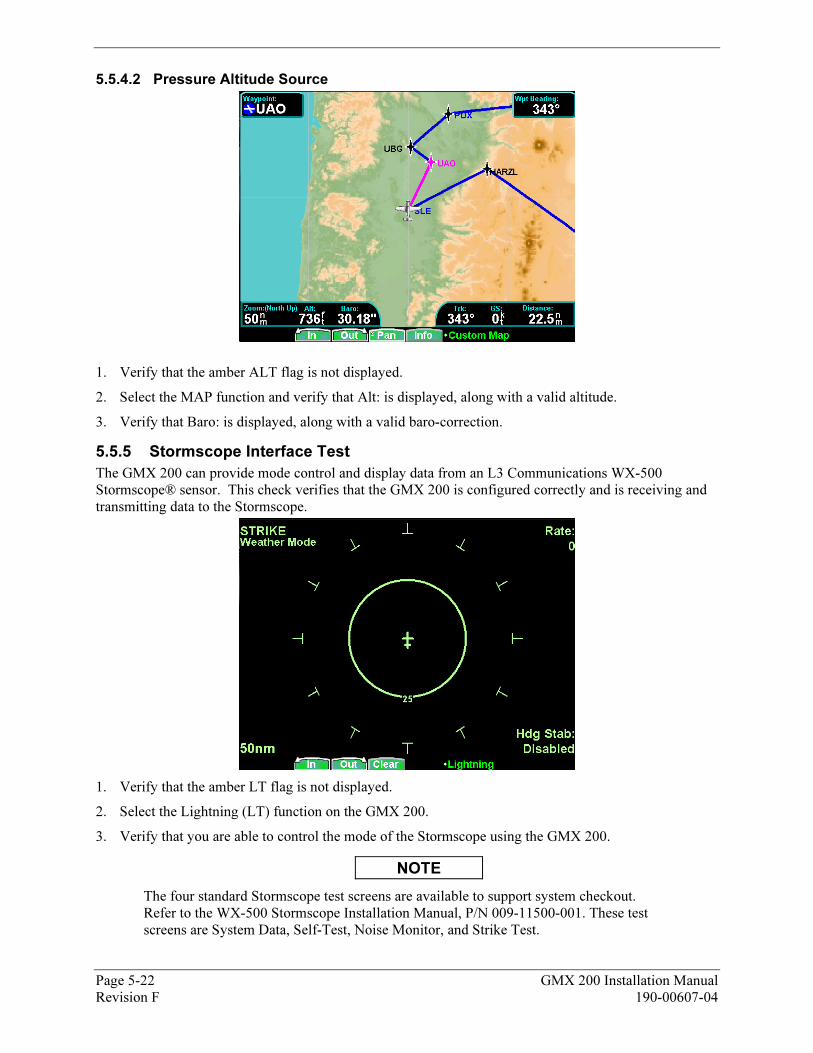
5.5.4.2 101BPressure Altitude Source
1. Verify that the amber ALT flag is not displayed.
2. Select the MAP function and verify that Alt: is displayed, along with a valid altitude.
3. Verify that Baro: is displayed, along with a valid baro-correction.
5.5.5 79BStormscope Interface Test
The GMX 200 can provide mode control and display data from an L3 Communications WX-500 Stormscope® sensor. This check verifies that the GMX 200 is configured correctly and is receiving and transmitting data to the Stormscope.
1. Verify that the amber LT flag is not displayed.
2. Select the Lightning (LT) function on the GMX 200.
3. Verify that you are able to control the mode of the Stormscope using the GMX 200.
NOTE
The four standard Stormscope test screens are available to support system checkout. Refer to the WX-500 Stormscope Installation Manual, P/N 009-11500-001. These test screens are System Data, Self-Test, Noise Monitor, and Strike Test.
Page 5-22 GMX 200 Installation Manual Revision F 190-00607-04
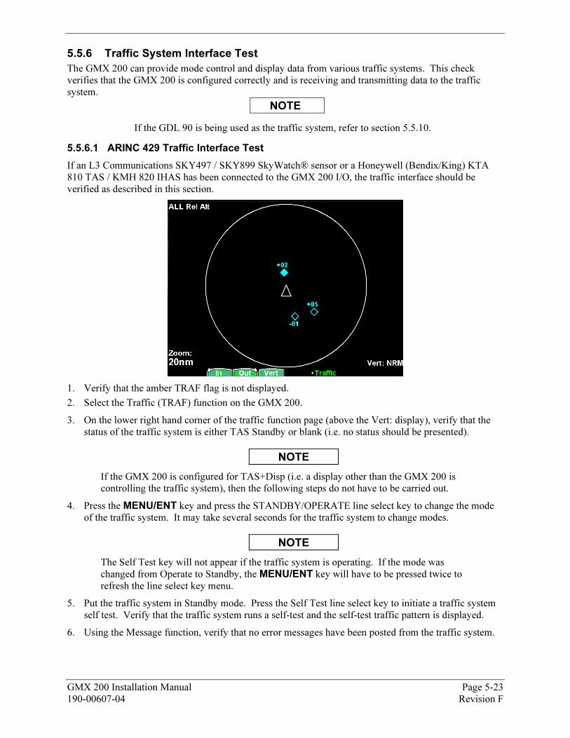
5.5.6 80BTraffic System Interface Test
The GMX 200 can provide mode control and display data from various traffic systems. This check verifies that the GMX 200 is configured correctly and is receiving and transmitting data to the traffic system.
NOTE
If the GDL 90 is being used as the traffic system, refer to section X5.5.10X.
5.5.6.1 102BARINC 429 Traffic Interface Test
If an L3 Communications SKY497 / SKY899 SkyWatch® sensor or a Honeywell (Bendix/King) KTA 810 TAS / KMH 820 IHAS has been connected to the GMX 200 I/O, the traffic interface should be verified as described in this section.
1. Verify that the amber TRAF flag is not displayed.
2. Select the Traffic (TRAF) function on the GMX 200.
3. On the lower right hand corner of the traffic function page (above the Vert: display), verify that the status of the traffic system is either TAS Standby or blank (i.e. no status should be presented).
NOTE
If the GMX 200 is configured for TAS+Disp (i.e. a display other than the GMX 200 is controlling the traffic system), then the following steps do not have to be carried out.
4. Press the MENU/ENT key and press the STANDBY/OPERATE line select key to change the mode of the traffic system. It may take several seconds for the traffic system to change modes.
NOTE
The Self Test key will not appear if the traffic system is operating. If the mode was changed from Operate to Standby, the MENU/ENT key will have to be pressed twice to refresh the line select key menu.
5. Put the traffic system in Standby mode. Press the Self Test line select key to initiate a traffic system self test. Verify that the traffic system runs a self-test and the self-test traffic pattern is displayed.
6. Using the Message function, verify that no error messages have been posted from the traffic system.
GMX 200 Installation Manual Page 5-23 190-00607-04 Revision F
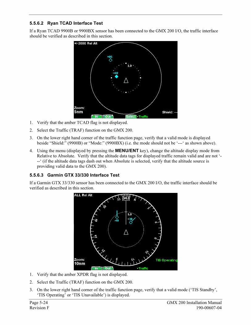
5.5.6.2 103BRyan TCAD Interface Test
If a Ryan TCAD 9900B or 9900BX sensor has been connected to the GMX 200 I/O, the traffic interface should be verified as described in this section.
1. Verify that the amber TCAD flag is not displayed.
2. Select the Traffic (TRAF) function on the GMX 200.
3. On the lower right hand corner of the traffic function page, verify that a valid mode is displayed beside “Shield:” (9900B) or “Mode:” (9900BX) (i.e. the mode should not be ‘---‘ as shown above).
4. Using the menu (displayed by pressing the MENU/ENT key), change the altitude display mode from Relative to Absolute. Verify that the altitude data tags for displayed traffic remain valid and are not ‘---‘ (if the altitude data tags dash out when Absolute is selected, verify that the altitude source is providing valid data to the GMX 200).
5.5.6.3 104BGarmin GTX 33/330 Interface Test
If a Garmin GTX 33/330 sensor has been connected to the GMX 200 I/O, the traffic interface should be verified as described in this section.
1. Verify that the amber XPDR flag is not displayed.
2. Select the Traffic (TRAF) function on the GMX 200.
3. On the lower right hand corner of the traffic function page, verify that a valid mode (‘TIS Standby’, ‘TIS Operating’ or ‘TIS Unavailable’) is displayed.
Page 5-24 GMX 200 Installation Manual Revision F 190-00607-04
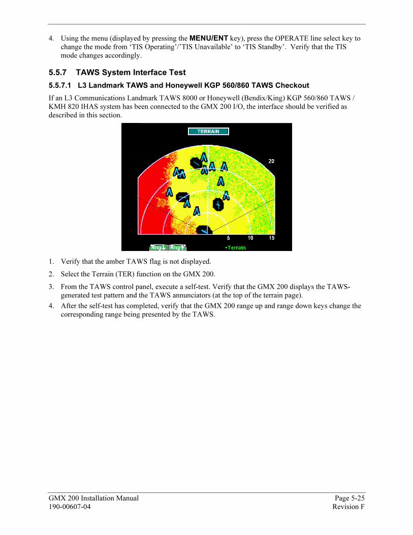
4. Using the menu (displayed by pressing the MENU/ENT key), press the OPERATE line select key to change the mode from ‘TIS Operating’/’TIS Unavailable’ to ‘TIS Standby’. Verify that the TIS mode changes accordingly.
5.5.7 81BTAWS System Interface Test
5.5.7.1 105BL3 Landmark TAWS and Honeywell KGP 560/860 TAWS Checkout
If an L3 Communications Landmark TAWS 8000 or Honeywell (Bendix/King) KGP 560/860 TAWS / KMH 820 IHAS system has been connected to the GMX 200 I/O, the interface should be verified as described in this section.
1. Verify that the amber TAWS flag is not displayed.
2. Select the Terrain (TER) function on the GMX 200.
3. From the TAWS control panel, execute a self-test. Verify that the GMX 200 displays the TAWS-generated test pattern and the TAWS annunciators (at the top of the terrain page).
4. After the self-test has completed, verify that the GMX 200 range up and range down keys change the corresponding range being presented by the TAWS.
GMX 200 Installation Manual Page 5-25 190-00607-04 Revision F
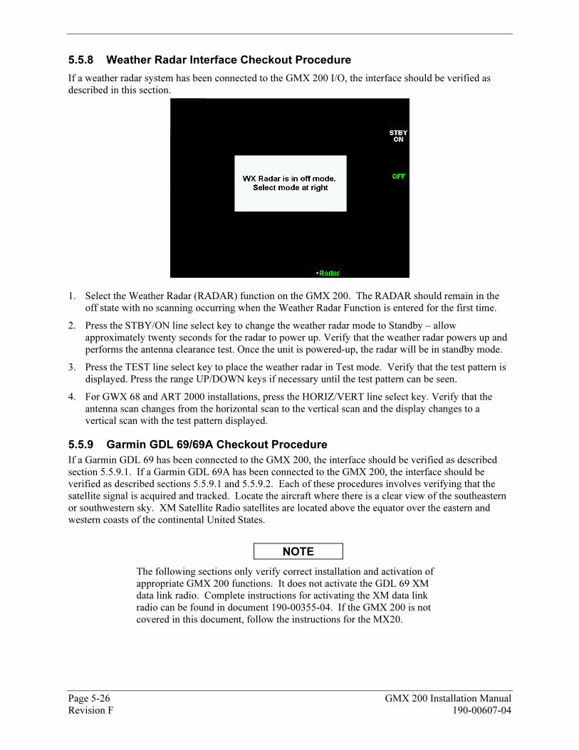
5.5.8 82BWeather Radar Interface Checkout Procedure
If a weather radar system has been connected to the GMX 200 I/O, the interface should be verified as described in this section.
1. Select the Weather Radar (RADAR) function on the GMX 200. The RADAR should remain in the off state with no scanning occurring when the Weather Radar Function is entered for the first time.
2. Press the STBY/ON line select key to change the weather radar mode to Standby – allow approximately twenty seconds for the radar to power up. Verify that the weather radar powers up and performs the antenna clearance test. Once the unit is powered-up, the radar will be in standby mode.
3. Press the TEST line select key to place the weather radar in Test mode. Verify that the test pattern is displayed. Press the range UP/DOWN keys if necessary until the test pattern can be seen.
4. For GWX 68 and ART 2000 installations, press the HORIZ/VERT line select key. Verify that the antenna scan changes from the horizontal scan to the vertical scan and the display changes to a vertical scan with the test pattern displayed.
5.5.9 83BGarmin GDL 69/69A Checkout Procedure
If a Garmin GDL 69 has been connected to the GMX 200, the interface should be verified as described section X5.5.9.1 X. If a Garmin GDL 69A has been connected to the GMX 200, the interface should be verified as described sections X5.5.9.1X and X5.5.9.2X. Each of these procedures involves verifying that the satellite signal is acquired and tracked. Locate the aircraft where there is a clear view of the southeastern or southwestern sky. XM Satellite Radio satellites are located above the equator over the eastern and western coasts of the continental United States.
NOTE
The following sections only verify correct installation and activation of appropriate GMX 200 functions. It does not activate the GDL 69 XM data link radio. Complete instructions for activating the XM data link radio can be found in document 190-00355-04. If the GMX 200 is not covered in this document, follow the instructions for the MX20.
Page 5-26 GMX 200 Installation Manual Revision F 190-00607-04
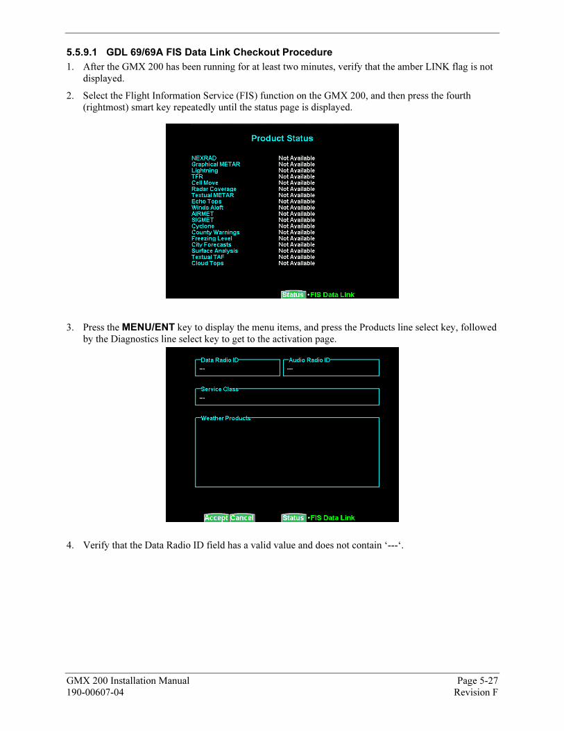
5.5.9.1 106BGDL 69/69A FIS Data Link Checkout Procedure
1. After the GMX 200 has been running for at least two minutes, verify that the amber LINK flag is not displayed.
2. Select the Flight Information Service (FIS) function on the GMX 200, and then press the fourth (rightmost) smart key repeatedly until the status page is displayed.
3. Press the MENU/ENT key to display the menu items, and press the Products line select key, followed by the Diagnostics line select key to get to the activation page.
4. Verify that the Data Radio ID field has a valid value and does not contain ‘---‘.
GMX 200 Installation Manual Page 5-27 190-00607-04 Revision F
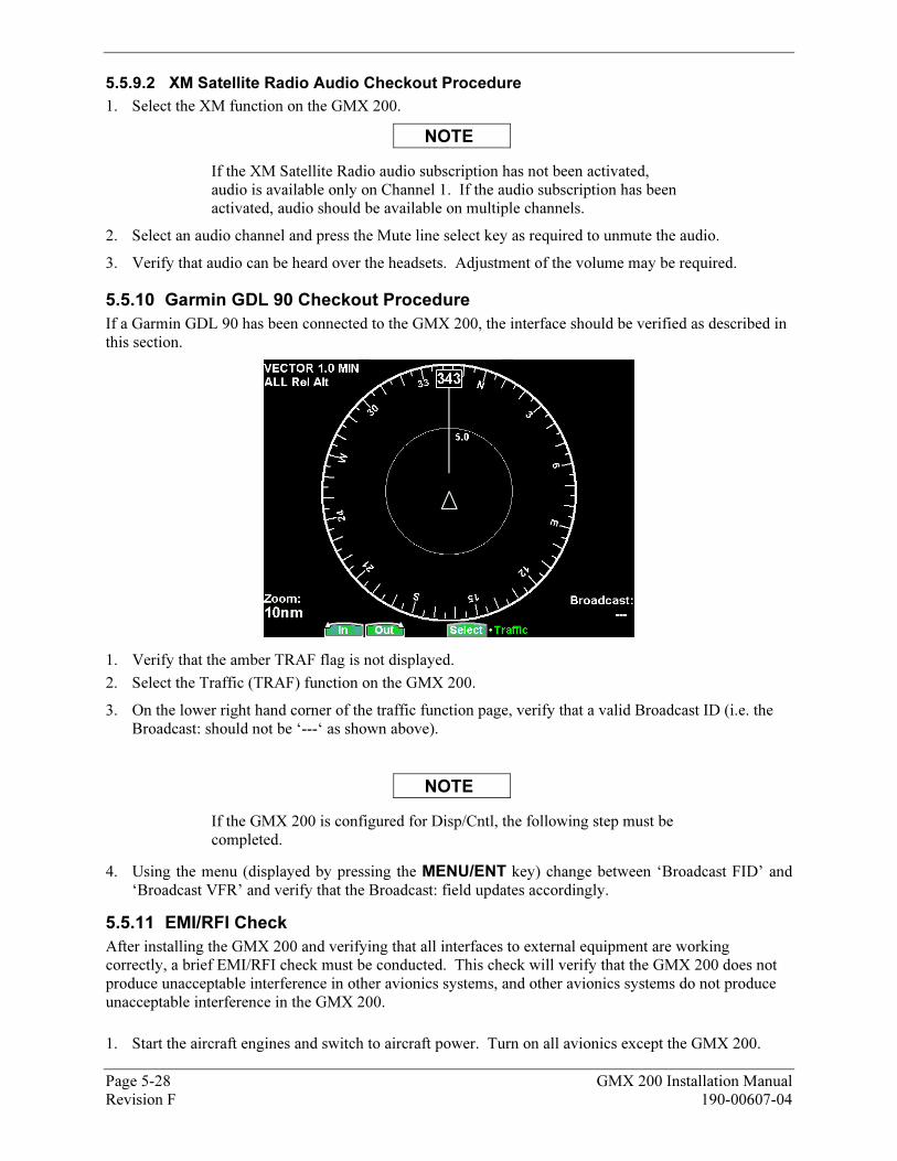
5.5.9.2 107BXM Satellite Radio Audio Checkout Procedure
1. Select the XM function on the GMX 200.
NOTE
If the XM Satellite Radio audio subscription has not been activated, audio is available only on Channel 1. If the audio subscription has been activated, audio should be available on multiple channels.
2. Select an audio channel and press the Mute line select key as required to unmute the audio.
3. Verify that audio can be heard over the headsets. Adjustment of the volume may be required.
5.5.10 84BGarmin GDL 90 Checkout Procedure
If a Garmin GDL 90 has been connected to the GMX 200, the interface should be verified as described in this section.
1. Verify that the amber TRAF flag is not displayed.
2. Select the Traffic (TRAF) function on the GMX 200.
3. On the lower right hand corner of the traffic function page, verify that a valid Broadcast ID (i.e. the Broadcast: should not be ‘---‘ as shown above).
NOTE
If the GMX 200 is configured for Disp/Cntl, the following step must be completed.
4. Using the menu (displayed by pressing the MENU/ENT key) change between ‘Broadcast FID’ and ‘Broadcast VFR’ and verify that the Broadcast: field updates accordingly.
5.5.11 85BEMI/RFI Check
After installing the GMX 200 and verifying that all interfaces to external equipment are working correctly, a brief EMI/RFI check must be conducted. This check will verify that the GMX 200 does not produce unacceptable interference in other avionics systems, and other avionics systems do not produce unacceptable interference in the GMX 200.
1. Start the aircraft engines and switch to aircraft power. Turn on all avionics except the GMX 200.
Page 5-28 GMX 200 Installation Manual Revision F 190-00607-04

GMX 200 Installation Manual Page 5-29 190-00607-04 Revision F
2. With the GMX 200 switched off, verify that all existing avionics systems are functioning properly.
3. Turn the GMX 200 on and remove power from all other avionics systems.
NOTE
Removing power from systems interfaced to the GMX 200 will cause the associated system flags on the GMX 200 to be displayed. This is normal behavior and does not constitute a test failure.
4. Apply power to the other avionics systems one at a time and verify that the system is functioning properly without any unacceptable interference caused by the GMX 200. Ensure that there is no unacceptable interference in the GMX 200 when the avionic system is powered up. Wait for the system to begin functioning normally before applying power to the next system.
5.5.12 86BWSI AV-300/350 Checkout Procedure
The checkout procedure to verify proper FIS datalink sensor operation with the GMX 200 is the same for the WSI AV-300 or AV-350 sensor. The GMX 200 supports the weather datalink portion and not the audio portion of the AV-350. This procedure may be conducted in a hangar as it verifies proper serial communication between the FIS sensor and the GMX 200. The WSI antenna requires a clear view of the sky towards the south to verify satellite signal reception.
NOTE
This procedure verifies correct installation and operation of the GMX 200 FIS function and wiring between the GMX 200 and WSI AV-300 or AV-350 FIS sensor. It does not activate WSI weather products or the Sirius Satellite Radio audio function. Instructions for activating the WSI or Sirius Satellite Radio provided features can be found in the WSI AV-300/350 Installation Manual.
1. Apply power to the AV-300/350 and wait a minimum of 3 minutes, 15 seconds.
2. Turn on the GMX 200 and wait for the startup screen to appear. The GMX 200 must be started after the AV-300/350 has finished its startup sequence to ensure proper operation.
3. After the GMX 200 has been running for two minutes, verify that the LINK flag is not displayed. Refer to Section 6, Troubleshooting if the flag appears. The flag is an indication that the GMX 200 is not receiving data from the AV-300/350.
4. Select the Flight Information Service (FIS) function on the GMX 200.
5. Press the MENU/ENT key.
6. Press the Status Menu Option Key.
7. Press the Stats Smart key.
8. Verify that the Receiver ID matches the ID on the AV-300/350 label. The ID number appears as two alternating portions of the whole ID number.
9. This concludes the checkout procedure.
The Stats and Prod pages can be used to observe AV-300/350 operation of the FIS function. Verification of the audio function cannot be performed with the GMX 200.
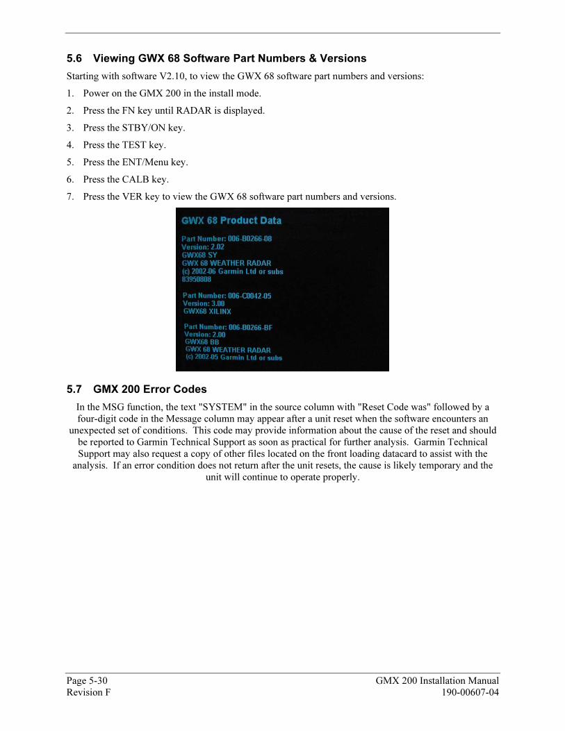
5.6 33BViewing GWX 68 Software Part Numbers & Versions
Starting with software V2.10, to view the GWX 68 software part numbers and versions:
1. Power on the GMX 200 in the install mode.
2. Press the FN key until RADAR is displayed.
3. Press the STBY/ON key.
4. Press the TEST key.
5. Press the ENT/Menu key.
6. Press the CALB key.
7. Press the VER key to view the GWX 68 software part numbers and versions.
5.7 34BGMX 200 Error Codes
In the MSG function, the text "SYSTEM" in the source column with "Reset Code was" followed by a four-digit code in the Message column may appear after a unit reset when the software encounters an
unexpected set of conditions. This code may provide information about the cause of the reset and should be reported to Garmin Technical Support as soon as practical for further analysis. Garmin Technical Support may also request a copy of other files located on the front loading datacard to assist with the
analysis. If an error condition does not return after the unit resets, the cause is likely temporary and the unit will continue to operate properly.
Page 5-30 GMX 200 Installation Manual Revision F 190-00607-04
GMX 200 Installation Manual Page 5-31 190-00607-04 Revision F
Table 5-3. GMX 200 Series Post-Installation Checkout Log
GMX 200 Post-Installation Checkout Log
Date: ____ /____ /____
By: ________________
INSTALLATION
INFORMATION: Aircraft Model ______________________ Aircraft Serial # ______________
GMX 200 P/N ________________________________ Mod Level __________
GMX 200 Model ________________________ Serial # _________________
CONFIGURATION ITEMS:
Enable/Disable Functions (FUNC) External Data Sources (DATA)
Message: � Enabled � Disabled External GPS Pos’n Source: � None � Port ____
Custom Map: � Enabled � Disabled GPS Source Type: ___________________
IFR Enroute Map: � Enabled � Disabled Altitude Source: � None � Port ____
VFR Sectional Map: � Enabled � Disabled Altitude Type: � None � GPS � Pressure
Split Screen Function: � Enabled � Disabled NAV Source: � None � Port ____
Traffic: � Enabled � Disabled Lightning Source: � None � Port ____
Flight Plan: � Enabled � Disabled UAT Source: � None � Port ____
Terrain: � Enabled � Disabled Ryan TCAD Source � None � Port ____
FIS Data Link: � Enabled � Disabled Traffic Source (429) � None � TAS � TAS+Disp
XM Sat. Radio: � Enabled � Disabled Transponder TIS Source: � None � GTX 330
Lightning: � Enabled � Disabled Radar Source: � None � ________________
Radar: � Enabled � Disabled TAWS Source: � None � ________________
System: � Enabled � Disabled WSI Datalink Source � None � Port__ GDL69 Source: � None � Port ____
Miscellaneous Setup Options (MISC) Optional Items
Ownship Broadcast Flight ID: ________________ ChartView Activated: � Yes � No
Ownship Symbol: _________________________
Terrain Clearance Mode: Normal
Demo Mode (Not for Flight): Disabled
Radar Indicator: � All � 1 � 2
GDL 90 UAT Radio: � Disp+Ctrl � Disp Only � Disabled
GDL Code Edit: Disabled
GDL 69 Cable Loss: ___________ dB
GDL 69 Antenna Gain: ___________ dB
After completing configuration and prior to checkout, restart unit for changes to take effect
Page 1 of 2
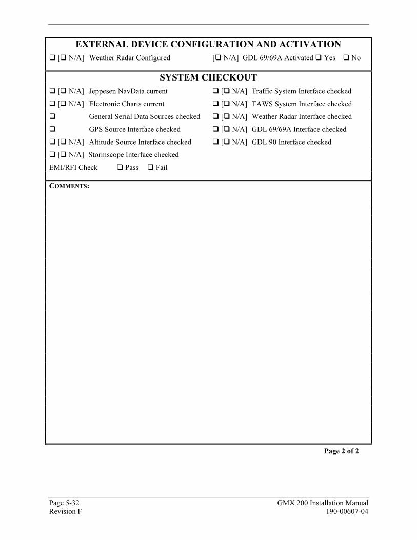
Page 5-32 GMX 200 Installation Manual Revision F 190-00607-04
EXTERNAL DEVICE CONFIGURATION AND ACTIVATION
� [� N/A] Weather Radar Configured [� N/A] GDL 69/69A Activated � Yes � No
SYSTEM CHECKOUT
� [� N/A] Jeppesen NavData current � [� N/A] Traffic System Interface checked
� [� N/A] Electronic Charts current � [� N/A] TAWS System Interface checked
� General Serial Data Sources checked � [� N/A] Weather Radar Interface checked
� GPS Source Interface checked � [� N/A] GDL 69/69A Interface checked
� [� N/A] Altitude Source Interface checked � [� N/A] GDL 90 Interface checked
� [� N/A] Stormscope Interface checked
EMI/RFI Check � Pass � Fail
COMMENTS:
Page 2 of 2
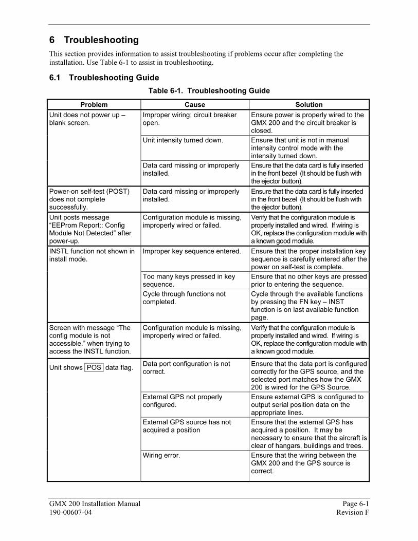
GMX 200 Installation Manual Page 6-1 190-00607-04 Revision F
6 5BTroubleshooting
This section provides information to assist troubleshooting if problems occur after completing the installation. Use XTable 6-1 X to assist in troubleshooting.
6.1 35BTroubleshooting Guide
Table 6-1. Troubleshooting Guide
Problem Cause Solution
Unit does not power up – blank screen.
Improper wiring; circuit breaker open.
Ensure power is properly wired to the GMX 200 and the circuit breaker is closed.
Unit intensity turned down. Ensure that unit is not in manual intensity control mode with the intensity turned down.
Data card missing or improperly installed.
Ensure that the data card is fully inserted in the front bezel (It should be flush with the ejector button).
Power-on self-test (POST) does not complete successfully.
Data card missing or improperly installed.
Ensure that the data card is fully inserted in the front bezel (It should be flush with the ejector button).
Unit posts message “EEProm Report:: Config Module Not Detected” after power-up.
Configuration module is missing, improperly wired or failed.
Verify that the configuration module is properly installed and wired. If wiring is OK, replace the configuration module with a known good module.
INSTL function not shown in install mode.
Improper key sequence entered. Ensure that the proper installation key sequence is carefully entered after the power on self-test is complete.
Too many keys pressed in key sequence.
Ensure that no other keys are pressed prior to entering the sequence.
Cycle through functions not completed.
Cycle through the available functions by pressing the FN key – INST function is on last available function page.
Screen with message “The config module is not accessible.” when trying to access the INSTL function.
Configuration module is missing, improperly wired or failed.
Verify that the configuration module is properly installed and wired. If wiring is OK, replace the configuration module with a known good module.
Unit shows POS data flag. Data port configuration is not correct.
Ensure that the data port is configured correctly for the GPS source, and the selected port matches how the GMX 200 is wired for the GPS Source.
External GPS not properly configured.
Ensure external GPS is configured to output serial position data on the appropriate lines.
External GPS source has not acquired a position
Ensure that the external GPS has acquired a position. It may be necessary to ensure that the aircraft is clear of hangars, buildings and trees.
Wiring error. Ensure that the wiring between the GMX 200 and the GPS source is correct.
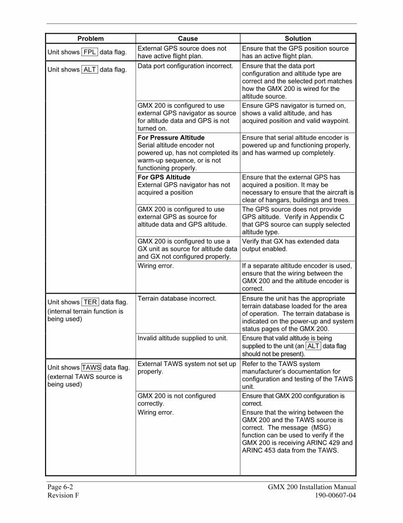
Page 6-2 GMX 200 Installation Manual Revision F 190-00607-04
Problem Cause Solution
Unit shows FPL data flag. External GPS source does not have active flight plan.
Ensure that the GPS position source has an active flight plan.
Unit shows ALT data flag. Data port configuration incorrect. Ensure that the data port
configuration and altitude type are correct and the selected port matches how the GMX 200 is wired for the altitude source.
GMX 200 is configured to use external GPS navigator as source for altitude data and GPS is not turned on.
Ensure GPS navigator is turned on, shows a valid altitude, and has acquired position and valid waypoint.
For Pressure Altitude Serial altitude encoder not powered up, has not completed its warm-up sequence, or is not functioning properly.
Ensure that serial altitude encoder is powered up and functioning properly, and has warmed up completely.
For GPS Altitude External GPS navigator has not acquired a position
Ensure that the external GPS has acquired a position. It may be necessary to ensure that the aircraft is clear of hangars, buildings and trees.
GMX 200 is configured to use external GPS as source for altitude data and GPS altitude.
The GPS source does not provide GPS altitude. Verify in XAppendix CX that GPS source can supply selected altitude type.
GMX 200 is configured to use a GX unit as source for altitude data and GX not configured properly.
Verify that GX has extended data output enabled.
Wiring error. If a separate altitude encoder is used, ensure that the wiring between the GMX 200 and the altitude encoder is correct.
Unit shows TER data flag.
(internal terrain function is being used)
Terrain database incorrect. Ensure the unit has the appropriate terrain database loaded for the area of operation. The terrain database is indicated on the power-up and system status pages of the GMX 200.
Invalid altitude supplied to unit. Ensure that valid altitude is being
supplied to the unit (an ALT data flag
should not be present).
Unit shows TAWS data flag.
(external TAWS source is being used)
External TAWS system not set up properly.
Refer to the TAWS system manufacturer’s documentation for configuration and testing of the TAWS unit.
GMX 200 is not configured correctly.
Ensure that GMX 200 configuration is correct.
Wiring error. Ensure that the wiring between the GMX 200 and the TAWS source is correct. The message (MSG) function can be used to verify if the GMX 200 is receiving ARINC 429 and ARINC 453 data from the TAWS.
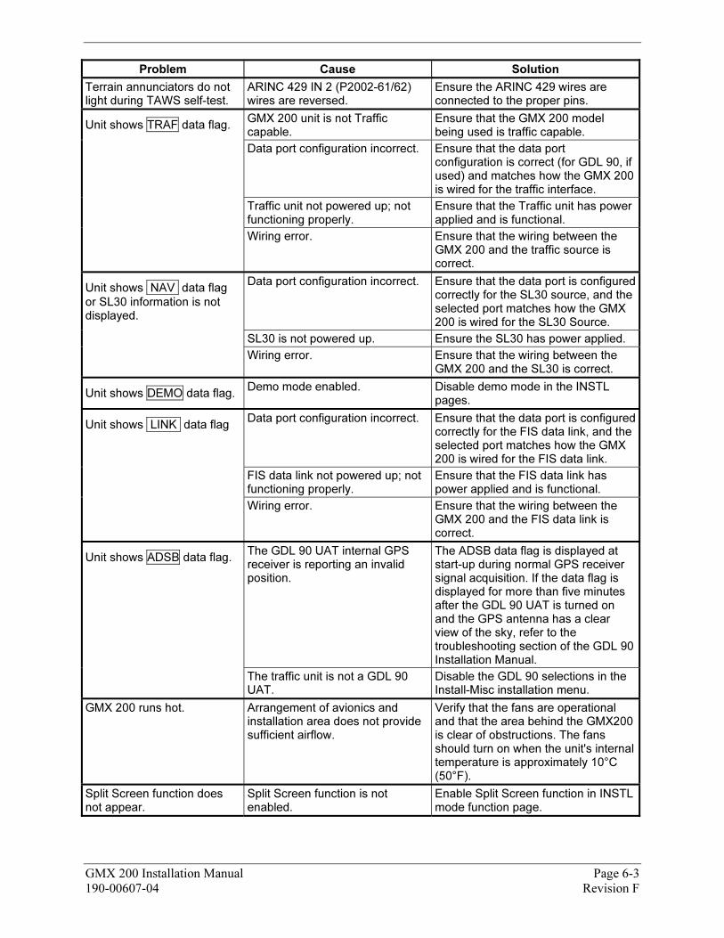
GMX 200 Installation Manual Page 6-3 190-00607-04 Revision F
Problem Cause Solution
Terrain annunciators do not light during TAWS self-test.
ARINC 429 IN 2 (P2002-61/62) wires are reversed.
Ensure the ARINC 429 wires are connected to the proper pins.
Unit shows TRAF data flag. GMX 200 unit is not Traffic capable.
Ensure that the GMX 200 model being used is traffic capable.
Data port configuration incorrect. Ensure that the data port configuration is correct (for GDL 90, if used) and matches how the GMX 200 is wired for the traffic interface.
Traffic unit not powered up; not functioning properly.
Ensure that the Traffic unit has power applied and is functional.
Wiring error. Ensure that the wiring between the GMX 200 and the traffic source is correct.
Unit shows NAV data flag
or SL30 information is not displayed.
Data port configuration incorrect. Ensure that the data port is configured correctly for the SL30 source, and the selected port matches how the GMX 200 is wired for the SL30 Source.
SL30 is not powered up. Ensure the SL30 has power applied.
Wiring error. Ensure that the wiring between the GMX 200 and the SL30 is correct.
Unit shows DEMO data flag. Demo mode enabled. Disable demo mode in the INSTL
pages.
Unit shows LINK data flag Data port configuration incorrect. Ensure that the data port is configured
correctly for the FIS data link, and the selected port matches how the GMX 200 is wired for the FIS data link.
FIS data link not powered up; not functioning properly.
Ensure that the FIS data link has power applied and is functional.
Wiring error. Ensure that the wiring between the GMX 200 and the FIS data link is correct.
Unit shows ADSB data flag. The GDL 90 UAT internal GPS receiver is reporting an invalid position.
The ADSB data flag is displayed at start-up during normal GPS receiver signal acquisition. If the data flag is displayed for more than five minutes after the GDL 90 UAT is turned on and the GPS antenna has a clear view of the sky, refer to the troubleshooting section of the GDL 90 Installation Manual.
The traffic unit is not a GDL 90 UAT.
Disable the GDL 90 selections in the Install-Misc installation menu.
GMX 200 runs hot. Arrangement of avionics and installation area does not provide sufficient airflow.
Verify that the fans are operational and that the area behind the GMX200 is clear of obstructions. The fans should turn on when the unit's internal temperature is approximately 10°C (50°F).
Split Screen function does not appear.
Split Screen function is not enabled.
Enable Split Screen function in INSTL mode function page.
Page 6-4 GMX 200 Installation Manual Revision F 190-00607-04
Problem Cause Solution
Unit posts message indicating ‘Special’ terrain clearance mode after power-up.
Terrain clearance mode not set to Normal.
General aviation usage should have the terrain mode set to ‘Normal’ in the install pages.
Unit shows IDENT (Green) This is not a problem. This is an indication that the GDL 90 UAT is in Identification mode. This should be a temporary indication.
No action required.
Unit show RDR (Solid Green) This is not a problem. This is an indication that the weather radar is on and broadcasting energy.
No action required.
Unit shows RDR (Flashing Green)
This is not a problem. This is an indication that the weather radar is in the Hold mode and broadcasting energy.
No action required.
6.2 36BContacting the Factory for Assistance
If the GMX 200 fails to operate despite troubleshooting efforts, contact Customer Service for assistance.
GARMIN International, Inc. 1200 East 151st Street Olathe, KS 66062-3426 USA Phone: 913 397 8200 FAX: 913 397 8282 http://www.garmin.com
Be prepared to offer the following information about the installation:
• Installation configuration (accessories, antenna, ...)
• Model number, part number with mod levels, and serial number
• Software version
• Description of problem
• Efforts made to isolate the problem
GMX 200 Installation Manual Page 7-1 190-00607-04 Revision F
7 6BLimitations
7.1 37BOperation
There are no Part 23 aircraft type limitations. All functions of the GMX 200 meet the appropriate design assurance qualifications for a secondary system for airplanes in Class I, Class II, Class III, and Class IV in accordance with AC 23.1309-1C, Figure 2. The TSO authorizations with the RTCA/DO178B software levels by function are listed in Section X1.6X.
7.2 38BInstallation
The conditions and tests required for TSO approval of this article are minimum performance standards. It is the responsibility of those installing this article either on or within a specific type or class of aircraft to determine that the aircraft installation conditions are within the TSO standards. TSO articles must have separate approval for installation in an aircraft. The article may be installed only if performed under 14 CFR Part 43 or the applicable airworthiness requirements.
If it is necessary to move any required instrumentation in an instrument panel to make room for the GMX 200, although the physical mounting of the GMX 200 is covered within this installation manual, the relocation of these instruments is beyond the scope of the STC.
For installations where a 6.25” wide radio structure of adequate height is not already approved in the aircraft, a separate structural approval is needed for installation of such supporting structure, prior to installing the GMX 200. Such modifications are beyond the scope of this STC.
In order to provide optimal display view ability (and limit any color shift), the GMX 200 must be installed at a height in the panel so that the pilot’s eye will not exceed the 30° downward view to the display as illustrated in XFigure D-4 X.
For preservation of essential equipment in aircraft with multiple power busses the GMX 200 should be powered from the non-essential bus.
7.2.1 87BEquipment Interfaced to the GMX 200
GMX 200 interfaces to aircraft systems other than those shown in this installation manual are outside the scope of this manual and may require further evaluation and/or certification approval.
All equipment interfaced to the GMX 200 must be previously or concurrently approved.
7.2.1.1 108BTraffic Sensor
Only one traffic sensor may be installed.
7.2.1.2 109BFIS Sensor
FIS data from only one sensor is used by the GMX 200. When a GDL 69/69A and GDL 90 are installed, the GMX 200 will process the FIS data from the GDL 69/69A and traffic data from the GDL 90, ignoring the FIS data from the GDL 90.
7.2.1.3 110BTerrain Sensor
Only one TAWS sensor may be installed. Configuration of TAWS sensor and internal terrain function are mutually exclusive.
7.2.1.4 111BRadar Sensor
Only one radar sensor may be installed.
7.2.2 88BPreservation of Previous Systems
It is the installer’s responsibility to preserve the essential characteristic of the aircraft being modified by this manual to be in accordance with the aircraft manufacturer’s original design. This includes the preservation of multiple power buses, which reduce the probability of interrupting power to essential instruments and avionics.

Page 7-2 GMX 200 Installation Manual Revision F 190-00607-04
This Page Intentionally Left Blank
GMX 200 Installation Manual Page 8-1 190-00607-04 Revision F
8 7BPeriodic Maintenance
The GMX 200 is designed to not require any regular maintenance except as included in this section:
8.1 39BEquipment Calibration
The GMX 200 design requires no adjustments or calibration to be made.
8.2 40BCleaning
The front bezel, keypad, and display can be cleaned with a soft cotton cloth dampened with clean water. DO NOT use any chemical-cleaning agents. Care should be taken to avoid scratching the surface of the display. The GMX 200 uses a lens coated with a special anti-reflective coating that is very sensitive to skin oils, waxes and abrasive cleaners.
8.3 41BAltitude Encoder
Pressure altitude may be used for the GMX 200 terrain awareness function. If the GMX 200 is installed in conjunction with an altitude encoder, it is recommended that the encoder be calibrated every 24 months. Refer to the manufacturer’s installation and calibration manual.
8.4 42BManuals
Incorporate operational test and troubleshooting guides into Aircraft Maintenance manuals. Update the wiring diagram manual and equipment list as necessary. Add each component to the reliability program as necessary.

Page 8-2 GMX 200 Installation Manual Revision F 190-00607-04
This Page Intentionally Left Blank

GMX 200 Installation Manual Page A-1 190-00607-04 Revision F
APPENDIX A 124B- STC DATA
A.1 STC/PMA Information
The STC with Approved Model List (AML), Master Data List (Garmin P/N 005-C0315-00) information is available on the Garmin web site at www.garmin.com. Download from the Dealers Only page.
A.2 Permission to use STC
Consistent with Order 8110.4C and AC 21-40, Garmin grants permission to Garmin dealers, installers and owners of the GMX 200 to use GMX 200 STC No. SA01692SE and the data associated with it, for the sole and express purpose of installation and approval of installation of the GMX 200 and associated interfaces to other previously approved equipment.
A.3 Continued Airworthiness Instructions
Refer to the GMX 200 Instructions for Continued Airworthiness (Garmin P/N 190-00607-00) which is available on the Garmin web site at www.garmin.com. Download from the Dealers Only page.
A.4 STC Approved Model List
The GMX 200 STC includes an Approved Model List (AML) attached to the STC. The GMX 200 is approved for installation on all aircraft listed on the AML following installation instructions and limitations described in this GMX 200 Installation Manual. The AML is attached to the STC and may be downloaded from the Garmin web site at www.garmin.com.

Page A-2 GMX 200 Installation Manual Revision F 190-00607-04
This Page Intentionally Left Blank

GMX 200 Installation Manual Page B-1 190-00607-04 Revision F
APPENDIX B 125B- ENVIRONMENT QUALIFICATION FORM
Go to the Dealers Only site at http://www.garmin.com for the latest Environmental Qualification Form. (Document number 005-00315-20)

Page B-2 GMX 200 Installation Manual Revision F 190-00607-04
This Page Intentionally Left Blank
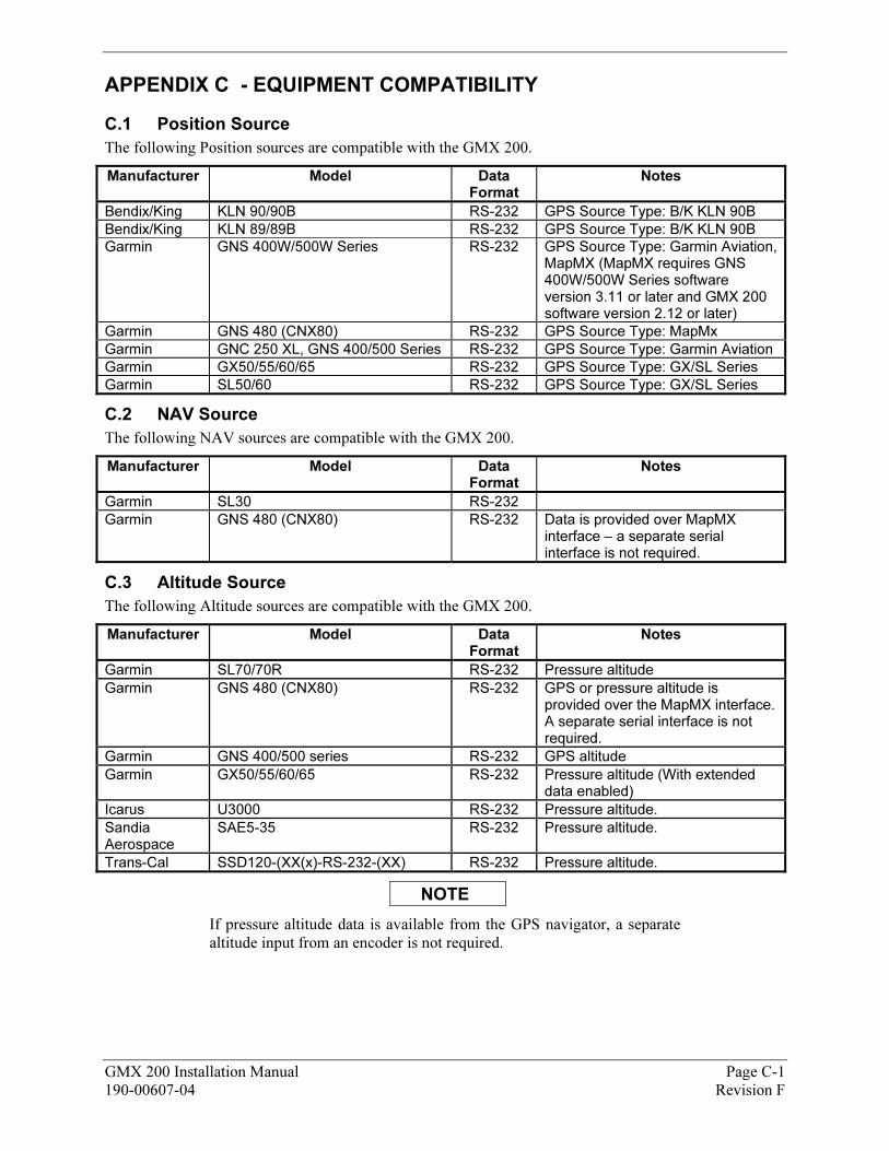
GMX 200 Installation Manual Page C-1 190-00607-04 Revision F
APPENDIX C 126B- EQUIPMENT COMPATIBILITY
C.1 Position Source
The following Position sources are compatible with the GMX 200.
Manufacturer Model Data Format
Notes
Bendix/King KLN 90/90B RS-232 GPS Source Type: B/K KLN 90B
Bendix/King KLN 89/89B RS-232 GPS Source Type: B/K KLN 90B
Garmin GNS 400W/500W Series RS-232 GPS Source Type: Garmin Aviation, MapMX (MapMX requires GNS 400W/500W Series software version 3.11 or later and GMX 200 software version 2.12 or later)
Garmin GNS 480 (CNX80) RS-232 GPS Source Type: MapMx
Garmin GNC 250 XL, GNS 400/500 Series RS-232 GPS Source Type: Garmin Aviation
Garmin GX50/55/60/65 RS-232 GPS Source Type: GX/SL Series
Garmin SL50/60 RS-232 GPS Source Type: GX/SL Series
C.2 NAV Source
The following NAV sources are compatible with the GMX 200.
Manufacturer Model Data Format
Notes
Garmin SL30 RS-232
Garmin GNS 480 (CNX80) RS-232 Data is provided over MapMX interface – a separate serial interface is not required.
C.3 Altitude Source
The following Altitude sources are compatible with the GMX 200.
Manufacturer Model Data Format
Notes
Garmin SL70/70R RS-232 Pressure altitude
Garmin GNS 480 (CNX80) RS-232 GPS or pressure altitude is provided over the MapMX interface. A separate serial interface is not required.
Garmin GNS 400/500 series RS-232 GPS altitude
Garmin GX50/55/60/65 RS-232 Pressure altitude (With extended data enabled)
Icarus U3000 RS-232 Pressure altitude.
Sandia Aerospace
SAE5-35 RS-232 Pressure altitude.
Trans-Cal SSD120-(XX(x)-RS-232-(XX) RS-232 Pressure altitude.
NOTE
If pressure altitude data is available from the GPS navigator, a separate altitude input from an encoder is not required.
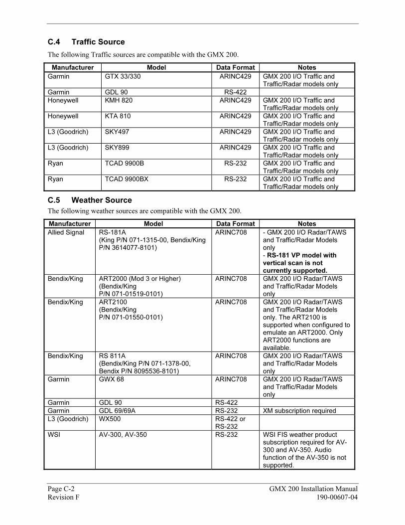
Page C-2 GMX 200 Installation Manual Revision F 190-00607-04
C.4 Traffic Source
The following Traffic sources are compatible with the GMX 200.
Manufacturer Model Data Format Notes
Garmin GTX 33/330 ARINC429 GMX 200 I/O Traffic and Traffic/Radar models only
Garmin GDL 90 RS-422
Honeywell KMH 820 ARINC429 GMX 200 I/O Traffic and Traffic/Radar models only
Honeywell KTA 810 ARINC429 GMX 200 I/O Traffic and Traffic/Radar models only
L3 (Goodrich) SKY497 ARINC429 GMX 200 I/O Traffic and Traffic/Radar models only
L3 (Goodrich) SKY899 ARINC429 GMX 200 I/O Traffic and Traffic/Radar models only
Ryan TCAD 9900B RS-232 GMX 200 I/O Traffic and Traffic/Radar models only
Ryan TCAD 9900BX RS-232 GMX 200 I/O Traffic and Traffic/Radar models only
C.5 Weather Source
The following weather sources are compatible with the GMX 200.
Manufacturer Model Data Format Notes
Allied Signal RS-181A (King P/N 071-1315-00, Bendix/King P/N 3614077-8101)
ARINC708 - GMX 200 I/O Radar/TAWS and Traffic/Radar Models only - RS-181 VP model with vertical scan is not currently supported.
Bendix/King ART2000 (Mod 3 or Higher) (Bendix/King P/N 071-01519-0101)
ARINC708 GMX 200 I/O Radar/TAWS and Traffic/Radar Models only
Bendix/King ART2100 (Bendix/King P/N 071-01550-0101)
ARINC708 GMX 200 I/O Radar/TAWS and Traffic/Radar Models only. The ART2100 is supported when configured to emulate an ART2000. Only ART2000 functions are available.
Bendix/King RS 811A (Bendix/King P/N 071-1378-00, Bendix P/N 8095536-8101)
ARINC708 GMX 200 I/O Radar/TAWS and Traffic/Radar Models only
Garmin GWX 68 ARINC708 GMX 200 I/O Radar/TAWS and Traffic/Radar Models only
Garmin GDL 90 RS-422
Garmin GDL 69/69A RS-232 XM subscription required
L3 (Goodrich) WX500 RS-422 or RS-232
WSI AV-300, AV-350 RS-232 WSI FIS weather product subscription required for AV-300 and AV-350. Audio function of the AV-350 is not supported.
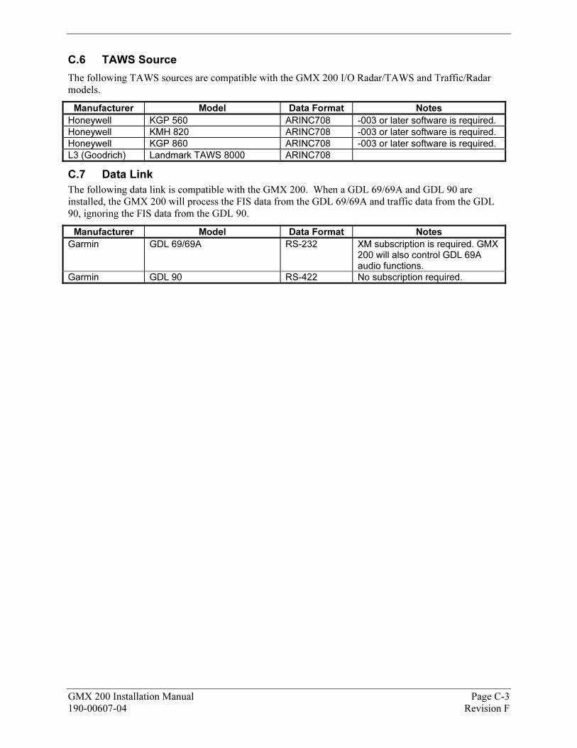
GMX 200 Installation Manual Page C-3 190-00607-04 Revision F
C.6 TAWS Source
The following TAWS sources are compatible with the GMX 200 I/O Radar/TAWS and Traffic/Radar models.
Manufacturer Model Data Format Notes
Honeywell KGP 560 ARINC708 -003 or later software is required.
Honeywell KMH 820 ARINC708 -003 or later software is required.
Honeywell KGP 860 ARINC708 -003 or later software is required.
L3 (Goodrich) Landmark TAWS 8000 ARINC708
C.7 Data Link
The following data link is compatible with the GMX 200. When a GDL 69/69A and GDL 90 are installed, the GMX 200 will process the FIS data from the GDL 69/69A and traffic data from the GDL 90, ignoring the FIS data from the GDL 90.
Manufacturer Model Data Format Notes
Garmin GDL 69/69A RS-232 XM subscription is required. GMX 200 will also control GDL 69A audio functions.
Garmin GDL 90 RS-422 No subscription required.

Page C-4 GMX 200 Installation Manual Revision F 190-00607-04
This Page Intentionally Left Blank
GMX 200 Installation Manual Page D-1 190-00607-04 Revision F
APPENDIX D 127B- ASSEMBLY AND INSTALLATION DRAWINGS
D.1 Introduction
This appendix contains assembly and installation drawings for the GMX 200.
D.2 Diagram List
� Figure D-1 – Connector Location
� Figure D-2 – Cockpit Panel Configuration for a Large Panel
� Figure D-3 – Cockpit Panel Configuration for a Small Panel
� Figure D-4 – Maximum Vertical Viewing Angle (Side View)
� Figure D-5 – Sample GNX 480 and GMX 200 Mounting with GNS 480
� Figure D-6 – GMX 200 Mounting Tube Assembly Dimensions
� Figure D-7 – GMX 200 and GMX 200 I/O Dimensions and Center of Gravity
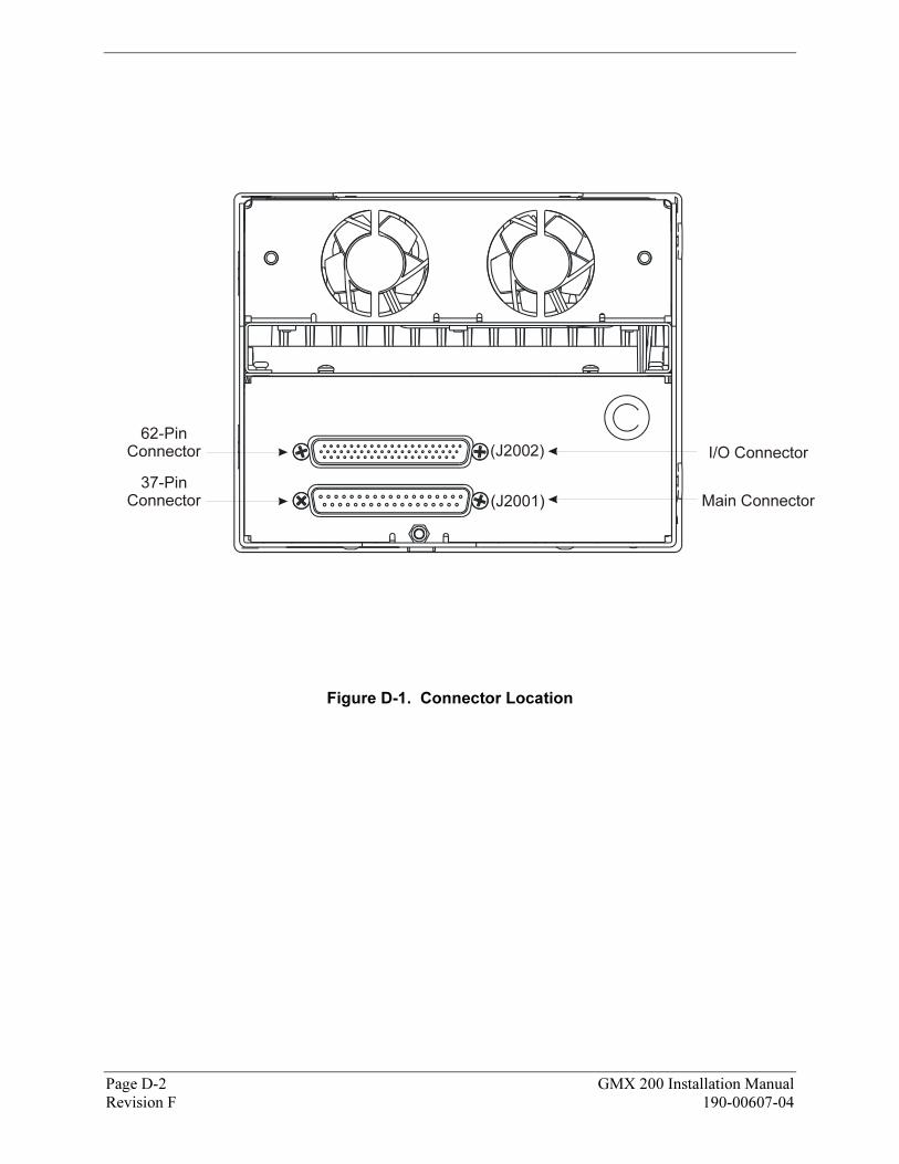
I/O Connector
62-PinConnector (J2002)
Main Connector37-Pin
Connector
Figure D-1. Connector Location
Page D-2 GMX 200 Installation Manual Revision F 190-00607-04
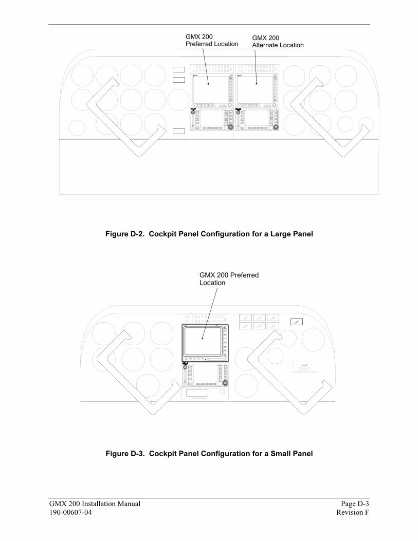
Figure D-2. Cockpit Panel Configuration for a Large Panel
MX20 MFD
Figure D-3. Cockpit Panel Configuration for a Small Panel
GMX 200 Installation Manual Page D-3 190-00607-04 Revision F
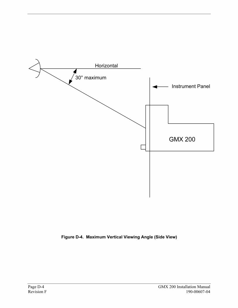
Horizontal
Instrument Panel
30° maximum
GMX 200
Figure D-4. Maximum Vertical Viewing Angle (Side View)
Page D-4 GMX 200 Installation Manual Revision F 190-00607-04
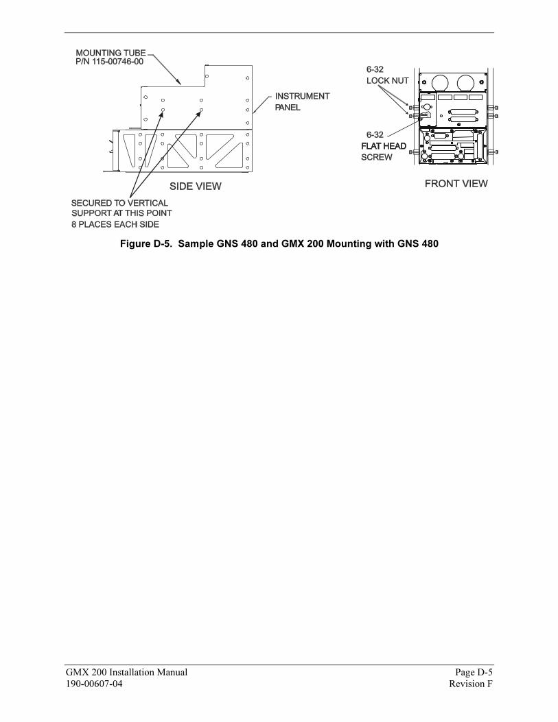
Figure D-5. Sample GNS 480 and GMX 200 Mounting with GNS 480
GMX 200 Installation Manual Page D-5 190-00607-04 Revision F
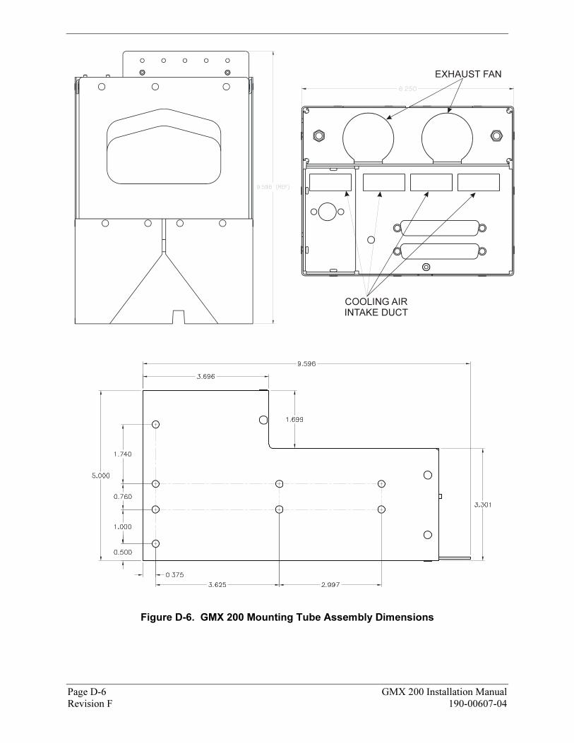
EXHAUST FAN
COOLING AIR
INTAKE DUCT
Figure D-6. GMX 200 Mounting Tube Assembly Dimensions
Page D-6 GMX 200 Installation Manual Revision F 190-00607-04
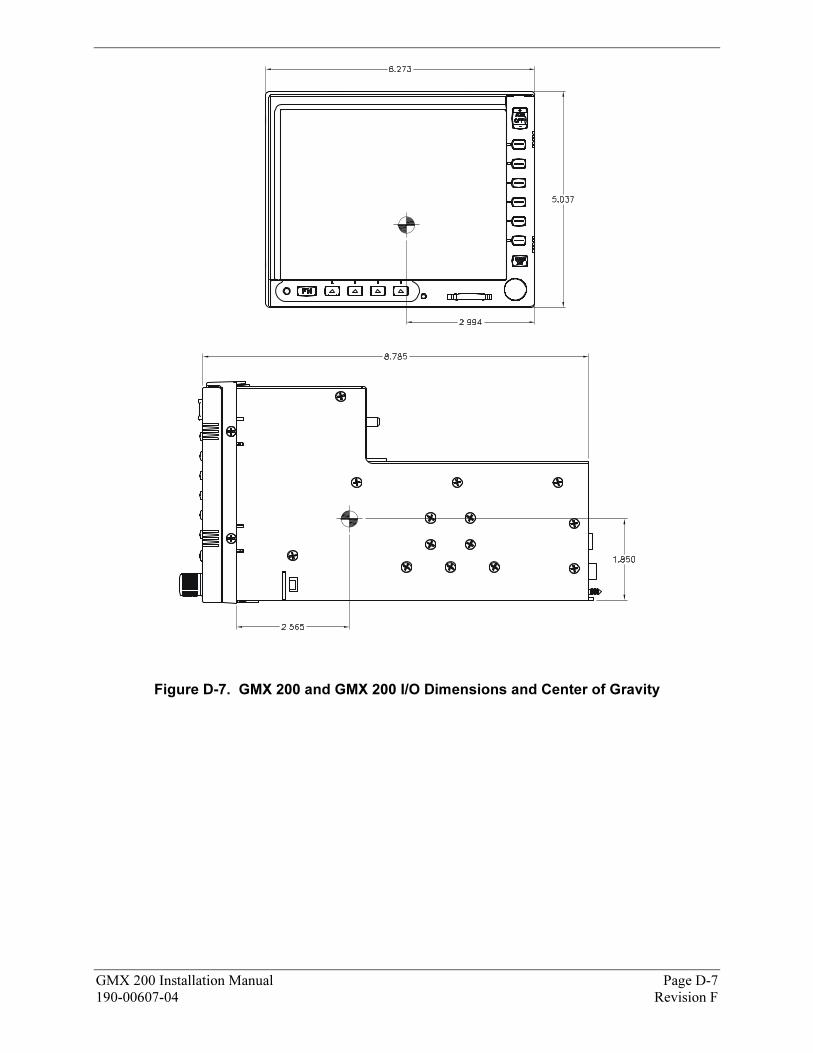
Figure D-7. GMX 200 and GMX 200 I/O Dimensions and Center of Gravity
GMX 200 Installation Manual Page D-7 190-00607-04 Revision F

Page D-8 GMX 200 Installation Manual Revision F 190-00607-04
This Page Intentionally Left Blank
GMX 200 Installation Manual Page E-1190-00607-04 Revision F
APPENDIX E 128B– INTERCONNECT DIAGRAMS
E.1 Introduction
This appendix contains interconnect diagrams for the GMX 200. The notes on each diagram contain configuration information for the GMX 200 and external sensors as appropriate.
E.2 Diagram List
� XFigure E-1. Power and Configuration Module
� XFigure E-2. GPS Position Source
� XFigure E-3. RS-232 Interfaces
� XFigure E-4. Stormscope
� XFigure E-5. FIS Data Link (excluding GDL90)
� XFigure E-6. GDL 90 Data Link (Includes Traffic)
� XFigure E-7. Traffic
� XFigure E-8. TAWS
� XFigure E-9. Weather Radar
� XFigure E-10. ARINC 453 Wiring for Multiple Radar Indicators

Page E-2 GMX 200 Installation Manual Revision F 190-00607-04
This Page Intentionally Left Blank
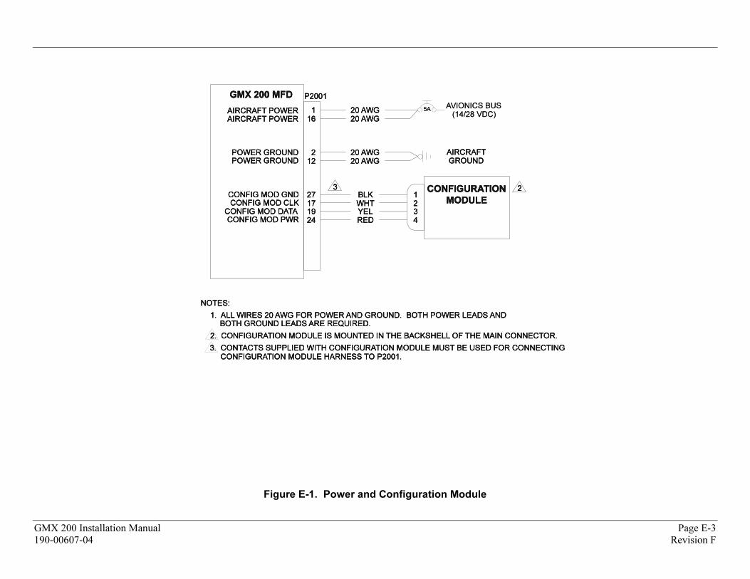
AIRCRAFT POWERAIRCRAFT POWERAIRCRAFT POWER
NOTES:NOTES:NOTES:
1. ALL WIRES 20 AWG FOR POWER AND GROUND. BOTH POWER LEADS AND1. ALL WIRES 20 AWG FOR POWER AND GROUND. BOTH POWER LEADS AND1. ALL WIRES 20 AWG FOR POWER AND GROUND. BOTH POWER LEADS AND
2. CONFIGURATION MODULE IS MOUNTED IN THE BACKSHELL OF THE MAIN CONNECTOR.2. CONFIGURATION MODULE IS MOUNTED IN THE BACKSHELL OF THE MAIN CONNECTOR.2. CONFIGURATION MODULE IS MOUNTED IN THE BACKSHELL OF THE MAIN CONNECTOR.
POWER GROUNDPOWER GROUNDPOWER GROUND
CONFIG MOD GNDCONFIG MOD GNDCONFIG MOD GND
P2001P2001P2001
BOTH GROUND LEADS ARE REQUIRED.BOTH GROUND LEADS ARE REQUIRED.BOTH GROUND LEADS ARE REQUIRED.
111161616
222121212
272727171717
AIRCRAFT POWERAIRCRAFT POWERAIRCRAFT POWER
POWER GROUNDPOWER GROUNDPOWER GROUND
CONFIG MOD CLKCONFIG MOD CLKCONFIG MOD CLKCONFIG MOD DATACONFIG MOD DATACONFIG MOD DATA 191919
242424CONFIG MOD PWRCONFIG MOD PWRCONFIG MOD PWR
20 AWG20 AWG20 AWG20 AWG20 AWG20 AWG
20 AWG20 AWG20 AWG20 AWG20 AWG20 AWG
BLKBLKBLKWHTWHTWHTYELYELYELREDREDRED
AIRCRAFTAIRCRAFTAIRCRAFTGROUNDGROUNDGROUND
AVIONICS BUSAVIONICS BUS(14/28 VDC)(14/28 VDC)
2 2 2
GMX 200 MFDGMX 200 MFDGMX 200 MFD
CONFIGURATION
MODULE
CONFIGURATION
MODULE
CONFIGURATION
MODULE111222333444
3. CONTACTS SUPPLIED WITH CONFIGURATION MODULE MUST BE USED FOR CONNECTING3. CONTACTS SUPPLIED WITH CONFIGURATION MODULE MUST BE USED FOR CONNECTING3. CONTACTS SUPPLIED WITH CONFIGURATION MODULE MUST BE USED FOR CONNECTINGCONFIGURATION MODULE HARNESS TO P2001.CONFIGURATION MODULE HARNESS TO P2001.CONFIGURATION MODULE HARNESS TO P2001.
333
5A5A
Figure E-1. Power and Configuration Module
GMX 200 Installation Manual Page E-3
190-00607-04 Revision F
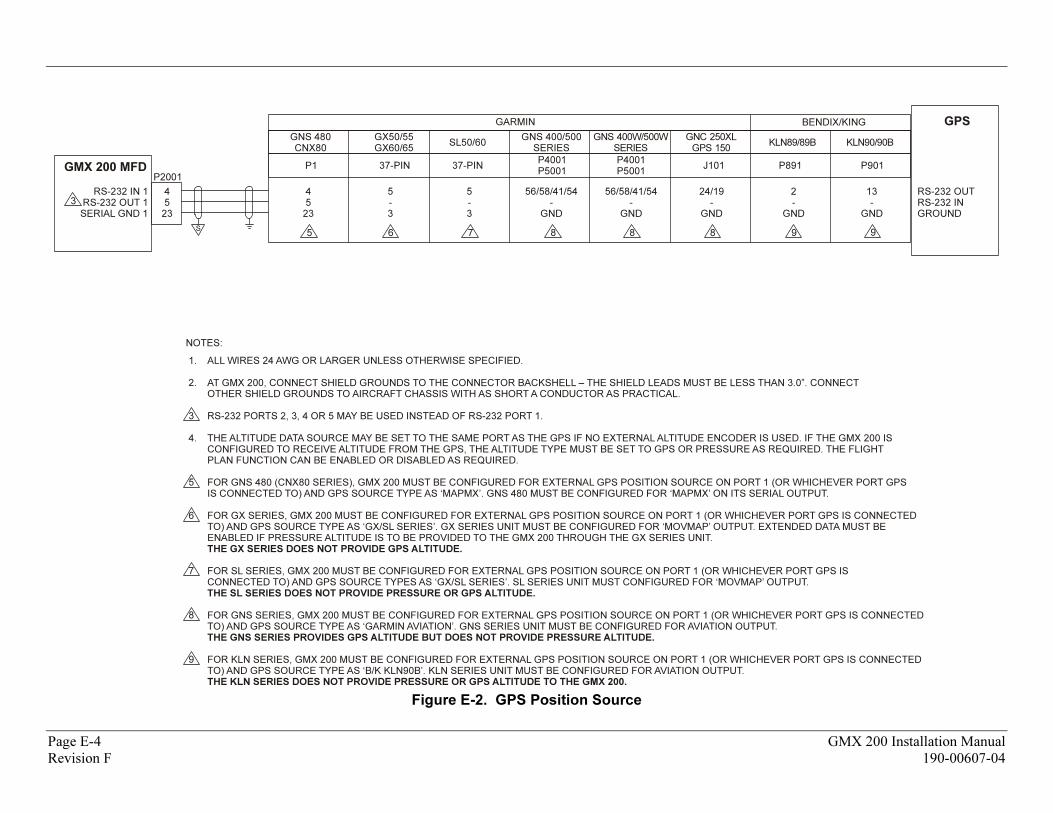
NOTES:
ALL WIRES 24 AWG OR LARGER UNLESS OTHERWISE SPECIFIED.
AT GMX 200, CONNECT SHIELD GROUNDS TO THE CONNECTOR BACKSHELL – THE SHIELD LEADS MUST BE LESS THAN 3.0”. CONNECTOTHER SHIELD GROUNDS TO AIRCRAFT CHASSIS WITH AS SHORT A CONDUCTOR AS PRACTICAL.
RS-232 PORTS 2, 3, 4 OR 5 MAY BE USED INSTEAD OF RS-232 PORT 1.
THE ALTITUDE DATA SOURCE MAY BE SET TO THE SAME PORT AS THE GPS IF NO EXTERNAL ALTITUDE ENCODER IS USED. IF THE GMX 200 ISCONFIGURED TO RECEIVE ALTITUDE FROM THE GPS, THE ALTITUDE TYPE MUST BE SET TO GPS OR PRESSURE AS REQUIRED. THE FLIGHTPLAN FUNCTION CAN BE ENABLED OR DISABLED AS REQUIRED.
FOR GNS 480 (CNX80 SERIES), GMX 200 MUST BE CONFIGURED FOR EXTERNAL GPS POSITION SOURCE ON PORT 1 (OR WHICHEVER PORT GPSIS CONNECTED TO) AND GPS SOURCE TYPE AS ‘MAPMX’. GNS 480 MUST BE CONFIGURED FOR ‘MAPMX’ ON ITS SERIAL OUTPUT.
FOR GX SERIES, GMX 200 MUST BE CONFIGURED FOR EXTERNAL GPS POSITION SOURCE ON PORT 1 (OR WHICHEVER PORT GPS IS CONNECTEDTO) AND GPS SOURCE TYPE AS ‘GX/SL SERIES’. GX SERIES UNIT MUST BE CONFIGURED FOR ‘MOVMAP’ OUTPUT. EXTENDED DATA MUST BEENABLED IF PRESSURE ALTITUDE IS TO BE PROVIDED TO THE GMX 200 THROUGH THE GX SERIES UNIT.
FOR SL SERIES, GMX 200 MUST BE CONFIGURED FOR EXTERNAL GPS POSITION SOURCE ON PORT 1 (OR WHICHEVER PORT GPS ISCONNECTED TO) AND GPS SOURCE TYPES AS ‘GX/SL SERIES’. SL SERIES UNIT MUST CONFIGURED FOR ‘MOVMAP’ OUTPUT.
FOR GNS SERIES, GMX 200 MUST BE CONFIGURED FOR EXTERNAL GPS POSITION SOURCE ON PORT 1 (OR WHICHEVER PORT GPS IS CONNECTEDTO) AND GPS SOURCE TYPE AS ‘GARMIN AVIATION’. GNS SERIES UNIT MUST BE CONFIGURED FOR AVIATION OUTPUT.
FOR KLN SERIES, GMX 200 MUST BE CONFIGURED FOR EXTERNAL GPS POSITION SOURCE ON PORT 1 (OR WHICHEVER PORT GPS IS CONNECTEDTO) AND GPS SOURCE TYPE AS ‘B/K KLN90B’. KLN SERIES UNIT MUST BE CONFIGURED FOR AVIATION OUTPUT.
THE GX SERIES DOES NOT PROVIDE GPS ALTITUDE.
THE SL SERIES DOES NOT PROVIDE PRESSURE OR GPS ALTITUDE.
THE GNS SERIES PROVIDES GPS ALTITUDE BUT DOES NOT PROVIDE PRESSURE ALTITUDE.
THE KLN SERIES DOES NOT PROVIDE PRESSURE OR GPS ALTITUDE TO THE GMX 200.
1.
2.
3
4.
5
6
7
8
9
45
23
GARMIN BENDIX/KING
GNS 480CNX80
GX50/55GX60/65
SL50/60GNS 400W/500W
SERIESGNS 400/500
SERIESGNC 250XL
GPS 150KLN89/89B KLN90/90B
P1 37-PIN 37-PINP4001P5001
P4001P5001
J101 P891 P901
S
P2001
RS-232 IN 1RS-232 OUT 1SERIAL GND 1
3
GMX 200 MFD
45
23
5 6 7 8 8 8 9 9
5-3
5-3
56/58/41/54-
GND
56/58/41/54-
GND
24/19-
GND
2-
GND
13-
GND
RS-232 OUTRS-232 INGROUND
GPS
Figure E-2. GPS Position Source
Page E-4 GMX 200 Installation Manual
Revision F 190-00607-04
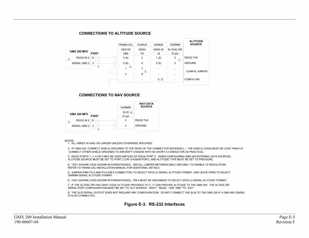
NOTES:1. ALL WIRES 24 AWG OR LARGER UNLESS OTHERWISE SPECIFIED.
2. AT GMX 200, CONNECT SHIELD GROUNDS TO THE REAR OF THE CONNECTOR BACKSHELL -- THE SHIELD LEADS MUST BE LESS THAN 3.0".
CONNECT OTHER SHIELD GROUNDS TO AIRCRAFT CHASSIS WITH AS SHORT A CONDUCTOR AS PRACTICAL.
3. RS232 PORTS 1, 3, 4 OR 5 MAY BE USED INSTEAD OF RS232 PORT 2. WHEN CONFIGURING GMX 200 EXTERNAL DATA SOURCES,
4. TXD1 SHOWN (TXD2 SHOWN IN PARENTHESES). INSTALL JUMPER BETWEEN DB9-2 AND DB9-1 TO ENABLE 10' RESOLUTION.
REFER TO TRANS-CAL INSTALLATION MANUAL FOR ADDITIONAL DETAILS.
5. JUMPER PINS P3-3 AND P3-8 (DB-9 CONNECTOR) TO SELECT APOLLO SERIAL ALTITUDE FORMAT, AND LEAVE OPEN TO SELECTGARMIN SERIAL ALTITUDE FORMAT.
6. TXD1 SHOWN (TXD2 SHOWN IN PARENTHESES). PIN 4 MUST BE GROUNDED TO SELECT APOLLO SERIAL ALTITUDE FORMAT.
7. IF THE SL70/SL70R HAS GRAY CODE ALTITUDE PROVIDED TO IT, IT CAN PROVIDE ALTITUDE TO THE GMX 200. THE SL70/SL70R
SERIAL PORT CONFIGURATION MUST BE SET TO "ALT SOURCE: GRAY", "BAUD: 1200" AND "TX: EXT".
8. THE SL30 SERIAL OUTPUT DOES NOT REQUIRE ANY CONFIGURATION. DO NOT CONNECT THE SL30 TO THE GMX 200 IF A GNS 480 (CNX80)
IS ALSO CONNECTED.
s
RS232 TxD
GROUND
21
3
RS232 IN 2
TRANS-CAL
SSD120
4 (9)
5 (8)
DB9
4
ICARUS
3000U
2
5
P3
SANDIA
SAE5-35
1 (2)
5 (5)
J5
3
3
8
1
25
4
-
-
- - CONFIG PIN6
SL70/SL70R
5
3
37-pin
-
-
-
RS232 TxD
GROUND
21
3
SL30
5
3
37-pin
8
3
GMX 200 MFD
SERIAL GND 2
GARMIN
7
CONFIG JUMPER
P2001
P2001
SERIAL GND 2
RS232 IN 2
GMX 200 MFD
s
GARMIN
NAV DATA
SOURCE
ALTITUDE
SOURCE
ALTITUDE SOURCE MUST BE SET TO PORT 2 (OR CHOSEN PORT), AND ALTITUDE TYPE MUST BE SET TO PRESSURE.
CONNECTIONS TO NAV SOURCE
CONNECTIONS TO ALTITUDE SOURCE
Figure E-3. RS-232 Interfaces
GMX 200 Installation Manual Page E-5
190-00607-04 Revision F
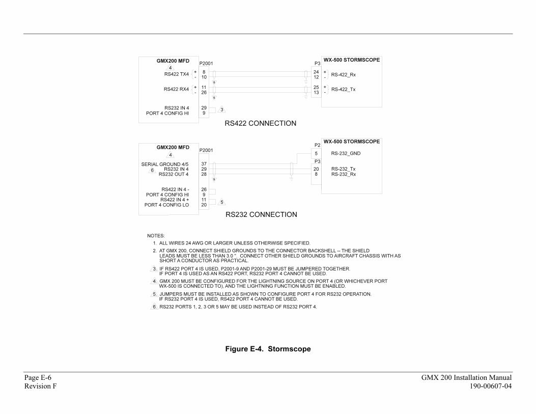
2937SERIAL GROUND 4/5
26
2011
RS-232_GND
RS-232_Tx
NOTES:
1. ALL WIRES 24 AWG OR LARGER UNLESS OTHERWISE SPECIFIED.
2. AT GMX 200, CONNECT SHIELD GROUNDS TO THE CONNECTOR BACKSHELL -- THE SHIELD LEADS MUST BE LESS THAN 3.0 ". CONNECT OTHER SHIELD GROUNDS TO AIRCRAFT CHASSIS WITH AS SHORT A CONDUCTOR AS PRACTICAL.
3. IF RS422 PORT 4 IS USED, P2001-9 AND P2001-29 MUST BE JUMPERED TOGETHER.
4. GMX 200 MUST BE CONFIGURED FOR THE LIGHTNING SOURCE ON PORT 4 (OR WHICHEVER PORT
IF PORT 4 IS USED AS AN RS422 PORT, RS232 PORT 4 CANNOT BE USED.
WX-500 IS CONNECTED TO), AND THE LIGHTNING FUNCTION MUST BE ENABLED.
P2001GMX200 MFD
WX-500 STORMSCOPE
20
5
8
P2
5
6
RS422 IN 4 +PORT 4 CONFIG LO
108RS422 TX4
+-
2611+
-
929
+-
RS-422_Rx
+-
RS-422_TxRS422 RX4
P2001GMX200 MFD WX-500 STORMSCOPE
1224
1325
P3
3
4
RS232 IN 4PORT 4 CONFIG HI
RS422 CONNECTION
RS232 CONNECTION
RS232 IN 4RS232 OUT 4 28
9RS422 IN 4 -
PORT 4 CONFIG HI
4
RS-232_Rx
P3
5. JUMPERS MUST BE INSTALLED AS SHOWN TO CONFIGURE PORT 4 FOR RS232 OPERATION.IF RS232 PORT 4 IS USED, RS422 PORT 4 CANNOT BE USED.
6. RS232 PORTS 1, 2, 3 OR 5 MAY BE USED INSTEAD OF RS232 PORT 4.
s
s
s
Figure E-4. Stormscope
Page E-6 GMX 200 Installation Manual
Revision F 190-00607-04
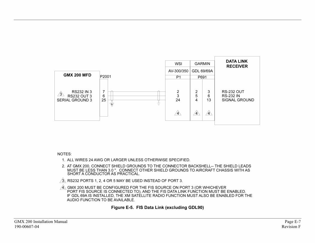
GARMIN
GDL 69/69A
P691
7RS232 IN 3
256
254
NOTES:
1. ALL WIRES 24 AWG OR LARGER UNLESS OTHERWISE SPECIFIED.
2. AT GMX 200, CONNECT SHIELD GROUNDS TO THE CONNECTOR BACKSHELL-- THE SHIELD LEADS MUST BE LESS THAN 3.0 ". CONNECT OTHER SHIELD GROUNDS TO AIRCRAFT CHASSIS WITH AS SHORT A CONDUCTOR AS PRACTICAL.
3. RS232 PORTS 1, 2, 4 OR 5 MAY BE USED INSTEAD OF PORT 3.
4. GMX 200 MUST BE CONFIGURED FOR THE FIS SOURCE ON PORT 3 (OR WHICHEVER
RS232 OUT 3SERIAL GROUND 3
PORT FIS SOURCE IS CONNECTED TO), AND THE FIS DATA LINK FUNCTION MUST BE ENABLED.
P2001GMX 200 MFD
DATA LINK
RECEIVER
RS-232 OUTRS-232 INSIGNAL GROUND
3613
4 4
3
IF GDL 69A IS INSTALLED, THE XM SATELLITE RADIO FUNCTION MUST ALSO BE ENABLED FOR THEAUDIO FUNCTION TO BE AVAILABLE.
s
WSI
AV-300/350
P1
2
24
4
Figure E-5. FIS Data Link (excluding GDL90)
GMX 200 Installation Manual Page E-7
190-00607-04 Revision F
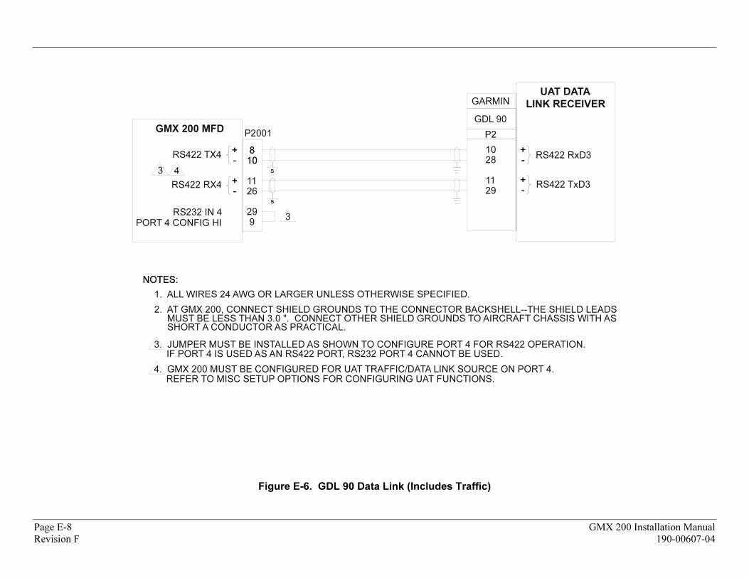
101088
RS422 TX4++--
2611++
--
929
++--
RS422 RxD3
++--
RS422 TxD3
NOTES:NOTES:
1. ALL WIRES 24 AWG OR LARGER UNLESS OTHERWISE SPECIFIED.
2. AT GMX 200, CONNECT SHIELD GROUNDS TO THE CONNECTOR BACKSHELL--THE SHIELD LEADS MUST BE LESS THAN 3.0 ". CONNECT OTHER SHIELD GROUNDS TO AIRCRAFT CHASSIS WITH AS SHORT A CONDUCTOR AS PRACTICAL.
3. JUMPER MUST BE INSTALLED AS SHOWN TO CONFIGURE PORT 4 FOR RS422 OPERATION.
4. GMX 200 MUST BE CONFIGURED FOR UAT TRAFFIC/DATA LINK SOURCE ON PORT 4.
RS422 RX4
IF PORT 4 IS USED AS AN RS422 PORT, RS232 PORT 4 CANNOT BE USED.
REFER TO MISC SETUP OPTIONS FOR CONFIGURING UAT FUNCTIONS.
P2001GMX 200 MFD
UAT DATA
LINK RECEIVER
2810
2911
3
3 4
RS232 IN 4
PORT 4 CONFIG HI
s
s
GARMIN
GDL 90
P2
Figure E-6. GDL 90 Data Link (Includes Traffic)
Page E-8 GMX 200 Installation Manual
Revision F 190-00607-04
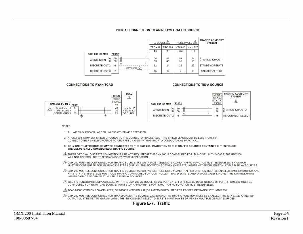
TYPICAL CONNECTION TO ARINC 429 TRAFFIC SOURCE
S
GMX 200 I/O MFD
ARINC 429 IN
DISCRETE OUT 2
DISCRETE OUT 3
AB
3433
82
85
P2002
TRC 497 TRC 899
P1 P1
KTA 810 KMH 820
J10 J10
5958
6
7
4243
21
19
5455
23
2
5455
23
2
L3 COMM 5 HONEYWELL 6TRAFFIC ADVISORY
SYSTEM
ARINC 429 OUTAB
STANDBY/OPERATE
FUNCTIONAL TEST
(OPTIONAL) 4
GMX 200 I/O MFD
RS-232 OUT 3RS-232 IN 3
SERIAL GND 3
67
25
P2001
RYAN9900B
9900BXP1
222021
RS-232 RXRS-232 TXGROUND
TCAD
8
7
CONNECTIONS TO RYAN TCAD
S
S
GMX 200 I/O MFD
ARINC 429 IN
DISCRETE OUT 2
AB
P2002
5958
6
GARMINGTX 33GTX 330P3301
3028
46
TRAFFIC ADVISORY
SYSTEM
TIS CONNECT SELECT
AB
CONNECTIONS TO TIS-A SOURCE
ARINC 429 OUT 2
9
NOTES
ALL WIRES 24 AWG OR LARGER UNLESS OTHERWISE SPECIFIED.
AT GMX 200, CONNECT SHIELD GROUNDS TO THE CONNECTOR BACKSHELL – THE SHIELD LEADS MUST BE LESS THAN 3.0”.CONNECT OTHER SHIELD GROUNDS TO AIRCRAFT CHASSIS WITH AS SHORT A CONDUCTOR AS PRACTICAL.
THESE OPTIONAL DISCRETE CONNECTIONS ARE NOT REQUIRED IF THE GMX 200 IS CONFIGURED FOR ‘TAS+DISP’. IN THIS CASE, THE GMX 200WILL NOT CONTROL THE TRAFFIC ADVISORY SYSTEM OPERATION.
GMX 200 MUST BE CONFIGURED FOR TRAFFIC SOURCE: TAS OR TAS+DISP (SEE NOTE 4), AND TRAFFIC FUNCTION MUST BE ENABLED. SKYWATCHMUST BE CONFIGURED FOR AN ARINC 735 TYPE 1 DISPLAY. THE SKYWATCH SOFTKEY (DISCRETE) INPUTS MAY BE DRIVEN BY MULTIPLE DISPLAY SOURCES.
GMX 200 MUST BE CONFIGURED FOR TRAFFIC SOURCE: TAS OR TAS+DISP (SEE NOTE 4), AND TRAFFIC FUNCTION MUST BE ENABLED. KMH 880 KMH 820) ANDKTA 870 (KTA 810) SYSTEMS MUST HAVE TRAFFIC CONFIGURED FOR ‘CONTROLLER TYPE: DISCRETE’ AND ‘DISPLAY VALID: IGNORE’. THE KTA 810/KMH 820 INPUTS CANNOT BE DRIVEN BY MULTIPLE DISPLAY SOURCES.
TRAFFIC FUNCTION IS ONLY AVAILABLE WITH THE GMX 200 I/O MODEL. RS-232 PORTS 1, 2, 4 OR 5 MAY BE USED INSTEAD OF PORT 3. GMX 200 MUST BECONFIGURED FOR RYAN TCAD SOURCE: PORT 3 (OR APPROPRIATE PORT) AND TRAFFIC FUNCTION MUST BE ENABLED.
TCAD 9900B VERSION 1.08 (OR LATER) OR 9900BX VERSION 1.11 (OR LATER) IS REQUIRED FOR PROPER OPERATION WITH GMX 200.
GMX 200 MUST BE CONFIGURED FOR TRANSPONDER TIS SOURCE: GTX 330 AND THE TRAFFIC FUNCTION MUST BE ENABLED. THE GTX 33/330 ARINC 429OUTPUT MUST BE SET TO ‘GARMIN W/TIS’. THE ‘TIS CONNECT SELECT’ DISCRETE INPUT MAY BE DRIVEN BY MULTIPLE DISPLAY SOURCES.
ONLY ONE TRAFFIC SOURCE MAY BE CONNECTED TO THE GMX 200. IN ADDITION TO THE TRAFFIC SOURCES CONTAINED IN THIS FIGURE,
THE GDL 90 IS ALSO CONSIDERED A TRAFFIC SOURCE.
1.
2.
4
5
6
7
8
9
3.
Figure E-7. Traffic
GMX 200 Installation Manual Page E-9
190-00607-04 Revision F
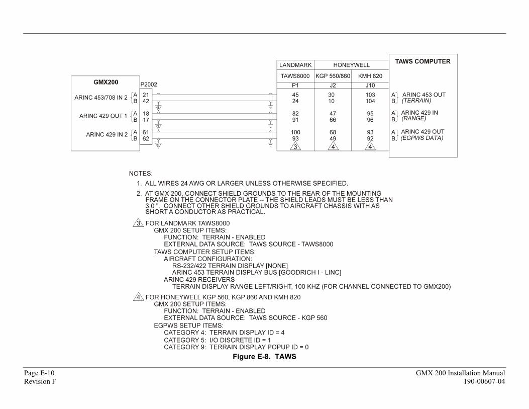
LANDMARK
TAWS8000
P1
HONEYWELL
KGP 560/860
J2
KMH 820
J10
42
21ARINC 453/708 IN 2
A
B
17
18A
B
62
61A
B
A
B
ARINC 453 OUT
A
B
ARINC 429 IN
A
B
ARINC 429 OUT
30
10
66
68
49
103
104
95
96
93
92
45
24
82
91
100
93
NOTES:
1. ALL WIRES 24 AWG OR LARGER UNLESS OTHERWISE SPECIFIED.
2. AT GMX 200, CONNECT SHIELD GROUNDS TO THE REAR OF THE MOUNTING FRAME ON THE CONNECTOR PLATE -- THE SHIELD LEADS MUST BE LESS THAN 3.0 ". CONNECT OTHER SHIELD GROUNDS TO AIRCRAFT CHASSIS WITH AS SHORT A CONDUCTOR AS PRACTICAL.
3. FOR LANDMARK TAWS8000
4. FOR HONEYWELL KGP 560, KGP 860 AND KMH 820
ARINC 429 OUT 1
ARINC 429 IN 2
GMX 200 SETUP ITEMS:FUNCTION: TERRAIN - ENABLEDEXTERNAL DATA SOURCE: TAWS SOURCE - TAWS8000
TAWS COMPUTER SETUP ITEMS:AIRCRAFT CONFIGURATION:
RS-232/422 TERRAIN DISPLAY [NONE]ARINC 453 TERRAIN DISPLAY BUS [GOODRICH I - LINC]
ARINC 429 RECEIVERSTERRAIN DISPLAY RANGE LEFT/RIGHT, 100 KHZ (FOR CHANNEL CONNECTED TO GMX200)
GMX 200 SETUP ITEMS:FUNCTION: TERRAIN - ENABLEDEXTERNAL DATA SOURCE: TAWS SOURCE - KGP 560
EGPWS SETUP ITEMS:CATEGORY 4: TERRAIN DISPLAY ID = 4
CATEGORY 5: I/O DISCRETE ID = 1CATEGORY 9: TERRAIN DISPLAY POPUP ID = 0
P2002GMX200
TAWS COMPUTER
s
s
s 3 4 4
Figure E-8. TAWS
Page E-10 GMX 200 Installation Manual
Revision F 190-00607-04
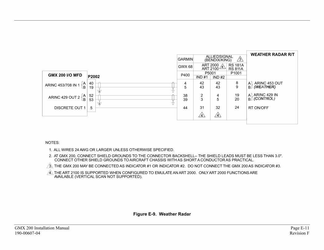
3
4 4
4
Figure E-9. Weather Radar
GMX 200 Installation Manual Page E-11
190-00607-04 Revision F

This Page Intentionally Left Blank
Page E-12 GMX 200 Installation Manual
Revision F 190-00607-04
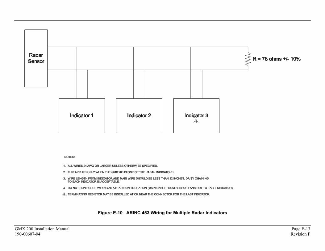
5
Figure E-10. ARINC 453 Wiring for Multiple Radar Indicators
GMX 200 Installation Manual Page E-13
190-00607-04 Revision F

Revision F 190-00607-04
Page E-14 GMX 200 Installation Manual
This Page Intentionally Left Blank