Embed Size (px)
Citation preview
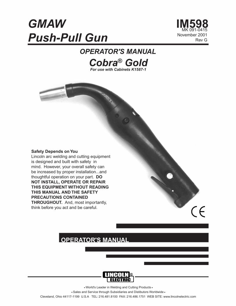
Cobra® GoldFor use with Cabinets K1587-1
MK 091-0415November 2001
Rev G
OPERATOR'S MANUAL
GMAWPush-Pull Gun
Safety Depends on YouLincoln arc welding and cutting equipment is designed and built with safety in mind. However, your overall safety can be increased by proper installation...and thoughtful operation on your part. DO NOT INSTALL, OPERATE OR REPAIR THIS EQUIPMENT WITHOUT READING THIS MANUAL AND THE SAFETY PRECAUTIONS CONTAINED THROUGHOUT. And, most importantly, think before you act and be careful.
Cleveland, Ohio 44117-1199 U.S.A TEL: 216.481.8100 FAX: 216.486.1751 WEB SITE: www.lincolnelectric.com
IM598
OPERATOR'S MANUAL
• World's Leader in Welding and Cutting Products •
• Sales and Service through Subsidiaries and Distibutors Worldwide •


Printed in the U.S.A.

Cobra Gold Owner's Manual - Page 1
Table of Contents
Safety Guidelines ..................................................................................................i-iv
Installation.................................................................................................. Section A
Technical Specifications .........................................................................................3Support Equipment Required.................................................................................3Coolant Recommendations....................................................................................3Torch Lead Connections ........................................................................................4
Operation.................................................................................................... Section B
General ..................................................................................................................4Controls and Settings.............................................................................................5Drive Roll and Idler Rolls........................................................................................5Drive Roll Installation/Removal ..............................................................................6Idler Roll Installation and Removal.........................................................................6
Accessories ............................................................................................... Section C
Contact Tips ...........................................................................................................7Torch Liners............................................................................................................7Gas Cups ...............................................................................................................7Optional Kits...........................................................................................................8Accessories............................................................................................................9
Maintenance............................................................................................... Section D
Periodic Maintenance...........................................................................................10Recommended Spare Parts List ..........................................................................11
Troubleshooting......................................................................................... Section E
Troubleshooting Guide .........................................................................................13Testing The Torch .................................................................................................13
Appendices .................................................................................................Section F
Diagrams / Parts List ............................................................................................17Mechanical ...........................................................................................................18Electrical...............................................................................................................22
MK Warranty Repair Centers
Safety Warnings
Waranty

Cobra Gold Owner's Manual - Page 2
This Page left intentionally blank

Cobra Gold Owner's Manual - Page 3
Section A Installation
Technical Specifications
Wire Capacity
.023inch - .045inch (0.8mm - 1.2mm) solid and hard wire
.030inch - 1/16inch (0.8mm - 1.6mm) aluminum and cored wire
Wire Speed
800 IPM (20mpm) Max. at rated feeder Input Voltage (120VAC / 42VAC)
Duty Cycle
Air Cooled Torches (K1589 series) ...................................................................... 200 amps @50%
Water Cooled Torches (K1590 series) ...................................................................... 250 amps @50%
Water Cooled Torches with Optional Heavy Duty Finned Gas Cup...................... 300 amps @50%
All ratings are at 25 volts max. using Argon Gas
Shipping Weight (approximate)
Air Cooled
15ft. (4.5m) ....................................... 13 lbs. (5.9 Kg)25ft. (7.6m) ....................................... 18 lbs. (8.2 Kg)50ft. (15.2m) ..................................... 33 lbs. (14.96 Kg)
Water Cooled
15ft. (4.5m) ....................................... 14 lbs. (6.35 Kg)25ft. (7.6m) ....................................... 20 lbs. (9.07 Kg)50ft. (15.2m) ..................................... 35 lbs. (15.88 Kg)
Support Equipment Required• PowerWave or Invertec Power Source with 42VAC Connector output.
• Regulated gas supply and hoses.
• Properly sized power leads from power source to wire feeder and ground.
• Water source and hose capable of providing a minimum of 1 quart (.95 liter) / min. at 35 p.s.i. when using water cooled torches.
Coolant RecommendationsUse a name-brand additive, which does not contain reactive sulphur or chlorine and does not react with copper, brass or aluminum.
Use 3 Quarts (2.85 Liters) Distilled water.
Use 1 Quart (.95 Liters) ethylene glycol.
Use 1 tsp (5 ml) liquid glycerin
The Coolant rate should be 1 quart (.95 liter) / minute at 35 p.s.i.

Cobra Gold Owner's Manual - Page 4
Torch Lead Connections
Power Cable
IMPORTANT - PLEASE NOTE——————————————————————————————
Water cooled torches use a #4 AWG power cable inside a flexible hose. Because of the size of cable used,
these torches MUST be WATER COOLED. ——————————————————————————————
The torch fitting is screwed into the back of the torch block using a conductive sealant. Air cooled torches, on the other hand, use a #2 AWG power cable, which is secured to the torch in the same manner. The power cable fitting on the other end connects to the power block inside the Cobramatic feeder.
Conduit
The Cobra Gooseneck comes standard with a Teflon-lined conduit. The torch end is secured with a setscrew accessible through a hole in the handle. The other end is connected to the wire feeder. Spiral steel conduits are available when using hard and cored wires.
Gas Hose
The gas hose is pushed on to the inlet tube of the front body, and then secured with a plastic cable tie. The gas inlet tube is located in the middle of the torch block, when viewed from the rear.
Water Hose
The water hose is pushed on to the inlet tube of the front body. The other end goes to the return side of the water recirculator. The Water tube is located in the upper right of the torch block, when viewed from the rear. Air cooled torches do not have a Water Hose.
Electric Cable
A seven conductor control cable is used on the Gooseneck Torch. The torch end of the control cable is secured to the back of the torch with a cable clamp and the wires are joined to the motor, pot, and micro switch through two connectors. The cabinet end has a 7 pin “W” clocked Amphenol connector. See the schematic in the appendix for wiring information.
Section B Operation
GeneralThe patented Cobra Gooseneck Torch maintains a constant, steady, uniform wire feed speed, regardless of curved or looped wire conduit. The constant push exerted by the slave motor in the cabinet, combined with the pull of the torch motor, causes the wire to literally float friction-free through the wire conduit. The 24VDC torch motor is controlled by a three (3)-turn potentiometer in the torch handle.
Section A (Cont.)

Cobra Gold Owner's Manual - Page 5
Controls and Settings
Potentiometer
The potentiometer is located on the left hand side of the torch and provides three (3) turns of adjustment. A special pot nut and O-Ring provides drag on the knob and also secures the pot to the handle.
Trigger, Gas Valve and Micro Switch
The torch trigger is designed so that when it is partially depressed, gas flow starts via the valve located in the torch body, prior to ignition of the arc. When the trigger is partially released after welding (extinguishing the arc), gas flow continues until the trigger is fully released; built-in pre and post gas flow.
The micro switch is wired “Normally Open” and secured to the torch block with two (2) screws. An insulator between the torch block and micro switch prevents accidental shorting of the switch leads. The trigger pin reaches through the handle and activates the micro switch just before the trigger bottoms out on the handle.
Drive Roll and Idler Rolls
General
The Gooseneck torch comes standard with knurled drive rolls, which will handle wire diameters from .023 through 1/16 inch. Optional insulated V-groove drive rolls are also available for improved feeding of aluminum wire (see Optional Kits).
Drive roll tension is accomplished by means of a pressure-adjusting screw located on the left hand side of the torch. Proper tension is achieved when wire does not slip if a small amount of pressure is added to the wire as it exits the tip.
----------- IMPORTANT -----------
NOTE: Over-tightening of the drive rolls will cause excessive knurling and/or deformation of the wire. When the complete system is setup properly,
feeding wire out of the end of the torch and letting fall on the ground should form a large uniform circle. If it forms a spiral or spring then there is too
much tension in the system, please refer to the Cabinet Owners Manual for adjustment to the tension setting.
INCORRECT DRIVE ROLL TENSION IS THE NUMBER ONE CAUSE OF POOR WIRE FEED PERFORMANCE
---------------------------------------------
Section B (Cont.)

Cobra Gold Owner's Manual - Page 6
Drive Roll Installation/RemovalNoteNeither of the handles needs to be removed to access the Drive or Idler Rolls.
1. Using a 5/32" hex wrench, loosen the Idler Roll tension screw. This will relieve the pressure against the drive roll.
2. Align the Drive Roll Removal Tool (P/N 931-0100) over the flats of the drive roll. Hold the torch with one hand or on a table top, with the other hand give the Removal Tool a quick snap-turn in the CLOCKWISE DIRECTION.
Figure 13. Once the drive roll is loose, continue to spin drive roll in the clockwise
direction to remove the drive roll from the torch.
4. Install a new drive roll on the left-hand threaded shaft. The drive roll will self-tighten when it is feeding wire.
Idler Roll Installation and Removal1. Using a slot type screwdriver, loosen idler screw, taking care not to lose
lock washer under idler roll.
2. Insert new idler roll and lock washer onto screw, insuring that idler groove is toward top and lock washer is beneath.
Figure 23. Tighten.
4. Using a 5/32" hex wrench, turn the Idler Roll tension screw into the gearbox housing to adjust the pressure against the drive roll.
NOTE: Lock washer must be under idler roll or it will not turn freely.
LOCKWASHER
SCREW
SPRING
GROOVETOWARDS
TOP
IDLERARM
IDLERROLL
Section B (Cont.)

Cobra Gold Owner's Manual - Page 7
Section C Consumables
Contact TipsSpray Arc
Short Arc
*Standard - Furnished with torch
Standard CupHeavy Duty Finned Cup
ediuGrotceleSpiTtcatnoCeziSeriW eziSeriW eziSeriW eziSeriW eziSeriW **.D.IpiT **.D.IpiT **.D.IpiT **.D.IpiT **.D.IpiT crA crA crA crA crA htgneLpiT htgneLpiT htgneLpiT htgneLpiT htgneLpiT N/PEL N/PEL N/PEL N/PEL N/PEL N/PKM N/PKM N/PKM N/PKM N/PKM
)mm6.0(”320.)mm8.0(”030. yarpS )mm83(”2/1-1 -- 7500-126
)mm6.0(”320.)mm8.0(”030. trohS )mm44(”4/3-1 --- 8230-126
)mm8.0(”030.)mm9.0(”630. yarpS )mm83(”2/1-1 -- 5230-126
)mm8.0(”030.)mm9.0(”630. trohS )mm44(”4/3-1 -- 6230-126
)mm8.0("030.ro
)mm9.0("530.
)mm0.1(”040. yarpS )mm83(”2/1-1 92-87932S 6700-126)mm8.0("030.ro
)mm9.0("530. )mm0.1(”040. trohS )mm44(”4/3-1 -- 7700-126
)mm9.0(”530.)mm1.1(”440. yarpS )mm83(”2/1-1 1-87932S 1000-126
)mm9.0(”530.)mm1.1(”440. trohS )mm44(”4/3-1 -- 2000-126
)mm2.1(”540. )mm3.1(”350. yarpS )mm83(”2/1-1 -- 7230-126
)mm2.1("540.ro
)mm3.1(”250.
)mm5.1(”060. yarpS )mm83(”2/1-1 *2-87932S 3000-126)mm2.1("540.ro
)mm3.1(”250. )mm5.1(”060. trohS )mm44(”4/3-1 -- 6820-126
)mm6.1(”61/1 )mm9.1(”570. yarpS )mm83(”2/1-1 3-87932S 5700-126
)mm6.1(”61/1)mm1.2(”580. yarpS )mm83(”2/1-1 -- 3510-126
)mm6.1(”61/1)mm1.2(”580. trohS )mm44(”4/3-1 -- 4510-126
spuCsaGdradnatS spuCsaGytuD-yvaeHeziS eziS eziS eziS eziS .D.I .D.I .D.I .D.I .D.I N/P.E.L N/P.E.L N/P.E.L N/P.E.L N/P.E.L N/PKM N/PKM N/PKM N/PKM N/PKM eziS eziS eziS eziS eziS .D.I .D.I .D.I .D.I .D.I N/P.E.L N/P.E.L N/P.E.L N/P.E.L N/P.E.L N/PKM N/PKM N/PKM N/PKM N/PKM
55555 ”4/1)mm4.6(
-- 9700-126
66666 ”8/3)mm5.9(
-- 7310-100
8*8*8*8*8* ”2/1)mm7.21(
4-87932S 8310-100 88888 ”2/1)mm7.21(
02-87932S 6630-126
0101010101 ”8/5)mm8.51(
9310-100 0101010101 ”8/5)mm8.51(
7630-126
* Standard - Furnished with torch. ** All tips stamped with tip I.D.
NOTE: As a rule of thumb, use the smaller I.D. tip for steel, stainless steel and the 5000 series aluminum. Softer alloys such as the 1000 and 4000 series aluminum require more clearance and, therefore, use a larger I.D. tip.
Gas Cups

Cobra Gold Owner's Manual - Page 8
Section C (Cont.)
*Standard - Furnished with torch
Optional Kits
Insulated Drive Roll Kits
Insulated Groove Drive Roll Kits are used to prevent preheating of the aluminum wire which may soften it and clog the liner. This picking up of current at the drive rolls rather than at the contact tip is usually not a problem unless using too large of a contact tip or excessively oxidized aluminum wire.
Insulated Groove Drive Roll Kit for .030" (0.8mm) dia. wire ....... 005-0640Includes insulated drive roll P/N 511-0150 and idler roll assembly P/N 003-1870.
Insulated Groove Drive Roll Kit for .035" (0.9mm) dia. wire ....... 005-0641Includes insulated drive roll P/N 511-0151 and idler roll assembly P/N 003-1870.
Insulated Groove Drive Roll Kit for .040" (1.0mm) dia. wire ....... 005-0642Includes insulated drive roll P/N 511-0152 and idler roll assembly P/N 003-1870.
Insulated Groove Drive Roll Kit for .045" (1.2mm) dia. wire ....... 005-0643Includes insulated drive roll P/N 511-0153 and idler roll assembly P/N 003-1870.
Insulated Groove Drive Roll Kit for .062" (1.6mm) dia. wire ....... 005-0644Includes insulated drive roll P/N 511-0154 and idler roll assembly P/N 003-1870.
Tip Extender
Tip Extender ..............................................................Lincoln P/N S23978-27...........................................................................................................621-0017A tip extender is used if the torch cup or tip threads have been damaged or to prevent damage. Longer liners are required when using a tip extender.
Long Teflon Liner ..................................................................... 615-0058Long Spiral Steel Liner ............................................................ 615-0057
Note: If more than one tip extender is used, the liner must be purchased in bulk and cut to size.
sreniLhcroTkcenesooG
.oNtraP .oNtraP .oNtraP .oNtraP .oNtraP lairetaMreniL lairetaMreniL lairetaMreniL lairetaMreniL lairetaMreniL htgneL htgneL htgneL htgneL htgneL epyTeriW epyTeriW epyTeriW epyTeriW epyTeriW
*5500-516 nolfeTneerG dradnatS munimulA
4820-516 leetSlaripS dradnatS deroC/leetS
8500-516 nolfeTneerG7100-126htiwdesU
rednetxEpiTmunimulA
7500-516 leetSlaripS7100-126htiwdesU
rednetxEpiTderoC/leetS
4500-516 dradnatS-nolfeT toofehtyb-kluB munimulA
1330-516 nolfeTneerG
0361-134htiwdesUpuCytuDyvaeH
denniFdnaretpadApuCreppoC
"360.-030.,sepyteriwllA)mm6.2-8.0(
Torch Liners

Cobra Gold Owner's Manual - Page 9
Accessories
Conduits
Flat Spiral Steel Conduit Standard Conduit for steel & cored wire. with additional protective cover.
615-0208 ................15 ft./4.5m 001-0774 ................ 15 ft./4.5m 615-0216 ................25 ft./7.6m 001-0775 ................ 25 ft./7.6m 615-0218 ................50 ft./15.2m 001-0777 ................ 50 ft./15.2m
NOTE: The protective cover is used to help protect the conduit from burns.Snake Skins
Leather Snake Skin protective covers are now standard on all torches. You may order spare replacement covers to protect the lead assy of the torch when the factory one becomes damaged or worn. It can easily be replaced in the field be means of a Velcro® closure.
Snake Skin Cover 13ft (for 15ft leads)........................................ 931-0110Snake Skin Cover 23ft (for 25ft leads)........................................ 931-0122Snake Skin Cover 48ft (for 50ft leads)........................................ 931-0123
Heavy Duty Contact Tip -3/8 ” Diameter
One Heavy Duty Contact Tip, one Heavy Duty Gas Cup Adapter, one Finned Copper gas cup and one 615-0331 Torch Liner must be ordered and used together as an assembly.
Section C (Cont.)
Heavy Duty Gas Cup Adapter
Finned Copper Gas Cups
#traP eziSeriW DIpiT crA htgneLpiT0930-126 )mm8.0(”030. )mm0.1(”040. yarpS )mm3.14(”8/5-1
6930-126 )mm8.0(”030. )mm0.1(”040. trohS )mm6.74(”8/7-1
1930-126 )mm9.0(”530. )mm1.1(”440. yarpS )mm3.14(”8/5-1
7930-126 )mm9.0(”530. )mm1.1(”440. trohS )mm6.74(”8/7-1
2930-126 )mm2.1(”540. )mm53.1(”350. yarpS )mm3.14(”8/5-1
8930-126 )mm2.1(”540. )mm53.1(”350. trohS )mm6.74(”8/7-1
3930-126 )mm4.1(”250. )mm5.1(”060. yarpS )mm3.14(”8/5-1
9930-126 )mm4.1(”250. )mm5.1(”060. trohS )mm6.74(”8/7-1
4930-126 )mm6.1(”61/1 )mm9.1(”570. yarpS )mm3.14(”8/5-1
0040-126 )mm6.1(”61/1 )mm9.1(”570. trohS )mm6.74(”8/7-1
5930-126 )mm6.1(”61/1 )mm61.2(”580. yarpS )mm3.14(”8/5-1
#traP noitpircseD9420-126 delooCriA,puCsaG)mm7.21(DI”2/1,8#
0520-126 delooCriA,puCsaG)mm8.51(DI”8/5,01#
1520-126 delooCriA,puCsaGytuDyvaeH)mm8.51(DI”8/5,01#
2520-126 delooCriA,puCsaGytuDyvaeH)mm50.91(DI”4/3,21#
#traP noitpircseD0361-134 retpadApuCytuDyvaeH

Cobra Gold Owner's Manual - Page 10
Section D Maintenance
Periodic MaintenanceMaintenance of the torch will normally consist of a general cleaning of the wire guide system, including tubes, drive rolls, and conduits at regular intervals.
Remove spatter build-up from inside of nozzles with a hardwood stick.
The only parts on the Cobramatic system that are subject to normal wear are the conduit, contact tips, gas cups, front body liners, wire guides, drive and idler rolls. A supply of these parts should be maintained on hand.
If repairs do become necessary, any part can easily be replaced by qualified shop maintenance personnel.
Your Cobramatic System is designed to provide years of reliable service. Normal wear and component failure may require occasional service.
The number of units in operation and the importance of minimal “down time” will determine to what extent spare parts should be stocked on hand. See the “Recommended spare parts list” for the most commonly replaced parts.
The front tube alignment is set at the factory for proper operation. If you feel you that your torch is not performing properly use the photo below to check alignment.
When replacing the Electrical Cable on a Cobra Gold make sure to properly place the connectors back into the handle opening above the potentiometer assemby. Use the picture below as a guide for proper placement.

Cobra Gold Owner's Manual - Page 11
tsiLstraPerapSdednemmoceRrebmuNtraP rebmuNtraP rebmuNtraP rebmuNtraP rebmuNtraP noitpircseD noitpircseD noitpircseD noitpircseD noitpircseD rebmuNtraP rebmuNtraP rebmuNtraP rebmuNtraP rebmuNtraP noitpircseD noitpircseD noitpircseD noitpircseD noitpircseD
7000-516 tf51tiudnoC 2450-944 toP,tuN
8000-516 tf52tiudnoC 5520-500 tiKeldnaH
8600-516 tf05tiudnoC 1010-115 lloRevirD
0250-711 retemoitnetoP 1000-115 lloRreldI
2000-161 hctiwSorciM 2800-333 lloRreldI,rehsaWkcoL
1250-104 toP,bonK 0010-139 looTlavomeRlloRevirD
0450-303 toP,gniR’O‘ 4850-139 looTevlaVsaG
POTENTIOMETERASSEMBLY
POT117-0520
KNOB401-0521
DRIVE ROLL511-0101
MICRO SWITCH161-0002
NUT449-0542
'O' RING303-0540
IDLER ROLL511-0001
DRIVE ROLL REMOVAL TOOL
931-0100

Cobra Gold Owner's Manual - Page 12
Section E Troubleshooting
elbuorT esuaC ydemeR
,hcrottadeeferiwoNon.e.i,gnitarepotonredeef
ekarbrorotomevals.dionelos
niesuflortnoCCAV24/511.nwolbxoblortnoC/redeef
.esufecalpeR,hcrottadeeferiwoN
on.e.i,gnitarepotonredeefekarbrorotomevals
.dionelos
gniebton/evitcefedhctiws-orciM.detavitca
rofhctiwskcehC.hctiwsecalpeRnoitarepo
,hcrottadeeferiwoNon.e.i,gnitarepotonredeef
ekarbrorotomevals.dionelos
.elbaclacirtcelenekorBrofseriwhctiws-orcimkcehC
.ytiunitnoc
,hcrottadeeferiwoNylreporpgnitareporedeef
niesuflortnoCCAV42.nwolbxoblortnoC/redeef
neht;strohsrofsdaelrotomkcehC.esufecalper
,hcrottadeeferiwoNylreporpgnitareporedeef
.retemoitnetoPdaB retemhtiwretemoitnetopkcehC,hcrottadeeferiwoN
ylreporpgnitareporedeef .elbaClacirtcelEnekorBretemoitnetopdnarotomkcehC
.ytiunitnocrofseriw,hcrottadeeferiwoN
ylreporpgnitareporedeef
.BCP/lortnocdeepSdaBxoblortnoc/tenibaccificepseeSlortnocdeepsroflaunamsrenwo
.noitarepo
eriwgnidlewtub,sdeeferiW.dezigrenetonsi
.snoitcennocelbaconroesooL .snoitcennocrewopllakcehC
eriwgnidlewtub,sdeeferiW.dezigrenetonsi
roesoolelbaclortnocrotcatnoC.noitisopgnorwni
launamsrenwoylppusrewopkcehCrotcatnocfoepytdnanoitacolrof511rognisolc,.e.i,deriuqerlangis
.CAV
eriwgnidlewtub,sdeeferiW.dezigrenetonsi
.ecruosrewopgnidleW .ecruosrewopkcehC
.yllacitarresdeeferiW
.erusserpgardloopsevissecxE .erusserpgardloopsesaerceD
.yllacitarresdeeferiW
.sllorevirdnoerusserptcerrocnIdnaredeefhtobtaerusserptsujdA
.hcrot
.yllacitarresdeeferiW .tiudnocnrowroytriD .tiudnocecalperrotuowolB.yllacitarresdeeferiW
.pittcatnocezisgnorW .elbatpittcatnoCeeS
.yllacitarresdeeferiW
.kcutsllorreldIreldirednurehsawkcolrofkcehC
.degamadfiecalperro,llor
.ylnodeepsenosdeeferiW
.retemoitnetopdaB .retemhtiwkcehC
.ylnodeepsenosdeeferiW.elbaclacirtcelenekorB
rofseriwretemoitnetopkcehC.trohsroytiunitnoc.ylnodeepsenosdeeferiW
.lortnocdeepsdaBsrenwolortnoc/tenibaccificepseeS.noitarepolortnocdeepsroflaunam
.sllorevirdfotuosklaweriW.nwod-edispullorreldI .potdrawotllorreldinievoorgecalP
.sllorevirdfotuosklaweriW.gnissimediugeriwraeR ediugeriwecalpeR

Cobra Gold Owner's Manual - Page 13
Troubleshooting GuideRegardless of which torch or feeder used, all M.K. Products’ push-pull guns operate on the same principle. The slave motor in the feeder runs at a fast, constant speed, but has very low torque. It is always trying to feed more wire than the torch motor wants, and when the motor gets all it wants, it slows the slave motor, preventing a bird’s nest. Because of the low torque produced by the slave motor, a brake system is used to prevent wire overrun rather than tension. The drag adjustment in the feeder is used simply to keep the wire slightly taut, so it will not pull off the spool while feeding wire.
The high torque 24VDC torch motor is controlled by a solid state speed control located in the feeder, and a pot located in the torch. The torch motor, potentiometer, and micro switch are connected to the cabinet/control box via a control cable and Amphenol connector. If this cable becomes damaged, a variety of symptoms can occur, depending on which wire(s) break. To test, check each wire for continuity and shorts.
Remember, the micro switch in the torch activates both the slave motor and torch motor circuits in the cabinet. Therefore, if the slave motor and brake solenoid operate, but the torch does not, look more toward the torch motor’s 24 V circuits, speed control, control cable, or the torch motor. If nothing operates, look more toward the slave motor’s input, micro switch leads, or micro switch.
Testing The Torch
See "W" clocked torch wiring diagram for information about pin-outs and locations.
Motor CheckRemove the torch connector from the cabinet.
Using the torch Amphenol connector, check the resistance across pins “A” and “B” (motor leads). The resistance across the motor should be between 5-10 ohms.
If an open circuit or short exists, check the motor leads and motor indepen-dently.
Testing the Potentiometer - “W” ClockedUsing the torch Amphenol connector, check the resistance across pin “D” (wiper) and pin “C”. The resistance should vary from 0 - 5K ohms as the potentiometer is turned.
Check the resistance across pin “D” (wiper) and pin “G”. The resistance should vary from 5K - 0 ohms as the potentiometer is turned.
Testing the Micro SwitchUsing the torch Amphenol connector, check for continuity across pins “E” and “F” when the trigger is pressed.
Section E (Cont.)
A
F
G
E
D
CB
"W" ClockedAmphenol Connector
Viewed from front of connector

Cobra Gold Owner's Manual - Page 14
THIS PAGE INTENTIONALLY BLANK

Cobra Gold Owner's Manual - Page 15
Section F Appendices
Diagrams / Parts List
Cobra Gold Exploded View....................................................17
Cobra Gold Front Body Assembly with Motor & Gear Housing..................................................................................18
Cobra Gold Gearbox Assembly ............................................19
Ultra-Flex Air Cooled Lead Assy............................................20
Water Cooled Lead Assemblies.............................................21
Electrical Control Cable .........................................................22
Cobra Gold Electrical.............................................................23

Cobra Gold Owner's Manual - Page 16
THIS PAGE INTENTIONALLY BLANK
Cobra Gold Owner's Manual - Page 17
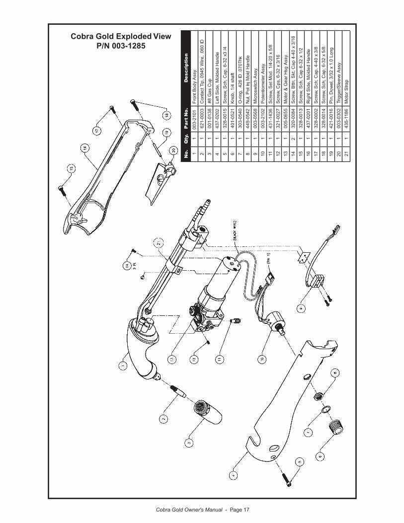
Cobra Gold Exploded ViewP/N 003-1285
.oN
.ytQ
.oN
traP
noitpircseD
11
1012-300.yss
Aydo
BtnorF
21
3000-126DI
060.,eriW
5490,piTtcatnoC
31
8310-100pu
Csa
G8#
41
2020-734eldna
Hdedlo
M,ediStfeL
51
5100-8234/
3x23-6,pa
C,hcS,
wercS
61
1250-104tfahs
4/1,bonK
71
0450-303khT070.
DI624.,gnir-
O
81
2450-944eldna
Hdlo
MjnItoP,tu
N
91
8650-300.yss
Ahcti
wsorciM
011
2012-300.yss
Arete
moitnetoP
111
6341-1348/5
x02-4/1.do
MteS,
wercS
211
7200-12361/3
x23-6,sp
C,werc
S
311
5560-500.yss
Ags
Hrae
G&
rotoM
412
4800-02361/3
x04-4
paC,tk
S,nttB,
wercS
511
3100-8232/1
x23-6
paC,hc
S,werc
S
611
1020-734eldna
Hdedlo
M,ediSthgi
R
711
2000-8238/3
x04-4,pa
C,hcS,
wercS
811
4100-8238/5
x23-6,pa
C,hcS,
wercS
911
6100-124gnoL
0.1x
23/3,lewo
D,niP
021
2030-300.yss
Aeveel
S/reggirT
121
6811-534part
Sroto
M

Cobra Gold Owner's Manual - Page 18
Cobra Gold Front Body Assembly with Motor & Gear HousingP/N 003-2101 and P/N 005-0655
.oN .ytQ .oNtraP noitpircseD
1 1 3341-134 tnorF,eriW,ediuG
2 1 4341-134 raeR,eriW,ediuG
3 1 4701-123 2/1x23-6,teS,wercS
4 1 2650-100 saG,evlaV
5 1 3000-823 2/1x04-4,paC,hcS,wercS
6 1 4800-333 4#,kcoLrpS,rehsaW
7 1 7591-300 gnisuoHraeG,yssA
8 1 4560-500 mreT/W1:5.91doMrotoM
9 1 6811-534 partS
01 1 9510-114 feileRniartS
11 1 6120-823 61/3x84-3,hcS,wercS

Cobra Gold Owner's Manual - Page 19
Cobra Gold Gearbox Assembly P/N 003-1957
.oN .ytQ .oNtraP noitpircseD1 1 5341-134 gnisuoHraeG,daeHelgnA°09
2 1 7870-300 .yssAtfahStuptuO
3 1 1010-115 dloGarboC,lloRevirD
4 1 8910-313 lanretnI,reniateRgniR
5 1 1470-153 091.0x42-01,liocileH
6 1 1000-115 yssAlloRreldI
7 1 2800-333 01#,kcoL,rehsaW
8 1 6020-523 8/3x42-01,HP,wercS
9 1 0200-914 sserpmoC,gnirpS
01 1 5100-134 tsujdA,mrAreldI,wercS
11 1 9400-314 enihcaM,mrAreldI
21 1 6013-124 4/3x8/1,lewoD,niP

Cobra Gold Owner's Manual - Page 20
K1589 Series Ultra-Flex Air Cooled Lead Assy
seilbmessAelbaCxelF-artlUseireS112 seilbmessAelbaCxelF-artlUseireS112 seilbmessAelbaCxelF-artlUseireS112 seilbmessAelbaCxelF-artlUseireS112 seilbmessAelbaCxelF-artlUseireS112
htgneL htgneL htgneL htgneL htgneLetelpmoC etelpmoC etelpmoC etelpmoC etelpmoC
*yssAelbaC *yssAelbaC *yssAelbaC *yssAelbaC *yssAelbaCtiudnoCN/PEL tiudnoCN/PEL tiudnoCN/PEL tiudnoCN/PEL tiudnoCN/PEL
)N/PKM( )N/PKM( )N/PKM( )N/PKM( )N/PKM(rewoP rewoP rewoP rewoP rewoP*elbaC *elbaC *elbaC *elbaC *elbaC
lacirtcelE lacirtcelE lacirtcelE lacirtcelE lacirtcelE*elbaC *elbaC *elbaC *elbaC *elbaC
*esoHsaG *esoHsaG *esoHsaG *esoHsaG *esoHsaGekanS ekanS ekanS ekanS ekanS*nikS *nikS *nikS *nikS *nikS
m5.4/’51 6720-5008-87932S)7000-516(
7252-100 8620-500 7350-100 0110-139
m6.7/’52 772-5006-87932S)8000-516(
8252-100 9620-500 8350-100 2210-139
m2.51/’05 082-5007-87932S)8600-516(
2401-100 2720-500 5660-100 3210-139
srebmuNtraPKM*
)seires112(xelF-artlUrofsgnittiFelbaC )seires112(xelF-artlUrofsgnittiFelbaC )seires112(xelF-artlUrofsgnittiFelbaC )seires112(xelF-artlUrofsgnittiFelbaC )seires112(xelF-artlUrofsgnittiFelbaCelbaCrewoP elbaCrewoP elbaCrewoP elbaCrewoP elbaCrewoP gnittiFdnEhcroT gnittiFdnEhcroT gnittiFdnEhcroT gnittiFdnEhcroT gnittiFdnEhcroT yssAguLdnEtenibaC yssAguLdnEtenibaC yssAguLdnEtenibaC yssAguLdnEtenibaC yssAguLdnEtenibaC
.oNtraP → 8211-134 8231-300
esoHsaG esoHsaG esoHsaG esoHsaG esoHsaG tresnI&tuN tresnI&tuN tresnI&tuN tresnI&tuN tresnI&tuN elurreF elurreF elurreF elurreF elurreF
.oNtraP → 4640-357 1610-964

Cobra Gold Owner's Manual - Page 21
K1590 Series Water Cooled Lead Assy.
K1590 Series Water Cooled Lead Assy.
seilbmessAelbaCdelooCretaWseireS012
htgneL etelpmoC*yssAelbaC
tiudnoCN/PEL)N/PKM(
/retaW4#*elbaCrewoP
lacirtcelE*elbaC
saG*esoH
retaW*esoH
ekanS*nikS
m5.4/’51 7000-5168-87932S)7000-516(
1252-100 8620-500 7350-100 9250-100 0110-139
m6.7/’52 8000-5166-87932S)8000-516(
4252-100 9620-500 8350-100 0350-100 2210-139
m2.51/’05 8600-5167-87932S)8600-516(
8330-348 2720-500 5660-100 7660-100 3210-139
srebmuNtraPKM*
)seires012(sehcroTdelooC-retaWrofsgnittiFelbaCelbaCrewoP/retaW gnittiFdnEhcroT gnittiFdnEhcroT gnittiFdnEhcroT gnittiFdnEhcroT gnittiFdnEhcroT yssAguLdnEtenibaC yssAguLdnEtenibaC yssAguLdnEtenibaC yssAguLdnEtenibaC yssAguLdnEtenibaC ae1056#elurreF ae1056#elurreF ae1056#elurreF ae1056#elurreF ae1056#elurreF
.oNtraP → 0950-300 7231-300 2000-964
esoHsaG tresnI&tuN tresnI&tuN tresnI&tuN tresnI&tuN tresnI&tuN elurreF elurreF elurreF elurreF elurreF
.oNtraP → 4640-357 1610-964
esoHretaW elppiN elppiN elppiN elppiN elppiN tuN tuN tuN tuN tuN elurreF elurreF elurreF elurreF elurreF
.oNtraP → 6560-357 9733-357 1610-964

Cobra Gold Owner's Manual - Page 22
Electrical Control Cable
elbaClortno
CsehcroT
"W"
0973-100,9873-100,8873-100,7873-100
sreb
mu
Ntra
P0973-100,
9873-100,8873-100,7873-100sre
bm
uN
traP
0973-100,9873-100,8873-100,7873-100
sreb
mu
Ntra
P0973-100,
9873-100,8873-100,7873-100sre
bm
uN
traP
0973-100,9873-100,8873-100,7873-100
sreb
mu
Ntra
P .o
N.
oN
.o
N.
oN
.o
N.yt
Q.yt
Q.yt
Q.yt
Q.yt
Q.
oN
traP
.o
Ntra
P.
oN
traP
.o
Ntra
P.
oN
traP
noit
pircseD
noit
pircseD
noit
pircseD
noit
pircseD
noit
pircseD
11
2230-351"
W",niP
7,rotcennoC
21
4000-103too
B
31
5200-114p
malC
4elbaT
4Q
4Q
4Q
4Q
4Q
0700-448.a
G22,dno
C7,elba
C
5tf03.0
4000-9378/1
Ø,knirhS,gnibuT
61
2670-504etani
maLfleS,lebaL
71
9510-114gniniate
R,pmal
C
81
7800-133enerpoe
N,talF,rehsa
W
91
3420-114N
aiD
4/3werc
S4#
eriW
eiT
tsiL
eriW
tsiL
eriW
tsiL
eriW
tsiL
eriW
tsiL
eriW
niP
niP
niP
niP
niP
rol
oC
eriW
rol
oC
eriW
rol
oC
eriW
rol
oC
eriW
rol
oC
eriW
noit
pircseDla
ngi
Sn
oitpircse
Dlan
giS
noit
pircseDla
ngi
Sn
oitpircse
Dlan
giS
noit
pircseDla
ngi
S
Ade
Rroto
MhcroT
Bkcal
Broto
MhcroT
Ceul
Bto
P
Dneer
Grepi
WtoP
En
worB
reggirT
Fegnar
OreggirT
Getih
Wto
P
:4Q
elbaT4#
metIr
ofderi
uqe
Rytit
nau
Q4#
metIr
ofderi
uqe
Rytit
nau
Q4#
metIr
ofderi
uqe
Rytit
nau
Q4#
metIr
ofderi
uqe
Rytit
nau
Q4#
metIr
ofderi
uqe
Rytit
nau
Q.
oN
traP
.o
Ntra
P.
oN
traP
.o
Ntra
P.
oN
traP
noit
pircseD
noit
pircseD
noit
pircseD
noit
pircseD
noit
pircseD
.ytQ
0700-448.yt
Q0700-448
.ytQ
0700-448.yt
Q0700-448
.ytQ
0700-4487873-100
elbaClortno
C'51t
F05.51
8873-100elba
ClortnoC'52
tF
05.52
9873-100elba
ClortnoC'03
tF
05.03
0973-100elba
ClortnoC'05
tF
05.05

Cobra Gold Owner's Manual - Page 23
Cobra Gold Electrical
AF
GE
D CB
"W"
Clo
cked
Am
phen
ol C
onne
ctor
Vie
wed
from
fron
t of c
onne
ctor

Cobra Gold Owner's Manual - Page 24
ALABAMAAIRGAS – SOUTH, INC.Birmingham, AL205/251-6835
INDUSTRIAL WELDING SERVICESQuinton, AL205/674-3258
WELDING ENGINEERING SUPPLY CO.Prichard, AL334/457-8681
WELDING MACHINE HOSPITALMontgomery, AL334/832-9353
ARIZONAPRAXAIR DISTRIBUTION, INC.Phoenix, AZ602/269-2151
ALLSTATE ELECTRIC MOTOR CO.Phoenix, AZ602/233-0500
ARKANSASAPPLIED SERVICES, INC.Benton, AR501/860-6464
ARKANSAS WELDING IND’L SUPPLYHot Springs, AR501/321-9922
EL DORADO WELDING & IND’L SUPPLYEl Dorado, AR870/863-4088
CALIFORNIAADVANCED WELDER REPAIRCommerce, CA323/263-7383
AIRGAS - WEST, INC.Gardena, CA310/523-9355
ALL PHASE WELDER REPAIR & CONSULTINGSacramento, CA916/331-0595
ARC PRODUCTSSan Diego, CA619/628-1022
ARCO WELDER REPAIRSanta Fe Springs, CA562/921-5240
ARK WELDER REPAIRFresno, CA559/486-2251
CAL-WELD SUPPLYFresno, CA209/445-0131
DELTA-TECHSun Valley, CA818/767-4234
EMCO EASTConcord, CA925/798-4411
FRESNO OXYGENFresno, CA559/233-6684
INDUSTRIAL WELDER REPAIRLaPuente, CA626/961-7643
PRAXAIR DISTRIBUTION, INC.Long Beach, CA562/427-0099
PRAXAIR DISTRIBUTION, INC.Bakersfield, CA661/321-9922
R. J. KATESSan Diego, CA619/565-6960
RED-D-ARC, INC.Carson, CA310/233-3327
SOUTHWEST WELDER REPAIRFontana, CA909/357-1661
MK Warranty Repair Centers as of 11/13/2001Check www.mkprod.com for a current, accurate listing.

Cobra Gold Owner's Manual - Page 25
SWEINHART ELECTRIC CO., INC.Long Beach, CA714/521-9100
COLORADOAIRGAS - INTERMOUNTAIN, INC.Colorado Springs, CO719/473-1947
WELDERS & EQUIP. SVC. & TESTINGLittleton, CO303/932-8755
WESTERN SLOPE WELDER REPAIRGrand Junction, CO970/243-9616
FLORIDAA & I SPECIALTIESLehigh Acres, FL941/368-7435
ACTION WELDING SUPPLYJacksonville, FL904/786-2254
AMVEL CORPORATIONMiami, FL305/592-5678
ELECTRICAL WELDERS SERVICEOrlando, FL407/999-5214
HAUN SYSTEMS REPAIR, INC.Orlando, FL407/681-6064
HOLOXOcala, FL352/351-4417
J.K. CIRCUIT TECHNOLOGYBoynton Beach, FL561/733-7859
ROPER ELECTRIC MOTOR SERVICEPanama City, FL850/769-6643
SMITTY’S WELDER SERVICEWest Palm Beach, FL561/845-1224
TRI-GASMiami, FL305/592-3180
TRI-STATE SALES & LEASINGLake City, FL904/397-3340
TRI-TECHSarasota, FL941/758-3825
V.A. ELECTRICAL MOTORS CENTERHialeah, FL305/825-3327
GEORGIAB&W INDUSTRIAL SERVICESAugusta, GA706/738-8722
Mc CULLOUGH ELEC. MOTOR SVC.Atlanta, GA404/688-5251
HAWAIIDC ELECTRIC, INC.Aiea, HI808/483-8900
IDAHONORCOBoise, ID208/336-1643
ILLINOISINDUSTRIAL WELDER REBUILDERSAlsip, IL708/371-5688
RELIABLE EQUIPMENT REPAIRHamel, IL618/633-5000
SCHERER INDUSTRIAL GROUP, INC.Galesburg, IL309/342-4125 or 888/964-3526
INDIANAAGA GAS, INC.Hammond, IN219/989-9030
MK Warranty Repair Stations as of 11/13/2001 (Continued)

Cobra Gold Owner's Manual - Page 26
AIRGAS-MID AMERICA, INC.Evansville, IN800/424-8905
B & H ELECTRICSeymour, IN812/522-5607
COX EQUIPMENT COMPANYIndianapolis, IN317/241-8881
EVANSVILLE ARMATURE, INC.Evansville, IN812/428-9034
MODERN SUPPLY CO., INC.Evansville, IN812/425-9353
PRAXAIR DISTRIBUTION, INC.Speedway, IN317/481-4550
SUTTON-GARTEN COMPANYIndianapolis, IN317/264-3236
IOWAAIRGAS NORTH CENTRALDes Moines, IA515/266-1111
CEDAR RAPIDS WELDING SUPPLYCedar Rapids, IA319/365-1466
ELECTRICAL ENGRG. & EQUIPMENTDes Moines, IA515/266-8890
WRIGHT WELDING SUPPLYFt. Dodge, IA515/576-0640
KANSASKANOXHutchinson, KS316/665-5551
KENTUCKYGENERAL WELDING PRODUCTSLouisville, KY502/635-5218
RED-D-ARCLexington, KY800/245-3660
WELDING EQUIPMENTLouisville, KY502/636-0545
LOUISIANARED BALL OXYGEN CO.Shreveport, LA318/425-3211
MarylandCCM Mech/Elec Repair Service, Inc.Owings, MD301/855-7508
MICHIGANANN ARBOR WELDING SUPPLY CO.Ypsilanti, MI734/572-0444
APEX WELDING GASES & SUPPLYMuskegon Heights, MI616/722-3185
AUTOMATIC WELDMidland, MI517/496-9245
GREAT LAKES EQUIPMENTClare, MI517/386-4630
HAMILTON ELECTRIC CO.Saginaw, MI517/799-6291
SAGINAW WELDING SUPPLY CO.Saginaw, MI517/793-9696
SOUTHPARK WELDINGMarysville, MI810/364-6521
WELDING METALS, INC.Madison Heights, MI248/585-0480
WESAR COMPANYThree Rivers, MI616/483-9125
MK Warranty Repair Stations as of 11/13/2001 (Continued)

Cobra Gold Owner's Manual - Page 27
MINNESOTAMINNEAPOLIS OXYGEN CO.Minneapolis, MN612/588-8855
OXYGEN SERVICE CO.St. Paul, MN612/644-7273
MISSOURICEE-KAY SUPPLY, INC.St. Louis, MO324/644-3500
P.G. WALKERSpringfield, MO417/862-1745
MISSISSIPPINORDAN SMITH WELDING SUPPLYHattiesburg, MS601/545-1800
3D SUPPLIES, INC.Jackson, MS601/353-3330
NEVADASIERRA WELDING SUPPLY CO.Sparks, NV775/359-0542
NEW JERSEYINDUSTRIAL ELECTRIC SERVICE CO.Hawthorne, NJ973/423-1212
NEW YORKDELO WELDING SUPPLYSyracuse, NY315/478-2188
HAUN WELDING SUPPLYSyracuse, NY315/463-5241
NORTH CAROLINAHOLOX LTD.Colfax, NC336/996-1974
M & L WELDER REPAIRAsheville, NC828/250-9353
MACHINE & WELDING SUPPLY CO.Dunn, NC910/892-4016
MACHINE AND WELDING SUPPLY CO.Greenville, NC252/752-3089
MACHINE AND WELDING SUPPLY CO.Raleigh, NC919/772-9500
MACHINE AND WELDING SUPPLY CO.Winston-Salem, NC336/723-9651
NATIONAL WELDERS SUPPLY CO.High Point, NC910/882-1110
NATIONAL WELDERS SUPPLY CO.Charlotte, NC704/392-7317
OHIOAGA GASES, INC.Lima, OH419/228-2828
ALBRIGHT WELDING SUPPLYWooster, OH330/264-2021
ARC EQUIPMENT COMPANYStruthers, OH333/750-9353
ARC SERVICES, INC.Toledo, OH419/478-6204
BELAIR PRODUCTS, INC.Akron, OH330/253-3116
BIG RIVER ELECTRICGallipolis, OH740/446-4360
CnD MACHINE, INC.Canton, OH330/478-8811
MK Warranty Repair Stations as of 11/13/2001 (Continued)

Cobra Gold Owner's Manual - Page 28
OHIO AIR PRODUCTSCanton, OH330/821-2771
RICK’S WELDER REPAIR SERVICEEastlake, OH440/269-1204
VALLEY NATIONAL GASESHilliard, OH614/771-1311
VALLEY NATIONAL GASESLima, OH419/228-1008
VALLEY NATIONAL GASESToledo, OH419/241-9114
VOLLMER ELECTRIC CO.Columbus, OH614/476-8800
WEILER WELDING CO., INC.Dayton, OH937/222-8312
WELDINGHOUSE, INC.Cleveland, OH216/524-1955
OKLAHOMAAIRGAS MID-SOUTHTulsa, OK918/582-0885
BILL’S WELDER REPAIROklahoma City, OK405/232-4799
MUNN SUPPLYEnid, OK580/234-4120
OKLAHOMA WELDERS SUPPLYMadill, OK580/795-5561
OREGONE C COMPANYdba ELECTRICAL CONSTRUCTION CO.Portland, OR800/452-1511
INDUSTRIAL SOURCEEugene, OR541/344-1438
PENNSYLVANIAALLWELD EQUIPMENT REPAIRPittsburgh, PA412/821-8460
GEOVIC WELDING SUPPLYMilton, PA717/742-9377
J.A. CUNNINGHAM EQUIPMENT, INC.Philadelphia, PA215/426-6650
POWER SOURCE REPAIR CO., INC.Collingdale, PA610/532-6460
VALLEY NATIONAL GASESPittsburgh, PA412/281-1835
SOUTH CAROLINACAROLINA WELDER SERVICELake City, SC843/687-0413
TENNESSEENEXAIRMemphis, TN901/523-6821
TRAMCOBristol, TN423/968-4499
NATIONAL RENTAL & REPAIRKnoxville, TN423/584-6390
TEXASAIRGAS - SOUTHWEST, INC.Austin, TX512/835-0202
AIRGAS - SOUTHWEST, INC.Houston, TX713/462-8027
DENISON OXYGENDenison, TX903/465-3369
MK Warranty Repair Stations as of 11/13/2001 (Continued)

Cobra Gold Owner's Manual - Page 29
FT. WORTH WELDERS SUPPLY, INC.Fort Worth, TX817/332-8696
GPC SERVICES, INC.San Angelo, TX915/655-4545
RITE-WELD SUPPLY, INCFort Worth, TX817/626-8237
UTAHC.W. SILVER INDUSTRIAL SERVICESalt Lake City, UT801/531-8888
VIRGINIAAIR PRODUCTS & CHEMICALS, INC.Bristol, VA540/669-3161
ARC WELDERS, INC.Ashland, VA804/798-1818
NORFOLK WELDERS SUPPLYNorfolk, VA804/622-6571
WASHINGTONAIRGAS - NORPAC, INC.Tacoma, WA253/473-2282
A-L WELDING PRODUCTSTukwila, WA425/228-2218
AMERICAN EQUIPMENT SERVICESKent, WA253/395-9947
HARRIS ELECTRIC, INC.Seattle, WA206/782-6668
OXARC, INC.Spokane, WA509/535-7794
PACIFIC WELDING SUPPLIESTacoma, WA253/572-5302
PRECISION WELDER & ENGINE REPAIRSeattle, WA206/382-6227
WEST VIRGINIACARDINAL SALES & SERVICE, INC.Clarksburg, WV304/622-7590
WISCONSININTERSTATE WELDING SALES CORP.Appleton, WI920/734-7173
PRAXAIR DISTRIBUTION, INC.Brookfield, WI414/938-6365
WELDER REPAIR & SERVICE, INC.Fredonia, WI262/692-3068
CANADAA&A WELDER SERVICES LTD.Saskatoon, Saskatchewan306/934-1601
ARC & GENERATOR REPAIRGarson, Ontario705/525-2141
B. HARRIS WELDING SVCS. LTD.Dartmouth, Nova Scotia902/468-6255
BARRY HAMEL EQUIPMENT LTD.Coquitlam, B.C.604/945-9313
ELECTRO-MÉCANIK, INC.Sainte-Foy, Quebec418/683-1724
GPR INDUSTRIES 1994 LTD.Grande Prairie, Alberta780/532-5900
HYPERDYNAMICS TECHNOLOGIES LTD.Pickering, Ontario905/683-9938
INDUSTRIAL ELECTRONIC SERVICESCalgary, Alberta403/279-3432
MK Warranty Repair Stations as of 11/13/2001 (Continued)

Cobra Gold Owner's Manual - Page 30
WELDERS SUPPLYWinnipeg, Manitoba204/772-9476
WELDING WIDE SERVICES, INC.Brampton, Ontario905/874-9992
WELDTECB.C.604/545-3886
CHINAPHT Group CompanyBeijing, China86-10-6858 8395
MK Warranty Repair Stations as of 11/13/2001 (Continued)LADEL LTD.Quebec819/376-6577
M.R.T. REPAIR CENTER, INC.Montreal, Quebec514/648-0800
OZARK ELECTRICAL MARINE LTD.St. Johns, Newfoundland709/726-4554
PEEL ENGINESMississauga, Ontario905/670-1535
PROMOTECH ÉLECTRIQUE, INC.Fleurimont, Quebec819/822-2111

THIS PAGE INTENTIONALLY BLANK


Effective March 1, 2001This warranty supersedes all previous MK Products warranties and is
exclusive, with no other guarantees or warranties expressed or implied.
LIMITED WARRANTY - MK Products,Inc.,Irvine,California warrants that all new and unused equipment furnished by MK Products is free from defect in workmanship and material as of the time and place of delivery by MK Products. No warranty is made by MK Products with respect to trade accessories or other items manufactured by others. Such trade accessories and other items are sold subject to the warranties of their respective manufacturers, if any.
MK Products’ warranty does not apply to components having normal useful life of less than one (1) year, such as relay points, wire conduit, tungsten, and welding torch parts that come in contact with the welding wire, including gas cups, gas cup insulators, and contact tips where failure does not result from defect in workmanship or material.
In the case of MK Products’ breach of warranty or any other duty with respect to the quality of any goods, the exclusive remedies therefore shall be at MK Products’ option:
(1) repair(2) replacement(3) where authorized in writing by MK Products, the reason-able cost of repair or replacement at our Irvine, California plant; or(4) payment of or credit for the purchase price (less reason-able depreciation based upon actual use) upon return of the goods at customer’s risk and expense. Upon receipt of notice of apparent defect or failure, MK Products shall instruct the claimant on the warranty claim procedures to be followed.
As a matter of general policy only, MK Products may honor an original user’s warranty claims on warranted equipment in the event of failure resulting from a defect within the following periods from the date of delivery of equipment to the original user:
1. Torches, Weldheads and Water Recirculators...........1 year2. All Other Equipment...................................................3 years3. Repairs ...................................................................... 90 days
Classification of any item into the foregoing categories shall be at the sole discretion of MK Products. Notification of any failure must be made in writing within 30 days of such failure.
A copy of the invoice showing the date of sale must accom-pany products returned for warranty repair or replacement.
All equipment returned to MK Products for service must be properly packaged to guard against damage from shipping. MK Products will not be responsible for any damages result-ing from shipping.
Normal surface transportation charges (both ways) for prod-ucts returned for warranty repair or replacement will be borne by MK Products, except for products sold to foreign markets.
ANY EXPRESS WARRANTY NOT PROVIDED HEREIN AND ANY IMPLIED WARRANTY, GUARANTY, OR REPRESENTATION AS TO PERFORMANCE, AND ANY REMEDY FOR BREACH OF CONTRACT WHICH, BUT FOR THIS PROVISION, MIGHT ARISE BY IMPLICATION, OPERATION OF LAW, CUSTOM OF TRADE, OR COURSE OF DEALING, INCLUDING ANY IMPLIED WARRANTY OF MERCHANTABILITY OR OF FITNESS FOR PARTICULAR PURPOSE, WITH RESPECT TO ANY AND ALL EQUIPMENT FURNISHED BY MK PRODUCTS, IS EXCLUDED AND DISCLAIMED BY MK PRODUCTS.
EXCEPT AS EXPRESSLY PROVIDED BY MK PRODUCTS IN WRITING, MK PRODUCTS ARE INTENDED FOR ULTIMATE PURCHASE BY COMMERCIAL/INDUSTRIAL USERS AND FOR OPERATION BY PERSONS TRAINED AND EXPERIENCED IN THE USE AND MAINTENANCE OF WELDING EQUIPMENT AND NOT FOR CONSUMERS OR CONSUMER USE. MK PRODUCTS WARRANTIES DO NOT EXTEND TO, AND NO RE-SELLER IS AUTHORIZED TO EXTEND MK PRODUCTS’ WARRANTIES TO ANY CONSUMER.
16882 Armstrong Ave.Irvine, CA 92606Tel (949)863-1234Fax (949)474-1428
DATE : March 1, 2001
Sales and Service through Subsidiaries and Distributors Worldwide
Cleveland, Ohio 44117-1199 U.S.A. TEL: 216.481.8100 FAX: 216.486.1751 WEB SITE: www.lincolnelectric.com
World’s Leader in Welding and Cutting Products
LINCOLNELECTRIC
®


![GMAW chapter22[1]](https://img.pdfslide.us/doc/110x75/577d22881a28ab4e1e97a08e/gmaw-chapter221.jpg)