Embed Size (px)
Citation preview
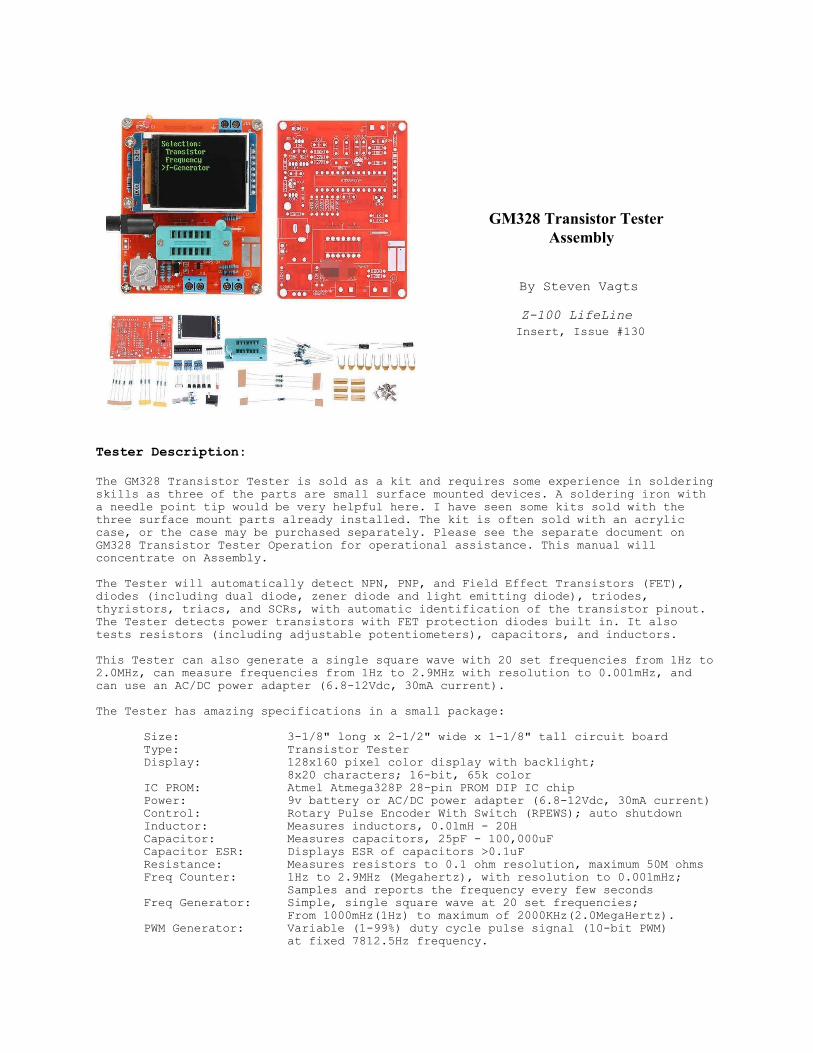
GM328 Transistor Tester Assembly
By Steven Vagts
Z-100 LifeLine Insert, Issue #130
Tester Description:
The GM328 Transistor Tester is sold as a kit and requires some experience in solderingskills as three of the parts are small surface mounted devices. A soldering iron witha needle point tip would be very helpful here. I have seen some kits sold with thethree surface mount parts already installed. The kit is often sold with an acryliccase, or the case may be purchased separately. Please see the separate document onGM328 Transistor Tester Operation for operational assistance. This manual willconcentrate on Assembly.
The Tester will automatically detect NPN, PNP, and Field Effect Transistors (FET),diodes (including dual diode, zener diode and light emitting diode), triodes,thyristors, triacs, and SCRs, with automatic identification of the transistor pinout.The Tester detects power transistors with FET protection diodes built in. It alsotests resistors (including adjustable potentiometers), capacitors, and inductors.
This Tester can also generate a single square wave with 20 set frequencies from 1Hz to2.0MHz, can measure frequencies from 1Hz to 2.9MHz with resolution to 0.001mHz, andcan use an AC/DC power adapter (6.8-12Vdc, 30mA current).
The Tester has amazing specifications in a small package:
Size: 3-1/8" long x 2-1/2" wide x 1-1/8" tall circuit boardType: Transistor TesterDisplay: 128x160 pixel color display with backlight;
8x20 characters; 16-bit, 65k colorIC PROM: Atmel Atmega328P 28-pin PROM DIP IC chipPower: 9v battery or AC/DC power adapter (6.8-12Vdc, 30mA current)Control: Rotary Pulse Encoder With Switch (RPEWS); auto shutdownInductor: Measures inductors, 0.01mH - 20HCapacitor: Measures capacitors, 25pF - 100,000uFCapacitor ESR: Displays ESR of capacitors >0.1uFResistance: Measures resistors to 0.1 ohm resolution, maximum 50M ohmsFreq Counter: 1Hz to 2.9MHz (Megahertz), with resolution to 0.001mHz;
Samples and reports the frequency every few secondsFreq Generator: Simple, single square wave at 20 set frequencies;
From 1000mHz(1Hz) to maximum of 2000KHz(2.0MegaHertz).PWM Generator: Variable (1-99%) duty cycle pulse signal (10-bit PWM)
at fixed 7812.5Hz frequency.
Features:- Automatically checks the component’s pins and displays them on the LCD.- Automatic detection of NPN and PNP transistors, N-channel and P-channel MOSFETs, diodes (Zener diodes <4.5 Vdc, dual diodes and LEDs), triodes, thyristors, triacs, resistors, inductors, capacitors (including ESR).- Measures adjustable potentiometers, if wiper not positioned at one end.- Measures capacitor ESR of capacitors >0.1uF, with resolution of 0.01 ohms.- Measures the rate of decline (Vloss) of Capacitors >5000pF (Q value).- Can identify zener diodes whose reverse breakdown voltage is <4.5 Vdc.- Measures bipolar transistor current amplification factor and base-emitter
threshold voltage.- Measures the reverse capacitance of a single diode.- Measures the collector or emitter junction reverse capacitance of bipolar transistors.- Measures the gate threshold voltage and gate capacitance of a MOSFET.- In the transistor, the MOSFET protection diode's amplification factor and base can be sensed to determine the forward bias voltage of the emitter transistor.- Measures frequencies from 1Hz to 2.9MHz (Megahertz).- Square wave generator for 20 set frequencies between 1Hz to 2MHz.- PWM square wave generator with variable (1-99%) duty cycle pulse signal (10-bit PWM) at fixed 7812.5Hz frequency.
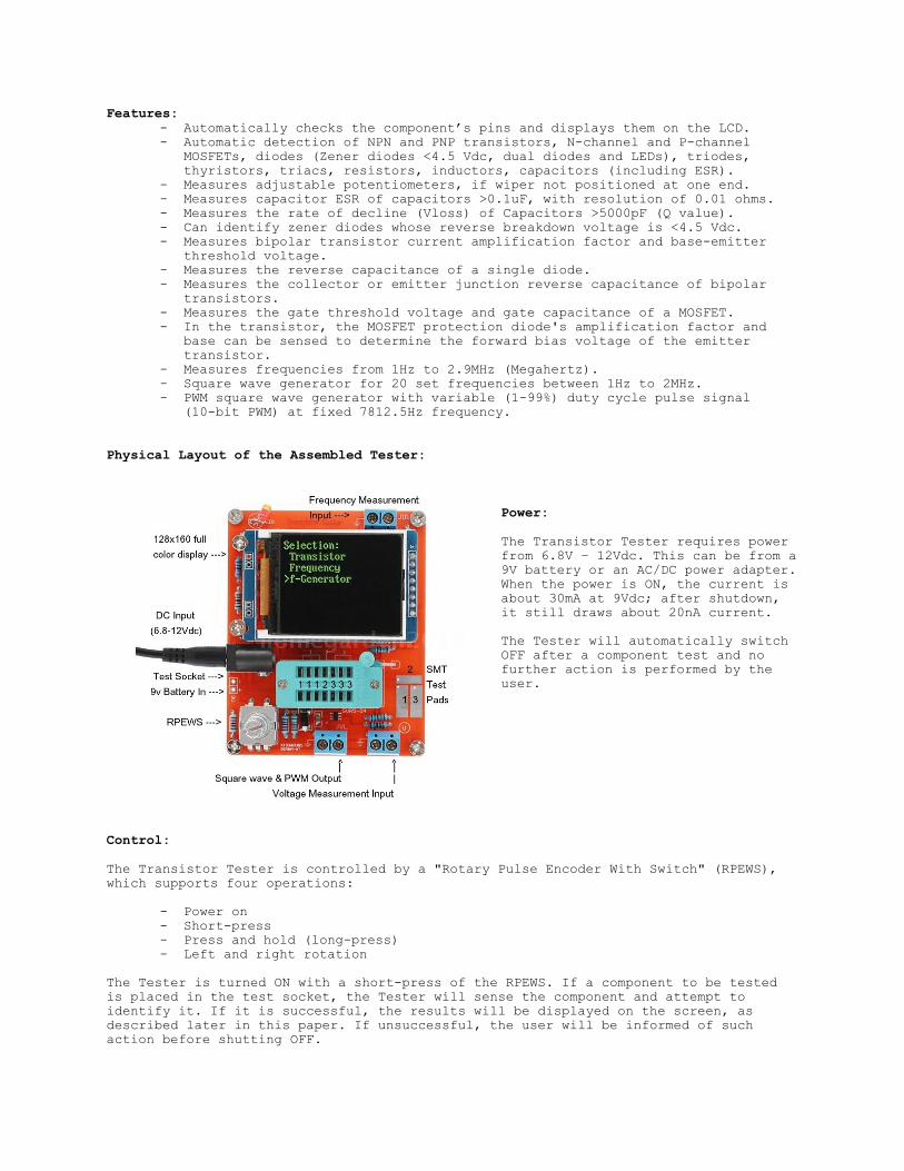
Physical Layout of the Assembled Tester:
Power:
The Transistor Tester requires powerfrom 6.8V – 12Vdc. This can be from a9V battery or an AC/DC power adapter.When the power is ON, the current isabout 30mA at 9Vdc; after shutdown,it still draws about 20nA current.
The Tester will automatically switchOFF after a component test and nofurther action is performed by theuser.
Control:
The Transistor Tester is controlled by a "Rotary Pulse Encoder With Switch" (RPEWS),which supports four operations:
- Power on- Short-press- Press and hold (long-press)- Left and right rotation
The Tester is turned ON with a short-press of the RPEWS. If a component to be testedis placed in the test socket, the Tester will sense the component and attempt toidentify it. If it is successful, the results will be displayed on the screen, asdescribed later in this paper. If unsuccessful, the user will be informed of suchaction before shutting OFF.

Following the component check, and before automatically shutting OFF, the unit willwait 15 seconds for user action. A long-press OR rotation of the RPEWS left or rightwill enter the Function Menu. In the Function Menu, a ">" in the left column indicatesthe present menu item selected. To select another function, rotate the RPEWS left orright and do a short-press on the function selected.
To exit a Function, press and hold (long-press) the RPEWS knob until you are returnedto the Function Menu.
Assembly:
Note: For a full, more detailed article on the assembly of the GM328 TransistorTester, please check out the website:
https://www.instructables.com/id/Circuit-Circus-in-Depth-Tech/.
It was created with the novice in mind, with plenty of photographs.
The following description is provided here in the event that the website mentionedabove is removed or becomes not available. This description also assumes a moreexperienced hobbyist and will provide more of a summary of procedures, with somedetails and hints that I found were omitted during my construction. Also, many of thephotos used here are from that website. It is well worth checking it out.
As you can see from the first photograph, all the parts needed to construct the Testerare provided, except that there are NO assembly instructions. Some kits will alsoinclude an acrylic case which is easy to construct, but is beyond the scope of thisdocument.
Assembly will require the following tools:
Ohmmeter and Capacitor Checker (recommended)9v Battery or 6.8-12Vdc AC/DC power adapterNeedle tip soldering iron or gunThin electronics solder w/flux coreFine solder wick or desoldering braid for mistakesNeedle nose pliers or tweezers (optional)Diagonal side cuttersPhillip’s head screwdriverMasking tape
Before beginning construction, identify and compare the parts you received with thefollowing list. I also suggest that you check those parts that you can with an ohm-meter and capacitor checker, if they are available. All parts are new; however, in thethree kits that I have constructed, I found a shorted capacitor and a resistorincluded in one kit of the wrong value. A little extra time here to check componentsnow, will save considerable time trying to troubleshoot a malfunctioning Tester.
Parts List: (Numbers in parentheses show component markings)
Component Description: Number: 220 ohm, 1/4W, 1%, Metal Film Resistor 1 [ ] 680 ohm, 1/4W, 1%, Metal Film Resistor 3 [ ] 1K ohm, 1/4W, 1%, Metal Film Resistor 2 [ ]2.2K ohm, 1/4W, 1%, Metal Film Resistor 1 [ ]3.3K ohm, 1/4W, 1%, Metal Film Resistor 1 [ ] 10K ohm, 1/4W, 1%, Metal Film Resistor 6 [ ] 20K ohm, 1/4W, 1%, Metal Film Resistor 1 [ ] 27K ohm, 1/4W, 1%, Metal Film Resistor 2 [ ] 33K ohm, 1/4W, 1%, Metal Film Resistor 1 [ ]100K ohm, 1/4W, 1%, Metal Film Resistor 1 [ ]180K ohm, 1/4W, 1%, Metal Film Resistor 1 [ ]470K ohm, 1/4W, 1%, Metal Film Resistor 3 [ ] 22pF, 20%, (220), Ceramic Capacitor 2 [ ]
1000pF, 20%, (102), Ceramic Capacitor 1 [ ] 0.01uF, 20%, (103), Ceramic Capacitor 1 [ ] 0.1uF, 20%, (104), Ceramic Capacitor 5 [ ] 0.1uF, 20%, (SMT), Ceramic Capacitor 1 [ ] (surface mount) 10uF, 20%, Aluminum Electrolytic Capacitor 2 [ ]8MHz, Quartz Crystal 1 [ ]9012, PNP TO-92 Bipolar Junction Transistor 1 [ ]9014, NPN TO-92 Bipolar Junction Transistor 2 [ ]HT7550, TO-92 Regulator Transistor 1 [ ]TL431, TO-92 Precision Reference Transistor 1 [ ]ATMega328P-PU AVR MCU w/28-pin socket 1 [ ] (both together)SRV05-4 (MC5) Low Capacitance TVS Diode Array 1 [ ] (surface mount)P6KE6V8 (6V8C) Transient Voltage Suppressor 1 [ ] (surface mount)Red, 03MM, Light Emitting Diode 1 [ ]Test Socket 1 [ ]DC Jack 1 [ ]Rotary Pulse Encoder With Switch (RPEWS) 1 [ ]Connecting Terminal, Blue, 2-pin 3 [ ]Female Connecting Header, 8-pin, SIP 1 [ ]Copper Pillar, 3mm x 11mm 6 [ ]Bolt, 3mm 8 [ ]TFT LCD Module, 120x160 pixel w/16-bit color 1 [ ]Main Circuit Board, 77x60mm 1 [ ]
This Transistor Tester has three surface mount technology (SMT) components, identifiedas ZD (P6KE6V8), CESD (the 0.1uF SMT capacitor), and the ESD (Diode Array). The ESDdiode array may be marked “MC5", “VC5" or “LC5". While some kits come with thesealready installed, most do not. These parts are TINY, in little containers. Do notremove until ready to install them. Take care not to lose them.
As these SMT components are the smallest, they are installed first. Their role is toprotect the MicroController Unit (MCU) against transient high voltage. The Tester canwork normally without these three parts, if you would rather skip their installation,but they provide the only protection of the MCU ports from accidental high voltage.
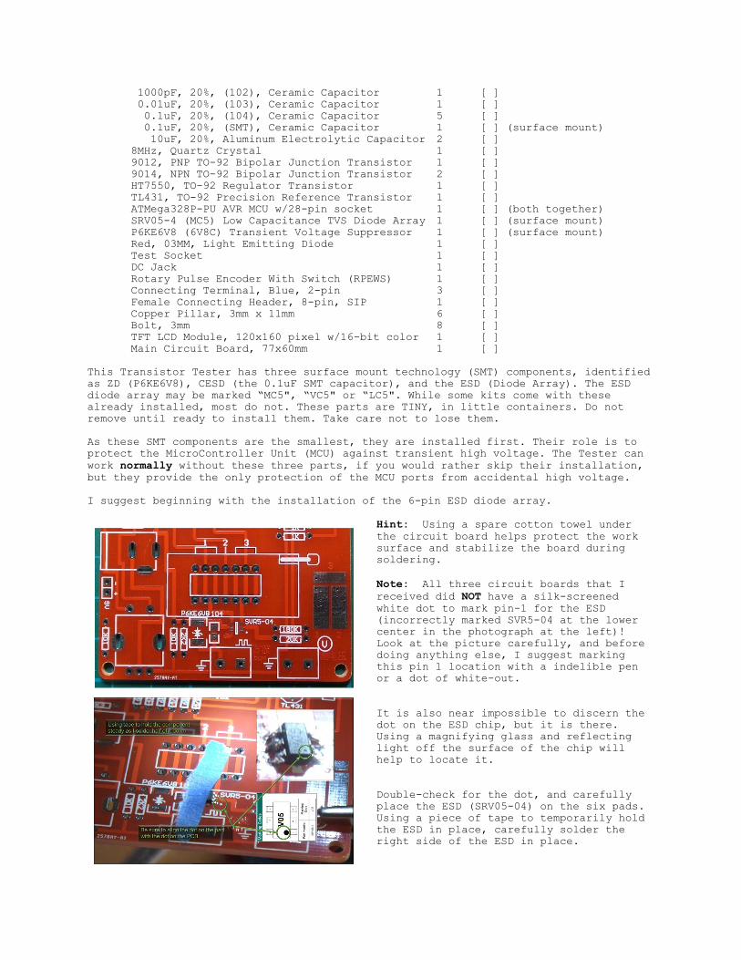
I suggest beginning with the installation of the 6-pin ESD diode array.
Hint: Using a spare cotton towel underthe circuit board helps protect the worksurface and stabilize the board duringsoldering.
Note: All three circuit boards that Ireceived did NOT have a silk-screenedwhite dot to mark pin-1 for the ESD(incorrectly marked SVR5-04 at the lowercenter in the photograph at the left)!Look at the picture carefully, and beforedoing anything else, I suggest markingthis pin 1 location with a indelible penor a dot of white-out.
It is also near impossible to discern thedot on the ESD chip, but it is there.Using a magnifying glass and reflectinglight off the surface of the chip willhelp to locate it.
Double-check for the dot, and carefullyplace the ESD (SRV05-04) on the six pads.Using a piece of tape to temporarily holdthe ESD in place, carefully solder theright side of the ESD in place.
Note: If you accidently create a solder bridge across 2 or 3 pins, place solder wickover the solder bridge and carefully heat the wick only until solder flows into thewick. Take care not to overheat the component!
Remove the tape when satisfied with the solder work on the right side and, AGAINrechecking the dot first, solder the ESD’s left three tabs. Check for shorted pinswith an ohmmeter. Use solder wick if necessary.
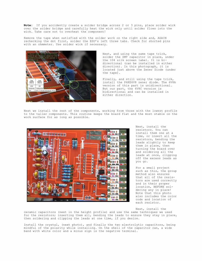
Next, and using the same tape trick,solder the SMT capacitor in place, underthe 104 silk screen label. It is bi-directional (can be installed in eitherdirection). In this photograph, it islocated just above the Zener Diode (underthe tape).
Finally, and still using the tape trick,install the P6KE6V8 zener diode. The 6V8Aversion of this part is unidirectional.But our part, the 6V8C version isbidirectional and can be installed ineither direction.
Next we install the rest of the components, working from those with the lowest profileto the taller components. This routine keeps the board flat and the most stable on thework surface for as long as possible.
Next, install theresistors. You caninstall them one at atime, or insert all theresistors, bending theleads slightly to keepthem in place, thenturning the board overand soldering all theleads at once, clippingoff the excess leads asyou go.
For a small projectsuch as this, the groupmethod also ensuresthat all of the resis-tors are used correctlyand in their properlocation, BEFORE sol-dering any in place!Note that this photoalso includes the colorcode and location ofeach resistor.
Next, install theceramic capacitors (next in the height profile) and use the same techniques we usedfor the resistors; inserting them all, bending the leads to ensure they stay in place,then soldering and clipping the leads at one time, if you desire.
Install the crystal, (next photo), and finally the two electrolytic capacitors, beingmindful of the polarity while installing. On the shell of the capacitor can, a wideband with white color and a minus sign is the negative terminal.
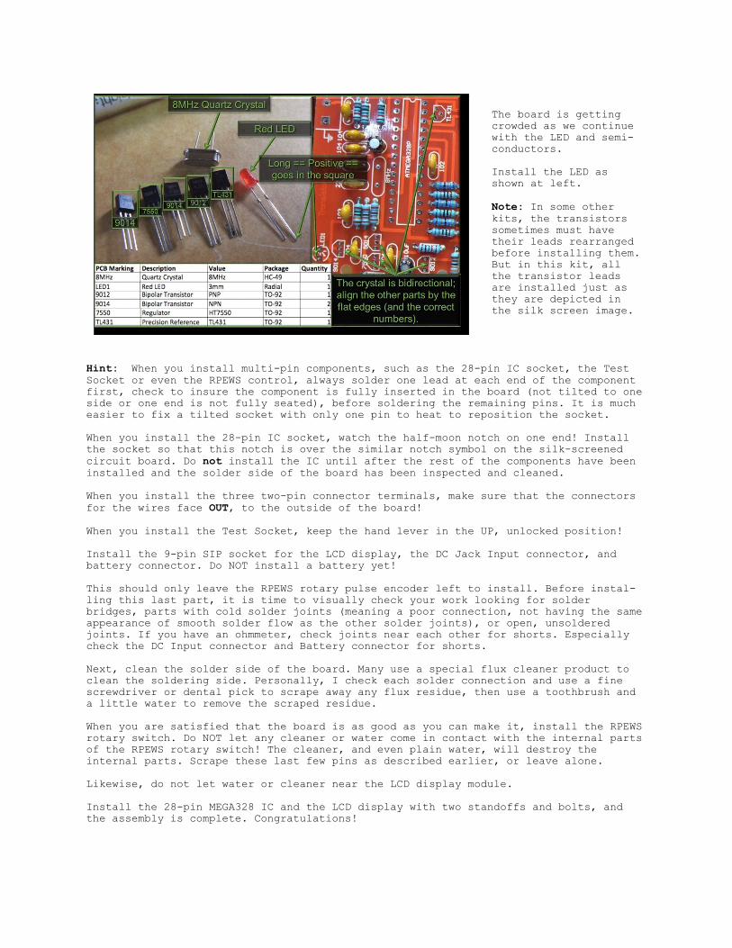
The board is gettingcrowded as we continuewith the LED and semi-conductors.
Install the LED asshown at left.
Note: In some otherkits, the transistorssometimes must havetheir leads rearrangedbefore installing them.But in this kit, allthe transistor leadsare installed just asthey are depicted inthe silk screen image.
Hint: When you install multi-pin components, such as the 28-pin IC socket, the TestSocket or even the RPEWS control, always solder one lead at each end of the componentfirst, check to insure the component is fully inserted in the board (not tilted to oneside or one end is not fully seated), before soldering the remaining pins. It is mucheasier to fix a tilted socket with only one pin to heat to reposition the socket.
When you install the 28-pin IC socket, watch the half-moon notch on one end! Installthe socket so that this notch is over the similar notch symbol on the silk-screenedcircuit board. Do not install the IC until after the rest of the components have beeninstalled and the solder side of the board has been inspected and cleaned.
When you install the three two-pin connector terminals, make sure that the connectorsfor the wires face OUT, to the outside of the board!
When you install the Test Socket, keep the hand lever in the UP, unlocked position!
Install the 9-pin SIP socket for the LCD display, the DC Jack Input connector, andbattery connector. Do NOT install a battery yet!
This should only leave the RPEWS rotary pulse encoder left to install. Before instal-ling this last part, it is time to visually check your work looking for solderbridges, parts with cold solder joints (meaning a poor connection, not having the sameappearance of smooth solder flow as the other solder joints), or open, unsolderedjoints. If you have an ohmmeter, check joints near each other for shorts. Especiallycheck the DC Input connector and Battery connector for shorts.
Next, clean the solder side of the board. Many use a special flux cleaner product toclean the soldering side. Personally, I check each solder connection and use a finescrewdriver or dental pick to scrape away any flux residue, then use a toothbrush anda little water to remove the scraped residue.
When you are satisfied that the board is as good as you can make it, install the RPEWSrotary switch. Do NOT let any cleaner or water come in contact with the internal partsof the RPEWS rotary switch! The cleaner, and even plain water, will destroy theinternal parts. Scrape these last few pins as described earlier, or leave alone.
Likewise, do not let water or cleaner near the LCD display module. Install the 28-pin MEGA328 IC and the LCD display with two standoffs and bolts, andthe assembly is complete. Congratulations!

Introductory Operation:
The Transistor Tester has three Test Points (TP1, TP2,TP3) within the test socket and three pads for surfacemount components.
The Test Points in the test socket are arranged in thepattern displayed on the circuit board silk screen justabove the test socket. The left six (3+3) belong to TP1,the middle two (1+1) belong to TP2, and the right six(3+3) belong to TP3.
To the right of the test socket are three test pads thatcan be used to test surface mount components.
Note: The numbers of the test pads on the silk screened board, if labeled at all, mayNOT be numbered correctly. Please check them with an ohmmeter to match the pins of theTest Socket. Mine had to be labeled as shown in the second picture, above.
When testing two or three lead components, the leads must be placed between differenttest points, that is, place a component in the test socket such that each pin of thecomponent is in a separate test point.
Note: If TP1 and TP3 are selected, the Tester will enter a “series test mode”, whererepeat tests are done automatically. You may change components at any point in thisseries. Exit the series with a long-press of the RPEWS. The test may be started againwith a short-press of the RPEWS.
Self-test & Calibration:
Note: This Tester requires calibration before use.
The Self-test & Calibration can be started by either:
- Shorting all test points and turning the device ON- Selecting it from the Function Menu
Note: To short the Test Points together, simply construct a small test component ofthree short lengths of wire, such as the cut resistor leads from construction, twistedand soldered together.
Upon sensing the shorted test pins, the Tester will prompt with Selftest mode..?and a RPEWS short-press (within 2 seconds) will direct the tester into self-testmode. The color of the Tester's LCD will change to white on a black background.If not short-pressed within 2 seconds, the Tester will resume normal measurement.
The Tester will sense the shorted probes and report:Selftest mode..R0=.32 .35 .30Ù (Yours may be different)
When the test procedure prompts Isolate Probes! ... remove the shorted test componentfrom the test socket. The Tester will sense the disconnection of the Test Points andreport the values of Ri_Hi and Ri_Lo, such as:
Ri_Hi=22.4ÙRi_Lo=20.3Ù
Then it reports C0 on a new page, such as:C0 41 42 47pF,OK
The calibration procedure begins next, if the unit has not been calibrated, byprompting:
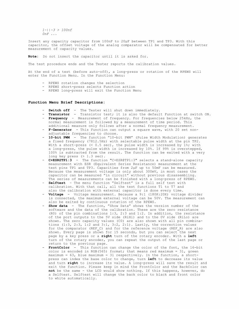
1-||-3 > 100nf0nF ...
Insert any capacity capacitor from 100nF to 20µF between TP1 and TP3. With thiscapacitor, the offset voltage of the analog comparator will be compensated for bettermeasurement of capacity values.
Note: Do not insert the capacitor until it is asked for.
The test procedure ends and the Tester reports the calibration values.
At the end of a test (before auto-off), a long-press or rotation of the RPEWS willenter the Function Menu. In the Function Menu:
- RPEWS rotation changes the selection- RPEWS short-press selects Function action- RPEWS long-press will exit the Function Menu
Function Menu Brief Descriptions:
- Switch off - The Tester will shut down immediately.- Transistor - Transistor test; it is also the default Function at switch ON.- Frequency - Measurement of frequency. For frequencies below 25kHz, the normal measurement is followed by a measurement of time period. This additional measure only follows after a normal frequency measurement.- F-Generator - This Function can output a square wave, with 20 set non- adjustable frequencies to choose.- 10-bit PWM - The function ”10-bit PWM” (Pulse Width Modulation) generates a fixed frequency (7812.5Hz) with selectable pulse width at the pin TP2. With a short-press (< 0.5 sec), the pulse width is increased by 1%; with a long-press, the pulse width is increased by 10%. If 99% is overstepped, 100% is subtracted from the result. The function can be exited with a very long key press (> 1.3 sec).- C+ESR@TP1:3 - The function "C+ESR@TP1:3" selects a stand-alone capacity measurement with ESR (Equivalent Series Resistance) measurement at the test pins TP1 and TP3. Capacities from 2µF up to 50mF can be measured. Because the measurement voltage is only about 300mV, in most cases the capacitor can be measured ”in circuit” without previous disassembling. The series of measurements can be finished with a long-press of RPEWS.- Selftest - The menu function ”Selftest” is a full self test with calibration. With that call, all the test functions T1 to T7 and also the calibration with external capacitor is done every time.- Voltage - Voltage measurement. Because a 9:1 (180K:20K) voltage divider is connected, the maximum external voltage can be 50V. The measurement can also be exited by continuous rotation of the RPEWS.- Show data - The function, ”Show Data” shows the version number of the software and the data of the calibration. These are the zero resistance (R0) of the pin combinations 1:3, 2:3 and 1:2. In addition, the resistance of the port outputs to the 5V side (RiHi) and to the 0V side (RiLo) are shown. The zero capacity values (C0) are also shown with all pin combina- tions (1:3, 2:3, 1:2 and 3:1, 3:2, 2:1). Lastly, the correction values for the comparator (REF_C) and for the reference voltage (REF_R) are also shown. Every page is shown for 15 seconds, but you can select the next page by a key press or a right turn of the rotary encoder. With a left turn of the rotary encoder, you can repeat the output of the last page or return to the previous page.- FrontColor - This function can change the color of the font, the 16-bit color is encoded in RGB(565) format; that means red maximum = 31, green maximum = 63, blue maximum = 31 respectively. In the function, a short- press can index the base color to change, turn left to decrease its value and turn right to increase its value. A long-press will save the result and exit the function. Please keep in mind the FrontColor and the BackColor can not be the same - the LCD would show nothing. If this happens, however, do a Selftest. Selftest will change the back color to black and front color to white automatically.
When the Selftest is finished, you can to modify the color settings again.- BackColor - This function is the same as FrontColor, except it changes the background color.- 1-||-3 - This function can measure the series capacitance between TP1 and TP3. This function can measure a very small capacitor. A long-press will exit the function.- 1-(resistor & inductor symbols)-3 - This function can measure the series resistance and inductance between TP1 and TP3. A long-press will exit the function.- DS18B20 - The DS18B20 is a Digital Thermometer with 1 wire communicating protocol. It looks like a transistor due to its TO-92 component package, so it can fit into the Tester. When entering this function, Row 2 of the LCD will show a string “1=GND 2=DQ 3=VDD”. This means to connect TP1 of the Tester to GND of the DS18B20, and so on. The Tester can not sense the pin configuration of the DS18B20 because it is an integrated circuit. Therefore, you must install the DS18B20 according to the string given. To exit this function, press and hold the RPEWS > 3 sec.- DHT11 - The DHT11 is a sensor with temperature and humidity measurements. The degree of accuracy is +-5% in Relative Humidity (RH) and +-2 degrees Centigrade. The Tester measures temperatures from 0 to 50 degrees Centigrade and measures relative humidity from 20-90% RH. When entering this function, Row 2 of the LCD will show a string “1=GND 2=DQ 3=VDD”. This means to connect TP1 of the Tester to the GND of the DHT11, the “N/A” pin of the DHT11 can be floating or connected to GND. TP2 of the tester is connected to DATA of the DHT11, and TP3 of the Tester is connected to VCC of the DHT11. The Tester can not sense the pin configuration of the DHT11; there- fore, you must install the DHT11 according to the string. For additional information, please see the Operations Manual. To exit this function, press and hold the RPEWS > 3 sec.- IR_decoder - The function of decoder is achieved by a IR receiver module. When entering the IR_Decoder Function, Row 2 of the LCD shows a string, “1=DOUT 2=GND 3=VCC”. This means to connect TP1 of the tester to the GND of the IR receiver module, and so on. For further information, please see the Operations Manual.- IR_Encoder - This function is a simulation of an IR Remote Controller. It can drive an IR LED connection at the tester’s PWM output interface associated with the user input. Since the Tester can only provide about 6mA current, the Control distance is less than a regular IR Remote Controller. For further information, please see the Operations Manual.- C(uF)- correction - This function sets the correction value for big capacitor measurement. Positive values will reduce the measurement results.
Testing Components:
General Notes:- Normally, the Tester begins in Transistor Test mode, automatically checking if a component is found at the Test Socket or test pads. The Tester also shows the battery voltage with every start.- If the voltage falls below a limit, a warning is shown behind the battery voltage. If you use a rechargeable 9V battery, you should replace the battery as soon as possible or you should recharge.- The measured supply voltage will be shown in display Row 2 for 1 second with ”VCC=x.xxV”.- When checking two-lead passives, such as resistors, capacitors, and inductors, these can all be measured in the default test mode between TP1 and TP3, but can be tested between any two test points.- If TP1 and TP3 are selected to check these passives, the test will enter 'series test' mode, where the test is repeated every few seconds. You can replace the component with another component at any time. The test may be exited with a long-press of the RPEWS, and restarted with a short-press of the RPEWS.- If a component is polarized (for example, electrolytic capacitors), favor TP1 for the negative lead/cathode.- Capacitors should be discharged before measuring. Otherwise the Tester can be damaged before the start button is pressed.
- If you try to measure components within an assembled circuit, the equipment should always be disconnected from its power source. Furthermore you should be sure that no residual voltages reside in the equipment. All electronic equipment has capacitors that store power inside!- If you try to measure little resistor values, you should keep the resistance of plug connectors and cables in mind. The quality and condition of plug connectors and the resistance of cables used for measurement are important.- The same is true for the ESR measurement of capacitors. With a poor connection cable, an ESR value of 0.02 ohms can grow to 0.61 ohms.- While interpreting transistor measurement results, keep in mind that the circuit of the Tester is designed for small signal semiconductors. In normal measurement conditions, the measurement current can only reach about 6mA. Power semiconductors often cause identification difficulty and inaccurate measurement because of residual current value.- You should not expect very good measurement accuracy from this simple Tester, especially in ESR and inductance measurements.
Push the RPEWS button to turn the Tester ON. The Tester will sense any componentinstalled and attempt to identify it. If it is successful, the Tester will display thecomponent name, diagram and measured values for about 25 seconds, then shut OFF. Ifunsuccessful, the tester will display a large question mark ‘?’ and “No, unknown ordamaged part.” for 10 seconds before shutting OFF. You may change components while theresults of the present test are being shown and press the button again to restart thetest without waiting for the Tester to turn off.
The Tester shows the model number and battery voltage with every start. If the voltagefalls below a limit, a warning is shown behind the battery voltage. If you use arechargeable, 9V battery, replace the battery as soon as possible or recharge.
Note: Two resistors may be placed in series by using three test points and may betested at the same time. This is great for finding and testing for a matched pair ofresistors. However, this will not work with other two-lead components. For whateverreason, only one component is generally found or, such as testing an inductor andresistor at the same time, the Tester may report both as resistors.
For the full description on use of the GM328 Tester, with examples of each type ofcomponent under test, please see the GM328 Transistor Tester Operations Manual, alsoby Steven Vagts of Z-100 LifeLine.
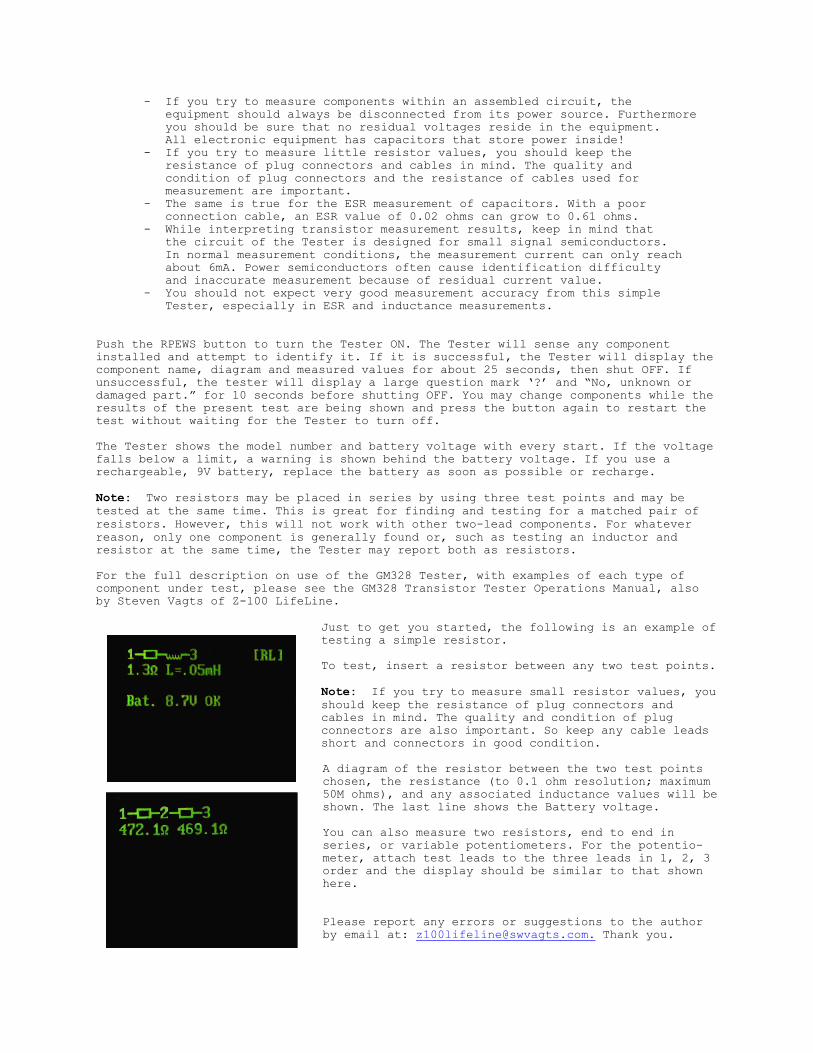
Just to get you started, the following is an example oftesting a simple resistor.
To test, insert a resistor between any two test points.
Note: If you try to measure small resistor values, youshould keep the resistance of plug connectors andcables in mind. The quality and condition of plugconnectors are also important. So keep any cable leadsshort and connectors in good condition.
A diagram of the resistor between the two test pointschosen, the resistance (to 0.1 ohm resolution; maximum50M ohms), and any associated inductance values will beshown. The last line shows the Battery voltage.
You can also measure two resistors, end to end inseries, or variable potentiometers. For the potentio-meter, attach test leads to the three leads in 1, 2, 3order and the display should be similar to that shownhere.
Please report any errors or suggestions to the authorby email at: [email protected]. Thank you.