Embed Size (px)
Citation preview

Glossary of Biomechanical Terms, Concepts, and Units
MARY M. RODGERS and PETER R. CAVANAGH
Key Words: Biomechanics, Vocabulary.
In the last decade, physical therapists have recognized that the field of biomechanics has become an area of study that can contribute significantly to the profession; therefore, it has become a part of most curricula. Biomechanics represents an amalgamation of several different fields including mechanics, physics, engineering, anatomy, physiology, and mathematics. More recently, elements of computer science and electronics have also become integral components. The breadth of knowledge required is therefore substantial, and we are not surprised about the lack of precision concerning terminology in certain areas. A lack of formal background during professional preparation may lead to the misuse of some terms because of the relative infancy of biomechanics. The simultaneous inclusion of biomechanics into the body of knowledge of other fields such as orthopedics, ergonomics, prosthetics, and podiatry have sometimes led to disagreement over basic definitions and concepts, which have developed different meanings in different fields.
For these reasons, we found it appropriate to put in one place a collection of frequently used biomechanical terms that have consistent meanings across the various disciplines. This glossary presents definitions, synonyms, units, and commonly used abbreviations for biomechanical terms.
We consulted many standard works in biomechanics for the collection of these terms. These references are given in the suggested readings so that the flow of the article is not interrupted. The final responsibility for the definitions rests, of course, with us; we have also presented our own opinions on terms that many people consistently use incorrectly or ambiguously.
The definitions have been grouped into the following general sections: kinematics, forces, kinetics, computational methods, muscle mechanics, mechanics of materials, instrumentation, body segment variables, units, index, references, and suggested readings. The following general format has been used for entries:
x.y Definition: Note:
Units:
Synonym:
Item
Where appropriate when a special point is to be made Where appropriate SI—Unit US Customary—Unit Where one or more exist. Terms that should not be used as synonyms are also noted.
Symbol: Where one or more commonly used symbols exist, although symbols are not generally standardized.
SECTION 1 KINEMATICS—The Description of Motion
1.1 Mass The quantity of matter in an object. Mass can be thought of conceptually as the number of atoms in the object that would, of course, remain constant regardless of location or gravitational conditions (eg, earth or moon gravity). Weight, however, would vary under these two conditions. The importance of mass in mechanics is that it represents, in linear terms, the resistance to a change of state (a speeding up or slowing down). Note:
Units:
Symbol:
See discussion of confusion between the pound as a unit of both force and mass in 9.3. SI—kilogram (kg) US Customary—pound mass (Ibm) m (or spell out with first use to avoid confusion with abbreviation for meter if context is not clear)
1.2 Rigid Body
A collection of particles occupying fixed locations with respect to each other. The assumption is that a rigid body will not deform under the action of an applied force however large the force may be. Obviously, this is an approximation in every case because all known materials deform by some amount under the action of a force (See 6.6). Nevertheless, the assumption that segments of the human body are rigid is used in almost every whole body biomechanical analysis that has been published to date (See Section 8).
1.3 Center of Mass
The point on a body that moves in the same way that a particle subject to the same external forces would move. Examples of the location of the center of mass of the human body in two different positions are shown in Figure 1.
1.4 Center of Gravity
The point at which a single force of magnitude mg (the weight of the body or system) should be applied to a rigid body or system to balance exactly the translational and rotational effects of gravitational forces acting on the components of the body or system. In other words, the point at which the weight of the body or system can be considered to act.
Note:
Synonym: Symbol:
The center of mass is not necessanly located in the body as Figure 1 shows. first moment of mass, center of gravity (See 1.4) C of M, COM
Note:
Synonym:
Symbol:
i. For all practical purposes, the center of gravity and the center of mass are coincident, although in strict physical terms, there is an infinitesimal difference between the two. ii. The center of gravity of the human body is not fixed at an anatomical location. Its location varies according to the position of the body segments. center of mass (with limitation above) but not center of pressure (See 2.17). C of G, COG
Ms. Rodgers is a doctoral candidate in Biomechanics, The Pennsylvania State University, College of Health, Physical Education and Recreation, University Park, PA 16802 (USA).
Dr. Cavanagh is Professor of Biomechanics, The Pennsylvania State University.
1886 PHYSICAL THERAPY

1.5 Moment of Inertia
The rotational equivalent of mass in its mechanical effect, that is, the resistance to a change of state (a speeding up or slowing down) during rotation. Intuitively, this would appear to be dependent on the mass of the object and the way the mass is distributed. In fact, the effect of distribution of mass is dominant as the following formula indicates:
I= m.r2 (1) where m = mass and r = distance from axis of rotation. Note:
Units:
Synonym: Symbol:
Unlike mass, for which there is only one value, a new value exists for moment of inertia for each new axis that is chosen. SI—kilogram meter squared (kg . m2) US Customary—slug inch squared (sl . in2) second moment of mass lkk where kk represents the axis about which the moment of inertia is calculated
1.6 Radius of Gyration
An abstract concept sometimes used for the estimation of moment of inertia of body segments. If all the mass in a rigid body were assumed to be concentrated at one point located a distance k from the axis of rotation kk such that m . k2 equals lkk, then the distance k is said to equal the radius of gyration. Because
Symbol: Units
m.k2 = lkk
k = SQRT(lkk/m)
k same as units of displacement
(2) (3)
1.7
Motion in Note:
Synonym:
Linear Motion
which all parts of the body travel along parallel paths. This does not imply motion in a straight line that is known as rectilinear translation. Linear motion along a curved path (curvilinear translation) is possible as long as the body does not rotate. translation
1.8 Angular Motion
Motion that is not linear. If the axis of rotation is fixed, all particles in the body travel in a circular manner. If the axis of rotation is not fixed, the motion is actually a combination of translation and rotation. Note:
Units:
The motion of many limb segments is assumed to occur about fixed axes, although the joint centers do in fact migrate. SI—radians (rad, do not abbreviate if context is not clear) US Customary—degrees (°) (deg), revolution (rev)
1.9 Scalar
A quantity that only has magnitude. For example, mass, length, or kinetic energy are scalar quantities and can be manipulated with conventional arithmetic.
1.10 Vector A quantity that has both direction and magnitude. A force, for example, is always described by how big it is and by the direction in which it is acting. Velocity is also a vector quantity because it expresses the rate of change of position in a given direction. Note: When performing calculations with vectors, or
dinary arithmetic will give the wrong answers; therefore, vector addition and other types of vector algebra must be used. For example, the net effect of forces of 50 and 100 N acting at 90 degrees to each other is actually 111.8 N acting at 63 degrees to the 50 N vector (Fig. 2). In
Fig. 1. The location of the whole body center of mass (indicated by the circled cross) in two different postures A. center of mass is inside the body and B. center of mass is outside the body.
Symbol:
equations of motion, a vector quantity will always contribute two unknowns—one for magnitude and one for direction.
a, a, a, a
1.11 Displacement
The change in the position of a body. This change may be translations, whereby every point of the body is displaced along parallel lines; it may be rotational, with the points of the body describing concentric circles around an axis; or it may be a combination of the two. For example, although the general movement of the human body during locomotion is translations, the limbs act with rotatory motion around manv joints to obtain this end result. Units:
Symbol:
SI—linear: meters (m); rotational: radians US Customary—linear—feet (ft), rotational—degrees (°) (deg) or revolutions (rev) x or s
1.12 Velocity
A measure of a body's motion in a given direction. Because velocity has both magnitude and direction, it is a vector quantity that can be positive, negative, or zero. Linear velocity is the rate at which a body moves in a straight line. Mathematically, velocity is the first derivative with respect to time of displacement (See 4.4) and the first integral with respect to time of acceleration (See 4.6). Note:
Units:
Synonym:
Symbol:
i. The velocity is dependent on which reference frame is used in the computation (See 4.8). For example, the calculation of relative velocity of one body with respect to another uses reference frames that move with both bodies. ii. Because velocity is a vector quantity, it can be expressed as components in any direction, such as horizontally and vertically. SI—meters/second (m/s) US Customary—feet/second (ft/sec or ft/s) miles per hour (mph) Speed and velocity are not synonyms. Speed is a scalar quantity that designates rate and not direction. V
1.13 Angular Velocity
The rate of movement in rotation calculated as the first time derivative of angular displacement. Note: Like linear velocity, angular velocity can be ex
pressed in terms of components along the axes of a coordinate system.
Volume 64 / Number 12, December 1984 1887
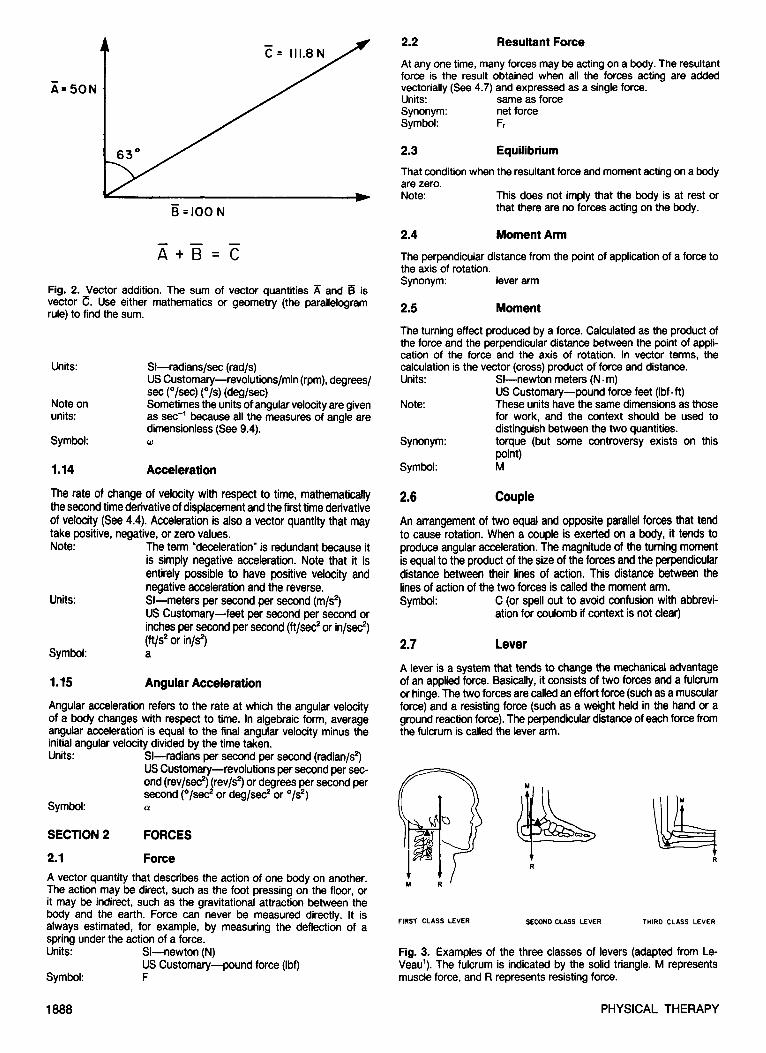
Fig. 2. Vector addition. The sum of vector quantities A and is vector . Use either mathematics or geometry (the parallelogram rule) to find the sum.
Units:
Note on units:
Symbol:
SI—radians/sec (rad/s) US Customary—revolutions/min (rpm), degrees/ sec (°/sec) (°/s) (deg/sec) Sometimes the units of angular velocity are given as sec"1 because all the measures of angle are dimensionless (See 9.4). ω
1.14 Acceleration
The rate of change of velocity with respect to time, mathematically the second time derivative of displacement and the first time derivative of velocity (See 4.4). Acceleration is also a vector quantity that may take positive, negative, or zero values. Note:
Units:
Symbol:
The term "deceleration" is redundant because it is simply negative acceleration. Note that it is entirely possible to have positive velocity and negative acceleration and the reverse. SI—meters per second per second (m/s2) US Customary—feet per second per second or inches per second per second (ft/sec2 or in/sec2) (ft/s2 or in/s2) a
1.15 Angular Acceleration
Angular acceleration refers to the rate at which the angular velocity of a body changes with respect to time. In algebraic form, average angular acceleration is equal to the final angular velocity minus the initial angular velocity divided by the time taken. Units:
Symbol:
SI—radians per second per second (radian/s2) US Customary—revolutions per second per second (rev/sec2) (rev/s2) or degrees per second per second (°/sec2 or deg/sec2 or °/s2) α
SECTION 2 FORCES
2.1 Force A vector quantity that describes the action of one body on another. The action may be direct, such as the foot pressing on the floor, or it may be indirect, such as the gravitational attraction between the body and the earth. Force can never be measured directly. It is always estimated, for example, by measuring the deflection of a spring under the action of a force. Units:
Symbol:
Sl—newton (N) US Customary—pound force (Ibf) F
2.2 Resultant Force
At any one time, many forces may be acting on a body. The resultant force is the result obtained when all the forces acting are added vectoriallv (See 4.7) and expressed as a sinale force. Units: Synonym: Symbol:
same as force net force Fr
2.3 That condition
Equilibrium
when the resultant force and moment acting on a body are zero. Note: This does not imply that the body is at rest or
that there are no forces acting on the body.
2.4 Moment Arm
The perpendicular distance from the point of application of a force to the axis of rotation. Synonym: lever arm
2.5 Moment
The turning effect produced by a force. Calculated as the product of the force and the perpendicular distance between the point of application of the force and the axis of rotation. In vector terms, the calculation is the vector (cross) product of force and distance. Units:
Note:
Synonym:
Symbol:
SI—newton meters (N • m) US Customary—pound force feet (Ibf • ft) These units have the same dimensions as those for work, and the context should be used to distinguish between the two quantities. torque (but some controversy exists on this point) M
2.6 Couple
An arrangement of two equal and opposite parallel forces that tend to cause rotation. When a couple is exerted on a body, it tends to produce angular acceleration. The magnitude of the turning moment is equal to the product of the size of the forces and the perpendicular distance between their lines of action. This distance between the lines of action of the two forces is called the moment arm. Symbol: C (or spell out to avoid confusion with abbrevi
ation for coulomb if context is not clear)
2.7 Lever
A lever is a system that tends to change the mechanical advantage of an applied force. Basically, it consists of two forces and a fulcrum or hinge. The two forces are called an effort force (such as a muscular force) and a resisting force (such as a weight held in the hand or a ground reaction force). The perpendicular distance of each force from the fulcrum is called the lever arm.
Fig. 3. Examples of the three classes of levers (adapted from Le-Veau1). The fulcrum is indicated by the solid triangle. M represents muscle force, and R represents resisting force.
1888 PHYSICAL THERAPY

The functions of a lever are twofold. First, a lever can serve to increase the effect produced when a force is exerted. Secondly, a lever can lengthen the distance over which the force acts and thereby increase the speed of the movement. Examples of the dominance of both of these functions are readily available in the musculoskeletal system (Fig. 3).1
The exact function in a particular case is dependent on the length of the lever arms of the two forces. The following three classes of levers have been identified on this basis: Class of Lever First Class Second Class
Third Class
Location of Effort Force and Resisting Force On opposite sides of the fulcrum On the same side of the fulcrum with resistance arm closer to the fulcrum On the same side of the fulcrum with effort force closer to the fulcrum
This is an arbitrary, nonfunctional classification. The importance of a lever system is its function, not its structure.
2.8 Mechanical Advantage
The mechanical advantage of a lever system is the ratio of the effort-force lever arm to the resisting-force lever arm. A ratio of 1 indicates no change in mechanical advantage, less than 1 a decrease, and greater than 1 an increase in mechanical advantage. A first-class lever can therefore have any value for mechanical advantage, a second-class lever always has a value greater than 1, and a third-class lever always has a value less than 1. Symbol: MA
2.9 Weight
The force that results from the action of a gravitational field on a mass. Weight can be thought of as the force an object exerts on a stationary supporting surface placed perpendicular to a gravitational field (and by Newton's third law as the force the surface exerts on the object). Note:
Units: Synonym:
Symbol:
When we "weigh" ourselves, we are determining weight not mass, but as long as the gravitational field is the same (the acceleration resulting from gravity does not change), mass can be estimated from weight using Newton's second law. same as force none (especially not mass) but weight is equal to the ground reaction force when the object is at rest on a horizontal surface W (or spell out to avoid confusion with abbreviation for work or watt if context is not clear)
2.10 Friction
The tangential force acting between two bodies in contact that opposes motion or impending motion. If the two bodies are at rest, then the frictional forces are called static friction. If there is relative motion between the two bodies, then the forces acting between the surfaces are called kinetic friction. Two types of friction exist: dry friction, also called coulomb friction, and fluid friction. Most biome-chanical analyses involve dry friqtion. The maximum force of static friction between any pair of dry unlubricated surfaces follows two laws: 1) it is independent of the contact area, and 2) it is proportional to the normal force. The normal force is exerted by either body on the other, perpendicular to their mutual interface. The ratio of the magnitude of static friction to the magnitude of the normal force is called the coefficient of static friction and shows the following relationship: f = µs N, where f = friction, µs = coefficient of static friction, and N (in this case) = magnitude of the normal force. Units: Symbol:
same as force f for the frictional force and µs for the coefficient of friction.
2.11 Joint Forces
The forces that exist between the articular surfaces of the joint. Joint forces are the result of muscle forces, gravity, and inertial forces (usually, muscle forces are responsible for the largest part).2
Units: Synonym:
same as rorce bone on bone forces but not joint reaction forces
2.12 Joint Reaction Forces
The equal and opposite forces that exist between adjacent bones at a joint caused by the weight and inertial forces of the two segments. Joint reaction force is a fairly abstract concept useful in mathematical analysis but not much use in practice. This quantity must not be confused with joint forces that include the effects of muscle action.2
Units: Synonym:
same as force none but not joint forces or bone on bone forces
2.13 Ground Reaction Forces
The forces that act on the body as a result of interaction with the ground.3 Newton's third law implies that ground reaction forces are equal and opposite to those that the body is applying to the ground. Ground reaction forces can be measured with a force platform. Notes: i. The conventions usually adopted are those
shown in Figure 4, where positive forces act in the following manner: Fx Horizontally tending to push the foot laterally. Fy Horizontally tending to push the foot backwards. Fz Vertically upwards. ii. The above three directions do not constitute a right-handed Cartesian system (See 4.14). This is because the forces were originally defined not as ground reaction forces but as forces applied to the platform that are, by Newton's third law, equal and opposite to the ground reaction
GROUND REACTION FORCES
FORCES APPLIED TO THE GROUND
Fig. 4. Usual conventions for the effect of ground reaction forces on the body: positive Fx—lateral (to both feet), positive Fy—backwards, positive Fz—upward.
Volume 64 / Number 12, December 1984 1889

Fig. 5. The meaning of center of pressure (C of P). A theoretical distribution of pressure during standing (A). When pressure exists under both the heel and ball of the foot, the C of P will be in the midfoot region, which in itself is not bearing much pressure. During walking, the C of P can be plotted as it moves under the foot (B).
forces. This system is also shown in Figure 4. The choice to use either ground reaction forces or forces applied to the platform is a fundamental one that must be made depending on the particular study.
Units: same as force
2.14 Inertial Forces
The product of the mass of a body and its acceleration or the moment of inertia and the angular acceleration. Note:
Synonym:
A system of drawing free body diagrams referred to as D'Alembert's theorem involves adding in-ertial forces to the free body diagram. This method is not recommended. inertia forces
2.15 Gravitational Force
The force exerted on an object as a result of gravitational pull. This force may be considered as a single force representing the sum of all the individual weights within the object.
2.16 g
The symbol used to represent the acceleration because of gravity on earth. Although this quantity actually varies according to location and
altitude, the usual value used is 9.81 m/sec2 (or 32.2 ft/sec2), which is the value measured in Paris, France. Note:
Units:
Synonym:
Symbol:
The symbol is sometimes used incorrectly as a synonym for acceleration. SI—meters per second squared (m/s2) US Customary—feet per second squared (ft/ sec2) (ft/s2) not G (which stands for the Universal Constant of Gravitation) g
2.17 Center of Pressure
A quantity available from a force platform describing the centroid of the pressure distribution (Fig. 5).3 It can be thought of as (and is sometimes called) the point of application of the force, but this is a somewhat misleading definition unless the force is truly applied at a point (eg, by the tip of a walking cane). In the more general case, the force is applied over a diffuse area (eg, the plantar aspect of the foot). Units:
Synonym: Symbols:
SI—meters (m) (or relative units—eg, % of foot length from heel origin) US Customary—feet (ft) point of force application, force line origin The x, y coordinates are sometimes referred to as CPX, CPY in the ground reaction force reference frame shown in Figure 4.
2.18 Force Line
A line representing the resultant ground reaction force vector drawn starting at the center of pressure and with magnitude and direction determined by the measured components of the ground reaction force vector (See 2.13 and 2.17). This presentation has become more relevant recently because hardware devices are available to combine force platform and video outputs to display the force line immediately after a patient has been examined.4
Note:
Units:
See 2.17, limitations on the meaning of the center of pressure, which is where the force line originates. If the video display has both sagittal and frontal views, the force line presentation contains five distinct pieces of information and, therefore, the units need a scale for each that should appear on the display. CPX—center of pressure X coordinate—meters (or % shoe or foot length) CPY—center of pressure Y coordinate—meters (or % shoe or foot length) Fz—vertical component of GRF—N (newtons) Fy—anteroposterior component of GRF—N (newtons) Fx—mediolateral component of GRF—N (new-tons) A sagittal view will contain only Fy, Fz, and CPY.
SECTION 3 KINETICS—The Study of the Forces that Cause Motion
3.1 Newton's Laws
Three laws that form the basis of conventional or Newtonian Mechanics. The laws can be remembered by the acronym IN-MO-RE: 1) first law of INertia, 2) second law of Momentum, and 3) third law of REaction.
Newton's first law states that a body will maintain a state of rest or uniform motion unless acted on by a net force.
Newton's second law states that the change in momentum of the body under the action of a resultant force will be proportional to the product of the magnitude of the force and the time for which it acts (ie, the impulse). The second law also states that the change in momentum will be in the direction of the resultant force.
Newton's third law states that action and reaction are equal and opposite. Although the first and third laws are somewhat intuitive, the second law provides a means for 1) the formulation of equations
1890 PHYSICAL THERAPY

of motion (See 4.11), 2) the definition of units of force (See Section 9), and 3) the formulation of the impulse momentum relationship (See 3.5). The second law is frequently stated as, "Force equals mass times acceleration" (F = m ∙ a). This is derived from the formal statement of the law using the following symbols:
v1 = initial velocity (before force starts to act) v2 = final velocity (after force has acted) m = mass of object F = magnitude of a constant force t = time for which force acts a = average acceleration
Change in momentum = mv2 - mv1 (4)
impulse = force x time = F t (5)
therefore,
F-t = mv2 - mv1 (6)
then,
F = m(v2 - v1)/t (7)
but,
(v2 - v1/t = acceleration. (8)
Therefore,
F = m a (9) Thus, the second law can be restated as, "The force acting on a body is equal to the mass of the body multiplied by its acceleration." The definition of units of force follows directly from this statement of the law (See Section 9).
Change in momentum = mv2 - mv1 (4) impulse = force x time = F t (5)
therefore,
F ∙ t = mv2 - mv1 (6) then,
F = m(v2 - v1)/t (7) but,
(v2 - v1)/t = acceleration. (8) Therefore,
F = m ∙ a (9) Thus, the second law can be restated as, "The force acting on a body is equal to the mass of the body multiplied by its acceleration." The definition of units of force follows directly from this statement of the law (See Section 9).
3.2 Impulse
The effect of a force acting over a period of time. Impulse is determined mathematically by the integral of the force-time curve, more simply thought of as the area under the force-time curve. Newton's second law allows us to quantify the effect of a force on the velocity of an object if we know the impulse by the impulse momentum relationship. Units: SI—newton seconds that reduce to kg • m/s (N •s)
US Customary—pound force seconds (Ibf-s) (Ibf-sec)
Units: SI—newton seconds that reduce to kg-m/s (N∙ s) US Customary—pound force seconds (Ibf∙s) (Ibf∙sec)
3.3 Linear Momentum
The product of the mass of an object and its linear velocity. Note: The units are the same as those for impulse as
Units:
is necessary for the impulse-momentum relationship to be dimensionally homogeneous (See 9.4). SI—kilogram meters per sec (kgm/s) US Customary—foot pounds per sec (lb-ft/sec) (lb ft/s)
3.4 Angular Momentum
The rotational equivalent of linear momentum that can be thought of as describing the "amount of motion" that the body possesses during rotation. Computationally, it is the product of the moment of inertia and the anqular velocity (angular momentum = lkk). Note:
Units:
Symbol:
Because angular momentum is a vector quantity, it can be resolved into components. It is possible to have angular momentum about one axis and none about another. Angular momentum can, however, be transferred from one axis to another. SI—kilogram meters squared per sec (kgm2/s) US Customary—pound feet squared per sec (lb-tf2/sec)(lb•tf2/s) H (or spell out to avoid confusion with abbreviation for henry if context is not clear)
3.5 Impulse-Momentum Relationship
The change in momentum experienced by a body under the action of a force is equal to the impulse of the resultant force. This follows directly from the definition of Newton's second law (See 3.1).
3.6 Work
Work is done when a force moves an object through a distance. Whenever a constant force exists and motion takes place in a straight line, then work equals the magnitude of the force (F) times the distance (d) through which the object moves: W = F.d. If the force is not constant, work equals the integral (See 4.6) of force with respect to distance:
Notes:
Unit:
Symbol:
W = ∫ F dx (10) i. According to this definition, no mechanical work is done during isometric action of a muscle. An ongoing debate about the implications of this exists because any muscle action clearly involves the expenditure of metabolic energy. ii. The definition of work is independent of time. Thus, the same amount of work is done in raising a 20 kg weight overhead slowly or quickly. The power in these situations is not, however, the same (See 3.7). SI—joule (J) US Customary—foot pound (ft. Ibf) W (which is also the abbreviation for the SI unit of power—the watt in and for weight)
3.7 Power
The rate of doing work. Power is equal to the work done divided by the time during which the work is being done: P = W/t. More strictly, this definition is "average power" because it is possible to calculate the "instantaneous power" by taking the derivative (See 4.4) of work as a function of time: P = dW/dt. Unit:
Synonym:
Symbol:
SI—watt (W) US Customary—horsepower (hp) or foot pound per second (ft. lb/sec) Work rate (but this is colloquial and should not be used) P
3.8 Energy
The capacity for doing work. In any system, this capacity cannot be destroyed, but energy can be transformed from one form to another (this is a statement of the Principle of Conservation of Energy).
In biomechanics, the forms of energy that are most frequently encountered are kinetic energy (See 3.9), potential energy (See 3.10), strain energy (See 6.11), and heat energy. Note:
Units:
Symbol: Synonym:
The units of work and energy are the same because of the relationship of these two quantities through the work-energy principle (See 3.11). SI—joule (J) US Customary—foot pound (ft.lb) E Although work and energy are closely related, they should not be used synonymously. The context should be used to determine the correct usage.
3.9 Kinetic Energy
That component of the mechanical energy of a body resulting from its motion. Two forms of kinetic energy are identified.
Kinetic energy of translation = ½m∙v2 (11) Kinetic energy of translation = ½m∙v2 (11) Kinetic energy of rotation = ½|kk∙w2 (12)
Units: (See 3.8)
Volume 64 / Number 12, December 1984 1891

Symbol: T, however, KE is more commonly used TKE is used for translational kinetic energy RKE is used for rotational kinetic energy
3.10 Potential Energy
That component of the mechanical energy of a body resulting from its position.
Potential Energy = m.g.h (13) where m is mass, g is acceleration resulting from gravity, and h is distance above datum Units: Note:
Symbol:
(See 3.8) Potential energy is always calculated according to an arbitrary reference point or datum and can therefore assume any value depending on the choice of the datum. This is not as impractical as it seems because it is frequently the change in potential energy that is important and this is independent of the choice of a datum (See 3.11). V, however, PE is more commonly used (V is also used as an abbreviation for volt)
3.11 Work—Energy Principle
The work done on a body is equal to the change in kinetic energy of the body. A more comprehensive statement is that the work done on the body is equal to the change in the energy level of the body. Note: If the change in Etot is positive, then work has
been done on the body—positive work. If the change in Etot is negative, then the body has done work on some other body—negative work.
3.12 Energy Level
The total mechanical energy of a body or system. This total represents the sum of the translational and rotational kinetic energy and the potential energy.
Energy level = KET + KER + PE (14) Etot = (½m.v2) + (½lkk.ω2) + (m.g.h) (15)
Note:
Units: Synonym: Symbol:
Some published work has attempted to equate the changes in energy levels of all segments of the body with the expenditure of metabolic energy. Although these quantities are dimen-sionally homogeneous (See 9.4), a number of biological reasons exist why this relationship is inexact (See 5.10). (See 3.8) total mechanical energy E t o t
SECTION 4 COMPUTATIONAL METHODS
4.1 Composition of Vectors The use of vector algebra to combine vectors that act in the same plane (coplanar) and that have the same point of application (concur-
Fig. 6. Resolution of vectors using a parallelogram method. The vector can be resolved into two or more components in any chosen directions, such as y and x or a and d.
rent). The use of vector algebra to combine vectors in this way is called composition of vectors. An example of this is shown in Figure 2. Synonym: vector addition
4.2 Resolution of Vectors
The reverse process from vector composition. One approach to writing equations of motion involves the derivation of both horizontal and vertical equations. Because vectors will not, in general, act in either of these directions, one vector is resolved (Fig. 6) using vector algebra into two components that are in the required directions. Synonym: taking components
4.3 Differentiation
A technique of calculus for finding the rate of change of a quantity. This can result in a single value (for the instantaneous rate of change) or a new curve derived from the rate of change at each point. Graphically, the process can be thought of as determining the instantaneous gradient of a curve (the change in the y direction divided by the change in the x direction), assuming conventional Cartesian axes and coordinates (See 4.14). Differentiation can be performed graphically (by drawing tangents to the curve), numerically (by calculating the difference between two adjacent y values divided by the difference between the x values of the same points), or analytically (according to a set of rules for functions such as y = ax2 + bx + c). Note:
Symbol:
i. The quantities do not necessarily vary with time, but they can be functions of any variable (eg, distance). ii. Differentiation of an unsmcothed signal (eg, the output of an electrogoniometer) can produce almost meaningless data because the process is biased in favor of high frequency components that are often present as "noise" in the data (See 4.12). Similar comments apply to differentiation of numerical data collected from film analysis using a digitizer. Therefore, some form of filtering (See 4.13) almost always precedes differentiation. d(a)/db, where a is being differentiated with respect to b. Note that a and b would be on the x-and y-axes of a conventional plot.
4.4 Derivatives
Quantities obtained by the process of differentiating a given curve or function. The most commonly used derivatives are of displacement (x) where first derivatives dx/dt = velocity, second derivative d2 x/dt2
= acceleration, and third derivative d3x/dt3 = jerk. N o t e : A c c e l e r a t i o n is obtained from jerk, velocity from
acceleration, and displacement from velocity by the reverse process (integration).
4.5 Integration
A technique of calculus for determining the area enclosed between a curve and the x-axis. This can result in either a single value or a new curve derived from the varying function. Integration can be performed either graphically, mathematically, or numerically, and it is the inverse process of differentiation. Notes: i. Unlike differentiation, integration tends to be a
smoothing process and, therefore, the curve obtained from integration is smoother than the one from which it was derived. ii. Limits of integration establish where on the x-axis of the curve, the integration is to be started and terminated. iii. Initial conditions are needed to evaluate completely an integral (called a definite integral). Typically, if a body was at rest before a force began to act, the initial condition would be v = 0 at t = 0.
1892 PHYSICAL THERAPY

Symbol: LLUL a db, where a is on the y-axis of a conventional plot, b is on the x-axis of a conventional plot, LL is the lower limit of b at which integration is to be started, and UL is the upper limit of b at which integration is to be ended.
4.6 Integrals
Quantities obtained by the process of integration. In biomechanics some of the most commonly used integrals are velocity = integral of acceleration with respect to time, displacement = integral of velocity with respect to time, and work = integral of power with respect to time.
4.7 Vector Algebra
A set of definitions, rules, and operations used for computational purposes in the manipulation of vector quantities. The two most well-known operations are
vector (or cross) product = A × B = AB cos(0) (16) scalar (or dot) product = A.B = | A | | B | sin(θ) (17)
where A and B are vectors and 6 is the angle between them. The symbol | | means the magnitude (size) of the enclosed quantity regardless of sign. The multiplication of A and B in the vector product involves a multiplication of all the components of the two vectors using matrix algebra. The multiplication of the magnitudes of A and B in the scalar product is conventional multiplication of two numbers. The physical result of the vector product is a third vector mutually perpendicular to A and B (Fig. 7), and the result of a scalar product is a scalar that represents the size of the projection of vector A on vector B (Fig. 8). Resolution and composition of vectors are further examples of vector algebra (See 4.1 and 4.2).
4.8 Reference Frame
An origin and a set of coordinate axes that serve as the basis for the calculation of displacement and its derivatives. Many types of reference frames are frequently used. a. Inertia) reference frames: Reference frames that are fixed relative to the space in which objects are moving. Inertial reference frames are, in general, reference frames fixed in the earth. The term "fixed reference frames" is sometimes used as a synonym, but this is incorrect because all reference frames are fixed to some point even if the point happens to be moving. b. Moving reference frames: Reference frames that are "body fixed" and move with the body being studied. The use of moving reference frames allows the spatial relationships between two objects to be expressed using matrix algebra but also introduces other complications (See 4.14). Symbols: oXY in two dimensions where o is the origin and
X and Y are the rectangular coordinate axes oXYZ in three dimensions where Z is the third axis
4.9 Space Diagrams
A representation of an object in the environment in which it is to be studied. This diagram should include other bodies and surfaces that the object contacts. An example is shown in Figure 9.
4.10 Free Body Diagram
A diagram in which all the forces and torques acting on a body are identified. This includes forces like gravity, frictional forces, and reaction forces caused by contact with other objects. The name originates from the fact that the body is "freed" from its external contacts that are replaced by reaction forces. The drawing of a free body diagram is an essential first step to the solution of problems in statics and dynamics. A free body diagram for the same situation demonstrated in the space diagram of Figure 9 is shown in Figure 10. Symbol: FBD
Fig. 7. The vector product of vectors A and is a vector that is perpendicular to both and is physically represented here as vector .
Fig. 8. The vector . theresult of the scalar product A- .represents the projection of vector A on vector
4.11 Equations of Motion
Equations obtained by using Newton's second law to equate, in the linear case, the resultant force acting on a body with the product of the linear accelerations and the mass. In the angular case, the relationship is between the net moment acting on a body and the product of moment of inertia and angular acceleration. The equations are usually written following the drawing of a free body diagram in which all the forces and moments acting on the body are identified. The equations of motion for the free body diagram given in Figure 10 are shown in Figure 11.
4.12 Noise
Error present in data collected that is unrelated to the process being studied. Some noise is almost always present in data collected in biomechanics and most other fields. Some typical examples are noise caused by human error in digitizing film, electrical interference in EMG, or mechanical vibration in a force platform. Noise may be random or systematic, and different techniques must be used to eliminate different kinds of noise. (See 4.13)
4.13 Smoothing
A class of techniques for reducing the effects of noise. For systematic noise, this usually involves a clear knowledge of the source of the noise (eg, 60 Hz electrical interference). For attenuating the effects of random noise, a variety of techniques are used such as digital or electrical filtering, curve fitting, and averaging. Synonym: filtering and fitting of data (although these are
actually smoothing techniques)
Volume 64 / Number 12, December 1984 1893

Fig. 9. Space diagram of a lower leg during the swing phase of gait.
Fig. 10. Free body diagram of the lower leg in the swing phase of gait, x and y = joint reaction forces; W = segment weight; θ = segment angle; Τ = joint moment; r = distance to segment C of G.
4.14 Cartesian Coordinate System
A system whereby a point can be located in space by three coordinates, usually denoted by (x, y, z), which express the perpendicular distance of the point along the respective axis from an origin. The three axes are mutually perpendicular. The system is said to be right-handed if a rotation from x to y is clockwise and in the direction of positive z. A two-dimensional Cartesian system involves mutually perpendicular x- and y-axes.
SECTION 5 MUSCLE MECHANICS
5.1 Contraction In muscles, an active shortening of the muscle resulting in a reduction in the distance between the two ends of a muscle. It has, however, become popular to use the term to imply development of tension by a muscle whether or not shortening is underway. This usage is inexact and is not encouraged.
5.2 Muscle Action
The development of muscle tension (more appropriate than the term "contraction"). It can be applied to any type of tension development regardless of whether a muscle is lengthening, shortening, or maintaining the same length.
5.3 Eccentric Muscle Action
Muscle lengthening under tension. This lengthening occurs when the external force acting on the segment to which a muscle is attached causes a net moment that is greater than the moment that is being developed by the muscle and its synergists. Note: Use of the term "contraction" is clearly inappropriate for this type of muscle action.
5.4 Concentric Muscle Action
Muscle shortening under tension. This shortening occurs when the net moment developed by a muscle and its synergists is greater than the moment caused by the external forces acting on the segment to which the muscle is attached.
5.5 Isotonic Muscle Action Muscle action that involves the production of a constant force. For in vivo muscle actions, the term is also commonly used both when the joint moment is constant over a range of motion and when a constant load is being moved through a distance. It is important to realize, however, that because of the leverage effects at the joint, the force developed by the muscles in both these cases will actually be changing, rendering them nonisotonic.
5.6 Isometric Muscle Action
Muscle action that involves no change in length of the muscle. This condition probably does not exist because the contractile components of a muscle shorten at the expense of the elastic structures in series even when the joint crossed by the muscle is fixed. The definition, therefore, is usually relaxed to mean the action of a muscle when no change exists in the distance between its points of attachment—referring to the joint and not to the muscle.
5.7 Isokinetic Muscle Action
Muscle action in which the rate of shortening or lengthening of the muscle is constant. Because joint geometry makes this impossible to determine in vivo, the definition is usually relaxed to apply either to a constant velocity of the load being lifted or resisted or to a constant angular velocity of the joint. Note: Both isokinetic and isotonic actions are fairly
artificial when considered in the context of movements that occur in activities of daily living. Muscles usually shorten or lengthen at varying rates and with varying tensions. These actions are, nevertheless, useful for testing muscles under standardized conditions.
1894 PHYSICAL THERAPY

5.8 Origin
The source or beginning of a muscle. The term generally refers to the more fixed end or the more proximal end. Note: This is an ambiguous term for any muscle that
has attachments that are equally mobile or with both attachments in the same transverse plane. Use of the term tends to encourage the mistaken notion that muscles have their only action at the moveable rather than the fixed end. The same tension is, of course, applied to both ends. The term attachment is more appropriate for reference to either end of the muscle.
5.9 Insertion
The more distal attachment of the muscle or the attachment that is more mobile. Again, this is an ambiguous term for which attachment should be substituted (See Note in 5.8).
5.10 Muscular Efficiency
Expresses the ratio of the mechanical work done to the metabolic energy expended (a widely used term in biomechanics and physiology). This definition has many problems, most of which are related to the definition of the work done. The major stumbling blocks to the establishment of a relationship are the storage of elastic energy in muscles, the different metabolic costs of positive and negative work, and the energy transfer between body segments.
5.11 "Spurt" and "Shunt" Muscles
A muscle's ability to exert rotatory force on a limb. This classification has, however, been challenged.5 When the distal attachment is close to the joint at which the muscle acts, the muscle is called a spurt muscle. This is said to result in a greater rotatory component compared with its stabilizing component. The shunt muscles have their more proximal attachment close to the joint, and their action is said to be more for stabilization than for rotation. The biceps brachii muscle is often presented as an example of a spurt muscle and the brachioradialis muscle as an example of a shunt muscle.
5.12 Tension-Length Relationship
The variation in force output of a muscle, with the same neural input, over a range of lengths. The reasons for this variation include a change in the number of possible active sites for cross-bridge formation and the effect of the elastic tissues that are in parallel with the contractile tissue. A typical tension-length curve for human muscle is shown in Figure 12. Note: The moment that the muscle can develop about
a joint will vary both according to the tension-length relationship and as a function of the geometry of the joint (the location of its attachments and so forth). A typical joint angle—maximum moment curve—is shown in Figure 13.
5.13 Force-Velocity Relationship
At any given length, the speed of shortening or lengthening of a muscle that is stimulated at a constant level will depend on the force that is applied to the ends of the muscle. The Hill equation, best known of the force-velocity equations, describes mathematically the fact that light loads can be lifted quickly but heavy loads only slowly.6
Although it is often stated that maximal muscle force is available at zero velocity (isometric action), the highest loads are achieved during eccentric muscle action.
5.14 Muscle Model
Any mechanical or mathematical model that describes the function of muscle tissue during activity and rest. The best known of these is the three-component Hill6 model that postulates a contractile element, a series elastic element, and a parallel elastic element in the configuration seen in Figure 14.
Vertical
Horizontal
Rotational
Figure 11. Equations of motion for the free body diagram shown in Figure 10. Where , ÿ = components of acceleration in x and y directions; ICG = moment of inertia of segment about C of G; = angular acceleration; Rx and Ry = joint reaction forces; W = segment weight; 0 = segment angle; τ = joint moment; r = distance to segment C of G.
Fig. 12. Typical tension-length curve for an intact human muscle. This curve includes both active and passive components.
Volume 64 / Number 12, December 1984 1895

Fig. 13. Illustration of joint angle-maximum moment curve for elbow flexion.
SECTION 6 MECHANICS OF MATERIALS
6.1 Density The mass of matter in a given space, that is, the mass per unit volume. Note:
Units:
Symbol:
Pure water at 0°C has a density of 1.0. Objects with a density greater than 1 will sink in water; those with a density less than 1 will float in water. SI—kilogram per cubic meter (kg/m3) US Customary—pound per cubic foot (lb/ft3) p
6.2 Tension
A loading mode in which collinear forces acting in opposite directions tend to pull an object apart. In general, a tensile force will cause the length of the body to be increased and the width to be narrowed.
6.3 Distraction
The movement of two surfaces away from each other. In joints, distraction refers to a form of dislocation where the two joint surfaces are separated but retain their ligamentous integrity.
6.4 Compression
A loading mode in which collinear forces are acting in opposite directions to push the material together. Compression usually results in a shortening and widening of the material.
6.5 Stress
Force per unit area that develops within a structure in response to externally applied loads. The stress may be tensile or compressive depending on the mode of loading. The stress may also be normal (changing the length in a structure) or shear (changing the angle in a structure). Units:
Synonym: Symbol:
SI—pascal (Pa) US Customary—pound force per square inch (psi) pressure but not strain α
6.6 Strain
Deformation that occurs at a point in a structure under loading. Two basic types of strain exist: normal strain, which is a change in length, and shear strain, which is a change in angle. Normal strain is the ratio
of deformation (lengthening or shortening) to original length. Shear strain is the amount of angular deformation that occurs in a structure. For example, a rectangle drawn on one face of a solid before a shear stress is applied will appear as a parallelogram during the application of a shear stress. Units:
Synonym: Symbol:
Because it is a ratio, strain is dimensionless but it is often expressed as percent strain (ie, the above definition multiplied by 100). Because rigid materials deform by only small amounts, the "pseudo units" of microstrains are often used. One microstrain represents a deformation of one ten-thousandth of 1 percent. elongation €
6.7 Modulus of Elasticity
The ratio of stress to strain at any point in the elastic region of deformation, yielding a value for stiffness. The stiffer the material, the higher the modulus. The moduli in compression and tension are different for most biological materials because they are anisotropic (See 6.13). Synonym: Units:
Note on Units:
Symbol:
Young's modulus, modulus, elastic modulus Because it is the ratio of stress to strain and strain is dimensionless (See 9.4), modulus of elasticity has the units of stress. SI—pascal (Pa) or more often newtons per square centimeter (N/cm2) US Customary—pounds per square inch (psi) Some typical values of the modulus of elasticity are bone: approx 5 GPa (wet human femur in compression) and steel: approx 20 GPa. E
6.8 Elastic Deformation
A strain in a material that is entirely reversible when the stress is released.
6.9 Plastic Deformation A strain in a material that is permanent and will not recover when the stress is released.
6.10 Strain Rate
The speed at which a strain-producing load is applied or the first derivative of strain. Note:
Units:
When data on the mechanical properties of biological tissue are presented, it is important to state the strain rate at which the data were collected. Because most tissue is viscoelastic (see 6.19) the properties will be rate dependent. Most testing machines that stress tissue samples are unable to achieve strain rates that are biologically realistic. All published values on biological materials must be viewed with this limitation in mind. SI—meters/sec (m/s) or original lengths/sec US Customary—inches per second (in/sec) (in/ s)
6.11 Strain Energy
The energy that a material can absorb as a result of the change of shape resulting from applied stress. The work done, stored as strain energy in the material, is the product of the average force (V2P) and the deformation.
U = 1/2(P2.L)/A.E (18) where L = material length, A = material area, and E = modulus of elasticity. Graphically, the area under a load-deformation curve represents the strain energy stored in the material during the application of stress.
1896 PHYSICAL THERAPY

Units:
Synonym: Symbol:
SI—newton meters (N . m) US Customary—foot pound force (ft . lbf) energy stored U
6.12 Isotropic
A material that has no directional structure and exhibits the same mechanical properties when loaded in different directions. For example, in an isotropic material (eg, a sheet of natural rubber), the elastic properties are identical in all directions.
6.13 Anisotropic
A material that has a directional structure and exhibits different mechanical properties when loaded in different directions. For example, because the structure of bone or tendon is different in the transverse and the longitudinal directions, the modulus of elasticity varies according to the direction in which the load is imposed.
6.14 Bending
The result of applying a load to a structure such that it bends about an axis. The structure will be experiencing a combination of tension and compression on opposite surfaces.
6.15 Neutral Axis
The central plane in which the tensile and compressive stresses and strains resulting from bending equal zero.
6.16 Bending Moment
A quantitative measure of the tendency of a force to bend a structure. It is calculated as the product of the applied force and the perpendicular distance from the point of force application to the axis. Units: SI—newton meters (N . m)
US Customary—foot pound force (ft . lbf)
6.17 Bone Remodeling
The ability of the bone to adapt, by changing its size, shape, and structure, to the mechanical demands placed on it. The idea that living bone can functionally adapt to internal stresses and strains was first advanced by Julius Wolff in 1884. Wolff's law states that bone is laid down where needed and resorbed where not needed. The remodeling may be either external (a change in the external shape of the bone) or internal (a change in the porosity, mineral content, and density of bone).
6.18 Fatigue
The failure of a material caused by loading.
6.19 Viscoelasticity
The behavior of materials that exhibit the features of hysteresis (See 6.20), stress relaxation (See 6.21), and creep (See 6.22). Note: Modeling of viscoelastic behavior must include
elements such as dashpots (fluid-filled damping units) that can absorb energy, whereas elastic behavior can be satisfactorily modeled by perfect springs, which return all the energy they store.
6.20 Hysteresis
A phenomenon in which a body, when subjected to cyclic loading, exhibits a stress-strain relationship during the loading process different from that in the unloading process (Fig. 15). Note: When a stress-strain diagram for the cyclic load
ing of a material that shows hysteresis is drawn, the result is sometimes called a hysteresis loop. The maximum width of the loop (along the strain
Series Elastic Component
Contractile Component
Parallel Elastic Component
Fig. 14. Three-component Hill model of muscle.
Units:
axis) divided by the largest value for strain expressed in percent is called the hysteresis. percent (%)
6.21 Stress Relaxation
The phenomenon in which the stress in a sample, which was suddenly strained and then maintained at the final strain, gradually decreases with time.
6.22 Creep
Progressive deformation of soft tissues because of constant loading over an extended period of time. This is typically demonstrated by suddenly stressing a sample and then holding the load constant afterwards. If the sample continues to deform, then it is said to be exhibiting creep.
6.23 Shock Absorption
The progressive damping of an applied force. Damping is a complex, generally nonlinear, phenomenon that exists whenever energy is dissipated. Note: It is important to realize that force cannot be
absorbed. A shock absorbent material acts to change the momentum of an impact over a longer period of time than a nonshock absorbent material.
SECTION 7 INSTRUMENTATION
7.1 Transducer
A measuring device that converts one form of energy into another. An electrical displacement transducer, for example, converts kinetic energy from movement into electrical energy. Synonym: sensor
7.2 Force Platform
An electromechanical device that gives electrical signals proportional to the components of force acting on it. The most common use of a force platform is to measure the reaction forces and center of pressure between the foot and the floor during locomotor activities.
Volume 64 / Number 12, December 1984 1897

Fig. 15. Hysteresis loop for the tissue of the heel pad.
The resultant force is usually resolved into three orthogonal components (See 4.14). Force transducers used in a force platform are usually either strain gauges, which change their electrical resistance with strain or piezoelectric elements, which generate charge when stressed. Synonym: force plate but not pressure plate (because no
estimate of contact area is usually available to compute stress)
7.3 Pressure Platform
A device that consists of a matrix of elements that are small force transducers of known area. If this area is sufficiently small, the force on each element can be considered uniformly distributed and, thus, an estimate of pressure is available. Note: This device gives more information concerning
load distribution than a force platform because the pressures acting on various anatomical regions can be measured rather than just the resultant force acting on, for example, the whole foot.
7.4 Accelerometer
A transducer that measures acceleration. It usually. consists of an inertial mass that exerts a force against an element, such as a beam, whose resulting strain is then measured. Note: Like force, acceleration cannot be directly mea
sured and must be estimated from the effects of a force. A major problem associated with making acceleration measurements on body segments is that the transducer is generally fixed to soft tissues rather than bone. The directional effect of the transducer is also a problem because it is always under the influence of gravity.
7.5 Cyclograph
A device used in the collection of kinematic data. It consists of a disk with a sector that is rotated in front of a camera with an open shutter. The subject moves in front of a black background and an image is registered on the film of the posture of the body each time the sector is opposite the camera lens. The result, with multiple images on a single piece of film, is similar to a stroboscope picture.
7.6 Stroboscopy
Multiple image photography in which the camera shutter is held open for a time exposure, and strobe lighting is used to illuminate the subject at designated intervals. Another approach is to affix tiny lights to important body landmarks and flash them at a predetermined rate. The disadvantages of the technique are that the movement must be performed in the dark, and that if a limb segment moves through the same space on more than one occasion, the result is difficult to interpret.
7.7 High-Speed Cinematography
The most frequently used method of examining human motion. Film is taken at a higher rate than the usual 24 frames per second (fps) and subsequently analyzed frame-by-frame using a digitizer. Traditionally, analyses yielding only the two-dimensional coordinates of body landmarks in a single plane have been performed (See 7.8). Biomechanical studies generally use cameras capable of 500 fps or less although frame rates greater than 5,000,000 fps are possible. Synonym: slow-motion cinematography
7.8 Three-Dimensional Cinematography
A technique in which generally two or more motion picture cameras are used to obtain spatial coordinates of landmarks on the body in three dimensions (x, y, z). A variety of techniques is used, but all of them involve extensive analysis and computation. Synonym: 3D cine
7.9 Digitizer
A device that is capable of acquiring planar coordinates in numerical form. In biomechanics, the most frequent use of a digitizer is to convert the location of body markers on the projected image of a film into numbers that can be processed by a computer. Synonym: graphics tablet, digitizing tablet or table
7.10 ELGON
A potentiometer (variable resistor) that is attached to the body to measure a joint angle. The axis of the potentiometer is aligned with the joint axis and the device gives an output voltage that is proportional to joint angle. Note:
Synonym:
Most potentiometers assume there is a single fixed axis of rotation for the joint—-an assumption that is not generally true. Other problems with electrogoniometry include fixation of the device to the body and possible alteration of the movement because of the attachment. The acronym stands for electrogoniometer.
7.11 Optoelectronic Methods
A new generation of devices for measuring the displacement of body landmarks using optical and electronic methods to produce an immediate or on-line estimate. Note: Because cinematography is such a laborious
process, these methods offer considerable promise, particularly for motion analysis in a clinical environment where turn-around time is important. At present, however, most of these methods cannot approach the accuracy of cinematography.
7.12 Selspot
An optoelectronic technique for measuring displacement in which light from a pulsing infrared light target attached to the body is focused onto a special diode inside a camera. The output from the diode, after suitable processing, yields an estimate of the coordinates of the target. Many such targets can be placed on the body and their locations estimated in rapid sequence.
7.13 POLGON
An optoelectronic device for measuring angular displacement that is composed of an optical projector and a number of receivers attached to the body parts under investigation. The light emitted from the projector is directed at the subject through a rotating polaroid screen. Joint angles are available on-line as functions of time. Synonym: The acronym stands for polarized light goniom
eter.
1898 PHYSICAL THERAPY

7.14 Microcomputer
A computer that has the major arithmetic and logical functions all on one integrated chip called a microprocessor. This chip is the heart of the system around which the various other parts of the computer are arranged. Each major type of microprocessor chip has its own number that identifies both the set of instructions it recognizes and its word length. The Apple II, for example, is built around the 6502 microprocessor chip, and the IBM PC is based on the 68000. Note:
Synonym:
Many new devices that are seen in the clinic or laboratory are now "microprocessor controlled," which means they contain a small dedicated microprocessor With preset instructions that respond to input from the control panel or external inputs. microprocessor
7.15 Minicomputer A computer that is built on a larger scale than a microcomputer so that its processing functions are distributed among several main units. A minicomputer is typically found in a laboratory or clinical environment where it can respond to the needs of a number of users simultaneously. It usually has a variety of peripheral devices for storage and output (eg, disk and tape drives, and line printers), and a fairly complex operating system (see 7.16).
7.16 Hardware The actual machines used in data collection and processing as distinct from the programs or instructions that cause them to operate in a given manner.
7.17 Software
Sets of instructions called programs that cause a computer to execute certain operations. These instructions may be written in a high-level language like BASIC, PASCAL, or FORTRAN, or in a lower-level language such as Assembly Language (the higher the level, the closer to the English language). Some categories of software follow: 1. User programs—programs written by individual users. 2. System programs—programs that control the housekeeping functions of the computer—such as input/output and deciding which user to respond to at a given time. Such programs are often stored in ROM (See 7.18). 3. Application programs—programs that are sold to perform a certain function—perhaps statistics or patient record keeping. Sometimes called canned programs. 4. Word processors—programs that work with words rather than numbers as their basic elements. They allow easy editing of text and the generation of form letters with different inserts.
7.18 Read Only Memory (ROM)
An area of computer memory where programs supplied by the manufacturer are stored semipermanently. This form of memory cannot be overwritten by a user. Synonym: The acronym stands for read only memory.
7.19 Random Access Memory (RAM)
An area of computer memory that is available for user programs, data, and other temporary uses. It can be overwritten continually. Synonym: The acronym stands for random access mem
ory-
7.20 On-Line
A term used for data that can be processed and displayed immediately after collection. The opposite term, off-line, implies a lag between data collection and the availability of the results. On-line data collection and analysis are clearly important in a clinical context where feedback is to be given either to the patient or to those who are treating the patient.
SECTION 8 BODY SEGMENT VARIABLES
8.1 Anthropometry
A branch of biomechanics that deals with the measurement of the dimensions, mass, and mass distribution of the human body and its segments.
8.2 Link System
An assumption underlying most anthropometric models of the body that states the body is composed of a system of rigid links whose ends are connected by smooth pin joints. Pheasant has contrasted the use of this assumption with the analogy that a human limb segment is better characterized as "a series of fluid filled sacks loosely connected to a set of deformable rods."7 To cope with such a characterization in biomechanical calculations of body movement would render most problems insoluble.
8.3 Body Segment Factors
Estimates of the lengths, masses, location of the centers of mass, and moments of inertia of body segments that are required for biomechanical analysis of human motion.
8.4 Cadaveric Techniques The segmentation and measurement of cadavers to determine body segment variables. The value of dissection studies lies in their potential for providing a basis for prediction of segmental variables in living subjects. For example, cadaver studies have shown that the mass of the thigh is approximately 10 percent of total body mass. The scope of inference is, however, limited both by the nature of the samples (less than 50 cadavers have been studied and most were geriatric Caucasian males) and by the assumption that cadaver data can be applied to living subjects.
8.5 Mathematical Models The modeling of segments of the body by geometrical shapes as a method of predicting body segment variables. Segments are usually assumed to be homogeneous right or elliptical cylinders, spheres, ellipsoids of revolution, or frustra of cones. The advantage of these models is that estimates are available for all variables; the major disadvantage is that of oversimplification.
8.6 Regression Equation Techniques
The use of multiple correlation and regression techniques to improve on the prediction of body segment variables from cadaveric data. This generally yields an equation for segmental mass, for example, where factors other than (or in addition to) total body mass are included as predictors. In the best known example of this technique, three equations are available for each variable, each using successively more predictors and resulting in an improved standard error of the estimate.8
SECTION 9 UNITS
9.1 Background to Systems of Units All units systems have in common the fact that units for the three fundamental quantities of mass, length, and time are defined arbitrarily to give what are sometimes called the base units. The units of all other quantities are expressed in terms of these base units to form what are called derived units.
The set of units that is still in current use in everyday life in the United States is the British system based on the pound, the foot, and the second. These units have long been out of favor with the scientific community and have even been abandoned by the British for everyday and scientific use. They have therefore been referred to in this paper by the more appropriate title as US Customary units. The generally accepted system of scientific units is the Systeme International d'Unites (the International System or SI system) that was agreed on in 1960.9,10 The system is based on the kilogram, the
Volume 64 / Number 12, December 1984 1899

meter, and the second. This system is the only one now accepted by most scientific journals and should always be used. Conversion factors between the SI and British units are presented in Section 9.5.
Each unit has a standard abbreviation and care should be taken to use both the correct letter(s) and the correct case (upper or lower). When the units for a derived quantity are written (eg, those compound units formed by multiplication), the abbreviations for the elementary quantities should be written with the product dot separating them (eg, N.m for newton meter).
When the size of a quantity becomes very large or small, it is customary to use powers of 10 (positive or negative) to make the number before the multiplier between 1 and 10 or to use standard prefixes that imply a given multiple of powers of 10. Examples of this would be as follows:
5.32 x 10³ N or 5.32 kN rather than 5320 N (19)
7.13 × 10⁻⁴ sec or 0.713 msec rather than .000713 sec (20) Notice that no space exists between the prefix and the symbol for the unit. The most common of the standard series of prefixes that should be used with their correct abbreviation are in the Table. They progress by multiples of 1,000.
TABLE Unit Prefixes and Abbreviations
Prefix Giga Mega Kilo Centi Milli Micro
Abbreviation G M k c m µ
Multiply By 1,000,000,000
1,000,000 1,000 1/100
1/1,000 1/1,000,000
9.2 Definitions of the Base Units
Mass:
Length:
Time:
The kilogram is a unit of mass and not force. The basis of this unit is the mass of a physical specimen—The International Prototype Kilogram—kept in Paris. A replica of this physical specimen is kept at the National Bureau of Standards, Washington, DC. The SI unit of length is the meter. This was originally defined at the time of the French Revolution as 1 /10,000,000 of the distance between the North Pole and the Equator. Despite the primitive methods of making measurements available at the time, they made a remarkably close approximation. Recently the definition has been standardized using the wavelength of an emission from an isotope of krypton. The original definition of the second was 1/ 86,400th of the mean solar day. The modern definition is, like that of length, based on the atomic properties of a radioactive element, in this case, cesium 133.
9.3 Derived Units
Force:
Note:
Using Newton's second law, the SI unit of force, the newton (N), is defined as that force that gives a mass of 1 kg an acceleration of 1 m per second per second. The confusion in the English system between the pound as a unit of mass and the pound force as a unit of force is not present in the SI system. The pound force (Ibf) is defined as the force under a 1-pound mass when it is stationary on a surface in the earth's gravitational field. For obvious reasons, the pound force is called a
Pressure:
Work:
Energy: Power:
Moment:
Plane Angle:
gravitational unit because its definition using Newton's law can be stated as 1 force unit = 1 mass unit.g (21) In the definition of absolute units (such as the newton), Newton's second law has the form 1 force unit = 1 mass unit.1 acceleration unit
(22) Neither the pound force.nor the analogous metric unit—the kilogram force—should be used. The SI unit of pressure is the pascal (Pa). This is the pressure experienced when a force of 1 newton (N) is distributed over an area of 1-square meter (m2). This unit defines an amount of pressure that is extremely small for most biomechanical studies of gross body movement. For example, the average pressure underneath a size nine foot when a 75-kg (165-lb) person is standing on one leg is approximately 70,000 Pa. Thus, the units of kilopascals (kPa) and mega-pascals (mPa) are frequently used. When a force of 1 newton moves through a distance of 1 meter, 1 joule (J) of work is said to have been done. Same units as work. When 1 joule of work is done in a period of 1 second (sec), the power output is said to be 1 watt (W). The units for moment or torque are newton meters (N . m), that is a force of 1 newton applied at a distance of 1 meter from an axis produces a turning moment or torque of 1 newton meter. This unit must nor be simplified to joules because the joule is not a unit of moment. One radian is the angle subtended between two lines joining the center of a circle with two points on the circumference that are the radius of the circle apart. This unit is dimensionless.
9.4 Dimensions When manipulating quantities with a variety of units (eg, in equations of motion), the concepts of dimensions and dimensional analysis are frequently useful.10 In this approach, quantities are manipulated as combinations of the "base" quantities of mass, length, and time, from which, as stated earlier, most other "derived quantities" can be obtained. The symbols of dimensional analysis are [M], [L], and [T], and units are ignored in favor of these quantities. For example, the derived quantity of force is obtained from the product of mass and acceleration. Acceleration is itself a derived quantity that has dimensions of [L][T]"2. It may help to think of the units that are meters (length) per second (time) per second (time). Thus, the final dimensions of force are [M][L][T]-2.
Dimensional analysis can be extremely useful in finding errors in equations. For example, in calculating the moment of a force about a point, the dimensions of the answer, which is calculated as force multiplied by a distance, will be [M][L]2[PT-2. Suppose, in the calculation of a moment equation, the following result were obtained:
Fx.x-cos θ + Fy.cos θ = M (23)
where Fx and Fy are force components, x is a distance, 0 is an angle, and M is a moment.
Dimensional analysis would reveal the following:
[M][L][T]-2[L] + [M][L][T]-2 = [M][L]2[T]-2 (24)
The equations are said to be "dimensionally inhomogeneous" because all additive terms do not have the same dimensions. Inspection reveals that the distance component in the second term was missed out and when this error is corrected, all terms will have the same dimensions.
1900 PHYSICAL THERAPY

9.5 Mass
Length
Force
Pressure
Work/Energy
Power
Moment
Angle
Conversion Factors
1 kg = 2.240 lb 1 lb = 0.453 kg 1 m = 1.094 yd 1 m = 3.281 ft 1 m = 39.370 in 1 yd = 0.914 m 1 ft = 0.305 m 1 in = 0.0254 m 1 N = 0.225 Ibf 1 Ibf = 4.448 N 1 kgf = 9.81 N 1 kPa = 0.145 psi 1 bar = 100 kPa 1 atm = 101.3 kPa 1 J = 0.737 ft-Ibf 1 J = 0.243 calories 1 ft. Ibf =1.356 J 1 W = 0.737 ft∙Ibf/sec 1 ft∙Ibf/sec = 1.356 W 1 hp = 746 W 1 N∙m = 0.737 ft∙Ibf 1 ft∙Ibf/sec = 1.356 N∙m 1 radian = 57.3° 1° = 0.0174 radians radians = 180° 60 minutes of arc = 1 ° 60 seconds of arc = 1 minute of arc
SECTION 10
TERMS
Acceleration Accelerometer Angular acceleration Angular velocity Angular momentum Angular motion Anisotropic Anthropometry Definitions of the base units Bending Bending moment Body segment variables Body segment factors Bone remodeling Cadaveric techniques Cartesian coordinate system Center of gravity Center of mass Center of pressure Composition of vectors Compression Computational methods Concentric muscle action Contraction Conversion factors Couple Creep Cyclograph Density Derivatives Derived units Differentiation Digitizer Dimensions Displacement Distraction Eccentric muscle action Elastic deformation ELGON Energy Energy level Equations of motion
INDEX TO TERMS
LOCATION
1.14 7.4 1.15 1.13 3.4 1.8 6.13 8.1 9.2 6.14 6.16 Section 8 8.3 6.17 8.4 4.14 1.4 1.3 2.17 4.1 6.4 Section 4 5.4 5.1 9.5 2.6 6.22 7.5 6.1 4.4 9.3 4.3 7.9 9.4 1.11 6.3 5.3 6.8 7.10 3.8 3.12 4.11
Equilibrium Fatigue Force Force line Force platform Force-Velocity relationship Free body diagram Friction g Gravitational force Ground reaction forces Hardware High-speed cinematography Hysteresis Impulse Impulse-Momentum relationship Inertial forces Insertion Instrumentation Integrals Integration Isokinetic muscle action Isometric muscle action Isotonic muscle action Isotropic Joint forces Joint reaction forces Kinematics Kinetic energy Kinetics Lever Linear momentum Linear motion Link system Mass Mathematical models Mechanical advantage Mechanics of materials Microcomputer Minicomputer Modulus of elasticity Moment Moment arm Moment of inertia Muscle action Muscle mechanics Muscle model Muscular efficiency Neutral axis Newton's laws Noise On-line Optoelectronic methods Origin Plastic deformation POLGON Potential energy Power Pressure platform Radius of gyration Random access memory Reference frame Regression equation techniques Resolution of vectors Resultant force Rigid body Read only memory Scalar Selspot Shock absorption Smoothing Software Space diagrams Spurt and shunt muscles Strain Strain energy
2.3 6.18 2.1 2.18 7.2 5.13 4.10 2.10 2.16 2.15 2.13 7.16 7.7 6.20 3.2 3.5 2.14 5.9 Section 7 4.6 4.5 5.7 5.6 5.5 6.12 2.11 2.12 Section 1 3.9 Section 3 2.7 3.3 1.7 8.2 1.1 8.5 2.8 Section 6 7.14 7.15 6.7 2.5 2.4 1.5 5.2 Section 5 5.14 5.10 6.15 3.1 4.12 7.20 7.11 5.8 6.9 7.13 3.10 3.7 7.3 1.6 7.19 4.8 8.6 4.2 2.2 1.2 7.18 1.9 7.12 6.23 4.13 7.17 4.9 5.11 6.6 6.11
Volume 64 / Number 12, December 1984. 1901

Strain rate Stress Stress relaxation Stroboscopy Tension Tension-Length relationship Three-dimensional cinematography Transducer Units Vector Vector algebra Velocity Viscoelasticity Weight Work Work-Energy principle
6.10 6.5 6.21 7.6 6.2 5.12 7.8 7.1 Section 9 1.10 4.7 1.12 6.19 2.9 3.6 3.11
REFERENCES
1. LeVeau BF: Williams and Lissner: Biomechanics of Human Motion ed 2. Philadelphia, PA, WB Saunders Co, 1977
2. Winter DA: Biomechanics of Human Movement. New York, NY, John Wiley &Sonslnc, 1979
3. Cavanagh PR, Lafortune MA: Ground reaction forces in distance running. J Biomech, 13:397-406, 1980
4. Cook TM, Cozzens BA, Kenosian H: Real-time force line visualization: Bioengineering applications. In: Advances in Bioengineering. New York, NY, American Society of Mechanical Engineers, 1977, p 67
5. Stern JT: Investigations concerning the theory of "spurt" and "shunt" muscles. J Biomech 4:437-453, 1971
6. Aidley DJ: The Physiology of Excitable Cells, ed 2. Cambridge, England, Cambridge University, 1982
7. Pheasant S: Newtonian anthropometry. London, England, Royal Free Hospital School of Medicine, Biomechanics Laboratory, Bulletin 1, September 1976
8. Clauser CE, McConville JT, Young JW: Weight, Volume, and Center of Mass of Segments of the Human Body. Wright-Patterson Air Force Base, OH, publication No. AMRL-TR-69-70, 1979
9. Massey BS: Units, Dimensional Analysis and Physical Similarity. London, England, Van Nostrand, 1971
10. ASTM Standard for Metric Practice. Philadelphia, PA, American Society for Testing and Materials, publication No. E 380-79, 1979
SUGGESTED READINGS
Beer FP, Johnston ER: Vector Mechanics for Engineers—Statics and Dynamics, ed 3. New York, NY, McGraw-Hill Inc. 1977
Chow WM, Sippl CJ: Computer Glossary for Engineers and Scientists. New York, NY, Funk & Wagnalls Inc, 1972
Doriand's Illustrated Medical Dictionary, ed 25. Philadelphia, PA, WB Saunders Co, 1974
Frankel VH, Burstein AH: Orthopaedic Biomechanics—the Application of Engineering to the Musculoskeletal System. Philadelphia, PA, Lea & Febiger, 1970
Frankel VH, Nordin M (eds): Basic Biomechanics of the Skeletal System. Philadelphia, PA, Lea & Febiger, 1980
Frost HM: An Introduction to Biomechanics. Springfield, IL, Charles C Thomas, Publisher, 1967
Fung YC: Biomechanics: Mechanical Properties of Living Tissues. New York, NY, Springer-Verlag New York Inc, 1981
Halliday D, Resnick R: Physics—Parts 1 and 2, combined ed 3. New York, NY, John Wiley & Sons Inc, 1978
Hay JG: The Biomechanics of Sports Techniques, ed 2. Englewcod Cliffs, NJ, Prentice-Hall Inc, 1978
Miller Dl, Nelson RC: Biomechanics of Sport. Philadelphia, PA, Lea & Febiger, 1976
Shames IH: Engineering Mechanics, ed 2. Englewood Cliffs, NJ, Prentice-Hall Inc, 1966
Singer FL, Pytel A: Strength of Materials, ed 3. New York, NY, Harper & Row, Publishers Inc, 1980
Suh NP, Turner APL: Elements of the Mechanical Behavior of Solids. New York, NY, McGraw-Hill Inc, 1975
Taber's Cyclopedic Medical Dictionary, ed 11. Philadelphia, PA, FA Davis Co, 1970
Timoshenko SP, Gere JM: Mechanics of Materials. New York, NY, Van Nostrand Reinhold Company Inc, 1972
Tricker RAR, Tricker BJK: The Science of Movement. New York, NY, Elsevier Science Publishing Co Inc, 1967
Units, Terms and Standards in the Reporting of EMG Research. Montreal, Quebec, Canada, Ad Hoc Committee of the International Society of Electrophysiological Kinesiology, Department of Medical Research, Rehabilitation Institute of Montreal, August 1980
1902 PHYSICAL THERAPY