Embed Size (px)
Citation preview

Global Series ™Air Cylinders
CATALOG GC-150910

Page 2
Global Series™Cylinders
Load Capacity (psi) Machine Design 1972/73 Bearing Reference IssuePorous Bronze .............. 4,500Porous iron .................. 8,000Phenolics ..................... 6,000Nylon® ........................ 1,000TFE .............................. 500Reinforced Telfon® ..... 2,500*TFE fabric .................. 60,000Polycarbonate ............. 1,000Acetal .......................... 1,000Carbon-graphite .......... 600
* Shows Duralon bearing classification. Not to be used for design purposes.
Friction Properties Slip- Coefficient stickSteel-on-steel ......................... .50 YesBronze-on-steel ...................... .35 YesSintered Bronze-on-steel with mineral oil .............. .13 NoBronze-on-steel with mineral oil ............... .16 NoCopper lead alloy-on-steel ..... .22 YesAcetal-on-steel ...................... .20 NoNylon-on-steel ....................... .32 YesDuralon-on-steel .................... .05 - .16 No
Duralon® Rod Bearings Excel
Printed with permission by Rexnord Corp.
NOW LOOK AT ALL
YOU GET
NOW LOOK AT ALL
YOU GET
Extra Long Piston Rod Bearing – The better the bearing is, the more cycle life you can expect from your cylinders. And Global Series™ Cylinders incorporate a truly superior rod bearing material – Duralon® with the same fi eld-proven performance you have come to expect from the fi ve other Fabco-Air cylinder families.
Duralon® is a composite of a Tefl on®/Dacron fabric liner bonded to a supporting fi lament-wound, high strength, fi berglass and epoxy resin shell. Resistant to corrosion, moisture and temperature to 325°, Duralon is reliable in any environment. It has an extremely high load bearing capacity, very low friction, and will not gall or score the piston rod (See physical properties in the above table).
Here is FABCO-AIR's Expanded Line of Space Saving Air Cylinders Innovation – For 40 years our famous Pancakes® have dominated as the world's fi rst compact air cylinder line. Today, backed by decades of engineering innovation, our new Global Series™ extruded body cylinders continue in the Pancake® tradition with exceptional performance and the widest available selection of models and options.
Packed with Value – Tough, rigid, hard anodized alu-minum extrusions house oversized hard chrome stainless steel piston rods for service to 10 bar (150 psi). Magnetic piston position sensing enables mid-stroke signaling and exact end-of-stroke sensing. Multiple dovetails each ac-commodate multiple switches without the need for switch mounting brackets.
Providing Unmatched
9-22-04
Page 3
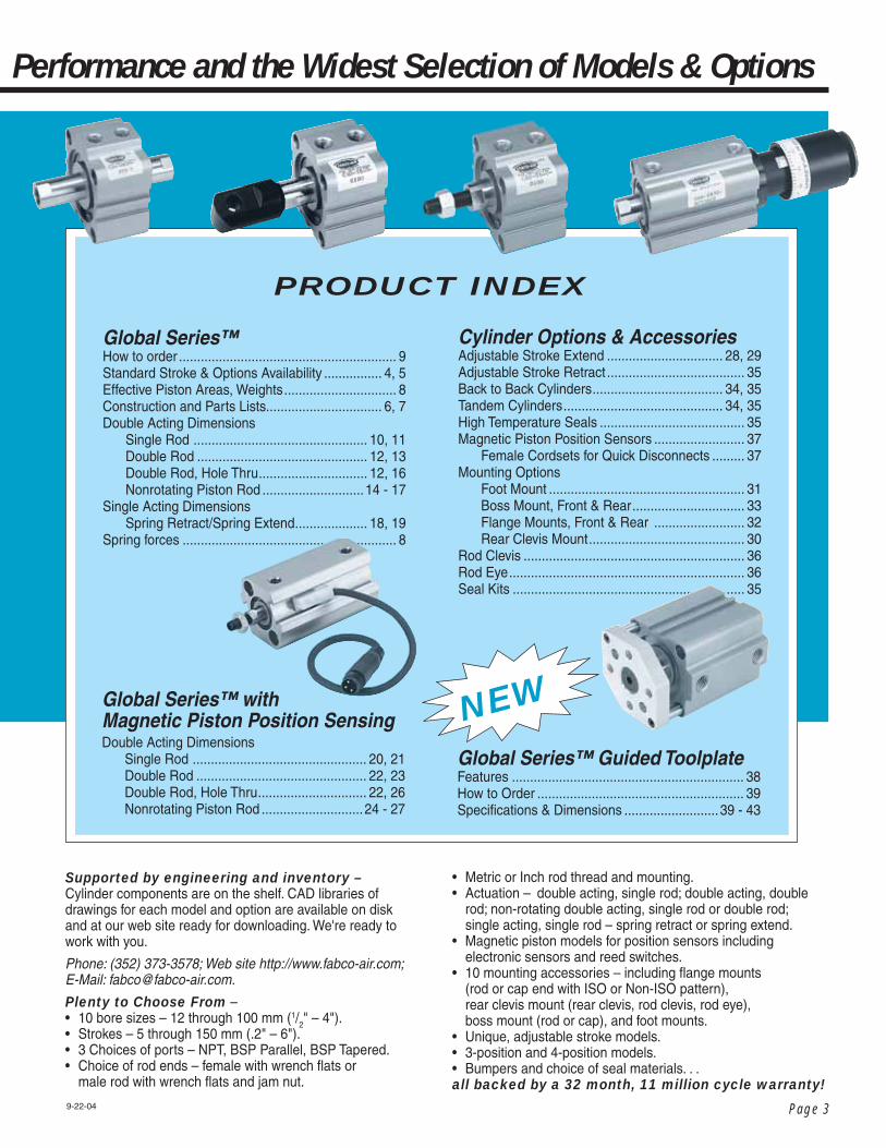
PRODUCT INDEX
Supported by engineering and inventory – Cylinder components are on the shelf. CAD libraries of drawings for each model and option are available on disk and at our web site ready for downloading. We're ready to work with you.
Phone: (352) 373-3578; Web site http://www.fabco-air.com; E-Mail: [email protected].
Plenty to Choose From – • 10 bore sizes – 12 through 100 mm (1/2" – 4").• Strokes – 5 through 150 mm (.2" – 6").• 3 Choices of ports – NPT, BSP Parallel, BSP Tapered.• Choice of rod ends – female with wrench fl ats or male rod with wrench fl ats and jam nut.
• Metric or Inch rod thread and mounting.• Actuation – double acting, single rod; double acting, double rod; non-rotating double acting, single rod or double rod; single acting, single rod – spring retract or spring extend.• Magnetic piston models for position sensors including electronic sensors and reed switches.• 10 mounting accessories – including fl ange mounts (rod or cap end with ISO or Non-ISO pattern), rear clevis mount (rear clevis, rod clevis, rod eye), boss mount (rod or cap), and foot mounts.• Unique, adjustable stroke models.• 3-position and 4-position models.• Bumpers and choice of seal materials. . . all backed by a 32 month, 11 million cycle warranty!
Performance and the Widest Selection of Models & Options
9-22-04
Global Series™How to order ............................................................ 9Standard Stroke & Options Availability ................ 4, 5Effective Piston Areas, Weights ............................... 8Construction and Parts Lists................................ 6, 7Double Acting Dimensions Single Rod ................................................ 10, 11 Double Rod ............................................... 12, 13 Double Rod, Hole Thru .............................. 12, 16 Nonrotating Piston Rod ............................14 - 17Single Acting Dimensions Spring Retract/Spring Extend .................... 18, 19Spring forces ........................................................... 8
NEWGlobal Series™ with Magnetic Piston Position SensingDouble Acting Dimensions Single Rod ................................................ 20, 21 Double Rod ............................................... 22, 23 Double Rod, Hole Thru .............................. 22, 26 Nonrotating Piston Rod ............................24 - 27
Cylinder Options & AccessoriesAdjustable Stroke Extend ................................ 28, 29Adjustable Stroke Retract ...................................... 35Back to Back Cylinders .................................... 34, 35Tandem Cylinders ............................................ 34, 35High Temperature Seals ........................................ 35Magnetic Piston Position Sensors ......................... 37 Female Cordsets for Quick Disconnects ......... 37Mounting Options Foot Mount ...................................................... 31 Boss Mount, Front & Rear ............................... 33 Flange Mounts, Front & Rear ......................... 32 Rear Clevis Mount ........................................... 30Rod Clevis ............................................................. 36Rod Eye ................................................................. 36Seal Kits ................................................................ 35
Global Series™ Guided ToolplateFeatures ................................................................ 38How to Order ......................................................... 39Specifi cations & Dimensions ..........................39 - 43
Page 4
Global Series™Cylinders
➧➧
✔ ✔ ✔ ✔ ✔ ✔ ✔ ✔ ✔ ✔ ✔ ✔ ✔ ✔
Bore
Size
(mm
)Bo
re S
ize (m
m)
Bore
Size
(mm
)Bo
re S
ize (m
m)
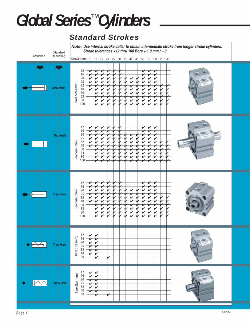
5 10 15 20 25 30 35 40 45 50 75 100 125 150
✔ ✔ ✔ ✔ ✔ ✔ ✔ ✔ ✔ ✔ ✔ ✔ ✔ ✔ ✔ ✔ ✔ ✔ ✔ ✔ ✔ ✔ ✔ ✔ ✔ ✔ ✔ ✔ ✔ ✔ ✔ ✔ ✔ ✔ ✔ ✔ ✔ ✔ ✔ ✔ ✔ ✔ ✔ ✔ ✔ ✔ ✔ ✔ ✔ ✔ ✔ ✔ ✔ ✔ ✔ ✔ ✔ ✔ ✔ ✔ ✔ ✔ ✔ ✔ ✔ ✔ ✔ ✔ ✔ ✔ ✔ ✔ ✔ ✔ ✔ ✔ ✔ ✔ ✔ ✔ ✔ ✔ ✔ ✔ ✔ ✔ ✔ ✔ ✔ ✔ ✔ ✔ ✔ ✔ ✔ ✔ ✔ ✔ ✔ ✔ ✔ ✔ ✔ ✔ ✔ ✔ ✔ ✔ ✔ ✔ ✔ ✔ ✔ ✔ ✔ ✔ ✔ ✔ ✔ ✔ ✔ ✔
Standard Strokes
StandardMountingActuation
Thru Hole
✔ ✔ ✔ ✔ ✔ ✔ ✔ ✔ ✔ ✔ ✔ ✔ ✔ ✔ ✔ ✔ ✔ ✔ ✔ ✔ ✔ ✔ ✔ ✔ ✔ ✔ ✔ ✔ ✔ ✔ ✔ ✔ ✔ ✔ ✔ ✔ ✔ ✔ ✔ ✔ ✔ ✔ ✔ ✔ ✔ ✔ ✔ ✔ ✔ ✔ ✔ ✔ ✔ ✔ ✔ ✔ ✔ ✔ ✔ ✔ ✔ ✔ ✔ ✔ ✔ ✔ ✔ ✔ ✔ ✔ ✔ ✔ ✔ ✔ ✔ ✔ ✔ ✔ ✔ ✔ ✔ ✔ ✔ ✔ ✔ ✔ ✔ ✔ ✔ ✔ ✔ ✔ ✔ ✔ ✔ ✔ ✔ ✔ ✔ ✔ ✔ ✔ ✔ ✔ ✔ ✔ ✔ ✔ ✔ ✔ ✔ ✔ ✔ ✔ ✔ ✔ ✔ ✔ ✔ ✔ ✔ ✔
Thru Hole
Thru Hole
Thru Hole
Thru Hole
✔ ✔ ✔ ✔ ✔ ✔ ✔ ✔ ✔ ✔ ✔ ✔ ✔ ✔ ✔ ✔ ✔ ✔ ✔ ✔ ✔ ✔ ✔ ✔ ✔ ✔ ✔ ✔ ✔ ✔ ✔ ✔ ✔ ✔ ✔ ✔ ✔ ✔ ✔ ✔ ✔ ✔ ✔ ✔ ✔ ✔ ✔ ✔ ✔ ✔ ✔ ✔ ✔ ✔ ✔ ✔ ✔ ✔ ✔ ✔ ✔ ✔ ✔ ✔ ✔ ✔ ✔ ✔ ✔ ✔ ✔ ✔ ✔ ✔ ✔ ✔ ✔ ✔ ✔ ✔ ✔ ✔ ✔ ✔ ✔ ✔ ✔ ✔ ✔ ✔ ✔ ✔ ✔ ✔ ✔ ✔ ✔ ✔ ✔ ✔ ✔ ✔ ✔ ✔ ✔ ✔ ✔ ✔ ✔ ✔ ✔ ✔ ✔ ✔ ✔ ✔ ✔ ✔ ✔ ✔ ✔ ✔
Bore
Size
(mm
)
121620253240506380100
12162025324050
12162025324050
121620253240506380100
121620253240506380100
✔ ✔ ✔ ✔ ✔ ✔ ✔ ✔ ✔ ✔ ✔ ✔ ✔ ✔
Stroke (mm)
Note: Use internal stroke collar to obtain intermediate stroke from longer stroke cylinders. Stroke tolerances ■12 thru 100 Bore + 1.0 mm / – 0
9-22-04

Page 5
➧ ➧ ➧ ➧ ➧ ➧ ➧ ➧ ➧ ➧ ➧ ➧
MagneticPistonSeries
TappedHole
Features and Options
Standard Series
FlangeMounts
Foot Mount
Rear ClevisMount Bumpers
High Temp Seals
AdjustableStroke
Male RodEnd
Rear BossMount
Front BossMount
Cylinder OptionsMounting Options
Standard Strokes, Features & Options Availability
Double Acting, Single Rod Non-Rotating
Double Acting, Double Rod Non-Rotating
✔✔✔ ✔✔ ✔ ✔ ✔ ✔ ✔ ✔ ✔
✔✔✔ ✔✔ ✔ ✔ ✔ ✔ ✔
Single Acting Spring Retract
✔✔✔✔✔✔✔
Single Acting Spring Extend
✔✔✔✔✔✔✔
9-22-04
Double Acting Single Rod
✔✔✔✔ ✔ ✔✔ ✔ ✔ ✔ ✔ ✔
Double Acting Double Rod
✔✔ ✔ ✔✔✔✔✔✔✔

Page 6
Global Series™Cylinders – Construction
Standard Cylinder Models
SRRBPRTS
103
4 511 6 1 11
7
5
2
9
153 4 511 6 1 11 72 910
3
5
7
2
1212
11111 6 5
4
9
113 510 6
1
8
29
5
4
7
103
4
5
11 6 1
11
7
29
5
8
103
45
11 61 16
72
9
5
11
103
511
6111 45
10
69
2
Single Acting/Spring Extend Single Rod/Double ActingMale Rod Thread Optional
Single Acting/Spring Retract
Single Rod/Boss Mount
Single Rod/Nonrotating Single Rod/Bumpers Front & Rear
Double Rod/Double Acting
Extended Strokes
Specifi cations subject to change without notice or incurring obligation.
Basic Construction
Note 1: Bearing material for 12, 16 & 20 mm bores is hard anodized aluminumNote 2: Magnetic material 12 , 16 & 20mm bores: rare earth neodymiumNote 3: Magnetic material 25mm bore and up: barium ferrite
13
3 10 5 511 4 6 1 11 729
Cylinder Body Material – is a custom aluminum extrusion with integral dovetail slots to provide mounting for piston position sensors. Its heavy wall prohibits damage to the bore from external infl uences.
The Bore is Polished – to produce a fi ne crosshatch fi nish. This fi nish, unlike an ultra-smooth fi nish, provides minute oil rings in which the lubrication can lie and support the seal as it moves along the surface. This surface fi nish and lubrication lowers friction and prolongs seal life.
The Cylinder is Hard Anodized – inside and out. Hard anodizing is an electrochemical process which provides a very dense surface of aluminum oxide that actually impregnates the base aluminum. It forms an extremely hard (60 Rc) surface with a low coeffi cient of friction. Hardness, corrosion resistance and wear resistance exceeds that of chrome plated steel.
An Extra Long Rod Bearing – provides long and rigid support for the piston rod. The bearing material is Hard Anodized Aluminum on the small 12, 16 & 20 mm bores, and Duralon® on all larger bore sizes. See the chart comparing physical properties on page 2. The bushing cap and end cap are held in place by a lockring.
The Piston Rod – is Hard Chrome Plated Stainless Steel. The standard rod end is fi ne thread tapped and has long wrench fl ats.
Piston Construction – The piston is aluminum for light weight. A counterbore locates the piston rod with precise concentricity for smooth cylinder performance.
For single rod cylinders – the piston is attached to the piston rod with a socket fl at head screw which is torqued for both proper preload on the screw and secure clamping
9-22-04
Quick Reference to Components
DescriptionCylinder bodyPistonPiston rodBushing capLock ringRod bearingEnd capSpringPiston sealRod sealGasketBumperRod end nutAnnular magnetRod sealBearing strip
MaterialHard Anodized AluminumAluminum alloyStainless steelAluminum alloyCarbon steelDuralon®
Aluminum alloyMusic wireInternal lube O-ringInternal lube O-ringBuna NRubberCarbon steelRubber bondedBuna NTFE compound
No.12345678910111213141516
NoteExtruded with dovetails Hard chrome platedBlack anodizedZinc chromateSee note 1 belowBlack anodized
Viton optionalViton optionalViton optional
PlatedSee notes 2 & 3 belowMolded shape – U cupSee page 7
Page 7
143
4
5
11 610 9
13
5
7
2
1
11
Air Cylinders with 35 Years Manufacturing Experience Built-in
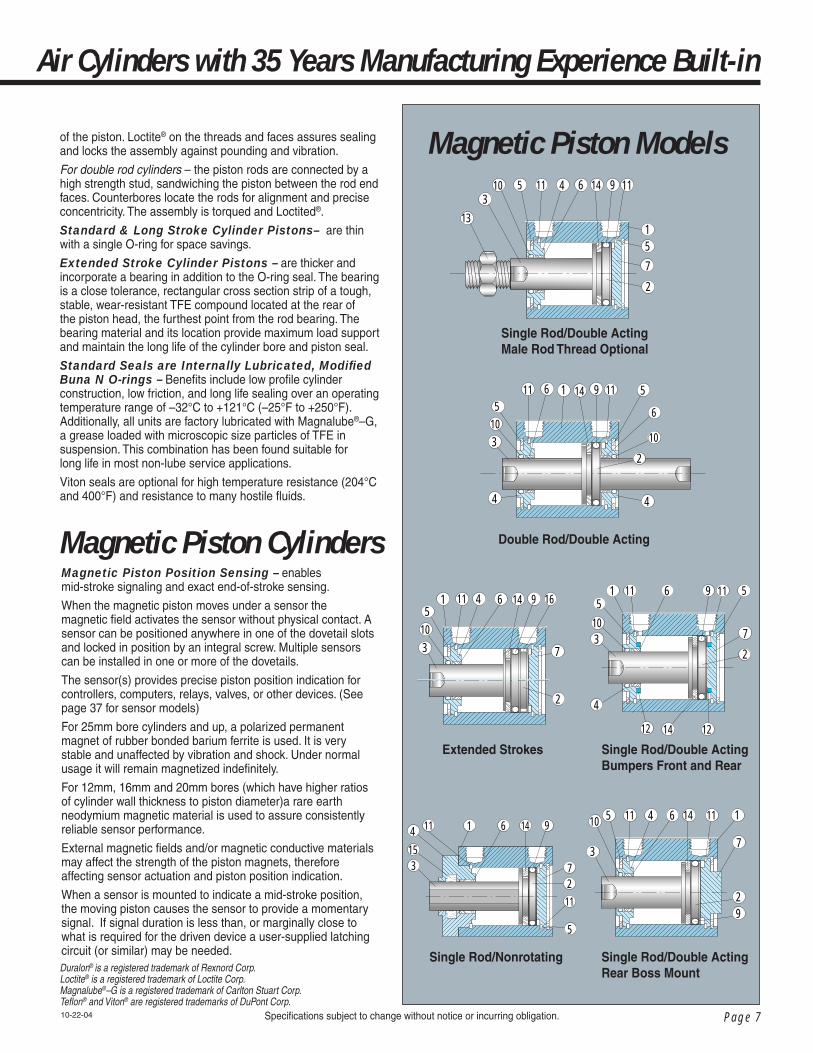
Magnetic Piston Models
103
4
511 61 11
7
2
9
1212
5
14
10
3
45 11 6 111
7
14
92
153
4
5
11 61
11
9
27
14
103
45
11 61 16
7
2
14 9
Single Rod/Double Acting Bumpers Front and Rear
Single Rod/Double Acting Rear Boss Mount
Single Rod/Nonrotating
Single Rod/Double ActingMale Rod Thread Optional
Double Rod/Double Acting
Extended Strokes
103
4
56 1 14 511
4
6
10
11
2
9
Specifi cations subject to change without notice or incurring obligation.
of the piston. Loctite® on the threads and faces assures sealing and locks the assembly against pounding and vibration.
For double rod cylinders – the piston rods are connected by a high strength stud, sandwiching the piston between the rod end faces. Counterbores locate the rods for alignment and precise concentricity. The assembly is torqued and Loctited®.
Standard & Long Stroke Cylinder Pistons– are thin with a single O-ring for space savings.
Extended Stroke Cylinder Pistons – are thicker and incorporate a bearing in addition to the O-ring seal. The bearing is a close tolerance, rectangular cross section strip of a tough, stable, wear-resistant TFE compound located at the rear of the piston head, the furthest point from the rod bearing. The bearing material and its location provide maximum load support and maintain the long life of the cylinder bore and piston seal.
Standard Seals are Internally Lubricated, Modifi ed Buna N O-rings – Benefi ts include low profi le cylinder construction, low friction, and long life sealing over an operating temperature range of –32°C to +121°C (–25°F to +250°F). Additionally, all units are factory lubricated with Magnalube®–G, a grease loaded with microscopic size particles of TFE in suspension. This combination has been found suitable for long life in most non-lube service applications.
Viton seals are optional for high temperature resistance (204°C and 400°F) and resistance to many hostile fl uids.
Magnetic Piston Position Sensing – enables mid-stroke signaling and exact end-of-stroke sensing.
When the magnetic piston moves under a sensor the magnetic fi eld activates the sensor without physical contact. A sensor can be positioned anywhere in one of the dovetail slots and locked in position by an integral screw. Multiple sensors can be installed in one or more of the dovetails.
The sensor(s) provides precise piston position indication for controllers, computers, relays, valves, or other devices. (See page 37 for sensor models)
For 25mm bore cylinders and up, a polarized permanent magnet of rubber bonded barium ferrite is used. It is very stable and unaffected by vibration and shock. Under normal usage it will remain magnetized indefi nitely.
For 12mm, 16mm and 20mm bores (which have higher ratios of cylinder wall thickness to piston diameter)a rare earth neodymium magnetic material is used to assure consistently reliable sensor performance.
External magnetic fi elds and/or magnetic conductive materials may affect the strength of the piston magnets, therefore affecting sensor actuation and piston position indication.
When a sensor is mounted to indicate a mid-stroke position, the moving piston causes the sensor to provide a momentary signal. If signal duration is less than, or marginally close to what is required for the driven device a user-supplied latching circuit (or similar) may be needed.
Magnetic Piston Cylinders
10-22-04
Duralon® is a registered trademark of Rexnord Corp. Loctite® is a registered trademark of Loctite Corp.Magnalube®–G is a registered trademark of Carlton Stuart Corp.Tefl on® and Viton® are registered trademarks of DuPont Corp.

Page 8
Global Series™Cylinders
Specifi cations subject to change without notice or incurring obligation.
– Specifi cations
10-22-04
Connectors for the NEWMagnetic Position Sensors
See page 36
Conversions
Multiply by Newton ................0.102 ............ Kg (force) lb (force) ...............4.448 .............. Newton lb (force) ...............0.454 ............ Kg (force) psi ....................0.069 ..................bar
Force (lb) = P (psi) x A (in2)
Force (Newton) = P (bar) x A (cm2) x 10
Effective Piston Areas
Push Pull
in2
.13 .23 .37 .59 .94 1.64 2.56 4.35 7.03 11.08
cm2
.8 1.5 2.4 3.8 6.0 10.6 16.4 28.0 45.4 71.4
Bore – mm 12 16 20 25 32 40 50 63 80 100
in2
.17 .31 .49 .76 1.25 1.95 3.04 4.83 7.79 12.17
cm2
1.1 2.0 3.1 4.9 8.0 12.6 19.6 31.2 50.3 78.5
Bore – mm 12 16 20 25 32 40 50
Pre-load End of Stroke
Spring Retract Forces
kg 0.4 0.6 0.6 1.1 1.5 1.3 2.5
lbs 0.9 1.3 1.3 2.4 3.3 2.9 5.5
kg 1.4 1.5 1.6 2.1 2.4 3.1 5.5
lbs 3.1 3.3 3.5 4.6 5.3 6.8 12.1
Bore – mm 12 16 20 25 32 40 50
lbs 0.7 0.9 1.1 2.2 4.4 4.4 5.5
kg 0.3 0.4 0.5 1.0 2.0 2.0 2.5
Pre-load End of Stroke lbs
2.4 4.6 6.2 6.6 6.6 6.6 18.7
kg 1.1 2.1 3.0 3.0 3.0 3.0 8.5
Spring Extend Forces
Strokes in millimeters
Note: Weights in Grams (Pounds)
Estimated Cylinder Weights - Double Acting, Single Rod Models
5 40 (0.088) 61 (0.135) 91 (0.201) 118 (0.260) 157 (0.346) 272 (0.600)
– –––
10 47 (.104) 72 (.159) 112 (.247) 139 (.306) 180 (.397) 294 (.648) 401 (.884) 647 (1.43) 1443 (3.18)2208 (4.87)
30 75 (.165) 116 (.256) 193 (.426) 224 (.494) 270 (.595) 382 (.842) 551 (1.21) 807 (1.78) 1804 (3.98)2632 (5.80)
50 109 (.240) 160 (.353) 254 (.559) 287 (.631) 339 (.746) 448 (.986) 663 (1.46) 927 (2.04) 2076 (4.57)2950 (6.49)
75 140 (.309) 204 (.450) 311 (.684) 408 (.899) 522 (1.15) 623 (1.37) 958 (2.11) 1257 (2.77) 2830 (6.24)3801 (8.38)
100 172 (.378) 248 (.546) 375 (.826) 484 (1.067) 636 (1.40) 733 (1.62) 1102 (2.43) 1464 (3.23) 3296 (7.27)4318 (9.52)
125––––
824 (1.81)1077 (2.37) 1848 (4.07)2243 (4.94) 3494 (7.70) 5036 (11.10)
150––––
936 (2.06) 1211 (2.67)2066 (4.55)2499 (5.51)3870 (8.52)5531 (12.18)
2 (.004) 3 (.007) 7 (.015) 17 (.04) 40 (.09) 40 (.09) 80 (.18) 80 (.18) 160 (.35) 270 (.60)
Additional weight for
male thread
12 (.03) 17 (.04) 25 (.05) 29 (.06) 39 (.09) 54 (.12) 80 (.18) 102 (.24) 143 (.31) 282 (.62)
Additional weight for magnetic
piston
Bore mm
12 16 20 25 32 40 50 63 80 100
Page 9
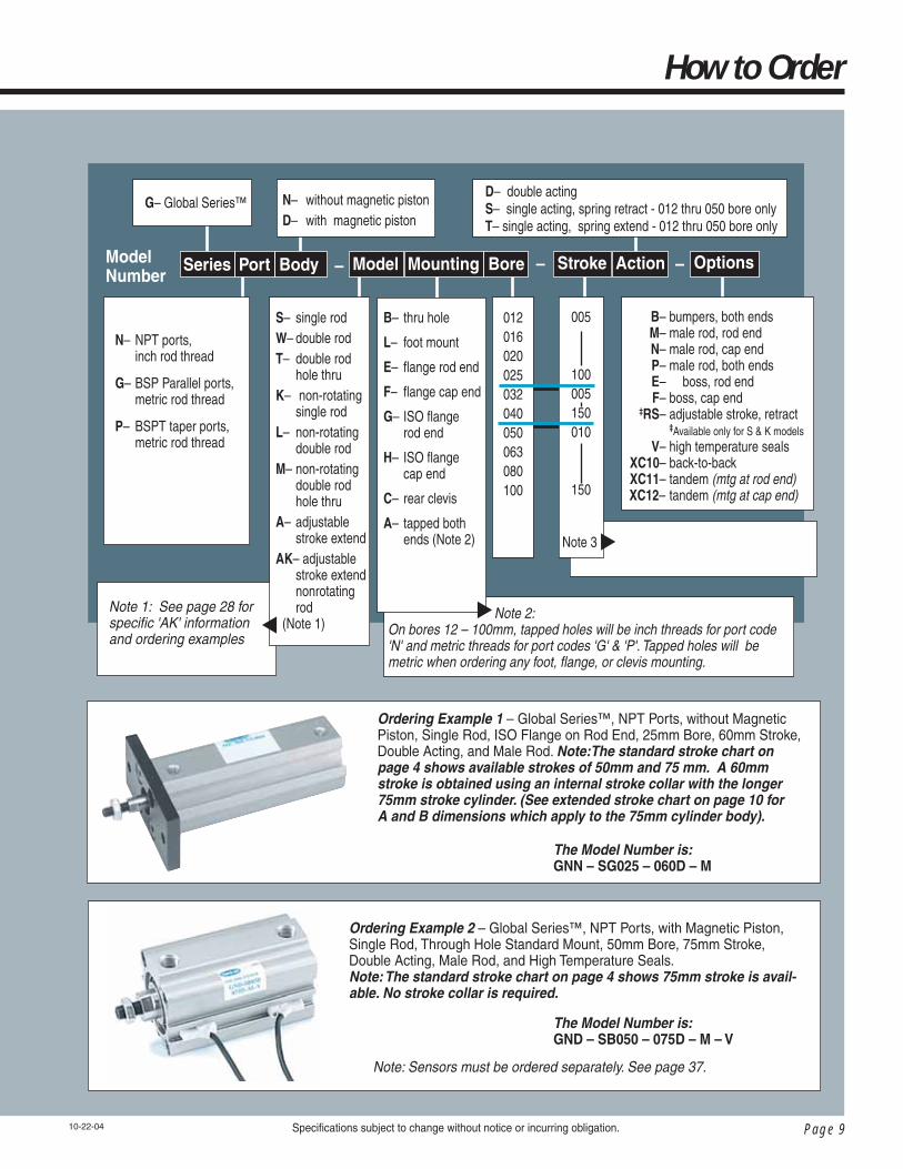
Ordering Example 1 – Global Series™, NPT Ports, without Magnetic Piston, Single Rod, ISO Flange on Rod End, 25mm Bore, 60mm Stroke, Double Acting, and Male Rod. Note:The standard stroke chart on page 4 shows available strokes of 50mm and 75 mm. A 60mm stroke is obtained using an internal stroke collar with the longer 75mm stroke cylinder. (See extended stroke chart on page 10 for A and B dimensions which apply to the 75mm cylinder body).
The Model Number is: GNN – SG025 – 060D – M
The Model Number is: GND – SB050 – 075D – M – V
Specifi cations subject to change without notice or incurring obligation.
012016020025032040050063080100
005
100005150010
150
G– Global Series™D– double actingS– single acting, spring retract - 012 thru 050 bore onlyT– single acting, spring extend - 012 thru 050 bore only
N– without magnetic pistonD– with magnetic piston
– ––Series Port Body OptionsModel Mounting Bore Stroke ActionModel Number
Note 3
S– single rodW– double rodT– double rod hole thruK– non-rotating single rodL– non-rotating double rodM– non-rotating double rod hole thruA– adjustable stroke extendAK– adjustable stroke extend nonrotating rod (Note 1)
▼
How to Order
B– thru hole
L– foot mount
E– fl ange rod end
F– fl ange cap end
G– ISO fl ange rod end
H– ISO fl ange cap end
C– rear clevis
A– tapped both ends (Note 2)
▼ Note 2: On bores 12 – 100mm, tapped holes will be inch threads for port code 'N' and metric threads for port codes 'G' & 'P'. Tapped holes will be metric when ordering any foot, fl ange, or clevis mounting.
▼
N– NPT ports, inch rod thread
G– BSP Parallel ports, metric rod thread
P– BSPT taper ports, metric rod thread
10-22-04
B– bumpers, both ends M– male rod, rod end N– male rod, cap end P– male rod, both ends E– boss, rod end F– boss, cap end ‡RS– adjustable stroke, retract ‡Available only for S & K models V– high temperature seals XC10– back-to-back XC11– tandem (mtg at rod end)XC12– tandem (mtg at cap end)
Note 1: See page 28 for specifi c 'AK' information and ordering examples
Ordering Example 2 – Global Series™, NPT Ports, with Magnetic Piston, Single Rod, Through Hole Standard Mount, 50mm Bore, 75mm Stroke, Double Acting, Male Rod, and High Temperature Seals. Note: The standard stroke chart on page 4 shows 75mm stroke is avail-able. No stroke collar is required.
Note: Sensors must be ordered separately. See page 37.

Page 10
Global Series™Cylinders
ØD
A + STROKE
L B + STROKE
Q Q
MM–2
E1–2
E1
FLATSK
E1
ØI ØN THRU (2)ØO C'BORE (4)
E2 E2–2
45E1–2
H THREADS
P 2 PLACES
45
Specifi cations subject to change without notice or incurring obligation.
Note 1- See page 4 for complete stroke availabilityNote 2- Chart dimensions are shown as mm (inches)
Dimensional Data
Ø12 - Ø25 mm Bores
5-05-06
H (Threads) x dp minimuminch or metric
#8-32 x .21dp M3 x 0.5 – 5 dp #8-32 x .21dp M4 x 0.7 – 5 dp #10-32 x .28 dp M5 x 0.8 – 7 dp 1/4-28 x .39 dp M6 x 1.0 – 10 dp 5/16-24 x .50 dp M8 x 1.25 – 12 dp 5/16-24 x .50 dp M8 x 1.25 – 12 dp 3/8-24 x .50 dp M8 x 1.25 – 12 dp 1/2-20 x .50 dp M10 x 1.5 – 12 dp 1/2-20 x .50 dp M10 x 1.5 – 12 dp 5/8-18 x .88 dp M16 x 2.0 – 22 dp 3/4-16 x .88 dp M20 x 2.5 – 22 dp
E223 (0.90) 27.2 (1.07) 31.2 (1.23) 36.9 (1.45) –
––––––
E1 25 (0.98) 29 (1.14) 36 (1.42) 40 (1.57) 44.5 (1.75) 44.5 (1.75) 52 (2.05) 63.7 (2.51) 76.7 (3.02) 97.8 (3.85) 115.3 (4.54)
ØD 6 (0.236) 8 (0.315) 10 (0.394) 12 (0.472) 16 (0.630) 16 (0.630) 16 (0.630) 20 (0.787) 20 (0.787) 25 (0.984) 30 (1.181)
B17.0 (0.67)18.5 (0.73)19.5 (0.77)22.5 (0.89)23.0 (0.91)23.0 (0.91)29.5 (1.16)30.5 (1.20)36.0 (1.42)43.5 (1.71)53.0 (2.09)
A20.5 (0.81)22.0 (0.87)24.0 (0.94) 27.5 (1.08)30.0 (1.18)30.0 (1.18)36.5 (1.44)38.5 (1.52)44.0 (1.73)53.5 (2.11)65.0 (2.56)
Bore mm(Nom. Inch) 12 (1/2) 16 (5/8) 20 (3/4) 25 (1) 32 (1-1/4) 40 (1-1/2) 50 (2) 63 (2-1/2) 80 (3-1/4) 100 (4)
ØI 31.5 (1.24) 37.1 (1.46) 47 (1.85) 51.3 (2.02) 58.9 (2.32) 58.9 (2.32) 69 (2.72) 84.9 (3.34) 101.8 (4.01) 129.8 (5.11) 153.9 (6.06)
Stroke Range 5~30 (0.20~1.18) 5~30 (0.20~1.18) 5~50 (0.20~2.0) 5~50 (0.20~2.0) 5 only (0.20) 10~50 (0.39~2.0) 5~50 (0.20~2.0) 10~50 (0.39~2.0) 10~50 (0.39~2.0) 10~50 (0.39~2.0) 10~50 (0.39~2.0)
Long Stroke Extended StrokeStroke mm
––––
75, 10075, 10075, 10075, 10075, 10075, 100
Q 8.9 (.35) 10.2 (.40) 12.1 (.48) 12.7 (.50) 12.7 (.50) 12.7 (.50) 13.2 (.52) 18.5 (.73) 14.0 (.55) 18.0 (.71)
Stroke mm50, 75, 10050, 75, 100
75, 10075, 100125, 150125, 150125, 150125, 150125, 150125, 150
A 37.3 (1.47) 39.7 (1.56) 46.1 (1.82) 52.5 (2.07) 54.8 (2.16) 62.5 (2.46) 67.3 (2.65) 72.6 (2.86) 79.5 (3.13) 88.7 (3.49)
B 33.8 (1.33) 36.2 (1.42) 41.6 (1.64) 47.5 (1.87) 47.8 (1.88) 55.5 (2.19) 59.3 (2.33) 64.6 (2.54) 69.5 (2.74) 76.7 (3.02)
Q––––
8.7 (.34) 9.2 (.36) 10.5 (.41) 11.5 (.45) 14.0 (.55) 18.0 (.71)
B––––
33.0 (1.30) 39.5 (1.56) 40.5 (1.59) 46.0 (1.81) 53.5 (2.11) 63.0 (2.48)
A––––
40.0 (1.57) 46.5 (1.83) 48.5 (1.91) 54.0 (2.13) 63.5 (2.50) 75.0 (2.95)
Bore mm 12 16 20 25 32 40 50 63 80 100

Page 11
Double Acting, Single Rod Models
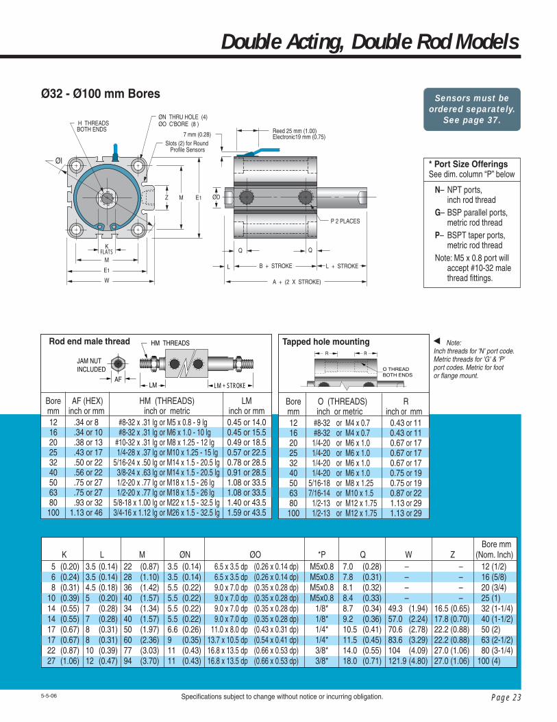
Note: Inch threads for 'N' port code.Metric threads for 'G' & 'P' port codes. Metric for foot, fl ange, or clevis mount.
KFLATS
Q Q
L B + STROKE
A + STROKE
Z M E1
M
E1
W
ØN THRU HOLE (4)ØO C'BORE (8 )
H THREADS
ØI
ØD
P 2 PLACES
Specifi cations subject to change without notice or incurring obligation.
Ø32 - Ø100 mm Bores
5-5-06
Bore mm(Nom. Inch) 12 (1/2) 16 (5/8) 20 (3/4) 25 (1) 32 (1-1/4) 40 (1-1/2) 50 (2) 63 (2-1/2) 80 (3-1/4) 100 (4)
L3.5 (0.14)3.5 (0.14)4.5 (0.18)5 (0.20)7 (0.28)7 (0.28)7 (0.28)8 (0.31)8 (0.31)10 (0.39)12 (0.47)
M22 (0.87)28 (1.10)36 (1.42)40 (1.57)34 (1.34)34 (1.34)40 (1.57)50 (1.97)60 (2.36)77 (3.03)94 (3.70)
ØN3.5 (0.14)3.5 (0.14)5.5 (0.22)5.5 (0.22)5.5 (0.22)5.5 (0.22)5.5 (0.22)6.6 (0.26)9 (0.35)11 (0.43)11 (0.43)
ØO 6.5 x 3.5 dp (0.26 x 0.14 dp) 6.5 x 3.5 dp (0.26 x 0.14 dp) 9.0 x 7.0 dp (0.35 x 0.28 dp) 9.0 x 7.0 dp (0.35 x 0.28 dp) 9.0 x 7.0 dp (0.35 x 0.28 dp) 9.0 x 7.0 dp (0.35 x 0.28 dp) 9.0 x 7.0 dp (0.35 x 0.28 dp) 11.0 x 8.0 dp (0.43 x 0.31 dp) 13.7 x 10.5 dp (0.54 x 0.41 dp) 16.8 x 13.5 dp (0.66 x 0.53 dp) 16.8 x 13.5 dp (0.66 x 0.53 dp)
*PM5x0.8M5x0.8M5x0.8M5x0.8M5x0.8
1/8*1/8*1/4*1/4*3/8*3/8*
Q7.0 (0.28)7.8 (0.31)8.1 (0.32)8.4 (0.33)8.7 (0.34)8.7 (0.34)9.2 (0.36)10.5 (0.41)11.5 (0.45)14.0 (0.55)18.0 (0.71)
W – – – –49.3 (1.94)49.3 (1.94)57.0 (2.24)70.6 (2.78)83.6 (3.29)104 (4.09)121.9 (4.80)
Z – – – –16.5 (0.65)16.5 (0.65)17.8 (0.70)22.2 (0.88)22.2 (0.88)27.0 (1.06)27.0 (1.06)
K 5 (0.20) 6 (0.24) 8 (0.31)10 (0.39)14 (0.55)14 (0.55)14 (0.55)17 (0.67)17 (0.67)22 (0.87)27 (1.06)
▼
* Port Size OfferingsSee dim. column “P” below
N– NPT ports, inch rod threadG– BSP parallel ports, metric rod threadP– BSPT taper ports, metric rod threadNote: M5 x 0.8 port will accept #10-32 male thread fi ttings.
Bore mm 12 16 20 25 32 40 50 63 80 100
LM inch or mm 0.45 or 14.0 0.45 or 15.5 0.49 or 18.5 0.57 or 22.5 0.78 or 28.5 0.91 or 28.5 1.08 or 33.5 1.08 or 33.5 1.40 or 43.5 1.59 or 43.5
Rod end male thread
HM (THREADS) inch or metric #8-32 x .31 lg or M5 x 0.8 - 9 lg #8-32 x .31 lg or M6 x 1.0 - 10 lg #10-32 x .31 lg or M8 x 1.25 - 12 lg 1/4-28 x .37 lg or M10 x 1.25 - 15 lg 5/16-24 x .50 lg or M14 x 1.5 - 20.5 lg 3/8-24 x .63 lg or M14 x 1.5 - 20.5 lg 1/2-20 x .77 lg or M18 x 1.5 - 26 lg 1/2-20 x .77 lg or M18 x 1.5 - 26 lg 5/8-18 x 1.00 lg or M22 x 1.5 - 32.5 lg 3/4-16 x 1.12 lg or M26 x 1.5 - 32.5 lg
AF (HEX)inch or mm
.34 or 8 .34 or 10 .38 or 13 .43 or 17 .50 or 22 .56 or 22 .75 or 27 .75 or 27 .93 or 32 1.13 or 46
JAM NUT INCLUDED
HM THREADS
LMAF
Tapped hole mounting
Rinch or mm
0.43 or 110.43 or 110.67 or 170.67 or 170.67 or 170.75 or 190.75 or 190.87 or 221.13 or 291.13 or 29
R R
O THREAD BOTH ENDS
O (THREADS) inch or metric #8-32 or M4 x 0.7 #8-32 or M4 x 0.7 1/4-20 or M6 x 1.0 1/4-20 or M6 x 1.0 1/4-20 or M6 x 1.0 1/4-20 or M6 x 1.0 5/16-18 or M8 x 1.25 7/16-14 or M10 x 1.5 1/2-13 or M12 x 1.75 1/2-13 or M12 x 1.75
Bore mm 12 16 20 25 32 40 50 63 80 100

Page 12
Global Series™Cylinders
Note 1- See page 4 for complete stroke availabilityNote 2- Chart dimensions are shown as mm (inches)
Dimensional Data
Specifi cations subject to change without notice or incurring obligation. 5-5-06
Ø12 - Ø25 mm Bores
ØD
L B + STROKE
Q Q
MM–2
E1–2
E1
FLATSK
E1
ØI ØN THRU (2)ØO C'BORE (4)
E2 E2–2
45E1–2
H THREADSBOTH ENDS
P 2 PLACES
L + STROKE
A + ( 2 X STROKE)
45
H (Threads) x dp minimuminch or metric
#8-32 x .21dp M3 x 0.5 – 5 dp #8-32 x .21dp M4 x 0.7 – 5 dp #10-32 x .28 dp M5 x 0.8 – 7 dp 1/4-28 x .39 dp M6 x 1.0 – 10 dp 5/16-24 x .50 dp M8 x 1.25 – 12 dp 5/16-24 x .50 dp M8 x 1.25 – 12 dp 3/8-24 x .50 dp M8 x 1.25 – 12 dp 1/2-20 x .50 dp M10 x 1.5 – 12 dp 1/2-20 x .50 dp M10 x 1.5 – 12 dp 5/8-18 x .88 dp M16 x 2.0 – 22 dp 3/4-16 x .88 dp M20 x 2.5 – 22 dp
E2 23 (0.90) 27.2 (1.07) 31.2 (1.23) 36.9 (1.45) –
––––––
E1 25 (0.98) 29 (1.14) 36 (1.42) 40 (1.57) 44.5 (1.75) 44.5 (1.75) 52 (2.05) 63.7 (2.51) 76.7 (3.02) 97.8 (3.85) 115.3 (4.54)
ØD 6 (0.236) 8 (0.315) 10 (0.394) 12 (0.472) 16 (0.630) 16 (0.630) 16 (0.630) 20 (0.787) 20 (0.787) 25 (0.984) 30 (1.181)
Bore mm(Nom. Inch) 12 (1/2) 16 (5/8) 20 (3/4) 25 (1) 32 (1-1/4) 40 (1-1/2) 50 (2) 63 (2-1/2) 80 (3-1/4) 100 (4)
A32.2 (1.27)33.0 (1.30)35.0 (1.38)39.0 (1.54)44.5 (1.75)44.5 (1.75)54.0 (2.13)56.5 (2.22)58.0 (2.28)71.0 (2.80)84.5 (3.33)
ØI 31.5 (1.24) 37.1 (1.46) 47 (1.85) 51.3 (2.02) 58.9 (2.32) 58.9 (2.32) 69 (2.72) 84.9 (3.34) 101.8 (4.01) 129.8 (5.11) 153.9 (6.06)
B25.2 (0.99)26.0 (1.02)26.0 (1.02)29.0 (1.14)30.5 (1.20)30.5 (1.20)40.0 (1.57)40.5 (1.59)42.0 (1.65)51.0 (2.01)60.5 (2.38)
Stroke Range 5~30 (0.20~1.18) 5~30 (0.20~1.18) 5~50 (0.20~2.0) 5~50 (0.20~2.0) 5 only (0.20) 10~50 (0.39~2.0) 5~50 (0.20~2.0) 10~50 (0.39~2.0) 10~50 (0.39~2.0) 10~50 (0.39~2.0) 10~50 (0.39~2.0)
Model Code 'T'Bore
12 16 20 25 32 40 50 63 80 100
Hole Size NA (NA) 1.5 (.06) 1.5 (.06) 3.1 (.13) 3.1 (.13) 3.1 (.13) 4.0 (.16) 4.0 (.16) 6.3 (.25) 6.3 (.25)
Long Stroke Extended StrokeB
33.8 (1.33) 36.2 (1.42) 41.6 (1.64) 47.5 (1.87) 47.8 (1.88) 55.5 (2.19) 59.3 (2.33) 64.6 (2.54) 69.5 (2.74) 76.7 (3.02)
A 40.8 (1.61) 43.2 (1.70) 50.6 (1.99) 57.5 (2.26) 61.8 (2.43) 69.5 (2.74) 75.3 (2.96) 80.6 (3.17) 89.5 (3.52) 100.7 (3.96)
A––––
61.8 (2.43) 69.5 (2.74) 75.3 (2.96) 80.6 (3.17) 89.5 (3.52) 100.7 (3.96)
Stroke mm––––
75, 10075, 10075, 10075, 10075, 10075, 100
Bore mm 12 16 20 25 32 40 50 63 80 100
B––––
47.8 (1.88) 55.5 (2.19) 59.3 (2.33) 64.6 (2.54) 69.5 (2.74) 76.7 (3.02)
Q––––
12.7 (.50) 12.7 (.50) 13.2 (.52) 18.5 (.73) 14.0 (.55) 18.0 (.71)
Stroke mm50, 75, 10050, 75, 100
75, 10075, 100125, 150125, 150125, 150125, 150125, 150125, 150
Q 8.9 (.35) 10.2 (.40) 12.1 (.48) 12.7 (.50) 12.7 (.50) 12.7 (.50) 13.2 (.52) 18.5 (.73) 14.0 (.55) 18.0 (.71)

Page 13
Double Acting, Double Rod Models
KFLATS
Q Q
L B + STROKE
A + (2 X STROKE)
L + STROKE
M E1
ME1
W
ØN THRU HOLE (4)ØO C'BORE (8 )H THREADS
BOTH ENDS
ØI
ØDZ
P 2 PLACES
Specifi cations subject to change without notice or incurring obligation.5-17-06
Ø32 - Ø100 mm Bores
* Port Size OfferingsSee dim. column “P” below
N– NPT ports, inch rod threadG– BSP parallel ports, metric rod threadP– BSPT taper ports, metric rod threadNote: M5 x 0.8 port will accept #10-32 male thread fi ttings.
L3.5 (0.14)3.5 (0.14)4.5 (0.18)5 (0.20)7 (0.28)7 (0.28)7 (0.28)8 (0.31)8 (0.31)10 (0.39)12 (0.47)
K 5 (0.20) 6 (0.24) 8 (0.31)10 (0.39)14 (0.55)14 (0.55)14 (0.55)17 (0.67)17 (0.67)22 (0.87)27 (1.06)
M22 (0.87)28 (1.10)36 (1.42)40 (1.57)34 (1.34)34 (1.34)40 (1.57)50 (1.97)60 (2.36)77 (3.03)94 (3.70)
ØN3.5 (0.14)3.5 (0.14)5.5 (0.22)5.5 (0.22)5.5 (0.22)5.5 (0.22)5.5 (0.22)6.6 (0.26)9 (0.35)11 (0.43)11 (0.43)
ØO 6.5 x 3.5 dp (0.26 x 0.14 dp) 6.5 x 3.5 dp (0.26 x 0.14 dp) 9.0 x 7.0 dp (0.35 x 0.28 dp) 9.0 x 7.0 dp (0.35 x 0.28 dp) 9.0 x 7.0 dp (0.35 x 0.28 dp) 9.0 x 7.0 dp (0.35 x 0.28 dp) 9.0 x 7.0 dp (0.35 x 0.28 dp) 11.0 x 8.0 dp (0.43 x 0.31 dp) 13.7 x 10.5 dp (0.54 x 0.41 dp) 16.8 x 13.5 dp (0.66 x 0.53 dp) 16.8 x 13.5 dp (0.66 x 0.53 dp)
Z – – – –16.5 (0.65)16.5 (0.65)17.8 (0.70)22.2 (0.88)22.2 (0.88)27.0 (1.06)27.0 (1.06)
W – – – –49.3 (1.94)49.3 (1.94)57.0 (2.24)70.6 (2.78)83.6 (3.29)104 (4.09)121.9 (4.80)
Q7.0 (0.28)7.8 (0.31)8.1 (0.32)8.4 (0.33)8.7 (0.34)8.7 (0.34)9.2 (0.36)10.5 (0.41)11.5 (0.45)14.0 (0.55)18.0 (0.71)
*PM5x0.8M5x0.8M5x0.8M5x0.8M5x0.8
1/8*1/8*1/4*1/4*3/8*3/8*
Bore mm(Nom. Inch) 12 (1/2) 16 (5/8) 20 (3/4) 25 (1) 32 (1-1/4) 40 (1-1/2) 50 (2) 63 (2-1/2) 80 (3-1/4) 100 (4)
Note: Inch threads for 'N' port code.Metric threads for 'G' & 'P' port codes. Metric for foot, fl ange, or clevis mount.
▼
Bore mm 12 16 20 25 32 40 50 63 80 100
HM (THREADS) inch or metric #8-32 x .31 lg or M5 x 0.8 - 9 lg #8-32 x .31 lg or M6 x 1.0 - 10 lg #10-32 x .31 lg or M8 x 1.25 - 12 lg 1/4-28 x .37 lg or M10 x 1.25 - 15 lg 5/16-24 x .50 lg or M14 x 1.5 - 20.5 lg 3/8-24 x .63 lg or M14 x 1.5 - 20.5 lg 1/2-20 x .77 lg or M18 x 1.5 - 26 lg 1/2-20 x .77 lg or M18 x 1.5 - 26 lg 5/8-18 x 1.00 lg or M22 x 1.5 - 32.5 lg 3/4-16 x 1.12 lg or M26 x 1.5 - 32.5 lg
LMinch or mm0.45 or 14.00.45 or 15.50.49 or 18.50.57 or 22.50.78 or 28.50.91 or 28.51.08 or 33.51.08 or 33.51.40 or 43.51.59 or 43.5
AF (HEX)inch or mm
.34 or 8 .34 or 10 .38 or 13 .43 or 17 .50 or 22 .56 or 22 .75 or 27 .75 or 27 .93 or 32 1.13 or 46
JAM NUT INCLUDED
HM THREADS
LM + STROKELMAF
Tapped hole mountingR R
O THREAD BOTH ENDS
Bore mm 12 16 20 25 32 40 50 63 80 100
O (THREADS) inch or metric #8-32 or M4 x 0.7 #8-32 or M4 x 0.7 1/4-20 or M6 x 1.0 1/4-20 or M6 x 1.0 1/4-20 or M6 x 1.0 1/4-20 or M6 x 1.0 5/16-18 or M8 x 1.25 7/16-14 or M10 x 1.5 1/2-13 or M12 x 1.75 1/2-13 or M12 x 1.75
Rinch or mm
0.43 or 110.43 or 110.67 or 170.67 or 170.67 or 170.75 or 190.75 or 190.87 or 221.13 or 291.13 or 29
Rod end male thread

Page 14
Global Series™Cylinders
5-5-06
Ø12 - Ø25 mm Bores
Q
L
G
P 2 PLACES
KE1
E1
A + STROKE
B + STROKE
ØDH TAP
ØT
ØN THRU (2)ØO C'BORE (4)
QB2
E2
M
M–2
ØI
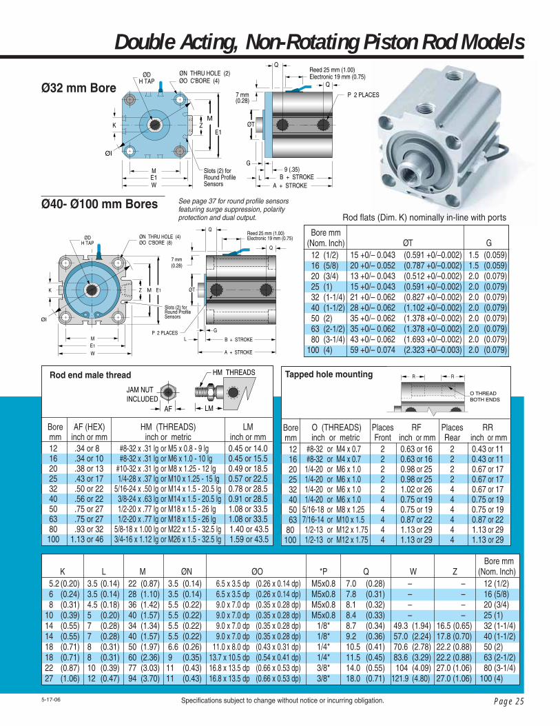
Rod fl ats (Dim. K) nominally in-line with ports
Specifi cations subject to change without notice or incurring obligation.
WarningTHIS CYLINDER HAS A NON-ROTATING ROD. TO PREVENT INTERNAL DAMAGE HOLD ROD BY FLATS ONLY WHEN FULLY RETRACTED WHILE INSTALLING OR REMOVING ATTACHMENTS. DO NOT SCRATCH OR DENT SHAFT.
Note 1- See page 4 for complete stroke availabilityNote 2- Chart dimensions are shown as mm (inches)
Dimensional Data Bore size 12 16 20 25 32 40 50 63 80 100 Nonrotating rod accuracy ±2° ±1° ±1° ±1° ±0.8° ±0.8° ±0.8° ±0.8° ±0.8° ±0.8°
H (Threads) x dp minimumStroke Range
5~30 (0.20~1.18) 5~30 (0.20~1.18) 5~50 (0.20~2.0) 5~50 (0.20~2.0) 5 only (0.20) 10~50 (0.39~2.0) 5~50 (0.20~2.0) 10~50 (0.39~2.0) 10~50 (0.39~2.0) 10~50 (0.39~2.0) 10~50 (0.39~2.0)
B22.0 (0.87)23.5 (0.93)27.5 (1.08)30.5 (1.20)32.0 (1.26)32.0 (1.26)29.5 (1.16)30.5 (1.20)36.0 (1.42)43.5 (1.71)53.0 (2.09)
A25.5 (1.00)27.0 (1.06)32.0 (1.26) 35.5 (1.40)39.0 (1.54)39.0 (1.54)36.5 (1.44)38.5 (1.52)44.0 (1.73)53.5 (2.11)65.0 (2.56)
inch or metric #8-32 x .21dp M3 x 0.5 – 5 dp #8-32 x .21dp M4 x 0.7 – 5 dp #10-32 x .28 dp M5 x 0.8 – 7 dp 1/4-28 x .39 dp M6 x 1.0 – 10 dp 5/16-24 x .50 dp M8 x 1.25 – 12 dp 5/16-24 x .50 dp M8 x 1.25 – 12 dp 3/8-24 x .50 dp M8 x 1.25 – 12 dp 1/2-20 x .50 dp M10 x 1.5 – 12 dp 1/2-20 x .50 dp M10 x 1.5 – 12 dp 5/8-18 x .88 dp M16 x 2.0 – 22 dp 3/4-16 x .88 dp M20 x 2.5 – 22 dp
ØI 31.5 (1.24) 37.1 (1.46) 47 (1.85) 51.3 (2.02) 58.9 (2.32) 58.9 (2.32) 69 (2.72) 84.9 (3.34) 101.8 (4.01) 129.8 (5.11) 153.9 (6.06)
E1 25 (0.98) 29 (1.14) 36 (1.42) 40 (1.57) 44.5 (1.75) 44.5 (1.75) 52 (2.05) 63.7 (2.51) 76.7 (3.02) 97.8 (3.85) 115.3 (4.54)
E2 23 (0.90) 27.2 (1.07) 31.2 (1.23) 36.9 (1.45) –
––––––
ØD 6 (0.236) 8 (0.315) 10 (0.394) 12 (0.472) 16 (0.630) 16 (0.630) 16 (0.630) 20 (0.787) 20 (0.787) 25 (0.984) 30 (1.181)
Bore mm(Nom. Inch) 12 (1/2) 16 (5/8) 20 (3/4) 25 (1) 32 (1-1/4) 40 (1-1/2) 50 (2) 63 (2-1/2) 80 (3-1/4) 100 (4)
Long Stroke Extended StrokeB––––
42.0 (1.65) 39.5 (1.56) 40.5 (1.59) 46.0 (1.81) 53.5 (2.11) 63.0 (2.48)
Q––––
8.7 (.34) 9.2 (.36) 10.5 (.41) 11.5 (.45) 14.0 (.55) 18.0 (.71)
A––––
49.0 (1.93) 46.5 (1.83) 48.5 (1.91) 54.0 (2.13) 63.5 (2.50) 75.0 (2.95)
Stroke mm50, 75, 10050, 75, 100
75, 10075, 100125, 150125, 150125, 150125, 150125, 150125, 150
A 42.3 (1.67) 44.7 (1.76) 54.1 (2.13) 60.5 (2.38) 63.8 (2.51) 62.5 (2.46) 67.3 (2.65) 72.6 (2.86) 79.5 (3.13) 88.7 (3.49)
B 38.8 (1.53) 41.2 (1.62) 49.6 (1.95) 55.5 (2.19) 56.8 (2.24) 55.5 (2.19) 59.3 (2.33) 64.6 (2.54) 69.5 (2.74) 76.7 (3.02)
Q 8.9 (.35) 10.2 (.40) 12.1 (.48) 12.7 (.50) 12.7 (.50) 12.7 (.50) 13.2 (.52) 18.5 (.73) 14.0 (.55) 18.0 (.71)
Stroke mm––––
75, 10075, 10075, 10075, 10075, 10075, 100
Bore mm 12 16 20 25 32 40 50 63 80 100
Bore mm 12 16 20 25
B25 (.20)5 (.20)8 (.32)8 (.32)
* Port Size OfferingsSee dim. column “P” below
N– NPT ports, inch rod threadG– BSP parallel ports, metric rod threadP– BSPT taper ports, metric rod threadNote: M5 x 0.8 port will accept #10-32 male thread fi ttings.

Page 15
Double Acting, Nonrotating Piston Rod Models
Specifi cations subject to change without notice or incurring obligation.5-17-06
Ø40 - Ø100 mm Bores
K
Q Q
L
ØDH TAP
E1
W
P 2 PLACES
E1MZ ØT
G
B + STROKE
A + STROKE
M
ØN THRU HOLE (4)ØO C'BORE (8)
ØI
Ø32 mm Bore
K
Q Q
LE1W
P 2 PLACES
E1
MZ ØT
G
B + STROKEA + STROKE
M
ØN THRU HOLE (2)ØO C'BORE (4)
ØDH TAP
ØI
9 (.35)Slots (2) for Round ProfileSensors
Rod fl ats (Dim. K) nominally in-line with ports
O (THREADS) inch or metric #8-32 or M4 x 0.7 #8-32 or M4 x 0.7 1/4-20 or M6 x 1.0 1/4-20 or M6 x 1.0 1/4-20 or M6 x 1.0 1/4-20 or M6 x 1.0 5/16-18 or M8 x 1.25 7/16-14 or M10 x 1.5 1/2-13 or M12 x 1.75 1/2-13 or M12 x 1.75
PlacesFront
2222244444
RF inch or mm
0.63 or 160.63 or 160.98 or 250.98 or 251.02 or 260.75 or 190.75 or 190.87 or 221.13 or 291.13 or 29
PlacesRear
2222444444
RR inch or mm
0.43 or 110.43 or 110.67 or 170.67 or 170.67 or 170.75 or 190.75 or 190.87 or 221.13 or 291.13 or 29
Note: Inch threads for 'N' port code.Metric threads for 'G' & 'P' port codes. Metric for foot, fl ange, or clevis mount.
Tapped hole mounting
Boremm
12 16 20 25 32 40 50 63 80 100
R R
O THREAD BOTH ENDS
HM (THREADS) inch or metric #8-32 x .31 lg or M5 x 0.8 - 9 lg #8-32 x .31 lg or M6 x 1.0 - 10 lg #10-32 x .31 lg or M8 x 1.25 - 12 lg 1/4-28 x .37 lg or M10 x 1.25 - 15 lg 5/16-24 x .50 lg or M14 x 1.5 - 20.5 lg 3/8-24 x .63 lg or M14 x 1.5 - 20.5 lg 1/2-20 x .77 lg or M18 x 1.5 - 26 lg 1/2-20 x .77 lg or M18 x 1.5 - 26 lg 5/8-18 x 1.00 lg or M22 x 1.5 - 32.5 lg 3/4-16 x 1.12 lg or M26 x 1.5 - 32.5 lg
LMinch or mm0.45 or 14.00.45 or 15.50.49 or 18.50.57 or 22.50.78 or 28.50.91 or 28.51.08 or 33.51.08 or 33.5
1.40 or 43.5 1.59 or 43.5
Bore mm 12 16 20 25 32 40 50 63 80 100
Rod end male thread
JAM NUT INCLUDED
HM THREADS
LMAF
ØT15 +0/– 0.043 (0.591 +0/–0.002)20 +0/– 0.052 (0.787 +0/–0.002)13 +0/– 0.043 (0.512 +0/–0.002)15 +0/– 0.043 (0.591 +0/–0.002)21 +0/– 0.062 (0.827 +0/–0.002)28 +0/– 0.062 (1.102 +0/–0.002)35 +0/– 0.062 (1.378 +0/–0.002)35 +0/– 0.062 (1.378 +0/–0.002)43 +0/– 0.062 (1.693 +0/–0.002)59 +0/– 0.074 (2.323 +0/–0.003
G1.5 (0.059)1.5 (0.059)2.0 (0.079)2.0 (0.079)2.0 (0.079)2.0 (0.079)2.0 (0.079)2.0 (0.079)2.0 (0.079)2.0 (0.079
Bore mm(Nom. Inch) 12 (1/2) 16 (5/8) 20 (3/4) 25 (1) 32 (1-1/4) 40 (1-1/2) 50 (2) 63 (2-1/2) 80 (3-1/4)100 (4)
ØO 6.5 x 3.5 dp (0.26 x 0.14 dp) 6.5 x 3.5 dp (0.26 x 0.14 dp) 9.0 x 7.0 dp (0.35 x 0.28 dp) 9.0 x 7.0 dp (0.35 x 0.28 dp) 9.0 x 7.0 dp (0.35 x 0.28 dp) 9.0 x 7.0 dp (0.35 x 0.28 dp) 9.0 x 7.0 dp (0.35 x 0.28 dp) 11.0 x 8.0 dp (0.43 x 0.31 dp) 13.7 x 10.5 dp (0.54 x 0.41 dp) 16.8 x 13.5 dp (0.66 x 0.53 dp) 16.8 x 13.5 dp (0.66 x 0.53 dp)
*PM5x0.8M5x0.8M5x0.8M5x0.8M5x0.8
1/8*1/8*1/4*1/4*3/8*3/8*
Q7.0 (0.28)7.8 (0.31)8.1 (0.32)8.4 (0.33)8.7 (0.34)8.7 (0.34)9.2 (0.36)10.5 (0.41)11.5 (0.45)14.0 (0.55)18.0 (0.71)
W – – – –49.3 (1.94)49.3 (1.94)57.0 (2.24)70.6 (2.78)83.6 (3.29)104 (4.09)121.9 (4.80)
Z – – – –16.5 (0.65)16.5 (0.65)17.8 (0.70)22.2 (0.88)22.2 (0.88)27.0 (1.06)27.0 (1.06)
M 22 (0.87) 28 (1.10) 36 (1.42) 40 (1.57) 34 (1.34) 34 (1.34) 40 (1.57) 50 (1.97) 60 (2.36) 77 (3.03) 94 (3.70)
ØN 3.5 (0.14) 3.5 (0.14) 5.5 (0.22) 5.5 (0.22) 5.5 (0.22) 5.5 (0.22) 5.5 (0.22) 6.6 (0.26) 9 (0.35)11 (0.43)11 (0.43)
K 5.2 (0.20) 6 (0.24) 8 (0.31) 10 (0.39) 14 (0.55) 14 (0.55) 14 (0.55) 18 (0.71) 18 (0.71) 22 (0.87) 27 (1.06)
L3.5 (0.14)3.5 (0.14)4.5 (0.18)5 (0.20)7 (0.28)7 (0.28)7 (0.28)8 (0.31)8 (0.31)10 (0.39)12 (0.47)
Bore mm(Nom. Inch) 12 (1/2) 16 (5/8) 20 (3/4) 25 (1) 32 (1-1/4) 40 (1-1/2) 50 (2) 63 (2-1/2) 80 (3-1/4) 100 (4)

Page 16
Global Series™Cylinders
Specifi cations subject to change without notice or incurring obligation. 5-5-06
Note 1- See page 4 for complete stroke availabilityNote 2- Chart dimensions are shown as mm (inches)
Dimensional Data
Ø12 - Ø25 mm Bores
Q
L
G
P 2 PLACES
A + (2 x STROKE)
B + STROKE
ØT
Q
L + STROKE
KE1
E1
ØN THRU (2)ØO C'BORE (4)
E2
M
M–2
ØI
ØD H TAP BOTH ENDS
B2Warning
THIS CYLINDER HAS A NON-ROTATING ROD. TO PREVENT INTERNAL DAMAGE HOLD ROD BY FLATS ONLY WHEN FULLY RETRACTED WHILE INSTALLING OR REMOVING ATTACHMENTS. DO NOT SCRATCH OR DENT SHAFT.
Bore size 12 16 20 25 32 40 50 63 80 100 Nonrotating rod accuracy ±2° ±1° ±1° ±1° ±0.8° ±0.8° ±0.8° ±0.8° ±0.8° ±0.8°
H (Threads) x dp minimuminch or metric
#8-32 x .21dp M3 x 0.5 – 5 dp #8-32 x .21dp M4 x 0.7 – 5 dp #10-32 x .28 dp M5 x 0.8 – 7 dp 1/4-28 x .39 dp M6 x 1.0 – 10 dp 5/16-24 x .50 dp M8 x 1.25 – 12 dp 5/16-24 x .50 dp M8 x 1.25 – 12 dp 3/8-24 x .50 dp M8 x 1.25 – 12 dp 1/2-20 x .50 dp M10 x 1.5 – 12 dp 1/2-20 x .50 dp M10 x 1.5 – 12 dp 5/8-18 x .88 dp M16 x 2.0 – 22 dp 3/4-16 x .88 dp M20 x 2.5 – 22 dp
E2 23 (0.90) 27.2 (1.07) 31.2 (1.23) 36.9 (1.45) –
––––––
E1 25 (0.98) 29 (1.14) 36 (1.42) 40 (1.57) 44.5 (1.75) 44.5 (1.75) 52 (2.05) 63.7 (2.51) 76.7 (3.02) 97.8 (3.85) 115.3 (4.54)
ØD 6 (0.236) 8 (0.315) 10 (0.394) 12 (0.472) 16 (0.630) 16 (0.630) 16 (0.630) 20 (0.787) 20 (0.787) 25 (0.984) 30 (1.181)
A37.2 (1.46)38.0 (1.50)43.0 (1.69) 47.0 (1.85)53.5 (2.11)53.5 (2.11)54.0 (2.13)56.5 (2.22)58.0 (2.28)71.0 (2.80)84.5 (3.33)
B30.2 (1.19)31.0 (1.22)34.0 (1.34)37.0 (1.46)39.5 (1.56)39.5 (1.56)40.0 (1.57)40.5 (1.59)42.0 (1.65)51.0 (2.01)60.5 (2.38)
ØI 31.5 (1.24) 37.1 (1.46) 47 (1.85) 51.3 (2.02) 58.9 (2.32) 58.9 (2.32) 69 (2.72) 84.9 (3.34) 101.8 (4.01) 129.8 (5.11) 153.9 (6.06)
Bore mm(Nom. Inch)
12 (1/2) 16 (5/8) 20 (3/4) 25 (1) 32 (1-1/4) 40 (1-1/2) 50 (2) 63 (2-1/2) 80 (3-1/4) 100 (4)
Stroke Range 5~30 (0.20~1.18) 5~30 (0.20~1.18) 5~50 (0.20~2.0) 5~50 (0.20~2.0) 5 only (0.20) 10~50 (0.39~2.0) 5~50 (0.20~2.0) 10~50 (0.39~2.0) 10~50 (0.39~2.0) 10~50 (0.39~2.0) 10~50 (0.39~2.0)
Rod fl ats (Dim. K) nominally in-line with ports
Bore mm 12 16 20 25
B25 (.20)5 (.20)8 (.32)8 (.32)
Q 8.9 (.35) 10.2 (.40) 12.1 (.48) 12.7 (.50) 12.7 (.50) 12.7 (.50) 13.2 (.52) 18.5 (.73) 14.0 (.55) 18.0 (.71)
B 38.8 (1.53) 41.2 (1.62) 49.6 (1.95) 55.5 (2.19) 56.8 (2.24) 55.5 (2.19) 59.3 (2.33) 64.6 (2.54) 69.5 (2.74) 76.7 (3.02)
Stroke mm50, 75, 10050, 75, 100
75, 10075, 100125, 150125, 150125, 150125, 150125, 150125, 150
Q––––
12.7 (.50) 12.7 (.50) 13.2 (.52) 18.5 (.73) 14.0 (.55) 18.0 (.71)
A 45.8 (1.80) 48.2 (1.90) 58.6 (2.31) 65.5 (2.58) 70.8 (2.79) 69.5 (2.74) 75.3 (2.96) 80.6 (3.17) 89.5 (3.52) 100.7 (3.96)
A––––
70.8 (2.79) 69.5 (2.74) 75.3 (2.96) 80.6 (3.17) 89.5 (3.52) 100.7 (3.96)
B––––
56.8 (2.24) 55.5 (2.19) 59.3 (2.33) 64.6 (2.54) 69.5 (2.74) 76.7 (3.02)
Stroke mm––––
75, 10075, 10075, 10075, 10075, 10075, 100
Long Stroke Extended Stroke Bore mm 12 16 20 25 32 40 50 63 80 100
Model Code 'M'Bore
12 16 20 25 32 40 50 63 80 100
Hole Size NA (NA) 1.5 (.06) 1.5 (.06) 3.1 (.13) 3.1 (.13) 3.1 (.13) 4.0 (.16) 4.0 (.16) 6.3 (.25) 6.3 (.25)

Page 17
Double Acting, Double Rod, Nonrotating Piston Rod Models
Ø32 mm Bore
Specifi cations subject to change without notice or incurring obligation.5-17-06
K
Q Q
L
ØD H TAPBOTH ENDS
E1
W
P 2 PLACES
E1MZ ØT
G
B + STROKEM
ØN THRU HOLE (4)ØO C'BORE (8)
ØI
L + STROKE
A + (2 x STROKE)
Ø40 - Ø100 mm Bores
K
Q Q
LE1W
P 2 PLACES
E1
MZ ØT
G
B + STROKEM
ØN THRU HOLE (2)ØO C'BORE (4)
ØD H TAP BOTH ENDS
ØI
9 (.35)
A + (2 x STROKE)L + STROKE
ØT15 +0/– 0.043 (0.591 +0/–0.002)20 +0/– 0.052 (0.787 +0/–0.002)13 +0/– 0.043 (0.512 +0/–0.002)15 +0/– 0.043 (0.591 +0/–0.002)21 +0/– 0.062 (0.827 +0/–0.002)28 +0/– 0.062 (1.102 +0/–0.002)35 +0/– 0.062 (1.378 +0/–0.002)35 +0/– 0.062 (1.378 +0/–0.002)43 +0/– 0.062 (1.693 +0/–0.002)59 +0/– 0.074 (2.323 +0/–0.003)
G1.5 (0.059)1.5 (0.059)2.0 (0.079)2.0 (0.079)2.0 (0.079)2.0 (0.079)2.0 (0.079)2.0 (0.079)2.0 (0.079)2.0 (0.079)
Bore mm(Nom. Inch) 12 (1/2) 16 (5/8) 20 (3/4) 25 (1) 32 (1-1/4) 40 (1-1/2) 50 (2) 63 (2-1/2) 80 (3-1/4)100 (4)
Rod fl ats (Dim. K) nominally in-line with ports * Port Size OfferingsSee dim. column “P” below
N– NPT ports, inch rod threadG– BSP parallel ports, metric rod threadP– BSPT taper ports, metric rod threadNote: M5 x 0.8 port will accept #10-32 male thread fi ttings.
O (THREADS) inch or metric #8-32 or M4 x 0.7 #8-32 or M4 x 0.7 1/4-20 or M6 x 1.0 1/4-20 or M6 x 1.0 1/4-20 or M6 x 1.0 1/4-20 or M6 x 1.0 5/16-18 or M8 x 1.25 7/16-14 or M10 x 1.5 1/2-13 or M12 x 1.75 1/2-13 or M12 x 1.75
PlacesFront
2222244444
RF inch or mm
0.63 or 160.63 or 160.98 or 250.98 or 251.02 or 260.75 or 190.75 or 190.87 or 221.13 or 291.13 or 29
PlacesRear
2222444444
RR inch or mm
0.43 or 110.43 or 110.67 or 170.67 or 170.67 or 170.75 or 190.75 or 190.87 or 221.13 or 291.13 or 29
Note: Inch threads for 'N' port code.Metric threads for 'G' & 'P' port codes. Metric for foot, fl ange, or clevis mount.
Boremm
12 16 20 25 32 40 50 63 80 100
HM (THREADS) inch or metric #8-32 x .31 lg or M5 x 0.8 - 9 lg #8-32 x .31 lg or M6 x 1.0 - 10 lg #10-32 x .31 lg or M8 x 1.25 - 12 lg 1/4-28 x .37 lg or M10 x 1.25 - 15 lg 5/16-24 x .50 lg or M14 x 1.5 - 20.5 lg 3/8-24 x .63 lg or M14 x 1.5 - 20.5 lg 1/2-20 x .77 lg or M18 x 1.5 - 26 lg 1/2-20 x .77 lg or M18 x 1.5 - 26 lg 5/8-18 x 1.00 lg or M22 x 1.5 - 32.5 lg 3/4-16 x 1.12 lg or M26 x 1.5 - 32.5 lg
LMinch or mm0.45 or 14.00.45 or 15.50.49 or 18.50.57 or 22.50.78 or 28.50.91 or 28.51.08 or 33.51.08 or 33.5
1.40 or 43.5 1.59 or 43.5
Bore mm 12 16 20 25 32 40 50 63 80 100
AF (HEX)inch or mm
.34 or 8 .34 or 10 .38 or 13 .43 or 17 .50 or 22 .56 or 22 .75 or 27 .75 or 27 .93 or 32 1.13 or 46
JAM NUT INCLUDED
HM THREADS
LM + STROKELMAF
R R
O THREAD BOTH ENDS
ØO 6.5 x 3.5 dp (0.26 x 0.14 dp) 6.5 x 3.5 dp (0.26 x 0.14 dp) 9.0 x 7.0 dp (0.35 x 0.28 dp) 9.0 x 7.0 dp (0.35 x 0.28 dp) 9.0 x 7.0 dp (0.35 x 0.28 dp) 9.0 x 7.0 dp (0.35 x 0.28 dp) 9.0 x 7.0 dp (0.35 x 0.28 dp) 11.0 x 8.0 dp (0.43 x 0.31 dp) 13.7 x 10.5 dp (0.54 x 0.41 dp) 16.8 x 13.5 dp (0.66 x 0.53 dp) 16.8 x 13.5 dp (0.66 x 0.53 dp)
*PM5x0.8M5x0.8M5x0.8M5x0.8M5x0.8
1/8*1/8*1/4*1/4*3/8*3/8*
Q7.0 (0.28)7.8 (0.31)8.1 (0.32)8.4 (0.33)8.7 (0.34)8.7 (0.34)9.2 (0.36)10.5 (0.41)11.5 (0.45)14.0 (0.55)18.0 (0.71)
W – – – –49.3 (1.94)49.3 (1.94)57.0 (2.24)70.6 (2.78)83.6 (3.29)104 (4.09)121.9 (4.80)
Z – – – –16.5 (0.65)16.5 (0.65)17.8 (0.70)22.2 (0.88)22.2 (0.88)27.0 (1.06)27.0 (1.06)
M 22 (0.87) 28 (1.10) 36 (1.42) 40 (1.57) 34 (1.34) 34 (1.34) 40 (1.57) 50 (1.97) 60 (2.36) 77 (3.03) 94 (3.70)
ØN 3.5 (0.14) 3.5 (0.14) 5.5 (0.22) 5.5 (0.22) 5.5 (0.22) 5.5 (0.22) 5.5 (0.22) 6.6 (0.26) 9 (0.35)11 (0.43)11 (0.43)
K 5.2 (0.20) 6 (0.24) 8 (0.31) 10 (0.39) 14 (0.55) 14 (0.55) 14 (0.55) 18 (0.71) 18 (0.71) 22 (0.87) 27 (1.06)
L3.5 (0.14)3.5 (0.14)4.5 (0.18)5 (0.20)7 (0.28)7 (0.28)7 (0.28)8 (0.31)8 (0.31)10 (0.39)12 (0.47)
Bore mm(Nom. Inch) 12 (1/2) 16 (5/8) 20 (3/4) 25 (1) 32 (1-1/4) 40 (1-1/2) 50 (2) 63 (2-1/2) 80 (3-1/4) 100 (4)
Rod end male thread Tapped hole mounting

Page 18
Global Series™Cylinders
ØD
A + ( 2 x STROKE)
L + STROKE
B + STROKE
Q Q
H THREADS P 2 PLACES
Specifi cations subject to change without notice or incurring obligation.
Ø12 - Ø25 mm Bores
Note 1- See page 4 for complete stroke availability Note 2- Chart dimensions are shown as mm (inches)
Dimensional Data
ØD
A + STROKE
L B + STROKE
Q Q
MM–2
E1–2
E1
FLATSK
E1
ØI ØN THRU (2)ØO C'BORE (4)
E2 E2–2
45E1–2
H THREADS
P 2 PLACES
45
Spring ExtendSpring Retract
5-17-06
* Port Size OfferingsSee dim. column “P” below
N– NPT ports, inch rod threadG– BSP parallel ports, metric rod threadP– BSPT taper ports, metric rod threadNote: M5 x 0.8 port will accept #10-32 male thread fi ttings.
H (Threads) x dp minimumE2
23 (0.90) 27.2 (1.07) 31.2 (1.23) 36.9 (1.45) –
–––
inch or metric #8-32 x .21dp M3 x 0.5 – 5 dp #8-32 x .21dp M4 x 0.7 – 5 dp #10-32 x .28 dp M5 x 0.8 – 7 dp 1/4-28 x .39 dp M6 x 1.0 – 10 dp 5/16-24 x .50 dp M8 x 1.25 – 12 dp 5/16-24 x .50 dp M8 x 1.25 – 12 dp 3/8-24 x .50 dp M8 x 1.25 – 12 dp 1/2-20 x .50 dp M10 x 1.5 – 12 dp
ØI 31.5 (1.24) 37.1 (1.46) 47 (1.85) 51.3 (2.02) 58.9 (2.32) 58.9 (2.32) 69 (2.72) 84.9 (3.34)
E1 25 (0.98) 29 (1.14) 36 (1.42) 40 (1.57) 44.5 (1.75) 44.5 (1.75) 52 (2.05) 63.7 (2.51)
ØD 6 (0.236) 8 (0.315) 10 (0.394) 12 (0.472) 16 (0.630) 16 (0.630) 16 (0.630) 20 (0.787)
B17.0 (0.67)18.5 (0.73)19.5 (0.77)22.5 (0.86)23.0 (0.91)23.0 (0.91)29.5 (1.16)30.5 (1.20)
A20.5 (0.81)22.0 (0.87)24.0 (0.94) 27.5 (1.08)30.0 (1.18)30.0 (1.18)36.5 (1.44)38.5 (1.52)
Stroke Range 5~10 (0.20~0.39) 5~10 (0.20~0.39) 5~10 (0.20~0.39) 5~10 (0.20~0.39) 5 (0.20) 10 (0.39) 5~10 (0.20~0.39) 10~20 (0.39~0.79)
Bore mm(Nom. Inch) 12 (1/2) 16 (5/8) 20 (3/4) 25 (1) 32 (1-1/4) 40 (1-1/2) 50 (2)

Page 19
Single Acting, Spring Retract/Spring Extend Models
Specifi cations subject to change without notice or incurring obligation.
Ø32 - Ø50 mm Bores
Note: Inch threads for 'N' port code.Metric threads for 'G' & 'P' port codes. Metric for foot, fl ange, or clevis mount.
▼
Q Q
L + STROKE B + STROKE
A + ( 2 x STROKE)
H THREADS
ØD
KFLATS
Q Q
L B + STROKE
A + STROKE
Z M E1
M
E1
W
ØN THRU HOLE (4)ØO C'BORE (8 )
H THREADS
ØI
ØD
P 2 PLACES
Spring Retract Spring Extend
5-17-06
R R
O THREAD BOTH ENDS
Boremm
12 16 20 25 32 40 50
O (THREADS) inch or metric #8-32 or M4 x 0.7 #8-32 or M4 x 0.7 1/4-20 or M6 x 1.0 1/4-20 or M6 x 1.0 1/4-20 or M6 x 1.0 1/4-20 or M6 x 1.0 5/16-18 or M8 x 1.25
Rinch or mm
0.43 or 110.43 or 110.67 or 170.67 or 170.67 or 170.75 or 190.75 or 19
Rod end male thread
H M (THREADS) inch or metric #8-32 x .31 lg or M5 x 0.8 - 9 lg #8-32 x .31 lg or M6 x 1.0 - 10 lg #10-32 x .31 lg or M8 x 1.25 - 12 lg 1/4-28 x .37 lg or M10 x 1.25 - 15 lg 5/16-24 x .50 lg or M14 x 1.5 - 20.5 lg 3/8-24 x .63 lg or M14 x 1.5 - 20.5 lg 1/2-20 x .77 lg or M18 x 1.5 - 26 lg
Bore mm 12 16 20 25 32 40 50
AF (HEX)inch or mm
.34 or 8 .34 or 10 .38 or 13 .43 or 17 .50 or 22 .56 or 22 .75 or 27
L M Retractedinch or mm0.45 or 14.00.45 or 15.50.49 or 18.50.57 or 22.50.78 or 28.50.91 or 28.51.08 or 33.5
JAM NUT INCLUDED
HM THREADS
LMAF
Bore mm(Nom. Inch) 12 (1/2) 16 (5/8) 20 (3/4) 25 (1) 32 (1-1/4) 40 (1-1/2) 50 (2)
Z – – – –16.5 (0.65)16.5 (0.65)17.8 (0.70)22.2 (0.88)
W – – – –49.3 (1.94)49.3 (1.94)57.0 (2.24)70.6 (2.78)
Q7.0 (0.28)7.8 (0.31)8.1 (0.32)8.4 (0.33)8.7 (0.34)8.7 (0.34)9.2 (0.36)10.5 (0.41)
*PM5x0.8M5x0.8M5x0.8M5x0.8M5x0.8
1/8*1/8*1/4*
ØO 6.5 x 3.5 dp (0.26 x 0.14 dp) 6.5 x 3.5 dp (0.26 x 0.14 dp) 9.0 x 7.0 dp (0.35 x 0.28 dp) 9.0 x 7.0 dp (0.35 x 0.28 dp) 9.0 x 7.0 dp (0.35 x 0.28 dp) 9.0 x 7.0 dp (0.35 x 0.28 dp) 9.0 x 7.0 dp (0.35 x 0.28 dp) 11.0 x 8.0 dp (0.43 x 0.31 dp)
ØN 3.5 (0.14) 3.5 (0.14) 5.5 (0.22) 5.5 (0.22) 5.5 (0.22) 5.5 (0.22) 5.5 (0.22) 6.6 (0.26)
M 22 (0.87) 28 (1.10) 36 (1.42) 40 (1.57) 34 (1.34) 34 (1.34) 40 (1.57) 50 (1.97)
L3.5 (0.14)3.5 (0.14)4.5 (0.18)5 (0.20)7 (0.28)7 (0.28)7 (0.28)8 (0.31)
K 5 (0.20) 6 (0.24) 8 (0.31)10 (0.39)14 (0.55)14 (0.55)14 (0.55)17 (0.67)
Tapped hole mounting

Page 20
Global Series™Cylinders – Magnetic Piston
Specifi cations subject to change without notice or incurring obligation.
Ø12 - Ø25 mm Bores
Dimensional Data Note 1- See page 4 for complete stroke availabilityNote 2- Chart dimensions are shown as mm (inches)
Reed 25mm (1.00)Elect. 19mm (0.75)
ØD
A + STROKE
L B + STROKE
Q Q
MM–2
E1–2
E1
FLATSK
E1
ØI ØN THRU (2)ØO C'BORE (4)
E2 E2–2
45E1–2
H THREADS
P 2 PLACES
7(.28)
45
5-5-06
Sensors must be ordered separately.
See page 37.
* Port Size OfferingsSee dim. column “P” below
N– NPT ports, inch rod threadG– BSP parallel ports, metric rod threadP– BSPT taper ports, metric rod threadNote: M5 x 0.8 port will accept #10-32 male thread fi ttings.
H (Threads) x dp minimuminch or metric
#8-32 x .21dp M3 x 0.5 – 5 dp #8-32 x .21dp M4 x 0.7 – 5 dp #10-32 x .28 dp M5 x 0.8 – 7 dp 1/4-28 x .39 dp M6 x 1.0 – 10 dp 5/16-24 x .50 dp M8 x 1.25 – 12 dp 3/8-24 x .50 dp M8 x 1.25 – 12 dp 1/2-20 x .50 dp M10 x 1.5 – 12 dp 1/2-20 x .50 dp M10 x 1.5 – 12 dp 5/8-18 x .88 dp M16 x 2.0 – 22 dp 3/4-16 x .88 dp M20 x 2.5 – 22 dp
E2 23 (0.90) 27.2 (1.07) 31.2 (1.23) 36.9 (1.45) –
–––––
ØD 6 (0.236) 8 (0.315) 10 (0.394) 12 (0.472) 16 (0.630) 16 (0.630) 20 (0.787) 20 (0.787) 25 (0.984) 30 (1.181)
E1 25 (0.98) 29 (1.14) 36 (1.42) 40 (1.57) 44.5 (1.75) 52 (2.05) 63.7 (2.51) 76.7 (3.02) 97.8 (3.85) 115.3 (4.54)
B28.0 (1.10)30.5 (1.20)31.5 (1.24)32.5 (1.28)33.0 (1.30)39.5 (1.56)40.5 (1.59)46.0 (1.81)53.5 (2.11)63.0 (2.48)
A31.5 (1.24)34.0 (1.34)36.0 (1.42) 37.5 (1.48)40.0 (1.57)46.5 (1.83)48.5 (1.91)54.0 (2.13)63.5 (2.50)75.0 (2.95)
Stroke Range 5~30 (0.20~1.18) 5~30 (0.20~1.18) 5~50 (0.20~2.0) 5~50 (0.20~2.0) 5~50 0.20~2.0) 5~50 (0.20~2.0) 10~50 (0.39~2.0) 10~50 (0.39~2.0) 10~50 (0.39~2.0) 10~50 (0.39~2.0)
Bore mm(Nom. Inch) 12 (1/2) 16 (5/8) 20 (3/4) 25 (1) 32 (1-1/4) 40 (1-1/2) 50 (2) 63 (2-1/2) 80 (3-1/4) 100 (4)
ØI 31.5 (1.24) 37.1 (1.46) 47 (1.85) 51.3 (2.02) 58.9 (2.32) 69 (2.72) 84.9 (3.34) 101.8 (4.01) 129.8 (5.11) 153.9 (6.06)
Long Stroke Extended StrokeB
33.8 (1.33) 36.2 (1.42) 41.6 (1.64) 47.5 (1.87) 47.8 (1.88) 55.5 (2.19) 59.3 (2.33) 64.6 (2.54) 69.5 (2.74) 76.7 (3.02)
A 37.3 (1.47) 39.7 (1.56) 46.1 (1.82) 52.5 (2.07) 54.8 (2.16) 62.5 (2.46) 67.3 (2.65) 72.6 (2.86) 79.5 (3.13) 88.7 (3.49)
B––––
33.0 (1.30) 39.5 (1.56) 40.5 (1.59) 46.0 (1.81) 53.5 (2.11) 63.0 (2.48)
Stroke mm––––
75, 10075, 10075, 10075, 10075, 10075, 100
A––––
40.0 (1.57) 46.5 (1.83) 48.5 (1.91) 54.0 (2.13) 63.5 (2.50) 75.0 (2.95)
Stroke mm50, 75, 10050, 75, 100
75, 10075, 100125, 150125, 150125, 150125, 150125, 150125, 150
Q––––
8.7 (.34) 9.2 (.36) 10.5 (.41) 11.5 (.45) 14.0 (.55) 18.0 (.71)
Q 8.9 (.35) 10.2 (.40) 12.1 (.48) 12.7 (.50) 12.7 (.50) 12.7 (.50) 13.2 (.52) 18.5 (.73) 14.0 (.55) 18.0 (.71)
Bore mm 12 16 20 25 32 40 50 63 80 100

Page 21
Ø32 - Ø100 mm Bores
Specifi cations subject to change without notice or incurring obligation.
Double Acting, Single Rod Models
5-5-06
7 mm (0.28) Reed 25 mm (1.00)Electronic19 mm (0.75)
KFLATS Q Q
L B + STROKE
A + STROKE
Z M E1
M
E1
W
ØN THRU HOLE (4)ØO C'BORE (8 )
H THREADS
ØI
ØD
P 2 PLACES
Slots (2) for Round Profile Sensors
K 5 (0.20) 6 (0.24) 8 (0.31)10 (0.39)14 (0.55)14 (0.55)17 (0.67)17 (0.67)22 (0.87)27 (1.06)
L3.5 (0.14)3.5 (0.14)4.5 (0.18)5 (0.20)7 (0.28)7 (0.28)8 (0.31)8 (0.31)10 (0.39)12 (0.47)
M22 (0.87)28 (1.10)36 (1.42)40 (1.57)34 (1.34)40 (1.57)50 (1.97)60 (2.36)77 (3.03)94 (3.70)
ØN3.5 (0.14)3.5 (0.14)5.5 (0.22)5.5 (0.22)5.5 (0.22)5.5 (0.22)6.6 (0.26)9 (0.35)11 (0.43)11 (0.43)
ØO 6.5 x 3.5 dp (0.26 x 0.14 dp) 6.5 x 3.5 dp (0.26 x 0.14 dp) 9.0 x 7.0 dp (0.35 x 0.28 dp) 9.0 x 7.0 dp (0.35 x 0.28 dp) 9.0 x 7.0 dp (0.35 x 0.28 dp) 9.0 x 7.0 dp (0.35 x 0.28 dp) 11.0 x 8.0 dp (0.43 x 0.31 dp) 13.7 x 10.5 dp (0.54 x 0.41 dp) 16.8 x 13.5 dp (0.66 x 0.53 dp) 16.8 x 13.5 dp (0.66 x 0.53 dp)
*PM5x0.8M5x0.8M5x0.8M5x0.8
1/8*1/8*1/4*1/4*3/8*3/8*
Q7.0 (0.28)7.8 (0.31)8.1 (0.32)8.4 (0.33)8.7 (0.34)9.2 (0.36)10.5 (0.41)11.5 (0.45)14.0 (0.55)18.0 (0.71)
Z – – – –16.5 (0.65)17.8 (0.70)22.2 (0.88)22.2 (0.88)27.0 (1.06)27.0 (1.06)
Bore mm(Nom. Inch) 12 (1/2) 16 (5/8) 20 (3/4) 25 (1) 32 (1-1/4) 40 (1-1/2) 50 (2) 63 (2-1/2) 80 (3-1/4) 100 (4)
W – – – –49.3 (1.94)57.0 (2.24)70.6 (2.78)83.6 (3.29)104 (4.09)121.9 (4.80)
Note: Inch threads for 'N' port code.Metric threads for 'G' & 'P' port codes. Metric for foot, fl ange, or clevis mount.
▼
Tapped hole mounting
Rinch or mm
0.43 or 110.43 or 110.67 or 170.67 or 170.67 or 170.75 or 190.75 or 190.87 or 221.13 or 291.13 or 29
Bore mm 12 16 20 25 32 40 50 63 80 100
R R
O THREAD BOTH ENDS
O (THREADS) inch or metric #8-32 or M4 x 0.7 #8-32 or M4 x 0.7 1/4-20 or M6 x 1.0 1/4-20 or M6 x 1.0 1/4-20 or M6 x 1.0 1/4-20 or M6 x 1.0 5/16-18 or M8 x 1.25 7/16-14 or M10 x 1.5 1/2-13 or M12 x 1.75 1/2-13 or M12 x 1.75
Rod end male thread
HM (THREADS) inch or metric #8-32 x .31 lg or M5 x 0.8 - 9 lg #8-32 x .31 lg or M6 x 1.0 - 10 lg #10-32 x .31 lg or M8 x 1.25 - 12 lg 1/4-28 x .37 lg or M10 x 1.25 - 15 lg 5/16-24 x .50 lg or M14 x 1.5 - 20.5 lg 3/8-24 x .63 lg or M14 x 1.5 - 20.5 lg 1/2-20 x .77 lg or M18 x 1.5 - 26 lg 1/2-20 x .77 lg or M18 x 1.5 - 26 lg 5/8-18 x 1.00 lg or M22 x 1.5 - 32.5 lg 3/4-16 x 1.12 lg or M26 x 1.5 - 32.5 lg
AF (HEX)inch or mm
.34 or 8 .34 or 10 .38 or 13 .43 or 17 .50 or 22 .56 or 22 .75 or 27 .75 or 27 .93 or 32 1.13 or 46
Bore mm 12 16 20 25 32 40 50 63 80 100
LMinch or mm0.45 or 14.00.45 or 15.50.49 or 18.50.57 or 22.50.78 or 28.50.91 or 28.51.08 or 33.51.08 or 33.51.40 or 43.51.59 or 43.5
JAM NUT INCLUDED
HM THREADS
LMAF
See page 37 for round profi le sensorsfeaturing surge suppression, polarity protection and dual output.
Sensors must be ordered separately.
See page 37.
Round Profi le Sensor Shown

Page 22
Global Series™Cylinders – Magnetic Piston
Specifi cations subject to change without notice or incurring obligation.
Dimensional Data Note 1- See page 4 for complete stroke availabilityNote 2- Chart dimensions are shown as mm (inches)
5-17-06
Ø12 - Ø25 mm Bores
H (Threads) x dp minimumE2
23 (0.90) 27.2 (1.07) 31.2 (1.23) 36.9 (1.45) –
–––––
E1 25 (0.98) 29 (1.14) 36 (1.42) 40 (1.57) 44.5 (1.75) 52 (2.05) 63.7 (2.51) 76.7 (3.02) 97.8 (3.85) 115.3 (4.54)
Stroke Range 5~30 (0.20~1.18) 5~30 (0.20~1.18) 5~50 (0.20~2.0) 5~50 (0.20~2.0) 5~50 0.20~2.0) 5~50 (0.20~2.0) 10~50 (0.39~2.0) 10~50 (0.39~2.0) 10~50 (0.39~2.0) 10~50 (0.39~2.0)
Bore mm(Nom. Inch) 12 (1/2) 16 (5/8) 20 (3/4) 25 (1) 32 (1-1/4) 40 (1-1/2) 50 (2) 63 (2-1/2) 80 (3-1/4) 100 (4)
ØI 31.5 (1.24) 37.1 (1.46) 47 (1.85) 51.3 (2.02) 58.9 (2.32) 69 (2.72) 84.9 (3.34) 101.8 (4.01) 129.8 (5.11) 153.9 (6.06)
A39.4 (1.55)43.0 (1.69)47.0 (1.85) 49.0 (1.93)54.5 (2.15)64.0 (2.52)66.5 (2.62)68.0 (2.68)81.0 (3.19)94.5 (3.72)
B32.4 (1.28)36.0 (1.42)38.0 (1.50)39 (1.54)40.5 (1.59)50.0 (1.97)50.5 (1.99)52.0 (2.05)61.0 (2.40)70.5 (2.78)
ØD 6 (0.236) 8 (0.315) 10 (0.394) 12 (0.472) 16 (0.630) 16 (0.630) 20 (0.787) 20 (0.787) 25 (0.984) 30 (1.181)
inch or metric #8-32 x .21dp M3 x 0.5 – 5 dp #8-32 x .21dp M4 x 0.7 – 5 dp #10-32 x .28 dp M5 x 0.8 – 7 dp 1/4-28 x .39 dp M6 x 1.0 – 10 dp 5/16-24 x .50 dp M8 x 1.25 – 12 dp 3/8-24 x .50 dp M8 x 1.25 – 12 dp 1/2-20 x .50 dp M10 x 1.5 – 12 dp 1/2-20 x .50 dp M10 x 1.5 – 12 dp 5/8-18 x .88 dp M16 x 2.0 – 22 dp 3/4-16 x .88 dp M20 x 2.5 – 22 dp
Long Stroke Extended Stroke Bore mm 12 16 20 25 32 40 50 63 80 100
Stroke mm––––
75, 10075, 10075, 10075, 10075, 10075, 100
A––––
61.8 (2.43) 69.5 (2.74) 75.3 (2.96) 80.6 (3.17) 89.5 (3.52) 100.7 (3.96)
B––––
47.8 (1.88) 55.5 (2.19) 59.3 (2.33) 64.6 (2.54) 69.5 (2.74) 76.7 (3.02)
Q––––
12.7 (.50) 12.7 (.50) 13.2 (.52) 18.5 (.73) 14.0 (.55) 18.0 (.71)
Stroke mm50, 75, 10050, 75, 100
75, 10075, 100125, 150125, 150125, 150125, 150125, 150125, 150
A 40.8 (1.61) 43.2 (1.70) 50.6 (1.99) 57.5 (2.26) 61.8 (2.43) 69.5 (2.74) 75.3 (2.96) 80.6 (3.17) 89.5 (3.52) 100.7 (3.96)
B 33.8 (1.33) 36.2 (1.42) 41.6 (1.64) 47.5 (1.87) 47.8 (1.88) 55.5 (2.19) 59.3 (2.33) 64.6 (2.54) 69.5 (2.74) 76.7 (3.02)
Q 8.9 (.35) 10.2 (.40) 12.1 (.48) 12.7 (.50) 12.7 (.50) 12.7 (.50) 13.2 (.52) 18.5 (.73) 14.0 (.55) 18.0 (.71)
Model Code 'T'Bore
12 16 20 25 32 40 50 63 80 100
Hole Size NA (NA) 1.5 (.06) 1.5 (.06) 3.1 (.13) 3.1 (.13) 3.1 (.13) 4.0 (.16) 4.0 (.16) 6.3 (.25) 6.3 (.25
L + STROKE
A + (2 X STROKE)
ØD
L B + STROKE
Q Q
MM–2
E1–2
E1
FLATSK
E1
ØI ØN THRU (2)ØO C'BORE (4)
E2 E2–2
45E1–2
H THREADSBOTH ENDS
P 2 PLACES
7(.28)
Reed 25mm (1.00)Elect. 19mm (0.75)
45
Page 23
Ø32 - Ø100 mm Bores
Double Acting, Double Rod Models
Sensors must be ordered separately.
See page 37.
Specifi cations subject to change without notice or incurring obligation.
7 mm (0.28) Reed 25 mm (1.00)Electronic19 mm (0.75)
KFLATS Q Q
L B + STROKE
Z M E1
M
E1
W
ØN THRU HOLE (4)ØO C'BORE (8 )
ØI
ØD
P 2 PLACES
A + (2 X STROKE)
L + STROKE
H THREADS BOTH ENDS
Slots (2) for Round Profile Sensors
5-5-06
* Port Size OfferingsSee dim. column “P” below
N– NPT ports, inch rod threadG– BSP parallel ports, metric rod threadP– BSPT taper ports, metric rod threadNote: M5 x 0.8 port will accept #10-32 male thread fi ttings.
K 5 (0.20) 6 (0.24) 8 (0.31)10 (0.39)14 (0.55)14 (0.55)17 (0.67)17 (0.67)22 (0.87)27 (1.06)
L3.5 (0.14)3.5 (0.14)4.5 (0.18)5 (0.20)7 (0.28)7 (0.28)8 (0.31)8 (0.31)10 (0.39)12 (0.47)
M22 (0.87)28 (1.10)36 (1.42)40 (1.57)34 (1.34)40 (1.57)50 (1.97)60 (2.36)77 (3.03)94 (3.70)
ØN3.5 (0.14)3.5 (0.14)5.5 (0.22)5.5 (0.22)5.5 (0.22)5.5 (0.22)6.6 (0.26)9 (0.35)11 (0.43)11 (0.43)
ØO 6.5 x 3.5 dp (0.26 x 0.14 dp) 6.5 x 3.5 dp (0.26 x 0.14 dp) 9.0 x 7.0 dp (0.35 x 0.28 dp) 9.0 x 7.0 dp (0.35 x 0.28 dp) 9.0 x 7.0 dp (0.35 x 0.28 dp) 9.0 x 7.0 dp (0.35 x 0.28 dp) 11.0 x 8.0 dp (0.43 x 0.31 dp) 13.7 x 10.5 dp (0.54 x 0.41 dp) 16.8 x 13.5 dp (0.66 x 0.53 dp) 16.8 x 13.5 dp (0.66 x 0.53 dp)
*PM5x0.8M5x0.8M5x0.8M5x0.8
1/8*1/8*1/4*1/4*3/8*3/8*
Z – – – –16.5 (0.65)17.8 (0.70)22.2 (0.88)22.2 (0.88)27.0 (1.06)27.0 (1.06)
Bore mm(Nom. Inch) 12 (1/2) 16 (5/8) 20 (3/4) 25 (1) 32 (1-1/4) 40 (1-1/2) 50 (2) 63 (2-1/2) 80 (3-1/4) 100 (4)
Q7.0 (0.28)7.8 (0.31)8.1 (0.32)8.4 (0.33)8.7 (0.34)9.2 (0.36)10.5 (0.41)11.5 (0.45)14.0 (0.55)18.0 (0.71)
W – – – –49.3 (1.94)57.0 (2.24)70.6 (2.78)83.6 (3.29)104 (4.09)121.9 (4.80)
HM (THREADS) inch or metric #8-32 x .31 lg or M5 x 0.8 - 9 lg #8-32 x .31 lg or M6 x 1.0 - 10 lg #10-32 x .31 lg or M8 x 1.25 - 12 lg 1/4-28 x .37 lg or M10 x 1.25 - 15 lg 5/16-24 x .50 lg or M14 x 1.5 - 20.5 lg 3/8-24 x .63 lg or M14 x 1.5 - 20.5 lg 1/2-20 x .77 lg or M18 x 1.5 - 26 lg 1/2-20 x .77 lg or M18 x 1.5 - 26 lg 5/8-18 x 1.00 lg or M22 x 1.5 - 32.5 lg 3/4-16 x 1.12 lg or M26 x 1.5 - 32.5 lg
LMinch or mm0.45 or 14.00.45 or 15.50.49 or 18.50.57 or 22.50.78 or 28.50.91 or 28.51.08 or 33.51.08 or 33.51.40 or 43.51.59 or 43.5
Bore mm 12 16 20 25 32 40 50 63 80 100
AF (HEX)inch or mm
.34 or 8 .34 or 10 .38 or 13 .43 or 17 .50 or 22 .56 or 22 .75 or 27 .75 or 27 .93 or 32 1.13 or 46
JAM NUT INCLUDED
HM THREADS
LM + STROKELMAF
Rod end male thread Note: Inch threads for 'N' port code.Metric threads for 'G' & 'P' port codes. Metric for foot or fl ange mount.
▼
Tapped hole mounting
Rinch or mm
0.43 or 110.43 or 110.67 or 170.67 or 170.67 or 170.75 or 190.75 or 190.87 or 221.13 or 291.13 or 29
O (THREADS) inch or metric #8-32 or M4 x 0.7 #8-32 or M4 x 0.7 1/4-20 or M6 x 1.0 1/4-20 or M6 x 1.0 1/4-20 or M6 x 1.0 1/4-20 or M6 x 1.0 5/16-18 or M8 x 1.25 7/16-14 or M10 x 1.5 1/2-13 or M12 x 1.75 1/2-13 or M12 x 1.75
R R
O THREAD BOTH ENDS
Bore mm 12 16 20 25 32 40 50 63 80 100

Page 24
Global Series™Cylinders
Specifi cations subject to change without notice or incurring obligation.
– Magnetic Piston
6-2-06
Q
L
G
P 2 PLACES
KE1
E1
A + STROKE
B + STROKE
ØDH TAP
ØT
ØN THRU (2)ØO C'BORE (4)
QB2
E2
7 (.28)
M
M–2
ØI
Reed 25mm (1.00)Elect. 19mm (0.75)
Rod fl ats (Dim. K) nominally in-line with ports
Dimensional DataNote 1- See page 4 for complete stroke availability Note 2- Chart dimensions are shown as mm (inches)
Ø12 - Ø25 mm Bores
* Port Size OfferingsSee dim. column “P” below
N– NPT ports, inch rod threadG– BSP parallel ports, metric rod threadP– BSPT taper ports, metric rod threadNote: M5 x 0.8 port will accept #10-32 male thread fi ttings.
Stroke Range 5~30 (0.20~1.18) 5~30 (0.20~1.18) 5~50 (0.20~2.0) 5~50 (0.20~2.0) 5~50 (0.20~2.0) 5~50 (0.20~2.0) 10~50 (0.39~2.0) 10~50 (0.39~2.0) 10~50 (0.39~2.0) 10~50 (0.39~2.0)
Bore mm(Nom. Inch) 12 (1/2) 16 (5/8) 20 (3/4) 25 (1) 32 (1-1/4) 40 (1-1/2) 50 (2) 63 (2-1/2) 80 (3-1/4) 100 (4)
ØI 31.5 (1.24) 37.1 (1.46) 47 (1.85) 51.3 (2.02) 58.9 (2.32) 69 (2.72) 84.9 (3.34) 101.8 (4.01) 129.8 (5.11) 153.9 (6.06)
B33.0 (1.30)35.5 (1.40)39.5 (1.56)40.5 (1.59)42.0 (1.65)39.5 (1.56)40.5 (1.59)46.0 (1.81)53.5 (2.11)63.0 (2.48)
A36.5 (1.44)39.0 (1.54)44.0 (1.73) 45.5 (1.79)49.0 (1.93)46.5 (1.83)48.5 (1.91)54.0 (2.13)63.5 (2.50)75.0 (2.95)
H (Threads) x dp minimuminch or metric
#8-32 x .21dp M3 x 0.5 – 5 dp #8-32 x .21dp M4 x 0.7 – 5 dp #10-32 x .28 dp M5 x 0.8 – 7 dp 1/4-28 x .39 dp M6 x 1.0 – 10 dp 5/16-24 x .50 dp M8 x 1.25 – 12 dp 3/8-24 x .50 dp M8 x 1.25 – 12 dp 1/2-20 x .50 dp M10 x 1.5 – 12 dp 1/2-20 x .50 dp M10 x 1.5 – 12 dp 5/8-18 x .88 dp M16 x 2.0 – 22 dp 3/4-16 x .88 dp M20 x 2.5 – 22 dp
E2 23 (0.90) 27.2 (1.07) 31.2 (1.23) 36.9 (1.45) –
–––––
E1 25 (0.98) 29 (1.14) 36 (1.42) 40 (1.57) 44.5 (1.75) 52 (2.05) 63.7 (2.51) 76.7 (3.02) 97.8 (3.85) 115.3 (4.54)
ØD 6 (0.236) 8 (0.315) 10 (0.394) 12 (0.472) 16 (0.630) 16 (0.630) 20 (0.787) 20 (0.787) 25 (0.984) 30 (1.181)
Sensors must be ordered separately.
See page 37.
WarningTHIS CYLINDER HAS A NON-ROTATING ROD. TO PREVENT INTERNAL DAMAGE HOLD ROD BY FLATS ONLY WHEN FULLY RETRACTED WHILE INSTALLING OR REMOVING ATTACHMENTS. DO NOT SCRATCH OR DENT SHAFT.
Bore mm 12 16 20 25
B25 (.20)5 (.20)8 (.32)8 (.32)
Bore size 12 16 20 25 32 40 50 63 80 100 Nonrotating rod accuracy ±2° ±1° ±1° ±1° ±0.8° ±0.8° ±0.8° ±0.8° ±0.8° ±0.8°
Long Stroke Extended StrokeB
38.8 (1.53) 41.2 (1.62) 49.6 (1.95) 55.5 (2.19) 56.8 (2.24) 55.5 (2.19) 59.3 (2.33) 64.6 (2.54) 69.5 (2.74) 76.7 (3.02)
A 42.3 (1.67) 44.7 (1.76) 54.1 (2.13) 60.5 (2.38) 63.8 (2.51) 62.5 (2.46) 67.3 (2.65) 72.6 (2.86) 79.5 (3.13) 88.7 (3.49)
Stroke mm––––
75, 10075, 10075, 10075, 10075, 10075, 100
A––––
49.0 (1.93) 46.5 (1.83) 48.5 (1.91) 54.0 (2.13) 63.5 (2.50) 75.0 (2.95)
B––––
42.0 (1.65) 39.5 (1.56) 40.5 (1.59) 46.0 (1.81) 53.5 (2.11) 63.0 (2.48)
Q––––
8.7 (.34) 9.2 (.36) 10.5 (.41) 11.5 (.45) 14.0 (.55) 18.0 (.71)
Stroke mm50, 75, 10050, 75, 100
75, 10075, 100125, 150125, 150125, 150125, 150125, 150125, 150
Q 8.9 (.35) 10.2 (.40) 12.1 (.48) 12.7 (.50) 12.7 (.50) 12.7 (.50) 13.2 (.52) 18.5 (.73) 14.0 (.55) 18.0 (.71)
Bore mm 12 16 20 25 32 40 50 63 80 100
Page 25
Double Acting, Non-Rotating Piston Rod Models
Specifi cations subject to change without notice or incurring obligation.
Ø32 mm Bore
5-17-06
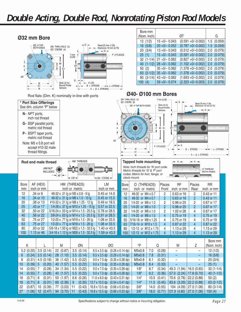
Rod fl ats (Dim. K) nominally in-line with ports
P 2 PLACES
7 mm(0.28)
Reed 25 mm (1.00)Electronic 19 mm (0.75)
K
Q
Q
L
ØDH TAP
E1
W
E1MZ ØT
G
B + STROKE
A + STROKE
M
ØN THRU HOLE (4)ØO C'BORE (8)
ØI
Slots (2) forRound Profile Sensors
Ø40- Ø100 mm Bores
O (THREADS) inch or metric #8-32 or M4 x 0.7 #8-32 or M4 x 0.7 1/4-20 or M6 x 1.0 1/4-20 or M6 x 1.0 1/4-20 or M6 x 1.0 1/4-20 or M6 x 1.0 5/16-18 or M8 x 1.25 7/16-14 or M10 x 1.5 1/2-13 or M12 x 1.75 1/2-13 or M12 x 1.75
PlacesFront
2222244444
RF inch or mm
0.63 or 160.63 or 160.98 or 250.98 or 251.02 or 260.75 or 190.75 or 190.87 or 221.13 or 291.13 or 29
PlacesRear
2222444444
RR inch or mm
0.43 or 110.43 or 110.67 or 170.67 or 170.67 or 170.75 or 190.75 or 190.87 or 221.13 or 291.13 or 29
R R
O THREAD BOTH ENDS
Tapped hole mounting
Boremm
12 16 20 25 32 40 50 63 80 100
HM (THREADS) inch or metric #8-32 x .31 lg or M5 x 0.8 - 9 lg #8-32 x .31 lg or M6 x 1.0 - 10 lg #10-32 x .31 lg or M8 x 1.25 - 12 lg 1/4-28 x .37 lg or M10 x 1.25 - 15 lg 5/16-24 x .50 lg or M14 x 1.5 - 20.5 lg 3/8-24 x .63 lg or M14 x 1.5 - 20.5 lg 1/2-20 x .77 lg or M18 x 1.5 - 26 lg 1/2-20 x .77 lg or M18 x 1.5 - 26 lg 5/8-18 x 1.00 lg or M22 x 1.5 - 32.5 lg 3/4-16 x 1.12 lg or M26 x 1.5 - 32.5 lg
LMinch or mm0.45 or 14.00.45 or 15.50.49 or 18.50.57 or 22.50.78 or 28.50.91 or 28.51.08 or 33.51.08 or 33.5
1.40 or 43.5 1.59 or 43.5
Bore mm 12 16 20 25 32 40 50 63 80 100
AF (HEX)inch or mm
.34 or 8 .34 or 10 .38 or 13 .43 or 17 .50 or 22 .56 or 22 .75 or 27 .75 or 27 .93 or 32 1.13 or 46
JAM NUT INCLUDED
HM THREADS
LMAF
Rod end male thread
Bore mm(Nom. Inch) 12 (1/2) 16 (5/8) 20 (3/4) 25 (1) 32 (1-1/4) 40 (1-1/2) 50 (2) 63 (2-1/2) 80 (3-1/4)100 (4)
ØT15 +0/– 0.043 (0.591 +0/–0.002)20 +0/– 0.052 (0.787 +0/–0.002)13 +0/– 0.043 (0.512 +0/–0.002)15 +0/– 0.043 (0.591 +0/–0.002)21 +0/– 0.062 (0.827 +0/–0.002)28 +0/– 0.062 (1.102 +0/–0.002)35 +0/– 0.062 (1.378 +0/–0.002)35 +0/– 0.062 (1.378 +0/–0.002)43 +0/– 0.062 (1.693 +0/–0.002)59 +0/– 0.074 (2.323 +0/–0.003)
G1.5 (0.059)1.5 (0.059)2.0 (0.079)2.0 (0.079)2.0 (0.079)2.0 (0.079)2.0 (0.079)2.0 (0.079)2.0 (0.079)2.0 (0.079)
Bore mm(Nom. Inch) 12 (1/2) 16 (5/8) 20 (3/4) 25 (1) 32 (1-1/4) 40 (1-1/2) 50 (2) 63 (2-1/2) 80 (3-1/4) 100 (4)
Z – – – –16.5 (0.65)17.8 (0.70)22.2 (0.88)22.2 (0.88)27.0 (1.06)27.0 (1.06)
W – – – – 49.3 (1.94) 57.0 (2.24) 70.6 (2.78) 83.6 (3.29) 104 (4.09) 121.9 (4.80)
Q7.0 (0.28)7.8 (0.31)8.1 (0.32)8.4 (0.33)8.7 (0.34)9.2 (0.36)10.5 (0.41)11.5 (0.45)14.0 (0.55)18.0 (0.71)
*PM5x0.8M5x0.8M5x0.8M5x0.8
1/8*1/8*1/4*1/4*3/8*3/8*
ØO 6.5 x 3.5 dp (0.26 x 0.14 dp) 6.5 x 3.5 dp (0.26 x 0.14 dp) 9.0 x 7.0 dp (0.35 x 0.28 dp) 9.0 x 7.0 dp (0.35 x 0.28 dp) 9.0 x 7.0 dp (0.35 x 0.28 dp) 9.0 x 7.0 dp (0.35 x 0.28 dp) 11.0 x 8.0 dp (0.43 x 0.31 dp) 13.7 x 10.5 dp (0.54 x 0.41 dp) 16.8 x 13.5 dp (0.66 x 0.53 dp) 16.8 x 13.5 dp (0.66 x 0.53 dp)
ØN 3.5 (0.14) 3.5 (0.14) 5.5 (0.22) 5.5 (0.22) 5.5 (0.22) 5.5 (0.22) 6.6 (0.26) 9 (0.35)11 (0.43)11 (0.43)
M 22 (0.87) 28 (1.10) 36 (1.42) 40 (1.57) 34 (1.34) 40 (1.57) 50 (1.97) 60 (2.36) 77 (3.03) 94 (3.70)
L3.5 (0.14)3.5 (0.14)4.5 (0.18)5 (0.20)7 (0.28)7 (0.28)8 (0.31)8 (0.31)10 (0.39)12 (0.47)
K 5.2 (0.20) 6 (0.24) 8 (0.31) 10 (0.39) 14 (0.55) 14 (0.55) 18 (0.71) 18 (0.71) 22 (0.87) 27 (1.06)
See page 37 for round profi le sensorsfeaturing surge suppression, polarity protection and dual output.
Reed 25 mm (1.00)Electronic 19 mm (0.75)
7 mm(0.28)
K
Q
Q
LE1W
P 2 PLACES
E1
MZ ØT
G
B + STROKEA + STROKE
M
ØN THRU HOLE (2)ØO C'BORE (4)
ØDH TAP
ØI
9 (.35)Slots (2) forRound ProfileSensors

Page 26
Global Series™Cylinders – Magnetic Piston
Specifi cations subject to change without notice or incurring obligation. 5-17-06
Dimensional Data
Q
L
G
P 2 PLACES
A + (2 x STROKE)
B + STROKE
ØT
Q
L + STROKE
KE1
E1
ØN THRU (2)ØO C'BORE (4)
E2
M
M–2
ØI
ØD H TAP BOTH ENDS
B2
7(.28)
Reed 25mm (1.00)Elect. 19mm (0.75)
Ø12 - Ø25 mm Bores
Sensors must be ordered separately.
See page 37.
WarningTHIS CYLINDER HAS A NON-ROTATING ROD. TO PREVENT INTERNAL DAMAGE HOLD ROD BY FLATS ONLY WHEN FULLY RETRACTED WHILE INSTALLING OR REMOVING ATTACHMENTS. DO NOT SCRATCH OR DENT SHAFT.
Bore size 12 16 20 25 32 40 50 63 80 100 Nonrotating rod accuracy ±2° ±1° ±1° ±1° ±0.8° ±0.8° ±0.8° ±0.8° ±0.8° ±0.8°
Model Code 'M'Bore
12 16 20 25 32 40 50 63 80 100
Hole Size NA (NA) 1.5 (.06) 1.5 (.06) 3.1 (.13) 3.1 (.13) 3.1 (.13) 4.0 (.16) 4.0 (.16) 6.3 (.25) 6.3 (.25)
Extended StrokeQ
8.9 (.35) 10.2 (.40) 12.1 (.48) 12.7 (.50) 12.7 (.50) 12.7 (.50) 13.2 (.52) 18.5 (.73) 14.0 (.55) 18.0 (.71)
Long StrokeB
38.8 (1.53) 41.2 (1.62) 49.6 (1.95) 55.5 (2.19) 56.8 (2.24) 55.5 (2.19) 59.3 (2.33) 64.6 (2.54) 69.5 (2.74) 76.7 (3.02)
A 45.8 (1.80) 48.2 (1.90) 58.6 (2.31) 65.5 (2.58) 70.8 (2.79) 69.5 (2.74) 75.3 (2.96) 80.6 (3.17) 89.5 (3.52)100.7 (3.96)
Stroke mm50, 75, 10050, 75, 100
75, 10075, 100125, 150125, 150125, 150125, 150125, 150125, 150
A––––
70.8 (2.79) 69.5 (2.74) 75.3 (2.96) 80.6 (3.17) 89.5 (3.52) 100.7 (3.96)
B––––
56.8 (2.24) 55.5 (2.19) 59.3 (2.33) 64.6 (2.54) 69.5 (2.74) 76.7 (3.02)
Q––––
12.7 (.50) 12.7 (.50) 13.2 (.52) 18.5 (.73) 14.0 (.55) 18.0 (.71)
Stroke mm––––
75, 10075, 10075, 10075, 10075, 10075, 100
Bore mm 12 16 20 25 32 40 50 63 80 100
H (Threads) x dp minimuminch or metric
#8-32 x .21dp M3 x 0.5 – 5 dp #8-32 x .21dp M4 x 0.7 – 5 dp #10-32 x .28 dp M5 x 0.8 – 7 dp 1/4-28 x .39 dp M6 x 1.0 – 10 dp 5/16-24 x .50 dp M8 x 1.25 – 12 dp 3/8-24 x .50 dp M8 x 1.25 – 12 dp 1/2-20 x .50 dp M10 x 1.5 – 12 dp 1/2-20 x .50 dp M10 x 1.5 – 12 dp 5/8-18 x .88 dp M16 x 2.0 – 22 dp 3/4-16 x .88 dp M20 x 2.5 – 22 dp
E2 23 (0.90) 27.2 (1.07) 31.2 (1.23) 36.9 (1.45) – – – – – –
E1 25 (0.98) 29 (1.14) 36 (1.42) 40 (1.57) 44.5 (1.75) 52 (2.05) 63.7 (2.51) 76.7 (3.02) 97.8 (3.85) 115.3 (4.54)
ØD 6 (0.236) 8 (0.315) 10 (0.394) 12 (0.472) 16 (0.630) 16 (0.630) 20 (0.787) 20 (0.787) 25 (0.984) 30 (1.181)
Stroke Range 5~30 (0.20~1.18) 5~30 (0.20~1.18) 5~50 (0.20~2.0) 5~50 (0.20~2.0) 5~50 (0.20~2.0) 5~50 (0.20~2.0) 10~50 (0.39~2.0) 10~50 (0.39~2.0) 10~50 (0.39~2.0) 10~50 (0.39~2.0)
Bore mm(Nom. Inch) 12 (1/2) 16 (5/8) 20 (3/4) 25 (1) 32 (1-1/4) 40 (1-1/2) 50 (2) 63 (2-1/2) 80 (3-1/4) 100 (4)
A44.4 (1.75)48.0 (1.89)55.0 (2.17) 57.0 (2.24)63.5 (2.50)64.0 (2.52)66.5 (2.62)68.0 (2.68)81.0 (3.19)94.5 (3.72)
B37.4 (1.47)41.0 (1.61)46.0 (1.81)47.0 (1.85)49.5 (1.95)50.0 (1.97)50.5 (1.99)52.0 (2.05)61.0 (2.40)70.5 (2.78)
ØI 31.5 (1.24) 37.1 (1.46) 47 (1.85) 51.3 (2.02) 58.9 (2.32) 69 (2.72) 84.9 (3.34) 101.8 (4.01) 129.8 (5.11) 153.9 (6.06)
Rod fl ats (Dim. K) nominally in-line with ports
Bore mm 12 16 20 25
B25 (.20)5 (.20)8 (.32)8 (.32)
Page 27
Double Acting, Double Rod, Nonrotating Piston Rod Models
Ø32 mm Bore
Specifi cations subject to change without notice or incurring obligation.5-8-06
A + (2 x STROKE)L + STROKE
Reed 25 mm (1.00)Electronic 19 mm (0.75)
7 mm(0.28)
K
Q
Q
LE1W
P 2 PLACES
E1
MZ ØT
G
B + STROKEM
ØN THRU HOLE (2)ØO C'BORE (4)
ØD H TAPBOTH ENDS
ØI
9 (.35)Slots (2) forRound Profile Sensors
Ø40- Ø100 mm BoresRod fl ats (Dim. K) nominally in-line with ports
* Port Size OfferingsSee dim. column “P” below
N– NPT ports, inch rod threadG– BSP parallel ports, metric rod threadP– BSPT taper ports, metric rod threadNote: M5 x 0.8 port will accept #10-32 male thread fi ttings.
Bore mm(Nom. Inch) 12 (1/2) 16 (5/8) 20 (3/4) 25 (1) 32 (1-1/4) 40 (1-1/2) 50 (2) 63 (2-1/2) 80 (3-1/4)100 (4)
ØT15 +0/– 0.043 (0.591 +0/–0.002)20 +0/– 0.052 (0.787 +0/–0.002)13 +0/– 0.043 (0.512 +0/–0.002)15 +0/– 0.043 (0.591 +0/–0.002)21 +0/– 0.062 (0.827 +0/–0.002)28 +0/– 0.062 (1.102 +0/–0.002)35 +0/– 0.062 (1.378 +0/–0.002)35 +0/– 0.062 (1.378 +0/–0.002)43 +0/– 0.062 (1.693 +0/–0.002)59 +0/– 0.074 (2.323 +0/–0.003)
G1.5 (0.059)1.5 (0.059)2.0 (0.079)2.0 (0.079)2.0 (0.079)2.0 (0.079)2.0 (0.079)2.0 (0.079)2.0 (0.079)2.0 (0.079)
Bore mm(Nom. Inch) 12 (1/2) 16 (5/8) 20 (3/4) 25 (1) 32 (1-1/4) 40 (1-1/2) 50 (2) 63 (2-1/2) 80 (3-1/4) 100 (4)
Z – – – –16.5 (0.65)17.8 (0.70)22.2 (0.88)22.2 (0.88)27.0 (1.06)27.0 (1.06)
W – – – – 49.3 (1.94) 57.0 (2.24) 70.6 (2.78) 83.6 (3.29) 104 (4.09) 121.9 (4.80)
Q7.0 (0.28)7.8 (0.31)8.1 (0.32)8.4 (0.33)8.7 (0.34)9.2 (0.36)10.5 (0.41)11.5 (0.45)14.0 (0.55)18.0 (0.71)
*PM5x0.8M5x0.8M5x0.8M5x0.8
1/8*1/8*1/4*1/4*3/8*3/8*
ØO 6.5 x 3.5 dp (0.26 x 0.14 dp) 6.5 x 3.5 dp (0.26 x 0.14 dp) 9.0 x 7.0 dp (0.35 x 0.28 dp) 9.0 x 7.0 dp (0.35 x 0.28 dp) 9.0 x 7.0 dp (0.35 x 0.28 dp) 9.0 x 7.0 dp (0.35 x 0.28 dp) 11.0 x 8.0 dp (0.43 x 0.31 dp) 13.7 x 10.5 dp (0.54 x 0.41 dp) 16.8 x 13.5 dp (0.66 x 0.53 dp) 16.8 x 13.5 dp (0.66 x 0.53 dp)
ØN 3.5 (0.14) 3.5 (0.14) 5.5 (0.22) 5.5 (0.22) 5.5 (0.22) 5.5 (0.22) 6.6 (0.26) 9 (0.35)11 (0.43)11 (0.43)
M 22 (0.87) 28 (1.10) 36 (1.42) 40 (1.57) 34 (1.34) 40 (1.57) 50 (1.97) 60 (2.36) 77 (3.03) 94 (3.70)
L3.5 (0.14)3.5 (0.14)4.5 (0.18)5 (0.20)7 (0.28)7 (0.28)8 (0.31)8 (0.31)10 (0.39)12 (0.47)
K 5.2 (0.20) 6 (0.24) 8 (0.31) 10 (0.39) 14 (0.55) 14 (0.55) 18 (0.71) 18 (0.71) 22 (0.87) 27 (1.06)
HM (THREADS) inch or metric #8-32 x .31 lg or M5 x 0.8 - 9 lg #8-32 x .31 lg or M6 x 1.0 - 10 lg #10-32 x .31 lg or M8 x 1.25 - 12 lg 1/4-28 x .37 lg or M10 x 1.25 - 15 lg 5/16-24 x .50 lg or M14 x 1.5 - 20.5 lg 3/8-24 x .63 lg or M14 x 1.5 - 20.5 lg 1/2-20 x .77 lg or M18 x 1.5 - 26 lg 1/2-20 x .77 lg or M18 x 1.5 - 26 lg 5/8-18 x 1.00 lg or M22 x 1.5 - 32.5 lg 3/4-16 x 1.12 lg or M26 x 1.5 - 32.5 lg
LMinch or mm0.45 or 14.00.45 or 15.50.49 or 18.50.57 or 22.50.78 or 28.50.91 or 28.51.08 or 33.51.08 or 33.5
1.40 or 43.5 1.59 or 43.5
Bore mm 12 16 20 25 32 40 50 63 80 100
AF (HEX)inch or mm
.34 or 8 .34 or 10 .38 or 13 .43 or 17 .50 or 22 .56 or 22 .75 or 27 .75 or 27 .93 or 32 1.13 or 46
JAM NUT INCLUDED
HM THREADS
LM + STROKELMAF
Rod end male thread R R
O THREAD BOTH ENDS
Note: Inch threads for 'N' port code.Metric threads for 'G' & 'P' port codes. Metric for foot, fl ange, or clevis mount.
Tapped hole mounting
Boremm
12 16 20 25 32 40 50 63 80 100
O (THREADS) inch or metric #8-32 or M4 x 0.7 #8-32 or M4 x 0.7 1/4-20 or M6 x 1.0 1/4-20 or M6 x 1.0 1/4-20 or M6 x 1.0 1/4-20 or M6 x 1.0 5/16-18 or M8 x 1.25 7/16-14 or M10 x 1.5 1/2-13 or M12 x 1.75 1/2-13 or M12 x 1.75
PlacesFront
2222244444
RF inch or mm
0.63 or 160.63 or 160.98 or 250.98 or 251.02 or 260.75 or 190.75 or 190.87 or 221.13 or 291.13 or 29
PlacesRear
2222444444
RR inch or mm
0.43 or 110.43 or 110.67 or 170.67 or 170.67 or 170.75 or 190.75 or 190.87 or 221.13 or 291.13 or 29
L + STROKE
A + (2 x STROKE)
ØN THRU HOLE (4)ØO C'BORE (8)
P 2 PLACES
7 mm (0.28)
Reed 25 mm (1.00)Electronic 19 mm (0.75)
K
Q
Q
L
ØD H TAP BOTH ENDS
E1
W
E1MZ ØT
G
B + STROKEM
ØI
Slots (2) forRound Profile Sensors

Page 28
Global Series™Cylinders – Magnetic Piston
Note - Chart dimensions are shown as mm (inches)
Dimensional Data
Specifi cations subject to change without notice or incurring obligation.
Adjustable Extend Stroke Cylinders – Fabco-Air's popular Dial-A-Stroke® adjustment assembly is now available on Global Series™ Cylinders to provide a rugged, precision adjustment of the cylinder extend stroke.Cylinders are offered in double acting models in bore sizes of 32mm through 100mm with full stroke adjustment.Magnetic pistons are included for use with any of the electronic or reed sensors. Sensors must be ordered separately. See page 37.Operator Safety –The stop tube, adjustment nut with skirt, and minimum clearances combine to eliminate pinch points.
Construction –The stop tube is black anodized aluminum – the adjustment nut is blackened steel with a black anodized aluminum skirt – the stop fl ange is red anodized aluminum: all for corrosion resistance and appearance. The adjustment nut, steel for long life, includes a lock screw with a plastic plug so the adjustment nut can be locked in place without damaging the threads. Precision adjustment is achieved with fi ne pitch threads on the adjustment rod. The stop fl ange is mounted on the end of the adjustment rod so the nut will not come off.Adjustment – Adjustment settings are simplifi ed by the convenient scale markings. Bores 32 and 40 have a 1/2-20 thread giving .050" (1.3mm) adjustment per nut revolution. Bores 50 and larger have a 3/4-16 thread giving .063" (1.6mm) adjustment per revolution.
Precision Stroke Adjustment Emphasizing Operator Safety
5-17-06
How to Order (See page 9 - model codes A & AK; see page 29 - mounting codes.)
Example 1: To order a 63mm bore, 75mm stroke unit with Dial-a-Stroke®, NPT ports, and rod end tap mount, specify
Model No. GND–AA063–075D
Example 2: Also available with non-rotating rod; use body length 'B' dimension from page 26, tapped hole mounting information from page 27 and insert the non-rotating rod Code 'K' in model number. To order 63mm bore, 75mm stroke, nonrotating rod, with Dial-a-Stroke®, NPT ports, and ISO fl ange specify
Model No. GND–AKG063–075DNote – When ordering units with fl ange or foot mounts, the rod stickout (Dim. "L") increases per dimension on pages 31 or 32.
Full stroke adjustment on all strokes.
STROKE mm
K14 (0.55)14 (0.55)17 (0.67)17 (0.67)22 (0.87)27 (1.06)
ØI 58.9 (2.32) 69.0 (2.72) 84.9 (3.34) 101.8 (4.01) 129.8 (5.11) 153.9 (6.06)
inch or metric 5/16-24 x .52 dp M8 x 1.25 – 13 dp 3/8-24 x .72 dp M8 x 1.25 – 13 dp 1/2-20 x .69 dp M10 x 1.5 – 12 dp 1/2-20 x .69 dp M10 x 1.5 – 12 dp 5/8-18 x .96 dp M16 x 2.0 – 21dp 3/4-16 x 1.06 dp M20 x 2.5 – 30 dp
E1 44.5 (1.75) 52 (2.05) 63.7 (2.51) 76.7 (3.02) 97.8 (3.85) 115.3 (4.54)
ØD 16 (0.630) 16 (0.630) 20 (0.787) 20 (0.787) 25 (0.984) 30 (1.181)
75, 100, 125, 150 B
47.8 (1.88)55.5 (2.19)59.3 (2.33)64.6 (2.54)69.5 (2.74)76.7 (3.02)
15, 25, 50 B
40.5 (1.59)50.0 (1.97)50.5 (1.99)52.0 (2.05)61.0 (2.40)70.5 (2.78)
BORE mm(Nom. Inch) 32 (1-1/4) 40 (1-1/2) 50 (2) 63 (2-1/2) 80 (3-1/4) 100 (4)
L7 (0.28)7 (0.28)8 (0.31)8 (0.31)10 (0.39)12 (0.47)
H (THREADS)
M 34 (1.34) 40 (1.57) 50 (1.97) 60 (2.36) 77 (3.03) 94 (3.70)
Magnetic piston is a standard feature. Apply sensors (ordered separately) to dovetail or round slots for mid-stroke and end-of-stroke sensing.

Page 29
Dial-A-Stroke® Adjustable Extend Stroke Models
Note: Inch threads for 'N' port code.Metric threads for 'G' & 'P' port codes. Metric for foot, fl ange, or clevis mount.
▼
Also availablewith
Nonrotating rod.See page 28example 2.
Specifi cations subject to change without notice or incurring obligation.
Ø32 - Ø100 mm Bores
6-2-06
7 mm (0.28)
Q Q
ØD
L B + STROKE
P 2 PLACES
T
R + (2 x STROKE)
STROKE
ØS
Reed 25 mm (1.00)Electronic19 mm (0.75)
KFLATS
Z M E1
M
E1
H THREADS
ØI
W
Standard mounting – Code "A" Tapped Holes 4 places useable at rod end only. Also includes 2 thru holes ØN w/c'bore ØOOptional mounting – See “How to Order” note page 28. Code "E" Front Flange Code "G" ISO Front Flange Code "L" Foot MountNote! ! Use caution when mounting to avoid creating pinch points with other parts of your machinery
Sensors must be ordered separately.
See page 37.
* Port Size OfferingsSee dim. column “P” below
N– NPT ports, inch rod threadG– BSP parallel ports, metric rod threadP– BSPT taper ports, metric rod thread
O (THREADS) inch or metric 1/4-20 or M6 x 1.0 1/4-20 or M6 x 1.0 5/16-18 or M8 x 1.25 7/16-14 or M10 x 1.5 1/2-13 or M12 x 1.75 1/2-13 or M12 x 1.75
Tapped hole mounting
RFinch or mm
0.67 or 170.75 or 190.75 or 190.87 or 221.13 or 291.13 or 29
Bore mm 32 40 50 63 80 100
RF O THREAD
HM (THREADS) inch or metric 5/16-24 x .50 lg or M14 x 1.5 - 20.5 lg 3/8-24 x .63 lg or M14 x 1.5 - 20.5 lg 1/2-20 x .77 lg or M18 x 1.5 - 26 lg 1/2-20 x .77 lg or M18 x 1.5 - 26 lg 5/8-18 x 1.00 lg or M22 x 1.5 - 32.5 lg 3/4-16 x 1.12 lg or M26 x 1.5 - 32.5 lg
LMinch or mm0.78 or 28.50.91 or 28.51.08 or 33.51.08 or 33.51.40 or 43.51.59 or 43.5
Rod end male thread
AF (HEX) inch or mm .50 or 22 .56 or 22 .75 or 27 .75 or 27 .93 or 32 1.13 or 46
JAM NUT INCLUDED
HM THREADS
LMAF
ØN 5.5 (0.22) 5.5 (0.22) 6.6 (0.26) 9 (0.35) 11 (0.43) 11 (0.43)
ØO 9.0 x 7.0 dp (0.35 x 0.28 dp) 9.0 x 7.0 dp (0.35 x 0.28 dp) 11.0 x 8.0 dp (0.43 x 0.31 dp) 13.7 x 10.5 dp (0.54 x 0.41 dp) 16.8 x 13.5 dp (0.66 x 0.53 dp) 16.8 x 13.5 dp (0.66 x 0.53 dp)
*P1/8*1/8*1/4*1/4*3/8*3/8*
Q 8.7 (0.34) 9.2 (0.36) 10.5 (0.41) 11.5 (0.45) 14.0 (0.55) 18.0 (0.71)
R 41.1 (1.62) 41.1 (1.62) 53.6 (2.11) 52.6 (2.07) 56.6 (2.23) 65.1 (2.56)
ØS 38 (1.5) 38 (1.5) 50.8 (2.0) 50.8 (2.0) 50.8 (2.0) 50.8 (2.0)
T 7.6 (.30) 7.6 (.30) 12.0 (.47) 11.0 (.43) 15.0 (.59) 15.0 (.59)
W49.3 (1.94)57.0 (2.24)70.6 (2.78)83.6 (3.29)104 (4.09)121.9 (4.80)
Z16.5 (0.65)17.8 (0.70)22.2 (0.88)22.2 (0.88)27.0 (1.06)27.0 (1.06)
Bore mm(Nom. Inch) 32 (1-1/4) 40 (1-1/2) 50 (2) 63 (2-1/2) 80 (3-1/4) 100 (4)
BORE mm 32 40 50 63 80 100
15, 25, 50 75, 100, 125, 150Q
12.7 (0.50) 12.7 (0.50) 13.2 (0.52) 18.5 (0.73) 14.0 (0.55) 18.0 (0.71)
STROKE mm

Page 30
Global Series™Cylinders
E1
E1
CXCZCW RR
CU
Ø Pin
LTLG
N BOLT 2PLACES
– Rear Clevis Mount
Rear Clevis Mount Dimensions
Ø32 - Ø100 mm Bores
Bore mm121620253240506380100
N BOLTM4x0.7M4x0.7M6x1.0M6x1.0M6x1.0M6x1.0M8x1.25M10x1.5M12x1.75M12x1.75
Note: Pin diameter will be inch size for cylinders with port code 'N' and mm size for cylinders with port code 'G' or 'P'.
CW RR
CU
E1
CX
CZ
E1
Ø Pin
LTLG
N BOLT 4 PLACES
Specifi cations subject to change without notice or incurring obligation.
Note: All clevis mounts attach to cylinder body with metric
size socket cap screws
Ø12 - Ø25 mm Bores
5-17-06
CU7.0 (0.28)10 (0.39)12 (0.47)14 (0.55)14 (0.55)14 (0.55)20 (0.79)20 (0.79)27 (1.07)31 (1.22)
CZ10 (0.39)12 (0.47)16 (0.63)20 (0.79)36 (1.42)36 (1.42)44 (1.73)44 (1.73)56 (2.20)64 (2.52)
LT 5 (0.20) 5 (0.20) 5 (0.20) 5 (0.20) 6 (0.24) 8 (0.31) 8 (0.31) 10 (0.39) 11 (0.43) 14 (0.55)
LG 2.8 (0.11) 2.8 (0.11) 4.0 (0.16) 4.0 (0.16) 4.0 (0.16) 4.0 (0.16) 5.0 (0.20) 6.0 (0.24) 7.0 (0.28) 7.0 (0.28)
RR6.0 (0.24)6.0 (0.24)9.0 (0.35)10 (0.39) 10 (0.39)10 (0.39)14 (0.55)14 (0.55)18 (0.71)22 (0.87)
E1 25 (0.98) 29 (1.14) 36 (1.42) 40 (1.57) 44.5 (1.75) 52 (2.05) 63.7 (2.51) 76.7 (3.02) 97.8 (3.85) 115.3 (4.54)
Bore mm(Nom. Inch)
12 (1/2)16 (5/8)20 (3/4)25 (1)32 (1-1/4)40 (1-1/2)50 (2)63 (2-1/2)80 (3-1/4)100 (4)
CW14 (0.55)15 (0.59)18 (0.71)20 (0.79)20 (0.79)22 (0.87)28 (1.10)30 (1.18)38 (1.50)45 (1.77)
CX 5.3 (0.21) 6.8 (0.27) 8.3 (0.33)10.3 (0.41)18.3 (0.72)18.3 (0.72)22.3 (0.88)22.3 (0.88)28.3 (1.11)32.3 (1.27)
Ø Pin Nominal mm or inch 5 or .187 5 or .187 8 or .312 10 or .375 10 or .375 10 or .375 14 or .500 14 or .500 18 or .750 22 or .875

Page 31
LXLZ
L
LY
N BOLT 4 PLACES
LH
LD 4 PLACES
X X
LT
Y Y
LGLT
L+StrokeDouble Rod
– Foot Mounts
Specifi cations subject to change without notice or incurring obligation.
Bore mm121620253240506380100
N BOLTM4x0.7M4x0.7M6x1.0M6x1.0M6x1.0M6x1.0M8x1.25M10x1.5M12x1.75M12x1.75
Foot Mount Dimensions
LD 4 PLACES
LH
LY
X XY Y
L
LX
LZ
LG
N BOLT 4 PLACES
LT
LT
Note: All feet attach to cyl-inder body with metric size
socket cap screws
Ø32 - Ø100 mm Bores
Ø12 - Ø25 mm Bores
5-17-06
Bore mm(Nom. Inch)12 (1/2)16 (5/8)20 (3/4)25 (1)32 (1-1/4)40 (1-1/2)50 (2)63 (2-1/2)80 (3-1/4)100 (4)
Y4.5 (0.18)5.0 (0.20)5.8 (0.23)5.8 (0.23)5.8 (0.23)7.0 (0.28)8.0 (0.31)9.0 (0.35)11.0 (0.43)12.5 (0.49)
X8 (0.31)8 (0.31)9.2 (0.36)10.7 (0.42)11.2 (0.44)11.2 (0.44)14.7 (0.58)16.2 (0.64)19.5 (0.77)23 (0.91)
LD4.5 (0.18)4.5 (0.18)6.6 (0.26)6.6 (0.26)6.6 (0.26)6.6 (0.26)9.0 (0.35)11 (0.43)13 (0.51)13 (0.51)
LG2.8 (0.11)2.8 (0.11)4.0 (0.16)4.0 (0.16)4.0 (0.16)4.0 (0.16)5.0 (0.20)6.0 (0.24)7.0 (0.28)7.0 (0.28)
LT2 (0.08)2 (0.08)3.2 (0.13)3.2 (0.13)3.2 (0.13)3.2 (0.13)3.2 (0.13)3.2 (0.13)4.5 (0.18)6.0 (0.24)
L13.5 (0.53)13.5 (0.53)14.5 (0.57)15 (0.59)17 (0.67)17 (0.67)18 (0.71)18 (0.71)20 (0.79)22 (0.87)
LZ44 (1.73)48 (1.89)62 (2.44)66 (2.60)71 (2.80)78 (3.07)95 (3.74)113 (4.45)140 (5.51)162 (6.38)
LX34 (1.34)38 (1.50)48 (1.89)52 (2.05) 57 (2.24)64 (2.52)79 (3.11)95 (3.74)118 (4.65)137 (5.39)
LH17 (0.67)19 (0.75)24 (0.94)26 (1.02)30 (1.18)33 (1.30)39 (1.54)46 (1.81)59 (2.32)71 (2.80)
LY29.5 (1.16)33.5 (1.32)42.0 (1.65)46.0 (1.81)57.0 (2.24)64.0 (2.52)78.0 (3.07)91.5 (3.60)114 (4.49)136 (5.35)

Page 32
Global Series™Cylinders
Flange Mount Dimensions
5-17-06
Note: All fl anges attach to cylinder body with metric size fl at head socket screws
Front Flange Ø32 - Ø100 mm Bores
D 2 PlacesFXFZ
L
FT
FV
N Bolt 2 Places
Front Flange Ø12 - Ø25 mm Bores
LFTFX
FZ
FY FV
FD 4 Places
N Bolt 4 Places
FT FXFZ
FYFV
FD 4 Places
N Bolt 4 Places
Rear Flange Ø32 - Ø100 mm Bores
FT
FV
FD 2 Places N Bolt 2 Places
FXFZ
Rear Flange Ø12 - Ø25 mm Bores
– Flange Mounts
Specifi cations subject to change without notice or incurring obligation.
Bore mm(Nom. Inch)12 (1/2)16 (5/8)20 (3/4)25 (1)32 (1-1/4)40 (1-1/2)50 (2)63 (2-1/2)80 (3-1/4)100 (4)
Interchange (Non-ISO) Flange DimensionsCommon Dimensions
FZ 55 (2.17) 55 (2.17) 60 (2.36) 64 (2.52) 65 (2.56) 72 (2.83) 89 (3.50) 108 (4.25) 134 (5.28) 154 (6.06)
FV25 (0.98)30 (1.18)39 (1.54)42 (1.65)48 (1.89)54 (2.13)67 (2.64)80 (3.15)99 (3.90)117 (4.61)
FX45 (1.77)45 (1.77)48 (1.89)52 (2.05)56 (2.20)62 (2.44)76 (2.99)92 (3.62)116 (4.57)136 (5.35)
FY––––
34 (1.34)40 (1.57)50 (1.97)60 (2.36)77 (3.03) 94 (3.70)
FD4.5 (0.18)4.5 (0.18)6.6 (0.26)6.6 (0.26)5.5 (0.22)5.5 (0.22)6.6 (0.26)9 (0.35)11 (0.43)11 (0.43)
N BoltM4 x 0.7M4 x 0.7M6 x 1.0M6 x 1.0M6 x 1.0M6 x 1.0M8 x 1.25M10 x 1.5M12 x 1.75M12 x 1.75
L8.0 (0.31)8.0 (0.31)6.5 (0.26)7.0 (0.28) 9.0 (0.35)9.0 (0.35)9.0 (0.35)9.0 (0.35)9.0 (0.35)11 (0.43)
FT5.5 (0.22)5.5 (0.22)8 (0.31)8 (0.31)8 (0.31)8 (0.31)9 (0.35)9 (0.35)11 (0.43)11 (0.43)
ISO Rectangular Flange Dimensions
FD5.5 (0.22)5.5 (0.22)6.6 (0.26)6.6 (0.26)7 (0.28)9 (0.35)9 (0.35)9 (0.35)12 (0.47)14 (0.55)
FY––––
32 (1.26)36 (1.42)45 (1.77)50 (1.97)63 (2.48)75 (2.95)
FX40 (1.57)40 (1.57)50 (1.97)50 (1.97)64 (2.52)72 (2.83)90 (3.54)100 (3.94)126 (4.96)150 (5.91)
FV25 (0.98)30 (1.18)39 (1.54)42 (1.65)48 (1.89)54 (2.13)67 (2.64)80 (3.15)99 (3.90)117 (4.61)
FZ50 (1.97)50 (1.97)62 (2.44)62 (2.44)76 (2.99)88 (3.47)106 (4.17)116 (4.57)150 (5.91)178 (7.01)
Bore mm 12 16 20 25 32 40 50 63 80 100

Page 33
Boss Mount Dimensions
Rear Boss Ø32 - Ø100 mm Bores Front Boss Ø32 - Ø100 mm Bores
Front Boss Ø12 - Ø25 mm BoresRear Boss Ø12 - Ø25 mm Bores
5-12-06
G
ØTØT
G
G
ØT
G
ØT
– Front & Rear Boss Mounts
Specifi cations subject to change without notice or incurring obligation.
Bore mm(Nom. Inch)12 (1/2)16 (5/8)20 (3/4)25 (1)32 (1-1/4)40 (1-1/2)50 (2)63 (2-1/2)80 (3-1/4)100 (4)
G1.5 (0.059)1.5 (0.059)2.0 (0.079)2.0 (0.079)2.0 (0.079)2.0 (0.079)2.0 (0.079)2.0 (0.079)2.0 (0.079)2.0 (0.079)
ØT15 +0/– 0.043 (0.591 +0/–0.002)20 +0/– 0.052 (0.787 +0/–0.002)13 +0/– 0.043 (0.512 +0/–0.002)15 +0/– 0.043 (0.591 +0/–0.002)21 +0/– 0.062 (0.827 +0/–0.002)28 +0/– 0.062 (1.102 +0/–0.002)35 +0/– 0.062 (1.378 +0/–0.002)35 +0/– 0.062 (1.378 +0/–0.002)43 +0/– 0.062 (1.693 +0/–0.002)59 +0/– 0.074 (2.323 +0/–0.003)

Page 34
Global Series™Cylinders
Specifi cations subject to change without notice or incurring obligation.
Ordering Example – Global Series, BSPT ports, with single magnetic pis-ton, 63mm bore, dual strokes of 75 and 100mm, and male rod thread.
The Model Number is: GPD – SA063 – 075/100D – M – XC11
When magnets and bumpers are required in both forward and rear cylinders, and tapped holes are required at cap end, order as
GPDD – SA063 – 075 – B/100D – B – M – XC12
Tandem cylinders are generally used when three distinct rod positions are required. Two cylinders are assembled tip-to-tail with bolts threaded into the rear tapped mounting holes of the forward cylinder.
Using cylinders with two different strokes (the shorter located on the rear cylinder), enables a single rod to be extended to a positive mid-position or to full extension.
To order specify the desired strokes with a slash between the 3-digit stroke codes, then follow model number with option suffi x –XC11 or –XC12
Note: More than three positions can be obtained by assembling multiple cylinders together. Please consult the factory for these special requirements.
T1T2
T1
T2Consult factory to
confirm total body length
When a single magnetic piston is ordered, it is applied in the forward cylinder
5-12-06
Tandem Cylinders – Option XC11 & XC12Note: Available double acting only
XC11 Mounting: Code 'A' tapped holes at rod end. Code 'E' or 'G' fl ange optional
Consult factory to confirm total body length
Back-to-back cylinders are for use where three or four rod positions are required. Two cylinders are assembled back-to-back with bolts threaded into tapped end mounting holes.
Different strokes on each cylinder enable having four positive stop positions when the units are mounted at the rod ends.
Back-to-back cylinders provide independent piston rods on each end of the unit.
To order specify the desired strokes with a slash between the 3-digit stroke codes, then follow model number with option suffi x –XC10
Back-to-Back Cylinders – Option XC10Note 1: Available double acting onlyNote 2: Magnetic piston body style "D"includes magnet in both cylinder sections
1. Ordering Example – Global Series, NPT ports, magnetic piston, 40mm bore, dual strokes of 30 and 50mm, bumpers both ends and male rod ends.
The Model Number is: GND – SB040 – 030 – B – M / – 050D – B – M – XC10
2. A non-rotating rod can be fi tted to one section. The position of "K" model code determines the stroke of the non-rotating rod cylinder section.
Example: GNN – SKB040 – 030/050D – XC10
"S" Indicates 30 stroke single rod "K" indicates 50 stroke non-rotating rod
Tie bolts are used in all holes

Page 35
– Cylinder Options and Universal Seal Kits
Universal Seal Kits – For single and double rod cylinders and adjustable stroke models. Nonrotating rod seals are available separately. Seals for options are available on request.
Adjustable Retract Stroke – Option RS
Viton Seals – Option V
An adjusting screw with a thread sealing locknut mounted in a thick rear cover provides a simple, yet rugged adjustment of the cylinder stroke in the retract direction. The fi ne thread of the adjusting screw provides precision adjustment.Bores 20, 25 and 32mm have a 5/16-24 thread giving .042" (1.1mm) adjustment per revolution. Bores 40 thru 100mm have a 1/2-20 thread giving .050" (1.3mm) adjustment.
The adjustable retract stroke option is available on 20mm bores and larger for any stroke. Standard adjustment is up to and including 25mm.
For over 25mm adjustment specify adjustment length after the option designation RS.
Example: for 50mm adjustment the option designation becomes RS-50
Thread sealing locknut
Adjusting screw
Available on Bores 20mm and Larger
For elevated temperatures from –26C° to 204C°(-15F° to +400° F) or for compatibility with hostile media. Consult engineering for compatibility information.
Specifi cations subject to change without notice or incurring obligation.9-24-04
Pressure applied to pistonOpen to atmosphere
1
3
2
3 Position Application
Pressure applied to pistonOpen to atmosphere
1
4
3
2
4 Position Application
Seal Kit Non-Rotating Rod Seal
Buna N G12 - SK G16 - SK G20 - SK G25 - SK G32 - SK G40 - SK G50 - SK G63 - SK G80 - SK G100 - SK
Bore121620253240506380100
Viton G12 - SKV G16 - SKV G20 - SKV G25 - SKV G32 - SKV G40 - SKV G50 - SKV G63 - SKV G80 - SKV G100 - SKV

Page 36
Global Series™Cylinders
U 7.0 (0.27) 10.0 (0.39) 11.5 (0.45) 14.0 (0.55) 14.0 (0.55) 14.0 (0.55) 20.0 (0.79) 20.0 (0.79) 27.0 (1.06) 31.0 (1.22)
X 5.3 (0.21) 6.6 (0.26) 8.3 (0.33) 10.3 (0.41) 18.4 (0.72) 18.4 (0.72) 22.4 (0.88) 22.4 (0.88) 28.4 (1.12) 32.4 (1.28)
Z 10 (0.39) 12 (0.47) 16 (0.63) 20 (0.78) 36.6 (1.44) 36.6 (1.44) 44.5 (1.75) 44.5 (1.75) 55.6 (2.19) 63.5 (2.50)
P 14 (0.55) 16 (0.63) 21 (0.83) 25 (0.98) 41 (1.61) 41 (1.61) 50 (1.97) 50 (1.97) 62.5 (2.46) 70.6 (2.78)
R 6.3 (0.25) 12.0 (0.47) 10.3 (0.41) 12.8 (0.50) 12.0 (0.47) 12.0 (0.47) 16.0 (0.63) 16.0 (0.63) 21.0 (0.83) 24.0 (0.95)
E 10 (0.39) 12 (0.47) 16 (0.63) 20 (0.78) 22 (0.87) 22 (0.87) 28 (1.10) 28 (1.10) 38 (1.50) 44 (1.73)
Bore mm(Nom. Inch)12 (1/2)16 (5/8)20 (3/4)25 (1)32 (1-1/4)40 (1-1/2)50 (2)63 (2-1/2)80 (3-1/4)100 (4)
A1 6.0 (0.24) 6.0 (0.24) 6.0 (0.24) 8.0 (0.31) 16.0 (0.63) 16.0 (0.63) 20.0 (0.79) 20.0 (0.79) 23.0 (0.91) 24.0 (0.95)
L16 (0.63)21 (0.83)25 (0.98)30 (1.18)30 (1.18)30 (1.18)40 (1.57)40 (1.57)50 (1.97)55 (2.17)
A 21.5 (0.85) 28.0 (1.10) 34.0 (1.34) 41.0 (1.61) 42.0 (1.65) 42.0 (1.65) 56.0 (2.20) 56.0 (2.20) 71.0 (2.80) 79.0 (3.11)
32(1.26)
34(1.34)
8.5(.33)
9.8(.39)
Sensor
Pigtail
1, 2 or 5
Meter Cable
– Accessories
Rod Clevis –
Specifi cations subject to change without notice or incurring obligation.
To order a Rod Eye use the Prefi x RE– followed by the thread size.
Example: For a 25mm bore cylinder the inch rod threads are 1/4-28. The Rod Eye Part Number is RE–1/4-28For #8-32 size, follow with –12 or –16 for bore. Example: RE-8-32-16
Rod Eye –
X
A1
UL
A
M
Ø Hole
Rad. R
Z
A1
UL
A
M
Ø PIN
E
X P Z
R
Note: Pin diameter will be inch size for items with inch threadand mm size for items with metric thread.
3-3-10
8 mm Female Cordsetsfor Quick Disconnect Sensors
Brown
BlueBlack
Blue (–)
Brown (+)Black
Male Connector on Sensor Female Connector on Cordset
L 16 (0.63) 25 (0.98) 25 (0.98) 30 (1.18) 30 (1.18) 30 (1.18) 40 (1.57) 40 (1.57) 50 (1.97) 55 (2.17)
R 6.3 (0.25) 12.0 (0.47) 10.3 (0.41) 12.8 (0.50) 12.0 (0.47) 12.0 (0.47) 16.0 (0.63) 16.0 (0.63) 21.0 (0.83) 24.0 (0.95)
A21.5 (0.85)32.0 (1.26)34.0 (1.34)41.0 (1.61)42.0 (1.65)42.0 (1.65)56.0 (2.20)56.0 (2.20)71.0 (2.80)79.0 (3.11)
Z 9.7 (0.38) 11.2 (0.44) 16 (0.63) 19 (0.75) 22 (0.87) 22 (0.87) 27 (1.06) 27 (1.06) 38 (1.50) 44.5 (1.75)
X4.7 (0.18)6.2 (0.24)7.7 (0.30)9.7 (0.38) 17.6 (0.69)17.6 (0.69)21.6 (0.85)21.6 (0.85)27.6 (1.08)31.6 (1.24)
U 7.0 (0.27) 14.0 (0.55) 11.5 (0.45) 14.0 (0.55) 14.0 (0.55) 14.0 (0.55) 20.0 (0.79) 20.0 (0.79) 27.0 (1.06) 31.0 (1.22)
Bore mm(Nom. Inch)12 (1/2)16 (5/8)20 (3/4)25 (1)32 (1-1/4)40 (1-1/2)50 (2)63 (2-1/2)80 (3-1/4)100 (4)
To order a Rod Clevis use the Prefi x RC– fol-lowed by the thread size. Example: For a 63mm bore cylinder the metric threads are M18 x 1.5. The Rod Clevis Part Number is RC–M18x1.5 For #8-32 size, follow with –12 or –16 for bore. Example: RC-8-32-12
CordsetDescription
1 Meter, 3 Pin 2 Meters, 3- Pin5 Meters, 3- Pin
Part No.CFC-1MCFC-2MCFC-5M
M Threadsinch or metric
#8-32 or M5 x 0.8 #8-32 or M6 x 1.0 #10-32 or M8 x 1.25 1/4-28 or M10 x 1.25 5/16-24 or M14 x 1.5 3/8-24 or M14 x 1.5 1/2-20 or M18 x 1.5 1/2-20 or M18 x 1.5 5/8-18 or M22 x 1.5 3/4-16 or M26 x 1.5
Bore 12 16 20 25 32 40 50 63 80 100
Ø Hole, Ø Pin Nominal.187 or 5.187 or 5.312 or 8.375 or 10.375 or 10.375 or 10.500 or 14.500 or 14.750 or 18.875 or 22
A1 6.0 (0.24) 6.0 (0.24) 6.0 (0.24) 8.0 (0.31) 14.0 (0.55) 14.0 (0.55) 18.0 (0.71) 18.0 (0.71) 21.0 (0.83) 21.0 (0.83)

Page 37
NEW – Low Profi le Sensors for Magnetic Piston Cylinders
Specifi cations subject to change without notice or incurring obligation.12-11-08
• Encased in a plastic housing, dovetail style sensors are corrosion resistant. • 60° wire outlet allows close mounting.• Sensors are mounted in dovetail slots in the wall of the cylinder and are actuated by a magnetic piston. Magnetic pistons are specifi ed with Body Code "D" in the Global Series™ Cylinder model number. • Two types of sensors are offered: Reed Switches and Electronic Sensors. Sensors must be ordered separately from the tables below. • Each sensor is furnished complete with a set screw for secure installation.• Mounting clamp included with 949-200-xxx models for 3/8" dovetail.
1 Insert the mounting clamp into one of the dovetail slots and slide it to the approximate location desired. Position the sensor with its set screw facing the mounting clamp.
Sensor (Reed Switch shown)
Note*: Quick Disconnect styles are supplied with 6 inch pigtail with male connector. Order female cordsets separately. See page 36.
Quick Disconnect Part No.*
949-200-301949-200-302949-200-331949-200-332
949-000-301949-000-302949-000-331949-000-332
Prewired 9 ft.Part No.
949-200-001949-200-002 949-200-031949-200-032
949-000-001949-000-002 949-000-031949-000-032
Sensor Type
Reed (No LED) Reed (LED)
Electronic (LED)Electronic (LED)
Reed (No LED) Reed (LED)
Electronic (LED)Electronic (LED)
Wire Leads
2233
2233
Ordering Guide
Electrical Characteristics
0-120 VDC/VAC, 0.5 Amp Max current, 5 Watt Max, 0 Voltage Drop5-120 VDC/VAC, 0.03 Amp Max current, 4 Watt Max, 2.0 Voltage DropSourcing PNP 6-24 VDC, 0.20 Amp Max current, 0.5 Voltage DropSinking NPN 6-24 VDC, 0.20 Amp Max current, 0.5 Voltage Drop
0-120 VDC/VAC, 0.5 Amp Max current, 5 Watt Max, 0 Voltage Drop5-120 VDC/VAC, 0.03 Amp Max current, 4 Watt Max, 2.0 Voltage DropSourcing PNP 6-24 VDC, 0.20 Amp Max current, 0.5 Voltage DropSinking NPN 6-24 VDC, 0.20 Amp Max current, 0.5 Voltage Drop
3/8"
Dov
etai
l1/
4" D
ovet
ail
Temperature Range for Sensors -20° to +80° C (-4° to +176° F)
3/8" & 1/4" Dovetail Sensors
Installation for 3/8" Dovetail Sensors
RoundProfi le Sensors
4.5 Reed Style5.8 Electronic Style
LED Indicator
LED Indicator
13.0 to center of Sensing Area for Reed Style
7.0 to center of Sensing Area for Electronic Style
9 ft.
25
6 in. 8mm Male Quick Disconnect *
ø3.8
2 Set screw should be fl ush with the top surface of sensor. Push the sensor into its mounting clamp. Slide this assembly to the point of desired actuation.
3 Tighten the set screw to lock sensor in place..
1 2 3
Round Profi le Sensors feature surge supression, polarity protection, LED indicator, and extremely fast switching speeds. These slide into mating 4mm keyhole slots adjacent to the cylinder port, and are easily positioned and locked in place with a set screw.
OrderingGuide
All round profi le sensors feature surge supression, polarity protection, LED indicator, and extremely fast switching speeds.
Round Profi le Sensors – Electrical Characteristics Part NumbersSensor Type
Reed Switch forPLC's w/LED
(current limiting)ElectronicLED andSourcingElectronicLED andSInking
Function
SPST Normally Open
PNP Normally Open
NPN Normally Open
SwitchingSpeed
0.5 ms operate0.1 ms release
1.5µs operate0.5µs release
1.5µs operate0.5µs release
SwitchingPower
4 Watts max.
6 Watts max.
6 Watts max.
Prewired 9 ft.Part No.
9C49-000-002
9C49-000-031
9C49-000-032
Quick Disconnect Part No.*
9C49-000-302 Requires 3 pin
cordset9C49-000-331Requires 3 pin
cordset9C49-000-332Requires 3 pin
cordset
SwitchingVoltage
5-120V AC/DC50/60 Hz
6-30 VDC
6-30 VDC
SwitchingCurrent
0.04 Amp max0.005 Amp min.
0.2 Amp max.
0.2 Amp max.
VoltageDrop
2.5 Volts
1.5 Volts
1.5 Volts
(DC +)
(DC –)
Brown
Blue
(DC +)
(DC –)
Brown
Blue
Electronic SensorSinking
Black
(+)
(–)
Brown VDC
Blue
LOAD
Brown VDC
Black
(+)
(–)LOAD
Blue
Electronic SensorSourcing
Reed Switchwith LED
Reed Switchwithout LED
These models are NOT polarity protected. Be sure to follow hook up instructions

Page 38
Global Series™Cylinders
Specifi cations subject to change without notice or incurring obligation. 5-17-06
12 mm bore2 holes tapped at rear16 - 25 mm bores2 holes c'bored and tapped at rear
Ø32 - Ø100 mm Bores – Standard Features
Ø12 - Ø25 mm Bores – Standard Features
Chrome plated, stainless steel guide shafts with Duralon® linear bearings
2 clearance holes (all sizes except 012) – models requiring screw head clearance are c'bored as pictured
4 tapped mounting holes on toolplate
Anodized aluminum toolplate3 styles available: • Blank • Metric • Inch
Global Series™ cylinder body
Chrome plated, stainless steel guide shafts with Duralon® linear bearings
4 tapped mounting holes on toolplate
Anodized aluminum toolplate3 styles available: • Blank • Metric • Inch
2 clearance holes – models requiring screw head clearance are c'bored as pictured
Global Series™ cylinder body
32 - 100 mm bores2 clearance holes thru, c'bored each end, tapped each end
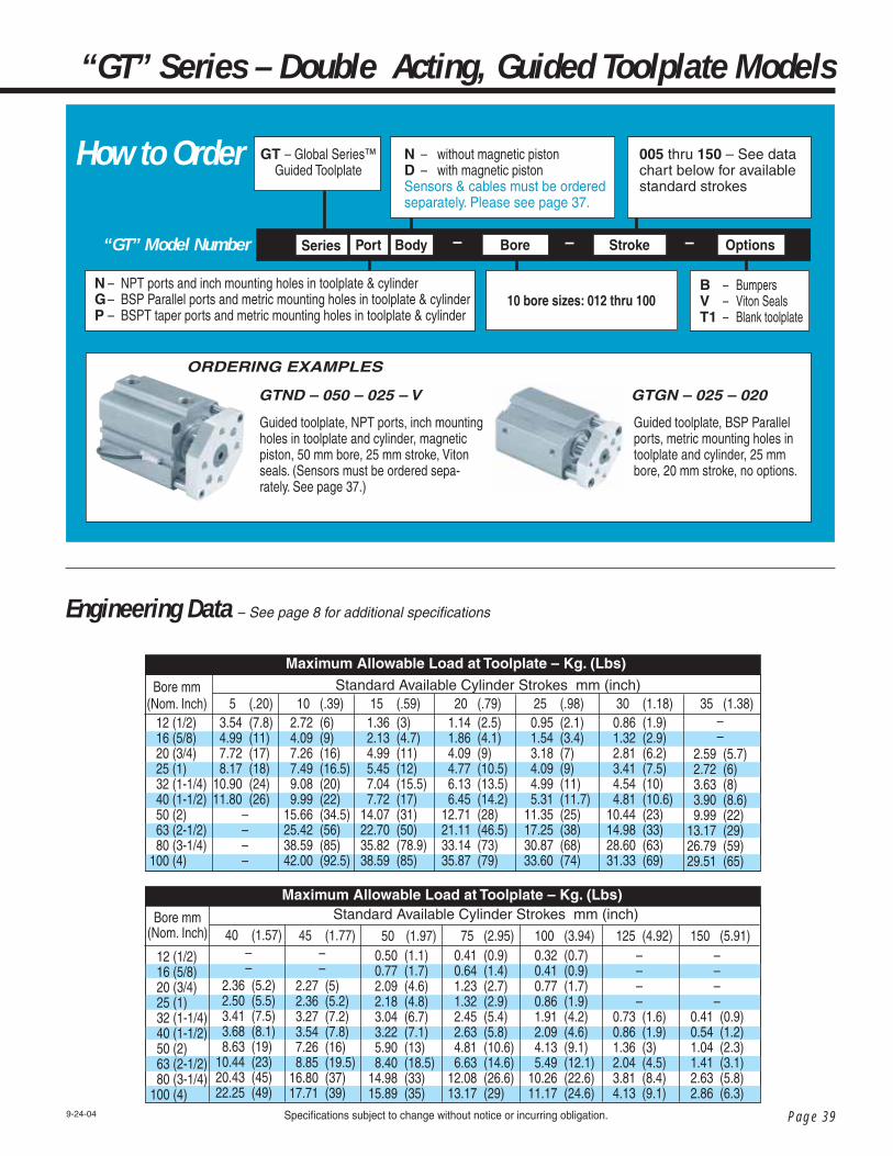
Page 39
Engineering Data – See page 8 for additional specifi cations
“GT” Model Number
N – NPT ports and inch mounting holes in toolplate & cylinderG – BSP Parallel ports and metric mounting holes in toolplate & cylinderP – BSPT taper ports and metric mounting holes in toolplate & cylinder
Bore Stroke OptionsBody – – –
N – without magnetic pistonD – with magnetic pistonSensors & cables must be ordered separately. Please see page 37.
GT – Global Series™ Guided Toolplate
B – Bumpers V – Viton Seals T1 – Blank toolplate
Series Port
How to Order
“GT” Series – Double Acting, Guided Toolplate Models
ORDERING EXAMPLES
9-24-04 Specifi cations subject to change without notice or incurring obligation.
10 bore sizes: 012 thru 100
005 thru 150 – See data chart below for available standard strokes
GTGN – 025 – 020
Guided toolplate, BSP Parallel ports, metric mounting holes in toolplate and cylinder, 25 mm bore, 20 mm stroke, no options.
GTND – 050 – 025 – V
Guided toolplate, NPT ports, inch mounting holes in toolplate and cylinder, magnetic piston, 50 mm bore, 25 mm stroke, Viton seals. (Sensors must be ordered sepa-rately. See page 37.)
Maximum Allowable Load at Toolplate – Kg. (Lbs)
50 (1.97) 0.50 (1.1) 0.77 (1.7) 2.09 (4.6) 2.18 (4.8) 3.04 (6.7) 3.22 (7.1) 5.90 (13) 8.40 (18.5) 14.98 (33) 15.89 (35)
75 (2.95) 0.41 (0.9) 0.64 (1.4) 1.23 (2.7) 1.32 (2.9) 2.45 (5.4) 2.63 (5.8) 4.81 (10.6) 6.63 (14.6) 12.08 (26.6) 13.17 (29)
100 (3.94) 0.32 (0.7) 0.41 (0.9) 0.77 (1.7) 0.86 (1.9) 1.91 (4.2) 2.09 (4.6) 4.13 (9.1) 5.49 (12.1) 10.26 (22.6) 11.17 (24.6)
125 (4.92)––––
0.73 (1.6) 0.86 (1.9) 1.36 (3) 2.04 (4.5) 3.81 (8.4) 4.13 (9.1)
150 (5.91)––––
0.41 (0.9) 0.54 (1.2) 1.04 (2.3) 1.41 (3.1) 2.63 (5.8) 2.86 (6.3)
Standard Available Cylinder Strokes mm (inch) 40 (1.57)
––
2.36 (5.2) 2.50 (5.5) 3.41 (7.5) 3.68 (8.1) 8.63 (19) 10.44 (23) 20.43 (45) 22.25 (49)
45 (1.77)––
2.27 (5) 2.36 (5.2) 3.27 (7.2) 3.54 (7.8) 7.26 (16) 8.85 (19.5) 16.80 (37) 17.71 (39)
Bore mm(Nom. Inch)
12 (1/2) 16 (5/8) 20 (3/4) 25 (1) 32 (1-1/4) 40 (1-1/2) 50 (2) 63 (2-1/2) 80 (3-1/4) 100 (4)
Maximum Allowable Load at Toolplate – Kg. (Lbs)
5 (.20) 3.54 (7.8) 4.99 (11) 7.72 (17) 8.17 (18) 10.90 (24)11.80 (26)
––––
10 (.39) 2.72 (6) 4.09 (9) 7.26 (16) 7.49 (16.5) 9.08 (20) 9.99 (22) 15.66 (34.5) 25.42 (56) 38.59 (85) 42.00 (92.5)
15 (.59) 1.36 (3) 2.13 (4.7) 4.99 (11) 5.45 (12) 7.04 (15.5) 7.72 (17) 14.07 (31) 22.70 (50) 35.82 (78.9) 38.59 (85)
20 (.79) 1.14 (2.5) 1.86 (4.1) 4.09 (9) 4.77 (10.5) 6.13 (13.5) 6.45 (14.2) 12.71 (28) 21.11 (46.5) 33.14 (73) 35.87 (79)
25 (.98) 0.95 (2.1) 1.54 (3.4) 3.18 (7) 4.09 (9) 4.99 (11) 5.31 (11.7) 11.35 (25) 17.25 (38) 30.87 (68) 33.60 (74)
30 (1.18) 0.86 (1.9) 1.32 (2.9) 2.81 (6.2) 3.41 (7.5) 4.54 (10) 4.81 (10.6) 10.44 (23) 14.98 (33) 28.60 (63) 31.33 (69)
35 (1.38)––
2.59 (5.7) 2.72 (6) 3.63 (8) 3.90 (8.6) 9.99 (22) 13.17 (29) 26.79 (59) 29.51 (65)
Standard Available Cylinder Strokes mm (inch)Bore mm(Nom. Inch) 12 (1/2) 16 (5/8) 20 (3/4) 25 (1) 32 (1-1/4) 40 (1-1/2) 50 (2) 63 (2-1/2) 80 (3-1/4) 100 (4)

Page 40
Global Series™Cylinders
Specifi cations subject to change without notice or incurring obligation. 5-12-06
Dimensional Data
Ø12 – Ø25 mm Bores
FF
CF
G
FF F C
'J' Tapped Thru4 Places
'S' Thru Hole 'U' Dia. C'Boreby 'Y' Deep 2 Places FromOther Side
Standard Toolplate will be provided when 'N' port code is specifi ed.
will be provided when 'G' or 'P' port code is specifi ed.
J6-326-328-328-32
C .94 1.10 1.38 1.54
Bore mm 12 16 20 25
F .63 .81 1.06 1.13
FF–
.44 .57 .66
G .82 .98 1.00 1.18
S–
.14 .17 .17
U––
.28–
Y––
.06–
Toolplate & Mounting – Inch DimensionsSpecifi ed by Port Code 'N'
RT .38 .51 .53 .59
OT8-328-32
1/4-201/4-20
C24283540
Bore mm 12 16 20 25
F 16.0 20.0 27.0 28.5
FF–
11.0 14.5 16.6
G 20.8 25.0 25.4 30.0
S–
3.3 4.2 4.2
U––––
Toolplate & Mounting – Metric Dimensions (mm)Specifi ed by Port Code 'G' or 'P'
RT 9.7 13.0 13.5 15.0
JM3 x 0.5M4 x 0.7M4 x 0.7M4 x 0.7
Y––––
OTM4 x 0.7M4 x 0.7M6 x 1.0M6 x 1.0
533.0 (1.30) 35.5 (1.40)36.5 (1.44)37.5 (1.48)
Boremm
12 16 20 25
10 38.0 (1.50) 40.5 (1.59) 41.5 (1.63) 42.5 (1.67)
15 43.0 (1.69) 45.5 (1.79) 46.5 (1.83) 47.5 (1.87)
20 48.0 (1.89) 50.5 (1.99) 51.5 (2.03) 52.5 (2.07)
25 53.0 (2.07) 55.5 (2.19) 56.5 (2.22) 57.5 (2.26)
30 58.0 (2.28) 60.5 (2.38) 61.5 (2.42) 62.5 (2.46)
35 –
– 66.5 (2.62) 67.5 (2.66)
40 –
– 71.5 (2.81) 72.5 (2.85)
45 –
– 76.5 (3.01) 77.5 (3.05)
'B ' Dimensions by Bore and Stroke for both Standard & Magnetic Piston shown as “mm (inches)”Stroke mm
Sensors for magnetic piston position indication must be ordered separately. See page 37.

Page 41
“GT” Series – Guided Toolplate Models – Dimensions
Specifi cations subject to change without notice or incurring obligation.5-12-06
L B
Q QE1
E1
*E2
P 2 Places
M
I Dia.
T
G
C'O' C'Bore'OT' Tapped Mounting Holex 'RT' Deep 2 Places
CØD
ØD2
RT
'OT' Threads This End Only
Duralon® Bearings
Cylinder Body Tapped Hole Mounting
will be provided when 'N' port code is specifi ed. will be provided when 'G' or 'P' port code is specifi ed.
* Port Size Offerings
Note:
M5 x 0.8 port will accept
#10-32 male thread fi ttings
Blank Toolplate Use Option Code T1 to specifya blank toolplate shown below.
* Note: See page 20 for additional cylinder body angle and profi le dimensions.
Boremm12162025
50 83.8 (3.30) 86.2 (3.39) 81.5 (3.21) 82.5 (3.25)
75 108.8 (4.28) 111.2 (4.38) 116.6 (4.59) 122.5 (4.82)
100 133.8 (5.27) 136.2 (5.36) 141.6 (5.57) 147.5 (5.81)
L3.5 (0.14)3.5 (0.14)4.5 (0.18)5 (0.20)
M22 (0.87)28 (1.10)36 (1.42)40 (1.57)
O – – 6.5 x 3.5 dp (0.26 x 0.14 dp) 9.0 x 7.0 dp (0.35 x 0.28 dp) 9.0 x 7.0 dp (0.35 x 0.28 dp)
*PM5x0.8M5x0.8M5x0.8M5x0.8
E223 (0.90) 27.2 (1.07) 31.2 (1.23) 36.9 (1.45)
E1 25 (0.98) 29 (1.14) 36 (1.42) 40 (1.57)
Boremm
12 16 20 25
I 31.5 (1.24) 37.1 (1.46) 47 (1.85) 51.3 (2.02)
T 6.1 (.24) 6.1 (.24) 6.9 (.27) 8.3 (.33)
Chart Dimensions shown as “mm (inches)”
ØD 6 (0.236) 8 (0.315) 10 (0.394) 12 (0.472)
ØD2 4.8 (0.188) 5 (0.197) 6 (0.236) 6 (0.236)
“Q” Port Location by Bore & StrokeStroke mmBore
mm12162025
50 8.9 (0.35) 10.2 (0.40) 8.1 (0.32) 8.4 (0.33)
75 8.9 (0.35) 10.2 (0.40) 12.1 (0.48) 12.7 (0.50)
100 8.9 (0.35) 10.2 (0.40) 12.1 (0.48) 12.7 (0.50)
5 – 45 7.0 (0.28) 7.8 (0.31) 8.1 (0.32) 8.4 (0.33)

Page 42
Global Series™Cylinders
Specifi cations subject to change without notice or incurring obligation. 10-28-04
Dimensional Data
C
E1
CE1
'J ' Tapped Thru 4 Places
FF
CF
FF
CF
'S' Thru Hole, 'U' Dia. C'Bore x 'Y' Deep 2 Places from Other Side
G G
Standard Toolplate Inch threads will be provided when 'N' port code is specifi ed.Metric threads will be provided when 'G' or 'P' port code is specifi ed.
Blank Toolplate Use Option Code T1 to specify
a blank toolplate shown below.
Ø32 – Ø100 mm Bores
J10-241/4-205/16-187/16-141/2-131/2-13
C 1.71 2.00 2.47 2.98 3.81 4.50
Bore mm3240506380100
F 1.19 1.38 1.75 2.00 2.75 3.25
FF .84 .97 1.24 1.41 1.95 2.30
G 1.44 1.78 2.25 2.69 3.50 4.45
S .20 .26 .33 .45 .52 .52
U––
.49 .68 .77 .77
Y––
.10 .18 .18 .13
Toolplate & Mounting – Inch DimensionsSpecifi ed by Port Code 'N'
RT .67 .75 .75 .87 1.13 1.13
OT1/4-201/4-205/16-187/16-141/2-131/2-13
C 43.4 50.5 62.7 75.7 96.9 114.4
Bore mm3240506380100
F 30.0 35.0 45.5 50.5 70.0 82.5
FF 21.2 24.7 32.2 35.7 49.5 58.3
S 5.2 6.1 8.2 11.5 12.3 12.3
U––
13.5 16.5 18.5 18.5
Toolplate & Mounting – Metric Dimensions (mm)Specifi ed by Port Code 'G' or 'P'
RT 17.0 19.0 19.0 22.0 29.0 29.0
JM5x 0.8M6x1.0
M8x1.25M10x1.5
M12x1.75M12x1.75
Y––
2.5 3.3 3.8 3.2
OTM6x1.0M6x1.0
M8x1.25M10x1.5
M12x1.75M12x1.75
G 36.7 45.1 57.1 68.3 88.9 112.9
528.0 (1.10)38.0 (1.50)34.5 (1.36)44.5 (1.75)
––––––––
Boremm
32 St'd Piston Mag. Piston 40 St'd Piston Mag. Piston 50 St'd Piston Mag. Piston 63 St'd Piston Mag. Piston 80 St'd Piston Mag. Piston 100 St'd Piston Mag. Piston
10 33.0 (1.30) 43.0 (1.69) 39.5 (1.56) 49.5 (1.95) 40.5 (1.59) 50.5 (1.99) 46.0 (1.81) 56.0 (2.20) 53.5 (2.11) 63.5 (2.50) 63.0 (2.48) 73.0 (2.87)
15 38.0 (1.50) 48.0 (1.89) 44.5 (1.75) 54.5 (2.15) 45.5 (1.79) 55.5 (2.19) 51.0 (2.01) 61.0 (2.40) 58.5 (2.30) 68.5 (2.70) 68.0 (2.68) 78.0 (3.07)
20 43.0 (1.69) 53.0 (2.09) 49.5 (1.95) 59.5 (2.34) 50.5 (1.99) 60.5 (2.38) 56.0 (2.20) 66.0 (2.60) 63.5 (2.50) 73.5 (2.89) 73.0 (2.87) 83.0 (3.27)
25 48.0 (1.89) 58.0 (2.28) 54.5 (2.15) 64.5 (2.54) 55.5 (2.19) 65.5 (2.58) 61.0 (2.40) 71.0 (2.80) 68.5 (2.70) 78.5 (3.09) 78.0 (3.07) 88.0 (3.46)
30 53.0 (2.09) 63.0 (2.48) 59.5 (2.34) 69.5 (2.74) 60.5 (2.38) 70.5 (2.78) 66.0 (2.60) 76.0 (2.99) 73.5 (2.89) 83.5 (3.29) 83.0 (3.27) 93.0 (3.66)
35 58.0 (2.28) 68.0 (2.68) 64.5 (2.54) 74.5 (2.93) 65.5 (2.58) 75.5 (2.97) 71.0 (2.80) 81.0 (3.19) 78.5 (3.09) 88.5 (3.48) 88.0 (3.46) 98.0 (3.86)
40 63.0 (2.48) 73.0 (2.87) 69.5 (2.74) 79.5 (3.13) 70.5 (2.78) 80.5 (3.17) 76.0 (2.99) 86.0 (3.39) 83.5 (3.29) 93.5 (3.68) 93.0 (3.66) 103.0 (4.06)
45 68.0 (2.68) 78.0 (3.07) 74.5 (2.93) 84.5 (3.33) 75.5 (2.97) 85.5 (3.37) 81.0 (3.19) 91.0 (3.58) 88.5 (3.48) 98.5 (3.88) 98.0 (3.86) 108.0 (4.25)
Stroke mm
'B ' Dimension by Bore & Stroke shown as “mm (inches)”

Page 43Specifi cations subject to change without notice or incurring obligation.5-17-06
“GT” Series – Guided Toolplate Models – Dimensions
Q
Q
L B
P 2 Places
ZM
MW
Ø32 – Ø100mm Bores'N' Thru Hole & 'O' C'Bore for SHCS2 Places From Each End'OT' Tapped Mounting Hole x 'RT' Deep2 Places From Each End
I Dia.
T
ØD
ØD2
Slots (2) for round profile sensors.See page 37.
RT RT
'OT' Threads Both Ends
Cylinder Body Tapped Hole Mounting
will be provided when 'N' port code is specifi ed. will be provided when 'G' or 'P' port code is specifi ed.
N– NPT ports, inch toolplate & mounting threadsG– BSP parallel ports, metric toolplate & mounting threadsP– BSPT taper ports, metric toolplate & mounting threads
* Port Size Offerings - See dimension column “P” below
‡ Note: On 32 bore, 5mm stroke, non-magnetic model only, port thread is M5x0.8 which will accept #10-32 male thread fi ttings.
50 73.0 (2.87) 83.0 (3.27) 79.5 (3.13) 89.5 (3.52) 80.5 (3.17) 90.5 (3.56) 86.0 (3.39) 96.0 (3.78) 93.5 (3.68) 103.5 (4.07) 103.0 (4.06) 113.0 (4.45)
75 108.0 (4.25) 108.0 (4.25) 114.5 (4.51) 114.5 (4.51) 115.5 (4.55) 115.5 (4.55) 121.0 (4.76) 121.0 (4.76) 128.5 (5.06) 128.5 (5.06) 138.0 (5.43) 138.0 (5.43)
100 133.0 (5.24) 133.0 (5.24) 139.5 (5.49) 139.5 (5.49) 140.5 (5.53) 140.5 (5.53) 146.0 (5.75) 146.0 (5.75) 153.5 (6.04) 153.5 (6.04) 163.0 (6.42) 163.0 (6.42)
125 172.8 (6.80) 172.8 (6.80) 180.5 (7.11) 180.5 (7.11) 184.3 (7.26) 184.3 (7.26) 189.6 (7.46) 189.6 (7.46) 194.5 (7.66) 194.5 (7.66) 201.7 (7.94) 201.7 (7.94)
150 197.8 (7.79) 197.8 (7.79) 205.5 (8.09) 205.5 (8.09) 209.3 (8.24) 209.3 (8.24) 214.6 (8.49) 214.6 (8.49) 219.5 (8.64) 219.5 (8.64) 226.7 (8.93) 226.7 (8.93)
Stroke mm'B ' Dimension by Bore & Stroke shown as“mm (inches)”
Boremm
32 St'd Piston Mag. Piston 40 St'd Piston Mag. Piston 50 St'd Piston Mag. Piston 63 St'd Piston Mag. Piston 80 St'd Piston Mag. Piston 100 St'd Piston Mag. Piston
Bore mm3240506380100
L 7 (0.28) 7 (0.28) 8 (0.31) 8 (0.31) 10 (0.39) 12 (0.47)
M 34 (1.34) 40 (1.57) 50 (1.97) 60 (2.36) 77 (3.03) 94 (3.70)
O 9.0 x 7.0 dp (0.35 x 0.28 dp) 9.0 x 7.0 dp (0.35 x 0.28 dp) 11.0 x 8.0 dp (0.43 x 0.31 dp) 13.7 x 10.5 dp (0.54 x 0.41 dp) 16.8 x 13.5 dp (0.66 x 0.53 dp) 16.8 x 13.5 dp (0.66 x 0.53 dp)
*P1/8*‡1/8*1/4*1/4*3/8*3/8*
E1 44.5 (1.75) 52 (2.05) 63.7 (2.51) 76.7 (3.02) 97.8 (3.85) 115.3 (4.54)
I 58.9 (2.32) 69 (2.72) 84.9 (3.34) 101.8 (4.01) 129.8 (5.11) 153.9 (6.06)
W 49.3 (1.94) 57.0 (2.24) 70.6 (2.78) 83.6 (3.29) 104 (4.09) 121.9 (4.80)
Z 16.5 (0.65)17.8 (0.70)22.2 (0.88)22.2 (0.88)27.0 (1.06)27.0 (1.06)
N5.5 (0.22)5.5 (0.22)6.6 (0.26)9 (0.35)11 (0.43)11 (0.43)
T 8.3 (0.33) 8.3 (0.33) 12.1 (0.48) 12.5 (0.49) 14.0 (0.55) 14.0 (0.55)
Chart Dimensions shown as“mm (inches)”
ØD 16 (0.630) 16 (0.630) 20 (0.787) 20 (0.787) 25 (0.984) 30 (1.181)
ØD2 7 (0.276) 7 (0.276) 8 (0.315) 11.1 (0.438) 16 (0.630) 16 (0.630)
5 – 100 8.7 (0.34) 9.2 (0.36) 10.5 (0.41) 11.5 (0.45) 14.0 (0.55) 18.0 (0.71)
“Q” Port Location by Bore & Stroke
Bore mm3240506380100
Stroke mm125, 150
12.7 (0.50) 12.7 (0.50) 13.2 (0.52) 18.5 (0.73) 14.0 (0.55) 18.0 (0.71)

Page 44
How to OrderG– Global Series™
N– NPT ports, inch rod threadG– BSP Parallel ports, metric rod threadP– BSPT taper ports, metric rod thread
Model Mounting Bore Stroke Action OptionsSeries Port Body –
mm 5 10 15 20 25 30 50 75 100 5 10 15 20 25 30 50 75 100 5 10 15 20 25 30 35 40 45 50 75 100 5 10 15 20 25 30 35 40 45 50 75 100 5 10 15 20 25 30 35 40 45 50 75 100 125 150
Bore
mm
12
16
20
25
32
Stro
ke
D 26.80 27.90 28.95 29.95 31.00 33.15 39.05 42.05 45.55 30.50 31.55 32.60 33.65 34.65 36.80 40.25 43.20 46.75 36.65 37.70 38.70 39.80 40.85 41.80 42.85 42.90 43.90 45.70 56.30 60.50 41.65 42.80 44.00 45.10 46.30 47.45 48.65 49.75 50.95 52.75 63.25 72.35 46.50 47.65 48.90 50.05 51.20 52.35 53.55 54.70 55.85 57.00 62.85 68.70 81.55 93.70
Model CodeAction Code(Base Price)
– –
MagnetPistonCode D
012••••••
100
005••••••
150
D– double actingS– single acting, spring retract – 012 thru 050 bore only T– single acting, spring extend – 012 thru 050 bore only
4.80
6.00
7.80
7.80
14.50
N– without magnetic piston (std) D– with magnetic piston (adder)
See sensors, cables and accessory prices on page 47
W
8.95
11.60
14.30
18.65
20.35 20.35 20.35 20.35 20.35 20.35 22.45 22.45 22.45 22.45 22.45 22.45 22.45 22.45
V
3.35
4.10
4.45
5.20
6.30
P
3.75
3.75
4.25
4.25
4.25
RS
N/A
N/A
15.25
15.70
26.25
E or F
N/C
N/C
N/C
N/C
N/C
B
5.25
6.00
6.00
6.00
7.20
M or N
1.85
1.85
2.10
2.10
2.10
25.90
25.90
37.95
37.95
39.70
XC10
23.50
26.20
26.55
29.80
31.30
S– single rod (standard)W– double rodT– double rod hole thruK– non-rotating single rodL– non-rotating double rodM– non-rotating double rod hole thruA– adjustable stroke extend (includes Mounting Code A – tapped holes)
Add on Prices
XC11XC12
B– bumpers, both ends M– male rod, rod end N– male rod, cap end P– male rod, both ends E– boss, rod end F– boss, cap end RS– adjustable stroke, retract V– high temperature seals
B– thru hole (standard)L– foot mountE– fl ange rod endF– fl ange cap endG– ISO fl ange rod endH– ISO fl ange cap endC– rear clevisA– tapped both endsSee prices on page 47
S 22.30 22.60 – – – – – – – 27.25 28.10 – – – – – – – 32.75 33.70 – – – – – – – – – – 33.15 34.45 – – – – – – – – – – 35.90 39.85 – – – – – – – – – – – –
T 25.15 25.55 – – – – – – – 28.75 30.65 – – – – – – – 34.60 35.55 – – – – – – – – – – 27.95 35.40 – – – – – – – – – – 37.20 41.15 – – – – – – – – – – – –
K
39.30
45.70
45.70
45.70
45.70
A
N/A
N/A
N/A
N/A
– – 57.90 – 57.90 – – – – 69.50 83.30 94.95 107.05 118.20
L
48.95
58.10
60.95
65.60
67.55 67.55 67.55 67.55 67.55 67.55 69.65 69.65 69.65 69.65 69.65 69.65 69.65 69.65
M
N/A
67.90
70.80
75.50
77.35 77.35 77.35 77.35 77.35 77.35 79.55 79.55 79.55 79.55 79.55 79.55 79.55 79.55
Option Code
T
N/A
20.85
23.45
27.90
29.60 29.60 29.60 29.60 29.60 29.60 31.65 31.65 31.65 31.65 31.65 31.65 31.65 31.65
9-9-10
Global Series™ List Prices
Effective October 1, 2010

Page 45
Bore
Stro
ke
Model CodeAdd on PricesAction Code
(Base Price)mm
5 10 15 20 25 30 35 40 45 50 75 100 125 150 10 15 20 25 30 35 40 45 50 75 100 125 150 10 15 20 25 30 35 40 45 50 75 100 125 150 10 15 20 25 30 35 40 45 50 75 100 125 150 10 15 20 25 30 35 40 45 50 75 100 125 150
mm
40
50
63
80
100
T 44.25 45.15 – – – – – – – – – – – – 63.25 – 65.85
–––––––––––––––––––––––––––––––––––––––––––––––––
D 55.25 56.45 57.70 58.85 60.10 61.30 62.60 63.85 65.00 66.25 72.35 78.55 89.65 102.40 68.20 69.85 71.45 73.05 74.60 76.25 77.80 79.40 81.00 88.95 96.90 106.15 120.00 80.75 82.50 84.15 85.90 87.55 89.30 91.00 92.75 94.50 103.00 111.65 146.65 157.55 100.90 102.80 104.80 106.80 108.70 110.65 112.55 114.60 116.55 126.30 136.20 149.55 164.50 150.90 153.35 155.80 158.25 160.70 163.10 165.60 168.15 170.55 182.80 195.05 208.60 224.50
Model Mounting Bore Stroke Action OptionsSeries Port Body – – –
012••••••
100
005••••••
150
G–Global Series™
N–NPT ports, inch rod threadG–BSP Parallel ports, metric rod threadP–BSPT taper ports, metric rod thread
D– double actingS– single acting, spring retract – 012 thru 050 bore onlyT– single acting, spring extend – 012 thru 050 bore only
How to Order
MagnetPistonCode D
S– single rod (standard)W– double rodT– double rod hole thruK– non-rotating single rodL– non-rotating double rodM– non-rotating double rod hole thruA– adjustable stroke extend (includes Mounting Code A – tapped holes)
B– thru hole (standard)L– foot mountE– fl ange rod endF– fl ange cap endG– ISO fl ange rod endH– ISO fl ange cap endC– rear clevisA– tapped both endsSee prices on page 47
B– bumpers, both ends M– male rod, rod end N– male rod, cap end P– male rod, both ends E– boss, rod end F– boss, cap end RS– adjustable stroke, retract V– high temperature seals XC10– back-to-back XC11, XC12– tandem
N– without magnetic piston (std) D– with magnetic piston (adder)
See sensors, cables and accessory prices on page 47
XC11XC12W
21.20 21.20 21.20 21.20 21.20 21.20 24.30 24.30 24.30 24.30 24.30 24.30 24.30 24.30 38.65 38.65 38.65 38.65 38.65 47.25 47.25 47.25 47.25 47.25 47.25 47.25 47.25 44.80 44.80 44.80 44.80 44.80 51.80 51.80 51.80 51.80 51.80 51.80 51.80 51.80 44.80 44.80 44.80 44.80 44.80 51.80 51.80 51.80 51.80 51.80 51.80 51.80 51.80 47.55 47.55 47.55 47.55 47.55 52.95 52.95 52.95 52.95 52.95 52.95 52.95 52.95
T 32.25 32.25 32.25 32.25 32.25 32.25 35.35 35.35 35.35 35.35 35.35 35.35 35.35 35.35 49.65 49.65 49.65 49.65 49.65 58.30 58.30 58.30 58.30 58.30 58.30 58.30 58.30 55.80 55.80 55.80 55.80 55.80 62.80 62.80 62.80 62.80 62.80 62.80 62.80 62.80
55.80 55.80 55.80 55.80 55.80 62.80 62.80 62.80 62.80 62.80 62.80 62.80 62.80
61.00 61.00 61.00 61.00 61.00 66.40 66.40 66.40 66.40 66.40 66.40 66.40 66.40
Option Code
14.50
19.25
19.25
23.50
34.95
L 63.35 63.35 63.35 63.35 63.35 63.35 66.65 66.65 66.65 66.65 66.65 66.65 66.65 66.65 81.95 81.95 81.95 81.95 81.95 91.15 91.15 91.15 91.15 91.15 91.15 91.15 91.15 89.20 89.20 89.20 89.20 89.20 96.10 96.10 96.10 96.10 96.10 96.10 96.10 96.10 99.55 99.55 99.55 99.55 99.55 113.15 113.15 113.15 113.15 113.15 113.15 113.15 113.15 140.15 140.15 140.15 140.15 140.15 156.35 156.35 156.35 156.35 156.35 156.35 156.35 156.35
M 75.20 75.20 75.20 75.20 75.20 75.20 78.45 78.45 78.45 78.45 78.45 78.45 78.45 78.45 93.75 93.75 93.75 93.75 93.75 103.05 103.05 103.05 103.05 103.05 103.05 103.05 103.05 100.35 100.35 100.35 100.35 100.35 107.85 107.85 107.85 107.85 107.85 107.85 107.85 107.85 113.90 113.90 113.90 113.90 113.90 127.60 127.60 127.60 127.60 127.60 127.60 127.60 127.60 152.00 152.00 152.00 152.00 152.00 162.90 162.90 162.90 162.90 162.90 162.90 162.90 162.90
A – – 57.90 – 57.90 – – – – 69.50 83.30 94.95 107.05 118.20 – 86.85 – 86.85 – – – – 104.45 121.95 139.35 156.95 174.40 – 86.85 – 86.85 – – – – 104.45 121.95 139.35 156.95 174.40 – 86.85 – 86.85 – – – – 104.45 121.95 139.35 156.95 174.40 – 86.85 – 86.85 – – – – 104.45 121.95 139.35 156.95 174.40
B
8.50
8.50
10.25
15.70
18.05
40.95
51.75
73.40
75.25
84.25
V
8.50
10.50
12.05
14.25
30.30
P
4.85
12.25
12.25
16.10
18.95
RS
26.25
26.25
26.25
27.40
35.10
E or F
N/C
N/C
N/C
N/C
N/C
XC10
34.40
47.55
50.60
61.40
68.65
M or N
2.45
6.10
6.10
8.10
9.40
K
45.70
45.70
45.70
56.45
68.30
S 42.70 43.65 – – – – – – – – – – – – 60.05 – 63.25 – – – – – – – – – – – – – – – – – – – – – – – – – – – – – – – – – – – – – – – – – – – – – – – – –
9-9-10

Page 46
“GT”
Model
Number
N– NPT ports, inch threads toolplate & mountingG– BSP Parallel ports, metric threads toolplate & mountingP– BSPT taper ports, metric threads toolplate & mounting
Bore Stroke OptionsBody – – –
N– without magnetic piston (std) D– with magnetic piston (adder)
See sensors, cables and accessory prices on page 47
Option Codes
mm 5 10 15 20 25 30 35 40 45 50 75 100 125 150 5 10 15 20 25 30 35 40 45 50 75 100 125 150 10 15 20 25 30 35 40 45 50 75 100 125 150
Bore
mm
32
40
50
Stro
ke
95.10 96.35 97.60 98.80 100.10 101.35 102.55 103.80 105.05 106.35 120.00 126.20 139.95152.95 104.45 105.65 107.00 108.30 109.70 110.95 112.25 113.55 114.85 116.15 130.15 136.70 148.70 162.20 118.30 120.00 121.65 123.40 125.10 126.80 128.50 130.20 131.95 147.85 156.40 166.35 181.05
Add on Prices
Base
Pric
e
Bum
pers
Mag
netic
Pist
on
Vito
n Sea
ls
V
7.05
9.60
11.80
T
N/C
N/C
N/C
Option Codes
mm 5 10 15 20 25 30 50 75 100 5 10 15 20 25 30 50 75 100 5 10 15 20 25 30 35 40 45 50 75 100 5 10 15 20 25 30 35 40 45 50 75 100
Bore
mm
12
16
20
25
Stro
ke
64.95 66.00 67.15 68.30 69.40 71.75 78.10 84.75 88.45 68.85 69.90 71.05 72.15 73.30 75.60 79.35 85.85 89.75 78.45 79.55 80.70 81.80 83.00 84.05 85.10 85.25 86.20 88.10 104.90 109.60 85.85 87.20 88.45 89.65 90.90 92.15 93.40 94.65 95.85 97.85 113.05 122.75
Add on Prices
Base
Pric
e
Bum
pers
Mag
netic
Pist
on
Vito
n Sea
ls
Option Codes
mm 10 15 20 25 30 35 40 45 50 75 100 125 150 10 15 20 25 30 35 40 45 50 75 100 125 150 10 15 20 25 30 35 40 45 50 75 100 125 150
Bore
mm
63
80
100
Stro
ke
146.20 148.05 149.90 151.75 153.65 155.40 157.30 160.00 160.95 185.55 194.75 232.15 243.85 179.95 182.00 184.10 186.25 188.30 190.45 192.50 194.65 196.70 229.50 240.05 254.35 270.40 243.30 245.95 248.50 251.25 253.85 256.45 259.10 261.65 264.30300.70 313.90 328.30 345.35
Add on Prices
Base
Pric
e
Bum
pers
Mag
netic
Pist
on
Vito
n Sea
ls
V
13.55
16.00
34.05
B
11.50
17.65
20.30
GT– Global Series™ Guided Toolplate
B– Bumpers V– Viton Seals T1– Blank toolplate
Series Port
Blan
k To
olplat
e
Blan
k To
olplat
e
D
21.60
26.45
39.25
D
5.40
6.75
8.75
8.75
B
5.90
6.75
6.75
6.75
V
3.75
4.60
5.00
5.85
T
N/C
N/C
N/C
N/C
Blan
k To
olplat
e
T
N/C
N/C
N/C
B
8.10
9.60
9.60
D
16.30
16.30
21.60
9-9-10
Global Series™ List PricesEffective October 1, 2010

Page 47
Price
$19.30
27.30
27.30
Magnetic Sensors – Electrical Characteristics Part Numbers and Prices Sensor Type
Reed Switch forPLC’s w/LED
(current limiting)ElectronicLED andSourcingElectronicLED andSInking
SPST Normally Open
PNP Normally Open
NPN Normally Open Normally Open
SwitchingSpeed
0.5 ms operate0.1 ms release
1.5µs operate0.5µs release
1.5µs operate0.5µs release
SwitchingPower
4 Watts max.
6 Watts max.
6 Watts max.
Prewired 9 ft.Part No.
9C49-000-002
9C49-000-031
9C49-000-032
Quick Disconnect
9C49-000-302 Requires 3 pin
cordset9C49-000-331Requires 3 pin
cordset9C49-000-332Requires 3 pin
cordset
Price
$25.70
31.65
31.65
SwitchingVoltage
5-120V AC/DC50/60 Hz
6-30 VDC
6-30 VDC
SwitchingCurrent
0.04 Amp max0.005 Amp min.
0.2 Amp max.
0.2 Amp max.
VoltageDrop
2.5 Volts
1.5 Volts
1.5 Volts
Function
Dovetail Magnetic Sensors
Round Profi le Magnetic Sensors
These fi t into the 4mm keyhole slots adjacent to the cylinder ports of the new extrusion shown on pages 21, 23, 25, 27 29, 42 & 43.
MountingCode Adders andAccessory Prices
The sensors feature surge suppression, polarity protection, LED indicator and extremely fast switching speeds.
Mounting Code Price AddersB
Std.Std.Std.Std.Std.Std.Std.Std.Std.Std.
C $9.75 9.75 10.85 10.85 12.35 14.75 17.75 23.35 31.45 43.40
A $1.75 1.75 1.75 1.75 3.50 3.50 3.50 3.50 3.50 3.50
Bore mm121620253240506380100
L, E, F, G or H $7.60 9.10 9.35 9.90 11.05 13.95 16.70 20.00 23.55 26.55
Rod Clevis $7.40 7.90 8.30 11.15 13.55 15.80 17.05 17.05 22.70 27.95
Accessory PricesPart No. [ Use “RE” or “RC in box ( ) ] ■ ■ –8–32–12 or ■ ■ –M5 x 0.8 ■ ■ –8-32–16 or ■ ■ –M6 x 1 ■ ■ –10–32 or ■ ■ –M8 x 1.25 ■ ■ –1/4–28 or ■ ■ –M10 x 1.25 ■ ■ –5/16-24 or ■ ■ –M14 x 1.5 ■ ■ –3/8–24 or ■ ■ –M14 x 1.5 ■ ■ –1/2–20 or ■ ■ –M18 x 1.5 ■ ■ –1/2–20 or ■ ■ –M18 x 1.5 ■ ■ –5/8–18 or ■ ■ –M22 x 1.5 ■ ■ –3/4–16 or ■ ■ –M26 x 1.5
Rod Eye $5.55 6.30 6.75 8.60 13.55 14.10 15.80 15.80 20.35 24.00
Bore mm121620253240506380100
8mmFemaleCordsets
3/8”
Dov
etai
l1/
4” D
ovet
ail
Sensor Type WireLeads
2233
2233
0-120 VDC/VAC, 0.5 Amp Max, 5 Watt Max, 0 Voltage Drop5-120 VDC/VAC, 0.03 Amp Max, 4 Watt Max, 2.0 Voltage DropSourcing PNP 6-24 VDC, 0.20 Amp Max, 0.5 Voltage DropSinking NPN 6-24 VDC, 0.20 Amp Max, 0.5 Voltage Drop
0-120 VDC/VAC, 0.5 Amp Max, 5 Watt Max, 0 Voltage Drop5-120 VDC/VAC, 0.03 Amp Max, 4 Watt Max, 2.0 Voltage DropSourcing PNP 6-24 VDC, 0.20 Amp Max, 0.5 Voltage DropSinking NPN 6-24 VDC, 0.20 Amp Max, 0.5 Voltage Drop
Reed (No LED) Reed (LED)
Electronic (LED)Electronic (LED)
Reed (No LED) Reed (LED)
Electronic (LED)Electronic (LED)
Prewired 9 ft.Part No. Price949-000-001 .... $18.05949-000-002 ...... 18.85949-000-031 ...... 23.80949-000-032 ...... 23.80
949-200-001 .... $20.15949-200-002 ...... 20.90949-200-031 ...... 25.95949-200-032 ...... 25.95
Quick DisconnectPart No. Price949-000-301 .... $25.65949-000-302 ...... 26.30949-000-331 ...... 31.30949-000-332 ...... 31.30
949-200-301 .... $27.70949-200-302 ...... 28.95949-200-331 ...... 33.45949-200-332 ...... 33.45
Electrical Characteristics
Cordset Description
1 meter length, 3 Pin
2 meters length, 3 Pin
5 meters length, 3 Pin
Part No.
CFC-1M
CFC-2M
CFC-5M
List Prices
$14.35
16.05
20.30
Seal Kits Bore Seal Kit Price Non-rotating Seal Price 40 G40-SK $5.70 G32-DDS16V $13.90 G40-SKV 9.20 50 G50-SK 7.10 G50-DDS20V 14.40 G50-SKV 12.70 63 G63-SK 7.60 G50-DDS20V 14.40 G63-SKV 13.50 80 G80-SK 10.15 G80-DDS25V 15.60 G80-SKV 20.40 100 G100-SK 12.95 G100-DDS30 15.95 G100-SKV 29.70
Bore Seal Kit Price Non-rotating Seal Price 12 G12-SK $4.05 G12-DDS6V $9.80 G12-SKV 3.60 16 G16-SK 4.15 G16-DDS8V 10.40 G16-SKV 4.45 20 G20-SK 4.25 G20-DDS10V 10.70 G20-SKV 4.55 25 G25-SK 4.40 G25-DDS12V 11.05 G25-SKV 4.80 32 G32-SK 4.85 G32-DDS16V 13.90 G32-SKV 5.70
12-17-09
Mounting Codes, Accessories, & Sensors

12-09
FABCO-AIR, Inc. ■ 3716 N.E. 49th Avenue ■ Gainesville, FL 32609-1699 ■ Telephone (352) 373-3578 ■ Fax (352) 375-8024 ■ E-Mail [email protected]
■ Web Site http://www.fabco-air.com
Fabco-Air Product Catalog Library
Linear Slides - 6 FamiliesCatalog # LS-03
ISO 6431 Cylinders Catalog # FAQR-09
Manifold Solenoid Valves Catalog # FVS.Y-09
Swing Clamps, Pneumatic & HydraulicCatalog # FML.H
Air Pilot & Solenoid Valves Catalog # FVA.E-09
Twin Rod, Non-Rotating Air Cylinders - Catalog # FDF-09 and Catalog # FDXS-09
Multi-Power® Air PressesCatalog # FP16
Pancake® II Air CylindersCatalog Pan2-2
S Pneumatic Grippers, Parallel Jaw and Angular Motion - Catalog # GR-8
Stopper CylindersCatalog # ST-SC
Swing ClampsBulletin # SC-DB04
Square Pancake® II Air CylindersCatalog # SqPan2
Cylinders, Valves and Accessories Catalog #CV9
NFPA Interchangeable Air Cylinders - Catalog # NF-6
Stainless Steel BodyAir CylindersCatalog SSB-03
Modular Air Preparation System - FRLsCatalog # FRL-06
ModM d lula Ar Aiir PPrepar tiation
ISO 6431 Cylinders
Swing Clamps
Twii Rn R dod NNo Rn Rota itin Ag Aiir
ISO 6432 Cylinders Catalog # FAE-09
Ai Pil t & S l id V l
PneumaticAngular GrippersCatalog # FKA-09
Guided Motion Air CylindersCatalog # FGM-10
Air Slide TablesCatalog # FGXS-10