Embed Size (px)
Citation preview
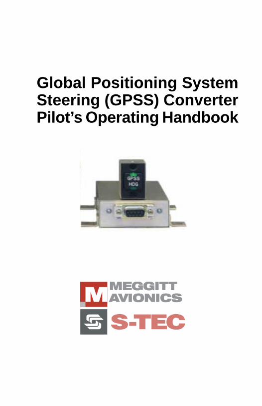
Global Positioning SystemSteering (GPSS) ConverterPilot’s Operating Handbook
4th Ed: September 05, 2003 i
GPSS POH
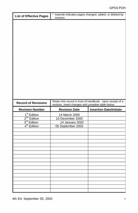
List of Effective Pages * Asterisk indicates pages changed, added, or deleted byrevision.
Record of Revisions Retain this record in front of handbook. Upon receipt of arevision, insert changes and complete table below.
Revision Number Revision Date Insertion Date/Initials
1st Edition 14 March 20002nd Edition 13 December 2000
3rd Edition 14 January 20024th Edition 05 September 2003

ii 4th Ed: September 05, 2003
GPSS POH
Page Intentionally Blank
4th Ed: September 05, 2003 iii
GPSS POH
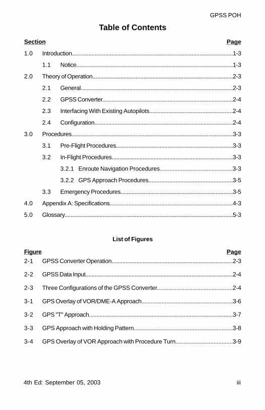
Table of Contents
Section Page
1.0 Introduction..........................................................................................................1-3
1.1 Notice........................................................................................................1-3
2.0 Theory of Operation...........................................................................................2-3
2.1 General....................................................................................................2-3
2.2 GPSS Converter......................................................................................2-4
2.3 Interfacing With Existing Autopilots....................................................2-4
2.4 Configuration..........................................................................................2-4
3.0 Procedures..........................................................................................................3-3
3.1 Pre-Flight Procedures...........................................................................3-3
3.2 In-Flight Procedures..............................................................................3-3
3.2.1 Enroute Navigation Procedures.............................................3-3
3.2.2 GPS Approach Procedures.....................................................3-5
3.3 Emergency Procedures........................................................................3-5
4.0 Appendix A: Specifications...............................................................................4-3
5.0 Glossary..............................................................................................................5-3
List of Figures
Figure Page
2-1 GPSS Converter Operation..............................................................................2-3
2-2 GPSS Data Input................................................................................................2-4
2-3 Three Configurations of the GPSS Converter...............................................2-4
3-1 GPS Overlay of VOR/DME-A Approach...........................................................3-6
3-2 GPS "T" Approach..............................................................................................3-7
3-3 GPS Approach with Holding Pattern..............................................................3-8
3-4 GPS Overlay of VOR Approach with Procedure Turn....................................3-9

iv 4th Ed: September 05, 2003
GPSS POH
Page Intentionally Blank

4th Ed: September 05, 2003 1-1
GPSS POH
SECTION 1INTRODUCTION

1-2 4th Ed: September 05, 2003
GPSS POH
Page Intentionally Blank
4th Ed: September 05, 2003 1-3
GPSS POH
1.0 Introduction
The primary purpose of the GPS Steering (GPSS) Converter Pilot OperatingHandbook (POH) is to provide pilots with step-by-step functional Preflightand In-Flight Operating Procedures for the installed system.
1.1 Notice
This manual may be used in conjunction with FAA approved autopilot AirplaneFlight Manual Supplement (AFMS), Pilots Operating Handbook Supplement(POHS), or Supplemental Flight Manual (SFM). Refer to the specific AFMS,POHS or SFM for your aircraft specific information and emergency operatingprocedures.
If the autopilot is to be used during Instrument Flight Rules (IFR) operations,we recommend that you develop a thorough understanding of the autopilotsystem, its functions and characteristics in Visual Meteorological Conditions(VMC). Accomplish this before undertaking a IFR flight.

1-4 4th Ed: September 05, 2003
GPSS POH
Page Intentionally Blank
4th Ed: September 05, 2003 2-1
GPSS POH
SECTION 2THEORY OF OPERATION

2-2 4th Ed: September 05, 2003
GPSS POH
Page Intentionally Blank
4th Ed: September 05, 2003 2-3
GPSS POH
2.0 Theory of Operation
2.1 General
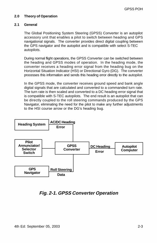
The Global Positioning System Steering (GPSS) Converter is an autopilotaccessory unit that enables a pilot to switch between heading and GPSnavigational signals. The converter provides direct digital coupling betweenthe GPS navigator and the autopilot and is compatible with select S-TECautopilots.
During normal flight operations, the GPSS Converter can be switched betweenthe heading and GPSS modes of operation. In the heading mode, theconverter receives a heading error signal from the heading bug on theHorizontal Situation Indicator (HSI) or Directional Gyro (DG). The converterprocesses this information and sends this heading error directly to the autopilot.
In the GPSS mode, the converter receives ground speed and bank angledigital signals that are calculated and converted to a commanded turn rate.The turn rate is then scaled and converted to a DC heading error signal thatis compatible with S-TEC autopilots. The end result is an autopilot that canbe directly coupled to the roll steering commands produced by the GPSNavigator, eliminating the need for the pilot to make any further adjustmentsto the HSI course arrow or the DG’s heading bug.
Fig. 2-1. GPSS Converter Operation
PilotAnnunciator/
SelectorSwitch
Heading System
GPSNavigator
Roll SteeringData
GPSSConverter
AC/DC Heading
DC HeadingError
AutopilotComputer
Error
2-4 4th Ed: September 05, 2003
GPSS POH
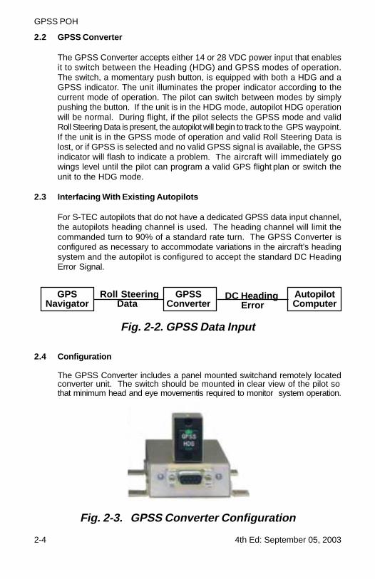
Fig. 2-2. GPSS Data Input
Fig. 2-3. GPSS Converter Configuration
2.2 GPSS Converter
The GPSS Converter accepts either 14 or 28 VDC power input that enablesit to switch between the Heading (HDG) and GPSS modes of operation.The switch, a momentary push button, is equipped with both a HDG and aGPSS indicator. The unit illuminates the proper indicator according to thecurrent mode of operation. The pilot can switch between modes by simplypushing the button. If the unit is in the HDG mode, autopilot HDG operationwill be normal. During flight, if the pilot selects the GPSS mode and validRoll Steering Data is present, the autopilot will begin to track to the GPS waypoint.If the unit is in the GPSS mode of operation and valid Roll Steering Data islost, or if GPSS is selected and no valid GPSS signal is available, the GPSSindicator will flash to indicate a problem. The aircraft will immediately gowings level until the pilot can program a valid GPS flight plan or switch theunit to the HDG mode.
2.3 Interfacing With Existing Autopilots
For S-TEC autopilots that do not have a dedicated GPSS data input channel,the autopilots heading channel is used. The heading channel will limit thecommanded turn to 90% of a standard rate turn. The GPSS Converter isconfigured as necessary to accommodate variations in the aircraft’s headingsystem and the autopilot is configured to accept the standard DC HeadingError Signal.
2.4 Configuration
The GPSS Converter includes a panel mounted switchand remotely locatedconverter unit. The switch should be mounted in clear view of the pilot sothat minimum head and eye movementis required to monitor system operation.
GPSNavigator
Roll Steering Data
GPSSConverter
DC Heading Error
AutopilotComputer
4th Ed: September 05, 2003 3-1
GPSS POH
SECTION 3PROCEDURES

3-2 4th Ed: September 05, 2003
GPSS POH
Page Intentionally Blank
4th Ed: September 05, 2003 3-3
GPSS POH
3.0 Procedures
3.1 Pre-Flight Procedures
NOTE: The GPSS Converter requires either 14 or 28 VDCas input power.
1. Place aircraft master and avionics switches to on.
NOTE: When aircraft power is applied, the HDG lamp onthe GPSS panel switch will illuminate. This indicatesthat the autopilot, when turned on, will operatenormally in heading mode, when selected.
2. Place the autopilot master switch to ON.
3. Select the HDG mode on the autopilot after the ready (RDY) annunciatorappears.
4. Move the DG or HSI heading bug left and right. The control wheelshould smoothly follow the HDG bug movement.
5. Activate a valid GPS waypoint or flight plan on the GPS Navigator.
6. Press and release the GPSS switch, the HDG lamp goes out and theGPSS lamp flashes. The HDG bug will no longer move the control wheel.
NOTE: The GPSS steering function cannot be ground testedeven though a valid GPS Steering Signal is presenton the GPS Navigator due to the missing groundspeed component.
7. Disconnect the autopilot.
3.2 In-Flight Procedures
NOTE: The GPSS mode can be used for enroute navigationor GPS approaches. For enroute navigation usethe following procedure:
3.2.1 Enroute Navigation Procedures
1. Select the HDG mode on the autopilot.
2. Select the HDG mode on the panel mounted GPSS converter switch.
3. Program and activate the desired destination waypoint or flightplan into the GPS navigator.
3-4 4th Ed: September 05, 2003
GPSS POH
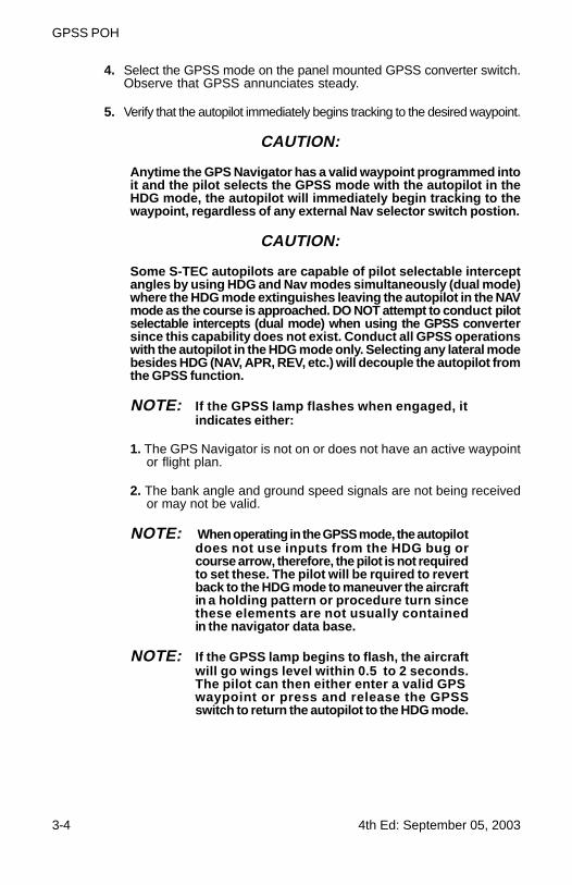
4. Select the GPSS mode on the panel mounted GPSS converter switch.Observe that GPSS annunciates steady.
5. Verify that the autopilot immediately begins tracking to the desired waypoint.
CAUTION:
Anytime the GPS Navigator has a valid waypoint programmed intoit and the pilot selects the GPSS mode with the autopilot in theHDG mode, the autopilot will immediately begin tracking to thewaypoint, regardless of any external Nav selector switch postion.
CAUTION:
Some S-TEC autopilots are capable of pilot selectable interceptangles by using HDG and Nav modes simultaneously (dual mode)where the HDG mode extinguishes leaving the autopilot in the NAVmode as the course is approached. DO NOT attempt to conduct pilotselectable intercepts (dual mode) when using the GPSS convertersince this capability does not exist. Conduct all GPSS operationswith the autopilot in the HDG mode only. Selecting any lateral modebesides HDG (NAV, APR, REV, etc.) will decouple the autopilot fromthe GPSS function.
NOTE: If the GPSS lamp flashes when engaged, itindicates either:
1. The GPS Navigator is not on or does not have an active waypointor flight plan.
2. The bank angle and ground speed signals are not being receivedor may not be valid.
NOTE: When operating in the GPSS mode, the autopilotdoes not use inputs from the HDG bug orcourse arrow, therefore, the pilot is not requiredto set these. The pilot will be rquired to revertback to the HDG mode to maneuver the aircraftin a holding pattern or procedure turn sincethese elements are not usually containedin the navigator data base.
NOTE: If the GPSS lamp begins to flash, the aircraftwill go wings level within 0.5 to 2 seconds.The pilot can then either enter a valid GPSwaypoint or press and release the GPSSswitch to return the autopilot to the HDG mode.
4th Ed: September 05, 2003 3-5
GPSS POH
3.2.2 GPS Approach Procedures
1. Select the HDG mode on the autopilot.
2. Select the HDG mode on the panel mounted GPSS converter switch.
3. Select and activate the desired approach on the GPS navigator.
4. Select the GPSS mode on the panel mounted GPSS converter switch.Observe that GPSS annunciates steady.
5. Verify that the autopilot immediately begins tracking to the desiredinitial approach fix.
6. If the selected approach contains a procedure turn or a holding pattern,the pilot must conduct the following procedure:
A. When approaching the procedure turn, deselect the GPSS modeby pressing the panel mounted switch, thus leaving the autopilotin HDG mode.
B. Lead the aircraft around the procedure turn or holding patternusing the HDG bug on the DG or HSI.
C. When approaching the desired inbound course, once againselect the GPSS mode.
D. Conduct the remainder of the approach in the GPSS mode.
7. Monitor course tracking quality during GPSS operations.
3.3 Emergency Procedures
In the event of a malfunction of the GPSS Converte,r or any time it is notperforming as expected, do not attempt to identify the system problem.Immediately regain control of the aircraft by disabling and disconnectingthe autopilot as necessary. Do not attempt to use the GPSS function untilthe problem has been identified and corrected.
NOTE: A GPSS unit malfunction will most likely affect theautopilots heading mode, rendering it unusable.However, it may be possible to use other autopilotlateral modes such as navigation (NAV) or approachand the pitch modes, if so equipped. Exercisecaution when examining the use of these functionsafter a GPSS malfunction.
3-6 4th Ed: September 05, 2003
GPSS POH
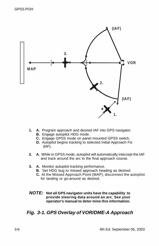
Fig. 3-1. GPS Overlay of VOR/DME-A Approach
M AP
3.
2.
1.*
(IA F)
VOR
(IA F)
1. A. Program approach and desired IAF into GPS navigator.B. Engage autopilot HDG mode.C. Engage GPSS mode on panel mounted GPSS switch.D. Autopilot begins tracking to selected Initial Approach Fix
(IAF).
2. A. While in GPSS mode, autopilot will automatically intercept the IAFand track around the arc to the final approach course.
3. A. Monitor autopilot tracking performance.B. Set HDG bug to missed approach heading as desired.C. At the Missed Approach Point (MAP), disconnect the autopilot
for landing or go-around as desired.
NOTE: Not all GPS navigator units have the capability toprovide steering data around an arc. See youroperator's manual to deter mine this information.
4th Ed: September 05, 2003 3-7
GPSS POH
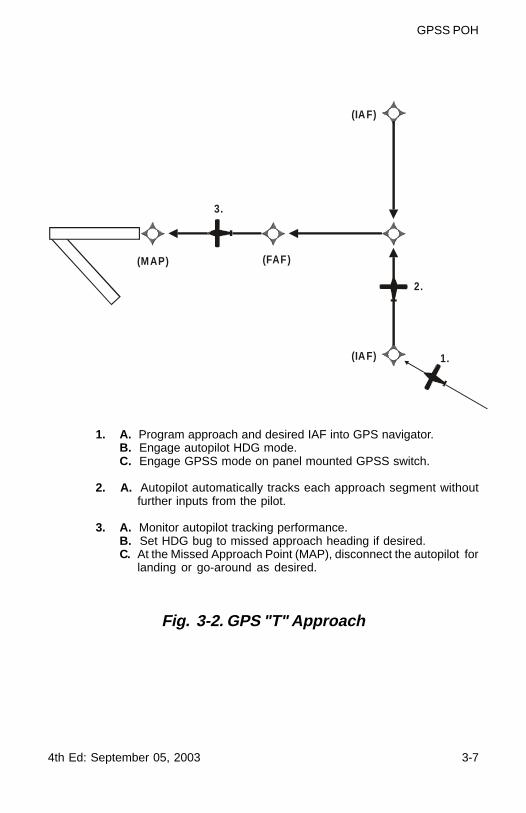
Fig. 3-2. GPS "T" Approach
(IAF)
1.
2.
3.
(MAP)
(IAF)
(FAF)
1. A. Program approach and desired IAF into GPS navigator.B. Engage autopilot HDG mode.C. Engage GPSS mode on panel mounted GPSS switch.
2. A. Autopilot automatically tracks each approach segment withoutfurther inputs from the pilot.
3. A. Monitor autopilot tracking performance.B. Set HDG bug to missed approach heading if desired.C. At the Missed Approach Point (MAP), disconnect the autopilot for
landing or go-around as desired.
3-8 4th Ed: September 05, 2003
GPSS POH
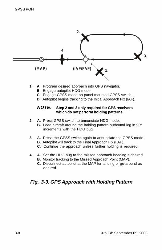
Fig. 3-3. GPS Approach with Holding Pattern
(IA F/FAF) 1.
2.
3.4.
(M AP)
1. A. Program desired approach into GPS navigator.B. Engage autopilot HDG mode.C. Engage GPSS mode on panel mounted GPSS switch.D. Autopilot begins tracking to the Initial Approach Fix (IAF).
NOTE: Step 2 and 3 only required for GPS receiverswhich do not perform holding patterns.
2. A. Press GPSS switch to annunciate HDG mode.B. Lead aircraft around the holding pattern outbound leg in 90º
increments with the HDG bug.
3. A. Press the GPSS switch again to annunciate the GPSS mode.B. Autopilot will track to the Final Approach Fix (FAF).C. Continue the approach unless further holding is required.
4. A. Set the HDG bug to the missed approach heading if desired.B. Monitor tracking to the Missed Approach Point (MAP).C. Disconnect autopilot at the MAP for landing or go-around as
desired.
4th Ed: September 05, 2003 3-9
GPSS POH
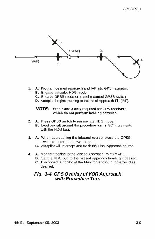
Fig. 3-4. GPS Overlay of VOR Approachwith Procedure Turn
(IA F/FAF)
1.
2.
3.4.
(M AP)
1. A. Program desired approach and IAF into GPS navigator.B. Engage autopilot HDG mode.C. Engage GPSS mode on panel mounted GPSS switch.D. Autopilot begins tracking to the Initial Approach Fix (IAF).
NOTE: Step 2 and 3 only required for GPS receiverswhich do not perform holding patterns.
2. A. Press GPSS switch to annunciate HDG mode.B. Lead aircraft around the procedure turn in 90º increments
with the HDG bug.
3. A. When approaching the inbound course, press the GPSSswitch to enter the GPSS mode.
B. Autopilot will intercept and track the Final Approach course.
4. A. Monitor tracking to the Missed Approach Point (MAP).B. Set the HDG bug to the missed approach heading if desired.C. Disconnect autopilot at the MAP for landing or go-around as
desired.

3-10 4th Ed: September 05, 2003
GPSS POH
Page Intentionally Blank
4th Ed: September 05, 2003 4-1
GPSS POH
SECTION 4APPENDICES

4-2 4th Ed: September 05, 2003
GPSS POH
Page Intentionally Blank
4th Ed: September 05, 2003 4-3
GPSS POH
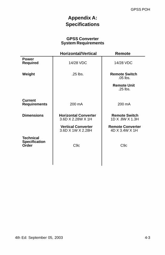
Appendix A:Specifications
GPSS ConverterSystem Requirements
Horizontal/Vertical RemotePowerRequired 14/28 VDC 14/28 VDC
Weight .25 lbs. Remote Switch .05 lbs.
Remote Unit .25 lbs.
CurrentRequirements 200 mA 200 mA
Dimensions Horizontal Converter Remote Switch 3.6D X 2.28W X 1H 1D X .8W X 1.3H
Vertical Converter Remote Converter 3.6D X 1W X 2.28H 4D X 3.4W X 1H
TechnicalSpecificationOrder C9c C9c

4-4 4th Ed: September 05, 2003
GPSS POH
Page Intentionally Blank

4th Ed: September 05, 2003 5-1
GPSS POH
SECTION 5GLOSSARY

5-2 4th Ed: September 05, 2003
GPSS POH
Page Intentionally Blank
4th Ed: September 05, 2003 5-3
GPSS POH
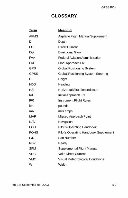
GLOSSARY
Term Meaning
AFMS Airplane Flight Manual Supplement
D Depth
DC Direct Current
DG Directional Gyro
FAA Federal Aviation Administration
FAF Final Approach Fix
GPS Global Positioning System
GPSS Global Positioning System Steering
H Height
HDG Heading
HSI Horizontal Situation Indicator
IAF Initial Approach Fix
IFR Instrument Flight Rules
lbs. pounds
mA milli amps
MAP Missed Approach Point
NAV Navigation
POH Pilot’s Operating Handbook
POHS Pilot's Operating Handbook Supplement
P/N Part Number
RDY Ready
SFM Supplemental Flight Manual
VDC Volts Direct Current
VMC Visual Meteorological Conditions
W Width

5-4 4th Ed: September 05, 2003
GPSS POH
Page Intentionally Blank

Meggitt Avionics/S-TECA Meggitt Aerospace Systems Company
One S-TEC Way · Municipal AirportMineral Wells, Texas 76067-9236 USA
Telephone 940/325-9406; FAX 940/325-39041-800-USA-STECwww.s-tec.com
Information in this document is subject to change without notice.©2002 S-TEC Corporation. All rights reserved. Printed in theUnited States of America. S-TEC and the S-TEC logo are registeredtrademarks of S-TEC Corporation.
P/N: 8799Date: 05 September 2003Printed in USA