Embed Size (px)
Citation preview

Global FRL and P3Y Series Air Preparation ProductsCatalog 0760P
ENGINEERING YOUR SUCCESS.
For inventory, lead times, and kit lookup, visit www.pdnplu.com
Parker Hannifi n CorporationPneumatic DivisionRichland, Michiganwww.parker.com/pneumatics
Air Preparation ProductsCatalog 0760P
Warning, Offer of Sale
! WARNINGFAILURE OR IMPROPER SELECTION OR IMPROPER USE OF THE PRODUCTS AND/OR SYSTEMS DESCRIBED HEREIN OR RELATED ITEMS CAN CAUSE DEATH, PERSONAL INJURY AND PROPERTY DAMAGE.This document and other information from Parker Hannifi n Corporation, its subsidiaries and authorized distributors provide product and/or system options for further investigation by users h aving technical expertise. It is important that you analyze all aspects of your application including consequences of any failure, and review the information concerning the product or system in the current product catalog. Due to the variety of operating conditions and applications for these products or systems, the user, through its own analysis and testing, is solely responsible for making the fi nal selection of the products and systems and assuring that all performance, safety and warning requirements of the application are met.The products described herein, including without limitation, product features, specifi cations, designs, availability and pricing, are subject to change by Parker Hannifi n Corporation and its subsidiaries at any time without notice.
Offer of SaleThe items described in this document are hereby offered for sale by Parker Hannifi n Corporation, its subsidiaries or its authorized distributors. This offer and its acceptance are governed by the provisions stated on the separate page of this document entitled “Offer of Sale”.
© Copyright 2016 Parker Hannifi n Corporation. All Rights Reserved

For inventory, lead time, and kit lookup, visit www.pdnplu.com
Parker Hannifi n CorporationPneumatic DivisionRichland, Michiganwww.parker.com/pneumatics
1
Air Preparation ProductsContents - www.parker.com/pneu/frl
Introduction 2 - 9
P31, P32, P33 Series 11 - 84
Global System 11
Particulate Filters 12- 17
Coalescing Filters 18 - 23
Regulators 24 - 35
Proportional Regulators 36 - 45
Filter / Regulators 46 - 53
Lubricators 54 - 59
Combinations 60 - 63
Dump Valves / Soft Start Valves 64 - 69
Redundant Safety Exhaust Valve 70 - 73
Accessories 74 - 84
P3Y Series 87 - 111
P3Y System 87
Particulate Filters 88 - 89
Coalescing Filters 90 - 91
Regulators 92 - 95
Proportional Pressure Regulators 96 - 97
Filter / Regulators 98 - 99
Lubricators 100 - 101
Combinations 102 - 103
Soft Start / Dump Valves 104 - 106
Accessories 107 - 111
Safety Guide 113 - 114
Offer of Sale 115
Catalog 0760P
Parker Pneumatic

For inventory, lead times, and kit lookup, visit www.pdnplu.com
Parker Hannifi n CorporationPneumatic DivisionRichland, Michiganwww.parker.com/pneumatics
2
Air Preparation ProductsAir Preparation
Catalog 0760P
Introduction
DECLARATION OF COMPLIANCE (ROHS)
European Directive 2011/65/EU – RoHS (Restriction us of certain
Hazardous Substances in electrical and electronic equipment),
restricts the use of the 6 substances in the manufacture of
specifi ed electrical equipment.
Lead: Product containing lead and its compound (except
for applications of lead as an alloying element by
weight in steel up to 0.35%, in aluminium up to 0.4%
and in copper alloys up to 4% and in circuit board
solder) must not exceed 0.1% by weight
Mercury: The concentration level must not exceed 0.1% by
volume
Cadmium: The concentration level must not exceed 0.01% by
volume
Hexavalent Chromiou:
This is a corrosive protective fi nish used on our
product line. Where this fi nish is utilized the Chromate
solution is Hexavalent (Chrome 6) free.
Polybrominated Biphenyls (PBB):
The concentration level must not exceed 0.1% by
weight. This substance is not know to be in any of
our products.
Polybrominated Diphenyl Esters (PBDE):
The concentration level must not exceed 0.1% by
weight. This substance is not know to be in any of
our products.
Following Ignition Hazard Assessments performed on the non-
electrical Global Air Preparation products they are in accordance
with the requirements of EN 13463-1:2009, it was considered that
the equipment does not contain its own source of ignition, and
therefore is not within the scope of directive 94/9/EC.
The products can be used in a Group II Category 2 environment
assuming that the ATEX Directive and the following conditions are
complied with:
• Installation and maintenance of the product must be undertaken
by qualifi ed personnel.
• Do not mount the products in an area where impact may occur.
• Filters must be used to limit the introduction of particles and to
capture particles generated in service.
• Supply air quality must be within ISO 8573-1:2010 Class 1.4.2.
• Maximum working temperature to be as stated on product
label.
• WARNING – pulsating pressure and/or a closed circuit can
generate heat.
• Deposits of dust on the product must not exceed
5mm thickness.
Refer to technical fi le for surface areas of plastics. The unit
must be earthed via the compressed air supply line.
• The unit must not come into contact with liquid solvents, acids
or alkalis
Refer to technical fi le for chemicals known to be
incompatible. Product cleaning must be undertaken using
a method complying with the specifi cations of the ATEX
zone, preferably by using mild soap and water or antistatic
products.
• Regulators, Filter Regulators:
Do not use Regulators or Filter Regulators within systems
that can create vibration within the Regulator / Filter
Regulator unit.
• Solenoid Operated Valves:
Are suitable for use in an ATEX environment, (Group II
Category 2) providing ATEX approved solenoids are fi tted.
• Technical fi le available on request.
Global Air Preparation products supplied by Parker Hannifi n
have been designed and manufactured in accordance with
“sound engineering practice”, as defi ned by Article 3 of Pressure
Equipment Directive 97/23/EC.
Global Air Preparation product range has been designed and
tested in accordance with ISO fl ow testing, envelope integrity, and
catalog data presented.
• Filters – ISO 5782-1 & ISO 5782-2: 1997
• Regulators- ISO 6953-1 & ISO 6953-2: 2000
• Lubricators- ISO 6301-1 & ISO 6301-2: 2009
Global Air Preparation product range is in compliance with REACH
to ensure continued compliance additions to the list of SVHC
(Substance of Very High Concern) are reviewed periodically.
Global Air Preparation product range has been third party Shock &
Vibration tested independently in accordance to EN 61373 : 1999,
Category 2
ATEXCOMPLIANT

For inventory, lead time, and kit lookup, visit www.pdnplu.com
Parker Hannifi n CorporationPneumatic DivisionRichland, Michiganwww.parker.com/pneumatics
3
Air Preparation ProductsAir Preparation
Catalog 0760P
Introduction
Parker’s Modular Air Preparation System
Full featured particulate and coalescing fi lters, regulators, fi lter/regulators, and lubricators are available with a wide range of standard options to meet air preparation needs.
Parker’s comprehensive Air Preparation System is available in four body sizes with different thread types to accommodate your requirements.
Individual units can easily be assembled into various combinations, utilizing patented modular lightweight body connectors.
www.parker.com
Global.Modular.Performance you need,wherever you need it.
For inventory, lead times, and kit lookup, visit www.pdnplu.com
Parker Hannifi n CorporationPneumatic DivisionRichland, Michiganwww.parker.com/pneumatics
4
Air Preparation ProductsAir Preparation
Catalog 0760P
Introduction
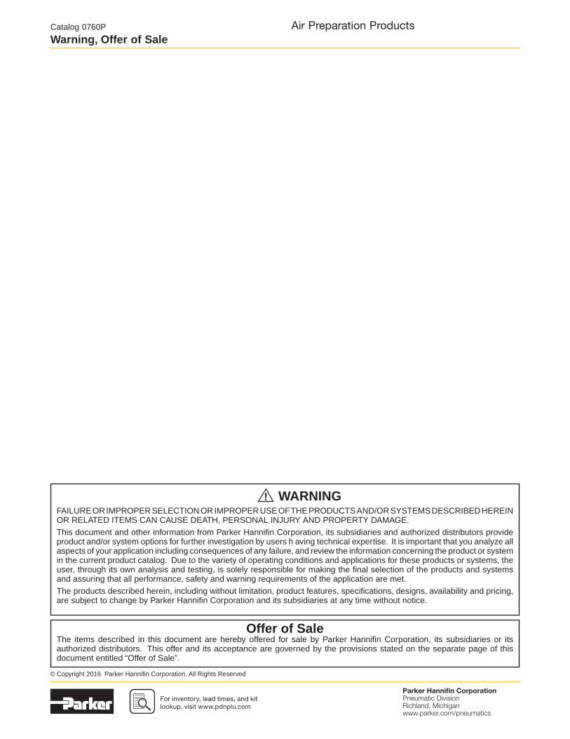
• 5μ particulate, 1.0μ and 0.01μ coalescing, and adsorber available as standard
• Transparent or metal bowl with manual or auto fl oat drains standard
• Available as stand alone,common port and electronic proportional
• Both relieving and non-relieving versions available
• Compact design for space savings
• Available with all the same standard options as the fi lters and regulators
• Proportional oil delivery over a wide range of air fl ows
• Fill under pressure
• Compact design for space savings
• Easily assembled
• Many confi gurations available
• Solenoid operated soft start, quick dump, and soft start/quick dump valves
• Manifold blocks
• Ball style lockout / shutoff valve
• Repair kits, gauges, etc.
Filters
Lubricators Combinations Accessories
Regulators Filter / Regulators
P32 Compact Series1/4", 3/8" and 1/2"60mm body width
P31 Mini Series1/4" ports
40mm body width
P33 Standard Series1/2" and 3/4"
73mm body width
Global Comprehensive Offering

For inventory, lead time, and kit lookup, visit www.pdnplu.com
Parker Hannifi n CorporationPneumatic DivisionRichland, Michiganwww.parker.com/pneumatics
5
Air Preparation ProductsAir Preparation
Catalog 0760P
Introduction
• 5μ particulate, 1.0μ and 0.01μ coalescing, and adsorber available as standard
• Polypropylene bowl with metal screw in bowl guard
• Available as a stand alonehigh fl ow unit with a rolling diaphragm to extend life
• Optional key lock
• Compact design for space savings
• Available with all the same standard options as the fi lters and regulators
• Proportional oil delivery over a wide range of air fl ows
• Fill under pressure
• Compact design for space savings
• Easily assembled
• Solenoid operated soft start, quick dump, and soft start/quick dump valves
• Manifold blocks
• Ball style lockout / shutoff valve
• Repair kits, gauges, etc.
Filters
Lubricators Combinations Accessories
Regulators Filter / Regulators
P3Y Series3/4" and 1"
90mm body width
P3Y Comprehensive Offering

For inventory, lead times, and kit lookup, visit www.pdnplu.com
Parker Hannifi n CorporationPneumatic DivisionRichland, Michiganwww.parker.com/pneumatics
6
Air Preparation ProductsAir Preparation
Catalog 0760P
Introduction
P31 Mini Series
P33 Standard Series
P32 Compact Series
P3Y Large Series
40mm body width
1/4" Ported
Flows up to: scfm (dm3/s, ANR)
Filter 25 (12)
Coalescer 7.5 (3.6)
Regulator 68 (32)
Filter/Regulator 22 (10)
Lubricator 52 (25)
Features:
• Space saving integral gauge
• Manifold style regulators available
• OSHA compliant shut-off valves
• Soft-Start & Quick Dump valves
• Electronic Proportional Regulator
60mm body width
1/4", 3/8", & 1/2" Ported
Flows up to: scfm (dm3/s, ANR)
Filter 82 (39)
Coalescer 36 (17)
Regulator 165 (78)
Filter/Regulator 136 (64)
Lubricator 90 (42)
Features:
• Manifold style regulators available
• OSHA Compliant shut-off valves
• Soft-Start & Quick Dump valves
• Electronic Proportional Regulator
90mm body width
3/4" and1" Ported
Flows up to: scfm (dm3/s, ANR)
Filter 170 (80)
Coalescer 307 (150)
Regulator 550 (260)
Filter/Regulator 465 (220)
Lubricator 390 (184)
Features:
• OSHA Compliant shut-off valves
• Soft-Start & Quick Dump valves
• Electronic Proportional Regulator
73mm body width
1/2" & 3/4" Ported
Flows up to: scfm (dm3/s, ANR)
Filter 85 (40)
Coalescer 72 (34)
Regulator 233 (111)
Filter/Regulator 230 (108)
Lubricator 150 (71)
Features:
• OSHA Compliant shut-off valves
• Soft-Start & Quick Dump valves
(Utilizes P32 size only)
• Electronic proportional regulator
(Utilizes P32 size only)
Air Preparation
For inventory, lead time, and kit lookup, visit www.pdnplu.com
Parker Hannifi n CorporationPneumatic DivisionRichland, Michiganwww.parker.com/pneumatics
7
Air Preparation ProductsAir Preparation
Catalog 0760P
Introduction
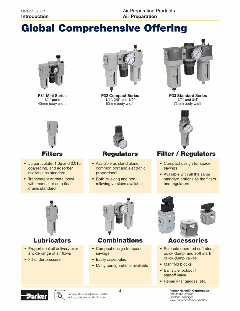
• Multiple output pressures (P2, P3, P4, etc.) with common inlet (P1)
• Available in two sizes P31 and P32
• Balanced valve design for accurate pressure regulation
• Outlet pressure ports in front and rear of unit.
• Multiple spring ranges available
• Electro-Pneumatic regulator
• Integrated systems control
• Accurate output pressure
• Micro parameter settings
• Selectable I/O parameters
• Quick, full fl ow exhaust
• LED display indicates output pressure
• Available in P32 compact series
• Fine adjustment sensitivity
• Good repeatability and minimal pressure drop
• Good fl ow capacity
• Light gray knob for easy identifi cation
• One facilitates the permanent tamperproofi ng of the Regulator and
Filter/Regulator units
• Hinged black part clamps over control knob and is locked in place
after sliding yellow cover over it
• Other allows for removable lockout/tagout tamperproofi ng
- Four pad lock location holes tagout
- Hinged locking clamp secures over existing knob via
yellow cover which is slid over into place
• T-Handle
• Preset and Tamperproof
P31P Mini Series P32P Compact Series
Additional Options P32 Only (Consult factory for availability)
Optional Tamperproof Kits
• Preset
• Pressure Limiter
• No air consumption in
steady state
• Multiple mounting options
• Protection to IP65
Semi Precision Regulator and Filter/Regulator
Electronic Proportional Regulator
Common Port Manifold Regulators
Complete Pneumatic System
P1
P1
P2P3
P4

For inventory, lead times, and kit lookup, visit www.pdnplu.com
Parker Hannifi n CorporationPneumatic DivisionRichland, Michiganwww.parker.com/pneumatics
8
Air Preparation ProductsAir Preparation
Catalog 0760P
Introduction
Fast cycle times, high product quality, and low downtime all require a clean, dry pneumatic system to function properly. Parker has what it takes to make sure pneumatic systems perform at their best.
As air is compressedto 7 bar (100 psig)
and higher, the relative humidity quickly
reaches 100% RH and air temperatures can
reach between110°C and 200°C (230°F and 392°F).
For every 11°C (20°F) that the air cools
after leaving the heat of the compressor,
50% of the moisture condenses into liquid
into the system.
The excess moisture condenses and
collects in the receiver tank and distribution
lines. This condensate must be removed.
Bulk liquid separators remove condensed
liquids after the aftercooler, receiver,
or anywhere within the distribution system.
Bulk liquid separators also help protect
downstream fi lters in the system where excess cooling takes
place.
Particulate fi lters are used for the removal
of solid particle contaminants down to
5 micron, as well asthe removal of
condensed liquids
Coalescing fi lters are designed to remove
water and oil aerosols (not vapor) and
particulate from air streams down to 0.01
micron in size.
Note: Water and oil, in vapor form, pass
through general purpose particulate
fi lters.
This type of fi lter should be used as a prefi lter for the coalescing (oilremoval) fi lter.
Installed in pairs, Particulate and
Coalescing fi lters ensure a continuous supply of high quality
air.
Key
Particulate
Oil
Water
Oil Vapor
Water Vapor
Together we can power your application with clean, dry air
Clean, dry pneumatic systems with
Parker Air Preparation
1Stage 2
3
4
5

For inventory, lead time, and kit lookup, visit www.pdnplu.com
Parker Hannifi n CorporationPneumatic DivisionRichland, Michiganwww.parker.com/pneumatics
9
Air Preparation ProductsAir Preparation
Catalog 0760P
Introduction
Refrigeration and desiccant dryers
lower the air’s dew point by removing
water vapor, providing appropriately dry air for the downstream
application.
Hydrocarbon and oil vapors are removed using fi lters utilizing activated carbon.
Airborne hydrocarbons are often left over from the compressor oils.
Refrigeration and desiccant dryers
lower the air’s dew point by removing
water vapor, providing appropriately dry air for the downstream
application.
Hydrocarbon and oil vapors are removed using fi lters utilizing activated carbon.
Airborne hydrocarbons are often left over from the compressor oils.
Stages
Function Air CompressorBulk Liquid
Removal
Particulate
Filtration
Coalescing
FiltrationAir Dryers
Hydrocarbon
Removal
ApplicationAll pneumatic
systems
Basic pneumatic
systems
Basic pneumatic
systems
Systems requiring
highest quality air.
Systems requiring
air with reduced
moisture content
Systems requiring
highest quality air for
critical applications
Description
Air leaving the
compressor room at
93ºC (200ºF) releases
95% of its moisture
into the piping
system when it cools
to 38ºC (100ºF)
Removes bulk
liquid contamination
and protects fi lters
where excess cooling
takes place in the
distribution piping
Removes solid
particulates down to
5 micron, and
the separation of
bulk contaminants.
Removes liquid
aerosols and
submicron
particulates (not
vapor) down to
0.01 micron.
Removes water
vapor from air
stream. Dew point
reduced down to 4ºC
(40ºF) (refrigeration)
or -40ºC (-40ºF)
(desiccant).
Removal of odors
and trace vapors for
critical applications.
Parker
Global Air
Preparation
Solution
Customer
supplied
P3TF
Bulk Liquid
Separator
P31, P32, P33, P3Y
Particulate Filter
P31, P32, P33, P3Y
Coalescing Filter
PRD Refrigeration
Dryer, DAS & PTW
Regenerative
Desiccant Dryer
P31, P32, P33, P3Y
Activated Carbon
(Adsorber) Filter
67
Clean
Dry Air
431 2 5 76

For inventory, lead times, and kit lookup, visit www.pdnplu.com
Parker Hannifi n CorporationPneumatic DivisionRichland, Michiganwww.parker.com/pneumatics
10
Air Preparation ProductsAir Preparation
Catalog 0760P
Introduction

For inventory, lead time, and kit lookup, visit www.pdnplu.com
Parker Hannifi n CorporationPneumatic DivisionRichland, Michiganwww.parker.com/pneumatics
11
Air Preparation ProductsGlobal Air Preparation
Catalog 0760P
Features
A completely modularair preparation system
Easy to adjust non-rising
knob with snap-lock,
preventing accidental
change of set pressure
Aluminum
body
NPT, BSPP or
BSPT porting
available
2-piece Patented
modular body
connector US Patent
number 5,383,689
Soft Start /
Dump Valve
Coalescing
Filter
Filter / Regulator
Ball Valve
Pressure
gauge
Quick release
bayonet-type
integral bowl
and bowl guard
assembly
Padlock
slideBowl guard
with multiple
viewing slots
Manual drain with
pipe-away, auto
drain available

For inventory, lead times, and kit lookup, visit www.pdnplu.com
Parker Hannifi n CorporationPneumatic DivisionRichland, Michiganwww.parker.com/pneumatics
12
Air Preparation ProductsGlobal Air Preparation
Catalog 0760P
Mini Particulate Filters
Ordering information:
• Integral 1/4" ports (NPT, BSPP & BSPT)
• High effi ciency 5 micron element as standard
• Excellent water removal effi ciency
• Robust but lightweight aluminum construction
• One hand operation for easy element cartridge removal
• Positive bayonet latch to ensure correct & safe fi tting
1 221
Manual drain Pulse drain
Port size Description ‡ Part number
1/4" Poly bowl, manual drain P31FB92EGMN
1/4" Poly bowl, pulse drain P31FB92EGBN
1/4" Metal bowl, manual drain P31FB92EMMN
1/4" Metal bowl, pulse drain P31FB92EMBN
Thread type
BSPP 1
BSPT 2
NPT 9
Mounting
N No bracket
Port size
1/4 2
Element
5µ Element E
Drain type
M Manual drain
B Pulse drain
X Flex drain
Bowl type
G Poly bowl with bowl guard
M Metal bowl without sight gauge
Basic series
Global modular mini
particulate fi lterP31FB
P31FB 9 2 E G M N
P31 Particulate Filter – Mini
Operating information
Supply pressure (max):
Plastic bowl 150 psig (10 bar)
Metal bowl 250 psig (17 bar)
Operating temperature:
Plastic bowl 14°F to 125°F (-10°C to 52°C)
Metal bowl 14°F to 150°F (-10°C to 65.5°C)
Standard fi ltration: 5 micron
Flow capacity*: 25 scfm (12 dm3/s, ANR)
Useful retention†: 0.4 US oz. (12 cm3)
Weight: 0.24 lb (0.11 kg)
* Inlet pressure 91.3 psig (6.3 bar). Pressure drop 4.9 psig (0.34 bar). † Useful retention refers to volume below the quiet zone baffl e.
Air quality:Within ISO 8573-1: 1991 Class 3 (Particulates)Within ISO 8573-1: 2001 Class 6 (Particulates)
‡ For polycarbonate bowl, see caution in Engineering Section A.
Most popular.

For inventory, lead time, and kit lookup, visit www.pdnplu.com
Parker Hannifi n CorporationPneumatic DivisionRichland, Michiganwww.parker.com/pneumatics
13
Air Preparation ProductsGlobal Air Preparation
Catalog 0760P
Mini Particulate Filters
Material Specifi cations
Body Aluminum
Body cap ABS
Plastic bowl Polycarbonate
Metal bowl Aluminum
Bowl guard Nylon
Element retainer Acetal
Baffl e Acetal
Filter element Sintered polyethylene
Seals Nitrile
Flow Charts
Repair and Service Kits
Plastic bowl / bowl guard, manual drain P31KB00BGM
Metal bowl / w/o sight gauge, manual drain P31KB00BMM
Plastic bowl / bowl guard, pulse drain P31KB00BGB
Metal bowl / w/o sight gauge, pulse drain P31KB00BMB
5µ particle fi lter element P31KA00ESE
C-bracket (fi ts to body) P31KA00MW
T-bracket with body connector P31KA00MT
Body connector P31KA00CB
P31FB 1/4" Filter
Manual Drain Pulse Drain
Pre
ssur
e D
rop
- (b
ar)
Pre
ssur
e D
rop
- (p
sig)
0
2
4
6
5
3
1
7
00
0
5 10 2015Flow - (dm3/s) n
Flow - (scfm)10 20 4030
0.1
0.2
0.3
0.4
0.5
1.6
23.2
Primary Pressure - bar
Primary Pressure - psig
4.0
58
6.3
91.4
10
145
1.58(40)
.79(20)
1.58(40)
.84(21.4)
4.91124.8)
4.71(119.6)
1.30(33)
5/32 (4mm)I.D. tubebarb fitting
Bowlremovalclearance
Inches (mm)

For inventory, lead times, and kit lookup, visit www.pdnplu.com
Parker Hannifi n CorporationPneumatic DivisionRichland, Michiganwww.parker.com/pneumatics
14
Port size Description ‡ Part number
1/4" Poly bowl, manual drain P32FB92EGMN
1/4" Poly bowl, auto drain P32FB92EGAN
1/4" Metal bowl, manual drain P32FB92ESMN
1/4" Metal bowl, auto drain P32FB92ESAN
3/8" Poly bowl, manual drain P32FB93EGMN
3/8" Poly bowl, auto drain P32FB93EGAN
3/8" Metal bowl, manual drain P32FB93ESMN
3/8" Metal bowl, auto drain P32FB93ESAN
1/2" Poly bowl, manual drain P32FB94EGMN
1/2" Poly bowl, auto drain P32FB94EGAN
1/2" Metal bowl, manual drain P32FB94ESMN
1/2" Metal bowl, auto drain P32FB94ESAN
• Integral 1/4", 3/8" or 1/2" ports (NPT, BSPP & BSPT)
• High effi ciency 5 micron element as standard
• Excellent water removal effi ciency
• Robust but lightweight aluminum construction
• Positive bayonet latch to ensure correct & safe fi tting
1 221
Manual drain Auto drain
Ordering Information:
Thread type
BSPP 1
BSPT 2
NPT 9
Mounting
N No bracket
Port size
1/4 2
3/8 3
1/2 4
Element
5µ Element E
Drain type
M Manual drain
A Auto drain
X Flex drain
Bowl type
G Poly bowl with bowl guard
M Metal bowl without sight gauge
S Metal bowl with sight gauge
Basic series
Global modular compact
particulate fi lterP32FB
P32FB 9 2 E G M N
Air Preparation ProductsGlobal Air Preparation
Catalog 0760P
Compact Particulate Filters
P32 Particulate Filter – Compact
Operating information
Supply pressure (max):
Plastic bowl 150 psig (10 bar)
Metal bowl 250 psig (17 bar)
Operating temperature:
Plastic bowl -13°F to 125°F (-25°C to 52°C)
Metal bowl -13°F to 150°F (-25°C to 65.5°C)
Standard fi ltration: 5 micron
Flow capacity*: 1/4 50 scfm (24 dm3/s, ANR)
3/8 78 scfm (37 dm3/s, ANR)
1/2 82 scfm (39 dm3/s, ANR)
Useful retention†: 1.7 US oz. (51 cm3)
Weight: 0.62 lb (0.28 kg)
* Inlet pressure 91.3 psig (6.3 bar). Pressure drop 4.9 psig (0.34 bar). † Useful retention refers to volume below the quiet zone baffl e.
Air quality:Within ISO 8573-1: 1991 Class 3 (Particulates)Within ISO 8573-1: 2001 Class 6 (Particulates)
‡ For polycarbonate bowl, see caution in Engineering Section A.
Most popular.

For inventory, lead time, and kit lookup, visit www.pdnplu.com
Parker Hannifi n CorporationPneumatic DivisionRichland, Michiganwww.parker.com/pneumatics
15
Flow ChartsMaterial Specifi cations
Body Aluminum
Body cap ABS
Plastic bowl Polycarbonate
Metal bowl Aluminum
Bowl guard Nylon
Defl ector Polypropylene
Element retainer / Baffl e Acetal
Filter element Sintered polyethylene
Seals Nitrile
Sight gauge Nylon
Repair and Service Kits
Plastic bowl / bowl guard, manual drain P32KB00BGM
Metal bowl / sight gauge, manual drain P32KB00BSM
Auto drain P32KA00DA
5µ particle fi lter element P32KA00ESE
L-bracket (fi ts to body) P32KA00ML
T-bracket (fi ts to body connector) P32KA00MB
T-bracket with body connector P32KA00MT
Body connector P32KA00CB
P32FB 1/4" Filter
P32FB 3/8" Filter
P32FB 1/2" Filter
Manual Drain Automatic Drain
Pre
ssur
e D
rop
- (b
ar)
Pre
ssur
e D
rop
- (p
sig)
0
2
4
6
5
3
1
7
00
0
10 20 40305 15 3525
Flow - (scfm)20 40 8060
0.1
0.2
0.3
0.4
0.5
2.5
36.2
Primary Pressure - bar
Primary Pressure - psig
6.3
91.4
10
145
Flow - (dm3/s) n
Pre
ssur
e D
rop
- (b
ar)
Pre
ssur
e D
rop
- (p
sig)
0
2
4
6
5
3
1
7
0
2.5
36.2
Primary Pressure - bar
Primary Pressure - psig
6.3
91.4
10
145
0
0
10 3020 40 60 807050
Flow - (scfm)20 40 60 80 100 120 140 160
0.1
0.2
0.3
0.4
0.5
Flow - (dm3/s) n
Pre
ssur
e D
rop
- (b
ar)
Pre
ssur
e D
rop
- (p
sig)
0
2
4
6
5
3
1
7
0
2.5
36.2
Primary Pressure - bar
Primary Pressure - psig
6.3
91.4
10
145
0
0
10 3020 40 60 7050
Flow - (scfm)20 40 60 80 100 120 140
0.1
0.2
0.3
0.4
0.5
Flow - (dm3/s) n
Air Preparation ProductsGlobal Air Preparation
Catalog 0760P
Compact Particulate Filters
2.36(60)
2.36(60)
1.04(26.3)
7.49(190.3)
7.26(184.3)
1.18(30)
2.28(58)
5/32 (4mm)I.D. tubebarb fitting
Bowlremovalclearance
Inches (mm)

For inventory, lead times, and kit lookup, visit www.pdnplu.com
Parker Hannifi n CorporationPneumatic DivisionRichland, Michiganwww.parker.com/pneumatics
16
Port size Description ‡ Part number
1/2" Poly bowl, manual drain P33FA94EGMN
1/2" Poly bowl, auto drain P33FA94EGAN
1/2" Metal bowl, manual drain P33FA94ESMN
1/2" Metal bowl, auto drain P33FA94ESAN
3/4" Poly bowl, manual drain P33FA96EGMN
3/4" Poly bowl, auto drain P33FA96EGAN
3/4" Metal bowl, manual drain P33FA96ESMN
3/4" Metal bowl, auto drain P33FA96ESAN
• Integral 1/2" or 3/4" ports (NPT, BSPP & BSPT)
• High effi ciency 5 micron element as standard
• Excellent water removal effi ciency
• Robust but lightweight aluminum construction
• Positive bayonet latch to ensure correct & safe fi tting
1 221
Manual drain Auto drain
Ordering Information:
Thread type
BSPP 1
BSPT 2
NPT 9
Mounting
N No bracket
Port size
1/2 4
3/4 6
Element
5µ Element E
Drain type
M Manual drain
A Auto drain
Bowl type
G Poly bowl with bowl guard
M Metal bowl without sight gauge
S Metal bowl with sight gauge
Basic series
Global modular standard
particulate fi lterP33FA
P33FA 9 6 E G M N
Air Preparation ProductsGlobal Air Preparation
Catalog 0760P
Standard Particulate Filters
P33 Particulate Filter – Standard
Operating information
Supply pressure (max):
Plastic bowl 150 psig (10 bar)
Metal bowl 250 psig (17 bar)
Operating temperature:
Plastic bowl -13°F to 125°F (-25°C to 52°C)
Metal bowl -13°F to 150°F (-25°C to 65.5°C)
Standard fi ltration: 5 micron
Flow capacity*: 1/2 85 scfm (40 dm3/s, ANR)
3/4 102 scfm (48 dm3/s, ANR)
Useful retention†: 2.8 US oz. (85 cm3)
Weight: 1.01 lb (0.46 kg)
* Inlet pressure 91.3 psig (6.3 bar). Pressure drop 4.9 psig (0.34 bar). † Useful retention refers to volume below the quiet zone baffl e.
Air quality:Within ISO 8573-1: 1991 Class 3 (Particulates)Within ISO 8573-1: 2001 Class 6 (Particulates)
‡ For polycarbonate bowl, see caution in Engineering Section A.
Most popular.

For inventory, lead time, and kit lookup, visit www.pdnplu.com
Parker Hannifi n CorporationPneumatic DivisionRichland, Michiganwww.parker.com/pneumatics
17
Pre
ssur
e D
rop
- (b
ar)
Pre
ssur
e D
rop
- (p
sig)
0
2
4
6
5
3
1
7
0
1.6
23.2
Primary Pressure - bar
Primary Pressure - psig
4.0
58
6.3
91.4
10
145
0
0
10 3020 40 60 7050
Flow - (scfm)20 40 60 80 100 120 140
0.1
0.2
0.3
0.4
0.5
Flow - (dm3/s) n
Pre
ssur
e D
rop
- (b
ar)
Pre
ssur
e D
rop
- (p
sig)
0
2
4
6
5
3
1
7
0
1.6
23.2
Primary Pressure - bar
Primary Pressure - psig
4.0
58
6.3
91.4
10
145
0
0
10 3020 40 60 807050
Flow - (scfm)20 40 60 80 100 120 140 160
0.1
0.2
0.3
0.4
0.5
Flow - (dm3/s) n
Flow ChartsMaterial Specifi cations
Body Aluminum
Body cap ABS
Plastic bowl Polycarbonate
Metal bowl Aluminum
Bowl guard Nylon
Defl ector Polypropylene
Element retainer / Baffl e Acetal
Filter element Sintered polyethylene
Seals Nitrile
Sight gauge Nylon
Repair and Service Kits
Plastic bowl / bowl guard, manual drain P33KA00BGM
Metal bowl / sight gauge, manual drain P33KA00BSM
Auto drain P32KA00DA
5µ particle fi lter element P33KA00ESE
L-bracket (fi ts to body) P33KA00ML
T-bracket (fi ts to body connector) P32KA00MB
T-bracket with body connector P33KA00MT
Body connector P32KA00CB
P33FA 3/4" Filter
P33FA 1/2" Filter
Manual Drain Automatic Drain
Air Preparation ProductsGlobal Air Preparation
Catalog 0760P
Standard Particulate Filters
2.87(73)
2.87(73)
1.02(26)
1.42(36)
8.39(213)
8.15(207)
5/32 (4mm)I.D. tubebarb fitting
Use 3/8" or (10mm) FlexTubing2.00
(51)
Bowlremovalclearance
Inches (mm)

For inventory, lead times, and kit lookup, visit www.pdnplu.com
Parker Hannifi n CorporationPneumatic DivisionRichland, Michiganwww.parker.com/pneumatics
18
Air Preparation ProductsGlobal Air Preparation
Catalog 0760P
Mini Coalescing and Adsorber Filters
• Integral 1/4" ports (NPT, BSPP & BSPT)
• Removes liquid aerosols and sub micron particles
• Oil free air for critical applications, such as air gauging,
pneumatic instrumentation and control
• Differential Pressure Indicator (DPI) standard on coalescing
fi lters
• Positive bayonet latch to ensure correct and safe fi tting
• Adsorbing activated carbon element removes oil vapors and
most hydrocarbons
Port size Description ‡ Element Part number
1/4" Poly bowl, manual drain 0.01 micron P31FB92DGMN
1/4' Poly bowl, pulse drain 0.01 micron P31FB92DGBN
1/4" Metal bowl, manual drain 0.01 micron P31FB92DMMN
1/4' Metal bowl, pulse drain 0.01 micron P31FB92DMBN
Note: To optimize the life of coalescing element, it is advisable to install a P31F pre-fi lter with a 5 micron element upstream of the coalescing fi lter.
To optimize the life of an Adsorber it is advisable to install a P31 Coalescing Filter upstream of the Adsorber. Adsorber element should be replaced approximately every 1000 hours of service.
Basic series
Global modular mini
coalescing fi lterP31FB
Thread type
BSPP 1
BSPT 2
NPT 9
Mounting
N No bracket
Element
0.01µ Element C
0.01µ Element with DPI D
1µ Element 9
1µ Element with DPI Q
Adsorber A
Bowl type
G Poly bowl with bowl guard
M Metal bowl without sight gauge
P31FB 9 2 D G M N
Port size
1/4 2
Drain type
B Pulse drain
M Manual drain
X Flex drain
Ordering Information:
P31 Coalescing and Adsorber Filters – Mini
Operating information
Supply pressure (max):
Poly bowl 150 psig (10 bar)
Metal bowl w/ DPI 150 psig (10 bar)
Metal bowl w/o DPI 250 psig (17 bar)
Operating temperature:
Plastic bowl 14°F to 125°F (-10°C to 52°C)
Metal bowl 14°F to 150°F (-10°C to 65.5°C)
Standard fi ltration: 1.0 and 0.01 micron
Adsorber Max. oil carryover (ppm w/w)
0.003 @ 70°F (21°C)
Flow capacity*:
1.0 micron coalescing 12 scfm (5.5 dm3/s, ANR)
0.01 micron coalescing 7.5 scfm (3.6 dm3/s, ANR)
Activated carbon adsorber 12.7 scfm (6 dm3/s, ANR)
Useful retention†: 0.4 US oz. (12 cm3)
Weight: 0.24 lb (0.11 kg)
* Inlet pressure 91.3 psig (6.3 bar). Pressure drop 3 psig (0.2 bar),
saturated element. † Useful retention refers to volume below the quiet zone baffl e.
‡ For polycarbonate bowl, see caution in Engineering Section A.
Most popular.

For inventory, lead time, and kit lookup, visit www.pdnplu.com
Parker Hannifi n CorporationPneumatic DivisionRichland, Michiganwww.parker.com/pneumatics
19
Air Preparation ProductsGlobal Air Preparation
Catalog 0760P
Mini Coalescing and Adsorber Filters
Material Specifi cations
Body Aluminum
Body cap ABS
Plastic bowl Polycarbonate
Metal bowl Aluminum
Filter element Borosilicate cloth
Adsorber element Activated carbon
Seals Nitrile
Flow Charts
Repair and Service Kits
Plastic bowl / bowl guard, manual drain P31KB00BGM
Metal bowl / w/o sight gauge ,manual drain P31KB00BMM
Plastic bowl / bowl guard, pulse drain P31KB00BGB
Metal bowl / w/o sight gauge, pulse drain P31KB00BMB
1µ coalescing fi lter element P31KA00ES9
0.01µ coalescing fi lter element P31KA00ESC
Activated carbon adsorber fi lter element P31KA00ESA
C-bracket (fi ts to body) P31KA00MW
T-bracket with body connector P31KA00MT
Body connector P31KA00CB
Differential pressure indicator (replacement) P31KB00RQ
P31FB - 1.0 micron fl ow
P31FB - 0.01 micron fl ow
Manual Drain Pulse Drain
Pre
ssur
e D
rop
- (b
ar)
Pre
ssur
e D
rop
- (p
sig)
0
2
4
6
5
3
1
7
00
0
21 43 5
Flow - (scfm)5 10
0.1
0.2
0.3
0.4
0.5
1.6
23.2
Primary Pressure - bar
Primary Pressure - psig
4.0
58
6.3
91.4
10
145
Flow - (dm3/s) n
SaturatedElementFlow
SaturatedElementFlow
Pre
ssur
e D
rop
- (b
ar)
Pre
ssur
e D
rop
- (p
sig)
0
2
4
6
5
3
1
7
0
1.6
23.2
Primary Pressure - bar
Primary Pressure - psig
4.0
58
6.3
91.4
10
145
0
0
21 43 5 7 86
Flow - (scfm)5 10 15
0.1
0.2
0.3
0.4
0.5
Flow - (dm3/s) n
1.58(40)
0.79(20)
1.58(40)
0.84(21.4)
4.91(124.8)
1.30(33)
0.48(12.1)
4.71(119.6)
0.48(12.1)
5/32 (4mm)I.D. tubebarb fitting
Bowlremovalclearance
Inches (mm)
For inventory, lead times, and kit lookup, visit www.pdnplu.com
Parker Hannifi n CorporationPneumatic DivisionRichland, Michiganwww.parker.com/pneumatics
20
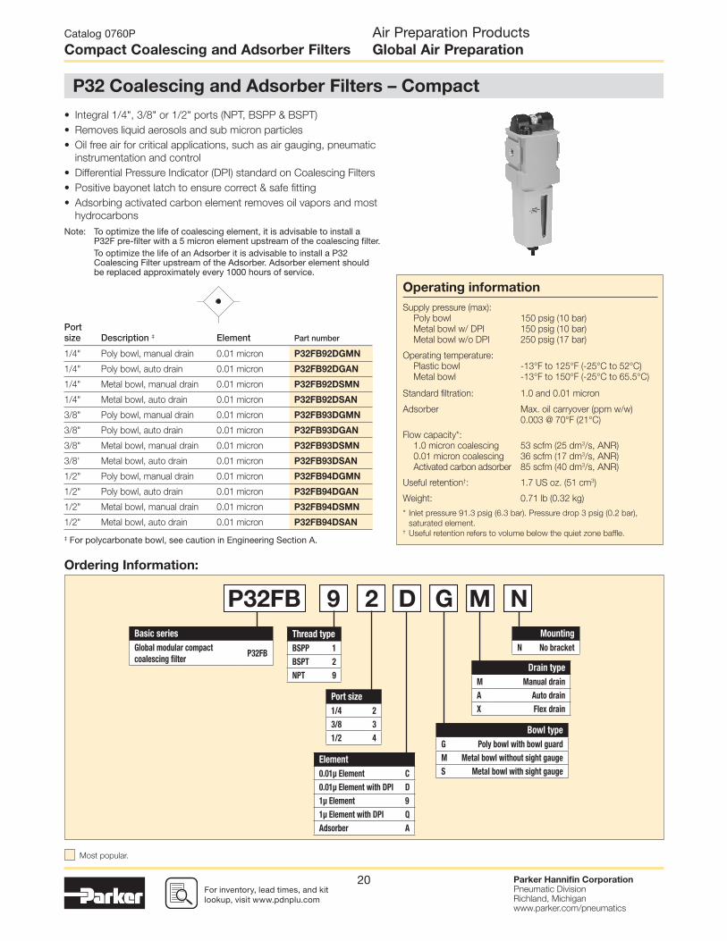
Port size Description ‡ Element Part number
1/4" Poly bowl, manual drain 0.01 micron P32FB92DGMN
1/4" Poly bowl, auto drain 0.01 micron P32FB92DGAN
1/4" Metal bowl, manual drain 0.01 micron P32FB92DSMN
1/4" Metal bowl, auto drain 0.01 micron P32FB92DSAN
3/8" Poly bowl, manual drain 0.01 micron P32FB93DGMN
3/8" Poly bowl, auto drain 0.01 micron P32FB93DGAN
3/8" Metal bowl, manual drain 0.01 micron P32FB93DSMN
3/8' Metal bowl, auto drain 0.01 micron P32FB93DSAN
1/2" Poly bowl, manual drain 0.01 micron P32FB94DGMN
1/2" Poly bowl, auto drain 0.01 micron P32FB94DGAN
1/2" Metal bowl, manual drain 0.01 micron P32FB94DSMN
1/2" Metal bowl, auto drain 0.01 micron P32FB94DSAN
• Integral 1/4", 3/8" or 1/2" ports (NPT, BSPP & BSPT)
• Removes liquid aerosols and sub micron particles
• Oil free air for critical applications, such as air gauging, pneumatic
instrumentation and control
• Differential Pressure Indicator (DPI) standard on Coalescing Filters
• Positive bayonet latch to ensure correct & safe fi tting
• Adsorbing activated carbon element removes oil vapors and most
hydrocarbons
Note: To optimize the life of coalescing element, it is advisable to install a P32F pre-fi lter with a 5 micron element upstream of the coalescing fi lter.
To optimize the life of an Adsorber it is advisable to install a P32 Coalescing Filter upstream of the Adsorber. Adsorber element should be replaced approximately every 1000 hours of service.
Basic series
Global modular compact
coalescing fi lterP32FB
Thread type
BSPP 1
BSPT 2
NPT 9
Mounting
N No bracket
Bowl type
G Poly bowl with bowl guard
M Metal bowl without sight gauge
S Metal bowl with sight gauge
P32FB 9 2 D G M N
Port size
1/4 2
3/8 3
1/2 4
Drain type
M Manual drain
A Auto drain
X Flex drain
Element
0.01µ Element C
0.01µ Element with DPI D
1µ Element 9
1µ Element with DPI Q
Adsorber A
Ordering Information:
Operating information
Supply pressure (max):
Poly bowl 150 psig (10 bar)
Metal bowl w/ DPI 150 psig (10 bar)
Metal bowl w/o DPI 250 psig (17 bar)
Operating temperature:
Plastic bowl -13°F to 125°F (-25°C to 52°C)
Metal bowl -13°F to 150°F (-25°C to 65.5°C)
Standard fi ltration: 1.0 and 0.01 micron
Adsorber Max. oil carryover (ppm w/w)
0.003 @ 70°F (21°C)
Flow capacity*:
1.0 micron coalescing 53 scfm (25 dm3/s, ANR)
0.01 micron coalescing 36 scfm (17 dm3/s, ANR)
Activated carbon adsorber 85 scfm (40 dm3/s, ANR)
Useful retention†: 1.7 US oz. (51 cm3)
Weight: 0.71 lb (0.32 kg)
* Inlet pressure 91.3 psig (6.3 bar). Pressure drop 3 psig (0.2 bar),
saturated element. † Useful retention refers to volume below the quiet zone baffl e.
Air Preparation ProductsGlobal Air Preparation
Catalog 0760P
Compact Coalescing and Adsorber Filters
P32 Coalescing and Adsorber Filters – Compact
‡ For polycarbonate bowl, see caution in Engineering Section A.
Most popular.

For inventory, lead time, and kit lookup, visit www.pdnplu.com
Parker Hannifi n CorporationPneumatic DivisionRichland, Michiganwww.parker.com/pneumatics
21
Flow ChartsMaterial Specifi cations
Body Aluminum
Body cap ABS
Plastic bowl Polycarbonate
Metal bowl Aluminum
Filter element Borosilicate cloth
Adsorber Activated carbon
Seals Nitrile
Sight gauge Nylon
Repair and Service Kits
Plastic bowl / bowl guard, manual drain P32KB00BGM
Metal bowl / sight gauge, manual drain P32KB00BSM
Auto drain P32KA00DA
1µ coalescing fi lter element P32KA00ES9
0.01µ coalescing fi lter element P32KA00ESC
Activated carbon adsorber fi lter element P32KA00ESA
L-bracket (fi ts to body) P32KA00ML
T-bracket (fi ts to body connector) P32KA00MB
T-bracket with body connector P32KA00MT
Body connector P32KA00CB
Differential pressure indicator (replacement) P32KA00RQ
P32FB - 1.0 micron fl ow
P32FB - 0.01 micron fl ow
Manual Drain Automatic Drain
SaturatedElementFlow
Pre
ssur
e D
rop
- (b
ar)
Pre
ssur
e D
rop
- (p
sig)
0
2
4
6
5
3
1
7
0
2.5
36.3
Primary Pressure - bar
Primary Pressure - psig10
145
6.3
91.4
0
0
2010 4030 50
Flow - (scfm)20 40 60 80 100
0.1
0.2
0.3
0.4
0.5
Flow - (dm3/s) n
SaturatedElementFlow
Pre
ssur
e D
rop
- (b
ar)
Pre
ssur
e D
rop
- (p
sig)
0
2
4
6
5
3
1
7
0
2.5
36.3
Primary Pressure - bar
Primary Pressure - psig
6.3
91.4
10
145
0
0
2010 40 6050 7030
Flow - (scfm)20 40 60 80 100 120 140
0.1
0.2
0.3
0.4
0.5
Flow - (dm3/s) n
Air Preparation ProductsGlobal Air Preparation
Catalog 0760P
Compact Coalescing and Adsorber Filters
2.36(60)
2.36(60)
1.90(48.3)
8.36(212.3)
8.12(206.3)
1.18(30)
2.28(58)
Bowlremovalclearance
Inches (mm)
5/32 (4mm)I.D. tubebarb fitting

For inventory, lead times, and kit lookup, visit www.pdnplu.com
Parker Hannifi n CorporationPneumatic DivisionRichland, Michiganwww.parker.com/pneumatics
22
Port size Description ‡ Element Part number
1/2" Poly bowl, manual drain 0.01 micron P33FA94DGMN
1/2" Poly bowl, auto drain 0.01 micron P33FA94DGAN
1/2" Metal bowl, manual drain 0.01 micron P33FA94DSMN
1/2" Metal bowl, auto drain 0.01 micron P33FA94DSAN
3/4" Poly bowl, manual drain 0.01 micron P33FA96DGMN
3/4" Poly bowl, auto drain 0.01 micron P33FA96DGAN
3/4" Metal bowl, manual drain 0.01 micron P33FA96DSMN
3/4" Metal bowl, auto drain 0.01 micron P33FA96DSAN
• Integral 1/2" or 3/4" ports (NPT, BSPP & BSPT)
• Removes liquid aerosols and sub micron particles
• Oil free air for critical applications, such as air gauging, pneumatic
instrumentation and control
• Differential Pressure Indicator (DPI) standard on Coalescing Filters
• Positive bayonet latch to ensure correct & safe fi tting
• Adsorbing activated carbon element removes oil vapors
and most hydrocarbons
Note: To optimize the life of coalescing element, it is advisable to install a P33F pre-fi lter with a 5 micron element upstream of the coalescing fi lter.
To optimize the life of an Adsorber it is advisable to install a P33 Coalescing Filter upstream of the Adsorber. Adsorber element should be replaced approximately every 1000 hoursof service.
Basic series
Global modular standard
coalescing fi lterP33FA
Thread type
BSPP 1
BSPT 2
NPT 9
Mounting
N No bracket
Bowl type
G Poly bowl with bowl guard
M Metal bowl without sight gauge
S Metal bowl with sight gauge
P33FA 9 6 D G M N
Port size
1/2 4
3/4 6
Drain type
M Manual drain
A Auto drain
Element
0.01µ Element C
0.01µ Element with DPI D
1µ Element 9
1µ Element with DPI Q
Adsorber A
Operating information
Supply pressure (max):
Poly bowl 150 psig (10 bar)
Metal bowl w/ DPI 150 psig (10 bar)
Metal bowl w/o DPI 250 psig (17 bar)
Operating temperature:
Plastic bowl -13°F to 125°F (-25°C to 52°C)
Metal bowl -13°F to 150°F (-25°C to 65.6°C)
Standard fi ltration: 1.0 and 0.01 micron
Adsorber Max. oil carryover (ppm w/w)
0.003 @ 70°F (21°C)
Flow capacity*: 1.0 micron coalescing 68 scfm (32 dm3/s, ANR)
0.01 micron coalescing 42 scfm (20 dm3/s, ANR)
Activated carbon adsorber 72 scfm (34 dm3/s, ANR)
Useful retention†: 2.8 US oz. (85 cm3)
Weight: 1.10 lb (0.50 kg)
* Inlet pressure 91.3 psig (6.3 bar). Pressure drop 3 psig (0.2 bar),
saturated element. † Useful retention refers to volume below the quiet zone baffl e.
Ordering information:
Air Preparation ProductsGlobal Air Preparation
Catalog 0760P
Standard Coalescing and Adsorber Filters
P33 Coalescing and Adsorber Filters – Standard
‡ For polycarbonate bowl, see caution in Engineering Section A.
Most popular.

For inventory, lead time, and kit lookup, visit www.pdnplu.com
Parker Hannifi n CorporationPneumatic DivisionRichland, Michiganwww.parker.com/pneumatics
23
Flow ChartsMaterial Specifi cations
Body Aluminum
Body cap ABS
Plastic bowl Polycarbonate
Metal bowl Aluminum
Filter element Borosilicate cloth
Adsorber Activated carbon
Seals Nitrile
Sight gauge Nylon
Repair and Service Kits
Plastic bowl / bowl guard, manual drain P33KA00BGM
Metal bowl / sight gauge, manual drain P33KA00BSM
Auto drain P32KA00DA
1µ coalescing fi lter element P33KA00ES9
0.01µ coalescing fi lter element P33KA00ESC
Activated carbon adsorber fi lter element P33KA00ESA
L-bracket (fi ts to body) P33KA00ML
T-bracket (fi ts to body connector) P32KA00MB
T-bracket with body connector P32KA00MT
Body connector P32KA00CB
Differential pressure indicator (replacement) P32KA00RQ
SaturatedElementFlow
Pre
ssur
e D
rop
- (b
ar)
Pre
ssur
e D
rop
- (p
sig)
0
2
4
6
5
3
1
7
0
2.0
29
Primary Pressure - bar
Primary Pressure - psig
4.0
58
6.3
91.4
0.1
0.2
0.3
0.4
0.5
0
0
10 20 504030
Flow - (scfm)20 40 60 80 100
Flow - (dm3/s) n
SaturatedElementFlow
Pre
ssur
e D
rop
- (b
ar)
Pre
ssur
e D
rop
- (p
sig)
0
2
4
6
5
3
1
7
0
2.0
29
Primary Pressure - bar
Primary Pressure - psig
4.0
58
6.3
91.4
0.1
0.2
0.3
0.4
0.5
Flow - (scfm)
0
0
10 20 4030
20 40 60 80
Flow - (dm3/s) n
P33FA - 1.0 micron fl ow
P33FA - 0.01 micron fl ow
Manual Drain Automatic Drain
Air Preparation ProductsGlobal Air Preparation
Catalog 0760P
Standard Coalescing and Adsorber Filters
2.87(73)
DPI
1.02(26)
2.87(73)
1.42(36)
9.25(235)
9.02(229)
Use 3/8" or 10mm FlexTubing2.00
(51)
5/32 (4mm)I.D. tubebarb fitting Bowl
removalclearance
Inches (mm)
For inventory, lead times, and kit lookup, visit www.pdnplu.com
Parker Hannifi n CorporationPneumatic DivisionRichland, Michiganwww.parker.com/pneumatics
24
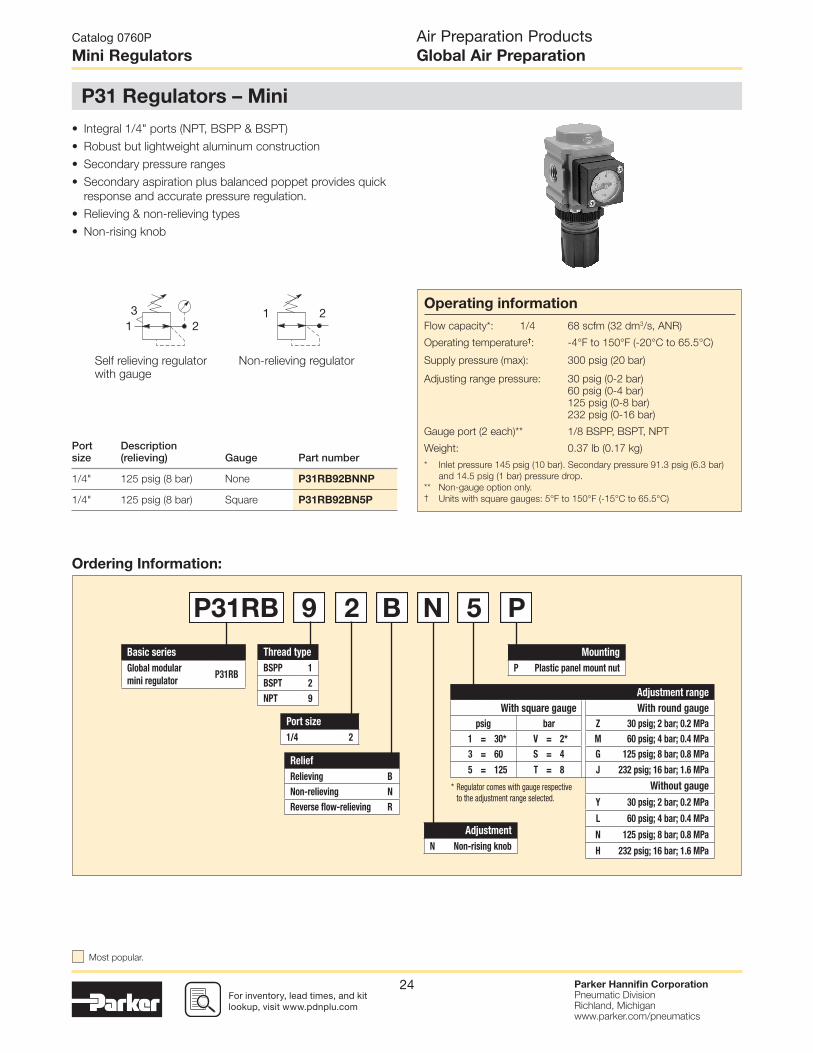
• Integral 1/4" ports (NPT, BSPP & BSPT)
• Robust but lightweight aluminum construction
• Secondary pressure ranges
• Secondary aspiration plus balanced poppet provides quick
response and accurate pressure regulation.
• Relieving & non-relieving types
• Non-rising knob
Self relieving regulatorwith gauge
Non-relieving regulator
1 213
2
Port size
Description (relieving) Gauge Part number
1/4" 125 psig (8 bar) None P31RB92BNNP
1/4" 125 psig (8 bar) Square P31RB92BN5P
Basic series
Global modular
mini regulator P31RB
Thread type
BSPP 1
BSPT 2
NPT 9
Mounting
P Plastic panel mount nut
Relief
Relieving B
Non-relieving N
Reverse fl ow-relieving R
P31RB 9 2 B N 5 P
Port size
1/4 2
Adjustment range
With square gauge With round gauge
psig bar Z 30 psig; 2 bar; 0.2 MPa
1 = 30* V = 2* M 60 psig; 4 bar; 0.4 MPa
3 = 60 S = 4 G 125 psig; 8 bar; 0.8 MPa
5 = 125 T = 8 J 232 psig; 16 bar; 1.6 MPa
Without gauge
Y 30 psig; 2 bar; 0.2 MPa
L 60 psig; 4 bar; 0.4 MPa
N 125 psig; 8 bar; 0.8 MPa
H 232 psig; 16 bar; 1.6 MPa
* Regulator comes with gauge respective to the adjustment range selected.
Adjustment
N Non-rising knob
Ordering Information:
Air Preparation ProductsGlobal Air Preparation
Catalog 0760P
Mini Regulators
P31 Regulators – Mini
Operating information
Flow capacity*: 1/4 68 scfm (32 dm3/s, ANR)
Operating temperature†: -4°F to 150°F (-20°C to 65.5°C)
Supply pressure (max): 300 psig (20 bar)
Adjusting range pressure: 30 psig (0-2 bar)
60 psig (0-4 bar)
125 psig (0-8 bar)
232 psig (0-16 bar)
Gauge port (2 each)** 1/8 BSPP, BSPT, NPT
Weight: 0.37 lb (0.17 kg)
* Inlet pressure 145 psig (10 bar). Secondary pressure 91.3 psig (6.3 bar)
and 14.5 psig (1 bar) pressure drop.
** Non-gauge option only.† Units with square gauges: 5°F to 150°F (-15°C to 65.5°C)
Most popular.

For inventory, lead time, and kit lookup, visit www.pdnplu.com
Parker Hannifi n CorporationPneumatic DivisionRichland, Michiganwww.parker.com/pneumatics
25
Material Specifi cations Body Aluminum
Adjustment knob Acetal
Bonnet PBT
Diaphragm assembly Brass / Nitrile
Valve assembly Brass / Nitrile
Springs Steel
Seals Nitrile
Panel nut Acetal
CAUTION:REGULATOR PRESSURE ADJUSTMENT – The working range of knob adjustment is designed to permit outlet pressures within their full range. Pressure adjustment beyond this range is also possible because the knob is not a limiting device. This is a common characteristic of most industrial regulators, and limiting devices may be obtained only by special design. For best performance, regulated pressure should always be set by increasing the pressure up to the desired setting.
WARNING
Product rupture can cause serious injury.Do not connect regulator to bottled gas.
Do not exceed Maximum primary pressure rating.
!
Flow Charts
Repair and Service Kits
Diaphagm repair kit - relieving P31KB00RB
Diaphagm repair kit - non-relieving P31KB00RC
Panel mount nut - aluminum P31KA00MM
Panel mount nut - plastic P31KA00MP
Angle bracket (attaches via panel nut) P31KB00MR
C-bracket (fi ts to body) P31KA00MW
T-bracket with body connector P31KA00MT
Body connector P31KA00CB
Gauges
Square fl ush mount gauge
0-4 bar K4511SCR04B
0-11 bar K4511SCR11B
0-60 psig K4511SCR060
0-160 psig K4511SCR160
Square with adapter kit
0-4 bar P6G-PR10040
0-11 bar P6G-PR10110
0-60 psig P6G-PR90060
0-160 psig P6G-PR90160
1.00" Round 1/8" center back mount
0-60 psig / 0-4 bar K4510N18060
0-160 psig / 0-11 bar K4510N18160
40mm Round 1/8" center back mount(Not for use with common
port regulators)
0-30 psig / 0-2 bar K4515N18030
0-60 psig / 0-4 bar K4515N18060
0-160 psig / 0-11 bar K4515N18160
For best performance, regulated pressure should always be set by increasing the
pressure up to the desired setting.
P31RB 1/4" Regulator
Inlet Pressure - 10 bar (145 psig)
Sec
onda
ry P
ress
ure
- (b
ar)
Sec
onda
ry P
ress
ure
- (p
sig)
0
20
40
60
80
100
120
140
2.5 bar
36.3 psig
8.0 bar
116 psig
4.0 bar
58 psig
6.3 bar
91.4 psig
0
2
3
4
5
6
7
8
9
10
1
0
0
105 15 25 3520 4030
Flow - (scfm)20 4010 30 60 8050 70
Flow - (dm3/s) n
Air Preparation ProductsGlobal Air Preparation
Catalog 0760P
Mini Regulators
1.20(30.6)
2.24(56.8)
1.58(40)
1.58(40)
2.41(61.3)
0.79(20)
SquareGauge
3.00(76.3)
RoundGauge
4.10(104.1)
Inches (mm)
NOTE: 1.20 in. (30mm) hole required for panel nut mounting.

For inventory, lead times, and kit lookup, visit www.pdnplu.com
Parker Hannifi n CorporationPneumatic DivisionRichland, Michiganwww.parker.com/pneumatics
26
• Manifold style regulator with line pressure on both sides
• Pressure output is at front or rear
• Inlet port 1/4" (NPT, BSPP & BSPT)
• Working port 1/8"
• Robust construction
• Secondary pressure ranges
• Secondary aspiration plus balanced poppet provides quick
response and accurate pressure regulation
• Relieving & non-relieving types
• Non-rising knob
Self relieving regulatorwith gauge
Non-relieving regulator
1 213
2
Basic series
Global modular mini
common regulator P31HB
Thread type
BSPP 1
BSPT 2
NPT 9
Mounting
P Plastic panel mount nut
P31HB 9 2 B N 5 P
Port size †
1/4 2
Adjustment range
With square gauge With round gauge
psig bar Z 30 psig; 2 bar; 0.2 MPa
1 = 30* V = 2* M 60 psig; 4 bar; 0.4 MPa
3 = 60 S = 4 G 125 psig; 8 bar; 0.8 MPa
5 = 125 T = 8 J 232 psig; 16 bar; 1.6 MPa
Without gauge
Y 30 psig; 2 bar; 0.2 MPa
L 60 psig; 4 bar; 0.4 MPa
N 125 psig; 8 bar; 0.8 MPa
H 232 psig; 16 bar; 1.6 MPa
† Working port 1/8".
P2
P2P2
P2
P1
P1
P1
P2 P2 P2 P2
Adjustment
N Non-rising knob
Relief
Relieving B
Non-relieving N
Reverse fl ow-relieving R
Port size
Description (relieving) Gauge Part number
1/4" 125 psig (8 bar) None P31HB92BNNP
1/4" 125 psig (8 bar) Square P31HB92BN5P
Ordering Information:
Air Preparation ProductsGlobal Air Preparation
Catalog 0760P
Mini Common P1 Regulators
P31 Common P1 Regulators – Mini
Operating information
Flow capacity*:
1/4 42 scfm (20 dm3/s, ANR)
Operating temperature: -4°F to 150°F (-20°C to 65.5°C)
Supply pressure (max): 300 psig (20 bar)
Adjusting range pressure: 30 psig (0-2 bar)
60 psig (0-4 bar)
125 psig (0-8 bar)
232 psig (0-16 bar)
P1 port size (inlet/outlet) 1/4 NPT, BSPP, BSPT
P2 regulated ports (2 ea.) 1/8 NPT, BSPP, BSPT
Weight: 0.66 lb (0.30 kg)
* Inlet pressure 145 psig (10 bar). Secondary pressure 91.3 psig (6.3 bar)
and 14.5 psig (1 bar) pressure drop.
* Regulator comes with gauge respective to the adjustment range selected.
Most popular.
For inventory, lead time, and kit lookup, visit www.pdnplu.com
Parker Hannifi n CorporationPneumatic DivisionRichland, Michiganwww.parker.com/pneumatics
27
NOTE: 1.20 in. (30mm) hole required for panel nut mounting.
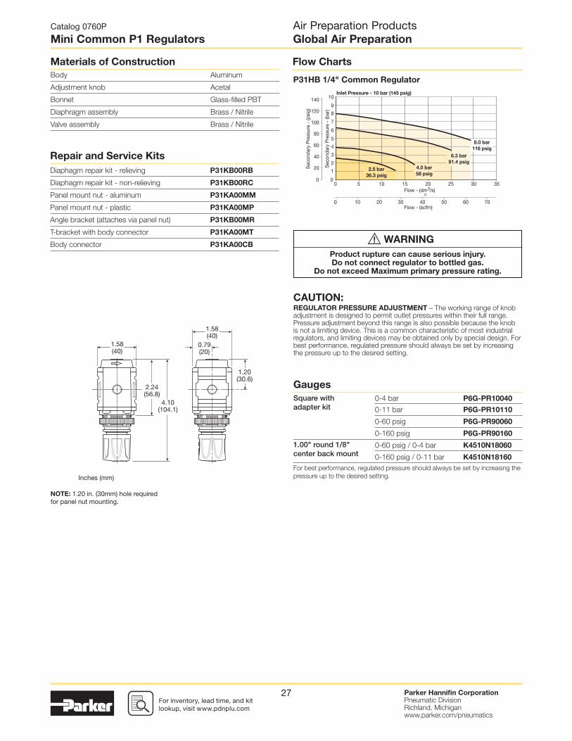
Materials of Construction
Body Aluminum
Adjustment knob Acetal
Bonnet Glass-fi lled PBT
Diaphragm assembly Brass / Nitrile
Valve assembly Brass / Nitrile
Flow Charts
P31HB 1/4" Common Regulator
Repair and Service Kits
Diaphagm repair kit - relieving P31KB00RB
Diaphagm repair kit - non-relieving P31KB00RC
Panel mount nut - aluminum P31KA00MM
Panel mount nut - plastic P31KA00MP
Angle bracket (attaches via panel nut) P31KB00MR
T-bracket with body connector P31KA00MT
Body connector P31KA00CB
Inlet Pressure - 10 bar (145 psig)
Sec
onda
ry P
ress
ure
- (b
ar)
Sec
onda
ry P
ress
ure
- (p
sig)
0
20
40
60
80
100
120
140
2.5 bar
36.3 psig
8.0 bar
116 psig
4.0 bar
58 psig
6.3 bar
91.4 psig
0
2
3
4
5
6
7
8
9
10
1
0
0
105 15 25 3520 30
Flow - (scfm)20 4010 30 6050 70
Flow - (dm3/s) n
Gauges
Square with adapter kit
0-4 bar P6G-PR10040
0-11 bar P6G-PR10110
0-60 psig P6G-PR90060
0-160 psig P6G-PR90160
1.00" round 1/8" center back mount
0-60 psig / 0-4 bar K4510N18060
0-160 psig / 0-11 bar K4510N18160
For best performance, regulated pressure should always be set by increasing the
pressure up to the desired setting.
Air Preparation ProductsGlobal Air Preparation
Catalog 0760P
Mini Common P1 Regulators
CAUTION:REGULATOR PRESSURE ADJUSTMENT – The working range of knob adjustment is designed to permit outlet pressures within their full range. Pressure adjustment beyond this range is also possible because the knob is not a limiting device. This is a common characteristic of most industrial regulators, and limiting devices may be obtained only by special design. For best performance, regulated pressure should always be set by increasing the pressure up to the desired setting.
1.58(40)
1.58(40)
Inches (mm)
1.20(30.6)
2.24(56.8)
0.79(20)
4.10(104.1)
WARNING
Product rupture can cause serious injury.Do not connect regulator to bottled gas.
Do not exceed Maximum primary pressure rating.
!

For inventory, lead times, and kit lookup, visit www.pdnplu.com
Parker Hannifi n CorporationPneumatic DivisionRichland, Michiganwww.parker.com/pneumatics
28
Self relieving regulatorwith gauge
Non-relieving regulator
1 213
2
• Integral 1/4", 3/8" or 1/2" ports (NPT, BSPP & BSPT)
• Robust but lightweight aluminum construction
• Secondary pressure ranges
• Secondary aspiration plus balanced poppet provides quick
response and accurate pressure regulation
• Relieving & non-relieving types
• Non-rising knob
• Available T-handle
Port size
Description (relieving) Gauge Part number
1/4" 125 psig (8 bar) None P32RB92BNNP
1/4" 125 psig (8 bar) Round P32RB92BNGP
3/8" 125 psig (8 bar) None P32RB93BNNP
3/8" 125 psig (8 bar) Round P32RB93BNGP
1/2" 125 psig (8 bar) None P32RB94BNNP
1/2" 125 psig (8 bar) Round P32RB94BNGP
Basic series
Global modular
compact regulatorP32RB
Thread type
BSPP 1
BSPT 2
NPT 9
Mounting
P Plastic panel mount nut
Relief
Relieving B
Non-relieving N
P32RB 9 2 B N G P
Port size
1/4 2
3/8 3
1/2 4
Adjustment range
With square gauge With round gauge
psig bar Z 30 psig; 2 bar; 0.2 MPa
1 = 30* V = 2* M 60 psig; 4 bar; 0.4 MPa
3 = 60 S = 4 G 125 psig; 8 bar; 0.8 MPa
5 = 125 T = 8 J 250 psig; 17 bar; 1.7 MPa
Without gauge
Y 30 psig; 2 bar; 0.2 MPa
L 60 psig; 4 bar; 0.4 MPa
N 125 psig; 8 bar; 0.8 MPa
H 250 psig; 17 bar; 1.7 MPa
Adjustment
N Non-rising knob
T T-Handle
Ordering Information:
Air Preparation ProductsGlobal Air Preparation
Catalog 0760P
Compact Regulators
P32 Regulators – Compact
Operating information
Flow capacity*:
1/4 148 scfm (70 dm3/s, ANR)
3/8, 1/2 165 scfm (78 dm3/s, ANR)
Operating temperature: -13°F to 150°F (-25°C to 65.5°C)
Supply pressure (max): 300 psig (20 bar)
Adjusting range pressure: 30 psig (0-2 bar)
60 psig (0-4 bar)
125 psig (0-8 bar)
250 psig (0-17 bar)
Gauge port (2 each) 1/4 NPT, BSPP, BSPT
Weight: 0.90 lb (0.41 kg)
* Inlet pressure 145 psig (10 bar). Secondary pressure 91.3 psig (6.3 bar)
and 14.5 psig (1 bar) pressure drop.
* Regulator comes with gauge respective to the adjustment range selected.
Most popular.

For inventory, lead time, and kit lookup, visit www.pdnplu.com
Parker Hannifi n CorporationPneumatic DivisionRichland, Michiganwww.parker.com/pneumatics
29
Flow ChartsMaterial Specifi cations
Body Aluminum
Adjustment knob Acetal
Bonnet Glass-fi lled nylon
Diaphragm assembly Nitrile / Zinc
Valve assembly Brass / Nitrile
Springs Steel, stainless steel
Seals Nitrile
Panel nut Acetal
Repair and Service Kits
Diaphagm repair kit - relieving P32KB00RB
Diaphagm repair kit - non-relieving P32KB00RC
Panel mount nut - aluminum P32KA00MM
Panel mount nut - plastic P32KA00MP
Angle bracket (attaches via panel nut) P32KB00MR
T-bracket with body connector P32KA00MT
T-bracket P32KA00MB
Body connector P32KA00CB
P32RB 3/8" Regulator
P32RB 1/2" Regulator
P32RB 1/4" Regulator
NOTE: 1.90 in. (48mm) hole
required for panel nut mounting.
Inlet Pressure - 10 bar (145 psig)
Sec
onda
ry P
ress
ure
- (b
ar)
Sec
onda
ry P
ress
ure
- (p
sig)
0
20
40
60
80
100
120
140
2.5 bar36.3 psig
8.0 bar116 psig
4.0 bar58 psig
6.3 bar91.4 psig
0
2
3
4
5
6
7
8
9
10
1
0
0
10 3020 40 60 70 80 9050
Flow - (scfm)20 40 60 80 100 120 140 160 180
Flow - (dm3/s) n
Air Preparation ProductsGlobal Air Preparation
Catalog 0760P
Compact Regulators
CAUTION:REGULATOR PRESSURE ADJUSTMENT – The working range of knob adjustment is designed to permit outlet pressures within their full range. Pressure adjustment beyond this range is also possible because the knob is not a limiting device. This is a common characteristic of most industrial regulators, and limiting devices may be obtained only by special design. For best performance, regulated pressure should always be set by increasing the pressure up to the desired setting.
Gauges
Square fl ush mount gauge
0-4 bar K4511SCR04B
0-11 bar K4511SCR11B
0-60 psig K4511SCR060
0-160 psig K4511SCR160
Square with adapter kit
0-4 bar P6G-PR10040
0-11 bar P6G-PR10110
0-60 psig P6G-PR90060
0-160 psig P6G-PR90160
50mm (2") round 1/4" center back mount
0-30 psig / 0-2 bar K4520N14030
0-60 psig / 0-4 bar K4520N14060
0-160 psig / 0-11 bar K4520N14160
0-300 psig / 0-20 bar K4520N14300
For best performance, regulated pressure should always be set by increasing the
pressure up to the desired setting.
2.36(60)
2.36(60)
1.52(38.5)
5.36(136.1)
1.18(30)
2.91(73.8)
3.19(81)
SquareGauge
3.66(93)
RoundGauge
Inches (mm)
WARNING
Product rupture can cause serious injury.Do not connect regulator to bottled gas.
Do not exceed Maximum primary pressure rating.
!

For inventory, lead times, and kit lookup, visit www.pdnplu.com
Parker Hannifi n CorporationPneumatic DivisionRichland, Michiganwww.parker.com/pneumatics
30
Self relieving regulatorwith gauge
Non-relieving regulator
1 213
2
• Integral 1/4", 3/8" or 1/2" ports (NPT, BSPP & BSPT)
• Robust but lightweight aluminum construction
• Secondary pressure ranges
• Secondary aspiration plus balanced poppet provides quick
response and accurate pressure regulation
• Relieving & non-relieving types
• Non-rising knob
Basic series
Global modular
compact regulatorP32RB
Thread type
BSPP 1
BSPT 2
NPT 9
Mounting
P Plastic panel mount nut
Relief
Semi-precision relieving P
Semi-presicison non-relieving T
P32RB 9 6 P N G P
Port size
1/4 2
3/8 3
1/2 4
Adjustment range
With square gauge With round gauge
psig bar Z 30 psig; 2 bar; 0.2 MPa
1 = 30* V = 2* M 60 psig; 4 bar; 0.4 MPa
3 = 60 S = 4 G 125 psig; 8 bar; 0.8 MPa
5 = 125 T = 8 J 250 psig; 17 bar; 1.7 MPa
Without gauge
Y 30 psig; 2 bar; 0.2 MPa
L 60 psig; 4 bar; 0.4 MPa
N 125 psig; 8 bar; 0.8 MPa
H 250 psig; 17 bar; 1.7 MPa
* Regulator comes with gauge respective to the adjustment range selected.
Adjustment
N Non-rising knob
T T-Handle
Ordering Information:
Air Preparation ProductsGlobal Air Preparation
Catalog 0760P
Compact Semi-Precision Regulators
P32 Semi-Precision Regulator – Compact
Port size
Description (relieving) Gauge Part number
1/4" 125 psig (8 bar) None P32RB92PNNP
1/4" 125 psig (8 bar) Round P32RB92PNGP
3/8" 125 psig (8 bar) None P32RB93PNNP
3/8" 125 psig (8 bar) Round P32RB93PNGP
1/2" 125 psig (8 bar) None P32RB94PNNP
1/2" 125 psig (8 bar) Round P32RB94PNGP
Operating information
Flow capacity*:
1/4, 3/8, 1/2 53 scfm (25 dm3/s, ANR)
Effect of supply 0.6 psig (0.04 bar) for
pressure variation 25 psig (1.7 bar) change in P1
Operating temperature: -13°F to 150°F (-25°C to 65.5°C)
Supply pressure (max): 300 psig (20 bar)
Adjusting range pressure: 0 to 30 psig (0 to 2 bar)
0 to 60 psig (0 to 4 bar)
0 to 125 psig (0 to 8 bar)
0 to 250 psig (0 to 17 bar)
Gauge port (2 each): 1/4 NPT, BSPP, BSPT
Weight: 0.90 lb (0.41 kg)
* Inlet pressure 145 psig (10 bar). Secondary pressure 91.3 psig (6.3 bar)
and 14.5 psig (1 bar) pressure drop.
Most popular.

For inventory, lead time, and kit lookup, visit www.pdnplu.com
Parker Hannifi n CorporationPneumatic DivisionRichland, Michiganwww.parker.com/pneumatics
31
Flow ChartsMaterial Specifi cations
Body Aluminum
Adjustment knob Acetal
Bonnet Glass-fi lled nylon
Diaphragm assembly Nitrile / zinc
Valve assembly Brass / nitrile
Springs Steel, stainless steel
Seals Nitrile
Panel nut Acetal
Repair and Service Kits
Diaphagm repair kit - relieving P32KB00RB
Diaphagm repair kit - non-relieving P32KB00RC
Panel mount nut - aluminum P32KA00MM
Panel mount nut - plastic P32KA00MP
Angle bracket (attaches via panel nut) P32KB00MR
T-bracket with body connector P32KA00MT
T-bracket P32KA00MB
Body connector P32KA00CB
P32RB 3/8" Regulator
P32RB 1/2" Regulator
P32RB 1/4" Regulator
NOTE: 1.90 in. (48mm) hole
required for panel nut mounting.
Pre
ssur
e D
rop
- (b
ar)
Pre
ssur
e D
rop
- (p
sig)
0
40
80
120
100
60
20
140
0
2.5 bar
36.3 psig
4.0 bar
58 psig
6.3 bar
91.4 psig
8.0 bar
116 psig
Inlet Pressure - 10 bar (145 psig)
0
0
105 20 3025 3515
Flow - (scfm)10 20 30 40 50 60 70
2
4
6
8
1
3
5
7
910
Flow - (dm3/s) n
Pre
ssur
e D
rop
- (b
ar)
Pre
ssur
e D
rop
- (p
sig)
0
40
80
120
100
60
20
140
2.5 bar
36.3 psig
4.0 bar
58 psig
6.3 bar
91.4 psig
8.0 bar
116 psig
Inlet Pressure - 10 bar (145 psig)
0
0
105 20 3025 3515
Flow - (scfm)10 20 30 40 50 60 70
0
2
4
6
8
1
3
5
7
910
Flow - (dm3/s) n
Pre
ssur
e D
rop
- (b
ar)
Pre
ssur
e D
rop
- (p
sig)
0
40
80
120
100
60
20
140
2.5 bar
36.3 psig
4.0 bar
58 psig
6.3 bar
91.4 psig
8.0 bar
116 psig
Inlet Pressure - 10 bar (145 psig)
0
0
105 20 3025 3515
Flow - (scfm)10 20 30 40 50 60 70
0
2
4
6
8
1
3
5
7
910
Flow - (dm3/s) n
Air Preparation ProductsGlobal Air Preparation
Catalog 0760P
Compact Semi-Precision Regulators
CAUTION:REGULATOR PRESSURE ADJUSTMENT – The working range of knob adjustment is designed to permit outlet pressures within their full range. Pressure adjustment beyond this range is also possible because the knob is not a limiting device. This is a common characteristic of most industrial regulators, and limiting devices may be obtained only by special design. For best performance, regulated pressure should always be set by increasing the pressure up to the desired setting.
Gauges
Square fl ush mount gauge
0-4 bar K4511SCR04B
0-11 bar K4511SCR11B
0-60 psig K4511SCR060
0-160 psig K4511SCR160
Square with adapter kit
0-4 bar P6G-PR10040
0-11 bar P6G-PR10110
0-60 psig P6G-PR90060
0-160 psig P6G-PR90160
50mm (2") round 1/4" center back mount
0-30 psig / 0-2 bar K4520N14030
0-60 psig / 0-4 bar K4520N14060
0-160 psig / 0-11 bar K4520N14160
0-300 psig / 0-20 bar K4520N14300
For best performance, regulated pressure should always be set by increasing the
pressure up to the desired setting.
2.36(60)
2.36(60)
1.52(38.5)
5.36(136.1)
1.18(30)
2.91(73.8)
3.19(81)
SquareGauge
3.66(93)
RoundGauge
Inches (mm)
WARNING
Product rupture can cause serious injury.Do not connect regulator to bottled gas.
Do not exceed Maximum primary pressure rating.
!

For inventory, lead times, and kit lookup, visit www.pdnplu.com
Parker Hannifi n CorporationPneumatic DivisionRichland, Michiganwww.parker.com/pneumatics
32
Self relieving regulatorwith gauge
Non-relieving regulator
1 213
2
Basic series
Global modular
compact regulatorP32HB
Thread type
BSPP 1
BSPT 2
NPT 9
Mounting
P Plastic panel mount nut
Relief
Relieving B
Non-relieving N
P32HB 9 2 B N N P
Adjustment range
With square gauge With round gauge
psig bar Z 30 psig; 2 bar; 0.2 MPa
1 = 30* V = 2* M 60 psig; 4 bar; 0.4 MPa
3 = 60 S = 4 G 125 psig; 8 bar; 0.8 MPa
5 = 125 T = 8 J 250 psig; 17 bar; 1.7 MPa
Without gauge
Y 30 psig; 2 bar; 0.2 MPa
L 60 psig; 4 bar; 0.4 MPa
N 125 psig; 8 bar; 0.8 MPa
H 250 psig; 17 bar; 1.7 MPa
* Regulator comes with gauge respective to the adjustment range selected.
P2
P1
P1
P1
P2 P2 P2 P2
Port size †
1/4 2
3/8 3
1/2 4
† Working port 1/4".
• Manifold style regulator with line pressure on both sides.
• Pressure output is at front or rear.
• Inlet ports 1/4", 3/8" or 1/2" (NPT, BSPP & BSPT)
• Working port 1/4"
• Robust construction
• Secondary pressure ranges
• Secondary aspiration plus balanced poppet provides quick
response and accurate pressure regulation
• Relieving & non-relieving types
• Non-rising knob
Adjustment
N Non-rising knob
T T-Handle
Operating information
Flow capacity*:
1/4, 3/8, 1/2 64 scfm (30 dm3/s, ANR)
Operating temperature: -25°C to 65.5°C (-13°F to 150°F)
Supply pressure (max): 300 psig (20 bar)
Adjusting range pressure: 0 to 30 psig (0 to 2 bar)
0 to 60 psig (0 to 4 bar)
0 to 125 psig (0 to 8 bar)
0 to 232 psig (0 to 16 bar)
Gauge port (2 each): 1/4 NPT, BSPP, BSPT
Weight: 0.50 lb (1.10 kg)
* Inlet pressure 145 psig (10 bar). Secondary pressure 91.3 psig (6.3 bar)
and 14.5 psig (1 bar) pressure drop.
Ordering Information:
Air Preparation ProductsGlobal Air Preparation
Catalog 0760P
Compact Common P1 Precision Regulator
P32 Common - P1 Regulator – Compact
Port size
Description (relieving) Gauge Part number
1/4" 125 psig (8 bar) None P32HB92BNNP
3/8" 125 psig (8 bar) None P32HB93BNNP
1/2" 125 psig (8 bar) None P32HB94BNNP
Most popular.

For inventory, lead time, and kit lookup, visit www.pdnplu.com
Parker Hannifi n CorporationPneumatic DivisionRichland, Michiganwww.parker.com/pneumatics
33
NOTE: 1.90 in. (48mm) hole required
for panel nut mounting.
Flow ChartsMaterial Specifi cations
Body Aluminum
Adjustment knob Acetal
Bonnet Glass-fi lled nylon
Diaphragm assembly Nitrile / zinc
Valve assembly Brass / nitrile
Springs Steel, stainless steel
Seals Nitrile
Panel nut Acetal
Repair and Service Kits
Diaphagm repair kit - relieving P32KB00RB
Diaphagm repair kit - non-relieving P32KB00RC
Panel mount nut - aluminum P32KA00MM
Panel mount nut - plastic P32KA00MP
Angle bracket (attaches via panel nut) P32KB00MR
T-bracket with body connector P32KA00MT
T-bracket P32KA00MB
Body connector P32KA00CB
P32HB Common Port Regulator
Inlet Pressure - 10 bar (145 psig)
Sec
onda
ry P
ress
ure
- (b
ar)
Sec
onda
ry P
ress
ure
- (p
sig)
0
20
40
60
80
100
120
140
2.5 bar36.3 psig
8.0 bar116 psig
4.0 bar58 psig
6.3 bar91.4 psig
0
2
3
4
5
6
7
8
9
10
1
0
0
10 3020 40 60 70 80 9050
Flow - (scfm)20 40 60 80 100 120 140 160 180
Flow - (dm3/s) n
Air Preparation ProductsGlobal Air Preparation
Catalog 0760P
Compact Common P1 Precision Regulator
Gauges
Square fl ush mount gauge
0-4 bar K4511SCR04B
0-11 bar K4511SCR11B
0-60 psig K4511SCR060
0-160 psig K4511SCR160
Square with adapter kit
0-4 bar P6G-PR10040
0-11 bar P6G-PR10110
0-60 psig P6G-PR90060
0-160 psig P6G-PR90160
50mm (2") round 1/4" center back mount
0-30 psig / 0-2 bar K4520N14030
0-60 psig / 0-4 bar K4520N14060
0-160 psig / 0-11 bar K4520N14160
0-300 psig / 0-20 bar K4520N14300
For best performance, regulated pressure should always be set by increasing the
pressure up to the desired setting.
CAUTION:REGULATOR PRESSURE ADJUSTMENT – The working range of knob adjustment is designed to permit outlet pressures within their full range. Pressure adjustment beyond this range is also possible because the knob is not a limiting device. This is a common characteristic of most industrial regulators, and limiting devices may be obtained only by special design. For best performance, regulated pressure should always be set by increasing the pressure up to the desired setting.
Inches (mm)
2.36(60)2.36
(60)
1.52(38.5)
5.36(136.1)
1.18(30)
2.91(73.8)
WARNING
Product rupture can cause serious injury.Do not connect regulator to bottled gas.
Do not exceed Maximum primary pressure rating.
!

For inventory, lead times, and kit lookup, visit www.pdnplu.com
Parker Hannifi n CorporationPneumatic DivisionRichland, Michiganwww.parker.com/pneumatics
34
Self relieving regulatorwith gauge
Non-relieving regulator
1 213
2
• Integral 1/2" or 3/4" ports (NPT, BSPP & BSPT)
• Robust but lightweight aluminum construction
• Secondary pressure ranges
• Secondary aspiration plus balanced poppet provides quick
response and accurate pressure regulation
• Relieving & non-relieving types
• Non-rising knob
Basic series
Global modular
standard regulatorP33RA
Thread type
BSPP 1
BSPT 2
NPT 9
Mounting
P Plastic panel mount nut
Relief
Relieving B
Non-relieving N
Reverse fl ow-relieving R
P33RA 9 6 B N G P
Port size
1/2 4
3/4 6
Adjustment range
With round gauge
Z 30 psig; 2 bar; 0.2 MPa
M 60 psig; 4 bar; 0.4 MPa
G 125 psig; 8 bar; 0.8 MPa
J 250 psig; 17 bar; 1.7 MPa
Without gauge
Y 30 psig; 2 bar; 0.2 MPa
L 60 psig; 4 bar; 0.4 MPa
N 125 psig; 8 bar; 0.8 MPa
H 250 psig; 17 bar; 1.7 MPaAdjustment
Non-rising knob N
Port size
Description (relieving) Gauge Part number
1/2" 125 psig (8 bar) None P33RA94BNNP
1/2" 125 psig (8 bar) Round P33RA94BNGP
3/4" 125 psig (8 bar) None P33RA96BNNP
3/4" 125 psig (8 bar) Round P33RA96BNGP
Ordering Information:
Air Preparation ProductsGlobal Air Preparation
Catalog 0760P
Standard Regulators
P33 Regulators – Standard
Operating information
Flow capacity*: 1/2, 3/4 233 scfm (110 dm3/s, ANR)
Operating temperature: -13°F to 150°F (-25°C to 65.5°C)
Supply pressure (max): 300 psig (20 bar)
Adjusting range pressure: 0 to 30 psig (0 to 2 bar)
0 to 60 psig (0 to 4 bar)
0 to 125 psig (0 to 8 bar)
0 to 250 psig (0 to 17 bar)
Gauge port (2 each): 1/4 NPT, BSPP, BSPT
Weight: 1.37 lb (0.62 kg)
* Inlet pressure 145 psig (10 bar). Secondary pressure 91.3 psig (6.3 bar)
and 14.5 psig (1 bar) pressure drop.
Most popular.

For inventory, lead time, and kit lookup, visit www.pdnplu.com
Parker Hannifi n CorporationPneumatic DivisionRichland, Michiganwww.parker.com/pneumatics
35
Inlet Pressure - 10 bar (145 psig)
Sec
onda
ry P
ress
ure
- (b
ar)
Sec
onda
ry P
ress
ure
- (p
sig)
0
20
40
60
80
100
120
140
2.5 bar
36.3 psig
8.0 bar
116 psig
4.0 bar
58 psig
6.3 bar
91.4 psig
0
2
3
4
5
6
7
8
9
10
1
0
0
20 6040 80 120 140100
Flow - (scfm)40 80 120 160 200 240 280
Flow - (dm3/s) n
Inlet Pressure - 10 bar (145 psig)
Sec
onda
ry P
ress
ure
- (b
ar)
Sec
onda
ry P
ress
ure
- (p
sig)
0
20
40
60
80
100
120
140
2.5 bar36.3 psig
8.0 bar116 psig
4.0 bar58 psig
6.3 bar91.4 psig
0
2
3
4
5
6
7
8
9
10
1
0
0
20 6040 80 120 140 160100
Flow - (scfm)40 80 120 160 200 240 280 300 340
Flow - (dm3/s) n
NOTE: 2.40 in. (61mm) hole
required for panel nut mounting.
Flow Charts
Repair and Service Kits
Diaphagm repair kit - relieving P33KA00RB
Diaphagm repair kit - non-relieving P33KA00RC
Panel mount nut - aluminum P33KA00MM
Panel mount nut - plastic P33KA00MP
Angle bracket (attaches via panel nut) P33KA00MR
T-bracket with body connector P32KA00MT
T-bracket P32KA00MB
Body connector P32KA00CB
Material Specifi cations
Body Aluminum
Adjustment knob Acetal
Body cap ABS
Bonnet Glass-fi lled nylon
Diaphragm assembly Nitrile / zinc
Valve assembly Brass / nitrile
Springs Steel, stainless steel
Seals Nitrile
Panel nut Acetal
P33RA 1/2" Regulator
P33RA 3/4" Regulator
Gauges
50mm (2") round 1/4" center back mount
0-30 psig / 0-2 bar K4520N14030
0-60 psig / 0-4 bar K4520N14060
0-160 psig / 0-11 bar K4520N14160
0-300 psig / 0-20 bar K4520N14300
For best performance, regulated pressure should always be set by increasing the
pressure up to the desired setting.
CAUTION:REGULATOR PRESSURE ADJUSTMENT – The working range of knob adjustment is designed to permit outlet pressures within their full range. Pressure adjustment beyond this range is also possible because the knob is not a limiting device. This is a common characteristic of most industrial regulators, and limiting devices may be obtained only by special design. For best performance, regulated pressure should always be set by increasing the pressure up to the desired setting.
Air Preparation ProductsGlobal Air Preparation
Catalog 0760P
Standard Regulators
2.87(73)
5.87(149)
3.30(83.8)
4.27(108)
RoundGauge
2.87(73)
1.44(37)
44(1.73)
Inches (mm)
WARNING
Product rupture can cause serious injury.Do not connect regulator to bottled gas.
Do not exceed Maximum primary pressure rating.
!
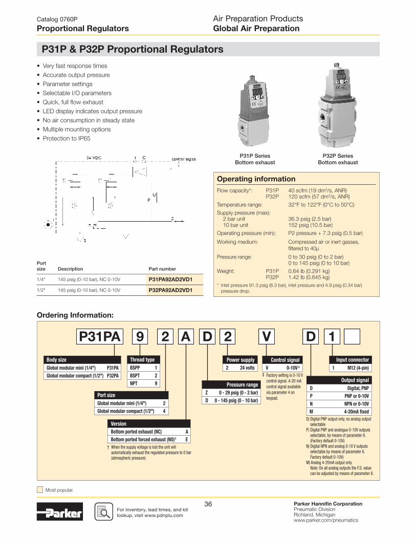
For inventory, lead times, and kit lookup, visit www.pdnplu.com
Parker Hannifi n CorporationPneumatic DivisionRichland, Michiganwww.parker.com/pneumatics
36
P31P SeriesBottom exhaust
P32P SeriesBottom exhaust
• Very fast response times
• Accurate output pressure
• Parameter settings
• Selectable I/O parameters
• Quick, full fl ow exhaust
• LED display indicates output pressure
• No air consumption in steady state
• Multiple mounting options
• Protection to IP65
D) Digital PNP output only, no analog output selectable
P) Digital PNP and analogue 0-10V outputs selectable, by means of parameter 6.(Factory default 0-10V)
N) Digital NPN and analog 0-10 V outputs selectable by means of parameter 6. Factory default 0-10V)
M) Analog 4-20mA output only. Note: On all analog outputs the F.S. value
can be adjusted by means of parameter 8.
† When the supply voltage is lost the unit will automatically exhaust the regulated pressure to 0 bar (atmospheric pressure)
‡ Factory setting is 0-10 V control signal. 4-20 mA control signal available via parameter 4 on keypad.
Version
Bottom ported exhaust (NC) A
Bottom ported forced exhaust (NO) † E
Thread type
BSPP 1
BSPT 2
NPT 9
Port size
Global modular mini (1/4") 2
Global modular compact (1/2") 4
Pressure range
Z 0 - 29 psig (0 - 2 bar)
D 0 - 145 psig (0 - 10 bar)
Power supply
2 24 volts
Control signal
V 0-10V ‡
Input connector
1 M12 (4-pin)
Output signal
D Digital, PNP
P PNP or 0-10V
N NPN or 0-10V
M 4-20mA fi xed
Body size
Global modular mini (1/4") P31PA
Global modular compact (1/2") P32PA
P31PA 9 2 A D 2 V D 1
Port size Description Part number
1/4" 145 psig (0-10 bar), NC 0-10V P31PA92AD2VD1
1/2" 145 psig (0-10 bar), NC 0-10V P32PA92AD2VD1
Catalog 0760P
Proportional Regulators
P31P & P32P Proportional Regulators
Air Preparation ProductsGlobal Air Preparation
Ordering Information:
Operating information
Flow capacity*: P31P 40 scfm (19 dm3/s, ANR)
P32P 120 scfm (57 dm3/s, ANR)
Temperature range: 32°F to 122°F (0°C to 50°C)
Supply pressure (max):
2 bar unit 36.3 psig (2.5 bar)
10 bar unit 152 psig (10.5 bar)
Operating pressure (min): P2 pressure + 7.3 psig (0.5 bar)
Working medium: Compressed air or inert gasses,
fi ltered to 40µ
Pressure range: 0 to 30 psig (0 to 2 bar)
0 to 145 psig (0 to 10 bar)
Weight: P31P 0.64 lb (0.291 kg)
P32P 1.42 lb (0.645 kg)
* Inlet pressure 91.3 psig (6.3 bar), inlet pressure and 4.9 psig (0.34 bar)
pressure drop.
Most popular.

For inventory, lead time, and kit lookup, visit www.pdnplu.com
Parker Hannifi n CorporationPneumatic DivisionRichland, Michiganwww.parker.com/pneumatics
37
Technical Information
Accuracy
+/- 1.0% of F.S.*
* Full scale (F.S.) - For 2 bar (29 psig) versions this will be 2 bar (29 psig),
for the 10 bar (145 psig) version full scale will be 10 bar (145 psig).
Air consumption
No consumption in stable regulated situation.
Display
The regulator is provided with a digital display, indicating the
output pressure, either in bar or psig.
The factory setting is as indicated on the label, can be
changed through to software at all times (parameter 14)
Supply voltage
24 VDC +/- 10%
Power consumption
Max. 1.1W with unloaded signal outputs
Control signals
The electronic pressure regulator can be externally controlled
through an analogue control signal of either 0-10V or 4-20mA.
(parameter 4).
Output signals
As soon as the output pressure is within the signal band a
signal is given of 24VDC, PNP Ri = 1 kOhm
Outside the signal band this connection is 0V.
Connections
(In case of output signal (Option D)
Central M12 connector 4-pole
The electrical connections are as follows:
Pin No. Function Color
1 24 V Supply Brown
20 to 10 V Control Signal Ri = 100k
White4 to 20mA Control Signal Ri = 500
3 0 V (GND) Supply Blue
4 24 V Alarm Output Signal Black
Flow Charts
P32P Regulator 1/2" Ports
P31P Regulator 1/4" Ports
Inlet Pressure - 10 bar (145 psig)
Sec
onda
ry P
ress
ure
- (b
ar)
Sec
onda
ry P
ress
ure
- (p
sig)
0
20
40
60
80
100
120
140
0
2
3
4
5
6
7
8
9
10
1
0
0 60 7010 504020 80 9030 100
Flow - (scfm)20 6040 80 100 120 140 180160 200
Flow - (dm3/s) n
Degree of protection: IP65
EU conformity
CE: standard
EMC: according to directive 89/336/EEC
This pressure regulator is in accordance with:
EN 61000-6-1:2001 EN 61000-6-2:2001 EN 61000-6-3:2001 EN 61000-6-4:2001
Mounting position
Preferably vertical, with the cable gland on top.
Materials: P31P & P32P
Magnet core Steel
Solenoid valve poppet FPM
Solenoid valve housing Techno polymer
Regulator body (P31P & P32P versions) Aluminum
Regulator top housing Nylon
Valve head Brass & NBR
Remaining seals NBR
Catalog 0760P
Proportional Regulators
Air Preparation ProductsGlobal Air Preparation
Inlet Pressure - 10 bar (145 psig)
Sec
onda
ry P
ress
ure
- (b
ar)
Sec
onda
ry P
ress
ure
- (p
sig)
0
20
40
60
80
100
120
140
0
2
3
4
5
6
7
8
9
10
1
0
50 10 15 20 25 30 35
Flow - (scfm)10 20 30 40 50 60 70
Flow - (dm3/s) n

For inventory, lead times, and kit lookup, visit www.pdnplu.com
Parker Hannifi n CorporationPneumatic DivisionRichland, Michiganwww.parker.com/pneumatics
38
Catalog 0760P
Proportional Regulators
Air Preparation ProductsGlobal Air Preparation
How to Videos at www.parker.com/pneu/propreg
Parameter Number 4 – Set Control Signal in Volts or Milliamps
Step 1 2 3 4 5
Press
3-6 seconds
Until Display Reads
Flashing Decimal Flashing Decimal Flashing
Description Accesses changeableparameters.
Accesses parameter no. 4.
Displays current parameter value.
1 = V0 = mA Edits parameter.
Accepts and saves new parameter
setting.Sequences to
next parameter.
Parameter Number 0 – Reset Back to Factory Settings
Step 1 2 3 4 5
Press
3-6 seconds
Until Display Reads
Flashing Decimal Flashing Decimal Flashing
DescriptionAccesses
changeable parameters.
Accesses parameter no. 0.
Displays current parameter value.
Edits parameter.3 = standard
factory settings.If other than 3,
use Up or DownArrow andaccept 3
Accepts and saves new parameter
setting.Sequences to
next parameter.
Pressing the Accept key “acc” for more than 3 seconds, will
activate parameter change mode. The user can then select the
parameters by pressing up or down key (display will show Pxx).
When parameter number is correct, pressing accept again will
enter parameter number (display will show parameter value).
Pressing the up or down key will change the parameter itself
(display will fl ash indicating parameter editing mode). Pressing
the accept key will accept the new parameter value (all digits
will fl ash whilst being accepted).
After releasing all keys, the next parameter number will be
presented on the display (you may step to the next parameter).
When no key is pressed, after 3 seconds the display will show
the actual output pressure.
How to change parameters – How to Videos available at www.parker.com/pneu/propreg
When the unit is initially powered up allow approximately
10 seconds for the unit to “boot-up” before changing
parameter settings.
Only parameter numbers 0, 4, 6, 8, 9, 14, 18, 19, 20, 12, 13
and 21 are accessible to edit. All other parameters are fi xed.
Manual mode:
When keys DOWN and UP are pressed during startup,
(connecting to the 24V power supply) manual mode is
activated. This means that the user is able to in/decrease the
output pressure of the regulator, by pressing the UP or DOWN
key. During this action the display will blink, indicating that the
manual mode is activated. After powering up again, the unit will
revert back to normal mode.
Back to Factory Setting
After start up. (Power is on)
Entering this value in parameter 0 will store the calibrated factory data into the working parameters.
(Default calibration data is used)
or or
or or
Set Control Signal
The unit is factory set for 0-10 V control signal. If 4-20 mA control signal is required, change parameter 4.

For inventory, lead time, and kit lookup, visit www.pdnplu.com
Parker Hannifi n CorporationPneumatic DivisionRichland, Michiganwww.parker.com/pneumatics
39
Catalog 0760P
Proportional Regulators
Air Preparation ProductsGlobal Air Preparation
How to Videos at www.parker.com/pneu/propreg
Parameter Number 6 – Set Output Signal Step 1 2 3 4 5
Press
3-6 seconds
Until Display Reads
Flashing DecimalFlashing Decimal(Value 0, 1 or 2) Flashing
DescriptionAccesses
changeableparameters.
Accesses parameter no. 6.
Displays current parameter value.
1 = m factorydefault for P3H
with analog options
Edits parameter.0 = digital
(NPN or PNP)1 = analog 0..10V
2 = analog 4..20 mA
Accepts and saves new parameter
setting.Sequences to
next parameter.
Parameter Number 8 – Adjust Span Analog Output Signal
Step 1 2 3 4 5
Press
3-6 seconds
Until Display Reads
Flashing Decimal (For 2 bar versions
value = 92)
Flashing Decimal(Value between
0 and 130) Flashing
DescriptionAccesses
changeableparameters.
Accesses parameter no. 8.
Displays current parameter value. Edits parameter.
Accepts and saves new parameter
setting and implements the
new analog signal span.
Sequences to next parameter.
or or
Adjust Span Analog Output Signal
Set value is a % of Full Analog range. As an example for a 0-10V output signal, the original factory setting of 100% will give you
an adjustment of 0-10V. If you reset Parameter 8 to 50%, the new output range would be 0-5V or 50% of the full range.
In the event that the output signal is to low, in a certain application, you can adjust it by increasing Parameter 8 to a maximum
value of 130% of scale.
Note that all values are nominal and that an actual measurement may be required to ensure signal strength.
Set Output Signal
Parameter 6 is used to set the type of output signal to your PLC.
This parameter is used as follows:
Output Signal option “0” = Digital Output – PNP • Factory set at “0” Non Adjustable
Output Signal option “P” = Digital PNP or Analog 1-10V • Factory set at “1” for Analog Signal
• Convert to Digital PNP by changing parameter
to “0” setting
or or
Output Signal option “N” = Digital NPN or Analog 1-10V • Factory set at “1” Analog Signal
• Convert to Digital NPN by changing parameter to “0”
Output Signal option “M” = Analog 4-20 mA • Factory set at “2” Non Adjustable

For inventory, lead times, and kit lookup, visit www.pdnplu.com
Parker Hannifi n CorporationPneumatic DivisionRichland, Michiganwww.parker.com/pneumatics
40
Catalog 0760P
Proportional Regulators
Air Preparation ProductsGlobal Air Preparation
How to Videos at www.parker.com/pneu/propreg
Parameter Number 14 – Set Pressure Scale in psig or bar
Step 1 2 3 4 5
Press
3-6 seconds
Until Display Reads
Flashing Decimal Flashing Decimal Flashing
Description Accesses changeableparameters.
Accesses parameter no. 14.
Displays current parameter value.
1 = psig0 = bar
2 = MPa Edits parameter.
Accepts and saves new parameter
setting.Sequences to
next parameter.
Parameter Number 9 – Adjust Digital Display Value (Pressure Calibration)
Step 1 2 3 4 5
Press
3-6 seconds
Until Display Reads
Flashing Decimal Flashing Decimal Flashing
DescriptionAccesses
changeableparameters.
Accesses parameter no. 9.
Displays current digital display
Use up or down arrows and
accept to adjust the display
value if using an external pressure
sensor.
Accepts and saves new parameter
setting.Sequences to
next parameter.
Adjust Digital Display
If necessary, adjustments can be made to the digital display when using an external pressure sensor.
or or
Set Pressure Scale
Units with NPT port threads are supplied with a factory set psig pressure scale. Use parameter 14 to change scale to bar.
or or
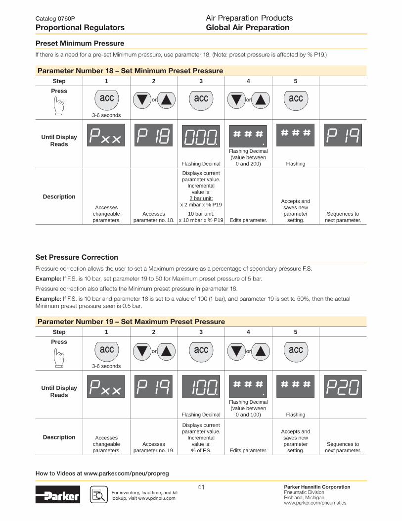
For inventory, lead time, and kit lookup, visit www.pdnplu.com
Parker Hannifi n CorporationPneumatic DivisionRichland, Michiganwww.parker.com/pneumatics
41
Catalog 0760P
Proportional Regulators
Air Preparation ProductsGlobal Air Preparation
How to Videos at www.parker.com/pneu/propreg
Parameter Number 18 – Set Minimum Preset Pressure
Step 1 2 3 4 5
Press
3-6 seconds
Until Display Reads
Flashing Decimal
Flashing Decimal (value between
0 and 200) Flashing
Description
Accesses changeableparameters.
Accesses parameter no. 18.
Displays current parameter value.
Incrementalvalue is:
2 bar unit:x 2 mbar x % P19
10 bar unit:x 10 mbar x % P19 Edits parameter.
Accepts and saves new parameter
setting.Sequences to
next parameter.
Set Pressure Correction
Pressure correction allows the user to set a Maximum pressure as a percentage of secondary pressure F.S.
Example: If F.S. is 10 bar, set parameter 19 to 50 for Maximum preset pressure of 5 bar.
Pressure correction also affects the Minimum preset pressure in parameter 18.
Example: If F.S. is 10 bar and parameter 18 is set to a value of 100 (1 bar), and parameter 19 is set to 50%, then the actual
Minimum preset pressure seen is 0.5 bar.
Preset Minimum Pressure
If there is a need for a pre-set Minimum pressure, use parameter 18. (Note: preset pressure is affected by % P19.)
Parameter Number 19 – Set Maximum Preset Pressure
Step 1 2 3 4 5
Press
3-6 seconds
Until Display Reads
Flashing Decimal
Flashing Decimal (value between
0 and 100) Flashing
Description Accesses changeableparameters.
Accesses parameter no. 19.
Displays current parameter value.
Incrementalvalue is:% of F.S. Edits parameter.
Accepts and saves new parameter
setting.Sequences to
next parameter.
or or
or or

For inventory, lead times, and kit lookup, visit www.pdnplu.com
Parker Hannifi n CorporationPneumatic DivisionRichland, Michiganwww.parker.com/pneumatics
42
Parameter Number 20 – Set Behavior Control Step 1 2 3 4 5
Press
3-6 seconds
Until Display Reads
Flashing Decimal
Flashing Decimal (value between
0 and 5) Flashing
Description
Accesses changeableparameters.
Accesses parameter no. 20.
Displays current parameter value.
Edits parameter0 = custom set*
1 = fastest (narrowproportional band)
2 = fast3 = normal4 = slow
5 = slowest(proportional
band is broad)
Accepts and saves new parameter
setting.Sequences to
next parameter.
Behavior Control
The regulation speed of the pressure regulator can be modifi ed by means of one parameter. (P 20)
The value in this parameter has a range from 0-5. A higher value indicates slower regulation speed, but will be more stable.
* When the value 0 is entered, you are able to create your own custom settings true parameters 12, 13 and 21.
or or
Catalog 0760P
Proportional Regulators
Air Preparation ProductsGlobal Air Preparation
Parameter Number 12 – Set Proportional Band (P20 Must be Set to 0) Step 1 2 3 4 5
Press
3-6 seconds
Until Display Reads
Flashing Decimal
Flashing Decimal (value between
50 and 250) Flashing
Description Accesses changeableparameters.
Accesses parameter no. 12.
Displays current parameter value.
Incrementalvalue is:
x 10 mbar Edits parameter.
Accepts and saves new parameter
setting.Sequences to
next parameter.
Set Proportional Band
Proportional band is used for setting the reaction sensitivity of the regulator. The displayed value is X 10 mbar and has a range
between 50 (0.5 bar) and 250 (2.5 bar).
Fine Settings
or or
How to Videos at www.parker.com/pneu/propreg
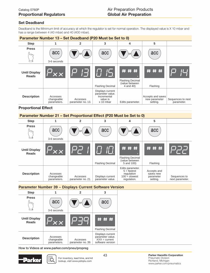
For inventory, lead time, and kit lookup, visit www.pdnplu.com
Parker Hannifi n CorporationPneumatic DivisionRichland, Michiganwww.parker.com/pneumatics
43
Catalog 0760P
Proportional Regulators
Air Preparation ProductsGlobal Air Preparation
Parameter Number 13 – Set Deadband (P20 Must be Set to 0)
Step 1 2 3 4 5
Press
3-6 seconds
Until Display Reads
Flashing Decimal
Flashing Decimal (value between
4 and 40) Flashing
Description Accesses changeableparameters.
Accesses parameter no. 13.
Displays current parameter value.
Incrementalvalue is
x 10 mbar Edits parameter.
Accepts and saves new parameter
setting.Sequences to next
parameter.
Parameter Number 21 – Set Proportional Effect (P20 Must be Set to 0)
Step 1 2 3 4 5
Press
3-6 seconds
Until Display Reads
Flashing Decimal
Flashing Decimal (value between
5 and 100) Flashing
Description Accesses changeableparameters.
Accesses parameter no. 21.
Displays current parameter value.
Edits parameter.5 = fastestregulation
100 = slowestregulation.
Accepts and saves new parameter
setting.Sequences to
next parameter.
Parameter Number 39 – Displays Current Software Version Step 1 2 3
Press
3-6 seconds
Until Display Reads
Flashing Decimal
Description Accesses changeableparameters.
Accesses parameter no. 39.
Displays current parameter value.XXX = current
software version
or
Proportional Effect
or or
Set Deadband
Deadband is the Minimum limit of accuracy at which the regulator is set for normal operation. The displayed value is X 10 mbar and
has a range between 4 (40 mbar) and 40 (400 mbar).
or or
How to Videos at www.parker.com/pneu/propreg

For inventory, lead times, and kit lookup, visit www.pdnplu.com
Parker Hannifi n CorporationPneumatic DivisionRichland, Michiganwww.parker.com/pneumatics
44
P31P
L-Bracket
0.28(7)
0.28(7)
0.28(7)
1.18(30)
1.18(30)
1.42(36)
0.59(15)
0.98(25)
Ø 0.28 (7)4 holes
Foot Bracket
0.39(10)
0.47(12)
2.20(56)
1.02(26)
2.05(52)
3.31(84)
3.94(100)
1.57(40)2.05
(52)
0.79(20)
0.56(14.3)
4 pin M12Connector
0.79(20)
4.99(126.25)
2.25(57)
1.12(28.5)
1.47(37.25)
3.51(89)
1.58(40)
Dimensions inches (mm)
Cables
Description Part number
2 mtr. cable with moulded straight M12x1 connector CB-M12-4P-2M
P3HKA00ML P3HKA00MC
Catalog 0760P
Dimensional Data
Air Preparation ProductsGlobal Air Preparation
Most popular.

For inventory, lead time, and kit lookup, visit www.pdnplu.com
Parker Hannifi n CorporationPneumatic DivisionRichland, Michiganwww.parker.com/pneumatics
45
Dimensions inches (mm)
Cables
Description Part number
2 mtr. cable with moulded straight M12x1 connector CB-M12-4P-2M
P3KKA00ML P3KKA00MC
Catalog 0760P
Dimensional Data
Air Preparation ProductsGlobal Air Preparation
Most popular.
P32P
L-Bracket Foot Bracket
1.77(45)
1.42(36)
1.18(30)
0.59(15)
0.59(15)
0.59(15)
0.98(25)
3.31(84)
Ø 0.28 (7)4 holes
0.47(12)
3.94(100)
2.20(56)
1.02(26)
2.05(52)
1.57(40)
2.05(52)
1.13(28.6)
1.13(28.6)
6.94(175.7)
2.96(75)
1.48(37.5)
2.54(64.4)
4.16(105.3)
2.26(57.2)
0.56(14.3)
4 pin M12Connector

For inventory, lead times, and kit lookup, visit www.pdnplu.com
Parker Hannifi n CorporationPneumatic DivisionRichland, Michiganwww.parker.com/pneumatics
46
• Integral 1/4" ports (NPT, BSPP & BSPT)
• High effi ciency 5 micron element as standard
• Excellent water removal effi ciency
• Robust but lightweight aluminum construction
• Positive bayonet latch to ensure correct & safe fi tting
• Secondary pressure ranges
• Secondary aspiration plus balanced poppet provides quick
response and accurate pressure regulation
Port size
Description(relieving)
Bowl / drain type ‡ Part number
1/4" 125 psig (8 bar) Poly / manual P31EB92EGMBN5P
1/4" 125 psig (8 bar) Poly / pulse P31EB92EGBBN5P
1/4" 125 psig (8 bar) Metal / manual P31EB92EMMBN5P
1/4" 125 psig (8 bar) Metal / pulse P31EB92EMBBN5P
Thread type
BSPP 1
BSPT 2
NPT 9
Mounting
PPlastic panel
mount nutRelief
B Relieving
N Non-relieving
Element
5µ Element E
Bowl type
Poly bowl with bowl guard G
Metal bowl without sight gauge M
Basic series
Global modular mini
fi lter / regulatorP31EB
P31EB 9 2 E G M B N 5 P
Port size
1/4 2
Adjustment
N Non-rising knob
Adjustment range
With square gauge With round gauge
psig bar Z 30 psig; 2 bar; 0.2 MPa
1 = 30* V = 2* M 60 psig; 4 bar; 0.4 MPa
3 = 60 S = 4 G 125 psig; 8 bar; 0.8 MPa
5 = 125 T = 8 J § 232 psig; 16 bar; 1.6 MPa
Without gauge
Y 30 psig; 2 bar; 0.2 MPa
L 60 psig; 4 bar; 0.4 MPa
N 125 psig; 8 bar; 0.8 MPa
H § 232 psig; 16 bar; 1.6 MPa
* Regulator comes with gauge respective to the adjustment range selected.
§ Not available with poly bowl with bowl guard.
Drain type
Pulse drain B
Manual drain M
Flex drain X
Ordering Information:
Air Preparation ProductsGlobal Air Preparation
Catalog 0760P
Mini Filter / Regulators
P31 Filter / Regulators – Mini
Operating information
Flow capacity*: 1/4 73 scfm (35 dm3/s, ANR)
Operating temperature‡: Plastic bowl 14°F to 125°F (-10°C to 52°C)
Metal bowl 14°F to 150°F (-10°C to 65.5°C)
Supply pressure (max):
Plastic bowl 150 psig (10 bar)
Metal bowl 250 psig (17 bar)
Standard fi ltration 5 micron
Useful retention†: 0.4 US oz. (12 cm3)
Adjusting range pressure: 0 to 30 psig (0 to 2 bar)
0 to 60 psig (0 to 4 bar)
0 to 125 psig (0 to 8 bar)
0 to 250 psig (0 to 17 bar)
Gauge port (2 each)**: 1/8 NPT, BSPP, BSPT
Weight: 0.42 lb (0.19 kg)
* Inlet pressure 145 psig (10 bar). Secondary pressure 91.3 psig (6.3 bar)
and 14.5 psig (1 bar) pressure drop.
** Non-gauge option only.‡ Units with square gauges: 5°F to 150°F (-15°C to 65.5°C)† Useful retention refers to volume below the quiet zone baffl e.
21
Air quality: Within ISO 8573-1: 1991 Class 3 (Particulates) Within ISO 8573-1: 2001 Class 6 (Particulates)
‡ For polycarbonate bowl, see caution in Engineering Section A.
Most popular.

For inventory, lead time, and kit lookup, visit www.pdnplu.com
Parker Hannifi n CorporationPneumatic DivisionRichland, Michiganwww.parker.com/pneumatics
47
Flow Charts
Repair and Service Kits
Plastic bowl / bowl guard manual drain P31KB00BGM
Plastic bowl / bowl guard pulse drain P31KB00BGB
Metal bowl / w/o sight gauge pulse drain P31KB00BMB
5µ particle fi lter element P31KA00ESE
Diaphagm repair kit - relieving P31KB00RB
Diaphagm repair kit - non-relieving P31KB00RC
Panel mount nut - aluminum P31KA00MM
Panel mount nut - plastic P31KA00MP
Angle bracket (attaches via panel nut) P31KB00MR
C-bracket (fi ts to body) P31KA00MW
T-bracket with body connector P31KA00MT
Body connector P31KA00CB
Material Specifi cations
Body Aluminum
Adjustment knob Acetal
Body cap ABS
Bonnet PBT
Plastic bowl Polycarbonate
Metal bowl Aluminum
Bowl guard Nylon
Filter element Polyethylene
Seals Nitrile
Springs Steel
Valve assembly Brass / Nitrile
Diaphragm assembly Brass / Nitrile
Panel nut Acetal
P31EB 1/4" Filter / Regulator
Manual Drain Pulse Drain
Inlet Pressure - 10 bar (145 psig)
Sec
onda
ry P
ress
ure
- (b
ar)
Sec
onda
ry P
ress
ure
- (p
sig)
0
20
40
60
80
100
120
140
2.5 bar
36.3 psig
8.0 bar
116 psig
4.0 bar
58 psig
6.3 bar
91.4 psig
0
2
3
4
5
6
7
8
9
10
1
0
0
105 15 25 3520 4030
Flow - (scfm)20 4010 30 60 8050 70
Flow - (dm3/s) n
Air Preparation ProductsGlobal Air Preparation
Catalog 0760P
Mini Filter / Regulators
Gauges
Square fl ush mount gauge
0-4 bar K4511SCR04B
0-11 bar K4511SCR11B
0-60 psig K4511SCR060
0-160 psig K4511SCR160
For best performance, regulated pressure should always be set by increasing the
pressure up to the desired setting.2.89(73.5)
6.96(176.9)
6.77(172)
1.58(40)
1.58(40)
0.79(20)
1.30(33)
Bowlremovalclearance
2.41(61.3)
SquareGauge
2.93(74.3)
RoundGauge
5/32 (4mm)I.D. tubebarb fitting
Inches (mm)
CAUTION:REGULATOR PRESSURE ADJUSTMENT – The working range of knob adjustment is designed to permit outlet pressures within their full range. Pressure adjustment beyond this range is also possible because the knob is not a limiting device. This is a common characteristic of most industrial regulators, and limiting devices may be obtained only by special design. For best performance, regulated pressure should always be set by increasing the pressure up to the desired setting.
WARNING
Product rupture can cause serious injury.Do not connect regulator to bottled gas.
Do not exceed Maximum primary pressure rating.
!

For inventory, lead times, and kit lookup, visit www.pdnplu.com
Parker Hannifi n CorporationPneumatic DivisionRichland, Michiganwww.parker.com/pneumatics
48
Port size
Description (relieving)
Bowl / drain type ‡ Part number
1/4" 125 psig (8 bar) Poly / manual P32EB92EGMBNGP
1/4" 125 psig (8 bar) Poly / auto P32EB92EGABNGP
1/4" 125 psig (8 bar) Metal / manual P32EB92ESMBNGP
1/4" 125 psig (8 bar) Metal / auto P32EB92ESABNGP
3/8" 125 psig (8 bar) Poly / manual P32EB93EGMBNGP
3/8" 125 psig (8 bar) Poly / auto P32EB93EGABNGP
3/8" 125 psig (8 bar) Metal / manual P32EB93ESMBNGP
3/8" 125 psig (8 bar) Metal / auto P32EB93ESABNGP
1/2" 125 psig (8 bar) Poly / manual P32EB94EGMBNGP
1/2" 125 psig (8 bar) Poly / auto P32EB94EGABNGP
1/2" 125 psig (8 bar) Metal / manual P32EB94ESMBNGP
1/2" 125 psig (8 bar) Metal / auto P32EB94ESABNGP
• Integral 1/4", 3/8" or 1/2" ports (NPT, BSPP & BSPT)
• High effi ciency 5 micron element as standard
• Excellent water removal effi ciency
• Robust but lightweight aluminum construction
• Positive bayonet latch to ensure correct & safe fi tting
• Secondary pressure ranges
• Secondary aspiration plus balanced poppet provides quick
response and accurate pressure regulation
21
Drain type
Manual drain M
Auto drain A
Flex drain X
Mounting
PPlastic panel
mount nut
Relief
B Relieving
N Non-relieving
Element
5µ Element E
Bowl type
Poly bowl with bowl guard G
Metal bowl without sight gauge M
Metal bowl with sight gauge S
Basic series
Global modular compact
fi lter / regulatorP32EB
P32EB 9 2 E G M B N 5 P
Port size
1/4 2
3/8 3
1/2 4Adjustment range
With square gauge With round gauge
psig bar Z 30 psig; 2 bar; 0.2 MPa
1 = 30* V = 2* M 60 psig; 4 bar; 0.4 MPa
3 = 60 S = 4 G 125 psig; 8 bar; 0.8 MPa
5 = 125 T = 8 J § 250 psig; 17 bar; 1.7 MPa
Without gauge
Y 30 psig; 2 bar; 0.2 MPa
L 60 psig; 4 bar; 0.4 MPa
N 125 psig; 8 bar; 0.8 MPa
H § 250 psig; 17 bar; 1.7 MPa
* Regulator comes with gauge respective to the adjustment range selected.
§ Not available with poly bowl with bowl guard.
Adjustment
N Non-rising knob
T T-Handle
Thread type
BSPP 1
BSPT 2
NPT 9
Ordering Information:
Catalog 0760P
Compact Filter / Regulators
P32 Filter / Regulators – Compact
Operating information
Flow capacity*: 1/4 148 scfm (70 dm3/s, ANR) 3/8 158 scfm (75 dm3/s, ANR) 1/2 164 scfm (77 dm3/s, ANR)Operating temperature: Plastic bowl -13°F to 125°F (-25°C to 52°C) Metal bowl -13°F to 150°F (-25°C to 65.5°C)
Supply pressure (max): Plastic bowl 150 psig (10 bar) Metal bowl 250 psig (17 bar)
Standard fi ltration: 5 micron
Useful retention†: 1.7 US oz. (51 cm3)
Adjusting range pressure: 0 to 30 psig (0 to 2 bar) 0 to 60 psig (0 to 4 bar) 0 to 125 psig (0 to 8 bar) 0 to 250 psig (0 to 17 bar)
Gauge port (2 each): 1/4 NPT, BSPP, BSPT
Weight: 1.17 lb (0.53 kg)
* Inlet pressure 145 psig (10 bar). Secondary pressure 91.3 psig (6.3 bar)
and 14.5 psig (1 bar) pressure drop. † Useful retention refers to volume below the quiet zone baffl e.
Air quality: Within ISO 8573-1: 1991 Class 3 (Particulates) Within ISO 8573-1: 2001 Class 6 (Particulates)
Air Preparation ProductsGlobal Air Preparation
‡ For polycarbonate bowl, see caution in Engineering Section A.
Most popular.

For inventory, lead time, and kit lookup, visit www.pdnplu.com
Parker Hannifi n CorporationPneumatic DivisionRichland, Michiganwww.parker.com/pneumatics
49
Flow ChartsMaterial Specifi cations
Body Aluminum
Adjustment knob Acetal
Element retainer / baffl e Acetal
Plastic bowl Polycarbonate
Metal bowl Aluminum
Bowl guard Nylon
Filter element Sintered polyethylene
Seals Nitrile
Springs Steel, stainless steel
Valve assembly Brass / nitrile
Diaphragm assembly Nitrile / zinc
Panel nut Acetal
Sight gauge Nylon
Repair and Service Kits
Plastic bowl / bowl guard manual drain P32KB00BGM
Metal bowl / sight gauge manual drain P32KB00BSM
Auto drain P32KA00DA
5µ particle fi lter element P32KA00ESE
Diaphagm repair kit - relieving P32KB00RB
Diaphagm repair kit - non-relieving P32KB00RC
Panel mount nut - aluminum P32KA00MM
Panel mount nut - plastic P32KA00MP
Angle bracket (fi ts to panel mount threads) P32KB00MR
T-bracket (fi ts to body connector) P32KA00MB
T-bracket with body connector P32KA00MT
Body connector P32KA00CB
P32EB 1/4" Filter / Regulator
P32EB3/8" Filter/Regulator
P32EB 1/2" Filter/Regulator
Manual Drain Automatic Drain
Inlet Pressure - 10 bar (145 psig)
Sec
onda
ry P
ress
ure
- (b
ar)
Sec
onda
ry P
ress
ure
- (p
sig)
0
20
40
60
80
100
120
140
2.5 bar36.3 psig
8.0 bar116 psig
4.0 bar58 psig
6.3 bar91.4 psig
0
2
3
4
5
6
7
8
9
10
1
0
0
10 3020 40 50 70 8060
Flow - (SCFM)20 40 60 80 100 120 140 160
Flow - (dm3/s) n
Inlet Pressure - 10 bar (145 psig)
Sec
onda
ry P
ress
ure
- (b
ar)
Sec
onda
ry P
ress
ure
- (p
sig)
0
20
40
60
80
100
120
140
2.5 bar36.3 psig
8.0 bar116 psig
4.0 bar58 psig
6.3 bar91.4 psig
0
2
3
4
5
6
7
8
9
10
1
0
0
2010 4030 60 8050 9070
Flow - (scfm)40 8020 60 120 180160100 140
Flow - (dm3/s) n
Inlet Pressure - 10 bar (145 psig)
Sec
onda
ry P
ress
ure
- (b
ar)
Sec
onda
ry P
ress
ure
- (p
sig)
0
20
40
60
80
100
120
140
2.5 bar36.3 psig
8.0 bar116 psig
4.0 bar58 psig
6.3 bar91.4 psig
0
2
3
4
5
6
7
8
9
10
1
0
0
2010 4030 60 8050 9070
Flow - (scfm)40 8020 60 120 180160100 140
Flow - (dm3/s) n
Gauges
50mm (2") round 1/4" center back mount
0-30 psig / 0-2 bar K4520N14030
0-60 psig / 0-4 bar K4520N14060
0-160 psig / 0-11 bar K4520N14160
0-300 psig / 0-20 bar K4520N14300
For best performance, regulated pressure should always be set by increasing the
pressure up to the desired setting.
Catalog 0760P
Compact Filter / Regulators
Air Preparation ProductsGlobal Air Preparation
3.19(81)
SquareGauge
3.66(93)
RoundGauge
2.36(60)
2.36(60)
3.84(97.6)
10.30(261.6)
10.10(255.6)
1.18(30)
2.28(58)
Bowlremovalclearance
5/32 (4mm)I.D. tubebarb fitting
Inches (mm)
CAUTION:REGULATOR PRESSURE ADJUSTMENT – The working range of knob adjustment is designed to permit outlet pressures within their full range. Pressure adjustment beyond this range is also possible because the knob is not a limiting device. This is a common characteristic of most industrial regulators, and limiting devices may be obtained only by special design. For best performance, regulated pressure should always be set by increasing the pressure up to the desired setting.
WARNING
Product rupture can cause serious injury.Do not connect regulator to bottled gas.
Do not exceed Maximum primary pressure rating.
!

For inventory, lead times, and kit lookup, visit www.pdnplu.com
Parker Hannifi n CorporationPneumatic DivisionRichland, Michiganwww.parker.com/pneumatics
50
• Integral 1/4", 3/8" or 1/2" ports (NPT, BSPP & BSPT)
• High effi ciency 5 micron element as standard
• Excellent water removal effi ciency
• Robust but lightweight aluminum construction
• Positive bayonet latch to ensure correct & safe fi tting
• Secondary pressure ranges
• Secondary aspiration plus balanced poppet provides quick
response and accurate pressure regulation
21
Drain type
Manual drain M
Auto drain A
Mounting
PPlastic panel
mount nut
Relief
P Semi-Precision Relieving
T Semi-Precision Non-relieving
Element
5µ Element E
Bowl type
Poly bowl with bowl guard G
Metal bowl without sight gauge M
Metal bowl with sight gauge S
Basic series
Global modular compact
fi lter / regulatorP32EB
P32EB 9 2 E G M P N G P
Port size
1/4 2
3/8 3
1/2 4Adjustment range
With square gauge With round gauge
psig bar Z 30 psig; 2 bar; 0.2 MPa
1 = 30* V = 2* M 60 psig; 4 bar; 0.4 MPa
3 = 60 S = 4 G 125 psig; 8 bar; 0.8 MPa
5 = 125 T = 8 J § 250 psig; 17 bar; 1.7 MPa
Without gauge
Y 30 psig; 2 bar; 0.2 MPa
L 60 psig; 4 bar; 0.4 MPa
N 125 psig; 8 bar; 0.8 MPa
H § 250 psig; 17 bar; 1.7 MPa
* Regulator comes with gauge respective to the adjustment range selected.
§ Not available with poly bowl with bowl guard.
Adjustment
N Non-rising knob
T T-Handle
Thread type
BSPP 1
BSPT 2
NPT 9
Catalog 0760P
Compact Semi-Precision Filter / Regulators
P32 Semi-Precision Filter / Regulators – Compact
Air Preparation ProductsGlobal Air Preparation
Ordering Information:
Operating information
Flow capacity*:
1/4, 3/8, 1/2 35 dm3/s, ANR (75 scfm)
Operating temperature:
Plastic bowl -25°C to 52°C (-13°F to 125°F)
Metal bowl -25°C to 65.5°C (-13°F to 150°F)
Supply pressure (max):
Plastic bowl 10 bar (150 psig)
Metal bowl 17 bar (250 psig)
Standard fi ltration: 5 micron
Useful retention†: 51 cm3 (1.7 US oz.)
Adjusting range pressure: 0-2 bar (30 psig)
0-4 bar (60 psig)
0-8 bar (125 psig)
0-17 bar (250 psig)
Gauge port (2 each): 1/4 BSPP, BSPT, NPT
* Inlet pressure 10 bar (145 psig), secondary pressure 6.3 bar (91.3 psig). † Useful retention refers to volume below the quiet zone baffl e.
Air quality: Within ISO 8573-1: 1991 Class 3 (Particulates) Within ISO 8573-1: 2001 Class 6 (Particulates)
Port size
Description / relieving
Bowl / drain type ‡ Part number
1/4" 125 psig (8 bar) Poly / manual P32EB92EGMPNGP
1/4" 125 psig (8 bar) Poly / auto P32EB92EGAPNGP
1/4" 125 psig (8 bar) Metal / manual P32EB92ESMPNGP
1/4" 125 psig (8 bar) Metal / auto P32EB92ESAPNGP
3/8" 125 psig (8 bar) Poly / manual P32EB93EGMPNGP
3/8" 125 psig (8 bar) Poly / auto P32EB93EGAPNGP
3/8" 125 psig (8 bar) Metal / manual P32EB93ESMPNGP
3/8" 125 psig (8 bar) Metal / auto P32EB93ESAPNGP
1/2" 125 psig (8 bar) Poly / manual P32EB94EGMPNGP
1/2" 125 psig (8 bar) Poly / auto P32EB94EGAPNGP
1/2" 125 psig (8 bar) Metal / manual P32EB94ESMPNGP
1/2" 125 psig (8 bar) Metal / auto P32EB94ESAPNGP
Operating information
Flow capacity*: 1/4, 3/8, 1/2 75 scfm (35 dm3/s, ANR)
Effect of supply 0.6 psig (0.04 bar) for
pressure variation 25 psig (1.7 bar) change in P1
Operating temperature:
Plastic bowl -13°F to 125°F (-25°C to 52°C)
Metal bowl -13°F to 150°F (-25°C to 65.5°C)
Supply pressure (max):
Plastic bowl 150 psig (10 bar)
Metal bowl 250 psig (17 bar)
Standard fi ltration: 5 micron
Useful retention†: 1.7 US oz. (51 cm3)
Adjusting range pressure: 0 to 30 psig (0 to 2 bar)
0 to 60 psig (0 to 4 bar)
0 to 125 psig (0 to 8 bar)
0 to 250 psig (0 to 17 bar)
Gauge port (2 each): 1/4 NPT, BSPP, BSPT
Weight: 0.53 lb (1.17 kg)
* Inlet pressure 145 psig (10 bar). Secondary pressure 91.3 psig (6.3 bar)
and 14.5 psig (1 bar) pressure drop. † Useful retention refers to volume below the quiet zone baffl e.‡ For polycarbonate bowl, see caution in Engineering Section A.
Most popular.

For inventory, lead time, and kit lookup, visit www.pdnplu.com
Parker Hannifi n CorporationPneumatic DivisionRichland, Michiganwww.parker.com/pneumatics
51
Flow ChartsMaterial Specifi cations
Body Aluminum
Adjustment knob Acetal
Element retainer / baffl e Acetal
Plastic bowl Polycarbonate
Metal bowl Aluminum
Bowl guard Nylon
Filter element Sintered polyethylene
Seals Nitrile
Springs Steel, stainless steel
Valve assembly Brass / nitrile
Diaphragm assembly Nitrile / zinc
Panel nut Acetal
Sight gauge Nylon
Repair and Service Kits
Plastic bowl / bowl guard manual drain P32KB00BGM
Metal bowl / sight gauge manual drain P32KB00BSM
Auto drain P32KA00DA
5µ particle fi lter element P32KA00ESE
Diaphagm repair kit - relieving P32KB00RB
Diaphagm repair kit - non-relieving P32KB00RC
Panel mount nut - aluminum P32KA00MM
Panel mount nut - plastic P32KA00MP
Angle bracket (fi ts to panel mount threads) P32KB00MR
T-bracket (fi ts to body connector) P32KA00MB
T-bracket with body connector P32KA00MT
Body connector P32KA00CB
P32EB 1/4" Filter / Regulator
P32EB 3/8" Filter/Regulator
P32EB 1/2" Filter/Regulator
Inlet Pressure - 10 bar (145 psig)
Sec
onda
ry P
ress
ure
- (b
ar)
Sec
onda
ry P
ress
ure
- (p
sig)
0
20
40
60
80
100
120
140
2.5 bar
36.3 psig
8.0 bar
116 psig
4.0 bar
58 psig
6.3 bar
91.4 psig
0
2
3
4
5
6
7
8
9
10
1
0
0
105 15 25 3520 4030
Flow - (scfm)20 4010 30 60 8050 70
Flow - (dm3/s) n
Inlet Pressure - 10 bar (145 psig)
Sec
onda
ry P
ress
ure
- (b
ar)
Sec
onda
ry P
ress
ure
- (p
sig)
0
20
40
60
80
100
120
140
2.5 bar
36.3 psig
8.0 bar
116 psig
4.0 bar
58 psig
6.3 bar
91.4 psig
0
2
3
4
5
6
7
8
9
10
1
0
0
105 15 25 3520 4030
Flow - (scfm)20 4010 30 60 8050 70
Flow - (dm3/s) n
Inlet Pressure - 10 bar (145 psig)
Sec
onda
ry P
ress
ure
- (b
ar)
Sec
onda
ry P
ress
ure
- (p
sig)
0
20
40
60
80
100
120
140
2.5 bar
36.3 psig
8.0 bar
116 psig
4.0 bar
58 psig
6.3 bar
91.4 psig
0
2
3
4
5
6
7
8
9
10
1
0
0
105 15 25 3520 4030
Flow - (scfm)20 4010 30 60 8050 70
Flow - (dm3/s) n
Catalog 0760P
Compact Semi-Precision Filter / Regulators
Air Preparation ProductsGlobal Air Preparation
Gauges
50mm (2") round 1/4" center back mount
0-30 psig / 0-2 bar K4520N14030
0-60 psig / 0-4 bar K4520N14060
0-160 psig / 0-11 bar K4520N14160
0-300 psig / 0-20 bar K4520N14300
For best performance, regulated pressure should always be set by increasing the
pressure up to the desired setting.Manual Drain Automatic Drain
3.19(81)
SquareGauge
3.66(93)
RoundGauge
2.36(60)
2.36(60)
3.84(97.6)
10.30(261.6)
10.10(255.6)
1.18(30)
2.28(58)
Bowlremovalclearance
5/32 (4mm)I.D. tubebarb fitting
Inches (mm)
CAUTION:REGULATOR PRESSURE ADJUSTMENT – The working range of knob adjustment is designed to permit outlet pressures within their full range. Pressure adjustment beyond this range is also possible because the knob is not a limiting device. This is a common characteristic of most industrial regulators, and limiting devices may be obtained only by special design. For best performance, regulated pressure should always be set by increasing the pressure up to the desired setting.
WARNING
Product rupture can cause serious injury.Do not connect regulator to bottled gas.
Do not exceed Maximum primary pressure rating.
!

For inventory, lead times, and kit lookup, visit www.pdnplu.com
Parker Hannifi n CorporationPneumatic DivisionRichland, Michiganwww.parker.com/pneumatics
52
Port size
Description / relieving
Bowl / drain type ‡ Part number
1/2" 125 psig (8 bar) Poly / manual P33EA94EGMBNGP
1/2" 125 psig (8 bar) Poly / auto P33EA94EGABNGP
1/2" 125 psig (8 bar) Metal / manual P33EA94ESMBNGP
1/2" 125 psig (8 bar) Metal / auto P33EA94ESABNGP
3/4" 125 psig (8 bar) Poly / manual P33EA96EGMBNGP
3/4" 125 psig (8 bar) Poly / auto P33EA96EGABNGP
3/4" 125 psig (8 bar) Metal / manual P33EA96ESMBNGP
3/4" 125 psig (8 bar) Metal / auto P33EA96ESABNGP
• Integral 1/2" or 3/4" ports (NPT, BSPP & BSPT)
• High effi ciency 5 micron element as standard
• Excellent water removal effi ciency
• Robust but lightweight aluminum construction
• Positive bayonet latch to ensure correct & safe fi tting
• Secondary pressure ranges
• Secondary aspiration plus balanced poppet provides quick
response and accurate pressure regulation
21
Thread type
BSPP 1
BSPT 2
NPT 9
Mounting
PPlastic panel
mount nut
Relief
B Relieving
N Non-relieving
Element
5µ Element E
Bowl type
Poly bowl with bowl guard G
Metal bowl without sight gauge M
Metal bowl with sight gauge S
Basic series
Global modular standard
fi lter / regulatorP33EA
P33EA 9 6 E G M B N G P
Port size
1/2 4
3/4 6
Drain type
M Manual drain
A Auto drain
Adjustment range
With round gauge
Z 30 psig; 2 bar; 0.2 MPa
M 60 psig; 4 bar; 0.4 MPa
G 125 psig; 8 bar; 0.8 MPa
J§ 250 psig; 17 bar; 1.7 MPa
Without gauge
Y 30 psig; 2 bar; 0.2 MPa
L 60 psig; 4 bar; 0.4 MPa
N 125 psig; 8 bar; 0.8 MPa
H§ 250 psig; 17 bar; 1.7 MPa
§ Not available with poly bowl with bowl guard.
Adjustment
NNon-rising
knob
Catalog 0760P
Standard Filter / Regulators
P33 Filter / Regulators – Standard
Air Preparation ProductsGlobal Air Preparation
Ordering Information:Air quality: Within ISO 8573-1: 1991 Class 3 (Particulates) Within ISO 8573-1: 2001 Class 6 (Particulates)
Operating information
Flow capacity*: 1/2 200 scfm (94 dm3/s, ANR)
3/4 235 scfm (109 dm3/s, ANR)
Operating temperature:
Plastic bowl -13°F to 125°F (-25°C to 52°C)
Metal bowl -13°F to 150°F (-25°C to 65.5°C)
Supply pressure (max):
Plastic bowl 150 psig (10 bar)
Metal bowl 250 psig (17 bar)
Standard fi ltration: 5 micron
Useful retention†: 2.8 US oz. (85 cm3)
Adjusting range pressure: 0 to 30 psig (0 to 2 bar)
0 to 60 psig (0 to 4 bar)
0 to 125 psig (0 to 8 bar)
0 to 250 psig (0 to 17 bar)
Gauge port (2 each): 1/4 NPT, BSPP, BSPT
Weight: 1.87 psig (8 bar)
* Inlet pressure 145 psig (10 bar). Secondary pressure 91.3 psig (6.3 bar)
and 14.5 psig (1 bar) pressure drop. † Useful retention refers to volume below the quiet zone baffl e.
‡ For polycarbonate bowl, see caution in Engineering Section A.
Most popular.
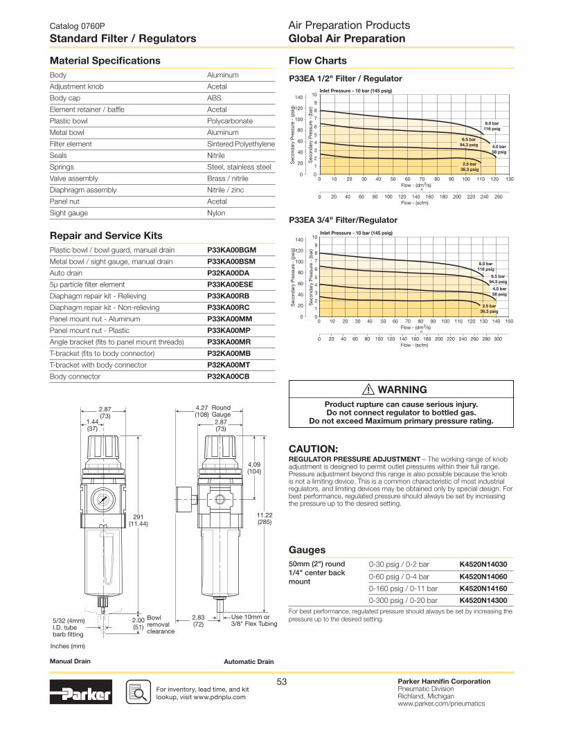
For inventory, lead time, and kit lookup, visit www.pdnplu.com
Parker Hannifi n CorporationPneumatic DivisionRichland, Michiganwww.parker.com/pneumatics
53
Inlet Pressure - 10 bar (145 psig)
Sec
onda
ry P
ress
ure
- (b
ar)
Sec
onda
ry P
ress
ure
- (p
sig)
0
20
40
60
80
100
120
140
2.5 bar
36.3 psig
8.0 bar
116 psig
4.0 bar
58 psig
6.5 bar
94.3 psig
0
2
3
4
5
6
7
8
9
10
1
0
0
10 3020 40 13050 100 11070 12080 9060
Flow - (scfm)20 40 60 80 100 120 140 240 260200 220180160
Flow - (dm3/s) n
Flow ChartsMaterial Specifi cations
Body Aluminum
Adjustment knob Acetal
Body cap ABS
Element retainer / baffl e Acetal
Plastic bowl Polycarbonate
Metal bowl Aluminum
Filter element Sintered Polyethylene
Seals Nitrile
Springs Steel, stainless steel
Valve assembly Brass / nitrile
Diaphragm assembly Nitrile / zinc
Panel nut Acetal
Sight gauge Nylon
Repair and Service Kits
Plastic bowl / bowl guard, manual drain P33KA00BGM
Metal bowl / sight gauge, manual drain P33KA00BSM
Auto drain P32KA00DA
5µ particle fi lter element P33KA00ESE
Diaphagm repair kit - Relieving P33KA00RB
Diaphagm repair kit - Non-relieving P33KA00RC
Panel mount nut - Aluminum P33KA00MM
Panel mount nut - Plastic P33KA00MP
Angle bracket (fi ts to panel mount threads) P33KA00MR
T-bracket (fi ts to body connector) P32KA00MB
T-bracket with body connector P32KA00MT
Body connector P32KA00CB
P33EA 1/2" Filter / Regulator
Inlet Pressure - 10 bar (145 psig)
Sec
onda
ry P
ress
ure
- (b
ar)
Sec
onda
ry P
ress
ure
- (p
sig)
0
20
40
60
80
100
120
140
2.5 bar
36.3 psig
8.0 bar
116 psig
4.0 bar
58 psig
6.5 bar
94.3 psig
0
2
3
4
5
6
7
8
9
10
1
0
0
10 3020 40 150130 14050 100 11070 12080 9060
Flow - (scfm)20 40 60 80 100 120 140 240 260 280 300200 220180160
Flow - (dm3/s) n
P33EA 3/4" Filter/Regulator
Manual Drain Automatic Drain
Catalog 0760P
Standard Filter / Regulators
Air Preparation ProductsGlobal Air Preparation
Gauges
50mm (2") round 1/4" center back mount
0-30 psig / 0-2 bar K4520N14030
0-60 psig / 0-4 bar K4520N14060
0-160 psig / 0-11 bar K4520N14160
0-300 psig / 0-20 bar K4520N14300
For best performance, regulated pressure should always be set by increasing the
pressure up to the desired setting.
2.87(73)
2.87(73)
291(11.44)
2.00(51)
11.22(285)
1.44(37)
2.83(72)
4.09(104)
4.27(108)
RoundGauge
Use 10mm or3/8" Flex Tubing
Bowlremovalclearance
5/32 (4mm)I.D. tubebarb fitting
Inches (mm)
CAUTION:REGULATOR PRESSURE ADJUSTMENT – The working range of knob adjustment is designed to permit outlet pressures within their full range. Pressure adjustment beyond this range is also possible because the knob is not a limiting device. This is a common characteristic of most industrial regulators, and limiting devices may be obtained only by special design. For best performance, regulated pressure should always be set by increasing the pressure up to the desired setting.
WARNING
Product rupture can cause serious injury.Do not connect regulator to bottled gas.
Do not exceed Maximum primary pressure rating.
!

For inventory, lead times, and kit lookup, visit www.pdnplu.com
Parker Hannifi n CorporationPneumatic DivisionRichland, Michiganwww.parker.com/pneumatics
54
1 2
Lubricatorwith drain
• Integral 1/4" ports (NPT, BSPP & BSPT)
• Robust but lightweight aluminum construction
• Proportional oil delivery over a wide range of air fl ows
• Finger tip ratchet control for precise oil drip rate adjustment
Thread type
BSPP 1
BSPT 2
NPT 9
Mounting
N No bracket
Lube type
Oil mist standard sight dome L
Drain type
N No drain closed end
Bowl type
G Poly bowl with bowl guard
M Metal bowl without sight gauge
Basic series
Global modular
mini lubricatorP31LB
P31LB 9 2 L G N N
Port size
1/4 2
Catalog 0760P
Mini Lubricators
P31 Lubricators – Mini
Air Preparation ProductsGlobal Air Preparation
Port size Description ‡ Part number
1/4" Poly bowl - No drain P31LB92LGNN
1/4" Metal bowl - No drain P31LB92LMNN
Operating information
Flow capacity*:
1/4 52 scfm (25 dm3/s, ANR)
Operating temperature:
Plastic bowl 14°F to 125°F (-10°C to 52°C)
Metal bowl 14°F to 150°F (-10°C to 65.5°C)
Supply pressure (max):
Plastic bowl 150 psig (10 bar)
Metal bowl 250 psig (17 bar)
Bowl capacity: 0.6 US oz. (18 cm3)
Weight: 0.29 lb (0.13 kg)
* Inlet pressure 91.3 psig (6.3 bar). Pressure drop 4.9 psig (0.34 bar).
Ordering Information:
Suggested Lubricant .................................................................F442 Oil
Petroleum based oil of 100 to 200 SUS viscosity at 100°F (38°C) and an
aniline point greater than 200°F (93°C)
(DO NOT USE OILS WITH ADDITIVES, COMPOUNDED OILS CONTAINING
SOLVENTS, GRAPHITE, DETERGENTS, OR SYNTHETIC OILS.)
‡ For polycarbonate bowl, see caution in Engineering Section A.
Most popular.

For inventory, lead time, and kit lookup, visit www.pdnplu.com
Parker Hannifi n CorporationPneumatic DivisionRichland, Michiganwww.parker.com/pneumatics
55
Material Specifi cations
Body Aluminum
Body cap ABS
Plastic bowl Polycarbonate
Metal bowl Aluminum
Seals Nitrile
Sight dome Polycarbonate
Suggested lubricant ISO / ASTM VG32
Pick-up fi lter Sintered bronze
Flow Charts
Repair and Service Kits
Plastic bowl / bowl guard no drain P31KB00BGN
Metal bowl / w/o sight gauge no drain P31KB00BMN
Drip control assembly P32KA00PG
Fill plug P31KA00PL
C-bracket (fi ts to body) P31KA00MW
T-bracket with body connector P31KA00MT
Body connector P31KA00CB
Oil (1 quart) F442001
Oil (1 galllon) F442002
Oil (12 quart case) F442003
Oil (4 gallon case) F442005
P31LB 1/4" Lubricator
Pre
ssur
e D
rop
- (b
ar)
Pre
ssur
e D
rop
- (p
sig)
0
2
4
6
5
3
1
7
0
0.1
0.2
0.3
0.4
0.5
2.5
36.2
Primary Pressure - bar
Primary Pressure - psig
6.3
91.4
10
145
0
0
30 40 5010 20
Flow - (scfm)20 40 60 80 100
Flow - (dm3/s) n
Catalog 0760P
Mini Lubricators
Air Preparation ProductsGlobal Air Preparation
1.58(40)
1.58(40)
0.79(20)
2.22(56.3)
6.04(153.3)
1.30(33)
Bowlremovalclearance
Inches (mm)

For inventory, lead times, and kit lookup, visit www.pdnplu.com
Parker Hannifi n CorporationPneumatic DivisionRichland, Michiganwww.parker.com/pneumatics
56
Port size Description ‡ Part number
1/4" Poly bowl - No drain P32LB92LGNN
1/4" Metal bowl - No drain P32LB92LSNN
3/8" Poly bowl - No drain P32LB93LGNN
3/8" Metal bowl - No drain P32LB93LSNN
1/2" Poly bowl - No drain P32LB94LGNN
1/2" Metal bowl - No drain P32LB94LSNN
• Integral 1/4", 3/8" or 1/2" ports (NPT, BSPP & BSPT)
• Robust but lightweight aluminum construction
• Proportional oil delivery over a wide range of air fl ows
• Finger tip ratchet control for precise oil drip rate adjustment
• Fill from top under system pressure
1 2
Lubricatorwith drain
Thread type
BSPP 1
BSPT 2
NPT 9
Mounting
N No bracket
Drain type
N No drain closed end
Bowl type
G Poly bowl with bowl guard
S Metal bowl with sight gauge
Basic series
Global modular
compact lubricatorP32LB
P32LB 9 2 L G N N
Port size
1/4 2
3/8 3
1/2 4
Lube type
Oil mist standard sight dome L
Catalog 0760P
Compact Lubricators
P32 Lubricators – Compact
Air Preparation ProductsGlobal Air Preparation
Operating information
Flow capacity*:
1/4 38 scfm (17 dm3/s, ANR)
3/8 70 scfm (33 dm3/s, ANR)
1/2 90 scfm (42 dm3/s, ANR)
Operating temperature:
Plastic bowl 14°F to 125°F (-10°C to 52°C)
Metal bowl 14°F to 150°F (-10°C to 65.5°C)
Supply pressure (max):
Plastic bowl 150 psig (10 bar)
Metal bowl 250 psig (17 bar)
Bowl capacity: 4.09 US oz. (121 cm3)
Weight: 0.68 lb (0.31 kg)
* Inlet pressure 91.3 psig (6.3 bar). Pressure drop 4.9 psig (0.34 bar).
Ordering Information:
Suggested Lubricant .................................................................F442 Oil
Petroleum based oil of 100 to 200 SUS viscosity at 100°F (38°C) and an
aniline point greater than 200°F (93°C)
(DO NOT USE OILS WITH ADDITIVES, COMPOUNDED OILS CONTAINING
SOLVENTS, GRAPHITE, DETERGENTS, OR SYNTHETIC OILS.)
‡ For polycarbonate bowl, see caution in Engineering Section A.
Most popular.

For inventory, lead time, and kit lookup, visit www.pdnplu.com
Parker Hannifi n CorporationPneumatic DivisionRichland, Michiganwww.parker.com/pneumatics
57
Pre
ssur
e D
rop
- (b
ar)
Pre
ssur
e D
rop
- (p
sig)
0
2
4
6
5
3
1
7
00
0
10 20 30 40 50 60 70 80
Flow - (scfm)20 40 8060 100 120 140 160
0.1
0.2
0.3
0.4
0.5
1.6
23.2
Primary Pressure - bar
Primary Pressure - psig
4.0
58
6.3
91.4
10
145
Flow - (dm3/s) n
Pre
ssur
e D
rop
- (b
ar)
Pre
ssur
e D
rop
- (p
sig)
0
2
4
6
5
3
1
7
00
0
10 20 30
Flow - (scfm)10 20 4030 50 60
0.1
0.2
0.3
0.4
0.5
1.6
23.2
Primary Pressure - bar
Primary Pressure - psig
4.0
58
6.3
91.4
10
145
Flow - (dm3/s) n
Pre
ssur
e D
rop
- (b
ar)
Pre
ssur
e D
rop
- (p
sig)
0
2
4
6
5
3
1
7
00
0
40 50 60 7010 20 30
Flow - (scfm)20 40 10080 120 14060
0.1
0.2
0.3
0.4
0.5
1.6
23.2
Primary Pressure - bar
Primary Pressure - psig
4.0
58
6.3
91.4
10
145
Flow - (dm3/s) n
Flow ChartsMaterial Specifi cations
Body Aluminum
Body cap ABS
Plastic bowl Polycarbonate
Metal bowl Aluminum
Seals Nitrile
Sight dome Polycarbonate
Sight gauge Nylon
Suggested lubricant ISO / ASTM VG32
Pick-up fi lter Sintered bronze
Repair and Service Kits
Plastic bowl / bowl guard no drain P32KB00BGN
Metal bowl / w/o sight gauge no drain P32KB00BMN
Metal bowl / Sight gauge no drain P32KB00BSN
Drip control assembly P32KA00PG
Fill plug P32KA00PL
L-bracket (fi ts to body) P32KA00ML
T-bracket (fi ts to body connector) P32KA00MB
T-bracket with body connector P32KA00MT
Body connector P32KA00CB
Oil (1 quart) F442001
Oil (1 galllon) F442002
Oil (12 quart case) F442003
Oil (4 gallon case) F442005
P32LB 1/4" Lubricator
P32LB 3/8" Lubricator
P32LB 1/2" Lubricator
Catalog 0760P
Compact Lubricators
Air Preparation ProductsGlobal Air Preparation
2.36(60)
2.36(60)
2.45(62.3)
8.56(217.3)
1.18(30)
2.28(58)
Bowlremovalclearance
Inches (mm)

For inventory, lead times, and kit lookup, visit www.pdnplu.com
Parker Hannifi n CorporationPneumatic DivisionRichland, Michiganwww.parker.com/pneumatics
58
Port size Description ‡ Part number
1/2" Poly bowl - No drain P33LA94LGNN
1/2" Metal bowl - No drain P33LA94LSNN
3/4" Poly bowl - No drain P33LA96LGNN
3/4" Metal bowl - No drain P33LA96LSNN
• Integral 1/2" or 3/4" ports (NPT, BSPP & BSPT)
• Robust but lightweight aluminum construction
• Proportional oil delivery over a wide range of air fl ows
• Finger tip ratchet control for precise oil drip rate adjustment
• Fill from top under system pressure
1 2
Lubricatorwith drain
Lube type
Oil mist standard sight dome L
Thread type
BSPP 1
BSPT 2
NPT 9
Mounting
N No bracket
Drain type
N No drain closed end
Bowl type
G Poly bowl with bowl guard
S Metal bowl with sight gauge
Basic series
Global modular
standard lubricatorP33LA
P33LA 9 6 L G N N
Port size
1/2 4
3/4 6
Catalog 0760P
Standard Lubricators
P33 Lubricators – Standard
Air Preparation ProductsGlobal Air Preparation
Operating information
Flow capacity*:
1/2 110 scfm (52 dm3/s, ANR)
3/4 150 scfm (71 dm3/s, ANR)
Operating temperature:
Plastic bowl 14°F to 125°F (-10°C to 52°C)
Metal bowl 14°F to 150°F (-10°C to 65.5°C)
Supply pressure (max):
Plastic bowl 150 psig (10 bar)
Metal bowl 250 psig (17 bar)
Bowl capacity: 6.1 US oz. (181 cm3)
Weight: 1.04 lb (0.47 kg)
* Inlet pressure 91.3 psig (6.3 bar). Pressure drop 4.9 psig (0.34 bar).
Ordering Information:
Suggested Lubricant .................................................................F442 Oil
Petroleum based oil of 100 to 200 SUS viscosity at 100°F (38°C) and an
aniline point greater than 200°F (93°C)
(DO NOT USE OILS WITH ADDITIVES, COMPOUNDED OILS CONTAINING
SOLVENTS, GRAPHITE, DETERGENTS, OR SYNTHETIC OILS.)
‡ For polycarbonate bowl, see caution in Engineering Section A.
Most popular.

For inventory, lead time, and kit lookup, visit www.pdnplu.com
Parker Hannifi n CorporationPneumatic DivisionRichland, Michiganwww.parker.com/pneumatics
59
Pre
ssur
e D
rop
- (b
ar)
Pre
ssur
e D
rop
- (p
sig)
0
2
4
6
5
3
1
7
00
0
10 20 30 40 9050 60 100 11070 12080
Flow - (scfm)20 40 8060 100 120 140 240200 220180160
0.1
0.2
0.3
0.4
0.5
1.6
23.2
Primary Pressure - bar
Primary Pressure - psig
4.0
58
6.3
91.4
10
145
Flow - (dm3/s) n
Pre
ssur
e D
rop
- (b
ar)
Pre
ssur
e D
rop
- (p
sig)
0
2
4
6
5
3
1
7
00
0
10 20 30 40 9050 60 100 11070 12080
Flow - (scfm)20 40 8060 100 120 140 240200 220180160
0.1
0.2
0.3
0.4
0.5
1.6
23.2
Primary Pressure - bar
Primary Pressure - psig
4.0
58
6.3
91.4
Flow - (dm3/s) n
Flow ChartsMaterial Specifi cations
Body Aluminum
Body cap ABS
Plastic bowl Polycarbonate
Metal bowl Aluminum
Seals Nitrile
Sight dome Polycarbonate
Sight gauge Nylon
Suggested lubricant ISO / ASTM VG32
Pick-up fi lter Sintered bronze
Repair and Service Kits
Plastic bowl / bowl guard no drain P33KA00BGN
Metal bowl / w/o sight gauge no drain P33KA00BMN
Metal bowl / sight gauge no drain P33KA00BSN
Drip control assembly P32KA00PG
Fill plug P32KA00PL
L-bracket (fi ts to body) P33KA00ML
T-bracket (fi ts to body connector) P32KA00MB
T-bracket with body connector P32KA00MT
Body connector P32KA00CB
Oil (1 quart) F442001
Oil (1 galllon) F442002
Oil (12 quart case) F442003
Oil (4 gallon case) F442005
P33LA 1/2" Lubricator
P33LA 3/4" Lubricator
Catalog 0760P
Standard Lubricators
Air Preparation ProductsGlobal Air Preparation
2.90(73) 2.90
(73)
2.00(51)
9.20(234)
1.44(36)
2.00(51)
Bowlremovalclearance
Inches (mm)

For inventory, lead times, and kit lookup, visit www.pdnplu.com
Parker Hannifi n CorporationPneumatic DivisionRichland, Michiganwww.parker.com/pneumatics
60For inventory, lead times, and kit lookup, visit www.pdnplu.com
Parker Hannifi n CorporationPneumatic DivisionRichland, Michiganwww.parker.com/pneumatics
60
Air Preparation ProductsGlobal Air Preparation
Catalog 0760P
Mini Combinations
C
Popular Combinations: Inlet pressure 145 psig (10 bar), secondary pressure 91.3 psig (6.3 bar), 14.5 psig (1 bar) pressure drop.
Filter + Regulator + Lubricator Combinations, poly bowl
5 micron element, 116 psig (8 bar) regulator + gauge and wall mounting brackets
Filter/Regulator + Lubricator Combinations, poly bowl
5 micron element, 116 psig (8 bar) regulator + gauge and wall mounting brackets
P31
Element
5µ Element E
0.01µ Element C
1µ Element 9
Adsorber A
Drain type
Manual drain M
Pulse drain B
Lub type
Oil mist
standard
sight dome
L
Drain type
No drain;
closed endN
Mounting
No bracket A
Port blocks C*
Port blocks
& wall brktD*
Wall bracket W
Filter coding(use with combo codes:
B F G). For multiple
fi lters, repeat as needed.
Regulator coding(use with combo code: B)
Lubricator coding(use with combo
codes: A B)
Assembly
confi guration
Filter / Regulator coding
(use with codes: A M)
Port size Flow Manual drain Pulse drain
1/4" 27 scfm (13 dm3/s, ANR) P31CB92GEMN5LNW P31CB92GEBN5LNW
Port size Flow Manual drain Pulse drain
1/4" 28 scfm (14 dm3/s, ANR) P31CA92GEMN5LNW P31CA92GEBN5LNW
Ball Valve + Filter + Regulator + Lubricator Combinations, poly bowl
5 micron element, 116 psig (8 bar) regulator + gauge and wall mounting brackets
Ball Valve + Filter/Regulator + Lubricator Combinations, poly bowl
5 micron element, 116 psig (8 bar) regulator + gauge and wall mounting brackets
Port size Flow Manual drain Pulse drain
1/4" 27 scfm (13 dm3/s, ANR) P31QB92GEMN5LNW P31QB92GEBN5LNW
Port size Flow Manual drain Pulse drain
1/4" 28 scfm (14 dm3/s, ANR) P31QA92GEMN5LNW P31QA92GEBN5LNW
* For 3/8” Port
Blocks please
order separately.
See Kits section.
Note: All bowl types are the same
for each component
Example: If a “G” is specifi ed for a
F+L, both units would get a poly bowl
with bowl guard.
Combination
B/V + Combination Q
Combination + B/V X
Combination C
B/V = Ball valve
Bowl type
Poly bowl with bowl guard ‡ G
Metal bowl without sight gauge M
Thread type
BSPP 1
BSPT 2
NPT 9
Port size
1/4 2Combination type*
F/R+L A F+Fc+Fa G
F+R+L B F/R+Fc M
F+Fc F
* Combination type
F = 5µ
Fc1 = 1µ
Fc = .01µ
Fa = Adsorber
Relief / Adjustment
Non-rising knob N
Adjustment range
With round gauge
30 psig; 2 bar;
0.2 MPaZ
60 psig; 4 bar;
0.4 MPaM
125 psig; 8 bar;
0.8 MPaG
232 psig; 16 bar;
1.6 MPaJ
§
Without gauge With square gauge
30 psig; 2 bar;
0.2 MPaY psig bar
60 psig; 4 bar;
0.4 MPaL 30* = 1 2* = V
125 psig; 8 bar;
0.8 MPaN 60 = 3 4 = S
232 psig; 16 bar;
1.6 MPaH
§ 125 = 5 8 = T
* Regulator comes
with gauge
respective
to the adjustment
range selected.
§ Not available with
poly bowl with bowl
guard.
‡ For polycarbonate bowl, see
caution in Engineering Section A.
B 9 2 G E M N 5 L N W

For inventory, lead time, and kit lookup, visit www.pdnplu.com
Parker Hannifi n CorporationPneumatic DivisionRichland, Michiganwww.parker.com/pneumatics
61For inventory, lead time, and kit lookup, visit www.pdnplu.com
Parker Hannifi n CorporationPneumatic DivisionRichland, Michiganwww.parker.com/pneumatics
61
Air Preparation ProductsGlobal Air Preparation
Catalog 0760P
Compact Combinations
Popular Combinations: Inlet pressure 145 psig (10 bar), secondary pressure 91.3 psig (6.3 bar), 14.5 psig (1 bar) pressure drop.
Filter coding(use with combo codes:
B F G). For multiple
fi lters, repeat as needed.
Regulator coding(use with combo code: B)
Lubricator coding(use with combo
codes: A B)
Assembly
confi guration
Filter / Regulator coding
(use with codes: A M)
Element
0.01µ Element C
0.01µ Element D*
with dpi
5µ Element E
5µ Element F*
with dpi
1µ Element 9
1µ Element Q*
with dpi
Adsorber A
Drain type
Auto drain A
Manual drain M* Not available when using lubricator.
Note: All bowl types are the same for
each component.
Example: If a “G” is specifi ed for a
F+L, both units would get a poly bowl
with bowl guard.
Port size Flow Manual drain Auto drain
1/4" 42 scfm (20 dm3/s, ANR) P32CB92GEMNGLNW P32CB92GEANGLNW
3/8" 68 scfm (32 dm3/s, ANR) P32CB93GEMNGLNW P32CB93GEANGLNW
1/2" 85 scfm (40 dm3/s, ANR) P32CB94GEMNGLNW P32CB94GEANGLNW
Port size Flow Manual drain Auto drain
1/4" 42 scfm (20 dm3/s, ANR) P32QB92GEMNGLNW P32QB92GEANGLNW
3/8" 68 scfm (32 dm3/s, ANR) P32QB93GEMNGLNW P32QB93GEANGLNW
1/2" 85 scfm (40 dm3/s, ANR) P32QB94GEMNGLNW P32QB94GEANGLNW
Port size Flow Manual drain Auto drain
1/4" 45 scfm (22 dm3/s, ANR) P32CA92GEMNGLNW P32CA92GEANGLNW
3/8" 70 scfm (33 dm3/s, ANR) P32CA93GEMNGLNW P32CA93GEANGLNW
1/2" 90 scfm (43 dm3/s, ANR) P32CA94GEMNGLNW P32CA94GEANGLNW
Port size Flow Manual drain Auto drain
1/4" 45 scfm (22 dm3/s, ANR) P32QA92GEMNGLNW P32QA92GEANGLNW
3/8" 70 scfm (33 dm3/s, ANR) P32QA93GEMNGLNW P32QA93GEANGLNW
1/2" 90 scfm (43 dm3/s, ANR) P32QA94GEMNGLNW P32QA94GEANGLNW
Bowl type
Poly bowl with bowl guard ‡ G
Metal bowl without sight gauge M*
Metal bowl with sight gauge S
Thread type
BSPP 1
BSPT 2
NPT 9
Port size
1/4 2*
3/8 3
1/2 4
Filter + Regulator + Lubricator Combinations, poly bowl
5 micron element, 116 psig (8 bar) regulator + gauge and wall mounting brackets
Ball Valve + Filter + Regulator + Lubricator Combinations, poly bowl
5 micron element, 116 psig (8 bar) regulator + gauge and wall mounting brackets
Filter/Regulator + Lubricator Combinations, poly bowl
5 micron element, 116 psig (8 bar) regulator + gauge and wall mounting brackets
Ball Valve + Filter/Regulator + Lubricator Combinations, poly bowl
5 micron element, 116 psig (8 bar) regulator + gauge and wall mounting brackets
* Not available with
F/R.
* Order combo
Q or X: ball valve
(BV) comes with
3/8 ports.
Lub type
Oil mist
standard
sight dome
L
Drain type
No drain;
closed endN
Mounting
No bracket A
Port blocks C
Port blocks
& wall brktD
Wall bracket W
Relief / Adjustment
Non-rising knob
relievingN
Combination type*
F/R+L A F+Fc+Fa G
F+R+L B F/R+Fc M
F+Fc F
* Combination type
F = 5µ
Fc1 = 1µ
Fc = .01µ
Fa = Adsorber
Adjustment range
With round gauge
30 psig; 2 bar;
0.2 MPaZ
60 psig; 4 bar;
0.4 MPaM
125 psig; 8 bar;
0.8 MPaG
250 psig; 17 bar;
1.7 MPaJ
§
Without gauge With square gauge
30 psig; 2 bar;
0.2 MPaY psig bar
60 psig; 4 bar;
0.4 MPaL 30* = 1 2* = V
125 psig; 8 bar;
0.8 MPaN 60 = 3 4 = S
250 psig; 17 bar;
1.7 MPaH
§125 = 5 8 = T
* Regulator comes
with gauge
respective
to the adjustment
range selected.
§ Not available with
poly bowl with
bowl guard.
Combination
B/V + Combination Q
Combination + B/V X
Combination C
B/V = Ball valve
‡ For polycarbonate
bowl, see caution
in Engineering
Section A.
CP32 B 9 4 G E M N G L N W

For inventory, lead times, and kit lookup, visit www.pdnplu.com
Parker Hannifi n CorporationPneumatic DivisionRichland, Michiganwww.parker.com/pneumatics
62
Air Preparation ProductsGlobal Air Preparation
Catalog 0760P
Standard Combinations
Thread type
BSPP 1
BSPT 2
NPT 9
Port size
1/2 4
3/4 6
Filter/Regulator + Lubricator Combinations, poly bowl
5 micron element, 116 psig (8 bar) regulator + gauge and wall mounting brackets
Ball Valve + Filter/Regulator + Lubricator Combinations, poly bowl
5 micron element, 116 psig (8 bar) regulator + gauge and wall mounting brackets
Combination type*
F/R+L A F+Fc+Fa G
F+R+L B F/R+Fc M
F+Fc F
* Combination type
F = 5µ
Fc1 = 1µ
Fc = .01µ
Fa = Adsorber
* Not available when using lubricator.
Note: All bowl types are the same for
each component.
Example: If a “G” is specifi ed for a
F+L, both units would get a poly bowl
with bowl guard.
Bowl type ‡
Poly bowl with bowl guard G
Metal bowl without sight gauge M*
Metal bowl with sight gauge S
Element
0.01µ Element C
0.01µ Element D*
with dpi
5µ Element E
5µ Element F*
with dpi
1µ Element 9
1µ Element Q*
with dpi
Adsorber A
Drain type
Auto drain A
Manual drain M
Adjustment range
With round gauge
30 psig; 2 bar; 0.2 MPa Z
60 psig; 4 bar; 0.4 MPa M
125 psig; 8 bar; 0.8 MPa G
250 psig; 17 bar; 1.7 MPa J*
Without gauge
30 psig; 2 bar; 0.2 MPa Y
60 psig; 4 bar; 0.4 MPa L
125 psig; 8 bar; 0.8 MPa N
250 psig; 17 bar; 1.7 MPa H*
* Not available with poly bowl
with bowl guard.
* Not available with
F/R.
Port size Flow Manual drain Auto drain
1/2" 90 scfm (43 dm3/s, ANR) P33CB94GEMNGLNW P33CB94GEANGLNW
3/4" 110 scfm (52 dm3/s, ANR) P33CB96GEMNGLNW P33CB96GEANGLNW
Port size Flow Manual drain Auto drain
1/2" 90 scfm (43 dm3/s, ANR) P33QB94GEMNGLNW P33QB94GEANGLNW
3/4" 110 scfm (52 dm3/s, ANR) P33QB96GEMNGLNW P33QB96GEANGLNW
Port size Flow Manual drain Auto drain
1/2" 110 scfm (52 dm3/s, ANR) P33CA94GEMNGLNW P33CA94GEANGLNW
3/4" 150 scfm (71 dm3/s, ANR) P33CA96GEMNGLNW P33CA96GEANGLNW
Port size Flow Manual drain Auto drain
1/2" 110 scfm (52 dm3/s, ANR) P33QA94GEMNGLNW P33QA94GEANGLNW
3/4" 150 scfm (71 dm3/s, ANR) P33QA96GEMNGLNW P33QA96GEANGLNW
Lub type
Oil mist
standard
sight dome
L
Drain type
No drain;
closed endN
Relief / Adjustment
Non-rising knob
relievingN
Mounting
No bracket A
Port blocks C
Port blocks
& wall brktD
Wall bracket W
Popular Combinations: Inlet pressure 145 psig (10 bar), secondary pressure 91.3 psig (6.3 bar), 14.5 psig (1 bar) pressure drop.
Filter coding(use with combo codes:
B F G). For multiple
fi lters, repeat as needed.
Regulator coding(use with combo code: B)
Lubricator coding(use with combo
codes: A B)
Assembly
confi guration
Filter / Regulator coding
(use with codes: A M)
Filter + Regulator + Lubricator Combinations, poly bowl
5 micron element, 116 psig (8 bar) regulator + gauge and wall mounting brackets
Ball Valve + Filter + Regulator + Lubricator Combinations, poly bowl
5 micron element, 116 psig (8 bar) regulator + gauge and wall mounting brackets
Combination
B/V + Combination Q
Combination + B/V X
Combination C
B/V = Ball valve
‡ For polycarbonate
bowl, see caution
in Engineering
Section A.
CP33 B 9 6 G E M N G L N W

For inventory, lead time, and kit lookup, visit www.pdnplu.com
Parker Hannifi n CorporationPneumatic DivisionRichland, Michiganwww.parker.com/pneumatics
63
Air Preparation ProductsGlobal Air Preparation
Catalog 0760P
Combination Dimensional Data
Popular Combination Dimensions inches (mm)
P31C
P32C
P33C
4.72(120)
6.29(159.7)
5.08(129)
2.54(64.5)
10.30(261.6)
7.80(198)
2.72(69)
64.5(2.54)
3.94(100)
1.97(50)
3.94(100)
1.97(50)
9.03(229.3)
1.85(47.1)
3.05(77.5)
6.10(155)
4.72(120)
1.85(47.1)
3.94(100)
1.97(50)
11.44(291)
3.23(82)
3.05(77.5)
9.33(237)
9.37(238)
3.94(100)
1.97(50)
4.72(120)
1.85(47.1)
1.57(40)
1.38(35)
1.38(35)
6.96(176.9)
3.15(80)
1.56(39.7)
3.19(81)
Squaregauge
3.78(96)
Roundgauge
1.57(40)
1.57(40)
1.38(35)
1.38(35)
1.56(39.7)
3.19(81)
Squaregauge
3.78(96)
Roundgauge
3.86(98.1)
Squaregauge
4.33(110.1)
Roundgauge
1.85(47.1)
3.86(98.1)
Squaregauge
4.33(110.1)
Roundgauge
1.31 (33.3)Bowl removal clearance
5/32" (4mm)I.D. tubebarb fitting
1.31 (33.3)Bowl removal clearance
5/32" (4mm)I.D. tubebarb fitting
2.28 (58)Bowl removal clearance
5/32" (4mm)I.D. tubebarb fitting
2.28 (58)Bowl removal clearance
5/32" (4mm)I.D. tubebarb fitting
2.00 (51)Bowl removal clearance
2.00 (51)Bowl removal clearance
.19 (4.8mm)I.D. tubebarb fitting
.19 (4.8mm)I.D. tubebarb fitting
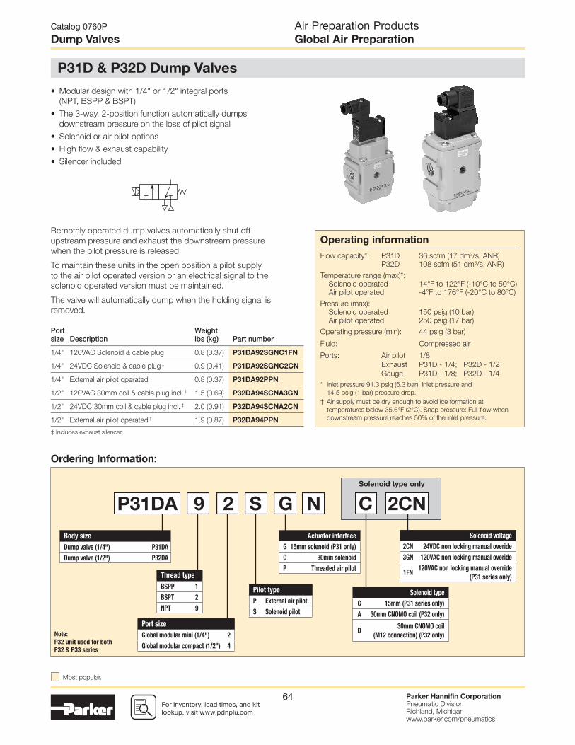
For inventory, lead times, and kit lookup, visit www.pdnplu.com
Parker Hannifi n CorporationPneumatic DivisionRichland, Michiganwww.parker.com/pneumatics
64
Remotely operated dump valves automatically shut off
upstream pressure and exhaust the downstream pressure
when the pilot pressure is released.
To maintain these units in the open position a pilot supply
to the air pilot operated version or an electrical signal to the
solenoid operated version must be maintained.
The valve will automatically dump when the holding signal is
removed.
Port size Description
Weightlbs (kg) Part number
1/4" 120VAC Solenoid & cable plug 0.8 (0.37) P31DA92SGNC1FN
1/4" 24VDC Solenoid & cable plug ‡ 0.9 (0.41) P31DA92SGNC2CN
1/4" External air pilot operated 0.8 (0.37) P31DA92PPN
1/2" 120VAC 30mm coil & cable plug incl. ‡ 1.5 (0.69) P32DA94SCNA3GN
1/2" 24VDC 30mm coil & cable plug incl. ‡ 2.0 (0.91) P32DA94SCNA2CN
1/2" External air pilot operated ‡ 1.9 (0.87) P32DA94PPN
• Modular design with 1/4" or 1/2" integral ports
(NPT, BSPP & BSPT)
• The 3-way, 2-position function automatically dumps
downstream pressure on the loss of pilot signal
• Solenoid or air pilot options
• High fl ow & exhaust capability
• Silencer included
‡ Includes exhaust silencer
Solenoid type only
Actuator interface
G 15mm solenoid (P31 only)
C 30mm solenoid
P Threaded air pilotThread type
BSPP 1
BSPT 2
NPT 9
Port size
Global modular mini (1/4") 2
Global modular compact (1/2") 4
Pilot type
P External air pilot
S Solenoid pilot
Body size
Dump valve (1/4") P31DA
Dump valve (1/2") P32DA
P31DA 9 2 S G N C 2CN
Solenoid voltage
2CN 24VDC non locking manual overide
3GN 120VAC non locking manual overide
1FN120VAC non locking manual override
(P31 series only)
Solenoid type
C 15mm (P31 series only)
A 30mm CNOMO coil (P32 only)
D30mm CNOMO coil
(M12 connection) (P32 only)Note:
P32 unit used for both
P32 & P33 series
Catalog 0760P
Dump Valves
P31D & P32D Dump Valves
Air Preparation ProductsGlobal Air Preparation
Ordering Information:
Operating information
Flow capacity*: P31D 36 scfm (17 dm3/s, ANR)
P32D 108 scfm (51 dm3/s, ANR)
Temperature range (max)†:
Solenoid operated 14°F to 122°F (-10°C to 50°C)
Air pilot operated -4°F to 176°F (-20°C to 80°C)
Pressure (max):
Solenoid operated 150 psig (10 bar)
Air pilot operated 250 psig (17 bar)
Operating pressure (min): 44 psig (3 bar)
Fluid: Compressed air
Ports: Air pilot 1/8
Exhaust P31D - 1/4; P32D - 1/2
Gauge P31D - 1/8; P32D - 1/4
* Inlet pressure 91.3 psig (6.3 bar), inlet pressure and
14.5 psig (1 bar) pressure drop.
† Air supply must be dry enough to avoid ice formation at
temperatures below 35.6°F (2°C). Snap pressure: Full fl ow when
downstream pressure reaches 50% of the inlet pressure.
Most popular.

For inventory, lead time, and kit lookup, visit www.pdnplu.com
Parker Hannifi n CorporationPneumatic DivisionRichland, Michiganwww.parker.com/pneumatics
65
P31DA 1/4" Remote Dump Valve
P32DA 1/2" Remote Dump Valve
Material Specifi cations
Body Aluminum
Body cover Polyester
Seals Nitrile NBR
Dimensions inches (mm)
Flow Charts
Inlet Pressure - 6.3 bar (91.3 psig)
Sec
onda
ry P
ress
ure
- (b
ar)
Sec
onda
ry P
ress
ure
- (p
sig)
0
20
40
60
80
100
2
3
4
5
6
7
8
1
0
0
10 15 25 55 60 706535 455 3020 40 50
Flow - (scfm)20 40 60 80 100 120 140
10 bar145 psig
5.0 bar72.5 psig4.0 bar
58 psig3.0 bar
43.5 psig
7 bar101.5 psig
8.0 bar116 psig
9.0 bar130.5 psig
6.0 bar87 psig
6.3 bar91.4 psig
Flow - (dm3/s) n
Inlet Pressure - 6.3 bar (91.3 psig)
Sec
onda
ry P
ress
ure
- (b
ar)
Sec
onda
ry P
ress
ure
- (p
sig)
0
20
40
60
80
100
0
2
3
4
5
6
7
8
1
0
0
20 40 1008060 140 150120
Flow - (scfm)40 160 200 24012080 280 320
8.0 bar116 psig
9.0 bar130.5 psig
10 bar145 psig
4.0 bar58 psig
5.0 bar72.5 psig
6.0 bar87 psig
6.3 bar91.4 psig
7 bar101.5 psig
3.0 bar43.5 psig
Flow - (dm3/s) n
Catalog 0760P
Dump Valves
Air Preparation ProductsGlobal Air Preparation
Most popular.
P31D P32D
1.57(40)
0.15(4)
0.94(24)
1.45(37)
2.24(57)
3.30(84)
1/8"GaugePort 1/4"
GaugePort
1.20(30.5)
5.35(136)
6.53(166)
2.53(64.5)
2.87(73)
8.95(227.3)
6.87(174.5)
2.95(75)
1.02(26)
0.23(6)2.25
(57.2)
2.08(53)
4.31(109.5)
Mounting Brackets
Description
Part number
P31D
L-bracket mounting kit P3HKA00ML
Foot bracket mounting kit P3HKA00MC
P31
P31
Note:For solenoid operators and cable plugs (connectors) see page B79 and B80.
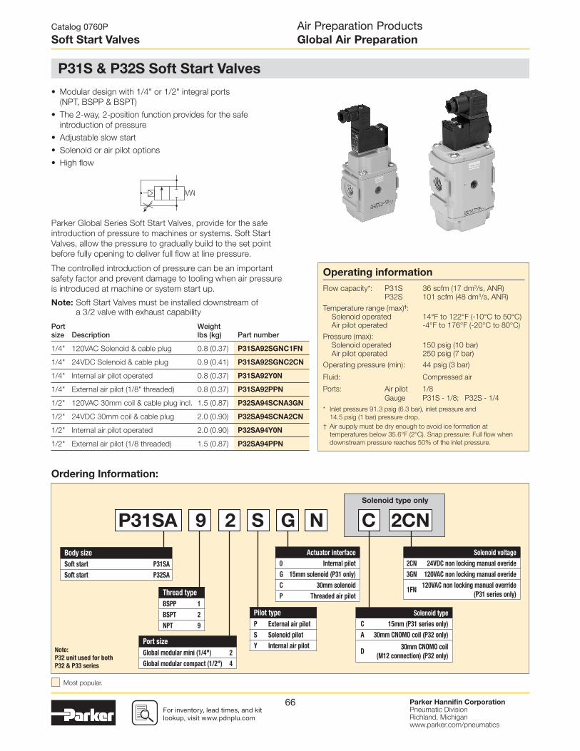
For inventory, lead times, and kit lookup, visit www.pdnplu.com
Parker Hannifi n CorporationPneumatic DivisionRichland, Michiganwww.parker.com/pneumatics
66
Port size Description
Weightlbs (kg) Part number
1/4" 120VAC Solenoid & cable plug 0.8 (0.37) P31SA92SGNC1FN
1/4" 24VDC Solenoid & cable plug 0.9 (0.41) P31SA92SGNC2CN
1/4" Internal air pilot operated 0.8 (0.37) P31SA92Y0N
1/4" External air pilot (1/8" threaded) 0.8 (0.37) P31SA92PPN
1/2" 120VAC 30mm coil & cable plug incl. 1.5 (0.87) P32SA94SCNA3GN
1/2" 24VDC 30mm coil & cable plug 2.0 (0.90) P32SA94SCNA2CN
1/2" Internal air pilot operated 2.0 (0.90) P32SA94Y0N
1/2" External air pilot (1/8 threaded) 1.5 (0.87) P32SA94PPN
Parker Global Series Soft Start Valves, provide for the safe
introduction of pressure to machines or systems. Soft Start
Valves, allow the pressure to gradually build to the set point
before fully opening to deliver full fl ow at line pressure.
The controlled introduction of pressure can be an important
safety factor and prevent damage to tooling when air pressure
is introduced at machine or system start up.
Note: Soft Start Valves must be installed downstream of a 3/2 valve with exhaust capability
• Modular design with 1/4" or 1/2" integral ports
(NPT, BSPP & BSPT)
• The 2-way, 2-position function provides for the safe
introduction of pressure
• Adjustable slow start
• Solenoid or air pilot options
• High fl ow
Solenoid type only
Thread type
BSPP 1
BSPT 2
NPT 9
Port size
Global modular mini (1/4") 2
Global modular compact (1/2") 4
Body size
Soft start P31SA
Soft start P32SA
P31SA 9 2 S G N C 2CN
Solenoid voltage
2CN 24VDC non locking manual overide
3GN 120VAC non locking manual overide
1FN120VAC non locking manual override
(P31 series only)
Solenoid type
C 15mm (P31 series only)
A 30mm CNOMO coil (P32 only)
D30mm CNOMO coil
(M12 connection) (P32 only)Note:
P32 unit used for both
P32 & P33 series
Actuator interface
0 Internal pilot
G 15mm solenoid (P31 only)
C 30mm solenoid
P Threaded air pilot
Pilot type
P External air pilot
S Solenoid pilot
Y Internal air pilot
Catalog 0760P
Soft Start Valves
Air Preparation ProductsGlobal Air Preparation
P31S & P32S Soft Start Valves
Ordering Information:
Operating information
Flow capacity*: P31S 36 scfm (17 dm3/s, ANR)
P32S 101 scfm (48 dm3/s, ANR)
Temperature range (max)†:
Solenoid operated 14°F to 122°F (-10°C to 50°C)
Air pilot operated -4°F to 176°F (-20°C to 80°C)
Pressure (max):
Solenoid operated 150 psig (10 bar)
Air pilot operated 250 psig (7 bar)
Operating pressure (min): 44 psig (3 bar)
Fluid: Compressed air
Ports: Air pilot 1/8
Gauge P31S - 1/8; P32S - 1/4
* Inlet pressure 91.3 psig (6.3 bar), inlet pressure and
14.5 psig (1 bar) pressure drop.
† Air supply must be dry enough to avoid ice formation at
temperatures below 35.6°F (2°C). Snap pressure: Full fl ow when
downstream pressure reaches 50% of the inlet pressure.
Most popular.
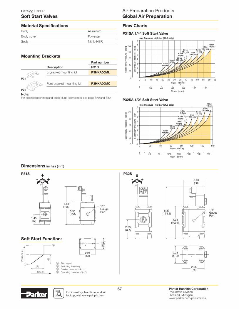
For inventory, lead time, and kit lookup, visit www.pdnplu.com
Parker Hannifi n CorporationPneumatic DivisionRichland, Michiganwww.parker.com/pneumatics
67
P31SA 1/4" Soft Start Valve
50%
Start signal1
2
3
4
Switching time delay
Gradual pressure build up
Operating pressure p2 (=p1)
P32SA 1/2" Soft Start Valve
Dimensions inches (mm)
Flow Charts
Inlet Pressure - 6.3 bar (91.3 psig)
Sec
onda
ry P
ress
ure
- (b
ar)
Sec
onda
ry P
ress
ure
- (p
sig)
0
20
40
60
80
100
2
3
4
5
6
7
8
1
0
0
10 15 25 55 60 6535 455 3020 40 50
Flow - (scfm)20 40 60 80 100 120
10 bar145 psig
5.0 bar72.5 psig4.0 bar
58 psig3.0 bar43.5 psig
7 bar101.5 psig
8.0 bar116 psig
9.0 bar130.5 psig
6.0 bar87 psig
6.3 bar91.4 psig
Flow - (dm3/s) n
Inlet Pressure - 6.3 bar (91.3 psig)
Sec
onda
ry P
ress
ure
- (b
ar)
Sec
onda
ry P
ress
ure
- (p
sig)
0
20
40
60
80
100
0
2
3
4
5
6
7
8
1
0
0
20 40 1008060 140120
Flow - (scfm)40 160 200 24012080 280
8.0 bar116 psig
9.0 bar130.5 psig
10 bar145 psig
4.0 bar58 psig
5.0 bar72.5 psig
6.0 bar87 psig
6.3 bar91.4 psig
7 bar101.5 psig
3.0 bar43.5 psig
Flow - (dm3/s) n
Soft Start Function:
Catalog 0760P
Soft Start Valves
Air Preparation ProductsGlobal Air Preparation
Material Specifi cations
Body Aluminum
Body cover Polyester
Seals Nitrile NBR
- +5 - +5
P31S P32S
1.57(40)
1.45(37)
2.24(57)
5.35(136)
6.53(166)
2.53(64.5)
3.46(88)
6.87(174.5)
2.95(75)
2.25(57.2)
4.31(109.5)
1/8"GaugePort
1/4"GaugePort
Mounting Brackets
Description
Part number
P31S
L-bracket mounting kit P3HKA00ML
Foot bracket mounting kit P3HKA00MC
P31
P31
Note:For solenoid operators and cable plugs (connectors) see page B79 and B80.

For inventory, lead times, and kit lookup, visit www.pdnplu.com
Parker Hannifi n CorporationPneumatic DivisionRichland, Michiganwww.parker.com/pneumatics
68
Port size Description
Weightlbs (kg) Part number
1/4" 120VAC Solenoid & cable plug 0.8 (0.37) P31TA92SGNC1FN
1/4" 24VDC Solenoid & cable plug 0.9 (0.41) P31TA92SGNC2CN
1/4" External air pilot operated 0.8 (0.37) P31TA92PPN
1/2" 120VAC 30mm coil & cable plug incl. 1.9 (0.87) P32TA94SCNA3GN
1/2" 24VDC 30mm coil & cable plug incl. 2.0 (0.91) P32TA94SCNA2CN
1/2" External air pilot operated 1.9 (0.87) P32TA94PPN
Parker Global Series Combined Soft Start / Dump Valves, provide for
the safe introduction of pressure to machines or systems. Soft Start
/ Dump Valves when set, allow the pressure to gradually build to the
set point before fully opening to deliver full fl ow at line pressure.
The controlled introduction of pressure can be an important safety
factor and prevent damage to tooling when air pressure is introduced
at machine or system start up.
To maintain these units in the open position a pilot supply to the air
pilot operated version or an electrical signal to the solenoid operated
version must be maintained. The valve will automatically dump when
the holding signal is removed.
• Modular design with 1/4" or 1/2" integral ports
(NPT, BSPP & BSPT)
• Provides for the safe introduction of pressure
• The 3-way, 2-position function automatically dumps
downstream pressure on the loss of pilot signal
• Adjustable slow start
• Solenoid or air pilot options
• High fl ow & exhaust capability
• Silencer included
Solenoid type only
Actuator interface
G 15mm solenoid (P31 only)
C 30mm solenoid
P Threaded air pilotThread type
BSPP 1
BSPT 2
NPT 9
Port size
Global modular mini (1/4") 2
Global modular compact (1/2") 4
Pilot type
P External air pilot
S Solenoid pilot
Body size
Soft start / dump valve (1/4") P31TA
Soft start / dump valve (1/2") P32TA
P31TA 9 2 S G N C 2CN
Solenoid voltage
2CN 24VDC non locking manual overide
3GN 120VAC non locking manual overide
1FN120VAC non locking manual override
(P31 series only)
Solenoid type
C 15mm (P31 series only)
A 30mm CNOMO coil (P32 only)
D30mm CNOMO coil
(M12 connection) (P32 only)Note:
P32 unit used for both
P32 & P33 series
Catalog 0760P
Combined Soft Start / Dump Valves
Air Preparation ProductsGlobal Air Preparation
P31T & P32T Combined Soft Start / Dump Valves
Ordering Information:
Operating information
Flow capacity*: P31T 36 scfm (17 dm3/s, ANR)
P32T 108 scfm (51 dm3/s, ANR)
Temperature range (max)†:
Solenoid operated 14°F to 122°F (-10°C to 50°C)
Air pilot operated -4°F to 176°F (-20°C to 80°C)
Pressure (max):
Solenoid operated 150 psig (10 bar)
Air pilot operated 250 psig (7 bar)
Operating pressure (min): 44 psig (3 bar)
Fluid: Compressed air
Ports: Air pilot 1/8
Exhaust P31T - 1/4; P32T - 1/2
Gauge P31T - 1/8; P32T - 1/4
* Inlet pressure 91.3 psig (6.3 bar), inlet pressure and
14.5 psig (1 bar) pressure drop.
† Air supply must be dry enough to avoid ice formation at
temperatures below 35.6°F (2°C). Snap pressure: Full fl ow when
downstream pressure reaches 50% of the inlet pressure.
Most popular.

For inventory, lead time, and kit lookup, visit www.pdnplu.com
Parker Hannifi n CorporationPneumatic DivisionRichland, Michiganwww.parker.com/pneumatics
69
P31TA 1/4" Soft Start & Dump Valve
P32TA 1/2" Soft Start & Dump Valve
50%
Start signal1
2
3
4
Switching time delay
Gradual pressure build up
Operating pressure p2 (=p1)
Dimensions inches (mm)
Flow Charts
Inlet Pressure - 6.3 bar (91.3 psig)
Sec
onda
ry P
ress
ure
- (b
ar)
Sec
onda
ry P
ress
ure
- (p
sig)
0
20
40
60
80
100
2
3
4
5
6
7
8
1
0
0
10 15 25 55 60 6535 455 3020 40 50
Flow - (scfm)20 40 60 80 100 120
10 bar145 psig
5.0 bar72.5 psig
4.0 bar58 psig
3.0 bar43.5 psig
7 bar101.5 psig
8.0 bar116 psig
9.0 bar130.5 psig
6.0 bar87 psig
6.3 bar91.4 psig
Flow - (dm3/s) n
Inlet Pressure - 6.3 bar (91.3 psig)
Sec
onda
ry P
ress
ure
- (b
ar)
Sec
onda
ry P
ress
ure
- (p
sig)
0
20
40
60
80
100
0
2
3
4
5
6
7
8
1
0
0
20 40 1008060 140120
Flow - (scfm)40 160 200 24012080 280
8.0 bar116 psig
9.0 bar130.5 psig
10 bar145 psig
4.0 bar58 psig
5.0 bar72.5 psig
6.0 bar87 psig
6.3 bar91.4 psig
7 bar101.5 psig
3.0 bar43.5 psig
Flow - (dm3/s) n
Soft Start Function:
Catalog 0760P
Combined Soft Start / Dump Valves
Air Preparation ProductsGlobal Air Preparation
Material Specifi cations
Body Aluminum
Body cover Polyester
Seals Nitrile NBR
Mounting Brackets
Description
Part number
P31T
L-bracket mounting kit P3HKA00ML
Foot bracket mounting kit P3HKA00MC
P31
P31
Note:For solenoid operators and cable plugs (connectors) see page B79 and B80.
- +5
P31T P32T
1.57(40)
0.15(4)
0.94(24)
1.45(37)
2.24(57)
3.30(84)
1.20(30.5)
5.35(136)6.53
(166)
- +5
2.53(64.5)
2.87(73)
8.95(227.3)
6.87(174.5)
2.95(75)
1.02(26)
0.23(6)2.25
(57.2)
2.08(53)
4.31(109.5)
1/8"GaugePort
1/4"GaugePort

For inventory, lead times, and kit lookup, visit www.pdnplu.com
Parker Hannifi n CorporationPneumatic DivisionRichland, Michiganwww.parker.com/pneumatics
70
Body size
Standard P33T
Thread type
BSPP 1
NPT 9
Solenoid
Dual M12 connector without transducer
F
Triple M12 connector with transducer
G
Voltage
24VDC withmanual override
2CN
Port size
3/4" 6
Type
Solenoid pilot + gauge
R
Operator
15mm Solenoid G
Mounting
Cat 4 w/bracket 4
P33T A 9 6 R G 4 F 2CN
Port size
Transducer
Cv
Part number*Inlet Outlet 1 to 2 2 to 3
3/4 3/4 w/o transducer 3.7 8.5 P33TA96RG4F2CN
3/4 3/4 w/ transducer 3.7 8.5 P33TA96RG4G2CN
* NPT port threads. For BSPP threads, replace “9” in the part number with a “1”.
21
3
• Proven control reliable technology with integrated soft start
• Soft start application of air to the system when energized; can
be adjusted for slower or faster buildup of system pressure
• Rapid exhaust of downstream air when de-energized to remove
stored energy and allow safe access
• Memory, monitoring, and air fl ow control functions are
integrated into two identical valve elements. Valves lock-out
if asynchronous movement of valve elements occurs during
actuation or de-actuation, resulting in a residual outlet pressure
of less than 1% of supply.
• Reset can only be accomplished by the integrated electrical
(solenoid) reset. Cannot be reset by removing and re-applying
supply pressure.
• Basic 3/2 normally closed valve function: Dirt tolerant, wear
compensating poppet design for quick response and high fl ow
capacity.
• LED indicators of main solenoid operation, reset solenoid
operation, and status indicator condition.
• Optional transducer for monitoring of downstream pressure in
the system.
• Dual exhaust silencers included.
• Not for use with clutch / brake applications.
• For use in conjunction with a safety relay or safety PLC.
Catalog 0760P
Redundant Safety Exhaust Valves
Air Preparation ProductsGlobal Air Preparation
Operating information
Pilot Solenoids: According to VDE 0580
Enclosure rating: According to DIN 400 50 IP65
Connector socket: According to DIN 43650 Form A
Three solenoids, rated for
continuous duty
Standard voltages: 24VDC
Power consumption 1.2 Watts on DC
(each solenoid), for
primary & reset solenoids:
Enclosure rating: IP65, IEC 60529
Electrical connection: M12, 5-pin
Ambient temperature: 15°F to 122°F (-10°C to 50°C)
Media temperature: 40°F to 175°F (4°C to 80°C)
Flow media: Compressed Air,
Filtered to Minimum 40 Micron
Inlet pressure: 30 to 150 psig (2 to 10 bar)
Monitoring: Dynamically, cyclically, internally
during each actuating and
de-actuating movement.
Monitoring function has memory
and requires an overt act to reset
unit after lockout.
Mounting orientation: Vertically with pilot solenoids on top
Port threads: 3/4 NPT, 3/4 BSPP
Control reliable: Category 4 (Cat 4); performance
Level e (PLe) in accordance with
Machine directive - EN ISO 13849-1
(Certifi cation pending)
Weight: 16.1 lb (7.3 kg) w/o transducer
16.3 lb (7.4 kg) w/ transducer
P33T Redundant Safety Exhaust Valve
Ordering Information:
Most popular.

For inventory, lead time, and kit lookup, visit www.pdnplu.com
Parker Hannifi n CorporationPneumatic DivisionRichland, Michiganwww.parker.com/pneumatics
71
10.78(273.8)
0.64(16.3)
5.73(145.5)
5.35 (136.0)5.81 (147.6)
AdjustableSoft Start
Inlet
Feedback PressureTransducer(Optional)
ControlSignal
Outlet
(+) Increase Time(-) Decrease Time
1.63 (41.3)
- +5
ManualReset
LEDStatusLights
SOL.1 SOL.2 STATUSRESETSOL
Dimensions inches (mm)
Valve Wiring
Black grill 1834C05-001
Body connector P32KA00CB
M12, 5-pin female to fl ying lead cable,
TPE; 6.6 ft (2 m) RKC 4.5T-2/S1587
M12, 5-pin male to fl ying lead cable,
TPE; 6.6 ft (2 m) RSC 4.5T-2/S1587
1/2 NPT, port block kit P32KA94CP
3/4 NPT, port block kit P32KA96CP
1/2 BSPP, port block kit P32KA14CP
3/4 BSPP, port block kit P32KA16CP
1/2 BSPT, port block kit P32KA24CP
3/4 BSPT, port block kit P32KA26CP
Pressure switch 1227A30-001
Pressure transducer (optional) 1232H30-001
T-bracket w/ body connector P32KA00MT
T-bracket (fi ts to body connector or port block) P32KA00MB
Silencer(s) 3/4" 5500A5013
Solenoid (main & reset) 1527B7916-001
Square fl ush mounting gauge kit, 0-160 psig K4511SCR160
Repair and Service Kits
0.75 (19.1)
0.375(9.5) 3.2 (81.3)0.34
(8.6)
0.25(6.4)
0.44(11.1)
3.0 (76.2)3.875 (98.4)
8XR 0.13 3.0
(76.2)
3.0 (76.2)
R0.063
90°1.82(46.2)
Angle Mounting Bracket
60%
0%
100%
Start signal1
2
3
4
Switching time delay
Gradual pressure build up
Operating pressure p2 (=p1)
Note: Mounting bracket and installation screws includedand required to install unit in the system.
1
4 3
2
3 4
12
5 5
BROWN(+24 Volts DC)
BROWN(+24 Volts DC)
GRAY(Equip Ground)
5 GRAYReset
WHITE(Sol 2)
WHITE(N.O. StatusContact)
BLACK(N.C. Status
Contact)
BLACK(Sol 1)
BLUE(Common)
BLUE(Common)
1
4 3
2
5-Pin “A” CodeFemale Connector
(Feedback)
5-Pin “A” Code Female Connector(Digital Pressure Transducer
Wiring (optional))
5-Pin “A” CodeMale Connector(Control Signal)
InputPower +
Power Input
DigitalOutput Signal
DigitalOutput 2 Signal
AnalogOutput Signal
Catalog 0760P
Redundant Safety Exhaust Valves
Air Preparation ProductsGlobal Air Preparation
Reset port
Pressure Switch
Exh.
Exh. Exh.
2
1
3

For inventory, lead times, and kit lookup, visit www.pdnplu.com
Parker Hannifi n CorporationPneumatic DivisionRichland, Michiganwww.parker.com/pneumatics
72
Valve de-actuated (ready-to-run):
Valve actuated:
12
EXHAUST
ADJUSTING NEEDLE
OUTLET
INLET
12
EXHAUSTADJUSTING NEEDLE
OUTLET
INLET
60%
0%
100%
Start signal1
2
3
4
Switching time delayGradual pressure build upOperating pressure p2 (=p1)
SOL.1 STATUSSOL.2 RESETSOL
SOL.1 STATUSSOL.2 RESETSOL
The fl ow of inlet air pressure to the inlet chamber of the main
valve internals is restricted by a fi xed orifi ce and an adjustable
fl ow control as well as an air piloted 2-way normally closed
poppet valve. The fl ow of inlet air pressure into the crossover
passages is restricted by the size of the passage between the
stem and the valve body opening. Flow is suffi cient to quickly
pressurize pilot supply / timing chambers 1 and 2. The inlet
poppets prevent air fl ow from crossover passages into the
outlet chamber. Air pressure acting on the inlet poppets and
return pistons securely hold the valve elements in the closed
position. (Reset adapter omitted for clarity.)
The green “Status” LED will be illuminated indicating the valve
is operational.
Soft start function:
Energizing the pilot valves simultaneously applies pressure
to both pistons, forcing the internal parts to move to their
actuated (open) position, where inlet air fl ow to crossover
passages is fully open, inlet poppets are fully open and
exhaust poppets are fully closed. The outlet is then
pressurized at a rate allowed by the fi xed orifi ce and the
adjusted fl ow control. Once the air pressure in the outlet
chamber reaches approximately 60% of inlet pressure, the
air piloted 2-way normally closed poppet valve opens fully
and the pressure in the inlet, crossovers, outlet, and timing
chambers are quickly equalized. The adjustable fl ow control
will control the time it takes for the outlet air pressure to reach
approximately 60% of inlet pressure.
De-energizing the pilots quickly causes the valve elements
to return to the ready-to-run position.
Solenoid 1, Solenoid 2 and the green “Status” LED’s will be
illuminated indicating the valve is operating properly.
Catalog 0760P
Redundant Safety Exhaust Valves
Air Preparation ProductsGlobal Air Preparation

For inventory, lead time, and kit lookup, visit www.pdnplu.com
Parker Hannifi n CorporationPneumatic DivisionRichland, Michiganwww.parker.com/pneumatics
73
Valve fault and lock-out:
Valve reset (electrical or manual):
12
EXHAUSTADJUSTING NEEDLE
OUTLET
INLET
12
EXHAUSTADJUSTING NEEDLE
OUTLET
INLET
SOL.1 STATUSSOL.2 RESETSOL
SOL.1 STATUSSOL.2 RESETSOL
SOL.1 STATUSSOL.2 RESETSOL
Inlet
ManualReset
Feedback PressureTransducer(Optional)
ControlSignal
Whenever the valve elements operate in a suffi ciently
asynchronous manner, either on actuation or de-actuation,
the valve will move to a locked-out position. In the locked-out
position, one crossover and its related timing chamber will
be exhausted, and the other crossover and its related timing
chamber will be fully pressurized. The valve element (side 2) that
is partially actuated has pilot air available to fully actuate it, but
no air pressure on the return piston to fully de-actuate the valve
element.
Air pressure in the crossover acts on the differential of side 2
stem diameters creating a latching force. Side 1 is in a fully closed
position, and has no pilot air available to actuate, but has full
pressure on the inlet poppet and return piston to hold the element
in the fully closed position. Inlet air fl ow on side 1 into its crossover
is restricted, and fl ows through the open inlet poppet on side 2,
through the outlet into the exhaust port, and from the exhaust port
to atmosphere. Residual pressure in the outlet is less than 1% of
inlet pressure. The return springs are limited in travel, and can only
return the valve elements to the intermediate (locked-out) position.
Suffi cient air pressure acting on the return pistons is needed to
return the valve elements to a fully closed position.
The red “Status” LED will be illuminated indicating the valve in fault
and lock-out must be reset
The reset procedure is as follows:
• Remove the electrical signals to the main coils
• Ensure there is air supplied to the valve
• Energize the reset solenoid for a minimum of 200 ms
• Allow a 200 ms delay after de-energizing the reset
solenoid and re-energizing the main solenoids
The valve will remain in the locked-out position, even if the inlet
air supply is removed and re-applied.
A remote reset signal must be applied to reset the valve. A
momentary, remote electrical signal must be applied to the
reset solenoid to apply pressure to the reset pistons in the valve.
Actuation of the reset piston physically pushes the main valve
elements to their closed position. Inlet air fully pressurizes the
crossovers and holds the inlet poppets on seat. Actuation of
the reset piston opens the reset poppet, thereby, immediately
exhausting pilot supply air, thus, preventing valve operation
during reset (Reset adapter added to illustration.). De-actuation
of reset pistons causes the reset poppets to close and pilot
supply to fully pressurize. Reset air pressure is applied by a 3/2
normally closed solenoid, or a manual push button mounted on
the reset adapter in the top valve cover.
The green “Status” LED will be illuminated once the valve
is reset.
Catalog 0760P
Redundant Safety Exhaust Valves
Air Preparation ProductsGlobal Air Preparation

For inventory, lead times, and kit lookup, visit www.pdnplu.com
Parker Hannifi n CorporationPneumatic DivisionRichland, Michiganwww.parker.com/pneumatics
74
The Ball / Lockout Valve shuts off downstream line pressure
in the closed position with a 90° turn of the handle. In the
closed position, inlet air pressure is blocked and downstream
/ system air is exhausted through a threaded port. To
prevent unauthorized adjustment, the padlock slide may be
assembled on either side. It is recommended that this slide is
installed after fi nal system assembly.
The Safety Lockout valves conform to OSHA #29 CFR part
1910 — control of hazardous energy source (lockout / tagout).
Note: This padlock slide is a permanent assembly and may not be
removed later, any unauthorized tampering will void any
warranty claims. The valve can only be locked in the closed
position.
Ordering Information
Material Specifi cations
Body Aluminum
Seals PTFE
Ball Stainless Steel
Lockout Tab Zinc Plated Steel
Screw Zinc Plated Steel
For thread type: BSPP 1
BSPT 2
NPT 9
Dimensions inches (mm)
Model type
Portsize
Exhaust port
Threadtype
Flow scfm (dm3/s, ANR)
Modular ball valve fl ow from left to right
P31 1/4" 1/4" NPT 42.4 (20) P31VB92LBNN
P32 3/8" 1/4" NPT 190.7 (90) P32VB93LBNN
1/2" 1/4" NPT 258.5 (122) P32VB94LBNN
P33 1/2" 1/2" NPT 561.5 (265) P33VB94LBNN
3/4" 1/2" NPT 678 (320) P33VB96LBNN
* Lockout tab and muffl er supplied with unit.
Catalog 0760P
Accessories
Air Preparation ProductsGlobal Air Preparation
Ball Valve / Lockout Valve
Operating information
Operating temperature: -40°C to 80°C (-40°F to 176°F)
Pressure supply (max): 250 psig (17 bar)
Port size:
BSPP / BSPT / NPT 1/4, 3/8, 1/2, 3/4
Weight: P31 0.33 lbs (0.15 kg)
P32 0.79 lbs (0.36 kg)
P33 1.21 lbs (0.55 kg)
P31 P32 P33
0.82(21)
0.78(20)
1.65(42)
1.57(40)
2.81(71.4)
1.96(50)
0.84(21.4)
2.36(60)
1.18(30)
(2.36(60)
1.18(30)
3.46(88)
2.87(73)
1.00(25.4)
1.43(36.5)
2.87(73)
1.43(36.5)
2.87(73)
3.25(82.6)
3.87(98.4)
1.44(36.5)
1/4 ThreadPort
1/2 ThreadPort
1/4 ThreadPort
(
Most popular.
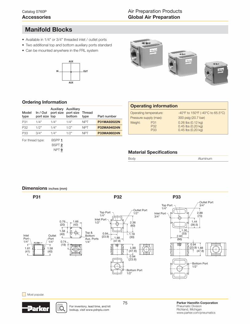
For inventory, lead time, and kit lookup, visit www.pdnplu.com
Parker Hannifi n CorporationPneumatic DivisionRichland, Michiganwww.parker.com/pneumatics
75
• Available in 1/4" or 3/4" threaded inlet / outlet ports
• Two additional top and bottom auxiliary ports standard
• Can be mounted anywhere in the FRL system
Ordering Information
Modeltype
In / Outport size
Auxiliaryport sizetop
Auxilliaryport sizebottom
Threadtype Part number
P31 1/4" 1/4" 1/4" NPT P31MA92022N
P32 1/2" 1/4" 1/2" NPT P32MA94024N
P33 3/4" 1/4" 1/2" NPT P33MA96024N
P32 P33P31
For thread type: BSPP 1
BSPT 2
NPT 9
Dimensions inches (mm)
Catalog 0760P
Accessories
Air Preparation ProductsGlobal Air Preparation
Material Specifi cations
Body Aluminum
Manifold Blocks
Operating information
Operating temperature: -40°F to 150°F (-40°C to 65.5°C)
Pressure supply (max): 300 psig (20.7 bar)
Weight: P31 0.26 lbs (0.12 kg)
P32 0.45 lbs (0.20 kg)
P33 0.45 lbs (0.20 kg)
Inlet Port3/4"
InletPort1/4"
OutletPort1/4"
Top Port1/4"
Top &BottomAux. Ports1/4"
Bottom Port1/2"
Outlet Port3/4"
2.88(73)
1.44(36.5)
1.88(47.8)
0.94(23.9)
2.60(66)
1.58(40)
1.58(40)
1.61(41)
FLOW 0.74(19)
1.66(42)
0.79(20)
1.30(33)
Inlet Port1/2"
Top Port1/4"
Bottom Port1/2"
Outlet Port1/2"
2.36(60)
1.18(30)
1.88(47.8)
0.94(23.9)
1.88(47.8)
0.94(23.9)
Most popular.

For inventory, lead times, and kit lookup, visit www.pdnplu.com
Parker Hannifi n CorporationPneumatic DivisionRichland, Michiganwww.parker.com/pneumatics
76
PPS1 1- -C 3 R HM
Set Point Direction
R Rising
Operation
The pressure switch monitors
the air pressure in your
pneumatic system. When the
pressure in your system either
drops below or exceeds the
set point pressure, an electrical
output is given.
3 (Normally Open)
2 (Normally Closed)1
(Common)
➤
➤
➤
• Long life elastomer diaphragm
• High quality snap action switch
• Field adjustable
• Compact design
• Easily customized
• Quick delivery
• NEMA 4, 13
Thread
1/4" NPT male 1
1/8" NPT male 2
1/4" BSPP male 17
1/8" BSPP male 18Range*
1 3-10 PSI
2 6-30 PSI
3 20-120 PSI
4 † 100-400 PSI† Only available in 1/4" NPT
Electrical Connection
HM DIN 9.4mm
WL Wire leads 18"
Circuit
SPDT C
Note: Switch is fi eld adjustable.
* Factory setting for calibration purposes
Range 1 = 6 PSI
Range 2 = 18 PSI
Range 3 = 70 PSI
Range 4 = 250 PSI
Ordering Information:
Catalog 0760P
Accessories
Air Preparation ProductsGlobal Air Preparation
Material Specifi cations
Adjustment knob Anodized aluminum
Body Brass
Diaphragm Nitrile
PPS1 Pressure Switch
Operating information
Temperature range: -40°F to 105°F (-40°C to 220°C)
Operating pressure range: 1, 2, 3 - 250 PSI (17.2 bar)
4 - 2000 PSI (137.9 bar)
Set point tolerance ±1 PSI or 5% (.07 bar)
Deadband 10 - 20% of set pressure
Current rating 3A @ 125 VAC
2A @ 30 VDC (Resistive)
Circuit form SPDT Standard
Cycle life 1 Million
Defi nitions and Terminology
Repeatability — Accuracy is the maximum allowable set
point deviation of a single pressure or temperature switch
under one given set of environmental and operational
conditions.
Single Pole Double Throw (SPDT) Switching element —A SPDT switching element has one normally open, one
normally closed and one common terminal. Three terminals
mean that the switch can be wired with the circuit either
normally open (NO), or normally closed (NC), or both.
Dead Band — The dead band, sometimes referred to as
“differential” or “hysteresis”, is the change in pressure between
actuation and deactuation set points.
1.20(30.5)
Ø
18" Leads
1-1/8 Hex
2.50(63.5)Max.
2.30(58.4)Max.
1.50(38.1)
1GND
2
3
Top View DINWire Configuration Pin 1 - Common (Black) Pin 2 - N.C. (Blue) Pin 3 - N.O. (Red)
Pin Configuration Pin 1 - Common (Black) Pin 2 - N.C. (Blue) Pin 3 - N.O. (Red)
1/8-27 NPT
1-1/8 Hex
1/4-18 NPTF

For inventory, lead time, and kit lookup, visit www.pdnplu.com
Parker Hannifi n CorporationPneumatic DivisionRichland, Michiganwww.parker.com/pneumatics
77
Port Block Kit w/ T-Bracket(O-ring not shown)
1/8 NPT ................. P31KA91CN
1/4 NPT ................ P31KA92CN
3/8 NPT ................. P31KA93CN
1/8 BSPP ............... P31KA11CN
1/4 BSPP .............. P31KA12CN
3/8 BSPP ............... P31KA13CN
1/8 BSPT .............. P31KA21CN
1/4 BSPT ............. P31KA22CN
3/8 BSPT .............. P31KA23CN
1/8 BSPT ............... P31KA21CP
1/4 BSPT .............. P31KA22CP
3/8 BSPT ............... P31KA23CP
Port Block Kit(O-ring not shown)
1/8 NPT ................ P31KA91CP
1/4 NPT ............... P31KA92CP
3/8 NPT ................ P31KA93CP
1/8 BSPP .............. P31KA11CP
1/4 BSPP .............. P31KA12CP
3/8 BSPP .............. P31KA13CP
C-Bracket(Fits to fi lter and lubricator body)
P31KA00MW
T-Bracket w/ Body Connector(O-ring not shown)
P31KA00MT
Angle Bracket(Fits to regulator and fi lter/regulator body)
P31KB00MR
Body Connector(O-ring not shown)
P31KA00CB
Catalog 0760P
Accessories
Air Preparation ProductsGlobal Air Preparation
P31 Accessories
2.67(68)
1.20(30.4)
Dia.
1.73(44)
0.98(25)
0.67(17)
1.57(40)
2.40(61)
0.27(7)
2.68(68)1.67(42.5)0.39(10)
0.26(6.6)
2.44(62)
2.36(60) 1.57
(40)
1.57(40)
0.08(2)
0.76(19.3)
1.40(35.5)
Dia
1.42(36)
0.39(10)
0.94(24)
0.28(7)
0.22(5.5)
0.39(10)
0.39(10)
0.63(16)
3.54(90)

For inventory, lead times, and kit lookup, visit www.pdnplu.com
Parker Hannifi n CorporationPneumatic DivisionRichland, Michiganwww.parker.com/pneumatics
78
T-Bracket w/ Body Connector
P32KA00MT
Body Connector
P32KA00CB
Port Block Kit1/4 NPT .................. P32KA92CP
3/8 NPT .................. P32KA93CP
1/2 NPT .................. P32KA94CP
3/4 NPT .................. P32KA96CP
1/4 BSPP .............. P32KA12CP
3/8 BSPP ............... P32KA13CP
1/2 BSPP ............... P32KA14CP
3/4 BSPP ............... P32KA16CP
1/4 BSPT .............. P32KA22CP
3/8 BSPT .............. P32KA23CP
1/2 BSPT .............. P32KA24CP
3/4 BSPT .............. P32KA26CP
T-Bracket (fi ts to body connector or port block)
P32KA00MB
Angle Bracket(Fits to regulator and fi lter/regulator bonnet)
P32KB00MR
L-Bracket(Fits to fi lter and lubricator body)
P32KA00ML
Catalog 0760P
Accessories
Air Preparation ProductsGlobal Air Preparation
P32 Accessories
4.53(115)
1.00(25.4)
0.29(7.5)
(Typ.)0.75(19)
0.28(7.0)
0.79(20)
2.74(69.5)
1.66(42)
2.84(72)
0.88(22)
1.10(28)
1.26(32)
2.25(57)
0.28(7.1)
0.38(9.6)
0.54(14)
Dia
1.57(40)
1.66(42.2)
2.83(72)
2.74(69.6)
1.11(28.3)
1.57(39.9)
1.91(48.5)
0.28(7.15)
0.37(9.5)
0.54(13.7)
Dia
0.87(22.1)
0.35(8.9)
Dia.
O-Ring
O-Ring 0.87(22.1)
0.35(8.9)
Dia.O-Ring
O-Ring

For inventory, lead time, and kit lookup, visit www.pdnplu.com
Parker Hannifi n CorporationPneumatic DivisionRichland, Michiganwww.parker.com/pneumatics
79
Port Block Kit1/4 NPT .................. P32KA92CP
3/8 NPT .................. P32KA93CP
1/2 NPT .................. P32KA94CP
3/4 NPT .................. P32KA96CP
1/4 BSPP .............. P32KA12CP
3/8 BSPP ............... P32KA13CP
1/2 BSPP ............... P32KA14CP
3/4 BSPP ............... P32KA16CP
1/4 BSPT .............. P32KA22CP
3/8 BSPT .............. P32KA23CP
1/2 BSPT .............. P32KA24CP
3/4 BSPT .............. P32KA26CP
T-Bracket w/ Body Connector
P32KA00MT
Body Connector
P32KA00CB
T-Bracket (fi ts to body connector or port block)
P32KA00MB
Angle Bracket(Fits to regulator and fi lter/regulator
bonnet)
P33KA00MR
L-Bracket(Fits to fi lter and lubricator body)
P33KA00ML
76(3.00)
48(1.88)
87(3.44)
28(1.10)
28(1.10)
38(1.49)
67.5(2.66)
7.1(.28)
9.6(.38)
14(.56)
Dia
Catalog 0760P
Accessories
Air Preparation ProductsGlobal Air Preparation
P33 Accessories
4.53(115)
1.00(25.4)
0.29(7.5)
(Typ.)0.75(19)
0.28(7.0)
0.79(20)
1.57(40)
0.87(22.1)
0.35(8.9)
Dia.
O-Ring
O-Ring 0.87(22.1)
0.35(8.9)
Dia.O-Ring
O-Ring
2.99(76)
1.89(48)
3.33(84.5)
0.98(25)
1.92(49)
2.40(61)
2.40(61)
0.43(11)
0.55(14)
Dia

For inventory, lead times, and kit lookup, visit www.pdnplu.com
Parker Hannifi n CorporationPneumatic DivisionRichland, Michiganwww.parker.com/pneumatics
80
Series Description Part number
P31
P32
P33
Panel Mount Nut (Plastic)
P31KA00MP
P32KA00MP
P33KA00MP
P31
P32
P33
Panel Mount Nut (Aluminum)
P31KA00MM
P32KA00MM
P33KA00MM
P31
P32
P33
5µ Element Kit
P31KA00ESE
P32KA00ESE
P33KA00ESE
P31
P32
P33
1µ Element Kit
P31KA00ES9
P32KA00ES9
P33KA00ES9
P31
P32
P33
0.01µ Element Kit
P31KA00ESC
P32KA00ESC
P33KA00ESC
P31
P32
P33
Adsorber Element Kit
P31KA00ESA
P32KA00ESA
P33KA00ESA
P32 / P33 Auto Drain Kit P32KA00DA
P31
P32 / P33Differential Pressure Indicator Kit
P31KB00RQ
P32KA00RQ
P31 / P32 / P33 Drip Control Assembly Kit P32KA00PH
P31
P32 / P33Fill Plug Kit
P31KA00PL
P32KA00PL
P31
P32
P33
Lubricator - Plastic Bowl w/ Bowl Guard No Drain
P31KB00BGN
P32KB00BGN
P33KA00BGN
Catalog 0760P
Accessories
Air Preparation ProductsGlobal Air Preparation

For inventory, lead time, and kit lookup, visit www.pdnplu.com
Parker Hannifi n CorporationPneumatic DivisionRichland, Michiganwww.parker.com/pneumatics
81
Series Description Part number
P31
P32
P33
Lubricator - Metal Bowl w/o Sight Gauge No Drain
P31KB00BMN
P32KB00BMN
P33KA00BMN
P32
P33Lubricator - Metal Bowl w/ Sight Gauge No Drain
P32KB00BSN
P33KA00BSN
P31
P32
P33
Metal Bowl w/o Sight Gauge & Manual Drain
P31KB00BMM
P32KB00BMM
P33KA00BMM
P31 Metal Bowl w/o Sight Gauge & Pulse Drain P31KB00BMB
P32
P33Metal Bowl w/o Sight Gauge & Auto Drain
P32KB00BMA
P33KA00BMA
P32
P33Metal Bowl w/ Sight Gauge & Manual Drain
P32KB00BSM
P33KA00BSM
P32
P33Metal Bowl w/ Sight Gauge & Auto Drain
P32KB00BSA
P33KA00BSA
P31
P32
P33
Plastic Bowl w/ Bowl Guard & Manual Drain
P31KB00BGM
P32KB00BGM
P33KA00BGM
P31 Plastic Bowl w/ Bowl Guard & Pulse Drain P31KB00BGB
P32
P33Plastic Bowl w/ Bowl Guard & Auto Drain
P32KB00BGA
P33KA00BGA
P31
P32
P33
Regulator - Relieving Repair Kit
P31KB00RB
P32KB00RB
P33KA00RB
P31
P32
P33
Regulator - Non-Relieving Repair Kit
P31KB00RC
P32KB00RC
P33KA00RC
Catalog 0760P
Accessories
Air Preparation ProductsGlobal Air Preparation
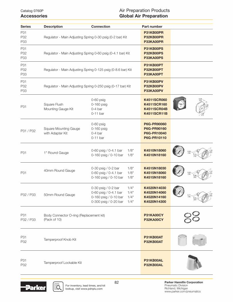
For inventory, lead times, and kit lookup, visit www.pdnplu.com
Parker Hannifi n CorporationPneumatic DivisionRichland, Michiganwww.parker.com/pneumatics
82
Series Description Connection Part number
P31
P32
P33
Regulator - Main Adjusting Spring 0-30 psig (0-2 bar) Kit
P31KB00PR
P32KB00PR
P33KA00PR
P31
P32
P33
Regulator - Main Adjusting Spring 0-60 psig (0-4.1 bar) Kit
P31KB00PS
P32KB00PS
P33KA00PS
P31
P32
P33
Regulator - Main Adjusting Spring 0-125 psig (0-8.6 bar) Kit
P31KB00PT
P32KB00PT
P33KA00PT
P31
P32
P33
Regulator - Main Adjusting Spring 0-250 psig (0-17 bar) Kit
P31KB00PV
P32KB00PV
P33KA00PV
P31Square Flush
Mounting Gauge Kit
0-60 psig
0-160 psig
0-4 bar
0-11 bar
K4511SCR060
K4511SCR160
K4511SCR04B
K4511SCR11B
P31 / P32Square Mounting Gauge
with Adapter Kit
0-60 psig
0-160 psig
0-4 bar
0-11 bar
P6G-PR90060
P6G-PR90160
P6G-PR10040
P6G-PR10110
P31 1" Round Gauge0-60 psig / 0-4.1 bar
0-160 psig / 0-10 bar
1/8"
1/8"
K4510N18060
K4510N18160
P3140mm Round Gauge
0-30 psig / 0-2 bar
0-60 psig / 0-4.1 bar
0-160 psig / 0-10 bar
1/8"
1/8"
1/8"
K4515N18030
K4515N18060
K4515N18160
P32 / P33 50mm Round Gauge
0-30 psig / 0-2 bar
0-60 psig / 0-4.1 bar
0-160 psig / 0-10 bar
0-300 psig / 0-20 bar
1/4"
1/4"
1/4"
1/4"
K4520N14030
K4520N14060
K4520N14160
K4520N14300
P31
P32 / P33
Body Connector O-ring (Replacement kit)
(Pack of 10)
P31KA00CY
P32KA00CY
P31
P32Tamperproof Knob Kit
P31KB00AT
P32KB00AT
P31
P32Tamperproof Lockable Kit
P31KB00AL
P32KB00AL
Catalog 0760P
Accessories
Air Preparation ProductsGlobal Air Preparation
1.06(27)
1.06(27)
0.59(15)
0.75(19)
1.25(32)0.63
(16)
0.98(25)
1.57(40)0.63
(16)
0.94(24)
1.97(50)0.71
(18)

For inventory, lead time, and kit lookup, visit www.pdnplu.com
Parker Hannifi n CorporationPneumatic DivisionRichland, Michiganwww.parker.com/pneumatics
83
Materials
Solenoid operators, coil combinations
Pilot Valve
Body: Polyamide
Armature tube: Brass
Plunger & core: Corrosion resistant Cr-Ni steel
Seals: Fluorocarbon
Screws: Stainless steel
Coil
Encapsulation material: Thermoplastic as standard
Duroplast for M12 connection
Transients
Interrupting the current through the solenoid coil produces
momentary voltage peaks which, under unfavorable
conditions, can amount to several hundred times the rated
operating voltage. Normally, these transients do not cause
problems, but to achieve the Maximum life of relays in the
circuit (and particularly of transistors, thyristors and integrated
circuits) it is desirable to provide protection by means of
voltage-dependent resistors (varistors). All connectors/cable
plugs EN175301-803 with LED’s include this type of circuit
protection.
Solenoid Coils with M12 Connection
Solenoid Coils with DIN A or Industrial B Connection
Note: Solenoid pilot operators are fi tted to the Global range. Order the
above part numbers for spares. The operators are supplied with
mounting screws and interface ‘O’ rings. Coils and connectors must
be ordered separately.
Voltage
22mm x 30mmPart numberB industrial standard
Weight(Kg)
30mm x 30mmPart numberDIN 43650Astandard
Weight(Kg)
Direct current
24VDC P2FCB449 0.093 P2FCA449 0.105
Alternative current
110V 50Hz, 120V 60Hz P2FCB453 0.093 P2FCA453 0.105
Voltage Part numberWeight(Kg)
Direct current
24VDC P2FC6449 0.065
Spare Base Solenoid Pilot Operator
CNOMO NC
Description
Part number non-lock manual override
Weight(Kg)
Standard Duty P2FP23N4B 0.065
No Override P2FP23N4A 0.065
NC Normal Operatorwith 22 x 30
standard coil
NC Normal Operatorwith 30 x 30
standard coil
Working pressure 0 to 10 bar 0 to 10 bar
Ambient
temperature-10°C to 60°C * -10°C to 60°C *
Power (DC) 4.8W 2.7W
Power (AC) 8.5VA 4.9VA
Voltage tolerance +/-10% +/-10%
Duty cycle 100% 100%
Insulation class F F
Electric connection B Industrial DIN 43650A
Protection IP65 IP65
Approval UL/CSA
Working media All neutral media such as compressed air
* Limited to 50°C if use with 100% duty cycle
Voltage
Order code Override, blue,non-locking fl ush
Weight (Kg)
24VDC PS2982B49P 0.038
115VAC 50Hz /
120VAC 60Hz
PS2982B53P 0.038
01
1‰
‰
P31 Series only - Solenoid coils 15mm NC
Catalog 0760P
Accessories
Air Preparation ProductsGlobal Air Preparation
Solenoid Operators - CNOMO
Most popular.

For inventory, lead times, and kit lookup, visit www.pdnplu.com
Parker Hannifi n CorporationPneumatic DivisionRichland, Michiganwww.parker.com/pneumatics
84
30mm DIN 43650ACable plugs PS2028BP
Solenoid Connectors / Cable Plugs EN175301-803
Description
Part number22mm Form B
Industrial
Part number30mm Form A
DIN 43650A
With standard screw Standard IP65 without fl ying lead PS2429BP PS2028BP
With LED and protection 24VAC/DC PS243079BP PS203279BP
With LED and protection 110VAC PS243083BP PS203283BP
With cable Standard with 2m cable IP65 PS2429JBP PS2028JCP
24VAC/DC, 2m cable LED and protection IP65 PS2430J79BP PS2032J79CP
110VAC/DC, 2m cable LED and protection IP65 PS2430J83BP PS2032J83CP
Cable plug dimensions inches (mm)
Solenoid coil dimensions inches (mm)
22 x 30mm15mm
30 x 30mm
PS2028BP
PS2028JBP
PS2429BP
PS2429JBP
PS2932BP
PS2932JBP
PS243079BP PS203279BP
PS2430J79BP PS2032J79CP
PS243083BP PS203283BP
PS2430J83BP PS2032J83CP
PS294679BP PS294683BP
PS2946J79BP PS2946J83BP
Electrical schematics
Catalog 0760P
Accessories
Air Preparation ProductsGlobal Air Preparation
22mm Form B Industrial Cable plugs PS2429BP
01
1
1.57(40)
0.93(23.62)
0.13(3.4)1.00
(25.4)
0.59(15)
1.18(30)
1.77(45)
1.61(41)
1.22(31)
1.30(33)
0.87(22)
2.36(60)
2.01(51)
0.86(22)
1.89(48)
1.42(36)
1.18(30)
1.22(31)
0.87(22)
2.36(60)
2.05(52)
1.26(32)
1.22(31)
1.22(31)
1.65(42)1.87
(47.5)
0.20(5)
M3
1.18(30)
1.22(31)
1.57(40)
0.82(20.8)
0.22(5.5)
1.18(30)
Most popular.
For inventory, lead time, and kit lookup, visit www.pdnplu.com
Parker Hannifi n CorporationPneumatic DivisionRichland, Michiganwww.parker.com/pneumatics
85
Catalog 0760P Air Preparation Products

For inventory, lead times, and kit lookup, visit www.pdnplu.com
Parker Hannifi n CorporationPneumatic DivisionRichland, Michiganwww.parker.com/pneumatics
86
Catalog 0760P Air Preparation Products

For inventory, lead time, and kit lookup, visit www.pdnplu.com
Parker Hannifi n CorporationPneumatic DivisionRichland, Michiganwww.parker.com/pneumatics
87
The P3Y system allows units to be connected together
without the use of pipe connectors. This saves space,
provides constant mounting centers, and maintains a
modern aesthetically pleasing appearance.
The P3Y fi lters are specially designed to effi ciently fi lter out
rust, dirt, moisture and other impurities from compressed
air lines. Operation is fully automatic with a minimum of
pressure drop. Coalescing fi lters and adsorber fi lters for
high purity air are also included in the P3Y series.
The P3Y regulators are designed to provide quick
response and accurate pressure regulation for the most
demanding hi-fl ow industrial applications.
The rolling diaphragm was designed for long trouble-free
operation and will not rupture or tear under high cycle
or demanding applications. The P3Y mist lubricators are
designed to provide lubrication for many general purpose
applications.
Regulator
Wall mounting bracket
Lubricator can be fi lled under pressure to eliminate downtime
5 micron fi lter element as standard
Wall mounting bracket
All units body ported
Neck mounting bracket
Neck mounting nut
Bodyconnectorkit
Flowdirectional arrows
Combined manual / semi-auto drain &auto drain options
Metal bowl with chemical resistant sight glass
Non rising control knob
Constant density lubrication
Nitrile ‘O’ ring seal
Catalog 0760P
Features
Air Preparation ProductsP3Y Series
P3Y System

For inventory, lead times, and kit lookup, visit www.pdnplu.com
Parker Hannifi n CorporationPneumatic DivisionRichland, Michiganwww.parker.com/pneumatics
88
• Integral 3/4" or 1" ports (NPT & BSPP)
• High effi ciency particulate element as standard
• Excellent water removal effi ciency
• Robust but lightweight aluminium construction
• Low temperature -40°C (-40°F) with combined manual /
semi-auto drain as standard
Portsize Description Part number
3/4" Combined manual /semi-auto drain P3YFA96ESCN
3/4" Auto drain P3YFA96ESAN
1" Combined manual /semi auto drain P3YFA98ESCN
1" Auto drain P3YFA98ESAN
Ordering Information:
1 221
Manual drain Auto drain
Port size
3/4 6
1 8
Drain type
SCCombined manual
/ semi-auto drain
SA Auto drain
Element
E 5 micron
Basic series
Filter P3YFA
P3YFA 9 6 E SC N
* Note: For 1-1/2" ported unit, please order P3YKA*BCP port block kit separately.
Thread type*
BSPP 1
NPT 9
P3Y Particulate Filter
Operating information
Supply pressure (max)*: 254 psig (17.5 bar)
Operating temperature:
Auto drain 14°F to 140°F (-10°C to 60°C)
Combined drain -40°F to 140°F (-40°C to 60°C)
Standard fi ltration 5 micron
Manual / semi-auto drain: Closed at 11.6 psig (0.8 bar)
G1/8 thread male
Auto drain bowl pressure: Closed at 11.6 psig (0.8 bar)
Bowl capacity: 4.4 US oz. (130 cm3)
Standard fi ltration: 5 micron
Flow capacity†: 3/4" 170 scfm (80.2 dm3/s, ANR)
1" 170 scfm (80.2 dm3/s, ANR)
Fluid: Compressed air
Weight: 1.98 lb (0.9 kg)
† Inlet pressure 91.4 psig (6.3 bar) inlet pressure and 7.3 psig (0.5 bar)
pressure drop.
* Air supply must be dry enough to avoid ice formation at temperatures
below 35.6°F (2°C).
Air quality:
Within ISO 8573-1: 1991 Class 3 and 5 (Particulates)
Within ISO 8573-1: 2001 Class 6 and 7 (Particulates)
Catalog 0760P
Particulate Filter
Air Preparation ProductsP3Y Series
Most popular.
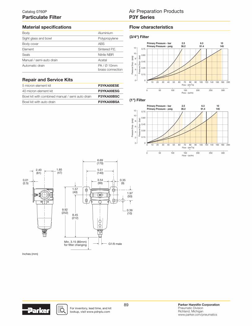
For inventory, lead time, and kit lookup, visit www.pdnplu.com
Parker Hannifi n CorporationPneumatic DivisionRichland, Michiganwww.parker.com/pneumatics
89
(3/4") Filter
(1") Filter
Flow characteristicsMaterial specifi cations
Body Aluminium
Sight glass and bowl Polypropylene
Body cover ABS
Element Sintered P.E.
Seals Nitrile NBR
Manual / semi-auto drain Acetal
Automatic drain PA / Ø 10mm
brass connection
Repair and Service Kits
5 micron element kit P3YKA00ESE
40 micron element kit P3YKA00ESG
Bowl kit with combined manual / semi auto drain P3YKA00BSC
Bowl kit with auto drain P3YKA00BSA
2.5
36.2
Primary Pressure - bar
Primary Pressure - psig
6.3
91.4
10
145
0 10 20 30 40 50 60 70 80 90 100 120 140 160 180 200
Pre
ssur
e D
rop
- (b
ar)
0
12
10
8
6
4
2
0
0.75
0.60
0.45
0.30
0.15Pre
ssur
e D
rop
- (p
sig)
0Flow - (scfm)
50 100 150 200 250 300
Flow - (dm3/s)
n
2.5
36.2
Primary Pressure - bar
Primary Pressure - psig
6.3
91.4
10
145
0 10 20 30 40 50 60 70 80 90 100 120 140 160 180 200
Pre
ssur
e D
rop
- (b
ar)
0
12
10
8
6
4
2
0
0.75
0.60
0.45
0.30
0.15Pre
ssur
e D
rop
- (p
sig)
0Flow - (scfm)
50 100 150 200 250 300
Flow - (dm3/s)
n
Catalog 0760P
Particulate Filter
Air Preparation ProductsP3Y Series
8.45(212)
9.92(252)
1.57(40)
G1/8 male
0.35(9)
0.01(2.5)
2.40(61)
1.85 (47)
1.97(50)
0.39(10)
3.54(90)
6.69(170)
5.51(140)
Min. 3.15 (80mm) for filter changing
Inches (mm)

For inventory, lead times, and kit lookup, visit www.pdnplu.com
Parker Hannifi n CorporationPneumatic DivisionRichland, Michiganwww.parker.com/pneumatics
90
• Extended high effi ciency fi lter element provides greater
fi ltration surface area.
• Integral 3/4" or 1" ports (BSPP & NPT)
• Removes liquid aerosols and sub micron particles
• Oil free air for critical applications, such as air gauging,
pneumatic instrumentation and control
• Adsorber activated carbon element removes oil vapors and
most hydrocarbons
• Robust but lightweight aluminum construction
Notes: To optimize the life of the coalescing element, it is advisable to
install a P3YFA pre-fi lter with a 5 micron element upstream of
the coalescing fi lter.
To optimize the life of the adsorber element, it is advisable to
install a P3Y coalescing 0.01 micron fi lter upstream of the
adsorber fi lter.
Ordering Information:
Port size
3/4 6
1 8
Drain type
SCCombined manual
/ semi auto drain
SA Auto drain
Element
D0.01 micron element
with DPI standard
C
0.01 micron
element (without
DPI optional)
A Adsorber
Basic series
Coalescing Filter P3YFA
P3YFA 9 6 D SC N
* Note: For 1-1/2" ported unit, please order P3YKA*BCP port block kit separately.
Thread type*
BSPP 1
NPT 9
Portsize Description Part number
3/4"Coalescing fi lter 0.01 micron,
combined manual / semi-auto drain P3YFA96DSCN
3/4"Coalescing fi lter 0.01 micron,
auto drain P3YFA96DSAN
1"Coalescing fi lter 0.01 micron,
combined manual / semi-auto drain P3YFA98DSCN
1"Coalescing fi lter 0.01 micron,
auto drain P3YFA98DSAN
P3Y Coalescing Filter
Operating information
Supply pressure (max)*: 254 psig (17.5 bar)
Operating temperature: 14°F to 140°F (-10°C to 60°C)
Manual / auto drain: Closed at 11.6 psig (0.8 bar)
G1/8 thread male
Media specifi cations:
Adsorber, max oil carryover 0.008 mg/m3 (PPM w/w)
Bowl capacity: 4.4 US oz. (130 cm3)
Standard fi ltration: 0.01 micron
Flow capacity†: 3/4" 275 scfm (176.9 dm3/s, ANR)
1" 307 scfm (144.8 dm3/s, ANR)
Fluid: Compressed air
Weight: 3.5 lb (1.6 kg)
† Inlet pressure 91.4 psig (6.3 bar) inlet pressure and 7.3 psig (0.5 bar)
pressure.
* Air supply must be dry enough to avoid ice formation at temperatures
below 35.6°F (2°C).
Catalog 0760P
Coalescing Filter
Air Preparation ProductsP3Y Series
Most popular.

For inventory, lead time, and kit lookup, visit www.pdnplu.com
Parker Hannifi n CorporationPneumatic DivisionRichland, Michiganwww.parker.com/pneumatics
91
(1") 0.01 Micron Coalescing Filter Saturated
(3/4") 0.01 Micron Coalescing Filter Saturated
Material specifi cations
Body Aluminium
Sight glass and bowl Polypropylene
Filter cover ABS
Coalescing element Borosilicate &
nano fi bers
Top & bottom end cap (coalescing) Aluminium
Adsorber element Activated carbon
Top & bottom end cap (adsorber) Glass fi lled nylon
Support cylinders Grade 430
stainless steel
Support media Polypropylene
Anti re-entrainment barrier Polyester
Encapsulation Epoxy resin /
hardener
Seals Nitrile NBR
Manual / semi-auto drain Acetal
Auto drain PA / Ø 10mm
brass connection
Differential pressure indicator, body Acetal
Differential pressure indicator, internal parts Acetal
Differential pressure indicator, spring Stainless steel
Differential pressure indicator, seals Nitrile NBR
Differential pressure indicator, support plate ABS
Differential pressure indicator, screws Steel / zinc
plated
Repair and Service Kits
0.01 micron element kit P3YKA00ESC
Adsorber element kit P3YKA00ESA
Bowl kit with combined manual / semi auto drain P3YKA00BSC
Bowl kit with auto drain P3YKA00BSA
Differential pressure indicator kit P3YKA00RQ
Flow characteristics
2.5
36.2
Primary Pressure - bar
Primary Pressure - psig
6.3
91.4
10
145
0 20 40 60 80 100 120 140 160 180 200 220 240 260 280 300
Pre
ssur
e D
rop
- (b
ar)
Pre
ssur
e D
rop
- (p
sig)
0 100 200 300 400 500 600
0
12
10
8
6
4
2
0
0.75
0.60
0.45
0.30
0.15
Flow - (scfm)
Flow - (dm3/s)
n
2.5
36.2
Primary Pressure - bar
Primary Pressure - psig
6.3
91.4
10
145
0 20 40 60 80 100 120 140 160 180 200 220 240 260 280 300
Pre
ssur
e D
rop
- (b
ar)
Pre
ssur
e D
rop
- (p
sig)
0 100 200 300 400 500 600
0
12
10
8
6
4
2
0
0.75
0.60
0.45
0.30
0.15
Flow - (scfm)
Flow - (dm3/s)
n
Catalog 0760P
Coalescing Filter
Air Preparation ProductsP3Y Series
11.22(285)
Coalescing13.38(340)
Adsorber12.59(320)
G1/8 male
1.57(40)
0.35(9)0.01
(2.5)
2.40(61)
1.85(47)
1.97(50)
0.39(10)
3.54(90)
6.69(170)
5.51(140)
Inches (mm)
Min. 3.15 (80mm) for filter changing

For inventory, lead times, and kit lookup, visit www.pdnplu.com
Parker Hannifi n CorporationPneumatic DivisionRichland, Michiganwww.parker.com/pneumatics
92
• Integral 3/4" or 1" ports (BSPP and NPT)
• Robust but lightweight aluminium construction
• Secondary pressure ranges 12 and 16 bar
• Rolling diaphragm for extended life
• Secondary aspiration plus rolling diaphragm provides quick
response and accurate pressure regulation
• Optional tamperproof regulator padlock
• Reverse fl ow / relieving option
• Low temperature -40°C (-40°F)
Self relievingregulator with gauge
Non-relievingregulator
Reverse fl owrelieving regulator
31 2
31 2
Ordering information
Thread type*
BSPP 1
NPT 9
Port size
3/4 6
1 8
Adjustment range
E 0 to 174 psi (0 to 12 bar), no gauge
H 0 to 232 psi (0 to 16 bar), no gauge
F 0 to 174 psi (0 to 12 bar), gauge
J 0 to 232 psi (0 to 16 bar), gauge
Relief
B Relieving
RReverse fl ow /
relieving
Lockable
N Standard
A † Lockable
Basic series
Regulator P3YRA
P3YRA 9 6 B N E N
Notes:
* For 1-1/2" ported unit, please order P3YKA*BCP port block kit separately. † Not field convertible.
Portsize Description Part number
3/4" 174 psig relieving P3YRA96BNEN
3/4" 174 psig relieving + pressure gauge P3YRA96BNFN
1" 174 psig relieving P3YRA98BNEN
1" 174 psig relieving + pressure gauge P3YRA98BNFN
Operating information
Supply pressure (max)*: 254 psig (17.5 bar)
Operating temperature: -40°F to 140°F (-40°C to 60°C)
Flow capacity†: 3/4" 380 scfm (179.3 dm3/s, ANR)
1" 550 scfm (259.6 dm3/s, ANR)
Fluid: Compressed air
Gauge port (x2): 1/4"
Weight: 2.4 lb (1.08 kg)
† Inlet pressure 145 psig (10 bar) inlet pressure, 91.4 psig (6.3 bar) set
pressure and 7.3 psig (0.5 bar) pressure drop.
* Air supply must be dry enough to avoid ice formation at temperatures
below 35.6°F (2°C).
Catalog 0760P
Regulators
Air Preparation ProductsP3Y Series
P3Y Regulators
Most popular.

For inventory, lead time, and kit lookup, visit www.pdnplu.com
Parker Hannifi n CorporationPneumatic DivisionRichland, Michiganwww.parker.com/pneumatics
93
(3/4") Regulator
(1") Regulator
Material specifi cations
Body Aluminium
Bonnet Glass fi lled
polyamide
Regulator cover ABS
Control knob Glass fi lled
polyamide
Valve Brass / NBR
Seals Nitrile NBR
Screws Steel / zinc
plated
Repair and Service Kits
Angle bracket + metal lock ring P3YKA00MS
Panel mounting nut P3YKA00MM
Diaphragm kit (relieving type) P3YKA00RR
Diaphragm kit (non-relieving type) P3YKA00RN
0 to 160 psig (0 to 10 bar), gauge 1/4" port K4520N14160
0 to 300 psig (0 to 20 bar), gauge 1/4" port K4520N14300
Flow characteristics
2.5 bar
36.3 psig
8.0 bar
116 psig
4.0 bar
58 psig
6.3 bar
91.4 psig
0 20 40 60 80 100 120 140 160 180 200 220 240 260 320 340280 300
0Flow - (scfm)
40 80 120 160 200 240 280 320 360 400 440 480 520 560 600 640 680 720
Sec
onda
ry P
ress
ure
- (b
ar)
0
120
100
80
60
40
20
0
9.0
7.5
6.0
4.5
3.0
1.5Sec
onda
ry P
ress
ure
- (p
sig)
Flow - (dm3/s)
n
Catalog 0760P
Regulators
Air Preparation ProductsP3Y Series
2.36(60)
1.56(39.5)
2.74(69.5)
1.93(49)
1/4" gauge port 1/4" gauge port
5.24(133)
7.17(182)
0.32(5)
0.35(9)
0.39(10)
2.17(55)
3.54(90)
2.40(61)
3.11(79)
M64x2
1.34(34)
Inches (mm)
CAUTION:REGULATOR PRESSURE ADJUSTMENT – The working range of knob adjustment is designed to permit outlet pressures within their full range. Pressure adjustment beyond this range is also possible because the knob is not a limiting device. This is a common characteristic of most industrial regulators, and limiting devices may be obtained only by special design. For best performance, regulated pressure should always be set by increasing the pressure up to the desired setting.
WARNING
Product rupture can cause serious injury.Do not connect regulator to bottled gas.
Do not exceed Maximum primary pressure rating.
!

For inventory, lead times, and kit lookup, visit www.pdnplu.com
Parker Hannifi n CorporationPneumatic DivisionRichland, Michiganwww.parker.com/pneumatics
94
* Note: For 1-1/2" ported unit, please order P3YKA*BCP port block kit separately.
• Integral 3/4" or 1" ports (BSPP & NPT)
• Pilot controlled regulators can be mounted “out of reach”
with pilot regulator installed in a convenient location
• Constant pilot bleed control for accurate pressure control
• Balanced poppet provides quick response
• High fl ow
Ordering information
Thread type*
BSPP 1
NPT 9
Port size
3/4 6
1 8
Basic series
Pilot Operated
RegulatorP3YRA
P3YRA 9 6 BPPN
P3Y Pilot Operated Regulator
Catalog 0760P
Pilot Operated Regulators
Air Preparation ProductsP3Y Series
Portsize Description Part number
3/4" Pilot operated regulator P3YRA96BPPN
1" Pilot operated regulator P3YRA98BPPN
Operating information
Supply pressure (max): 254 psig (17.5 bar)
Operating temperature: -40°F to 140°F (-40°C to 60°C)
Flow capacity†: 3/4" 550 scfm (259.6 dm3/s, ANR)
1" 550 scfm (259.6 dm3/s, ANR)
Fluid: Compressed air
Weight: 2.6 lb (1.2 kg)
† Inlet pressure 145 psig (10 bar) inlet pressure, 91.4 psig (6.3 bar) set
pressure and 7.3 psig (0.5 bar) pressure drop.
Most popular.
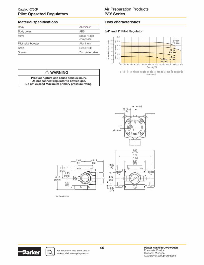
For inventory, lead time, and kit lookup, visit www.pdnplu.com
Parker Hannifi n CorporationPneumatic DivisionRichland, Michiganwww.parker.com/pneumatics
95
Material specifi cations
Body Aluminium
Body cover ABS
Valve Brass / NBR
composite
Pilot valve booster Aluminum
Seals Nitrile NBR
Screws Zinc plated steel
Flow characteristics
2.5 bar
36.3 psig
8.0 bar
116 psig
4.0 bar
58 psig
6.3 bar
91.4 psig
0 20 40 60 80 100 120 140 160 180 200 220 240 260 320 340280 300
0Flow - (scfm)
40 80 120 160 200 240 280 320 360 400 440 480 520 560 600 640 680 720
Sec
onda
ry P
ress
ure
- (b
ar)
0
120
100
80
60
40
20
0
9.0
7.5
6.0
4.5
3.0
1.5Sec
onda
ry P
ress
ure
- (p
sig)
Flow - (dm3/s)
n
3/4" and 1" Pilot Regulator
Catalog 0760P
Pilot Operated Regulators
Air Preparation ProductsP3Y Series
3.54(170)5.52(140)3.54(90)
1/8
0.35(9)
0.39(10)
1.93(49)
1.95(49.5)
2.22(56.5)
4.15(105.5)
1.97(50)
~3.11(79)
2.40(61)
0.75(19)
G1/8
pst
Inches (mm)
WARNING
Product rupture can cause serious injury.Do not connect regulator to bottled gas.
Do not exceed Maximum primary pressure rating.
!
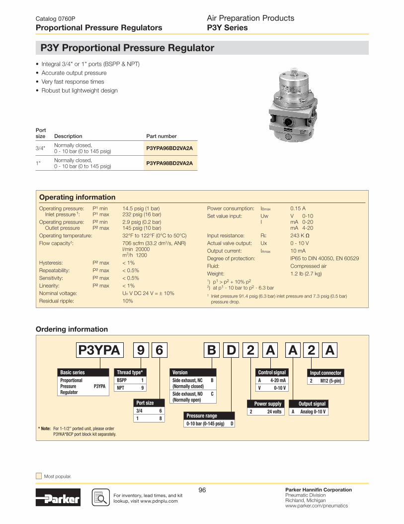
For inventory, lead times, and kit lookup, visit www.pdnplu.com
Parker Hannifi n CorporationPneumatic DivisionRichland, Michiganwww.parker.com/pneumatics
96
• Integral 3/4" or 1" ports (BSPP & NPT)
• Accurate output pressure
• Very fast response times
• Robust but lightweight design
Ordering information
Thread type*
BSPP 1
NPT 9
Version
Side exhaust, NC
(Normally closed)
B
Side exhaust, NO
(Normally open)
C
Port size
3/4 6
1 8
Control signal
A 4-20 mA
V 0-10 V
Pressure range
0-10 bar (0-145 psig) D
Output signal
A Analog 0-10 V
Power supply
2 24 volts
Input connector
2 M12 (5-pin)
Basic series
Proportional
Pressure
Regulator
P3YPA
P3YPA 9 6 B D 2 A A 2 A
* Note: For 1-1/2" ported unit, please orderP3YKA*BCP port block kit separately.
Catalog 0760P
Proportional Pressure Regulators
Air Preparation ProductsP3Y Series
P3Y Proportional Pressure Regulator
Portsize Description Part number
3/4"Normally closed,
0 - 10 bar (0 to 145 psig) P3YPA96BD2VA2A
1"Normally closed,
0 - 10 bar (0 to 145 psig) P3YPA98BD2VA2A
Operating information
Operating pressure: P1 min 14.5 psig (1 bar)
Inlet pressure 1: P1 max 232 psig (16 bar)
Operating pressure: P2 min 2.9 psig (0.2 bar)
Outlet pressure P2 max 145 psig (10 bar)
Operating temperature: 32°F to 122°F (0°C to 50°C)
Flow capacity†: 706 scfm (33.2 dm3/s, ANR)
l/min 20000
m3/h 1200
Hysteresis: P2 max < 1%
Repeatability: P2 max < 0.5%
Sensitivity: P2 max < 0.5%
Linearity: P2 max < 1%
Nominal voltage: Un V DC 24 V = 10%
Residual ripple: 10%
Power consumption: IBmax 0.15 A
Set value input: Uw V 0-10
I mA 0-20
mA 4-20
Input resistance: RE 243 K ΩActual valve output: Ux 0 - 10 V
Output current: IAmax 10 mA
Degree of protection: IP65 to DIN 40050, EN 60529
Fluid: Compressed air
Weight: 1.2 lb (2.7 kg)
1) p1 > p2 + 10% p2
2) at p1 - 10 bar to p2 - 6.3 bar
† Inlet pressure 91.4 psig (6.3 bar) inlet pressure and 7.3 psig (0.5 bar)
pressure drop.
Most popular.

For inventory, lead time, and kit lookup, visit www.pdnplu.com
Parker Hannifi n CorporationPneumatic DivisionRichland, Michiganwww.parker.com/pneumatics
97
* Two opposite gauge ports 1/4, plug screw mounted
** Connection for 5-pin plug M12 x 1
1
2
4
5
3
20000
1
2
3
4
5
6
7
8
4000 6000 8000 10000
8 2
8 4
8 6.310 6.3
12000 14000 16000 18000Q (l/min)
P2
(bar
)
Connection diagram
Material specifi cations
Housing Aluminium
Pilot valve booster Brass / NBR
composite aluminium
Standard seals NBR
Body cover screws Steel / zinc plated
Flow characteristics
Connector M12 x 1
Pin No. Function
1 24 V Supply
2 0 V Reference & mass capacity
3 0 - 10 V Set value input
4 0 V Signal
5 0 - 10 V Analog output
Cables
Type Part number
M12, 5-pin female to fl ying lead cable,
TPE; 2m (6.6 ft) RKC 4.5T-2/S1587
Catalog 0760P
Proportional Pressure Regulators
Air Preparation ProductsP3Y Series
Secondary pressure relief 1/8Exhaust pilot air M5
170(3.54)
140(5.52)
140(5.52)
90(3.54)
94(3.70)
G1(3/4)
9(.35)
10(.39)
40(1.57)
49(1.93)
50(1.97)
52(2.05)
61(2.40)
2.5(.10)
Max. 14 (.67)
Ø 64(Ø 2.52)
M12x1
*
**

For inventory, lead times, and kit lookup, visit www.pdnplu.com
Parker Hannifi n CorporationPneumatic DivisionRichland, Michiganwww.parker.com/pneumatics
98
• Integral 3/4" or 1" ports (BSPP or NPT)
• High effi ciency element as standard
• Excellent water removal effi ciency
• Robust but lightweight aluminium construction
• Secondary pressure ranges 12 and 16 bar
• Rolling diaphragm for extended life
• Secondary aspiration plus balanced poppet provides quick
response and accurate pressure regulation.
• Reverse fl ow / relieving option
• Low temperature -40°C (-40°F) with combined manual /
semi-auto drain as standard
1 21 2
Ordering information
Thread type*
BSPP 1
NPT 9
Port size
3/4 6
1 8
Adjustment range
E0 to 174 psi
(0 to 12 bar), no gauge
H0 to 232 psi
(0 to 16 bar), no gauge
F0 to 174 psi
(0 to 12 bar), gauge
J0 to 232 psi
(0 to 16 bar), gauge
Relief
B Relieving
RReverse fl ow /
relieving
Lockable
N Standard
A † Lockable
Basic series
Filter / Regulator P3YEA
Element
E 5 micron
Drain type
SCCombined manual
/ semi-auto drain
SA Auto drain
Notes:
* For 1-1/2" ported unit, please order P3YKA*BCP port block kit separately. † Not field convertible.
P3YEA 9 6 E SA B N E N
P3Y Filter / Regulator
Catalog 0760P
Filter / Regulators
Air Preparation ProductsP3Y Series
Portsize
Description (0 to 174 psi) Part number
3/4"Relieving, combined manual /semi-auto drain
P3YEA96ESCBNEN
3/4" Relieving, auto drain P3YEA96ESABNEN
3/4"Relieving, gauge, combined manual / semi-auto drain
P3YEA96ESCBNFN
3/4" Relieving, gauge, auto drain P3YEA96ESABNFN
1"Relieving, combined manual /semi-auto drain
P3YEA98ESCBNEN
1" Relieving, auto drain P3YEA98ESABNEN
1"Relieving, gauge, combined manual / semi-auto drain
P3YEA98ESCBNFN
1" Relieving, gauge, auto drain P3YEA98ESABNFN
Operating information
Supply pressure (max)*: 254 psig (17.5 bar)
Operating temperature:
Auto drain 14°F to 140°F (-10°C to 60°C)
Combined drain -40°F to 140°F (-40°C to 60°C)
Standard fi ltration: 5 micron
Manual / semi-auto drain: Closed at 11.6 psig (0.8 bar)
G1/8 thread male
Auto drain bowl pressure: Closed at 11.6 psig (0.8 bar)
Bowl capacity: 4.4 US oz. (130 cm3)
Standard fi ltration: 5 micron
Flow capacity†: 3/4" 335 scfm (158.1 dm3/s, ANR)
1" 465 scfm (219.5 dm3/s, ANR)
Fluid: Compressed air
Gauge port (x2): 1/4"
Weight: 3.3 lb (1.5 kg)
† Inlet pressure 91.4 psig (6.3 bar) inlet pressure and 7.3 psig (0.5 bar)
pressure drop.
* Air supply must be dry enough to avoid ice formation at temperatures
below 35.6°F (2°C).
Air quality:
Within ISO 8573-1: 1991 Class 3 and 5 (Particulates)
Within ISO 8573-1: 2001 Class 6 and 7 (Particulates)
Most popular.

For inventory, lead time, and kit lookup, visit www.pdnplu.com
Parker Hannifi n CorporationPneumatic DivisionRichland, Michiganwww.parker.com/pneumatics
99
(3/4") 5 Micron Filter / Regulator
(1") 5 Micron Filter / Regulator
Material specifi cations Body Aluminium
Sight glass and bowl Polypropylene
Body cover ABS
Element Sintered
polypropylene
Seals Nitrile NBR
Manual / semi-auto drain Acetal
Auto drain PA / Ø 10mm
brass connection
Bonnet Glass fi lled
polyamide
Control Knob Glass fi lled
polyamide
Valve Brass / NBR
Screws Steel / zinc
plated
Repair and Service Kits
5 micron element kit P3YKA00ESE
Bowl kit with combined manual/semi auto drain P3YKA00BSC
Bowl kit with auto drain P3YKA00BSA
Key lock kit P3XKA00AS
Diaphragm kit (relieving type) P3YKA00RR
Diaphragm kit (non-relieving type) P3YKA00RN
Angle bracket + metal lock ring P3YKA00MS
Panel mount nut P3YKA00MM
Flow characteristics
2.5 bar
36.3 psig
8.0 bar
116 psig
4.0 bar
58 psig
6.3 bar
91.4 psig
0 20 40 60 80 100 120 140 160 180 200 220 240 260 320280 300
0Flow - (scfm)
40 80 120 160 200 240 280 320 360 400 440 480 520 560 600 640 680
Sec
onda
ry P
ress
ure
- (b
ar)
0
120
100
80
60
40
20
0
9.0
7.5
6.0
4.5
3.0
1.5Sec
onda
ry P
ress
ure
- (p
sig)
Flow - (dm3/s)
n
Catalog 0760P
Filter / Regulators
Air Preparation ProductsP3Y Series
2.36(60)
2.74(69.5)
13.58(345)
8.45(212)
G1/8 male
5.24(133)
0.32(5)
0.35(9)
0.39(10)
2.17(55)
3.54(90)
2.40(61)
3.11(79)
M64x2
1.34(34)
Gauge port 1/4
Gauge port 1/4
Inches (mm)
Min. 3.15 (80mm) for filter changing
CAUTION:REGULATOR PRESSURE ADJUSTMENT – The working range of knob adjustment is designed to permit outlet pressures within their full range. Pressure adjustment beyond this range is also possible because the knob is not a limiting device. This is a common characteristic of most industrial regulators, and limiting devices may be obtained only by special design. For best performance, regulated pressure should always be set by increasing the pressure up to the desired setting.
WARNING
Product rupture can cause serious injury.Do not connect regulator to bottled gas.
Do not exceed Maximum primary pressure rating.
!

For inventory, lead times, and kit lookup, visit www.pdnplu.com
Parker Hannifi n CorporationPneumatic DivisionRichland, Michiganwww.parker.com/pneumatics
100
Lubricator
with drain
1 2
• Integral 3/4" or 1" ports (BSPP and NPT)
• Robust but lightweight aluminium construction
• Proportional oil delivery over a wide range of air fl ows
• Possible to fi ll under system pressure eliminating
down time
• Large oil reservoir
Ordering information
Thread type*
BSPP 1
NPT 9
Port size
3/4 6
1 8
Basic series
Lubricator P3YLA
P3YLA 9 6 LSNN
* Note: For 1-1/2" ported unit, please order P3YKA*BCP port block kit separately.
P3Y Lubricator
Catalog 0760P
Lubricators
Air Preparation ProductsP3Y Series
Portsize Description Part number
3/4" Oil mist, fi ll under pressure P3YLA96LSNN
1" Oil mist, fi ll under pressure P3YLA98LSNN
Operating information
Supply pressure (max)*: 254 psig (17.5 bar)
Operating temperature*: 14°F to 140°F (-10°C to 60°C)
Flow capacity†: 3/4" 315 scfm (148.2 dm3/s, ANR)
1" 390 scfm (184.1 dm3/s, ANR)
Fluid: Compressed air
Weight: 1.8 lb (0.8 kg)
† Inlet pressure 91.4 psig (6.3 bar) inlet pressure and 7.3 psig (0.5 bar)
pressure drop.
* Air supply must be dry enough to avoid ice formation at temperatures below
35.6°F (2°C).
Low fl ow start point (lubrication pick-up): at 6.3 bar (91.4 psig) inlet pressure
0.5 dm3/s (1.1 scfm).
Most popular.

For inventory, lead time, and kit lookup, visit www.pdnplu.com
Parker Hannifi n CorporationPneumatic DivisionRichland, Michiganwww.parker.com/pneumatics
101
(3/4") Lubricator
(1") Lubricator
Material specifi cations
Body Aluminium
Sight glass and bowl Polypropylene
Sight dome Polyamide
Lubricator cover ABS
Top & bottom end cap Glass fi lled nylon
Bayonet support Nylon
Seals Nitrile NBR
Repair and Service Kits
Bowl kit P3YKA00BSN
Refi ll plug P3YKA00PL
Oil (1 quart) F442001
Oil (1 galllon) F442002
Oil (12 quart case) F442003
Oil (4 gallon case) F442005
Flow characteristics
2.5
36.2
Primary Pressure - bar
Primary Pressure - psig
6.3
91.4
10
145
0 20 40 60 80 100 120 140 160 180 200 220 240 260 280 300
Pre
ssur
e D
rop
- (b
ar)
0
12
10
8
6
4
2
0
0.90
0.75
0.60
0.45
0.30
0.15
Pre
ssur
e D
rop
- (p
sig)
0Flow - (scfm)
100 200 300 400 500 600
Flow - (dm3/s)
n
2.5
36.2
Primary Pressure - bar
Primary Pressure - psig
6.3
91.4
10
145
0 20 40 60 80 100 120 140 160 180 200 220 240 260 280 300
Pre
ssur
e D
rop
- (b
ar)
0
12
10
8
6
4
2
0
0.90
0.75
0.60
0.45
0.30
0.15
Pre
ssur
e D
rop
- (p
sig)
0Flow - (scfm)
100 200 300 400 500 600
Flow - (dm3/s)
n
Catalog 0760P
Lubricators
Air Preparation ProductsP3Y Series
7.48(190)
9.72(247)
0.35(9)
.098(2.5) 0.39
(10)
1.97(55)
3.54(90)
1.57(47)
2.40(61)
1.85(40)
5.51(140)
6.69(170)
Inches (mm)

For inventory, lead times, and kit lookup, visit www.pdnplu.com
Parker Hannifi n CorporationPneumatic DivisionRichland, Michiganwww.parker.com/pneumatics
102
Port size
Flow‡
scfmWeightlb (kg)
Combined manual / semi-auto drain† Auto drain†
3/4" 170 7.3 (3.3) P3YCB96SECNFLNF P3YCB96SEANFLNF
1" 170 7.3 (3.3) P3YCB98SECNFLNF P3YCB98SEANFLNF
Port size
Flow‡
scfmWeightlb (kg)
Combined manual / semi-auto drain† Auto drain†
3/4" 315 6.2 (2.8) P3YCA96SECNFLNF P3YCA96SEANFLNF
1" 340 6.2 (2.8) P3YCA98SECNFLNF P3YCA98SEANFLNF
Ordering Information:
† Standard part numbers shown in bold. For other models refer to Options chart below.
‡ Flow with 10 bar (145 psig) inlet pressure, 6.3 bar (91.4 psig) set pressure and 1 bar (14.5 psig) pressure drop.
† Standard part numbers shown in bold. For other models refer to Options chart below.
‡ Flow with 10 bar (145 psig) inlet pressure, 6.3 bar (91.4 psig) set pressure and 1 bar (14.5 psig) pressure drop.
Filter + Regulator + Lubricator Combinations
5 micron element, 12 bar (174 psig) regulator + gauge and wall mounting bracket
Filter / Regulator + Lubricator Combinations
5 micron element, 12 bar (174 psig) regulator + gauge and wall mounting bracket
Thread type*
BSPP 1
NPT 9
Port size
3/4 6
1 8
Drain type
CCombined manual
/ semi-auto drain
A Auto drain
Adjustment range
F0-12 bar (0 to 174 psi)
with gauge
J0-16 bar (0 to 232 psi)
with gauge
Basic series
Filter / Regulator + Lubricator P3YCA
Filter + Regulator + Lubricator P3YCB
P3YCA 9 6 SE C N F LNF
* Note: For 1-1/2" ported unit, please order P3YKA*BCP port block kit separately.
Catalog 0760P
Combination Units
Air Preparation ProductsP3Y Series
P3Y Combinations
CAUTION:REGULATOR PRESSURE ADJUSTMENT –
The working range of knob adjustment is designed to permit outlet pressures
within their full range. Pressure adjustment beyond this range is also possible
because the knob is not a limiting device. This is a common characteristic of most
industrial regulators, and limiting devices may be obtained only by special design.
For best performance, regulated pressure should always be set by increasing the
pressure up to the desired setting.
Most popular.
WARNING
Product rupture can cause serious injury.Do not connect regulator to bottled gas.
Do not exceed Maximum primary pressure rating.
!

For inventory, lead time, and kit lookup, visit www.pdnplu.com
Parker Hannifi n CorporationPneumatic DivisionRichland, Michiganwww.parker.com/pneumatics
103
Catalog 0760P
Combination Units
Air Preparation ProductsP3Y Series
2.36(60)
2.74(69.5)
13.58(345)
8.45(212)
Gauge port 1/4
Gauge port 1/4
G1/8male
1.33(5.24)
0.32(5)
0.35(9)
0.39(10)
2.17(55)
10.63(270)3.54(90)
2.40(61)
3.11(79)
M64x2
1.34(34)
Min. 3.15 (80mm) for filter changing
2.36(60)
2.74(69.5)
13.58(345)
8.45(212)
G1/8 male
5.24(133)
0.32(5)
0.35(9)
0.39(10)
2.17(55)
7.09(180)
3.54(90)
2.40(61)
3.11(79)
M64x2
1.34(34)
Gauge port 1/4
Gauge port1/4
Min. 3.15 (80mm) for filter changing
8.45(212)
9.92(252)
1.57(40)
G1/8 male
0.35(9)
0.01(2.5)
2.40(61)
1.85(47)
1.97(50)
0.39(10)
3.54(90)
6.69(170)
5.51(140)
Min. 3.15 (80mm) for filter changing
P3Y Combinations

For inventory, lead times, and kit lookup, visit www.pdnplu.com
Parker Hannifi n CorporationPneumatic DivisionRichland, Michiganwww.parker.com/pneumatics
104
• Modular design with 3/4" & 1" integral ports
(BSPP or NPT)
• Provides for the safe introduction of pressure
• Automatically dumps downstream pressure on the
loss of pilot signal
• Adjustable slow start
• Solenoid or air pilot options
• High fl ow & exhaust capability
2
3 1
P3Y Series Combined Soft Start / Dump Valves, provide for
the safe introduction of pressure to machines or systems. Soft
Start / Dump Valves when set, allow the pressure to gradually
build to the set point before fully opening to deliver full fl ow at
line pressure.
The controlled introduction of pressure can be an important
safety factor and prevent damage to tooling when air pressure
is introduced at machine or system start up.
Ordering information
Thread type*
BSPP 1
NPT 9
Pilot type
External air pilot P
Solenoid pilot S
Actuator interface
30mm operator C
Threaded air pilot P
Port size
3/4 6
1 8
Solenoid type
A 30mm CNOMO coil
D 30mm CNOMO coil (M12 connection)
Solenoid voltage
2CN 24VDC
Basic series
Soft Start /
Dump ValveP3YTA
P3YTA 9 6 P C N A 2 C N
Solenoid type only
* Note: For 1-1/2" ported unit, please orderP3YKA*BCP port block kit separately.
Catalog 0760P
Soft Start / Dump Valve
Air Preparation ProductsP3Y Series
P3Y Combined Soft Start / Dump Valve
Portsize Description Part number
3/4" Air pilot operated P3YTA96PPN
3/4" 24VDC 30mm coil P3YTA96SCNA2CN
1" Air pilot operated P3YTA98PPN
1" 24VDC 30mm coil P3YTA98SCNA2CN
Operating information
Operating pressure (max):
30mm coil 232 psig (16 bar)
Operating pressure (min): 2.9 psig (0.2 bar)
Operating temperature*:
Solenoid operated 14°F to 140°F (-10°C to 60°C)
Air pilot operated 14°F to 140°F (-10°C to 60°C)
Air pilot port: 1/8"
Exhaust port: 1"
Gauge port: 1/4"
Flow capacity†: 3/4" 371 scfm (175.1 dm3/s, ANR)
1" 424 scfm (200.1 dm3/s, ANR)
Fluid: Compressed air
Weight: Air pilot 3.1 lb (1.4 kg)
30mm coil 3.5 lb (1.6 kg)
† Inlet pressure 91.4 psig (6.3 bar) inlet pressure and 7.3 psig (0.5 bar)
pressure drop.
* Air supply must be dry enough to avoid ice formation at temperatures
below 35.6°F (2°C).
Snap pressure: Full fl ow when downstream pressure reaches 50% of the
inlet pressure.
Most popular.

For inventory, lead time, and kit lookup, visit www.pdnplu.com
Parker Hannifi n CorporationPneumatic DivisionRichland, Michiganwww.parker.com/pneumatics
105
100%
90%
4
3
21
Time (t)
Pre
ssu
re (
p)
0%
Start signalSwitching time delayGradual pressure build upOperating pressure p2 (= p1)
1
2
3
4
Combined start / stop function
Combined start / stop function with acknowledgement
Note: For solenoid coil and cable plug options see solenoid operator pages.
Material specifi cations
Body Aluminium
Body cover ABS
Valve Brass / NBR
composite
Pilot valve booster Aluminum
Seals Nitrile NBR
Flow characteristics
Catalog 0760P
Soft Start / Dump Valve
Air Preparation ProductsP3Y Series
3.54(90)
3.50(89)
Ø 1.18(30)
3.70(94)
3/4(G1)
3/4(G1)
1/8
SW3
4.09(104)
1.93(49)
2.20(56)
0.59(15)
3.19(81)
0.6(15.25)
1A 12
23
0.63(16)
0.98(25)
0.98(25)
3.54(90)
3.50(89)
3.70(94)
3/4(G1)
G1(3/4)
SW3
4.09(104)
1.93(49)
2.20(56)
2.40(61)
0.67(17)
0.98(25)
0.98(25)
3.19(81)
0.6(15.25)
Inches (mm)

For inventory, lead times, and kit lookup, visit www.pdnplu.com
Parker Hannifi n CorporationPneumatic DivisionRichland, Michiganwww.parker.com/pneumatics
106
• Integral 3/4" or 1" ports
• Smooth start-up of pneumatic system
• Air pilot operation
• Adjustable slow start
• High fl ow
Ordering information
Thread type*
BSPP 1
NPT 9
Port size
3/4 6
1 8
Basic series
Soft Start Valve P3YSA
P3YSA 9 6 Y 0 N
* Note: For 1-1/2" ported unit, please orderP3YKA*BCP port block kit separately.
Material specifi cations
Body Aluminium
Body cover ABS
Valve Brass / NBR
composite
Pilot valve booster Aluminum
Seals Nitrile NBR
100%
90%
4
3
21
Time (t)
Pre
ssu
re (
p)
0%
Start signalSwitching time delayGradual pressure build upOperating pressure p2 (= p1)
1
2
3
4
Flow characteristics
Catalog 0760P
Soft Start Valve
Air Preparation ProductsP3Y Series
P3Y Soft Start Valve
Portsize Description Part number
3/4" Soft start valve P3YSA96Y0N
1" Soft start valve P3YSA98Y0N
Operating information
Operating pressure (max): 254 psig (17.5 bar)
Operating pressure (min): 29 psig (2 bar)
Operating temperature*:
Solenoid operated 14°F to 140°F (-10°C to 60°C)
Air pilot operated 14°F to 140°F (-10°C to 60°C)
Flow capacity†: 3/4" 324 scfm (152.9 dm3/s, ANR)
1" 324 scfm (152.9 dm3/s, ANR)
Fluid: Compressed air
Weight: 1.8 lb (0.8 kg)
† Inlet pressure 91.4 psig (6.3 bar) inlet pressure and 7.3 psig (0.5 bar)
pressure drop.
* Air supply must be dry enough to avoid ice formation at temperatures
below 35.6°F (2°C).
Snap pressure: Full fl ow when downstream pressure reaches 50% of the
inlet pressure.
3.54(90)
1.85(47) SW31.97
(50)
3/4(G1)
51(2.01)
34(1.34)
Inches (mm)
Most popular.

For inventory, lead time, and kit lookup, visit www.pdnplu.com
Parker Hannifi n CorporationPneumatic DivisionRichland, Michiganwww.parker.com/pneumatics
107
P3Y Modular Ball Valve
Operating information
Operating pressure (max): 254 psig (17.5 bar)
Operating pressure (min): 29 psig (2 bar)
Operating temperature: 14°F to 140°F (-10°C to 60°C)
Flow capacity†: 3/4" 705.6 scfm (333 dm3/s, ANR)
1" 705.6 scfm (333 dm3/s, ANR)
Weight: 3/4" 2.4 lb (1.1 kg)
1" 2.4 lb (1.1 kg)
• Positive bubble tight shut-off
• 90° turn handle to prevent unauthorized adjustment
• Pad lockable (up to 6 times)
• When the inlet pressure is turned off the downstream vents
through the exhaust port
Ball / Lockout Valve shuts off downstream line pressure
in the closed position with a 90° turn of the handle. In the
closed position, inlet air pressure is blocked and downstream
/ system air is exhausted through a threaded port. To
prevent unauthorized adjustment, the padlock slide may be
assembled on either side. It is recommended that this slide is
installed after fi nal system assembly.
The Safety Lockout valves conform to OSHA #29 CFR part
1910 – control of hazardous energy source (lockout / tagout).
3.54(90)
0.35(9)
1/4NPT
3.54(90)
Ø 1.73(44)
Ø 2.74(69.5)
2.60(66)
5.31(135)
3.19(81) 2.34
(59.2)
2.60(66)
3.15(80)
3/4(G1)
0.40(10.2)
Inches (mm)
Material Specifi cations
Body Aluminium
Valve ball Brass / nickle
plated
Handle Aluminum
Seals Nitrile NBR
Exhaust silencer Sintered
bronze
Ordering information
Thread type*
BSPP 1
NPT 9
Port size
3/4 6
1 8
Basic series
Modular Ball Valve P3YVA
P3YVA 9 6 LBN
* Note: For 1-1/2" ported unit, please order P3YKA*BCP port block kit separately.
Catalog 0760P
Modular Ball Valve
Air Preparation ProductsP3Y Series
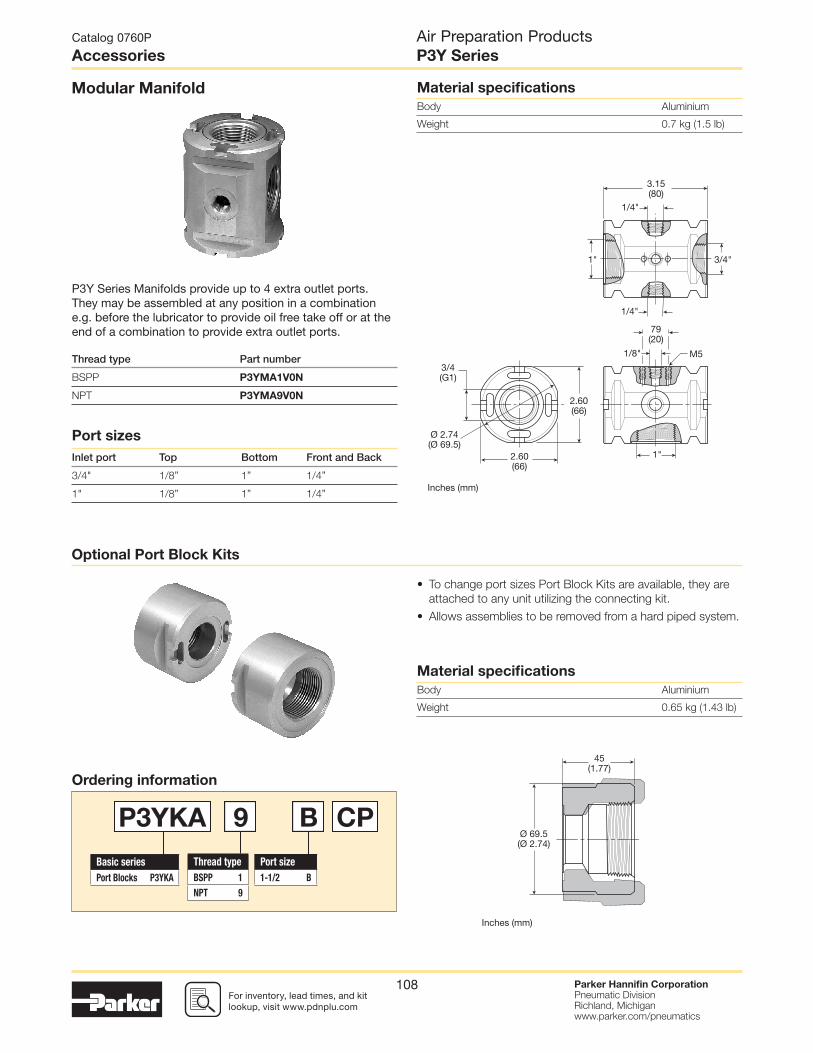
For inventory, lead times, and kit lookup, visit www.pdnplu.com
Parker Hannifi n CorporationPneumatic DivisionRichland, Michiganwww.parker.com/pneumatics
108
Optional Port Block Kits
• To change port sizes Port Block Kits are available, they are
attached to any unit utilizing the connecting kit.
• Allows assemblies to be removed from a hard piped system.
Modular Manifold
P3Y Series Manifolds provide up to 4 extra outlet ports. They may be assembled at any position in a combination e.g. before the lubricator to provide oil free take off or at the end of a combination to provide extra outlet ports.
Thread type Part number
BSPP P3YMA1V0N
NPT P3YMA9V0N
Port sizes
Inlet port Top Bottom Front and Back
3/4" 1/8” 1” 1/4”
1" 1/8” 1” 1/4”
Ordering information
Material specifi cations
Body Aluminium
Weight 0.65 kg (1.43 lb)
Material specifi cations
Body Aluminium
Weight 0.7 kg (1.5 lb)
Thread type
BSPP 1
NPT 9
Port size
1-1/2 B
Basic series
Port Blocks P3YKA
P3YKA 9 B CP
Catalog 0760P
Accessories
Air Preparation ProductsP3Y Series
3.15(80)
Ø 2.74(Ø 69.5)
3/4"
1/4"
1"
2.60(66)
2.60(66)
3/4(G1)
1"
1/4"
1/8" M5
79(20)
Inches (mm)
Ø 69.5(Ø 2.74)
45(1.77)
Inches (mm)

For inventory, lead time, and kit lookup, visit www.pdnplu.com
Parker Hannifi n CorporationPneumatic DivisionRichland, Michiganwww.parker.com/pneumatics
109
Catalog 0760P
Accessories
Air Preparation ProductsP3Y Series
Solenoid Operators - CNOMO
Materials
Technical data -
Solenoid operators, coil combinations
Pilot Valve
Body: Polyamide
Armature tube: Brass
Plunger & core: Corrosion resistant Cr-Ni steel
Seals: Fluorocarbon
Screws: Stainless steel
Coil
Encapsulation material: Thermoplastic as standard
Duroplast for M12 connection
Transients
Interrupting the current through the solenoid coil produces
momentary voltage peaks which, under unfavorable
conditions, can amount to several hundred times the rated
operating voltage. Normally, these transients do not cause
problems, but to achieve the Maximum life of relays in the
circuit (and particularly of transistors, thyristors and integrated
circuits) it is desirable to provide protection by means of
voltage-dependent resistors (varistors). All connectors/cable
plugs EN175301-803 with LED’s include this type of circuit
protection.
Solenoid Coils with M12 Connection
Solenoid Coils with DIN A or Industrial B Connection
Note: Solenoid pilot operators are fi tted to the Global range. Order the
above part numbers for spares. The operators are supplied with
mounting screws and interface ‘O’ rings. Coils and connectors must
be ordered separately.
Voltage
22mm x 30mmPart number B industrial standard
Weight(Kg)
30mm x 30mmPart numberDIN 43650Astandard
Weight(Kg)
Direct current
24VDC P2FCB449 0.093 P2FCA449 0.105
Alternative current
110V 50Hz, 120V 60Hz P2FCB453 0.093 P2FCA453 0.105
Voltage Part numberWeight(Kg)
Direct current
24VDC P2FC6449 0.065
Spare Base Solenoid Pilot OperatorCNOMO NC
Description Part number Weight(Kg)
Non-lock
Manual Override P2FP23N4B 0.065
No Override P2FP23N4A 0.065
NC Normal Operatorwith 22 x 30
standard coil
NC Normal Operatorwith 30 x 30
standard coil
Working pressure 0 to 10 bar 0 to 10 bar
Ambient
temperature-10°C to 60°C * -10°C to 60°C *
Power (DC) 4.8W 2.7W
Power (AC) 8.5VA 4.9VA
Voltage tolerance +/-10% +/-10%
Duty cycle 100% 100%
Insulation class F F
Electric connection B Industrial DIN 43650A
Protection IP65 IP65
Approval UL/CSA
Working media All neutral media such as compressed air
* Limited to 50°C if use with 100% duty cycle
Most popular.

For inventory, lead times, and kit lookup, visit www.pdnplu.com
Parker Hannifi n CorporationPneumatic DivisionRichland, Michiganwww.parker.com/pneumatics
110
PS2429BP PS2028BP
PS243079BP PS203279BP
PS2430J79BP PS2032J79CP
PS243083BP PS203283BP
PS2430J83BP PS2032J83CP
PS294679BP PS294683BP
PS2946J79BP PS2946J83BP
Solenoid Connectors / Cable Plugs EN175301-803
Description
Part number22mm Form B
Industrial
Part number30mm Form A
DIN 43650A
With standard screw Standard IP65 without fl ying lead PS2429BP PS2028BP
With LED and protection 24VAC/DC PS243079BP PS203279BP
With LED and protection 110VAC PS243083BP PS203283BP
With cable Standard with 2m cable IP65 PS2429JBP PS2028JCP
24VAC/DC, 2m cable LED and protection IP65 PS2430J79BP PS2032J79CP
110VAC/DC, 2m cable LED and protection IP65 PS2430J83BP PS2032J83CP
Solenoid coil dimensions mm (inches)
Cable plug dimensions mm (inches)
Electrical schematics
22mm Form B industrial cable plugs
22 x 30mm 30 x 30mm
30mm DIN 43650A cable plugs
Catalog 0760P
Accessories
Air Preparation ProductsP3Y Series
1.26(32)
1.22(31)
1.22(31)
1.65(42)1.87
(47.5)
0.50(5)
M3
1.18(30)
1.22(31)
1.57(40)
0.82(20.8)
0.22(5.5)
1.18(30)
1.18(30)
1.77(45)
1.61(41)
1.22(31)
1.30(33)
0.87(22)
2.36(60)
2.01(51)
0.86(22)
1.89(48)
1.42(36)
1.18(30)
1.22(31)
0.87(22)
2.36(60)
2.05(52)
Most popular.

For inventory, lead time, and kit lookup, visit www.pdnplu.com
Parker Hannifi n CorporationPneumatic DivisionRichland, Michiganwww.parker.com/pneumatics
111
Description ConnectionWeightlb (kg) Part number
0.01 micron element kit P3YKA00ESC
5 micron element kit P3YKA00ESE
Adsorber element kit P3YKA00ESA
Angle bracket + metal lock ring P3YKA00MS
Bowl kit with combined manual / semi-auto drain P3YKA00BSC
Bowl kit with auto drain P3YKA00BSA
Bowl kit P3YKA00BSN
Connector o-ring kit Qty: 5 P3YKA08CY
Differential pressure indicator kit P3YKA00RQ
Diaphragm kit (relieving type) P3YKA00RR
Diaphragm kit (non-relieving type) P3YKA00RN
Key lock (replacement) P3XKA00AS
Lubricator oil
F442001 - 1 Qt.2.03
(0.92)
F442001
F442002 - 1 Gal F442002
Neck mounting bracket kit8.27
(3.75) P3YKA00MS
P3Y connecting kit0.11
(0.05) P3YKA00CB
Panel mounting nut (Aluminium)1.54
(0.70) P3YKA00MM
Pressure gauge
0 to 160 psig(0 to 10 bar)
1/4”0.13
(0.06) K4520N14160
0 to 300 psig(0 to 20 bar)
1/4”0.13
(0.06) K4520N14300
Refi ll plug P3YKA00PL
Wall mounting brackets0.44(0.2)
P3YKA00CW
Accessories
Catalog 0760P
Accessories
Air Preparation ProductsP3Y Series
Most popular.

For inventory, lead times, and kit lookup, visit www.pdnplu.com
Parker Hannifi n CorporationPneumatic DivisionRichland, Michiganwww.parker.com/pneumatics
112
Air Preparation ProductsCatalog 0760P
Parker Pneumatic

For inventory, lead time, and kit lookup, visit www.pdnplu.com
Parker Hannifi n CorporationPneumatic DivisionRichland, Michiganwww.parker.com/pneumatics
113
Air Preparation ProductsSafety Guide
Catalog 0760P
Parker Pneumatic
Safety Guide For Selecting And Using Pneumatic Division
Products And Related AccessoriesWARNING:
FAILURE OR IMPROPER SELECTION OR IMPROPER USE OF PNEUMATIC DIVISION PRODUCTS, ASSEMBLIES
OR RELATED ITEMS (“PRODUCTS”) CAN CAUSE DEATH, PERSONAL INJURY, AND PROPERTY DAMAGE.
POSSIBLE CONSEQUENCES OF FAILURE OR IMPROPER SELECTION OR IMPROPER USE OF THESE
PRODUCTS INCLUDE BUT ARE NOT LIMITED TO:
• Unintended or mistimed cycling or motion of machine members or failure to cycle
• Work pieces or component parts being thrown off at high speeds.
• Failure of a device to function properly for example, failure to clamp or unclamp an associated item or device.
• Explosion
• Suddenly moving or falling objects.
• Release of toxic or otherwise injurious liquids or gasses.
Before selecting or using any of these Products, it is important that you read and follow the instructions below.
!
1. GENERAL INSTRUCTIONS
1.1. Scope: This safety guide is designed to cover general guidelines on the installation, use, and maintenance of Pneumatic Division
Valves, FRLs (Filters, Pressure Regulators, and Lubricators), Vacuum products and related accessory components.
1.2. Fail-Safe: Valves, FRLs, Vacuum products and their related components can and do fail without warning for many reasons. Design all
systems and equipment in a fail-safe mode, so that failure of associated valves, FRLs or Vacuum products will not endanger persons
or property.
1.3 Relevant International Standards: For a good guide to the application of a broad spectrum of pneumatic fl uid power devices see:
ISO 4414:1998, Pneumatic Fluid Power – General Rules Relating to Systems. See www.iso.org for ordering information.
1.4. Distribution: Provide a copy of this safety guide to each person that is responsible for selection, installation, or use of Valves, FRLs
or Vacuum products. Do not select, or use Parker valves, FRLs or vacuum products without thoroughly reading and understanding this
safety guide as well as the specifi c Parker publications for the products considered or selected.
1.5. User Responsibility: Due to the wide variety of operating conditions and applications for valves, FRLs, and vacuum products Parker
and its distributors do not represent or warrant that any particular valve, FRL or vacuum product is suitable for any specifi c end use
system. This safety guide does not analyze all technical parameters that must be considered in selecting a product. The user, through
its own analysis and testing, is solely responsible for:
• Making the fi nal selection of the appropriate valve, FRL, Vacuum component, or accessory.
• Assuring that all user’s performance, endurance, maintenance, safety, and warning requirements are met and that the application
presents no health or safety hazards.
• Complying with all existing warning labels and / or providing all appropriate health and safety warnings on the equipment on which
the valves, FRLs or Vacuum products are used; and,
• Assuring compliance with all applicable government and industry standards.
1.6. Safety Devices: Safety devices should not be removed, or defeated.
1.7. Warning Labels: Warning labels should not be removed, painted over or otherwise obscured.
1.8. Additional Questions: Call the appropriate Parker technical service department if you have any questions or require any additional
information. See the Parker publication for the product being considered or used, or call 1-800-CPARKER, or go to www.parker.com,
for telephone numbers of the appropriate technical service department.
2. PRODUCT SELECTION INSTRUCTIONS
2.1. Flow Rate: The fl ow rate requirements of a system are frequently the primary consideration when designing any pneumatic system.
System components need to be able to provide adequate fl ow and pressure for the desired application.
2.2. Pressure Rating: Never exceed the rated pressure of a product. Consult product labeling, Pneumatic Division catalogs or the
instruction sheets supplied for maximum pressure ratings.
2.3. Temperature Rating: Never exceed the temperature rating of a product. Excessive heat can shorten the life expectancy of a product
and result in complete product failure.
2.4. Environment: Many environmental conditions can affect the integrity and suitability of a product for a given application. Pneumatic
Division products are designed for use in general purpose industrial applications. If these products are to be used in unusual
circumstances such as direct sunlight and/or corrosive or caustic environments, such use can shorten the useful life and lead to
premature failure of a product.
2.5. Lubrication and Compressor Carryover: Some modern synthetic oils can and will attack nitrile seals. If there is any possibility of
synthetic oils or greases migrating into the pneumatic components check for compatibility with the seal materials used. Consult the
factory or product literature for materials of construction.
2.6. Polycarbonate Bowls and Sight Glasses: To avoid potential polycarbonate bowl failures:
• Do not locate polycarbonate bowls or sight glasses in areas where they could be subject to direct sunlight, impact blow, or
temperatures outside of the rated range.
• Do not expose or clean polycarbonate bowls with detergents, chlorinated hydro-carbons, keytones, esters or certain alcohols.
• Do not use polycarbonate bowls or sight glasses in air systems where compressors are lubricated with fi re resistant fl uids such as
phosphate ester and di-ester lubricants.

For inventory, lead times, and kit lookup, visit www.pdnplu.com
Parker Hannifi n CorporationPneumatic DivisionRichland, Michiganwww.parker.com/pneumatics
114
Air Preparation ProductsSafety Guide
Catalog 0760P
Parker Pneumatic
2.7. Chemical Compatibility: For more information on plastic component chemical compatibility see Pneumatic Division technical bulletins
Tec-3, Tec-4, and Tec-5
2.8. Product Rupture: Product rupture can cause death, serious personal injury, and property damage.
• Do not connect pressure regulators or other Pneumatic Division products to bottled gas cylinders.
• Do not exceed the maximum primary pressure rating of any pressure regulator or any system component.
• Consult product labeling or product literature for pressure rating limitations.
3. PRODUCT ASSEMBLY AND INSTALLATION INSTRUCTIONS
3.1. Component Inspection: Prior to assembly or installation a careful examination of the valves, FRLs or vacuum products must be
performed. All components must be checked for correct style, size, and catalog number. DO NOT use any component that displays any
signs of nonconformance.
3.2. Installation Instructions: Parker published Installation Instructions must be followed for installation of Parker valves, FRLs and
vacuum components. These instructions are provided with every Parker valve or FRL sold, or by calling 1-800-CPARKER, or at
www.parker.com.
3.3. Air Supply: The air supply or control medium supplied to Valves, FRLs and Vacuum components must be moisture-free if ambient
temperature can drop below freezing
4. VALVE AND FRL MAINTENANCE AND REPLACEMENT INSTRUCTIONS
4.1. Maintenance: Even with proper selection and installation, valve, FRL and vacuum products service life may be signifi cantly reduced
without a continuing maintenance program. The severity of the application, risk potential from a component failure, and experience
with any known failures in the application or in similar applications should determine the frequency of inspections and the servicing or
replacement of Pneumatic Division products so that products are replaced before any failure occurs. A maintenance program must
be established and followed by the user and, at minimum, must include instructions 4.2 through 4.9.
4.2. Installation and Service Instructions: Before attempting to service or replace any worn or damaged parts consult the appropriate
Service Bulletin for the valve or FRL in question for the appropriate practices to service the unit in question. These Service and
Installation Instructions are provided with every Parker valve and FRL sold, or are available by calling 1-800-CPARKER, or by accessing
the Parker web site at www.parker.com.
4.3. Lockout / Tagout Procedures: Be sure to follow all required lockout and tagout procedures when servicing equipment. For more
information see: OSHA Standard – 29 CFR, Part 1910.147, Appendix A, The Control of Hazardous Energy – (Lockout / Tagout)
4.4. Visual Inspection: Any of the following conditions requires immediate system shut down and replacement of worn or damaged
components:
• Air leakage: Look and listen to see if there are any signs of visual damage to any of the components in the system. Leakage is an
indication of worn or damaged components.
• Damaged or degraded components: Look to see if there are any visible signs of wear or component degradation.
• Kinked, crushed, or damaged hoses. Kinked hoses can result in restricted air fl ow and lead to unpredictable system behavior.
• Any observed improper system or component function: Immediately shut down the system and correct malfunction.
• Excessive dirt build-up: Dirt and clutter can mask potentially hazardous situations.
Caution: Leak detection solutions should be rinsed off after use.
4.5. Routine Maintenance Issues:
• Remove excessive dirt, grime and clutter from work areas.
• Make sure all required guards and shields are in place.
4.6. Functional Test: Before initiating automatic operation, operate the system manually to make sure all required functions operate
properly and safely.
4.7. Service or Replacement Intervals: It is the user’s responsibility to establish appropriate service intervals. Valves, FRLs and vacuum
products contain components that age, harden, wear, and otherwise deteriorate over time. Environmental conditions can signifi cantly
accelerate this process. Valves, FRLs and vacuum components need to be serviced or replaced on routine intervals. Service intervals
need to be established based on:
• Previous performance experiences.
• Government and / or industrial standards.
• When failures could result in unacceptable down time, equipment damage or personal injury risk.
4.8. Servicing or Replacing of any Worn or Damaged Parts: To avoid unpredictable system behavior that can cause death, personal
injury and property damage:
• Follow all government, state and local safety and servicing practices prior to service including but not limited to all OSHA Lockout
Tagout procedures (OSHA Standard – 29 CFR, Part 1910.147, Appendix A, The Control of Hazardous Energy – Lockout / Tagout).
• Disconnect electrical supply (when necessary) before installation, servicing, or conversion.
• Disconnect air supply and depressurize all air lines connected to system and Pneumatic Division products before installation, service,
or conversion.
• Installation, servicing, and / or conversion of these products must be performed by knowledgeable personnel who understand how
pneumatic products are to be applied.
• After installation, servicing, or conversions air and electrical supplies (when necessary) should be connected and the product tested
for proper function and leakage. If audible leakage is present, or if the product does not operate properly, do not put product or
system into use.
• Warnings and specifi cations on the product should not be covered or painted over. If masking is not possible, contact your local
representative for replacement labels.
4.9. Putting Serviced System Back into Operation: Follow the guidelines above and all relevant Installation and Maintenance Instructions
supplied with the valve FRL or vacuum component to insure proper function of the system.

For inventory, lead time, and kit lookup, visit www.pdnplu.com
Parker Hannifi n CorporationPneumatic DivisionRichland, Michiganwww.parker.com/pneumatics
115
1. Terms and Conditions. Seller’s willingness to offer Products for sale or accept an
order for Products is subject to the terms and conditions contained in this Offer of Sale
or any newer version of the same, published by Seller electronically at www.parker.com/
saleterms/. Seller objects to any contrary or additional terms or conditions of Buyer’s
order or any other document or other communication issued by Buyer.
2. Price; Payment. Prices stated on Seller’s Quote are valid for thirty (30) days, except
as explicitly otherwise stated therein, and do not include any sales, use, or other taxes or
duties unless specifi cally stated. Seller reserves the right to modify prices to adjust for any
raw material price fl uctuations. Unless otherwise specifi ed by Seller, all prices are F.C.A.
Seller’s facility (INCOTERMS 2010). Payment is subject to credit approval and payment
for all purchases is due thirty (30) days from the date of invoice (or such date as may be
specifi ed by Seller’s Credit Department). Unpaid invoices beyond the specifi ed payment
date incur interest at the rate of 1.5% per month or the maximum allowable rate under
applicable law.
3. Shipment; Delivery; Title and Risk of Loss. All delivery dates are approximate.
Seller is not responsible for damages resulting from any delay. Regardless of the manner
of shipment, delivery occurs and title and risk of loss or damage pass to Buyer, upon
placement of the Products with the shipment carrier at Seller’s facility. Unless otherwise
stated, Seller may exercise its judgment in choosing the carrier and means of delivery. No
deferment of shipment at Buyers’ request beyond the respective dates indicated will be
made except on terms that will indemnify, defend and hold Seller harmless against all loss
and additional expense. Buyer shall be responsible for any additional shipping charges
incurred by Seller due to Buyer’s acts or omissions.
4. Warranty. Seller warrants that the Products sold hereunder shall be free
from defects in material or workmanship for a period of twelve (12) months from
the date of delivery or 2,000 hours of normal use, whichever occurs fi rst. All
prices are based upon the exclusive limited warranty stated above, and upon
the following disclaimer: DISCLAIMER OF WARRANTY: THIS WARRANTY IS
THE SOLE AND ENTIRE WARRANTY PERTAINING TO PRODUCTS PROVIDED.
SELLER DISCLAIMS ALL OTHER WARRANTIES, EXPRESS AND IMPLIED,
INCLUDING DESIGN, MERCHANTABILITY AND FITNESS FOR A PARTICULAR
PURPOSE.
5. Claims; Commencement of Actions. Buyer shall promptly inspect all Products
upon receipt. No claims for shortages will be allowed unless reported to the Seller within
ten (10) days of delivery. No other claims against Seller will be allowed unless asserted
in writing within thirty (30) days after delivery. Buyer shall notify Seller of any alleged
breach of warranty within thirty (30) days after the date the defect is or should have been
discovered by Buyer. Any claim or action against Seller based upon breach of contract
or any other theory, including tort, negligence, or otherwise must be commenced within
twelve (12) months from the date of the alleged breach or other alleged event, without
regard to the date of discovery.
6. LIMITATION OF LIABILITY. IN THE EVENT OF A BREACH OF WARRANTY,
SELLER WILL, AT ITS OPTION, REPAIR OR REPLACE A DEFECTIVE PRODUCT, OR
REFUND THE PURCHASE PRICE WITHIN A REASONABLE PERIOD OF TIME. IN
NO EVENT IS SELLER LIABLE FOR ANY SPECIAL, INDIRECT, INCIDENTAL OR
CONSEQUENTIAL DAMAGES ARISING OUT OF, OR AS THE RESULT OF, THE
SALE, DELIVERY, NON-DELIVERY, SERVICING, USE OR LOSS OF USE OF THE
PRODUCTS OR ANY PART THEREOF, OR FOR ANY CHARGES OR EXPENSES OF
ANY NATURE INCURRED WITHOUT SELLER’S WRITTEN CONSENT, WHETHER
BASED IN CONTRACT, TORT OR OTHER LEGAL THEORY. IN NO EVENT SHALL
SELLER’S LIABILITY UNDER ANY CLAIM MADE BY BUYER EXCEED THE
PURCHASE PRICE OF THE PRODUCTS.
7. User Responsibility. The user, through its own analysis and testing, is solely
responsible for making the fi nal selection of the system and Product and assuring that
all performance, endurance, maintenance, safety and warning requirements of the
application are met. The user must analyze all aspects of the application and follow
applicable industry standards and Product information. If Seller provides Product or
system options based upon data or specifi cations provided by the user, the user is
responsible for determining that such data and specifi cations are suitable and suffi cient
for all applications and reasonably foreseeable uses of the Products or systems.
8. Loss to Buyer’s Property. Any designs, tools, patterns, materials, drawings,
confi dential information or equipment furnished by Buyer or any other items which become
Buyer’s property, will be considered obsolete and may be destroyed by Seller after two
(2) consecutive years have elapsed without Buyer ordering the items manufactured using
such property. Seller shall not be responsible for any loss or damage to such property
while it is in Seller’s possession or control.
9. Special Tooling. A tooling charge may be imposed for any special tooling, including
without limitation, dies, fi xtures, molds and patterns, acquired to manufacture Products.
Such special tooling shall be and remain Seller’s property notwithstanding payment of
any charges by Buyer. In no event will Buyer acquire any interest in apparatus belonging
to Seller which is utilized in the manufacture of the Products, even if such apparatus
has been specially converted or adapted for such manufacture and notwithstanding any
charges paid by Buyer. Unless otherwise agreed, Seller has the right to alter, discard or
otherwise dispose of any special tooling or other property in its sole discretion at any time.
10. Buyer’s Obligation; Rights of Seller. To secure payment of all sums due or
otherwise, Seller retains a security interest in all Products delivered to Buyer and this
agreement is deemed to be a Security Agreement under the Uniform Commercial Code.
Buyer authorizes Seller as its attorney to execute and fi le on Buyer’s behalf all documents
Seller deems necessary to perfect its security interest.
11. Improper Use and Indemnity. Buyer shall indemnify, defend, and hold Seller
harmless from any losses, claims, liabilities, damages, lawsuits, judgments and costs
The goods, services or work (referred to as the “Products”) offered by Parker-Hannifi n Corporation, its subsidiaries, groups, divisions, and authorized distributors (“Seller”) are offered for sale at prices indicated in the offer, or as may be established by Seller. The offer to sell the Products and acceptance of Seller’s offer by any customer (“Buyer”) is contingent upon, and will be governed by all of the terms and conditions contained in this Offer of Sale. Buyer’s order for any Products specifi ed in Buyer’s purchase document or Seller’s offer, proposal or quote (“Quote”) attached to the purchase order, when communicated to Seller verbally, or in writing, shall constitute acceptance of this offer.
(including attorney fees and defense costs), whether for personal injury, property damage,
patent, trademark or copyright infringement or any other claim, brought by or incurred
by Buyer, Buyer’s employees, or any other person, arising out of: (a) improper selection,
application, design, specifi cation or other misuse of Products purchased by Buyer from
Seller; (b) any act or omission, negligent or otherwise, of Buyer; (c) Seller’s use of patterns,
plans, drawings, or specifi cations furnished by Buyer to manufacture Products; or (d)
Buyer’s failure to comply with these terms and conditions. Seller shall not indemnify Buyer
under any circumstance except as otherwise provided.
12. Cancellations and Changes. Buyer may not cancel or modify or cancel any order
for any reason, except with Seller’s written consent and upon terms that will indemnify,
defend and hold Seller harmless against all direct, incidental and consequential loss or
damage. Seller may change Product features, specifi cations, designs and availability.
13. Limitation on Assignment. Buyer may not assign its rights or obligations under this
agreement without the prior written consent of Seller.
14. Force Majeure. Seller does not assume the risk and is not liable for delay or failure
to perform any of Seller’s obligations by reason of events or circumstances beyond its
reasonable control (hereinafter “Events of Force Majeure”). Events of Force Majeure shall
include without limitation: accidents, strikes or labor disputes, acts of any government or
government agency, acts of nature, delays or failures in delivery from carriers or suppliers,
shortages of materials, or any other cause beyond Seller’s reasonable control.
15. Waiver a n d Severability. Failure to enforce any provision of this agreement will not
invalidate that provision; nor will any such failure prejudice Seller’s right to enforce that
provision in the future. Invalidation of any provision of this agreement by legislation or
other rule of law shall not invalidate any other provision herein. The remaining provisions
of this agreement will remain in full force and effect.
16. Termination. Seller may terminate this agreement for any reason and at any time
by giving Buyer thirty (30) days prior written notice. Seller may immediately terminate this
agreement, in writing, if Buyer: (a) breaches any provision of this agreement (b) appoints
a trustee, receiver or custodian for all or any part of Buyer’s property (c) fi les a petition
for relief in bankruptcy on its own behalf, or one if fi led by a third party (d) makes an
assignment for the benefi t of creditors; or (e) dissolves its business or liquidates all or a
majority of its assets.
17. Governing Law. This agreement and the sale and delivery of all Products are
deemed to have taken place in, and shall be governed and construed in accordance with,
the laws of the State of Ohio, as applicable to contracts executed and wholly performed
therein and without regard to confl icts of laws principles. Buyer irrevocably agrees and
consents to the exclusive jurisdiction and venue of the courts of Cuyahoga County,
Ohio with respect to any dispute, controversy or claim arising out of or relating to this
agreement.
18. Indemnity for Infringement of Intellectual Property Rights. Seller is not liable for
infringement of any patents, trademarks, copyrights, trade dress, trade secrets or similar
rights except as provided in this Section. Seller will defend and indemnify Buyer against
allegations of infringement of U.S. patents, U.S. trademarks, copyrights, trade dress and
trade secrets (“Intellectual Property Rights”). Seller will defend at its expense and will pay
the cost of any settlement or damages awarded in an action brought against Buyer based
on an allegation that a Product sold pursuant to this agreement infringes the Intellectual
Property Rights of a third party. Seller’s obligation to defend and indemnify Buyer is
contingent on Buyer notifying Seller within ten (10) days after Buyer becomes aware of
such allegations of infringement, and Seller having sole control over the defense of any
allegations or actions including all negotiations for settlement or compromise. If a Product
is subject to a claim that it infringes the Intellectual Property Rights of a third party, Seller
may, at its sole expense and option, procure for Buyer the right to continue using the
Product, replace or modify the Product so as to make it noninfringing, or offer to accept
return of the Product and refund the purchase price less a reasonable allowance for
depreciation. Notwithstanding the foregoing, Seller is not liable for claims of infringement
based on information provided by Buyer, or directed to Products delivered hereunder
for which the designs are specifi ed in whole or part by Buyer, or infringements resulting
from the modifi cation, combination or use in a system of any Product sold hereunder.
The foregoing provisions of this Section constitute Seller’s sole and exclusive liability and
Buyer’s sole and exclusive remedy for infringement of Intellectual Property Rights.
19. Entire Agreement. This agreement contains the entire agreement between the
Buyer and Seller and constitutes the fi nal, complete and exclusive expression of the terms
of sale. All prior or contemporaneous written or oral agreements or negotiations with
respect to the subject matter are herein merged. The terms contained herein may not be
modifi ed unless in writing and signed by an authorized representative of Seller.
20. Compliance with Laws. Buyer agrees to comply with all applicable laws, regulations,
and industry and professional standards of care, including those of the United Kingdom,
the United States of America, and the country or countries in which Buyer may operate,
including without limitation the U. K. Bribery Act, the U.S. Foreign Corrupt Practices
Act (“FCPA”), the U.S. Anti-Kickback Act (“Anti-Kickback Act”) and the U.S. Food Drug
and Cosmetic Act (“FDCA”),each as currently amended, and the rules and regulations
promulgated by the U.S. Food and Drug Administration (“FDA”), and agrees to indemnify
and hold harmless Seller from the consequences of any violation of such provisions by
Buyer, its employees or agents. Buyer acknowledges that it is familiar with the provisions
of the U. K. Bribery Act, the FCPA, the FDA, and the Anti-Kickback Act, and certifi es that
Buyer will adhere to the requirements thereof. In particular, Buyer represents and agrees
that Buyer will not make any payment or give anything of value, directly or indirectly to any
governmental offi cial, any foreign political party or offi cial thereof, any candidate for foreign
political offi ce, or any commercial entity or person, for the purpose of infl uencing such
person to purchase Products or otherwise benefi t the business of Seller.
05/14
Air Preparation ProductsOffer of Sale
Catalog 0760P
Parker Pneumatic

For inventory, lead times, and kit lookup, visit www.pdnplu.com
Parker Hannifi n CorporationPneumatic DivisionRichland, Michiganwww.parker.com/pneumatics
116
Air Preparation ProductsCatalog 0760P
Parker Pneumatic


Catalog 0760P 12/2016
Applications EngineeringPhone: 877 321 4PDN Option #2E-mail: [email protected] SupportPhone: 877 321 4PDN Option #1E-mail: [email protected] site: www.parker.com/pneumatics
Parker Hannifi n CorporationPneumatic Division
8676 E. M89P.O. Box 901Richland, MI 49083 USATel: 269 629 5000Fax: 269 629 5385