Embed Size (px)
Citation preview

GLOBAL APEX PRIMARY KNEESURGICAL TECHNIQUE
GLOBAL
GLOBAL
1 Table of Contents
2 Indications & Contraindications
3 Surgical Technique At-a-Glance
5 Pre-operative Planning
6 Preparation of the Femur
14 Posterior Stabilized Component
17 Preparation of the Tibia
23 Preparation of the Patella
25 Trial Reduction and Final Component Selection
27 Final Bone Preparation
29 Final Component Implantation
34 Sizing Chart
TABLE OF CONTENTS
Note: Please refer to the Product Insert (Instructions for Use) for important information pertaining to the product description and handling, indications for use, warnings and precautions, possible adverse effects, and contraindications.
1 | G L O B A L A P E X P R I M A R Y K N E E S U R G I C A L T E C H N I Q U E
• Non-inflammatory degenerative joint disease, including osteoarthritis and avascular necrosis;• Rheumatoid arthritis;• Correction of functional deformity;• Revision procedures where other treatments or devices have failed
The porous coated femoral component may be used cemented or uncemented (biological fixation). The porous coated tibial baseplate component may be used uncemented (biological fixation). All other femoral, tibial baseplate, and patellar components are indicated for cemented use only.
The Global APEX Knee Modular System Tibial Augments are intended to be bolted to the Tibia Baseplate and cemented to the prepared tibia. The Global APEX Revision Knee System femoral augments are intended to be bolted to the femoral component and cemented to the prepared femur.
ContraindicationsAbsolute contraindications include:• Infection or sepsis or osteomyelitis;• Insufficient bone structure or quality which may affect the stability of the implant;• Rapid joint destruction or bone absorption;• Skeletal immaturity;• Muscular, ligamentous, neurological, vascular deficiencies or poor skin coverage, which may
compromise the affected extremity;• Alcoholism or other addictions;• Sensitivity to the implant materials;• High levels of physical activity (e.g. competitive sports, heavy physical labor)• Obesity can produce loads on the prosthesis, which can lead to fixation failure or prosthesis
breakage or fracture
Relative contraindications include:• Uncooperative patient or a patient with neurological disorders and incapable of following
instruction;• Metabolic disorders which may impair bone formation or bone quality;• Distant foci of infection.
INDICATIONS & CONTRAINDICATIONS
Indications for Use:The Global APEX Knee™ System is intended for use as a primary or revision total knee replacement. This prosthesis may be used for the following conditions, as appropriate:
| 2
GLOBAL GLOBAL
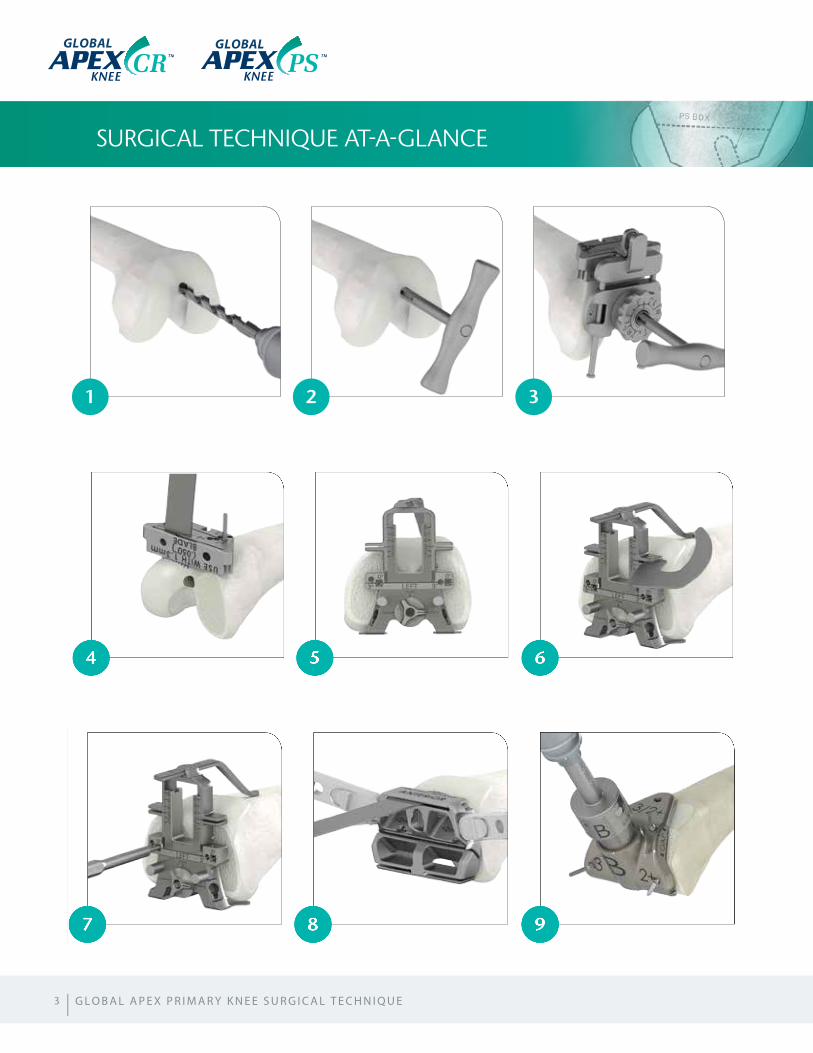
SURGICAL TECHNIQUE AT-A-GLANCE
3
1
4
7
2
5
8
3
6
9
GLOBAL GLOBAL
| G L O B A L A P E X P R I M A R Y K N E E S U R G I C A L T E C H N I Q U E
| 4
10
13
16
11
14
17
12
15
18
PREOPERATIVE PLANNING
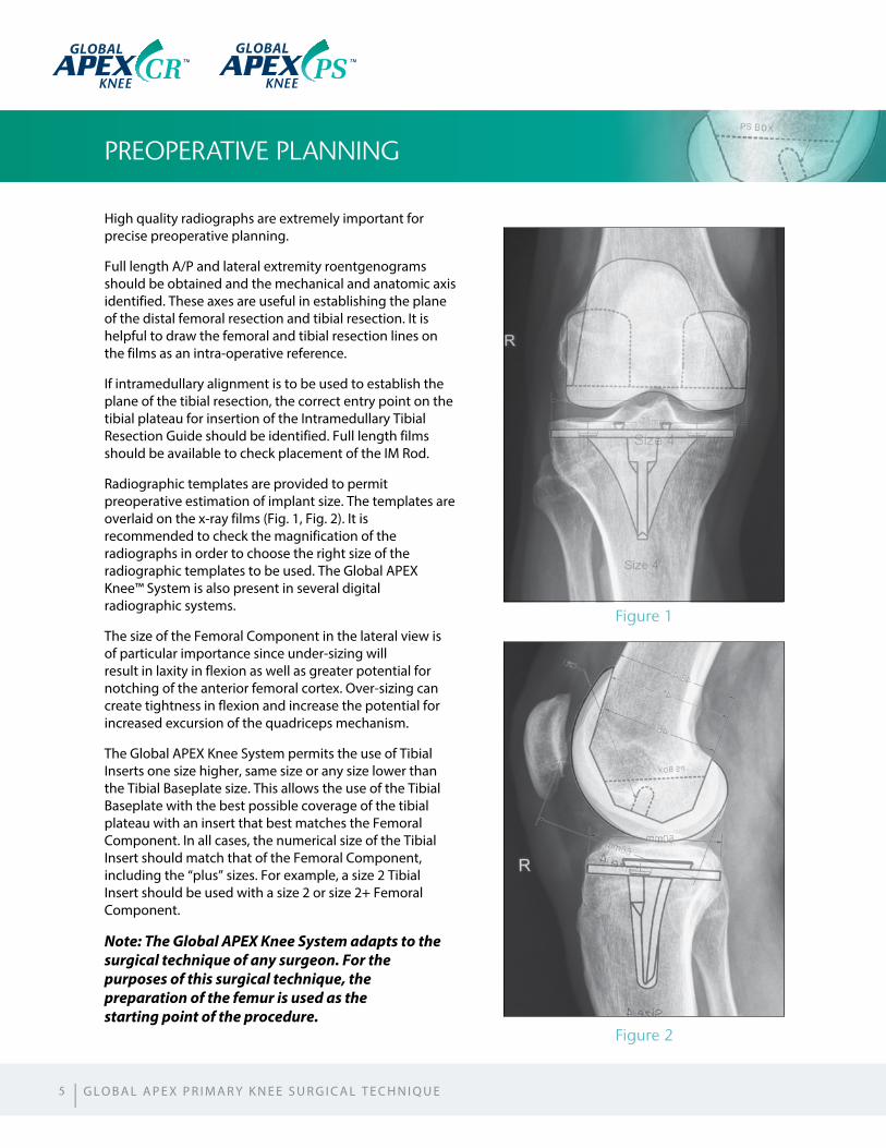
High quality radiographs are extremely important for precise preoperative planning.
Full length A/P and lateral extremity roentgenograms should be obtained and the mechanical and anatomic axis identified. These axes are useful in establishing the plane of the distal femoral resection and tibial resection. It is helpful to draw the femoral and tibial resection lines on the films as an intra-operative reference.
If intramedullary alignment is to be used to establish the plane of the tibial resection, the correct entry point on the tibial plateau for insertion of the Intramedullary Tibial Resection Guide should be identified. Full length films should be available to check placement of the IM Rod.
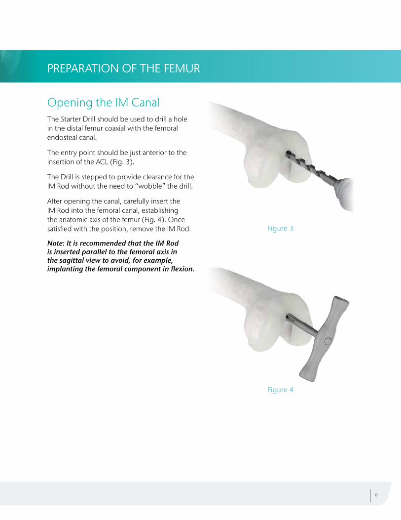
Radiographic templates are provided to permit preoperative estimation of implant size. The templates are overlaid on the x-ray films (Fig. 1, Fig. 2). It is recommended to check the magnification of the radiographs in order to choose the right size of the radiographic templates to be used. The Global APEX Knee™ System is also present in several digital radiographic systems.
The size of the Femoral Component in the lateral view is of particular importance since under-sizing will result in laxity in flexion as well as greater potential for notching of the anterior femoral cortex. Over-sizing can create tightness in flexion and increase the potential for increased excursion of the quadriceps mechanism.
The Global APEX Knee System permits the use of Tibial Inserts one size higher, same size or any size lower than the Tibial Baseplate size. This allows the use of the Tibial Baseplate with the best possible coverage of the tibial plateau with an insert that best matches the Femoral Component. In all cases, the numerical size of the Tibial Insert should match that of the Femoral Component, including the “plus” sizes. For example, a size 2 Tibial Insert should be used with a size 2 or size 2+ Femoral Component.
Note: The Global APEX Knee System adapts to the surgical technique of any surgeon. For the purposes of this surgical technique, the preparation of the femur is used as the starting point of the procedure.
Figure 1
Figure 2
5
GLOBAL GLOBAL
| G L O B A L A P E X P R I M A R Y K N E E S U R G I C A L T E C H N I Q U E
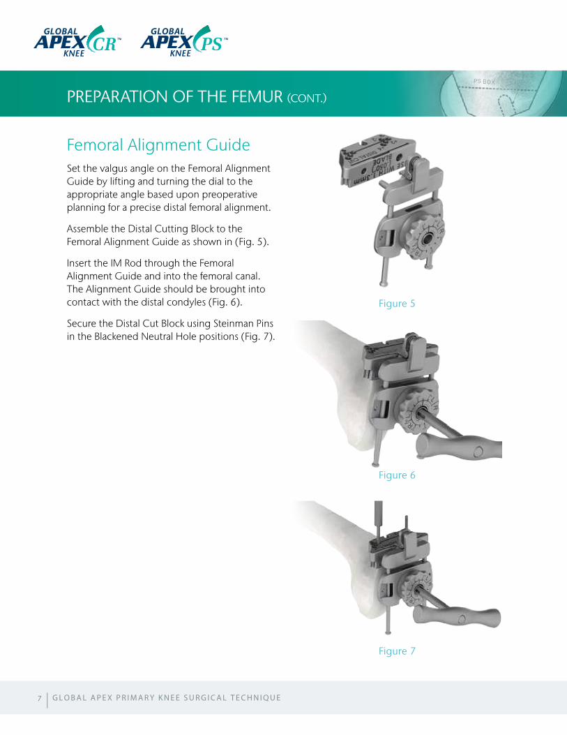
Opening the IM CanalThe Starter Drill should be used to drill a hole in the distal femur coaxial with the femoral endosteal canal.
The entry point should be just anterior to the insertion of the ACL (Fig. 3).
The Drill is stepped to provide clearance for the IM Rod without the need to “wobble” the drill.
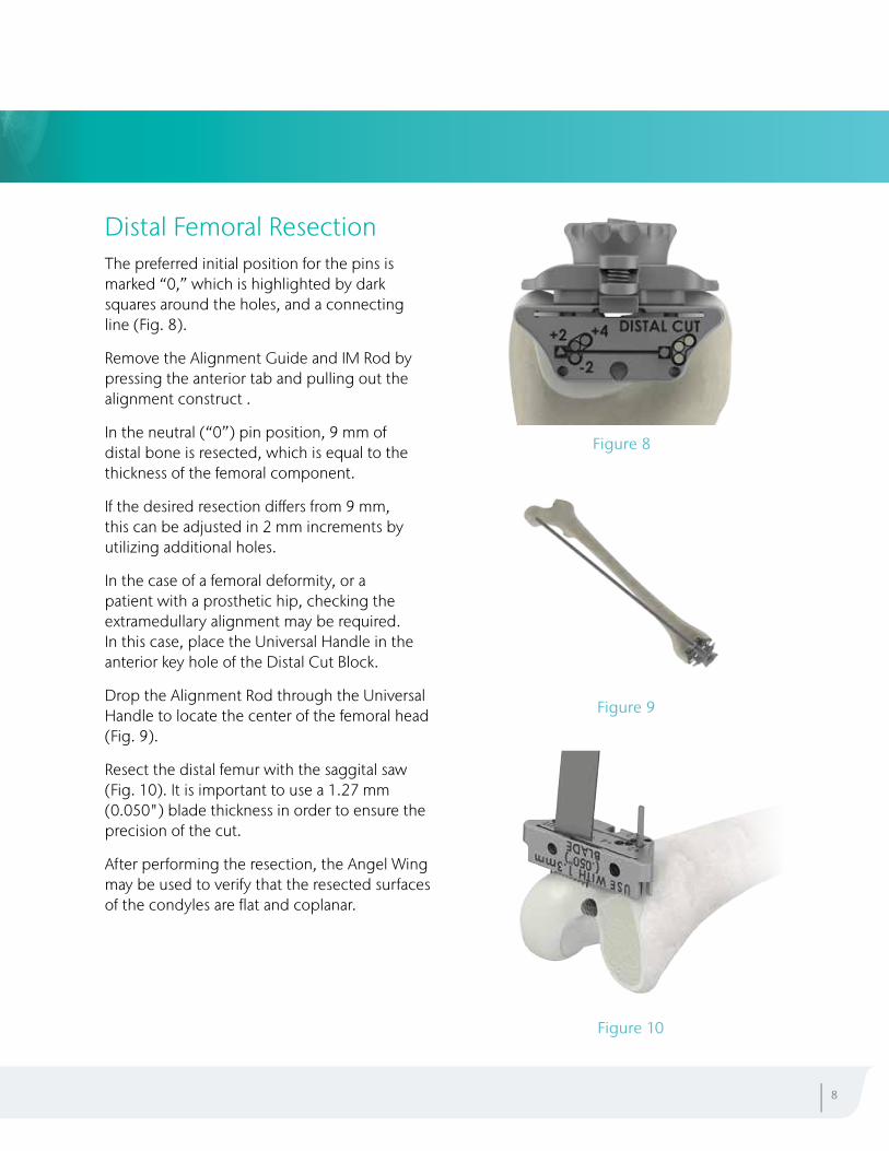
After opening the canal, carefully insert the IM Rod into the femoral canal, establishing the anatomic axis of the femur (Fig. 4). Once satisfied with the position, remove the IM Rod.
Note: It is recommended that the IM Rod is inserted parallel to the femoral axis in the sagittal view to avoid, for example, implanting the femoral component in flexion.
PREPARATION OF THE FEMUR
Figure 3
Figure 4
| 6
Femoral Alignment GuideSet the valgus angle on the Femoral Alignment Guide by lifting and turning the dial to the appropriate angle based upon preoperative planning for a precise distal femoral alignment.
Assemble the Distal Cutting Block to the Femoral Alignment Guide as shown in (Fig. 5).
Insert the IM Rod through the Femoral Alignment Guide and into the femoral canal. The Alignment Guide should be brought into contact with the distal condyles (Fig. 6).
Secure the Distal Cut Block using Steinman Pins in the Blackened Neutral Hole positions (Fig. 7).
PREPARATION OF THE FEMUR (CONT.)
Figure 5
Figure 6
Figure 7
7 | G L O B A L A P E X P R I M A R Y K N E E S U R G I C A L T E C H N I Q U E
GLOBAL GLOBAL
Distal Femoral ResectionThe preferred initial position for the pins is marked “0,” which is highlighted by dark squares around the holes, and a connecting line (Fig. 8).
Remove the Alignment Guide and IM Rod by pressing the anterior tab and pulling out the alignment construct .
In the neutral (“0”) pin position, 9 mm of distal bone is resected, which is equal to the thickness of the femoral component.
If the desired resection differs from 9 mm, this can be adjusted in 2 mm increments by utilizing additional holes.
In the case of a femoral deformity, or a patient with a prosthetic hip, checking the extramedullary alignment may be required. In this case, place the Universal Handle in the anterior key hole of the Distal Cut Block.
Drop the Alignment Rod through the Universal Handle to locate the center of the femoral head (Fig. 9).
Resect the distal femur with the saggital saw (Fig. 10). It is important to use a 1.27 mm (0.050") blade thickness in order to ensure the precision of the cut.
After performing the resection, the Angel Wing may be used to verify that the resected surfaces of the condyles are flat and coplanar.
Figure 8
Figure 9
Figure 10
| 8
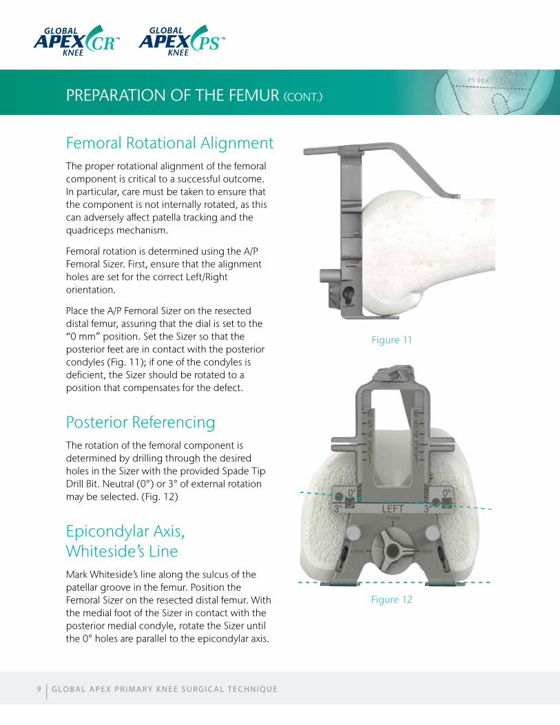
Femoral Rotational AlignmentThe proper rotational alignment of the femoral component is critical to a successful outcome. In particular, care must be taken to ensure that the component is not internally rotated, as this can adversely affect patella tracking and the quadriceps mechanism.
Femoral rotation is determined using the A/P Femoral Sizer. First, ensure that the alignment holes are set for the correct Left/Right orientation.
Place the A/P Femoral Sizer on the resected distal femur, assuring that the dial is set to the “0 mm” position. Set the Sizer so that the posterior feet are in contact with the posterior condyles (Fig. 11); if one of the condyles is deficient, the Sizer should be rotated to a position that compensates for the defect.
Posterior ReferencingThe rotation of the femoral component is determined by drilling through the desired holes in the Sizer with the provided Spade Tip Drill Bit. Neutral (0°) or 3° of external rotation may be selected. (Fig. 12)
Epicondylar Axis, Whiteside’s LineMark Whiteside’s line along the sulcus of the patellar groove in the femur. Position the Femoral Sizer on the resected distal femur. With the medial foot of the Sizer in contact with the posterior medial condyle, rotate the Sizer until the 0° holes are parallel to the epicondylar axis.
PREPARATION OF THE FEMUR (CONT.)
Figure 11
Figure 12
9
GLOBAL GLOBAL
| G L O B A L A P E X P R I M A R Y K N E E S U R G I C A L T E C H N I Q U E
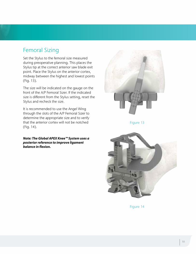
Femoral SizingSet the Stylus to the femoral size measured during preoperative planning. This places the Stylus tip at the correct anterior saw blade exit point. Place the Stylus on the anterior cortex, midway between the highest and lowest points (Fig. 13).
The size will be indicated on the gauge on the front of the A/P Femoral Sizer. If the indicated size is different from the Stylus setting, reset the Stylus and recheck the size.
It is recommended to use the Angel Wing through the slots of the A/P Femoral Sizer to determine the appropriate size and to verify that the anterior cortex will not be notched (Fig. 14).
Note: The Global APEX Knee™ System uses a posterior reference to improve ligament balance in flexion.
| 10
Figure 13
Figure 14
PREPARATION OF THE FEMUR (CONT.)
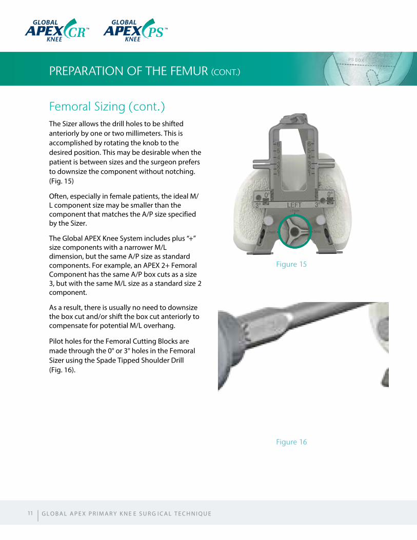
Femoral Sizing (cont.)The Sizer allows the drill holes to be shifted anteriorly by one or two millimeters. This is accomplished by rotating the knob to the desired position. This may be desirable when the patient is between sizes and the surgeon prefers to downsize the component without notching. (Fig. 15)
Often, especially in female patients, the ideal M/L component size may be smaller than the component that matches the A/P size specified by the Sizer.
The Global APEX Knee System includes plus “+” size components with a narrower M/L dimension, but the same A/P size as standard components. For example, an APEX 2+ Femoral Component has the same A/P box cuts as a size 3, but with the same M/L size as a standard size 2 component.
As a result, there is usually no need to downsize the box cut and/or shift the box cut anteriorly to compensate for potential M/L overhang.
Pilot holes for the Femoral Cutting Blocks are made through the 0° or 3° holes in the Femoral Sizer using the Spade Tipped Shoulder Drill (Fig. 16).
Figure 15
Figure 16
11 | G L O B A L A P E X P R I M A R Y K N E E S U R G I C A L T E C H N I Q U E
GLOBAL GLOBAL
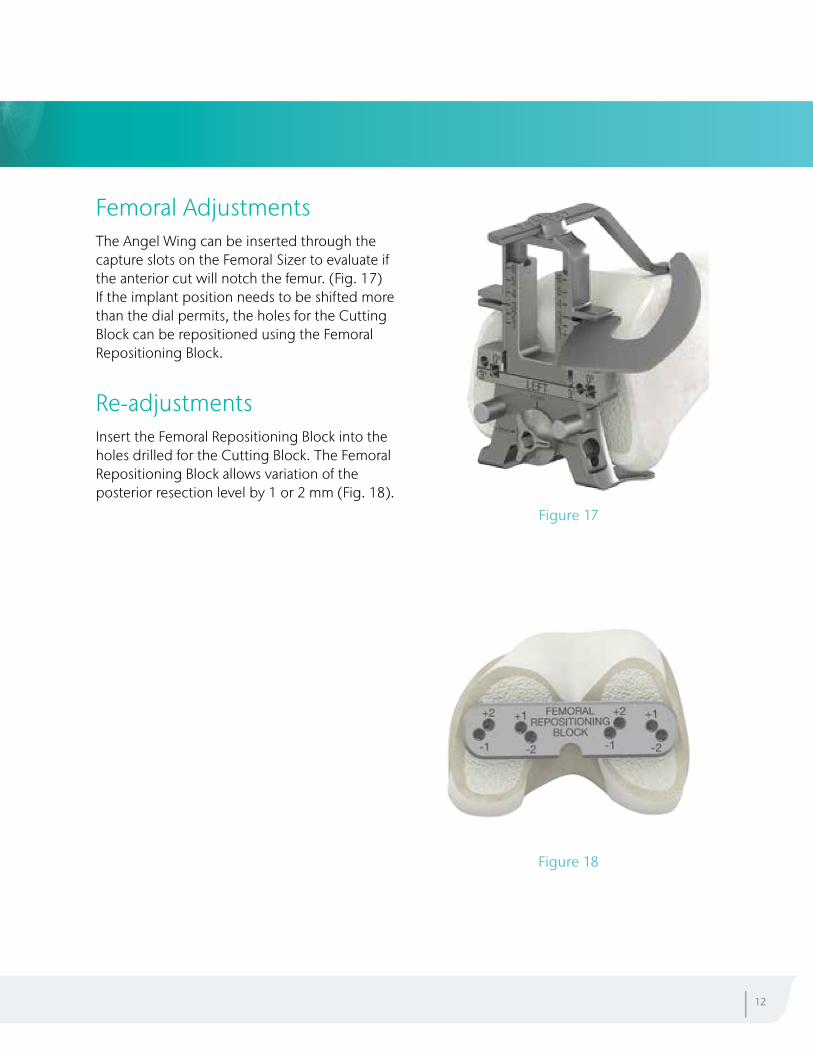
Femoral AdjustmentsThe Angel Wing can be inserted through the capture slots on the Femoral Sizer to evaluate if the anterior cut will notch the femur. (Fig. 17)If the implant position needs to be shifted more than the dial permits, the holes for the Cutting Block can be repositioned using the Femoral Repositioning Block.
Re-adjustmentsInsert the Femoral Repositioning Block into the holes drilled for the Cutting Block. The Femoral Repositioning Block allows variation of the posterior resection level by 1 or 2 mm (Fig. 18).
| 12
Figure 17
Figure 18
PREPARATION OF THE FEMUR (CONT.)
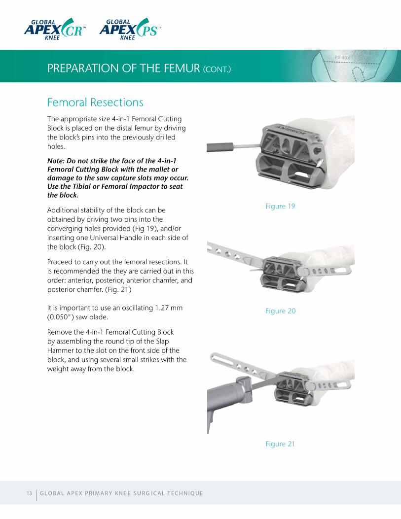
Femoral ResectionsThe appropriate size 4-in-1 Femoral Cutting Block is placed on the distal femur by driving the block’s pins into the previously drilled holes.
Note: Do not strike the face of the 4-in-1 Femoral Cutting Block with the mallet or damage to the saw capture slots may occur. Use the Tibial or Femoral Impactor to seat the block.
Additional stability of the block can be obtained by driving two pins into the converging holes provided (Fig 19), and/or inserting one Universal Handle in each side of the block (Fig. 20).
Proceed to carry out the femoral resections. It is recommended the they are carried out in this order: anterior, posterior, anterior chamfer, and posterior chamfer. (Fig. 21)
It is important to use an oscillating 1.27 mm (0.050") saw blade.
Remove the 4-in-1 Femoral Cutting Block by assembling the round tip of the Slap Hammer to the slot on the front side of the block, and using several small strikes with the weight away from the block.
13
Figure 19
Figure 20
Figure 21
GLOBAL GLOBAL
| G L O B A L A P E X P R I M A R Y K N E E S U R G I C A L T E C H N I Q U E
Femoral Component SelectionThe selection of the components to be used can be delayed until the final trial reduction (examples: CR Femoral Component: with Congruent Tibial Insert or with Ultra Congruent Tibial Insert; PS Femoral Component: with PS Tibial Insert, etc.).
If it has pre-operatively been decided to use an Global APEX PS™ Femoral Component, it is now time to prepare the femur for the PS Cylindrical Resection.
Note: It is recommended not to drill the holes for the CR/CS Femoral Component Pegs until the final trial reduction has occurred and the final M/L position of the component has been determined.
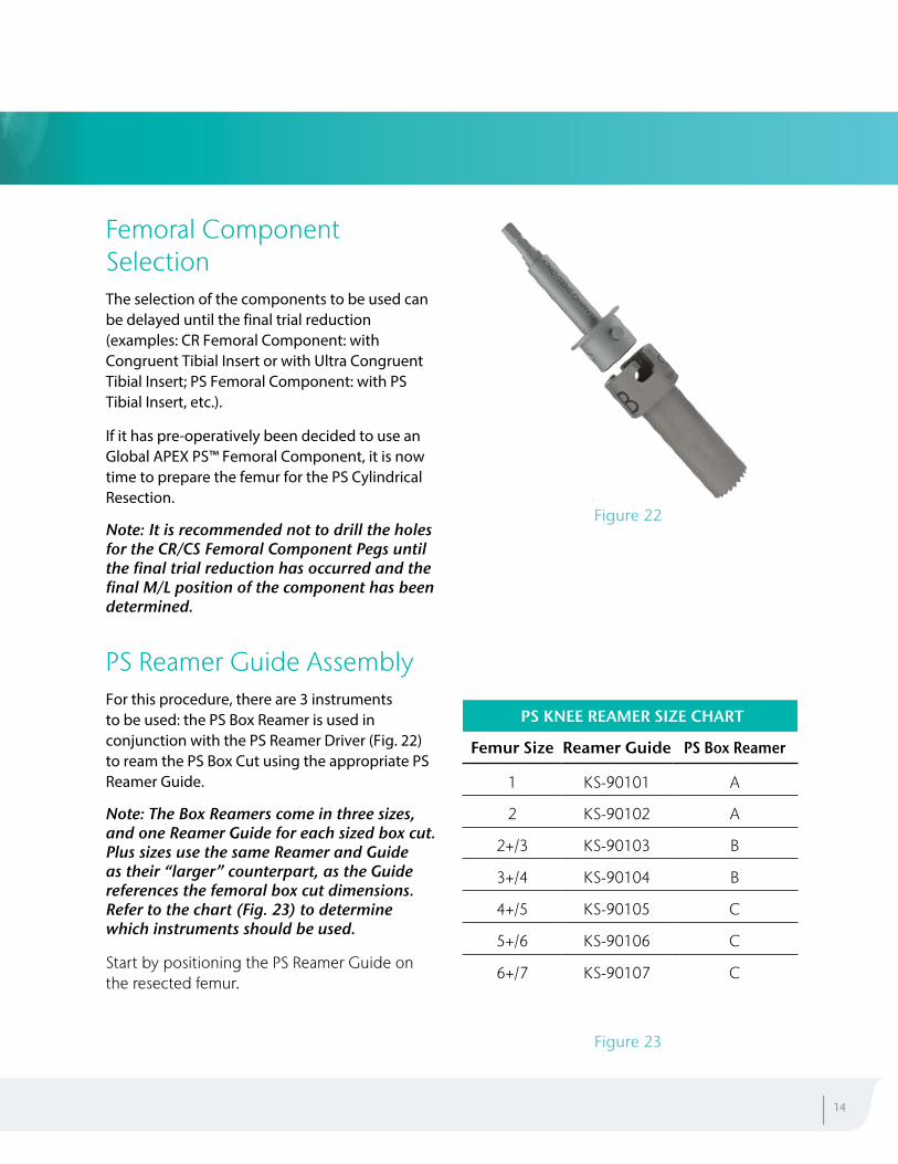
PS Reamer Guide AssemblyFor this procedure, there are 3 instruments to be used: the PS Box Reamer is used in conjunction with the PS Reamer Driver (Fig. 22) to ream the PS Box Cut using the appropriate PS Reamer Guide.
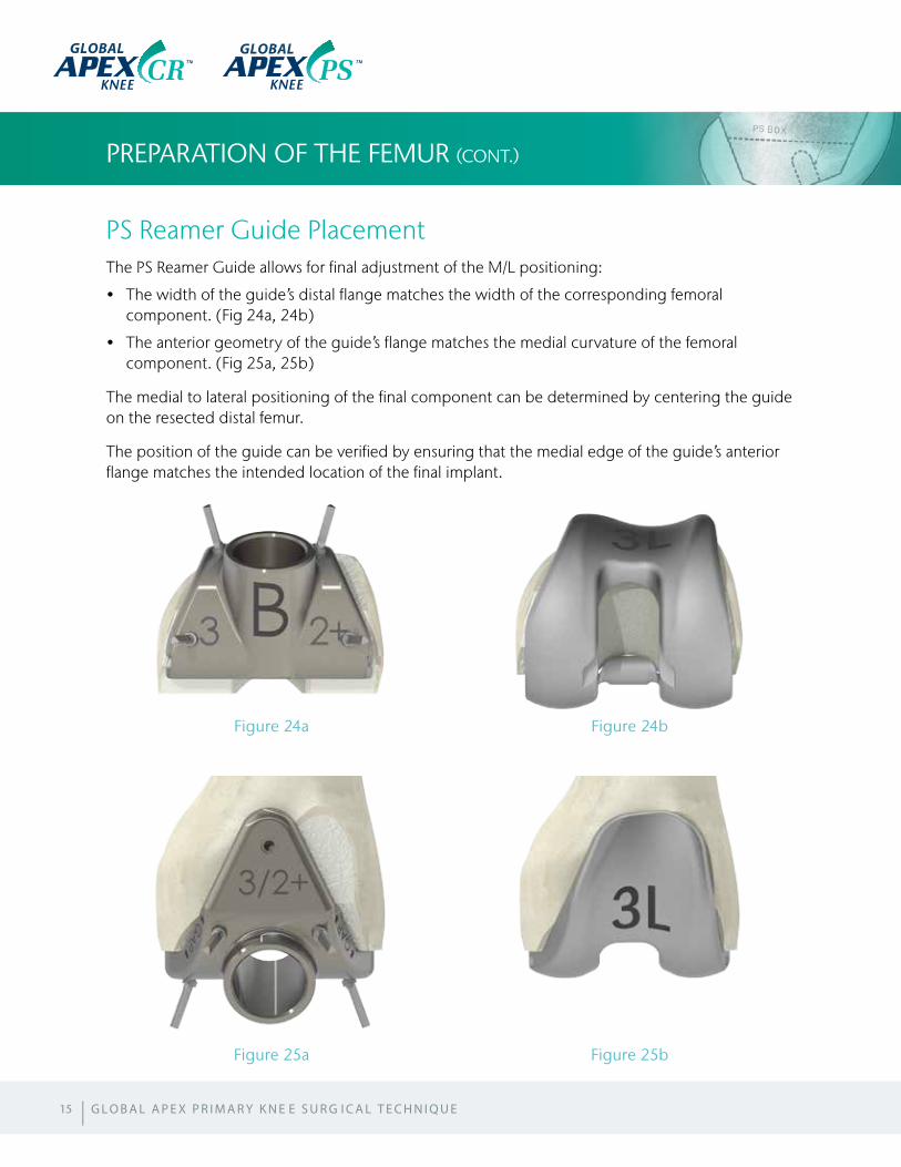
Note: The Box Reamers come in three sizes, and one Reamer Guide for each sized box cut. Plus sizes use the same Reamer and Guide as their “larger” counterpart, as the Guide references the femoral box cut dimensions. Refer to the chart (Fig. 23) to determine which instruments should be used.
Start by positioning the PS Reamer Guide on the resected femur.
| 14
Figure 22
Figure 23
PS KNEE REAMER SIZE CHART
Femur Size Reamer Guide PS Box Reamer
1 KS-90101 A
2 KS-90102 A
2+/3 KS-90103 B
3+/4 KS-90104 B
4+/5 KS-90105 C
5+/6 KS-90106 C
6+/7 KS-90107 C
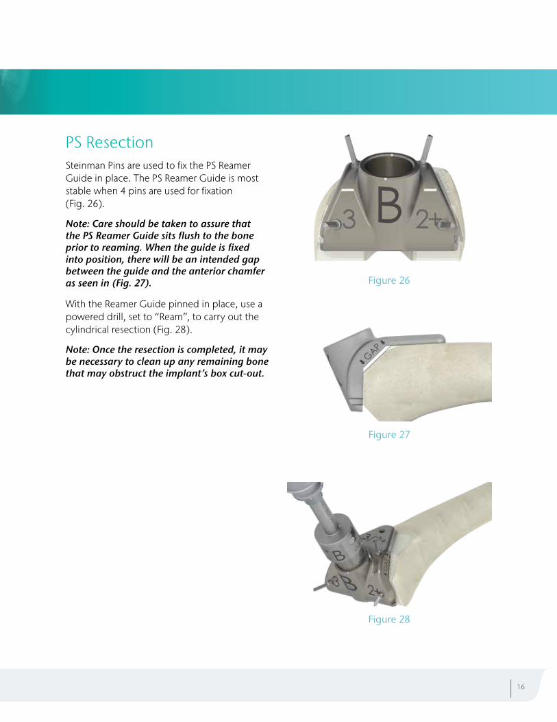
PS Reamer Guide PlacementThe PS Reamer Guide allows for final adjustment of the M/L positioning:
• The width of the guide’s distal flange matches the width of the corresponding femoralcomponent. (Fig 24a, 24b)
• The anterior geometry of the guide’s flange matches the medial curvature of the femoralcomponent. (Fig 25a, 25b)
The medial to lateral positioning of the final component can be determined by centering the guide on the resected distal femur.
The position of the guide can be verified by ensuring that the medial edge of the guide’s anterior flange matches the intended location of the final implant.
PREPARATION OF THE FEMUR (CONT.)
15
Figure 24a
Figure 25a
Figure 24b
Figure 25b
GLOBAL GLOBAL
| G L O B A L A P E X P R I M A R Y K N E E S U R G I C A L T E C H N I Q U E
PS ResectionSteinman Pins are used to fix the PS Reamer Guide in place. The PS Reamer Guide is most stable when 4 pins are used for fixation (Fig. 26).
Note: Care should be taken to assure that the PS Reamer Guide sits flush to the bone prior to reaming. When the guide is fixed into position, there will be an intended gap between the guide and the anterior chamfer as seen in (Fig. 27).
With the Reamer Guide pinned in place, use a powered drill, set to “Ream”, to carry out the cylindrical resection (Fig. 28).
Note: Once the resection is completed, it may be necessary to clean up any remaining bone that may obstruct the implant’s box cut-out.
| 16
Figure 28
Figure 27
Figure 26
PREPARATION OF THE TIBIA
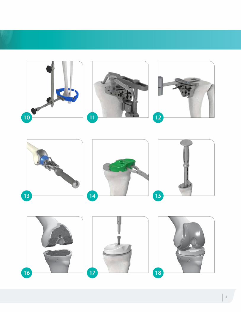
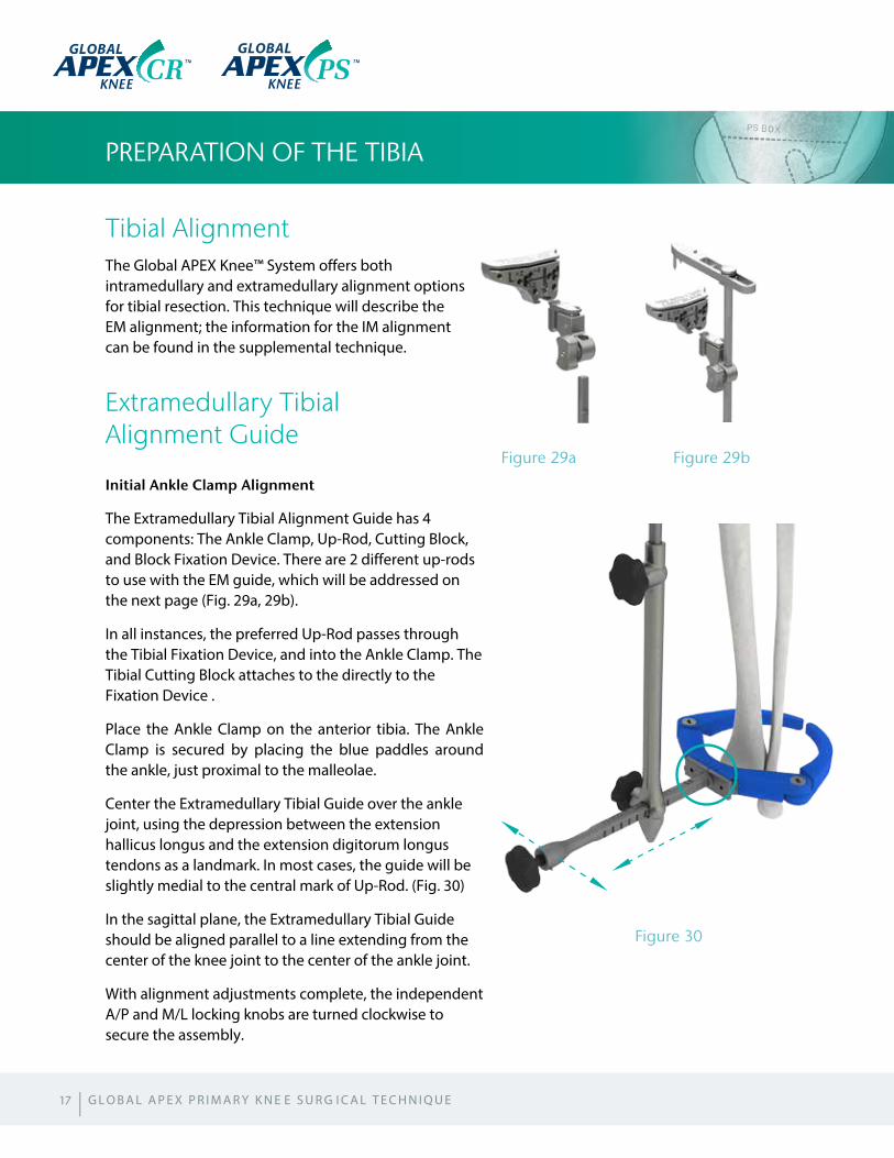
Tibial AlignmentThe Global APEX Knee™ System offers both intramedullary and extramedullary alignment options for tibial resection. This technique will describe the EM alignment; the information for the IM alignment can be found in the supplemental technique.
Extramedullary Tibial Alignment Guide
Initial Ankle Clamp Alignment
The Extramedullary Tibial Alignment Guide has 4 components: The Ankle Clamp, Up-Rod, Cutting Block, and Block Fixation Device. There are 2 different up-rods to use with the EM guide, which will be addressed on the next page (Fig. 29a, 29b).
In all instances, the preferred Up-Rod passes through the Tibial Fixation Device, and into the Ankle Clamp. The Tibial Cutting Block attaches to the directly to the Fixation Device .
Place the Ankle Clamp on the anterior tibia. The Ankle Clamp is secured by placing the blue paddles around the ankle, just proximal to the malleolae.
Center the Extramedullary Tibial Guide over the ankle joint, using the depression between the extension hallicus longus and the extension digitorum longus tendons as a landmark. In most cases, the guide will be slightly medial to the central mark of Up-Rod. (Fig. 30)
In the sagittal plane, the Extramedullary Tibial Guide should be aligned parallel to a line extending from the center of the knee joint to the center of the ankle joint.
With alignment adjustments complete, the independent A/P and M/L locking knobs are turned clockwise to secure the assembly.
17
Figure 30
Figure 29a Figure 29b
GLOBALGLOBAL
| G L O B A L A P E X P R I M A R Y K N E E S U R G I C A L T E C H N I Q U E
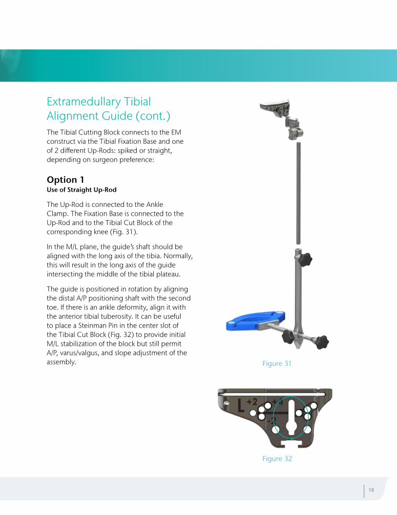
Extramedullary Tibial Alignment Guide (cont.)The Tibial Cutting Block connects to the EM construct via the Tibial Fixation Base and one of 2 different Up-Rods: spiked or straight, depending on surgeon preference:
Option 1 Use of Straight Up-Rod
The Up-Rod is connected to the Ankle Clamp. The Fixation Base is connected to the Up-Rod and to the Tibial Cut Block of the corresponding knee (Fig. 31).
In the M/L plane, the guide’s shaft should be aligned with the long axis of the tibia. Normally, this will result in the long axis of the guide intersecting the middle of the tibial plateau.
The guide is positioned in rotation by aligning the distal A/P positioning shaft with the second toe. If there is an ankle deformity, align it with the anterior tibial tuberosity. It can be useful to place a Steinman Pin in the center slot of the Tibial Cut Block (Fig. 32) to provide initial M/L stabilization of the block but still permit A/P, varus/valgus, and slope adjustment of the assembly.
| 18
Figure 32
Figure 31
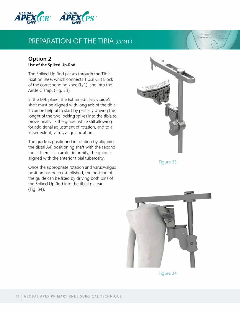
Option 2 Use of the Spiked Up-Rod
The Spiked Up-Rod passes through the Tibial Fixation Base, which connects Tibial Cut Block of the corresponding knee (L/R), and into the Ankle Clamp. (Fig. 33)
In the M/L plane, the Extramedullary Guide’s shaft must be aligned with long axis of the tibia. It can be helpful to start by partially driving the longer of the two locking spikes into the tibia to provisionally fix the guide, while still allowing for additional adjustment of rotation, and to a lesser extent, varus/valgus position.
The guide is positioned in rotation by aligning the distal A/P positioning shaft with the second toe. If there is an ankle deformity, the guide is aligned with the anterior tibial tuberosity.
Once the appropriate rotation and varus/valgus position has been established, the position of the guide can be fixed by driving both pins of the Spiked Up-Rod into the tibial plateau (Fig. 34).
PREPARATION OF THE TIBIA (CONT.)
19
Figure 33
Figure 34
GLOBAL GLOBAL
| G L O B A L A P E X P R I M A R Y K N E E S U R G I C A L T E C H N I Q U E
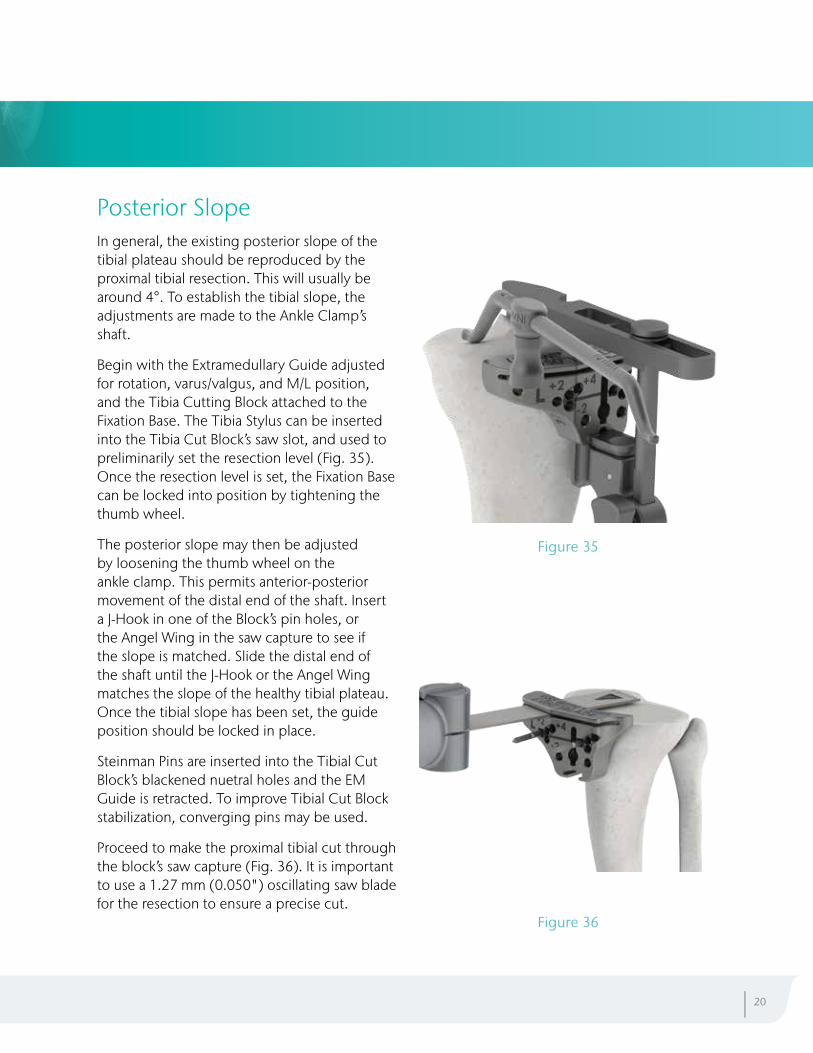
Posterior Slope In general, the existing posterior slope of the tibial plateau should be reproduced by the proximal tibial resection. This will usually be around 4°. To establish the tibial slope, the adjustments are made to the Ankle Clamp’s shaft.
Begin with the Extramedullary Guide adjusted for rotation, varus/valgus, and M/L position, and the Tibia Cutting Block attached to the Fixation Base. The Tibia Stylus can be inserted into the Tibia Cut Block’s saw slot, and used to preliminarily set the resection level (Fig. 35). Once the resection level is set, the Fixation Base can be locked into position by tightening the thumb wheel.
The posterior slope may then be adjusted by loosening the thumb wheel on the ankle clamp. This permits anterior-posterior movement of the distal end of the shaft. Insert a J-Hook in one of the Block’s pin holes, or the Angel Wing in the saw capture to see if the slope is matched. Slide the distal end of the shaft until the J-Hook or the Angel Wing matches the slope of the healthy tibial plateau. Once the tibial slope has been set, the guide position should be locked in place.
Steinman Pins are inserted into the Tibial Cut Block’s blackened nuetral holes and the EM Guide is retracted. To improve Tibial Cut Block stabilization, converging pins may be used.
Proceed to make the proximal tibial cut through the block’s saw capture (Fig. 36). It is important to use a 1.27 mm (0.050") oscillating saw blade for the resection to ensure a precise cut.
| 20
Figure 35
Figure 36
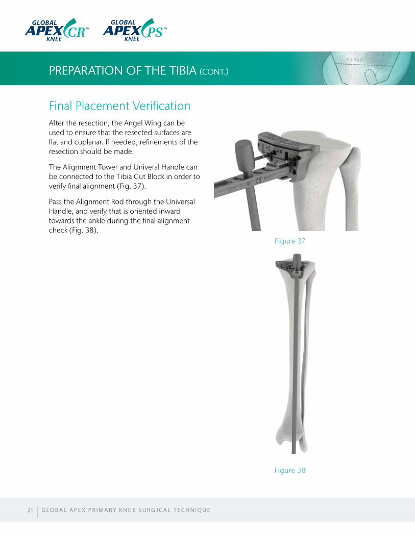
Final Placement VerificationAfter the resection, the Angel Wing can be used to ensure that the resected surfaces are flat and coplanar. If needed, refinements of the resection should be made.
The Alignment Tower and Univeral Handle can be connected to the Tibia Cut Block in order to verify final alignment (Fig. 37).
Pass the Alignment Rod through the Universal Handle, and verify that is oriented inward towards the ankle during the final alignment check (Fig. 38).
PREPARATION OF THE TIBIA (CONT.)
21
Figure 38
Figure 37
| G L O B A L A P E X P R I M A R Y K N E E S U R G I C A L T E C H N I Q U E
GLOBAL GLOBAL
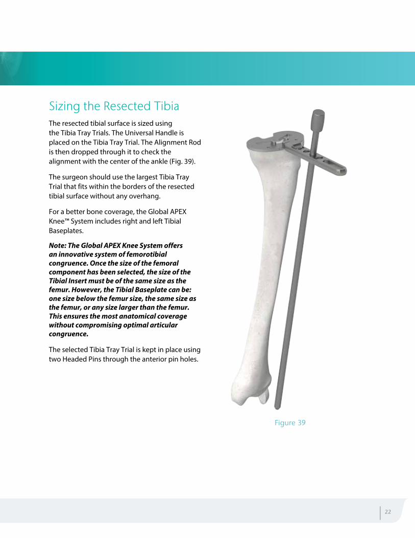
Sizing the Resected TibiaThe resected tibial surface is sized using the Tibia Tray Trials. The Universal Handle is placed on the Tibia Tray Trial. The Alignment Rod is then dropped through it to check the alignment with the center of the ankle (Fig. 39).
The surgeon should use the largest Tibia Tray Trial that fits within the borders of the resected tibial surface without any overhang.
For a better bone coverage, the Global APEX Knee™ System includes right and left Tibial Baseplates.
Note: The Global APEX Knee System offers an innovative system of femorotibial congruence. Once the size of the femoral component has been selected, the size of the Tibial Insert must be of the same size as the femur. However, the Tibial Baseplate can be: one size below the femur size, the same size as the femur, or any size larger than the femur. This ensures the most anatomical coverage without compromising optimal articular congruence.
The selected Tibia Tray Trial is kept in place using two Headed Pins through the anterior pin holes.
| 22
Figure 39
PREPARATION OF THE PATELLA
Patella SizingThe Global APEX Knee™ System offers two methods of patella resection: Using the Patella Resection guide, or the Patella Reaming System.
Note: For the purpose of this surgical technique, the Patella Resection Guide will be discussed. The use of the Patella Reaming System is outlined in the supplemental technique.
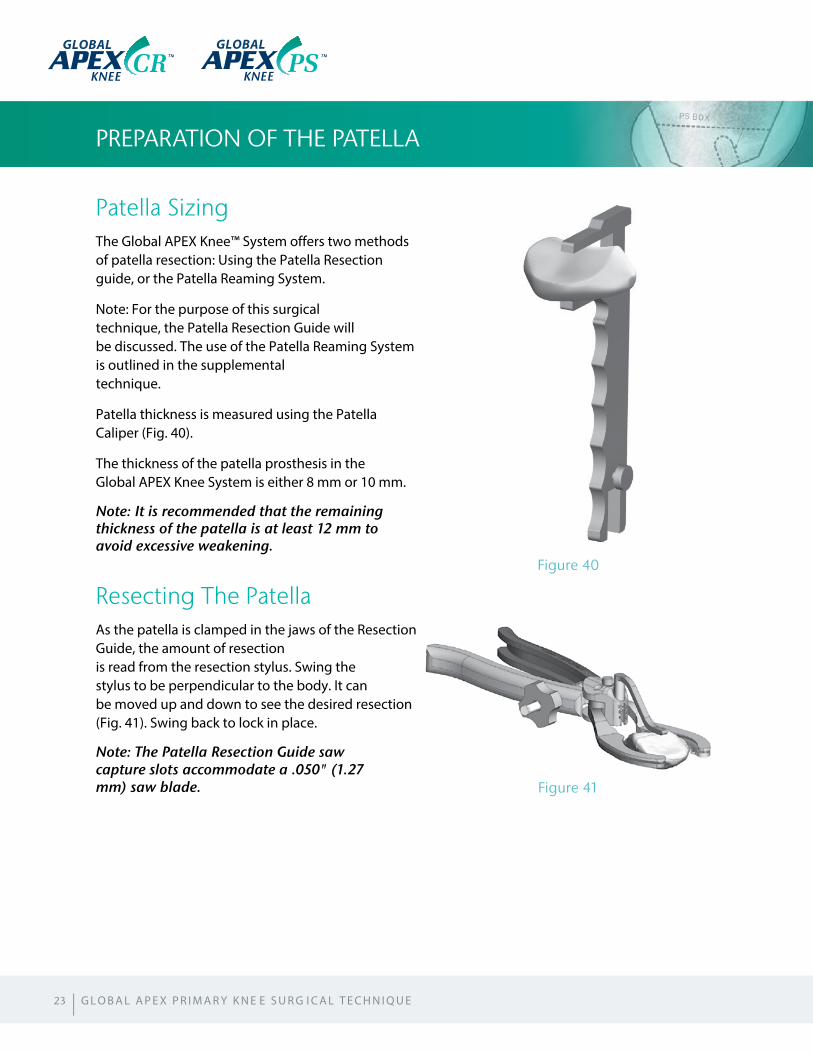
Patella thickness is measured using the Patella Caliper (Fig. 40).
The thickness of the patella prosthesis in the Global APEX Knee System is either 8 mm or 10 mm.
Note: It is recommended that the remaining thickness of the patella is at least 12 mm to avoid excessive weakening.
Resecting The PatellaAs the patella is clamped in the jaws of the Resection Guide, the amount of resection is read from the resection stylus. Swing the stylus to be perpendicular to the body. It can be moved up and down to see the desired resection (Fig. 41). Swing back to lock in place.
Note: The Patella Resection Guide saw capture slots accommodate a .050" (1.27 mm) saw blade.
23
Figure 41
Figure 40
| G L O B A L A P E X P R I M A R Y K N E E S U R G I C A L T E C H N I Q U E
GLOBAL GLOBAL
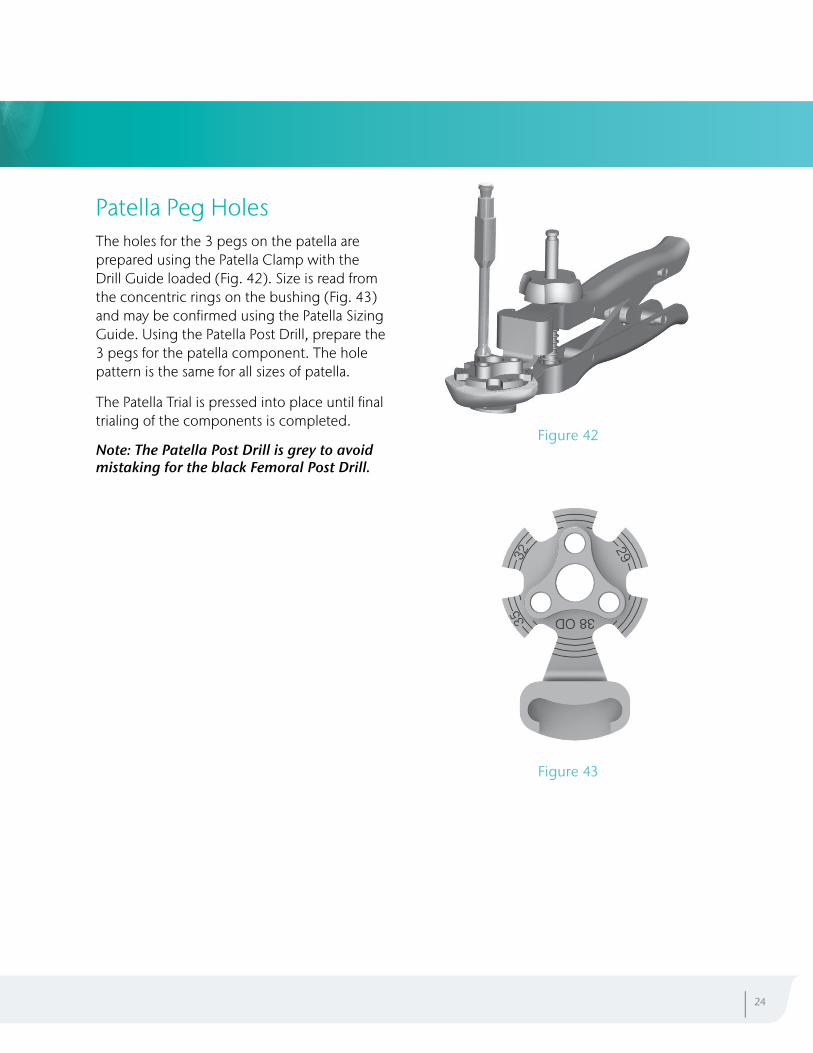
Patella Peg HolesThe holes for the 3 pegs on the patella are prepared using the Patella Clamp with the Drill Guide loaded (Fig. 42). Size is read from the concentric rings on the bushing (Fig. 43) and may be confirmed using the Patella Sizing Guide. Using the Patella Post Drill, prepare the 3 pegs for the patella component. The hole pattern is the same for all sizes of patella.
The Patella Trial is pressed into place until final trialing of the components is completed.
Note: The Patella Post Drill is grey to avoid mistaking for the black Femoral Post Drill.
| 24
Figure 42
Figure 43
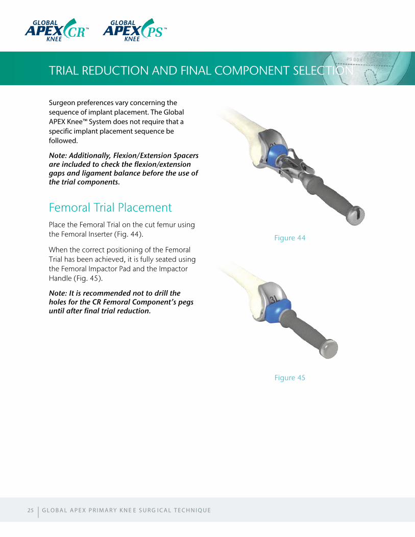
Surgeon preferences vary concerning the sequence of implant placement. The Global APEX Knee™ System does not require that a specific implant placement sequence be followed.
Note: Additionally, Flexion/Extension Spacers are included to check the flexion/extension gaps and ligament balance before the use of the trial components.
Femoral Trial PlacementPlace the Femoral Trial on the cut femur using the Femoral Inserter (Fig. 44).
When the correct positioning of the Femoral Trial has been achieved, it is fully seated using the Femoral Impactor Pad and the Impactor Handle (Fig. 45).
Note: It is recommended not to drill the holes for the CR Femoral Component’s pegs until after final trial reduction.
TRIAL REDUCTION AND FINAL COMPONENT SELECTION
Figure 44
Figure 45
25
GLOBAL GLOBAL
| G L O B A L A P E X P R I M A R Y K N E E S U R G I C A L T E C H N I Q U E
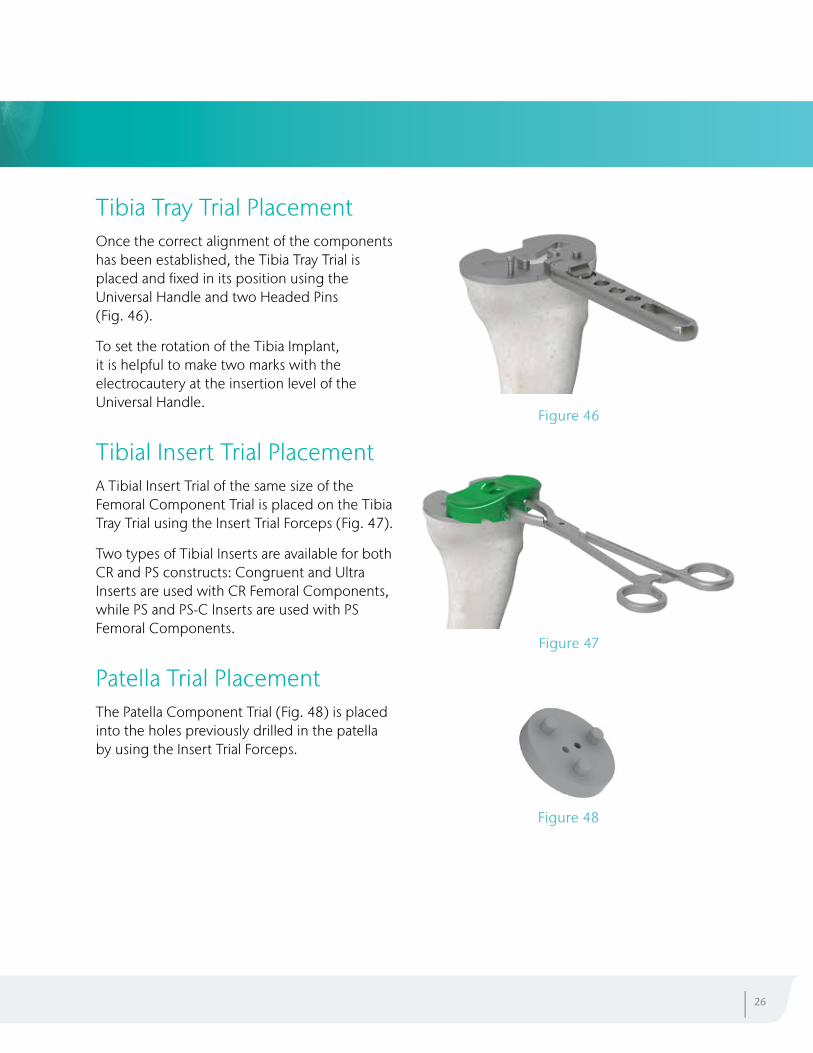
Tibia Tray Trial PlacementOnce the correct alignment of the components has been established, the Tibia Tray Trial is placed and fixed in its position using the Universal Handle and two Headed Pins (Fig. 46).
To set the rotation of the Tibia Implant, it is helpful to make two marks with the electrocautery at the insertion level of the Universal Handle.
Tibial Insert Trial PlacementA Tibial Insert Trial of the same size of the Femoral Component Trial is placed on the Tibia Tray Trial using the Insert Trial Forceps (Fig. 47).
Two types of Tibial Inserts are available for both CR and PS constructs: Congruent and Ultra Inserts are used with CR Femoral Components, while PS and PS-C Inserts are used with PS Femoral Components.
Patella Trial PlacementThe Patella Component Trial (Fig. 48) is placed into the holes previously drilled in the patella by using the Insert Trial Forceps.
Figure 46
Figure 47
Figure 48
| 26
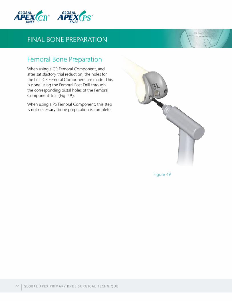
Femoral Bone PreparationWhen using a CR Femoral Component, and after satisfactory trial reduction, the holes for the final CR Femoral Component are made. This is done using the Femoral Post Drill through the corresponding distal holes of the Femoral Component Trial (Fig. 49).
When using a PS Femoral Component, this step is not necessary; bone preparation is complete.
FINAL BONE PREPARATION
Figure 49
27 | G L O B A L A P E X P R I M A R Y K N E E S U R G I C A L T E C H N I Q U E
GLOBAL GLOBAL
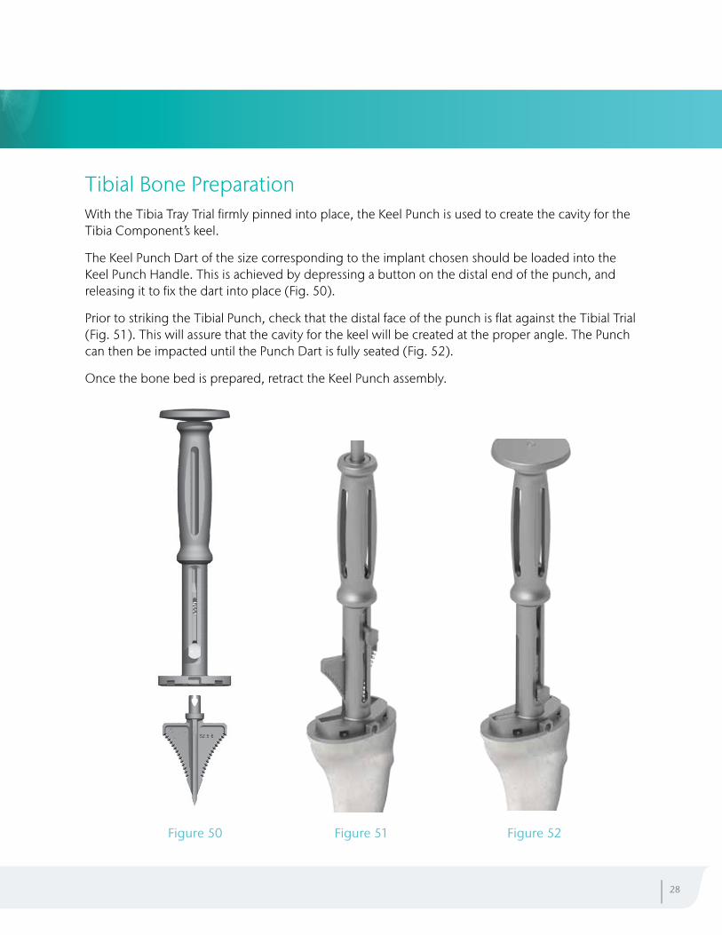
Tibial Bone PreparationWith the Tibia Tray Trial firmly pinned into place, the Keel Punch is used to create the cavity for the Tibia Component’s keel.
The Keel Punch Dart of the size corresponding to the implant chosen should be loaded into the Keel Punch Handle. This is achieved by depressing a button on the distal end of the punch, and releasing it to fix the dart into place (Fig. 50).
Prior to striking the Tibial Punch, check that the distal face of the punch is flat against the Tibial Trial (Fig. 51). This will assure that the cavity for the keel will be created at the proper angle. The Punch can then be impacted until the Punch Dart is fully seated (Fig. 52).
Once the bone bed is prepared, retract the Keel Punch assembly.
| 28
Figure 50 Figure 51 Figure 52
FINAL COMPONENT IMPLANTATION
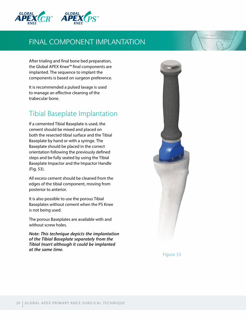
After trialing and final bone bed preparation, the Global APEX Knee™ final components are implanted. The sequence to implant the components is based on surgeon preference.
It is recommended a pulsed lavage is used to manage an effective cleaning of the trabecular bone.
Tibial Baseplate ImplantationIf a cemented Tibial Baseplate is used, the cement should be mixed and placed on both the resected tibial surface and the Tibial Baseplate by hand or with a syringe. The Baseplate should be placed in the correct orientation following the previously defined steps and be fully seated by using the Tibial Baseplate Impactor and the Impactor Handle (Fig. 53).
All excess cement should be cleaned from the edges of the tibial component, moving from posterior to anterior.
It is also possible to use the porous Tibial Baseplates without cement when the PS Knee is not being used.
The porous Baseplates are available with and without screw holes.
Note: This technique depicts the implantation of the Tibial Baseplate separately from the Tibial Insert although it could be implanted at the same time.
29
Figure 53
GLOBAL GLOBAL
| G L O B A L A P E X P R I M A R Y K N E E S U R G I C A L T E C H N I Q U E
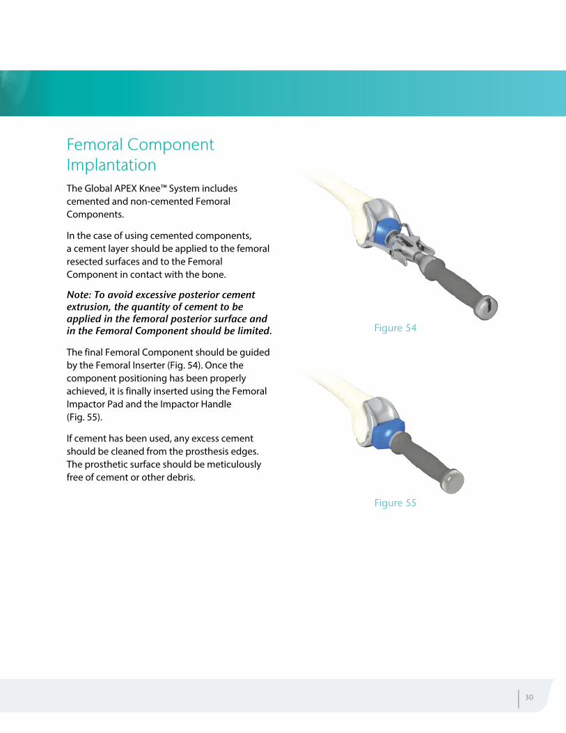
Femoral Component ImplantationThe Global APEX Knee™ System includes cemented and non-cemented Femoral Components.
In the case of using cemented components, a cement layer should be applied to the femoral resected surfaces and to the Femoral Component in contact with the bone.
Note: To avoid excessive posterior cement extrusion, the quantity of cement to be applied in the femoral posterior surface and in the Femoral Component should be limited.
The final Femoral Component should be guided by the Femoral Inserter (Fig. 54). Once the component positioning has been properly achieved, it is finally inserted using the Femoral Impactor Pad and the Impactor Handle (Fig. 55).
If cement has been used, any excess cement should be cleaned from the prosthesis edges. The prosthetic surface should be meticulously free of cement or other debris.
Figure 54
Figure 55
| 30
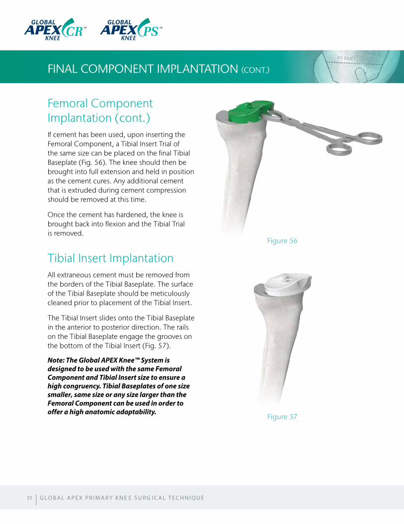
Femoral Component Implantation (cont.)If cement has been used, upon inserting the Femoral Component, a Tibial Insert Trial of the same size can be placed on the final Tibial Baseplate (Fig. 56). The knee should then be brought into full extension and held in position as the cement cures. Any additional cement that is extruded during cement compression should be removed at this time.
Once the cement has hardened, the knee is brought back into flexion and the Tibial Trial is removed.
Tibial Insert ImplantationAll extraneous cement must be removed from the borders of the Tibial Baseplate. The surface of the Tibial Baseplate should be meticulously cleaned prior to placement of the Tibial Insert.
The Tibial Insert slides onto the Tibial Baseplate in the anterior to posterior direction. The rails on the Tibial Baseplate engage the grooves on the bottom of the Tibial Insert (Fig. 57).
Note: The Global APEX Knee™ System is designed to be used with the same Femoral Component and Tibial Insert size to ensure a high congruency. Tibial Baseplates of one size smaller, same size or any size larger than the Femoral Component can be used in order to offer a high anatomic adaptability.
FINAL COMPONENT IMPLANTATION (CONT.)
31
Figure 57
Figure 56
| G L O B A L A P E X P R I M A R Y K N E E S U R G I C A L T E C H N I Q U E
GLOBAL GLOBAL
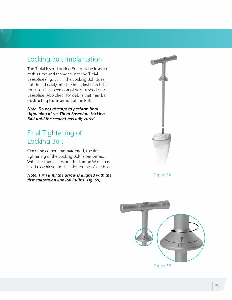
Locking Bolt ImplantationThe Tibial Insert Locking Bolt may be inserted at this time and threaded into the Tibial Baseplate (Fig. 58). If the Locking Bolt does not thread easily into the hole, first check that the Insert has been completely pushed onto Baseplate. Also check for debris that may be obstructing the insertion of the Bolt.
Note: Do not attempt to perform final tightening of the Tibial Baseplate Locking Bolt until the cement has fully cured.
Final Tightening of Locking BoltOnce the cement has hardened, the final tightening of the Locking Bolt is performed. With the knee in flexion, the Torque Wrench is used to achieve the final tightening of the bolt.
Note: Turn until the arrow is aligned with the first calibration line (60 in-lbs) (Fig. 59).
| 32
Figure 59
Figure 58
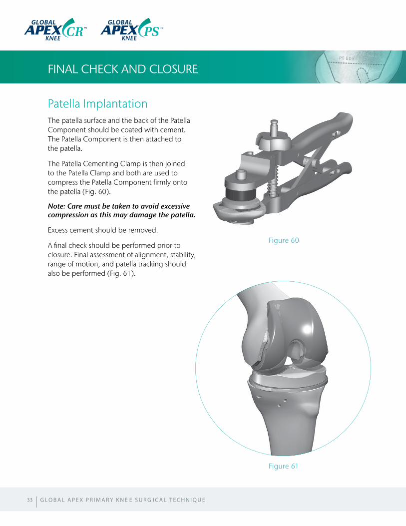
Patella ImplantationThe patella surface and the back of the Patella Component should be coated with cement. The Patella Component is then attached to the patella.
The Patella Cementing Clamp is then joined to the Patella Clamp and both are used to compress the Patella Component firmly onto the patella (Fig. 60).
Note: Care must be taken to avoid excessive compression as this may damage the patella.
Excess cement should be removed.
A final check should be performed prior to closure. Final assessment of alignment, stability, range of motion, and patella tracking should also be performed (Fig. 61).
FINAL CHECK AND CLOSURE
33
Figure 61
Figure 60
GLOBAL GLOBAL
| G L O B A L A P E X P R I M A R Y K N E E S U R G I C A L T E C H N I Q U E
SIZING CHART
| 34
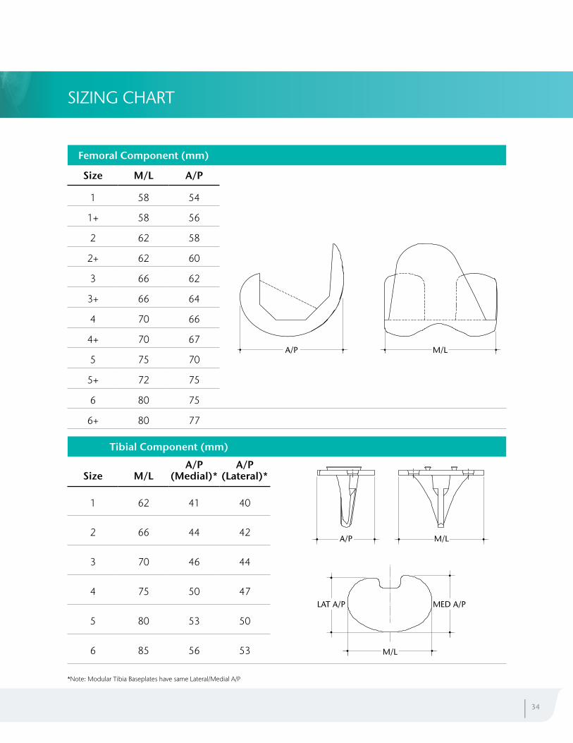
Femoral Component (mm)
Size M/L A/P
1 58 54
1+ 58 56
2 62 58
2+ 62 60
3 66 62
3+ 66 64
4 70 66
4+ 70 67
5 75 70
5+ 72 75
6 80 75
6+ 80 77
M/LA/P
Tibial Component (mm)
Size M/LA/P
(Medial)*A/P
(Lateral)*
1 62 41 40
2 66 44 42
3 70 46 44
4 75 50 47
5 80 53 50
6 85 56 53
MED A/PLAT A/P
M/L
A/P M/L
*Note: Modular Tibia Baseplates have same Lateral/Medial A/P
APEX Knee, APEX RK, APEX PS and APEX CR are trademarks of OMNIlife science, Inc.
GLOBAL
GLOBAL
GLOBAL
Manufactured by:Global Manufacturing Technology Pty Ltd Unit 10, 7 Meridian Place, Norwest Business Park Baulkham Hills, NSW 2153, Australia
GKL-018 Revision 0