Embed Size (px)
Citation preview

TAMURA CORPORATION 43352 Business Park Drive. | P.O. Box 892230 Temecula, CA 92589-2230 | www.tamuracorp.com
USATel: 800-872-6624Fax: 909-676-9482
JapanTel: 81 (0)3 3978-2111Fax: 81 (0)3 3923-0230
United KingdomTel: 44 (0) 1380 731 700Fax: 44 (0) 1380 731 702
Hong KongTel: 852-2389-4321Fax: 852-2341-9689
GL
OB
AL
SO
LU
TIO
NS
CA
TA
LO
G | T
AM
UR
A C
OR
PO
RA
TIO
N | 2
00
4

TAMURA CORPORATION 43352 Business Park Drive. | P.O. Box 892230 Temecula, CA 92589-2230 | www.tamuracorp.com
I
Product Index
USATel: 800-872-6624Fax: 909-676-9482
JapanTel: 81 (0)3 3978-2111Fax: 81 (0)3 3923-0230
United KingdomTel: 44 (0) 1380 731 700Fax: 44 (0) 1380 731 702
Hong KongTel: 852-2389-4321Fax: 852-2341-9689
Linear Power TransformersPower Transformer Information Pg 1
50/60Hz Laminated Power Transformers Pg 2-3
Low Cost 50/60Hz Power Transformers Pg 4
Low Profile Laminated Power Transformers Pg 5
Custom Power Transformers Selection Guide Pg 6-10
Telecom TransformersV.29 to V.92 Modem Transformers Pg. 15-18
Smart DAA Modem Transformers Pg. 19
Pulse Transformers Pg. 20
xDSL Transformers Pg. 21-23
PLC - Power Line Control Transformers Pg. 24
T1/E1 & T3/E3 Transformers Pg. 25-27
Home PNA Transformers & Modules Pg. 28
Wideband Audio Transformers Pg. 29-30
Common Mode Chokes Pg. 31-32
Ethernet/LAN Transformer ModulesIC Cross Reference Guide Pg. 33
Single Port 10 Base-T Modules Pg. 34-35
Single Port 10/100 Base-T Modules Pg. 36-38
Multi-Port 10/100 Base-T Modules Pg. 39-40
GigaBit 10/100/1000 Base-T Modules Pg. 41-42
Power Over Ethernet Modules Pg. 43
Switch Mode Power TransformersCustom Power Transformers Selection Guide Pg 11-13
Custom Transformers Design Request Form Pg 14
RJ45 Ethernet Connector ModulesCommon Mode Choke Modules Pg. 44
Single Port Connector Modules Pg. 45-54
Four Port (1x4) Connector Modules Pg. 55-56
SMT, Single Port Connector Modules Pg. 57-58
Single Port w/ USB Modules Pg. 59-60
Six Port (1x6) Connector Modules Pg. 61-62
Eight Port (2x4) Connector Modules Pg. 63-64
Single & Dual Port Gigabit Connector Modules Pg. 65-69
Current Sense ProductsCurrent Sensor Information Pg. 76
Open Loop Hall Effect Sensors Pg. 77-83
Closed Loop Hall Effect Sensors Pg. 84-86
Current Sense Transformers Pg. 87
Piezo & Transducer TechnologyPiezo & Transducer Information Pg. 70-71
Inverters for CCFL Backlighting Pg. 72
High Voltage Power Supplies Pg. 73
Ultrasonic Transducers Pg. 74-75
Switch Mode Power SuppliesIn-Line (Table Top) Switching Power Supplies Pg. 88
Micro Power Modules Pg. 89-90
Chassis Mount Switching Power Supplies Pg. 91-92
Cell Power Supply Pg. 93
Wall Plug AdaptersLinear Wall Plug Adapters - Unregulated Pg. 94-95
Linear Wall Plug Adapters for LonWorks Pg. 96
Tamura reserves the right to alter or modify the specificationscontained herein without notice. Buyer is responsible fordetermining the suitability of the product for buyer’s intended useand assumes all risks and responsibility for loss or damageresulting from the handling or use of the product.

Contents
II
TAMURA CORPORATION 43352 Business Park Drive. | P.O. Box 892230 Temecula, CA 92589-2230 | www.tamuracorp.com
USATel: 800-872-6624Fax: 909-676-9482
JapanTel: 81 (0)3 3978-2111Fax: 81 (0)3 3923-0230
United KingdomTel: 44 (0) 1380 731 700Fax: 44 (0) 1380 731 702
Hong KongTel: 852-2389-4321Fax: 852-2341-9689
About Tamura Pages III-IV
Linear Power Transformers Pages 1-10
Switch Mode Power Transformers Pages 11-14
Telecom Transformers Pages 15-32
Ethernet/LAN Transformers Pages 33-43
RJ45 Connectors Pages 44-69
Piezo & Transducer Technology Pages 70-75
Current Sense Products Pages 76-87
Switch Mode Power Supplies Pages 88-93
Wall Plug Adapters Pages 94-96
Index Pages 97-102

TAMURA CORPORATION 43352 Business Park Drive. | P.O. Box 892230 Temecula, CA 92589-2230 | www.tamuracorp.com
III
About Tamura
USATel: 800-872-6624Fax: 909-676-9482
JapanTel: 81 (0)3 3978-2111Fax: 81 (0)3 3923-0230
United KingdomTel: 44 (0) 1380 731 700Fax: 44 (0) 1380 731 702
Hong KongTel: 852-2389-4321Fax: 852-2341-9689
Tamura is a world-class manufacturer of high quality
electronic components for global markets. With 2003 sales
greater than 600 Million US Dollars, Tamura Corporation is
one of the largest suppliers of magnetic components and
power supplies in the world. Publicly traded on the Japan
Neiki Exchange, Tamura has proven financial strength,
innovation and ability to grow for more than 80 years.
Tamura’s state-of-the-art manufacturing facilities in Asia and
Europe support leading edge technologies for the future’s
high demand applications.
Design:Tamura supports its customer base in N. America, Asia,
and Europe with Regional Engineering Services, a
Technical Engineering Sales Staff as well as a staff of
Design and Quality Engineers. Our mission is to provide
our customers with a selection of catalog products as
well as custom solutions, engineered to meet our
Customer’s specific performance and cost needs while
ensuring the industry’s highest level of quality.
Quality:Tamura Corporation has a long-standing commitment to
quality. It is a characteristic held to the highest standard at
all Tamura locations from Design to Production. To meet this
objective, we strive to produce an environment of
continuous improvement to ensure the highest level of
service, performance in design, durability in manufacturing,
and on time delivery. We are committed to provide our
customers with a production partner dedicated to the
environment, ISO9000, ISO14000 and safety agency
certifications.
Abo
ut T
amur
a

About Tamura
IV
TAMURA CORPORATION 43352 Business Park Drive. | P.O. Box 892230 Temecula, CA 92589-2230 | www.tamuracorp.com
USATel: 800-872-6624Fax: 909-676-9482
JapanTel: 81 (0)3 3978-2111Fax: 81 (0)3 3923-0230
United KingdomTel: 44 (0) 1380 731 700Fax: 44 (0) 1380 731 702
Hong KongTel: 852-2389-4321Fax: 852-2341-9689
Production:Tamura has engineered some of the most automated and
advanced manufacturing facilities in the business. With
production locations in Japan, China, Malaysia, Myanmar,
and the Czech Republic, Tamura offers our customers a
wide range of capabilities, services, and low cost
alternatives to fit their needs. Our production facilities
produce over One Million items a day as members of a
vertically integrated team supporting each other with
products from raw materials to completed assemblies.
Products:Power Transformers; Telecom Transformers; Ethernet
Transformers and Connector Modules; Current Sensors;
Adapters and Power Supplies.
About Tam
ura
For the latest product updates and information, please visit our website at www.tamuracorp.com. We look
forward to supporting our customers from design to years after the order.
TAMURA CORPORATION OF AMERICA
TAMURA SWEDEN AKTIEBOLAGTAMURA ELECTRONICS CO., LTD
Beijing Office TAMURA OF KOREADONG-HWA TAMURA KAKEN CO., LTD.
TAMURA BRAZIL
TAMURA CORPORATION (H.Q.)TAMURA KAKEN CORPORATIONTAMURA SEIKO CORPORATION
TAMURA FA SYSTEMS CORPORATION
TAMURA ELECTRONICS (H.K.) CO., LTD.TAMURA CORP. HONG KONG BRANCH
TAMURA ELECTRONICS (S.Z.) CO., LTD. Huizhou Sub FactoryTAMURA ELECTRONICS (S.Z.) CO.,
TAMURA KAKEN(Malaysia) SDN. BHD.
TAMURA ELECTRONICS(Malaysia) SDN. BHD.
TAMURA CORP. SINGAPORETAMURA MACHINERY SINGAPORE PTE., LTD.
TAMURA KAKEN SINGAPORE PTE., LTD.
TAMURA HINCHLEY LTD.TAMURA KAKEN LTD.

TAMURA CORPORATION43352 Business Park Drive. | P.O. Box 892230 Temecula, CA 92589-2230 | www.tamuracorp.com
1
Power Transformer Information
USATel: 800-872-6624Fax: 909-676-9482
JapanTel: 81 (0)3 3978-2111Fax: 81 (0)3 3923-0230
United KingdomTel: 44 (0) 1380 731 700Fax: 44 (0) 1380 731 702
Hong KongTel: 852-2389-4321Fax: 852-2341-9689
Applications & Uses:Power Transformers range in application from Motor Controls to Consumer Equipment. Power Transformersare the preferred method of producing a low AC voltage from a high AC voltage line.
Recognized: Insulation System vs. Construction vs. ComponentUsing an insulation system, Tamura can use combinations from a variety of approved 130˚C materials toquickly produce a product to customer’s specifications and still apply the UL mark in production.
In a recognized construction system UL has approved a set of materials used to make a transformer, buthave also examined voltage, current, creepage, clearance, and dielectric strength of a specific method ofconstruction. These ‘methods’ of construction are generally approved for general use applications.
In the situation of a recognized component, UL has approved a specific component for a specificapplication type and thus the required UL requirements would apply.
Inherently Limited Defined:An Inherently Limited transformer has designed into it an impedance that limits the current output to amaximum value. This coupled with the correctly sized transformer limits the temperature under a full linevoltage and shorted secondary to a safe level.
This can be accomplished in a traditionally non-Inherently limited transformer through the use of atemperature sensitive device to limit the components maximum temperature. Both are UL acceptablemethods to produce a safe, reliable power system.
Class II & Class III Defined:The label of Class II and Class III transformers identifies that particular transformer with UL1585. If thecomponent is not UL1585 approved, it can not be a Class II or Class III transformer. Tamura’s 3FS-xxxand 3FD-xxx standard series parts as well as many custom designs fit under the UL classification.
Ask Tamura:Safety requirements, like nearly everything, change frequently and vary by application and use. Productsalso have different certifications and ratings that may affect cost and performance. Please contact yourappropriate Tamura office below to speak directly with a qualified Design or Sales Engineer for moreinformation or assistance selecting the right product for your application.
Also visit www.ul.com for more information.
www.tamuracorp.com
Linea
r Pow
er T
rans
form
ers

2
TAMURA CORPORATION43352 Business Park Drive. | P.O. Box 892230 Temecula, CA 92589-2230 | www.tamuracorp.comUSA
Tel: 800-872-6624Fax: 909-676-9482
JapanTel: 81 (0)3 3978-2111Fax: 81 (0)3 3923-0230
United KingdomTel: 44 (0) 1380 731 700Fax: 44 (0) 1380 731 702
Hong KongTel: 852-2389-4321Fax: 852-2341-9689
Schematics
International Laminated Power Transformers
• 115V/230V Dual Primary • 2.5VA to 56VA
• Class B (130˚C) Insulation • TUV (810/89)
• 3500Vrms HiPot (Pri:Sec) • VDE 0551, 0806
• UL94V-0 Flammability • UL1411 (E138028)
• UL506 (E79781) • Recognized Insulation System
• Non-Inherently Limited for custom designs.
www.tamuracorp.com
Linear Power Transform
ers
SECONDARYVA PARALLEL CONNECTED SERIES CONNECTEDPART NO.
(SIZE) AC RMS AC RMSVOLTS AMPS VOLTS AMPS
PL2.5-10-130B 2.5 5.0 0.50 10.0 CT 0.25PL5.0-10-130B 5.0 5.0 1.00 10.0 CT 0.50PL10-10-130B 10.0 5.0 2.00 10.0 CT 1.00PL20-10-130B 20.0 5.0 4.00 10.0 CT 2.00PL30-10-130B 30.0 5.0 6.00 10.0 CT 3.00PL56-10-130B 56.0 5.0 11.20 10.0 CT 5.60PL2.5-12-130B 2.5 6.3 0.40 12.6 CT 0.20PL5.0-12-130B 5.0 6.3 0.80 12.6 CT 0.40PL10-12-130B 10.0 6.3 1.60 12.6 CT 0.80PL20-12-130B 20.0 6.3 3.20 12.6 CT 1.60PL30-12-130B 30.0 6.3 4.80 12.6 CT 2.40PL56-12-130B 56.0 6.3 8.80 12.6 CT 4.40PL2.5-16-130B 2.5 8.0 0.30 16.0 CT 0.15PL5.0-16-130B 5.0 8.0 0.62 16.0 CT 0.31PL10-16-130B 10.0 8.0 1.25 16.0 CT 0.62PL20-16-130B 20.0 8.0 2.50 16.0 CT 1.25PL30-16-130B 30.0 8.0 3.80 16.0 CT 1.90PL56-16-130B 56.0 8.0 7.00 16.0 CT 3.50PL2.5-20-130B 2.5 10.0 0.24 20.0 CT 0.12PL5.0-20-130B 5.0 10.0 0.50 20.0 CT 0.25PL10-20-130B 10.0 10.0 1.00 20.0 CT 0.50PL20-20-130B 20.0 10.0 2.00 20.0 CT 1.00PL30-20-130B 30.0 10.0 3.00 20.0 CT 1.50PL56-20-130B 56.0 10.0 5.60 20.0 CT 2.80PL2.5-24-130B 2.5 12.0 0.20 24.0 CT 0.10PL5.0-24-130B 5.0 12.0 0.42 24.0 CT 0.21PL10-24-130B 10.0 12.0 0.84 24.0 CT 0.42PL20-24-130B 20.0 12.0 1.66 24.0 CT 0.83PL30-24-130B 30.0 12.0 2.50 24.0 CT 1.25PL56-24-130B 56.0 12.0 4.66 24.0 CT 2.33PL2.5-28-130B 2.5 14.0 0.18 28.0 CT 0.09PL5.0-28-130B 5.0 14.0 0.36 28.0 CT 0.18PL10-28-130B 10.0 14.0 0.72 28.0 CT 0.36PL20-28-130B 20.0 14.0 1.44 28.0 CT 0.72PL30-28-130B 30.0 14.0 2.12 28.0 CT 1.06PL56-28-130B 56.0 14.0 4.00 28.0 CT 2.00PL2.5-36-130B 2.5 18.0 0.14 36.0 CT 0.07PL5.0-36-130B 5.0 18.0 0.28 36.0 CT 0.14PL10-36-130B 10.0 18.0 0.56 36.0 CT 0.28PL20-36-130B 20.0 18.0 1.12 36.0 CT 0.56PL30-36-130B 30.0 18.0 1.64 36.0 CT 0.82PL56-36-130B 56.0 18.0 3.12 36.0 CT 1.56
L
H
A B A
F
EC
G
W
A B A
.187 MIN(4.75)
VA MOUNTING MTG. PIN LBS(SIZE) L W H A B C
E F G SCREWS SQUARE (KG.)
2.5 1.625 1.313 1.125 .200 .250 1.000 1.063 — — 2X#4 .025 .25(41.3) (17.3) (28.6) (5.1) (6.4) (25.4) (27.0) (2X M3) (.635) (.11)
5.0 1.625 1.313 1.375 .200 .400 1.000 1.063 — — 2X#4 .025 .37(41.3) (33.3) (34.9) (5.1) (10.2) (25.4) (27.0) (2X M3) (.635) (.17)
10.0 1.875 1.563 1.375 .200 .400 1.140 1.250 — — 2X#4 .036 .53(47.6) (39.7) (34.9) (5.1) (10.2) (29.0) (31.8) (2X M3) (.914) (.24)
20.0 2.250 1.875 1.625 .400 .400 1.460 1.500 — — 2X#4 .036 .90(57.1) (47.6) (41.3) (10.2) (10.2) (37.1) (38.1) (2X M3) (.914) (.41)
30.0 2.625 2.188 1.563 .550 .275 1.680 — 2.19 1.75 4X#4 .045 1.15(66.7) (55.6) (39.7) (14.0) (7.0) (42.7) (55.6) (44.5) (4X M3) (1.14) (.52)
56.0 3.000 2.50 1.845 .600 .300 1.900 — 2.50 2.00 4X#6 .045 1.70(76.2) (63.5) (46.9) (15.2) (7.6) (48.3) (63.5) (50.8) (4X M5) (1.14) (.77)
Dimensions Inches (mm)
Packaging:Size Tube Tray2.5 10 405.0 9 54
10.0 8 40
Size Tube Tray20.0 8 4030.0 8 2056.0 8 16
115/230V50/60 Hz
6
4
3
1
7
9
10
12

PARALLELCONNECTION
SERIESCONNECTION
SERIES CONNECTIONWITH CENTERTAP
ACOUTPUT
ACOUTPUT
ACOUTPUT
ACOUTPUT
CT
5
6
7
8
115V50/60HZ
1
2
3
4
230V50/60HZ
3FD PRIMARY INPUT CONNECTIONS3FS PRIMARY INPUT CONNECTIONS
1
2
3
4
5
6
7
8
1. -TF suffix for inherently limited product version2. -1 suffix for 1kV Sec:Sec isolation product version
• 115V Single Primary • 1.1VA to 12VA• 115/230 Dual Primary • Inherently and Non-inherently• Class B (130˚C) Insulation Limited Product• 2,500 Vrms Hi-Pot (Pri:Sec) • Class II & III Product• 500 & 1KVrms Hi-Pot (Sec:Sec) • UL1585 (E96720/E95844)• UL94V-0 Flammability • UL506 (E79781/E91239)• Recognized Insulation System for custom designs.
Linea
r Pow
er T
rans
form
ers
TAMURA CORPORATION43352 Business Park Drive. | P.O. Box 892230 Temecula, CA 92589-2230 | www.tamuracorp.com
3
Laminated Power Transformerswww.tamuracorp.com
USATel: 800-872-6624Fax: 909-676-9482
JapanTel: 81 (0)3 3978-2111Fax: 81 (0)3 3923-0230
United KingdomTel: 44 (0) 1380 731 700Fax: 44 (0) 1380 731 702
Hong KongTel: 852-2389-4321Fax: 852-2341-9689
www.tamuracorp.com
Schematics
TAMURA PART NUMBER SECONDARY RMS RATINGPARALLEL CONNECTED SERIES CONNECTED
Single 115V Dual 115/230V AC RMS AC RMS3FS-210 3FD-210 5.0 0.220 10.0 CT 0.110 2 II3FS-310 3FD-310 5.0 0.500 10.0 CT 0.250 3 II3FS-410 3FD-410 5.0 1.200 10.0 CT 0.600 4 II3FS-510 3FD-510 5.0 2.400 10.0 CT 1.200 5 II3FS-212 3FD-212 6.3 0.180 12.6 CT 0.090 2 II3FS-312 3FD-312 6.3 0.400 12.6 CT 0.200 3 II3FS-412 3FD-412 6.3 1.000 12.6 CT 0.500 4 II3FS-512 3FD-512 6.3 2.000 12.6 CT 1.000 5 II3FS-216 3FD-216 8.0 0.140 16.0 CT 0.070 2 II3FS-316 3FD-316 8.0 0.300 16.0 CT 0.150 3 II3FS-416 3FD-416 8.0 0.800 16.0 CT 0.400 4 II3FS-516 3FD-516 8.0 1.600 16.0 CT 0.800 5 II3FS-220 3FD-220 10.0 0.110 20.0 CT 0.055 2 II3FS-320 3FD-320 10.0 0.240 20.0 CT 0.120 3 II3FS-420 3FD-420 10.0 0.600 20.0 CT 0.300 4 II3FS-520 3FD-520 10.0 1.200 20.0 CT 0.600 5 II3FS-224 3FD-224 12.0 0.090 24.0 CT 0.045 2 II3FS-324 3FD-324 12.0 0.200 24.0 CT 0.100 3 II3FS-424 3FD-424 12.0 0.500 24.0 CT 0.250 4 II3FS-524 3FD-524 12.0 1.000 24.0 CT 0.500 5 II3FS-228 3FD-228 14.0 0.080 28.0 CT 0.040 2 II3FS-328 3FD-328 14.0 0.170 28.0 CT 0.085 3 II3FS-428 3FD-428 14.0 0.400 28.0 CT 0.200 4 II3FS-528 3FD-528 14.0 0.840 28.0 CT 0.420 5 II3FS-236 3FD-236 18.0 0.060 36.0 CT 0.030 2 III3FS-336 3FD-336 18.0 0.130 36.0 CT 0.065 3 III3FS-436 3FD-436 18.0 0.340 36.0 CT 0.170 4 III3FS-536 3FD-536 18.0 0.700 36.0 CT 0.350 5 III3FS-248 3FD-248 24.0 0.046 48.0 CT 0.023 2 III3FS-348 3FD-348 24.0 0.100 48.0 CT 0.050 3 III3FS-448 3FD-448 24.0 0.250 48.0 CT 0.125 4 III3FS-548 3FD-548 24.0 0.500 48.0 CT 0.250 5 III
H
.250
PINS 2 AND 3 OMITTED ON 6 PINUNITS(3FS)
A AB
.041 X .020
W
MCC
L
Note 1: Clearance hole for 4-40 x 1 3/8" nylon mtg. screws. Note 2: Ratings based on 115V nominal input.All dimensions are ± 0.02 (0.50) unless otherwise noted.
SIZE VA2 L W H MC A B C LB.
2 1.1 1.44 1.23 1.00 – .250 .250 1.200 0.17(36.57) (31.24) (25.40) (6.35) (6.35) (30.48)
3 2.4 1.44 1.23 1.26 – .250 .250 1.200 0.25(36.57) (31.24) (32.00) (6.35) (6.35) (30.48)
4 6 6 1.69 1.36 1.06251 .250 .350 1.280 0.44(42.93) (34.54) (26.92) (6.35) (8.89) (32.51)
5 12 12 1.97 1.63 1.51 .300 .400 1.41 0.70(50.04) (41.40) (38.10) (7.62) (10.16) (35.81)
Dimensions Inches (mm)
SIZE CLASS
Packaging:Size Tube Tray2 10 803 10 60
Size Tube Tray4 10 505 10 50
115V50/60HZ

4
TAMURA CORPORATION43352 Business Park Drive. | P.O. Box 892230 Temecula, CA 92589-2230 | www.tamuracorp.comUSA
Tel: 800-872-6624Fax: 909-676-9482
JapanTel: 81 (0)3 3978-2111Fax: 81 (0)3 3923-0230
United KingdomTel: 44 (0) 1380 731 700Fax: 44 (0) 1380 731 702
Hong KongTel: 852-2389-4321Fax: 852-2341-9689
Low Cost Power TransformersLinear Pow
er Transformers
www. tamuracorp.com
• 120V Single Primary • 1.2VA to 3VA
• Class A & B Insulation • Inherently and Non-Inherently Limited
• 2,500Vrms HiPot (Pri:Sec) • Designed to Meet UL1411, UL60950
• UL 94 V-0 Flammability and UL1585
• Recognized Insulation System for custom designs.
5
7
9
CT
11
5
6
7
8
9
(NC)
SB2812/16 PRIMARY OUTPUT CONNECTIONS SB3512/16 PRIMARY OUTPUT CONNECTIONSPARALLEL
CONNECTIONSSERIES
CONNECTIONSSERIES CONNECTIONS
WITH CENTERTAP
ACOUTPUT
ACOUTPUT
ACOUTPUT
ACOUTPUT
120V60HZ
4
3
2
1
(NC)
(NC)
PRIMARY INPUT CONNECTIONS
Schematics
All dimensions are ± 0.02 (0.50) unless otherwise noted.
A
B
C
D E
Dimensions Inches (mm)
SB2812 1.30 1.14 1.12 0.295 0.197(33.0) (29.0) (28.5) (7.50) (5.00)
SB2816 1.30 1.30 1.12 0.295 0.197(33.0) (33.0) (28.5) (7.50) (5.00)
SB3512 1.38 1.26 1.40 0.295 0.394(35.0) (32.0) (35.5) (7.50) (10.0)
SB3516 1.38 1.42 1.40 0.295 0.394(35.0) (36.0) (35.5) (7.50) (10.0)
Packaging:Cardboard tray
Part# BoxSB2812/16 40SB3512/16 35
Part # A B C D E
1. -TF sufix for inherently limited product version.
TAMURA PART NUMBERSINGLE 120V 60Hz
SECONDARY RMS RATINGPARALLEL CONNECTED
AC VOLTS mAmps
SERIES CONNECTED
AC VOLTS mAmps
SERIES CONNECTED w/CT
AC VOLTS mAmps
SB2812-1204 2.0 600 4.0 300 2.0-CT-2.0 300SB2816-1604 2.0 800 4.0 400 2.0-CT-2.0 400SB3512-2004 2.0 1000 4.0 500 2.0-CT-2.0 500SB3516-3004 2.0 1500 4.0 750 2.0-CT-2.0 750SB2812-1206 3.0 400 6.0 200 3.0-CT-3.0 200SB2816-1606 3.0 530 6.0 265 3.0-CT-3.0 265SB3512-2006 3.0 670 6.0 335 3.0-CT-3.0 335SB3516-3006 3.0 1000 6.0 500 3.0-CT-3.0 500SB2812-1210 5.0 240 10.0 120 5.0-CT-5.0 120SB2816-1610 5.0 320 10.0 160 5.0-CT-5.0 160SB3512-2010 5.0 400 10.0 200 5.0-CT-5.0 200SB3516-3010 5.0 600 10.0 300 5.0-CT-5.0 300SB2812-1214 7.0 170 14.0 85 7.0-CT-7.0 85SB2816-1614 7.0 230 14.0 115 7.0-CT-7.0 115SB3512-2014 7.0 290 14.0 145 7.0-CT-7.0 145SB3516-3014 7.0 430 14.0 215 7.0-CT-7.0 215SB2812-1216 8.0 150 16.0 75 8.0-CT-8.0 75SB2816-1616 8.0 200 16.0 100 8.0-CT-8.0 100SB3512-2016 8.0 250 16.0 125 8.0-CT-8.0 125SB3516-3016 8.0 380 16.0 190 8.0-CT-8.0 190SB2812-1218 9.0 130 18.0 65 9.0-CT-9.0 65SB2816-1618 9.0 180 18.0 90 9.0-CT-9.0 90SB3512-2018 9.0 220 18.0 110 9.0-CT-9.0 110SB3516-3018 9.0 330 18.0 165 9.0-CT-9.0 165SB2812-1222 11.0 110 22.0 55 11.0-CT-11.0 55SB2816-1622 11.0 150 22.0 75 11.0-CT-11.0 75SB3512-2022 11.0 180 22.0 90 11.0-CT-11.0 90SB3516-3022 11.0 270 22.0 135 11.0-CT-11.0 135SB2812-1224 12.0 100 24.0 50 12.0-CT-12.0 50SB2816-1624 12.0 130 24.0 65 12.0-CT-12.0 65SB3512-2024 12.0 170 24.0 85 12.0-CT-12.0 85SB3516-3024 12.0 250 24.0 125 12.0-CT-12.0 125SB2812-1226 13.0 90 26.0 45 13.0-CT-13.0 45SB2816-1626 13.0 120 26.0 60 13.0-CT-13.0 60SB3512-2026 13.0 150 26.0 75 13.0-CT-13.0 75SB3516-3026 13.0 230 26.0 115 13.0-CT-13.0 115SB2812-1230 15.0 80 30.0 40 15.0-CT-15.0 40SB2816-1630 15.0 110 30.0 55 15.0-CT-15.0 55SB3512-2030 15.0 130 30.0 65 15.0-CT-15.0 65SB3516-3030 15.0 200 30.0 100 15.0-CT-15.0 100
PESB28XX
D E
PESB35XX

2.5 1.60 0.375 0.187 0.375 1.87 1.56 0.6505(40.64) (9.53) (4.75) (9.53) (47.50) (39.62) (16.51)
6.0 1.60 0.375 0.187 0.375 1.87 1.56 0.8507(40.64) (9.53) (4.75) (9.53) (47.50) (39.62) (0.85)
12.0 2.00 0.500 0.250 0.500 2.50 2.00 1.06511(50.8) (12.7) (6.35) (12.7) (63.5) (50.8) (27.05)
24.0 1.90 0.600 0.300 0.530 2.87 2.25 1.2515(48.26) (15.24) (7.62) (13.46) (72.9) (57.15) (31.75)
TAMURA CORPORATION43352 Business Park Drive. | P.O. Box 892230 Temecula, CA 92589-2230 | www.tamuracorp.com
5
Low Profile Laminated Power Transformers
USATel: 800-872-6624Fax: 909-676-9482
JapanTel: 81 (0)3 3978-2111Fax: 81 (0)3 3923-0230
United KingdomTel: 44 (0) 1380 731 700Fax: 44 (0) 1380 731 702
Hong KongTel: 852-2389-4321Fax: 852-2341-9689
www.tamuracorp.com
Linea
r Pow
er T
rans
form
ers
• 115/230V Dual Primary • 2.5VA to 24VA
• Class B (130˚C) Insulation • UL 506 (E145619)
• 2,500Vrms HiPot (Pri:Sec) • CSA (LR61383-7)
• UL 94V-0 Flammability (E92957)
• Recognized Insulation System for custom designs.
Note: Inherently limited: secondary fuse required seeapplication notes on website
3FL10-250 2.5 5.0 .500 10.0 CT .2503FL10-600 6.0 5.0 1.200 10.0 CT .600
3FL10-1200 12.0 5.0 2.400 10.0 CT 1.200PF24-10 24.0 5.0 4.800 10.0 CT 2.400
3FL12-200 2.5 6.3 .400 12.6 CT .2003FL12-475 6.0 6.3 .900 12.6 CT .4503FL12-950 12.0 6.3 1.900 12.6 CT .950PF24-12 24.0 6.3 3.800 12.6 CT 1.900
3FL16-150 2.5 8.0 .300 16.0 CT .1503FL16-350 6.0 8.0 .700 16.0 CT .3503FL16-700 12.0 8.0 1.500 16.0 CT .750PF24-16 24.0 8.0 3.000 16.0 CT 1.500
3FL20-125 2.5 10.0 .250 20.0 CT .1253FL20-300 6.0 10.0 .600 20.0 CT .3003FL20-600 12.0 10.0 1.200 20.0 CT .600PF24-20 24.0 10.0 2.400 20.0 CT 1.200
3FL24-100 2.5 12.0 .200 24.0 CT .1003FL24-250 6.0 12.0 .500 24.0 CT .2503FL24-500 12.0 12.0 1.000 24.0 CT .500PF24-24 24.0 12.0 2.000 24.0 CT 1.0003FL30-85 2.5 15.0 .170 30.0 CT .085
3FL30-200 6.0 15.0 .400 30.0 CT .2003FL30-400 12.0 15.0 .800 30.0 CT .400PF24-30 24.0 15.0 1.600 30.0 CT .8003FL34-75 2.5 17.0 .150 34.0 CT .075
3FL34-170 6.0 17.0 .340 34.0 CT .1703FL34-340 12.0 17.0 .700 34.0 CT .350PF24-34 24.0 17.0 1.400 34.0 CT .7003FL40-60 2.5 20.0 .120 40.0 CT .060
3FL40-150 6.0 20.0 .300 40.0 CT .1503FL40-300 12.0 20.0 .600 40.0 CT .3003FL56-45 2.5 28.0 .090 56.0 CT .045
3FL56-100 6.0 28.0 .200 56.0 CT .1003FL56-200 12.0 28.0 .420 56.0 CT .210PF24-56 24.0 28.0 .850 56.0 CT .4303FL88-28 2.5 44.0 .056 88.0 CT .0283FL88-65 6.0 44.0 .130 88.0 CT .065
3FL88-130 12.0 44.0 .260 88.0 CT .1303FL120-20 2.5 60.0 .040 120.0 CT .0203FL120-50 6.0 60.0 .100 120.0 CT .050
3FL120-100 12.0 60.0 .200 120.0 CT .1003FL230-10 2.5 115.0 .020 230.0 CT .0103FL230-25 6.0 115.0 .050 230.0 CT .0253FL230-50 12.0 115.0 .100 230.0 CT .050
TAMURAPART NO.
VA(SIZE)
AC VOLTS AMPSPARALLEL CONNECTED
SECONDARY
AC VOLTS AMPS
SERIES CONNECTED
Dimensions Inches (mm)
H
All dimensions are ± 0.02 (0.50) unless otherwise noted.
VA (SIZE) A B C D L W H WT (oz)
PIN DIMENSIONS 0.041 X 0.02
W
B1
2
4
3
567
8
C10
C
CC
D
C
ANL
9B
115V50/60HZ
1
2
3
4
230V50/60HZ
3FL PRIMARY INPUT CONNECTIONS
1
2
3
4
5
6
7
8
Schematics
Primaries115/230V50/60Hz

6
TAMURA CORPORATION43352 Business Park Drive. | P.O. Box 892230 Temecula, CA 92589-2230 | www.tamuracorp.comUSA
Tel: 800-872-6624Fax: 909-676-9482
JapanTel: 81 (0)3 3978-2111Fax: 81 (0)3 3923-0230
United KingdomTel: 44 (0) 1380 731 700Fax: 44 (0) 1380 731 702
Hong KongTel: 852-2389-4321Fax: 852-2341-9689
Custom Linear Power Transformers www.tamuracorp.com
Linear Power Transform
ers
• 120V Single Primary • 1VA to 28kVA
• 120/240 Dual Primary • Inherently and Non-Inherently
• Class B (130˚C) Insulation Limited Product
• 2,500Vrms Hi-Pot • UL1411 Recognized insulation systems
• UL94V-O Flammability
Low to Mid Power Linear Power Transformer Platform
Note: Inherently limited versions available. Please specify.
TAMURA PARTNUMBER SERIES
PESB28PESB35
PEPF(35-66)PEE(41-66)
1.2VA - 1.6VA2VA - 3VA
3VA - 14.5VA4.5VA - 55VA
0.5 1 2 3 4 6 8 15 20 30 50 60 70 80 90 100 150 180 250 300 BOARD MOUNT/CHASSIS MOUNTBOARD MOUNTBOARD MOUNTBOARD MOUNTCHASSIS MOUNT
NNN
AVAILABLE
SHIELDING
PESB28 Dimensions and Information (mm)
1 - Three Phase Transformers
High Power Linear Power Transformer Platform
TAMURA PART
PESB28-12PESB28-14PESB28-16
TYPICAL VA A B C WEIGHT (kg) Approx PRI SEC1.2 28.5 29 33 0.07 4 51.4 28.5 31 33 0.08 4 51.6 28.5 33 33 0.09 4 5
TAMURA PARTNUMBER SERIES
PEBO (150)GAT (1T-35T)1
GAT (3.3S-11S)
300VA - 1kVA850VA - 28kVA
2.8kVA - 8.8kVA
300 500 700 1k 2k 3k 4k 5k 6k 7k 8k 9k 10k 12k 15k 20k 25k 30k BOARD MOUNT/CHASSIS MOUNTCHASSIS MOUNTCHASSIS MOUNTCHASSIS MOUNT
AVAILABLEAVAILABLEAVAILABLE
SHIELDING
Number of Pins

TAMURA CORPORATION43352 Business Park Drive. | P.O. Box 892230 Temecula, CA 92589-2230 | www.tamuracorp.com
7
Custom Linear Power Transformers
USATel: 800-872-6624Fax: 909-676-9482
JapanTel: 81 (0)3 3978-2111Fax: 81 (0)3 3923-0230
United KingdomTel: 44 (0) 1380 731 700Fax: 44 (0) 1380 731 702
Hong KongTel: 852-2389-4321Fax: 852-2341-9689
www.tamuracorp.com
Linea
r Pow
er T
rans
form
ers
PESB35 Dimensions and Information (mm)TAMURA PART
PESB35-12PESB35-14PESB35-16
TYPICAL VA A B C WEIGHT (kg) Approx PRI SEC2 35.5 32 35 0.10 4 7
2.5 35.5 34 35 0.12 4 73 35.5 36 35 0.14 4 7
Number of Pins
PEPF (35-66) Dimensions and Information (mm)TAMURA PART
PEPF35-20PEPF41-14PEPF41-16PEPF41-21PEPF41-23PEPF48-13PEPF48-15PEPF48-18PEPF48-23PEPF48-28PEPF66-10
TYPICAL VA A B C WEIGHT (kg) Approx PRI SEC3.5 36 41.5 30 0.17 4 33.5 41 37 33.5 0.15 4 54.5 41 39 33.5 0.20 4 56 34 45 33.5 0.24 4 5
6.5 34 46.5 33.5 0.27 4 54.5 49 29.5 40.5 0.18 5 57.5 42.5 35 40.5 0.25 5 58 46 44 40.5 0.30 5 5
10.5 38 48.5 40.5 0.36 5 714.5 46 54 40.5 0.46 5 7
6 55 30 55.5 0.34 5 5
Number of Pins
B
B
A C
A C

8
TAMURA CORPORATION43352 Business Park Drive. | P.O. Box 892230 Temecula, CA 92589-2230 | www.tamuracorp.comUSA
Tel: 800-872-6624Fax: 909-676-9482
JapanTel: 81 (0)3 3978-2111Fax: 81 (0)3 3923-0230
United KingdomTel: 44 (0) 1380 731 700Fax: 44 (0) 1380 731 702
Hong KongTel: 852-2389-4321Fax: 852-2341-9689
Custom Linear Power Transformers www.tamuracorp.com
* Wire lead with specified connector
PEE (41-66) Dimensions and Information (mm)TAMURA PART
PEE41-16.5PEE41-20.5PEE41-24.5PEE48-18.5PEE48-20
PEE48-23.5PEE48-25PEE54-25
PEE57-24.5PEE57-30PEE57-35PEE60-30PEE66-28PEE66-36PEE66-40PEE66-45
TYPICAL VA A B C (Max) D 2-d E WEIGHT (kg) PRI SEC4.5 43.5 36 40 52 3.5_4.5 60 0.15 1 1-35.5 43.5 36 44 52 3.5_4.5 60 0.2 1 1-37 43.5 36 50 52 3.5_4.5 60 0.25 1 1-38 50.5 43 43 59 4.5_6.5 69 0.3 1 1-39 50.5 43 46 59 4.5_6.5 69 0.34 1 1-3
10.5 50.5 43 50 59 4.5_6.5 69 0.37 1 1-312.5 50.5 43 55 59 4.5_6.5 69 0.40 1 1-316 56.5 48 54 69 4.5_6.5 80 0.59 1 1-318 59.5 50.5 54 72 4.5_6.5 83 0.65 1 1-324 59.5 50.5 62 72 4.5_6.5 83 0.70 1 1-330 59.5 50.5 69 72 4.5_6.5 83 0.80 1 1-325 62.5 54.5 63 75 4.5x6.5 86 0.80 1 1-325 68.5 58.5 62 81 4.5x6.5 92 1.00 1 1-341 68.5 58.5 72 81 4.5_6.5 92 1.10 1 1-350 68.5 58.5 78 81 4.5x6.5 92 1.20 1 1-355 68.5 58.5 83 81 4.5x6.5 92 1.30 1 1-3
Number of Connections*
Linear Power Transform
ers
Lead Wire 1
Orange
Yellow
Blue
White
Dimension: mmTolerance: + 1.0mm
300mm + 20mm (Lead Length 1 )(From Bobbin Surface.)
300mm + 20mm (Lead Length 1 )(From Bobbin Surface.)
Pri. 1
3
Sec. 1
2
STANDARD CONNECTOR SPECIFICATIONS
B
A C
D E

GAT-1T 0.85 1 240 170 208 12GAT-3T 2.4 3 240 265 208 34GAT-5T 4.2 5 420 205 343 45
GAT-7.5T 6 7.5 420 225 343 61GAT-8.3T 6.6 8.3 420 230 343 70GAT-10T 8 10 420 240 343 74GAT-12T 9.5 12 420 265 343 98GAT-15T 12 15 420 295 343 112GAT-20T 16 20 550 420 430 145GAT-25T 20 25 550 450 430 182GAT-35T 28 35 550 500 430 260
TAMURA CORPORATION43352 Business Park Drive. | P.O. Box 892230 Temecula, CA 92589-2230 | www.tamuracorp.com
9
Custom Linear Power Transformers
USATel: 800-872-6624Fax: 909-676-9482
JapanTel: 81 (0)3 3978-2111Fax: 81 (0)3 3923-0230
United KingdomTel: 44 (0) 1380 731 700Fax: 44 (0) 1380 731 702
Hong KongTel: 852-2389-4321Fax: 852-2341-9689
www.tamuracorp.com
Linea
r Pow
er T
rans
form
ers
PEBO0150-30 300 150 100 130 30 100 75 4.5PEBO150-50 500 150 120 130 50 100 95 7PEBO150-70 700 150 140 130 70 100 115 10
PEBO150-100 1000 150 180 130 100 100 150 14
Size Reference Typical VA A B C D E F Weight (kg.) approx.
Size Reference Class B Class HTypical kVA A B C Weight (kg.) approx.
PEBO150 Dimensions and Information (mm)
GAT(1T-35T) Dimensions and Information (mm)
B
B
C
C
DA
A
F
E

10
TAMURA CORPORATION43352 Business Park Drive. | P.O. Box 892230 Temecula, CA 92589-2230 | www.tamuracorp.comUSA
Tel: 800-872-6624Fax: 909-676-9482
JapanTel: 81 (0)3 3978-2111Fax: 81 (0)3 3923-0230
United KingdomTel: 44 (0) 1380 731 700Fax: 44 (0) 1380 731 702
Hong KongTel: 852-2389-4321Fax: 852-2341-9689
Custom Linear Power Transformers www.tamuracorp.com
Linear Power Transform
ers
GAT-3.3S 2.8k 3.3 196 225 280 31GAT-5S 4 5 196 280 280 46GAT-8S 7 8 250 300 350 75
GAT-11S 8.8 11 250 355 350 96
Size Reference Class B Class HTypical kVA A B C Weight (kg.) approx.
GAT(1T-35T) Dimensions and Information (mm)
B
C
A
Switc
h M
ode
Pow
er T
rans
form
ers
TAMURA CORPORATION43352 Business Park Drive. | P.O. Box 892230 Temecula, CA 92589-2230 | www.tamuracorp.com
11
Custom Switch Mode Power Transformers
USATel: 800-872-6624Fax: 909-676-9482
JapanTel: 81 (0)3 3978-2111Fax: 81 (0)3 3923-0230
United KingdomTel: 44 (0) 1380 731 700Fax: 44 (0) 1380 731 702
Hong KongTel: 852-2389-4321Fax: 852-2341-9689
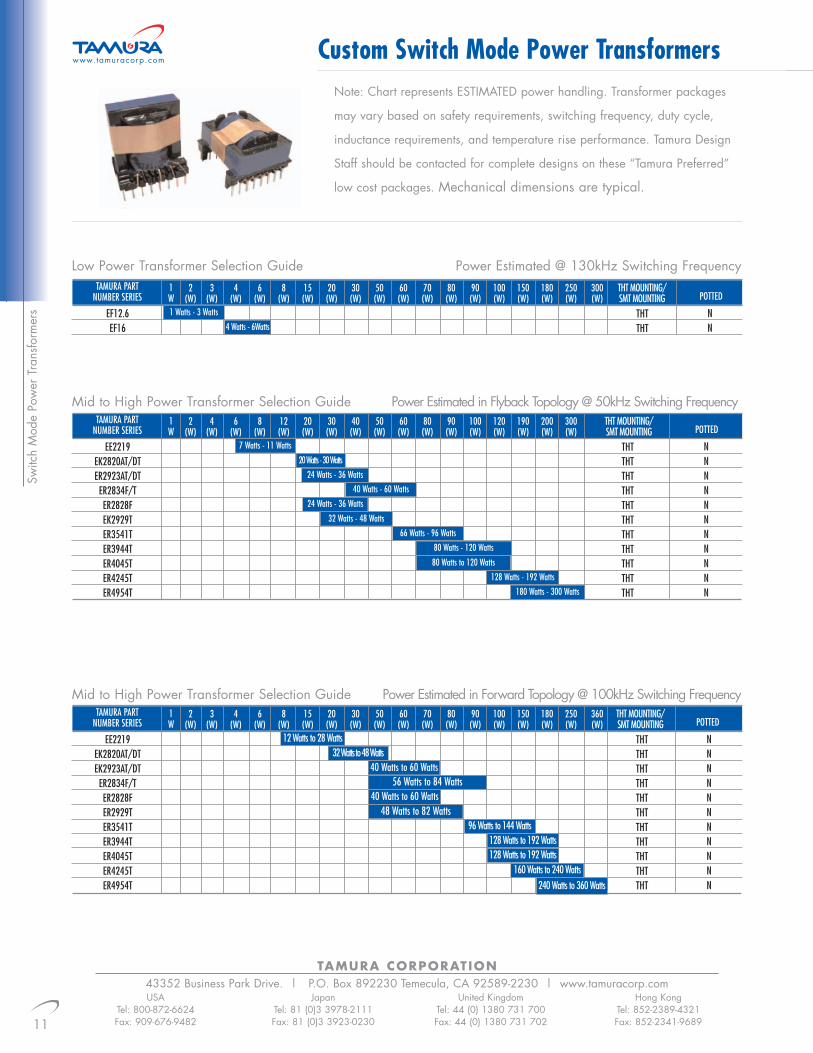
Note: Chart represents ESTIMATED power handling. Transformer packages
may vary based on safety requirements, switching frequency, duty cycle,
inductance requirements, and temperature rise performance. Tamura Design
Staff should be contacted for complete designs on these “Tamura Preferred”
low cost packages. Mechanical dimensions are typical.
www.tamuracorp.com
Low Power Transformer Selection Guide Power Estimated @ 130kHz Switching FrequencyTAMURA PART
NUMBER SERIES2 3 4 6 8 15 20 30 50 60 70 80 90 100 150 180 250 300 THT MOUNTING/
POTTED(W) (W) (W) (W) (W) (W) (W) (W) (W) (W) (W) (W) (W) (W) (W) (W) (W) (W) SMT MOUNTINGEF12.6EF16
THTTHT
NN
1 Watts - 3 Watts
4 Watts - 6Watts
1W
Mid to High Power Transformer Selection Guide Power Estimated in Forward Topology @ 100kHz Switching FrequencyTAMURA PART
NUMBER SERIES2 3 4 6 8 15 20 30 50 60 70 80 90 100 150 180 250 360 THT MOUNTING/
POTTED(W) (W) (W) (W) (W) (W) (W) (W) (W) (W) (W) (W) (W) (W) (W) (W) (W) (W) SMT MOUNTINGEE2219
EK2820AT/DTEK2923AT/DT
ER2834F/TER2828FER2929TER3541TER3944TER4045TER4245TER4954T
THTTHTTHTTHTTHTTHTTHTTHTTHTTHTTHT
NNNNNNNNNNN
12 Watts to 28 Watts32 Watts to 48 Watts
40 Watts to 60 Watts56 Watts to 84 Watts
40 Watts to 60 Watts48 Watts to 82 Watts
96 Watts to 144 Watts128 Watts to 192 Watts128 Watts to 192 Watts
160 Watts to 240 Watts240 Watts to 360 Watts
1W
Mid to High Power Transformer Selection Guide Power Estimated in Flyback Topology @ 50kHz Switching FrequencyTAMURA PART
NUMBER SERIES2 4 6 8 12 20 30 40 50 60 80 90 100 120 190 200 300 THT MOUNTING/
POTTED(W) (W) (W) (W) (W) (W) (W) (W) (W) (W) (W) (W) (W) (W) (W) (W) (W) SMT MOUNTINGEE2219
EK2820AT/DTER2923AT/DT
ER2834F/TER2828FEK2929TER3541TER3944TER4045TER4245TER4954T
THTTHTTHTTHTTHTTHTTHTTHTTHTTHTTHT
NNNNNNNNNNN
7 Watts - 11 Watts
20 Watts - 30 Watts
24 Watts - 36 Watts40 Watts - 60 Watts
24 Watts - 36 Watts
32 Watts - 48 Watts
66 Watts - 96 Watts
80 Watts - 120 Watts
80 Watts to 120 Watts
128 Watts - 192 Watts
180 Watts - 300 Watts
1W

12
TAMURA CORPORATION43352 Business Park Drive. | P.O. Box 892230 Temecula, CA 92589-2230 | www.tamuracorp.comUSA
Tel: 800-872-6624Fax: 909-676-9482
JapanTel: 81 (0)3 3978-2111Fax: 81 (0)3 3923-0230
United KingdomTel: 44 (0) 1380 731 700Fax: 44 (0) 1380 731 702
Hong KongTel: 852-2389-4321Fax: 852-2341-9689
Custom Switch Mode Power Transformers www.tamuracorp.com
Switch M
ode Power Transform
ers
EF12.6
EE2219
EK2820DT EK2923AT
EK2820AT
EF16
EK2923DT ER2834F

TAMURA CORPORATION43352 Business Park Drive. | P.O. Box 892230 Temecula, CA 92589-2230 | www.tamuracorp.com
13
Custom Switch Mode Power Transformers
USATel: 800-872-6624Fax: 909-676-9482
JapanTel: 81 (0)3 3978-2111Fax: 81 (0)3 3923-0230
United KingdomTel: 44 (0) 1380 731 700Fax: 44 (0) 1380 731 702
Hong KongTel: 852-2389-4321Fax: 852-2341-9689
www.tamuracorp.com
Switc
h M
ode
Pow
er T
rans
form
ers
ER2834T ER2828
ER3541T EK2929T
ER4045T ER4245T
ER3944T ER4954T
14
TAMURA CORPORATION43352 Business Park Drive. | P.O. Box 892230 Temecula, CA 92589-2230 | www.tamuracorp.comUSA
Tel: 800-872-6624Fax: 909-676-9482
JapanTel: 81 (0)3 3978-2111Fax: 81 (0)3 3923-0230
United KingdomTel: 44 (0) 1380 731 700Fax: 44 (0) 1380 731 702
Hong KongTel: 852-2389-4321Fax: 852-2341-9689
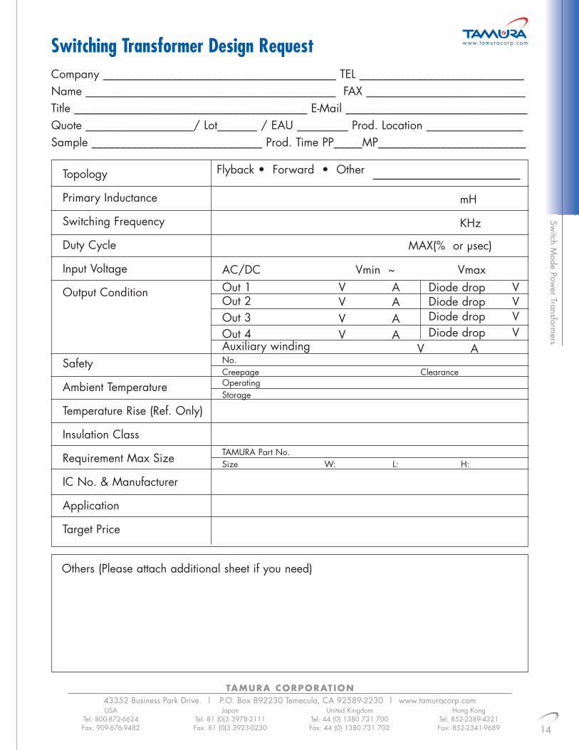
www.tamuracorp.comSwitching Transformer Design RequestSw
itch Mode Pow
er Transformers
Company _________________________________________ TEL _____________________________Name ____________________________________________ FAX ____________________________Title _________________________________________ E-Mail ________________________________Quote ___________________/ Lot_______ / EAU _________ Prod. Location _________________Sample ______________________________ Prod. Time PP_____MP__________________________
Topology
Primary Inductance
Switching Frequency
Duty Cycle
Input Voltage
Output Condition
Safety
Ambient Temperature
Temperature Rise (Ref. Only)
Insulation Class
Requirement Max Size
IC No. & Manufacturer
Application
Target Price
Others (Please attach additional sheet if you need)
Flyback • Forward • Other
mH
KHz
MAX(% or µsec)
AC/DCOut 1 V AOut 2 V AOut 3 V AOut 4Auxiliary windingNo.Creepage Clearance
V A
Diode drop VDiode drop VDiode drop VDiode drop V
V A
Vmin ~ Vmax
OperatingStorage
TAMURA Part No.Size W: L: H:

TTC-50231 600:600 0 2.0 -79 80 16TTC-5024 600:330 0 3.0 -85 80 27TTC-5025 600:430 0 3.5 -79 80 20TTC-5032 600:470 0 2.5 -79 80 27TTC-5035 600:346 0 3.0 -84 80 27TTC-5036 600:287 0 4.0 -90 80 27TTC-5037 600:560 0 2.0 -77 80 23
Tele
com
Tra
nsfo
rmer
s
TAMURA CORPORATION43352 Business Park Drive. | P.O. Box 892230 Temecula, CA 92589-2230 | www.tamuracorp.com
15
Voice/Modem Line Transformers
USATel: 800-872-6624Fax: 909-676-9482
JapanTel: 81 (0)3 3978-2111Fax: 81 (0)3 3923-0230
United KingdomTel: 44 (0) 1380 731 700Fax: 44 (0) 1380 731 702
Hong KongTel: 852-2389-4321Fax: 852-2341-9689
Mechanical Dimensions mm (inches)All dimensions are typical, please contact Tamura for tolerances and suggested layout information.
Schematics
www.tamuracorp.com
V.29, V.32, V.34, V.90, & V.92 Applications• Highest Density Package Available• Approved to UL1950 3rd Edition• Approved to UL60950 & EN60950• Surface Mount• Vacuum Encapsulated• Pri:Sec Hi-Pot=1500Vrms and Higher• Surge Voltage
Return Loss @ 1KHz(dB Typ)
Long.Balance
(dB MIN.)
Total HarmonicDistortion(dB Typ.)
InsertionLoss
(dB MAX.)
DCUnbalance
(mA)
ImpedancePRI:SEC
(Ω)Part #
TTC-5027 30k:30k 0 30.0 110TTC-5033 10k:10k 0 6.5 22TTC-5034 20k:20k 0 18.0 60
Shunt Loss Rp @ 200Hz10mVrms (Ω MIN)
Inductance Lp @ 200Hz10mVrms (H MIN)
DCUnbalance
(mA)
ImpedancePRI:SEC
(Ω)Part #
L:12.5 (0.49) W:9.60 (0.38) H:7.6 (0.30)
1 3000 Vrms Pri:Sec Hi-Pot
43
1 6
High Impedance Applications
PRI SEC
Electrical Specification @ Ta=25˚C
Package Information
50 400
QTY/Tray Tape/Reel

Telecom Transform
ers
Mechanical Dimensions mm (inches)
Schematics
Voice/Modem Line Transformers www.tamuracorp.com
All dimensions are typical, please contact Tamura fortolerances and suggested layout information.
V.29, V.32 & V.34 Applications • Approved to UL1950 3rd Edition
• Approved to UL60950 & EN60950
• Hi-Pot 1500Vrms Pri:Sec
3132
1 4 1 6
5
43
2
1 4
2 3
Fig. B
L:23.1 (0.909) W:22.5 (0.885) H:13.8 (0.54)
L W
H
13.80 (0.54)11.40 (0.45)
Fig. C
L:15.0 (0.591) W:14.5 (0.571) H:12.0 (0.472)
LW
H
10.16 (0.4) 10.16 (0.4)
Fig. A
L:24.8 (0.98) W:23.6 (0.93) H:13.8 (0.54)
L W
H
13.80 (0.54)11.40 (0.45)
PRI SECPRI SECPRI SEC
TAMURA CORPORATION 43352 Business Park Drive. | P.O. Box 892230 Temecula, CA 92589-2230 | www.tamuracorp.com
16
USATel: 800-872-6624Fax: 909-676-9482
JapanTel: 81 (0)3 3978-2111Fax: 81 (0)3 3923-0230
United KingdomTel: 44 (0) 1380 731 700Fax: 44 (0) 1380 731 702
Hong KongTel: 852-2389-4321Fax: 852-2341-9689
1 3000 Vrms Pri:Sec Hi-Pot
Electrical Specification @ Ta=25°C
Part #ImpedancePRI: SEC
(Ω)
DCUnbalance
(mA)
InsertionLoss
(dB MAX)
Total Harmonic Distortion(dB Typ)
Long.Balance(dB MIN)
Return Loss @1 KHz
(dB Typ)Mounting Package
Fig.Schematic
Fig.
TTC-5019 600:260 50 4.0 -60 60 _ THD B 1
TTC-50101 600:301 65 3.75 -50 60 _ THD (CASE) A 2
TTC-5020 600:301 65 3.75 -50 60 _ THD B 2
TTC-264M1 600:470 100 2.5 -50 60 _ THD (CASE) A 1
TTC-5028 600:470 100 2.5 -50 60 _ THD B 1

TAMURA CORPORATION43352 Business Park Drive. | P.O. Box 892230 Temecula, CA 92589-2230 | www.tamuracorp.com
17
High Speed Modem Transformers
USATel: 800-872-6624Fax: 909-676-9482
JapanTel: 81 (0)3 3978-2111Fax: 81 (0)3 3923-0230
United KingdomTel: 44 (0) 1380 731 700Fax: 44 (0) 1380 731 702
Hong KongTel: 852-2389-4321Fax: 852-2341-9689
www.tamuracorp.com
Tele
com
Tra
nsfo
rmer
s
V.90, V.92 Applications• Optimized for High Speed Modem Applications• Frequency Range 300Hz to 4kHz• 1500 Vrms Hi-Pot (Pri:Sec)• Approved to UL1950 3rd Edition• PCMCIA Packages• Approved to UL60950 & EN60950
Mechanical Dimensions mm (inches)
PackageFig.
SchematicFig.MountingReturn Loss @ 1KHz
(dB Typ)Long.
Balance(dB MIN.)
Total HarmonicDistortion(dB Typ.)
InsertionLoss
(dB MAX.)
DCUnbalance
(mA)
ImpedancePRI:SEC
(Ω)Part #
TTC-511 600:287 0 3.85 -82 60 35 SMD A 1TTC-5021 600:287 0 3.85 -82 60 33 SMD F 1TTC-5000 600:301 0 3.25 -92 60 26 THD D 4TTC-50011 600:301 0 3.25 -92 60 26 THD (CASE) C 4TTC-5013 600:301 65 4.00 -89 60 15 THD D 4TTC-5003 600:320 0 3.20 -92 60 29 SMD I 6TTC-5014 600:348 0 3.25 -88 60 30 THD H 5TTC-50061 600:374 0 2.5 -90 60 29 THD (CASE) C 4TTC-5008 600:374 0 2.5 -90 60 29 THD D 4TTC-5022 600:374 0 2.3 -89 60 30 THD E 1TTC-5004 600:392 0 2.2 -89 60 33 SMD I 6TTC-5015 600:442 0 2.0 -85 60 35 THD H 5TTC-5026 600:490 0 1.5 -80 60 28 SMD I 3TTC-512 600:510 0 1.50 -75 60 30 SMD B 2
TTC-5005 600:525 0 1.6 -86 60 27 SMD I 6TTC-50071 600:530 0 1.0 -83 60 32 THD (CASE) C 4TTC-5009 600:530 0 1.0 -83 60 32 THD D 4TTC-5016 600:560 0 1.5 -82 60 23 THD H 5TTC-50121 600:600 0 1.0 -76 60 31 THD (CASE) C 4TTC-5017 600:600 0 1.5 -82 60 23 THD H 4TTC-5018 600:600 0 1.0 -76 60 31 THD D 4TTC-5029 600:600 0 1.0 -88 60 25 THD G 5
Fig. C
Fig. D
L: 9.9 (0.39) W :17.8 (0.70) H: 4.9 (0.19) L: 9.9 (0.39) W :16.9 (0.66) H: 4.9 (0.19) L: 24.8 (0.98) W:23.6 (0.93) H:13.80 (0.54)
L:23.1 (0.9) W:22.5 (0.89) H:13.8 (0.54)
Fig. E
L:24.0 (0.94) W:26.0 (1.02) H:13.8 (0.54)
Fig. A Fig. B
All dimensions are typical, please contact Tamura for tolerances and suggested layout information.
1 3000 Vrms Pri:Sec Hi-Pot
H
H H
H
H
L
L L
LLW
W W
W W
20.6 (0.81) 20.6 (0.81)
5.08 (0.20)5.08 (0.20)
11.40 (0.45)
11.40 (0.45) 11.40 (0.45)
13.80 (0.54)
13.80 (0.54) 13.80 (0.54)
Electrical Specification @ Ta=25˚C

18
TAMURA CORPORATION43352 Business Park Drive. | P.O. Box 892230 Temecula, CA 92589-2230 | www.tamuracorp.comUSA
Tel: 800-872-6624Fax: 909-676-9482
JapanTel: 81 (0)3 3978-2111Fax: 81 (0)3 3923-0230
United KingdomTel: 44 (0) 1380 731 700Fax: 44 (0) 1380 731 702
Hong KongTel: 852-2389-4321Fax: 852-2341-9689
High Speed Modem Transformers www.tamuracorp.com
Telecom Transform
ers
Mechanical Dimensions mm (inches)All dimensions are typical, please contact Tamura for tolerances and suggested layout information.
Schematics
365
11
482
10
PRI SEC
432
1 4
PRI SEC
543
1 6
PRI SEC
674
1 10
PRI SEC
132
1 4
PRI SEC
232
1 4
PRI SEC
L:13.5 (0.53) W:14.0 (0.55) H:10.4 (0.41)L:15.0 (0.59) W:14.5 (0.57) H:12.0 (0.47)
Fig. IFig. H
L:17.0 (0.67) W:17.0 (0.67) H:12.0 (0.47)
Fig. G
L: 8.5 (0.35) W: 16.3 (0.64) H: 5.1 (0.20)
Fig. F
L L L LH
H H
WW W
W
5.08 (0.2)7.62 (0.3) 10.16 (0.4) 2.54 (0.1)
18.5 (0.728)
10.16 (0.4)12.50 (0.492)
20.90 (0.823)
H

TAMURA CORPORATION43352 Business Park Drive. | P.O. Box 892230 Temecula, CA 92589-2230 | www.tamuracorp.com
19
USATel: 800-872-6624Fax: 909-676-9482
JapanTel: 81 (0)3 3978-2111Fax: 81 (0)3 3923-0230
United KingdomTel: 44 (0) 1380 731 700Fax: 44 (0) 1380 731 702
Hong KongTel: 852-2389-4321Fax: 852-2341-9689
www.tamuracorp.com
Tele
com
Tra
nsfo
rmer
sDAA Modem Line Transformers
• Highest Density Packages Available
• IC Grade Transfer Molding
• PCMCIA Height Packages
• Surge Voltage
• Approved to UL1950 3rd Edition
• High Reliability
Fig. B
L:6.9 (0.272) W:4.7 (0.185) H:2.05 (0.081)
Fig. C
L:9.91 (0.38) W:9.91 (0.39) H:2.49 (0.098)
Mechanical Dimensions mm (inches)
Schematics
SchematicFig.
PackageFig.Mounting
HiPot(Vrms)
DCR(Ω) Min
PRI
OCL(µH) MIn
PRITurns RatioTAMURA Part
1
32
1 4
PRI SEC
2
54
1 8
PRI SEC
All dimensions are typical, please contact Tamurafor tolerances and suggested layout information.
TTC-313 1:2.6 2.3 0.15 2500 8 Pin PCMCIA A 2
TTC-317 1:2.4 40 0.275 2500 8 Pin PCMCIA A 2
TTC-319 1:1.5 30 0.225 3000 4 PIN PCMCIA B 1
TTC-320 1:2.6 40 0.15 1300 8 Pin PCMCIA A 2
TTC-323 1:2 30 0.225 1650 4 Pin PCMCIA B 1
TTC-338 1:1.67 40 0.15 3750 4 Pin PCMCIA C 2
TTC-331 1:1.67 30 0.225 3000 4 Pin PCMCIA B 1
Fig. A
L:9.91 (0.39) W:9.91 (0.39) H:2.49 (0.098)
L L L
H H
H
W W W
2.54 (0.10)7.62 (0.3)
12.45 (0.49)
Electrical Specification @ Ta=25˚C
20
TAMURA CORPORATION43352 Business Park Drive. | P.O. Box 892230 Temecula, CA 92589-2230 | www.tamuracorp.comUSA
Tel: 800-872-6624Fax: 909-676-9482
JapanTel: 81 (0)3 3978-2111Fax: 81 (0)3 3923-0230
United KingdomTel: 44 (0) 1380 731 700Fax: 44 (0) 1380 731 702
Hong KongTel: 852-2389-4321Fax: 852-2341-9689
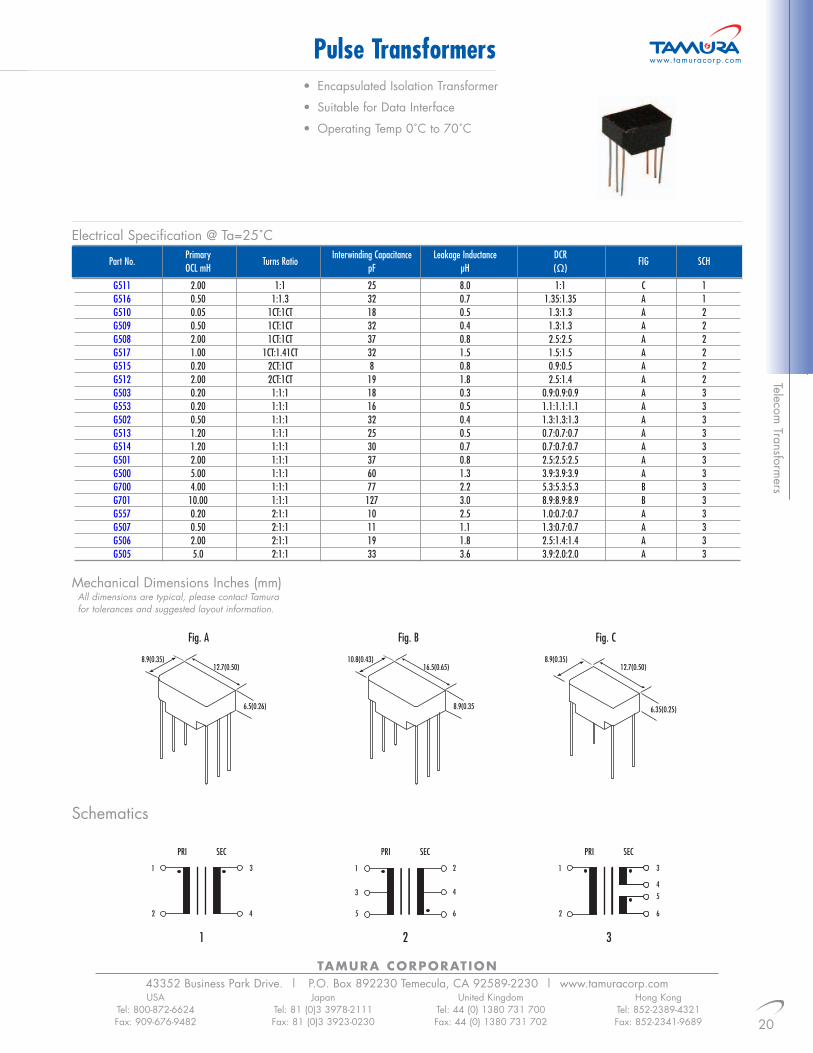
Pulse Transformers• Encapsulated Isolation Transformer
• Suitable for Data Interface
• Operating Temp 0˚C to 70˚C
www.tamuracorp.com
1
42
1 3
PRI SEC
2
65
1
3
2
4
PRI SEC
3
62
1 3
45
PRI SEC
Mechanical Dimensions Inches (mm)All dimensions are typical, please contact Tamurafor tolerances and suggested layout information.
Telecom Transform
ers
Part No.Primary
Turns RatioInterwinding Capacitance Leakage Inductance DCR
FIG SCHOCL mH pF µH (Ω)
G511 2.00 1:1 25 8.0 1:1 C 1G516 0.50 1:1.3 32 0.7 1.35:1.35 A 1G510 0.05 1CT:1CT 18 0.5 1.3:1.3 A 2G509 0.50 1CT:1CT 32 0.4 1.3:1.3 A 2G508 2.00 1CT:1CT 37 0.8 2.5:2.5 A 2G517 1.00 1CT:1.41CT 32 1.5 1.5:1.5 A 2G515 0.20 2CT:1CT 8 0.8 0.9:0.5 A 2G512 2.00 2CT:1CT 19 1.8 2.5:1.4 A 2G503 0.20 1:1:1 18 0.3 0.9:0.9:0.9 A 3G553 0.20 1:1:1 16 0.5 1.1:1.1:1.1 A 3G502 0.50 1:1:1 32 0.4 1.3:1.3:1.3 A 3G513 1.20 1:1:1 25 0.5 0.7:0.7:0.7 A 3G514 1.20 1:1:1 30 0.7 0.7:0.7:0.7 A 3G501 2.00 1:1:1 37 0.8 2.5:2.5:2.5 A 3G500 5.00 1:1:1 60 1.3 3.9:3.9:3.9 A 3G700 4.00 1:1:1 77 2.2 5.3:5.3:5.3 B 3G701 10.00 1:1:1 127 3.0 8.9:8.9:8.9 B 3G557 0.20 2:1:1 10 2.5 1.0:0.7:0.7 A 3G507 0.50 2:1:1 11 1.1 1.3:0.7:0.7 A 3G506 2.00 2:1:1 19 1.8 2.5:1.4:1.4 A 3G505 5.0 2:1:1 33 3.6 3.9:2.0:2.0 A 3
8.9(0.35)12.7(0.50)
6.5(0.26)
Fig. A
Schematics
10.8(0.43)16.5(0.65)
8.9(0.35
Fig. B
8.9(0.35)12.7(0.50)
6.35(0.25)
Fig. C
Electrical Specification @ Ta=25˚C

TAMURA CORPORATION43352 Business Park Drive. | P.O. Box 892230 Temecula, CA 92589-2230 | www.tamuracorp.com
21
ADSL PRODUCT SELECTION GUIDE
USATel: 800-872-6624Fax: 909-676-9482
JapanTel: 81 (0)3 3978-2111Fax: 81 (0)3 3923-0230
United KingdomTel: 44 (0) 1380 731 700Fax: 44 (0) 1380 731 702
Hong KongTel: 852-2389-4321Fax: 852-2341-9689
See www.tamuracorp.com for detail specifications
• Designed for lowest THD
• 1500Vrms Hi-Pot
• UL1950, UL60950 and EN609540 approvals
• Extended Temperature Designs
• Call Tamura for Professional Custom Designs
www.tamuracorp.com
Tele
com
Tra
nsfo
rmer
s
Mechanical Dimensions
Fig. B
Fig. A
L:14.0 (0.55) W:14.0 (0.55) H:13.5 (0.53)
L:14.0 (0.55) W:14.0 (0.55) H:12.7 (0.50)
Fig. C
L:9.90 (0.40) W:8.80 (0.35) H:12.3 (0.50)
CHIPLINE
Turns RatioCHIP:LINE
SchematicFig.
PackageFig.
LeakageInductance
(µH)
DCR (Ω MAX.)Inductance@ 10KHz,
0.1VMountingApplicationPart #IC NumberIC
Manufacturer
MTK-20140 TTC-432 CPE THD 1:1 480µH 1 1 10 A 1MTK-20141 TTC-432SL CPE SMD 1:1 480µH 1 1 10 B 1
MTK-20140TTC-433 CO THD 1:2 410µH 0.6 0.3 6.5 A 1
ALCATEL TTC-433SL CO SMD 1:2 410µH 0.6 0.3 6.5 B 1MTK-20156MTK-20164
TTC-4082 CPE SMD 1:2 409.5µH 1.4 0.7 6.5 B 5
MTK-20450 TTC-4113 CO SMT 1:1.41 450µH 1.4 1.4 8 B 1AD20MSP910 TTC-4014 CO/CPE THD 1:1 5mH 3 3 16 A 1AD20MSP918 TTC-4015 CO/CPE SMD 1:1 5mH 3 3 16 B 1
ANALOG TTC-435 CO/CPE THD 1:1.1 1.8mH 2 2 7.5 A 2DEVICE TTC-435SL CO/CPE SMD 1:1.1 1.8mH 2 2 7.5 B 2
AD20MSP930TTC-7005 ADSL over ISDN SMD 1:1 100µH 1 1 4 B 1TTC-7006 ADSL over ISDN SMD 1:1.2 120µH 1 1 4 B 1
EAGLE ANALOGRECEIVE
TTC-4134 CPE SMT 1.4:1 400µH 0.99 1.38 10 B 2
EAGLE ANALOGTRANSMIT
TTC-4135 CPE SMT 1:3 1.22mH 1 0.35 14 B 2
CT-L21SC04 TTC-4048 CO SMD 1:1 440µH 1 1 5 B 1
CT-L22SU15TTC-4049 CPE SMD 1:1 5mH 3 3 18 B 1TTC-4802 CPE THD 1:1 5mH 3 3 18 A 1
CT-L41SC08TTC-4801 CO THD 1:1 441.5µH 0.8 0.6 5 A 1TTC-4803 CO SMD 1:1 441.5µH 0.8 0.6 5 B 1
CT-L50SC04 TTC-4050 CO SMD 1:1.8 450µH 1.0 0.6 5.5 B 1CENTILLIUM TTC-4814 CPE THD 1:2.125 5mH 0.75 3.5 12 A 1
CT-L52DU81TTC-4058 CPE SMD 1:2.125 5mH 0.75 3.5 12 B 1
CT-L53SC08CT-L76SC08
TTC-4088 CO SMD 1:1 850µH 2.2 3.0 6.0 C 6
CT-L21DT01TTC-4099 CPE THT 1:1 455µH 0.8 0.6 5.0 A 1
CT-L10AT01CT-L73SC08 TTC-4103 CO SMD 1:2 1.0mH 1.6 0.55 5.5 B 1PALLADIA
200/210/22TTC-4117 CPE SMT 1:2.5 5mH 3.8 1 15 B 2
PALLADIA200/210/22
TTC-4118 CPE SMT 1:1 5mH 3.2 3.6 15 B 2
CONEXANT20441 TTC-4016
CO/CPETHD 1:2 0.8mH 1.48 0.77 10 A 33000Vrms
CN9001 TTC-4017 CO/CPE SMD 1:2 0.8mH 1.48 0.77 10 B 4
Schematics
41 2 3 5 6
10.16 (0.4)
2.5 (0.1)
2.5 (0.1)
2.54 (0.1)
H
H
H
W
W
W
L
L
L
17.8 (0.69)
Electrical Specification @ Ta=25˚C

22
TAMURA CORPORATION43352 Business Park Drive. | P.O. Box 892230 Temecula, CA 92589-2230 | www.tamuracorp.comUSA
Tel: 800-872-6624Fax: 909-676-9482
JapanTel: 81 (0)3 3978-2111Fax: 81 (0)3 3923-0230
United KingdomTel: 44 (0) 1380 731 700Fax: 44 (0) 1380 731 702
Hong KongTel: 852-2389-4321Fax: 852-2341-9689
ADSL PRODUCT SELECTION GUIDESee www.tamuracorp.com for detail specifications
• Designed for lowest THD
• 1500Vrms Hi-Pot
• UL1950, UL60950 and EN609540 approvals
• Extended Temperature Designs
• Call Tamura for Professional Custom Designs
www.tamuracorp.com
Mechanical Dimensions
Schematics
CHIPLINE
Turns RatioCHIP:LINE
SchematicFig.
PackageFig.
LeakageInductance
(µH)
DCR (Ω MAX.)Inductance@ 10KHz,
0.1VMountingApplicationPart #IC NumberIC
Manufacturer
G7000 TTC-4059 CPE SMD 1:1 430 µH 0.9 0.7 10 B 3G7266 TTC-4060 CO SMD 1:1.4 441 µH 1.0 0.8 10 B 4
GLOBESPANEL1501 TTC-4064 CPE THD 1:1 407.5 µH 1.4 1.2 10 A 1
TTC-4081 CPE SMD 1:2 100 µH 1.0 0.5 12 B 2TTC-40852 CO SMD 1:1.41 475 µH 2.9 2.9 15 C 6
G7070TTC-4105 CPE SMD 1:2 440 µH 1.6 0.8 10 B 4TTC-41091 CO SMD 1:2 530 µH 1.5 0.4 15 D 7
ATLAS TTC-4116 CPE SMT 1:1.6 440µH 2.3 1.5 11 B 4
ITEX APOLLO 2TTC-4051 CPE THD 1:1 440µH 1.0 1.0 10 A 1TTC-4052 CPE SMD 1:1 440 µH 1.0 1.0 10 B 1
SILICONSI-3101 TTC-4138 SMT 3mH 2.64 0.19/0.83 15 F 8SI-3101 TTC-4139 THT 3mH 2.64 0.19/0.83 15 A 8
TNETD2000R TTC-4054 CPE THD 1:1.42 1.5mH 4.0 0.7 18 A 5TNETD3000P
TTC-4055 CPE SMD 1:1.42 1.5mH 4.0 0.7 18 B 5
TITNETD4000R
TNETD4000CTTC-4053 CO THD 1:2 75µH 2.0 0.55 12 A 5TTC-4071 CPE SMD 1:2 75µH 2.0 0.55 12 B 5
TNETD5000P TTC-4069 CPE THD 1:1.95 1.5mH 2.0 0.55 15 A 5
AC5TTC-4101 CO SMD 1:1.9 400µH 1.0 1.0 7.5 E 6TTC-4124 CO SMT 1:1.9 400µH 1.0 1.0 5 E 6
5
21 3 4
Fig. C
Fig. B
Fig. A
6 87
L:14.0 (0.55) W:14.0 (0.55) H:13.5 (0.53)
L:14.0 (0.55) W:14.0 (0.55) H:12.7 (0.50)
Fig. D
L:10.3 (0.41) W:11.0 (0.43) H:9.27 (0.36)
Fig. E
L:15.2 (0.60) W:12.45 (0.50) H:11.4 (0.45)
Fig. F
L:14.0 (0.55) W:14.0 (0.55) H:13.5 (0.532)
L:9.90 (0.40) W:8.80 (0.35) H:12.3 (0.50)
1:4.25 1:2.5
1:4.25 1:2.5
1 Designed to meet UL14592 Approvals Pending
Telecom Transform
ers
Electrical Specification @ Ta=25˚C
2.5(0.098)
17.0(0.669)

TAMURA CORPORATION43352 Business Park Drive. | P.O. Box 892230 Temecula, CA 92589-2230 | www.tamuracorp.com
23
HDSL / HDSL2 / SDSL / G.SHDSL
USATel: 800-872-6624Fax: 909-676-9482
JapanTel: 81 (0)3 3978-2111Fax: 81 (0)3 3923-0230
United KingdomTel: 44 (0) 1380 731 700Fax: 44 (0) 1380 731 702
Hong KongTel: 852-2389-4321Fax: 852-2341-9689
See www.tamuracorp.com for detail specifications• HiPot 1500Vrms
• Operating Temp -40 to +85˚C
• Approved to UL1950 3rd Edition, EN60950 / IEC950
www.tamuracorp.com
Tele
com
Tra
nsfo
rmer
s
Schematics
CHIPLINE
Turns RatioCHIP:LINE
SchematicFig.
PackageFig.
LeakageInductance
(µH)
DCR (Ω MAX.)Inductance@ 10KHz,0.1V (mH)
MountingApplicationPart #IC NumberICManufacturer
BT8970 TTC-4018 2320Kbps THD 1:1:1 1 1.9 0.85 11 A 1TTC-4019 2320Kbps SMD 1:1:1 1 1.9 0.95 11 B 1
CONEXANT RS8973 TTC-4062 ALL SMD 1:1:1 2 3.2 1.15 6.5 B 1CN8980 TTC-4056 ALL THD 1:5 2 0.57 0.25 0.5 A 1RS8973 TTC-4093 HDSL THD 1:2 2 3.2 1.2 6.5 A 1
TTC-4063 ALL SMD 1:2.2 3 2.5 1.1 10 B 3TTC-4074 G.SHDSL SMD 1:4 2 2.5 1.0 11 B 1TTC-4083 G.SHDSL SMD 1:5.4 3 2.2 0.2 12 B 1
GLOBESPAN G2237 SHDSLTTC-4115 HDSL2 SMT 1:5.4 3mH 4.2 0.35 15 B 1
HDSL4INFINEON PEB22622 TTC-4070 ALL SMD 1:1:3.2 3 4.5 2.1 33 B 4
PEB22622PEF22623 TTC-4123 SHDSL SMT 1:3.2 3mH 4.3 2 25 B 2PEF24622
SK70704/07 TTC-4036 1168Kbps SMD 1:1.8CTS 0.6 7 3.17 20 B 1LEVEL ONE 784Kbps
SK70706/21400Kbps
SK70740/41/42TTC-4084 HDSL2 SMD 1:2.3 2 3.8 0.9 35 B 5TTC-4089 HDSL SMD 1:2 2.0 2.5 1.4 10 B 6
Mechanical Dimensions
Fig. B
Fig. A
L:14.0 (0.55) W:14.0 (0.55) H:13.5 (0.53)
L:14.0 (0.55) W:14.0 (0.55) H:12.7 (0.50)
4 5 6
1 2 3
10.16 (0.4)
10.16 (0.4)
2.54 (0.1)
2.54 (0.1)
H
H
W
W
L
L
Electrical Specification @ Ta=25˚C

24
TAMURA CORPORATION43352 Business Park Drive. | P.O. Box 892230 Temecula, CA 92589-2230 | www.tamuracorp.comUSA
Tel: 800-872-6624Fax: 909-676-9482
JapanTel: 81 (0)3 3978-2111Fax: 81 (0)3 3923-0230
United KingdomTel: 44 (0) 1380 731 700Fax: 44 (0) 1380 731 702
Hong KongTel: 852-2389-4321Fax: 852-2341-9689
Power Line Control Transformers www.tamuracorp.com
Telecom Transform
ers
Schematics
For use with Echelon’s PLT-22 Transceiver• Designed to Meet UL60950
• HiPot = 3000Vrms (Pri:Sec)
SchematicFig.
PackageFig.
DCR (Ω)
PRI (3-1) SEC (4-6)Interwinding Capacitance (pF)
@ 100kHzLeakage Inductance
(µH) @ 100kHz
Primary Inductance (mH)@ 100kHz
DRY WET (15mADC)
Turns Ratio(PRI:SEC)
TAMURA Part #
PLP011 1:1 1.0 0.75 12 30 0.2 0.2 A 1PLOPUE 1:1 1.0 0.75 12 30 0.2 0.2 A 1
Mechanical Dimensions
Fig. A
L: 20.0 (0.787) W: 21.0 (0.827) H: 16.5 (0.649)
H
LW
1
2
3
1
5
4
6
PRI SEC
1 Designed to Meet UL 1950
Electrical Specification @ Ta=25˚C
TAMURA CORPORATION43352 Business Park Drive. | P.O. Box 892230 Temecula, CA 92589-2230 | www.tamuracorp.com
25
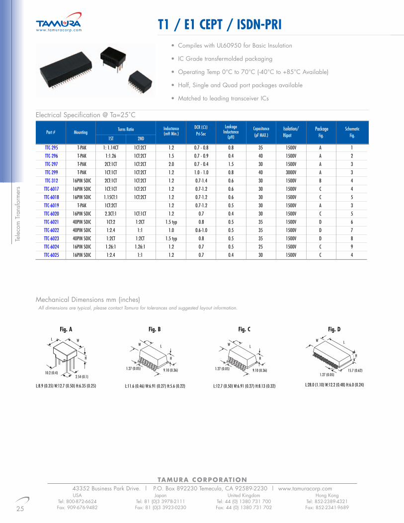
T1 / E1 CEPT / ISDN-PRI
USATel: 800-872-6624Fax: 909-676-9482
JapanTel: 81 (0)3 3978-2111Fax: 81 (0)3 3923-0230
United KingdomTel: 44 (0) 1380 731 700Fax: 44 (0) 1380 731 702
Hong KongTel: 852-2389-4321Fax: 852-2341-9689
• Compiles with UL60950 for Basic Insulation
• IC Grade transfermolded packaging
• Operating Temp 0°C to 70°C (-40°C to +85°C Available)
• Half, Single and Quad port packages available
• Matched to leading transceiver ICs
www.tamuracorp.com
Tele
com
Tra
nsfo
rmer
s
Fig. A
LeakageInductance
(µH)
SchematicFig.
PackageFig.
Capacitance(pF MAX.)
DCR (Ω)Pri-Sec
Inductance(mH Min.)
Turns Ratio
1ST 2NDMountingPart #
Isolation/Hipot
TTC-295 T-PAK 1: 1.14CT 1CT:2CT 1.2 0.7 - 0.8 0.8 35 1500V A 1
TTC-296 T-PAK 1:1.26 1CT:2CT 1.5 0.7 - 0.9 0.4 40 1500V A 2
TTC-297 T-PAK 2CT:1CT 1CT:2CT 2.0 0.7 - 0.4 1.5 30 1500V A 3
TTC-299 T-PAK 1CT:1CT 1CT:2CT 1.2 1.0 - 1.0 0.8 40 3000V A 3
TTC-312 16PIN SOIC 2CT:1CT 1CT:2CT 1.2 0.7-1.4 0.6 30 1500V B 4
TTC-6017 16PIN SOIC 1CT:1CT 1CT:2CT 1.2 0.7-1.2 0.6 30 1500V C 4
TTC-6018 16PIN SOIC 1.15CT:1 1CT:2CT 1.2 0.7-1.2 0.6 30 1500V C 5
TTC-6019 T-PAK 1CT:2CT 1.2 0.7-1.2 0.5 30 1500V A 3
TTC-6020 16PIN SOIC 2.3CT:1 1CT:1CT 1.2 0.7 0.4 30 1500V C 5
TTC-6021 40PIN SOIC 1CT:2 1:2CT 1.5 typ 0.8 0.5 35 1500V D 6
TTC-6022 40PIN SOIC 1:2.4 1:1 1.0 0.6-1.0 0.5 35 1500V D 7
TTC-6023 40PIN SOIC 1:2CT 1:2CT 1.5 typ 0.8 0.5 35 1500V D 8
TTC-6024 16PIN SOIC 1.26:1 1.26:1 1.2 0.7 0.5 25 1500V C 9
TTC-6025 16PIN SOIC 1:2.4 1:1 1.2 0.7 0.4 30 1500V C 4
Fig. B
L:11.6 (0.46) W:6.91 (0.27) H:5.6 (0.22)
Fig. C
L:12.7 (0.50) W:6.91 (0.27) H:8.13 (0.32)L:8.9 (0.35) W:12.7 (0.50) H:6.35 (0.25)
Fig. D
L:28.0 (1.10) W:12.2 (0.48) H:6.0 (0.24)
10.2 (0.4)2.54 (0.1)
1.27 (0.05) 1.27 (0.05)1.27 (0.05)
15.7 (0.62)9.10 (0.36) 9.10 (0.36)
H H HH
L LLW
W WWL
Mechanical Dimensions mm (inches)All dimensions are typical, please contact Tamura for tolerances and suggested layout information.
Electrical Specification @ Ta=25˚C

26
TAMURA CORPORATION43352 Business Park Drive. | P.O. Box 892230 Temecula, CA 92589-2230 | www.tamuracorp.comUSA
Tel: 800-872-6624Fax: 909-676-9482
JapanTel: 81 (0)3 3978-2111Fax: 81 (0)3 3923-0230
United KingdomTel: 44 (0) 1380 731 700Fax: 44 (0) 1380 731 702
Hong KongTel: 852-2389-4321Fax: 852-2341-9689
T1 / E1 CEPT / ISDN-PRI www.tamuracorp.com
Telecom Transform
ers
Schematics
321 4 5
6 7
8
9

TAMURA CORPORATION43352 Business Park Drive. | P.O. Box 892230 Temecula, CA 92589-2230 | www.tamuracorp.com
27
T3 / DS3 / E3 / STS-1
USATel: 800-872-6624Fax: 909-676-9482
JapanTel: 81 (0)3 3978-2111Fax: 81 (0)3 3923-0230
United KingdomTel: 44 (0) 1380 731 700Fax: 44 (0) 1380 731 702
Hong KongTel: 852-2389-4321Fax: 852-2341-9689
• Compiles with UL60950 for Basic Insulation
• IC Grade transfermolded packaging
• Extended Operating Temp -40°C to +85°C
• Designed for Optimal Return Loss Performance for Anex 3 and G.703
• Matched to leading transceiver ICs
www.tamuracorp.com
Tele
com
Tra
nsfo
rmer
s
TTC-339 1:2 1: 1 100 -15 0.8-60 -1 0.8-60 -30 1-100 B 3
TTC-302 1:1 - 100 -15 1-100 -1 1-100 - - A 1
TTC-326 1:2CT - 40 -15 1-100 -1 1-100 - - A 2
SchematicPackageInductance(mH Min.)
Turns Ratio
Tx Rx
Return Loss
dB Min MHzPart # Insertion Loss (dB Max.)
dB Max MHz
Crosstalk (dB)
dB Typ. MHz
Fig. A Fig. B
L:28.0 (1.10) W:12.2 (0.48) H:6.0 (0.24)L:7.62 (0.30) W:6.86 (0.27) H:6.10 (0.24)
3
1
43
1 6
2
4 3
2
16
Schematics
2.54 (0.1)1.27 (0.05)
15.7 (0.62)
LL
H
W
H
Mechanical Dimensions mm (inches)All dimensions are typical, please contact Tamura for tolerances and suggested layout information.
Electrical Specification @ Ta=25˚C
W
28
TAMURA CORPORATION43352 Business Park Drive. | P.O. Box 892230 Temecula, CA 92589-2230 | www.tamuracorp.comUSA
Tel: 800-872-6624Fax: 909-676-9482
JapanTel: 81 (0)3 3978-2111Fax: 81 (0)3 3923-0230
United KingdomTel: 44 (0) 1380 731 700Fax: 44 (0) 1380 731 702
Hong KongTel: 852-2389-4321Fax: 852-2341-9689
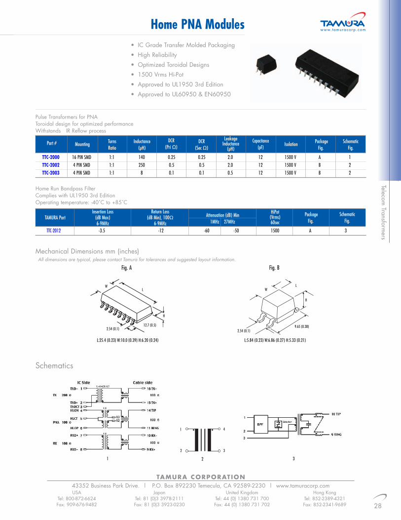
Home PNA Modules www.tamuracorp.com
Telecom Transform
ers
• IC Grade Transfer Molded Packaging• High Reliability• Optimized Toroidal Designs• 1500 Vrms Hi-Pot• Approved to UL1950 3rd Edition• Approved to UL60950 & EN60950
Mechanical Dimensions mm (inches)
Schematics
Capacitance(pF)
DCR(Pri Ω)
SchematicFig.
PackageFig.
IsolationLeakage
Inductance(µH)
DCR(Sec Ω)
Inductance(µH)
TurnsRatio
MountingPart #
TTC-2000 16 PIN SMD 1:1 140 0.25 0.25 2.0 12 1500 V A 1TTC-2002 4 PIN SMD 1:1 250 0.5 0.5 2.0 12 1500 V B 2TTC-2003 4 PIN SMD 1:1 8 0.1 0.1 0.5 12 1500 V B 2
Pulse Transformers for PNAToroidal design for optimized performanceWithstands IR Reflow process
SchematicFig.
Attenuation (dB) Min1MHz 27MHz
PackageFig.
HiPot(Vrms)60sec
Return Loss(dB Min), 100Ω
6-9MHz
Insertion Loss(dB Max)6-9MHz
TAMURA Part
TTC-2012 -3.5 -12 -60 -50 1500 A 3
Home Run Bandpass FilterComplies with UL1950 3rd EditionOperating temperature: -40˚C to +85˚C
Fig. A Fig. B
L:5.84 (0.23) W:6.86 (0.27) H:5.33 (0.21)L:25.4 (0.23) W:10.0 (0.39) H:6.20 (0.24)
1 32
32
1 4
All dimensions are typical, please contact Tamura for tolerances and suggested layout information.
2.54 (0.1)12.7 (0.5)
2.54 (0.1)9.65 (0.38)
LL
WW
H
H

Mechanical Dimensions mm (inches)
Schematics
29
TAMURA CORPORATION43352 Business Park Drive. | P.O. Box 892230 Temecula, CA 92589-2230 | www.tamuracorp.comUSA
Tel: 800-872-6624Fax: 909-676-9482
JapanTel: 81 (0)3 3978-2111Fax: 81 (0)3 3923-0230
United KingdomTel: 44 (0) 1380 731 700Fax: 44 (0) 1380 731 702
Hong KongTel: 852-2389-4321Fax: 852-2341-9689
Ultra Wideband Audio TransformersOperation Temperature of -55C˚ to130˚ for Demanding Applications
• Highest Density Package Available
• Optimized for Audio Impedance Matching Applications
• Frequency Range = 400Hz - 250kHz
• HiPot = 150Vrms (Pri:Sec)
www.tamuracorp.com
Tele
com
Tra
nsfo
rmer
s
SchematicFig.
DCR(Sec Ω)
DCR(Pri Ω)
Freq. Response
(dB)
Distortion(% MAX.)
UnBalanceCurrent(mA)
TurnsRatio
ImpedanceSecondary(Sec. Ω)
ImpedancePrimary(Pri. Ω)
Rated Power@ 1KHz(mW)
IDPart #
MX-52 40 10 K CT 10 K CT 1CT:1CT 0.25 7 +/- 2 1150 1220 1MX-58 50 600 CT 600 CT 1CT:1CT 1 7 +/- 2 78 93 1MX-59 50 500 CT 50 1CT: 0.316 1 7 +/- 2 62 5 1MX-61 50 600 CT 8 8.66CT:1 1 7 +/- 2 90 1.5 2
L:6.35 (0.25) W:6.35 (0.25) H:6.35 (0.25)
2
All dimensions are typical, please contact Tamura for tolerances and suggested layout information.
2.54 (0.1) 5.08 (0.2)
L
H
W
1
1
2
6
5
43
1
2
6
43

30
TAMURA CORPORATION43352 Business Park Drive. | P.O. Box 892230 Temecula, CA 92589-2230 | www.tamuracorp.comUSA
Tel: 800-872-6624Fax: 909-676-9482
JapanTel: 81 (0)3 3978-2111Fax: 81 (0)3 3923-0230
United KingdomTel: 44 (0) 1380 731 700Fax: 44 (0) 1380 731 702
Hong KongTel: 852-2389-4321Fax: 852-2341-9689
Ultra Wideband Audio Transformers• Highest Density Package Available
• Optimized for Audio Impedance
• Frequency Range = 100Hz - 100kHz
• HiPot = 1000Vrms (Pri:Sec)
www.tamuracorp.com
Telecom Transform
ers
1 Meets FCC Parts 68
SchematicFig.
DCR(Sec. Ω)
DCR(Pri. Ω)
Freq. Response
(dB)
Max. Pwr.Level(mW)
UnBalanceCurrent(mA)
Turns Ratio(Pri:Sec)
Impedance(Sec. Ω)
Impedance(Pri. Ω)Tamura Part #
MET-01 200k 1k 14.1CT:1CT 0.0 10.0 +/-3 5300 120 1MET-05 25k 1k 5CT:1CT 0.5 30.0 +/-3 1600 95 1MET-09 10 K CT 10 K CT 1CT:1CT 1 40.0 +/- 3 1000 1300 1MET-11 10k 2k 2.23CT:1CT 1.0 40.0 +/-3 1000 300 1MET-17 10K 500 4.47CT:1CT 1.0 40.0 +/-3 1000 80 1MET-23 1.6k 3.2 22.3CT:1 2.5 50.0 +/-3 186 0.8 3MET-24 1.5K CT 600 1.58CT:1 3 50.0 +/- 3 160 95 3MET-28 1K 50 4.47:1 3.0 50.0 +/-3 110 8 4MET-311 600 CT 600 CT 1CT:1CT 3 50.0 +/- 3 70 95 1MET-32 600 150/150 2:1:1 3 50.0 +/- 3 70 95 2MET-35 600 CT 8 8.66CT:1 4.5 50.0 +/- 3 60 1.5 3MET-39 500 50 3.16:1 3.0 50.0 +/-3 55 8 4MET-42 150 12 3.54:1 10.0 50.0 +/-3 20 2.5 4MET-461 600 600 1:1 3 50.0 +/- 3 72 93 4MET-50 10k 125 8.62:1 0.0 10.0 +/-3 1100 280 4MET-59 600 600 1:1CT 3.0 50.0 +/-3 70 95 2MET-60 135 135 CT 1:1CT 10 50.0 +/- 3 10 10 5METC-99 MU Metal Shield
SchematicsL:7.87 (0.31) W:10.4 (0.41) H:11.8 (0.465)
Mechanical Dimensions mm (inches)All dimensions are typical, please contact Tamura for tolerances and suggested layout information.
2.5 (0.098) 7.6 (0.3)
L
H
W
1
1
2
6
5
43
3
1
2
5
43
2
1 3
45
62
4
1 4
32
5
1 5
4
32
Mechanical Dimensions mm (inches)
TAMURA CORPORATION43352 Business Park Drive. | P.O. Box 892230 Temecula, CA 92589-2230 | www.tamuracorp.com
31
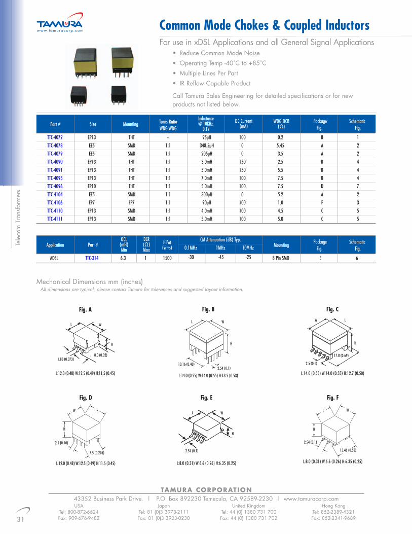
Common Mode Chokes & Coupled Inductors
USATel: 800-872-6624Fax: 909-676-9482
JapanTel: 81 (0)3 3978-2111Fax: 81 (0)3 3923-0230
United KingdomTel: 44 (0) 1380 731 700Fax: 44 (0) 1380 731 702
Hong KongTel: 852-2389-4321Fax: 852-2341-9689
For use in xDSL Applications and all General Signal Applications• Reduce Common Mode Noise• Operating Temp -40˚C to +85˚C• Multiple Lines Per Part• IR Reflow Capable Product
Call Tamura Sales Engineering for detailed specifications or for new products not listed below.
www.tamuracorp.com
Tele
com
Tra
nsfo
rmer
s
Fig. A
L:12.0 (0.48) W:12.5 (0.49) H:11.5 (0.45)
Fig. CFig. B
L:14.0 (0.55) W:14.0 (0.55) H:13.5 (0.53) L:14.0 (0.55) W:14.0 (0.55) H:12.7 (0.50)
Fig. E
L:8.0 (0.31) W:6.6 (0.26) H:6.35 (0.25)
SchematicFig.
PackageFig.
WDG DCR(Ω)
DC Current(mA)
Inductance@ 10KHz,
0.1VMountingSizePart #
TTC-4072 EP13 THT -- 95µH 100 0.2 B 1TTC-4078 EE5 SMD 1:1 348.5µH 0 5.45 A 2TTC-4079 EE5 SMD 1:1 205µH 0 3.5 A 2TTC-4090 EP13 THT 1:1 3.0mH 150 2.5 B 4TTC-4091 EP13 THT 1:1 5.0mH 150 5.5 B 4TTC-4095 EP13 THT 1:1 7.0mH 100 7.5 B 4TTC-4096 EP10 THT 1:1 5.0mH 100 7.5 D 7TTC-4104 EE5 SMD 1:1 300µH 0 5.2 A 2TTC-4106 EP7 EP7 1:1 90µH 100 1.0 F 3TTC-4110 EP13 SMD 1:1 4.0mH 100 4.5 C 5TTC-4111 EP13 SMD 1:1 5.0mH 100 5.0 C 5
Turns RatioWDG:WDG
All dimensions are typical, please contact Tamura for tolerances and suggested layout information.
SchematicFig.
PackageFig.
MountingCM Attenuation (dB) Typ.
0.1MHz 1MHz 10MHzHiPot
(Vrms)
OCL(mH)Min
Part #Application
ADSL TTC-314 6.3 1 1500 8 Pin SMD E 6
DCR(Ω)Max
-30 -45 -25
1.85 (0.073)10.16 (0.40)
8.0 (0.32)
2.54 (0.1)
L
H H
2.54 (0.1)
H
Fig. F
L:8.0 (0.31) W:6.6 (0.26) H:6.35 (0.25)
2.54 (0.1)
13.46 (0.53)
L
H
W
W
Fig. D
L:12.0 (0.48) W:12.5 (0.49) H:11.5 (0.45)
2.5 (0.10)
7.5 (0.296)
L
H
W
2.5 (0.1)
H
W L
17.8 (0.69)
L W
L W

32
TAMURA CORPORATION43352 Business Park Drive. | P.O. Box 892230 Temecula, CA 92589-2230 | www.tamuracorp.comUSA
Tel: 800-872-6624Fax: 909-676-9482
JapanTel: 81 (0)3 3978-2111Fax: 81 (0)3 3923-0230
United KingdomTel: 44 (0) 1380 731 700Fax: 44 (0) 1380 731 702
Hong KongTel: 852-2389-4321Fax: 852-2341-9689
Schematics
Common Mode Chokes & Coupled Inductors www.tamuracorp.com
Telecom Transform
ers
1 2 3 4
756

1x1 2x1 1x4
Tamura Part Number, RJ45 Connector Modules
2x4 2x816 Pin SOIC 16 Pin SMD
Tamura Part Number, Discrete Module
40 Pin SOIC# Of PortsIC Part
NumberIC
Manufacturer
3-Com 3C917ADHOC AH101
Broadcom BCM5201Crystal Semi. CS8952
Davicom DM9101Integrated Circuit ICS1890,
ICS1892Intel 82555, 82558
Level One LXT970 TTC-8100Lucent LUC3X54 Single Port TTC-8133 TTC-8103 See Page
Marconix MX98727 Applications TTC-8139 TTC-8130 for SelectionMicrolinear ML6671,6673 of 1x1
Myson MTD917,972 ConnectorsNational Semi DP83223A
DP83840DP83843
Realtek RTL8129TDK 78Q2120,2121TI TNETE2101
Winbond W89C812ADHOC AH104 TTC-8114 See Page xx
Broadcom BCM5203 TTC-8115 for Selection BCM5205 Quad Port TTC-8116 of 1x4BCM5208 Applications TTC-8117 ConnectorsBCM5209
TAMURA CORPORATION43352 Business Park Drive. | P.O. Box 892230 Temecula, CA 92589-2230 | www.tamuracorp.com
33
IC Cross Reference Guide
USATel: 800-872-6624Fax: 909-676-9482
JapanTel: 81 (0)3 3978-2111Fax: 81 (0)3 3923-0230
United KingdomTel: 44 (0) 1380 731 700Fax: 44 (0) 1380 731 702
Hong KongTel: 852-2389-4321Fax: 852-2341-9689
www.tamuracorp.com
Ethe
rnet
/LA
N T
rans
form
ers
1x1 2x1 1x4
Tamura Part Number, RJ45 Connector Modules
2x4 2x816 Pin SOIC 16 Pin SMD
Tamura Part Number, Discrete Module
40 Pin SOIC# Of PortsIC Part
NumberIC
Manufacturer
Broadcom BCM5400TTC-8135
BCM5411 Single Port TTC-8136 TIC-L041-11 See Page xx for TTC-8137 TIC-L048-11 Selection of 2x1
BCM5421 TTC-8138 TIC-L047-11 Connectors
BCM5421S 1 gigabitper system
BCM5402 Dual Port TTC-8156 See Page xx for TTC-8173 TTC-8172 Selection of 2x1 TIC-L057-14 TIC-L056-24
8 gigabits Connectors TIC-L059-14 TIC-L073-24per system
BCM5404BCM5414 BCM5424 Quad Port TTC-8156 TTC-8172 TIC-L057-14 TIC-L056-24 Consult theBCM5434 TTC-8173 TIC-L059-14 TIC-L073-24 factoryBCM5464
16 gigabits per system
BCM5464S Quad Port See Page xx forSelection of 2x1 TIC-L057-14
Connectors TIC-L059-144 gigabitsper system
TTC-8135Intel LXT1000 Single Port TTC-8136 TIC-L041-11 See Page xx for Consult the
(Level One) TTC-8137 TIC-L048-11 Selection of 2x1 factoryTTC-8138 TIC-L047-11 Connectors
10/100 Base T Ethernet
Gigabit Ethernet

TAMURA CORPORATION43352 Business Park Drive. | P.O. Box 892230 Temecula, CA 92589-2230 | www.tamuracorp.com
34
LAN 10Base-T Transformers
USATel: 800-872-6624Fax: 909-676-9482
JapanTel: 81 (0)3 3978-2111Fax: 81 (0)3 3923-0230
United KingdomTel: 44 (0) 1380 731 700Fax: 44 (0) 1380 731 702
Hong KongTel: 852-2389-4321Fax: 852-2341-9689
• Complies with IEEE 802.3 Standards
• Extended Temp versions
• Hi-Pot 1500Vrms (pri:sec)
• Designed to work with a variety of IC’s
Schematics
www.tamuracorp.com
ExtendedLL Max(µH)
SchematicFig.
PackageFig.
MountingCw(pF)
DCR(Ω)
Inductance(µH)
Turns RatioTurns Ratio
Rx TxNumber of
PortsPart #
TTC-8121 1 1:1:1 - 100 0.2 0.2 10 AUI SMT A 1TTC-8150 4 1:1 1CT:1CT 150 0.3 0.51 10 Quad Xfmr w/CMC SMT D 5TTC-8163 1 1CT:1CT 1CT:2.5CT 200 0.5 0.4 15 Xfmr w/CMC SMT C 3TTC-8123 1 1CT:1CT 1CT:1.41CT 200 0.5 0.3 20 Xfmr w/(2)CMC SMT A 4TTC-8124 1 1CT:1CT 1CT:1.41CT 200 0.5 0.3 20 Xfmr w/(2)CMC SMT A 3TTC-8142 1 1CT:1CT 1CT:2CT 140 0.4 0.3 15 Xfmr w/CMC SMT C 4TTC-8154 1 1CT:1CT 2CT:1CT 80 0.3 0.3 20 Xfmr SMT A 2
21
Fig. BFig. A
3 4 5
L:11.6 (0.46) W:6.91 (0.27) H:5.6 (0.22)
Fig. C
L:12.7 (0.50) W:6.95 (0.27) H:5.6 (0.22)L:25.4 (1.0) W:10.0 (0.76) H:6.2 (0.24)
Mechanical Dimensions mm (inches)All dimensions are typical, please contact Tamura for tolerances and suggested layout information.
1.27 (0.05)2.54 (0.1)
12.7 (0.5)1.27 (0.05)9.10 (0.360) 9.40 (0.37)
L L L
H
H
H
W W W
Fig. D
L:28.0 (1.102) W:12.2 (0.48) H:6.0 (0.236)
L
H
W
15.7(0.618)
1 Specification is a typical value
Electrical Specification @ Ta=25˚C
Ethernet/LAN
Transformers
35
TAMURA CORPORATION43352 Business Park Drive. | P.O. Box 892230 Temecula, CA 92589-2230 | www.tamuracorp.comUSA
Tel: 800-872-6624Fax: 909-676-9482
JapanTel: 81 (0)3 3978-2111Fax: 81 (0)3 3923-0230
United KingdomTel: 44 (0) 1380 731 700Fax: 44 (0) 1380 731 702
Hong KongTel: 852-2389-4321Fax: 852-2341-9689
Schematics
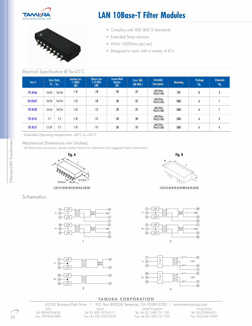
LAN 10Base-T Filter Modules• Complies with IEEE 802.3 Standards
• Extended Temp versions
• Hi-Pot 1500Vrms (pri:sec)
• Designed to work with a variety of IC’s
www.tamuracorp.com
1
3
2
4
Mechanical Dimensions mm (inches)All dimensions are typical, please contact Tamura for tolerances and suggested layout information.
SchematicFig.
PackageFig.Mounting
Cross Talk(dB MIN.)
Common ModeRejection
(dB)
Insertion Loss1-10MHz
(dB)
Turns RatioPri SecPart #
TTC-8166 1ct:1ct 1ct:1ct -1.0 -18 -30 -35 THT B 2
TTC-81641 1ct:1ct 1ct:1ct -1.0 -18 -30 -35 SMD A 1
TTC-8128 1ct:1ct 1ct:1ct -1.0 -15 -30 -35 SMD A 1
TTC-8145 1:1 1:1 -1.0 -15 -30 -30 SMD A 3
TTC-8157 1:1.41 1:1 -1.0 -15 -30 -35 SMD A 4
ExtendedDescription
Return Loss5-10 MHz
(dB)
LAN-Xfmr-Fltr(2)-CMC
LAN-Xfmr-Fltr(2)-CMC
LAN-Xfmr-Fltr(2)-CMC
LAN-Xfmr-Fltr(2)-CMC
LAN-Xfmr-Fltr(2)-CMC
Fig. B
L:25.4 (1.0) W:10.16 (0.40) H:6.35 (0.25)
L
H
W
Fig. A
L:25.4 (1.0) W:10.0 (0.76) H:6.2 (0.24)
2.54 (0.1)12.7 (0.5)
L
H
W
1 Extended Operating temperature: -40˚C to +85˚C
Electrical Specification @ Ta=25˚C
Ethe
rnet
/LA
N T
rans
form
ers

TAMURA CORPORATION43352 Business Park Drive. | P.O. Box 892230 Temecula, CA 92589-2230 | www.tamuracorp.com
36
10/100 Base-T Transformers
USATel: 800-872-6624Fax: 909-676-9482
JapanTel: 81 (0)3 3978-2111Fax: 81 (0)3 3923-0230
United KingdomTel: 44 (0) 1380 731 700Fax: 44 (0) 1380 731 702
Hong KongTel: 852-2389-4321Fax: 852-2341-9689
Surface Mount Single Port Transformer Modules• Complies with IEEE 802.3 Standards
• Inductance of 350µH Min. at 8mA Bias
• Extended Temperature Versions
• Hi-Pot 1500Vrms (Pri:Sec)
• Designed to work with a variety of IC’s
www.tamuracorp.com
Fig. BFig. A
Return Loss(@ 80 MHz)(dB MAX.)
SchematicFig.
PackageFig.
MountingCross Talk
(0.1 -100 MHz)(dB MIN.)
Common Mode Rejection(0.1 -100 MHz)
(dB MIN.)Insertion Loss(0.1-100 MHz)
(dB MAX.)Turns Ratio
Rx TxPart #
TTC-8100 1ct:1ct 1ct:1ct -1.0 -12 -35 -35 16 Pin SOIC A 1
TTC-8103 1ct:1ct 1ct:1ct -1.0 -12 -35 -35 16 Pin SMD B 3
TTC-8106 2ct:1ct 1ct:1ct -1.1 -12 -35 -35 16 Pin SMD B 5
TTC-8130 1ct:1ct 1ct:1ct -1.0 -12 -35 -35 16 Pin SMD B 4
TTC-8139 1ct:1ct 1ct:1ct -1.0 -12 -40 -40 16 Pin SOIC C 6
TTC-8143 1ct:1ct 1ct:1ct -1.1 -11 -30 -35 14 Pin D 7PCMCIA
TTC-8144 1ct:1ct 1ct:1ct -1.1 -11 -30 -35 16 Pin E 8PCMCIA
TTC-8146 2ct:1ct 1ct:1ct -1.1 -12 -35 -35 16 Pin SMD B 9
TTC-81471 1ct:1ct 1ct:1ct -1.1 -12 -40 -40 16 Pin SOIC G 2
TTC-81521 1ct:1ct 1ct:1ct -1.1 -12 -35 -35 16 Pin SOIC G 10
TTC-8161 1ct:1 1ct:1ct -1.0 -12 -35 -35 16 Pin SMD B 11
TTC-81681 1ct:1ct 1ct:1 -1.0 -12 -35 -35 16 Pin SMD B 3
TTC-8171 1ct:1ct 1ct:1ct -1.0 -12 -30 -35 16 Pin PCMCIA F 12
Fig. C
L:11.6 (0.46) W:6.91 (0.27) H:5.6 (0.22)
Fig. D
L:20.3 (0.80) W:13.3 (0.524) H:2.39 (0.094)
Fig. E
L:14.22 (0.56) W:14.22 (0.56) H:2.30 (0.090)
L:12.7 (0.50) W:6.95 (0.27) H:5.6 (0.22)L:25.4 (1.0) W:10.0 (0.76) H:6.2 (0.24)
Mechanical DimensionsAll dimensions are typical, please contact Tamura for tolerances and suggested layout information.
1 Extended Operating Temperature: -40˚C to + 85˚C
1.27 (0.05)12.7 (0.50)
1.27 (0.05) 2.54 (0.1) 17.2 (0.677)
1.27 (0.05) 17.0 (0.67)
2.54 (0.1)
9.10 (0.36) 9.4 (0.37)
L L L L
L
H
H
HH
H
W W W W
W
Fig. F
L:11.60 (0.457) W:12.6 (0.496) H:2.2 (0.087)
1.27 (0.05)
L
H
15.60(0.614)
W
Fig. G
L:12.7 (0.50) W:6.95 (0.274) H:4.83 (0.19)
1.27 (0.05)
L
H
9.4 (0.37)
W
Electrical Specification @ Ta=25˚C
Ethernet/LAN
Transformers

37
TAMURA CORPORATION43352 Business Park Drive. | P.O. Box 892230 Temecula, CA 92589-2230 | www.tamuracorp.comUSA
Tel: 800-872-6624Fax: 909-676-9482
JapanTel: 81 (0)3 3978-2111Fax: 81 (0)3 3923-0230
United KingdomTel: 44 (0) 1380 731 700Fax: 44 (0) 1380 731 702
Hong KongTel: 852-2389-4321Fax: 852-2341-9689
10/100 Base-T Transformerswww.tamuracorp.com
Schematics
5
43
21
6
7 8
Ethe
rnet
/LA
N T
rans
form
ers

38
TAMURA CORPORATION43352 Business Park Drive. | P.O. Box 892230 Temecula, CA 92589-2230 | www.tamuracorp.comUSA
Tel: 800-872-6624Fax: 909-676-9482
JapanTel: 81 (0)3 3978-2111Fax: 81 (0)3 3923-0230
United KingdomTel: 44 (0) 1380 731 700Fax: 44 (0) 1380 731 702
Hong KongTel: 852-2389-4321Fax: 852-2341-9689
10/100 Base-T Transformers www.tamuracorp.com
1211
109
Ethernet/LAN
Transformers

TAMURA CORPORATION43352 Business Park Drive. | P.O. Box 892230 Temecula, CA 92589-2230 | www.tamuracorp.com
39
10/100 Base-T Transformers
USATel: 800-872-6624Fax: 909-676-9482
JapanTel: 81 (0)3 3978-2111Fax: 81 (0)3 3923-0230
United KingdomTel: 44 (0) 1380 731 700Fax: 44 (0) 1380 731 702
Hong KongTel: 852-2389-4321Fax: 852-2341-9689
Surface Mount Dual/Quad Port Transformer Modules• Complies with IEEE 802.3 Standards
• Inductance of 350µH Min. at 8mA Bias
• Hi-Pot 1500Vrms (Pri:Sec)
• Designed to work with a variety of IC’s
www.tamuracorp.com
Ethe
rnet
/LA
N T
rans
form
ers
Fig. A
L:28.0 (1.102) W:12.2 (0.48) H:6.0 (0.236)
Mechanical Dimensions mm (inches)All dimensions are typical, please contact Tamura for tolerances and suggested layout information.
1.27 (0.05)
15.7 (0.618)
L
H
W
Return Loss(@ 80 MHz)(dB MAX.)
SchematicFig.
PackageFig.
MountingCross Talk
(0.1 -100 MHz)(dB MIN.)
Common Mode Rejection(0.1 -100 MHz)
(dB MIN.)Insertion Loss(0.1-100 MHz)
(dB MAX.)Turns Ratio
Tx RxPart #
TTC-81691 1CT:1CT 1CT:1CT -1 -12 -30 -30 SMT A 1
TTC-8153 1CT:1CT 1:1 -1 -12 -35 -30 SMT A 2
TTC-8158 1CT:1CT 1:1 -1 -12 -35 -30 SMT A 3
1 Dual Port Module
Electrical Specification @ Ta=25˚C

40
TAMURA CORPORATION43352 Business Park Drive. | P.O. Box 892230 Temecula, CA 92589-2230 | www.tamuracorp.comUSA
Tel: 800-872-6624Fax: 909-676-9482
JapanTel: 81 (0)3 3978-2111Fax: 81 (0)3 3923-0230
United KingdomTel: 44 (0) 1380 731 700Fax: 44 (0) 1380 731 702
Hong KongTel: 852-2389-4321Fax: 852-2341-9689
10/100 Base-T Transformers www.tamuracorp.com
Ethernet/LAN
Transformers
Schematics
1
3
2

TAMURA CORPORATION43352 Business Park Drive. | P.O. Box 892230 Temecula, CA 92589-2230 | www.tamuracorp.com
41
10/100/1000 Base-T Transformers
USATel: 800-872-6624Fax: 909-676-9482
JapanTel: 81 (0)3 3978-2111Fax: 81 (0)3 3923-0230
United KingdomTel: 44 (0) 1380 731 700Fax: 44 (0) 1380 731 702
Hong KongTel: 852-2389-4321Fax: 852-2341-9689
Surface Mount Single Port Transformer Modules• Complies with IEEE 802.3 Standards
• Inductance of 350µH min at 8mA Bias
• Hi-Pot 1500Vrms (Pri:Sec)
• Designed to work with a variety IC’s
• Enhanced Common Mode attenuation
www.tamuracorp.com
Ethe
rnet
/LA
N T
rans
form
ers
Schematics
Fig. BFig. A
ExtendedDescription
Return Loss(@ 80 MHz)(dB MAX.)
SchematicFig.
PackageFig.Mounting
Cross Talk (0.1 - 100MHz)
(dB MIN.)
Common Mode Rejection(0.1 - 100 MHz)
(dB MIN.)
InsertionLoss
(0.1-100 MHz)(dB MAX.)
Turns Ratio
Rx TxPart #
TTC-8135 1ct:1ct 1ct:1ct -1.00 -10 -30 -354 Channel
24 Pin SOIC A 1Tx/Rx
TTC-8136 1ct:1ct 1ct:1ct -1.00 -10 -30 -354 Channel Tx/Rx
24 Pin SOIC A 2x/AutoXfmr
TTC-8137 1ct:1ct 1ct:1ct -1.00 -10 -30 -354 Channel Tx/Rx
24 Pin 1mm B 2x/AutoXfmr
TTC-8138 1ct:1ct 1ct:1ct -1.00 -10 -30 -354 Channel
24 Pin 1mm B 1Tx/Rx
L:17.53 (0.69) W:12.2 (0.48) H:6.1 (0.24) L:13.6 (0.54) W:15.1 (0.59) H:6.30 (0.248)
21
Mechanical DimensionsAll dimensions are typical, please contact Tamura for tolerances and suggested layout information.
1.0 (0.04) 18.8 (0.74)1.27 (0.05) 15.24 (0.6)
L L
H
H
WW
Electrical Specification @ Ta=25˚C

42
TAMURA CORPORATION43352 Business Park Drive. | P.O. Box 892230 Temecula, CA 92589-2230 | www.tamuracorp.comUSA
Tel: 800-872-6624Fax: 909-676-9482
JapanTel: 81 (0)3 3978-2111Fax: 81 (0)3 3923-0230
United KingdomTel: 44 (0) 1380 731 700Fax: 44 (0) 1380 731 702
Hong KongTel: 852-2389-4321Fax: 852-2341-9689
10/100/1000 Base-T TransformersSurface Mount Dual Port Transformer Modules
• Complies with IEEE 802.3 Standards• Inductance of 350µH min at 8mA Bias• Hi-Pot 1500Vrms (Pri:Sec)• Auto MDI/MDIX Compatible• Enhanced Common Mode attenuation• Designed to work with a variety IC’s
www.tamuracorp.com
Return Loss(dB MAX.)
1-30MHz 80MHz
SchematicFig.
PackageFig.
Cross Talk (0.1 - 100 MHz)(dB MIN.)
Common Mode Rejection(0.1 - 100 MHz)
(dB MIN.)
Insertion Loss(0.1-100 MHz)
(dB MAX.)
Turns Ratio
Tx Rx
Part #
TTC-8156 1CT:1CT 1CT:1CT -1 -18 -12 -30 -30 A 1
TTC-8172 1CT:1CT 1CT:1CT -1 -18 -12 -30 -30 B 2
TTC-8173 1CT:1CT 1CT:1CT -1 -18 -12 -30 -30 A 3
Ethernet/LAN
TransformersSchematics
Fig. BFig. A
L:28.0 (1.102) W:12.2 (0.48) H:7.5 (0.295) L:27.67 (1.09) W:7.37 (0.29) H:8.64 (0.34)
31 2
Mechanical DimensionsAll dimensions are typical, please contact Tamura for tolerances and suggested layout information.
1.02 (0.04)
15.7 (0.62)
L
H
W
1.0 (0.04)
10.67 (0.42)
L
H
W
Electrical Specification @ Ta=25˚C

TAMURA CORPORATION43352 Business Park Drive. | P.O. Box 892230 Temecula, CA 92589-2230 | www.tamuracorp.com
43
Power Over Ethernet Transformers
USATel: 800-872-6624Fax: 909-676-9482
JapanTel: 81 (0)3 3978-2111Fax: 81 (0)3 3923-0230
United KingdomTel: 44 (0) 1380 731 700Fax: 44 (0) 1380 731 702
Hong KongTel: 852-2389-4321Fax: 852-2341-9689
Designed for IP Phone and Auto MDIX Applications• Complies with IEEE 802.3af and ANSI x3.263
• Inductance of 350µH min. at 8mA Bias
• HiPot 1500Vrms (pri:sec)
• Meets Profile requirements for IR Reflow
Schematics
www.tamuracorp.com
Ethe
rnet
/LA
N T
rans
form
ers
Cross Talk(dB Min)
1 - 100MHz
SchematicFig.
PackageFig.
Differential Mode Rejection(dB Min)
30 - 100MHz
Return Loss(dB Min)
1-30MHz 80MHz
Insertion Loss(dB Max)
0.1 - 100MHz
Turns Ratio
Tx RxPart #
TTC-8170 1CT:1CT 1CT:1CT -1 -16 -12 -33 -30 A 1
Mechanical DimensionsAll dimensions are typical, please contact Tamura for tolerances and suggested layout information.
11.68(0.460)
5.46(0.215)
14.80(0.583)
Electrical Specification @ Ta=25˚C
Fig. A
1

RJ45 Connectors
44
TAMURA CORPORATION43352 Business Park Drive. | P.O. Box 892230 Temecula, CA 92589-2230 | www.tamuracorp.comUSA
Tel: 800-872-6624Fax: 909-676-9482
JapanTel: 81 (0)3 3978-2111Fax: 81 (0)3 3923-0230
United KingdomTel: 44 (0) 1380 731 700Fax: 44 (0) 1380 731 702
Hong KongTel: 852-2389-4321Fax: 852-2341-9689
RJ45 Integrated Connector1X1 Common Mode Choke Module
• Complies with IEEE 802.3 Standards
• Operating Temp -20˚C to +85˚C
• HiPot 1500Vrms (pri:sec)
• Designed to reduce Radiated and Conducted EMI
www.tamuracorp.com
OCL (µH Min)0.1V @ 10kHz
DCR (Ω Max)
Each Winding 1MHz 5MHz 20MHz
Common Mode Atenuation (dB Typ)
70MHz 200MHz 500MHz
65 0.5 8 17 23 25 22 11
Mechanical DimensionsPlease contact Tamura for tolerances and suggested layout information.
L
H
W
Part # Turns Ratio (IC:LINE)
Tx Rx
Configuration1Latch/Tab LED Options Schematic Diagram Package Style
Package Dimensionsmm(inches) Typ
L W H
TIC-L066-11 NA NA C C DOWN NO 1 A
TIC-L068-11 NA NA C C DOWN YES 2 B
Tx Rx21.6 15.8 13.45
(0.850) (0.625) (0.530)21.6 15.8 13.45
(0.850) (0.625) (0.530)
Product Selector
1 C-Choke; T-Transformer; A-Auto Transformer
Package & Weight Information
60 420 1680 6.3QTY/Tray QTY/Box QTY/Cartoon Weight/each(g)
All Electrical Data Specified at Ta=-20˚ to +85˚C for all parts in this Series
Fig. A
L
H
W
Fig. B
Schematics
1 2
1 1
1
12
11
INPUT
LEFT
RIGHT
OUTPUT
2
4
5
1
2
4
5
14
13
2 2
3 3
6 6
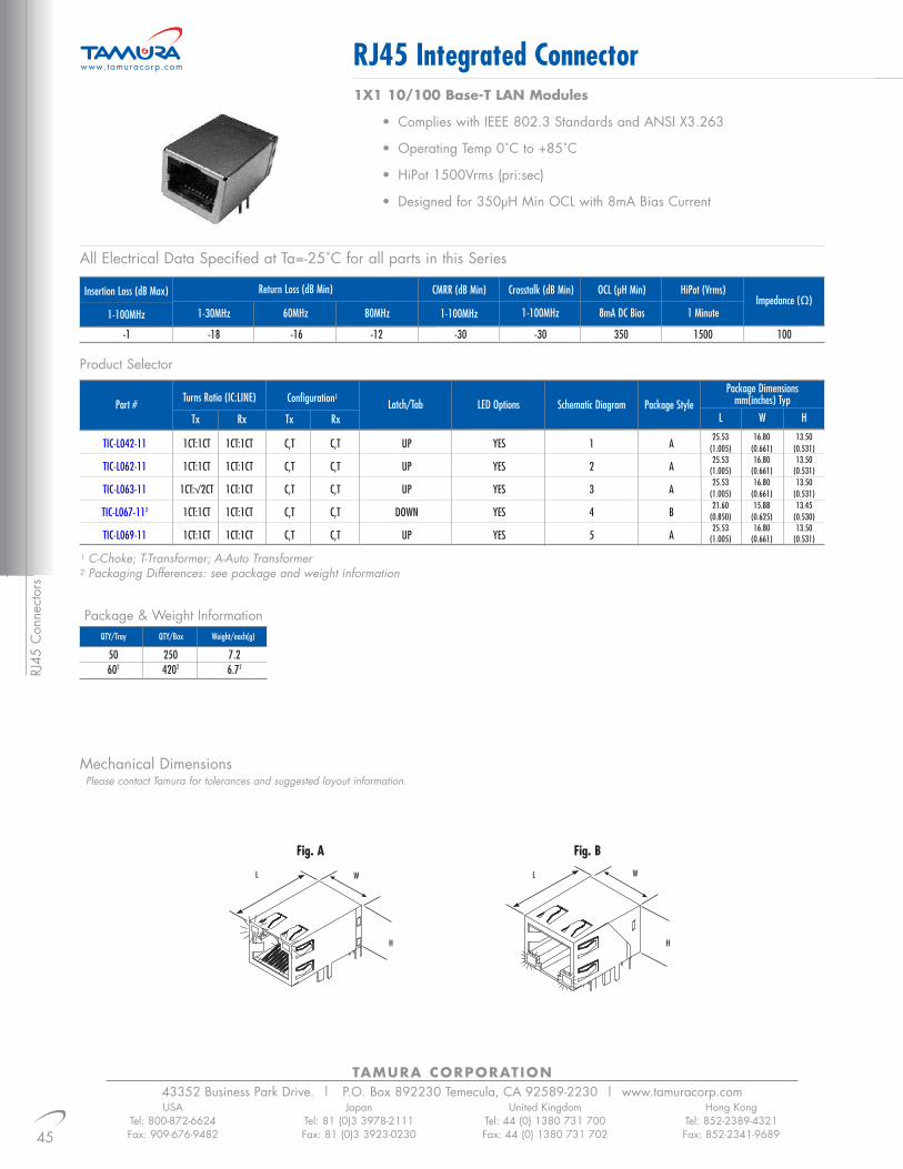
RJ45
Con
nect
ors
TAMURA CORPORATION43352 Business Park Drive. | P.O. Box 892230 Temecula, CA 92589-2230 | www.tamuracorp.com
45
RJ45 Integrated Connector
USATel: 800-872-6624Fax: 909-676-9482
JapanTel: 81 (0)3 3978-2111Fax: 81 (0)3 3923-0230
United KingdomTel: 44 (0) 1380 731 700Fax: 44 (0) 1380 731 702
Hong KongTel: 852-2389-4321Fax: 852-2341-9689
www.tamuracorp.com
1X1 10/100 Base-T LAN Modules
• Complies with IEEE 802.3 Standards and ANSI X3.263
• Operating Temp 0˚C to +85˚C
• HiPot 1500Vrms (pri:sec)
• Designed for 350µH Min OCL with 8mA Bias Current
Insertion Loss (dB Max)
1-100MHz 1-30MHz
Return Loss (dB Min)
60MHz 80MHz 1-100MHz
CMRR (dB Min) Crosstalk (dB Min) OCL (µH Min) HiPot (Vrms)
1-100MHz 8mA DC Bias 1 MinuteImpedance (Ω)
-1 -18 -16 -12 -30 -30 350 1500 100
Part #Turns Ratio (IC:LINE)
Tx Rx
Configuration1Latch/Tab LED Options Schematic Diagram Package Style
Package Dimensionsmm(inches) Typ
L W H
TIC-L042-11 1CT:1CT 1CT:1CT C,T C,T UP YES 1 A
TIC-L062-11 1CT:1CT 1CT:1CT C,T C,T UP YES 2 A
TIC-L063-11 1CT:√2CT 1CT:1CT C,T C,T UP YES 3 A
TIC-L067-112 1CT:1CT 1CT:1CT C,T C,T DOWN YES 4 B
TIC-L069-11 1CT:1CT 1CT:1CT C,T C,T UP YES 5 A
Tx Rx25.53 16.80 13.50
(1.005) (0.661) (0.531)25.53 16.80 13.50
(1.005) (0.661) (0.531)25.53 16.80 13.50
(1.005) (0.661) (0.531)21.60 15.88 13.45
(0.850) (0.625) (0.530)25.53 16.80 13.50
(1.005) (0.661) (0.531)
Product Selector
1 C-Choke; T-Transformer; A-Auto Transformer2 Packaging Differences: see package and weight information
Package & Weight Information
50 250 7.2602 4202 6.72
QTY/Tray QTY/Box Weight/each(g)
Mechanical DimensionsPlease contact Tamura for tolerances and suggested layout information.
All Electrical Data Specified at Ta=-25˚C for all parts in this Series
L
H
W
Fig. A
L
H
W
Fig. B

46
TAMURA CORPORATION43352 Business Park Drive. | P.O. Box 892230 Temecula, CA 92589-2230 | www.tamuracorp.comUSA
Tel: 800-872-6624Fax: 909-676-9482
JapanTel: 81 (0)3 3978-2111Fax: 81 (0)3 3923-0230
United KingdomTel: 44 (0) 1380 731 700Fax: 44 (0) 1380 731 702
Hong KongTel: 852-2389-4321Fax: 852-2341-9689
Schematics
RJ45 Integrated Connector www.tamuracorp.com
RJ45 Connectors
1 2
3
5
4

TAMURA CORPORATION43352 Business Park Drive. | P.O. Box 892230 Temecula, CA 92589-2230 | www.tamuracorp.com
47
RJ45 Integrated Connector
USATel: 800-872-6624Fax: 909-676-9482
JapanTel: 81 (0)3 3978-2111Fax: 81 (0)3 3923-0230
United KingdomTel: 44 (0) 1380 731 700Fax: 44 (0) 1380 731 702
Hong KongTel: 852-2389-4321Fax: 852-2341-9689
www.tamuracorp.com
RJ45
Con
nect
ors
1X1 10/100 Base-T LAN Modules with LED’s
• Enhanced Crosstalk Performance
• Complies with IEEE 802.3 Standards and ANSI X3.263
• Operating Temp 0˚C to +85˚C
• HiPot 1500Vrms (pri:sec)
• Designed for 350µH Min OCL with 8mA Bias Current
Insertion Loss (dB Max)
1-100MHz 1-30MHz
Return Loss (dB Min)
60MHz 80MHz 1-100MHz
CMRR (dB Min) Crosstalk (dB Min) OCL (µH Min) HiPot (Vrms)
1-100MHz 8mA DC Bias 1 MinuteImpedance (Ω)
-1 -18 -16 -12 -30 -35 350 1500 100
Part # Turns Ratio (IC:LINE)
Tx Rx
Configuration1 Latch/Tab LED Options Schematic Diagram Package StylePackage Dimensions
mm(inches) TypL W H
TIC-L033-11 1CT:1 1CT:1CT A,C,T T,C UP YES 1 D
TIC-L034-11 1CT:1 1CT:1CT A,C,T T,C UP YES 1 E
TIC-L035-11 1CT:1 1CT:1CT A,C,T T,C UP YES 1 A
TIC-L036-11 1CT:1 1CT:1CT A,C,T T,C UP YES 2 C
TIC-L037-11 1CT:1 1CT:1CT A,C,T T,C UP YES 3 C
TIC-L038-11 1CT:1 1CT:1CT A,C,T T,C UP YES 4 B
TIC-L039-11 1CT:1 1CT:1CT A,C,T T,C UP YES 5 B
TIC-L040-11 1CT:1 1CT:1CT A,C,T T,C UP YES 4 C
TIC-L058-112 1CT:1 1CT:1CT A,C,T T,C DOWN YES 6 F
TIC-L075-112 1CT:1CT 1CT:1CT C,T C,T DOWN YES 7 G
Tx Rx25.53 16.80 13.50
(1.005) (0.661) (0.531)25.53 16.80 13.50
(1.005) (0.661) (0.531)25.53 16.80 13.50
(1.005) (0.661) (0.531)21.6 15.8 13.45
(0.850) (0.625) (0.530)25.53 16.80 13.50
(1.005) (0.661) (0.531)25.53 16.80 13.50
(1.005) (0.661) (0.531)25.53 16.80 13.50
(1.005) (0.661) (0.531)25.53 16.80 13.50
(1.005) (0.661) (0.531)21.6 15.8 13.45
(0.850) (0.625) (0.530)21.69 15.85 13.45
(0.854) (0.624) (0.530)
Product Selector
1 C-Choke; T-Transformer; A-Auto Transformer2 Packaging Differences: see package and weight information
Package & Weight Information
50 1000 7.21002 10002 6.32
QTY/Tray QTY/Box Weight/each(g)
Mechanical DimensionsPlease contact Tamura for tolerances and suggested layout information.
All Electrical Data Specified at Ta=-25˚ for all parts in this Series
L
H
W
Fig. A
L
H
W
Fig. B
L
H
W
Fig. C
L
H
W
Fig. D

48
TAMURA CORPORATION43352 Business Park Drive. | P.O. Box 892230 Temecula, CA 92589-2230 | www.tamuracorp.comUSA
Tel: 800-872-6624Fax: 909-676-9482
JapanTel: 81 (0)3 3978-2111Fax: 81 (0)3 3923-0230
United KingdomTel: 44 (0) 1380 731 700Fax: 44 (0) 1380 731 702
Hong KongTel: 852-2389-4321Fax: 852-2341-9689
RJ45 Integrated Connector www.tamuracorp.com
RJ45 Connectors
Schematics
L
H
W
Fig. E
L
H
W
Fig. F
L
H
W
Fig. G
1 2

TAMURA CORPORATION43352 Business Park Drive. | P.O. Box 892230 Temecula, CA 92589-2230 | www.tamuracorp.com
49
RJ45 Integrated Connector
USATel: 800-872-6624Fax: 909-676-9482
JapanTel: 81 (0)3 3978-2111Fax: 81 (0)3 3923-0230
United KingdomTel: 44 (0) 1380 731 700Fax: 44 (0) 1380 731 702
Hong KongTel: 852-2389-4321Fax: 852-2341-9689
www.tamuracorp.com
RJ45
Con
nect
ors
3 4
5

50
TAMURA CORPORATION43352 Business Park Drive. | P.O. Box 892230 Temecula, CA 92589-2230 | www.tamuracorp.comUSA
Tel: 800-872-6624Fax: 909-676-9482
JapanTel: 81 (0)3 3978-2111Fax: 81 (0)3 3923-0230
United KingdomTel: 44 (0) 1380 731 700Fax: 44 (0) 1380 731 702
Hong KongTel: 852-2389-4321Fax: 852-2341-9689
RJ45 Integrated Connector www.tamuracorp.com
RJ45 Connectors
6 7

TAMURA CORPORATION43352 Business Park Drive. | P.O. Box 892230 Temecula, CA 92589-2230 | www.tamuracorp.com
51
RJ45 Integrated Connector
USATel: 800-872-6624Fax: 909-676-9482
JapanTel: 81 (0)3 3978-2111Fax: 81 (0)3 3923-0230
United KingdomTel: 44 (0) 1380 731 700Fax: 44 (0) 1380 731 702
Hong KongTel: 852-2389-4321Fax: 852-2341-9689
www.tamuracorp.com
RJ45
Con
nect
ors
1X1 10/100 Base-T LAN Modules• Enhanced Crosstalk Performance• Enhanced Common Mode Rejection Performance• Complies with IEEE 802.3 Standards and ANSI X3.263• Operating Temp 0˚C to +85˚C• HiPot 1500Vrms (pri:sec)• Designed for 350µH Min OCL with 8mA Bias Current
Insertion Loss (dB Max)
1-100MHz 1-30MHz
Return Loss (dB Min)
60MHz 80MHz 1-100MHz
CMRR (dB Min) Crosstalk (dB Min) OCL (µH Min) HiPot (Vrms)
1-100MHz 8mA DC Bias 1 MinuteImpedance (Ω)
-1 -18 -16 -12 -35 -35 350 1500 100
Part # Turns Ratio (IC:LINE)
Tx Rx
Configuration1 Latch/Tab LED Options Schematic Diagram Package StylePackage Dimensions
mm(inches) TypL W H
TIC-L001-11 1CT:1CT 1CT:1CT C,T C,T DOWN NO 7 C
TIC-L002-11 1CT:1CT 1CT:1CT C,T C,T DOWN NO 5 A
TIC-L003-11 1CT:1 1CT:1CT A,C,T T,C DOWN NO 1 A
TIC-L004-11 1CT:1 1CT:1CT A,C,T T,C DOWN NO 6 A
TIC-L006-11 1CT:1CT 1CT:1CT C,T C,T DOWN NO 2 A
TIC-L007-11 1CT:1 1CT:1CT A,C,T T,C DOWN NO 1 A
TIC-L008-11 1CT:1 1CT:1CT A,C,T T,C DOWN NO 3 A
TIC-L009-11 1CT:1CT 1CT:1CT C,T C,T DOWN NO 2 B
TIC-L010-11 1CT:1 1CT:1CT A,C,T T,C DOWN NO 4 B
TIC-L011-11 1CT:1 1CT:1CT A,C,T T,C DOWN NO 1 C
TIC-L012-11 1CT:1 1CT:1CT A,C,T T,C DOWN NO 4 C
TIC-L013-11 1CT:1 1CT:1CT A,C,T T,C DOWN NO 1 D
TIC-L014-11 1CT:1 1CT:1CT A,C,T T,C DOWN NO 4 D
TIC-L015-11 1CT:2.5CT 1CT:1CT C,T C,T DOWN NO 8 A
Tx Rx21.6 15.8 13.45
(0.850) (0.625) (0.530)21.6 15.8 13.45
(0.850) (0.625) (0.530)21.6 15.8 13.45
(0.850) (0.625) (0.530)21.6 15.8 13.45
(0.850) (0.625) (0.530)21.6 15.8 13.45
(0.850) (0.625) (0.530)21.6 15.8 13.45
(0.850) (0.625) (0.530)21.6 15.8 13.45
(0.850) (0.625) (0.530)21.6 15.8 13.45
(0.850) (0.625) (0.530)21.6 15.8 13.45
(0.850) (0.625) (0.530)21.6 15.8 13.45
(0.850) (0.625) (0.530)21.6 15.8 13.45
(0.850) (0.625) (0.530)21.6 15.8 13.45
(0.850) (0.625) (0.530)21.6 15.8 13.45
(0.850) (0.625) (0.530)21.6 15.8 13.45
(0.850) (0.625) (0.530)
Product Selector
1 C-Choke; T-Transformer; A-Auto Transformer2 Packaging Differences: see package and weight information
Package & Weight Information
100 1000 6.3
QTY/Tray QTY/Box Weight/each(g)
All Electrical Data Specified at Ta=-25˚ for all parts in this Series

52
TAMURA CORPORATION43352 Business Park Drive. | P.O. Box 892230 Temecula, CA 92589-2230 | www.tamuracorp.comUSA
Tel: 800-872-6624Fax: 909-676-9482
JapanTel: 81 (0)3 3978-2111Fax: 81 (0)3 3923-0230
United KingdomTel: 44 (0) 1380 731 700Fax: 44 (0) 1380 731 702
Hong KongTel: 852-2389-4321Fax: 852-2341-9689
Schematics
RJ45 Integrated Connector www.tamuracorp.com
RJ45 Connectors
Mechanical DimensionsPlease contact Tamura for tolerances and suggested layout information.
L
H
W
Fig. A
L
H
W
Fig. B
L
H
W
Fig. C
L
H
W
Fig. D
21
INPUT OUTPUTOUTPUTINPUT
SHIELD SHIELD

TAMURA CORPORATION43352 Business Park Drive. | P.O. Box 892230 Temecula, CA 92589-2230 | www.tamuracorp.com
53
RJ45 Integrated Connector
USATel: 800-872-6624Fax: 909-676-9482
JapanTel: 81 (0)3 3978-2111Fax: 81 (0)3 3923-0230
United KingdomTel: 44 (0) 1380 731 700Fax: 44 (0) 1380 731 702
Hong KongTel: 852-2389-4321Fax: 852-2341-9689
www.tamuracorp.com
RJ45
Con
nect
ors
3 4
5 6
INPUT OUTPUT
SHIELD
INPUT OUTPUT
INPUT OUTPUT
INPUT OUTPUT
SHIELD

54
TAMURA CORPORATION43352 Business Park Drive. | P.O. Box 892230 Temecula, CA 92589-2230 | www.tamuracorp.comUSA
Tel: 800-872-6624Fax: 909-676-9482
JapanTel: 81 (0)3 3978-2111Fax: 81 (0)3 3923-0230
United KingdomTel: 44 (0) 1380 731 700Fax: 44 (0) 1380 731 702
Hong KongTel: 852-2389-4321Fax: 852-2341-9689
RJ45 Integrated Connector www.tamuracorp.com
RJ45 Connectors
7 8
INPUT OUTPUT
INPUT OUTPUT

TAMURA CORPORATION43352 Business Park Drive. | P.O. Box 892230 Temecula, CA 92589-2230 | www.tamuracorp.com
55
RJ45 Integrated Connector
USATel: 800-872-6624Fax: 909-676-9482
JapanTel: 81 (0)3 3978-2111Fax: 81 (0)3 3923-0230
United KingdomTel: 44 (0) 1380 731 700Fax: 44 (0) 1380 731 702
Hong KongTel: 852-2389-4321Fax: 852-2341-9689
www.tamuracorp.com
RJ45
Con
nect
ors
1X4 10/100 Base-T LAN Modules
• Enhanced Crosstalk Performance
• Enhanced Common Mode Rejection Performance
• Complies with IEEE 802.3 Standards and ANSI X3.263
• Operating Temp 0˚C to +85˚C
• HiPot 1500Vrms (pri:sec)
• Designed for 350µH Min OCL with 8mA Bias Current
Insertion Loss (dB Max)
1-100MHz 1-30MHz
Return Loss (dB Min)
60MHz 80MHz 1-100MHz
CMRR (dB Min) Crosstalk (dB Min) OCL (µH Min) HiPot (Vrms)
1-100MHz 8mA DC Bias 1 MinuteImpedance (Ω)
-1 -18 -16 -12 -35 -35 350 1500 100
Part # Turns Ratio (IC:LINE)
Tx Rx
Configuration1 Latch/Tab LED Options Schematic Diagram Package StylePackage Dimensions
mm(inches) TypL W H
TIC-L005-14 1CT:1CT 1CT:1CT C,T C,T DOWN NO 1 A
TIC-L016-14 1CT:1 1CT:1CT A,C,T T,C DOWN NO 2 A
TIC-L017-14 1CT:1CT 1CT:1CT C,T C,T DOWN NO 3 A
TIC-L018-14 1:1 1CT:1CT T,C C,T DOWN NO 4 A
TIC-L044-142,3 1CT:1 1CT:1CT A,C,T T,C DOWN YES 5 B
TIC-L050-142,3 1CT:1CT 1CT:1CT C,T C,T DOWN YES 6 B
Tx Rx21.6 57.88 13.45
(0.850) (2.279) (0.530)21.6 57.88 13.45
(0.850) (2.279) (0.530)21.6 57.88 13.45
(0.850) (2.279) (0.530)21.6 57.88 13.45
(0.850) (2.279) (0.530)21.6 57.88 13.45
(0.850) (2.279) (0.530)21.6 57.88 13.45
(0.850) (2.279) (0.530)
Product Selector
1 C-Choke; T-Transformer; A-Auto Transformer2 Minimum CMRR of -30dB from 1-100MHz3 Weight information per below
Package & Weight Information
25 100 18.3 (23.43)
QTY/Tray QTY/Box Weight/each(g)
Mechanical DimensionsPlease contact Tamura for tolerances and suggested layout information.
All Electrical Data Specified at Ta=-25˚ for all parts in this Series
L
H
W
Fig. A
W
H
L
Fig. B

56
TAMURA CORPORATION43352 Business Park Drive. | P.O. Box 892230 Temecula, CA 92589-2230 | www.tamuracorp.comUSA
Tel: 800-872-6624Fax: 909-676-9482
JapanTel: 81 (0)3 3978-2111Fax: 81 (0)3 3923-0230
United KingdomTel: 44 (0) 1380 731 700Fax: 44 (0) 1380 731 702
Hong KongTel: 852-2389-4321Fax: 852-2341-9689
RJ45 Integrated Connector www.tamuracorp.com
Schematics
RJ45 Connectors
1 2
3 4
5 6
INPUT OUTPUT
INPUTINPUT
OUTPUT
OUTPUTINPUT
GREEN
YELLOW
OUTPUTINPUT
GREEN
YELLOW
RIGHT LEDRIGHT LED
1CT:1CT1CT:1
1CT:1CT
1CT:1CT
LEFT LED
LEFT LED
OUTPUT
OUTPUTINPUT
SHIELD
SHIELD
SHIELD
SHIELD
SHIELD

TAMURA CORPORATION43352 Business Park Drive. | P.O. Box 892230 Temecula, CA 92589-2230 | www.tamuracorp.com
57
RJ45 SMT Integrated Connector
USATel: 800-872-6624Fax: 909-676-9482
JapanTel: 81 (0)3 3978-2111Fax: 81 (0)3 3923-0230
United KingdomTel: 44 (0) 1380 731 700Fax: 44 (0) 1380 731 702
Hong KongTel: 852-2389-4321Fax: 852-2341-9689
www.tamuracorp.com
RJ45
Con
nect
ors
1X1 Surface Mount 10/100 Base-T LAN Modules
• IR Reflow Capable
• Complies with IEEE 802.3 Standards and ANSI X3.263
• Operating Temp 0˚C to +85˚C
• HiPot 1500Vrms (pri:sec)
• Designed for 350µH Min OCL with 8mA Bias Current
Insertion Loss (dB Max)
1-100MHz 1-30MHz
Return Loss (dB Min)
60MHz 80MHz 1-100MHz
CMRR (dB Min) Crosstalk (dB Min) OCL (µH Min) HiPot (Vrms)
1-100MHz 8mA DC Bias 1 MinuteImpedance (Ω)
-1 -18 -16 -12 -35 -35 350 1500 100
Part # Turns Ratio (IC:LINE)
Tx Rx
Configuration1 Latch/Tab LED Options Schematic Diagram Package StylePackage Dimensions
mm(inches) TypL W H2
TSC-L060-11 1CT:1 1CT:1CT A,C,T T,C UP YES 1 A
TSC-L070-11 1CT:1 1CT:1CT A,C,T T,C UP YES 1 B
TSC-L071-11 1CT:1 1CT:1CT A,C,T T,C UP YES 2 A
TSC-L072-11 1CT:1 1CT:1CT A,C,T T,C UP YES 1 C
Tx Rx22.5 15.28 8.80
(0.886) (0.612) (0.346)22.5 15.28 8.80
(0.886) (0.612) (0.346)22.5 15.28 8.80
(0.886) (0.612) (0.346)22.5 15.28 8.80
(0.886) (0.612) (0.346)
Product Selector
1 C-Choke; T-Transformer; A-Auto Transformer2 Height measured from top of PCB - actual part height is larger see detailed spec sheet
Package & Weight Information
50 1200 5.5
QTY/Tray QTY/Box Weight/each(g)
Mechanical DimensionsPlease contact Tamura for tolerances and suggested layout information.
L
H
W
Fig. A
L
H
W
Fig. B
L
H
W
Fig. C
All Electrical Data Specified at Ta=-25˚ for all parts in this Series

58
TAMURA CORPORATION43352 Business Park Drive. | P.O. Box 892230 Temecula, CA 92589-2230 | www.tamuracorp.comUSA
Tel: 800-872-6624Fax: 909-676-9482
JapanTel: 81 (0)3 3978-2111Fax: 81 (0)3 3923-0230
United KingdomTel: 44 (0) 1380 731 700Fax: 44 (0) 1380 731 702
Hong KongTel: 852-2389-4321Fax: 852-2341-9689
RJ45 SMT Integrated Connector www.tamuracorp.com
Schematics
RJ45 Connectors
1
2
INPUT
1CT:1
1CT:1CT
GREEN
1CT:1CT
1CT:1
GREEN
GREEN
YELLOW
250 Ω
250 Ω
250 Ω
250 Ω
75 Ω
75 Ω
SHIELD
OUTPUT
INPUT
SHIELD
GROUND
OUTPUT

TAMURA CORPORATION43352 Business Park Drive. | P.O. Box 892230 Temecula, CA 92589-2230 | www.tamuracorp.com
59
RJ45-USB Integrated Connector
USATel: 800-872-6624Fax: 909-676-9482
JapanTel: 81 (0)3 3978-2111Fax: 81 (0)3 3923-0230
United KingdomTel: 44 (0) 1380 731 700Fax: 44 (0) 1380 731 702
Hong KongTel: 852-2389-4321Fax: 852-2341-9689
www.tamuracorp.com
RJ45
Con
nect
ors
1X1 w/USB 10/100 Base-T LAN Modules
• Enhanced Crosstalk Performance
• Enhanced Common Mode Rejection Performance
• Complies with IEEE 802.3 Standards and ANSI X3.263
• Operating Temp 0˚C to +85˚C
• HiPot 1500Vrms (pri:sec)
• Designed for 350µH Min OCL with 8mA Bias Current
Insertion Loss (dB Max)
1-100MHz 1-30MHz
Return Loss (dB Min)
60MHz 80MHz 1-100MHz
CMRR (dB Min) Crosstalk (dB Min) OCL (µH Min) HiPot (Vrms)
1-100MHz 8mA DC Bias 1 MinuteImpedance (Ω)
-1 -18 -16 -12 -35 -35 350 1500 100
Part # Turns Ratio (IC:LINE)
Tx Rx
Configuration1 Latch/Tab LED Options Schematic Diagram Package StylePackage Dimensions
mm(inches) TypL W H
TIC-L025-11 1CT:1 1CT:1CT A,C,T T,C UP YES 1 D
TIC-L026-11 1CT:1 1CT:1CT A,C,T T,C UP YES 1 D
TIC-L027-11 1CT:1 1CT:1CT A,C,T T,C UP YES 2 D
TIC-L028-11 1CT:1 1CT:1CT A,C,T T,C UP YES 1 E
TIC-L029-11 1CT:1 1CT:1CT A,C,T T,C UP YES 2 A
TIC-L030-11 1CT:1 1CT:1CT A,C,T T,C UP NO 3 B
TIC-L031-11 1CT:1 1CT:1CT A,C,T T,C UP NO 3 C
TIC-L032-112 1CT:1 1CT:1CT A,C,T T,C UP YES 4 F
Tx Rx25.53 16.81 28.91
(1.005) (0.662) (1.138)25.53 16.81 28.91
(1.005) (0.662) (1.138)25.53 16.81 28.91
(1.005) (0.662) (1.138)25.53 16.81 28.91
(1.005) (0.662) (1.138)25.53 16.81 28.91
(1.005) (0.662) (1.138)25.53 16.81 28.91
(1.005) (0.662) (1.138)25.53 16.81 28.91
(1.005) (0.662) (1.138)27.3 18.85 31.0
(1.075) (0.742) (1.220)
Product Selector
1 C-Choke; T-Transformer; A-Auto Transformer2 Package and Weight information modifications below
Package & Weight Information
50 200 17.2402 2002 20.82
QTY/Tray QTY/Box Weight/each(g)
Mechanical DimensionsPlease contact Tamura for tolerances and suggested layout information.
L
H
W
Fig. A
L
H
W
Fig. B
L
H
W
Fig. C
L
H
W
Fig. D
All Electrical Data Specified at Ta=-25˚ for all parts in this Series

60
TAMURA CORPORATION43352 Business Park Drive. | P.O. Box 892230 Temecula, CA 92589-2230 | www.tamuracorp.comUSA
Tel: 800-872-6624Fax: 909-676-9482
JapanTel: 81 (0)3 3978-2111Fax: 81 (0)3 3923-0230
United KingdomTel: 44 (0) 1380 731 700Fax: 44 (0) 1380 731 702
Hong KongTel: 852-2389-4321Fax: 852-2341-9689
RJ45-USB Integrated Connector www.tamuracorp.com
Schematics
RJ45 Connectors
L
H
W
Fig. E
L
H
W
Fig. F
1 2
3 4

TAMURA CORPORATION43352 Business Park Drive. | P.O. Box 892230 Temecula, CA 92589-2230 | www.tamuracorp.com
61
RJ45 Integrated Connector
USATel: 800-872-6624Fax: 909-676-9482
JapanTel: 81 (0)3 3978-2111Fax: 81 (0)3 3923-0230
United KingdomTel: 44 (0) 1380 731 700Fax: 44 (0) 1380 731 702
Hong KongTel: 852-2389-4321Fax: 852-2341-9689
www.tamuracorp.com
RJ45
Con
nect
ors
1X6 10/100 Base-T LAN Modules• Enhanced Crosstalk Performance• Enhanced Common Mode Rejection Performance• Complies with IEEE 802.3 Standards and ANSI X3.263• Operating Temp 0˚C to +85˚C• HiPot 1500Vrms (pri:sec)• Designed for 350µH Min OCL with 8mA Bias Current
All Electrical Data Specified at Ta=-25˚C for all parts in this Series
Insertion Loss (dB Max)
1-100MHz 1-30MHz
Return Loss (dB Min)
60MHz 80MHz 1-100MHz
CMRR (dB Min) Crosstalk (dB Min) OCL (µH Min) HiPot (Vrms)
1-100MHz 8mA DC Bias 1 MinuteImpedance (Ω)
-1 -18 -16 -12 -30 -30 350 1500 100
Part # Turns Ratio (IC:LINE)
Tx Rx
Configuration1 Latch/Tab LED Options Schematic Diagram Package StylePackage Dimensions
mm(inches) TypL W H
TIC-L019-16 1CT:1 1CT:1CT A,C,T T,C DOWN NO 1 A
TIC-L065-16 1CT:1CT 1CT:1CT C,T C,T DOWN NO 2 A
Tx Rx21.6 85.88 13.45
(0.850) (3.38) (0.530)21.6 85.88 13.45
(0.850) (3.38) (0.530)
Product Selector
1 C-Choke; T-Transformer; A-Auto Transformer
Package & Weight Information
21 315 28.15
QTY/Tray QTY/Box Weight/each(g)
Mechanical DimensionsPlease contact Tamura for tolerances and suggested layout information.
L
H
W
Fig. A
All Electrical Data Specified at Ta=-25˚ for all parts in this Series

62
TAMURA CORPORATION43352 Business Park Drive. | P.O. Box 892230 Temecula, CA 92589-2230 | www.tamuracorp.comUSA
Tel: 800-872-6624Fax: 909-676-9482
JapanTel: 81 (0)3 3978-2111Fax: 81 (0)3 3923-0230
United KingdomTel: 44 (0) 1380 731 700Fax: 44 (0) 1380 731 702
Hong KongTel: 852-2389-4321Fax: 852-2341-9689
RJ45 Integrated Connector www.tamuracorp.com
Schematics
RJ45 Connectors
1
2
INPUT
1:1
1:1
OUTPUT
INPUT OUTPUT
SHIELD
SHIELD

TAMURA CORPORATION43352 Business Park Drive. | P.O. Box 892230 Temecula, CA 92589-2230 | www.tamuracorp.com
63
RJ45 Integrated Connector
USATel: 800-872-6624Fax: 909-676-9482
JapanTel: 81 (0)3 3978-2111Fax: 81 (0)3 3923-0230
United KingdomTel: 44 (0) 1380 731 700Fax: 44 (0) 1380 731 702
Hong KongTel: 852-2389-4321Fax: 852-2341-9689
www.tamuracorp.com
2X4 10/100 Base-T LAN Modules• Enhanced Crosstalk Performance• Enhanced Common Mode Rejection Performance• Complies with IEEE 802.3 Standards and ANSI X3.263• Operating Temp 0˚C to +85˚C• HiPot 1500Vrms (pri:sec)• Designed for 350µH Min OCL with 8mA Bias Current
Insertion Loss (dB Max)
1-100MHz 1-30MHz
Return Loss (dB Min)
60MHz 80MHz 1-100MHz
CMRR (dB Min) Crosstalk (dB Min) OCL (µH Min) HiPot (Vrms)
1-100MHz 8mA DC Bias 1 MinuteImpedance (Ω)
-1 -18 -16 -12 -35 -35 350 1500 100
Part # Turns Ratio (IC:LINE)
Tx Rx
Configuration1 Latch/Tab
Top BottomLED Options Schematic Diagram Package Style
Package Dimensionsmm(inches) Typ
L W H
TIC-L020-24 1CT:1 1CT:1CT A,C,T T,C UP DOWN YES 1 B
TIC-L021-24 1CT:1 1CT:1CT A,C,T T,C UP DOWN NO 2 A
TIC-L022-24 1CT:1 1CT:1CT A,C,T T,C UP DOWN NO 3 A
TIC-L023-24 1CT:1CT 1CT:1CT C,T C,T UP DOWN NO 4 A
TIC-L024-24 1.25CT:1CT 1CT:1CT C,T C,T UP DOWN NO 5 A
Tx Rx28.4 59.18 24.93
(1.118) (2.33) (0.981)28.4 59.18 24.93
(1.118) (2.33) (0.981)28.4 59.18 24.93
(1.118) (2.33) (0.981)28.4 59.18 24.93
(1.118) (2.33) (0.981)28.4 59.18 24.93
(1.118) (2.33) (0.981)
Product Selector
1 C-Choke; T-Transformer; A-Auto Transformer
Package & Weight Information
20 80 46.8
QTY/Tray QTY/Box Weight/each(g)
Mechanical DimensionsPlease contact Tamura for tolerances and suggested layout information.
All Electrical Data Specified at Ta=-25˚ for all parts in this Series
L
H
W
Fig. A
L
H
W
Fig. B

64
TAMURA CORPORATION43352 Business Park Drive. | P.O. Box 892230 Temecula, CA 92589-2230 | www.tamuracorp.comUSA
Tel: 800-872-6624Fax: 909-676-9482
JapanTel: 81 (0)3 3978-2111Fax: 81 (0)3 3923-0230
United KingdomTel: 44 (0) 1380 731 700Fax: 44 (0) 1380 731 702
Hong KongTel: 852-2389-4321Fax: 852-2341-9689
RJ45 Integrated Connector www.tamuracorp.com
Schematics
1
2 3
4 5
INPUT
INPUT
INPUTOUTPUT
OUTPUT
RJ45
OUTPUT
SHIELD
SHIELD
GROUND
SHIELD
INPUT OUTPUT
SHIELD

TAMURA CORPORATION43352 Business Park Drive. | P.O. Box 892230 Temecula, CA 92589-2230 | www.tamuracorp.com
65
USATel: 800-872-6624Fax: 909-676-9482
JapanTel: 81 (0)3 3978-2111Fax: 81 (0)3 3923-0230
United KingdomTel: 44 (0) 1380 731 700Fax: 44 (0) 1380 731 702
Hong KongTel: 852-2389-4321Fax: 852-2341-9689
www.tamuracorp.com RJ45 Integrated Connector1X1 Gigabit LAN Modules
• Enhanced Common Mode Rejection Performance
• Complies with IEEE 802.3 Standards and ANSI X3.263
• Operating Temp -0˚C to +70˚C
• HiPot 1500Vrms (pri:sec)
• Designed for 350µH Min OCL with 8mA Bias Current
All Electrical Data Specified at Ta=-25˚ for all parts in this Series
Insertion Loss (dB Max)
1-100MHz 1-30MHz
Return Loss (dB Min)
60MHz 80MHz 80MHz 1-100MHz
CMRR (dB Min) Crosstalk (dB Min) OCL (µH Min) HiPot (Vrms)
1-100MHz 8mA DC Bias 1 MinuteImpedance (Ω)
-1 -18 -16 -12 -10 -30 -30 350 1500 100
Part # Turns Ratio (IC:LINE)
Tx Rx
Configuration1 Latch/Tab
TopLED Options Schematic Diagram Package Style
Package Dimensionsmm(inches) Typ
L W H
TIC-L041-11 1CT:1CT 1CT:1CT C,T T,C UP NO 1 A
TIC-L047-113 1CT:1 1CT:1 A,C,T A,C,T UP YES 2 B
TIC-L048-11 1CT:1 1CT:1 A,C,T A,C,T DOWN YES 3 C
Tx Rx25.53 16.8 13.5
(1.005) (0.661) (0.531)32.9 16.69 13.73
(1.295) (0.657) (0.541)21.6 15.88 13.45
(1.295) (0.625) (0.530)
Product Selector
1 C-Choke; T-Transformer; A-Auto Transformer2 Package and Weight information modifications below3 Minimum Crosstalk of -25dB from 1-100MHz
Package & Weight Information
TIC-L041-11 50 250 7.2TIC-L047-113 40 240 10.6TIC-L048-11 100 1000 6.3
Part # QTY/Tray QTY/Carton Weight/each(g)
Mechanical DimensionsPlease contact Tamura for tolerances and suggested layout information.
L
H
W
Fig. A
L
H
W
Fig. B
L
H
W
Fig. C
RJ45
Con
nect
ors

66
TAMURA CORPORATION43352 Business Park Drive. | P.O. Box 892230 Temecula, CA 92589-2230 | www.tamuracorp.comUSA
Tel: 800-872-6624Fax: 909-676-9482
JapanTel: 81 (0)3 3978-2111Fax: 81 (0)3 3923-0230
United KingdomTel: 44 (0) 1380 731 700Fax: 44 (0) 1380 731 702
Hong KongTel: 852-2389-4321Fax: 852-2341-9689
RJ45 Integrated Connector www.tamuracorp.com
RJ45 Connectors
Schematics
1
2 3
INPUT
OUTPUT
RJ45
INPUT OUTPUT
RJ45
SHIELD
SHIELDSHIELD
SHIELD
GROUND
GROUND

TAMURA CORPORATION43352 Business Park Drive. | P.O. Box 892230 Temecula, CA 92589-2230 | www.tamuracorp.com
67
RJ45 Integrated Connector
USATel: 800-872-6624Fax: 909-676-9482
JapanTel: 81 (0)3 3978-2111Fax: 81 (0)3 3923-0230
United KingdomTel: 44 (0) 1380 731 700Fax: 44 (0) 1380 731 702
Hong KongTel: 852-2389-4321Fax: 852-2341-9689
www.tamuracorp.com
RJ45
Con
nect
ors
2X1 Gigabit LAN Modules
• Enhanced Common Mode Rejection Performance
• Complies with IEEE 802.3 Standards and ANSI X3.263
• Operating Temp 0˚C to +85˚C
• HiPot 1500Vrms (pri:sec)
• Designed for 350µH Min OCL with 8mA Bias Current
All Electrical Data Specified at Ta=-25˚ for all parts in this Series
Insertion Loss (dB Max)
1-100MHz 1-30MHz
Return Loss (dB Min)
60MHz 80MHz 80MHz 1-100MHz
CMRR (dB Min) Crosstalk (dB Min) OCL (µH Min) HiPot (Vrms)
1-100MHz 8mA DC Bias 1 MinuteImpedance (Ω)
-1 -18 -16 -12 -10 -30 -25 350 1500 100
Part # Turns Ratio (IC:LINE)
Tx Rx
Configuration1 Latch/Tab
Top BottomLED Options Schematic Diagram Package Style
Package Dimensionsmm(inches) Typ
L W H
TIC-G001-21 1CT:1CT 1CT:1CT C,T C,T UP DOWN YES 2 A
TIC-G002-21 1CT:1 1CT:1 A,C,T A,C,T UP DOWN YES 1 A
TIC-G003-21 1CT:1CT 1CT:1CT C,T C,T UP DOWN YES 3 A
TIC-G004-213 1CT:1 1CT:1CT A,C,T A,C,T UP DOWN YES 1,5 A
TIC-G005-21 1CT:1 1CT:1 A,C,T A,C,T UP DOWN YES 1 A
TIC-G006-21 1CT:1CT 1CT:1CT C,T,C C,T,C UP DOWN YES 6 A
TIC-G007-21 1CT:1 1CT:1 A,C,T A,C,T UP DOWN YES 1 B
TIC-G008-21 1CT:1 1CT:1 A,C,T A,C,T UP DOWN YES 1 A
TIC-G009-21 1CT:1 1CT:1 A,C,T A,C,T UP DOWN YES 1 A
TIC-G010-21 1CT:1 1CT:1 A,C,T A,C,T UP DOWN YES 1 A
TIC-G011-21 1CT:1 1CT:1 A,C,T A,C,T UP DOWN YES 1 A
TIC-G012-21 1CT:1 1CT:1 A,C,T A,C,T UP DOWN YES 1 B
TIC-G013-21 1CT:1 1CT:1 A,C,T A,C,T UP DOWN YES 1 A
TIC-G014-21 1CT:1 1CT:1 A,C,T A,C,T UP DOWN YES 1 B
TIC-G015-21 1CT:1 1CT:1 A,C,T A,C,T UP DOWN NO 7 C
TIC-G016-21 1CT:1 1CT:1 A,C,T A,C,T UP DOWN YES 1 A
TIC-G017-21 1CT:1 1CT:1 A,C,T A,C,T UP DOWN YES 1 B
TIC-G018-21 1CT:1CT 1CT:1CT C,T C,T UP DOWN NO 4 C
Tx Rx28.8 17.27 25.78
(1.118) (0.680) (1.015)28.8 17.27 25.78
(1.118) (0.680) (1.015)28.8 17.27 25.78
(1.118) (0.680) (1.015)28.8 17.27 25.78
(1.118) (0.680) (1.015)28.8 17.27 25.78
(1.118) (0.680) (1.015)28.8 17.27 25.78
(1.118) (0.680) (1.015)28.8 17.27 25.78
(1.118) (0.680) (1.015)28.8 17.27 25.78
(1.118) (0.680) (1.015)28.8 17.27 25.78
(1.118) (0.680) (1.015)28.8 17.27 25.78
(1.118) (0.680) (1.015)28.8 17.27 25.78
(1.118) (0.680) (1.015)28.8 17.27 25.78
(1.118) (0.680) (1.015)28.8 17.27 25.78
(1.118) (0.680) (1.015)28.8 17.27 25.78
(1.118) (0.680) (1.015)28.8 17.27 25.78
(1.118) (0.680) (1.015)28.8 17.27 25.78
(1.118) (0.680) (1.015)28.8 17.27 25.78
(1.118) (0.680) (1.015)28.8 17.27 25.78
(1.118) (0.680) (1.015)
Product Selector
1 C-Choke; T-Transformer; A-Auto Transformer2 Package and Weight information modifications below3 Contains one port of 10/100 Base-T and one port Gigabit
Package & Weight Information
TBD TBD TBD
QTY/Tray QTY/Box Weight/each(g)

68
TAMURA CORPORATION43352 Business Park Drive. | P.O. Box 892230 Temecula, CA 92589-2230 | www.tamuracorp.comUSA
Tel: 800-872-6624Fax: 909-676-9482
JapanTel: 81 (0)3 3978-2111Fax: 81 (0)3 3923-0230
United KingdomTel: 44 (0) 1380 731 700Fax: 44 (0) 1380 731 702
Hong KongTel: 852-2389-4321Fax: 852-2341-9689
RJ45 Integrated Connector www.tamuracorp.com
RJ45 Connectors
L
H
W
Fig. A
L
H
W
Fig. B
L
H
W
Fig. C
Mechanical DimensionsPlease contact Tamura for tolerances and suggested layout information.
1 2
3 4
Schematics

TAMURA CORPORATION43352 Business Park Drive. | P.O. Box 892230 Temecula, CA 92589-2230 | www.tamuracorp.com
69
RJ45 Integrated Connector
USATel: 800-872-6624Fax: 909-676-9482
JapanTel: 81 (0)3 3978-2111Fax: 81 (0)3 3923-0230
United KingdomTel: 44 (0) 1380 731 700Fax: 44 (0) 1380 731 702
Hong KongTel: 852-2389-4321Fax: 852-2341-9689
www.tamuracorp.com
5
7
6
RJ45
Con
nect
ors

Piezo Technology
70
TAMURA CORPORATION43352 Business Park Drive. | P.O. Box 892230 Temecula, CA 92589-2230 | www.tamuracorp.comUSA
Tel: 800-872-6624Fax: 909-676-9482
JapanTel: 81 (0)3 3978-2111Fax: 81 (0)3 3923-0230
United KingdomTel: 44 (0) 1380 731 700Fax: 44 (0) 1380 731 702
Hong KongTel: 852-2389-4321Fax: 852-2341-9689
The basics of Piezoelectric TransformersPiezoelectric ceramics are used to convert electric energy to mechanical energy and vice versa and have
wide applications in various industries. Piezoelectrictransformer (SOLIDFORMER®) can generate a high voltage bya low voltage input through the utilization of a resonancephenomenon of the piezoelectric transducer. The piezoelectrictransformer has primary and secondary electrodes on thepiezoelectric ceramic. The primary side is polarized in thethickness direction and the secondary side in the lengthdirection. (Arrow mark shows polarization direction). When avoltage having a resonance frequency (Fr), determined by the length dimension, is input on the primary side, a strongmechanical oscillation is generated by inverse piezoelectric effect, and a high voltage (Vo) is output from thesecondary side, matching its oscillation by direct piezoelectric effect. TAMURA is engaged in extensive developmentand manufacturing, from composition to processing of piezoelectric ceramics materials, which are used mainly forhigh power application products. TAMURA's ceramics possess various features such as high strength, wide amplitudecharacteristic, fit for fine processing, and a low aging rate. Applications include piezoelectric transformers, ultrasonictransducers, fish finder equipment, ultrasonic probes, and various types of sensors.
The Piezo and Transducer Ceramic MaterialTamura’s goal is to build piezoelectric transformers that are failure free. By doing detailed studies on composition
development and the grinding and firing processes, Tamura has been able to develop a unique ceramic (SS material) that canwithstand heavy pressure, has low power loss and has high efficiency.Tamura has the technology to produce all the wiring and bondingelements necessary for the transformers. With all these materials readilyavailable, Tamura can produce and ensure top quality products. The chartto the right compares performance between Tamura’s piezoelectrictransformers and other manufacturer’s transformers of the same shapeand size.
Piezo and Transducer Information PagePiezo Applications & Features:
• LCD Backlighting• Dust Collectors• Copy Machines• Ionaizers• High efficiency• High reliability• Low Profile
Transducer Applications & Features:• Medical Probes• Sonar Equipment• Fish Finders• Ultrasonic Cleaners• Very high quality Piezo Ceramic
material• Stable over high range of
temperatures
www.tamuracorp.com
0 2 4 6 8 10Power [W ]
l
20
0
∆T [º
C]
40
60
80
l
l
l
l
l
l Made by Tamura
Made by other manufacturersShape: L 48 x W 7.0 x T2.2mmLoad Resistance: 75 k Ω
Transformer Temperature Comparisons

The Piezoelectric Transformer AdvantagePiezoelectric inverters have a higher conversion efficiency (they are over 85% efficient) while the wire-wound
is approximately 74% efficient. Piezoelectric inverters are thinner, morereliable, and they have less chance of burning out. Wire-woundinverters have a constant output of 1200 Vrms which means the cold-cathode tube’s voltage is controlled by a ballast condenser. Whereasthe piezoelectric inverter’s output is controlled by its load impedancewhich means adjustments are not necessary. Cold-cathode tubes lastlonger and are quieter when they use piezoelectric inverters because oftheir sine wave output. Piezoelectric inverters have a wider input rangewithout using DC-DC converters.
Piez
o Te
chno
logy
TAMURA CORPORATION43352 Business Park Drive. | P.O. Box 892230 Temecula, CA 92589-2230 | www.tamuracorp.com
71
Piezo and Transducer Information Page
USATel: 800-872-6624Fax: 909-676-9482
JapanTel: 81 (0)3 3978-2111Fax: 81 (0)3 3923-0230
United KingdomTel: 44 (0) 1380 731 700Fax: 44 (0) 1380 731 702
Hong KongTel: 852-2389-4321Fax: 852-2341-9689
www.tamuracorp.com
8 10 12 14 16Input Voltage [V]
50
60
70
80
90
100
Effic
ienc
y [%
]
Piezoelectric inverter (100 x 12 x 4.5)Wound inverter (120 x 15 x 6.0)
• • • • • • • • •

72
TAMURA CORPORATION43352 Business Park Drive. | P.O. Box 892230 Temecula, CA 92589-2230 | www.tamuracorp.comUSA
Tel: 800-872-6624Fax: 909-676-9482
JapanTel: 81 (0)3 3978-2111Fax: 81 (0)3 3923-0230
United KingdomTel: 44 (0) 1380 731 700Fax: 44 (0) 1380 731 702
Hong KongTel: 852-2389-4321Fax: 852-2341-9689
Piezoelectric Inverters• Low Power Consumption IC
• Low Distortion, Sine wave output
• Non-Flammable Material
• Use of High Efficiency Piezoelectric transformer
• Current Dependent Fuse is incorporated
Contact Tamura for Custom Designs
www.tamuracorp.com
Piezo Technology
Part # Input Voltage(V)
Output Current(mArms)
Output Power(w)
Driver Frequency(kHz)
Open-end Voltage(Vrms)
Light RegulationMethod
Operating Temp Range (˚C)
Preserving TempRange (˚C)
HBL-0268 3.0~5.5 1.4 0.5 160 900 Min. PWM Dimming 0~+50 -20~+70
HBL-0269 3.0~5.5 1.4 0.5 100 1100 Min. PWM Dimming 0~+50 -20~+70
HBL-0270 3.0~5.5 2.0 0.65 160 900 Min. PWM Dimming 0~+50 -20~+70
HBL-0244 4.5~5.5 6.0 2.2 100 1000 Min. Current Dimming 0~+50 -20~+70
HBL-0293 4.5~5.5 5.0 2.9 57 1300 Min. Burst Dimming 0~+50 -20~+70
Mechanical DimensionsAll dimensions are typical, please contact Tamura for tolerances and suggested layout information.

TAMURA CORPORATION43352 Business Park Drive. | P.O. Box 892230 Temecula, CA 92589-2230 | www.tamuracorp.com
73
High Voltage Power Supply
USATel: 800-872-6624Fax: 909-676-9482
JapanTel: 81 (0)3 3978-2111Fax: 81 (0)3 3923-0230
United KingdomTel: 44 (0) 1380 731 700Fax: 44 (0) 1380 731 702
Hong KongTel: 852-2389-4321Fax: 852-2341-9689
www.tamuracorp.com
Piez
o Te
chno
logy
• High Reliability through use of Piezoelectric Transformer
• Thin Design
• Low Output Voltage warning terminal
• ON/OFF Terminal
Contact Tamura for Custom Designs
Part # Shape Input Voltage Output VoltageAbnormal
OutputMonitor
ON/OFF VoltageOperating
TemperatureRange
PreservingTemperature
Range
HBL-5010 Horizontal type DC12V+ 10% Output Voltage: DC -5.5kV+ Signals with be put out if ON:ON/OFF terminal 0~50˚C -10~60˚C(Full mold type) (lin=100mA) 15%(10GΩ=no load) output voltage becomes HIGH (2.0V~Vin)
The fuse for protection Drooping Characteristic: lower than about -2kV. OFF : ON/OFF terminalis not built into. -5.5kV (no load)› 2.75kV › Low output with open signal LOW (0~0.8V)
(about 5.5µ A, load) drain (sink current 20mA Until Vin voltage reachesMAX) *Connector I pin #2 the spec voltage, it does not
(Open drain): change ON/OFF functionaccept over 4.5V from LOW to HIGH
Mechanical DimensionsAll dimensions are typical, please contact Tamura for tolerances and suggested layout information.

74
TAMURA CORPORATION43352 Business Park Drive. | P.O. Box 892230 Temecula, CA 92589-2230 | www.tamuracorp.comUSA
Tel: 800-872-6624Fax: 909-676-9482
JapanTel: 81 (0)3 3978-2111Fax: 81 (0)3 3923-0230
United KingdomTel: 44 (0) 1380 731 700Fax: 44 (0) 1380 731 702
Hong KongTel: 852-2389-4321Fax: 852-2341-9689
Electrical DataMechanical Dimensions
Ultrasonic TransducersFor High Power Applications
• High Reliability through use of Tamura’s Piezo Material Technology
• Thin Design
• Low Output Voltage warning terminal
• ON/OFF Terminal
Contact Tamura for Custom Designs
www.tamuracorp.com
Piezo Technology
Frequency2(kHz)
Capacitance(pF)kt(%)kp(%)Frequency1
(kHz)Thickness
(mm)Diameter
(mm)Part #
TDSE20 20.0 2.05 111.0 49 1010 45 1800TDSE25 25.0 2.05 87.5 49 1010 45 2800TDSE28 28.0 2.05 79.0 49 1010 45 3400
TDSE4040.7 2.05 54.0 60 1010 45 710040.7 2.55 54.0 60 800 40 5600
TDSE4342.7 2.05 50.5 62 1010 45 780042.7 11.2 50.5 68 200 31 1500
TDSE70 71.5 20.5 31.0 62 1010 45 22000
CouplingCoefficient
Capacitance(pF)
Frequency(kHz)
Thickness(mm)
InsideDiameter
(mm)
OutsideDiameter
(mm)Part #
TBLE1507 15.2 6.6 2.00 100 42 840TBLE3015 30.0 14.7 5.00 48 42 1300TBLE3515 35.0 14.7 5.30 44 42 1850TBLE5023 50.0 23.0 6.00 30 41 3000TBLE6030 60.0 30.0 6.30 25 42 3900TBLE7032 70.0 32.0 6.50 21.5 44 5400
Frequency(kHz)
Capacitance(pF)
CouplingThickness(mm)
Width(mm)
Length(mm)Part #
TPE17535 175.0 35.0 2.55 40 800 27.5TPE20025 200.0 25.0 2.55 40 800 22.5TPE8080 80.0 80.0 2.55 40 800 29.0

TAMURA CORPORATION43352 Business Park Drive. | P.O. Box 892230 Temecula, CA 92589-2230 | www.tamuracorp.com
75
Bolt-Clamped Langevin Transducers
USATel: 800-872-6624Fax: 909-676-9482
JapanTel: 81 (0)3 3978-2111Fax: 81 (0)3 3923-0230
United KingdomTel: 44 (0) 1380 731 700Fax: 44 (0) 1380 731 702
Hong KongTel: 852-2389-4321Fax: 852-2341-9689
For Pressure Sensor type applicationsTAMURA's bolt-clamped langevin type (BLT) transducers are capable of
generating stabilized ultrasonic waves against the fluctuations of temperature,
input power and load fluctuation, using high strength and large amplitude
piezoelectric ceramic material.
www.tamuracorp.com
Piez
o Te
chno
logy

Current Sense Products
76
TAMURA CORPORATION43352 Business Park Drive. | P.O. Box 892230 Temecula, CA 92589-2230 | www.tamuracorp.comUSA
Tel: 800-872-6624Fax: 909-676-9482
JapanTel: 81 (0)3 3978-2111Fax: 81 (0)3 3923-0230
United KingdomTel: 44 (0) 1380 731 700Fax: 44 (0) 1380 731 702
Hong KongTel: 852-2389-4321Fax: 852-2341-9689
Open Loop Operating PrincipleIn a hall effect-based current sensor, the magnetic flux, proportional tothe primary current, is concentrated in gapped magnetic corecontaining the hall effect device (Fig. 1). The primary current ismeasured without electrical contact with the primary circuit providinggalvanic isolation.
From Figure 1, the magnetic flux, concentrated in the gap of themagnetic core, induces a potential difference, Vh, the Hall voltage,given by the Vh=k*Ic*B. The output signal of the Hall device, Vh, isthen further amplified by additional internal signal conditioning circuitryto provide an output voltage proportional to the primary current.
Closed Loop Operating PrincipleIn a closed loop current sensor the same principles apply with theaddition of a secondary coil and feedback circuitry. The closed loop or‘zero-flux’ hall effect sensor feeds back an opposing current into asecondary coil wound on the magnetic core to zero the flux producedin the magnetic core by the primary current. The output current of aclosed loop current sensor is an exact representation of the primarycurrent scaled by the number of turns in the secondary coil. As with theopen loop design the closed loop design provides galvanic isolation.
The output of a closed loop current sensor can be scaled with theaddition of a burden resistor, Rm1 , to produce a voltage level outputproportional to the primary current.
1 Within limits - Consult Tamura Engineering
Current Sensor Information PageHall-Effect Current Sensor Features:
• Measure: DC, AC, and Pulsed waveforms
• Galvanic Isolation • Fast Response
• Zero Insertion Loss • Cost Effective
Current Transformer Features:• Measures AC only • Electrical Isolation
• No Power Supply • Lower Cost
www.tamuracorp.com
Application notes & tips:1. Insure power supply polarity is respected to
prevent damage to internal circuity.2. Non-linearity due to magnetic core saturation can
occur at primary currents in excess of 2X the nominal rated current.
3. Hall effect based current sensors are affected by static and dynamic electric and magnetic field; usetwisted and/or shielded cables to mitigate these affects.
4. Frequency bandwidth in open loop current sensors is limited at high frequency due to magnetic core losses and eddy current induced temperature rise.
5. The Primary conductor should pass straight throughthe aperture or, in the case of multiple primary turns, wound around the body of the current sensor.
6. Care in placement and orientation of the current sensors in presence of high electromagnetic fields can lessen EMF effect on the current sensor.
The Basic Principle
Figure 1
Figure 2

Cur
rent
Sen
se P
rodu
cts
TAMURA CORPORATION43352 Business Park Drive. | P.O. Box 892230 Temecula, CA 92589-2230 | www.tamuracorp.com
77
Hall Effect Current Sensors
USATel: 800-872-6624Fax: 909-676-9482
JapanTel: 81 (0)3 3978-2111Fax: 81 (0)3 3923-0230
United KingdomTel: 44 (0) 1380 731 700Fax: 44 (0) 1380 731 702
Hong KongTel: 852-2389-4321Fax: 852-2341-9689
3 to 30 Amp Applications –– Open Loop• Compact PCB Mount Design• Voltage Output type• Withstanding Voltage of 2500 Vrms• Very High Linearity• ±15V Supply Voltage• CE EN50178 (pending)
www.tamuracorp.com
Specification L10P003D15 L10P005D15 L10P010D15 L10P015D15 L10P020D15 L10P025D15 L10P030D15
Nominal Primary DC Current (If) 3A 5A 10A 15A 20A 25A 30AMaximum Current If(max) 9A 15A 30A 45A 60A 75A 90A
Output Voltage @ If VOUT 4VOffset Voltage VOE <+ 40mVAccuracy @ If2 X <+ 1% of If
Output Linearity2 (O..If Max) EL <+ 1% of IfPower Supply Vcc + 15V +5% Response Time Tr <5µs
Current Consumption Ic 12mA typOutput Temperature Characteristic TCEG <+ 0.1% / ˚COffset Temperature Characteristic VOT + 1.2mV / ˚C typ
Hysteresis Allowance @ If=O VOH < + 25mVWithstand Voltage (50/60Hz) Vd 2,000VACrms for 1 minute (Sensing Current 0.5mA)
Insulation Resistance @ 500VDC RIS > 500MΩ
Operating Bandwidth1 (-3dB) f DC - 50kHzOperating Temperature TA -10 - +80˚CStorage Temperature TS -20 - +85˚C
1 Small signal only; derating needed to avoid excessive core heating at high frequency2 Without offset
Specifications Measured at 25˚C, RL-10KΩ, Vcc=+15V
Package & Weight Information
100 10
QTY/Box Weight/each(g)

78
TAMURA CORPORATION43352 Business Park Drive. | P.O. Box 892230 Temecula, CA 92589-2230 | www.tamuracorp.comUSA
Tel: 800-872-6624Fax: 909-676-9482
JapanTel: 81 (0)3 3978-2111Fax: 81 (0)3 3923-0230
United KingdomTel: 44 (0) 1380 731 700Fax: 44 (0) 1380 731 702
Hong KongTel: 852-2389-4321Fax: 852-2341-9689
Hall Effect Current Sensors www.tamuracorp.com
3 to 30 Amp Applications –– Open Loop• Compact PCB Mount Design• Voltage Output type• Withstanding Voltage of 2500 Vrms• Very High Linearity• 5V Supply Voltage• CE EN50178 (pending)
Current Sense Products
Specification L10P003S05 L10P005S05 L10P010S05 L10P015S05 L10P020S05 L10P025S05 L10P030S05
Nominal Primary DC Current (If) 3A 5A 10A 15A 20A 25A 30AMaximum Current If(max) 3.75A 6.25A 12.5A 18.75A 25A 31.25A 37.5A
Output Voltage @ If VOUT Vref + 1.5VOffset Voltage VOE 2.5V +35mVAccuracy @ If2 X <+ 1% of If
Output Linearity2 (0..If MAX) EL + 1% of IfPower Supply Vcc 5V +2% Response Time tr <5µs
Current Consumption Ic 15mA typOutput Temperature Characteristic TCEG <+ 2mV / ˚COffset Temperature Characteristic VOT + 1.2mV / ˚C typ
Hysteresis Allowance @ If=O VOH 8mV MaxWithstand Voltage (50/60Hz) Vd 2,000VACrms for 1 minute (Sensing Current 0.5mA)
Insulation Resistance @ 500VDC RIS > 500MΩ
Operating Bandwidth1 (-3dB) f DC - 50kHzOperating Temperature TA -10 - +80˚CStorage Temperature TS -15 - +85˚C
1 Small signal only; derating needed to avoid excessive core heating at high frequency2 Without offset
Specifications Measured at 25˚C, RL-10KΩ, Vcc=+5V Vref = Vcc/2
Package & Weight Information
100 10
QTY/Box Weight/each(g)

TAMURA CORPORATION43352 Business Park Drive. | P.O. Box 892230 Temecula, CA 92589-2230 | www.tamuracorp.com
79
Hall Effect Current Sensors
USATel: 800-872-6624Fax: 909-676-9482
JapanTel: 81 (0)3 3978-2111Fax: 81 (0)3 3923-0230
United KingdomTel: 44 (0) 1380 731 700Fax: 44 (0) 1380 731 702
Hong KongTel: 852-2389-4321Fax: 852-2341-9689
www.tamuracorp.com
Cur
rent
Sen
se P
rodu
cts
3 to 30 Amp Applications –– Open Loop• Compact PCB Mount Design• Voltage Output type• Withstanding Voltage of 2500 Vrms• Very High Linearity• 12V Supply Voltage• CE EN50178 (pending)
Specification L10P003S12 L10P005S12 L10P010S12 L10P015S12 L10P020S12 L10P025S12 L10P030S12
Nominal Primary DC Current (If) 3A 5A 10A 15A 20A 25A 30AMaximum Current If(max) 3.75A 6.25A 12.5A 18.75A 25A 31.25A 37.5A
Output Voltage @ If VOUT Vref + 1.5VOffset Voltage VOE 2.5V + 35mVAccuracy @ If2 X <+ 1% of If
Output Linearity2(0..If MAX) EL + 1% of IfPower Supply Vcc 12V +5% Response Time tr <5µs
Current Consumption Ic <20mAOutput Temperature Characteristic TCEG + 2mV / ˚C maxOffset Temperature Characteristic VOT + 1.2mV / ˚C typ
Hysteresis Allowance @ If=O VOH 8mV maxWithstand Voltage (50/60Hz) Vd 2,000VACrms for 1 minute (faradic current 0.5mA)
Insulation Resistance @ 500VDC RIS > 500MΩ
Operating Bandwidth1 (-3dB) f DC - 50kHzOperating Temperature TA -10 - +80˚CStorage Temperature Ts -15- +85˚C
1 Small signal only; derating needed to avoid excessive core heating at high frequency2 Without offset
Specifications Measured at 25˚C, RL-10KΩ, Vcc=+12V Vref = 2.5V
Package & Weight Information
100 10
QTY/Box Weight/each(g)

80
TAMURA CORPORATION43352 Business Park Drive. | P.O. Box 892230 Temecula, CA 92589-2230 | www.tamuracorp.comUSA
Tel: 800-872-6624Fax: 909-676-9482
JapanTel: 81 (0)3 3978-2111Fax: 81 (0)3 3923-0230
United KingdomTel: 44 (0) 1380 731 700Fax: 44 (0) 1380 731 702
Hong KongTel: 852-2389-4321Fax: 852-2341-9689
Hall Effect Current Sensors www.tamuracorp.com
Current Sense Products
3 to 25 Amp Applications –– Open Loop• Compact PCB Mount Design
• Voltage Output type
• Very High Linearity
• 15V Supply Voltage
• CE EN50178 (pending)
Specification L16P003D15 L16P005D15 L16P010D15 L16P015D15 L16P020D15 L16P025D15
Nominal Primary DC Current (If) 3A 5A 10A 15A 20A 25AMaximum Current If(max) +9 +15 +30 +45 +60 +75
Output Voltage @ If VOUT 4VOffset Voltage VOE < +40mVAccuracy @ If2 X <+ 1% of If
Output Linearity2 (0..If MAX) EL <+ 1% of IfPower Supply Vcc +15V +5% Response Time tr <5µs
Current Consumption Ic +12mA typOutput Temperature Characteristic TCEG <+0.1% / ˚COffset Temperature Characteristic VOT + 1.2mV / ˚C typ
Hysteresis Allowance @ If=O VOH <+25mVWithstand Voltage (50/60Hz) Vd 2,000VACrms for 1 minute (Sensing Current 0.5mA)
Insulation Resistance @ 500VDC RIS > 500MΩ
Operating Bandwidth1 (-3dB) f DC - 35kHzOperating Temperature TA -10 - +80˚CStorage Temperature Ts -20 - +85˚C
1 Small signal only; derating needed to avoid excessive core heating at high frequency2 Without offset
Specifications Measured at 25˚C, RL-10KΩ, Vcc=+15V
Package & Weight Information
100 10
QTY/Box Weight/each(g)

TAMURA CORPORATION43352 Business Park Drive. | P.O. Box 892230 Temecula, CA 92589-2230 | www.tamuracorp.com
81
Hall Effect Current Sensors
USATel: 800-872-6624Fax: 909-676-9482
JapanTel: 81 (0)3 3978-2111Fax: 81 (0)3 3923-0230
United KingdomTel: 44 (0) 1380 731 700Fax: 44 (0) 1380 731 702
Hong KongTel: 852-2389-4321Fax: 852-2341-9689
www.tamuracorp.com
Cur
rent
Sen
se P
rodu
cts
50 to 200 Amp Applications –– Open Loop• Compact PCB Mount Design
• Voltage Output type
• CE EN50178 (pending)
Specification L08P050D15 L08P100D15 L08P150D15 L08P200D15
Nominal Primary DC Current (If) 50AT 100AT 150AT 200ATMaximum Current If(max) ±150AT ±300AT ±350AT ±350AT
Output Voltage @ If VOUT 4VOffset Voltage VOE <±40mVAccuracy @ If2 X ±1% of If
Output Linearity2 (0..If MAX) EL <±1% of IfPower Supply Vcc ±15V±5%Response Time tr <10µ Sec
Current Consumption Ic 12mA typOutput Temperature Characteristic TCEG <±0.1% / °C <±0.05% / °COffset Temperature Characteristic VOT <±2mV / °C <±1mV / °C
Hysteresis Allowance @ If=O VOH < ±30mV <± 20mVWithstand Voltage (50/60Hz) Vd 2,500VACrms for 1 minute (Sensing Current 0.5mA)
Insulation Resistance @ 500VDC RIS ≥500MΩ
Operating Bandwidth1 (-3dB) f DC - 50kHzOperating Temperature TA -10 - +80˚CStorage Temperature Ts -20 - +85°C
1 Small signal only; derating needed to avoid excessive core heating at high frequency2 Without offset
Specifications Measured at 25˚C, RL-10KΩ, Vcc=+15V
Package & Weight Information
50 25
QTY/Box Weight/each(g)

82
TAMURA CORPORATION43352 Business Park Drive. | P.O. Box 892230 Temecula, CA 92589-2230 | www.tamuracorp.comUSA
Tel: 800-872-6624Fax: 909-676-9482
JapanTel: 81 (0)3 3978-2111Fax: 81 (0)3 3923-0230
United KingdomTel: 44 (0) 1380 731 700Fax: 44 (0) 1380 731 702
Hong KongTel: 852-2389-4321Fax: 852-2341-9689
Hall Effect Current Sensors www.tamuracorp.com
Current Sense Products
50 to 600 Amp Applications –– Open Loop• Compact PCB Mount Design
• Voltage Output type
• Very High Linearity
• 15V Supply Voltage
• CE EN50178 (pending)
Specification L03S050D15 L03S100D15 L03S200D15 L03S300D15 L03S400D15 L03S500D15 L03S600D15
Nominal Primary DC Current (If) 50AT 100AT 200AT 300AT 400AT 500AT 600ATMaximum Current If(max) ±150AT ±300AT ±600AT ±700AT ±700AT ±700AT ±700AT
Output Voltage @ If VOUT 4VOffset Voltage VOE <± 40mV <±30mVAccuracy @ If2 X ±1% of If
Output Linearity2 (0..If MAX) EL ±1% of IfPower Supply VCC ±15V±5%Response Time tr <5µ Sec
Current Consumption Ic 12mA typOutput Temperature Characteristic TCEG <±0.1% / °COffset Temperature Characteristic VOT <±2mV / °C <±1mV / °C
Hysteresis Allowance @ If=O VOH ±30mV ±20mV ±10mVWithstand Voltage (50/60Hz) Vd 2,500VACrms for 1 minute (sensing current 0.5mA)
Insulation Resistance @ 500VDC RIS >500MΩ
Operating Bandwidth1 (-3dB) f DC - 50kHzOperating Temperature TA -10 - +80˚CStorage Temperature TS -15 - +90°C
1 Small signal only; derating needed to avoid excessive core heating at high frequency2 Without offset
Specifications Measured at 25˚C, RL-10KΩ, Vcc=+15V
Package & Weight Information
20 50
QTY/Box Weight/each(g)

TAMURA CORPORATION43352 Business Park Drive. | P.O. Box 892230 Temecula, CA 92589-2230 | www.tamuracorp.com
83
Hall Effect Current Sensors
USATel: 800-872-6624Fax: 909-676-9482
JapanTel: 81 (0)3 3978-2111Fax: 81 (0)3 3923-0230
United KingdomTel: 44 (0) 1380 731 700Fax: 44 (0) 1380 731 702
Hong KongTel: 852-2389-4321Fax: 852-2341-9689
50 to 600 Amp Applications –– Open Loop• Compact PCB Mount Design
• Voltage Output type
• Very High Linearity
• 5V Supply Voltage
• CE EN50178 (pending)
www.tamuracorp.com
Cur
rent
Sen
se P
rodu
cts
Specification L01Z100S05L01Z050S05 L01Z150S05 L01Z200S05 L01Z300S05 L01Z400S05 L01Z500S05 L01Z600S05
Nominal Primary DC Current (If) 50AT 100AT 150AT 200AT 300AT 400AT 500AT 600ATMaximum Current If(max) ±62.5AT ±125AT ±187.5AT ±250AT ±375AT ±500AT ±625AT ±750AT
Output Voltage @ If VOUT Vref±1.5V Vref±1.5VOffset Voltage VOE 2.5V±0.035V 2.5V±0.030VAccuracy @ If2 X <±1% of If <±1% of If
Output Linearity2 (0..If MAX) EL ±1% of IfPower Supply Vcc 5V ±2.0%Response Time tr <5µs
Current Consumption Ic <15mAOutput Temperature Characteristic TCEG <±2mV / °C <±1.5mV / °COffset Temperature Characteristic VOT <±2mV / °C <±1mV / °C
Hysteresis Allowance @ If=O VOH ±8mV ±4mV ±6mVWithstand Voltage (50/60Hz) Vd 2,500VACrms for 1 minute (sensing current 0.5mA)
Insulation Resistance @ 500VDC RIS >500MΩ
Operating Bandwidth1 (-3dB) f DC - 50kHzOperating Temperature TA -10 - +80˚CStorage Temperature TS -15 - +85°C
1 Small signal only; derating needed to avoid excessive core heating at high frequency2 Without offset
Specifications Measured at 25˚C, RL-10KΩ, Vcc=+ 5V; Vref =
Package & Weight Information
50 45
QTY/Box Weight/each(g)
VCC2

84
TAMURA CORPORATION43352 Business Park Drive. | P.O. Box 892230 Temecula, CA 92589-2230 | www.tamuracorp.comUSA
Tel: 800-872-6624Fax: 909-676-9482
JapanTel: 81 (0)3 3978-2111Fax: 81 (0)3 3923-0230
United KingdomTel: 44 (0) 1380 731 700Fax: 44 (0) 1380 731 702
Hong KongTel: 852-2389-4321Fax: 852-2341-9689
Hall Effect Current Sensors100 to 300 Amp Applications –– Closed Loop
• PCB Mount Design
• Current Output type
• Very High Linearity
• ±15V Supply Voltage
• CE EN50178 (pending)
www.tamuracorp.com
Current Sense Products
Specification S21Z100D15 S21Z150D15 S21Z200D15 S21Z300D15
Nominal Primary DC Current (If) 100A 150A 200A 300AMaximum Current If(max) 150A 225A 300A 450A
Output Current @ If IOUT 50mA 75mA 100mA 150mAConversion Ratio Kn 1:2000 1:2000 1:2000 1:2000
Accuracy X ±1% of IfOffset Current (If=0)1 Io ±0.5mA
Output Linearity1 (0..If) EL ±0.25% of IfPower Supply Vcc ±15V ±5%2
Response Time tr < 1µsCurrent Consumption Ic ±16mA 3
Output Temperature Characteristic TCIOUT ±0.025% / °C @ If=0 (Ta=-5 to +70°C)Offset Temperature Characteristic IOT ±0.025mA / °C @ If=0 (Ta=-5 to +70°C)
Hysteresis Allowance If=0 - Ifmax) IOH < 0.3mAWithstand Voltage (50/60Hz) Vd 2,500VACrms for 1 minute (sensing current 0.5mA)
Insulation Resistance @ 500VDC RIS 500MΩ
Frequency Bandwidth (-3dB) f DC - 150kHzOperating Temperature TA -10 - +70°CStorage Temperature TS -20 - +85°C
Secondary Coil Resistance Rs TBD Ohms @ Ta = 70°C (Contact Tamura for additional info)1 Without Offset2 Ifmax is Restricted by Vcc3 Output Current not included
Specifications Measured at 25˚C, RL-10KΩ, VCC=+15V
Package & Weight Information
50 25
QTY/Box Weight/each(g)
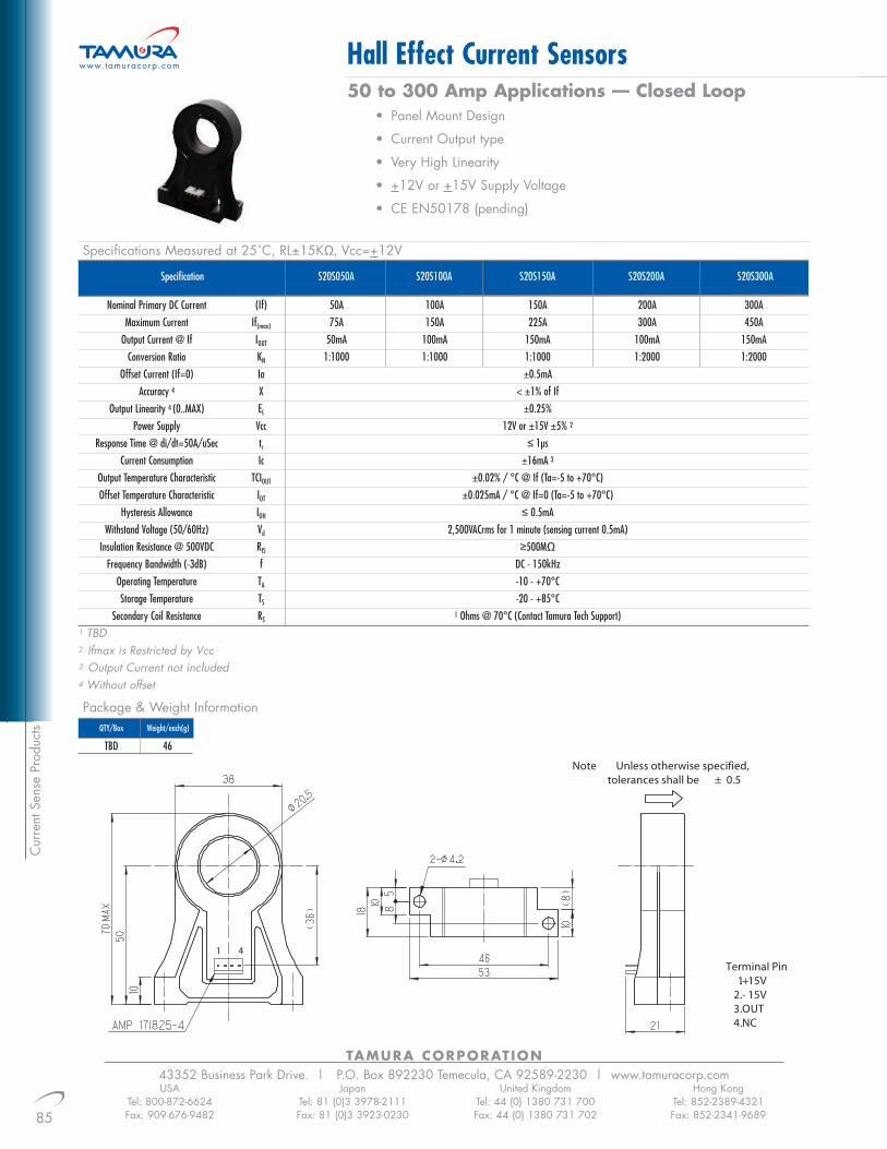
TAMURA CORPORATION43352 Business Park Drive. | P.O. Box 892230 Temecula, CA 92589-2230 | www.tamuracorp.com
85
Hall Effect Current Sensors
USATel: 800-872-6624Fax: 909-676-9482
JapanTel: 81 (0)3 3978-2111Fax: 81 (0)3 3923-0230
United KingdomTel: 44 (0) 1380 731 700Fax: 44 (0) 1380 731 702
Hong KongTel: 852-2389-4321Fax: 852-2341-9689
50 to 300 Amp Applications –– Closed Loop• Panel Mount Design
• Current Output type
• Very High Linearity
• +12V or +15V Supply Voltage
• CE EN50178 (pending)
www.tamuracorp.com
Cur
rent
Sen
se P
rodu
cts
Specification S20S100AS20S050A S20S150A S20S200A S20S300A
Nominal Primary DC Current (If) 50A 100A 150A 200A 300AMaximum Current If(max) 75A 150A 225A 300A 450A
Output Current @ If IOUT 50mA 100mA 150mA 100mA 150mAConversion Ratio KN 1:1000 1:1000 1:1000 1:2000 1:2000
Offset Current (If=0) Io ±0.5mAAccuracy 4 X < ±1% of If
Output Linearity 4 (0..MAX) EL ±0.25%Power Supply Vcc 12V or ±15V ±5% 2
Response Time @ di/dt=50A/uSec tr ≤ 1µsCurrent Consumption Ic ±16mA 3
Output Temperature Characteristic TCIOUT ±0.02% / °C @ If (Ta=-5 to +70°C)Offset Temperature Characteristic IOT ±0.025mA / °C @ If=0 (Ta=-5 to +70°C)
Hysteresis Allowance IOH ≤ 0.5mAWithstand Voltage (50/60Hz) Vd 2,500VACrms for 1 minute (sensing current 0.5mA)
Insulation Resistance @ 500VDC RIS ≥500MΩ
Frequency Bandwidth (-3dB) f DC - 150kHzOperating Temperature TA -10 - +70°CStorage Temperature TS -20 - +85°C
Secondary Coil Resistance RS1 Ohms @ 70°C (Contact Tamura Tech Support)
1 TBD2 Ifmax is Restricted by Vcc3 Output Current not included4 Without offset
Specifications Measured at 25˚C, RL±15KΩ, Vcc=+12V
Package & Weight Information
TBD 46
QTY/Box Weight/each(g)

86
TAMURA CORPORATION43352 Business Park Drive. | P.O. Box 892230 Temecula, CA 92589-2230 | www.tamuracorp.comUSA
Tel: 800-872-6624Fax: 909-676-9482
JapanTel: 81 (0)3 3978-2111Fax: 81 (0)3 3923-0230
United KingdomTel: 44 (0) 1380 731 700Fax: 44 (0) 1380 731 702
Hong KongTel: 852-2389-4321Fax: 852-2341-9689
Hall Effect Current Sensors6 to 25 Amp Applications –– Closed Loop
• Multirange Current Sensor
• Voltage Output
• Compact PCB Mount
• Single Supply (+5V)
• CE EN50178 (pending)
www.tamuracorp.com
Current Sense Products
Specification S22P015S05S22P006S05 S22P025S05
Nominal Primary r.m.s. Current (If) ±6A ±15A ±25AMaximum Current If(max) ±18A ±45A ±75A
Offset Voltage (If=0) VREF 2.5V±30mV 2.5V±20mV 2.5V±15mVOutput Voltage VOUT VREF ± 0.625V
Output Voltage Accuracy1 @ If X 0.625V ±10mVOutput Linearity (0 to If) EL ±0.25%
Power Supply Vcc ±5V±5%Response Time tr ≤1µs
Current Consumption IC 12.5mA Typ Output Temperature Characteristic ICEG ±0.05mV/°COffset Temperature Characteristic TCVOUT 1.25mV/°C 1.25mV/°C 1.25mV/°C
Hysteresis Allowance (If=0 to Ifmax) VOH ≤ 0.25mVWithstand Voltage (50/60Hz) Vd 3,000VACrms for 1 minute (sensing current 0.5mA)
Insulation Resistance @ 500VDC RIS ≥500MΩ
Operating Bandwidth (1dB) f DC - 200kHzOperating Temperature TA -10 - +85°CStorage Temperature TS -25 - +100°C
1 Without offset
Specifications Measured at 25˚C, RL-10KΩ, Vcc=+5V
Package & Weight Information
100 8
QTY/Box Weight/each(g)

TAMURA CORPORATION43352 Business Park Drive. | P.O. Box 892230 Temecula, CA 92589-2230 | www.tamuracorp.com
87
Current Sense Transformers
USATel: 800-872-6624Fax: 909-676-9482
JapanTel: 81 (0)3 3978-2111Fax: 81 (0)3 3923-0230
United KingdomTel: 44 (0) 1380 731 700Fax: 44 (0) 1380 731 702
Hong KongTel: 852-2389-4321Fax: 852-2341-9689
Up to 6 Amp Primary Current for High Frequency Applications• Surface mount and low profile design.
• Pick and place compatible.
• Designed to operate at 250kHz and above.
• Hipot 500Vrms between primary and secondary.
• Operating temperature: -40˚C to +85˚C.
www.tamuracorp.com
Cur
rent
Sen
se P
rodu
cts
Specifications Measured at 25˚C
Package & Weight Information
CALL CALL
QTY/Tape & Reel Weight/each(g)
TCS-01 1:20 80 6 0.55 20TCS-02 1:30 180 6 0.87 30TCS-03 1:40 320 6 1.14 40TCS-04 1:50 500 6 1.50 50TCS-05 1:60 720 6 1.75 60TCS-06 1:70 980 6 4.75 70TCS-07 1:100 2000 6 5.90 100TCS-08 1:125 3000 6 7.70 125
Part # Turns RationPri:Sec
DCRInductance (µH) MIN@ 10kHz, 0.1V Secondary Primary mΩ MAX Secondary mΩ MAX
Terminating Resistor (Ω) MAXSecondary
1 AboveTerminating Resistor Calculation based on 1 Volt/Ampere2 To calculate terminating resistor (RL )
RL = (V*N)/IWhere V - Output Voltage
I - Input CurrentN - Number of Secondary turns
Mechanical DimensionsAll dimensions are typical, please contact Tamura for tolerances and suggested layout information.

88
TAMURA CORPORATION43352 Business Park Drive. | P.O. Box 892230 Temecula, CA 92589-2230 | www.tamuracorp.comUSA
Tel: 800-872-6624Fax: 909-676-9482
JapanTel: 81 (0)3 3978-2111Fax: 81 (0)3 3923-0230
United KingdomTel: 44 (0) 1380 731 700Fax: 44 (0) 1380 731 702
Hong KongTel: 852-2389-4321Fax: 852-2341-9689
‘In-Line’ Switching Power Supplies www.tamuracorp.com
Switch M
ode Power Supplies
• Universal Input (90-264V) SMPS• Approved to UL/CSA, Excellent Thermal Management• Over Voltage and Thermal Protection• Highly Reliable Design• High Efficiency Design• Compact Packaging• Withstand Voltage of 3kV (input to output)• Very Low Standy Power (<0.8W)• FCC Class B Designs
Part # Output Ratings
VDC AmpsEfficiency1 (%)
Minimum Load(A)
Output Regulation(%)
Cooling MethodPackage Dimensions
mm(inches) TypL W H
PAA1228N72 12 2.8 84 0 ±5 Convection
PCW1240N72 12 4.0 85 0 ±5 Convection
PAA1628N72 16 2.8 84 0 ±5 Convection
PCW1637N72 16 3.8 85 0 ±5 Convection
PAA1923N72 19 2.4 85 0 ±5 Convection
PCW1931N72 19 3.2 85 0 ±5 Convection
PLW1947N72 19 4.8 83 0 ±5 Convection
PAA2418N72 24 1.9 85 0 ±5 Convection
PCW2425N72 24 2.5 85 0 ±5 Convection
90.00 43.50 26.50(3.543) (1.713) (1.043)110.00 45.00 29.00(4.331) (1.772) (1.142)90.00 43.50 26.50
(3.543) (1.713) (1.043)110.00 45.00 29.00(4.331) (1.772) (1.142)90.00 43.50 26.50
(3.543) (1.713) (1.043)110.00 45.00 29.00(4.331) (1.772) (1.142)133.00 58.00 31.15(5.236) (2.283) (1.226)90.00 43.50 26.50
(3.543) (1.713) (1.043)110.00 45.00 29.00(4.331) (1.772) (1.142)
1 Efficiency including cord loss2 Last number specifies OPC. Contact Tamura for OPC Options
W
L
H

TAMURA CORPORATION43352 Business Park Drive. | P.O. Box 892230 Temecula, CA 92589-2230 | www.tamuracorp.com
89
Micro Power Module
USATel: 800-872-6624Fax: 909-676-9482
JapanTel: 81 (0)3 3978-2111Fax: 81 (0)3 3923-0230
United KingdomTel: 44 (0) 1380 731 700Fax: 44 (0) 1380 731 702
Hong KongTel: 852-2389-4321Fax: 852-2341-9689
www.tamuracorp.com
Part #Input Voltage
(VDC) VDC mAmps
Output Ratings Output Frequency(kHz)
Fig.
uRM0520 120-375 5 400 44 A
uRM0530 120-375 5 600 130 A
uRM0550 120-375 5 1000 130 B
uRM0620 120-375 6 340 44 A
uRM0630 120-375 6 500 130 A
uRM0650 120-375 6 840 130 B
uRM1230 120-375 12 250 130 B
uRM1250 120-375 12 420 130 B
uRM1530 120-375 15 200 130 B
uRM1550 120-375 15 340 130 B
uRM151276-1 120 - 170 12 & 15 450 & 150 130 B
uRM151276-2 220 - 390 12 & 15 450 & 150 130 B
uRM151567-W 170 - 390 15 & 15 150 & 300 130 B
For Standby, Inverter Control & DC/DC Power Supplies• Approved to UL/CSA• Excellent Thermal Management• Vacuum Potted Design for Reliability and Durability• Short Circuit and Thermal Protection• Compact Space Saving Design• Reinforced Insulation = 3.5kV (Pri:Sec)
Switc
h M
ode
Pow
er S
uppl
ies
A

90
TAMURA CORPORATION43352 Business Park Drive. | P.O. Box 892230 Temecula, CA 92589-2230 | www.tamuracorp.comUSA
Tel: 800-872-6624Fax: 909-676-9482
JapanTel: 81 (0)3 3978-2111Fax: 81 (0)3 3923-0230
United KingdomTel: 44 (0) 1380 731 700Fax: 44 (0) 1380 731 702
Hong KongTel: 852-2389-4321Fax: 852-2341-9689
Micro Power Module www.tamuracorp.com
Switch M
ode Power Supplies
B
Example Circuit

91
TAMURA CORPORATION43352 Business Park Drive. | P.O. Box 892230 Temecula, CA 92589-2230 | www.tamuracorp.comUSA
Tel: 800-872-6624Fax: 909-676-9482
JapanTel: 81 (0)3 3978-2111Fax: 81 (0)3 3923-0230
United KingdomTel: 44 (0) 1380 731 700Fax: 44 (0) 1380 731 702
Hong KongTel: 852-2389-4321Fax: 852-2341-9689
Chassis Mount Power Supplieswww.tamuracorp.com
Part # Output Ratings
VDC AmpsEfficiency (%)
Leakage Current(mA) Cooling Method
RemoteON/OFF
Package Dimensionsmm(inches) Typ
L W H
EBS15-5 5 3.0 74 0.5 Convection NO
EBS30-5 5 6.0 77 0.5 Convection NO
EBS50-5 5 10.0 80 0.5 Convection NO
EBS75-5 5 15.0 81 0.5 Convection NO
EBS100-5 5 20.0 76 0.5 Convection NO
EBS15-12 12 1.3 78 0.5 Convection NO
EBS30-12 12 2.5 80 0.5 Convection NO
EBS50-12 12 4.3 82 0.5 Convection NO
EBS75-12 12 6.3 83 0.5 Convection NO
EBS100-12 12 9.0 82 0.5 Convection NO
EBS15-15 15 1.0 79 0.5 Convection NO
EBS30-15 15 2.0 82 0.5 Convection NO
EBS50-15 15 3.5 83 0.5 Convection NO
EBS75-15 15 5.0 84 0.5 Convection NO
EBS100-15 15 7.0 84 0.5 Convection NO
EBS15-24 24 0.7 80 0.5 Convection NO
EBS30-24 24 1.3 84 0.5 Convection NO
EBS50-24 24 2.5 84 0.5 Convection NO
EBS75-24 24 3.5 85 0.5 Convection NO
EBS100-24 24 5.0 87 0.5 Convection NO
115.0 50.0 16.0(4.528) (1.968) (0.630)132.5 50.0 24.0
(5.216) (1.968) (0.944)195.0 50.0 24.0
(7.677) (1.968) (0.944)222.0 50.0 31.0
(8.740) (1.968) (1.220)222.0 62.0 33.0
(8.740) (2.441) (1.299)115.0 50.0 16.0
(4.528) (1.968) (0.630)132.5 50.0 24.0
(5.216) (1.968) (0.944)195.0 50.0 24.0
(7.677) (1.968) (0.944)222.0 50.0 31.0
(8.740) (1.968) (1.220)222.0 62.0 33.0
(8.740) (2.441) (1.299)115.0 50.0 16.0
(4.528) (1.968) (0.630)132.5 50.0 24.0
(5.216) (1.968) (0.944)195.0 50.0 24.0
(7.677) (1.968) (0.944)222.0 50.0 31.0
(8.740) (1.968) (1.220)222.0 62.0 33.0
(8.740) (2.441) (1.299)115.0 50.0 16.0
(4.528) (1.968) (0.630)132.5 50.0 24.0
(5.216) (1.968) (0.944)195.0 50.0 24.0
(7.677) (1.968) (0.944)222.0 50.0 31.0
(8.740) (1.968) (1.220)222.0 62.0 33.0
(8.740) (2.441) (1.299)
L
W
H
• Input Voltage (85-132V)• Approved to UL/CSA, Excellent Thermal Management• Operating Temp = -10˚C to 50˚C• Highly Reliable Design• High Efficiency Design• Low Profile Designs• Withstand Voltage of 2kV (input to output)• FCC Class B Compliant
Switc
h M
ode
Pow
er S
uppl
ies

TAMURA CORPORATION43352 Business Park Drive. | P.O. Box 892230 Temecula, CA 92589-2230 | www.tamuracorp.com
92
Chassis Mount Power Supplies
USATel: 800-872-6624Fax: 909-676-9482
JapanTel: 81 (0)3 3978-2111Fax: 81 (0)3 3923-0230
United KingdomTel: 44 (0) 1380 731 700Fax: 44 (0) 1380 731 702
Hong KongTel: 852-2389-4321Fax: 852-2341-9689
www.tamuracorp.com
• Universal Input (90-264V) SMPS• Approved to UL/CSA, MITI and TUV• Excellent Thermal Management• Robust, Fault Tolerant Design• Highly Reliable Design• No overshoot during ON/OFF• Meets IEEE587 C62.41 Test• Withstand Voltage of 3kV (input to output)• Withstand Voltage of 1.5kV (output to chassis ground)
Part # Output Ratings
VDC AmpsEfficiency Min (%)
Leakage Current(mA)
Minimum Load(A)
Cooling MethodRemoteON/OFFControl
Package Dimensionsmm(inches) Typ
H W L W
OVS-5E-UC 5 10.0 70 0.75 0 Convection NO
OVS-5F-UC 5 20.0 70 0.75 0 Convection YES
OVS-5G-UC 5 30.0 70 0.75 0 Convection YES
OVS-5H-UC 5 45.0 70 0.75 0 Convection YES
OVS-5J-UC 5 60.0 70 0.75 0 Convection YES
OVS-12E-UC 12 5.0 70 0.75 0 Convection NO
OVS-12F-UC 12 10.0 70 0.75 0 Convection YES
OVS-12G-UC 12 15.0 70 0.75 0 Convection YES
OVS-12H-UC 12 22.0 70 0.75 0 Convection YES
OVS-12J-UC 12 30.0 70 0.75 0 Convection YES
OVS-24E-UC 24 2.5 70 0.75 0 Convection NO
OVS-24F-UC 24 5.0 70 0.75 0 Convection YES
OVS-24G-UC 24 8.0 70 0.75 0 Convection YES
OVS-24H-UC 24 12.0 70 0.75 0 Convection YES
OVS-24J-UC 24 16.0 70 0.75 0 Convection YES
50.8 124.0 117.3(2.00) (4.88) (4.62)60.2 124.0 180.3
(2.37) (4.88) (7.10)60.2 124.0 218.4
(2.37) (4.88) (8.60)66.0 124.0 269.2
(2.60) (4.88) (10.60)69.9 124.0 304.8
(2.75) (4.88) (12.00)50.8 124.0 117.3
(2.00) (4.88) (4.62)60.2 124.0 180.3
(2.37) (4.88) (7.10)60.2 124.0 218.4
(2.37) (4.88) (8.60)66.0 124.0 269.2
(2.60) (4.88) (10.60)69.9 124.0 304.8
(2.75) (4.88) (12.00)50.8 124.0 117.3
(2.00) (4.88) (4.62)60.2 124.0 180.3
(2.37) (4.88) (7.10)60.2 124.0 218.4
(2.37) (4.88) (8.60)66.0 124.0 269.2
(2.60) (4.88) (10.60)69.9 124.0 304.8
(2.75) (4.88) (12.00)
L
W
H
Switch M
ode Power Supplies

Switc
h M
ode
Pow
er S
uppl
ies
93
TAMURA CORPORATION43352 Business Park Drive. | P.O. Box 892230 Temecula, CA 92589-2230 | www.tamuracorp.comUSA
Tel: 800-872-6624Fax: 909-676-9482
JapanTel: 81 (0)3 3978-2111Fax: 81 (0)3 3923-0230
United KingdomTel: 44 (0) 1380 731 700Fax: 44 (0) 1380 731 702
Hong KongTel: 852-2389-4321Fax: 852-2341-9689
Cell Power Supplieswww.tamuracorp.com
Part # Max. Input Current (A)
115V 240V
Max. Inrush Current(A)
Efficiency Typ.(%)
Leakage Current(mA)
Cooling MethodRemoteON/OFFControl
MRS600 10 5 35 78 0.95 FAN YES
Part # Output Ratings
VDC Amps (Max)
Output Ripple(mV)
Line Regulation(%)
Load Regulation(%)
Total Regulation(%)
RemoteSensing
OutputFailure
Detection
RemoteON/OFFControl
MFS120-3 3.0 - 3.6 24 100 ±1 ±2 ±5 YES YES YES
MFS120-5 4.5 - 5.5 24 100 ±1 ±2 ±5 YES YES YES
MVS120-12 5.0 - 15.0 10 240 ±1 ±2 ±5 YES YES YES
MVS120-24 18.0 - 30.0 5 480 ±1 ±2 ±5 YES YES YES
MVD50-12D5.0 - 15.0 4.2 240 ±1 ±2 ±5 NO NO NO
5.0 - 15.0 4.2 240 ±1 ±2 ±5 NO NO NO
MVD50-1225.0 - 15.0 4.2 240 ±1 ±2 ±5 NO NO NO
18.0 - 30.0 2.1 480 ±1 ±2 ±5 NO NO NO
MVD50-24D18.0 - 30.0 2.1 480 ±1 ±2 ±5 NO NO NO
18.0 - 30.0 2.1 480 ±1 ±2 ±5 NO NO NO
• Universal Input (85-264V)• Designed to Meet EN60950• Complies with EN55022-B, FCC-B• Input Filter and PFC Included• Operating Temp. = 0˚C to 60˚C• Easy Maintenance• Remote ON/OFF• Adjustable Output Voltage• Maximum 600 Watts
Modular Output (Cell) Units

TAMURA CORPORATION43352 Business Park Drive. | P.O. Box 892230 Temecula, CA 92589-2230 | www.tamuracorp.com
94
Linear Wall Plug Adapters
USATel: 800-872-6624Fax: 909-676-9482
JapanTel: 81 (0)3 3978-2111Fax: 81 (0)3 3923-0230
United KingdomTel: 44 (0) 1380 731 700Fax: 44 (0) 1380 731 702
Hong KongTel: 852-2389-4321Fax: 852-2341-9689
www.tamuracorp.com
Wall Plug A
dapters
AC and DC Output Versions with Output Cord• Approved to UL1310 & cUL
• Operating Temp = -10˚C to +40˚C
• Withstand Voltage = 1,500V (input to output)
• High Quality Robust Designs
• Class II Transformer
Part # VoltsRated Output at 100% Load
mAOutput Type
(AC/DC)212AS03032 3.0 320 DC318AS03100 3.0 1000 DC830AS03175 3.0 1750 DC212AS04025 4.5 250 DC318AS04070 4.5 700 DC420AS04100 4.5 1000 DC830AS04150 4.5 1500 DC212AS06020 6.0 200 DC318AS06050 6.0 500 DC420AS06090 6.0 900 DC830AS06125 6.0 1250 DC212AS09012 9.0 125 DC318AS09035 9.0 350 DC420AS09060 9.0 600 DC830AS09100 9.0 1000 DC835AS09140 9.0 1400 DC212AS12010 12.0 100 DC318AS12030 12.0 300 DC420AS12050 12.0 500 DC830AS12080 12.0 800 DC835AS12100 12.0 1000 DC212AS15007 15.0 75 DC318AS15025 15.0 250 DC420AS15040 15.0 400 DC830AS15070 15.0 700 DC835AS15080 15.0 800 DC212AS18006 18.0 60 DC318AS18020 18.0 200 DC420AS18035 18.0 350 DC830AS18060 18.0 600 DC835AS18070 18.0 700 DC212AS24005 24.0 50 DC318AS24015 24.0 150 DC420AS24025 24.0 250 DC830AS24045 24.0 450 DC835AS24050 24.0 500 DC212AS12012 12.0 125 AC318AS12037 12.0 375 AC420AS12075 12.0 750 AC830AS12100 12.0 1000 AC835AS12150 12.0 1500 AC212AS16010 16.0 100 AC318AS16030 16.0 300 AC420AS16056 16.0 560 AC830AS16090 16.0 900 AC835AS16112 16.0 1125 AC212AS20007 20.0 75 AC318AS20022 20.0 225 AC420AS20045 20.0 450 AC830AS20080 20.0 800 AC835AS20090 20.0 900 AC212AS24006 24.0 60 AC318AS24020 24.0 200 AC420AS24037 24.0 375 AC830AS24070 24.0 700 AC835AS24075 24.0 750 AC
Mechanical Dimension TableSERIES LENGTH(L) WIDTH(W) HEIGHT(HPREFIX MM(INCH) MM (INCH) MM(INCH)212AS 64 (2.51) 40 (1.57) 36 (1.42)318AS 70 (2.75) 46 (1.81) 43 (1.69)420AS 72 (2.83) 52 (2.54) 47 (1.85)830AS 91 (3.58) 58 (2.28) 52 (2.07)835AS 103 (4.05) 62 (2.44) 62 (2.44)
FEMALE
L
D1D2
PLUG DI D2 L GENDERTYPE (mm) (mm) (mm)
D 5.5 2.10 12.5 FEMALE
OUTPUT PLUG DIMENSIONS
1 Typical output voltage for % load (FL) and line (VAC) indicated.
2 UL: UL1310 LISTE DUL*: UL1310 LISTING WITH UL1411C: UL Approved for battery charger ckts (contact battery mfgr for recommended volt.)
3 Complies (C) with or is listed (L) to CSA C22.2, No. 223.664 CUL : UL1310 listed for use in Canada
L
H
W
Notes

Wal
l Plu
g A
dapt
ers
95
TAMURA CORPORATION43352 Business Park Drive. | P.O. Box 892230 Temecula, CA 92589-2230 | www.tamuracorp.comUSA
Tel: 800-872-6624Fax: 909-676-9482
JapanTel: 81 (0)3 3978-2111Fax: 81 (0)3 3923-0230
United KingdomTel: 44 (0) 1380 731 700Fax: 44 (0) 1380 731 702
Hong KongTel: 852-2389-4321Fax: 852-2341-9689
Linear Wall Plug Adapterswww.tamuracorp.com
AC Output with Screw Terminal Connections• Approved to UL1310 & CSA• Operating Temp = 0˚C to +40˚C• Withstand Voltage = 1,500V (input to output)• High Quality Robust Design• Class II Transformer• Inherently Limited Design
Part # VoltsRated Output at 100% Load
mAOutput Type
(AC/DC)820A0060-03 10 1200 AC
820A0061-03 12 1000 AC
820A0062-03 14 850 AC
820A0063-03 16 750 AC
820A0064-03 18 650 AC
820A0065-03 20 600 AC
820A0066-03 22 550 AC
820A0067-03 24 500 AC
830A0060-03 10 2000 AC
830A0061-03 12 1600 AC
830A0062-03 14 1430 AC
830A0063-03 16 1250 AC
830A0064-03 18 1110 AC
830A0065-03 20 1000 AC
830A0066-03 22 900 AC
830A0067-03 24 830 AC
Mechanical Dimension TableSERIES LENGTH(L) WIDTH(W) HEIGHT(HPREFIX MM(INCH) MM (INCH) MM(INCH)
820A-03 75 (2.95) 63 (2.48) 50 (1.97)830A-03 75 (2.95) 63 (2.48) 50 (1.97
W
H
L

Euro, N. America, and Japan Plugs with Control Signal Feed Through
• Approved to Appropriate Agency
• Operating Temp = 0˚C to +40˚C
• Inherently Limited Designs
• High Quality Robust Design
® LonWorks® is a registered trademark for Echelon Corporation
TAMURA CORPORATION43352 Business Park Drive. | P.O. Box 892230 Temecula, CA 92589-2230 | www.tamuracorp.com
96
LonWorks® Linear Wall PLug Adapters
USATel: 800-872-6624Fax: 909-676-9482
JapanTel: 81 (0)3 3978-2111Fax: 81 (0)3 3923-0230
United KingdomTel: 44 (0) 1380 731 700Fax: 44 (0) 1380 731 702
Hong KongTel: 852-2389-4321Fax: 852-2341-9689
www.tamuracorp.com
Wall Plug A
dapters
Part #Rated Output at
100% LoadVolts mA
Output Type(AC/DC)
AC Input Case and InputPlug Fig.
Dimensions
H W L
420A12150P 12.5 150 DC 117V@60Hz B
420F12150P 12.5 150 DC 230V@50Hz A
425A12400P 12.5 400 DC 120V@60Hz B
425F12400P 12.5 400 DC 230V@50/60Hz A
425J12400P 12.5 400 DC 120V@50/60Hz B
50.0 52.0 83.0(1.969) (2.047) (3.268)
46.0 58.0 88.0(1.811) (2.285) (3.465)43.50 58.0 88.0
(1.713) (2.285) (3.465)46.0 58.0 88.0
(1.811) (2.285) (3.465)43.50 58.0 88.0
(1.713) (2.285) (3.465)
LL
A B
WW
HH
VAC IN
Vout
Mechanical DimensionsPlease contact Tamura for tolerances information.
Schematics

Inde
x
TAMURA CORPORATION43352 Business Park Drive. | P.O. Box 892230 Temecula, CA 92589-2230 | www.tamuracorp.com
97
Product Index
USATel: 800-872-6624Fax: 909-676-9482
JapanTel: 81 (0)3 3978-2111Fax: 81 (0)3 3923-0230
United KingdomTel: 44 (0) 1380 731 700Fax: 44 (0) 1380 731 702
Hong KongTel: 852-2389-4321Fax: 852-2341-9689
www.tamuracorp.com
212AS03032 . . . . . . .94
212AS04025 . . . . . . .94
212AS06020 . . . . . . .94
212AS09012 . . . . . . .94
212AS12010 . . . . . . .94
212AS12012 . . . . . . .94
212AS15007 . . . . . . .94
212AS16010 . . . . . . .94
212AS18006 . . . . . . .94
212AS20007 . . . . . . .94
212AS24005 . . . . . . .94
212AS24006 . . . . . . .94
318AS03100 . . . . . . .94
318AS04070 . . . . . . .94
318AS06050 . . . . . . .94
318AS09035 . . . . . . .94
318AS12030 . . . . . . .94
318AS12037 . . . . . . .94
318AS15025 . . . . . . .94
318AS16030 . . . . . . .94
318AS18020 . . . . . . .94
318AS20022 . . . . . . .94
318AS24015 . . . . . . .94
318AS24020 . . . . . . .94
3FD-210 . . . . . . . . . .3
3FD-212 . . . . . . . . . .3
3FD-216 . . . . . . . . . .3
3FD-220 . . . . . . . . . .3
3FD-224 . . . . . . . . . .3
3FD-228 . . . . . . . . . .3
3FD-236 . . . . . . . . . .3
3FD-248 . . . . . . . . . .3
3FD-310 . . . . . . . . . .3
3FD-312 . . . . . . . . . .3
3FD-316 . . . . . . . . . .3
3FD-320 . . . . . . . . . .3
3FD-324 . . . . . . . . . .3
3FD-328 . . . . . . . . . .3
3FD-336 . . . . . . . . . .3
3FD-348 . . . . . . . . . .3
3FD-410 . . . . . . . . . .3
3FD-412 . . . . . . . . . .3
3FD-416 . . . . . . . . . .3
3FD-420 . . . . . . . . . .3
3FD-424 . . . . . . . . . .3
3FD-428 . . . . . . . . . .3
3FD-436 . . . . . . . . . .3
3FD-448 . . . . . . . . . .3
3FD-510 . . . . . . . . . .3
3FD-512 . . . . . . . . . .3
3FD-516 . . . . . . . . . .3
3FD-520 . . . . . . . . . .3
3FD-524 . . . . . . . . . .3
3FD-528 . . . . . . . . . .3
3FD-536 . . . . . . . . . .3
3FD-548 . . . . . . . . . .3
3FL10-1200 . . . . . . . .5
3FL10-250 . . . . . . . . .5
3FL10-600 . . . . . . . . .5
3FL120-100 . . . . . . . .5
3FL120-20 . . . . . . . . .5
3FL120-50 . . . . . . . . .5
3FL12-200 . . . . . . . . .5
3FL12-475 . . . . . . . . .5
3FL12-950 . . . . . . . . .5
3FL16-150 . . . . . . . . .5
3FL16-350 . . . . . . . . .5
3FL16-700 . . . . . . . . .5
3FL20-125 . . . . . . . . .5
3FL20-300 . . . . . . . . .5
3FL20-600 . . . . . . . . .5
3FL230-10 . . . . . . . . .5
3FL230-25 . . . . . . . . .5
3FL230-50 . . . . . . . . .5
3FL24-100 . . . . . . . . .5
3FL24-250 . . . . . . . . .5
3FL24-500 . . . . . . . . .5
3FL30-200 . . . . . . . . .5
3FL30-400 . . . . . . . . .5
3FL30-85 . . . . . . . . . .5
3FL34-170 . . . . . . . . .5
3FL34-340 . . . . . . . . .5
3FL34-75 . . . . . . . . . .5
3FL40-150 . . . . . . . . .5
3FL40-300 . . . . . . . . .5
3FL40-60 . . . . . . . . . .5
3FL56-100 . . . . . . . . .5
3FL56-200 . . . . . . . . .5
3FL56-45 . . . . . . . . . .5
3FL88-130 . . . . . . . . .5
3FL88-28 . . . . . . . . . .5
3FL88-65 . . . . . . . . . .5
3FS-210 . . . . . . . . . . .3
3FS-212 . . . . . . . . . . .3
3FS-216 . . . . . . . . . . .3
3FS-220 . . . . . . . . . . .3
3FS-224 . . . . . . . . . . .3
3FS-228 . . . . . . . . . . .3
3FS-236 . . . . . . . . . . .3
3FS-248 . . . . . . . . . . .3
3FS-310 . . . . . . . . . . .3
3FS-312 . . . . . . . . . . .3
3FS-316 . . . . . . . . . . .3
3FS-320 . . . . . . . . . . .3
3FS-324 . . . . . . . . . . .3
3FS-328 . . . . . . . . . . .3
3FS-336 . . . . . . . . . . .3
3FS-348 . . . . . . . . . . .3
3FS-410 . . . . . . . . . . .3
3FS-412 . . . . . . . . . . .3
3FS-416 . . . . . . . . . . .3
3FS-420 . . . . . . . . . . .3
3FS-424 . . . . . . . . . . .3
3FS-428 . . . . . . . . . . .3
3FS-436 . . . . . . . . . . .3
3FS-448 . . . . . . . . . . .3
3FS-510 . . . . . . . . . . .3
3FS-512 . . . . . . . . . . .3
3FS-516 . . . . . . . . . . .3
3FS-520 . . . . . . . . . . .3
3FS-524 . . . . . . . . . . .3
3FS-528 . . . . . . . . . . .3
3FS-536 . . . . . . . . . . .3
3FS-548 . . . . . . . . . . .3
420A1215P . . . . . . . .96
420AS04100 . . . . . . .94
420AS06090 . . . . . . .94
420AS09060 . . . . . . .94
420AS12050 . . . . . . .94
420AS12075 . . . . . . .94
420AS15040 . . . . . . .94
420AS16056 . . . . . . .94
420AS18035 . . . . . . .94
420AS20045 . . . . . . .94
420AS24025 . . . . . . .94
420AS24037 . . . . . . .94
420F12150P . . . . . . .96
425A12400P . . . . . . .96
425F12400P . . . . . . .96
425J12400P . . . . . . .96
820A0060-03 . . . . . .95
820A0061-03 . . . . . .95
820A0062-03 . . . . . .95
820A0063-03 . . . . . .95
820A0064-03 . . . . . .95
820A0065-03 . . . . . .95
820A0066-03 . . . . . .95
820A0067-03 . . . . . .95

Index
98
TAMURA CORPORATION43352 Business Park Drive. | P.O. Box 892230 Temecula, CA 92589-2230 | www.tamuracorp.comUSA
Tel: 800-872-6624Fax: 909-676-9482
JapanTel: 81 (0)3 3978-2111Fax: 81 (0)3 3923-0230
United KingdomTel: 44 (0) 1380 731 700Fax: 44 (0) 1380 731 702
Hong KongTel: 852-2389-4321Fax: 852-2341-9689
Product Index www.tamuracorp.com
830A0060-03 . . . . . .95
830A0061-03 . . . . . .95
830A0062-03 . . . . . .95
830A0063-03 . . . . . .95
830A0064-03 . . . . . .95
830A0065-03 . . . . . .95
830A0066-03 . . . . . .95
830A0067-03 . . . . . .95
830AS03175 . . . . . . .94
830AS04150 . . . . . . .94
830AS06125 . . . . . . .94
830AS09100 . . . . . . .94
830AS12080 . . . . . . .94
830AS12100 . . . . . . .94
830AS15070 . . . . . . .94
830AS16090 . . . . . . .94
830AS18060 . . . . . . .94
830AS20080 . . . . . . .94
830AS24045 . . . . . . .94
830AS24070 . . . . . . .94
835AS09140 . . . . . . .94
835AS12100 . . . . . . .94
835AS12150 . . . . . . .94
835AS15080 . . . . . . .94
835AS16112 . . . . . . .94
835AS18070 . . . . . . .94
835AS20090 . . . . . . .94
835AS24050 . . . . . . .94
835AS24075 . . . . . . .94
EBS100-12 . . . . . . . . .91
EBS100-15 . . . . . . . . .91
EBS100-24 . . . . . . . . .91
EBS100-5 . . . . . . . . . .91
EBS15-12 . . . . . . . . . .91
EBS15-15 . . . . . . . . . .91
EBS15-24 . . . . . . . . . .91
EBS15-5 . . . . . . . . . . .91
EBS30-12 . . . . . . . . . .91
EBS30-15 . . . . . . . . . .91
EBS30-24 . . . . . . . . . .91
EBS30-5 . . . . . . . . . . .91
EBS50-12 . . . . . . . . . .91
EBS50-15 . . . . . . . . . .91
EBS50-24 . . . . . . . . . .91
EBS50-5 . . . . . . . . . . .91
EBS75-12 . . . . . . . . . .91
EBS75-15 . . . . . . . . . .91
EBS75-24 . . . . . . . . . .91
EBS75-5 . . . . . . . . . . .91
G500 . . . . . . . . . . . .20
G501 . . . . . . . . . . . .20
G502 . . . . . . . . . . . .20
G503 . . . . . . . . . . . .20
G505 . . . . . . . . . . . .20
G506 . . . . . . . . . . . .20
G507 . . . . . . . . . . . .20
G508 . . . . . . . . . . . .20
G509 . . . . . . . . . . . .20
G510 . . . . . . . . . . . .20
G511 . . . . . . . . . . . .20
G512 . . . . . . . . . . . .20
G513 . . . . . . . . . . . .20
G514 . . . . . . . . . . . .20
G515 . . . . . . . . . . . .20
G516 . . . . . . . . . . . .20
G517 . . . . . . . . . . . .20
G553 . . . . . . . . . . . .20
G557 . . . . . . . . . . . .20
G700 . . . . . . . . . . . .20
G701 . . . . . . . . . . . .20
HBL-0244 . . . . . . . . . .72
HBL-0268 . . . . . . . . . .72
HBL-0269 . . . . . . . . . .72
HBL-0270 . . . . . . . . . .72
HBL-0293 . . . . . . . . . .72
HBL-0510 . . . . . . . . . .73
L01Z050S05 . . . . . . .83
L01Z100S05 . . . . . . .83
L01Z150S05 . . . . . . .83
L01Z200S05 . . . . . . .83
L01Z300S05 . . . . . . .83
L01Z400S05 . . . . . . .83
L01Z500S05 . . . . . . .83
L01Z600S05 . . . . . . .83
L03S050D15 . . . . . . .82
L03S100D15 . . . . . . .82
L03S200D15 . . . . . . .82
L03S300D15 . . . . . . .82
L03S400D15 . . . . . . .82
L03S500D15 . . . . . . .82
L03S600D15 . . . . . . .82
L08P050D15 . . . . . . .81
L08P100D15 . . . . . . .81
L08P150D15 . . . . . . .81
L08P200D15 . . . . . . .81
L10P003D15 . . . . . . .77
L10P003S05 . . . . . . .78
L10P003S12 . . . . . . .79
L10P005D15 . . . . . . .77
L10P005S05 . . . . . . .78
L10P005S12 . . . . . . .79
L10P010D15 . . . . . . .77
L10P010S05 . . . . . . .78
L10P010S12 . . . . . . .79
L10P015D15 . . . . . . .77
L10P015S05 . . . . . . .78
L10P015S12 . . . . . . .79
L10P020D15 . . . . . . .77
L10P020S05 . . . . . . .78
L10P020S12 . . . . . . .79
L10P025D15 . . . . . . .77
L10P025S05 . . . . . . .78
L10P025S12 . . . . . . .79
L10P030D15 . . . . . . .77
L10P030S05 . . . . . . .78
L10P030S12 . . . . . . .79
L16P003D15 . . . . . . .80
L16P005D15 . . . . . . .80
L16P010D15 . . . . . . .80
L16P015D15 . . . . . . .80
L16P020D15 . . . . . . .80
L16P025D15 . . . . . . .80
MET-01 . . . . . . . . . . .30
MET-05 . . . . . . . . . . .30
MET-09 . . . . . . . . . . .30
MET-11 . . . . . . . . . . .30
MET-17 . . . . . . . . . . .30
MET-23 . . . . . . . . . . .30
MET-24 . . . . . . . . . . .30
MET-28 . . . . . . . . . . .30
MET-31 . . . . . . . . . . .30
MET-32 . . . . . . . . . . .30
MET-35 . . . . . . . . . . .30
MET-39 . . . . . . . . . . .30
MET-42 . . . . . . . . . . .30
MET-46 . . . . . . . . . . .30
MET-50 . . . . . . . . . . .30
MET-59 . . . . . . . . . . .30
MET-60 . . . . . . . . . . .30
METC-99 . . . . . . . . . .30
MFS120-3 . . . . . . . . .93
MFS120-5 . . . . . . . . .93
MRS600 . . . . . . . . . .93
MVD50-122 . . . . . . . .93
MVD50-12D . . . . . . . .93
MVD50-24D . . . . . . . .93
MVS120-12 . . . . . . . .93
MVS120-24 . . . . . . . .93

Inde
x
TAMURA CORPORATION43352 Business Park Drive. | P.O. Box 892230 Temecula, CA 92589-2230 | www.tamuracorp.com
99
Product Index
USATel: 800-872-6624Fax: 909-676-9482
JapanTel: 81 (0)3 3978-2111Fax: 81 (0)3 3923-0230
United KingdomTel: 44 (0) 1380 731 700Fax: 44 (0) 1380 731 702
Hong KongTel: 852-2389-4321Fax: 852-2341-9689
www.tamuracorp.com
MX-52 . . . . . . . . . . . .29
MX-58 . . . . . . . . . . . .29
MX-59 . . . . . . . . . . . .29
MX-61 . . . . . . . . . . . .29
OVS-12E-UC . . . . . . . .92
OVS-12F-UC . . . . . . . .92
OVS-12G-UC . . . . . . .92
OVS-12H-UC . . . . . . .92
OVS-12J-UC . . . . . . . .92
OVS-24E-UC . . . . . . . .92
OVS-24F-UC . . . . . . . .92
OVS-24G-UC . . . . . . .92
OVS-24H-UC . . . . . . .92
OVS-24J-UC . . . . . . . .92
OVS-5E-UC . . . . . . . . .92
OVS-5F-UC . . . . . . . . .92
OVS-5G-UC . . . . . . . .92
OVS-5H-UC . . . . . . . .92
OVS-5J-UC . . . . . . . . .92
PAA1228N7 . . . . . . .88
PAA1628N7 . . . . . . .88
PAA1923N7 . . . . . . .88
PAA2418N7 . . . . . . .88
PCW1240N7 . . . . . . .88
PCW1637N7 . . . . . . .88
PCW1931N7 . . . . . . .88
PCW2425N7 . . . . . . .88
PF24-10 . . . . . . . . . . .5
PF24-12 . . . . . . . . . . .5
PF24-16 . . . . . . . . . . .5
PF24-20 . . . . . . . . . . .5
PF24-24 . . . . . . . . . . .5
PF24-30 . . . . . . . . . . .5
PF24-34 . . . . . . . . . . .5
PF24-56 . . . . . . . . . . .5
PL0PUE . . . . . . . . . . .24
PL10-10-130B . . . . . . .2
PL10-12-130B . . . . . . .2
PL10-16-130B . . . . . . .2
PL10-20-130B . . . . . . .2
PL10-24-130B . . . . . . .2
PL10-28-130B . . . . . . .2
PL10-36-130B . . . . . . .2
PL2.5-10-130B . . . . . .2
PL2.5-12-130B . . . . . .2
PL2.5-16-130B . . . . . .2
PL2.5-20-130B . . . . . .2
PL2.5-24-130B . . . . . .2
PL2.5-28-130B . . . . . .2
PL2.5-36-130B . . . . . .2
PL20-10-130B . . . . . . .2
PL20-12-130B . . . . . . .2
PL20-16-130B . . . . . . .2
PL20-20-130B . . . . . . .2
PL20-24-130B . . . . . . .2
PL20-28-130B . . . . . . .2
PL20-36-130B . . . . . . .2
PL30-10-130B . . . . . . .2
PL30-12-130B . . . . . . .2
PL30-16-130B . . . . . . .2
PL30-20-130B . . . . . . .2
PL30-24-130B . . . . . . .2
PL30-28-130B . . . . . . .2
PL30-36-130B . . . . . . .2
PL5.0-10-130B . . . . . .2
PL5.0-12-130B . . . . . .2
PL5.0-16-130B . . . . . .2
PL5.0-20-130B . . . . . .2
PL5.0-24-130B . . . . . .2
PL5.0-28-130B . . . . . .2
PL5.0-36-130B . . . . . .2
PL56-10-130B . . . . . . .2
PL56-12-130B . . . . . . .2
PL56-16-130B . . . . . . .2
PL56-20-130B . . . . . . .2
PL56-24-130B . . . . . . .2
PL56-28-130B . . . . . . .2
PL56-36-130B . . . . . . .2
PLP01 . . . . . . . . . . . .24
PLW1947N7 . . . . . . .88
S20S050A . . . . . . . . .85
S20S100A . . . . . . . . .85
S20S150A . . . . . . . . .85
S20S200A . . . . . . . . .85
S20S300A . . . . . . . . .85
S21Z100D15 . . . . . . .84
S21Z150D15 . . . . . . .84
S21Z200D15 . . . . . . .84
S21Z300D15 . . . . . . .84
S22P006S05 . . . . . . .86
S22P015S05 . . . . . . .86
S22P025S05 . . . . . . .86
SB2812-1204 . . . . . .4
SB2812-1206 . . . . . .4
SB2812-1210 . . . . . .4
SB2812-1214 . . . . . .4
SB2812-1216 . . . . . .4
SB2812-1218 . . . . . .4
SB2812-1222 . . . . . .4
SB2812-1224 . . . . . .4
SB2812-1226 . . . . . .4
SB2812-1230 . . . . . .4
SB2816-1604 . . . . . .4
SB2816-1606 . . . . . .4
SB2816-1610 . . . . . .4
SB2816-1614 . . . . . .4
SB2816-1616 . . . . . .4
SB2816-1618 . . . . . .4
SB2816-1622 . . . . . .4
SB2816-1624 . . . . . .4
SB2816-1626 . . . . . .4
SB2816-1630 . . . . . .4
SB3512-2004 . . . . . .4
SB3512-2006 . . . . . .4
SB3512-2010 . . . . . .4
SB3512-2014 . . . . . .4
SB3512-2016 . . . . . .4
SB3512-2018 . . . . . .4
SB3512-2022 . . . . . .4
SB3512-2024 . . . . . .4
SB3512-2026 . . . . . .4
SB3512-2030 . . . . . .4
SB3516-3004 . . . . . .4
SB3516-3006 . . . . . .4
SB3516-3010 . . . . . .4
SB3516-3014 . . . . . .4
SB3516-3016 . . . . . .4
SB3516-3018 . . . . . .4
SB3516-3022 . . . . . .4
SB3516-3024 . . . . . .4
SB3516-3026 . . . . . .4
SB3516-3030 . . . . . .4
TBL4535D-28HB . . . . .75
TBL4535D-28HN . . . .75
TBL4535D-40HB . . . . .75
TBL4535D-40HN . . . .75
TBL6035D-28HN . . . .75
TBLE1507 . . . . . . . . .74
TBLE3015 . . . . . . . . .74
TBLE3515 . . . . . . . . .74
TBLE5023 . . . . . . . . .74
TBLE6030 . . . . . . . . .74
TBLE7032 . . . . . . . . .74
TCS-01 . . . . . . . . . . .87
TCS-02 . . . . . . . . . . .87
TCS-03 . . . . . . . . . . .87
TCS-04 . . . . . . . . . . .87
TCS-05 . . . . . . . . . . .87

Index
100
TAMURA CORPORATION43352 Business Park Drive. | P.O. Box 892230 Temecula, CA 92589-2230 | www.tamuracorp.comUSA
Tel: 800-872-6624Fax: 909-676-9482
JapanTel: 81 (0)3 3978-2111Fax: 81 (0)3 3923-0230
United KingdomTel: 44 (0) 1380 731 700Fax: 44 (0) 1380 731 702
Hong KongTel: 852-2389-4321Fax: 852-2341-9689
Product Index www.tamuracorp.com
TCS-06 . . . . . . . . . . .87
TCS-07 . . . . . . . . . . .87
TCS-08 . . . . . . . . . . .87
TDSE20 . . . . . . . . . . .74
TDSE25 . . . . . . . . . . .74
TDSE28 . . . . . . . . . . .74
TDSE40 . . . . . . . . . . .74
TDSE43 . . . . . . . . . . .74
TDSE70 . . . . . . . . . . .74
TIC-G001-21 . . . . . . .67
TIC-G002-21 . . . . . . .67
TIC-G003-21 . . . . . . .67
TIC-G004-21 . . . . . . .67
TIC-G005-21 . . . . . . .67
TIC-G006-21 . . . . . . .67
TIC-G007-21 . . . . . . .67
TIC-G008-21 . . . . . . .67
TIC-G009-21 . . . . . . .67
TIC-G010-21 . . . . . . .67
TIC-G011-21 . . . . . . .67
TIC-G012-21 . . . . . . .67
TIC-G013-21 . . . . . . .67
TIC-G014-21 . . . . . . .67
TIC-G015-21 . . . . . . .67
TIC-G016-21 . . . . . . .67
TIC-G017-21 . . . . . . .67
TIC-G018-21 . . . . . . .67
TIC-L001-11 . . . . . . . .51
TIC-L002-11 . . . . . . . .51
TIC-L003-11 . . . . . . . .51
TIC-L004-11 . . . . . . . .51
TIC-L005-14 . . . . . . . .55
TIC-L006-11 . . . . . . . .51
TIC-L007-11 . . . . . . . .51
TIC-L008-11 . . . . . . . .51
TIC-L009-11 . . . . . . . .51
TIC-L010-11 . . . . . . . .51
TIC-L011-11 . . . . . . . .51
TIC-L012-11 . . . . . . . .51
TIC-L013-11 . . . . . . . .51
TIC-L014-11 . . . . . . . .51
TIC-L015-11 . . . . . . . .51
TIC-L016-14 . . . . . . . .55
TIC-L017-14 . . . . . . . .55
TIC-L018-14 . . . . . . . .55
TIC-L019-16 . . . . . . . .61
TIC-L020-24 . . . . . . . .63
TIC-L021-24 . . . . . . . .63
TIC-L022-24 . . . . . . . .63
TIC-L023-24 . . . . . . . .63
TIC-L024-24 . . . . . . . .63
TIC-L025-11 . . . . . . . .59
TIC-L026-11 . . . . . . . .59
TIC-L027-11 . . . . . . . .59
TIC-L028-11 . . . . . . . .59
TIC-L029-11 . . . . . . . .59
TIC-L030-11 . . . . . . . .59
TIC-L031-11 . . . . . . . .59
TIC-L032-11 . . . . . . . .59
TIC-L033-11 . . . . . . . .47
TIC-L034-11 . . . . . . . .47
TIC-L035-11 . . . . . . . .47
TIC-L036-11 . . . . . . . .47
TIC-L037-11 . . . . . . . .47
TIC-L038-11 . . . . . . . .47
TIC-L039-11 . . . . . . . .47
TIC-L040-11 . . . . . . . .47
TIC-L041-11 . . . . . . . .65
TIC-L042-11 . . . . . . . .45
TIC-L044-14 . . . . . . . .55
TIC-L047-11 . . . . . . . .65
TIC-L048-11 . . . . . . . .65
TIC-L050-14 . . . . . . . .55
TIC-L058-11 . . . . . . . .47
TIC-L062-11 . . . . . . . .45
TIC-L063-11 . . . . . . . .45
TIC-L065-16 . . . . . . . .61
TIC-L066-11 . . . . . . . .44
TIC-L067-11 . . . . . . . .45
TIC-L068-11 . . . . . . . .44
TIC-L069-11 . . . . . . . .45
TIC-L075-11 . . . . . . . .47
TPE17535 . . . . . . . . .74
TPE20025 . . . . . . . . .74
TPE8080 . . . . . . . . . .74
TSC-L060-11 . . . . . . . .57
TSC-L070-11 . . . . . . . .57
TSC-L071-11 . . . . . . . .57
TSC-L072-11 . . . . . . . .57
TTC-2000 . . . . . . . . . .28
TTC-2002 . . . . . . . . . .28
TTC-2003 . . . . . . . . . .28
TTC-2012 . . . . . . . . . .28
TTC-264M . . . . . . . . .16
TTC-294 . . . . . . . . . . .16
TTC-295 . . . . . . . . . . .25
TTC-296 . . . . . . . . . . .25
TTC-297 . . . . . . . . . . .25
TTC-299 . . . . . . . . . . .25
TTC-302 . . . . . . . . . . .27
TTC-312 . . . . . . . . . . .25
TTC-313 . . . . . . . . . . .19
TTC-314 . . . . . . . . . . .31
TTC-317 . . . . . . . . . . .19
TTC-319 . . . . . . . . . . .19
TTC-320 . . . . . . . . . . .19
TTC-323 . . . . . . . . . . .19
TTC-326 . . . . . . . . . . .27
TTC-331 . . . . . . . . . . .19
TTC-338 . . . . . . . . . . .19
TTC-339 . . . . . . . . . . .27
TTC-4014 . . . . . . . . . .21
TTC-4015 . . . . . . . . . .21
TTC-4016 . . . . . . . . . .21
TTC-4017 . . . . . . . . . .21
TTC-4018 . . . . . . . . . .23
TTC-4019 . . . . . . . . . .23
TTC-4036 . . . . . . . . . .23
TTC-4048 . . . . . . . . . .21
TTC-4049 . . . . . . . . . .21
TTC-4050 . . . . . . . . . .21
TTC-4051 . . . . . . . . . .22
TTC-4052 . . . . . . . . . .22
TTC-4053 . . . . . . . . . .22
TTC-4054 . . . . . . . . . .22
TTC-4055 . . . . . . . . . .22
TTC-4056 . . . . . . . . . .23
TTC-4058 . . . . . . . . . .21
TTC-4059 . . . . . . . . . .22
TTC-4060 . . . . . . . . . .22
TTC-4062 . . . . . . . . . .23
TTC-4063 . . . . . . . . . .23
TTC-4064 . . . . . . . . . .22
TTC-4069 . . . . . . . . . .22
TTC-4070 . . . . . . . . . .23
TTC-4071 . . . . . . . . . .22
TTC-4072 . . . . . . . . . .31
TTC-4074 . . . . . . . . . .23
TTC-4078 . . . . . . . . . .31
TTC-4079 . . . . . . . . . .31
TTC-4081 . . . . . . . . . .22
TTC-4082 . . . . . . . . . .21
TTC-4083 . . . . . . . . . .23
TTC-4084 . . . . . . . . . .23
TTC-4085 . . . . . . . . .22
TTC-4088 . . . . . . . . . .21
TTC-4089 . . . . . . . . . .23
TTC-4090 . . . . . . . . . .31

Inde
x
TAMURA CORPORATION43352 Business Park Drive. | P.O. Box 892230 Temecula, CA 92589-2230 | www.tamuracorp.com
101
Product Index
USATel: 800-872-6624Fax: 909-676-9482
JapanTel: 81 (0)3 3978-2111Fax: 81 (0)3 3923-0230
United KingdomTel: 44 (0) 1380 731 700Fax: 44 (0) 1380 731 702
Hong KongTel: 852-2389-4321Fax: 852-2341-9689
www.tamuracorp.com
TTC-4091 . . . . . . . . . .31
TTC-4093 . . . . . . . . . .23
TTC-4095 . . . . . . . . . .31
TTC-4096 . . . . . . . . . .31
TTC-4099 . . . . . . . . . .21
TTC-4101 . . . . . . . . . .22
TTC-4103 . . . . . . . . . .21
TTC-4104 . . . . . . . . . .31
TTC-4105 . . . . . . . . . .22
TTC-4106 . . . . . . . . . .31
TTC-4109 . . . . . . . . . .22
TTC-4110 . . . . . . . . . .31
TTC-4111 . . . . . . . . . .31
TTC-4113 . . . . . . . . . .21
TTC-4115 . . . . . . . . . .23
TTC-4116 . . . . . . . . . .22
TTC-4117 . . . . . . . . . .21
TTC-4118 . . . . . . . . . .21
TTC-4123 . . . . . . . . . .23
TTC-4124 . . . . . . . . . .22
TTC-4134 . . . . . . . . . .21
TTC-4135 . . . . . . . . . .21
TTC-4138 . . . . . . . . . .22
TTC-4139 . . . . . . . . . .22
TTC-432 . . . . . . . . . . .21
TTC-432SL . . . . . . . . .21
TTC-433 . . . . . . . . . . .21
TTC-433SL . . . . . . . . .21
TTC-435 . . . . . . . . . . .21
TTC-435SL . . . . . . . . .21
TTC-4801 . . . . . . . . . .21
TTC-4802 . . . . . . . . . .21
TTC-4803 . . . . . . . . . .21
TTC-4814 . . . . . . . . . .21
TTC-5000 . . . . . . . . . .17
TTC-5001 . . . . . . . . . .17
TTC-5003 . . . . . . . . . .17
TTC-5004 . . . . . . . . . .17
TTC-5005 . . . . . . . . . .17
TTC-5006 . . . . . . . . . .17
TTC-5007 . . . . . . . . . .17
TTC-5008 . . . . . . . . . .17
TTC-5009 . . . . . . . . . .17
TTC-5010 . . . . . . . . . .16
TTC-5012 . . . . . . . . . .17
TTC-5013 . . . . . . . . . .17
TTC-5014 . . . . . . . . . .17
TTC-5015 . . . . . . . . . .17
TTC-5016 . . . . . . . . . .17
TTC-5017 . . . . . . . . . .17
TTC-5018 . . . . . . . . . .17
TTC-5019 . . . . . . . . . .16
TTC-5020 . . . . . . . . . .16
TTC-5021 . . . . . . . . . .17
TTC-5022 . . . . . . . . . .17
TTC-5023 . . . . . . . . . .15
TTC-5024 . . . . . . . . . .15
TTC-5025 . . . . . . . . . .15
TTC-5026 . . . . . . . . . .17
TTC-5027 . . . . . . . . . .15
TTC-5028 . . . . . . . . . .16
TTC-5029 . . . . . . . . . .17
TTC-5032 . . . . . . . . . .15
TTC-5033 . . . . . . . . . .15
TTC-5034 . . . . . . . . . .15
TTC-5035 . . . . . . . . . .15
TTC-5036 . . . . . . . . . .15
TTC-5037 . . . . . . . . . .15
TTC-511 . . . . . . . . . . .17
TTC-512 . . . . . . . . . . .17
TTC-6017 . . . . . . . . . .25
TTC-6018 . . . . . . . . . .25
TTC-6019 . . . . . . . . . .25
TTC-6020 . . . . . . . . . .25
TTC-6021 . . . . . . . . . .25
TTC-6022 . . . . . . . . . .25
TTC-6023 . . . . . . . . . .25
TTC-6024 . . . . . . . . . .25
TTC-6025 . . . . . . . . . .25
TTC-7005 . . . . . . . . . .21
TTC-7006 . . . . . . . . . .21
TTC-8100 . . . . . . . . . .36
TTC-8103 . . . . . . . . . .36
TTC-8106 . . . . . . . . . .36
TTC-8121 . . . . . . . . . .34
TTC-8123 . . . . . . . . . .34
TTC-8124 . . . . . . . . . .34
TTC-8128 . . . . . . . . . .35
TTC-8130 . . . . . . . . . .36
TTC-8135 . . . . . . . . . .41
TTC-8136 . . . . . . . . . .41
TTC-8137 . . . . . . . . . .41
TTC-8138 . . . . . . . . . .41
TTC-8139 . . . . . . . . . .36
TTC-8142 . . . . . . . . . .34
TTC-8143 . . . . . . . . . .36
TTC-8144 . . . . . . . . . .36
TTC-8145 . . . . . . . . . .35
TTC-8146 . . . . . . . . . .36
TTC-8147 . . . . . . . . . .36
TTC-8150 . . . . . . . . . .34
TTC-8152 . . . . . . . . . .36
TTC-8153 . . . . . . . . . .39
TTC-8154 . . . . . . . . . .34
TTC-8156 . . . . . . . . . .42
TTC-8157 . . . . . . . . . .35
TTC-8158 . . . . . . . . . .39
TTC-8161 . . . . . . . . . .36
TTC-8163 . . . . . . . . . .34
TTC-8164 . . . . . . . . . .35
TTC-8166 . . . . . . . . . .35
TTC-8168 . . . . . . . . . .36
TTC-8169 . . . . . . . . . .39
TTC-8170 . . . . . . . . . .43
TTC-8171 . . . . . . . . . .36
TTC-8172 . . . . . . . . . .42
TTC-8173 . . . . . . . . . .42
uRM0520 . . . . . . . . .89
uRM0530 . . . . . . . . .89
uRM0550 . . . . . . . . .89
uRM0620 . . . . . . . . .89
uRM0630 . . . . . . . . .89
uRM0650 . . . . . . . . .89
uRM1230 . . . . . . . . .89
uRM1250 . . . . . . . . .89
uRM151276-1 . . . . . .89
uRM151276-2 . . . . . .89
uRM151567-W . . . . .89
uRM1530 . . . . . . . . .89
uRM1550 . . . . . . . . .89

102
TAMURA CORPORATION43352 Business Park Drive. | P.O. Box 892230 Temecula, CA 92589-2230 | www.tamuracorp.comUSA
Tel: 800-872-6624Fax: 909-676-9482
JapanTel: 81 (0)3 3978-2111Fax: 81 (0)3 3923-0230
United KingdomTel: 44 (0) 1380 731 700Fax: 44 (0) 1380 731 702
Hong KongTel: 852-2389-4321Fax: 852-2341-9689
www.tamuracorp.comTAMURA Distributors

TAMURA CORPORATION 43352 Business Park Drive. | P.O. Box 892230 Temecula, CA 92589-2230 | www.tamuracorp.com
USATel: 800-872-6624Fax: 909-676-9482
JapanTel: 81 (0)3 3978-2111Fax: 81 (0)3 3923-0230
United KingdomTel: 44 (0) 1380 731 700Fax: 44 (0) 1380 731 702
Hong KongTel: 852-2389-4321Fax: 852-2341-9689
GL
OB
AL
SO
LU
TIO
NS
CA
TA
LO
G | T
AM
UR
A C
OR
PO
RA
TIO
N O
F A
ME
RIC
A | 2
00
4


![Cimetidine Inhibits Cancer Cell Adhesion to Endothelial Cells …cancerres.aacrjournals.org/content/canres/60/14/3978.full.pdf · [CANCER RESEARCH 60, 3978–3984, July 15, 2000]](https://img.pdfslide.us/doc/110x75/5d1f4ecb88c9934c378d6bc5/cimetidine-inhibits-cancer-cell-adhesion-to-endothelial-cells-cancer-research.jpg)