Embed Size (px)
Citation preview
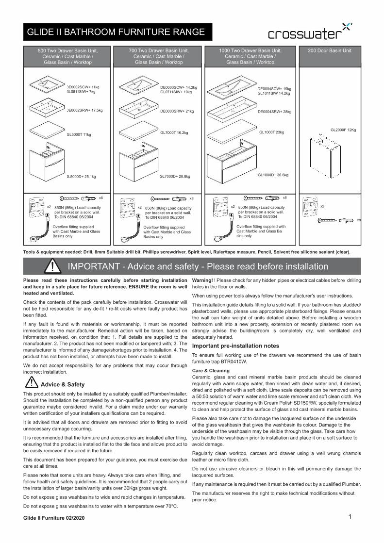
GLIDE II BATHROOM FURNITURE RANGE
IMPORTANT - Advice and safety - Please read before installation
Tools & equipment needed: Drill, 8mm Suitable drill bit, Phillips screwdriver, Spirit level, Ruler/tape measure, Pencil, Solvent free silicone sealant (clear).
Glide II Furniture 02/2020
Please read these instructions carefully before starting installation
and keep in a safe place for future reference. ENSURE the room is well
heated and ventilated.
Check the contents of the pack carefully before installation. Crosswater will
not be heid responsible for any de-fi t / re-fi t costs where faulty product has
been fi tted.
If any fault is found with materials or workmanship, it must be reported
immediately to the manufacturer. Remedial action will be taken, based on
information received, on condition that: 1. Full details are supplied to the
manufacturer. 2. The product has not been modifi ed or tampered with; 3. The
manufacturer is informed of any damage/shortages prior to installation. 4. The
product has not been installed, or attempts have been made to install.
We do not accept responsibility for any problems that may occur through
incorrect installation.
Advice & Safety
This product should only be installed by a suitably qualified Plumber/installer.
Should the installation be completed by a non-qualified person any product
guarantee maybe considered invalid. For a claim made under our warranty
written certification of your installers qualifications can be required.
It is advised that all doors and drawers are removed prior to fitting to avoid
unnecessary damage occurring.
It is recommended that the furniture and accessories are installed after tiling,
ensuring that the product is installed fl at to the tile face and allows product to
be easily removed if required in the future.
This document has been prepared for your guidance, you must exercise due
care at all times.
Please note that some units are heavy. Always take care when lifting, and
follow health and safety guidelines. It is recommended that 2 people carry out
the installation of larger basin/vanity units over 30Kgs gross weight.
Do not expose glass washbasins to wide and rapid changes in temperature.
Do not expose glass washbasins to water with a temperature over 70°C.
Warning! ! Please check for any hidden pipes or electrical cables before drilling
holes in the floor or walls.
When using power tools always follow the manufacturer’s user instructions.
This installation guide details fi tting to a solid wall. If your bathroom has studded/
plasterboard walls, please use appropriate plasterboard fi xings. Please ensure
the wall can take weight of units detailed above. Before installing a wooden
bathroom unit into a new property, extension or recently plastered room we
strongly advise the building/room is completely dry, well ventilated and
adequately heated.
Important pre-installation notes
To ensure full working use of the drawers we recommend the use of basin
furniture trap BTR0410W.
Care & Cleaning
Ceramic, glass and cast mineral marble basin products should be cleaned
regularly with warm soapy water, then rinsed with clean water and, if desired,
dried and polished with a soft cloth. Lime scale deposits can be removed using
a 50:50 solution of warm water and lime scale remover and soft clean cloth. We
recommend regular cleaning with Cream Polish SD150RW, specially formulated
to clean and help protect the surface of glass and cast mineral marble basins.
Please also take care not to damage the lacquered surface on the underside
of the glass washbasin that gives the washbasin its colour. Damage to the
underside of the washbasin may be visible through the glass. Take care how
you handle the washbasin prior to installation and place it on a soft surface to
avoid damage.
Regularly clean worktop, carcass and drawer using a well wrung chamois
leather or micro fi bre cloth.
Do not use abrasive cleaners or bleach in this will permanently damage the
lacquered surfaces.
If any maintenance is required then it must be carried out by a qualifi ed Plumber.
The manufacturer reserves the right to make technical modifi cations without
prior notice.
1
700 Two Drawer Basin Unit,
Ceramic / Cast Marble /
Glass Basin / Worktop
GL7000D+ 28.8kg
DE0003SCW+ 14.2kg
GL0711SIW+ 10kg
DE0003SRW+ 21kg
GL7000T 16.2kg
500 Two Drawer Basin Unit,
Ceramic / Cast Marble /
Glass Basin / Worktop
GL5000D+ 25.1kg
DE0002SCW+ 11kg
GL0511SIW+ 7kg
DE0002SRW+ 17.5kg
GL5000T 11kg
x8
1000 Two Drawer Basin Unit,
Ceramic / Cast Marble /
Glass Basin / Worktop
DE0004SCW+ 19kg
GL1011SIW 14.2kg
DE0004SRW+ 28kg
GL1000T 23kg
850N (86kg) Load capacity
per bracket on a solid wall.
To DIN 68840 06/2004
x2
Overfl ow fi tting supplied
with Cast Marble and Glass
Basins only
200 Door Basin Unit
GL1000D+ 36.6kg
x8
850N (86kg) Load capacity
per bracket on a solid wall.
To DIN 68840 06/2004
x2
Overfl ow fi tting supplied
with Cast Marble and Glass
Basins only
x8
850N (86kg) Load capacity
per bracket on a solid wall.
To DIN 68840 06/2004
x2
Overfl ow fi tting supplied with
Cast Marble and Glass Ba
sins only
x8
x2
GL2000F 12Kg
2
INSTALLATION INSTRUCTIONS
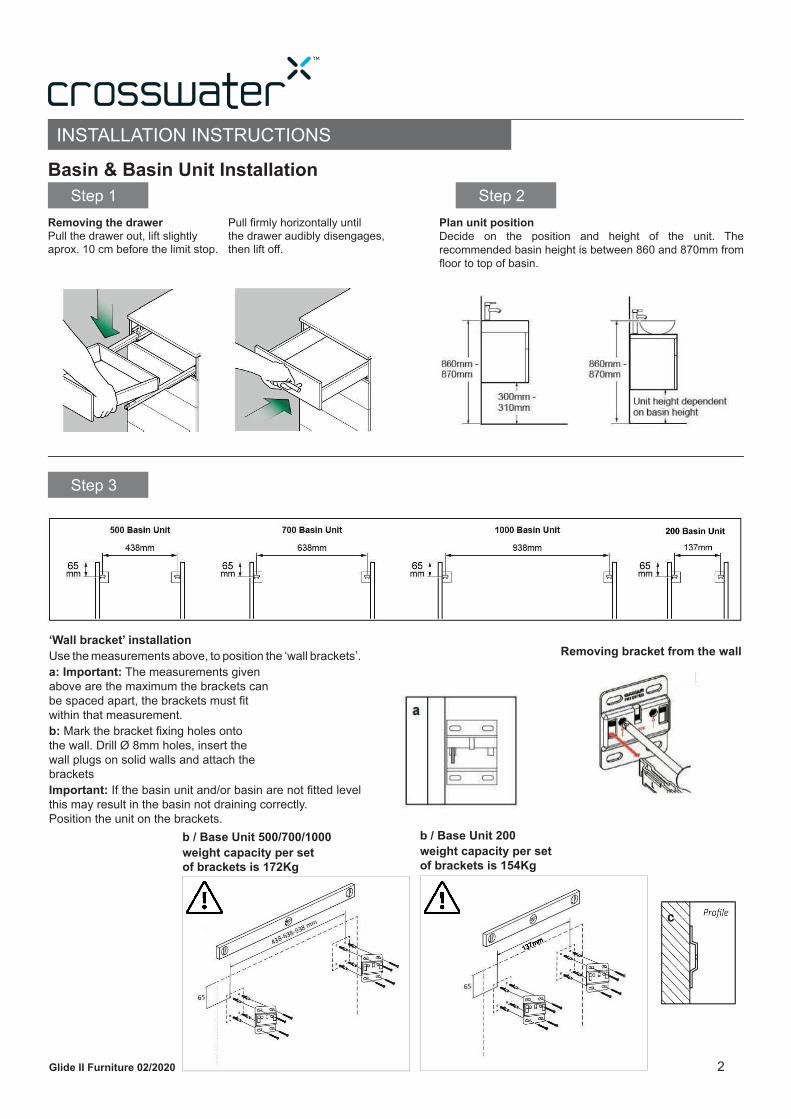
Basin & Basin Unit Installation
Step 1
Step 3
Step 2
Removing the drawer
Pull the drawer out, lift slightlyaprox. 10 cm before the limit stop.
‘Wall bracket’ installation
Use the measurements above, to position the ‘wall brackets’.
a: Important: The measurements given
above are the maximum the brackets can
be spaced apart, the brackets must fi t
within that measurement.
b: Mark the bracket fi xing holes onto
the wall. Drill Ø 8mm holes, insert the
wall plugs on solid walls and attach the
brackets
Important: If the basin unit and/or basin are not fi tted level
this may result in the basin not draining correctly.
Position the unit on the brackets.
Plan unit position
Decide on the position and height of the unit. The
recommended basin height is between 860 and 870mm from
fl oor to top of basin.
Pull fi rmly horizontally untilthe drawer audibly disengages,then lift off .
Removing bracket from the wall
a
Glide II Furniture 02/2020
b / Base Unit 500/700/1000 b / Base Unit 200
weight capacity per set
of brackets is 172Kg
weight capacity per set
of brackets is 154Kg
3
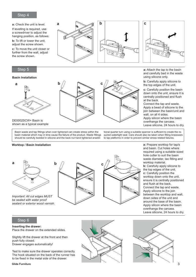
Step 4
Step 5
a: Check the unit is level.
If levelling is required, use
a screwdriver to adjust the
hanging position, as follows:
b: To lift or lower the unit,
adjust the screw shown.
c: To move the unit closer or
further from the wall, adjust
the screw shown.
Glide Furniture
Basin Installation
a: Attach the tap to the basin
and carefully bed in the waste
using silicone only.
b: Carefully apply silicone to
the top edges of the unit.
c: Carefully position the basin
down onto the unit, ensure it is
centrally positioned and fl ush
at the back.
Connect the tap and waste.
Apply a bead of silicone to the
join between the basin/unit and
wall, on all 4 sides.
Apply silicon where the basin
overthangs the carcass.
Leave silicone, 24 hours to dry.
DE0002SCW+ Basin is
shown as a typical example
Basin waste and tap fi ttings when over tightened can create stress within the
basin material which may in time cause the failure of the product. Waste fi ttings
should be carefully bedded in silicone and the back nut hand tightened anaddi-
tional quarter turn using a suitable spanner is suffi cient to create the re-
quired watertight seal. Care should also be taken when fi tting brassware
to tap platforms in order to prevent similar stress related failures.
a b c
a b c
Worktop / Basin Installation a: Prepare worktop for tap/s
and basin. Cut holes where
required using a suitable sized
hole cutter to suit the basin
waste diameter, tao fi tting and
worktop material.
b: Carefully apply silicone to
the top edges of the unit.
c: Carefully position the
worktop down onto the unit,
ensure it is centrally positioned
and fl ush at the back.
Connect the tap and waste.
Apply silicone to the join
between the worktop and wall,
down sides of the unit and
around the base of the basin.
Apply silicon where the basin
overthangs the carcass.
Leave silicone, 24 hours to dry.
Important: All cut edges MUST
be sealed with water proof
sealant or exterior wood varnish.
Step 6
Inserting the drawer:
Place the drawer on the extended slides.
Slightly lift the drawer at the front and then
push fully closed.
Drawer engages automatically!
Test to make sure the drawer operates correctly.
The hook situated on the back of the runner has
to be fi xed in the metal side of the drawer.
cba
4
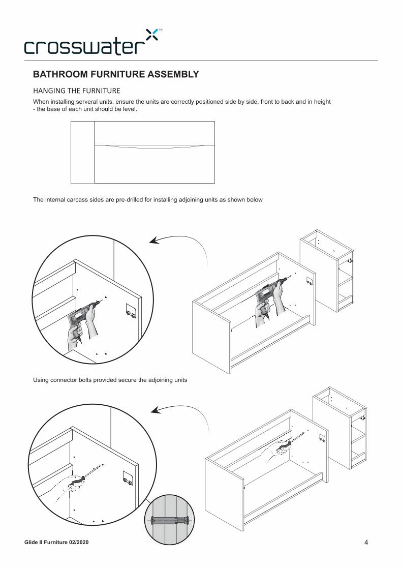
INBATHROOM FURNITURE ASSEMBLY
HANGING THE FURNITURE
When installing serveral units, ensure the units are correctly positioned side by side, front to back and in height
- the base of each unit should be level.
The internal carcass sides are pre-drilled for installing adjoining units as shown below
Using connector bolts provided secure the adjoining units
Glide II Furniture 02/2020
5
Step 1
Eccentric height adjustment on both sidesStep 3
Step 4
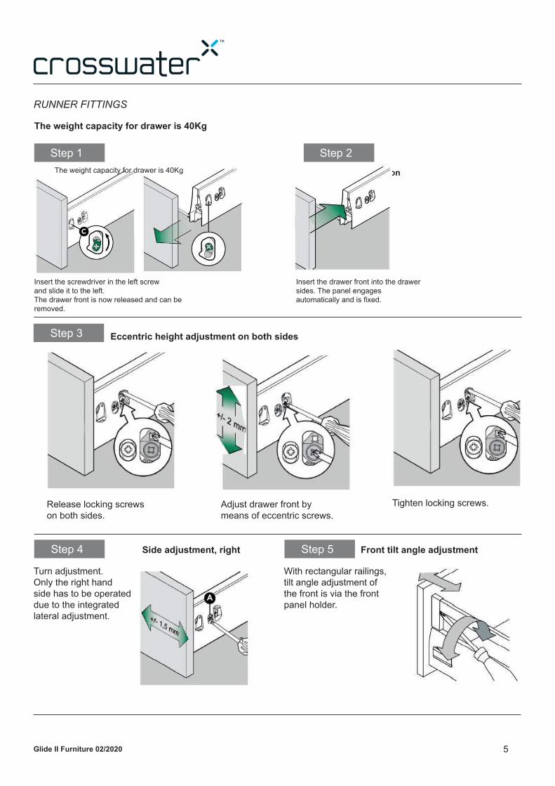
RUNNER FITTINGS
Step 2
Removing the drawer front Drawer front installation
Insert the screwdriver in the left screw
and slide it to the left.
The drawer front is now released and can be
removed.
Insert the drawer front into the drawer
sides. The panel engages
automatically and is fi xed.
Release locking screws
on both sides.
Adjust drawer front by
means of eccentric screws.
Tighten locking screws.
Side adjustment, right
Turn adjustment.
Only the right hand
side has to be operated
due to the integrated
lateral adjustment.
Step 5 Front tilt angle adjustment
With rectangular railings,
tilt angle adjustment of
the front is via the front
panel holder.
Glide II Furniture 02/2020
The weight capacity for drawer is 40Kg
The weight capacity for drawer is 40Kg
6
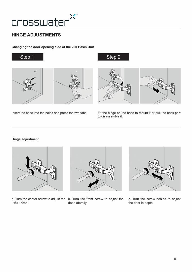
HINGE ADJUSTMENTS
Step 2
Insert the base into the holes and press the two tabs. Fit the hinge on the base to mount it or pull the back part to disassemble it.
a. Turn the center screw to adjust the height door.
b. Turn the front screw to adjust the
door laterally.
c. Turn the screw behind to adjust
the door in depth.
Hinge adjustment
Changing the door opening side of the 200 Basin Unit
Step 1
77
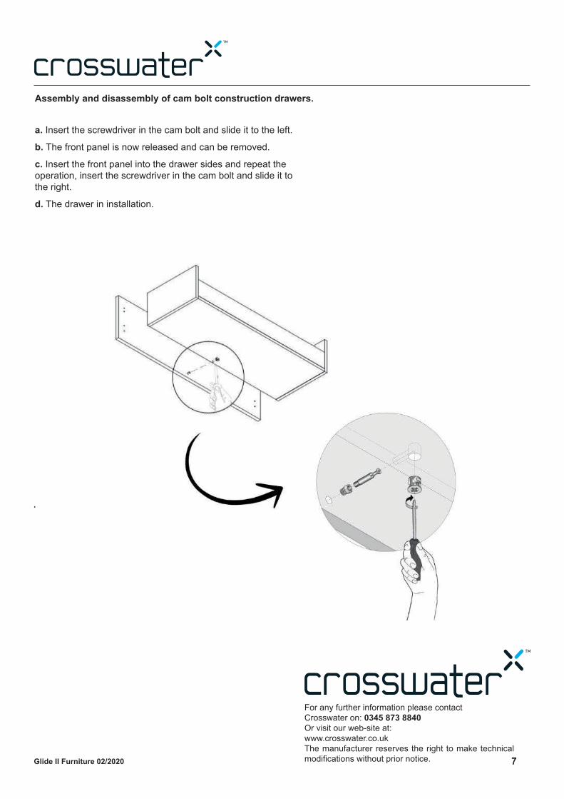
Assembly and disassembly of cam bolt construction drawers.
a. Insert the screwdriver in the cam bolt and slide it to the left.
b. The front panel is now released and can be removed.
c. Insert the front panel into the drawer sides and repeat the
operation, insert the screwdriver in the cam bolt and slide it to
the right.
d. The drawer in installation.
For any further information please contact
Crosswater on: 0345 873 8840
Or visit our web-site at:
www.crosswater.co.uk
The manufacturer reserves the right to make technical
modifi cations without prior notice.Glide II Furniture 02/2020