Embed Size (px)
Citation preview

GLENSOUND ELECTRONICS LTD GS-MPI004HD – UMTS(3G) & GSM Beltpack Unit And
GS-MPI005HD – UMTS(3G) & GSM Subrack Unit
DATE 16/12/11 ISSUE No. 1
HANDBOOK CONTENTS
DESCRIPTION PAGE No. PRODUCT WARRANTY: ........................................................................... 4 CE ................................................................................................................. 4 WASTE ELECTRICAL AND ELECTRONIC EQUIPMENT REGULATIONS 2006 (WEEE) ................................................................... 5 RoHS DIRECTIVE ....................................................................................... 5 FCC Regulations: .......................................................................................... 6
Antenna Placement .............................................................................6 Conformity Statement for: ............................................................................ 7
Quad-Band GSM/GPRS/EDGE and Tri-Band WCDMA/HSDPA MODULE ............................................................7
Panel Drawings & Block Diagram ................................................................ 8 GS-MPI004HD Front & Back ............................................................8 GS-MPI004HD Sides .........................................................................9 GS-MPI005HD Front & Back .......................................................... 10 Block Diagram ................................................................................. 11
GS-MPI007HD ........................................................................................... 12 Principle of Operation ................................................................................. 13
HD VOICE QUALITY CALLS ....................................................... 13 Power Supply ................................................................................... 13 Antenna ............................................................................................ 14 RF Signal Strength GS-MPI004HD & GS-MPI005HD ................... 14 RF Signal Strength GS-MPI007HD ................................................. 14 3G Signal Indication GS-MPI004HD & GS-MPI005HD ................ 14 3G Signal Indication GS-MPI007HD ............................................... 14 Audio Interface ................................................................................. 14 Audio Input Level Indication GS-MPI004HD & GS-MPI005HD ....................................................................................... 15 Audio Input/ OUTPUT Level Indication GS-MPI007HD ............... 15 Visual Interface GS-MPI004HD & GS-MPI005HD ........................ 15 Visual Interface GS-MPI007HD ...................................................... 16 Memory Slots ................................................................................... 16 SIM Card .......................................................................................... 16 PIN Code .......................................................................................... 16 Auto-Answer .................................................................................... 17 Sounder............................................................................................. 17

Audible Alert .................................................................................... 17 Operating Instructions ................................................................................. 18
Setup ................................................................................................. 18 Dialling ............................................................................................. 18 Enable / disable auto-answer ............................................................ 19 Store number in memory .................................................................. 19 Dial number from memory ............................................................... 19
GS-MPI004 HD Configuration options. ..................................................... 20 Troubleshooting .......................................................................................... 21 Wiring Information ..................................................................................... 23

G Glensound Electronics Ltd
Thank you for choosing a new Glensound product.
All rights reserved.
Information contained in this manual is subject to change without notice, if in doubt please contact us for the latest product information.
If you need any help with the product then we can be contacted at:
Glensound Electronics Ltd 1 – 6 Brooks Place
Maidstone Kent
ME14 1HE United Kingdom
Telephone: +44 (0) 1622 753662
Fax: +44 (0) 1622 762330
EMAIL ADDRESSES General enquires: [email protected]
Technical enquires: [email protected] Sales enquires: [email protected]

PRODUCT WARRANTY:
All equipment is fully tested before dispatch and carefully designed to provide you
with trouble free use for many years.
We have a policy of supporting products for as long as possible and guarantee to be able to support your product for a minimum of 10 years.
For a period of one year after the goods have been despatched the Company will guarantee the goods against any defect developing after proper use providing such
defects arise solely from faulty materials or workmanship and that the Customer shall return the goods to the Company’s works or their local dealer.
All non wear parts are guaranteed for 2 years after despatch and any defect
developing after proper use from faulty materials or workmanship will be repaired under this warranty providing the Customer returns the goods to the Company's
works or their local dealer.
CE
This equipment manufactured by Glensound Electronics Ltd of Brooks Place
Maidstone Kent ME14 1HE is CE marked and conforms to:
Low Voltage Directive: EN60204.1
Emissions: EN55103.1
Immunity: EN55103.2

WASTE ELECTRICAL AND ELECTRONIC EQUIPMENT REGULATIONS 2006 (WEEE)
Glensound Electronics Ltd is registered for business to business sales of WEEE in the UK our registration number is:
WEE/JJ0074UR
ROHS DIRECTIVE
EC directive 2002/95/EC restricts the use of the hazardous substances listed below in electrical and electronic equipment.
This product conforms to the above directive and for this purposes, the maximum concentration values of the restricted substances by weight in homogenous materials are:
Lead 0.1% Mercury 0.1%
Hexavalent Chromium 0.1% Polybrominated Biphenyls 0.1%
Polybrominated Diphenyl Ethers 0.1% Cadmium 0.01%

FCC REGULATIONS:
This device complies with part 15 of the FCC Rules. Operation is subject to the following two conditions: (1) This device may not cause harmful interference, and (2) this device must accept any interference received, including interference that may cause undesired operation. This device has been tested and found to comply with the limits for a Class B digital device, pursuant to Part 15 of the FCC Rules. These limits are designed to provide reasonable protection against harmful interference in a residential installation. This equipment generates, uses and can radiated radio frequency energy and, if not installed and used in accordance with the instructions, may cause harmful interference to radio communications. However, there is no guarantee that interference will not occur in a particular installation If this equipment does cause harmful interference to radio or television reception, which can be determined by turning the equipment off and on, the user is encouraged to try to correct the interference by one or more of the following measures: -Reorient or relocate the receiving antenna. -Increase the separation between the equipment and receiver. -Connect the equipment into an outlet on a circuit different from that to which the receiver is connected. -Consult the dealer or an experienced radio/TV technician for help. Changes or modifications not expressly approved by the party responsible for compliance could void the user‘s authority to operate the equipment.
ANTENNA PLACEMENT
The antenna(s) used for this transmitter must be installed to provide a separation distance of at least 20 cm from all persons, must not be collocated or operating in conjunction with any other antenna or transmitter, except in accordance with FCC multi-transmitter product procedures.
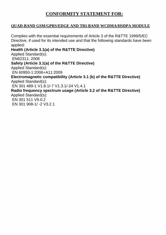
CONFORMITY STATEMENT FOR:
QUAD-BAND GSM/GPRS/EDGE AND TRI-BAND WCDMA/HSDPA MODULE
Complies with the essential requirements of Article 3 of the R&TTE 1999/5/EC Directive, if used for its intended use and that the following standards have been applied: Health (Article 3.1(a) of the R&TTE Directive) Applied Standard(s): EN62311: 2008 Safety (Article 3.1(a) of the R&TTE Directive) Applied Standard(s): EN 60950-1:2006+A11:2009 Electromagnetic compatibility (Article 3.1 (b) of t he R&TTE Directive) Applied Standard(s): EN 301 489-1 V1.8.1/-7 V1.3.1/-24 V1.4.1 Radio frequency spectrum usage (Article 3.2 of the R&TTE Directive) Applied Standard(s): EN 301 511 V9.0.2 EN 301 908-1/ -2 V3.2.1

PANEL DRAWINGS & BLOCK DIAGRAM
GS-MPI004HD FRONT & BACK

GS-MPI004HD SIDES

GS-MPI005HD FRONT & BACK
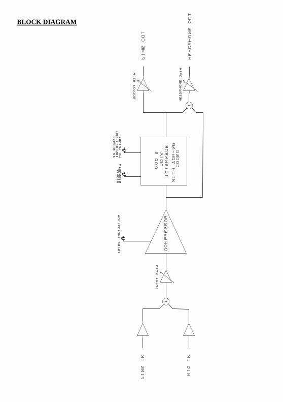
BLOCK DIAGRAM

GS-MPI007HD
G GS
-MP
I007
HD
U ww
w.g
lens
ound
.co.
ukS
ER
IAL
NO
:
PO
WE
R
12
3 64
5
97
8
#*
0
AB
CD
EF
GH
I
JKL
MN
OP
QR
ST
UV
WX
YZ
<>
EN
TE
R
ME
NU
DIA
LH
AN
G U
P
HP
VO
LU
ME
OU
TP
UT
INP
UT 7 6 5 4 3 2 1
7 6 5 4 3 2 1
12
3 64
5
97
8
#*
0
AB
CD
EF
GH
I
JKL
MN
OP
QR
ST
UV
WX
YZ
<>
EN
TE
R
ME
NU
DIA
LH
AN
G U
P
HP
VO
LUM
EO
UT
PU
TIN
PU
T 7 6 5 4 3 2 1
7 6 5 4 3 2 1
PO
WE
R
SIM
SIM
000
WC
E
88–264VAC
USB
USB CONTROL RS422 CONTROL
USB
USB CONTROL RS422 CONTROL
LINE
INLIN
E O
UT
AN
TE
NN
AA
NT
EN
NA
LINE
INLIN
E O
UT
+-
+-
+-
+-

PRINCIPLE OF OPERATION
The GS-MPI004HD is a portable (belt-pack) quad-band GSM and tri band UMTS mobile phone unit, with Mic and Line inputs, and a Line output. The GS-MPI005HD is a 1U sub-rack unit, designed for use in a 19" sub-rack, and contains three functionally separate GSM/UMTS mobile phone units, each equivalent to one GS-MPI004HD unit. The GS-MPI007HD is a 1U sub-rack and contains two functionally separate GSM/UMTS mobile phone units. All HD phones incorporate the AMR-WB codec and provide a 7kHz audio call when used on a network supporting AMR-WB (HD Voice).
HD VOICE QUALITY CALLS
HD Voice uses a codec called AMR-WB. This provides a 7kHz audio bandwidth across a mobile phone network. For HD Voice to work several things are required:
1) You are calling between 2 HD Voice enabled devices.
2) You are on a 3G (UMTS) circuit (HD voice does not work on GSM)
3) Your network operator supports HD Voice (see www.glensound.co.uk for latest list of Countries/ operators)
POWER SUPPLY The GS-MPI004HD can be powered from either an external DC supply (9 – 12V), or from 4 x AA batteries. The use of Lithium Manganese Dioxide batteries will yield longer talk times than standard Alkaline batteries. If both an external DC supply and batteries are connected, the external DC supply will take precedent. Note that the external DC supply cannot be used to charge the batteries.
A “LOW BATT” LED is fitted onto the front panel of the GS-MPI004HD. This LED will remain off while the battery voltage is above 1.1V per cell. Between 1.1V and 0.92V per cell, the LED will flash with increasing regularity, indicating an increased urgency to replace the battery. Below 0.92V per cell, the LED will remain on permanently, indicating that the unit is no longer operational due to low voltage.
The GS-MPI005HD and GS-MPI007HD, being sub-rack units, are powered by a 100 – 240V a.c. mains supply. The single mains supply is used to power all internal GSM mobile phones inside the unit. Neither the battery box nor the “LOW BATT” LED are fitted.

ANTENNA All units GS-MPI004HD, GS-MPI005HD and GS-MPI007HD use SMA Bulkhead female connectors, requiring an antenna with an SMA Bulkhead male connector. One antenna is required per GSM mobile phone unit. The GS-MPI004HD contains one mobile phone, and therefore requires one antenna. The GS-MPI005HD and GS-MPI007HD contain up to three mobile phone units, and therefore requires up to three antennae for full operation.
An optional N type connector can be specified prior to manufacture to replace the SMA on the GS-MPI005HD and GS-MPI007HD racks. The N type connector is larger and more robust than the more common SMA and is suitable for use when attaching to large heavy duty extension cables.
RF SIGNAL STRENGTH GS-MPI004HD & GS-MPI005HD A Tri-colour LED is positioned on the front panel to indicate RF signal strength Green: Full signal strength Yellow/Green: Average Yellow: Low signal Off: No signal
RF SIGNAL STRENGTH GS-MPI007HD
Signal strength is indicated by a series of bars on the LCD display. The more bars the stronger the signal present.
3G SIGNAL INDICATION GS-MPI004HD & GS-MPI005HD
The blue 3G LED indicates the presence of 3G. For HD Voice to work you must be on a 3G network that supports it. Therefore please note that the 3G signal indication alone does not guarantee the availability of HD Voice. For a current list of Countries and supporting networks that support HD voice please see www.glensound.co.uk
3G SIGNAL INDICATION GS-MPI007HD The presence of 3G is indicated by 3G being indicated on the LCD display. Please see above paragraph for further information.
AUDIO INTERFACE The GS-MPI004HD has separate balanced Mic and Line XLR inputs, which are selected by a toggle switch. Each mobile phone in the GS-MPI005HD has a Line input, but no Mic input. The input signal is adjusted by an input gain preset on the front panel, before being passed through a compressor to the UMTS/GSM

interface. Phantom power is not available on the Mic input of the GS-MPI004HD. Therefore, only dynamic microphones can be used.
The audio output from the UMTS/GSM interface is split between the Line output and the headphones output. The Line output is adjusted by an output gain preset on the front panel. The headphones output is mixed with a feed from the input (to provide sidetone) and adjusted by the “HP VOLUME” knob on the front panel, before being output on a ¼" Jack socket. On the GS-MPI004HD, this Jack socket is located on the right-hand side panel. On the GS-MPI005 mobile phones, it is located on the front panel. The headphones output is designed to drive high impedance headphones. Use of other types of headphones will significantly reduce battery life.
AUDIO INPUT LEVEL INDICATION GS-MPI004HD & GS-MPI005HD The red level LED indicates the input level to the GS-MPI004HD/005HD. Adjust the input control so the LED flickers on/off while speaking. Off: Level too low Flickering: Optimum level On: Level too high
AUDIO INPUT/ OUTPUT LEVEL INDICATION GS-MPI007HD
Indication of incoming/ outgoing audio levels is by small 7 LED PPM
VISUAL INTERFACE GS-MPI004HD & GS-MPI005HD Each mobile phone unit has a standard 4x3 keypad, a large green “DIAL” push-button and corresponding “OFF-HOOK” LED, and a large red “HANG-UP” push-button and corresponding “ON-HOOK” LED. The DIAL push-button is used to dial a phone number entered on the keypad, or to answer an incoming call. The HANG-UP push-button is used to end a call, reject an incoming call, or to clear a number that has been entered incorrectly.
When the unit is turned on, it will check if the PIN code is enabled. If it is, the phone will quickly flash the “SOUNDER” LED four times, every three seconds. This prompts the user to input the four digit PIN code in order to unlock the phone.
When the PIN code has been successfully entered, or if no PIN code was set on the SIM card, the red ON-HOOK LED will flash, indicating that the unit is attempting to register with a GSM network. Once registration is complete, the ON-HOOK LED will be on solid and the OFF-HOOK LED will be off. This is the phone's idle state, indicating that it is on-hook, and ready to dial or receive calls.
When a phone number is entered on the keypad and the DIAL push-button is pressed, the ON-HOOK LED will be turned off and the OFF-HOOK LED will start to flash, indicating that the phone is off-hook, and waiting for the phone at the other end to start ringing. When this happens, the sounder will play a slow ringing cadence, and the OFF-HOOK LED will flash in-time with the cadence. When the remote phone is picked up, the OFF-HOOK LED will be turned on solid, indicating that a call is in progress.

When an incoming call is received and the phone is on-hook, the ON-HOOK LED will remain on, the sounder will play a fast ringing cadence, and the OFF-HOOK LED will flash in-time with the cadence.
If a keypad button is pressed during a call, the phone will generate the corresponding DTMF tone.
VISUAL INTERFACE GS-MPI007HD The GS-MPI007HD has the added benefit of a large backlit LCD display. This display provides extra information to the operator than is available on the GS-MPI004 & 5HD units.
MEMORY SLOTS Each mobile phone unit has nine numbered memory slots, plus one redial memory slot. These are accessed using three yellow buttons: “REDIAL” , “RECALL” and “STORE”. These three buttons can only be used when the phone is on-hook. Pressing the REDIAL button will cause the phone to go off-hook and dial the last number dialled. To store a number in a memory slot, type the number on the keypad and press the STORE button, then press a button between 1 – 9 to select a memory slot. The OFF-HOOK LED will quickly flash twice, indicating that the number was successfully stored. To dial a number stored in memory, press the RECALL button, then press a button between 1 – 9 to select a memory slot. The phone will go off-hook and dial the number. If no valid phone number is stored in the selected memory slot, the sounder will give an indication of input error.
Note that the phone book stored on the SIM card is not accessible.
SIM CARD Each mobile phone unit requires a separate SIM card. The SIM card must be inserted upside down into the horizontal slot on the front panel, with the mitred corner facing forwards, and the gold-plated contacts facing upwards. The SIM card should be pressed in using a finger nail until it latches.. It can be removed by pressing with the finger nail until it unlatches.
Note that the phone book stored on the SIM card is not accessible.
PIN CODE When the mobile phone unit is turned on, it will check whether the PIN code on the SIM card is enabled or not, and will prompt the user accordingly (as described in the “Visual Interface” section, above. The mobile phone cannot be used to activate, deactivate, or change the SIM PIN. These actions should be performed by placing the SIM card in a standard mobile phone.

AUTO-ANSWER By default, the mobile phone will not attempt to automatically answer an incoming call. However, each mobile phone can be separately configured to automatically answer after 1 – 9 rings. To achieve this, hold down the appropriate keypad button (0 – 9) while powering on the unit. This will configure the phone to auto-answer at the beginning of the nth ring, where n is the number of the keypad button held down. If n is 0, auto-answering will be disabled. The auto-answer setting is stored, and recalled when the power is next turned on.
Note that many GSM networks activate a remote answering service after a fixed number of rings. The auto-answer setting is unable to affect this, however the GSM network provider may disable the remote answering service on request.
SOUNDER Each mobile phone unit has a simplistic sounder, which provides ringing cadences and indication of input error. The sounder can be toggled on and off using a push-button on the front of the panel. The on/off state of the sounder is stored, and recalled when the power is next turned on.
AUDIBLE ALERT
This produces an audible tone on the output audio/headphones to indicate in incoming call. This can be set to on or off.

OPERATING INSTRUCTIONS
SETUP To setup the GS-MPI004HD beltpack unit ready for use:
1. Screw suitable antenna onto SMA Bulkhead antenna connector.
2. Insert SIM card upside down into slot, following directions given in the previous chapter.
3. Place 4xAA batteries into battery holder, and / or connect external DC supply.
4. Turn unit on.
5. If sounder LED starts flashing, type in SIM PIN code.
6. Wait for red ON-HOOK LED to stop flashing, indicating that the GSM unit has successfully registered with the GSM network.
7. If using HD Voice then wait for the 3G light to illuminate.
(GS-MPI004HD unit is now ready for use)
To setup the GS-MPI005/7HD subrack unit ready for use:
1. Screw suitable antenna onto each SMA Bulkhead antenna connector, as required.
2. Insert each SIM card upside down into slot, as required, following directions given in the previous chapter.
3. Connect subrack unit to mains supply.
4. If any sounder LEDs start flashing, type in SIM PIN code.
5. Wait for all red ON-HOOK LEDs to stop flashing, indicating that each GSM unit has successfully registered with the GSM network.
6. If using HD Voice then wait for the 3G light to illuminate.
(GS-MPI005 unit is now ready for use)
DIALLING
1. Type in phone number on keypad. Press the red “HANG-UP” button and start again if the number was entered incorrectly.
2. Press the green “DIAL” button.
(ON-HOOK LED will turn off and OFF-HOOK LED will start to flash, indicating that the phone is off-hook, and waiting for the phone at the other end to start ringing)
(Phone will return to on-hook condition if call fails. Otherwise, when remote phone starts ringing, the sounder will play a slow ringing cadence, and the OFF-HOOK LED will flash in-time with the cadence)

(When remote phone is picked up, OFF-HOOK LED will turn on solid)
ENABLE / DISABLE AUTO-ANSWER 1. Turn off mobile phone unit.
2. Hold down numeric key corresponding to the ring number that auto-answering is desired on (0 for disable).
3. Turn on mobile phone unit, with numeric key still pressed.
4. Release key.
STORE NUMBER IN MEMORY 1. Type in phone number on keypad. Press the red “HANG-UP”
button and start again if the number was entered incorrectly.
2. Press the yellow “STORE” button.
3. Press a numeric key, between 1 – 9, indicating the memory slot desired.
(OFF-HOOK LED will quickly flash twice, indicating that the number was successfully stored)
DIAL NUMBER FROM MEMORY 1. Press the yellow “RECALL” button.
2. Press a numeric key, between 1 – 9, indicating the memory slot desired.
(The mobile phone will go off-hook and start dialling the phone number)

GS-MPI004 HD CONFIGURATION OPTIONS.
To enter the configuration menu, press and hold the STAR button, switch on the power and wait until the signal LED starts flashing. Key functions
0 Load factory defaults
1 Auto switching from 2G to 3G 3G LED will flash
2 2G only 3G LED OFF
3 3G only 3G LED ON
4 Echo canceller ON Off hook LED ON
5 Echo canceller OFF Off hook LED OFF
6 Noise suppressor ON On hook LED ON
7 Noise suppressor OFF On hook LED OFF
8 Peak compressor ON Batt LED ON
9 Peak compressor OFF Batt LED OFF
* Used to enter menu at power up
Store Toggle audible alert tone on/off Sounder LED
# Exit menu Device will reboot
When exiting the configuration menu, the phone will automatically reboot.

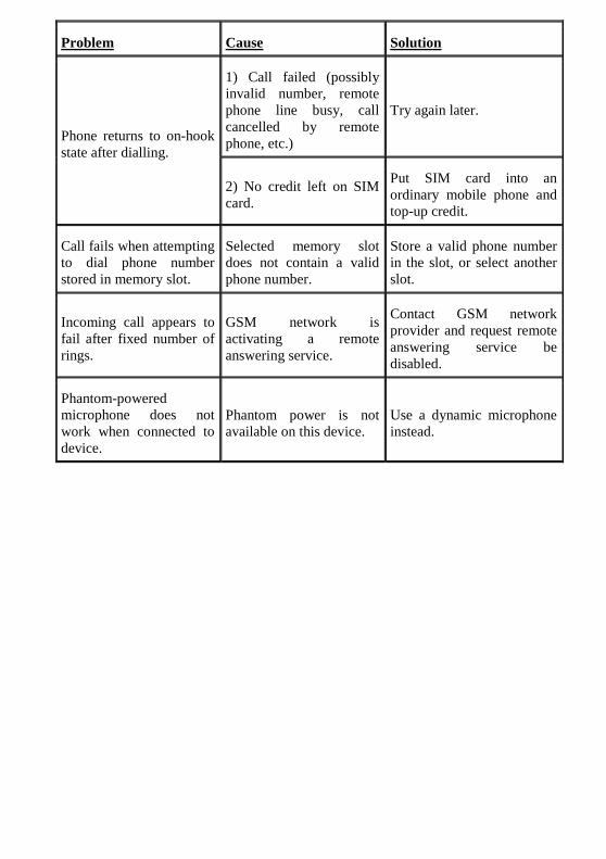
TROUBLESHOOTING
Problem Cause Solution
“BATT LOW” LED is flashing.
Battery voltage is low, but unit should continue to operate correctly for the moment. A shorter flash period denotes a flatter battery.
Consider changing batteries, or connect external DC supply.
“BATT LOW” LED is on solid.
Battery voltage is sufficiently low that the device will not operate correctly.
Change batteries, or connect external DC supply.
GSM unit fails to register with network (Red “ON-HOOK” LED and green “OFF-HOOK” LED are both off, “SOUNDER” LED is not flashing).
SIM card has not been inserted.
Insert SIM card, then turn unit off and on again.
“SOUNDER” LED starts flashing after power-on.
SIM PIN code is enabled on SIM card.
Type in 4-digit SIM PIN code.
GSM unit fails to register with network (Red “ON-HOOK” LED continues to flash for more than a few seconds at start-up), but “BATT LOW” LED is not on or flashing.
2) Signal strength is too low.
Move unit within range of a mobile phone mast.
3) Unsuitable GSM antenna is fitted.
Fit a suitable GSM antenna.
4) Momentary glitch on GSM network.
Turn unit off then on again.
Red “ON-HOOK” LED starts to flash after GSM registration is complete, or when phone goes off-hook
1) Battery voltage is sufficiently low that the device will not operate correctly, as indicated by state of “BATT LOW” LED.
Change batteries, or connect external DC supply.
2) Signal strength is too low.
Move unit within range of a mobile phone mast.
3) Unsuitable GSM antenna is fitted.
Fit a suitable GSM antenna.
Problem Cause Solution
Phone returns to on-hook state after dialling.
1) Call failed (possibly invalid number, remote phone line busy, call cancelled by remote phone, etc.)
Try again later.
2) No credit left on SIM card.
Put SIM card into an ordinary mobile phone and top-up credit.
Call fails when attempting to dial phone number stored in memory slot.
Selected memory slot does not contain a valid phone number.
Store a valid phone number in the slot, or select another slot.
Incoming call appears to fail after fixed number of rings.
GSM network is activating a remote answering service.
Contact GSM network provider and request remote answering service be disabled.
Phantom-powered microphone does not work when connected to device.
Phantom power is not available on this device.
Use a dynamic microphone instead.

WIRING INFORMATION
Type Function
3-pin XLR Socket/Plug MIC IN / LINE IN / LINE OUT Pin 1 = Ground Pin 2 = In Phase Pin 3 = Mate
6.35mm Jack Socket HEADPHONES Tip = In Phase Ring = Mate Sleeve = Ground
2.5mm DC Plug External DC Power In (9 – 12V) Centre = DC Positive Sleeve = DC Negative
SMA Bulkhead Socket ANTENNA Centre = RF Signal Sleeve = Chassis
Note:
The HEADPHONES output is designed to drive high impedance headphones. The use of other types of headphones will significantly reduce battery life.