Embed Size (px)
Citation preview
GLAST LAT Project Integration and Test CDR Peer Review, March 28, 2003
Document: LAT-PR-01779-01 Section 5 - Page 1
GLAST Large Area Telescope:GLAST Large Area Telescope:I & T Peer Review
I&T Test Plans
Brian GristSU-SLAC
Subsystem Engineer
Gamma-ray Large Gamma-ray Large Area Space Area Space TelescopeTelescope
GLAST LAT Project Integration and Test CDR Peer Review, March 28, 2003
Document: LAT-PR-01779-01 Section 5 - Page 2
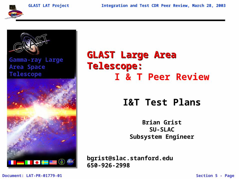
OutlineOutline
• Test flow• Plan Overview• Readiness Reviews• Test Plans (Sequence, Plan Flow, Requirements-From
Mechanical Systems, Facilities)– Comprehensive/Limited Performance
• Redundancy Verification– Survey– Mass Properties– Modal– EMI/EMC– Sine Vibration– Acoustic– TBAL/TVAC– Airplane Test (TBR)
GLAST LAT Project Integration and Test CDR Peer Review, March 28, 2003
Document: LAT-PR-01779-01 Section 5 - Page 3
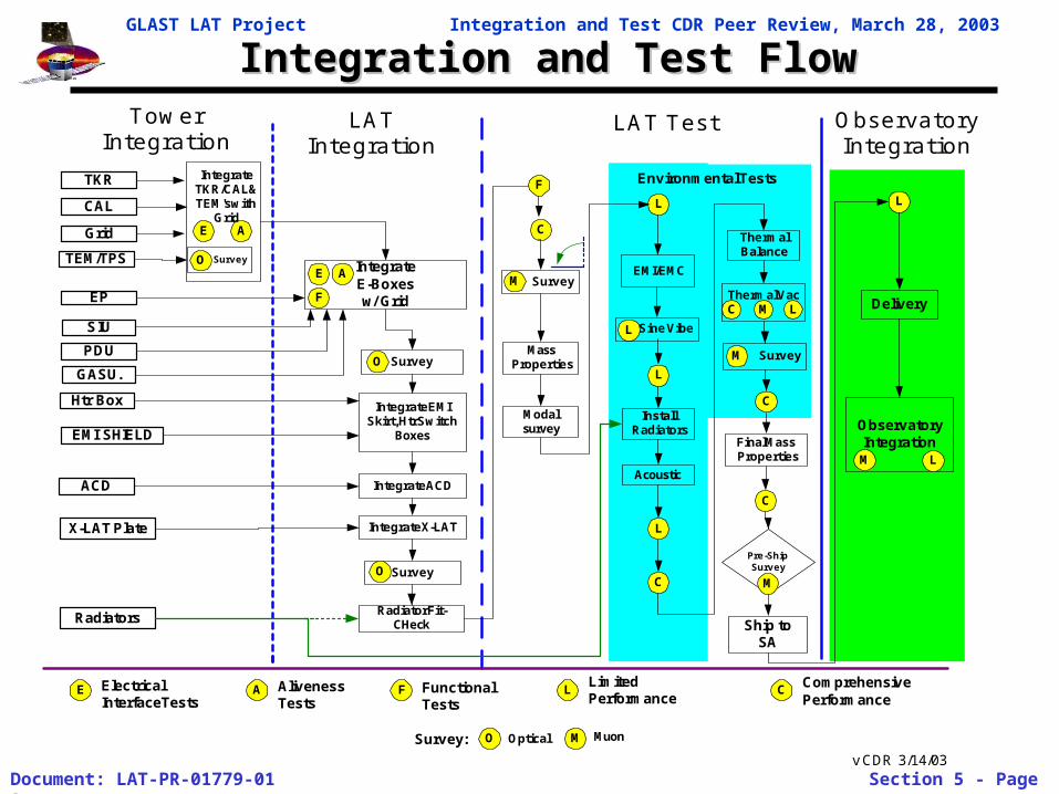
Integration and Test FlowIntegration and Test Flow
ObservatoryIntegration
Sine Vibe
TowerIntegration
LATIntegration
LAT Test ObservatoryIntegration
TKR
CAL
TEM/TPS
Grid
Radiators
EP
SIU
GASU.
PDU
ACD
IntegrateE-Boxesw/ Grid
Htr Box
Delivery
AlivenessTests
LimitedPerformance
X-LAT Plate
C
CLE A
A
MassProperties
EMI/EMC
L
InstallRadiators
Acoustic
L
C
Thermal Vac
ThermalBalance
C L
C
Final MassProperties
Pre-ShipSurvey
L
A
Ship toSA
F
F
F
EMI SHIELD
Survey Survey
M
O M
L
M
O Optical M Muon
IntegrateTKR/CAL &TEM's with
Grid
SurveyO
Integrate ACD
SurveyO
Integrate EMISkirt, Htr Switch
Boxes
Radiator Fit-CHeck
SurveyM
Modalsurvey
E
L
FunctionalTests
Survey:
L
ElectricalInterfaceTests
ComprehensivePerformance
Environmental Tests
E
M
C
v CDR 3/14/03
Integrate X-LAT
GLAST LAT Project Integration and Test CDR Peer Review, March 28, 2003
Document: LAT-PR-01779-01 Section 5 - Page 4
Test Plan DirectiveTest Plan Directive
GLAST LAT Project Integration and Test CDR Peer Review, March 28, 2003
Document: LAT-PR-01779-01 Section 5 - Page 5
ReviewsReviews
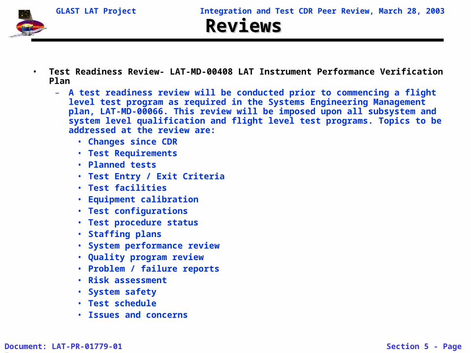
• Test Readiness Review- LAT-MD-00408 LAT Instrument Performance Verification Plan– A test readiness review will be conducted prior to commencing a flight level test
program as required in the Systems Engineering Management plan, LAT-MD-00066. This review will be imposed upon all subsystem and system level qualification and flight level test programs. Topics to be addressed at the review are:
• Changes since CDR• Test Requirements• Planned tests• Test Entry / Exit Criteria• Test facilities• Equipment calibration• Test configurations• Test procedure status• Staffing plans• System performance review• Quality program review• Problem / failure reports• Risk assessment• System safety• Test schedule• Issues and concerns
GLAST LAT Project Integration and Test CDR Peer Review, March 28, 2003
Document: LAT-PR-01779-01 Section 5 - Page 6
Comprehensive and Limited Performance TestsComprehensive and Limited Performance Tests
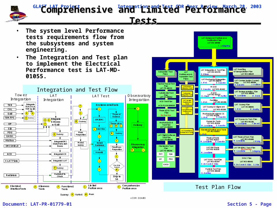
• The system level Performance tests requirements flow from the subsystems and system engineering.
• The Integration and Test plan to implement the Electrical Performance test is LAT-MD-01055.
ObservatoryIntegration
Sine Vibe
TowerIntegration
LATIntegration
LAT Test ObservatoryIntegration
TKR
CAL
TEM/TPS
Grid
Radiators
EP
SIU
GASU.
PDU
ACD
IntegrateE-Boxesw/ Grid
Htr Box
Delivery
AlivenessTests
LimitedPerformance
X-LAT Plate
C
CLE A
A
MassProperties
EMI/EMC
L
InstallRadiators
Acoustic
L
C
Thermal Vac
ThermalBalance
C L
C
Final MassProperties
Pre-ShipSurvey
L
A
Ship toSA
F
F
F
EMI SHIELD
Survey Survey
M
O M
L
M
O Optical M Muon
IntegrateTKR/CAL &TEM's with
Grid
SurveyO
Integrate ACD
SurveyO
Integrate EMISkirt, Htr Switch
Boxes
Radiator Fit-CHeck
SurveyM
Modalsurvey
E
L
FunctionalTests
Survey:
L
ElectricalInterfaceTests
ComprehensivePerformance
Environmental Tests
E
M
C
v CDR 3/14/03
Integrate X-LAT
Test Plan Flow
Integration and Test Flow
LATPerformance &Operation Test
Plans
Subsystem TestPlans
LAT Instrument PerformanceVerification Plan
LAT Integration & Test Plan
LAT Contamination ControlPlan
Electrical Performance Tests
Dynamics Tests
LAT SVAC Test Plan
E. Bloom
M-GSE
Facilities
Tracker Tower TestPlan
LAT-TD-00155
Calorimeter TestPlan
ACD Test Plan
Thermal S/S TestPlan
Mechanical S/STest Plan
LAT-SS-00493
TEM
GASU
SUI
EP PDU
LAT EMI TestsElectronics Test
Plan
LAT Instrumentation Plan
W. Davis
ComponentAliveness Tests
SubsystemIntegration Tests
LAT LimitedPerformance
Tests
LATComprehensive
PerformanceTests
LAT OperationalPerformance Tests
E. Gawehn
L. Wai
E. GawehnM. Lovellette
L. Wai
M. Lovellette
E. do Couto E Silva
M. Lovellette
J. CullinanE. Gawehn
Particle Test Plan
G. Godfrey
LAT-MD-01376
LAT-MD-01462
E-GSE
M. Huffer
LAT-MD-01386
LAT-MD-01055
LAT-MD-00452
LAT-MD-00404
LAT-MD-00890
LAT-SS-00262
LAT-TD-00296
LAT-MD-00408
ACD-PLAN-000050
LAT Flight SoftwareTest Plan
LAT-TD-00786
SVAC Plan
E. Do Couto E Silva
LAT-MD-01587
LAT EMI/EMC Test Plan
T. LeisgangM. Lovellette
LAT Thermal Test Plan
J. WangM. LovelletteLAT-MD-01600
Thermal Tests
M. Lovellette E. GawehnLAT-MD-01837
LAT Dynamics Test Plan
Y IsmaelM. LovelletteLAT-MD-01196
Mechanical Weight & CG
E. GawehnLAT-MD-01598
L. Wai
LAT Survey & Alignment
L. Wai LAT-MD-01586
LAT Survey Plan
M. NordbyL. WaiLAT-TD-00895
LAT Handling&Transportation Plan
T. Leisgang
LAT-MD-01838
LAT-MD-00440
No Number
LAT-MD-00649
LAT-MD-01836
No Number
LAT Mechanical Integration
L. Wai E. GawehnLAT-PS-00676
R. ClausLAT-MD-01533
LAT-MD-00446
S. Ritz
GLAST LAT Project Integration and Test CDR Peer Review, March 28, 2003
Document: LAT-PR-01779-01 Section 5 - Page 7
Comprehensive and Limited Performance TestsComprehensive and Limited Performance Tests
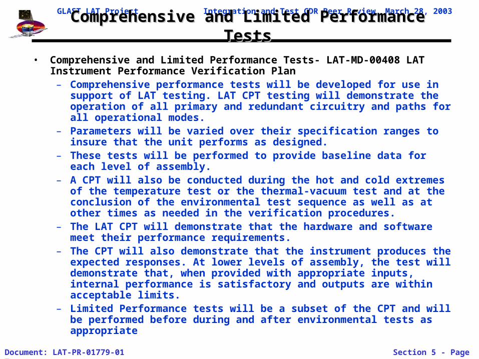
• Comprehensive and Limited Performance Tests- LAT-MD-00408 LAT Instrument Performance Verification Plan
– Comprehensive performance tests will be developed for use in support of LAT testing. LAT CPT testing will demonstrate the operation of all primary and redundant circuitry and paths for all operational modes.
– Parameters will be varied over their specification ranges to insure that the unit performs as designed.
– These tests will be performed to provide baseline data for each level of assembly.
– A CPT will also be conducted during the hot and cold extremes of the temperature test or the thermal-vacuum test and at the conclusion of the environmental test sequence as well as at other times as needed in the verification procedures.
– The LAT CPT will demonstrate that the hardware and software meet their performance requirements.
– The CPT will also demonstrate that the instrument produces the expected responses. At lower levels of assembly, the test will demonstrate that, when provided with appropriate inputs, internal performance is satisfactory and outputs are within acceptable limits.
– Limited Performance tests will be a subset of the CPT and will be performed before during and after environmental tests as appropriate
GLAST LAT Project Integration and Test CDR Peer Review, March 28, 2003
Document: LAT-PR-01779-01 Section 5 - Page 8
Comprehensive and Limited Performance TestsComprehensive and Limited Performance Tests
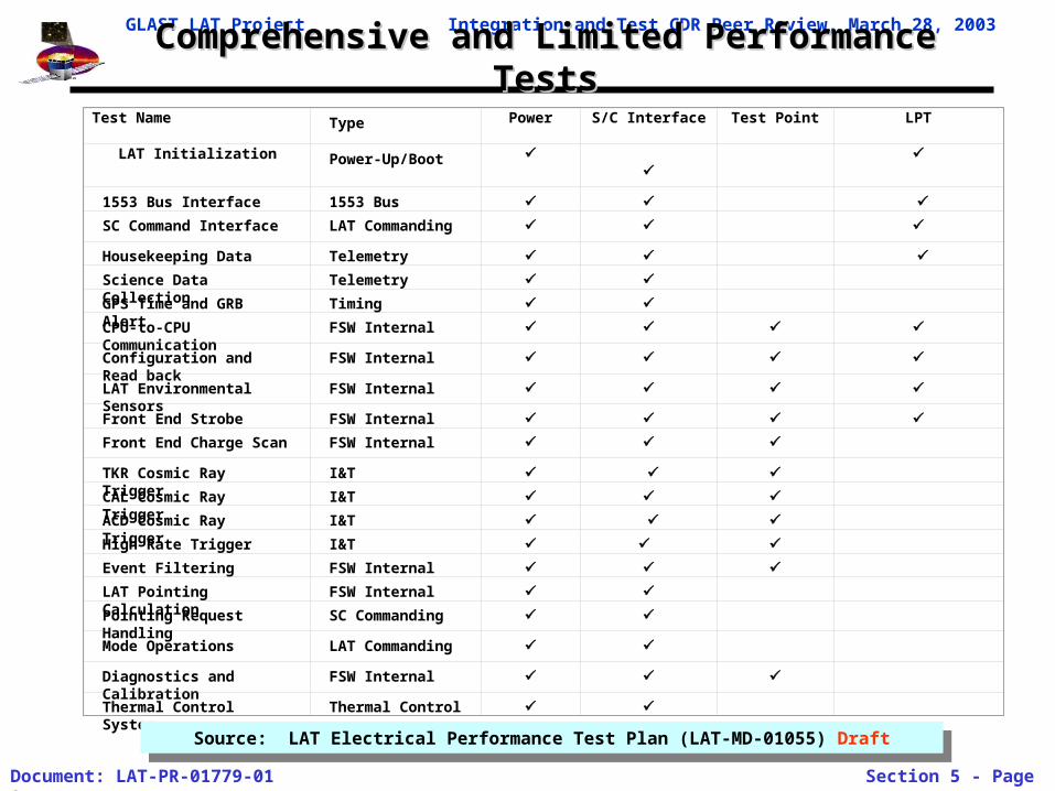
Test Name Type Power S/C Interface Test Point LPT
LAT Initialization Power-Up/Boot
1553 Bus Interface 1553 Bus
SC Command Interface LAT Commanding
Housekeeping Data Telemetry
Science Data Collection Telemetry
GPS Time and GRB Alert Timing
CPU-to-CPU Communication FSW Internal
Configuration and Read back FSW Internal
LAT Environmental Sensors FSW Internal
Front End Strobe FSW Internal
Front End Charge Scan FSW Internal
TKR Cosmic Ray Trigger I&T
CAL Cosmic Ray Trigger I&T
ACD Cosmic Ray Trigger I&T
High Rate Trigger I&T
Event Filtering FSW Internal
LAT Pointing Calculation FSW Internal
Pointing Request Handling SC Commanding
Mode Operations LAT Commanding
Diagnostics and Calibration FSW Internal
Thermal Control System Thermal Control
Source: LAT Electrical Performance Test Plan (LAT-MD-01055) DraftSource: LAT Electrical Performance Test Plan (LAT-MD-01055) Draft
GLAST LAT Project Integration and Test CDR Peer Review, March 28, 2003
Document: LAT-PR-01779-01 Section 5 - Page 9
Redundancy TestingRedundancy Testing
• A sequence of online “schema” (configurations) will be defined which mask out individual or combinations of Front Ends, Readout Controllers, Cable Controllers, TEMs.
• The tests will consist of looping through the schema and taking test data to validate the redundant electrical paths.
• LAT Electrical Performance Test Plan (LAT-MD-01055) details the redundant path testing.
GLAST LAT Project Integration and Test CDR Peer Review, March 28, 2003
Document: LAT-PR-01779-01 Section 5 - Page 10
Survey PlanSurvey Plan
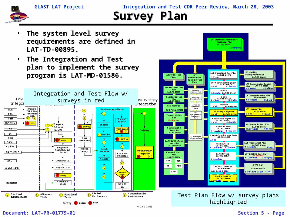
• The system level survey requirements are defined in LAT-TD-00895.
• The Integration and Test plan to implement the survey program is LAT-MD-01586.
ObservatoryIntegration
Sine Vibe
TowerIntegration
LATIntegration
LAT Test ObservatoryIntegration
TKR
CAL
TEM/TPS
Grid
Radiators
EP
SIU
GASU.
PDU
ACD
IntegrateE-Boxesw/ Grid
Htr Box
Delivery
AlivenessTests
LimitedPerformance
X-LAT Plate
C
CLE A
A
MassProperties
EMI/EMC
L
InstallRadiators
Acoustic
L
C
Thermal Vac
ThermalBalance
C L
C
Final MassProperties
Pre-ShipSurvey
L
A
Ship toSA
F
F
F
EMI SHIELD
Survey Survey
M
O M
L
M
O Optical M Muon
IntegrateTKR/CAL &TEM's with
Grid
SurveyO
Integrate ACD
SurveyO
Integrate EMISkirt, Htr Switch
Boxes
Radiator Fit-CHeck
SurveyM
Modalsurvey
E
L
FunctionalTests
Survey:
L
ElectricalInterfaceTests
ComprehensivePerformance
Environmental Tests
E
M
C
v CDR 3/14/03
Integrate X-LAT
Test Plan Flow w/ survey plans highlighted
Integration and Test Flow w/ surveys in red
LATPerformance &Operation Test
Plans
Subsystem TestPlans
LAT Instrument PerformanceVerification Plan
LAT Integration & Test Plan
LAT Contamination ControlPlan
Electrical Performance Tests
Dynamics Tests
LAT SVAC Test Plan
E. Bloom
M-GSE
Facilities
Tracker Tower TestPlan
LAT-TD-00155
Calorimeter TestPlan
ACD Test Plan
Thermal S/S TestPlan
Mechanical S/STest Plan
LAT-SS-00493
TEM
GASU
SUI
EP PDU
LAT EMI TestsElectronics Test
Plan
LAT Instrumentation Plan
W. Davis
ComponentAliveness Tests
SubsystemIntegration Tests
LAT LimitedPerformance
Tests
LATComprehensive
PerformanceTests
LAT OperationalPerformance Tests
E. Gawehn
L. Wai
E. GawehnM. Lovellette
L. Wai
M. Lovellette
E. do Couto E Silva
M. Lovellette
J. CullinanE. Gawehn
Particle Test Plan
G. Godfrey
LAT-MD-01376
LAT-MD-01462
E-GSE
M. Huffer
LAT-MD-01386
LAT-MD-01055
LAT-MD-00452
LAT-MD-00404
LAT-MD-00890
LAT-SS-00262
LAT-TD-00296
LAT-MD-00408
ACD-PLAN-000050
LAT Flight SoftwareTest Plan
LAT-TD-00786
SVAC Plan
E. Do Couto E Silva
LAT-MD-01587
LAT EMI/EMC Test Plan
T. LeisgangM. Lovellette
LAT Thermal Test Plan
J. WangM. LovelletteLAT-MD-01600
Thermal Tests
M. Lovellette E. GawehnLAT-MD-01837
LAT Dynamics Test Plan
Y IsmaelM. LovelletteLAT-MD-01196
Mechanical Weight & CG
E. GawehnLAT-MD-01598
L. Wai
LAT Survey & Alignment
L. Wai LAT-MD-01586
LAT Survey Plan
M. NordbyL. WaiLAT-TD-00895
LAT Handling&Transportation Plan
T. Leisgang
LAT-MD-01838
LAT-MD-00440
No Number
LAT-MD-00649
LAT-MD-01836
No Number
LAT Mechanical Integration
L. Wai E. GawehnLAT-PS-00676
R. ClausLAT-MD-01533
LAT-MD-00446
S. Ritz
GLAST LAT Project Integration and Test CDR Peer Review, March 28, 2003
Document: LAT-PR-01779-01 Section 5 - Page 11
Survey Test OrganizationSurvey Test Organization
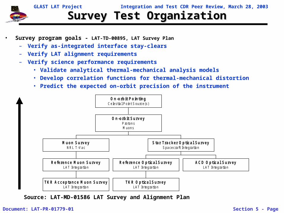
• Survey program goals - LAT-TD-00895, LAT Survey Plan
– Verify as-integrated interface stay-clears
– Verify LAT alignment requirements
– Verify science performance requirements
• Validate analytical thermal-mechanical analysis models
• Develop correlation functions for thermal-mechanical distortion
• Predict the expected on-orbit precision of the instrument
Source: LAT-MD-01586 LAT Survey and Alignment Plan
TKR Acceptance Muon SurveyLAT Integratio n
Reference Muon SurveyLAT Integratio n
Muon SurveyNRL T -Va c
TKR Optical SurveyLAT Integratio n
Reference Optical SurveyLAT Integratio n
ACD Optical SurveyLAT Integratio n
Star Tracker Optical SurveySpacecraft Integratio n
On-orbit SurveyProton sM uon s
On-orbit PointingCelestia l Point S ource(s )
GLAST LAT Project Integration and Test CDR Peer Review, March 28, 2003
Document: LAT-PR-01779-01 Section 5 - Page 12
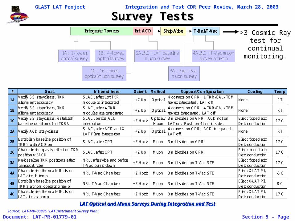
Survey TestsSurvey Tests
1A: 1-Toweroptical survey
Integrate Towers Int. ACD Ship/Vibe T-Bal/T-Vac
1B: 4-Toweroptical survey
2A,B,C: LAT baselinemuon survey
1C: 16-Toweroptical/muon survey
3A: Pre-T-Vacmuon survey
4A,B,C: T-Vac muonsurvey at temp
# Goal When/Where Orient. Method Support/Configuration Cooling Temp
1AVerify SS stayclears, TKR alignment accuracy
SLAC, after 1st TKR module is integrated
+Z Up Optical4 corners on GPR; 1 TKR/CAL/ TEM tower integrated. LAT off
None RT
1BVerify SS stayclears, TKR alignment accuracy
SLAC, after 4 TKR modules are integrated
+Z Up Optical4 corners on GPR; 4 TKR/CAL/ TEM towers integrated. LAT off
None RT
1CVerify SS stayclears; establish baseline position of all TKR's
SLAC, before ACD integration
+Z HorizOptical/
Muon3 mid-sides on GPR; ACD not on LAT on. Push on 4th mid-side.
Elec: forced air; Det: conduction
17 C
2A Verify ACD stay-clearsSLAC, after ACD and X-LAT Plate integration
+Z Up Optical4-corners on GPR; ACD integrated. LAT off.
None RT
2BEstablish baseline position of TKR's with ACD on
SLAC, after CPT +Z Horiz Muon 3 mid-sides on GPRElec: forced air; Det: conduction
17 C
2CCharacterize gravity effect on TKR position w/ ACD
SLAC, after CPT +Z Up Muon 3 mid-sides on GPRElec: forced air; Det: conduction
17 C
3ARe-baseline TKR positions after transport, vibe
NRL, after vibe and before T-Vac pump-down
+Z Horiz Muon 3 mid-sides on T-Vac STEElec: forced air; Det: conduction
17 C
4ACharacterize thermal effects on LAT at min temp
NRL T-Vac Chamber +Z Horiz Muon 3 mid-sides on T-Vac STEElec: X-LAT Pl, Det: conduction
-5 C
4BEstablish baseline position of TKR's at nom operating temp
NRL T-Vac Chamber +Z Horiz Muon 3 mid-sides on T-Vac STEElec: X-LAT Pl, Det: conduction
8 C
4CCharacterize thermal effects on LAT at max temp
NRL T-Vac Chamber +Z Horiz Muon 3 mid-sides on T-Vac STEElec: X-LAT Pl, Det: conduction
17 C
LAT Optical and Muon Surveys During Integration and TestLAT Optical and Muon Surveys During Integration and Test
Source: LAT-MD-00895 “LAT Instrument Survey Plan”
>3 Cosmic Ray test for continual
monitoring.
GLAST LAT Project Integration and Test CDR Peer Review, March 28, 2003
Document: LAT-PR-01779-01 Section 5 - Page 13
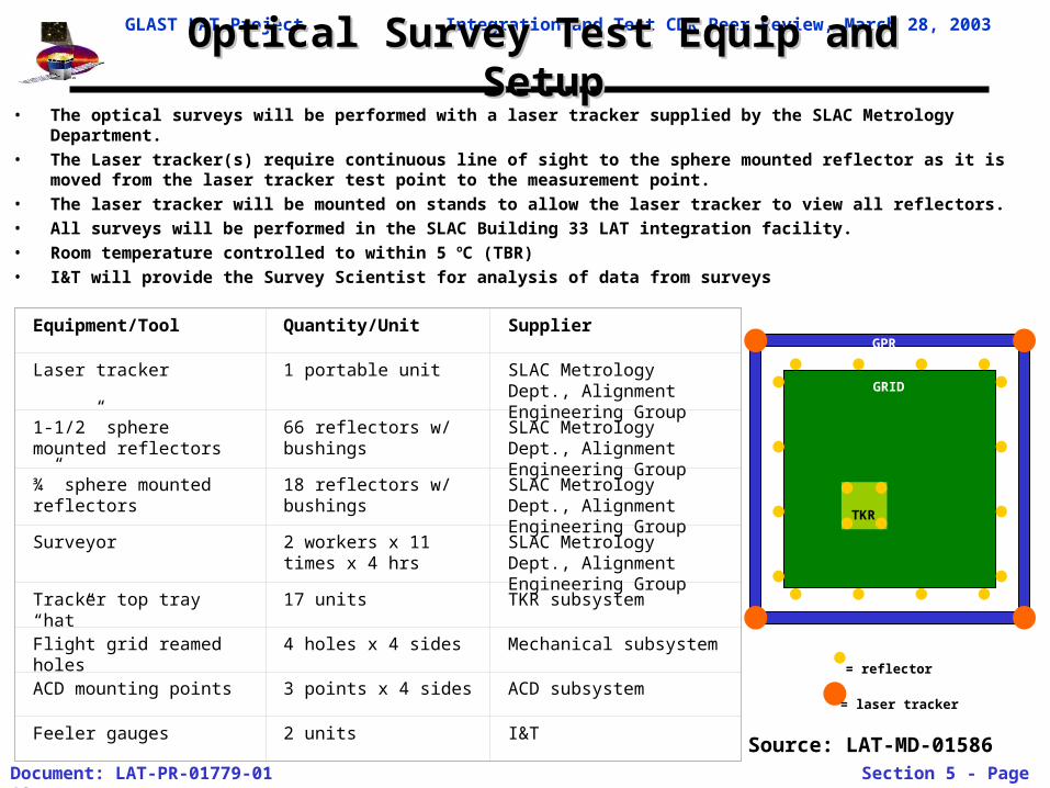
Optical Survey Test Equip and SetupOptical Survey Test Equip and Setup• The optical surveys will be performed with a laser tracker supplied by the SLAC Metrology Department.• The Laser tracker(s) require continuous line of sight to the sphere mounted reflector as it is moved from the laser
tracker test point to the measurement point. • The laser tracker will be mounted on stands to allow the laser tracker to view all reflectors. • All surveys will be performed in the SLAC Building 33 LAT integration facility.• Room temperature controlled to within 5 oC (TBR)• I&T will provide the Survey Scientist for analysis of data from surveys
Equipment/Tool Quantity/Unit Supplier
Laser tracker 1 portable unit SLAC Metrology Dept., Alignment Engineering Group
1-1/2” sphere mounted reflectors
66 reflectors w/ bushings SLAC Metrology Dept., Alignment Engineering Group
¾” sphere mounted reflectors 18 reflectors w/ bushings SLAC Metrology Dept., Alignment Engineering Group
Surveyor 2 workers x 11 times x 4 hrs
SLAC Metrology Dept., Alignment Engineering Group
Tracker top tray “hat” 17 units TKR subsystem
Flight grid reamed holes 4 holes x 4 sides Mechanical subsystem
ACD mounting points 3 points x 4 sides ACD subsystem
Feeler gauges 2 units I&T
= reflector
= laser tracker
GRID
TKR
GPR
Source: LAT-MD-01586
GLAST LAT Project Integration and Test CDR Peer Review, March 28, 2003
Document: LAT-PR-01779-01 Section 5 - Page 14
Mass PropertiesMass Properties
ObservatoryIntegration
Sine Vibe
TowerIntegration
LATIntegration
LAT Test ObservatoryIntegration
TKR
CAL
TEM/TPS
Grid
Radiators
EP
SIU
GASU.
PDU
ACD
IntegrateE-Boxesw/ Grid
Htr Box
Delivery
AlivenessTests
LimitedPerformance
X-LAT Plate
C
CLE A
A
MassProperties
EMI/EMC
L
InstallRadiators
Acoustic
L
C
Thermal Vac
ThermalBalance
C L
C
Final MassProperties
Pre-ShipSurvey
L
A
Ship toSA
F
F
F
EMI SHIELD
Survey Survey
M
O M
L
M
O Optical M Muon
IntegrateTKR/CAL &TEM's with
Grid
SurveyO
Integrate ACD
SurveyO
Integrate EMISkirt, Htr Switch
Boxes
Radiator Fit-CHeck
SurveyM
Modalsurvey
E
L
FunctionalTests
Survey:
L
ElectricalInterfaceTests
ComprehensivePerformance
Environmental Tests
E
M
C
v CDR 3/14/03
Integrate X-LAT
Test Plan Flow
Integration and Test Flow
LATPerformance &Operation Test
Plans
Subsystem TestPlans
LAT Instrument PerformanceVerification Plan
LAT Integration & Test Plan
LAT Contamination ControlPlan
Electrical Performance Tests
Dynamics Tests
LAT SVAC Test Plan
E. Bloom
M-GSE
Facilities
Tracker Tower TestPlan
LAT-TD-00155
Calorimeter TestPlan
ACD Test Plan
Thermal S/S TestPlan
Mechanical S/STest Plan
LAT-SS-00493
TEM
GASU
SUI
EP PDU
LAT EMI TestsElectronics Test
Plan
LAT Instrumentation Plan
W. Davis
ComponentAliveness Tests
SubsystemIntegration Tests
LAT LimitedPerformance
Tests
LATComprehensive
PerformanceTests
LAT OperationalPerformance Tests
E. Gawehn
L. Wai
E. GawehnM. Lovellette
L. Wai
M. Lovellette
E. do Couto E Silva
M. Lovellette
J. CullinanE. Gawehn
Particle Test Plan
G. Godfrey
LAT-MD-01376
LAT-MD-01462
E-GSE
M. Huffer
LAT-MD-01386
LAT-MD-01055
LAT-MD-00452
LAT-MD-00404
LAT-MD-00890
LAT-SS-00262
LAT-TD-00296
LAT-MD-00408
ACD-PLAN-000050
LAT Flight SoftwareTest Plan
LAT-TD-00786
SVAC Plan
E. Do Couto E Silva
LAT-MD-01587
LAT EMI/EMC Test Plan
T. LeisgangM. Lovellette
LAT Thermal Test Plan
J. WangM. LovelletteLAT-MD-01600
Thermal Tests
M. Lovellette E. GawehnLAT-MD-01837
LAT Dynamics Test Plan
Y IsmaelM. LovelletteLAT-MD-01196
Mechanical Weight & CG
E. GawehnLAT-MD-01598
L. Wai
LAT Survey & Alignment
L. Wai LAT-MD-01586
LAT Survey Plan
M. NordbyL. WaiLAT-TD-00895
LAT Handling&Transportation Plan
T. Leisgang
LAT-MD-01838
LAT-MD-00440
No Number
LAT-MD-00649
LAT-MD-01836
No Number
LAT Mechanical Integration
L. Wai E. GawehnLAT-PS-00676
R. ClausLAT-MD-01533
LAT-MD-00446
S. Ritz
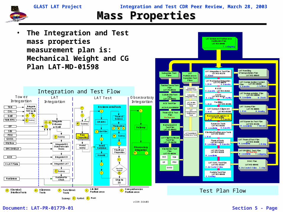
• The Integration and Test mass properties measurement plan is: Mechanical Weight and CG Plan LAT-MD-01598
GLAST LAT Project Integration and Test CDR Peer Review, March 28, 2003
Document: LAT-PR-01779-01 Section 5 - Page 15
Mass PropertiesMass Properties
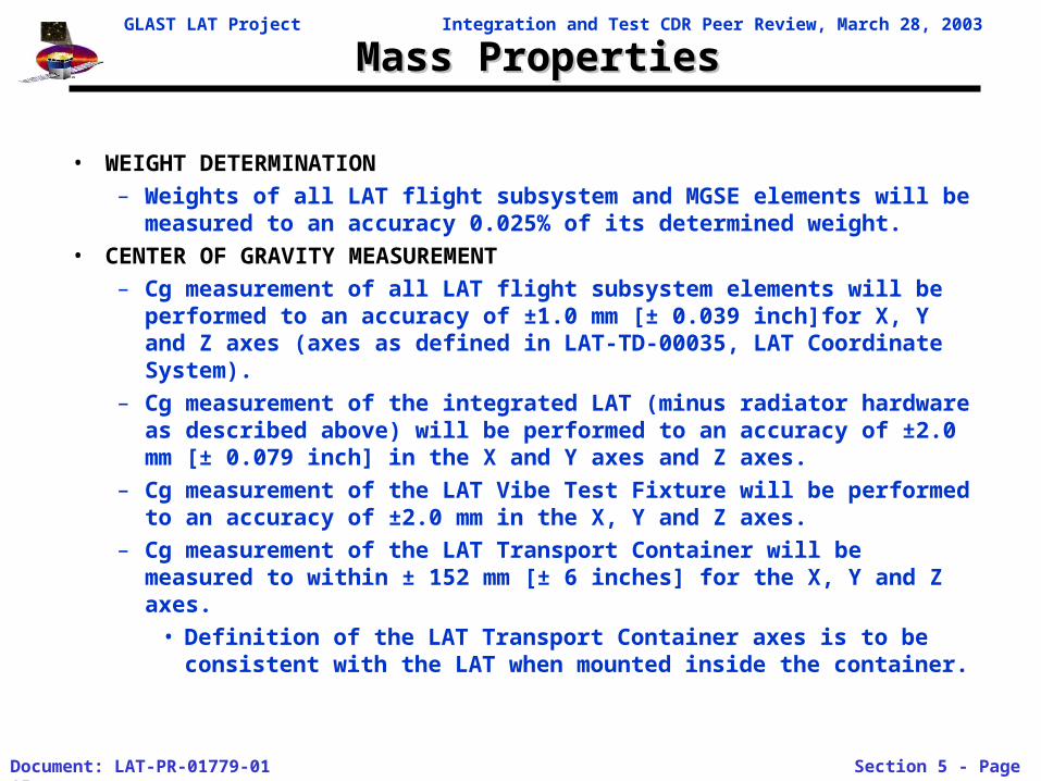
• WEIGHT DETERMINATION
– Weights of all LAT flight subsystem and MGSE elements will be measured to an accuracy 0.025% of its determined weight.
• CENTER OF GRAVITY MEASUREMENT
– Cg measurement of all LAT flight subsystem elements will be performed to an accuracy of ±1.0 mm [± 0.039 inch]for X, Y and Z axes (axes as defined in LAT-TD-00035, LAT Coordinate System).
– Cg measurement of the integrated LAT (minus radiator hardware as described above) will be performed to an accuracy of ±2.0 mm [± 0.079 inch] in the X and Y axes and Z axes.
– Cg measurement of the LAT Vibe Test Fixture will be performed to an accuracy of ±2.0 mm in the X, Y and Z axes.
– Cg measurement of the LAT Transport Container will be measured to within ± 152 mm [± 6 inches] for the X, Y and Z axes.
• Definition of the LAT Transport Container axes is to be consistent with the LAT when mounted inside the container.
GLAST LAT Project Integration and Test CDR Peer Review, March 28, 2003
Document: LAT-PR-01779-01 Section 5 - Page 16
Modal SurveyModal Survey
Modalsurvey Observatory
Integration
Sine Vibe
TowerIntegration
LATIntegration
LAT Test ObservatoryIntegration
TKR
CAL
TEM/TPS
Grid
Radiators
EP
SIU
GASU.
PDU
ACD
IntegrateE-Boxesw/ Grid
Htr Box
Delivery
AlivenessTests
LimitedPerformance
X-LAT Plate
C
CLE A
A
MassProperties
EMI/EMC
L
InstallRadiators
Acoustic
L
C
Thermal Vac
ThermalBalance
C L
C
Final MassProperties
Pre-ShipSurvey
L
A
Ship toSA
F
F
F
EMI SHIELD
Survey Survey
M
O M
L
M
O Optical M Muon
IntegrateTKR/CAL &TEM's with
Grid
SurveyO
Integrate ACD
SurveyO
Integrate EMISkirt, Htr Switch
Boxes
Radiator Fit-CHeck
SurveyME
L
FunctionalTests
Survey:
L
ElectricalInterfaceTests
ComprehensivePerformance
Environmental Tests
E
M
C
v CDR 3/14/03
Integrate X-LAT
Test Plan Flow
Integration and Test Flow
LATPerformance &Operation Test
Plans
Subsystem TestPlans
LAT Instrument PerformanceVerification Plan
LAT Integration & Test Plan
LAT Contamination ControlPlan
Electrical Performance Tests
Dynamics Tests
LAT SVAC Test Plan
E. Bloom
M-GSE
Facilities
Tracker Tower TestPlan
LAT-TD-00155
Calorimeter TestPlan
ACD Test Plan
Thermal S/S TestPlan
Mechanical S/STest Plan
LAT-SS-00493
TEM
GASU
SUI
EP PDU
LAT EMI TestsElectronics Test
Plan
LAT Instrumentation Plan
W. Davis
ComponentAliveness Tests
SubsystemIntegration Tests
LAT LimitedPerformance
Tests
LATComprehensive
PerformanceTests
LAT OperationalPerformance Tests
E. Gawehn
L. Wai
E. GawehnM. Lovellette
L. Wai
M. Lovellette
E. do Couto E Silva
M. Lovellette
J. CullinanE. Gawehn
Particle Test Plan
G. Godfrey
LAT-MD-01376
LAT-MD-01462
E-GSE
M. Huffer
LAT-MD-01386
LAT-MD-01055
LAT-MD-00452
LAT-MD-00404
LAT-MD-00890
LAT-SS-00262
LAT-TD-00296
LAT-MD-00408
ACD-PLAN-000050
LAT Flight SoftwareTest Plan
LAT-TD-00786
SVAC Plan
E. Do Couto E Silva
LAT-MD-01587
LAT EMI/EMC Test Plan
T. LeisgangM. Lovellette
LAT Thermal Test Plan
J. WangM. LovelletteLAT-MD-01600
Thermal Tests
M. Lovellette E. GawehnLAT-MD-01837
LAT Dynamics Test Plan
Y IsmaelM. LovelletteLAT-MD-01196
Mechanical Weight & CG
E. GawehnLAT-MD-01598
L. Wai
LAT Survey & Alignment
L. Wai LAT-MD-01586
LAT Survey Plan
M. NordbyL. WaiLAT-TD-00895
LAT Handling&Transportation Plan
T. Leisgang
LAT-MD-01838
LAT-MD-00440
No Number
LAT-MD-00649
LAT-MD-01836
No Number
LAT Mechanical Integration
L. Wai E. GawehnLAT-PS-00676
R. ClausLAT-MD-01533
LAT-MD-00446
S. Ritz
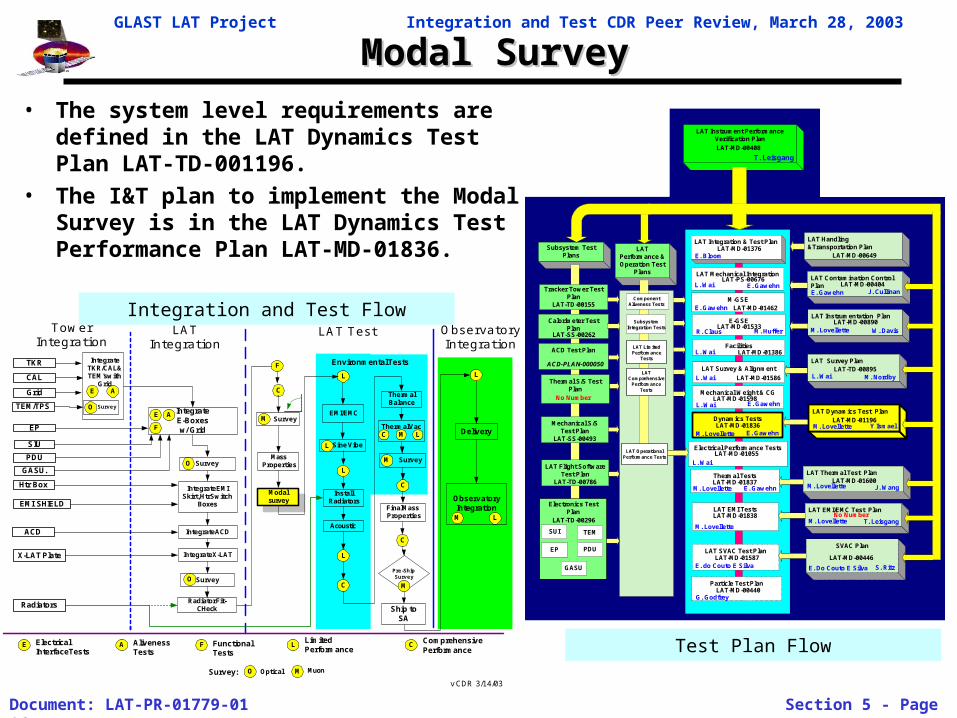
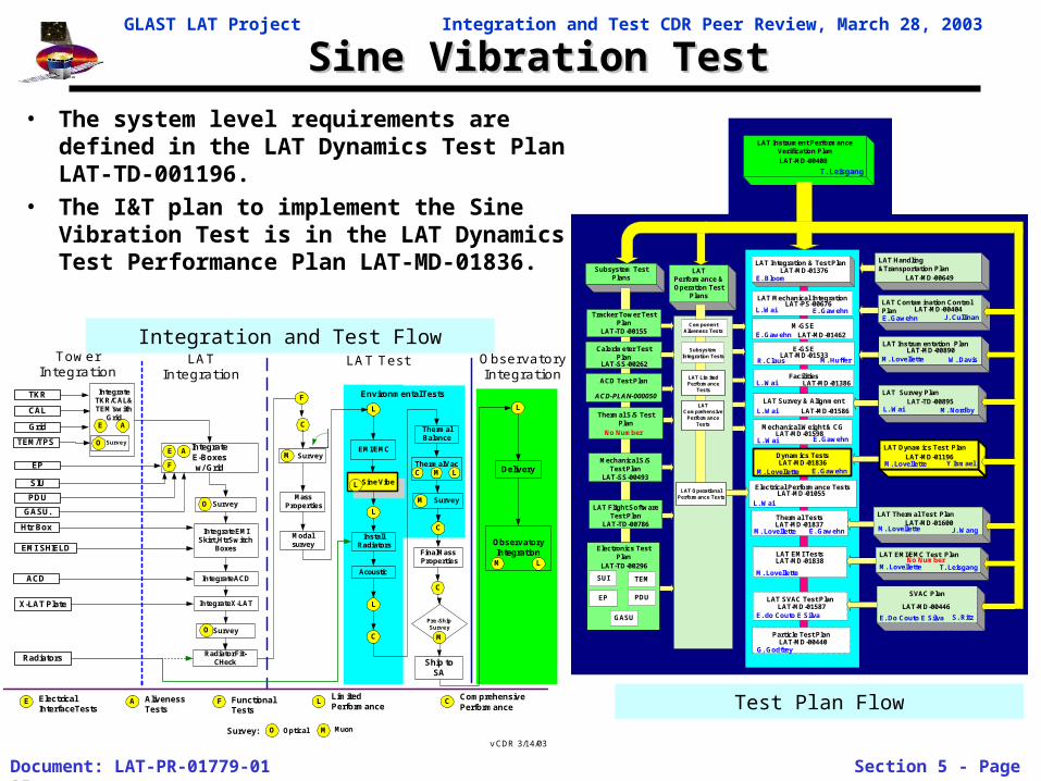
• The system level requirements are defined in the LAT Dynamics Test Plan LAT-TD-001196.
• The I&T plan to implement the Modal Survey is in the LAT Dynamics Test Performance Plan LAT-MD-01836.
GLAST LAT Project Integration and Test CDR Peer Review, March 28, 2003
Document: LAT-PR-01779-01 Section 5 - Page 17
LAT Modal SurveyLAT Modal Survey
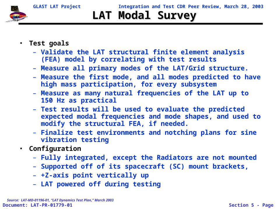
• Test goals– Validate the LAT structural finite element analysis (FEA) model by
correlating with test results– Measure all primary modes of the LAT/Grid structure. – Measure the first mode, and all modes predicted to have high
mass participation, for every subsystem– Measure as many natural frequencies of the LAT up to 150 Hz as
practical – Test results will be used to evaluate the predicted expected modal
frequencies and mode shapes, and used to modify the structural FEA, if needed.
– Finalize test environments and notching plans for sine vibration testing
• Configuration– Fully integrated, except the Radiators are not mounted– Supported off of its spacecraft (SC) mount brackets, – +Z-axis point vertically up– LAT powered off during testing
Source: LAT-MD-01196-01, “LAT Dynamics Test Plan,” March 2003
GLAST LAT Project Integration and Test CDR Peer Review, March 28, 2003
Document: LAT-PR-01779-01 Section 5 - Page 18
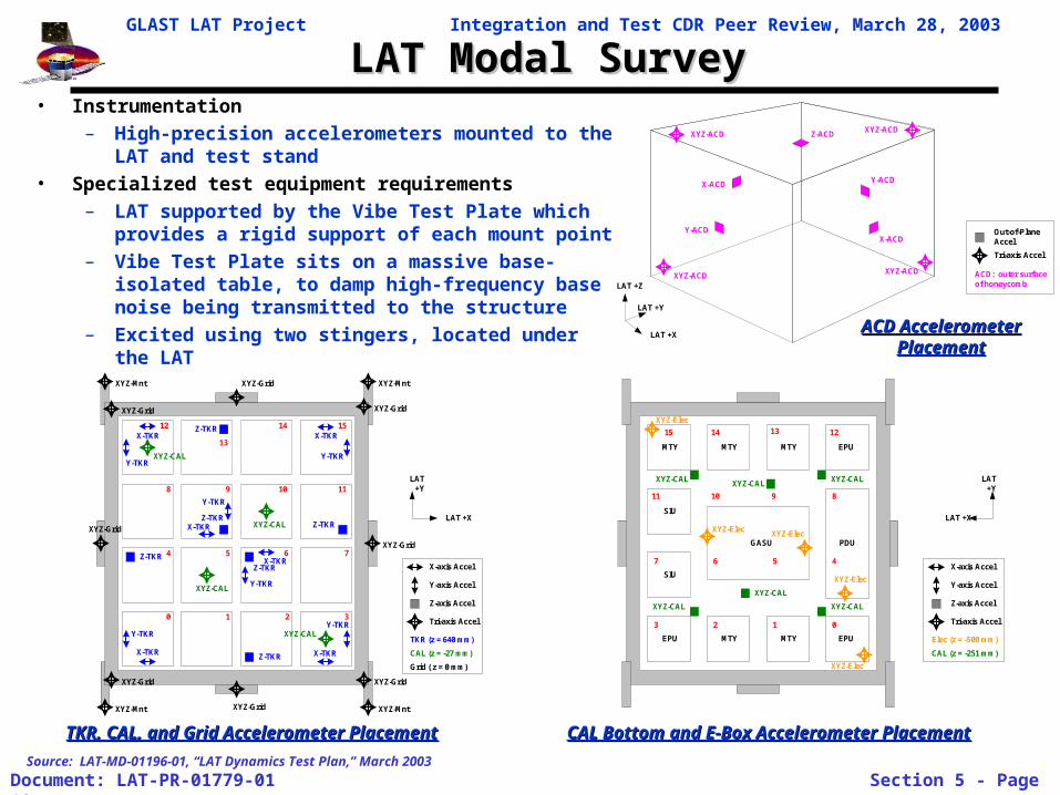
LAT Modal SurveyLAT Modal Survey• Instrumentation
– High-precision accelerometers mounted to the LAT and test stand
• Specialized test equipment requirements
– LAT supported by the Vibe Test Plate which provides a rigid support of each mount point
– Vibe Test Plate sits on a massive base-isolated table, to damp high-frequency base noise being transmitted to the structure
– Excited using two stingers, located under the LAT
LAT +X
LAT+Y
TKR (z = 640 mm)
CAL (z = -27 mm)
X-TKR
Y-TKR
Grid ( z = 0 mm)
X-TKR
X-TKR X-TKR
XYZ-CAL
XYZ-CAL
XYZ-CAL
XYZ-CAL
Z-TKR
Z-TKR
Z-TKR
Z-TKR
Z-TKR
Z-TKR
0 1 2 3
4
Y-TKR
Y-TKR
Y-TKR
Y-TKR
765
1098
1514
13
12
11
XYZ-Grid
XYZ-Grid
XYZ-Grid
XYZ-Grid
XYZ-Grid
XYZ-GridXYZ-Grid
XYZ-Grid
XYZ-Mnt XYZ-Mnt
XYZ-MntXYZ-Mnt
Y-TKR
X-TKR
X-TKR
X-axis Accel
Y-axis Accel
Tri-axis Accel
Z-axis Accel
Source: LAT-MD-01196-01, “LAT Dynamics Test Plan,” March 2003
LAT +Y
LAT +Z
ACD: outer surfaceof honeycomb
Tri-axis Accel
Out-of-PlaneAccel
LAT +X
Y-ACD
Z-ACD
X-ACD
Y-ACD
XYZ-ACD
XYZ-ACDXYZ-ACD
XYZ-ACD
X-ACD
LAT +X
LAT+Y
Elec (z = -500 mm)
CAL (z = -251 mm)
0123
47 6 5
10 9 8
15 14 13 12
11
X-axis Accel
Y-axis Accel
Tri-axis Accel
Z-axis Accel
PDU
SIU
SIU
EPU EPU
EPUMTY MTY MTY
MTY MTY
GASU
XYZ-CALXYZ-CAL
XYZ-CAL
XYZ-CAL
XYZ-CAL
XYZ-CAL
XYZ-Elec
XYZ-Elec
XYZ-Elec
XYZ-Elec
XYZ-Elec
ACD Accelerometer ACD Accelerometer PlacementPlacement
CAL Bottom and E-Box Accelerometer PlacementCAL Bottom and E-Box Accelerometer PlacementTKR, CAL, and Grid Accelerometer PlacementTKR, CAL, and Grid Accelerometer Placement
GLAST LAT Project Integration and Test CDR Peer Review, March 28, 2003
Document: LAT-PR-01779-01 Section 5 - Page 19
LAT Modal Survey TestLAT Modal Survey Test
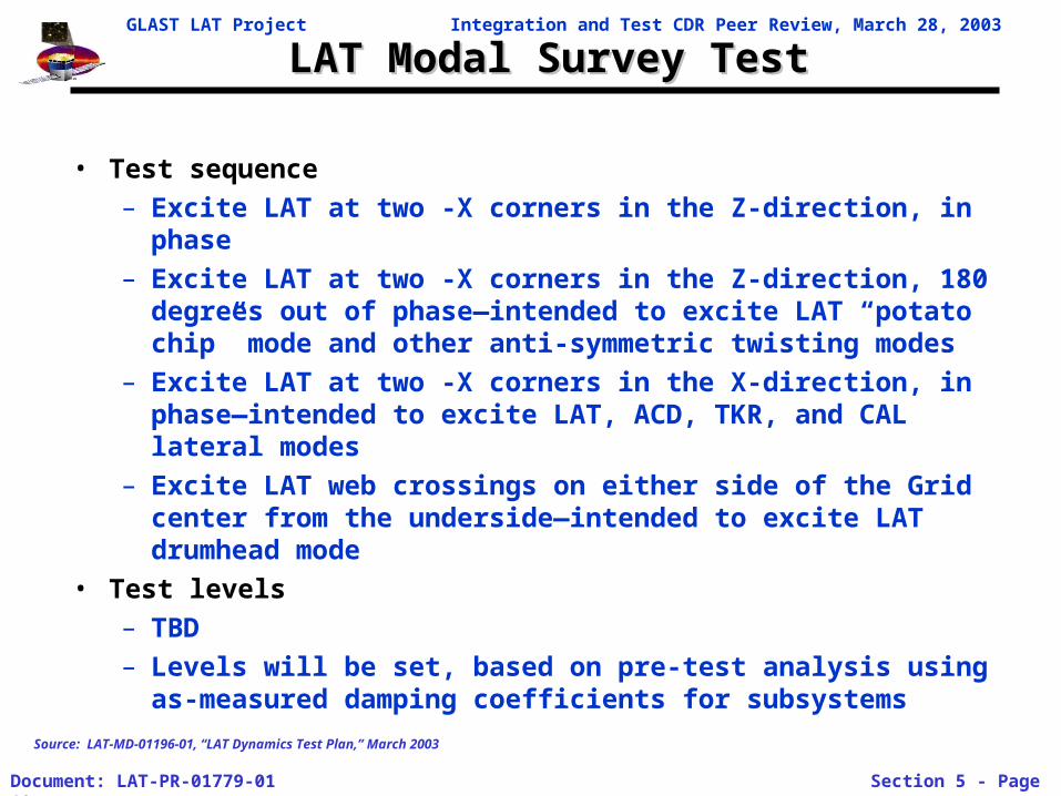
• Test sequence– Excite LAT at two -X corners in the Z-direction, in phase– Excite LAT at two -X corners in the Z-direction, 180 degrees
out of phase—intended to excite LAT “potato chip” mode and other anti-symmetric twisting modes
– Excite LAT at two -X corners in the X-direction, in phase—intended to excite LAT, ACD, TKR, and CAL lateral modes
– Excite LAT web crossings on either side of the Grid center from the underside—intended to excite LAT drumhead mode
• Test levels– TBD– Levels will be set, based on pre-test analysis using as-
measured damping coefficients for subsystems
Source: LAT-MD-01196-01, “LAT Dynamics Test Plan,” March 2003
GLAST LAT Project Integration and Test CDR Peer Review, March 28, 2003
Document: LAT-PR-01779-01 Section 5 - Page 20
Modal Test SetupModal Test Setup
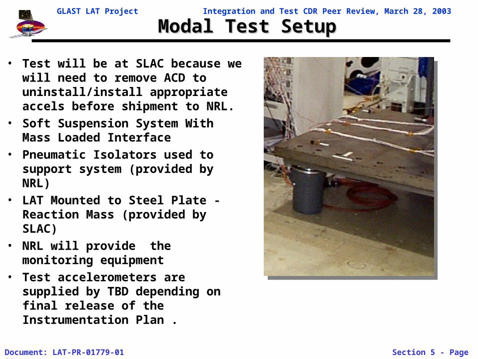
• Test will be at SLAC because we will need to remove ACD to uninstall/install appropriate accels before shipment to NRL.
• Soft Suspension System With Mass Loaded Interface
• Pneumatic Isolators used to support system (provided by NRL)
• LAT Mounted to Steel Plate - Reaction Mass (provided by SLAC)
• NRL will provide the monitoring equipment
• Test accelerometers are supplied by TBD depending on final release of the Instrumentation Plan .
GLAST LAT Project Integration and Test CDR Peer Review, March 28, 2003
Document: LAT-PR-01779-01 Section 5 - Page 21
EMI/EMC TestsEMI/EMC Tests
ObservatoryIntegration
Sine Vibe
TowerIntegration
LATIntegration
LAT Test ObservatoryIntegration
TKR
CAL
TEM/TPS
Grid
Radiators
EP
SIU
GASU.
PDU
ACD
IntegrateE-Boxesw/ Grid
Htr Box
Delivery
AlivenessTests
LimitedPerformance
X-LAT Plate
C
CLE A
A
MassProperties
EMI/EMC
L
InstallRadiators
Acoustic
L
C
Thermal Vac
ThermalBalance
C L
C
Final MassProperties
Pre-ShipSurvey
L
A
Ship toSA
F
F
F
EMI SHIELD
Survey Survey
M
O M
L
M
O Optical M Muon
IntegrateTKR/CAL &TEM's with
Grid
SurveyO
Integrate ACD
SurveyO
Integrate EMISkirt, Htr Switch
Boxes
Radiator Fit-CHeck
SurveyM
Modalsurvey
E
L
FunctionalTests
Survey:
L
ElectricalInterfaceTests
ComprehensivePerformance
Environmental Tests
E
M
C
v CDR 3/14/03
Integrate X-LAT
Test Plan Flow
Integration and Test Flow
LATPerformance &Operation Test
Plans
Subsystem TestPlans
LAT Instrument PerformanceVerification Plan
LAT Integration & Test Plan
LAT Contamination ControlPlan
Electrical Performance Tests
Dynamics Tests
LAT SVAC Test Plan
E. Bloom
M-GSE
Facilities
Tracker Tower TestPlan
LAT-TD-00155
Calorimeter TestPlan
ACD Test Plan
Thermal S/S TestPlan
Mechanical S/STest Plan
LAT-SS-00493
TEM
GASU
SUI
EP PDU
LAT EMI TestsElectronics Test
Plan
LAT Instrumentation Plan
W. Davis
ComponentAliveness Tests
SubsystemIntegration Tests
LAT LimitedPerformance
Tests
LATComprehensive
PerformanceTests
LAT OperationalPerformance Tests
E. Gawehn
L. Wai
E. GawehnM. Lovellette
L. Wai
M. Lovellette
E. do Couto E Silva
M. Lovellette
J. CullinanE. Gawehn
Particle Test Plan
G. Godfrey
LAT-MD-01376
LAT-MD-01462
E-GSE
M. Huffer
LAT-MD-01386
LAT-MD-01055
LAT-MD-00452
LAT-MD-00404
LAT-MD-00890
LAT-SS-00262
LAT-TD-00296
LAT-MD-00408
ACD-PLAN-000050
LAT Flight SoftwareTest Plan
LAT-TD-00786
SVAC Plan
E. Do Couto E Silva
LAT-MD-01587
LAT EMI/EMC Test Plan
T. LeisgangM. Lovellette
LAT Thermal Test Plan
J. WangM. LovelletteLAT-MD-01600
Thermal Tests
M. Lovellette E. GawehnLAT-MD-01837
LAT Dynamics Test Plan
Y IsmaelM. LovelletteLAT-MD-01196
Mechanical Weight & CG
E. GawehnLAT-MD-01598
L. Wai
LAT Survey & Alignment
L. Wai LAT-MD-01586
LAT Survey Plan
M. NordbyL. WaiLAT-TD-00895
LAT Handling&Transportation Plan
T. Leisgang
LAT-MD-01838
LAT-MD-00440
No Number
LAT-MD-00649
LAT-MD-01836
No Number
LAT Mechanical Integration
L. Wai E. GawehnLAT-PS-00676
R. ClausLAT-MD-01533
LAT-MD-00446
S. Ritz
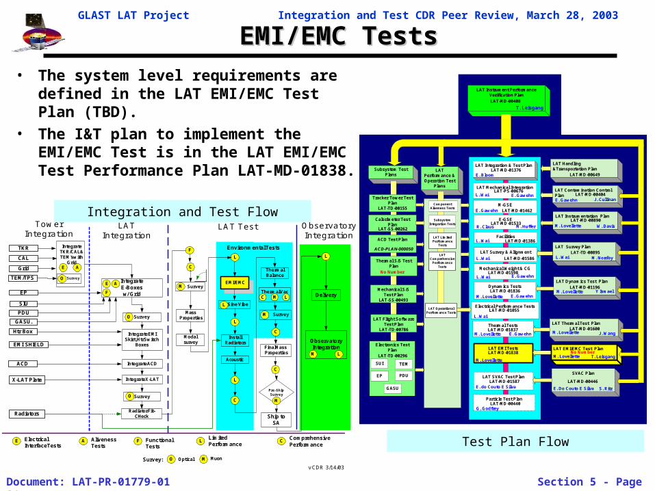
• The system level requirements are defined in the LAT EMI/EMC Test Plan (TBD).
• The I&T plan to implement the EMI/EMC Test is in the LAT EMI/EMC Test Performance Plan LAT-MD-01838.
GLAST LAT Project Integration and Test CDR Peer Review, March 28, 2003
Document: LAT-PR-01779-01 Section 5 - Page 22
EMI/EMC TestsEMI/EMC Tests
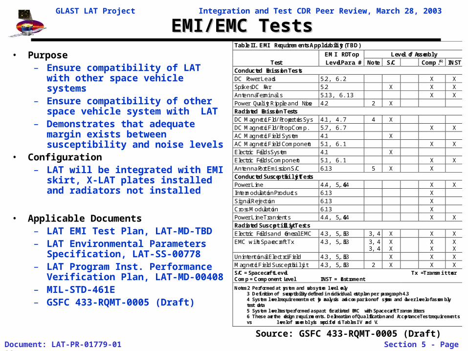
• Purpose– Ensure compatibility of LAT with
other space vehicle systems– Ensure compatibility of other space
vehicle system with LAT– Demonstrates that adequate margin
exists between susceptibility and noise levels
• Configuration– LAT will be integrated with EMI
skirt, X-LAT plates installed and radiators not installed
• Applicable Documents– LAT EMI Test Plan, LAT-MD-TBD– LAT Environmental Parameters
Specification, LAT-SS-00778– LAT Program Inst. Performance
Verification Plan, LAT-MD-00408– MIL-STD-461E– GSFC 433-RQMT-0005 (Draft)
Table II. EMI Requirements Applicability (TBD)
EMI RD Top Level of AssemblyTest Level Para. # Note S/C Comp.(6) INST
Conducted Emission TestsDC Power Leads 5.2, 6.2 X XSpikes DC Pwr 5.2 X X XAntenna Terminals 5.13, 6.13 X XPower Quality Ripple and Noise 4.2 2 XRadiated Emission TestsDC Magnetic Fld/Properties Sys 4.1, 4.7 4 XDC Magnetic Fld/Prop. Comp. 5.7, 6.7 X XAC Magnetic Field System 4.1 XAC Magnetic Field Component 5.1, 6.1 X XElectric Fields System 4.1 XElectric Fields Component 5.1, 6.1 X XAntenna Port Emission S/C 6.13 5 X XConducted Susceptibility TestsPower Line 4.4, 5.4, 6.4 X XIntermodulation Products 6.13 XSignal Rejection 6.13 XCross Modulation 6.13 XPower Line Transients 4.4, 5.4, 6.4 X XRadiated Susceptibility TestsElectric Fields and General EMC 4.3, 5.3, 6.3 3, 4 X X XEMC with Spacecraft Tx 4.3, 5.3, 6.3 3, 4
3, 4XX
XX
XX
Unintentional Electric Field 4.3, 5.3, 6.3 X X XMagnetic Field Susceptibility 4.3, 5.3, 6.3 2 X X XS/C = Spacecraft LevelComp = Component Level INST = Instrument
Tx = Transmitters
Notes 2 Performed at system and subsystem level only3 Definition of susceptibility defined in individual test plan per paragraph 4.34 System level requirement met by analysis and comparison of system and lower level of assemblytest data5 System level test performed as part of radiated EMC with Spacecraft Transmitters6 These are the design requirements. Delineation of Qualification and Acceptance Test requirementsvs level of assembly is specified in Tables IV and V.
Source: GSFC 433-RQMT-0005 (Draft)
GLAST LAT Project Integration and Test CDR Peer Review, March 28, 2003
Document: LAT-PR-01779-01 Section 5 - Page 23
EMI/EMC Test SuiteEMI/EMC Test Suite
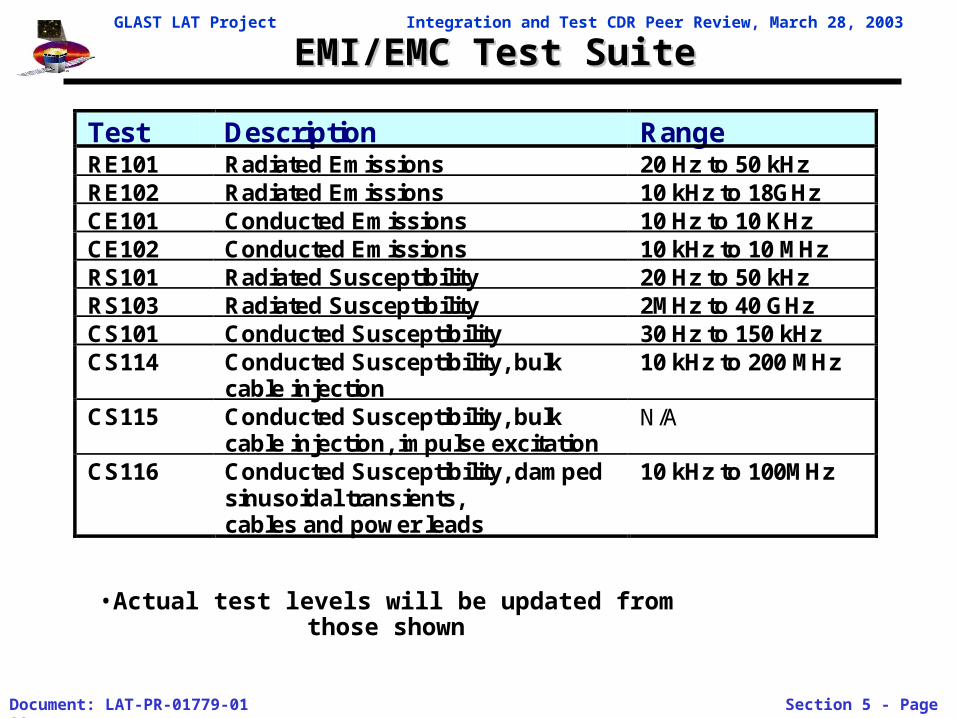
Test Description Range RE101 Radiated Emissions 20 Hz to 50 kHz RE102 Radiated Emissions 10 kHz to 18GHz CE101 Conducted Emissions 10 Hz to 10 KHz CE102 Conducted Emissions 10 kHz to 10 MHz RS101 Radiated Susceptibility 20 Hz to 50 kHz RS103 Radiated Susceptibility 2MHz to 40 GHz CS101 Conducted Susceptibility 30 Hz to 150 kHz CS114 Conducted Susceptibility, bulk
cable injection 10 kHz to 200 MHz
CS115 Conducted Susceptibility, bulk cable injection, impulse excitation
N/A
CS116 Conducted Susceptibility, damped sinusoidal transients, cables and power leads
10 kHz to 100MHz
•Actual test levels will be updated from those shown
GLAST LAT Project Integration and Test CDR Peer Review, March 28, 2003
Document: LAT-PR-01779-01 Section 5 - Page 24
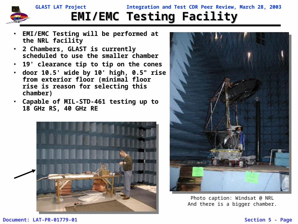
EMI/EMC Testing FacilityEMI/EMC Testing Facility• EMI/EMC Testing will be performed at the
NRL facility• 2 Chambers, GLAST is currently
scheduled to use the smaller chamber• 19' clearance tip to tip on the cones• door 10.5' wide by 10' high, 0.5" rise from
exterior floor (minimal floor rise is reason for selecting this chamber)
• Capable of MIL-STD-461 testing up to 18 GHz RS, 40 GHz RE
Photo caption: Windsat @ NRLAnd there is a bigger chamber.
GLAST LAT Project Integration and Test CDR Peer Review, March 28, 2003
Document: LAT-PR-01779-01 Section 5 - Page 25
Sine Vibration TestSine Vibration Test
ObservatoryIntegration
Sine Vibe
TowerIntegration
LATIntegration
LAT Test ObservatoryIntegration
TKR
CAL
TEM/TPS
Grid
Radiators
EP
SIU
GASU.
PDU
ACD
IntegrateE-Boxesw/ Grid
Htr Box
Delivery
AlivenessTests
LimitedPerformance
X-LAT Plate
C
CLE A
A
MassProperties
EMI/EMC
L
InstallRadiators
Acoustic
L
C
Thermal Vac
ThermalBalance
C L
C
Final MassProperties
Pre-ShipSurvey
L
A
Ship toSA
F
F
F
EMI SHIELD
Survey Survey
M
O M
L
M
O Optical M Muon
IntegrateTKR/CAL &TEM's with
Grid
SurveyO
Integrate ACD
SurveyO
Integrate EMISkirt, Htr Switch
Boxes
Radiator Fit-CHeck
SurveyM
Modalsurvey
E
L
FunctionalTests
Survey:
L
ElectricalInterfaceTests
ComprehensivePerformance
Environmental Tests
E
M
C
v CDR 3/14/03
Integrate X-LAT
Test Plan Flow
Integration and Test Flow
LATPerformance &Operation Test
Plans
Subsystem TestPlans
LAT Instrument PerformanceVerification Plan
LAT Integration & Test Plan
LAT Contamination ControlPlan
Electrical Performance Tests
Dynamics Tests
LAT SVAC Test Plan
E. Bloom
M-GSE
Facilities
Tracker Tower TestPlan
LAT-TD-00155
Calorimeter TestPlan
ACD Test Plan
Thermal S/S TestPlan
Mechanical S/STest Plan
LAT-SS-00493
TEM
GASU
SUI
EP PDU
LAT EMI TestsElectronics Test
Plan
LAT Instrumentation Plan
W. Davis
ComponentAliveness Tests
SubsystemIntegration Tests
LAT LimitedPerformance
Tests
LATComprehensive
PerformanceTests
LAT OperationalPerformance Tests
E. Gawehn
L. Wai
E. GawehnM. Lovellette
L. Wai
M. Lovellette
E. do Couto E Silva
M. Lovellette
J. CullinanE. Gawehn
Particle Test Plan
G. Godfrey
LAT-MD-01376
LAT-MD-01462
E-GSE
M. Huffer
LAT-MD-01386
LAT-MD-01055
LAT-MD-00452
LAT-MD-00404
LAT-MD-00890
LAT-SS-00262
LAT-TD-00296
LAT-MD-00408
ACD-PLAN-000050
LAT Flight SoftwareTest Plan
LAT-TD-00786
SVAC Plan
E. Do Couto E Silva
LAT-MD-01587
LAT EMI/EMC Test Plan
T. LeisgangM. Lovellette
LAT Thermal Test Plan
J. WangM. LovelletteLAT-MD-01600
Thermal Tests
M. Lovellette E. GawehnLAT-MD-01837
LAT Dynamics Test Plan
Y IsmaelM. LovelletteLAT-MD-01196
Mechanical Weight & CG
E. GawehnLAT-MD-01598
L. Wai
LAT Survey & Alignment
L. Wai LAT-MD-01586
LAT Survey Plan
M. NordbyL. WaiLAT-TD-00895
LAT Handling&Transportation Plan
T. Leisgang
LAT-MD-01838
LAT-MD-00440
No Number
LAT-MD-00649
LAT-MD-01836
No Number
LAT Mechanical Integration
L. Wai E. GawehnLAT-PS-00676
R. ClausLAT-MD-01533
LAT-MD-00446
S. Ritz
• The system level requirements are defined in the LAT Dynamics Test Plan LAT-TD-001196.
• The I&T plan to implement the Sine Vibration Test is in the LAT Dynamics Test Performance Plan LAT-MD-01836.
GLAST LAT Project Integration and Test CDR Peer Review, March 28, 2003
Document: LAT-PR-01779-01 Section 5 - Page 26
Sine Vibration TestSine Vibration Test
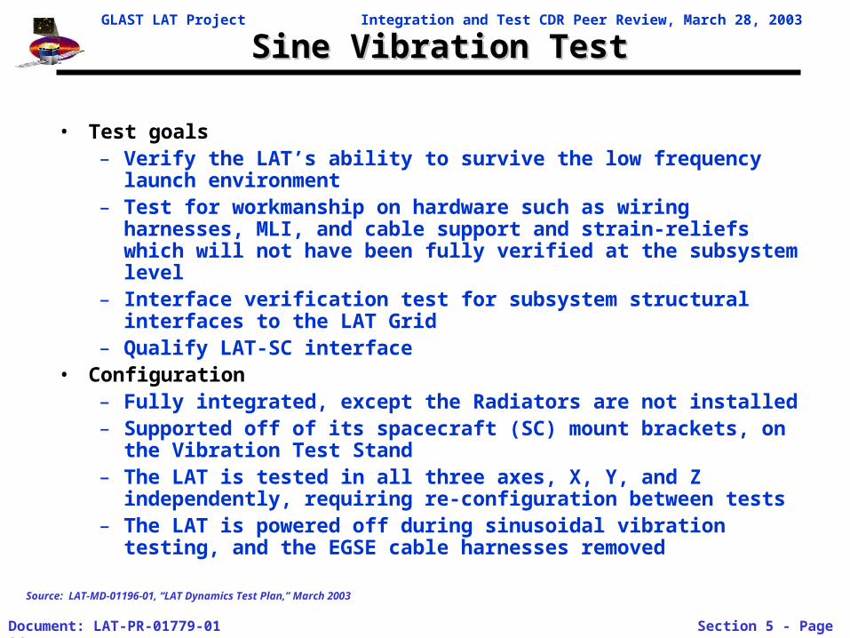
• Test goals– Verify the LAT’s ability to survive the low frequency launch
environment– Test for workmanship on hardware such as wiring harnesses, MLI,
and cable support and strain-reliefs which will not have been fully verified at the subsystem level
– Interface verification test for subsystem structural interfaces to the LAT Grid
– Qualify LAT-SC interface• Configuration
– Fully integrated, except the Radiators are not installed– Supported off of its spacecraft (SC) mount brackets, on the
Vibration Test Stand – The LAT is tested in all three axes, X, Y, and Z independently,
requiring re-configuration between tests– The LAT is powered off during sinusoidal vibration testing, and
the EGSE cable harnesses removed
Source: LAT-MD-01196-01, “LAT Dynamics Test Plan,” March 2003
GLAST LAT Project Integration and Test CDR Peer Review, March 28, 2003
Document: LAT-PR-01779-01 Section 5 - Page 27
Sine Vibration TestSine Vibration Test
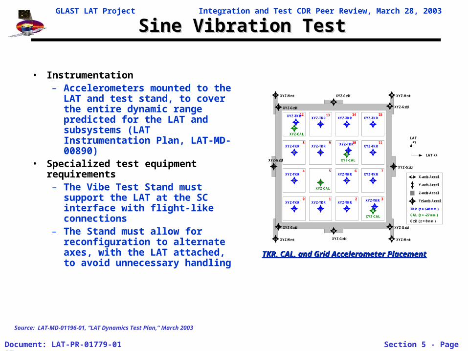
• Instrumentation– Accelerometers mounted to the
LAT and test stand, to cover the entire dynamic range predicted for the LAT and subsystems (LAT Instrumentation Plan, LAT-MD-00890)
• Specialized test equipment requirements– The Vibe Test Stand must
support the LAT at the SC interface with flight-like connections
– The Stand must allow for reconfiguration to alternate axes, with the LAT attached, to avoid unnecessary handling
LAT +X
LAT+Y
TKR (z = 640 mm)
CAL (z = -27 mm)
Grid ( z = 0 mm)
XYZ-CAL
XYZ-CAL
XYZ-CAL
XYZ-CAL
XYZ-TKR
0 1 2 3
4 765
1098
15141312
11
XYZ-Grid
XYZ-Grid
XYZ-Grid
XYZ-Grid
XYZ-Grid
XYZ-GridXYZ-Grid
XYZ-Grid
XYZ-Mnt XYZ-Mnt
XYZ-MntXYZ-Mnt
X-axis Accel
Y-axis Accel
Tri-axis Accel
Z-axis Accel
XYZ-TKRXYZ-TKR XYZ-TKR XYZ-TKR
XYZ-TKR XYZ-TKR XYZ-TKR
XYZ-TKR XYZ-TKR XYZ-TKR
XYZ-TKR XYZ-TKR XYZ-TKRXYZ-TKR
Source: LAT-MD-01196-01, “LAT Dynamics Test Plan,” March 2003
TKR, CAL, and Grid Accelerometer PlacementTKR, CAL, and Grid Accelerometer Placement
GLAST LAT Project Integration and Test CDR Peer Review, March 28, 2003
Document: LAT-PR-01779-01 Section 5 - Page 28
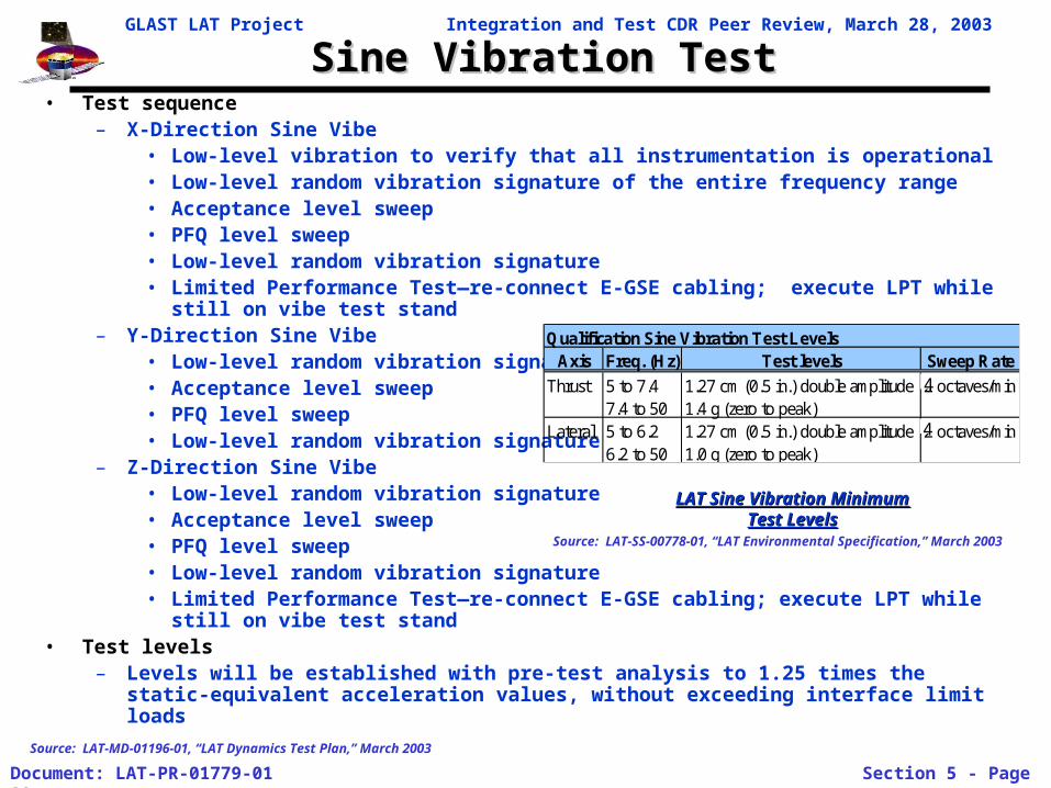
Sine Vibration TestSine Vibration Test• Test sequence
– X-Direction Sine Vibe• Low-level vibration to verify that all instrumentation is operational• Low-level random vibration signature of the entire frequency range• Acceptance level sweep• PFQ level sweep• Low-level random vibration signature• Limited Performance Test—re-connect E-GSE cabling; execute LPT while still on
vibe test stand– Y-Direction Sine Vibe
• Low-level random vibration signature• Acceptance level sweep• PFQ level sweep• Low-level random vibration signature
– Z-Direction Sine Vibe• Low-level random vibration signature• Acceptance level sweep• PFQ level sweep• Low-level random vibration signature• Limited Performance Test—re-connect E-GSE cabling; execute LPT while still on
vibe test stand• Test levels
– Levels will be established with pre-test analysis to 1.25 times the static-equivalent acceleration values, without exceeding interface limit loads
Qualification Sine Vibration Test LevelsAxis Freq. (Hz) Test levels Sweep Rate
Thrust 5 to 7.4 1.27 cm (0.5 in.) double amplitude 2 octaves/min7.4 to 50 1.4 g (zero to peak)
Lateral 5 to 6.2 1.27 cm (0.5 in.) double amplitude 2 octaves/min6.2 to 50 1.0 g (zero to peak)
LAT Sine Vibration Minimum LAT Sine Vibration Minimum Test LevelsTest Levels
Source: LAT-SS-00778-01, “LAT Environmental Specification,” March 2003
Source: LAT-MD-01196-01, “LAT Dynamics Test Plan,” March 2003
44
4
GLAST LAT Project Integration and Test CDR Peer Review, March 28, 2003
Document: LAT-PR-01779-01 Section 5 - Page 29
Sine Vibration Test FacilitySine Vibration Test Facility
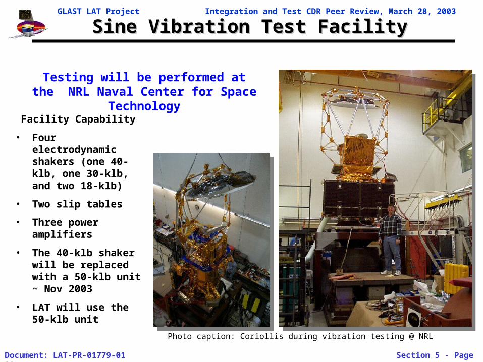
Facility Capability
• Four electrodynamic shakers (one 40-klb, one 30-klb, and two 18-klb)
• Two slip tables
• Three power amplifiers
• The 40-klb shaker will be replaced with a 50-klb unit ~ Nov 2003
• LAT will use the 50-klb unit
Photo caption: Coriollis during vibration testing @ NRL
Testing will be performed at the NRL Naval Center for Space Technology

GLAST LAT Project Integration and Test CDR Peer Review, March 28, 2003
Document: LAT-PR-01779-01 Section 5 - Page 30
Acoustic TestAcoustic Test
ObservatoryIntegration
Sine Vibe
TowerIntegration
LATIntegration
LAT Test ObservatoryIntegration
TKR
CAL
TEM/TPS
Grid
Radiators
EP
SIU
GASU.
PDU
ACD
IntegrateE-Boxesw/ Grid
Htr Box
Delivery
AlivenessTests
LimitedPerformance
X-LAT Plate
C
CLE A
A
MassProperties
EMI/EMC
L
InstallRadiators
Acoustic
L
C
Thermal Vac
ThermalBalance
C L
C
Final MassProperties
Pre-ShipSurvey
L
A
Ship toSA
F
F
F
EMI SHIELD
Survey Survey
M
O M
L
M
O Optical M Muon
IntegrateTKR/CAL &TEM's with
Grid
SurveyO
Integrate ACD
SurveyO
Integrate EMISkirt, Htr Switch
Boxes
Radiator Fit-CHeck
SurveyM
Modalsurvey
E
L
FunctionalTests
Survey:
L
ElectricalInterfaceTests
ComprehensivePerformance
Environmental Tests
E
M
C
v CDR 3/14/03
Integrate X-LAT
Test Plan Flow
Integration and Test Flow
LATPerformance &Operation Test
Plans
Subsystem TestPlans
LAT Instrument PerformanceVerification Plan
LAT Integration & Test Plan
LAT Contamination ControlPlan
Electrical Performance Tests
Dynamics Tests
LAT SVAC Test Plan
E. Bloom
M-GSE
Facilities
Tracker Tower TestPlan
LAT-TD-00155
Calorimeter TestPlan
ACD Test Plan
Thermal S/S TestPlan
Mechanical S/STest Plan
LAT-SS-00493
TEM
GASU
SUI
EP PDU
LAT EMI TestsElectronics Test
Plan
LAT Instrumentation Plan
W. Davis
ComponentAliveness Tests
SubsystemIntegration Tests
LAT LimitedPerformance
Tests
LATComprehensive
PerformanceTests
LAT OperationalPerformance Tests
E. Gawehn
L. Wai
E. GawehnM. Lovellette
L. Wai
M. Lovellette
E. do Couto E Silva
M. Lovellette
J. CullinanE. Gawehn
Particle Test Plan
G. Godfrey
LAT-MD-01376
LAT-MD-01462
E-GSE
M. Huffer
LAT-MD-01386
LAT-MD-01055
LAT-MD-00452
LAT-MD-00404
LAT-MD-00890
LAT-SS-00262
LAT-TD-00296
LAT-MD-00408
ACD-PLAN-000050
LAT Flight SoftwareTest Plan
LAT-TD-00786
SVAC Plan
E. Do Couto E Silva
LAT-MD-01587
LAT EMI/EMC Test Plan
T. LeisgangM. Lovellette
LAT Thermal Test Plan
J. WangM. LovelletteLAT-MD-01600
Thermal Tests
M. Lovellette E. GawehnLAT-MD-01837
LAT Dynamics Test Plan
Y IsmaelM. LovelletteLAT-MD-01196
Mechanical Weight & CG
E. GawehnLAT-MD-01598
L. Wai
LAT Survey & Alignment
L. Wai LAT-MD-01586
LAT Survey Plan
M. NordbyL. WaiLAT-TD-00895
LAT Handling&Transportation Plan
T. Leisgang
LAT-MD-01838
LAT-MD-00440
No Number
LAT-MD-00649
LAT-MD-01836
No Number
LAT Mechanical Integration
L. Wai E. GawehnLAT-PS-00676
R. ClausLAT-MD-01533
LAT-MD-00446
S. Ritz
• The system level requirements are defined in the LAT Dynamics Test Plan LAT-TD-001196.
• The I&T plan to implement the Acoustic Test is in the LAT Dynamics Test Performance Plan LAT-MD-01836.
GLAST LAT Project Integration and Test CDR Peer Review, March 28, 2003
Document: LAT-PR-01779-01 Section 5 - Page 31
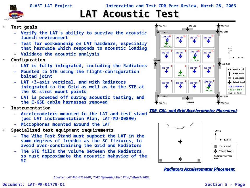
LAT Acoustic TestLAT Acoustic Test• Test goals
– Verify the LAT’s ability to survive the acoustic launch environment
– Test for workmanship on LAT hardware, especially that hardware which responds to acoustic loading
– Validate the acoustic analysis• Configuration
– LAT is fully integrated, including the Radiators– Mounted to STE using the flight-configuration bolted
joint– LAT +Z-axis vertical, and with Radiators integrated to
the Grid as well as to the STE at the SC strut mount points
– LAT is powered off during acoustic testing, and the E-GSE cable harnesses removed
• Instrumentation – Accelerometers mounted to the LAT and test stand
(per LAT Instrumentation Plan, LAT-MD-00890)– Microphones mounted around the LAT
• Specialized test equipment requirements– The Vibe Test Stand must support the LAT in the
same degrees of freedom as the SC flexures, to avoid over-constraining the Grid and Radiators
– The STE fills the volume between the Radiators, so must approximate the acoustic behavior of the SC
LAT +X
LAT+Y
TKR (z = 640 mm)
CAL (z = -27 mm)
Grid ( z = 0 mm)
XYZ-CAL
XYZ-CAL
XYZ-CAL
XYZ-CAL
XYZ-TKR
0 1 2 3
4 765
1098
15141312
11
XYZ-Grid
XYZ-Grid
XYZ-Grid
XYZ-Grid
XYZ-Grid
XYZ-GridXYZ-Grid
XYZ-Grid
XYZ-Mnt XYZ-Mnt
XYZ-MntXYZ-Mnt
X-axis Accel
Y-axis Accel
Tri-axis Accel
Z-axis Accel
XYZ-TKRXYZ-TKR XYZ-TKR XYZ-TKR
XYZ-TKR XYZ-TKR XYZ-TKR
XYZ-TKR XYZ-TKR XYZ-TKR
XYZ-TKR XYZ-TKR XYZ-TKRXYZ-TKR
LAT +X
LAT +Z
Radiator Inner Facesheet
Tri-axis Accel
Y-axis Accel
TKR, CAL, and Grid Accelerometer PlacementTKR, CAL, and Grid Accelerometer Placement
Radiators Accelerometer PlacementRadiators Accelerometer Placement
Source: LAT-MD-01196-01, “LAT Dynamics Test Plan,” March 2003
GLAST LAT Project Integration and Test CDR Peer Review, March 28, 2003
Document: LAT-PR-01779-01 Section 5 - Page 32
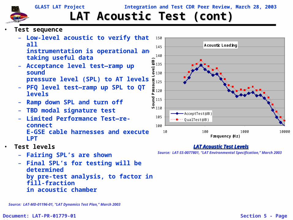
LAT Acoustic Test (cont)LAT Acoustic Test (cont)• Test sequence
– Low-level acoustic to verify that allinstrumentation is operational andtaking useful data
– Acceptance level test—ramp up soundpressure level (SPL) to AT levels
– PFQ level test—ramp up SPL to QTlevels
– Ramp down SPL and turn off– TBD modal signature test– Limited Performance Test—re-connect
E-GSE cable harnesses and execute LPT
• Test levels– Fairing SPL’s are shown– Final SPL’s for testing will be
determinedby pre-test analysis, to factor in fill-fractionin acoustic chamber
Acoustic Loading
100
105
110
115
120
125
130
135
140
145
150
10 100 1000 10000Frequency (Hz)
So
un
d P
ress
ure
Lev
el (
dB
)
Accept Tes t (dB)
Qual Tes t (dB)
LAT Acoustic Test LevelsLAT Acoustic Test LevelsSource: LAT-SS-0077801, “LAT Environmental Specification,” March 2003
Source: LAT-MD-01196-01, “LAT Dynamics Test Plan,” March 2003
GLAST LAT Project Integration and Test CDR Peer Review, March 28, 2003
Document: LAT-PR-01779-01 Section 5 - Page 33
NRL Acoustic Chamber NRL Acoustic Chamber
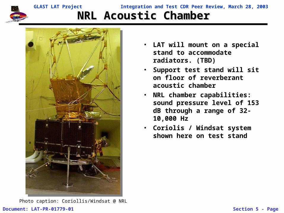
• LAT will mount on a special stand to accommodate radiators. (TBD)
• Support test stand will sit on floor of reverberant acoustic chamber
• NRL chamber capabilities: sound pressure level of 153 dB through a range of 32-10,000 Hz
• Coriolis / Windsat system shown here on test stand
Photo caption: Coriollis/Windsat @ NRL
GLAST LAT Project Integration and Test CDR Peer Review, March 28, 2003
Document: LAT-PR-01779-01 Section 5 - Page 34
LAT Thermal Balance/Thermal-Vacuum TestsLAT Thermal Balance/Thermal-Vacuum Tests
ObservatoryIntegration
Sine Vibe
TowerIntegration
LATIntegration
LAT Test ObservatoryIntegration
TKR
CAL
TEM/TPS
Grid
Radiators
EP
SIU
GASU.
PDU
ACD
IntegrateE-Boxesw/ Grid
Htr Box
Delivery
AlivenessTests
LimitedPerformance
X-LAT Plate
C
CLE A
A
MassProperties
EMI/EMC
L
InstallRadiators
Acoustic
L
C
Thermal Vac
ThermalBalance
C L
C
Final MassProperties
Pre-ShipSurvey
L
A
Ship toSA
F
F
F
EMI SHIELD
Survey Survey
M
O M
L
M
O Optical M Muon
IntegrateTKR/CAL &TEM's with
Grid
SurveyO
Integrate ACD
SurveyO
Integrate EMISkirt, Htr Switch
Boxes
Radiator Fit-CHeck
SurveyM
Modalsurvey
E
L
FunctionalTests
Survey:
L
ElectricalInterfaceTests
ComprehensivePerformance
Environmental Tests
E
M
C
v CDR 3/14/03
Integrate X-LAT
Test Plan Flow
Integration and Test Flow
LATPerformance &Operation Test
Plans
Subsystem TestPlans
LAT Instrument PerformanceVerification Plan
LAT Integration & Test Plan
LAT Contamination ControlPlan
Electrical Performance Tests
Dynamics Tests
LAT SVAC Test Plan
E. Bloom
M-GSE
Facilities
Tracker Tower TestPlan
LAT-TD-00155
Calorimeter TestPlan
ACD Test Plan
Thermal S/S TestPlan
Mechanical S/STest Plan
LAT-SS-00493
TEM
GASU
SUI
EP PDU
LAT EMI TestsElectronics Test
Plan
LAT Instrumentation Plan
W. Davis
ComponentAliveness Tests
SubsystemIntegration Tests
LAT LimitedPerformance
Tests
LATComprehensive
PerformanceTests
LAT OperationalPerformance Tests
E. Gawehn
L. Wai
E. GawehnM. Lovellette
L. Wai
M. Lovellette
E. do Couto E Silva
M. Lovellette
J. CullinanE. Gawehn
Particle Test Plan
G. Godfrey
LAT-MD-01376
LAT-MD-01462
E-GSE
M. Huffer
LAT-MD-01386
LAT-MD-01055
LAT-MD-00452
LAT-MD-00404
LAT-MD-00890
LAT-SS-00262
LAT-TD-00296
LAT-MD-00408
ACD-PLAN-000050
LAT Flight SoftwareTest Plan
LAT-TD-00786
SVAC Plan
E. Do Couto E Silva
LAT-MD-01587
LAT EMI/EMC Test Plan
T. LeisgangM. Lovellette
LAT Thermal Test Plan
J. WangM. LovelletteLAT-MD-01600
Thermal Tests
M. Lovellette E. GawehnLAT-MD-01837
LAT Dynamics Test Plan
Y IsmaelM. LovelletteLAT-MD-01196
Mechanical Weight & CG
E. GawehnLAT-MD-01598
L. Wai
LAT Survey & Alignment
L. Wai LAT-MD-01586
LAT Survey Plan
M. NordbyL. WaiLAT-TD-00895
LAT Handling&Transportation Plan
T. Leisgang
LAT-MD-01838
LAT-MD-00440
No Number
LAT-MD-00649
LAT-MD-01836
No Number
LAT Mechanical Integration
L. Wai E. GawehnLAT-PS-00676
R. ClausLAT-MD-01533
LAT-MD-00446
S. Ritz
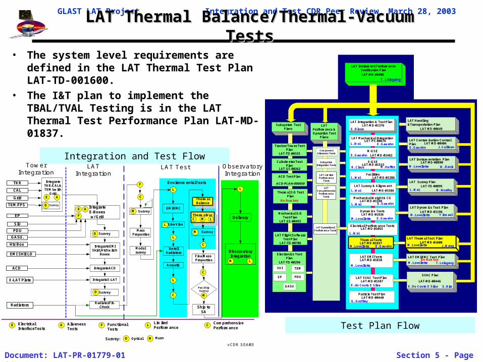
• The system level requirements are defined in the LAT Thermal Test Plan LAT-TD-001600.
• The I&T plan to implement the TBAL/TVAL Testing is in the LAT Thermal Test Performance Plan LAT-MD-01837.
GLAST LAT Project Integration and Test CDR Peer Review, March 28, 2003
Document: LAT-PR-01779-01 Section 5 - Page 35
LAT Thermal Balance/Thermal-Vacuum TestsLAT Thermal Balance/Thermal-Vacuum Tests
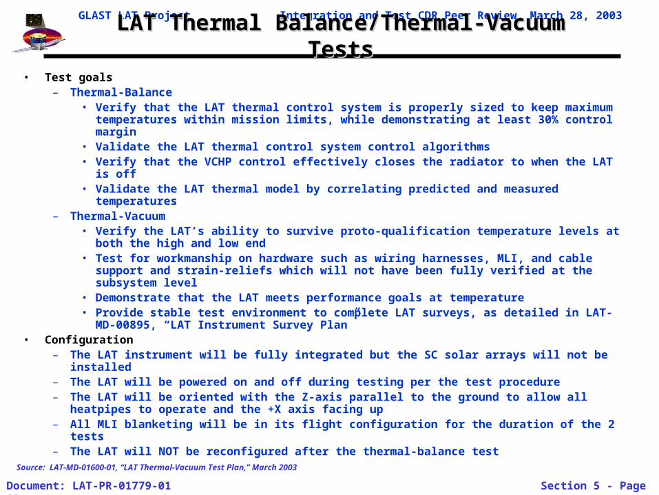
• Test goals– Thermal-Balance
• Verify that the LAT thermal control system is properly sized to keep maximum temperatures within mission limits, while demonstrating at least 30% control margin
• Validate the LAT thermal control system control algorithms• Verify that the VCHP control effectively closes the radiator to when the LAT is off• Validate the LAT thermal model by correlating predicted and measured temperatures
– Thermal-Vacuum• Verify the LAT’s ability to survive proto-qualification temperature levels at both the
high and low end• Test for workmanship on hardware such as wiring harnesses, MLI, and cable support
and strain-reliefs which will not have been fully verified at the subsystem level• Demonstrate that the LAT meets performance goals at temperature• Provide stable test environment to complete LAT surveys, as detailed in LAT-MD-
00895, “LAT Instrument Survey Plan”• Configuration
– The LAT instrument will be fully integrated but the SC solar arrays will not be installed– The LAT will be powered on and off during testing per the test procedure– The LAT will be oriented with the Z-axis parallel to the ground to allow all heatpipes to
operate and the +X axis facing up– All MLI blanketing will be in its flight configuration for the duration of the 2 tests– The LAT will NOT be reconfigured after the thermal-balance test
Source: LAT-MD-01600-01, “LAT Thermal-Vacuum Test Plan,” March 2003
GLAST LAT Project Integration and Test CDR Peer Review, March 28, 2003
Document: LAT-PR-01779-01 Section 5 - Page 36
LAT Thermal Balance/Thermal-Vacuum TestsLAT Thermal Balance/Thermal-Vacuum Tests
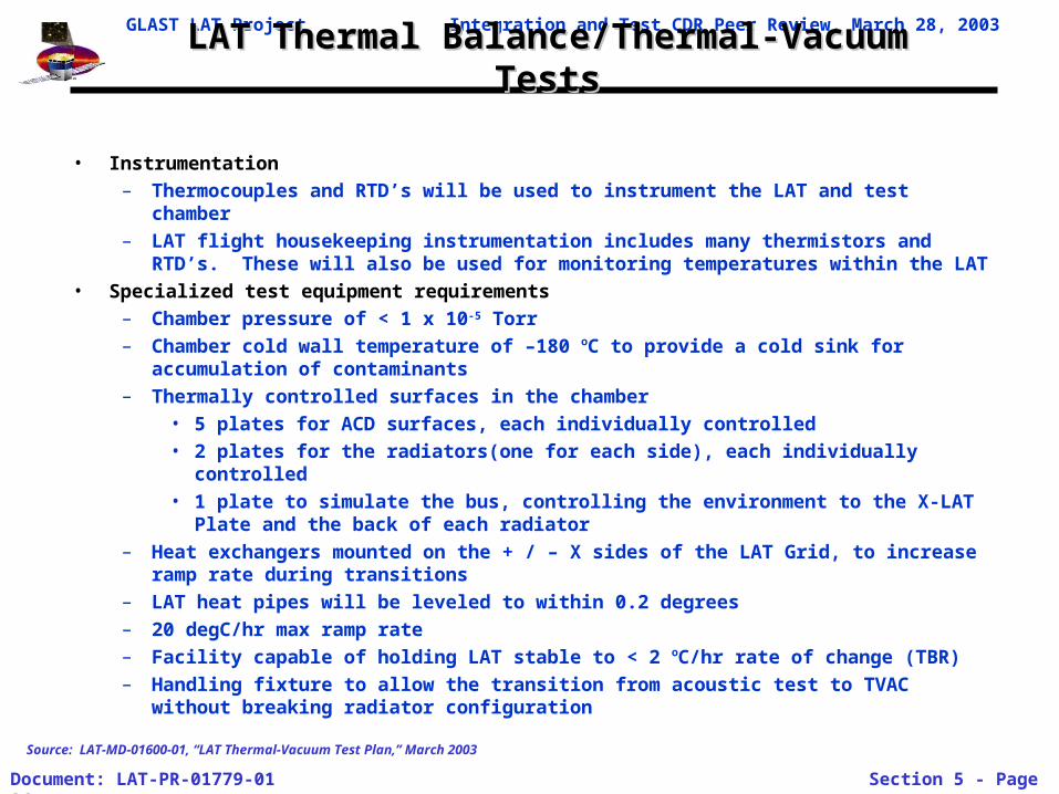
• Instrumentation
– Thermocouples and RTD’s will be used to instrument the LAT and test chamber
– LAT flight housekeeping instrumentation includes many thermistors and RTD’s. These will also be used for monitoring temperatures within the LAT
• Specialized test equipment requirements
– Chamber pressure of < 1 x 10⁻⁵ Torr
– Chamber cold wall temperature of –180 oC to provide a cold sink for accumulation of contaminants
– Thermally controlled surfaces in the chamber
• 5 plates for ACD surfaces, each individually controlled
• 2 plates for the radiators(one for each side), each individually controlled
• 1 plate to simulate the bus, controlling the environment to the X-LAT Plate and the back of each radiator
– Heat exchangers mounted on the + / – X sides of the LAT Grid, to increase ramp rate during transitions
– LAT heat pipes will be leveled to within 0.2 degrees
– 20 degC/hr max ramp rate
– Facility capable of holding LAT stable to < 2 oC/hr rate of change (TBR)
– Handling fixture to allow the transition from acoustic test to TVAC without breaking radiator configuration
Source: LAT-MD-01600-01, “LAT Thermal-Vacuum Test Plan,” March 2003
GLAST LAT Project Integration and Test CDR Peer Review, March 28, 2003
Document: LAT-PR-01779-01 Section 5 - Page 37
LAT Thermal Balance/Thermal-Vacuum Test ProfileLAT Thermal Balance/Thermal-Vacuum Test Profile
• Dwell at high and low temps for 12 hours, min• Limited Performance Tests conducted during transitions• Comprehensive Performance Tests (C)
– CPT test regime performed at ambient, during cold and hot soaks, and at return to ambient
• Limited Performance Tests (L)– LPT test regime performed as indicated. Operating modes
will be checked and units will be monitored for failure and intermittent operation
Source: LAT-MD-01600-01, “LAT Thermal-Vacuum Test Plan,” March 2003
GLAST LAT Project Integration and Test CDR Peer Review, March 28, 2003
Document: LAT-PR-01779-01 Section 5 - Page 38
LAT Thermal Balance/Thermal-Vacuum Test ProfileLAT Thermal Balance/Thermal-Vacuum Test Profile
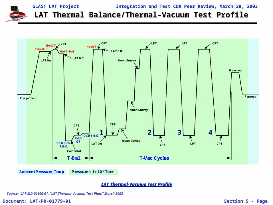
LAT Thermal-Vacuum Test ProfileLAT Thermal-Vacuum Test Profile
Source: LAT-MD-01600-01, “LAT Thermal-Vacuum Test Plan,” March 2003
T-Vac Cycles
1 2 3 4
Bake OutHot T- Bal
Cold T-Bal
Cold SurvT-Bal
Ambient Pressure, Temp Pressure < 1x 10⁻⁵ Torr
T-Bal
Pump-Down Repress
Warm-up
Hot QT
ColdQT
LAT Off
CPT
Cold Start
CPT
CPT CPT
LAT Off
Muon Survey
Muon Survey
Muon Survey
LPT LPT CPT
LPT LPT CPT
LAT On
LAT On
Hot QT
GLAST LAT Project Integration and Test CDR Peer Review, March 28, 2003
Document: LAT-PR-01779-01 Section 5 - Page 39
Thermal Test FacilityThermal Test Facility
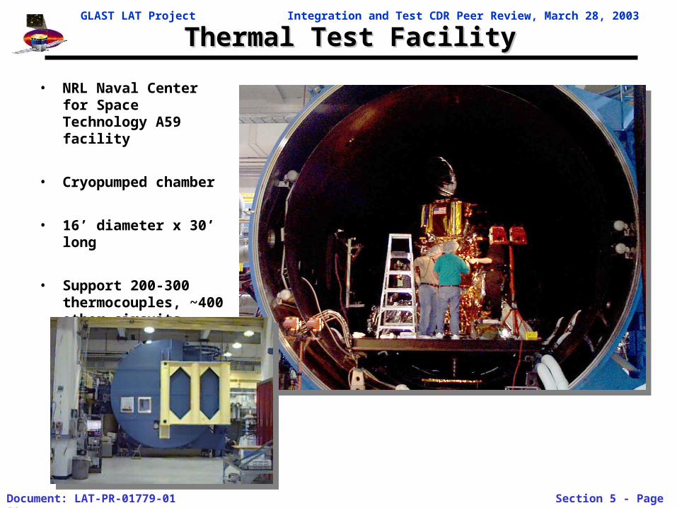
• NRL Naval Center for Space Technology A59 facility
• Cryopumped chamber
• 16’ diameter x 30’ long
• Support 200-300 thermocouples, ~400 other circuits
GLAST LAT Project Integration and Test CDR Peer Review, March 28, 2003
Document: LAT-PR-01779-01 Section 5 - Page 40
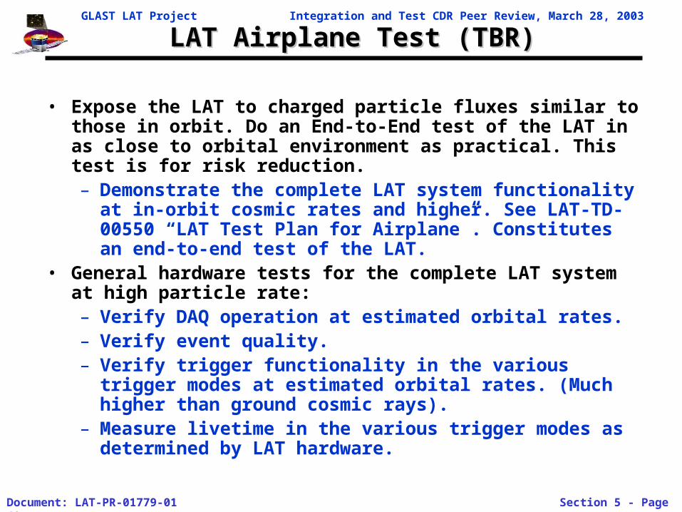
LAT Airplane Test (TBR)LAT Airplane Test (TBR)
• Expose the LAT to charged particle fluxes similar to those in orbit. Do an End-to-End test of the LAT in as close to orbital environment as practical. This test is for risk reduction.– Demonstrate the complete LAT system functionality at in-
orbit cosmic rates and higher. See LAT-TD-00550 “LAT Test Plan for Airplane”. Constitutes an end-to-end test of the LAT.
• General hardware tests for the complete LAT system at high particle rate:– Verify DAQ operation at estimated orbital rates.– Verify event quality. – Verify trigger functionality in the various trigger modes at
estimated orbital rates. (Much higher than ground cosmic rays).
– Measure livetime in the various trigger modes as determined by LAT hardware.
GLAST LAT Project Integration and Test CDR Peer Review, March 28, 2003
Document: LAT-PR-01779-01 Section 5 - Page 41
EXTRA SLIDE
GLAST LAT Project Integration and Test CDR Peer Review, March 28, 2003
Document: LAT-PR-01779-01 Section 5 - Page 42
Pass/Fail CriteriaPass/Fail Criteria
• Modal Survey:
– Successful correlation of dynamics model
• EMI/EMC:
– Emissions for the LAT below required levels Susceptibility: LAT does not exhibit susceptibility when exposed to required levels
• Sine vibe:
– No change in modal frequencies
– LAT functions properly post test
• Thermal Balance:
– successful correlation of thermal model
• Thermal vacuum testing:
– Verify ability to operate successfully over required temperature range
– Successful completion of performance tests
– Successful completion of cosmic ray muon survey