Embed Size (px)
Citation preview
GLAST LAT Project CDR/CD-3 Review, May 12-15, 2003
LAT-PR-01967 4.1.7 Electronics, DAQ, FSW 1
GLAST Large Area Telescope:GLAST Large Area Telescope:
Electronics, Data Acquisition & Flight Software
Gunther HallerStanford Linear Accelerator CenterManager, Electronics, DAQ & FSWLAT Chief Electronics Engineer
[email protected](650) 926-4257
GammaGamma--ray Large ray Large Area Space Area Space TelescopeTelescope
GLAST LAT Project CDR/CD-3 Review, May 12-15, 2003
LAT-PR-01967 4.1.7 Electronics, DAQ, FSW 2
OutlineOutline
• Management & System Engineering• Components & Assemblies• Thermal & Mechanical• Verification & Test• Fabrication• Risks• Budget & Schedule
GLAST LAT Project CDR/CD-3 Review, May 12-15, 2003
LAT-PR-01967 4.1.7 Electronics, DAQ, FSW 3
Management & System EngineeringManagement & System Engineering
GLAST LAT Project CDR/CD-3 Review, May 12-15, 2003
LAT-PR-01967 4.1.7 Electronics, DAQ, FSW 4
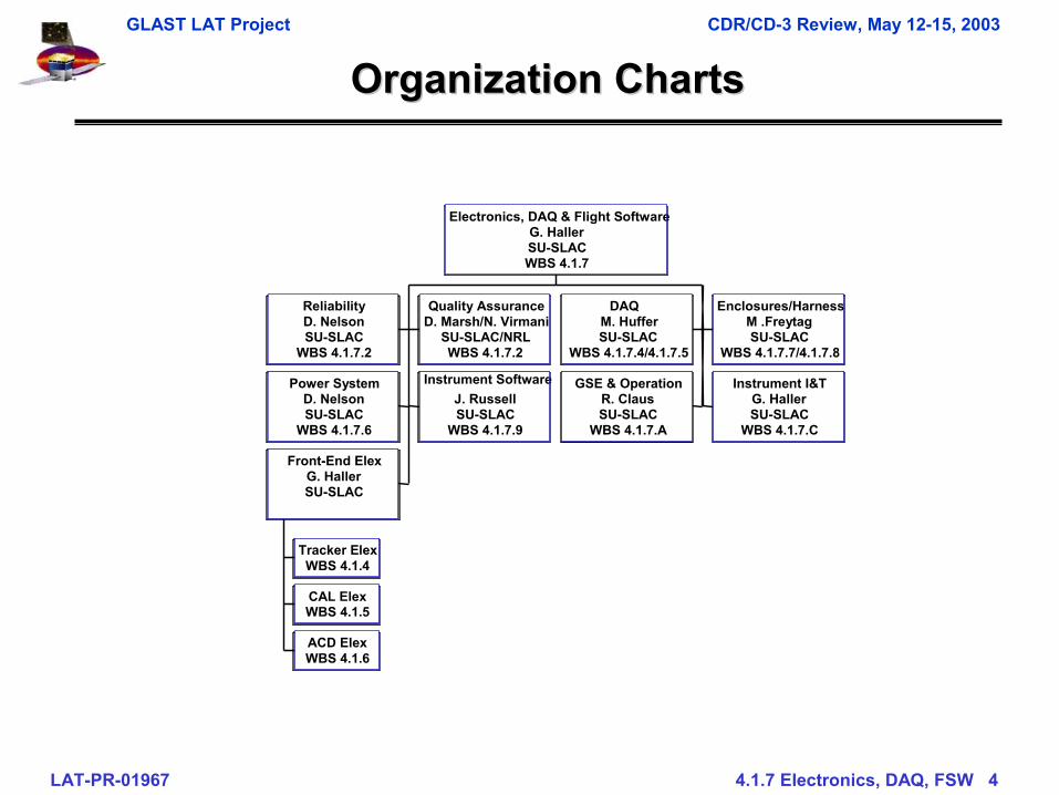
Organization ChartsOrganization Charts
ReliabilityD. NelsonSU-SLAC
WBS 4.1.7.2
Quality AssuranceD. Marsh/N. Virmani
SU-SLAC/NRLWBS 4.1.7.2
DAQM. HufferSU-SLAC
WBS 4.1.7.4/4.1.7.5
Enclosures/HarnessM .FreytagSU-SLAC
WBS 4.1.7.7/4.1.7.8
Power SystemD. NelsonSU-SLAC
WBS 4.1.7.6
Instrument SoftwareJ. RussellSU-SLAC
WBS 4.1.7.9
GSE & OperationR. ClausSU-SLAC
WBS 4.1.7.A
Instrument I&TG. HallerSU-SLAC
WBS 4.1.7.C
Tracker ElexWBS 4.1.4
CAL ElexWBS 4.1.5
ACD ElexWBS 4.1.6
Front-End ElexG. HallerSU-SLAC
Electronics, DAQ & Flight SoftwareG. HallerSU-SLACWBS 4.1.7
GLAST LAT Project CDR/CD-3 Review, May 12-15, 2003
LAT-PR-01967 4.1.7 Electronics, DAQ, FSW 5
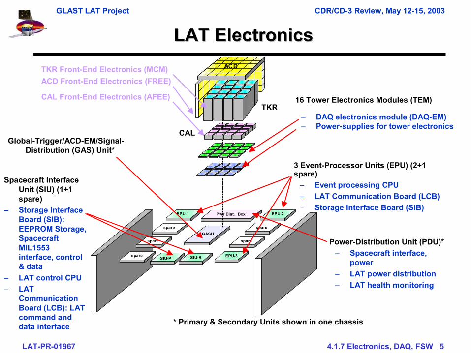
LAT ElectronicsLAT Electronics
16 Tower Electronics Modules (TEM)
– DAQ electronics module (DAQ-EM)– Power-supplies for tower electronics
* Primary & Secondary Units shown in one chassis
ACD
spare
EPU-3
EPU-2EPU-1
spare spare
Pwr Dist. Box
GASU
spare
spare
SIU-P SIU-R
3 Event-Processor Units (EPU) (2+1 spare)
– Event processing CPU– LAT Communication Board (LCB)– Storage Interface Board (SIB)
Spacecraft Interface Unit (SIU) (1+1 spare)
– Storage Interface Board (SIB): EEPROM Storage, Spacecraft MIL1553 interface, control & data
– LAT control CPU– LAT
Communication Board (LCB): LAT command and data interface
Power-Distribution Unit (PDU)*– Spacecraft interface,
power– LAT power distribution– LAT health monitoring
Global-Trigger/ACD-EM/Signal-Distribution (GAS) Unit*
TKR
CAL
TKR Front-End Electronics (MCM)ACD Front-End Electronics (FREE)
CAL Front-End Electronics (AFEE)
GLAST LAT Project CDR/CD-3 Review, May 12-15, 2003
LAT-PR-01967 4.1.7 Electronics, DAQ, FSW 6
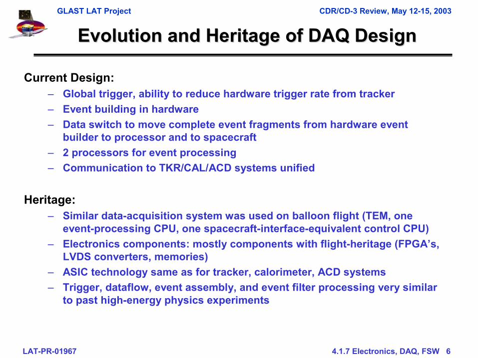
Evolution and Heritage of DAQ DesignEvolution and Heritage of DAQ Design
Current Design:– Global trigger, ability to reduce hardware trigger rate from tracker– Event building in hardware– Data switch to move complete event fragments from hardware event
builder to processor and to spacecraft– 2 processors for event processing– Communication to TKR/CAL/ACD systems unified
Heritage:– Similar data-acquisition system was used on balloon flight (TEM, one
event-processing CPU, one spacecraft-interface-equivalent control CPU)– Electronics components: mostly components with flight-heritage (FPGA’s,
LVDS converters, memories)– ASIC technology same as for tracker, calorimeter, ACD systems– Trigger, dataflow, event assembly, and event filter processing very similar
to past high-energy physics experiments
GLAST LAT Project CDR/CD-3 Review, May 12-15, 2003
LAT-PR-01967 4.1.7 Electronics, DAQ, FSW 7
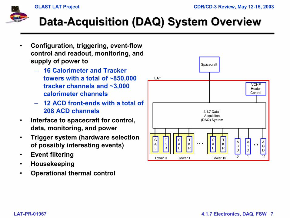
DataData--Acquisition (DAQ) System OverviewAcquisition (DAQ) System Overview
• Configuration, triggering, event-flow control and readout, monitoring, and supply of power to
– 16 Calorimeter and Tracker towers with a total of ~850,000 tracker channels and ~3,000 calorimeter channels
– 12 ACD front-ends with a total of 208 ACD channels
• Interface to spacecraft for control, data, monitoring, and power
• Trigger system (hardware selection of possibly interesting events)
• Event filtering• Housekeeping• Operational thermal control
CAL
TKR
ACD
ACD
ACD
0 1 11Tower 0
CAL
TKR
Tower 1
CAL
TKR
Tower 15
4.1.7 Data-Acquisiton
(DAQ) System
Spacecraft
LAT
VCHPHeaterControl
GLAST LAT Project CDR/CD-3 Review, May 12-15, 2003
LAT-PR-01967 v8 4.1.7 Electronics Overview 8
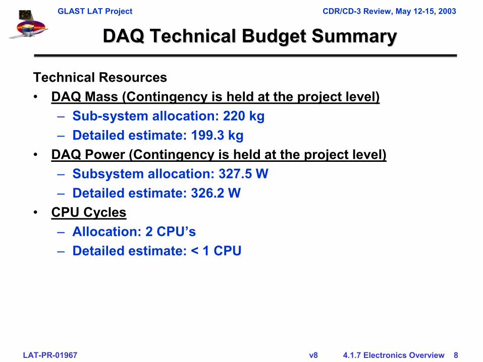
DAQ Technical Budget SummaryDAQ Technical Budget Summary
Technical Resources• DAQ Mass (Contingency is held at the project level)
– Sub-system allocation: 220 kg– Detailed estimate: 199.3 kg
• DAQ Power (Contingency is held at the project level)– Subsystem allocation: 327.5 W– Detailed estimate: 326.2 W
• CPU Cycles– Allocation: 2 CPU’s– Detailed estimate: < 1 CPU
GLAST LAT Project CDR/CD-3 Review, May 12-15, 2003
LAT-PR-01967 v8 4.1.7 Electronics Overview 9
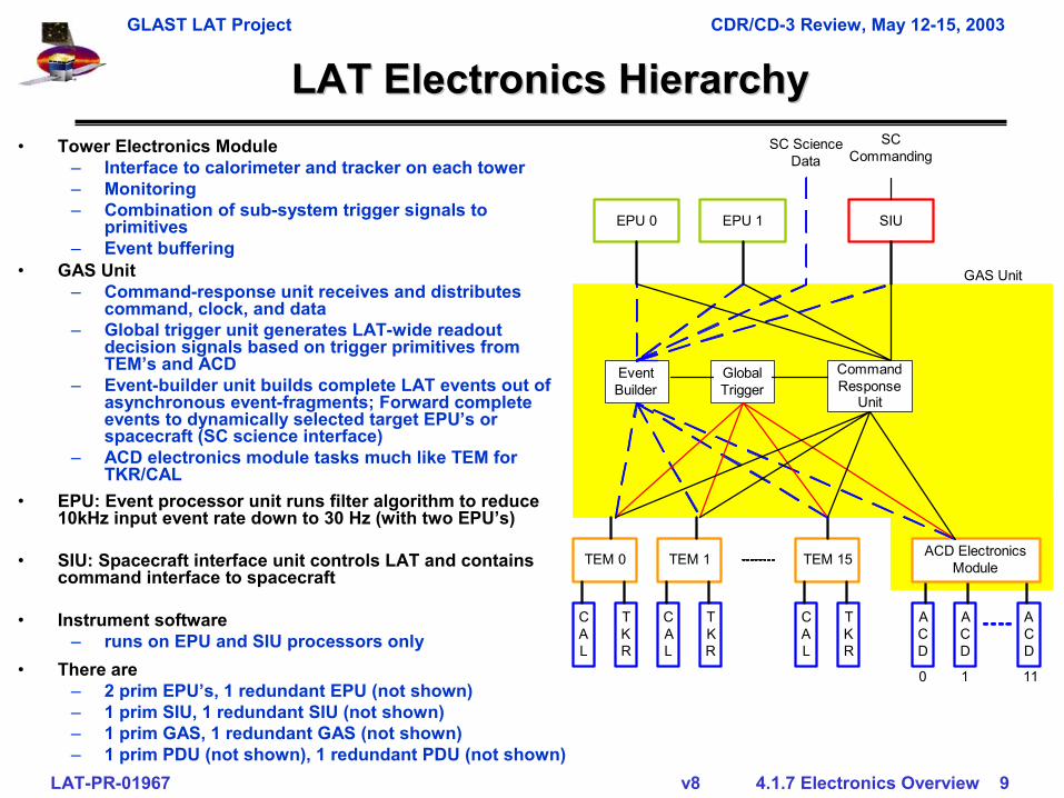
LAT Electronics HierarchyLAT Electronics Hierarchy
SIU
EventBuilder
GlobalTrigger
CommandResponse
Unit
TEM 0
CAL
TKR
TEM 1
CAL
TKR
TEM 15
CAL
TKR
ACD
ACD
ACD
ACD ElectronicsModule
GAS Unit
EPU 0 EPU 1
SCCommanding
SC ScienceData
0 1 11
• Tower Electronics Module– Interface to calorimeter and tracker on each tower– Monitoring– Combination of sub-system trigger signals to
primitives– Event buffering
• There are – 2 prim EPU’s, 1 redundant EPU (not shown)– 1 prim SIU, 1 redundant SIU (not shown)– 1 prim GAS, 1 redundant GAS (not shown)– 1 prim PDU (not shown), 1 redundant PDU (not shown)
• GAS Unit– Command-response unit receives and distributes
command, clock, and data– Global trigger unit generates LAT-wide readout
decision signals based on trigger primitives from TEM’s and ACD
– Event-builder unit builds complete LAT events out of asynchronous event-fragments; Forward complete events to dynamically selected target EPU’s or spacecraft (SC science interface)
– ACD electronics module tasks much like TEM for TKR/CAL
• EPU: Event processor unit runs filter algorithm to reduce 10kHz input event rate down to 30 Hz (with two EPU’s)
• SIU: Spacecraft interface unit controls LAT and contains command interface to spacecraft
• Instrument software– runs on EPU and SIU processors only
GLAST LAT Project CDR/CD-3 Review, May 12-15, 2003
LAT-PR-01967 v8 4.1.7 Electronics Overview 10
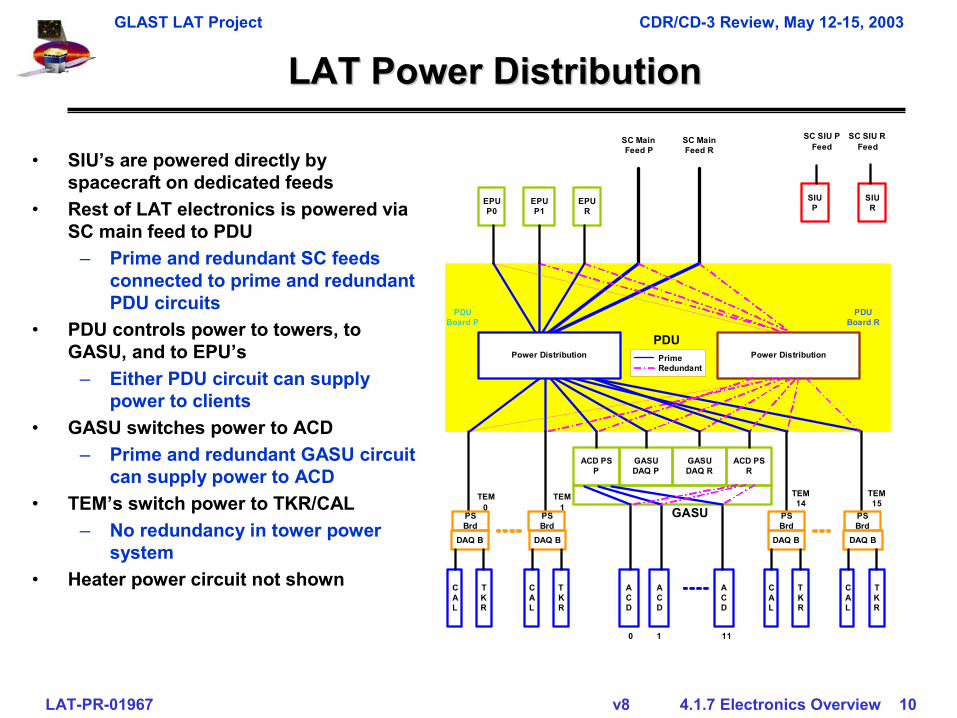
LAT Power DistributionLAT Power Distribution
ACD
ACD
ACD
PDUBoard P
EPUP0
SC MainFeed P
0 1 11
EPUP1
EPUR
SIUR
SIUP
DAQ B
CAL
TKR
Power Distribution
PDUBoard R
DAQ B
CAL
TKR
DAQ B
CAL
TKR
DAQ B
CAL
TKR
SC SIU RFeed
PDUPrimeRedundant
SC SIU PFeed
SC MainFeed R
GASUDAQ P
GASUDAQ R
ACD PSP
ACD PSR
GASUPSBrd
TEM0
PSBrd
PSBrd
PSBrd
TEM1
TEM14
TEM15
Power Distribution
• SIU’s are powered directly by spacecraft on dedicated feeds
• Rest of LAT electronics is powered via SC main feed to PDU
– Prime and redundant SC feeds connected to prime and redundant PDU circuits
• PDU controls power to towers, to GASU, and to EPU’s
– Either PDU circuit can supply power to clients
• GASU switches power to ACD– Prime and redundant GASU circuit
can supply power to ACD• TEM’s switch power to TKR/CAL
– No redundancy in tower power system
• Heater power circuit not shown
GLAST LAT Project CDR/CD-3 Review, May 12-15, 2003
LAT-PR-01967 v8 4.1.7 Electronics Overview 11
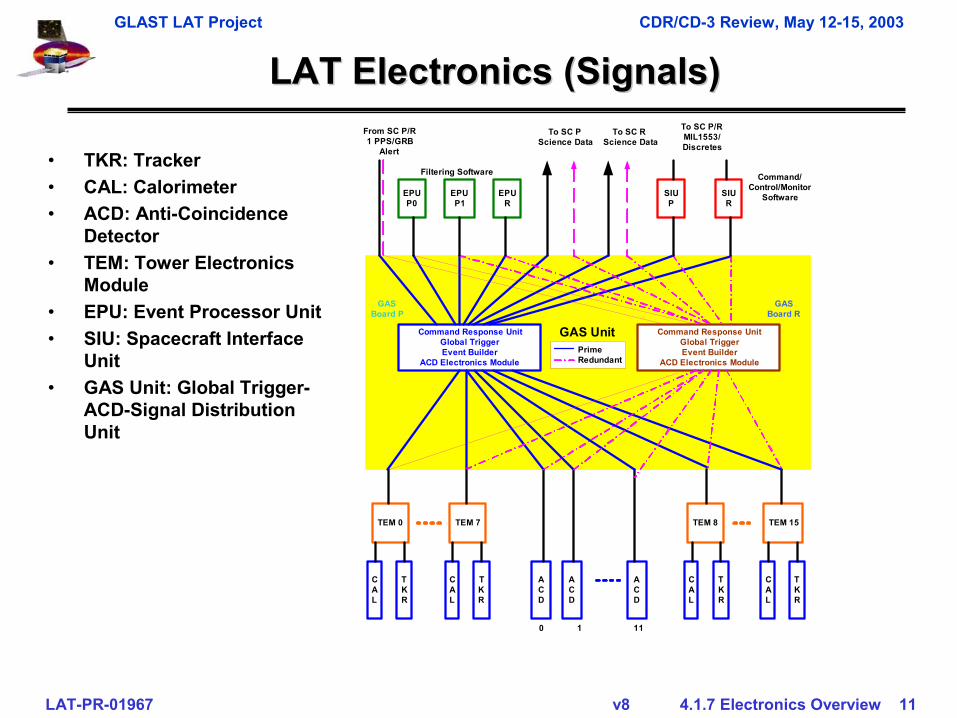
LAT Electronics (Signals)LAT Electronics (Signals)
ACD
ACD
ACD
GASBoard P
EPUP0
To SC PScience Data
0 1 11
EPUP1
EPUR
SIUR
SIUP
TEM 0
CAL
TKR
Command Response UnitGlobal TriggerEvent Builder
ACD Electronics Module
GASBoard R
TEM 15
CAL
TKR
TEM 7
CAL
TKR
TEM 8
CAL
TKR
To SC RScience Data
Filtering Software
Command Response UnitGlobal TriggerEvent Builder
ACD Electronics Module
Command/Control/Monitor
Software
To SC P/RMIL1553/Discretes
From SC P/R1 PPS/GRB
Alert
GAS UnitPrimeRedundant
• TKR: Tracker• CAL: Calorimeter• ACD: Anti-Coincidence
Detector• TEM: Tower Electronics
Module• EPU: Event Processor Unit• SIU: Spacecraft Interface
Unit• GAS Unit: Global Trigger-
ACD-Signal Distribution Unit
GLAST LAT Project CDR/CD-3 Review, May 12-15, 2003
LAT-PR-01967 v8 4.1.7 Electronics Overview 12
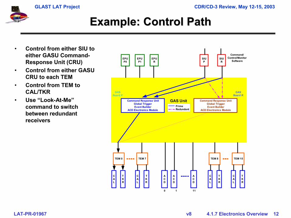
Example: Control PathExample: Control Path
ACD
ACD
ACD
GASBoard P
EPUP0
0 1 11
EPUP1
EPUR
SIUR
SIUP
TEM 0
CAL
TKR
Command Response UnitGlobal TriggerEvent Builder
ACD Electronics Module
GASBoard R
TEM 15
CAL
TKR
TEM 7
CAL
TKR
TEM 8
CAL
TKR
Command Response UnitGlobal TriggerEvent Builder
ACD Electronics Module
Command/Control/Monitor
Software
GAS UnitPrimeRedundant
• Control from either SIU to either GASU Command-Response Unit (CRU)
• Control from either GASU CRU to each TEM
• Control from TEM to CAL/TKR
• Use “Look-At-Me” command to switch between redundant receivers
GLAST LAT Project CDR/CD-3 Review, May 12-15, 2003
LAT-PR-01967 v8 4.1.7 Electronics Overview 13
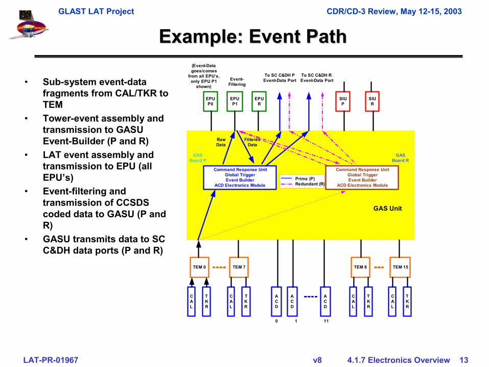
Example: Event PathExample: Event Path
ACD
ACD
ACD
GASBoard P
EPUP0
0 1 11
EPUP1
EPUR
SIUR
SIUP
TEM 0
CAL
TKR
Command Response UnitGlobal TriggerEvent Builder
ACD Electronics Module
GASBoard R
TEM 15
CAL
TKR
TEM 7
CAL
TKR
TEM 8
CAL
TKR
Command Response UnitGlobal TriggerEvent Builder
ACD Electronics Module
To SC C&DH PEvent-Data Port
GAS Unit
Prime (P)Redundant (R)
To SC C&DH REvent-Data PortEvent-
Filtering
(Event-Datagoes/comes
from all EPU’s,only EPU P1
shown)
RawData
FilteredData
• Sub-system event-data fragments from CAL/TKR to TEM
• Tower-event assembly and transmission to GASU Event-Builder (P and R)
• LAT event assembly and transmission to EPU (all EPU’s)
• Event-filtering and transmission of CCSDS coded data to GASU (P and R)
• GASU transmits data to SC C&DH data ports (P and R)
GLAST LAT Project CDR/CD-3 Review, May 12-15, 2003
LAT-PR-01967 v8 4.1.7 Electronics Overview 14
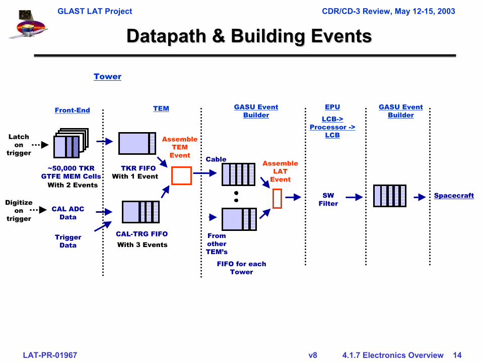
Assemble TEM
Event
DatapathDatapath & Building Events& Building Events
Front-End TEM
CAL-TRG FIFO
CAL ADC Data
With 3 Events
Digitize on
trigger
TKR FIFOWith 1 Event
~50,000 TKR GTFE MEM Cells
With 2 Events
Latch on
trigger
FIFO for each Tower
GASU Event Builder
Cable
Trigger Data
From other TEM’s
Assemble LAT
Event
EPU
LCB-> Processor ->
LCB
SW Filter
Tower
Spacecraft
GASU Event Builder
GLAST LAT Project CDR/CD-3 Review, May 12-15, 2003
LAT-PR-01967 v8 4.1.7 Electronics Overview 15
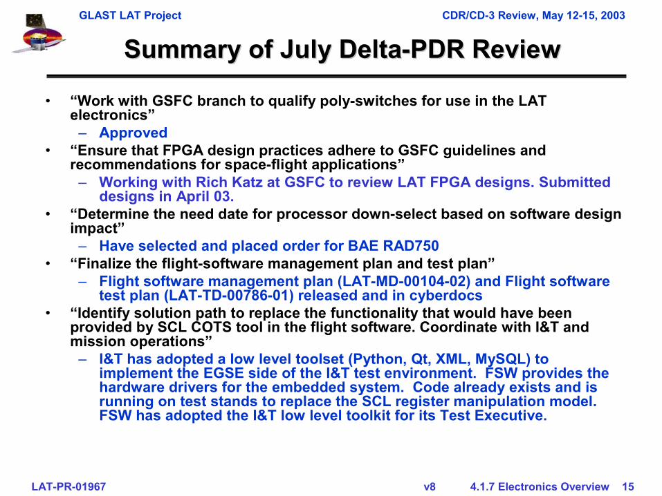
Summary of July DeltaSummary of July Delta--PDR ReviewPDR Review
• “Work with GSFC branch to qualify poly-switches for use in the LAT electronics”
– Approved• “Ensure that FPGA design practices adhere to GSFC guidelines and
recommendations for space-flight applications”– Working with Rich Katz at GSFC to review LAT FPGA designs. Submitted
designs in April 03.• “Determine the need date for processor down-select based on software design
impact”– Have selected and placed order for BAE RAD750
• “Finalize the flight-software management plan and test plan”– Flight software management plan (LAT-MD-00104-02) and Flight software
test plan (LAT-TD-00786-01) released and in cyberdocs• “Identify solution path to replace the functionality that would have been
provided by SCL COTS tool in the flight software. Coordinate with I&T and mission operations”
– I&T has adopted a low level toolset (Python, Qt, XML, MySQL) to implement the EGSE side of the I&T test environment. FSW provides the hardware drivers for the embedded system. Code already exists and is running on test stands to replace the SCL register manipulation model. FSW has adopted the I&T low level toolkit for its Test Executive.
GLAST LAT Project CDR/CD-3 Review, May 12-15, 2003
LAT-PR-01967 v8 4.1.7 Electronics Overview 16
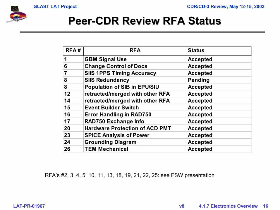
PeerPeer--CDR Review RFA StatusCDR Review RFA Status
RFA’s #2, 3, 4, 5, 10, 11, 13, 18, 19, 21, 22, 25: see FSW presentation
RFA # RFA Status1 GBM Signal Use Accepted6 Change Control of Docs Accepted7 SIIS 1PPS Timing Accuracy Accepted8 SIIS Redundancy Pending8 Population of SIB in EPU/SIU Accepted12 retracted/merged with other RFA Accepted14 retracted/merged with other RFA Accepted15 Event Builder Switch Accepted16 Error Handling in RAD750 Accepted17 RAD750 Exchange Info Accepted20 Hardware Protection of ACD PMT Accepted23 SPICE Analysis of Power Accepted24 Grounding Diagram Accepted26 TEM Mechanical Accepted
GLAST LAT Project CDR/CD-3 Review, May 12-15, 2003
LAT-PR-01967 v8 4.1.7 Electronics Overview 17
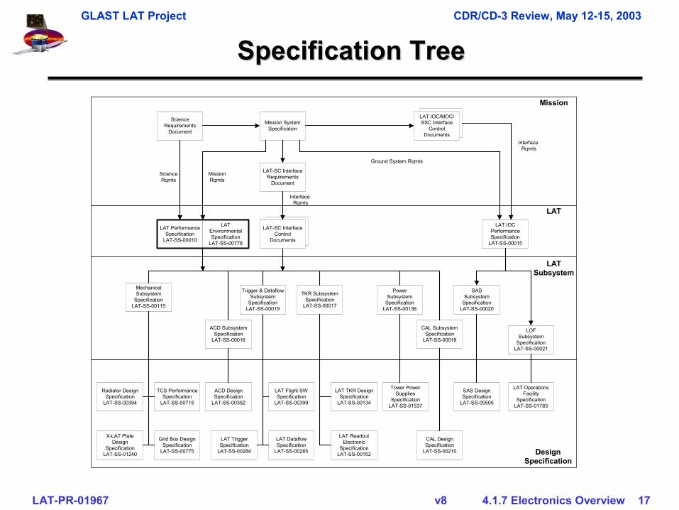
Specification TreeSpecification Tree
Mission SystemSpecification
ScienceRequirements
Document
LAT-SC InterfaceRequirements
Document
LAT PerformanceSpecification
LAT-SS-00010
LATEnvironmentalSpecification
LAT-SS-00778
LAT IOCPerformanceSpecification
LAT-SS-00015
ACD SubsystemSpecification
LAT-SS-00016
TKR SubsystemSpecification
LAT-SS-00017
CAL SubsystemSpecification
LAT-SS-00018
Trigger & DataflowSubsystem
SpecificationLAT-SS-00019
SASSubsystem
SpecificationLAT-SS-00020
LOFSubsystem
SpecificationLAT-SS-00021
PowerSubsystem
SpecificationLAT-SS-00136
MechanicalSubsystem
SpecificationLAT-SS-00115
Mission
LAT
LATSubsystem
ScienceRqmts
MissionRqmts
Ground System Rqmts
Interface Rqmts
Interface Rqmts
TCS PerformanceSpecification
LAT-SS-00715
SAS DesignSpecification
LAT-SS-00505
CAL DesignSpecification
LAT-SS-00210
LAT TriggerSpecification
LAT-SS-00284
LAT TKR DesignSpecification
LAT-SS-00134
LAT OperationsFacility
SpecificationLAT-SS-01783
Tower PowerSupplies
SpecificationLAT-SS-01537
ACD DesignSpecification
LAT-SS-00352
DesignSpecification
LAT DataflowSpecification
LAT-SS-00285
LAT Flight SWSpecification
LAT-SS-00399
LAT ReadoutElectronic
SpecificationLAT-SS-00152
LAT IOC/MOC/SSC Interface
ControlDocuments
Radiator DesignSpecification
LAT-SS-00394
X-LAT PlateDesign
SpecificationLAT-SS-01240
Grid Box DesignSpecification
LAT-SS-00775
LAT-SC InterfaceControl
Documents
GLAST LAT Project CDR/CD-3 Review, May 12-15, 2003
LAT-PR-01967 v8 4.1.7 Electronics Overview 18
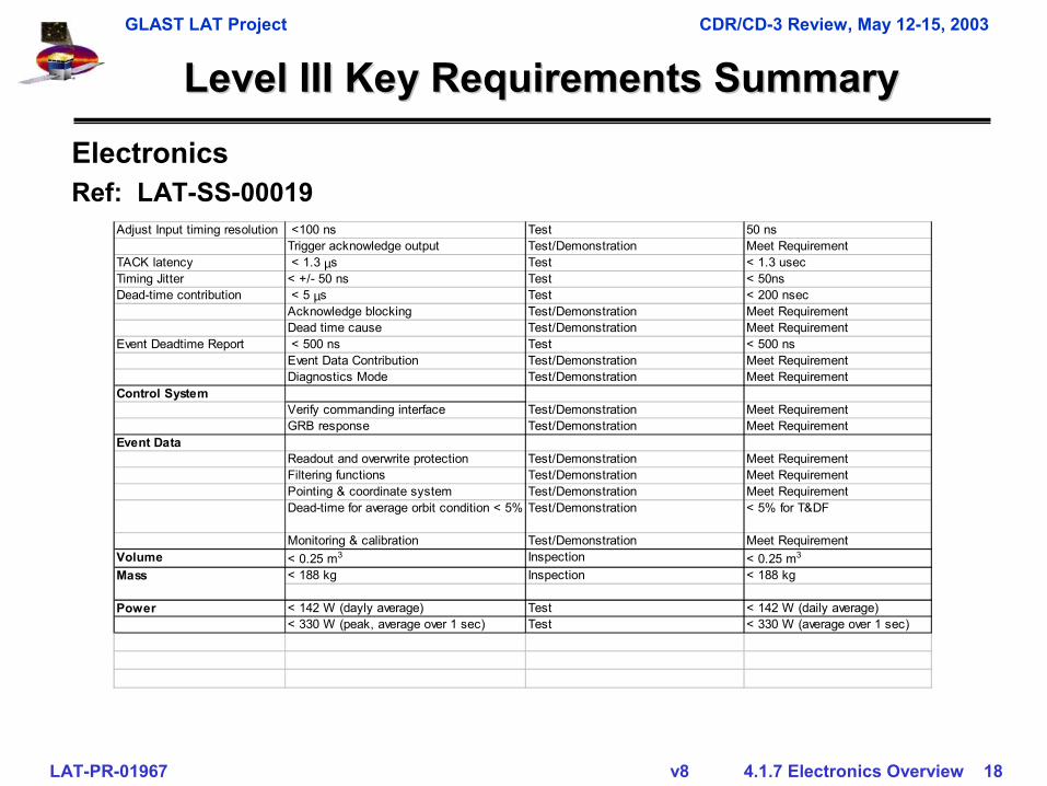
Level III Key Requirements SummaryLevel III Key Requirements Summary
Adjust Input timing resolution <100 ns Test 50 nsTrigger acknowledge output Test/Demonstration Meet Requirement
TACK latency < 1.3 µs Test < 1.3 usecTiming Jitter < +/- 50 ns Test < 50nsDead-time contribution < 5 µs Test < 200 nsec
Acknowledge blocking Test/Demonstration Meet RequirementDead time cause Test/Demonstration Meet Requirement
Event Deadtime Report < 500 ns Test < 500 nsEvent Data Contribution Test/Demonstration Meet RequirementDiagnostics Mode Test/Demonstration Meet Requirement
Control SystemVerify commanding interface Test/Demonstration Meet RequirementGRB response Test/Demonstration Meet Requirement
Event DataReadout and overwrite protection Test/Demonstration Meet RequirementFiltering functions Test/Demonstration Meet RequirementPointing & coordinate system Test/Demonstration Meet RequirementDead-time for average orbit condition < 5% Test/Demonstration < 5% for T&DF
Monitoring & calibration Test/Demonstration Meet RequirementVolume < 0.25 m3 Inspection < 0.25 m3
< 188 kg Inspection < 188 kg
Power < 142 W (dayly average) Test < 142 W (daily average)< 330 W (peak, average over 1 sec) Test < 330 W (average over 1 sec)
Mass
ElectronicsRef: LAT-SS-00019
GLAST LAT Project CDR/CD-3 Review, May 12-15, 2003
LAT-PR-01967 v8 4.1.7 Electronics Overview 19
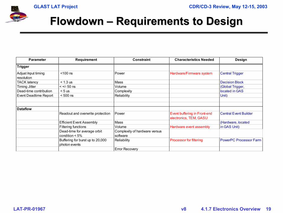
FlowdownFlowdown –– Requirements to DesignRequirements to Design
Parameter Requirement Constraint Characteristics Needed Design
Trigger
Adjust Input timing resolution
<100 ns Power Hardware/Firmware system Central Trigger
TACK latency < 1.3 us Mass Decision BlockTiming Jitter < +/- 50 ns Volume (Global Trigger,Dead-time contribution < 5 us Complexity located in GASEvent Deadtime Report < 500 ns Reliability Unit)
DataflowReadout and overwrite protection Power Event buffering in Front-end
electronics, TEM, GASUCentral Event Builder
Efficient Event Assembly Mass (Hardware, locatedFiltering functions Volume Hardware event assembly in GAS Unit)Dead-time for average orbit condition < 5%
Complexity of hardware versus software
Buffering for burst up to 20,000 photon events
Reliability Processor for filtering PowerPC Processor Farm
Error Recovery
GLAST LAT Project CDR/CD-3 Review, May 12-15, 2003
LAT-PR-01967 v8 4.1.7 Electronics Overview 20
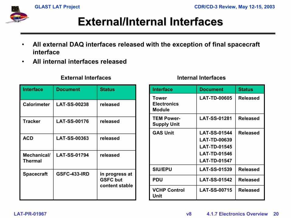
External/Internal InterfacesExternal/Internal Interfaces
releasedLAT-SS-01794Mechanical/Thermal
in progress at GSFC but content stable
GSFC-433-IRDSpacecraft
releasedLAT-SS-00363ACD
releasedLAT-SS-00176Tracker
releasedLAT-SS-00238Calorimeter
StatusDocument Interface
• All external DAQ interfaces released with the exception of final spacecraft interface
• All internal interfaces released
ReleasedLAT-SS-01542PDU
ReleasedLAT-SS-01539SIU/EPU
ReleasedLAT-SS-00715VCHP Control Unit
ReleasedLAT-SS-01544LAT-TD-00639LAT-TD-01545LAT-TD-01546LAT-TD-01547
GAS Unit
ReleasedLAT-SS-01281TEM Power-Supply Unit
ReleasedLAT-TD-00605Tower Electronics Module
StatusDocument Interface
External Interfaces Internal Interfaces
GLAST LAT Project CDR/CD-3 Review, May 12-15, 2003
LAT-PR-01967 v8 4.1.7 Electronics Overview 21
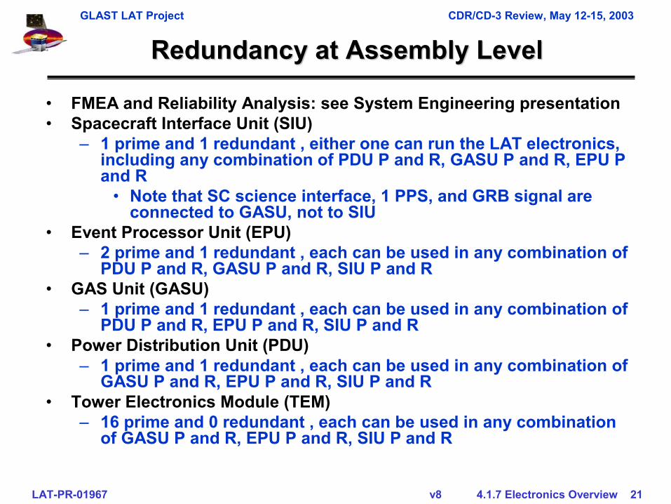
Redundancy at Assembly LevelRedundancy at Assembly Level
• FMEA and Reliability Analysis: see System Engineering presentation• Spacecraft Interface Unit (SIU)
– 1 prime and 1 redundant , either one can run the LAT electronics, including any combination of PDU P and R, GASU P and R, EPU P and R
• Note that SC science interface, 1 PPS, and GRB signal are connected to GASU, not to SIU
• Event Processor Unit (EPU)– 2 prime and 1 redundant , each can be used in any combination of
PDU P and R, GASU P and R, SIU P and R• GAS Unit (GASU)
– 1 prime and 1 redundant , each can be used in any combination ofPDU P and R, EPU P and R, SIU P and R
• Power Distribution Unit (PDU)– 1 prime and 1 redundant , each can be used in any combination of
GASU P and R, EPU P and R, SIU P and R• Tower Electronics Module (TEM)
– 16 prime and 0 redundant , each can be used in any combination of GASU P and R, EPU P and R, SIU P and R
GLAST LAT Project CDR/CD-3 Review, May 12-15, 2003
LAT-PR-01967 v8 4.1.7 Electronics Overview 22
Components & AssembliesComponents & Assemblies
• Design• Mechanical• Thermal
• As an example, TEM assembly is presented in more detail
GLAST LAT Project CDR/CD-3 Review, May 12-15, 2003
LAT-PR-01967 v8 4.1.7 Electronics Overview 23
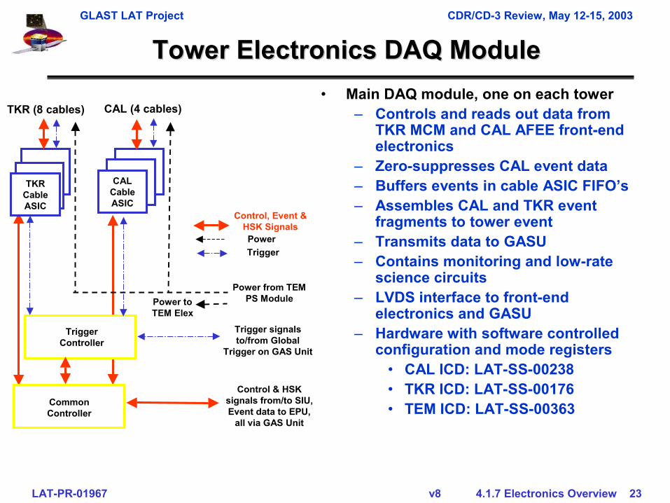
Tower Electronics DAQ ModuleTower Electronics DAQ Module• Main DAQ module, one on each tower
– Controls and reads out data from TKR MCM and CAL AFEE front-end electronics
– Zero-suppresses CAL event data– Buffers events in cable ASIC FIFO’s– Assembles CAL and TKR event
fragments to tower event – Transmits data to GASU– Contains monitoring and low-rate
science circuits– LVDS interface to front-end
electronics and GASU– Hardware with software controlled
configuration and mode registers• CAL ICD: LAT-SS-00238• TKR ICD: LAT-SS-00176• TEM ICD: LAT-SS-00363
Trigger Controller
Control, Event & HSK SignalsPower
Power from TEM PS Module
TKR (8 cables)
Trigger
TKR Cable ASIC
CAL Cable ASIC
CAL (4 cables)
Common Controller
Power to TEM Elex
Trigger signals to/from Global
Trigger on GAS Unit
Control & HSK signals from/to SIU, Event data to EPU,
all via GAS Unit
GLAST LAT Project CDR/CD-3 Review, May 12-15, 2003
LAT-PR-01967 v8 4.1.7 Electronics Overview 24
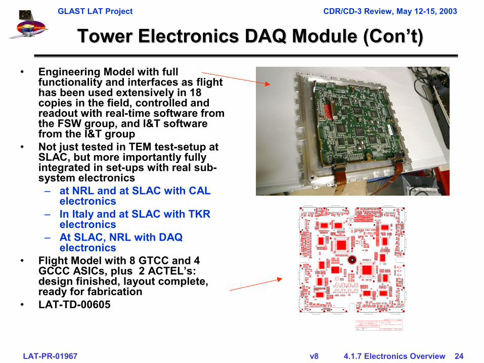
Tower Electronics DAQ Module (Tower Electronics DAQ Module (Con’tCon’t))• Engineering Model with full
functionality and interfaces as flight has been used extensively in 18 copies in the field, controlled and readout with real-time software from the FSW group, and I&T software from the I&T group
• Not just tested in TEM test-setup at SLAC, but more importantly fully integrated in set-ups with real sub-system electronics
– at NRL and at SLAC with CAL electronics
– In Italy and at SLAC with TKR electronics
– At SLAC, NRL with DAQ electronics
• Flight Model with 8 GTCC and 4 GCCC ASICs, plus 2 ACTEL’s: design finished, layout complete, ready for fabrication
• LAT-TD-00605
GLAST LAT Project CDR/CD-3 Review, May 12-15, 2003
LAT-PR-01967 v8 4.1.7 Electronics Overview 25
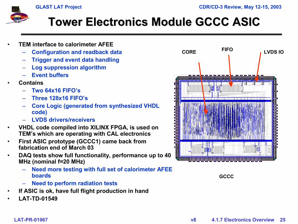
Tower Electronics Module GCCC ASICTower Electronics Module GCCC ASIC• TEM interface to calorimeter AFEE
– Configuration and readback data– Trigger and event data handling– Log suppression algorithm– Event buffers
• Contains – Two 64x16 FIFO’s– Three 128x16 FIFO’s– Core Logic (generated from synthesized VHDL
code)– LVDS drivers/receivers
• VHDL code compiled into XILINX FPGA, is used on TEM’s which are operating with CAL electronics
• First ASIC prototype (GCCC1) came back from fabrication end of March 03
• DAQ tests show full functionality, performance up to 40 MHz (nominal f=20 MHz)
– Need more testing with full set of calorimeter AFEE boards
– Need to perform radiation tests• If ASIC is ok, have full flight production in hand• LAT-TD-01549
LVDS IOCORE FIFO
GCCC
GLAST LAT Project CDR/CD-3 Review, May 12-15, 2003
LAT-PR-01967 v8 4.1.7 Electronics Overview 26
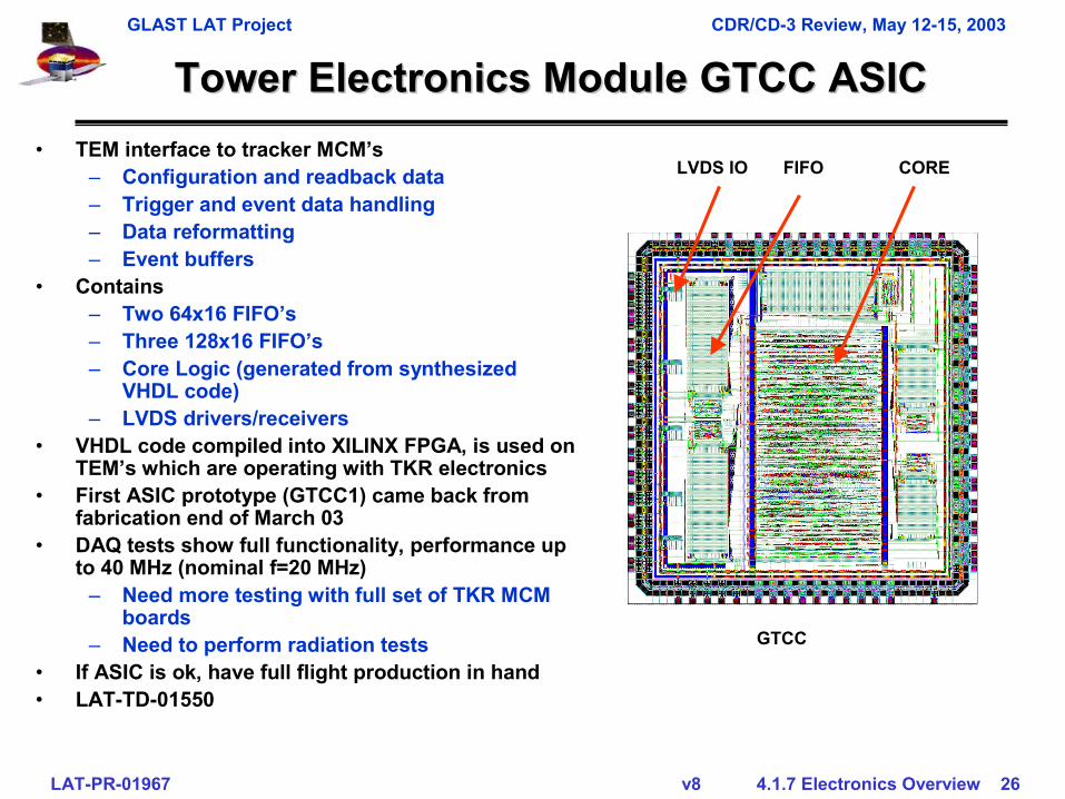
Tower Electronics Module GTCC ASICTower Electronics Module GTCC ASIC• TEM interface to tracker MCM’s
– Configuration and readback data– Trigger and event data handling– Data reformatting– Event buffers
• Contains – Two 64x16 FIFO’s– Three 128x16 FIFO’s– Core Logic (generated from synthesized
VHDL code)– LVDS drivers/receivers
• VHDL code compiled into XILINX FPGA, is used on TEM’s which are operating with TKR electronics
• First ASIC prototype (GTCC1) came back from fabrication end of March 03
• DAQ tests show full functionality, performance up to 40 MHz (nominal f=20 MHz)
– Need more testing with full set of TKR MCM boards
– Need to perform radiation tests• If ASIC is ok, have full flight production in hand• LAT-TD-01550
LVDS IO COREFIFO
GTCC
GLAST LAT Project CDR/CD-3 Review, May 12-15, 2003
LAT-PR-01967 v8 4.1.7 Electronics Overview 27
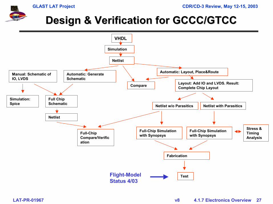
Design & Verification for GCCC/GTCCDesign & Verification for GCCC/GTCCVHDL
Simulation
Netlist
Automatic: Layout, Place&Route
Compare Layout: Add IO and LVDS. Result: Complete Chip Layout
Automatic: Generate Schematic
Manual: Schematic of IO, LVDS
Simulation: Spice
Full Chip Schematic
Netlist
Netlist w/o Parasitics Netlist with Parasitics
Full-Chip Simulation with Synopsys
Full-Chip Simulation with SynopsysFull-Chip
Compare/Verification
Fabrication
Test
Stress & Timing Analysis
Flight-Model Status 4/03
GLAST LAT Project CDR/CD-3 Review, May 12-15, 2003
LAT-PR-01967 v8 4.1.7 Electronics Overview 28
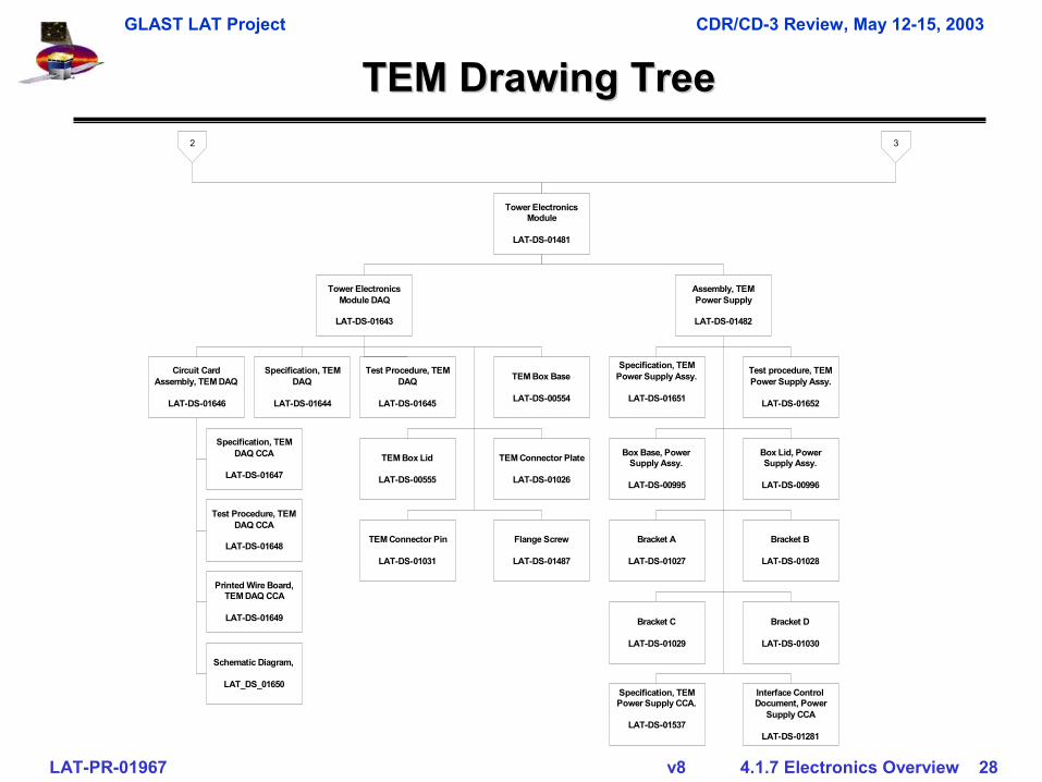
TEM Drawing TreeTEM Drawing Tree
Tower ElectronicsModule DAQ
LAT-DS-01643
Tower ElectronicsModule
LAT-DS-01481
Circuit CardAssembly, TEM DAQ
LAT-DS-01646
Specification, TEMDAQ
LAT-DS-01644
Test Procedure, TEMDAQ
LAT-DS-01645
TEM Box Base
LAT-DS-00554
Specification, TEMDAQ CCA
LAT-DS-01647
Test Procedure, TEMDAQ CCA
LAT-DS-01648
Printed Wire Board,TEM DAQ CCA
LAT-DS-01649
Schematic Diagram,
LAT_DS_01650
TEM Box Lid
LAT-DS-00555
TEM Connector Plate
LAT-DS-01026
TEM Connector Pin
LAT-DS-01031
Flange Screw
LAT-DS-01487
Assembly, TEMPower Supply
LAT-DS-01482
Specification, TEMPower Supply Assy.
LAT-DS-01651
Box Base, PowerSupply Assy.
LAT-DS-00995
Bracket A
LAT-DS-01027
Bracket C
LAT-DS-01029
Specification, TEMPower Supply CCA.
LAT-DS-01537
Test procedure, TEMPower Supply Assy.
LAT-DS-01652
Box Lid, PowerSupply Assy.
LAT-DS-00996
Bracket B
LAT-DS-01028
Bracket D
LAT-DS-01030
Interface ControlDocument, Power
Supply CCA
LAT-DS-01281
2 3
GLAST LAT Project CDR/CD-3 Review, May 12-15, 2003
LAT-PR-01967 v8 4.1.7 Electronics Overview 29
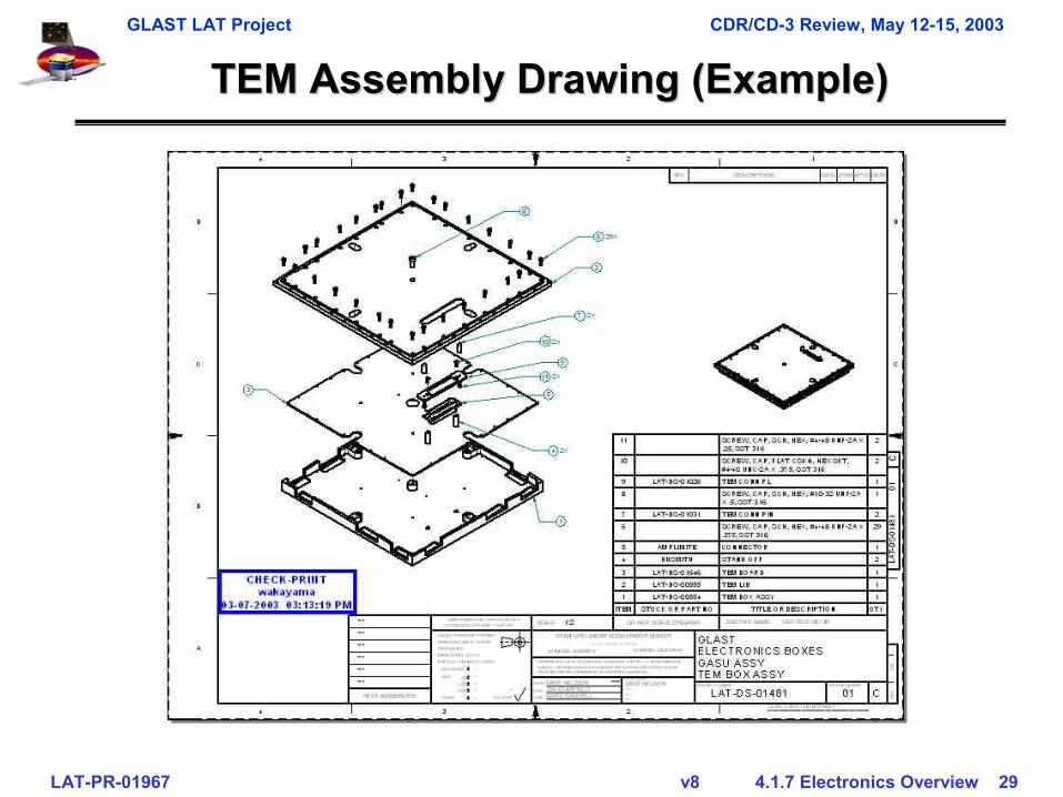
TEM Assembly Drawing (Example)TEM Assembly Drawing (Example)
GLAST LAT Project CDR/CD-3 Review, May 12-15, 2003
LAT-PR-01967 v8 4.1.7 Electronics Overview 30
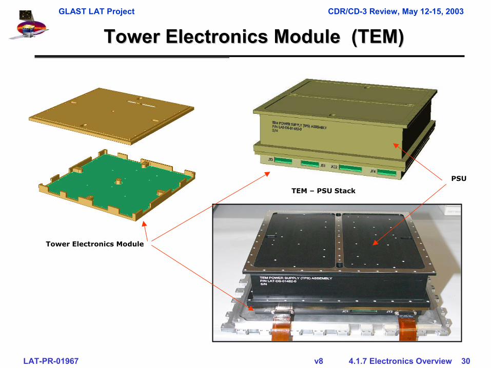
Tower Electronics Module (TEM)Tower Electronics Module (TEM)
TEM – PSU Stack
Tower Electronics Module
PSU
GLAST LAT Project CDR/CD-3 Review, May 12-15, 2003
LAT-PR-01967 v8 4.1.7 Electronics Overview 31
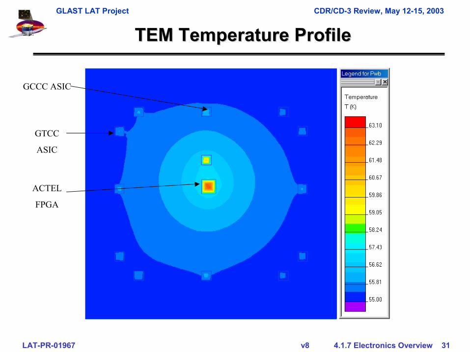
TEM Temperature ProfileTEM Temperature Profile
GCCC ASIC
GTCC
ASIC
ACTEL
FPGA
GLAST LAT Project CDR/CD-3 Review, May 12-15, 2003
LAT-PR-01967 v8 4.1.7 Electronics Overview 32
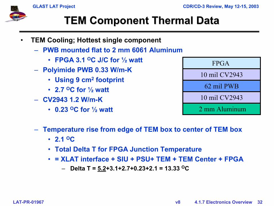
TEM Component Thermal DataTEM Component Thermal Data• TEM Cooling; Hottest single component
– PWB mounted flat to 2 mm 6061 Aluminum• FPGA 3.1 OC J/C for ½ watt
– Polyimide PWB 0.33 W/m-K• Using 9 cm2 footprint• 2.7 OC for ½ watt
– CV2943 1.2 W/m-K• 0.23 OC for ½ watt
– Temperature rise from edge of TEM box to center of TEM box• 2.1 OC • Total Delta T for FPGA Junction Temperature• = XLAT interface + SIU + PSU+ TEM + TEM Center + FPGA
– Delta T = 5.2+3.1+2.7+0.23+2.1 = 13.33 OC
10 mil CV2943
62 mil PWB
10 mil CV2943
2 mm Aluminum
FPGA
GLAST LAT Project CDR/CD-3 Review, May 12-15, 2003
LAT-PR-01967 v8 4.1.7 Electronics Overview 33
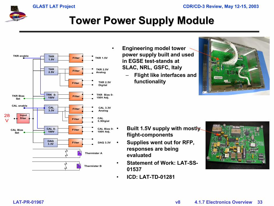
Tower Power Supply ModuleTower Power Supply Module
TKR2.5V
TRK 0-150V
Filter
Filter
Filter
CAL3.3V Filter
CAL 0-100V
Filter
Filter
TKR1.5V Filter
DAQ3.3V Filter
TKR enableTKR 1.5V
DAQ 3.3V
CAL Bias 0-100V Adj.
CAL3.3Digial
TKR Bias 0-150V Adj.
28V
TKR BiasSet
CAL BiasSet
A Thermister A
B Thermister B
CAL enable
Inputfilter
TKR 2.5VAnalog
TKR 2.5VDigital
CAL 3.3VAnalog
• Engineering model tower power supply built and used in EGSE test-stands at SLAC, NRL, GSFC, Italy
– Flight like interfaces and functionality
• Built 1.5V supply with mostly flight-components
• Supplies went out for RFP, responses are being evaluated
• Statement of Work: LAT-SS-01537
• ICD: LAT-TD-01281
GLAST LAT Project CDR/CD-3 Review, May 12-15, 2003
LAT-PR-01967 v8 4.1.7 Electronics Overview 34
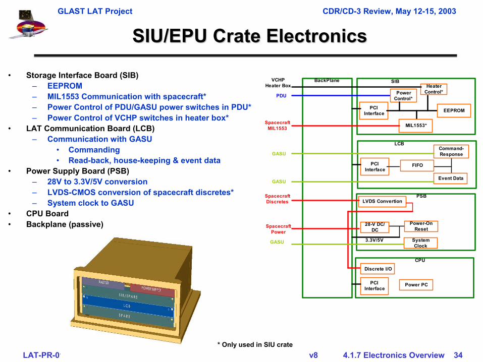
SIU/EPU Crate ElectronicsSIU/EPU Crate Electronics
• Storage Interface Board (SIB)– EEPROM– MIL1553 Communication with spacecraft*– Power Control of PDU/GASU power switches in PDU*– Power Control of VCHP switches in heater box*
• LAT Communication Board (LCB)– Communication with GASU
• Commanding• Read-back, house-keeping & event data
• Power Supply Board (PSB)– 28V to 3.3V/5V conversion– LVDS-CMOS conversion of spacecraft discretes*– System clock to GASU
• CPU Board• Backplane (passive)
PCIInterface
SIB
MIL1553*
PowerControl*
EEPROM
BackPlaneHeater
Control*
PCIInterface
Event Data
Command-Response
FIFO
LCB
28-V DC/DC
Power-OnReset
LVDS ConvertionPSB
3.3V/5V
CPU
PCIInterface
Power PC
Discrete I/O
VCHPHeater Box
PDU
SpacecraftMIL1553
GASU
SpacecraftPower
GASU
SpacecraftDiscretes
SystemClock
GASU
* Only used in SIU crate
GLAST LAT Project CDR/CD-3 Review, May 12-15, 2003
LAT-PR-01967 v8 4.1.7 Electronics Overview 35
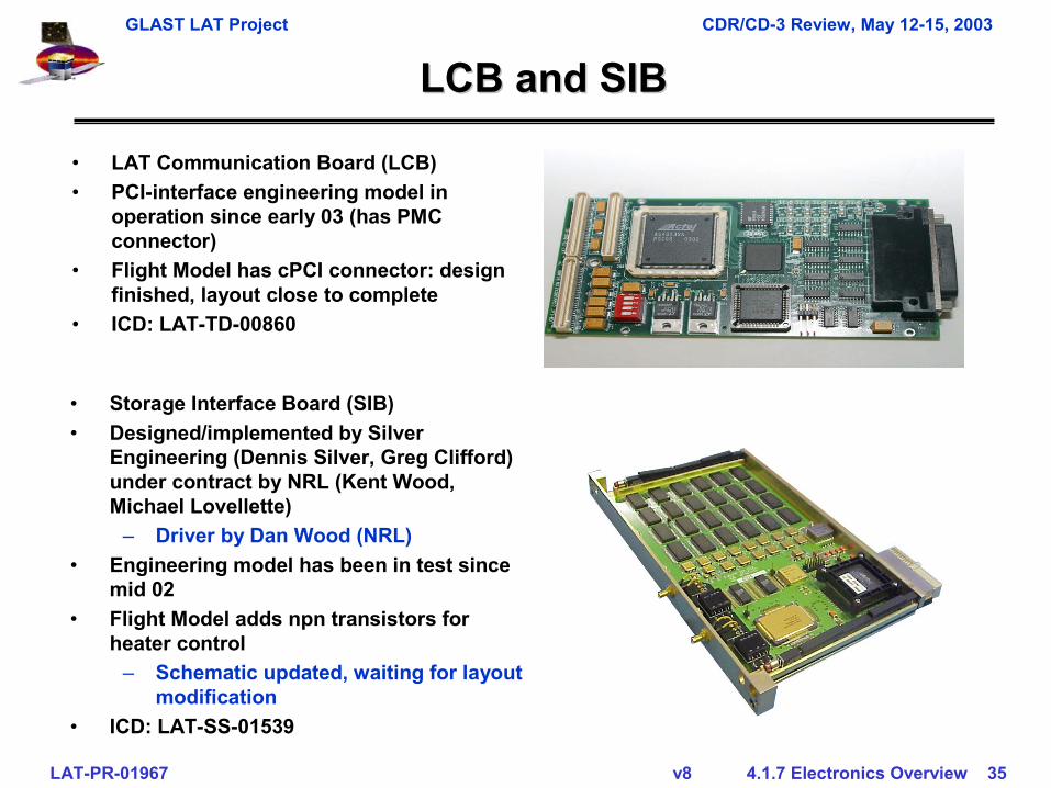
LCB and SIBLCB and SIB
• LAT Communication Board (LCB) • PCI-interface engineering model in
operation since early 03 (has PMC connector)
• Flight Model has cPCI connector: design finished, layout close to complete
• ICD: LAT-TD-00860
• Storage Interface Board (SIB) • Designed/implemented by Silver
Engineering (Dennis Silver, Greg Clifford) under contract by NRL (Kent Wood, Michael Lovellette)
– Driver by Dan Wood (NRL)• Engineering model has been in test since
mid 02• Flight Model adds npn transistors for
heater control– Schematic updated, waiting for layout
modification• ICD: LAT-SS-01539
GLAST LAT Project CDR/CD-3 Review, May 12-15, 2003
LAT-PR-01967 v8 4.1.7 Electronics Overview 36
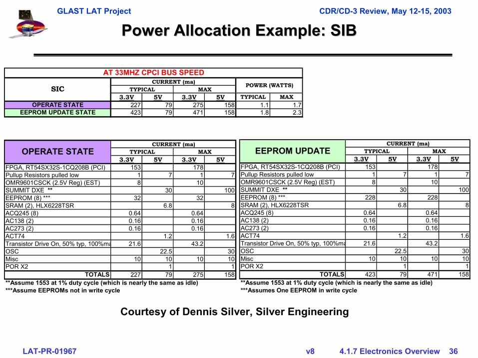
Power Allocation Example: SIBPower Allocation Example: SIB
3.3V 5V 3.3V 5V TYPICAL MAXOPERATE STATE 227 79 275 158 1.1 1.7
EEPROM UPDATE STATE 423 79 471 158 1.8 2.3
3.3V 5V 3.3V 5VFPGA, RT54SX32S-1CQ208B (PCI) 153 178Pullup Resistors pulled low 1 7 1 7OMR9601CSCK (2.5V Reg) (EST) 8 10SUMMIT DXE ** 30 100EEPROM (8) *** 32 32SRAM (2), HLX6228TSR 6.8 8ACQ245 (8) 0.64 0.64AC138 (2) 0.16 0.16AC273 (2) 0.16 0.16ACT74 1.2 1.6Transistor Drive On, 50% typ, 100%ma 21.6 43.2OSC 22.5 30Misc 10 10 10 10POR X2 1 1
TOTALS 227 79 275 158**Assume 1553 at 1% duty cycle (which is nearly the same as idle)***Assume EEPROMs not in write cycle
OPERATE STATECURRENT (ma)
TYPICAL MAX
TYPICAL MAX
AT 33MHZ CPCI BUS SPEED
SICCURRENT (ma) POWER (WATTS)
3.3V 5V 3.3V 5VFPGA, RT54SX32S-1CQ208B (PCI) 153 178Pullup Resistors pulled low 1 7 1 7OMR9601CSCK (2.5V Reg) (EST) 8 10SUMMIT DXE ** 30 100EEPROM (8) *** 228 228SRAM (2), HLX6228TSR 6.8 8ACQ245 (8) 0.64 0.64AC138 (2) 0.16 0.16AC273 (2) 0.16 0.16ACT74 1.2 1.6Transistor Drive On, 50% typ, 100%ma 21.6 43.2OSC 22.5 30Misc 10 10 10 10POR X2 1 1
TOTALS 423 79 471 158**Assume 1553 at 1% duty cycle (which is nearly the same as idle)***Assumes One EEPROM in write cycle
EEPROM UPDATECURRENT (ma)
TYPICAL MAX
Courtesy of Dennis Silver, Silver Engineering
GLAST LAT Project CDR/CD-3 Review, May 12-15, 2003
LAT-PR-01967 v8 4.1.7 Electronics Overview 37
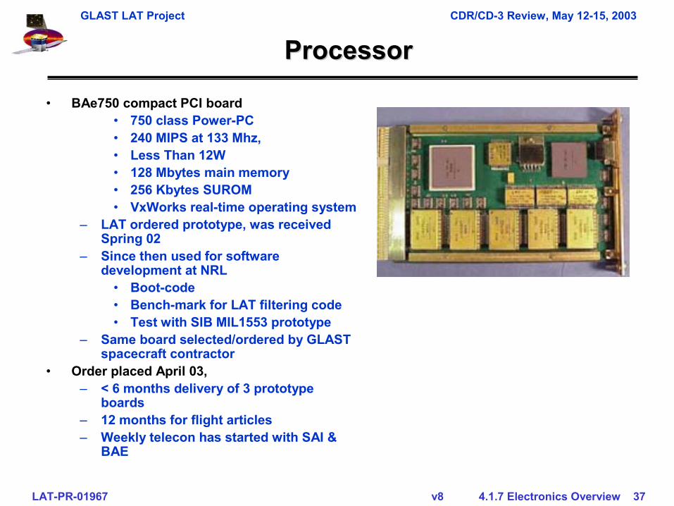
ProcessorProcessor
• BAe750 compact PCI board• 750 class Power-PC• 240 MIPS at 133 Mhz, • Less Than 12W• 128 Mbytes main memory• 256 Kbytes SUROM • VxWorks real-time operating system
– LAT ordered prototype, was received Spring 02
– Since then used for software development at NRL
• Boot-code• Bench-mark for LAT filtering code• Test with SIB MIL1553 prototype
– Same board selected/ordered by GLAST spacecraft contractor
• Order placed April 03, – < 6 months delivery of 3 prototype
boards– 12 months for flight articles– Weekly telecon has started with SAI &
BAE
GLAST LAT Project CDR/CD-3 Review, May 12-15, 2003
LAT-PR-01967 v8 4.1.7 Electronics Overview 38
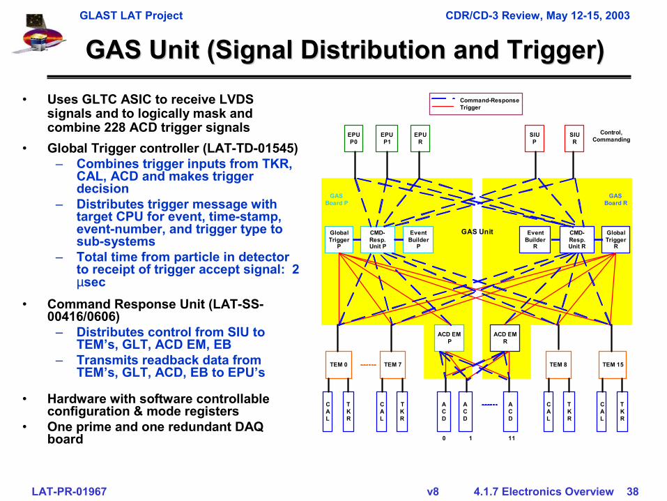
GAS Unit (Signal Distribution and Trigger)GAS Unit (Signal Distribution and Trigger)
EventBuilder
P
GlobalTrigger
P
CMD-Resp.Unit P
ACD
ACD
ACD
ACD EMP
GASBoard P
EPUP0
0 1 11
EPUP1
EPUR
SIUR
SIUP
ACD EMR
TEM 0
CAL
TKR
EventBuilder
R
GlobalTrigger
R
CMD-Resp.Unit R
GASBoard R
TEM 15
CAL
TKR
TEM 7
CAL
TKR
TEM 8
CAL
TKR
GAS Unit
Control,Commanding
Command-ResponseTrigger
• Uses GLTC ASIC to receive LVDS signals and to logically mask and combine 228 ACD trigger signals
• Hardware with software controllable configuration & mode registers
• One prime and one redundant DAQ board
• Global Trigger controller (LAT-TD-01545)– Combines trigger inputs from TKR,
CAL, ACD and makes trigger decision
– Distributes trigger message with target CPU for event, time-stamp, event-number, and trigger type to sub-systems
– Total time from particle in detector to receipt of trigger accept signal: 2 µsec
• Command Response Unit (LAT-SS-00416/0606)
– Distributes control from SIU to TEM’s, GLT, ACD EM, EB
– Transmits readback data from TEM’s, GLT, ACD, EB to EPU’s
GLAST LAT Project CDR/CD-3 Review, May 12-15, 2003
LAT-PR-01967 v8 4.1.7 Electronics Overview 39
GAS Unit (ACD EM & Event Data)GAS Unit (ACD EM & Event Data)
EventBuilder
P
GlobalTrigger
P
CMD-Resp.Unit P
ACD
ACD
ACD
ACD EMP
GASBoard P
EPUP0
To SC PScience
Data
0 1 11
EPUP1
EPUR
SIUR
SIUP
ACD EMR
TEM 0
CAL
TKR
EventBuilder
R
GlobalTrigger
R
CMD-Resp.Unit R
GASBoard R
TEM 15
CAL
TKR
TEM 7
CAL
TKR
TEM 8
CAL
TKR
GAS Unit
To SC RScience
Data
Filtering Software
PrimeRedundant
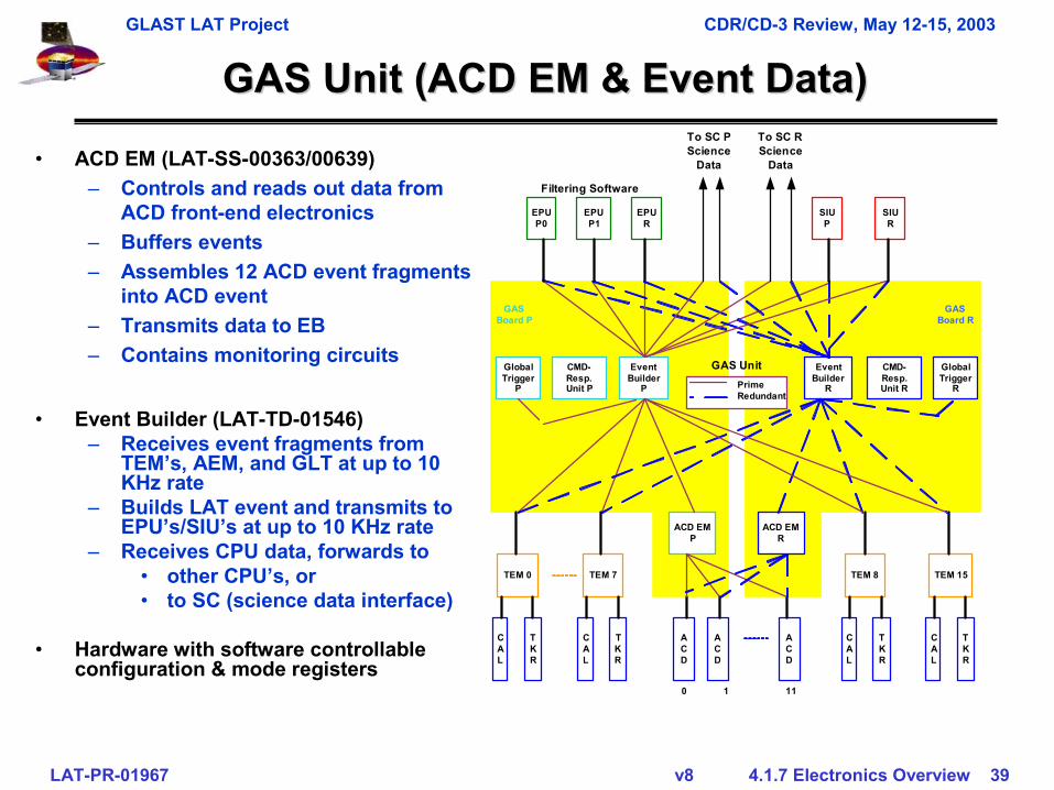
• ACD EM (LAT-SS-00363/00639)– Controls and reads out data from
ACD front-end electronics– Buffers events– Assembles 12 ACD event fragments
into ACD event – Transmits data to EB– Contains monitoring circuits
• Event Builder (LAT-TD-01546)– Receives event fragments from
TEM’s, AEM, and GLT at up to 10 KHz rate
– Builds LAT event and transmits to EPU’s/SIU’s at up to 10 KHz rate
– Receives CPU data, forwards to• other CPU’s, or • to SC (science data interface)
• Hardware with software controllable configuration & mode registers
GLAST LAT Project CDR/CD-3 Review, May 12-15, 2003
LAT-PR-01967 v8 4.1.7 Electronics Overview 40
GAS Unit & GLTC ASICGAS Unit & GLTC ASIC
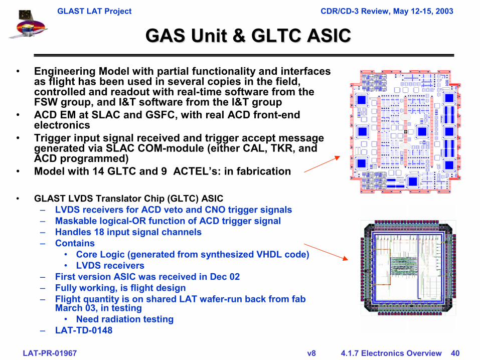
• GLAST LVDS Translator Chip (GLTC) ASIC– LVDS receivers for ACD veto and CNO trigger signals– Maskable logical-OR function of ACD trigger signal– Handles 18 input signal channels– Contains
• Core Logic (generated from synthesized VHDL code)• LVDS receivers
– First version ASIC was received in Dec 02– Fully working, is flight design– Flight quantity is on shared LAT wafer-run back from fab
March 03, in testing• Need radiation testing
– LAT-TD-0148
• Engineering Model with partial functionality and interfaces as flight has been used in several copies in the field, controlled and readout with real-time software from the FSW group, and I&T software from the I&T group
• ACD EM at SLAC and GSFC, with real ACD front-end electronics
• Trigger input signal received and trigger accept message generated via SLAC COM-module (either CAL, TKR, and ACD programmed)
• Model with 14 GLTC and 9 ACTEL’s: in fabrication
GLAST LAT Project CDR/CD-3 Review, May 12-15, 2003
LAT-PR-01967 v8 4.1.7 Electronics Overview 41
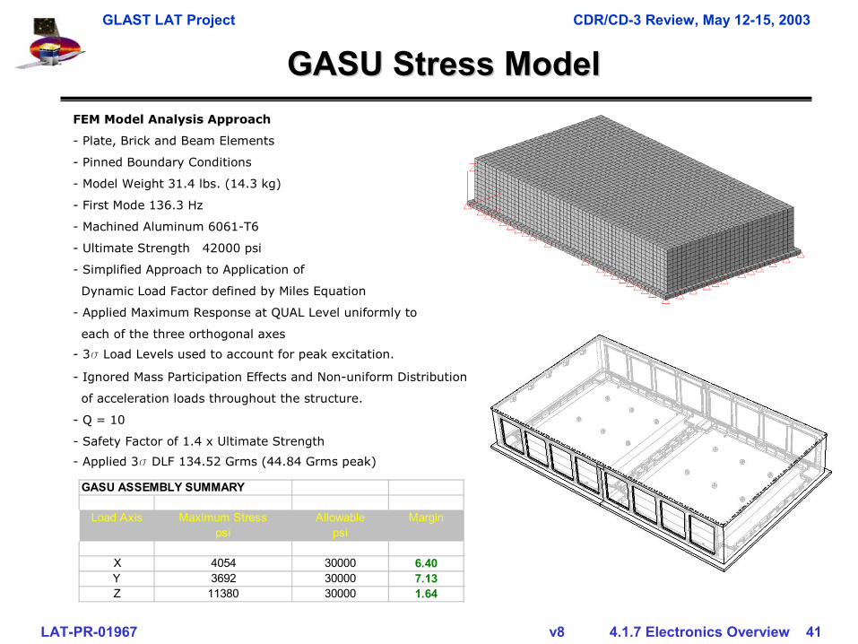
FEM Model Analysis Approach
- Plate, Brick and Beam Elements
- Pinned Boundary Conditions
- Model Weight 31.4 lbs. (14.3 kg)
- First Mode 136.3 Hz
- Machined Aluminum 6061-T6
- Ultimate Strength 42000 psi
- Simplified Approach to Application of
Dynamic Load Factor defined by Miles Equation
- Applied Maximum Response at QUAL Level uniformly to
each of the three orthogonal axes
- 3s Load Levels used to account for peak excitation.
- Ignored Mass Participation Effects and Non-uniform Distribution
of acceleration loads throughout the structure.
- Q = 10
- Safety Factor of 1.4 x Ultimate Strength
- Applied 3s DLF 134.52 Grms (44.84 Grms peak)
GASU ASSEMBLY SUMMARY
Load Axis Maximum Stress Allowable Marginpsi psi
X 4054 30000 6.40Y 3692 30000 7.13Z 11380 30000 1.64
GASU Stress ModelGASU Stress Model
GLAST LAT Project CDR/CD-3 Review, May 12-15, 2003
LAT-PR-01967 v8 4.1.7 Electronics Overview 42
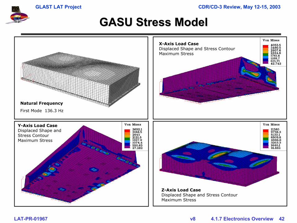
X-Axis Load CaseDisplaced Shape and Stress ContourMaximum Stress
Natural Frequency
First Mode 136.3 Hz
GASU Stress ModelGASU Stress Model
Y-Axis Load CaseDisplaced Shape and Stress ContourMaximum Stress
Z-Axis Load CaseDisplaced Shape and Stress ContourMaximum Stress
GLAST LAT Project CDR/CD-3 Review, May 12-15, 2003
LAT-PR-01967 v8 4.1.7 Electronics Overview 43
PDU Power DistributionPDU Power DistributionSC MainFeed P
0 1 11
SIUR
SIUP
PrimeRedundant
SC MainFeed R
PDUPrimeBoard
PDU FPGA
SC Feed Select
LC Filter
Filter
28V/3.3VConverter
GASUPower
Switches
GASU PDAQ
PowerSupplies
GASU RDAQ
PowerSupplies
TEM/EPUPower
SwitchesControl
16 Towers,3 EPU’s,
ACDSupplies
PDURedundant
Board
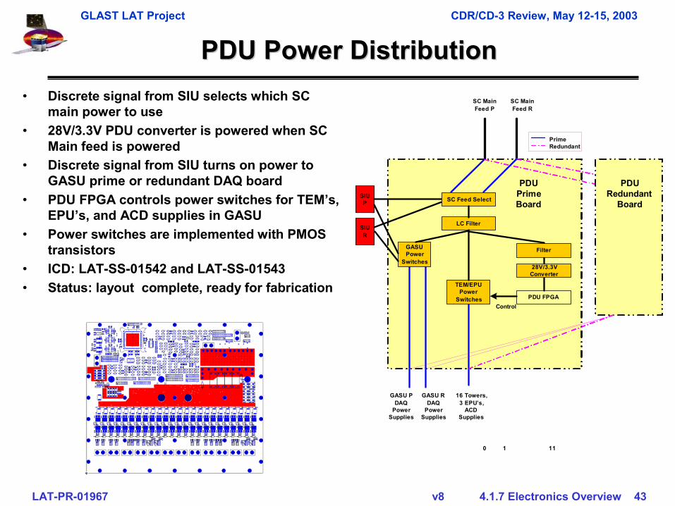
• Discrete signal from SIU selects which SC main power to use
• 28V/3.3V PDU converter is powered when SC Main feed is powered
• Discrete signal from SIU turns on power to GASU prime or redundant DAQ board
• PDU FPGA controls power switches for TEM’s, EPU’s, and ACD supplies in GASU
• Power switches are implemented with PMOS transistors
• ICD: LAT-SS-01542 and LAT-SS-01543• Status: layout complete, ready for fabrication
GLAST LAT Project CDR/CD-3 Review, May 12-15, 2003
LAT-PR-01967 v8 4.1.7 Electronics Overview 44
DAQ Thermal & MechanicalDAQ Thermal & Mechanical
• Thermal and Mechanical Analysis documented in LAT-TD-02138
GLAST LAT Project CDR/CD-3 Review, May 12-15, 2003
LAT-PR-01967 v8 4.1.7 Electronics Overview 45
ThermalThermal
• TEM 3.4 watts• TEM Power Supply (PS) 11.7 watts• GASU 24.9 watts• PDU 18.1 watts• EPU 24.3 watts• SIU 27.2 watts• Stackups
– TEM, TEM PS, EPU -> 39.4 watts– TEM, TEM PS, SIU -> 42.3 watts– TEM, TEM PS, PDU -> 33.2 watts– TEM, TEM PS, GASU ->27.5 watts
Assumptions• Thermal boundaries for DAQ
– -40C to +55C for Qualification– Uniform thermal connection to
X-LAT plates– Only thermal conduction
considered– No thermal conduction to
calorimeter base plates.– 100 OC maximum Si junction
temp• Thermal Resistances/Conductance's
– Al 6061 154 W/m-K– Polyimide 0.33 W/m-K– CV2943 adhesive 1.26*W/m-K– Wedge-Lok 0.14 OC/W, 2 each 6”– Actel FPGA 6.2 OC/W J-C– Thermal Via, 12 mil, 2*103 OC/W
each• 3.4 OC/W for an array of
64X8
GLAST LAT Project CDR/CD-3 Review, May 12-15, 2003
LAT-PR-01967 v8 4.1.7 Electronics Overview 46
SIU/EPU SIU/EPU StackupStackup
TEM, TEMTEM, TEM--PSU, and SIU/EPU/EMPTY StackPSU, and SIU/EPU/EMPTY Stack10x Typical10x Typical
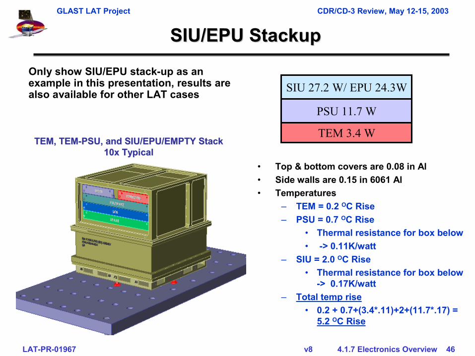
Only show SIU/EPU stack-up as an example in this presentation, results are also available for other LAT cases
• Top & bottom covers are 0.08 in Al• Side walls are 0.15 in 6061 Al• Temperatures
– TEM = 0.2 OC Rise – PSU = 0.7 OC Rise
• Thermal resistance for box below• -> 0.11K/watt
– SIU = 2.0 OC Rise• Thermal resistance for box below
-> 0.17K/watt– Total temp rise
• 0.2 + 0.7+(3.4*.11)+2+(11.7*.17) = 5.2 OC Rise
SIU 27.2 W/ EPU 24.3W
PSU 11.7 W
TEM 3.4 W
GLAST LAT Project CDR/CD-3 Review, May 12-15, 2003
LAT-PR-01967 v8 4.1.7 Electronics Overview 47
TEMTEM--PSUPSU--EPU/SIUEPU/SIU
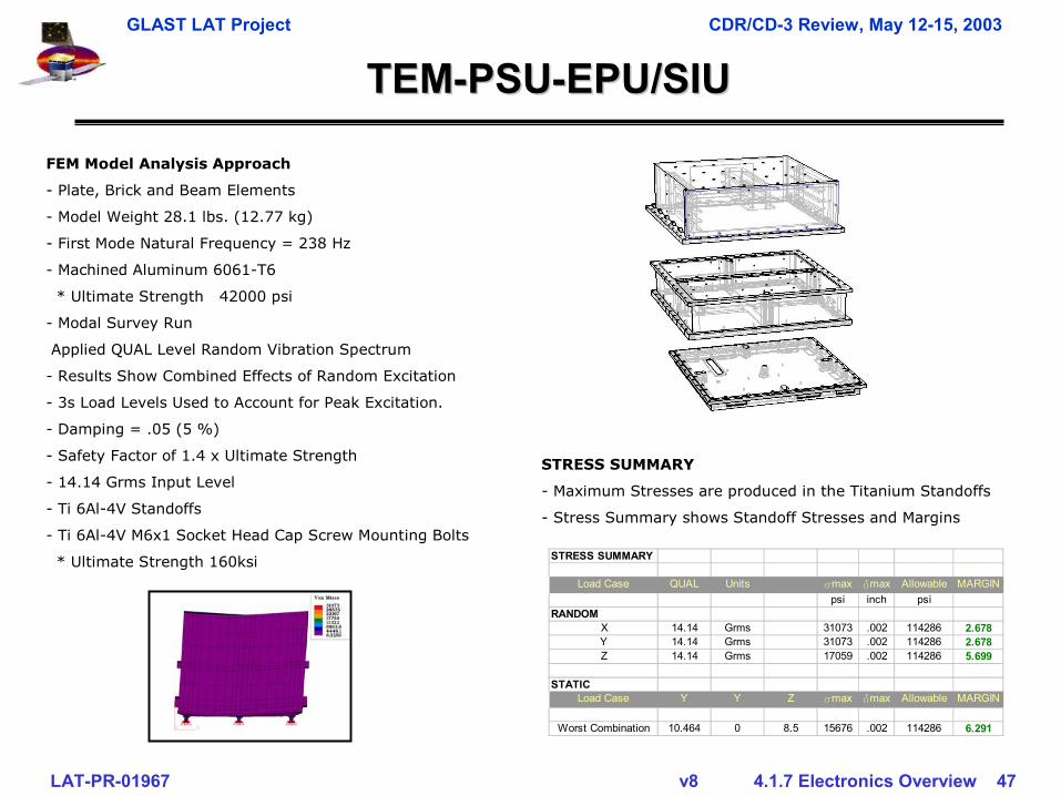
FEM Model Analysis Approach
- Plate, Brick and Beam Elements
- Model Weight 28.1 lbs. (12.77 kg)
- First Mode Natural Frequency = 238 Hz
- Machined Aluminum 6061-T6
* Ultimate Strength 42000 psi
- Modal Survey Run
Applied QUAL Level Random Vibration Spectrum
- Results Show Combined Effects of Random Excitation
- 3s Load Levels Used to Account for Peak Excitation.
- Damping = .05 (5 %)
- Safety Factor of 1.4 x Ultimate Strength
- 14.14 Grms Input Level
- Ti 6Al-4V Standoffs
- Ti 6Al-4V M6x1 Socket Head Cap Screw Mounting Bolts
* Ultimate Strength 160ksi
STRESS SUMMARY
- Maximum Stresses are produced in the Titanium Standoffs
- Stress Summary shows Standoff Stresses and Margins
STRESS SUMMARY
Load Case QUAL Units smax dmax Allowable MARGINpsi inch psi
RANDOMX 14.14 Grms 31073 .002 114286 2.678Y 14.14 Grms 31073 .002 114286 2.678Z 14.14 Grms 17059 .002 114286 5.699
STATICLoad Case Y Y Z smax dmax Allowable MARGIN
Worst Combination 10.464 0 8.5 15676 .002 114286 6.291
GLAST LAT Project CDR/CD-3 Review, May 12-15, 2003
LAT-PR-01967 v8 4.1.7 Electronics Overview 48
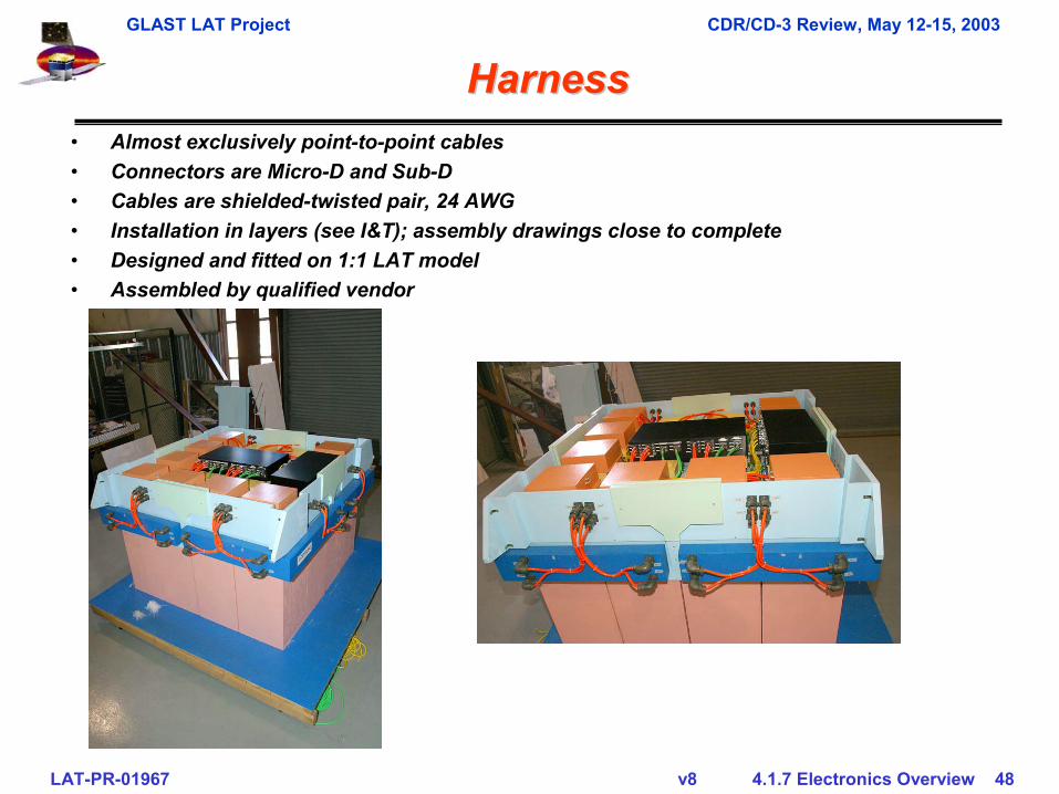
HarnessHarness• Almost exclusively point-to-point cables• Connectors are Micro-D and Sub-D• Cables are shielded-twisted pair, 24 AWG• Installation in layers (see I&T); assembly drawings close to complete• Designed and fitted on 1:1 LAT model• Assembled by qualified vendor
GLAST LAT Project CDR/CD-3 Review, May 12-15, 2003
LAT-PR-01967 v8 4.1.7 Electronics Overview 49
Verification & TestVerification & Test
GLAST LAT Project CDR/CD-3 Review, May 12-15, 2003
LAT-PR-01967 v8 4.1.7 Electronics Overview 50
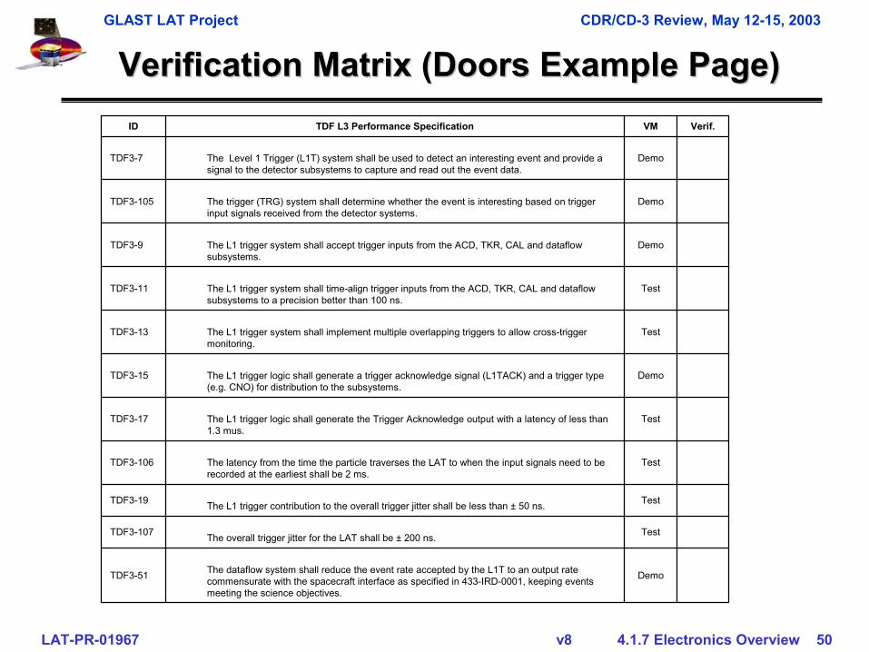
Verification Matrix (Doors Example Page)Verification Matrix (Doors Example Page)
DemoThe dataflow system shall reduce the event rate accepted by the L1T to an output rate commensurate with the spacecraft interface as specified in 433-IRD-0001, keeping events meeting the science objectives.
TDF3-51
TestThe overall trigger jitter for the LAT shall be ± 200 ns. TDF3-107
TestThe L1 trigger contribution to the overall trigger jitter shall be less than ± 50 ns.TDF3-19
TestThe latency from the time the particle traverses the LAT to when the input signals need to be recorded at the earliest shall be 2 ms.
TDF3-106
TestThe L1 trigger logic shall generate the Trigger Acknowledge output with a latency of less than 1.3 mus.
TDF3-17
DemoThe L1 trigger logic shall generate a trigger acknowledge signal (L1TACK) and a trigger type (e.g. CNO) for distribution to the subsystems.
TDF3-15
TestThe L1 trigger system shall implement multiple overlapping triggers to allow cross-trigger monitoring.
TDF3-13
TestThe L1 trigger system shall time-align trigger inputs from the ACD, TKR, CAL and dataflow subsystems to a precision better than 100 ns.
TDF3-11
DemoThe L1 trigger system shall accept trigger inputs from the ACD, TKR, CAL and dataflow subsystems.
TDF3-9
DemoThe trigger (TRG) system shall determine whether the event is interesting based on trigger input signals received from the detector systems.
TDF3-105
DemoThe Level 1 Trigger (L1T) system shall be used to detect an interesting event and provide a signal to the detector subsystems to capture and read out the event data.
TDF3-7
Verif.VMTDF L3 Performance SpecificationID
GLAST LAT Project CDR/CD-3 Review, May 12-15, 2003
LAT-PR-01967 v8 4.1.7 Electronics Overview 51
Hardware Mechanical Electrical Environmental/Other Comments
Ass
embl
y Le
vel
Component (ITEM) Qua
ntity
Uni
t Typ
e
Sta
tic L
oad
Sin
e B
urst
Sin
e S
wee
p
Ran
dom
Vib
Aco
ustic
Pre
ssur
e P
rofil
e
Mas
s P
rope
rty
Inte
rface
Ver
ifica
tion
EM
I/EM
C
ES
D C
ompa
tibili
ty (G
rndi
ng)
Func
tiona
l/Per
form
ance
Ther
mal
Vac
uum
Ther
mal
Bal
ance
Ther
mal
Cyc
le
Hum
idity
Bac
kout
Rad
iatio
n
Insp
ectio
n
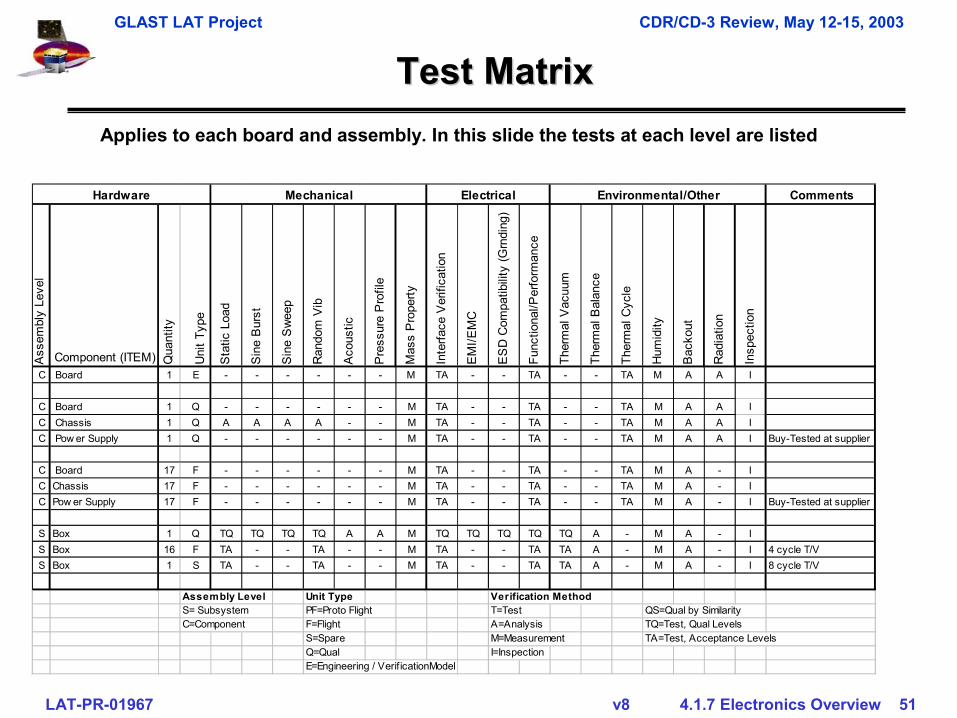
C Board 1 E - - - - - - M TA - - TA - - TA M A A I
C Board 1 Q - - - - - - M TA - - TA - - TA M A A I C Chassis 1 Q A A A A - - M TA - - TA - - TA M A A I C Pow er Supply 1 Q - - - - - - M TA - - TA - - TA M A A I Buy-Tested at supplier
C Board 17 F - - - - - - M TA - - TA - - TA M A - I C Chassis 17 F - - - - - - M TA - - TA - - TA M A - I C Pow er Supply 17 F - - - - - - M TA - - TA - - TA M A - I Buy-Tested at supplier
S Box 1 Q TQ TQ TQ TQ A A M TQ TQ TQ TQ TQ A - M A - I S Box 16 F TA - - TA - - M TA - - TA TA A - M A - I 4 cycle T/VS Box 1 S TA - - TA - - M TA - - TA TA A - M A - I 8 cycle T/V
Assembly Level Unit Type Verification MethodS= Subsystem PF=Proto Flight T=Test QS=Qual by SimilarityC=Component F=Flight A=Analysis TQ=Test, Qual Levels
S=Spare M=Measurement TA=Test, Acceptance LevelsQ=Qual I=InspectionE=Engineering / Verif icationModel
Test MatrixTest MatrixApplies to each board and assembly. In this slide the tests at each level are listed
GLAST LAT Project CDR/CD-3 Review, May 12-15, 2003
LAT-PR-01967 v8 4.1.7 Electronics Overview 52
Testing PlanTesting Plan
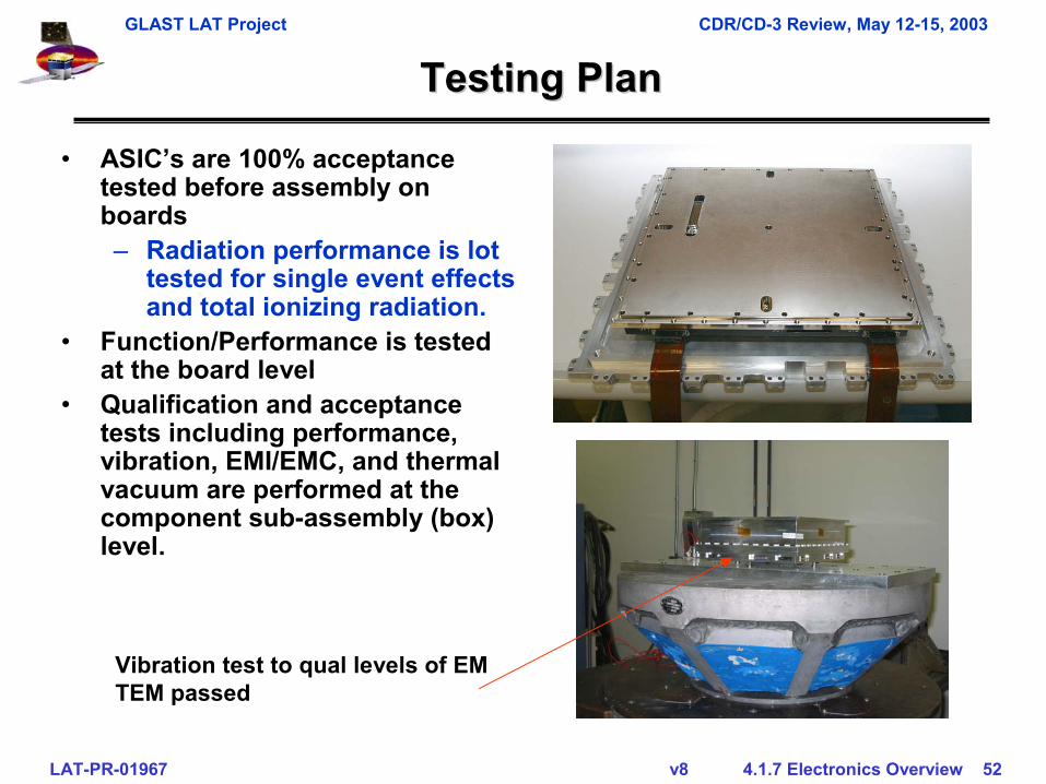
• ASIC’s are 100% acceptance tested before assembly on boards– Radiation performance is lot
tested for single event effects and total ionizing radiation.
• Function/Performance is tested at the board level
• Qualification and acceptance tests including performance, vibration, EMI/EMC, and thermal vacuum are performed at the component sub-assembly (box) level.
Vibration test to qual levels of EM TEM passed
GLAST LAT Project CDR/CD-3 Review, May 12-15, 2003
LAT-PR-01967 v8 4.1.7 Electronics Overview 53
Verification & TestVerification & Test
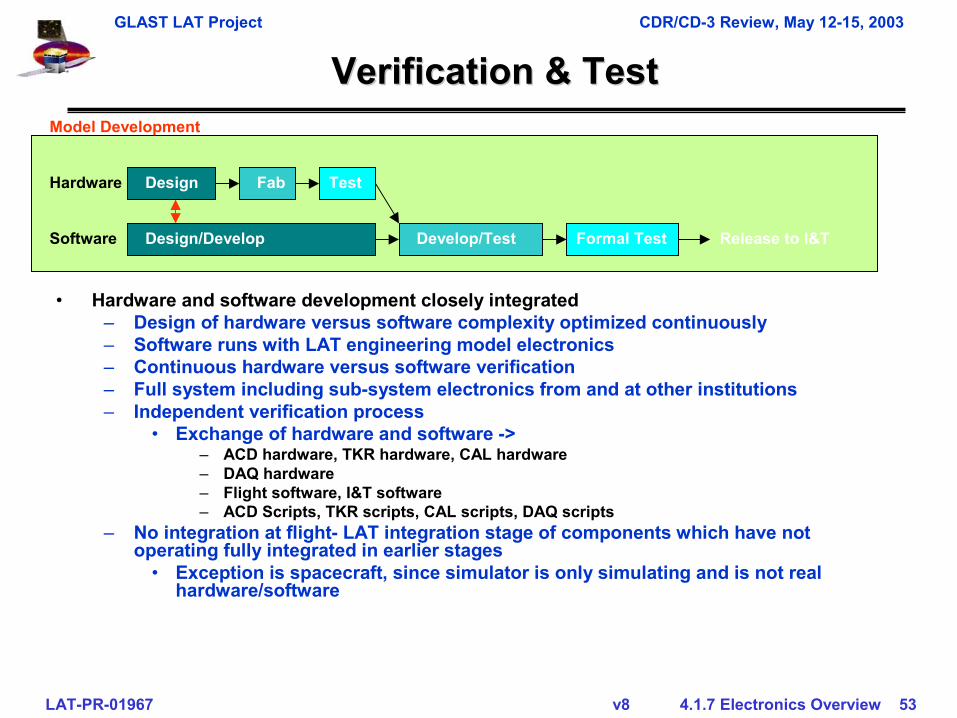
• Hardware and software development closely integrated– Design of hardware versus software complexity optimized continuously– Software runs with LAT engineering model electronics– Continuous hardware versus software verification– Full system including sub-system electronics from and at other institutions– Independent verification process
• Exchange of hardware and software ->– ACD hardware, TKR hardware, CAL hardware– DAQ hardware– Flight software, I&T software– ACD Scripts, TKR scripts, CAL scripts, DAQ scripts
– No integration at flight- LAT integration stage of components which have not operating fully integrated in earlier stages
• Exception is spacecraft, since simulator is only simulating and is not real hardware/software
Model Development
DesignHardware Fab Test
Design/Develop Develop/Test Formal TestSoftware Release to I&T
GLAST LAT Project CDR/CD-3 Review, May 12-15, 2003
LAT-PR-01967 v8 4.1.7 Electronics Overview 54
Verification & Test (Verification & Test (Con’tCon’t))
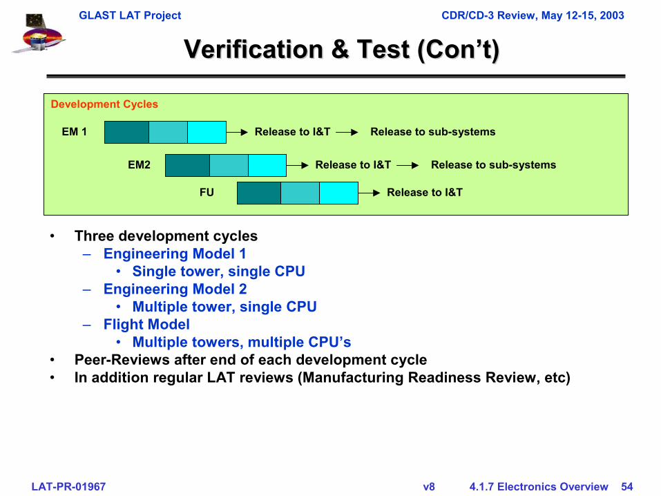
• Three development cycles– Engineering Model 1
• Single tower, single CPU– Engineering Model 2
• Multiple tower, single CPU– Flight Model
• Multiple towers, multiple CPU’s• Peer-Reviews after end of each development cycle• In addition regular LAT reviews (Manufacturing Readiness Review, etc)
Development Cycles
EM 1
EM2
Release to I&T
Release to I&T
Release to I&TFU
Release to sub-systems
Release to sub-systems
GLAST LAT Project CDR/CD-3 Review, May 12-15, 2003
LAT-PR-01967 v8 4.1.7 Electronics Overview 55
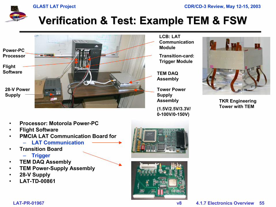
Verification & Test: Example TEM & FSWVerification & Test: Example TEM & FSW
• Processor: Motorola Power-PC• Flight Software• PMCIA LAT Communication Board for
– LAT Communication• Transition Board
– Trigger• TEM DAQ Assembly• TEM Power-Supply Assembly• 28-V Supply• LAT-TD-00861
Tower Power Supply Assembly
(1.5V/2.5V/3.3V/ 0-100V/0-150V)
TEM DAQ Assembly
LCB: LAT Communication Module
Transition-card: Trigger Module
28-V Power Supply
Power-PC Processor
Flight Software
TKR Engineering Tower with TEM
GLAST LAT Project CDR/CD-3 Review, May 12-15, 2003
LAT-PR-01967 v8 4.1.7 Electronics Overview 56
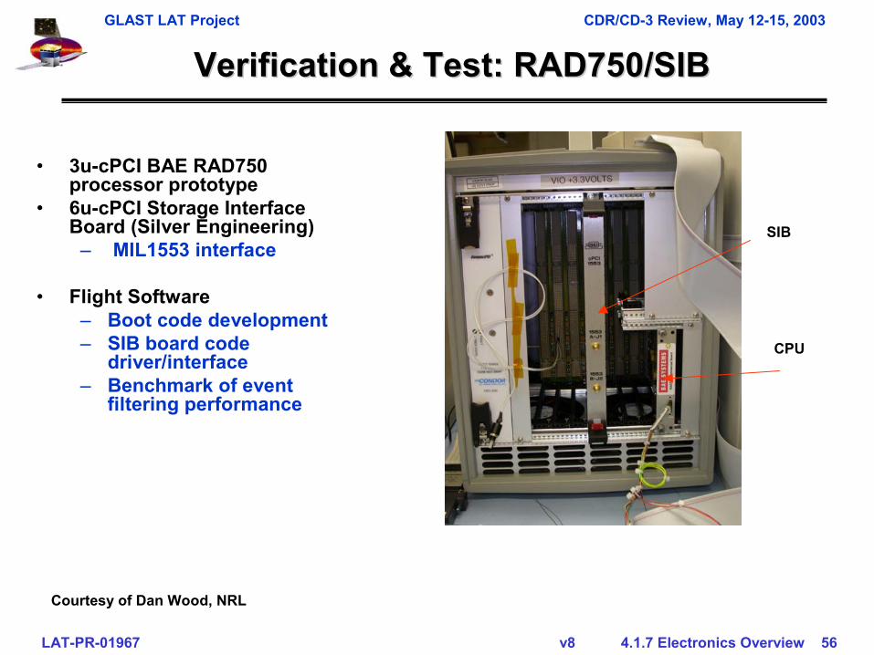
Verification & Test: RAD750/SIBVerification & Test: RAD750/SIB
• 3u-cPCI BAE RAD750 processor prototype
• 6u-cPCI Storage Interface Board (Silver Engineering)
– MIL1553 interface
• Flight Software– Boot code development– SIB board code
driver/interface– Benchmark of event
filtering performance
Courtesy of Dan Wood, NRL
SIB
CPU
GLAST LAT Project CDR/CD-3 Review, May 12-15, 2003
LAT-PR-01967 v8 4.1.7 Electronics Overview 57
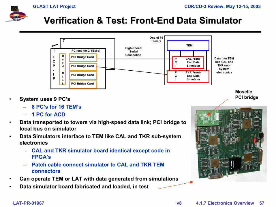
Verification & Test: FrontVerification & Test: Front--End Data SimulatorEnd Data Simulator
PC (one for 2 TEM’s)
CAL Front-End DataSimulator
PCI Bridge Card
High-SpeedSerial
Connection
PCI Bridge Card
0
7
PCI Bridge Card
PCI Bridge Card
TKR Front-End DataSimulator
PCI
PCI
TEM
Data into TEMlike CAL and
TKR sub-system
electronics
TCP-IP
Hard-Disk
One of 16Towers
• System uses 9 PC’s– 8 PC’s for 16 TEM’s– 1 PC for ACD
• Data transported to towers via high-speed data link; PCI bridge to local bus on simulator
• Data Simulators interface to TEM like CAL and TKR sub-system electronics
– CAL and TKR simulator board identical except code in FPGA’s
– Patch cable connect simulator to CAL and TKR TEM connectors
• Can operate TEM or LAT with data generated from simulations• Data simulator board fabricated and loaded, in test
MosellePCI bridge
GLAST LAT Project CDR/CD-3 Review, May 12-15, 2003
LAT-PR-01967 v8 4.1.7 Electronics Overview 58
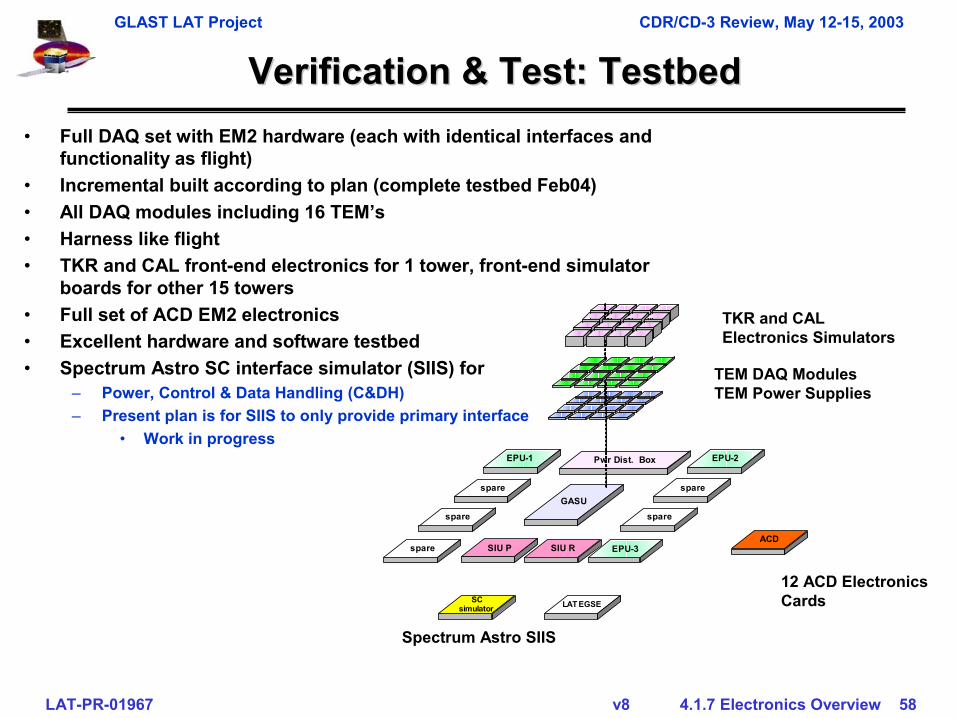
Verification & Test: Verification & Test: TestbedTestbed
spare
EPU-3
EPU-2EPU-1
spare spare
Pwr Dist. Box
GASU
spare
spare
ACD
SCsimulator LAT EGSE
SIU P SIU R
TEM DAQ Modules TEM Power Supplies
TKR and CAL Electronics Simulators
12 ACD Electronics Cards
• Full DAQ set with EM2 hardware (each with identical interfaces and functionality as flight)
• Incremental built according to plan (complete testbed Feb04)• All DAQ modules including 16 TEM’s• Harness like flight• TKR and CAL front-end electronics for 1 tower, front-end simulator
boards for other 15 towers• Full set of ACD EM2 electronics• Excellent hardware and software testbed• Spectrum Astro SC interface simulator (SIIS) for
– Power, Control & Data Handling (C&DH)– Present plan is for SIIS to only provide primary interface
• Work in progress
Spectrum Astro SIIS
GLAST LAT Project CDR/CD-3 Review, May 12-15, 2003
LAT-PR-01967 v8 4.1.7 Electronics Overview 59
FabricationFabrication
GLAST LAT Project CDR/CD-3 Review, May 12-15, 2003
LAT-PR-01967 v8 4.1.7 Electronics Overview 60
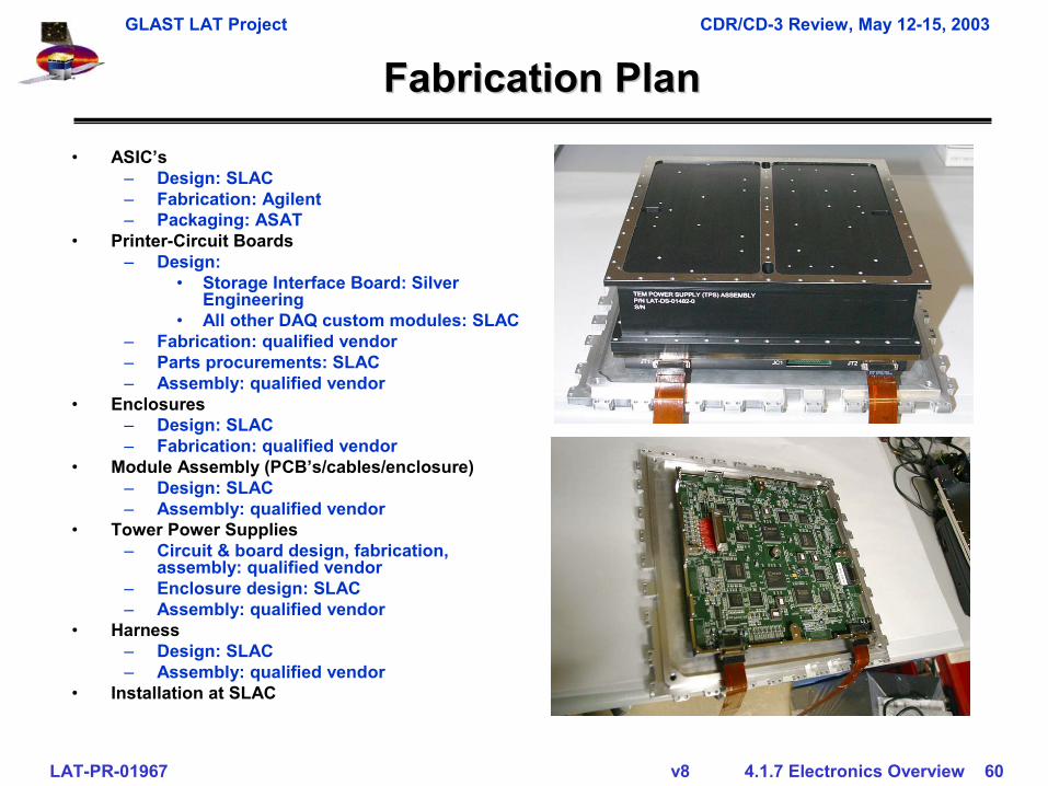
Fabrication PlanFabrication Plan• ASIC’s
– Design: SLAC– Fabrication: Agilent– Packaging: ASAT
• Printer-Circuit Boards– Design:
• Storage Interface Board: Silver Engineering
• All other DAQ custom modules: SLAC– Fabrication: qualified vendor– Parts procurements: SLAC– Assembly: qualified vendor
• Enclosures– Design: SLAC– Fabrication: qualified vendor
• Module Assembly (PCB’s/cables/enclosure)– Design: SLAC– Assembly: qualified vendor
• Tower Power Supplies– Circuit & board design, fabrication,
assembly: qualified vendor– Enclosure design: SLAC– Assembly: qualified vendor
• Harness– Design: SLAC– Assembly: qualified vendor
• Installation at SLAC
GLAST LAT Project CDR/CD-3 Review, May 12-15, 2003
LAT-PR-01967 v8 4.1.7 Electronics Overview 61
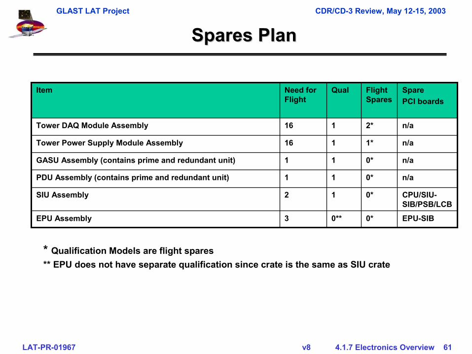
Spares PlanSpares Plan
0*
0*
0*
0*
1*
2*
Flight Spares
0**
1
1
1
1
1
Qual
EPU-SIB3EPU Assembly
n/a1GASU Assembly (contains prime and redundant unit)
n/a1PDU Assembly (contains prime and redundant unit)
CPU/SIU-SIB/PSB/LCB
2SIU Assembly
n/a16Tower Power Supply Module Assembly
n/a16Tower DAQ Module Assembly
SparePCI boards
Need for Flight
Item
* Qualification Models are flight spares** EPU does not have separate qualification since crate is the same as SIU crate
GLAST LAT Project CDR/CD-3 Review, May 12-15, 2003
LAT-PR-01967 v8 4.1.7 Electronics Overview 62
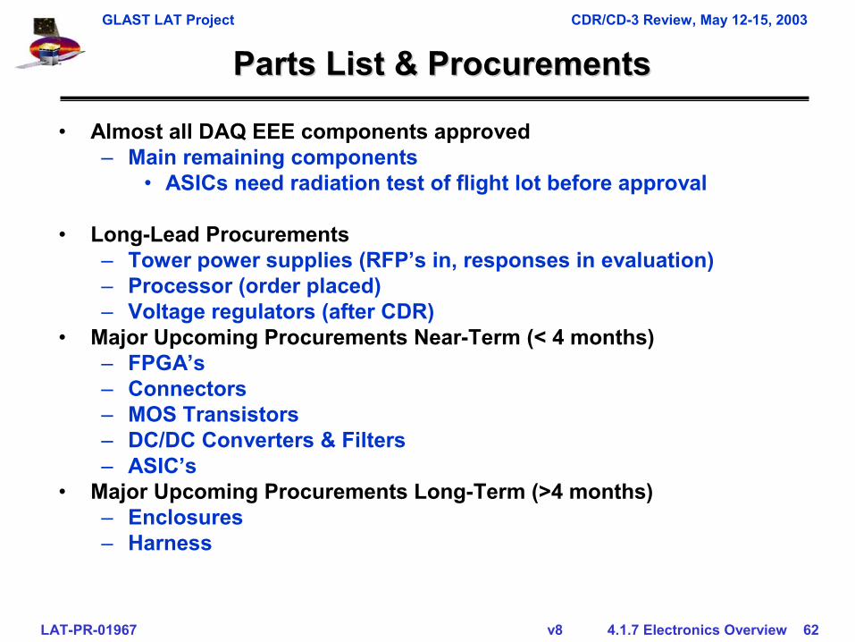
Parts List & ProcurementsParts List & Procurements
• Almost all DAQ EEE components approved– Main remaining components
• ASICs need radiation test of flight lot before approval
• Long-Lead Procurements– Tower power supplies (RFP’s in, responses in evaluation)– Processor (order placed)– Voltage regulators (after CDR)
• Major Upcoming Procurements Near-Term (< 4 months)– FPGA’s– Connectors– MOS Transistors– DC/DC Converters & Filters – ASIC’s
• Major Upcoming Procurements Long-Term (>4 months)– Enclosures– Harness
GLAST LAT Project CDR/CD-3 Review, May 12-15, 2003
LAT-PR-01967 v8 4.1.7 Electronics Overview 63
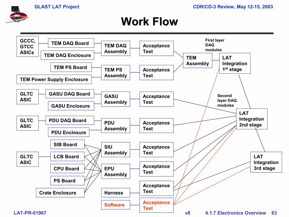
Work FlowWork Flow
TEM DAQ Assembly
TEM DAQ BoardGCCC, GTCC ASICs TEM DAQ Enclosure
TEM PS Assembly
TEM PS Board
TEM Power Supply Enclosure
GASU Assembly
GASU DAQ BoardGLTC ASIC
GASU Enclosure
PDU Assembly
PDU DAQ BoardGLTC ASIC
PDU Enclosure
SIU Assembly
SIB Board
Crate Enclosure
LCB Board
CPU Board
PS Board
EPU Assembly
Harness
TEM Assembly
LAT Integration 1st stage
Acceptance Test
Acceptance Test
Acceptance Test
Acceptance Test
Acceptance Test
Acceptance Test
GLTC ASIC
Acceptance Test
LAT Integration 2nd stage
LAT Integration 3rd stage
First layer DAQ modules
Second layer DAQ modules
Software Acceptance Test
GLAST LAT Project CDR/CD-3 Review, May 12-15, 2003
LAT-PR-01967 v8 4.1.7 Electronics Overview 64
Work Authorization and Manufacturing Work Authorization and Manufacturing FlowFlow
• All manufacturing tasks will be performed on approved Assembly and Inspection Data Sheets (work orders)
• Order parts per LAT procedures• Kitting per LAT procedures• End-item assembly parts are issued to assembly work orders
and sent to assembly supplier(s)• Assembly and test instructions• End items are received into project stores as they are received
from the assembly supplier• End items are issued to test work order for acceptance testing• Upon completion of acceptance testing, end items are returned
to project stores where are ready for issue to I&T• More detail, see appendix
GLAST LAT Project CDR/CD-3 Review, May 12-15, 2003
LAT-PR-01967 v8 4.1.7 Electronics Overview 65
Issues, Risk & Mitigation PlansIssues, Risk & Mitigation Plans
GLAST LAT Project CDR/CD-3 Review, May 12-15, 2003
LAT-PR-01967 v8 4.1.7 Electronics Overview 66
Technical Issues and StatusTechnical Issues and Status
• No known technical issues in respect to functionality and performance except potentially– TEM GTCC and GCCC ASICs
• Need radiation testing
GLAST LAT Project CDR/CD-3 Review, May 12-15, 2003
LAT-PR-01967 v8 4.1.7 Electronics Overview 67
RiskRisk
• No single DAQ system failure can degrade LAT Electronics capabilities below minimum science requirements
• Failure in SIU, PDU, or GASU can require use of the respective redundant unit
• Failure in one of the two EPU’s can require use of the redundant EPU unit. A second failure will reduce the available EPU CPU power by a factor of 2
• Failure in TEM power-supply or TEM DAQ module can lead to– Loss of a full tower (most of the assembly is single string)– Loss of the calorimeter or parts of it– Loss of the tracker or parts of it
GLAST LAT Project CDR/CD-3 Review, May 12-15, 2003
LAT-PR-01967 v8 4.1.7 Electronics Overview 68
Electronics Risk SummaryElectronics Risk Summary
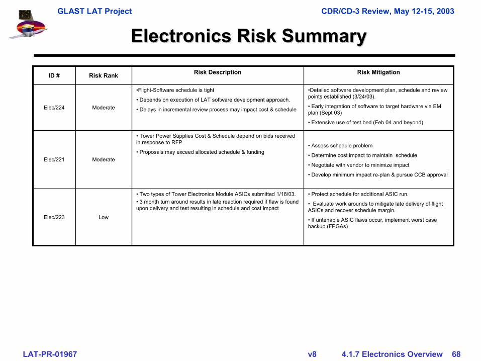
• Assess schedule problem
• Determine cost impact to maintain schedule
• Negotiate with vendor to minimize impact
• Develop minimum impact re-plan & pursue CCB approval
• Tower Power Supplies Cost & Schedule depend on bids received in response to RFP
• Proposals may exceed allocated schedule & fundingModerateElec/221
• Protect schedule for additional ASIC run.
• Evaluate work arounds to mitigate late delivery of flight ASICs and recover schedule margin.
• If untenable ASIC flaws occur, implement worst case backup (FPGAs)
• Two types of Tower Electronics Module ASICs submitted 1/18/03. • 3 month turn around results in late reaction required if flaw is found upon delivery and test resulting in schedule and cost impact
LowElec/223
•Detailed software development plan, schedule and review points established (3/24/03).
• Early integration of software to target hardware via EM plan (Sept 03)
• Extensive use of test bed (Feb 04 and beyond)
•Flight-Software schedule is tight
• Depends on execution of LAT software development approach.
• Delays in incremental review process may impact cost & scheduleModerateElec/224
Risk MitigationRisk DescriptionRisk RankID #
GLAST LAT Project CDR/CD-3 Review, May 12-15, 2003
LAT-PR-01967 v8 4.1.7 Electronics Overview 69
Cost & ScheduleCost & Schedule
GLAST LAT Project CDR/CD-3 Review, May 12-15, 2003
LAT-PR-01967 v8 4.1.7 Electronics Overview 70
CCB Actions Affecting 4.1.7CCB Actions Affecting 4.1.7
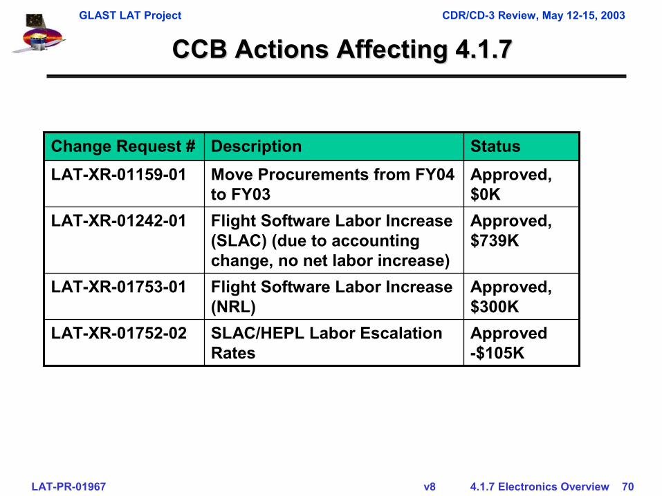
Approved -$105K
SLAC/HEPL Labor Escalation Rates
LAT-XR-01752-02
Approved, $300K
Flight Software Labor Increase (NRL)
LAT-XR-01753-01
Approved, $0K
Move Procurements from FY04 to FY03
LAT-XR-01159-01
Approved, $739K
Flight Software Labor Increase (SLAC) (due to accounting change, no net labor increase)
LAT-XR-01242-01
StatusDescription Change Request #
GLAST LAT Project CDR/CD-3 Review, May 12-15, 2003
LAT-PR-01967 v8 4.1.7 Electronics Overview 71
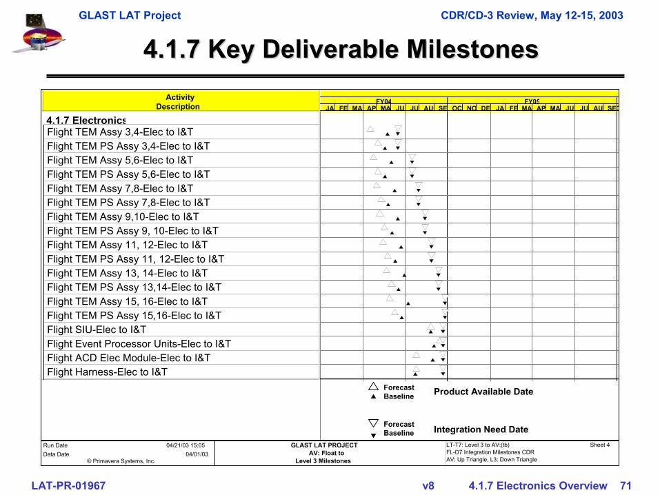
4.1.7 Key Deliverable Milestones4.1.7 Key Deliverable Milestones
Product Available Date
Integration Need Date
ForecastBaseline
ForecastBaseline
ActivityDescription
4.1.7 ElectronicsFlight TEM Assy 3,4-Elec to I&TFlight TEM PS Assy 3,4-Elec to I&TFlight TEM Assy 5,6-Elec to I&TFlight TEM PS Assy 5,6-Elec to I&TFlight TEM Assy 7,8-Elec to I&TFlight TEM PS Assy 7,8-Elec to I&TFlight TEM Assy 9,10-Elec to I&TFlight TEM PS Assy 9, 10-Elec to I&TFlight TEM Assy 11, 12-Elec to I&TFlight TEM PS Assy 11, 12-Elec to I&TFlight TEM Assy 13, 14-Elec to I&TFlight TEM PS Assy 13,14-Elec to I&TFlight TEM Assy 15, 16-Elec to I&TFlight TEM PS Assy 15,16-Elec to I&TFlight SIU-Elec to I&TFlight Event Processor Units-Elec to I&TFlight ACD Elec Module-Elec to I&TFlight Harness-Elec to I&T
FY04 FY05JANFEBMARAPRMAY JUN JUL AUGSE OCT NO DEC JANFE MA APRMAY JUN JUL AU SEPC
© Primavera Systems, Inc.
Run Date 04/21/03 15:05Data Date 04/01/03
GLAST LAT PROJECTAV: Float to
Level 3 Milestones
LT-T7: Level 3 to AV:(tb)FL-D7 Integration Milestones CDRAV: Up Triangle, L3: Down Triangle
Sheet 4
GLAST LAT Project CDR/CD-3 Review, May 12-15, 2003
LAT-PR-01967 v8 4.1.7 Electronics Overview 72
Critical PathCritical Path
• TEM DAQ Assembly– Flight TEM DAQ PC Board fab and loading Feb 04
• Requires flight TEM ASICs• Tower Power Supplies
– Flight assemblies by March 04• RFP came back, being evaluated
– Needs negotiations with supplier
GLAST LAT Project CDR/CD-3 Review, May 12-15, 2003
LAT-PR-01967 v8 4.1.7 Electronics Overview 73
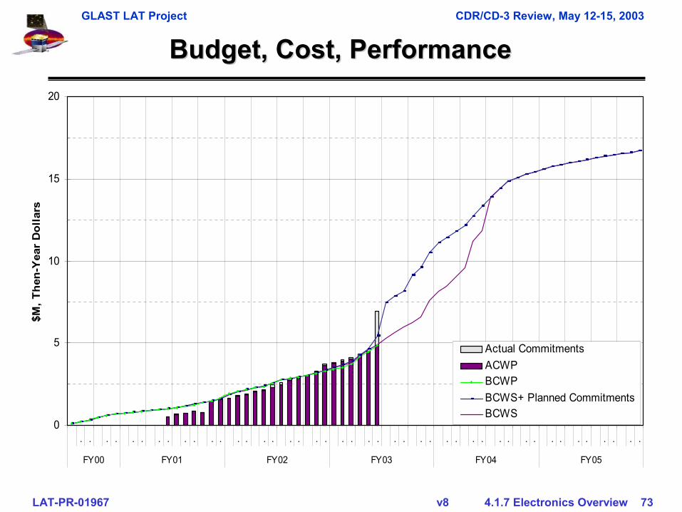
Budget, Cost, PerformanceBudget, Cost, Performance
0
5
10
15
20
. . . . . . . . . . . . . . . . . . . . . . . . . . . . . . . . . . . . . . . . . . . .
FY00 FY01 FY02 FY03 FY04 FY05
$M, T
hen-
Yea
r D
olla
rs
Actual CommitmentsACWPBCWPBCWS+ Planned CommitmentsBCWS
GLAST LAT Project CDR/CD-3 Review, May 12-15, 2003
LAT-PR-01967 v8 4.1.7 Electronics Overview 74
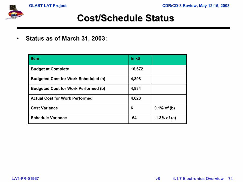
Cost/Schedule StatusCost/Schedule Status
0.1% of (b)6Cost Variance
4,898Budgeted Cost for Work Scheduled (a)
4,834Budgeted Cost for Work Performed (b)
4,828Actual Cost for Work Performed
-1.3% of (a)-64Schedule Variance
16,672Budget at Complete
In k$Item
• Status as of March 31, 2003:
GLAST LAT Project CDR/CD-3 Review, May 12-15, 2003
LAT-PR-01967 v8 4.1.7 Electronics Overview 75
SummarySummary
• Most documentation in release cycle– Have completed parts list for each module, submitted to Parts
Control Board. Most of those parts (90%) were already approved by PCB on DAQ parts list.
– Need to complete Parts Stress Analysis for each module, close tocomplete, to be submitted to PCB one week after CDR
• No major technical issues• Design mature• Technical, cost & schedule status consistent with baseline objectives• Management structure in place to guide the project to completion
• Manufacturing process defined
• Ready to buy flight components
GLAST LAT Project CDR/CD-3 Review, May 12-15, 2003
LAT-PR-01967 v8 4.1.7 Electronics Overview 76
GLAST LAT Project CDR/CD-3 Review, May 12-15, 2003
LAT-PR-01967 v8 4.1.7 Electronics Overview 77
BackupBackup
GLAST LAT Project CDR/CD-3 Review, May 12-15, 2003
LAT-PR-01967 v8 4.1.7 Electronics Overview 78
Work AuthorizationWork Authorization
• All manufacturing tasks will be performed on approved Assembly and Inspection Data Sheets (work orders)– Responsible Engineer– Manufacturing Engineer– Quality Engineer
• Assembly or test instructions– Step-by-step procedures– Provisions for operator and inspector sign off– May reference other documents, such as test procedures
• Work order remains with item until item has passed final inspection
• Work order completion results in the delivery of an item to project stores
• Completed work orders are archived by LAT Quality Assurance Manager
GLAST LAT Project CDR/CD-3 Review, May 12-15, 2003
LAT-PR-01967 v8 4.1.7 Electronics Overview 79
Manufacturing Flow Manufacturing Flow -- ContinuedContinued
• Order Parts– All parts approved and on the program PIL– PWBs to be ordered from qualified suppliers– Mechanical parts manufactured at SLAC and qualified
machine shops– All parts received into LAT project stores
• Kitting– Triggered by Assembly and Inspection Data Sheet (work
order)– Parts issued from inventory to kit
GLAST LAT Project CDR/CD-3 Review, May 12-15, 2003
LAT-PR-01967 v8 4.1.7 Electronics Overview 80
Manufacturing Flow Manufacturing Flow –– ContinuedContinued
• Assembly– Performed by approved suppliers– Completed assembly entered into inventory to close work
order Circuit cards tested at SLAC– CCAs issued to test work order– CCAs are tested and returned to stores to close out the test
work order• End-item assembly parts are issued to assembly work orders
and sent to assembly supplier(s)• End items are received into project stores as they are received
from the assembly supplier• End items are issued to test work order for acceptance testing• Upon completion of acceptance testing, end items are returned
to project stores where are ready for issue to I&T
GLAST LAT Project CDR/CD-3 Review, May 12-15, 2003
LAT-PR-01967 v8 4.1.7 Electronics Overview 81
Manpower PlanManpower Plan
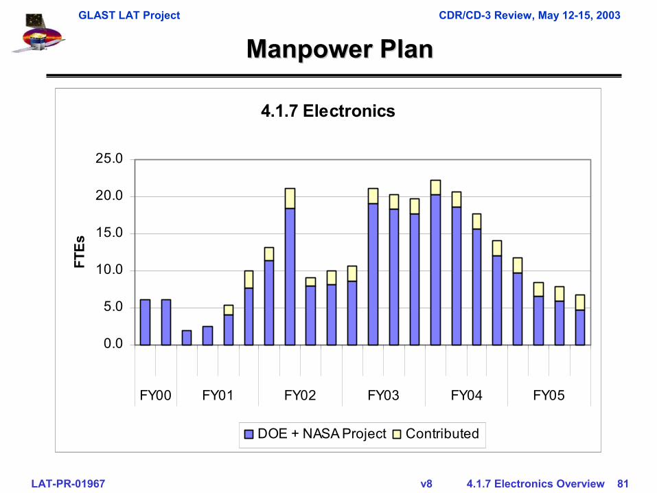
4.1.7 Electronics
0.0
5.0
10.0
15.0
20.0
25.0
FY00 FY01 FY02 FY03 FY04 FY05
FTEs
DOE + NASA Project Contributed
GLAST LAT Project CDR/CD-3 Review, May 12-15, 2003
LAT-PR-01967 v8 4.1.7 Electronics Overview 82
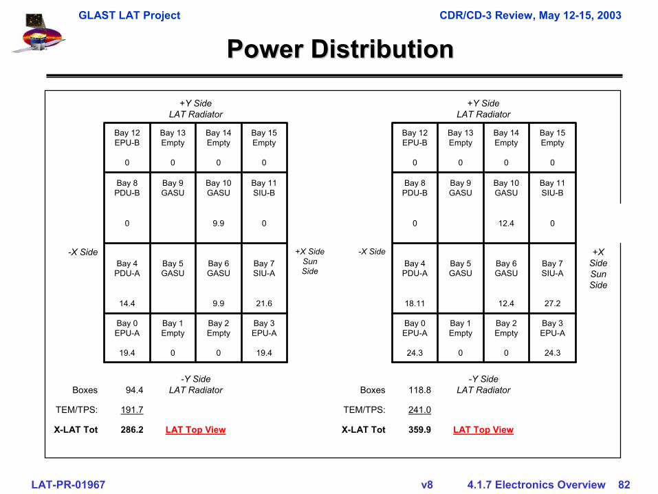
Power DistributionPower Distribution
LAT Top View359.9X-LAT TotLAT Top View286.2X-LAT Tot
241.0TEM/TPS:191.7TEM/TPS:
-Y SideLAT Radiator118.8Boxes
-Y SideLAT Radiator94.4Boxes
24.30024.319.40019.4
Bay 3EPU-A
Bay 2Empty
Bay 1Empty
Bay 0EPU-A
Bay 3EPU-A
Bay 2Empty
Bay 1Empty
Bay 0EPU-A
27.212.418.1121.69.914.4
+X SideSun Side
Bay 7SIU-A
Bay 6GASU
Bay 5GASU
Bay 4PDU-A
-X Side+X SideSun Side
Bay 7SIU-A
Bay 6GASU
Bay 5GASU
Bay 4PDU-A
-X Side
012.4009.90
Bay 11SIU-B
Bay 10GASU
Bay 9GASU
Bay 8PDU-B
Bay 11SIU-B
Bay 10GASU
Bay 9GASU
Bay 8PDU-B
00000000
Bay 15Empty
Bay 14Empty
Bay 13Empty
Bay 12EPU-B
Bay 15Empty
Bay 14Empty
Bay 13Empty
Bay 12EPU-B
+Y SideLAT Radiator
+Y SideLAT Radiator
GLAST LAT Project CDR/CD-3 Review, May 12-15, 2003
LAT-PR-01967 v8 4.1.7 Electronics Overview 83
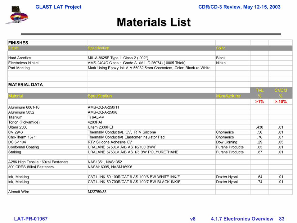
Materials ListMaterials ListFINISHESFinish Specification Color
Hard Anodize MIL-A-8625F Type III Class 2 (.002") BlackElectroless Nickel AMS-2404C Class 1 Grade A (MIL-C-26074) (.0005 Thick) NickelPart Marking Mark Using Epoxy Ink A-A-56032 5mm Characters, Color: Black ro White
MATERIAL DATATML CVCM
Material Specification Manufacturer % %>1% >.10%
Aluminum 6061-T6 AMS-QQ-A-250/11Aluminum 5052 AMS-QQ-A-250/8Titanium Ti 6AL-4VTorlon (Polyamide) 4203PAIUltem 2300 Ultem 2300PEI .430 .01CV 2943 Thermally Conductive, CV, RTV Silicone Chomerics .50 .01Cho-Therm 1671 Thermally Conductive Elastomer Insulator Pad Chomerics .76 .07DC 6-1104 RTV Silicone Adhesive CV Dow Corning .29 .05Conformal Coating URALANE 5750LV A/B AS 18/100 BW/F Furane Products .65 .01Staking URALANE 5753LV A/B AS 1/5 BW POLYURETHANE Furane Products .87 .01
A286 High Tensile 160ksi Fasteners NAS1351, NAS1352300 CRES 80ksi Fasteners NASM16995, NASM16996
Ink, Marking CAT-L-INK 50-100R/CAT 9 AS 100/6 BW WHITE INK/F Dexter Hysol .64 .01Ink, Marking CAT-L-INK 50-700R/CAT 9 AS 100/7 BW BLACK INK/F Dexter Hysol .74 .01
Aircraft Wire M22759/33
GLAST LAT Project CDR/CD-3 Review, May 12-15, 2003
LAT-PR-01967 v8 4.1.7 Electronics Overview 84
EEE Parts ListEEE Parts List
• Parts list submitted to Parts Control Board– Resistors– Capacitors– Connectors/wire– Integrated Circuits
• ACTEL 54SX32/72 FPGA• BAE FIFO• INTERSIL POR• HONEYWELL RAM• Summit MIL1553 IC
• Almost all parts are approved• Main parts remaining are
– ASIC’s• Requires radiation testing on flight production, can only
be implemented when flight-production is in hand