Embed Size (px)
Citation preview

GLASSHOUSE DESIGN WITH HIGH PRESSUREEVAPORATIVE COOLING
INTRODUCTION
Research glasshouses have been usedfor many years in the study of thegrowth of plants. In using glasshousesfor research purposes, there are manyproblems in obtaining desirable environmental conditions. The mostimportant of these is the excessivetemperatures occurring during thesummer months. Various methods of
reducing maximum temperatures havebeen used including shading, watercurtains, mechanical and evaporativecooling (3). Another problem whichcauses difficulty is the non-uniformityof the lighting in a glasshouse. Thisis caused by several factors includingstructural shading, size, shape andorientation of the house, and variationin solar altitude during the day andfrom season to season. The effect ofthese variables can be such as to reduce the per cent solar energy transmission to as low as (55% of the maximum (6).
After consideration of the abovefactors, it was decided to construct aclear span glasshouse having extrudedaluminum structural members, anddiffusing glass for maximum lightuniformity and to equip the housewith a system of high pressure spravnozzles to reduce summer house temperatures.
GLASSHOUSE DESCRfPTfONAND EQUIPMENTARRANGEMENT
The house is 35 feet x 61 feet x 17feet high with gable ends and 8 foothigh sidewalls. The main framingconsists of three rigid frames 8 inchx 4 inch x 6.12 pounds per footaluminum "I" beam extrusions, alloy6063 T5. The ridge beam consists ofshort sections of 5 inch x 3 inch x3.06 pounds per foot "I" beam, alsoalloy 6063 T5, between the framesand the end rafters. Side walls andeave members are also suitable aluminum alloy extrusions.
The glass is 3/16 inch "Klar" glassin 3 foot x 5 foot panels which diffusethe light and reduce the shading effectto a minimum without serious loss ofintensity. This glass is easy to cleanand inexpensive. The open span construction feature can be seen clearlyin figures 1A and ID. For summercooling, four 32-inch diameter vane-
byK. R. Scott
Engineering Research ServiceResearch Branch
Canada Department of AgricultureOttawa, Ontario
Figure i.A—View during construction showing open span
construction.
axial fans are mounted, two at eachend of the house, in a plenum belowfloor level. The fans draw in outsideair and pass it across an array of highpressure spray nozzles to produceevaporative cooling. The maximumair velocity past the nozzles is 600fpm. The conditioning plenum extends beneath the whole length ofthe glasshouse in two sections, each 3feet deep by 4 feet 8 inches wide(figure 1D). Air enters from both
ends of the house (figure 2) passesthrough the fans and spray nozzles,into the distribution plenum, upwardsthrough the expanded metal floorgrill, past the plants and is exhaustedfrom both sides of the house throughthe continuous vent formed byhinging the sash at the eaves (figureIB).
The nozzles are 80° hollow conepressure atomizing nozzles operated at600 psig by a duplex piston pump.Nozzle orientation is horizontal downwind. There are 30 nozzles per fan,giving a total of 120 nozzles, eachrated at 0.5 gph at 100 psig and delivering approximately 1.0 gph at600 psig. For winter heating, a combination of bare and fintube low pres-
CANADIAN AGRICULTURAL ENGINEERING, JAN. 1965
8—Exterior of completed greenhouse.C—Control panel and recirculation shutters.D—Interior showing floor air distribution grill.
sure steam pipes are arranged downthe length of both sides of the house.The electrical switch gear and control panel are mounted on a panel atthe header house end of the greenhouse (figure 1C). Two modulatingthermostats, one for day and one fornight, as well as a low-limit temperature control and high-limit humidi-stat are located on a pedestal in thecentre of the house (figure ID). Theair inlet shutters are mounted inseparate enclosures external to thegreenhouse to avoid shading (figureIB).
Part of the glasshouse air is returned via the recirculating air shutters (figure 2) to the suction side ofthe circulating fans. The proportionsof air exhausted and recirculated are
AUXILIARY BARE PIPE STEAM HEATERSRECIRCULATING AIRSHUTTERS
HI'PRESSURESPRAY NOZZLES
FLOOR GRILL
STEAM FWTUBE HEATERS
CIRCULATING PANS"AIR INLETSHUTTER..
Figure 2. Schematic floor diagram.
tx = house dry bulb temperature°F
t s = supply dry bulb temperature°F
Fr = air flow required cfmti-ts = diffusion temperature °F
Measurements were taken in theglasshouse to enable the heat load tobe calculated and to compare actualperformance with theoretical designcalculations.
The heat balance for the glasshousecan be expressed as follows:
Qec — Qsr + Qtr + Qeq 2where Qec = heat removed by
evaporative cooling systemQsr = solar radiation heat load
Qtr = transmitted heat load
Qeq = equipment heat load
For purposes of the heat balance,the controls were set for maximumcooling to establish equilibrium. Anaverage summer day was chosen totake readings so that the house temperature would not differ greatlyfrom ambient. Thus, the term Qtrwould not be too large. Errors resulting from uncertainty in estimatingheat transfer factors for the varioussurfaces would therefore be minimized. Temperatures were measuredwith wet and dry bulb mercury-in-glass thermometers plus dial thermometers and thermocouples. Houseoutlet temperatures are averages offourteen different readings taken insix different locations. Readings werealso taken of air entering and conditioning plenum temperatures. Drybulb temperatures were taken withthe sensing elements shielded fromsolar radiation and wet bulb tem
peratures utilized saturated cottonwicks. Air flows were measured with a
hot-wire anemometer and a movingvane velometer. Air flow readingswere averaged over a six-inch gridnetwork on the inlet air shutters.
Solar energy was measured on a horizontal surface with an Eppley Pyro-heliometer and continuously recordedon a Philips strip chart potentiometerrecorder. The average value of thesolar heat flux was calculated bymechanical integration of the chartrecord and the instrument calibrationcorrection factor applied. A sunnyday was chosen for the tests to reducesolar heat flux variations due toclouds. Only one pyroheliometer recorder system was available so it wasnecessary to insure, by preliminarytests, that the location chosen wastypical for the whole house.
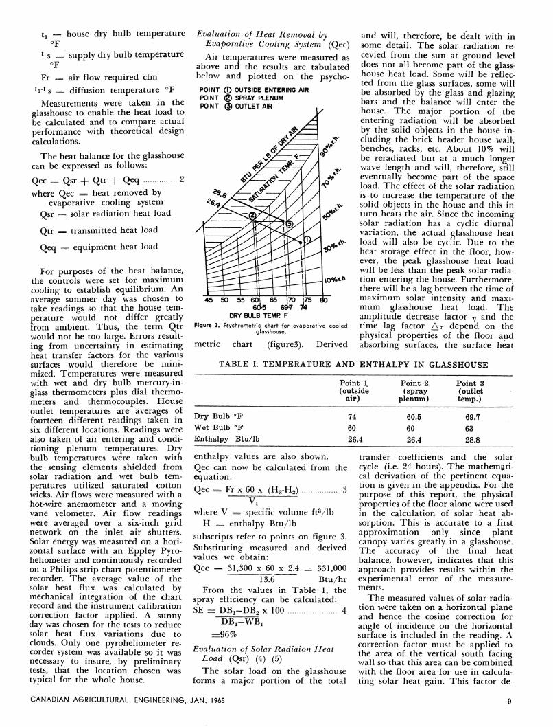
Evaluation of Heat Removal byEvaporative Cooling System (Qec)Air temperatures were measured as
above and the results are tabulatedbelow and plotted on the psycho-POINT © OUTSIDE ENTERING AIRPOINT © SPRAY PLENUMPOINT @ OUTLET AIR
45 50 55 601 65 |7D 175 806d-5 69-7 74
DRY BULB TEMP F
Figure 3. Psychrometric chart for evaporative cooledglasshouse.
metric chart (figured). Derived
and will, therefore, be dealt with insome detail. The solar radiation re-cevied from the sun at ground leveldoes not all become part of the glasshouse heat load. Some will be reflected from the glass surfaces, some willbe absorbed by the glass and glazingbars and the balance will enter thehouse. The major portion of theentering radiation will be absorbedby the solid objects in the house including the brick header house wall,benches, racks, etc. About 10% willbe reradiated but at a much longerwave length and will, therefore, stilleventually become part of the spaceload. The effect of the solar radiationis to increase the temperature of thesolid objects in the house and this inturn heats the air. Since the incomingsolar radiation has a cyclic diurnalvariation, the actual glasshouse heatload will also be cyclic. Due to theheat storage effect in the floor, however, the peak glasshouse heat loadwill be less than the peak solar radiation entering the house. Furthermore,there will be a lag between the time ofmaximum solar intensity and maximum glasshouse heat load. Theamplitude decrease factor rj and thetime lag factor At depend on thephysical properties of the floor andabsorbing surfaces, the surface heat
TABLE I. TEMPERATURE AND ENTHALPY IN GLASSHOUSE
Point 1(outside
air)
Point 2(spray
plenum)
Point 3(outlettemp.)
Dry Bulb °F
Wet Bulb °F
Enthalpy Btu/lb
74
60
26.4
60.5
60
26.4
69.7
63
28.8
enthalpy values are also shown.Qec can now be calculated from theequation:
Qec = Fr x 60 x (H3-H2) 3~V\
where V = specific volume ft3/lbH = enthalpy Btu/lb
subscripts refer to points on figure 3.Substituting measured and derivedvalues we obtain:
Qec = 31,300 x 60 x 2.4 = 331,0001376 Btu/hr
From the values in Table 1, thespray efficiency can be calculated:SE = DB^DBo x 100 4
DBx-WB!
=96%
Evaluation of Solar Radiaion HeatLoad (Qsr) (4) (5)
The solar load on the glasshouseforms a major portion of the total
transfer coefficients and the solar
cycle (i.e. 24 hours). The mathematical derivation of the pertinent equation is given in the appendix. For thepurpose of this report, the physicalproperties of the floor alone were usedin the calculation of solar heat ab
sorption. This is accurate to a firstapproximation only since plantcanopy varies greatly in a glasshouse.The accuracy of the final heatbalance, however, indicates that thisapproach provides results within theexperimental error of the measurements.
The measured values of solar radia
tion were taken on a horizontal planeand hence the cosine correction for
angle of incidence on the horizontalsurface is included in the reading. Acorrection factor must be applied tothe area of the vertical south facingwall so that this area can be combined
with the floor area for use in calculating solar heat gain. This factor de-
CANADIAN AGRICULTURAL ENGINEERING, JAN. 1965
pends on the values of the solar altitude and azimuth at the time andplace of the radiation measurements.The value of this factor was calculatedfrom:
Kv = cos a cos z/sin a 5where Kv = area correction factor forsouth facing wall
a = solar altitude degreesz = solar azimuth degrees
Values of a and z were taken fromtables (8). Kv works out to 0.68 andtherefore the total effective area touse in the heat transfer equation is:
Ah (EFF) = Ah -f 0.68 Av 6where Ah (EFF) is the effective equivalent total horizontal area
Ah is the actual horizontal area
Av is the actual area of the headerhouse wall
If the solar radiation measurementsare taken on a horizontal plane, thetotal glasshouse heat load is given by:
Qsr = qsr Ah (EFF) 7where qsr is evaluated from equa
tion 10 in the appendix.Substituting measured and calculatedvalues yields
Qsr = 344,000 Btu/hr. x
A further refinement of the solar heatgain could be made by calculating theload on the floor area over the plenumwithout any amplitude reductionfactor since no storage effect occurs inthis portion of the floor area. Theeffect on the final heat balance wascalculated to be only a few percentand is, therefore, omitted for the sakeof simplicity.Evaluation of the Transmitted Heat
Gains (Qtr)Qtr is the sum of the transmitted
heat gains through the various portions of the glasshouse and can bepositive or negative depending on thedirection of the temperature difference. The results are given by:
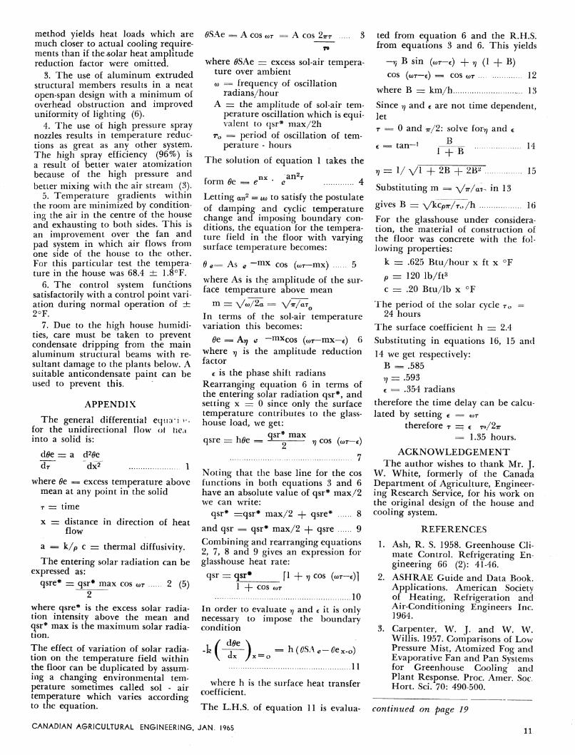
Qtr = SUi Ai (to-ti) 8and are tabulated below.
TABLE II. GLASSHOUSE TRANSMITTED HEAT GAINS
Evaluation of Equipment Heat Load(Qeq)
This is the last term in equation 2and consists of the heat gain due toelectrical equipment. Since the systemwas set lor maximum cooling, the onlysignificant heat load was due to thelour 32-inch vaneaxial fan motors,These are operated on 550 volt, threephase current and the total heatgenerated by the four fans is given by:
Qeq = 4 x 3.413 x V^*EI 9where E = Line to line voltage-volts
I = Average line current-amperes3.413 = Conversion factor-watts to
Btu/hr
a/3 = Voltage phase angle compensation factor.
Substituting average measured valueslor E and I:
Oeq = 4 x 3.413 x 1.732 x 530 x"3.03 = 38,000 Btu/hr.
Substituting calculated values of Qec,Qsr, Qtr and Qeq from equations 3,7, 8 and 9 in equation 2:
L.H.S. = 331,000 Btu/hr
R.H.S. = 344,000 - 30,100 +
38,000 = 351,900 Btu/hr. This indicates a heat balance within 7%.
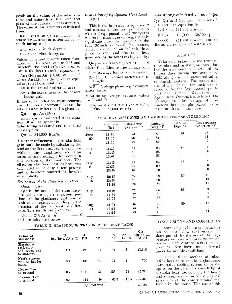
RESULTS
Tabulated below are the temperatures obtained in the glasshouse during the maximum of several of thehottest days during the summer of
' 1962, along with the measured valuesof outside ambient. For comparison,the official "high" lor each day asreported by the Agrometerology Department, Canada Department of'Agriculture, Ottawa, is also listed. Thereadings are the average of nineshielded thermocouples placed in strategic locations in the house.
TABLE III. GLASSHOUSE AND AMBIENT TEMPERATURES 1962
Date
June
29
July4
July8
Aug.29
Aug.30
Aug.31
sun time(hr)
11:00
12:05
12:30
11:25
11:45
13:00
11:45
12:20
13:35
12:45
13:35
14:10
14:00
14:30
15:05
12:05
13:15
14:15
Glasshouseaverage °F
AmbientTemp °F
74 89
76 87
77 84
74 83
72 84
72 83
84 91
82 90
82 90
78 89
77 90
78 89
77 85
77 86
77 85
80 90
80 89
79 90
Officialhigh °F
81
93
85
85
89
Temperaturereduction °F
15
11
7
9
12
11
11
13
11
8
9
8
10
9
11
Section ofGlasshouse
U ABtu/hr x ft2 x °F Ft2
Qtrto ti At = Btu/hr =°F °F to—ti UA At
CONCLUSIONS AND COMMENTS
1. Summer glasshouse temperaturescan be kept below 80°F except forshort periods by the use of the highpressure evaporative spray system described. Temperature reductions asgreat as 15°F have been achievedunder favourable conditions.
2. The outlined method of calculating heat gains enables a glasshouseevaporative cooling system to be designed on the basis of a knowledge ofthe solar heat rate entering the houseand an approximation of the physicalproperties of the constructional materials in the house. The use of this
Glasshouseroof, sidesand south endto ambient
North plenumwall to headerhouse
House floorto ground
Plenum floorto ground
10
1.1 3827 74 69 21,000
0.4 437 70 74 —700
0.4 1531 50 128 —78 —47,800
0.4 613 50 60.5 —10.5 —2,600
Qtr net total —30,100
CANADIAN AGRICULTURAL ENGINEERING, JAN. 1965
<9SAe == A cos wr = A cos 2tj
where 0SAe = excess sol-air temperature over ambient
o> = frequency of oscillationradians/hour
A = the amplitude of sol-air temperature oscillation which is equivalent to qsr* max/2h
rQ = period of oscillation of temperature - hours
The solution of equation 1 takes the
r A nx, an2T Aform Oe = e e 4
Letting ar? = «o to satisfy the postulateof damping and cyclic temperaturechange and imposing boundary conditions, the equation for the temperature field in the floor with varyingsurface temperature becomes:
6 e= As e ~mx cos (wr-mx) 5
where As is the amplitude of the surface temperature above mean
m = \/to/2a = vVaT0In terms of the sol-air temperaturevariation this becomes:
Oe = A^ e —mxcos (wr-mx-f) 6where rj is the amplitude reductionfactor
c is the phase shift radiansRearranging equation 6 in terms ofthe entering solar radiation qsr*, andsetting x = 0 since only the surfacetemperature contributes to the glasshouse load, we get:
, . qsr* maxqsre = h0e = -±—- v cos (a>T-e)
Noting that the base line for the cosfunctions in both equations 3 and 6have an absolute value of qsr* max/2we can write:
qsr* =qsr* max/2 -f- qsre* 8
and qsr = qsr* max/2 -|- qsre 9Combining and rearranging equations2, 7, 8 and 9 gives an expression forglasshouse heat rate:
qsr zzz qsr* fl -f rj COS (wr-e)]1 -\- COS ior
10
In order to evaluate 77 and e it is onlynecessary to impose the boundarycondition
-h(~A =h(CSAe-y dx /x — o
£ex-o)
11
where h is the surface heat transfercoefficient.
ted from equation 6 and the R.H.S.from equations 3 and 6. This yields
-rj B Sin (cor-c) + v (1 + B)COS (o>T—e) = COS wt 12
where B = km/h 13
Since rj and c are not time dependent,let
r == 0 and tt/2: solve for^ and €
€= tan~1 Hfb 14v zzz 1/ VI + 2B + 2B* 15
Substituting m = yV/a7- in 13
gives B = ^/kcpir/ro/h 16
For the glasshouse under consideration, the material of construction ofthe floor was concrete with the following properties:
k = .625 Btu/hour x ft x °F
p zzz 120 lb/ft3
c = .20 Btu/lb x °F
The period of the solar cycle To =24 hours
The surface coefficient h = 2.4
Substituting in equations 16, 15 and
14 we get respectively:B = .585
v; = .593€ = .354 radians
therefore the time delay can be calculated by setting € = <or
therefore T = c to/2tt= 1.35 hours.
ACKNOWLEDGEMENT
The author wishes to thank Mr. J.W. White, formerly of the CanadaDepartment of Agriculture, Engineering Research Service, for his work onthe original design of the house andcooling system.
REFERENCES
1. Ash, R. S. 1958. Greenhouse Climate Control. Refrigerating Engineering 66 (2): 41-46.
2. ASHRAE Guide and Data Book.Applications. American Societyof Heating, Refrigeration andAir-Conditioning Engineers Inc.1964.
3. Carpenter, W. J. and W. W.Willis. 1957. Comparisons of LowPressure Mist, Atomized Fog andEvaporative Fan and Pan Systemsfor Greenhouse Cooling andPlant Response. Proc. Amer. Soc.Hort. Sci. 70: 490-500.
method yields heat loads which aremuch closer to actual cooling requirements than if the^solar heat amplitudereduction factor were omitted.
3. The use of aluminum extrudedstructural members results in a neatopen-span design with a minimum ofoverhead obstruction and improveduniformity of lighting (6).
4. The use of high pressure spraynozzles results in temperature reductions as great as any other system.The high spray efficiency (96%) isa result of better water atomizationbecause of the high pressure andbetter mixing with the air stream (3).
5. Temperature gradients withinthe room are minimized by conditioning the air in the centre of the houseand exhausting to both sides. This isan improvement over the fan andpad system in which air flows fromone side of the house to the other.For this particular test the temperature in the house was 68.4 ± 1.8°F.
6. The control system functionssatisfactorily with a control point variation during normal operation of ±:2°F.
7. Due to the high house humidities, care must be taken to preventcondensate dripping from the mainaluminum structural beams with re
sultant damage to the plants below. Asuitable anticondensate paint can beused to prevent this.
APPENDIX
The general differentia! eqiuriv,for the unidirectional flow of tieiinto a solid is:
dfle = a d20e
d7" "dx2" 1
where Oe = excess temperature abovemean at any point in the solid
r = time
x zzz distance in direction of heatflow
a = k/p c = thermal diffusivity.
The entering solar radiation can beexpressed as:
qsre* = qsr* max cos wr 2 (5)2
where qsre* is the excess solar radiation intensity above the mean andqsr* max is the maximum solar radiation.
The effect of variation of solar radiation on the temperature field withinthe floor can be duplicated by assuming a changing environmental temperature sometimes called sol - airtemperature which varies accordingto the equation. The L.H.S. of equation 11 is evalua- continued on page 19
CANADIAN AGRICULTURAL ENGINEERING, JAN. 196511

TEST RESULTS USING EPOXY WITH FIBREGLASS REINFORCEMENT
Ultimate Load
laminations) 1650 lbslaminations and Fabric cloth) 2150 lbslaminations and Woven Roving) 2460 lbslaminations and Roving) 2700 lbslaminations) 1640 poundslaminations and Woven Roving) 2140 poundslamination and Roving) 2280 pounds
Material
Rectangular Timber (5Section Timber (5(Douglas Timber (5Fir) Timber (5
Arch Timber (6
Construction Timber (6
(White Pine) Timber (6
NOTE: Cloth was not used in this test due to difficulty in fabricating the arch.
The resin and fibreglass used in reinforcing timber beams are materialswhich are resistant to rot, insect infestation, and are not effected by acidsnormally found in and around agricultural structures. They are materialsthat are readily available and easilyapplied.
There should be additional research
carried out in this field, since the potential is excellent in the farm struc
tures area.
DOUGLAS FIR—FIBREGLASS AND RESIN SPRAYED WITH PATTERSON
GUN (DIRECTION PARALLEL TO GRAIN)
Deflection—0.590 inches Ultimate Load—3130 pounds
(DIRECTION PERPENDICULAR TO GRAIN)Deflection—0.830 inches Ultimate Load—3130 pounds
Figure 8. Arch with roving reinforcement and EpoxyResin.
Subsequent tests were carried outon the strength properties providedby wrapping the exterior of a solidtimber beam and applying a load toultimate failure of the beam (figure9). In this case, the ultimate for the
Figure 9. Timber beam wrapped with pre-impregnatedfibreglass.
wrapped beam was 3260 pounds, ascompared with 2000 pounds for anunwrapped specimen. The 39 per centincrease in load carrying ability morethan compensates for the materialused in the wrapping process and,moreover, the beam will still supporta load even though the ultimate hasbeen attained. This factor is onewhich should not be overlooked in
design, since adequate warning willbe given before complete destructionof a structure occurs.
A test was carried out at NaugatukChemicals in Elmira, Ontario, usingthe Patterson Spray Gun to coat oneside of a Douglas Fir member 8 incheswide and y4 inches thick. This member was subsequently used as a partof a laminated beam and tested for
ultimate load and deflection. Thecoatings were applied in the direction
of the grain in one specimen and perpendicular to the grain in anotherspecimen.
The theoretical loading for a beamof this type is 474 pounds with an allowable stress of 1800 psi.
CONCLUSIONS
It is quite practical to reinforcetimber beams with fibreglass and resinwith little increase in the thickness ofthe members. Fibreglass mat, cloth,and sirands can all be used lor rein
forcement, but the stands providethe greatest tensile strength if care istaken when applying the strands tothe surface of the material to which itis to be bonded. Erittleness in theresin must be avoided if completeuniformity in the joint is to be retained. Setting time of the epoxy resin isvariable depending on the type ofresin used, but 30 minutes setting timewill allow adequate time for goodconstruction of the member in mostinstances.
Fibreglass wrapped on the outsideof a solid or laminated timber beam
increases the ultimate strength of themember appreciably. Even when failure occurs, the fibreglass has enoughretentive strength to support loadsand may be an asset from a safetypoint of view.
Pre-impregnated fibreglass does notstand up under test, since materialsused in this program have an affinityfor moisture and would not be useful
in agricultural structures.
CANADIAN AGRICULTURAL ENGINEERING, JAN. 1965
ACKNOWLEDGEMENTS
This paper was made possiblethrough the co-operation of the following who gave freely of their experience in reinforced plastics, andsupplied material for the tests:
Canadian General Electric Company Limited, Guelph, Ontario.
Naugatuk Chemicals CompanyLimited, Elmira, Ontario.
Miss Helen Tucker, Student Assistant, Ontario Agricultural College.
Mr. D. P. Naraine, Student Assistant, Ontario Agricultural College.
GLASSHOUSE DESIGN
continued from page 11
4. Jacob, M. 1959. Heat Transfer.Volume 1: 292-304. John Wiley &Sons Inc. Seventh Printing.
5. Kowalczewski, J. J. 1962. AirConditioning of Glasshouses inthe CSIRO Phytotron. J. Inst.Eng. Austr. 34 (3): 71-79.'
6. Morris, L. G. 1962. Some RecentAdvances in the Control of PlantEnvironment in Glasshouses. Presentation at the Symposium onEngineering Aspects of Environment control for plant growth.Melbourne, Australia.
7. Scott, K. R. and W. Kalbfleisch.1963. Plant Growth Building withEvaporative Cooling. J. Can. Soc.Agr. Eng. 5: 32-33, 40.
8. Tables of Computed Altitude andAzimuth. U.S. Navy Hydrogra-phic Office Pub. No. 214, Volume5. 1958.
1!)