Embed Size (px)
Citation preview
AbstractmdashIn the period of several last decades glass is used not
only as a transparent filling of building openings but also as the
statically and dynamically loaded civil engineering structural
component Structural glass is brittle material without elastic or
elasto-plastic behaviour so the missing pliability of the material
cannot help to decrease the influence of the local stresses
concentration Also the deformations of the slab structures can
significantly exceed the slab thickness so it is necessary to apply the
theory of the large deflections ie geometrically nonlinear theory of
the 2nd order of thin slabs Thus the design of load-carrying
structures made of structural glass requires diametrically different
approaches than in the case of conventional building materials The
paper presents some examples of the arrangement of load-carrying
structural systems and inclusion of the glass components into the
buildings structural details and used basic materials Significant
parts of the verification of the reliability of structural glass systems
are experiments and loading tests realized for the real load and
boundary conditions and for the real composition of used materials
corresponding to the verified structure In the paper basic typical
failure modes of the components made of float glass and laminated
float or tempered glass with intermediate foil Also the examples of
realized buildings using load-carrying components of structural glass
are mentioned respectively also their damage and crash
KeywordsmdashStructural glass float glass tempered glass
material property building civil engineering failure
I INTRODUCTION
HE basic classic materials of building load-carrying
structures (masonry concrete steel timber) are more
significantly complemented (in the last period) by structural
glass which is not only traditional filling of smaller window
openings where their dimensions (thickness) arising from the
long term practical experience has not been usually verified
by the static assessment Emerging trends in the architectonic
creation of the buildings requiring large glazed areas of civil
structures but ndash on the other hand ndash also the possibilities of
their realization related to the development of the production
technology of the large scaled glass components bring new
This work was supported by the Ministry of Education Youth and Sports
of the Czech Republic under the research projects LO1408 ldquoAdMaS UP ndash
Advanced Materials Structures and Technologiesrdquo within the ldquoNational
Sustainability Programme Irdquo
Marcela Karmaziacutenovaacute Professor of Civil Engineering is the head of the
Department of Metal and Timber Structure of the Faculty of Civil Engineering
at the Brno University of Technology Veveřiacute St 33195 602 00 Brno Czech
Republic (corresponding author to provide phone +420 541 147 310 fax
+420 549 245 212 e-mail karmazinovam fcevutbrcz)
Jindrich Melcher Professor of Civil Engineering is the head of the Pooled
Testing Room for Load-Carrying Structures of the Department of Metal and
Timber Structure Faculty of Civil Engineering Brno University of
Technology (e-mail melcherj fcevutbrcz)
challenges for the industry of the glass production as well as
for structural engineers
Similarly as traditionally in the case of load-carrying civil
structures glass requires ndash in dependence on the support type
load intensity and material properties ndash the verification of the
reliability durability and effectiveness as it is in civil
engineering practice necessary in the case of other structural
materials
For the reasons mentioned above the attention is paid to the
research realization and development of methods for the
design and resistance of the load-carrying structures made of
structural glass over the world For further development of
the usage of load-carrying structural glass in civil engineering
structures it is important to develop the new technologies and
procedures of the glass production which are ensured by
many significant producers of the diverse assortment of glass
components as well as respective supply companies
II MATERIALS AND COMPOSITION OF STRUCTURAL GLASS
ELEMENTS
A Annealed Glass Float Glass
The basic type of building glass which can be modified and
treated by tempering staining sandblasting and cutting is
clear float glass The input raw material for its production is
silica in the form of sand soda in the form of carbonate and
sulphate and limestone as a stabilizer Flat clear glass is an
input raw material for the wide range of the usage of glass in
building structures (interiors and claddings of buildings) The
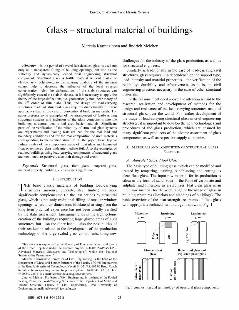
basic overview of the heat-strength treatments of float glass
with appropriate technical terminology is shown in Fig 1
Fig 1 composition and terminology of structural glass components
Glass ndash structural material of buildings
Marcela Karmaziacutenovaacute and Jindrich Melcher
T
Energy Environment and Material Science
ISBN 978-1-61804-352-8 23
B Fully Tempered Glass Toughened Glass
The increasing of the mechanical resistance of float glass
can be reached using the technology of heat-toughening
(tempering) that means glass is heated to the specific
temperature (about 650 degC) and subsequently it is cooled by
the sharp airflow Due to the cooling inside the structure of
heat-strengthened glass the tensile stress occurs while on the
surface the compression stress occurs
Thus the physical properties from the viewpoint of the
strength are significantly changed In the case of breaking
glass will break into small pieces so the risks of personal
injury and property damage are minimized The new
distribution of the stress in toughened glass affects the
essential change of glass properties
Fully-tempered glass will obtain the resistance to the strike
and further the flexural strength and thermal resistance up to
200 degC will be increased Thanks to these properties this glass
is classified as safety glass Glass must be finally machined
(drilling holes grinding edges etc) before tempering because
its further machining after toughening is not already possible
The usage of heat-toughened glass requires significant
attention from the viewpoint of the elimination of safety risks
associated with keeping technological limits of dimensions
and shape of the component initial deformations and failures
details of bearing on the support structure and so on The
special problem can also be spontaneous explosion of heat-
toughened glass
The problems mentioned above are in detail discussed for
example in the sources [4] and [5] which define the basic
causes of the failures of glass
- the breakage of glass due to the temperature shock
- the failure of glass due to the assembly mistake
- the failure of glass caused by the poor machining
- the condensation in the interspace of insulating double
glass or triple glass
- the spontaneous explosion of heat-toughened glass
In the cases when the risk of the spontaneous breakage of
glass with nickel sulphide (NiS) inclusions is inadmissible it
is recommended to use so-called ldquoheat-soakrdquo test of already
heat-treated glass panes So it is practically avoided the usage
of glass which can crack without previous warning due to
anomalies caused in the tempering process
C Heat Strengthened Glass Partly Toughened Glass
The next type of heat-strengthened glass is semi-hardened
partly toughened glass Its mechanical properties of soda-
lime-silica glass do not change during the progressive heating
at least up to 200 degC and they are not influenced by the
temperatures below freezing
In the production process glass is subjected to the special
heat treatment which is different from usual heat toughening
The temperature of glass heating and the time of the whole
treatment process are different Then the result is glass with
increased mechanical resistance (compared with float glass)
and in the case of breakage the pane is broken to the larger
pieces The resistance to the heat stress is also higher The
advantage is that this type of glass has no nickel sulphide
inclusions (NiS) and resists to the temperature difference of
up 100 degC
D Laminated Safety Glass
Laminated safety glass is composed of two or more panes
of tempered or heat-strengthened glass with the usage of
intermediate foil inserted in autoclave at the temperature of
about 140 degC and the pressure of 08 MPa Most often used
intermediate foils are polyvinyl butyral (PVB) or ethylene
vinyl acetate (EVA) foils The thickness of the foil is
according to the type 038 mm or 076 mm
In the case of breakage safety glass remains glued to the
foil and the personal injury and property damage are avoided
In the cases when one of glass is not damaged the wholeness
of glass pane is maintained
Safety glass has the application there where it is required
avoiding injury to protect against burglary and firearms and
noise protection The combination of laminated heat-
toughened glass is also used for walkable glass slabs
Safety laminated glass with acoustic effect uses PVB foil
and reaches improved characteristics for avoiding the noise
spreading The properties of this glass depend on the specific
composition and combination of the glass panes and foils The
maximal value of the sound attenuation is 45 dB
III PRINCIPLES OF DESIGN OF STRUCTURAL GLASS
COMPONENTS
The default illustrative comparison of the static behaviour
of glass steel and concrete is evident from stress-strain
diagrams for these materials drawn in Fig 2 The course of
those diagrams indicates the response of the relevant material
to the load
It is evident that structural glass is ideal elastic brittle
material without elastic-plastic or plastic behaviour and thus
pliability (ductility) of the material cannot decrease the
influence of the concentration of local stresses in the case of
intensive loading
From the viewpoint of the design of structural details and
connections it is necessary to eliminate the direct contact of
glass and supporting steel structure for example using plastic
washers inserts eventually sealants or backed silicone
profiles which allow to exclude failures arising from the
rigidity of locally loaded glass component
In addition the deflection of slab structures ndash particularly in
the case of one-layer panes ndash can significantly exceed the slab
thickness so for the static analysis it is necessary to utilize the
theory of the large deflections ie geometrically nonlinear 2nd
order theory of thin slabs instead of the classic Kirhoffrsquos
theory of thick slabs In this case the flexural effects are
supplemented by the membrane components of the load in the
slab plane
The principles of the design of the load-carrying structures
with the application of structural glass require markedly
different approaches than in the case conventional building
materials
Energy Environment and Material Science
ISBN 978-1-61804-352-8 24
(a)
(b)
(c)
Fig 2 characteristic stress-strain diagrams of (a) glass (b) steel and
(c) concrete
Basic material mechanical and physical characteristics of
soda-lime-silica glass are mentioned in Table 1
Table 1 characteristic values of soda-lime-silica glass
Quantity Symbol Value and unit
Density (specific weight) ρ 2 500 kgmiddotm-3
Youngrsquos modulus of elasticity E 70 000 Nmiddotmm-2
Shear modulus of elasticity G 30 000 Nmiddotmm-2
Poissonrsquos coefficient μ 023
Coefficient of thermal expansion α 9middot10-6 K-1
The philosophy methodology and procedures of the design
of load-carrying structures for the basic materials (concrete
masonry steel timber steel-concrete) are in detail elaborated
and introduced in the unified European Standards
(Eurocodes)
In general for structural glass all the principles defined in
EN 1990 ndash Eurocode Basis of Structural Design and EN 1991
ndash Eurocode 1 Loading Actions where the principles for the
loads by snow wind dead load live load etc are mentioned
are valid
Normative uniform European document allowing the static
design of load-carrying systems with the usage of structural
glass is however in the stage of the proposal and it is not
definitively approved Therefore in this paper informative
data only following the concept of selected procedures for the
design of building structures with the usage of structural glass
are mentioned in the meaning of prepared normative
documents arising from the methodology of limit states
A Strengths of Structural Glass
The basic characteristic strength of float glass fkg as a basic
material property can be given as the value of
fkg = 40 Nmm2 (1)
The characteristic strength fk of the component made of
structural glass can be determined according to the formula
fRk = kmod middot ksp middot fkg (2)
where kmod is the factor of the type and duration of the load
which reaches the values in the range from 029 to
100
ksp is the factor of the type of the surface of glass
component which reaches the values in the range from
032 to 055
The basic characteristic strength of heat-strengthened glass
can be given as the value of
fkg = 70 Nmm2 (3)
The basic characteristic strength of heat-toughened glass
can be given as the value of
fkg = 120 Nmm2 (4)
The characteristic strength of the components made of
structural heat-treated glass can be in principal determined
according to the same formula as for float glass ie formula
(2) where similarly as in the case of float glass kmod is the
factor of the type and duration of the load and ksp is the factor
of the type of the surface of glass component
B Resistance of Structural Glass Load-Carrying Systems
The verification of the resistance of load-carrying system
with the usage of structural glass for the ultimate limit state
Energy Environment and Material Science
ISBN 978-1-61804-352-8 25
can be performed according to the design reliability condition
Ed le Rd (5)
where Ed is the design value of the load effect
Rd is the design value of the resistance of the structural
component or system
The design strength fRd of the structural glass component can
be determined according to the formula
fRd = fRk γM (6)
where the value of the reliability safety factor γM is
recommended to take as
γM = 12 (7)
From the viewpoint of the serviceability limit state the
permissible values of the deflections δlim are given as (up to)
δlim = L 100 (8)
where L is the span of the component between supported
edges
All the indicated design factors material characteristics and
reliability coefficients will be more in detail defined after the
approval of the prepared European document EN 13474 Glass
in Civil Engineering
In conclusion of this paragraph it should be noted that it is
not recommended to use and design the thickness of one layer
of load-carrying structural glass less than 3 mm and greater
than 25 mm
IV SELECTED EXAMPLES OF REALIZATIONS AND STUDIES
The development of the use of the building load-carrying
systems with the application of structural glass is further
indicated by the selection of illustrative examples of buildings
and project studies realized over the world but also in the
Czech Republic
Fig 3 stairs in Audio-Video Shopping Center New York
The glass stair suitably integrated to the interior of the
Audio-Video Centre in San Francisco is shown in Fig 3
(photo J Melcher) Glass does not prevent the vista to the
internal space of the building The stair grades as well as the
vertical supporting structure stiffened by supporting
transverse ribs are designed and made of glass Transverse
stiffening ribs are necessary with respect to the insurance of
the resistance of the high slender wall subjected to the vertical
compression load
Fig 4 Juilliard School in Lincoln Center New York
The structures in the areas of Lincoln Centre in New York
stiffened by twisted rope are illustrated in Fig 4 Partition
peripheral or external walls or eventually railing fillings
without significant effects of the basic loadings (vertical load
wind and so on) shall be assessed according to the technical
document ČSN EN 12600 Glass in Civil Engineering ndash
Shuttle Test ndash Method of Impact Test (ČNI Prague 2003) and
ČSN 74 3305 Protective railings (ČNI Prague 2008)
High glazed peripheral building walls ndash with respect to the
significant effects of the wind load (compression or sucking) ndash
shall be necessarily stiffened by the steel load-carrying
structure which create the support system of peripheral glass
cladding
(a) (b)
Fig 5 (a) wall in Waterloo Station London (b) hall of International
Forum Tokyo
Energy Environment and Material Science
ISBN 978-1-61804-352-8 26
In Fig 5 (a) (photo J Melcher) the structure of the glazed
wall in the area of Waterloo Station in London with the steel
support structure which is created by the truss system with
ties and struts placed both outside and inside the building is
shown In Fig 5 (b) (photo J Melcher) the structure of the
glazed wall of so-called Glass Hall in the areas of the
International Forum in Tokyo with steel support structure
created by the truss system with ties and struts placed inside
the building is shown
From the shots mentioned the arrangement of the relevant
structural system is evident and mentioned examples indicate
large diversity of the composition and structural design of
load-carrying systems with the usage of structural glass
The illustration of the successful usage of structural glass in
the Czech Republic is the oblique faccedilade of the store Sykora
Home Prague [6] in Fig 6 The wall of the faccedilade is along the
top line inclined from the vertical plane The laminated glass
panels are through the targets anchored to the steel load-
carrying structure created by lattice crosspieces which are
supported by steel columns inclined in parallel with the
faccedilade The lattice tube crosspieces are supported by the
system of rectifiable parallel ties DETAN
Fig 6 structure of oblique faccedilade of Sykora Home building Prague
The example of the usage of structural glass for the roofing
of the platform of bus station near the railway station Ostrava
ndash Svinov is shown in Fig 7 The work has been ensured by
the company METALPROGRES Inc Tetčice and on the base
of this the experimental programme [7] [9] of the verification
of load-carrying capacity and deformations of the panels made
of structural glass corresponding the real composition and
supporting of test specimens has been realized Relevant
loading tests are more in detail mentioned below in the
chapter 5
The roofing component made of two-layer tempered glass
with intermediate foil showed the possibility of the fall of
glass slab to the covered space in the case of the failure
around metal targets With regards to otherwise favourable
deformation and strength characteristics of proposed
composition of roofing panel it can be effective to eliminate
this problem by supplementary technical modification which
will exclude the fall of the failed specimens The proposed
modification lies in the inserting protective rope (see Fig 7)
under glass slab The rope is anchored to the shackles in the
axis of the bolts of circle connecting plates and it is lead
diagonally and further along the line connecting four support
nodes of glass slab The utilized steel rope had the diameter of
5 mm in general it is enough to design the rope according to
the corresponding self weight and the number of the hangings
The failed pane composed of laminated tempered glass is
detained by the protective rope it remains undivided thanks to
the stiffening effect of the foil and in addition it is capable of
transport and manipulation when replacing
Fig 7 roofing of platform of bus station Ostrava - Svinov
In the period of the last years the usage of the large-scale
glazed faccedilades of buildings has been significantly spread
Their necessary stiffening in relation to the adverse effects of
compression and sucking of the wind is ensured by the
transverse glass ribs so-called fins which are inserted in
parallel in the certain distances into the faccedilade system
Various possibilities of the composition of the glass walls
of the mentioned type are documented by the examples of the
realizations over the world but also in the Czech Republic
(a) (b)
Fig 8 (a) South Bank University London (b) Holiday Inn Paris
Energy Environment and Material Science
ISBN 978-1-61804-352-8 27
Fig 8 (a) shows the shot of the structural glass wall
stiffened by transverse glass ribs in the building of London
South Bank University Another example of the similar
solution of the restaurant glass wall in Holiday Inn Hotel in
Paris is shown in Fig 8 (b) (photo J Melcher) Further the
solution realized in Burj Al Arab Hotel in Dubai is illustrated
in Fig 9 and finally the glass wall in the building of Harbour
Grand Kowloon Hotel in Hong Kong is in Fig 10 (photo J
Melcher)
Fig 9 Burj Al Arab Hotel Dubai
Fig 10 Harbour Grand Kowloon Hotel Hong Kong
From the structures of the similar type realized in the Czech
Republic it is documented the glass faccedilade stiffened by
transverse ribs which lines the stairs tower of the new
building of the Faculty of Civil Engineering of Technical
University of Ostrava as indicated in Fig 11 (photo J
Melcher) This work was tasked by the company TOLZA
Ltd Brno The tests of the connection of the transverse rib to
the faccedilade of the type of ldquometal plate ndash glassrdquo with the usage
of two-component silicon sealant have been performed as
illustrated in Fig 12
The specimens with surface treated by powder-coated Al-
profile with coating represented by polyester thermoset
powder of PE GREY RAL7015 GLOSS or eventually
powder coating of Interpol D1036 Lesk 85 showed the
satisfactory adhesion of sealant to metal and glass and the
failure always occurred on the shear area going through
silicon part of the specimen ndash for more see eg [8]
Fig 11 structural glass faccedilade stiffened by transverse ribs ndash Faculty
of Civil Engineering Technical University of Ostrava
Fig 12 tests of sealant for glass faccedilade for Faculty of Civil
Engineering Technical University of Ostrava
The special structural group with the usage of exposed
load-carrying glass components are large aquariums in the
areas of ZOOs or social centres
Fig 13 aquarium on area of exposition of ZOO Park
Energy Environment and Material Science
ISBN 978-1-61804-352-8 28
The example of the aquarium in the interior of the building
of ZOO Park is shown in Fig 13 Probably due to the
imperfect structural solution of the spot support of the load-
carrying structure near the edge of the glass wall the
aquarium has been failed when filling by water as evident
from Fig 14 (photo J Melcher) The vertical wall of the
aquarium composed of laminated glass with the thickness of
3 x 8 = 24 mm with inserted intermediate PVB foil had the
width of 4 800 mm and the height of 2 800 mm It was
divided by vertical gaps at the thirds of the length filled by
silicon sealant The illustrative utilization of ANSYS software
(J Kala) for the elaboration of the expertise of the crash is
briefly shown in Fig 15
Fig 14 damage of aquarium after filling by water
Fig 15 illustrative utilization of ANSYS software for elaboration of
static assessment
In this connection it is also interesting to mention the
transparent wall of the greatest world aquarium in the
shopping centre Dubai Mall in Dubai illustrated in Fig 16
The transparent front wall has the width of 3288 m the
height of 83 m and the thickness of 750 mm The weight of
the wall is 245 614 kg Technically it is not the material
corresponding building glass although it is sometimes marked
as acrylic glass Chemically it is the transparent thermoplastic
PMMA (polymethylmethacrylate) often used as an alternative
to glass characterized by the small weight and the high
resistance to the fragmentation failure Its widening in the
practice has been introduced after 1933 year under the
trademark Plexiglass later ACRYLITEreg Lucite and Perspex
Fig 16 aquarium in shopping centre Dubai Mall
V VERIFICATION EXPERIMENTS AND STRUCTURAL GLASS
COMPONENTS TESTING
The authorsrsquo workplace ie the Department of Metal and
Timber Structures of the Faculty of Civil Engineering at Brno
University of Technology (BUT) pays long term attention to
the verification of the resistance and analysis of the actual
behaviour of load-carrying structural components and systems
composed of steel timber steel-concrete glass-fibre-concrete
glass combined structures and also composites eventually
other materials with considering the influence of their
imperfections (geometrical structural and constructional) ndash
see eg [9] [7] and [10] to [20]
This tradition which is continuously following has been
already introduced under the action of Professor Ferdinand
Lederer on the authorsrsquo workplace together with the accent to
the questions of the theory calculation methods and static and
structural design of the load-carrying components and systems
made of these materials
Fig 17 traditional method of uniform loading of planar components
Within the loading of the structural glass load-carrying
components the primary problem is the realization of the full
uniform load simulating compression or sucking of the wind
eventually snow load The loading process should allow
Energy Environment and Material Science
ISBN 978-1-61804-352-8 29
monitoring and recording the deflections and also damage of
tested specimens in the progress of increasing or decreasing
the load
It is evident that the traditional method of the loading of
the planar structural components by full uniform load using
weighed ballast gradually loaded at the tested specimen used
sometimes even at the front foreign research or university
workplaces (see Fig 17) is imperfect and unsuitable method
for the verification of the actual behaviour of the glass panes
In the testing room of the Department of Metal and Timber
Structures of the Faculty of Civil Engineering at BUT the
new efficient so-called vacuum test method allowing the
uniform loading of the planar structural components has been
developed after 1980 year Fig 18 shows one of the first
experiments of the type mentioned used for the verification
test of the resistance of glass fill of the railing of the bridge of
Vysočina at Velkeacute Meziřiacutečiacute (given by the task of A Pechal)
to the uniform load corresponding the effects of compression
or sucking of the wind
Fig 18 loading test of railing fill ndash bridge of Vysočina
Fig 19 scheme of arrangement of vacuum loading test of structural
glass planar component
The basic scheme of the arrangement of the vacuuming in
the loading test of the structural glass component is shown in
Fig 19 The component tested (a) is supported as corresponds
with the real structure for example line supports or single
support nodes or targets (c) anchored to the helping frames
similarly as in the real load-carrying system The slab
specimen supported as mentioned is installed to the separate
testing box (d) represented by the rigid peripheral timber
frame and the tested specimen together with the box are
covered by the transparent plastic foil (c) glued to the
stiffened floor of the testing room The floor must be
stiffened with regards to the significant effect of sucking in
the closed testing box
From the space closed under the transparent foil the air is
sucked and then the tested specimen is ideally uniformly
loaded by the effect of the atmospheric overpressure The
overpressure is measured by the electrical sensor with the
digital pressure gauge and in parallel for checking it is
verified using the liquid barometer The regime of the uniform
loading and reloading may be simply regulated and the load
intensity is determined measuring the overpressure between
the external environment and the space closed by foil The
illustrative shot of the real test of vacuum loading of structural
glass is in Fig 20
Fig 20 illustration of arrangement of real test of structural glass
Fig 21 failure of single-layer float glass ndash test specimen T1
Fig 22 failure of single-layer float glass ndash test specimen T1
Energy Environment and Material Science
ISBN 978-1-61804-352-8 30
Experiments verifying the actual behaviour of the glass
components allow analysing the deformations (deflections)
and the ultimate load-carrying capacity as well as the failure
mechanism in dependence on various material and structural
composition of the glass component
Fig 23 failure of laminated float glass ndash test specimens T3 T4
Fig 24 typical failure around local target support ndash specimens T3 T4
Fig 25 failure of laminated tempered glass ndash test specimens T5 T6
Fig 26 influence of safety rope on failure of specimens T5 T6
Characteristic examples of the failure of the glass
specimens tested within the research programme [7] [9] are
for the illustration indicated in figures below Failure of the
test specimen made of single-layer tempered glass (T1) is
characterized by breaking up to small fragments ndash see Fig 21
The test specimen made of laminated double-layer
tempered glass (T2) has been failed by tearing from the
supporting targets and by the subsequent falling of the whole
specimen ndash see Fig 22 The essentially different failure
mechanisms of the test specimens made of laminated float
glass (T3 T4) and laminated tempered glass with intermediate
foil (T5 T6) are evident from the shots in Figs 23 and 24 in
comparison with Figs 25 and 26
On the base of tests realized on the authorsrsquo workplace the
failure mechanism of the component made of structural glass
of different composition arrangement is indicated further It is
the wall component made of insulating triple-layer glass in the
arrangement according to Fig 27 (a) The tests have been
realized for the company GLASS EXPERTS Ltd Žlutice
(a)
(b)
Fig 27 loading test of pane made of insulating triple-layer glass (a)
composition of glass component (b) failure of glass component
On the base of the tests realized on the authorsrsquo workplace
the failure mechanism of the component made of structural
glass of different composition arrangement is indicated
further It is the wall component made of insulating triple-
layer glass in the arrangement according to Fig 27 (a) The
tests have been realized for the company GLASS EXPERTS
Ltd Žlutice
The test specimen is the wall component made of structural
float glass created by 3 parallel elements with the thickness of
3 x 6 mm the width of 700 mm and the length of 2 470 mm
which are connected by structural silicon on the longitudinal
sides The glass part of the test specimen is on the perimeter
mounted in the steel frame the basic part of which is
represented by the square hollow thin-walled cross-section
with the dimensions of 60 x 60 x 4 mm
Energy Environment and Material Science
ISBN 978-1-61804-352-8 31
The failure occurs suddenly at the initiation of the fracture
of glass due to the deformation in the area of the anchorage of
glass panes into the rigid peripheral steel frame The character
of the failure corresponds to the unfavourable arrangement of
used float glass as illustrated in Fig 27 (b)
VI EXPERIMENTAL VERIFICATION OF STIFFNESS
PARAMETERS OF STRUCTURAL GLASS
Within the loading tests of the structural glass panes
intended for the roofing bus station platform (see above) the
verification of stiffness parameters of glass has also been
performed to verify the actual values of Youngrsquos modulus of
elasticity and in the case of laminated double-layer glass the
actual values of the flexural stiffness and from these arising
the actual values of the second moments of area influenced by
the non-stiff connection between glass layers given by the
intermediate foil
According to the producer of glass plated structural
components mentioned above the value of Youngrsquos modulus
of elasticity of glass has been recommended as E = 70 GPa
but this is only generally considered value which has not been
verified by the producer Therefore before the loading tests
the experimental verification of the Youngrsquos modulus has
been performed at first In this connection as the second one
it was to verify the flexural stiffness of the test specimens with
regards to their composition (laminated glass with the
intermediate foil) and the production technology of glass
TEST T6 - M
000
010
020
030
040
050
0 5 10 15 20 25
wE [mm]
pE [
kP
a]
T6 - Mbod A
TEST T4 - M
000
010
020
030
040
050
0 5 10 15 20 25
wE [mm]
pE [
kP
a]
T4 - M bod A
TEST T2 - M
000
010
020
030
040
050
0 5 10 15 20 25
wE [mm]
pE [
kP
a]
T2 - M bod A
Fig 28 relationships ldquopE ndash wErdquo obtained directly from tests
TESTY T - M
0
01
02
03
04
05
0 5 10 15 20 25
wE [mm]
pE [
kP
a]
T2 - M T4 - M T6 - M
Fig 29 relationships for stiffness derivation
For this reason the test specimens have been supported on
the shorter opposite sides of the plate as the simply supported
structural members The theoretical span of the member was 2
294 mm The specimens have been subjected to the uniform
loading up to the load value about of 10 of the predicted
load-carrying capacity The specimens have been repeatedly
loaded and unloaded and the relationships of ldquoload ndash
deflectionrdquo ( ldquopE ndash wErdquo) have been monitored The ldquopE ndash wErdquo
relationships obtained from the tests for all test specimens are
illustrated in Fig 28 Using the regression analysis the linear
relationships have been derived (see Fig 29) From them
Youngrsquos modulus of elasticity the flexural stiffness and the
effective second moment of area can be determined (Table 2)
Table 2 stiffness parameters (per width of 1 m)
Specimen T1 T2 T5 T6 T3 T4
E Ieff [Nmm-2] 8654109 18029109 29568109
I = 112 bt3 [mm4] x) 144103 341103 667103
k (Ieff = k I) 10 0879 0879
E [GPa] 601 601 505
x) t is total thickness of layered glass (12 mm 2x8 mm 2x10 mm)
Using the relationship between the load pE and
corresponding deflection wE in the mid-span the effective
flexural stiffness EIeff1 can be derived if E is the modulus of
elasticity and Ieff1 is the effective second moment of area For
single-layer tempered glass (test specimens T1 T2) the
effective second moment of area is in the form of
Ieff1 = I = 112 (bmiddott3) thus k = Ieff I = 1 and from where the
modulus of elasticity E of tempered glass can be derived
directly Using this value of the elasticity modulus for
tempered layered glass (tempered glass of the same
mechanical properties) with intermediate foil (test specimens
T5 T6) and using the stiffness EIeff the effective second
moment of area of double-layer glass can be derived as
Ieff = k I where the coefficient k expresses the reduction of the
second moment of area I considered for the solid cross-section
with the thickness of t due to the influence of the pliability of
the foil connection Assuming that also for laminated non-
tempered glass (test specimens T3 T4) the influence of the
foil on the effective second moment of area may be expressed
by the same coefficient of the pliability k then the (at least
tentative) value of the elasticity modulus of non-tempered
glass can be derived
VII CONCLUSIONS
Structural glass is already the important part of the wide
spectrum of the materials of load-carrying structures of civil
engineering buildings over the world and also in the Czech
Republic Nevertheless the typical examples mentioned above
cannot systematically illustrate all the possibilities of the
structural composition and structural detailing from the
Energy Environment and Material Science
ISBN 978-1-61804-352-8 32
viewpoint of the usage of glass in civil engineering structures
but they can indicate the modern trends of the architectonic
creation of the buildings requiring the large glazed areas of
civil engineering structures and also the possibilities of their
realization in the connection with the development of the
production technology of the large scale glass components and
with the new challenges for the industry of the glass
production as well as for the structural engineers
The paper was focused on the significant field of the design
and realization of buildings with the application of structural
glass including the verification of the dimensions of the glass
components in relation to the material load intensity and
boundary conditions on the one hand and the verification of
the theoretical assumptions and design methods through the
experiments and loading tests taking into account the
influence of the initial imperfections of the real load-carrying
system on the other hand
The general philosophy and methodology of the static and
structural design of buildings using structural glass arises from
the similar general principles as in the case of other materials
of load-carrying structures However glass has many
fundamentally different properties that can influence its
behaviour in the structure (thermal shock failures of glass
caused by the material inhomogeneity due to the inclusions
spontaneous explosion material brittleness without elasto-
plastic or plastic behaviour and without the possibility to
decrease the influence of the concentrations of local stresses
necessity of the utilization of geometrically non-linear 2nd
order theory of thin slabs etc) This paper thus also tried at
least briefly to warn to some problems mentioned above
requiring more detailed consideration and cognition
ACKNOWLEDGEMENT
The paper has been elaborated within the research project
No LO1408 ldquoAdMaS UP ndash Advanced Materials Structures
and Technologiesrdquo supported by the Ministry of Education
Youth and Sport of the Czech Republic within the framework
of the National Sustainability Programme I
REFERENCES
[1] Š Popovič Production and processing of flat glass (Vyacuteroba a
zpracovaacuteniacute plocheacuteho skla ndash original in Czech language) Grada
Publishing as Praha 2009 ISBN 978-80-247-3154-4
[2] M Haldmann A Luible M Overend Structural Use of Glass Zurich
ETH Zurich 2008 215 pp ISBN 3-85748-119-2
[3] A Goris Bautabelen fur ingenieure mit Berechnungshinweisen und
Beispielen Koumlln Wolters Kluwer Deutchland GmbH 2008 555 pp
ISBN 978-3-8041-5236-6
[4] M Saacutezovskyacute ldquoHow to avoid the most common failures of structural
glass ndash I Partrdquo (ldquoJak předchaacutezet nejčastějšiacutem poruchaacutem stavebniacuteho skla
ndash I diacutelrdquo ndash original in Czech language) Stavebnictviacute Vol10 2010 pp
45-48 ISSN 1802-2030
[5] M Saacutezovskyacute ldquoHow to avoid the most common failures of structural
glass ndash II Partrdquo rdquo (ldquoJak předchaacutezet nejčastějšiacutem poruchaacutem stavebniacuteho
skla ndash II diacutelrdquo ndash original in Czech language) Stavebnictviacute Vol01 2011
pp 52-55 ISSN 1802-2030
[6] F Stejskal ldquoSteel structure of store building of Sykora Home Praha ndash
Vysočanyrdquo (ldquoOcelovaacute konstrukce stavby obchodniacuteho domu Sykora
Home v Praze Vysočanechrdquo ndash original in Czech Language) Stavebnictviacute
Vol 03 2010 p 9 ISSN 1802-2030
[7] J Melcher and M Karmaziacutenovaacute ldquoThe experimental verification of
actual behaviour of the glass roofing structure under uniform loading In
Proceedings of the 4th European Conference on Steel and Composite
Structures ldquoEUROSTEEL 2005rdquo Druck and Verlagshaus Mainz Gmbh
Aachen Maastricht 2005 Vol B pp 24-1 ndash 24-8 ISBN 3-86130-
812-6
[8] J Melcher and M Karmaziacutenovaacute ldquoStrength and deformational
characteristics of structural sealant in load-carrying connections of
structural glass componentsrdquo (ldquoPevnostniacute a přetvaacuterneacute charakteristiky
strukturaacutelniacuteho tmelu v nosnyacutech spojiacutech diacutelců z konstrukčniacuteho sklardquo ndash
original in Czech language) In Proceedings of the International
Conference ldquo70 years of Civil Engineering Faculty of Technical
University in Bratislavardquo STU Bratislava 2008 6 pp ISBN 978-80-
227-2979-6
[9] J Melcher and M Karmaziacutenovaacute ldquoThe design and experimental
verification of actual behaviour of the structural glass in roofing and
facade systemsrdquo In Proceedings of the 3rd International Conference on
Structural Engineering Mechanics and Computation ldquoSEMC 2010rdquo
held in Cape Town Millpress Rotterdam 2007 pp 657-658 ISBN
978-90-5966-054-0
[10] J Melcher ldquoBehaviour of Thin-Walled Corrugated Sheets and
Restrained Beamsrdquo In Proceedings of the IABSE Colloquium Stockholm
1986 Thin-Walled Metal Structures in Buildings IABSE ETH ndash
Houmlnggerberg Zuumlrich 1986 pp 199-206
[11] J Melcher ldquoFull-Scale Testing of Steel and Timber Structuresrdquo In
Proceedings of International Seminar Structural Assessment ndash The
role of large and full-scale testing (K S Virdi and others Ed) EampFN
SPON London 1997 pp 301ndash308 ISBN 0 419 22490 4
[12] J Melcher and M Karmaziacutenovaacute ldquoGlass and metal ndash modern materials of
civil engineering buildingsrdquo (ldquoSklo a kov ndash soudobeacute materiaacutely
občanskyacutech stavebrdquo ndash original in Czech language) In Proceedings of
the National Conference Steel Structures Hustopeče 2001 Czech
Society for Steel Structures
[13] J Melcher and M Karmaziacutenovaacute ldquoOn problems of the design of load-
carrying systems made of structural glassrdquo (ldquoK probleacutemům dimenzovaacuteniacute
nosnyacutech systeacutemů z konstrukčniacuteho sklardquo ndash original in Czech language) In
Proceedings of VIII Conference Ecology and New Building Materials
and Productsrdquo Telč VUSTAH Brno 2004
[14] J Melcher and M Karmaziacutenovaacute ldquoStructural glass in systems of
buildings roofingrdquo (ldquoKonstrukčniacute sklo v systeacutemech zastřešeniacute budovrdquo ndash
original in Czech language) In Proceedings of the 2nd International
Conference Buildings Roofing BUT ndash Faculty of Civil Engineering
Brno 2004 pp 13-18 ISBN 80-214-2588-1
[15] J Melcher and M Karmaziacutenovaacute ldquoOn problem of the design of structural
glassrdquo In Proceedings of the International Conference VSU 2005 Sofia
2005 Vol II pp 233-238 ISBN 954-331-003-3
[16] J Melcher and M Karmaziacutenovaacute ldquoOn problems of the design of load-
carrying structures made of structural glassrdquo (ldquoK probleacutemům
dimenzovaacuteniacute nosnyacutech konstrukciacute z konstrukčniacuteho sklardquo ndash original in
Czech language) Konstrukce Konstrukce Media sro Ostrava 2005
Vol 4 No 4 pp 21-24 ISSN 1213-8762
[17] M Karmaziacutenovaacute and J Melcher ldquoStructural glass in metal load-carrying
systems of building constructionsrdquo In Proceedings of the 2nd
International Conference on Advances in Civil Engineering and
Building Materials CEBM 2012 CRC Press Taylor amp Francis Group
Balkema Hong Kong 2012 pp 591-596 ISBN 978-0-415-64342-9
[18] O Pešek and J Melcher ldquoInfluence of shear forces on deformation of
structural glass beamrdquo In Proceedings of the 3rd European Conference
of Civil Engineering (ECCIErsquo12) held in Paris NAUN amp WSEAS Press
2012 pp 240-245 ISSN 2227-4588 ISBN 978-1-61804-137-1
[19] O Pešek J Melcher and M Pilgr ldquoNumerical analysis of hybrid steel-
glass beamrdquo In Proceedings of the 3rd European Conference of Civil
Engineering (ECCIErsquo12) held in Paris NAUN amp WSEAS Press 2012
pp 234-239 ISSN 2227-4588 ISBN 978-1-61804-137-1
[20] J Melcher and M Karmaziacutenovaacute ldquoProblems of behaviour and analysis of
glass structural members with respect to their application in
constructionrdquo In Proceedings of the Seventh International Structural
Engineering and Construction Conference ldquoISEC-7rdquo held in Honolulu
ldquoNew Developments in Structural Engineering and Constructionsrdquo
Research Publishing Services Singapore 2013 Vol I pp 111-116 doi
103850978-981-07-5354-2_St-43-111 ISBN-13 978-981-07-5355-9
ISBN-10 981-07-5355-1
Energy Environment and Material Science
ISBN 978-1-61804-352-8 33
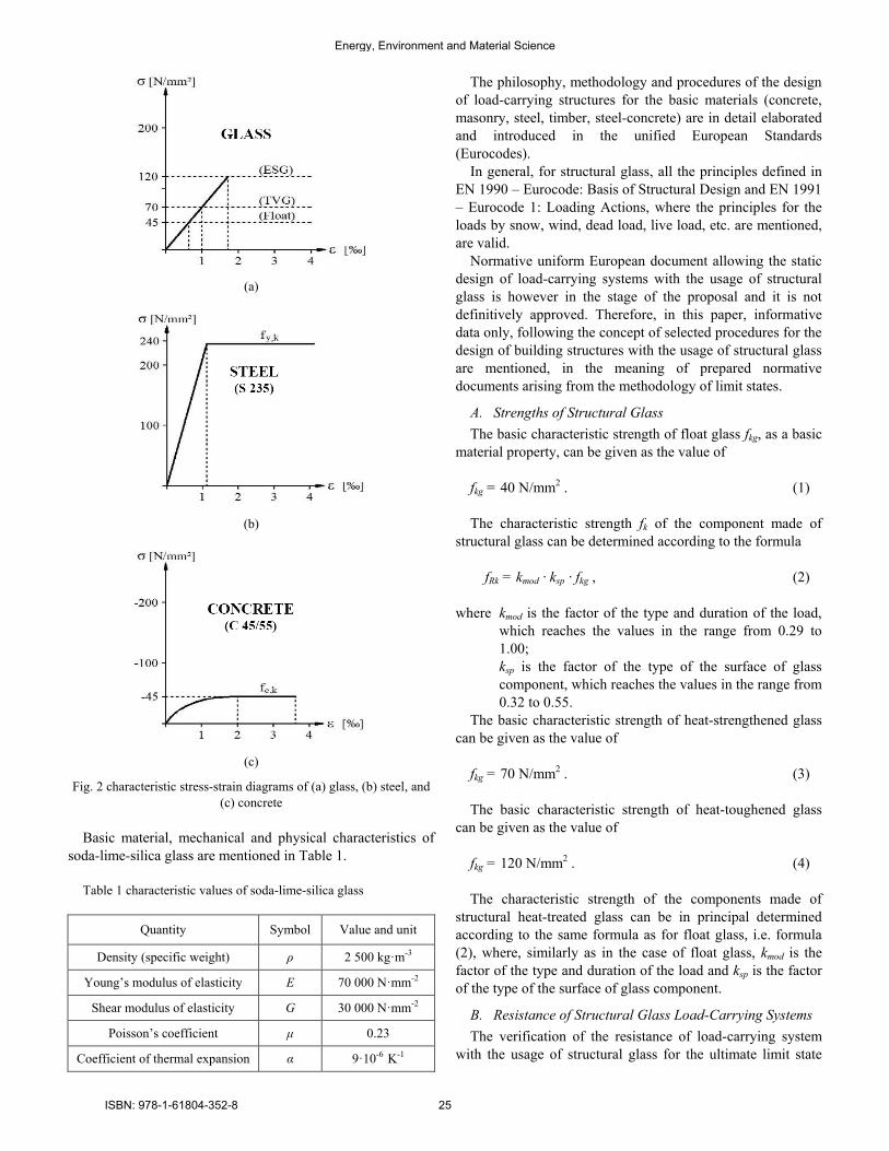
(a)
(b)
(c)
Fig 2 characteristic stress-strain diagrams of (a) glass (b) steel and
(c) concrete
Basic material mechanical and physical characteristics of
soda-lime-silica glass are mentioned in Table 1
Table 1 characteristic values of soda-lime-silica glass
Quantity Symbol Value and unit
Density (specific weight) ρ 2 500 kgmiddotm-3
Youngrsquos modulus of elasticity E 70 000 Nmiddotmm-2
Shear modulus of elasticity G 30 000 Nmiddotmm-2
Poissonrsquos coefficient μ 023
Coefficient of thermal expansion α 9middot10-6 K-1
The philosophy methodology and procedures of the design
of load-carrying structures for the basic materials (concrete
masonry steel timber steel-concrete) are in detail elaborated
and introduced in the unified European Standards
(Eurocodes)
In general for structural glass all the principles defined in
EN 1990 ndash Eurocode Basis of Structural Design and EN 1991
ndash Eurocode 1 Loading Actions where the principles for the
loads by snow wind dead load live load etc are mentioned
are valid
Normative uniform European document allowing the static
design of load-carrying systems with the usage of structural
glass is however in the stage of the proposal and it is not
definitively approved Therefore in this paper informative
data only following the concept of selected procedures for the
design of building structures with the usage of structural glass
are mentioned in the meaning of prepared normative
documents arising from the methodology of limit states
A Strengths of Structural Glass
The basic characteristic strength of float glass fkg as a basic
material property can be given as the value of
fkg = 40 Nmm2 (1)
The characteristic strength fk of the component made of
structural glass can be determined according to the formula
fRk = kmod middot ksp middot fkg (2)
where kmod is the factor of the type and duration of the load
which reaches the values in the range from 029 to
100
ksp is the factor of the type of the surface of glass
component which reaches the values in the range from
032 to 055
The basic characteristic strength of heat-strengthened glass
can be given as the value of
fkg = 70 Nmm2 (3)
The basic characteristic strength of heat-toughened glass
can be given as the value of
fkg = 120 Nmm2 (4)
The characteristic strength of the components made of
structural heat-treated glass can be in principal determined
according to the same formula as for float glass ie formula
(2) where similarly as in the case of float glass kmod is the
factor of the type and duration of the load and ksp is the factor
of the type of the surface of glass component
B Resistance of Structural Glass Load-Carrying Systems
The verification of the resistance of load-carrying system
with the usage of structural glass for the ultimate limit state
Energy Environment and Material Science
ISBN 978-1-61804-352-8 25
can be performed according to the design reliability condition
Ed le Rd (5)
where Ed is the design value of the load effect
Rd is the design value of the resistance of the structural
component or system
The design strength fRd of the structural glass component can
be determined according to the formula
fRd = fRk γM (6)
where the value of the reliability safety factor γM is
recommended to take as
γM = 12 (7)
From the viewpoint of the serviceability limit state the
permissible values of the deflections δlim are given as (up to)
δlim = L 100 (8)
where L is the span of the component between supported
edges
All the indicated design factors material characteristics and
reliability coefficients will be more in detail defined after the
approval of the prepared European document EN 13474 Glass
in Civil Engineering
In conclusion of this paragraph it should be noted that it is
not recommended to use and design the thickness of one layer
of load-carrying structural glass less than 3 mm and greater
than 25 mm
IV SELECTED EXAMPLES OF REALIZATIONS AND STUDIES
The development of the use of the building load-carrying
systems with the application of structural glass is further
indicated by the selection of illustrative examples of buildings
and project studies realized over the world but also in the
Czech Republic
Fig 3 stairs in Audio-Video Shopping Center New York
The glass stair suitably integrated to the interior of the
Audio-Video Centre in San Francisco is shown in Fig 3
(photo J Melcher) Glass does not prevent the vista to the
internal space of the building The stair grades as well as the
vertical supporting structure stiffened by supporting
transverse ribs are designed and made of glass Transverse
stiffening ribs are necessary with respect to the insurance of
the resistance of the high slender wall subjected to the vertical
compression load
Fig 4 Juilliard School in Lincoln Center New York
The structures in the areas of Lincoln Centre in New York
stiffened by twisted rope are illustrated in Fig 4 Partition
peripheral or external walls or eventually railing fillings
without significant effects of the basic loadings (vertical load
wind and so on) shall be assessed according to the technical
document ČSN EN 12600 Glass in Civil Engineering ndash
Shuttle Test ndash Method of Impact Test (ČNI Prague 2003) and
ČSN 74 3305 Protective railings (ČNI Prague 2008)
High glazed peripheral building walls ndash with respect to the
significant effects of the wind load (compression or sucking) ndash
shall be necessarily stiffened by the steel load-carrying
structure which create the support system of peripheral glass
cladding
(a) (b)
Fig 5 (a) wall in Waterloo Station London (b) hall of International
Forum Tokyo
Energy Environment and Material Science
ISBN 978-1-61804-352-8 26
In Fig 5 (a) (photo J Melcher) the structure of the glazed
wall in the area of Waterloo Station in London with the steel
support structure which is created by the truss system with
ties and struts placed both outside and inside the building is
shown In Fig 5 (b) (photo J Melcher) the structure of the
glazed wall of so-called Glass Hall in the areas of the
International Forum in Tokyo with steel support structure
created by the truss system with ties and struts placed inside
the building is shown
From the shots mentioned the arrangement of the relevant
structural system is evident and mentioned examples indicate
large diversity of the composition and structural design of
load-carrying systems with the usage of structural glass
The illustration of the successful usage of structural glass in
the Czech Republic is the oblique faccedilade of the store Sykora
Home Prague [6] in Fig 6 The wall of the faccedilade is along the
top line inclined from the vertical plane The laminated glass
panels are through the targets anchored to the steel load-
carrying structure created by lattice crosspieces which are
supported by steel columns inclined in parallel with the
faccedilade The lattice tube crosspieces are supported by the
system of rectifiable parallel ties DETAN
Fig 6 structure of oblique faccedilade of Sykora Home building Prague
The example of the usage of structural glass for the roofing
of the platform of bus station near the railway station Ostrava
ndash Svinov is shown in Fig 7 The work has been ensured by
the company METALPROGRES Inc Tetčice and on the base
of this the experimental programme [7] [9] of the verification
of load-carrying capacity and deformations of the panels made
of structural glass corresponding the real composition and
supporting of test specimens has been realized Relevant
loading tests are more in detail mentioned below in the
chapter 5
The roofing component made of two-layer tempered glass
with intermediate foil showed the possibility of the fall of
glass slab to the covered space in the case of the failure
around metal targets With regards to otherwise favourable
deformation and strength characteristics of proposed
composition of roofing panel it can be effective to eliminate
this problem by supplementary technical modification which
will exclude the fall of the failed specimens The proposed
modification lies in the inserting protective rope (see Fig 7)
under glass slab The rope is anchored to the shackles in the
axis of the bolts of circle connecting plates and it is lead
diagonally and further along the line connecting four support
nodes of glass slab The utilized steel rope had the diameter of
5 mm in general it is enough to design the rope according to
the corresponding self weight and the number of the hangings
The failed pane composed of laminated tempered glass is
detained by the protective rope it remains undivided thanks to
the stiffening effect of the foil and in addition it is capable of
transport and manipulation when replacing
Fig 7 roofing of platform of bus station Ostrava - Svinov
In the period of the last years the usage of the large-scale
glazed faccedilades of buildings has been significantly spread
Their necessary stiffening in relation to the adverse effects of
compression and sucking of the wind is ensured by the
transverse glass ribs so-called fins which are inserted in
parallel in the certain distances into the faccedilade system
Various possibilities of the composition of the glass walls
of the mentioned type are documented by the examples of the
realizations over the world but also in the Czech Republic
(a) (b)
Fig 8 (a) South Bank University London (b) Holiday Inn Paris
Energy Environment and Material Science
ISBN 978-1-61804-352-8 27
Fig 8 (a) shows the shot of the structural glass wall
stiffened by transverse glass ribs in the building of London
South Bank University Another example of the similar
solution of the restaurant glass wall in Holiday Inn Hotel in
Paris is shown in Fig 8 (b) (photo J Melcher) Further the
solution realized in Burj Al Arab Hotel in Dubai is illustrated
in Fig 9 and finally the glass wall in the building of Harbour
Grand Kowloon Hotel in Hong Kong is in Fig 10 (photo J
Melcher)
Fig 9 Burj Al Arab Hotel Dubai
Fig 10 Harbour Grand Kowloon Hotel Hong Kong
From the structures of the similar type realized in the Czech
Republic it is documented the glass faccedilade stiffened by
transverse ribs which lines the stairs tower of the new
building of the Faculty of Civil Engineering of Technical
University of Ostrava as indicated in Fig 11 (photo J
Melcher) This work was tasked by the company TOLZA
Ltd Brno The tests of the connection of the transverse rib to
the faccedilade of the type of ldquometal plate ndash glassrdquo with the usage
of two-component silicon sealant have been performed as
illustrated in Fig 12
The specimens with surface treated by powder-coated Al-
profile with coating represented by polyester thermoset
powder of PE GREY RAL7015 GLOSS or eventually
powder coating of Interpol D1036 Lesk 85 showed the
satisfactory adhesion of sealant to metal and glass and the
failure always occurred on the shear area going through
silicon part of the specimen ndash for more see eg [8]
Fig 11 structural glass faccedilade stiffened by transverse ribs ndash Faculty
of Civil Engineering Technical University of Ostrava
Fig 12 tests of sealant for glass faccedilade for Faculty of Civil
Engineering Technical University of Ostrava
The special structural group with the usage of exposed
load-carrying glass components are large aquariums in the
areas of ZOOs or social centres
Fig 13 aquarium on area of exposition of ZOO Park
Energy Environment and Material Science
ISBN 978-1-61804-352-8 28
The example of the aquarium in the interior of the building
of ZOO Park is shown in Fig 13 Probably due to the
imperfect structural solution of the spot support of the load-
carrying structure near the edge of the glass wall the
aquarium has been failed when filling by water as evident
from Fig 14 (photo J Melcher) The vertical wall of the
aquarium composed of laminated glass with the thickness of
3 x 8 = 24 mm with inserted intermediate PVB foil had the
width of 4 800 mm and the height of 2 800 mm It was
divided by vertical gaps at the thirds of the length filled by
silicon sealant The illustrative utilization of ANSYS software
(J Kala) for the elaboration of the expertise of the crash is
briefly shown in Fig 15
Fig 14 damage of aquarium after filling by water
Fig 15 illustrative utilization of ANSYS software for elaboration of
static assessment
In this connection it is also interesting to mention the
transparent wall of the greatest world aquarium in the
shopping centre Dubai Mall in Dubai illustrated in Fig 16
The transparent front wall has the width of 3288 m the
height of 83 m and the thickness of 750 mm The weight of
the wall is 245 614 kg Technically it is not the material
corresponding building glass although it is sometimes marked
as acrylic glass Chemically it is the transparent thermoplastic
PMMA (polymethylmethacrylate) often used as an alternative
to glass characterized by the small weight and the high
resistance to the fragmentation failure Its widening in the
practice has been introduced after 1933 year under the
trademark Plexiglass later ACRYLITEreg Lucite and Perspex
Fig 16 aquarium in shopping centre Dubai Mall
V VERIFICATION EXPERIMENTS AND STRUCTURAL GLASS
COMPONENTS TESTING
The authorsrsquo workplace ie the Department of Metal and
Timber Structures of the Faculty of Civil Engineering at Brno
University of Technology (BUT) pays long term attention to
the verification of the resistance and analysis of the actual
behaviour of load-carrying structural components and systems
composed of steel timber steel-concrete glass-fibre-concrete
glass combined structures and also composites eventually
other materials with considering the influence of their
imperfections (geometrical structural and constructional) ndash
see eg [9] [7] and [10] to [20]
This tradition which is continuously following has been
already introduced under the action of Professor Ferdinand
Lederer on the authorsrsquo workplace together with the accent to
the questions of the theory calculation methods and static and
structural design of the load-carrying components and systems
made of these materials
Fig 17 traditional method of uniform loading of planar components
Within the loading of the structural glass load-carrying
components the primary problem is the realization of the full
uniform load simulating compression or sucking of the wind
eventually snow load The loading process should allow
Energy Environment and Material Science
ISBN 978-1-61804-352-8 29
monitoring and recording the deflections and also damage of
tested specimens in the progress of increasing or decreasing
the load
It is evident that the traditional method of the loading of
the planar structural components by full uniform load using
weighed ballast gradually loaded at the tested specimen used
sometimes even at the front foreign research or university
workplaces (see Fig 17) is imperfect and unsuitable method
for the verification of the actual behaviour of the glass panes
In the testing room of the Department of Metal and Timber
Structures of the Faculty of Civil Engineering at BUT the
new efficient so-called vacuum test method allowing the
uniform loading of the planar structural components has been
developed after 1980 year Fig 18 shows one of the first
experiments of the type mentioned used for the verification
test of the resistance of glass fill of the railing of the bridge of
Vysočina at Velkeacute Meziřiacutečiacute (given by the task of A Pechal)
to the uniform load corresponding the effects of compression
or sucking of the wind
Fig 18 loading test of railing fill ndash bridge of Vysočina
Fig 19 scheme of arrangement of vacuum loading test of structural
glass planar component
The basic scheme of the arrangement of the vacuuming in
the loading test of the structural glass component is shown in
Fig 19 The component tested (a) is supported as corresponds
with the real structure for example line supports or single
support nodes or targets (c) anchored to the helping frames
similarly as in the real load-carrying system The slab
specimen supported as mentioned is installed to the separate
testing box (d) represented by the rigid peripheral timber
frame and the tested specimen together with the box are
covered by the transparent plastic foil (c) glued to the
stiffened floor of the testing room The floor must be
stiffened with regards to the significant effect of sucking in
the closed testing box
From the space closed under the transparent foil the air is
sucked and then the tested specimen is ideally uniformly
loaded by the effect of the atmospheric overpressure The
overpressure is measured by the electrical sensor with the
digital pressure gauge and in parallel for checking it is
verified using the liquid barometer The regime of the uniform
loading and reloading may be simply regulated and the load
intensity is determined measuring the overpressure between
the external environment and the space closed by foil The
illustrative shot of the real test of vacuum loading of structural
glass is in Fig 20
Fig 20 illustration of arrangement of real test of structural glass
Fig 21 failure of single-layer float glass ndash test specimen T1
Fig 22 failure of single-layer float glass ndash test specimen T1
Energy Environment and Material Science
ISBN 978-1-61804-352-8 30
Experiments verifying the actual behaviour of the glass
components allow analysing the deformations (deflections)
and the ultimate load-carrying capacity as well as the failure
mechanism in dependence on various material and structural
composition of the glass component
Fig 23 failure of laminated float glass ndash test specimens T3 T4
Fig 24 typical failure around local target support ndash specimens T3 T4
Fig 25 failure of laminated tempered glass ndash test specimens T5 T6
Fig 26 influence of safety rope on failure of specimens T5 T6
Characteristic examples of the failure of the glass
specimens tested within the research programme [7] [9] are
for the illustration indicated in figures below Failure of the
test specimen made of single-layer tempered glass (T1) is
characterized by breaking up to small fragments ndash see Fig 21
The test specimen made of laminated double-layer
tempered glass (T2) has been failed by tearing from the
supporting targets and by the subsequent falling of the whole
specimen ndash see Fig 22 The essentially different failure
mechanisms of the test specimens made of laminated float
glass (T3 T4) and laminated tempered glass with intermediate
foil (T5 T6) are evident from the shots in Figs 23 and 24 in
comparison with Figs 25 and 26
On the base of tests realized on the authorsrsquo workplace the
failure mechanism of the component made of structural glass
of different composition arrangement is indicated further It is
the wall component made of insulating triple-layer glass in the
arrangement according to Fig 27 (a) The tests have been
realized for the company GLASS EXPERTS Ltd Žlutice
(a)
(b)
Fig 27 loading test of pane made of insulating triple-layer glass (a)
composition of glass component (b) failure of glass component
On the base of the tests realized on the authorsrsquo workplace
the failure mechanism of the component made of structural
glass of different composition arrangement is indicated
further It is the wall component made of insulating triple-
layer glass in the arrangement according to Fig 27 (a) The
tests have been realized for the company GLASS EXPERTS
Ltd Žlutice
The test specimen is the wall component made of structural
float glass created by 3 parallel elements with the thickness of
3 x 6 mm the width of 700 mm and the length of 2 470 mm
which are connected by structural silicon on the longitudinal
sides The glass part of the test specimen is on the perimeter
mounted in the steel frame the basic part of which is
represented by the square hollow thin-walled cross-section
with the dimensions of 60 x 60 x 4 mm
Energy Environment and Material Science
ISBN 978-1-61804-352-8 31
The failure occurs suddenly at the initiation of the fracture
of glass due to the deformation in the area of the anchorage of
glass panes into the rigid peripheral steel frame The character
of the failure corresponds to the unfavourable arrangement of
used float glass as illustrated in Fig 27 (b)
VI EXPERIMENTAL VERIFICATION OF STIFFNESS
PARAMETERS OF STRUCTURAL GLASS
Within the loading tests of the structural glass panes
intended for the roofing bus station platform (see above) the
verification of stiffness parameters of glass has also been
performed to verify the actual values of Youngrsquos modulus of
elasticity and in the case of laminated double-layer glass the
actual values of the flexural stiffness and from these arising
the actual values of the second moments of area influenced by
the non-stiff connection between glass layers given by the
intermediate foil
According to the producer of glass plated structural
components mentioned above the value of Youngrsquos modulus
of elasticity of glass has been recommended as E = 70 GPa
but this is only generally considered value which has not been
verified by the producer Therefore before the loading tests
the experimental verification of the Youngrsquos modulus has
been performed at first In this connection as the second one
it was to verify the flexural stiffness of the test specimens with
regards to their composition (laminated glass with the
intermediate foil) and the production technology of glass
TEST T6 - M
000
010
020
030
040
050
0 5 10 15 20 25
wE [mm]
pE [
kP
a]
T6 - Mbod A
TEST T4 - M
000
010
020
030
040
050
0 5 10 15 20 25
wE [mm]
pE [
kP
a]
T4 - M bod A
TEST T2 - M
000
010
020
030
040
050
0 5 10 15 20 25
wE [mm]
pE [
kP
a]
T2 - M bod A
Fig 28 relationships ldquopE ndash wErdquo obtained directly from tests
TESTY T - M
0
01
02
03
04
05
0 5 10 15 20 25
wE [mm]
pE [
kP
a]
T2 - M T4 - M T6 - M
Fig 29 relationships for stiffness derivation
For this reason the test specimens have been supported on
the shorter opposite sides of the plate as the simply supported
structural members The theoretical span of the member was 2
294 mm The specimens have been subjected to the uniform
loading up to the load value about of 10 of the predicted
load-carrying capacity The specimens have been repeatedly
loaded and unloaded and the relationships of ldquoload ndash
deflectionrdquo ( ldquopE ndash wErdquo) have been monitored The ldquopE ndash wErdquo
relationships obtained from the tests for all test specimens are
illustrated in Fig 28 Using the regression analysis the linear
relationships have been derived (see Fig 29) From them
Youngrsquos modulus of elasticity the flexural stiffness and the
effective second moment of area can be determined (Table 2)
Table 2 stiffness parameters (per width of 1 m)
Specimen T1 T2 T5 T6 T3 T4
E Ieff [Nmm-2] 8654109 18029109 29568109
I = 112 bt3 [mm4] x) 144103 341103 667103
k (Ieff = k I) 10 0879 0879
E [GPa] 601 601 505
x) t is total thickness of layered glass (12 mm 2x8 mm 2x10 mm)
Using the relationship between the load pE and
corresponding deflection wE in the mid-span the effective
flexural stiffness EIeff1 can be derived if E is the modulus of
elasticity and Ieff1 is the effective second moment of area For
single-layer tempered glass (test specimens T1 T2) the
effective second moment of area is in the form of
Ieff1 = I = 112 (bmiddott3) thus k = Ieff I = 1 and from where the
modulus of elasticity E of tempered glass can be derived
directly Using this value of the elasticity modulus for
tempered layered glass (tempered glass of the same
mechanical properties) with intermediate foil (test specimens
T5 T6) and using the stiffness EIeff the effective second
moment of area of double-layer glass can be derived as
Ieff = k I where the coefficient k expresses the reduction of the
second moment of area I considered for the solid cross-section
with the thickness of t due to the influence of the pliability of
the foil connection Assuming that also for laminated non-
tempered glass (test specimens T3 T4) the influence of the
foil on the effective second moment of area may be expressed
by the same coefficient of the pliability k then the (at least
tentative) value of the elasticity modulus of non-tempered
glass can be derived
VII CONCLUSIONS
Structural glass is already the important part of the wide
spectrum of the materials of load-carrying structures of civil
engineering buildings over the world and also in the Czech
Republic Nevertheless the typical examples mentioned above
cannot systematically illustrate all the possibilities of the
structural composition and structural detailing from the
Energy Environment and Material Science
ISBN 978-1-61804-352-8 32
viewpoint of the usage of glass in civil engineering structures
but they can indicate the modern trends of the architectonic
creation of the buildings requiring the large glazed areas of
civil engineering structures and also the possibilities of their
realization in the connection with the development of the
production technology of the large scale glass components and
with the new challenges for the industry of the glass
production as well as for the structural engineers
The paper was focused on the significant field of the design
and realization of buildings with the application of structural
glass including the verification of the dimensions of the glass
components in relation to the material load intensity and
boundary conditions on the one hand and the verification of
the theoretical assumptions and design methods through the
experiments and loading tests taking into account the
influence of the initial imperfections of the real load-carrying
system on the other hand
The general philosophy and methodology of the static and
structural design of buildings using structural glass arises from
the similar general principles as in the case of other materials
of load-carrying structures However glass has many
fundamentally different properties that can influence its
behaviour in the structure (thermal shock failures of glass
caused by the material inhomogeneity due to the inclusions
spontaneous explosion material brittleness without elasto-
plastic or plastic behaviour and without the possibility to
decrease the influence of the concentrations of local stresses
necessity of the utilization of geometrically non-linear 2nd
order theory of thin slabs etc) This paper thus also tried at
least briefly to warn to some problems mentioned above
requiring more detailed consideration and cognition
ACKNOWLEDGEMENT
The paper has been elaborated within the research project
No LO1408 ldquoAdMaS UP ndash Advanced Materials Structures
and Technologiesrdquo supported by the Ministry of Education
Youth and Sport of the Czech Republic within the framework
of the National Sustainability Programme I
REFERENCES
[1] Š Popovič Production and processing of flat glass (Vyacuteroba a
zpracovaacuteniacute plocheacuteho skla ndash original in Czech language) Grada
Publishing as Praha 2009 ISBN 978-80-247-3154-4
[2] M Haldmann A Luible M Overend Structural Use of Glass Zurich
ETH Zurich 2008 215 pp ISBN 3-85748-119-2
[3] A Goris Bautabelen fur ingenieure mit Berechnungshinweisen und
Beispielen Koumlln Wolters Kluwer Deutchland GmbH 2008 555 pp
ISBN 978-3-8041-5236-6
[4] M Saacutezovskyacute ldquoHow to avoid the most common failures of structural
glass ndash I Partrdquo (ldquoJak předchaacutezet nejčastějšiacutem poruchaacutem stavebniacuteho skla
ndash I diacutelrdquo ndash original in Czech language) Stavebnictviacute Vol10 2010 pp
45-48 ISSN 1802-2030
[5] M Saacutezovskyacute ldquoHow to avoid the most common failures of structural
glass ndash II Partrdquo rdquo (ldquoJak předchaacutezet nejčastějšiacutem poruchaacutem stavebniacuteho
skla ndash II diacutelrdquo ndash original in Czech language) Stavebnictviacute Vol01 2011
pp 52-55 ISSN 1802-2030
[6] F Stejskal ldquoSteel structure of store building of Sykora Home Praha ndash
Vysočanyrdquo (ldquoOcelovaacute konstrukce stavby obchodniacuteho domu Sykora
Home v Praze Vysočanechrdquo ndash original in Czech Language) Stavebnictviacute
Vol 03 2010 p 9 ISSN 1802-2030
[7] J Melcher and M Karmaziacutenovaacute ldquoThe experimental verification of
actual behaviour of the glass roofing structure under uniform loading In
Proceedings of the 4th European Conference on Steel and Composite
Structures ldquoEUROSTEEL 2005rdquo Druck and Verlagshaus Mainz Gmbh
Aachen Maastricht 2005 Vol B pp 24-1 ndash 24-8 ISBN 3-86130-
812-6
[8] J Melcher and M Karmaziacutenovaacute ldquoStrength and deformational
characteristics of structural sealant in load-carrying connections of
structural glass componentsrdquo (ldquoPevnostniacute a přetvaacuterneacute charakteristiky
strukturaacutelniacuteho tmelu v nosnyacutech spojiacutech diacutelců z konstrukčniacuteho sklardquo ndash
original in Czech language) In Proceedings of the International
Conference ldquo70 years of Civil Engineering Faculty of Technical
University in Bratislavardquo STU Bratislava 2008 6 pp ISBN 978-80-
227-2979-6
[9] J Melcher and M Karmaziacutenovaacute ldquoThe design and experimental
verification of actual behaviour of the structural glass in roofing and
facade systemsrdquo In Proceedings of the 3rd International Conference on
Structural Engineering Mechanics and Computation ldquoSEMC 2010rdquo
held in Cape Town Millpress Rotterdam 2007 pp 657-658 ISBN
978-90-5966-054-0
[10] J Melcher ldquoBehaviour of Thin-Walled Corrugated Sheets and
Restrained Beamsrdquo In Proceedings of the IABSE Colloquium Stockholm
1986 Thin-Walled Metal Structures in Buildings IABSE ETH ndash
Houmlnggerberg Zuumlrich 1986 pp 199-206
[11] J Melcher ldquoFull-Scale Testing of Steel and Timber Structuresrdquo In
Proceedings of International Seminar Structural Assessment ndash The
role of large and full-scale testing (K S Virdi and others Ed) EampFN
SPON London 1997 pp 301ndash308 ISBN 0 419 22490 4
[12] J Melcher and M Karmaziacutenovaacute ldquoGlass and metal ndash modern materials of
civil engineering buildingsrdquo (ldquoSklo a kov ndash soudobeacute materiaacutely
občanskyacutech stavebrdquo ndash original in Czech language) In Proceedings of
the National Conference Steel Structures Hustopeče 2001 Czech
Society for Steel Structures
[13] J Melcher and M Karmaziacutenovaacute ldquoOn problems of the design of load-
carrying systems made of structural glassrdquo (ldquoK probleacutemům dimenzovaacuteniacute
nosnyacutech systeacutemů z konstrukčniacuteho sklardquo ndash original in Czech language) In
Proceedings of VIII Conference Ecology and New Building Materials
and Productsrdquo Telč VUSTAH Brno 2004
[14] J Melcher and M Karmaziacutenovaacute ldquoStructural glass in systems of
buildings roofingrdquo (ldquoKonstrukčniacute sklo v systeacutemech zastřešeniacute budovrdquo ndash
original in Czech language) In Proceedings of the 2nd International
Conference Buildings Roofing BUT ndash Faculty of Civil Engineering
Brno 2004 pp 13-18 ISBN 80-214-2588-1
[15] J Melcher and M Karmaziacutenovaacute ldquoOn problem of the design of structural
glassrdquo In Proceedings of the International Conference VSU 2005 Sofia
2005 Vol II pp 233-238 ISBN 954-331-003-3
[16] J Melcher and M Karmaziacutenovaacute ldquoOn problems of the design of load-
carrying structures made of structural glassrdquo (ldquoK probleacutemům
dimenzovaacuteniacute nosnyacutech konstrukciacute z konstrukčniacuteho sklardquo ndash original in
Czech language) Konstrukce Konstrukce Media sro Ostrava 2005
Vol 4 No 4 pp 21-24 ISSN 1213-8762
[17] M Karmaziacutenovaacute and J Melcher ldquoStructural glass in metal load-carrying
systems of building constructionsrdquo In Proceedings of the 2nd
International Conference on Advances in Civil Engineering and
Building Materials CEBM 2012 CRC Press Taylor amp Francis Group
Balkema Hong Kong 2012 pp 591-596 ISBN 978-0-415-64342-9
[18] O Pešek and J Melcher ldquoInfluence of shear forces on deformation of
structural glass beamrdquo In Proceedings of the 3rd European Conference
of Civil Engineering (ECCIErsquo12) held in Paris NAUN amp WSEAS Press
2012 pp 240-245 ISSN 2227-4588 ISBN 978-1-61804-137-1
[19] O Pešek J Melcher and M Pilgr ldquoNumerical analysis of hybrid steel-
glass beamrdquo In Proceedings of the 3rd European Conference of Civil
Engineering (ECCIErsquo12) held in Paris NAUN amp WSEAS Press 2012
pp 234-239 ISSN 2227-4588 ISBN 978-1-61804-137-1
[20] J Melcher and M Karmaziacutenovaacute ldquoProblems of behaviour and analysis of
glass structural members with respect to their application in
constructionrdquo In Proceedings of the Seventh International Structural
Engineering and Construction Conference ldquoISEC-7rdquo held in Honolulu
ldquoNew Developments in Structural Engineering and Constructionsrdquo
Research Publishing Services Singapore 2013 Vol I pp 111-116 doi
103850978-981-07-5354-2_St-43-111 ISBN-13 978-981-07-5355-9
ISBN-10 981-07-5355-1
Energy Environment and Material Science
ISBN 978-1-61804-352-8 33
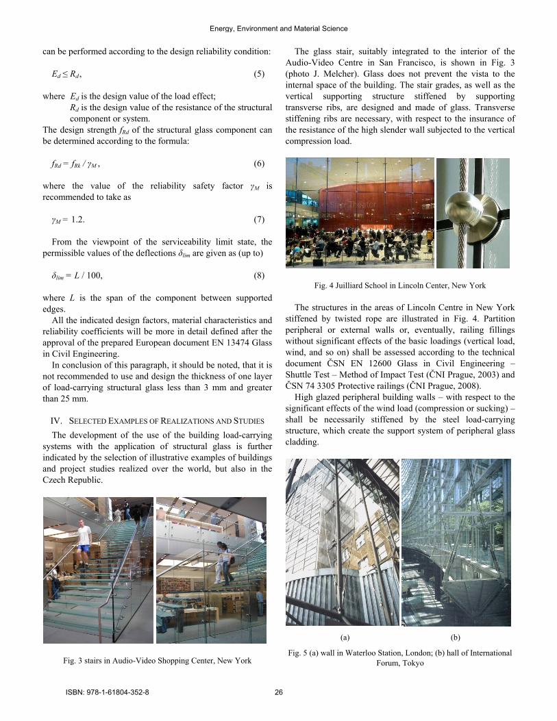
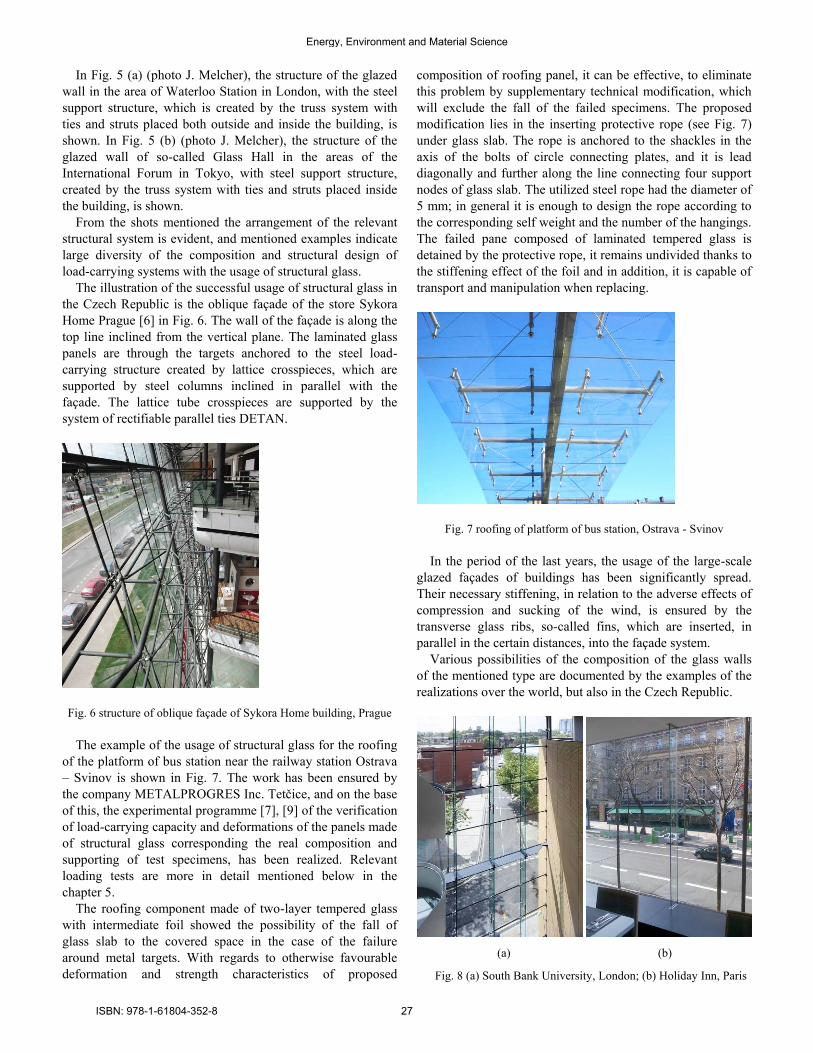
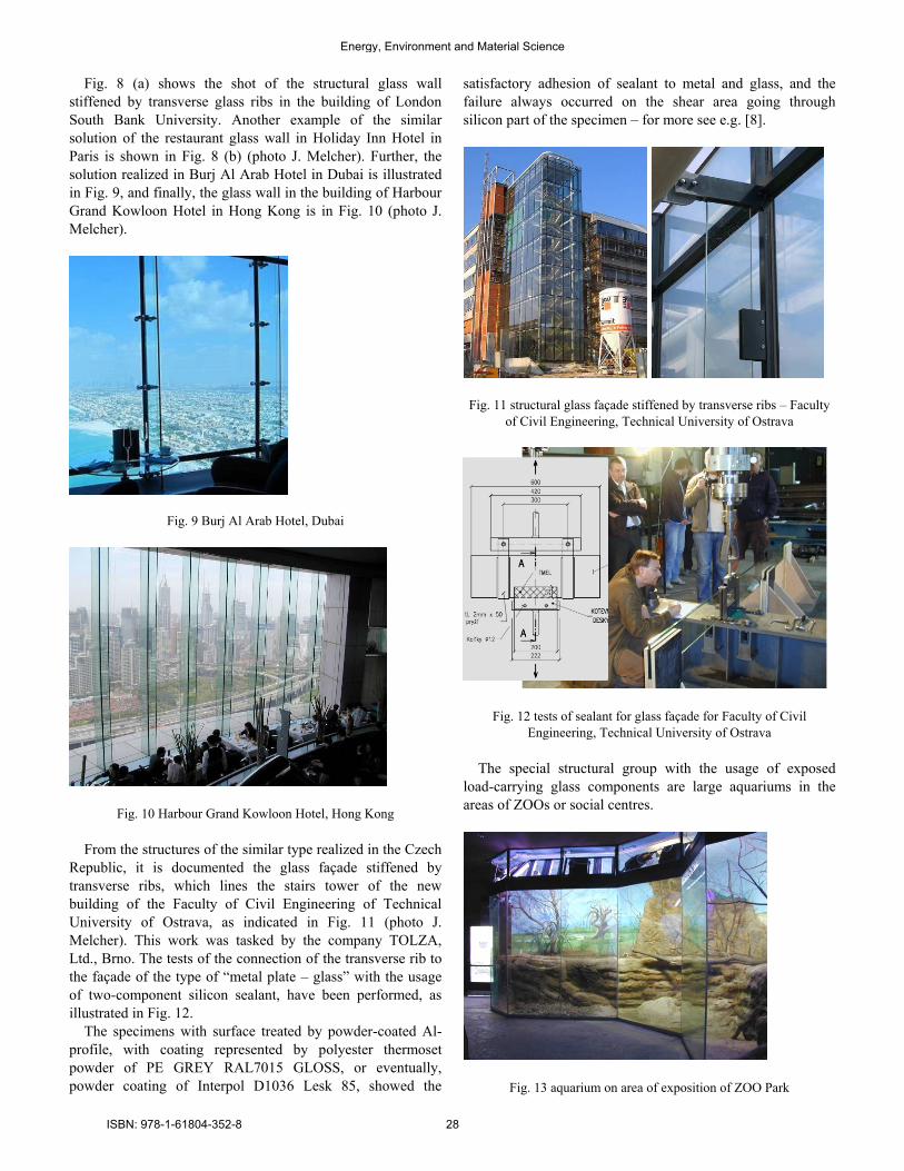
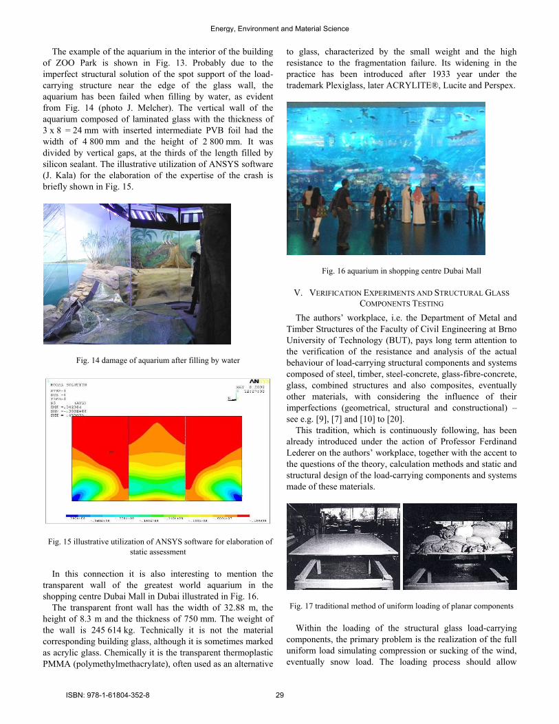
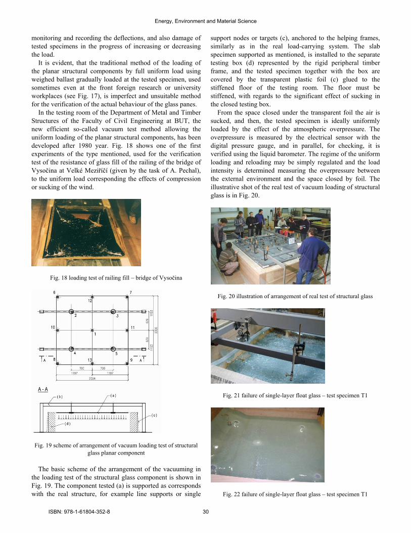
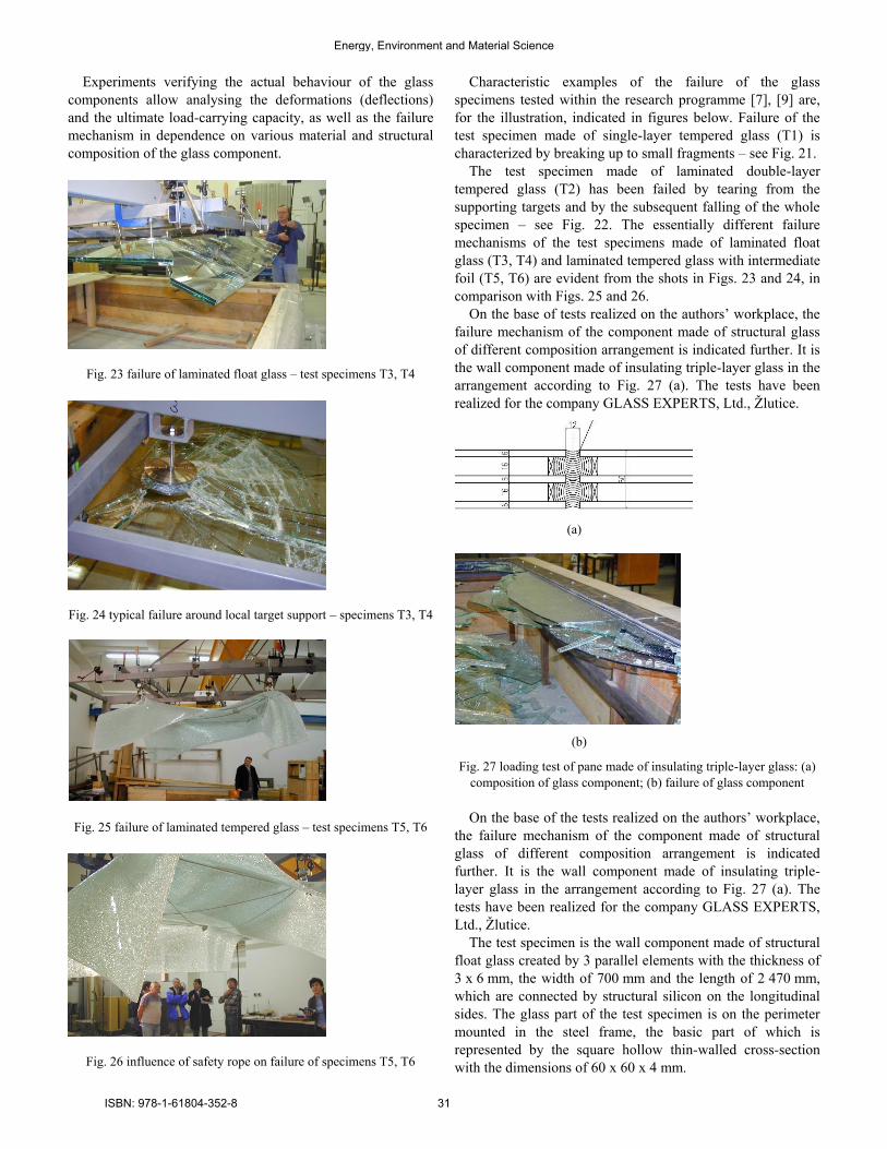
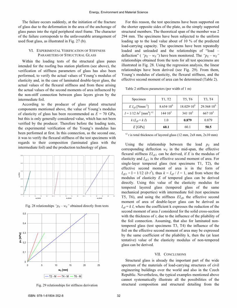