Embed Size (px)
Citation preview

GL850
USB 2.0 4-PORT HUB Controller
Datasheet Revision 1.11 Jun. 25, 2003
Genesys Logic, Inc.
GL850 USB 2.0 4-Port HUB Controller
©2000-2003 Genesys Logic Inc.—All rights reserved. Page 2
Copyright: Copyright © 2003 Genesys Logic Incorporated. All rights reserved. No part of the materials may be reproduced in any form or by any means without prior written consent of Genesys Logic Inc..
Disclaimer:
ALL MATERIALS ARE PROVIDED "AS IS" WITHOUT EXPRESS OR IMPLIED WARRANTY OF ANY KIND. NO LICENSE OR RIGHT IS GRANTED UNDER ANY PATENT OR TRADEMARK OF GENESYS LOGIC INC.. GENESYS LOGIC HEREBY DISCLAIMS ALL WARRANTIES AND CONDITIONS IN REGARD TO MATERIALS, INCLUDING ALL WARRANTIES, IMPLIED OR EXPRESS, OF MERCHANTABILITY, FITNESS FOR ANY PARTICULAR PURPOSE, AND NON-INFRINGEMENT OF INTELLECTUAL PROPERTY. IN NO EVENT SHALL GENESYS LOGIC BE LIABLE FOR ANY DAMAGES INCLUDING, WITHOUT LIMITATION, DAMAGES RESULTING FROM LOSS OF INFORMATION OR PROFITS. PLEASE BE ADVISED THAT THE MATERIALS MAY CONTAIN ERRORS OR OMMISIONS. GENESYS LOGIC MAY MAKE CHANGES TO THE MATERIALS OR TO THE PRODUCTS DESCRIBED THEREIN AT ANY TIME WITHOUT NOTICE.
Trademarks:
is a registrated trademark of Genesys Logic Inc.. All trademarks are the properties of their respective owners.
Office: Genesys Logic, Inc. 12F, No. 205, Sec. 3, Beishin Rd., Shindian City, Taipei, Taiwan Tel: (886-2) 8913-1888 Fax: (886-2) 6629-6168 http://www.genesyslogic.com

GL850 USB 2.0 4-Port HUB Controller
©2000-2003 Genesys Logic Inc.—All rights reserved. Page 3
Revision History
Revision Date Description
1.00 05/22/2003 First formal release
1.10 06/11/2003 Add Bus Power statement Gang/Individual mode setting modified
1.11 06/25/2003 Add “4 port” bus power statement

GL850 USB 2.0 4-Port HUB Controller
©2000-2003 Genesys Logic Inc.—All rights reserved. Page 4
TABLE OF CONTENTS
CHAPTER 1 GENERAL DESCRIPTION........................................................................ 9
CHAPTER 2 FEATURES................................................................................................. 10
CHAPTER 3 PIN ASSIGNMENT.................................................................................... 11
3.1 PINOUTS ....................................................................................................................... 11
3.2 PIN LIST........................................................................................................................ 12
3.3 PIN DESCRIPTIONS ....................................................................................................... 13
CHAPTER 4 BLOCK DIAGRAM................................................................................... 15
CHAPTER 5 FUNCTION DESCRIPTION .................................................................... 16
5.1 GENERAL...................................................................................................................... 16
5.1.1 USPORT Transceiver......................................................................................... 16 5.1.2 PLL (Phase Lock Loop) ..................................................................................... 16 5.1.3 FRTIMER ........................................................................................................... 16 5.1.4 µC ......................................................................................................................... 16 5.1.5 UTM (USB2.0 Transceiver Macrocell Interface) ............................................ 16 5.1.6 USPORT logic ..................................................................................................... 16 5.1.7 SIE (Serial Interface Engine)............................................................................. 16 5.1.8 Control/Status register ....................................................................................... 16 5.1.9 REPEATER ........................................................................................................ 17 5.1.10 TT (Transaction Translator) ........................................................................... 17 5.1.11 REPEATER/TT routing logic ......................................................................... 17
5.1.11.1 Connected to 1.1 Host/Hub ...................................................................... 17 5.1.11.2 Connected to USB2.0 Host/Hub .............................................................. 18
5.1.12 DSPORT logic ................................................................................................... 18 5.1.13 DSPORT Transceiver....................................................................................... 18
5.2 CONFIGURATION AND I/O SETTINGS .......................................................................... 19
5.2.1 RESET# Setting .................................................................................................. 19 5.2.2 PGANG/SUSPND Setting .................................................................................. 20 5.2.3 SELF/BUS Power Setting .................................................................................. 21 5.2.4 LED Connections ................................................................................................ 22 5.2.5 EEPROM Setting................................................................................................ 22
5.3 USB PROTOCOLS......................................................................................................... 23
GL850 USB 2.0 4-Port HUB Controller
©2000-2003 Genesys Logic Inc.—All rights reserved. Page 5
5.3.1 Host Commands and Hub Answers .................................................................. 24 5.3.1.1 Standard Requests ...................................................................................... 24 5.3.1.2 Hub Class Requests .................................................................................... 25
5.4 DESCRIPTORS ............................................................................................................... 27
5.4.1 Full Speed Case ................................................................................................... 27 5.4.1.1 Device Descriptor ........................................................................................ 27 5.4.1.2 Device Qualifier Descriptor ....................................................................... 28 5.4.1.3 Configuration Descriptor ........................................................................... 28 5.4.1.4 Interface Descriptor.................................................................................... 29 5.4.1.5 Endpoint Descriptor ................................................................................... 29 5.4.1.6 Other Speed Configuration Descriptor..................................................... 30 5.4.1.7 Interface Descriptor combined with Other Speed Configuration
Descriptor .................................................................................................... 30 5.4.1.8 Endpoint Descriptor combined with Other Speed Configuration
Descriptor .................................................................................................... 31 5.4.1.9 String Descriptor......................................................................................... 31
5.4.2 High Speed Case ................................................................................................. 32 5.4.2.1 Device Descriptor ........................................................................................ 32 5.4.2.2 Device Qualifier Descriptor ....................................................................... 33 5.4.2.3 Configuration Descriptor ........................................................................... 33 5.4.2.4 Interface Descriptor.................................................................................... 34 5.4.2.5 Endpoint Descriptor in Configuration Descriptor .................................. 34 5.4.2.6 Other Speed Configuration Descriptor..................................................... 35 5.4.2.7 Interface Descriptor in Other Speed Configuration Descriptor............. 35 5.4.2.8 Endpoint Descriptor in Other Speed Configuration Descriptor ............ 36 5.4.2.9 String Descriptor......................................................................................... 36
5.4.3 Hub Class Descriptor ......................................................................................... 37
CHAPTER 6 ELECTRICAL CHARACTERISTICS.................................................... 38
6.1 MAXIMUM RATINGS .................................................................................................... 38
6.2 DC CHARACTERISTICS................................................................................................ 38
CHAPTER 7 PACKAGE DIMENSION.......................................................................... 40

GL850 USB 2.0 4-Port HUB Controller
©2000-2003 Genesys Logic Inc.—All rights reserved. Page 6
LIST OF FIGURES
FIGURE 3.1 - PINOUT DIAGRAM ........................................................................................ 11
FIGURE 4.1 - BLOCK DIAGRAM......................................................................................... 15
FIGURE 5.1 - OPERATING IN USB1.1 SCHEME.................................................................. 17
FIGURE 5.2 - OPERATING IN USB2.0 SCHEME.................................................................. 18
FIGURE 5.3 - RESET# (EXTERNAL RESET) SETTING AND APPLICATION........................ 19
FIGURE 5.4 - POWER ON SEQUENCE OF GL850 ................................................................ 20
FIGURE 5.5 - TIMING OF PGANG/SUSPND STRAPPING................................................. 20
FIGURE 5.6 - GANG MODE SETTING ............................................................................... 21
FIGURE 5.7 - SELF/BUS POWER SETTING ...................................................................... 21
FIGURE 5.8 - LED CONNECTION ...................................................................................... 22
FIGURE 5.9 - SCHEMATICS BETWEEN GL850 AND 93C46............................................... 23
FIGURE 7.1 - GL850 64 PIN LQFP PACKAGE .................................................................. 40

GL850 USB 2.0 4-Port HUB Controller
©2000-2003 Genesys Logic Inc.—All rights reserved. Page 7
LIST OF TABLES TABLE 3.1 - PIN LIST ......................................................................................................... 12
TABLE 3.2 - PIN DESCRIPTIONS......................................................................................... 13
TABLE 5.1 - 93C46 CONFIGURATION................................................................................ 22
TABLE 5.2 - STANDARD REQUEST LIST............................................................................. 24
TABLE 5.3 - HUB CLASS REQUESTS LIST.......................................................................... 25
TABLE 5.4 - DEVICE DESCRIPTOR FOR FULL SPEED........................................................ 27
TABLE 5.5 - DEVICE QUALIFIER FOR FULL SPEED........................................................... 28
TABLE 5.6 - CONFIGURATION DESCRIPTOR FOR FULL SPEED......................................... 28
TABLE 5.7 - INTERFACE DESCRIPTOR FOR FULL SPEED.................................................. 29
TABLE 5.8 - ENDPOINT DESCRIPTOR FOR FULL SPEED.................................................... 29
TABLE 5.9 - OTHER SPEED CONFIGURATION DESCRIPTOR FOR FULL SPEED ................ 30
TABLE 5.10 - OTHER SPEED INTERFACE DESCRIPTOR FOR FULL SPEED........................ 30
TABLE 5.11 - OTHER SPEED ENDPOINT DESCRIPTOR FOR FULL SPEED ......................... 31
TABLE 5.12 - STRING INDEX0 FOR FULL SPEED............................................................... 31
TABLE 5.13 - STRING INDEX1 FOR FULL SPEED............................................................... 31
TABLE 5.14 - STRING INDEX2 FOR FULL SPEED............................................................... 32
TABLE 5.15 - DEVICE DESCRIPTOR FOR HIGH SPEED...................................................... 32
TABLE 5.16 - DEVICE QUALIFIER FOR HIGH SPEED ........................................................ 33
TABLE 5.17 - CONFIGURATION DESCRIPTOR FOR HIGH SPEED ...................................... 33
TABLE 5.18 - INTERFACE DESCRIPTOR FOR HIGH SPEED................................................ 34
TABLE 5.19 - ENDPOINT DESCRIPTOR FOR HIGH SPEED ................................................. 34
TABLE 5.20 - OTHER SPEED CONFIGURATION DESCRIPTOR FOR HIHG SPEED .............. 35
TABLE 5.21 - OTHER SPEED INTERFACE DESCRIPTOR FOR HIGH SPEED ....................... 35
TABLE 5.22 - OTHER SPEED ENDPOINT DESCRIPTOR FOR HIGH SPEED......................... 36
TABLE 5.23 - STRING INDEX0 FOR HIGH SPEED............................................................... 36
TABLE 5.24 - STRING INDEX1 FOR HIGH SPEED............................................................... 36
TABLE 5.25 - STRING INDEX2 FOR HIGH SPEED............................................................... 36
TABLE 5.26 - HUB CLASS DESCRIPTOR ............................................................................ 37

GL850 USB 2.0 4-Port HUB Controller
©2000-2003 Genesys Logic Inc.—All rights reserved. Page 8
TABLE 6.1 - MAXIMUM RATINGS ...................................................................................... 38
TABLE 6.2 - DC CHARACTERISTICS EXCEPT USB SIGNALS ........................................... 38
TABLE 6.3 - DC CHARACTERISTICS OF USB SIGNALS UNDER FS/LS MODE................. 38
TABLE 6.4 - DC CHARACTERISTICS OF USB SIGNALS UNDER HS MODE...................... 39

GL850 USB 2.0 4-Port HUB Controller
©2000-2003 Genesys Logic Inc.—All rights reserved. Page 9
CHAPTER 1 GENERAL DESCRIPTION
GL850 is a 4-port standard Universal Serial Bus (USB) hub controller complies with Universal Serial Bus Specification Revision 2.0. GL850 can be connected to an USB1.1 host/hub or an USB2.0 host/hub. When GL850 is connected to an USB1.1 host/hub, it works just like an USB1.1 hub; the upstream port will operate in full-speed (FS) and the downstream port can operate in full-speed or low-speed (LS). When GL850 is connected to an USB2.0 host/hub, it works as an USB2.0 hub; the upstream port will operate in high-speed (HS) and the downstream port can operate in high-speed, full-speed, or low-speed. The bandwidths of high speed, full speed, and low speed are 480 Mbps, 12 Mbps, and 1.5 Mbps respectively. GL850 embeds an 8-bit RISC processor to manipulate the control/status registers and responds to the requests from USB host. Firmware of GL850 will control its general purpose I/O (GPIO) to access the external EEPROM and then respond to the host the customized PID and VID configured in the external EEPROM. GL850 responds to the host the default settings in the internal ROM if there exists no external EEPROM. GL850 is designed for customers with much flexibility. Customers can easily design GL850 as 4-port self/bus powered, individual/ganged mode, by setting the I/O pins of GL850 (Ref. to Chapter 5). The more complicated settings such as PID, VID, and number of downstream ports settings are easily achieved by programming the external EEPROM. TT (transaction translator) is the main traffic control engine in an USB2.0 hub to handle the unbalanced traffic speed between the upstream port and the downstream ports. GL850 adopts single TT architecture, which shares the same TT buffer for all downstream devices. Each downstream port of GL850 supports two-color (green/amber) status LEDs to indicate normal/abnormal status. The downstream ports of GL850 can be configured as individual mode or gang mode (4 ports as a group) for power management. Gang mode is very helpful for cost consideration, since we can use one poly-fuse, but not expensive power switch chips, to detect over current. GL850 passes the current requirement (< 2.5mA) for bus-power mode when being suspended. The current consumption is smaller than 100mA for the GL850 silicon itself. The above requirements are necessary for a 4-port bus power hub. Under adequate PCB designing, GL850 provide a good choice for customers as a 4-port bus powered hub. Besides, GL850 can switch automatically between self-power mode and bus-power mode without re-plugging into the PC host. The slew rate control circuits and the power fail detection circuits inside this chip give better ESD and EMI abilities to GL850. GL850 is designed mainly for stand-alone hub. It can also be integrated into PC motherboard or any other compound devices to support USB hub function.

GL850 USB 2.0 4-Port HUB Controller
©2000-2003 Genesys Logic Inc.—All rights reserved. Page 10
CHAPTER 2 FEATURES
• Compliant to USB specification Revision 2.0 − 4 downstream ports − Upstream port supports both high-speed (HS) and full-speed (FS) traffic − Downstream ports support HS, FS, and low-speed (LS) traffic − 1 control pipe (endpoint 0, 64-byte data payload) and 1 interrupt pipe (endpoint 1, 1-byte data
payload) − Backward compatible to USB specification Revision 1.1
• On-chip 8-bit micro-processor − RISC-like architecture − USB optimized instruction set − Dual cycle instruction execution − Performance: 6 MIPS @ 12MHz − With 64-byte RAM and 2K internal ROM − Support customized PID, VID by reading external EEPROM − Support downstream port configuration by reading external EEPROM
• Single Transaction Translator (TT) architecture − Single TT shares the same TT control logics for all downstream port devices. This is the most cost
effective solution for TT
• Each downstream port supports two-color status indicator, with automatic and manual modes compliant to USB specification Revision 2.0
• Support both individual and gang modes of power management and over-current detection for downstream ports
• Conform to bus power requirements
• Automatic switching between self-powered and bus-powered modes
• Integrated USB2.0 transceiver
• 0.35um CMOS technology
• PLL embedded with external 12 MHz crystal
• Operate on 3.3 Volts
• Improved output drivers with slew-rate control for EMI reduction
• Internal power-fail detection for ESD recovery
• 64-pin LQFP package
• Applications: − Stand-alone USB hub − PC motherboard USB hub, Ducking of notebook − Any compound device to support USB HUB function

GL850 USB 2.0 4-Port HUB Controller
©2000-2003 Genesys Logic Inc.—All rights reserved. Page 11
CHAPTER 3 PIN ASSIGNMENT
3.1 Pinouts
GL850
LQFP - 64
PWREN1# 57
DGND 58
DVDD 59
GREEN1 60
AMBER1 61
AGND 62
AVDD 63
AVDD 64
AMBER2 49
PSELF 50
DGND 51
DVDD 52
PGANG/SUSPND 53
OVCUR2# 54
PWREN2# 55
OVCUR1# 56 25
24
23
22
21
20
19
18
17
32
31
30
29
28
27
26
6
DMH3
DM3
AGND
AVDD
XTAL2
XTAL1
AGND
AVDD
RREF
DPH4
DMH4
DM4
AGND
AVDD
DP3
DPH3
RPU
7
DM
1
8
DM
H1
9
DPH
1
10
DP1
11
AV
DD
12
AG
ND
13
DM
2
14
DM
H2
15
DPH
2
16
DP2
5
DPF
0
4
DPH
0
3
DM
H0
2
DM
F0
1
AG
ND
43
PWR
EN3#
42
OV
CU
R3#
41
PWR
EN4#
40
OV
CU
R4#
39
TEST
38
RES
ET#
37
DV
DD
36
DG
ND
35
AM
BER
4
34
GR
EEN
4
33
DP4
44
GR
EEN
3
45A
MB
ER3
46D
GN
D47
DV
DD
48
GR
EEN
2
Figure 3.1 - Pinout Diagram

GL850 USB 2.0 4-Port HUB Controller
©2000-2003 Genesys Logic Inc.—All rights reserved. Page 12
3.2 Pin List
Table 3.1 - Pin List
Pin# Pin Name Type Pin# Pin Name Type Pin# Pin Name Type Pin# Pin Name Type
1 AGND P 17 RREF B 33 DP4 B 49 AMBER2 O2 DMF0 B 18 AVDD P 34 GREEN4 B 50 PSELF I
3 DMH0 B 19 AGND P 35 AMBER4 O 51 DGND P
4 DPH0 B 20 XTAL1 I 36 DGND P 52 DVDD P
5 DPF0 B 21 XTAL2 O 37 DVDD P 53 PGANG/ SUSPND B
6 RPU B 22 AVDD P 38 RESET# I 54 OVCUR2# I
7 DM1 B 23 AGND P 39 TEST I 55 PWREN2# O
8 DMH1 B 24 DM3 B 40 OVCUR4# I 56 OVCUR1# I
9 DPH1 B 25 DMH3 P 41 PWREN4# O 57 PWREN1# O
10 DP1 B 26 DPH3 P 42 OVCUR3# I 58 DGND P
11 AVDD P 27 DP3 B 43 PWREN3# O 59 DVDD P
12 AGND P 28 AVDD P 44 GREEN3 B 60 GREEN1 O
13 DM2 B 29 AGND P 45 AMBER3 O 61 AMBER1 O
14 DMH2 B 30 DM4 B 46 DGND P 62 AGND P
15 DPH2 B 31 DMH4 B 47 DVDD P 63 AVDD P
16 DP2 B 32 DPH4 B 48 GREEN2 O 64 AVDD P

GL850 USB 2.0 4-Port HUB Controller
©2000-2003 Genesys Logic Inc.—All rights reserved. Page 13
3.3 Pin Descriptions
Table 3.2 - Pin Descriptions
USB Interface
Pin# Pin Name Type Description
2,3,4,5 DMF0,DMH0, DPH0,DPF0 B USB signals for USPORT
7,8,9,10 DM1,DMH1, DPH1,DP B USB signals for DSPORT1
13,14, 15,16
DM2,DMH2, DPH2,DP2 B USB signals for DSPORT2
24,25, 26,27
DM3,DMH3, DPH3,DP3 B USB signals for DSPORT3
30,31, 32,33
DM4,DMH4, DPH4,DP4 B USB signals for DSPORT2
6 RPU B RPU connects 1.5KΩ resister to 3.3V. RPU can be set to disconnected by externally resetting RESET#
17 RREF B A 510Ω resister must be connected between RREF and analog ground (AGND).
Note: USB signals must be carefully handled in PCB routing. For detailed information, please refer to GL850 Design Guideline.
HUB Interface
Pin# Pin Name Type Description
56,54, 42,40
OVCUR1#~ OVCUR4#
I (pu)
Active low. Over current indicator for DSPORT1~ DSPORT4 For GANG mode, OVCUR1# is the only over current flag for GL850
57,55, 43,41
PWREN1#~ PWREN4#
O (pu)
Active low. Power enable output for DSPORT1~ DSPORT4 For GANG mode, PWREN1# is the only power enable output for GL850.
60,48, 44,34
GREEN1~ GREEN4
O (pd) Green LED indicator for DSPORT1~DSPORT4
61,49, 45,35
AMBER1~ AMBER4
O (pd)
Amber LED indicator for DSPORT4~DSPORT1 *AMBER[4~1] are also used to access the external EEPROM. For detailed information, please refer to Chapter 5.
50 PSELF I 0: GL850 is bus-powered. 1: GL850 is self-powered.
53 PGANG/ SUSPND
B (pd)
This pin is default put in input mode after power-on reset. Individual/gang mode is strapped during this period. After the strapping period, this pin will be set to output mode, and then output high for normal mode. When GL850 is suspended, this pin will output low. *For detailed explanation, please see Chapter 5 Input: 0: individual, 1: gang Output: 0: suspend, 1: normal

GL850 USB 2.0 4-Port HUB Controller
©2000-2003 Genesys Logic Inc.—All rights reserved. Page 14
Clock and Reset Interface
Pin# Pin Name Type Description
20 XTAL1 I 12MHz crystal clock input.
21 XTAL2 O 12MHz crystal clock output.
38 RESET# I Active low. External reset input, default pull high 100KΩ. When RESET# = low, whole chip is reset to the initial state.
System Interface
Pin# Pin Name Type Description
39 TEST I (pd)
0: Normal operation. 1: Chip will be put in test mode.
Power / Ground
Pin# Pin Name Type Description 11,18, 22,28, 63,64
AVDD P Analog power input for analog circuits.
1,12,19, 23,29,
62 AGND P Analog ground input for analog circuits.
37,47, 52,59 DVDD P Digital power input for digital circuits.
36,46, 51,58 DGND P Digital ground input for digital circuits.
Note: Analog circuits are quite sensitive to power and ground noise. PCB layout must take care the power routing and the ground plane. For detailed information, please refer to GL850 Design Guideline.
Notation: Type O Output I Input B Bi-directional B/I Bi-directional, default input B/O Bi-directional, default output P Power / Ground A Analog SO Automatic output low when suspend pu Internal pull up pd Internal pull down odpu Open drain with internal pull up

GL850 USB 2.0 4-Port HUB Controller
©2000-2003 Genesys Logic Inc.—All rights reserved. Page 15
CHAPTER 4 BLOCK DIAGRAM
FRTIMERUSPORT
Transceiver
RAM
CPU
Control/Status
RegisterUTMI
USPORT
LogicSIE
D+ D-
GPIO
REPEATER
REPEATER / TT Routing Logic
DSPORT1 Logic DSPORT2 Logic DSPORT3 Logic DSPORT4 Logic
DSPORT
Transceiver
DSPORT DSPORT DSPORT
12MHz
D+ D- LED/OVCUR/PWRENB
D+ D- LED/OVCUR/PWRENB
D+ D- LED/OVCUR/PWRENB
D+ D- LED/OVCUR/PWRENB
TT (Transaction Translator)
PLL
x40, x10
Transceiver Transceiver Transceiver
ROM
Figure 4.1 - Block Diagram

GL850 USB 2.0 4-Port HUB Controller
©2000-2003 Genesys Logic Inc.—All rights reserved. Page 16
CHAPTER 5 FUNCTION DESCRIPTION
5.1 General
5.1.1 USPORT Transceiver USPORT (upstream port) transceiver is the analog circuit that supports both full-speed and high-speed electrical characteristics defined in chapter 7 of USB specification Revision 2.0. USPORT transceiver will operate in full-speed electrical signaling when GL850 is plugged into a 1.1 host/hub. USPORT transceiver will operate in high-speed electrical signaling when GL850 is plugged into a 2.0 host/hub.
5.1.2 PLL (Phase Lock Loop) Gl850 contains a 40x PLL and a 10x PLL. PLL generates the clock sources for the whole chip. The generated clocks are proven quite accurate that help in generating high speed signal without jitter.
5.1.3 FRTIMER This module implements hub (micro)frame timer. The (micro)frame timer is derived from the hub’s local clock and is synchronized to the host (micro)frame period by the host generated Start of (micro)frame (SOF). FRTIMER keeps tracking the host’s SOF such that GL850 is always safely synchronized to the host. The functionality of FRTIMER is described in section 11.2 of USB Specification Revision 2.0.
5.1.4 μC μC is the micro-processor unit of GL850. It is an 8-bit RISC processor with 2K ROM and 64 bytes RAM. It operates at 6MIPS of 12Mhz clock to decode the USB command issued from host and then prepares the data to respond to the host. In addition, μC can handle GPIO (general purpose I/O) settings and reading content of EEPROM to support high flexibility for customers of different configurations of hub. These configurations include self/bus power mode setting, individual/gang mode setting, downstream port number setting, device removable/non-removable setting, and PID/VID setting.
5.1.5 UTM (USB2.0 Transceiver Macrocell Interface) UTMI handles the low level USB protocol and signaling. It’s designed based on the Intel’s UTMI specification 1.01. The major functions of UTMI logic are to handle the data and clock recovery, NRZI encoding/decoding, Bit stuffing /de-stuffing, supporting USB2.0 test modes, and serial/parallel conversion.
5.1.6 USPORT logic USPORT implements the upstream port logic defined in section 11.6 of USB specification Revision 2.0. It mainly manipulates traffics in the upstream direction. The main functions include the state machines of Receiver and Transmitter, interfaces between UTMI and SIE, and traffic control to/from the REPEATER and TT.
5.1.7 SIE (Serial Interface Engine) SIE handles the USB protocol defined in chapter 8 of USB specification Revision 2.0. It co-works with μC to play the role of the hub kernel. The main functions of SIE include the state machine of USB protocol flow, CRC check, PID error check, and timeout check. Unlike USB1.1, bit stuffing/de-stuffing is implemented in UTMI, not in SIE.
5.1.8 Control/Status register Control/Status register is the interface register between hardware and firmware. This register contains the information necessary to control endpoint0 and endpoint1 pipelines. Through the firmware based architecture, GL850 possesses higher flexibility to control the USB protocol easily and correctly.

GL850 USB 2.0 4-Port HUB Controller
©2000-2003 Genesys Logic Inc.—All rights reserved. Page 17
5.1.9 REPEATER Repeater logic implements the control logic defined in section 11.4 and section 11.7 of USB specification Revision 2.0. REPEATER controls the traffic flow when upstream port and downstream port are signaling in the same speed. In addition, REPEATER will generate internal resume signal whenever a wakeup event is issued under the situation that hub is globally suspended.
5.1.10 TT (Transaction Translator) TT implements the control logic defined in section 11.14 ~ 11.22 of USB specification Revision 2.0. TT basically handles the unbalanced traffic speed between the USPORT (operating in HS) and DSPORTS (operating in FS/LS) of hub. GL850 adopts the single TT architecture to provide the most cost effective solution. Single TT shares the same buffer control module for each downstream port.
5.1.11 REPEATER/TT routing logic REPEATER and TT are the major traffic control machines in the USB2.0 hub. Under situation that USPORT and DSPORT are signaling in the same speed, REPEATER/TT routing logic switches the traffic channel to the REPEATER. Under situation that USPORT is in the high speed signaling and DSPORT is in the full/low speed signaling, REPEATER/TT routing logic switches the traffic channel to the TT.
5.1.11.1 Connected to 1.1 Host/Hub If an USB2.0 hub is connected to the downstream port of an USB1.1 host/hub, it will operate in USB1.1 mode. For an USB1.1 hub, both upstream direction traffic and downstream direction traffic are passing through REPEATER. That is, the REPEATER/TT routing logic will route the traffic channel to the REPEATER.
USB1.1 HOST/HUB
REPEATER TT
DSPORT operatingin FS/LS signaling
USPORToperatingin FS signaling
Traffic channelis routed toREPEATER
Figure 5.1 - Operating in USB1.1 scheme

GL850 USB 2.0 4-Port HUB Controller
©2000-2003 Genesys Logic Inc.—All rights reserved. Page 18
5.1.11.2 Connected to USB2.0 Host/Hub If an USB2.0 hub is connected to an USB2.0 host/hub, it will operate in USB2.0 mode. The upstream port signaling is in high speed with bandwidth of 480 Mbps under this environment. The traffic channel will then be routed to the REPEATER when the device connected to the downstream port is signaling also in high speed. On the other hand, the traffic channel will then be routed to TT when the device connected to the downstream port is signaling in full/low speed.
USB2.0 HOST/HUB
REPEATER TT
USPORToperatingin HS signaling
HS vs. FS/LS:Traffic channelis routed to TT
HS vs. HS:Traffic channel isrouted to REPEATER
DSPORT operatingin HS signaling
DSPORT operatingin FS/LS signaling
Figure 5.2 - Operating in USB2.0 scheme
5.1.12 DSPORT logic DSPORT (downstream port) logic implements the control logic defined in section 11.5 of USB specification Revision 2.0. It mainly manipulates the state machine, the connection/disconnection detection, over current detection and power enable control, and the status LED control of the downstream port. Besides, it also output the control signals to the DSPORT transceiver.
5.1.13 DSPORT Transceiver DSPORT transceiver is the analog circuit that supports high-speed, full-speed, and low-speed electrical characteristics defined in chapter 7 of USB specification Revision 2.0. In addition, each DSPORT transceiver accurately controls its own squelch level to detect the detachment and attachment of devices.

GL850 USB 2.0 4-Port HUB Controller
©2000-2003 Genesys Logic Inc.—All rights reserved. Page 19
5.2 Configuration and I/O Settings
5.2.1 RESET# Setting When RESET# is low enabled, the whole chip is put in initial state. In addition, RPU will disable the pull-up 1.5KΩ resister to 3.3V, which causes GL850 seems to be disconnected to the host. We suggest configure RESET# as following figure. Vbus is the 5V input from USB cable. GL850 will always be in disconnected state when USB cable is not plugged into host, even that GL850 is powered.
RESETIVbus(5V)
AVDD(3.3V)
1.5K ohm
RPU
DPF0
Inside GL850On PCB
CR
RESET#
Figure 5.3 - RESET# (External Reset) setting and application
GL850 internally contains a power on reset circuit. The power on sequence is depicted in the next picture. To fully control the reset process of GL850, we suggest the reset time applied in the external reset circuit should more than that of the internal reset circuit.

GL850 USB 2.0 4-Port HUB Controller
©2000-2003 Genesys Logic Inc.—All rights reserved. Page 20
≒ 2.7 μs
Internal reset
External reset
Power good voltage, 2.5~2.8V
VCC(3.3V)
Figure 5.4 - Power on sequence of GL850
5.2.2 PGANG/SUSPND Setting
To save pin count, GL850 uses the same pin to decide individual/gang mode as well as to output the suspend flag. The individual/gang mode is decided in the period of 1ms after power on reset. After that period of time, this pin is changed to output mode. GL850 outputs the suspend flag once it is globally suspended. For individual mode, a pull low resister greater than 100KΩ should be placed. For gang mode, a pull high resister greater than 100KΩ should be placed. In figure 5.6, we also depict the suspend LED indicator schematics. It should be noticed that the polarity of LED must be followed, otherwise the suspend current will be over than the current limitation (2.5mA).
RESET#
GANG_CTL
1 ms
Input mode, strappingto decide individual organg mode
Output mode, indicatingGL850 is in normalmode or suspend mode
Figure 5.5 - Timing of PGANG/SUSPND strapping

GL850 USB 2.0 4-Port HUB Controller
©2000-2003 Genesys Logic Inc.—All rights reserved. Page 21
DVDD(3.3V)
100K ohm
100K ohm
DVDD(3.3V)
Suspend LEDIndicator
Suspend LEDIndicator
GAND Mode
IndividualMode
"0": Individual Mode"1": GANG Mode
SUSPNDO
GANG_CTL
Inside GL850On PCB
Figure 5.6 - GANG Mode Setting
5.2.3 SELF/BUS Power Setting GL850 can operate under bus power and conform to the power consumption limitation completely (suspend current < 2.5 mA, normal operation current < 100 mA). By setting PSELF, GL850 can be configured as a bus-power or a self-power hub.
1: Power Self
0: Power Bus
PSELF
Inside GL850
On PCB
Figure 5.7 - SELF/BUS Power Setting

GL850 USB 2.0 4-Port HUB Controller
©2000-2003 Genesys Logic Inc.—All rights reserved. Page 22
5.2.4 LED Connections GL850 controls the LED lighting according to the flow defined in section 11.5.3 of Universal Serial Bus Specification Revision2.0. Both manual mode and Automatic mode are supported in GL850. When GL850 is globally suspended, GL850 will turn off the LED to save power.
AMBER/GREEN
Inside GL850On PCB
DGND
LED
Figure 5.8 - LED Connection
5.2.5 EEPROM Setting
GL850 replies to host commands by the default settings in the internal ROM. GL850 also offers the ability to reply to the host according to the settings in the external EEPROM(93C46). The following table shows the configuration of 93C46.
Table 5.1 - 93C46 Configuration
00h 01h 02h 03h 04h 05h 06h 07h
00 VID_H VID_L PID_H PID_L CHKSUM FF PORT_NO DEVICE REMOVABLE FF FF FF FF FF FF FF FF
08 VENDOR LENGTH XX XX XX XX XX XX XX XX XX XX XX XX XX XX XX
10 XX XX XX XX XX XX XX XX XX XX XX XX XX XX XX XX18 XX XX XX XX XX XX XX XX XX XX XX XX XX XX XX XX
20 PRODUCT LENGTH XX XX XX XX XX XX XX XX XX XX XX XX XX XX XX
28 XX XX XX XX XX XX XX XX XX XX XX XX XX XX XX XX30 XX XX XX XX XX XX XX XX XX XX XX XX XX XX XX XX
38 SERIAL
NUMBER LENGTH
XX XX XX XX XX XX XX XX XX XX XX XX XX XX XX
40 XX XX XX XX XX XX XX XX XX XX XX XX XX XX XX XX48 XX XX XX XX XX XX XX XX XX XX XX XX XX XX XX XXNote: 1. VID_H/VID_L: high/low byte of VID value 2. PID_H/PID_L: high/low byte of PID value 3. CHKSUM: CHKSUM must equal to VID_H + VID_L + PID_H + PID_L + 1,otherwise
firmware will ignore the EEPROM settings.

GL850 USB 2.0 4-Port HUB Controller
©2000-2003 Genesys Logic Inc.—All rights reserved. Page 23
4. PORT_NO: port number, value must be 1~4. 5. DEVICE REMOVALBE:
- - - PORT4 REMOVABLE
PORT3 REMOVABLE
PORT2 REMOVABLE
PORT1 REMOVABLE -
0: Device attached to this port is removable. 1: Device attached to this port is non-removable.
6. VENDOR LENGTH: offset 08h contains the length of the vendor string. Values of vendor string is contained from 09h~1fh.
7. PRODUCT LENGTH: offset 20h contains the length of product string. Values of product string is contained from 21h~37h.
8. SERIAL NUMBER LENGTH: offset 38h contains the value of serial number string. Values of serial number string is contained after offset 39h.
The schematics between GL850 and 93C46 is depicted in the following figures:
VCC
NC
NC
GND
CS
SK
DI
DO
AMBER1
GREEN1
AMBER2
PGANG
93C46
DVDD
Figure 5.9 - Schematics Between GL850 and 93C46
GL850 firstly verifies the check sum after power on reset. If the check sum is correct, GL850 will take the configuration of 93C46 as part of the descriptor contents. To prevent the content of 93C46 from being over-written, amber LED will be disabled when 93C46 exists.
5.3 USB Protocols To behave as a standard USB2.0 hub, some protocols defined in Chapter 9 and Chapter 11 of Universal Serial Bus Specification Revision 2.0 must be followed. We firstly classify these standard requests and hub class requests in section 6.1. Descriptors are described in section 6.2, which contain the detailed information for the hub.

GL850 USB 2.0 4-Port HUB Controller
©2000-2003 Genesys Logic Inc.—All rights reserved. Page 24
5.3.1 Host Commands and Hub Answers An USB hub needs at least 2 endpoints to guarantee the normal operation. Endpoint 0 is the default control pipe. Endpoint 1 is the interrupt pipe. Host gets all the information about the hub and through the control pipe. Hub information like self/bus power and gang/individual mode is all replied to host via endpoint0. Interrupt pipe is to report to the host the updated change of hub status (power change and over current change, for example) and the updated status change of all downstream ports (connect change, suspend change, over current change, etc.).
5.3.1.1 Standard Requests
Table 5.2 - Standard Request List
Request bmRequestType bRequest wValue wIndex wLength Return GET_DESCRIPTOR (Device) 10000000b 06h 0100h 0000h 0012h Device Descriptor
(Note1) GET_DESCRIPTOR (Device_Qualifier) 10000000b 06h 0600h 0000h 000Ah Device_Qualifier
Descriptor (Note1)
GET_DESCRIPTOR (Configuration) 10000000b 06h 0200h 0000h 0019h
Configuration+Interface+Endpoint Descriptors (Note1)
GET_DESCRIPTOR (Other_Speed_Configuration)
10000000b 06h 0700h 0000h 0019h
Other_Speed_ Configuration+Interface+Endpoint Descriptors (Note1)
GET_DESCRIPTOR (String Index0) 10000000h 06h 0300h 0000h 0004h String Descriptor Index0
(Note1) GET_DESCRIPTOR (String Index1) 10000000h 06h 0301h 0409h 0020h String Descriptor Index1
(Note1) GET_DESCRIPTOR (String Index2) 10000000h 06h 0302h 0409h 002Ch String Descriptor Index2
(Note1)
SET_ADDRESS 00000000b 05h 0000h ~ 007Fh 0000h 0000h Zero length packet
SET_CONFIGURATION 00000000b 09h 0000h/
0001h 0000h 0000h Zero length packet
GET_CONFIGURATION 00000000b 08h 0000h
0000h 0001h Configuration value
SET_INTERFACE 00000001b 0Bh 0000h 0000h 0000h Zero length packet SET_FEATURE (Remote wakeup ability)
00000000b 03h 0001h 0000h 0000h Zero length packet
SET_FEATURE (Endpoint0 halt) no support
00000010b 03h 0000h 0000h/0080h 0000h Zero length packet
SET_FEATURE (Endpoint1 halt) 00000010b 03h 0000h 0081h 0000h Zero length packet
CLEAR_FEATURE (Remote wakeup ability)
00000000b 01h 0001h 0000h 0000h Zero length packet
CLEAR_FEATURE (Endpoint0 halt) no support
00000010b 01h 0000h 0000h/0080h 0000h Zero length packet
GL850 USB 2.0 4-Port HUB Controller
©2000-2003 Genesys Logic Inc.—All rights reserved. Page 25
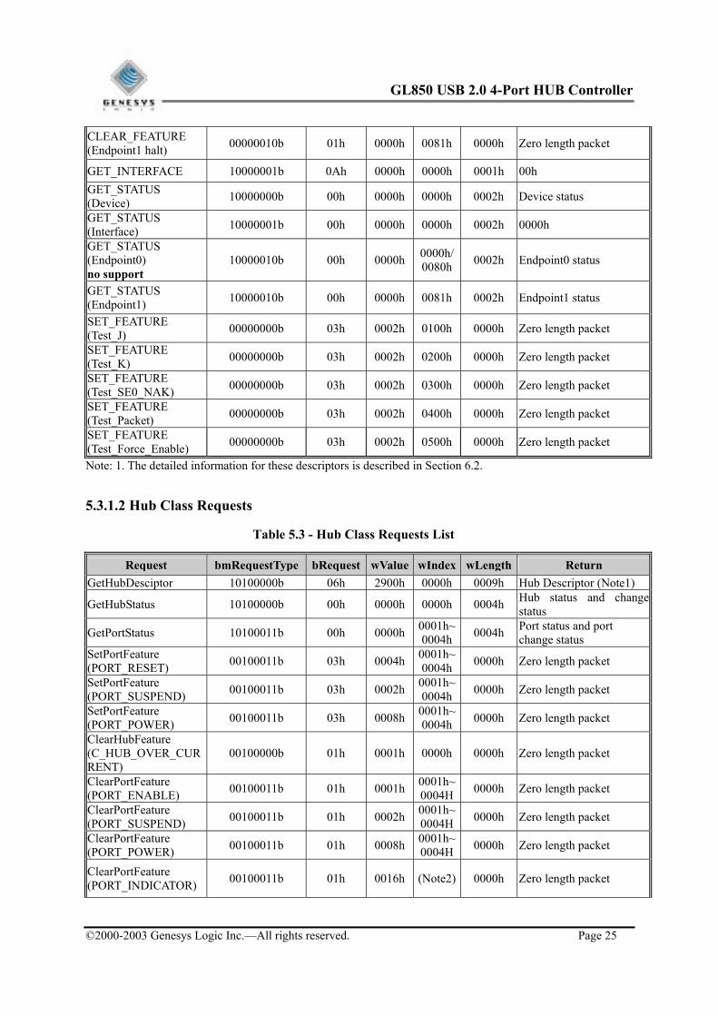
CLEAR_FEATURE (Endpoint1 halt) 00000010b 01h 0000h 0081h 0000h Zero length packet
GET_INTERFACE 10000001b 0Ah 0000h 0000h 0001h 00h GET_STATUS (Device) 10000000b 00h 0000h 0000h 0002h Device status
GET_STATUS (Interface) 10000001b 00h 0000h 0000h 0002h 0000h
GET_STATUS (Endpoint0) no support
10000010b 00h 0000h 0000h/0080h 0002h Endpoint0 status
GET_STATUS (Endpoint1) 10000010b 00h 0000h 0081h 0002h Endpoint1 status
SET_FEATURE (Test_J) 00000000b 03h 0002h 0100h 0000h Zero length packet
SET_FEATURE (Test_K) 00000000b 03h 0002h 0200h 0000h Zero length packet
SET_FEATURE (Test_SE0_NAK) 00000000b 03h 0002h 0300h 0000h Zero length packet
SET_FEATURE (Test_Packet) 00000000b 03h 0002h 0400h 0000h Zero length packet
SET_FEATURE (Test_Force_Enable) 00000000b 03h 0002h 0500h 0000h Zero length packet
Note: 1. The detailed information for these descriptors is described in Section 6.2.
5.3.1.2 Hub Class Requests
Table 5.3 - Hub Class Requests List
Request bmRequestType bRequest wValue wIndex wLength Return GetHubDesciptor 10100000b 06h 2900h 0000h 0009h Hub Descriptor (Note1)
GetHubStatus 10100000b 00h 0000h 0000h 0004h Hub status and change status
GetPortStatus 10100011b 00h 0000h 0001h~0004h 0004h Port status and port
change status SetPortFeature (PORT_RESET) 00100011b 03h 0004h 0001h~
0004h 0000h Zero length packet
SetPortFeature (PORT_SUSPEND) 00100011b 03h 0002h 0001h~
0004h 0000h Zero length packet
SetPortFeature (PORT_POWER) 00100011b 03h 0008h 0001h~
0004h 0000h Zero length packet
ClearHubFeature (C_HUB_OVER_CURRENT)
00100000b 01h 0001h 0000h 0000h Zero length packet
ClearPortFeature (PORT_ENABLE) 00100011b 01h 0001h 0001h~
0004H 0000h Zero length packet
ClearPortFeature (PORT_SUSPEND) 00100011b 01h 0002h 0001h~
0004H 0000h Zero length packet
ClearPortFeature (PORT_POWER) 00100011b 01h 0008h 0001h~
0004H 0000h Zero length packet
ClearPortFeature (PORT_INDICATOR) 00100011b 01h 0016h (Note2) 0000h Zero length packet

GL850 USB 2.0 4-Port HUB Controller
©2000-2003 Genesys Logic Inc.—All rights reserved. Page 26
ClearPortFeature (C_PORT_CONNECTION)
00100011b 01h 0010h 0001h~0004h 0000h Zero length packet
ClearPortFeature (C_PORT_RESET) 00100011b 01h 0014h 0001h~
0004h 0000h Zero length packet
ClearPortFeature (C_PORT_ENABLE) 00100011b 01h 0011h 0001h~
0004h 0000h Zero length packet
ClearPortFeature (C_PORT_SUSPEND) 00100011b 01h 0012h 0001h~
0004h 0000h Zero length packet
ClearPortFeature (C_PORT_OVER_CURRENT)
00100011b 01h 0013h 0001h~0004h 0000h Zero length packet
SetPortFeature (PORT_TEST:TEST_J) 00100011b 03h 0015h 0101h~
0104h 0000h Zero length packet
SetPortFeature (PORT_TEST:TEST_K)
00100011b 03h 0015h 0201h~0204h 0000h Zero length packet
SetPortFeature (PORT_TEST: TEST_SE0_NAK)
00100011b 03h 0015h 0301h~0304h 0000h Zero length packet
SetPortFeature (PORT_TEST: TEST_PACKET)
00100011b 03h 0015h 0401h~0404h 0000h Zero length packet
SetPortFeature (PORT_TEST: TEST_FORCE_ENABLE)
00100011b 03h 0015h 0501h~0504h 0000h Zero length packet
SetPortFeature (PORT_INDICATOR) 00100011b 03h 0016h (Note2) 0000h Zero length packet
ClearTTBuffer 00100011b 08h (Note3) 0001h 0000h Zero length packet
GetTTStatus 10100011B 0Ah 0000h 0001h 08D0h? TT state
ResetTT 00100011b 09h 0000h 0001h 0000h Zero length packet
StopTT 00100011B 0Bh 0000h 0001h 0000h Zero length packet
Note: 1. Hub descriptor is described in Section 6.2. 2. High byte of wIndex is the port indicators selector code, low byte of wIndex is the port number. For
detailed information, please refer to the section 11.24.2.13 of Universal Serial Bus Specification Revision 2.0.
3. The device address, endpoint number, and endpoint type of the full-/low-speed endpoint that may have a busy TT buffer must be specified in the wValue field. For detailed information, please refer to the table 11-18 of section 11.24.2.3 of Universal Serial Bus Specification Revision 2.0.

GL850 USB 2.0 4-Port HUB Controller
©2000-2003 Genesys Logic Inc.—All rights reserved. Page 27
5.4 Descriptors Descriptors contain all the information about the USB2.0 hub. Host asks different types of descriptors by different GET_DESCRIPTOR commands. Hub will reply to different GET_DESCRIPTOR the associated descriptors to let host know how to configure the hub. For an USB2.0 hub, the descriptors are:
Device Descriptor
Device Qualifier Descriptor
Configuration Descriptor
Interface Descriptor
Endpoint Descriptor
Other Speed Configuration Descriptor
Hub Class-specific Descriptor
String Descriptor
Descriptors replied are different between full speed and high speed for an USB2.0 hub. Once an USB2.0 hub is plugged into a host/hub, it needs to firstly decide the host/hub is an USB1.1 host/hub or an USB2.0 host/hub. If the host/hub being plugged is an USB1.1 hub, GL850 replies to the host the full speed descriptors defined in section 6.2.1. Otherwise, GL850 replies the high speed descriptors defined in section 6.2.2. For hub class-specific descriptor, there’s no difference between full speed and high speed.
5.4.1 Full Speed Case
5.4.1.1 Device Descriptor Hub returns Device Descriptor when GET_DESCRIPTOR (DEVICE) command is requested.
Table 5.4 - Device Descriptor for Full Speed
Offset Field Value Description I/O Configuration
EEPROMConfiguration
0 bLength 12h 18 bytes for this descriptor - -
1 bDescriptorType 01h Device descriptor type - -
2 bcdUSB 0200h USB2.0 compliance - -
4 bDeviceClass 09h Hub class code - -
5 bDeviceSubClass 00h Subclass code - -
6 bDeviceProtocol 00h Protocol code - -
7 bMaxPacktSize0 40h Max. packet size of endpoint0 - -
8 idVendor 05E3h Vendor ID of Genesys Logic Inc. - Y
10 idProduct 0660h Product ID of Genesys Logic Inc. - Y
12 bcdDevice xxxxh Version Control - Y 14 iManufacturer 00h Index of vendor string - Y 15 idProduct 01h Index of product string - Y 16 iSerialNumber 00h Index of serial number - Y 17 bNumConfigurations 01h Number of configuration - -

GL850 USB 2.0 4-Port HUB Controller
©2000-2003 Genesys Logic Inc.—All rights reserved. Page 28
5.4.1.2 Device Qualifier Descriptor Hub returns Device Qualifier Descriptor when GET_DESCRIPTOR (DEVICE_QUALIFIER) command is issued from host.
Table 5.5 - Device Qualifier for Full Speed
Offset Field Value Description I/O Configuration
EEPROMConfiguration
0 bLength 0Ah 10 bytes for this descriptor - -
1 bDescriptorType 06h Device qualifier descriptor type - -
2 bcdUSB 0200h USB2.0 compliance - -
4 bDeviceClass 09h Hub class code - -
5 bDeviceSubClass 00h Subclass code - -
6 bDeviceProtocol 01h Single TT - -
7 bMaxPacketSize0 40h Max. packet size for endpoint0 of other speed - -
8 bNumConfigurations 01h Number of other speed config. - -
9 bReserved 00h Reserved for future use - -
5.4.1.3 Configuration Descriptor
When host issues GET_DESCRIPTOR (CONFIGURATION) command to the hub, hub will return Configuration Descriptor, Interface Descriptor, and Endpoint Descriptor in combination to the host.
Table 5.6 - Configuration Descriptor for Full Speed
Offset Field Value Description I/O Configuration
EEPROMConfiguration
0 bLength 09h 9 bytes for this descriptor - -
1 bDescriptorType 02h Configuration descriptor type - -
2 wTotalLength 0019h Total 25 bytes - -
4 bNumberInterface 01h Number of interfaces - -
5 bConfigurationValue 01h Configuration value - -
6 iConfiguration 00h Index of string descriptor - -
7 bmAttribute E0h Can switch between self power and bus power - -
8 bMaxPower 32h Max. power = 100 mA - -

GL850 USB 2.0 4-Port HUB Controller
©2000-2003 Genesys Logic Inc.—All rights reserved. Page 29
5.4.1.4 Interface Descriptor Interface Descriptor follows Configuration Descriptor for GET_DESCRIPTOR (CONFIGURATION) command.
Table 5.7 - Interface Descriptor for Full Speed
Offset Field Value Description I/O Configuration
EEPROMConfiguration
0 bLength 09h 9 bytes for this descriptor - -
1 bDescriptorType 04h Interface descriptor type - -
2 bIerfaceNumber 00h Interface number - -
3 bAlternateSetting 00h Alternate setting - -
4 bNumEndpoints 01h Number of endpoints - -
5 bInterfaceClass 09h Hub class code - -
6 bInterfaceSubClass 00h Subclass code - -
7 bInterfaceProtocol 00h Protocol code - -
8 iInterface 00h Index of string descriptor - -
5.4.1.5 Endpoint Descriptor
Endpoint Descriptor follows Interface Descriptor for GET_DESCRIPTOR (CONFIGURATION) command.
Table 5.8 - Endpoint Descriptor for Full Speed
Offset Field Value Description I/O Configuration
EEPROMConfiguration
0 bLength 07h 7bytes for this descriptor - -
1 bDescriptorType 05h Endpoint descriptor type - -
2 bEpointAddress 81h Address of the endpoint - -
3 bAttribute 03h Interrupt endpoint - -
4 wMaxPacketSize 0001h Max. packet size of the endpoint - -
6 bInterval ffh Polling interval (ms) - -

GL850 USB 2.0 4-Port HUB Controller
©2000-2003 Genesys Logic Inc.—All rights reserved. Page 30
5.4.1.6 Other Speed Configuration Descriptor An USB2.0 hub returns Other Speed Configuration Descriptor for the command GET_DESCRIPTOR (OTHER_SPEED_CONFIGURATION). An USB2.0 host will issue this command when the hub plugged is an USB2.0 hub.
Table 5.9 - Other Speed Configuration Descriptor for Full Speed
Offset Field Value Description I/O Configuration
EEPROMConfiguration
0 bLength 09h 9 bytes for this descriptor - -
1 bDescriptorType 07h Other speed descriptor type - -
2 wTotalLength 19h Total 25 bytes - -
4 bNumberInterface 01h Number of interfaces - -
5 bConfigurationValue 01h Configuration value - -
6 iConfiguration 00h Index of string descriptor - -
7 bmAttribute E0h Can switch between self power and bus power - -
8 bMaxPower 32h Max. power = 100 mA - -
5.4.1.7 Interface Descriptor combined with Other Speed Configuration Descriptor Other Speed Interface Descriptor is in combination after Other Speed Configuration Descriptor for the command GET_DESCRIPTOR (OTHER_SPEED_CONFIGURATION).
Table 5.10 - Other Speed Interface Descriptor for Full Speed
Offset Field Value Description I/O Configuration
EEPROMConfiguration
0 bLength 09h 9 bytes for this descriptor - -
1 bDescriptorType 04h Interface descriptor type - -
2 bIerfaceNumber 00h Interface number - -
3 bAlternateSetting 00h Alternate setting - -
4 bNumEndpoints 01h Number of endpoints - -
5 bInterfaceClass 09h Hub class code - -
6 bInterfaceSubClass 00h Subclass code - -
7 bInterfaceProtocol 00h Single TT - -
8 iInterface 00h Index of string descriptor - -

GL850 USB 2.0 4-Port HUB Controller
©2000-2003 Genesys Logic Inc.—All rights reserved. Page 31
5.4.1.8 Endpoint Descriptor combined with Other Speed Configuration Descriptor Other Speed Endpoint Descriptor is in combination after Other Speed Interface Descriptor for the command GET_DESCRIPTOR (OTHER_SPEED_CONFIGURATION).
Table 5.11 - Other Speed Endpoint Descriptor for Full Speed
Offset Field Value Description I/O Configuration
EEPROMConfiguration
0 bLength 07h 7bytes for this descriptor - -
1 bDescriptorType 05h Endpoint descriptor type - -
2 bEpointAddress 81h Address of the endpoint - -
3 bAttribute 03h Interrupt endpoint - -
4 wMaxPacketSize 0001h Max. packet size of the endpoint - -
6 bInterval 0Ch Polling interval = (212-1) X 125 us - -
5.4.1.9 String Descriptor String Descriptor is replied for the command GET_DESCRIPTOR (STRING). Generally, one string contains the information for manufacturer and the other contains the information for the product. These strings can be configured in EERPOM. GL850 will read the data in the EEPROM to respond to the host. The information in the following table are the default settings of Genesys Logic Inc.
Table 5.12 - String Index0 for Full Speed
Offset Field Value Description I/O Configuration
EEPROMConfiguration
0 bLength 04h 4 bytes for this descriptor - -
1 bDescriptorType 03h String descriptor type - -
2 wLangid 0409 Language : English - -
Table 5.13 - String Index1 for Full Speed
Offset Field Value Description I/O Configuration
EEPROMConfiguration
0 bLength 16h 16 bytes for this descriptor - Y 1 bDescriptorType 03h String descriptor type - Y
2 bString Unicode encoded manufacture string-USB2.0 Hub as default setting
- Y

GL850 USB 2.0 4-Port HUB Controller
©2000-2003 Genesys Logic Inc.—All rights reserved. Page 32
Table 5.14 - String Index2 for Full Speed
Offset Field Value Description I/O Configuration
EEPROMConfiguration
0 bLength xxh x bytes for this descriptor - Y
1 bDescriptorType 03h String descriptor type - Y
2 bString Unicode encoded product string – No default setting
- Y
5.4.2 High Speed Case
5.4.2.1 Device Descriptor High Speed Device Descriptor is replied when hub is operated in high speed mode. The content of high speed Device Descriptor is almost the same as Full Speed Device Descriptor, except the bDeviceProtocol value is 01h, which means GL850 is a single TT hub.
Table 5.15 - Device Descriptor for High Speed
Offset Field Value Description I/O Configuration
EEPROMConfiguration
0 bLength 12h 18 bytes for this descriptor - -
1 bDescriptorType 01h Device descriptor type - -
2 bcdUSB 0200h USB2.0 compliance - -
4 bDeviceClass 09h Hub class code -
5 bDeviceSubClass 00h Subclass code -
6 bDeviceProtocol 01h Single TT -
7 bMaxPacktSize0 40h Max. packet size of endpoint0 -
8 idVendor 05E3h Vendor ID of Genesys Logic Inc. Y
10 idProduct 0660h Product ID of Genesys Logic Inc. Y
12 bcdDevice xxxxh Version Control Y
14 iManufacturer 00h Index of vendor string Y
15 idProduct 01h Index of product string - Y
16 iSerialNumber 00h Index of serial number - Y
17 bNumConfigurations 01h Number of configuration - -

GL850 USB 2.0 4-Port HUB Controller
©2000-2003 Genesys Logic Inc.—All rights reserved. Page 33
5.4.2.2 Device Qualifier Descriptor High Sped Device Qualifier Descriptor contains almost the same information as the Full Speed Device Qualifier Descriptor, except that bDeviceProtocol value is 00h.
Table 5.16 - Device Qualifier for High Speed
Offset Field Value Description I/O Configuration
EEPROMConfiguration
0 bLength 0Ah 10 bytes for this descriptor - -
1 bDescriptorType 06h Device qualifier descriptor type - -
2 bcdUSB 0200h USB2.0 compliance - -
4 bDeviceClass 09h Hub class code - -
5 bDeviceSubClass 00h Subclass code - -
6 bDeviceProtocol 00h Protocol code - -
7 bMaxPacketSize0 40h Max. packet size for endpoint0 of other speed - -
8 bNumConfigurations 01h Number of other speedconfig. - -
9 bReserved 00h Reserved for future use - -
5.4.2.3 Configuration Descriptor Information contained in High Speed Configuration Descriptor is the same as Full Speed Configuration Descriptor.
Table 5.17 - Configuration Descriptor for High Speed
Offset Field Value Description I/O Configuration
EEPROMConfiguration
0 bLength 09h 9 bytes for this descriptor - -
1 bDescriptorType 02h Configuration descriptor type - -
2 wTotalLength 0019h Total 25 bytes - -
4 bNumberInterface 01h Number of interfaces - -
5 bConfigurationValue 01h Configuration value - -
6 iConfiguration 00h Index of string descriptor - -
7 bmAttribute E0h Can switch between self power and bus power - -
8 bMaxPower 32h Max. power = 100 mA - -

GL850 USB 2.0 4-Port HUB Controller
©2000-2003 Genesys Logic Inc.—All rights reserved. Page 34
5.4.2.4 Interface Descriptor
Interface Descriptor follows Configuration Descriptor for GET_DESCRIPTOR (CONFIGURATION) command.
Table 5.18 - Interface Descriptor for High Speed
Offset Field Value Description I/O
Configuration
EEPROMConfiguratio
n 0 bLength 09h 9 bytes for this descriptor - -
1 bDescriptorType 04h Interface descriptor type - -
2 bIerfaceNumber 00h Interface number - -
3 bAlternateSetting 00h Alternate setting - -
4 bNumEndpoints 01h Number of endpoints - -
5 bInterfaceClass 09h Hub class code - -
6 bInterfaceSubClass 00h Subclass code - -
7 bInterfaceProtocol 00h Single TT - -
8 iInterface 00h Index of string descriptor - -
5.4.2.5 Endpoint Descriptor in Configuration Descriptor
bInterval of High Speed Interface Descriptor is 0Ch, which is different from that of Full Speed Endpoint Descriptor.
Table 5.19 - Endpoint Descriptor for High Speed
Offset Field Value Description I/O Configuration
EEPROMConfiguration
0 bLength 07h 7bytes for this descriptor - -
1 bDescriptorType 05h Endpoint descriptor type - -
2 bEpointAddress 81h Address of the endpoint - -
3 bAttribute 03h Interrupt endpoint - -
4 wMaxPacketSize 01h Max. packet size of the endpoint - -
6 bInterval 0Ch Polling interval = (212-1) X 125 us - -

GL850 USB 2.0 4-Port HUB Controller
©2000-2003 Genesys Logic Inc.—All rights reserved. Page 35
5.4.2.6 Other Speed Configuration Descriptor Values in all the field of High Speed Other Speed Configuration Descriptor are the same as those of Full Speed Other Speed Configuration Descriptor.
Table 5.20 - Other Speed Configuration Descriptor for Hihg Speed
Offset Field Value Description I/O Configuration
EEPROMConfiguration
0 bLength 09h 9 bytes for this descriptor - -
1 bDescriptorType 07h Other speed descriptor type - -
2 wTotalLength 19h Total 25 bytes - -
4 bNumberInterface 01h Number of interfaces - -
5 bConfigurationValue 01h Configuration value - -
6 iConfiguration 00h Index of string descriptor - -
7 bmAttribute E0h Can switch between self power and bus power - -
8 bMaxPower 32h Max. power = 100 mA - -
5.4.2.7 Interface Descriptor in Other Speed Configuration Descriptor All the values in this descriptor are the same as those in Other Speed Interface Descriptor for full speed.
Table 5.21 - Other Speed Interface Descriptor for High Speed
Offset Field Value Description I/O Configuration
EEPROMConfiguration
0 bLength 09h 9 bytes for this descriptor - -
1 bDescriptorType 04h Interface descriptor type - -
2 bIerfaceNumber 00h Interface number - -
3 bAlternateSetting 00h Alternate setting - -
4 bNumEndpoints 01h Number of endpoints - -
5 bInterfaceClass 09h Hub class code - -
6 bInterfaceSubClass 00h Subclass code - -
7 bInterfaceProtocol 00h Protocol code - -
8 iInterface 00h Index of string descriptor - -

GL850 USB 2.0 4-Port HUB Controller
©2000-2003 Genesys Logic Inc.—All rights reserved. Page 36
5.4.2.8 Endpoint Descriptor in Other Speed Configuration Descriptor
Table 5.22 - Other Speed Endpoint Descriptor for High Speed
Offset Field Value Description I/O Configuration
EEPROMConfiguration
0 bLength 07h 7bytes for this descriptor - -
1 bDescriptorType 05h Endpoint descriptor type - -
2 bEpointAddress 81h Address of the endpoint - -
4 bAttribute 03h Interrupt endpoint - -
5 wMaxPacketSize 01h Max. packet size of the endpoint - -
6 bInterval FFh Polling interval (ms) - -
5.4.2.9 String Descriptor All the values of all the String Descriptors for high speed are the same as those for full speed.
Table 5.23 - String Index0 for High Speed
Offset Field Value Description I/O Configuration
EEPROMConfiguration
0 bLength 04h 4 bytes for this descriptor - -
1 bDescriptorType 03h String descriptor type - -
2 wLangid 0409 Language : English - -
Table 5.24 - String Index1 for High Speed
Offset Field Value Description I/O Configuration
EEPROMConfiguration
0 bLength 16h 16 bytes for this descriptor - Y
1 bDescriptorType 03h String descriptor type - Y
2 bString Unicode encoded manufacture string - USB2.0 Hub as default setting
- Y
Table 5.25 - String Index2 for High Speed
Offset Field Value Description I/O Configuration
EEPROMConfiguration
0 bLength XXh x bytes for this descriptor - Y
1 bDescriptorType 03h String descriptor type - Y
2 bString Unicode encoded product string – No default setting - Y

GL850 USB 2.0 4-Port HUB Controller
©2000-2003 Genesys Logic Inc.—All rights reserved. Page 37
5.4.3 Hub Class Descriptor Hub Class Descriptor is replied to the host for the GET_DESCRIPTOR (HUB) command. There’s no difference in the content for full speed and high speed.
Table 5.26 - Hub Class Descriptor
Offset Field Value Description I/O Configuration
EEPROMConfiguration
0 bLength 09h 9 bytes for this descriptor - -
1 bDescriptorType 29h Hub descriptor type - -
2 bNbrPorts 04h Number of ports - -
4 wHubCharacteristics 89h 80h
Individual mode Gang mode Y -
5 bPwrOn2PwrGood 32h Time from power on to power good (2 ms) - -
6 bHubContrCurrent 64h Maximum current (mA) - -
7 bDeviceRemoveable 00h All devices are removable - -
8 bPortPwrCtrlMask FFh For compatible to USB1.0 - -
GL850 USB 2.0 4-Port HUB Controller
©2000-2003 Genesys Logic Inc.—All rights reserved. Page 38
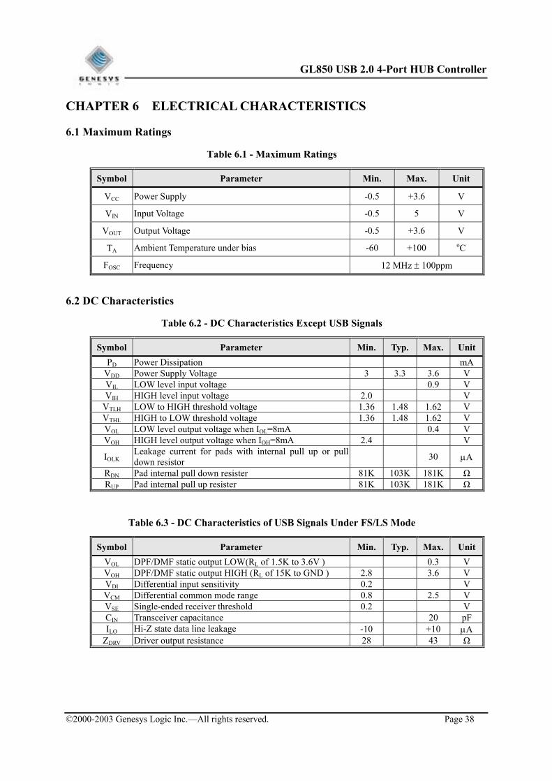
CHAPTER 6 ELECTRICAL CHARACTERISTICS
6.1 Maximum Ratings
Table 6.1 - Maximum Ratings
Symbol Parameter Min. Max. Unit
VCC Power Supply -0.5 +3.6 V
VIN Input Voltage -0.5 5 V
VOUT Output Voltage -0.5 +3.6 V
TA Ambient Temperature under bias -60 +100 oC
FOSC Frequency 12 MHz ± 100ppm
6.2 DC Characteristics
Table 6.2 - DC Characteristics Except USB Signals
Symbol Parameter Min. Typ. Max. UnitPD Power Dissipation mA
VDD Power Supply Voltage 3 3.3 3.6 V VIL LOW level input voltage 0.9 V VIH HIGH level input voltage 2.0 V
VTLH LOW to HIGH threshold voltage 1.36 1.48 1.62 V VTHL HIGH to LOW threshold voltage 1.36 1.48 1.62 V VOL LOW level output voltage when IOL=8mA 0.4 V VOH HIGH level output voltage when IOH=8mA 2.4 V
IOLK Leakage current for pads with internal pull up or pull down resistor 30 µA
RDN Pad internal pull down resister 81K 103K 181K Ω RUP Pad internal pull up resister 81K 103K 181K Ω
Table 6.3 - DC Characteristics of USB Signals Under FS/LS Mode
Symbol Parameter Min. Typ. Max. UnitVOL DPF/DMF static output LOW(RL of 1.5K to 3.6V ) 0.3 V VOH DPF/DMF static output HIGH (RL of 15K to GND ) 2.8 3.6 V VDI Differential input sensitivity 0.2 V VCM Differential common mode range 0.8 2.5 V VSE Single-ended receiver threshold 0.2 V CIN Transceiver capacitance 20 pF ILO Hi-Z state data line leakage -10 +10 µA
ZDRV Driver output resistance 28 43 Ω

GL850 USB 2.0 4-Port HUB Controller
©2000-2003 Genesys Logic Inc.—All rights reserved. Page 39
Table 6.4 - DC Characteristics of USB Signals Under HS Mode
Symbol Parameter Min. Typ. Max. Unit
VIL Low-level input voltage with HS termination resistor enabled, Pull-up resistor disconnected mV
VIH High-level input voltage with HS termination resistor enabled, Pull-up resistor disconnected mV
VIL Low-level input voltage with HS termination resistor enabled, Pull-up resistor connected mV
VIH High-level input voltage with HS termination resistor enabled, Pull-up resistor connected mV
VOL DPH/DMH static output LOW(RL of 1.5K to 3.6V ) 0.3 V
VOH DPH/DMH static output HIGH (RL of 15K to GND ) 2.8 3.6 V
CIN Transceiver capacitance 20 pF ILO Hi-Z state data line leakage -10 +10 µA
ZDRV Driver output resistance for USB2.0 HS Ω

GL850 USB 2.0 4-Port HUB Controller
©2000-2003 Genesys Logic Inc.—All rights reserved. Page 40
CHAPTER 7 PACKAGE DIMENSION
16
CONTROL DIMENSIONS ARE IN MILLIMETERS.
SYMBOL MILLIMETER INCHMIN. NOM. MAX. MAX.MIN. NOM.
AA1A2D
D1E
E1
R2R1
cL
L1Sbe
aaabbbcccddd
D2E2
TOLERANCES OF FORM AND POSITION
12.00 BASIC12.00 BASIC10.00 BASIC10.00 BASIC
0.472 BASIC0.472 BASIC0.393 BASIC0.393 BASIC
0.051.35 1.40
1.600.151.45
00
1111
3.5
1212
7
1313
0.080.08
0.20 0.0030.003
0.00800
1111
3.5
1212
7
1313
0.0630.0060.0570.055
0.0020.053
0.200.200.080.08
0.0080.0080.0030.003
0.50 BASIC
7.50 BASIC7.50 BASIC
0.020 BASIC
0.295 BASIC0.295 BASIC
1.00 REF 0.039 REF
0.090.45
0.200.17
0.60
0.20
0.200.75
0.27
0.0040.018
0.0080.007
0.024
0.008
0.0080.030
0.011
0-
02-03-
01-NOTES :
1.
2.
DIMENSIONS D1 AND E1 DO NOT INCLUDE MOLD PROTRUSION. ALLOWABLE PROTRUSION IS 0.25 mm PER SIDE. D1 AND E1 ARE MAXIMUM PLASTIC BODY SIZE
DIMENSIONS INCLUDING MOLD MISMATCH.
DIMENSION b DOES NOT INCLUDE DAMBAR PROTRUSION. ALLOWABLE DAMBAR PROTRUSION SHALL NOT CAUSE THE LEAD WIDTH TO EXCEED THE MAXIMUM b DIMENSION BY MORE THAN 0.08mm. DAMBAR CAN NOT BE LOCATED ON THE LOWER RADIUS OR THE FOOT. MINIMUM SPACE BETWEEN PROTRUSION AND AN ADJACENT LEAD IS 0.07mm.
SEATING PLANE
e
b
4X
4X
64
1
17
32
3348
49
GAGE PLANE
R1
R2
0.25mm
S L
03-
02-
H
E E1 E2
A
A B DCaaa
BA DHbbb
ddd M C BA s sD
B
D1
D2
D
D
A
A2A1
0.05
S
L1
c
01-
0- C
Cccc
Figure 7.1 - GL850 64 Pin LQFP Package