Embed Size (px)
Citation preview
For Single–Line Parallel Automatic Lubrication Systems
Maximum Working Pressure: 3500 psi (24 MPa, 241 bar)
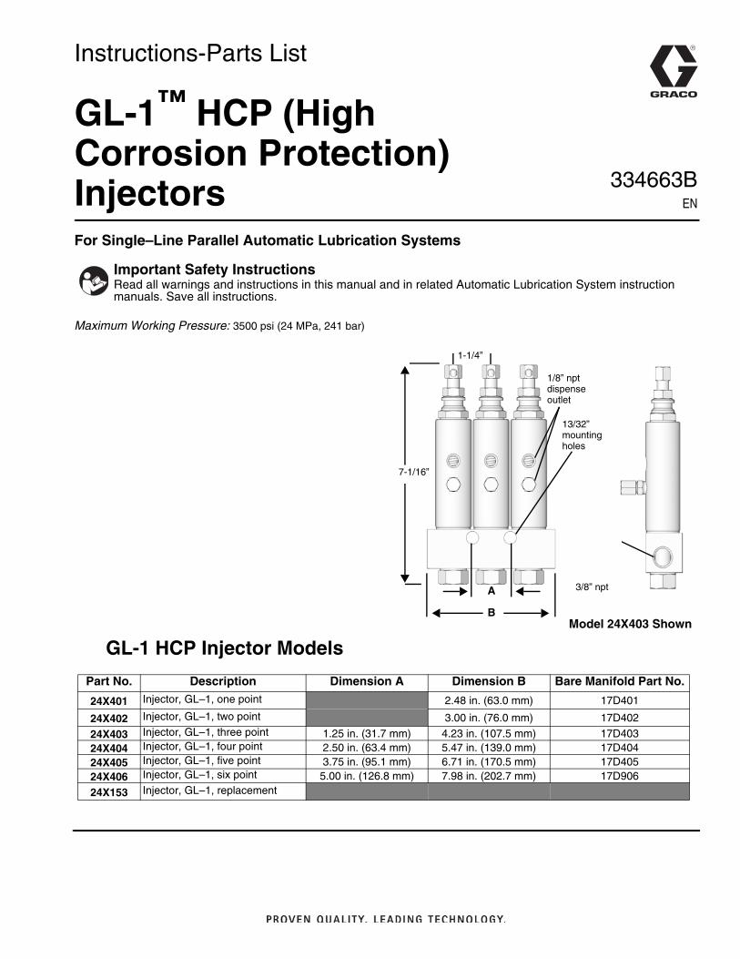
GL-1 HCP Injector Models
Important Safety InstructionsRead all warnings and instructions in this manual and in related Automatic Lubrication System instruction manuals. Save all instructions.
1-1/4”
7-1/16”
A
B
1/8” nptdispenseoutlet
13/32”mountingholes
3/8” npt
Model 24X403 Shown
Part No. Description Dimension A Dimension B Bare Manifold Part No.
24X401 Injector, GL–1, one point 2.48 in. (63.0 mm) 17D401
24X402 Injector, GL–1, two point 3.00 in. (76.0 mm) 17D402
24X403 Injector, GL–1, three point 1.25 in. (31.7 mm) 4.23 in. (107.5 mm) 17D40324X404 Injector, GL–1, four point 2.50 in. (63.4 mm) 5.47 in. (139.0 mm) 17D40424X405 Injector, GL–1, five point 3.75 in. (95.1 mm) 6.71 in. (170.5 mm) 17D40524X406 Injector, GL–1, six point 5.00 in. (126.8 mm) 7.98 in. (202.7 mm) 17D906
24X153 Injector, GL–1, replacement
Instructions-Parts List
GL-1™ HCP (High Corrosion Protection) Injectors 334663B
EN
Warnings
2 334663B
WarningsThe following warnings are for the setup, use, grounding, maintenance, and repair of this equipment. The exclamation point symbol alerts you to a general warning and the hazard symbols refer to procedure-specific risks. When these symbols appear in the body of this manual or on warning labels, refer back to these Warnings. Product-specific hazard symbols and warnings not covered in this section may appear throughout the body of this manual where applicable.
+
SKIN INJECTION HAZARD High-pressure fluid from injector, hose leaks, or ruptured components will pierce skin. This may look like just a cut, but it is a serious injury that can result in amputation. Get immediate surgical treatment.• Do not put your hand over the fluid outlet.• Do not stop or deflect leaks with your hand, body, glove, or rag.• Relieve pressure before cleaning, checking, or servicing equipment. • Tighten all fluid connections before operating the equipment.
PERSONAL PROTECTIVE EQUIPMENTWear appropriate protective equipment when in the work area to help prevent serious injury, including eye injury, hearing loss, inhalation of toxic fumes, and burns. This protective equipment includes but is not limited to:• Protective eyewear, and hearing protection. • Respirators, protective clothing, and gloves as recommended by the fluid and solvent manufacturer.
CALIFORNIA PROPOSITION 65This product contains a chemical known to the State of California to cause cancer, birth defects or other reproductive harm. Wash hands after handling.
WARNING
Warnings
334663B 3
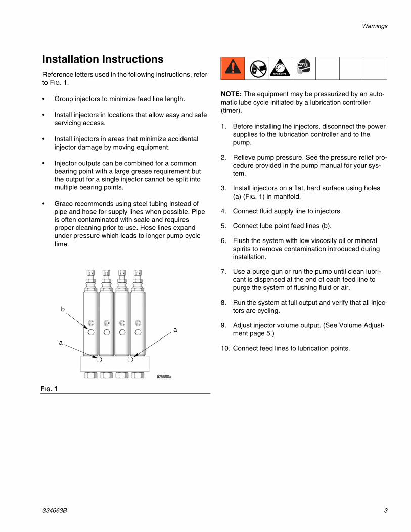
Installation InstructionsReference letters used in the following instructions, refer to FIG. 1.
• Group injectors to minimize feed line length.
• Install injectors in locations that allow easy and safe servicing access.
• Install injectors in areas that minimize accidental injector damage by moving equipment.
• Injector outputs can be combined for a common bearing point with a large grease requirement but the output for a single injector cannot be split into multiple bearing points.
• Graco recommends using steel tubing instead of pipe and hose for supply lines when possible. Pipe is often contaminated with scale and requires proper cleaning prior to use. Hose lines expand under pressure which leads to longer pump cycle time.
NOTE: The equipment may be pressurized by an auto-matic lube cycle initiated by a lubrication controller (timer).
1. Before installing the injectors, disconnect the power supplies to the lubrication controller and to the pump.
2. Relieve pump pressure. See the pressure relief pro-cedure provided in the pump manual for your sys-tem.
3. Install injectors on a flat, hard surface using holes (a) (FIG. 1) in manifold.
4. Connect fluid supply line to injectors.
5. Connect lube point feed lines (b).
6. Flush the system with low viscosity oil or mineral spirits to remove contamination introduced during installation.
7. Use a purge gun or run the pump until clean lubri-cant is dispensed at the end of each feed line to purge the system of flushing fluid or air.
8. Run the system at full output and verify that all injec-tors are cycling.
9. Adjust injector volume output. (See Volume Adjust-ment page 5.)
10. Connect feed lines to lubrication points.
FIG. 1
a
a
b
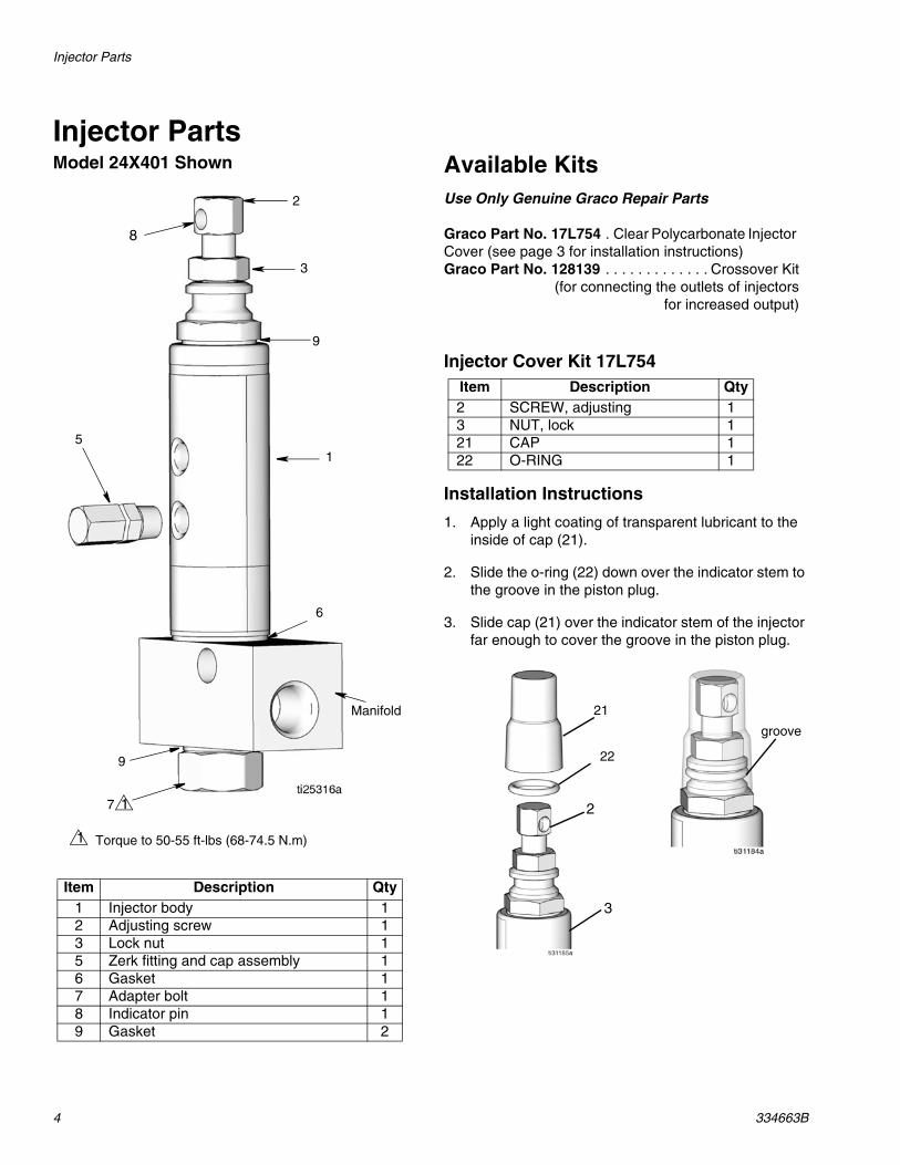
Injector Parts
4 334663B
Injector PartsModel 24X401 Shown Available Kits
Use Only Genuine Graco Repair Parts
Graco Part No. 17L754 . Clear Polycarbonate Injector Cover (see page 3 for installation instructions)Graco Part No. 128139 . . . . . . . . . . . . . Crossover Kit
(for connecting the outlets of injectors for increased output)
Injector Cover Kit 17L754
Installation Instructions
1. Apply a light coating of transparent lubricant to the inside of cap (21).
2. Slide the o-ring (22) down over the indicator stem to the groove in the piston plug.
3. Slide cap (21) over the indicator stem of the injector far enough to cover the groove in the piston plug.
Item Description Qty1 Injector body 12 Adjusting screw 13 Lock nut 15 Zerk fitting and cap assembly 16 Gasket 17 Adapter bolt 18 Indicator pin 19 Gasket 2
2
9
1
6
Manifold
9
7
5
3
1
Torque to 50-55 ft-lbs (68-74.5 N.m)1
8
Item Description Qty2 SCREW, adjusting 13 NUT, lock 121 CAP 122 O-RING 1
21
22
groove
2
3
334663B 5
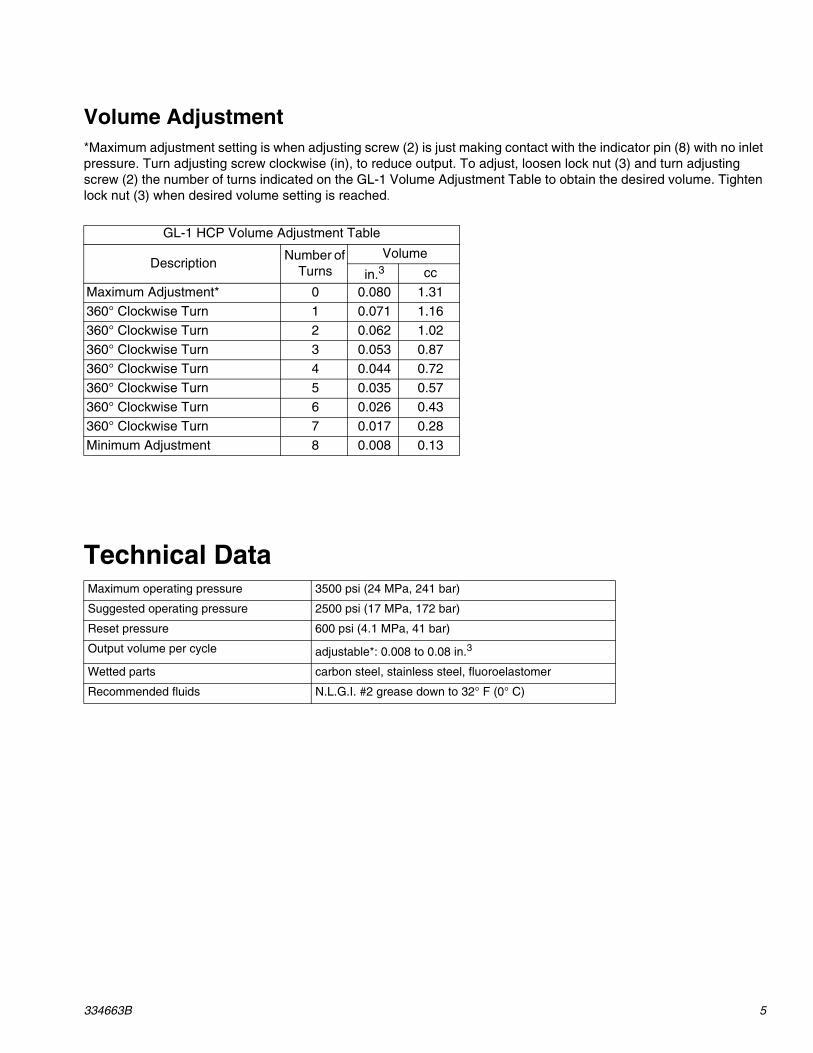
Volume Adjustment *Maximum adjustment setting is when adjusting screw (2) is just making contact with the indicator pin (8) with no inlet pressure. Turn adjusting screw clockwise (in), to reduce output. To adjust, loosen lock nut (3) and turn adjusting screw (2) the number of turns indicated on the GL-1 Volume Adjustment Table to obtain the desired volume. Tighten lock nut (3) when desired volume setting is reached.
Technical Data
GL-1 HCP Volume Adjustment Table
DescriptionNumber of
TurnsVolume
in.3 cc
Maximum Adjustment* 0 0.080 1.31
360° Clockwise Turn 1 0.071 1.16
360° Clockwise Turn 2 0.062 1.02
360° Clockwise Turn 3 0.053 0.87
360° Clockwise Turn 4 0.044 0.72
360° Clockwise Turn 5 0.035 0.57
360° Clockwise Turn 6 0.026 0.43
360° Clockwise Turn 7 0.017 0.28
Minimum Adjustment 8 0.008 0.13
Maximum operating pressure 3500 psi (24 MPa, 241 bar)
Suggested operating pressure 2500 psi (17 MPa, 172 bar)
Reset pressure 600 psi (4.1 MPa, 41 bar)
Output volume per cycle adjustable*: 0.008 to 0.08 in.3
Wetted parts carbon steel, stainless steel, fluoroelastomer
Recommended fluids N.L.G.I. #2 grease down to 32° F (0° C)
All written and visual data contained in this document reflects the latest product information available at the time of publication. Graco reserves the right to make changes at any time without notice.
Original instructions. This manual contains English. MM 334663
Graco Headquarters: MinneapolisInternational Offices: Belgium, China, Japan, Korea
GRACO INC. AND SUBSIDIARIES • P.O. BOX 1441 • MINNEAPOLIS MN 55440-1441 • USA
Copyright 2015, Graco Inc. All Graco manufacturing locations are registered to ISO 9001.www.graco.comNovember 2017
Graco Standard WarrantyGraco warrants all equipment referenced in this document which is manufactured by Graco and bearing its name to be free from defects in material and workmanship on the date of sale to the original purchaser for use. With the exception of any special, extended, or limited warranty published by Graco, Graco will, for a period of twelve months from the date of sale, repair or replace any part of the equipment determined by Graco to be defective. This warranty applies only when the equipment is installed, operated and maintained in accordance with Graco’s written recommendations.
This warranty does not cover, and Graco shall not be liable for general wear and tear, or any malfunction, damage or wear caused by faulty installation, misapplication, abrasion, corrosion, inadequate or improper maintenance, negligence, accident, tampering, or substitution of non-Graco component parts. Nor shall Graco be liable for malfunction, damage or wear caused by the incompatibility of Graco equipment with structures, accessories, equipment or materials not supplied by Graco, or the improper design, manufacture, installation, operation or maintenance of structures, accessories, equipment or materials not supplied by Graco.
This warranty is conditioned upon the prepaid return of the equipment claimed to be defective to an authorized Graco distributor for verification of the claimed defect. If the claimed defect is verified, Graco will repair or replace free of charge any defective parts. The equipment will be returned to the original purchaser transportation prepaid. If inspection of the equipment does not disclose any defect in material or workmanship, repairs will be made at a reasonable charge, which charges may include the costs of parts, labor, and transportation.
THIS WARRANTY IS EXCLUSIVE, AND IS IN LIEU OF ANY OTHER WARRANTIES, EXPRESS OR IMPLIED, INCLUDING BUT NOT LIMITED TO WARRANTY OF MERCHANTABILITY OR WARRANTY OF FITNESS FOR A PARTICULAR PURPOSE.
Graco’s sole obligation and buyer’s sole remedy for any breach of warranty shall be as set forth above. The buyer agrees that no other remedy (including, but not limited to, incidental or consequential damages for lost profits, lost sales, injury to person or property, or any other incidental or consequential loss) shall be available. Any action for breach of warranty must be brought within two (2) years of the date of sale.
GRACO MAKES NO WARRANTY, AND DISCLAIMS ALL IMPLIED WARRANTIES OF MERCHANTABILITY AND FITNESS FOR A PARTICULAR PURPOSE, IN CONNECTION WITH ACCESSORIES, EQUIPMENT, MATERIALS OR COMPONENTS SOLD BUT NOT MANUFACTURED BY GRACO. These items sold, but not manufactured by Graco (such as electric motors, switches, hose, etc.), are subject to the warranty, if any, of their manufacturer. Graco will provide purchaser with reasonable assistance in making any claim for breach of these warranties.
In no event will Graco be liable for indirect, incidental, special or consequential damages resulting from Graco supplying equipment hereunder, or the furnishing, performance, or use of any products or other goods sold hereto, whether due to a breach of contract, breach of warranty, the negligence of Graco, or otherwise.
FOR GRACO CANADA CUSTOMERSThe Parties acknowledge that they have required that the present document, as well as all documents, notices and legal proceedings entered into, given or instituted pursuant hereto or relating directly or indirectly hereto, be drawn up in English. Les parties reconnaissent avoir convenu que la rédaction du présente document sera en Anglais, ainsi que tous documents, avis et procédures judiciaires exécutés, donnés ou intentés, à la suite de ou en rapport, directement ou indirectement, avec les procédures concernées.
Graco Information For the latest information about Graco products, visit www.graco.com.
For patent information, see www.graco.com/patents.
TO PLACE AN ORDER, contact your Graco distributor or call to identify the nearest distributor.Phone: 612-623-6928 or Toll Free: 1-800-533-9655, Fax: 612-378-3590