Embed Size (px)
Citation preview

W-14
W-13
W-0
9
W-1
1
W-1
2
W-0
8
W-1
0
W-05
W-0
01
W-0
4
W-0
2
W-0
3
D-06
D-0
7
J01F
HB
01
HB01
TG01
J01A
J01B
J01
J02E
J02
J03C
R01
J03
J01C
J02A
J02B
J03B
R01A
J03A
J01F
HB01
HB
01
TG01A
J01B
J01A
J01D
J02A
J02C
J03B
R01A
J03A
J01E
J02E
J02D
J03C
R01
J03
T01
7900
7900
16700
16700
G J G
AR
DN
ER
- PA
UL &
CA
RE
N H
EN
DE
RS
ON
122 SE
A B
RE
EZE
LAN
E - W
HA
NG
AM
ATA
JOB
NO
12-42091
PLACEMAKERS�FRAM
E�AND�TRU
SS�THAM
ES/WHITIAN
GA
29�MOEW
AI�ROAD
���WHITIAN
GA���PH
ONE�(07)�867�2090
C=
CT400
m=
SING
LE MU
LTIGRIP
C=
PAIR O
F CT200'Sm
=PA
IR OF M
ULTIG
RIPS
C=
2 PAIRS O
F CT200'SX
=PA
IR OF CPC40'S
O=
90x47 JOIST H
AN
GER
X=
PAIR O
F CPC80'S
O=
120x47 JOIST H
AN
GER
X=
PAIR O
F CPC80'S & CT200'S
O=
190x47 JOIST H
AN
GER
N=
200mm
x 1mm
NA
ILON
PLATE
D=
165x95 JOIST H
AN
GER
N=
320mm
x 1mm
NA
ILON
PLATE
ALL TRU
SSES TO H
AV
E A PA
IR OF Z N
AILS FRO
M TRU
SS TO
TOP PLA
TE UN
LESS OTH
ERWISE SPECIFIED
. ALL U
NSPECIFIED
FIXIN
GS K
EY
TRUSS TO
TRUSS FIX
ING
S REQU
IRE FOU
R 90mm
NA
ILS.
C
C
C
C
OO
O
O
O
O
OO
OO
OO
O
O
O
OO
O
CT400'S
1890x47 JO
IST HA
NG
ERS320 x 1m
m N
AILO
N PLA
TES
4PA
IRS OF CT200'S
120x47 JOIST H
AN
GERS
MU
LTIGRIPS
PAIRS O
F CPC40'S190x47 JO
IST HA
NG
ERS64
PAIRS O
F Z NA
ILS
PAIRS O
F CPC80'S165x95 JO
IST HA
NG
ERS2
BAG
S OF PRO
DU
CT NA
ILS
FIXIN
GS Q
UA
NTITIES
1000
1000
1500
5480
2460
4500
1050
0
8200
Free
Sta
ndin
g D
eck
NO
T at
tach
ed N
ew B
uild
ing
Not
par
t of t
his
cont
ract
Soffi
t Lin
e
Handrail to Steps
W-0
4ar
ea 1
29m
2
1 A
ug
us
t 2
01
1
DE
PA
RT
ME
NT
OF
BU
I LD
I NG
AN
D H
OU
SI N
G
104
EX
TE
RN
AL
MO
I ST
UR
E
Acc
ep
tab
le S
olu
tio
n E
2/A
S1
CO
MM
EN
T:Sl
oped
hea
ds r
equi
re s
peci
fical
ly d
esig
ned
kick
-out
flash
ings
at
bott
om e
dges
of
head
fla
shin
gs.
Whe
re w
idth
out
lined
in P
arag
raph
9.1
.10.
1 ar
e be
yond
the
limits
for
sill
and
hea
d tr
imm
er f
ram
ing
in N
ZS 3
604
spec
ific
engi
neer
ing
desi
gn o
f th
e fr
amin
g is
req
uire
d.
Cer
tain
alu
min
ium
join
ery
sect
ions
and
inst
alla
tion
requ
irem
ents
may
not
be
able
to
mee
t th
e de
tails
of
this
Acc
epta
ble
Solu
tion,
esp
ecia
lly in
reg
ard
to w
indo
w
faci
ng c
over
, sill
sup
port
, win
dow
fix
ing,
and
sill
fla
shin
g
requ
irem
ents
. The
win
dow
det
ails
in t
hese
cas
es r
equi
re
spec
ific
desi
gn.
9.1.
10.2
Tre
atm
ent
of o
peni
ng
a) T
reat
men
t of
the
win
dow
ope
ning
s fo
r
dire
ct f
ixed
wal
l cla
ddin
gs s
hall
be a
s sh
own
in F
igur
e 72
A.
b) F
or d
irect
fix
ed c
ladd
ings
, win
dow
s an
d
door
s sh
all h
ave
a 5
mm
sta
nd-o
ff o
f
the
flang
e to
the
cla
ddin
g to
allo
w f
or a
ir
intr
usio
n to
the
trim
cav
ity f
or p
ress
ure
equa
lisat
ion.
Not
e th
at t
his
gap
is s
eale
d
or t
rimm
ed d
own
the
jam
bs, b
ut le
ft o
pen
alon
g th
e si
ll.c)
Win
dow
ope
ning
s fo
r w
all c
ladd
ings
ove
r
drai
ned
cavi
ties
shal
l be
as s
how
n in
Fig
ure
72B
. Not
e th
ere
shal
l be
no s
ill f
lash
ing.
d) F
or c
avity
fix
ed c
ladd
ings
, win
dow
s an
d
door
s sh
all f
inis
h ag
ains
t th
e cl
addi
ng,
exce
pt f
or f
lat
fibre
cem
ent
and
ply
clad
ding
s th
at r
equi
re a
5 m
m s
tand
-off
to
allo
w f
or s
eala
nt w
eath
er s
eals
bet
wee
n
faci
ngs
and
clad
ding
– e
g, F
igur
e 11
6.
e) M
ater
ials
for
fla
shin
gs s
hall
be s
elec
ted
from
Par
agra
ph 4
.0, T
able
7, a
nd T
able
20.
9.1.
10.3
Win
dow
and
doo
r he
ads
Win
dow
s an
d do
ors
shal
l inc
lude
hea
d
flash
ings
, fin
ishe
d to
the
wal
l und
erla
y as
show
n in
Fig
ure
71, b
y ei
ther
usi
ng f
lexi
ble
flash
ing
tape
, or
lapp
ing
an a
dditi
onal
laye
r of
wal
l und
erla
y ov
er t
he u
psta
nd. T
he a
dditi
onal
wal
l und
erla
y sh
all e
xten
d to
the
top
of
the
wal
l, or
to
the
near
est
lap
abov
e, a
nd b
e
lapp
ed u
nder
the
top
laye
r.
Gen
eral
sea
ling
of h
ead
flash
ing
Para
grap
hs 9
.1.7
, 9.1
.10.
3 an
d 9.
1.10
.4
Figu
re 7
1:
Am
end
5 A
ug 2
011
Am
end
5A
ug 2
011
Am
end
5A
ug 2
011
Existing Garage
Existing TimberDeck
Existing Concrete Pad
G.T
.G
.T.T.
V.
G.T
.
D.P.
D.P.
Stormwater Discharged to R.O.W.
G.J. Gardner. HOMES
COPYRIGHT: This drawing remains the property of G.J. Gardner homes and isprovided for the use as described and may not be used or reproduced in whole orin part without written permission.
Propose New Home forPAUL & CAREN HENDERSON
LOT 25 DP 429036122 Sea Breeze LaneWhangamata
SCALE 1:200DRAWN RSSDATE 12/12
Job No
page 001
SITE PLAN
HOMES30
.98
28.9
7
12.00
18.00
6.30
6m P
rivac
y C
ircle
Existing Sewer Line and Site Connection
New Sewer Line
NoteBuilding Contractor to establish Boundary Line and ensure offset fromBoundary
Mains Water Connection
Power Telephone
R.O.W.to Sea Breeze LaneExterior H/C Shower
Existing Concrete PadBuilders to Site House Foundations Alongside
GENERAL NOTESSCOPE OF WORK:The work comprises the Project as outlinedon these drawings and described in theaccompanying specification.CONTRACT DOCUMENTS:The contract documents comprise theseDrawings and the accompanyingSpecification.DIMENSIONS AND LEVELS:All dimensions and levels are believed to bereasonably accurate. Any discrepancies areto be reported to the Owner (or theirappointed representative) so that his decisionmay be obtained before proceeding further.SITING OF BUILDING WORK:All Boundary pegs and services are to belocated before construction workcommences.N.Z. STANDARD SPECIFICATION:The NZ Building (Forms) Regulations 2004(and amendments), The NZ Building Code andNZS 3604:2011NZS 4229:1999 amendment No.1NZS 4218:2004 (Sept 2008 R values)Timber Framed Buildings shall be followed to thefull extent applicable consistent with theintent of the contract.NZBC Clauses:B1 StructureB2 DurabilityE1 Surface waterE2 External moistureE3 Internal moistureG1-G15 Services & FacilitiesH1 2007 Energy efficiency
DOCUMENTS ONSITESNZ HB 3604:2011GIB® EzyBraceTM FP June 2011GIB® Aqualine Wet Area Systems Mar 2007Gib Site Guide Jan 2010Linea Weatherboard Technical Specification - January 2012
CONTRACTORS NOTES1. Do not scale from drawing. Used figred dimension only. Check all dimensions on site before any manufacture or construction.2. No change to the design or substitution to any of the products or details without the designer's approval in writing, should the suppliers, contractors, builders, owners or any other party change the design and detail or product specified without the designer's approval in writing, shall be vested in the person who made the change.3.Should any discrepancies between drawings or specification be found the designer shall be contacted immediately for clarification before proceeding with the works.4.All levels and dimensions to be verified on site by contractors before commencement of the works.5.Safe site and OSH practicies to be maintained throughout period of consruction. Danger signs and adequate barriers in place.
SITE INFORMATION
Site AreaHouse Area Roof AreaPorchExisting GarageSite Cover
Site DataExposure ZoneWind ZoneEarthquake ZoneClimate ZoneFlood HazardBuilding DataLive Floor loadsBuilding Height
552m2
121.8m2
162.9m2
3.1m2
49.5m34.6%
Good Ground; Geotechnical Report by GDC Ref:319Zone 1MediumZone 1Zone 1LowA1 Self Contained Dwelling1.5kPa4.8m
PLUMBING NOTES:All Plumbing and Drainage Work to Completed byRegistered Plumbers and Drainlayers for ComplianceBuilding Code ClausesG12 - Water SupplyG13 - Foul WaterCompliance UsingG12 AS1G13 AS1, AS/NZS 3500.540mm Wastewater Drains to Discharge to Gully Traps min fal 1:4065mm Wastewater Drains to Discharge Direct to Main Drains min fall 1:40WC Drains to be 100mm with 1:60 fallVents 80mmAll Drain Lengths over 10m to have 50mm VentsRelief Gully Vent to have Water Tap Situated Above Stormwater Downpipes fixed 300mm from extenal corners of buildingInground Stormwater Pipe 100mm uPVC min fall 1:60
170991
CONTENTS
001 SITE PLAN002 ELEVATIONS003 FLOOR PLAN004 FOUNDATION PLAN005 TRUSS PLAN 006 LINTEL PLAN007 BRACING008 CROSS SECTION009 CONSTRUCTION DETAILS010 LINEA DETAILS011 LINEA DETAILS012 WINDOW DETAILS013 PANEL FIXING014 BRACING DEMAND015 BRACING VALUES

2500
450
500
1500
Eas
t Bou
ndar
y Li
ne
500
EAST ELEVATION
SOUTH ELEVATION
NORTH ELEVATION
WEST ELEVATION
Monier Horizon Flat Concrete Tile RoofColorsteel Metal FasciaColorsteel External Gutter80mm pvc DownpipesHardies Linea Weatherboard CladdingDouble Glazed Powder Coat Aluninium Doors and WindowsMain Entry Plantation Fibreglass DoorSeries 200 Concrete Block FoundationEntry Deck Main Deck by Others
G.J. Gardner. HOMES
COPYRIGHT: This drawing remains the property of G.J. Gardner homes and isprovided for the use as described and may not be used or reproduced in whole orin part without written permission.
Proposed New Home forPAUL & CAREN HENDERSON
LOT 25 DP 429036122 Sea Breeze LaneWhangamata
SCALE 1:100DRAWN RSSDATE 12/12
Job No
page 002ELEVATIONS
F.F.L.
F.F.L.
Existing Concrete PadBuilders to Site House Foundations Alongside
External H/C ShowerDischarge to Concrete Pad
EXTERNAL MOISTURE E2 RISK MATRIXWEATHERTIGHT RISK ASSESMENT
HENDERSON HOUSELot 25. DP 122 Sea Breeze Lane, Whangamata
Aspect ALLRisk Factor LOW MEDIUM HIGH V. HIGH sub TotalWind Zone medium 0 0 1 2 0Number of Stories one 0 1 2 4 0Roof/Wall Intersection Design none 0 1 3 4 0Eaves Width 600 0 1 2 5 1Envelope Complexity simple 0 1 3 6 0Deck Design not attached 0 2 4 6 0Total Risk Score 1SUBMIT Scyon Linea 180 Weatherboard DIRECT FIXED TO FRAME
HOMES
Entry
170991

W-1
4W
-13
W-09W-11W-12 W-08W-10
W-0
5
W-001
W-04W-02 W-03
D-0
6
D-07
16700
6645
90
1200
90
2875
90
3890 1550
9090
7900
2020
90
1900
3620
2910
90
1100
1210
90
2410
9090
90
7410
90
3420
90
2000
90
3420
90 90700
90
1542
90
2120
90
700
90
1100
90
600
3020
9090
90
760
Cav
. Sld
er76
0
2/610 760 760
760 760
760
760
90
690
650x650Fridge72
560
0
600KITCHENDINING
LIVING BED 3
UTILITY
HWC STORE
BATHROM BED 2
BED 1
LAU
ND
RY
ENSUITE
W/ROBE
W/R
OBE
PAN
TRY
WINDOW SCHEDULEW-OO1 45000x2130 2 Panel R/Slider StackerW-002 2000x1300 1 Awning, 1 FixedW-003 760x800 AwningW-004 2000x1300 1 Awning, 1 FixedW-005 2000x400 2x AwningD-006 800x2130 Inward Opening Entry DoorD-007 800x2130 Inward Opening Entry DoorW-008 900x1200 AwningW-009 2000x1300 1 Awning, 1 FixedW-010 1600x1100 1 Awning, 1 FixedW-011 1000x400 AwningW-012 1000x400 AwningW-013 2000x1300 1 Awning, 1 FixedW-014 2400x2130 Ranchslider
WALK-INW/ROBE
G.J. Gardner. HOMES
COPYRIGHT: This drawing remains the property of G.J. Gardner homes and isprovided for the use as described and may not be used or reproduced in whole orin part without written permission.
Propose New Home forPAUL & CAREN HENDERSON
LOT 25 DP 429036122 Sea Breeze LaneWhangamata
SCALE 1:100DRAWN RSSDATE 12/12
Job No
page 003FLOOR PLAN
1mx1m Athena Seville Shower with Scopedor Safety glass doorEnglefield Sorrento II 1675mm BathSt.Micheal 900mm Riva VanityVenecia WC
1mx1m Athena Seville Shower with Scopedor Safety glass doorSt.Micheal 900mm Riva Vanity
Venecia WC
Kitchen Window Sill Height to be determined onsite, aligned with final Rangehood level
Selected Timber Deck
Timber Slab StepsTimber Handrail
PORCH
Soffit Line
CIRCULATION
Exterior H/C Shower
HOMES
Smoke Alarm
Hot Water Cylinder180ltr Storage Heater with Seismic ConstraintFixed 100mm from top and bottom with 6kN Straps with 8mm Coach Screws with 30x2mm Washer.Refer Figure 14 Clause G12 Water Supply - Third EditionSeismic Restraint NZS1170.5.2004Standard HWC Mains Pressure Valve Pack with standardFit Temporing Valve and Cold Water Expansion Valve to Existing Clinder20mm Copper Pipe FittingsRefer Figure 8 Clause G12 Water Supply - Third Edition70mm Edged Galvanised Leak tray Below Cylinder
Wet AreasGib Aqua LiningsRefer GIB® Aqualine Wet Area Systems Mar 2007
170991

area 129m2
7900
2200
1900
3800
16700
1600
18474
300
200
500
50
100
60
665 meshdamp proof membrane
2/D12 bars with R6 ties at 600 crs300x200 17.5 mpa concrete
D12 bar
sand blinding
conc. slab
D12 @ 600 crs bent to give 600 lap with mesh
Weatherboard Lap
Natural Ground Level
Compacted Fill <70->300mm
Selected Aluninium Joinery
90x35 Premium Decking
190x45 H3.2 Joists @600crs
190x45 H3.2 Ribbon Board
M12 Masonry Anchor
Malthoid
Series 190 Block
G.J. Gardner. HOMES
COPYRIGHT: This drawing remains the property of G.J. Gardner homes and isprovided for the use as described and may not be used or reproduced in whole orin part without written permission.
Propose New Home forPAUL & CAREN HENDERSON
LOT 25 DP 429036122 Sea Breeze LaneWhangamata
SCALE 1:20,1:100DRAWN RSSDATE 12/12
Job No
page 004FOUNDATIONS
HOMES
300 Strip Footing
Shrinkage Control Joints25x5 Cuts to ConcreteNZS 3604:2011 Clause 7.5.8.6
Supplementry Reinforcing2/D10, 1.2m Long
100mm 20mpa Concrete Floor668 MeshDCMSand BlindingCompacted Fill <70->300mmGood Ground
170991
FOOTING DETAIL
DECK FIXING DETAIL
FOUNDATION PLAN

J01F
HB01
HB01
TG
01
J01A
J01B
J01
J02E
J02
J03C
R01
J03
J01C
J02A
J02B
J03B
R01A
J03A
J01F
HB01
HB01
TG
01A
J01B
J01A
J01D
J02A
J02C
J03B
R01A
J03A
J01E
J02E
J02D
J03C
R01
J03
T01
7900
7900
16700
16700
G J GARDNER - PAUL & CAREN HENDERSON122 SEA BREEZE LANE - WHANGAMATAJOB NO 12-42091 PLACEMAKERS�FRAME�AND�TRUSS�THAMES/WHITIANGA
29�MOEWAI�ROAD���WHITIANGA���PHONE�(07)�867�2090
C = CT400 m = SINGLE MULTIGRIPC = PAIR OF CT200'S m = PAIR OF MULTIGRIPSC = 2 PAIRS OF CT200'S X = PAIR OF CPC40'SO = 90x47 JOIST HANGER X = PAIR OF CPC80'SO = 120x47 JOIST HANGER X = PAIR OF CPC80'S & CT200'SO = 190x47 JOIST HANGER N = 200mm x 1mm NAILON PLATED = 165x95 JOIST HANGER N = 320mm x 1mm NAILON PLATE
ALL TRUSSES TO HAVE A PAIR OF Z NAILS FROM TRUSS TOTOP PLATE UNLESS OTHERWISE SPECIFIED. ALL UNSPECIFIED
FIXINGS KEY
TRUSS TO TRUSS FIXINGS REQUIRE FOUR 90mm NAILS.
C C
CC
O O O
O
O
O
OOO
OOO
O
O
O
O O O
CT400'S 18 90x47 JOIST HANGERS 320 x 1mm NAILON PLATES4 PAIRS OF CT200'S 120x47 JOIST HANGERS MULTIGRIPS
PAIRS OF CPC40'S 190x47 JOIST HANGERS 64 PAIRS OF Z NAILSPAIRS OF CPC80'S 165x95 JOIST HANGERS 2 BAGS OF PRODUCT NAILS
FIXINGS QUANTITIES
ALL TRUSSES TO HAVE A PAIR OF Z NAILS FROM TRUSS TOTOP PLATE UNLESS OTHERWISE SPECIFIED. ALL UNSPECIFIEDTRUSS TO TRUSS FIXINGS REQUIRE FOUR 90mm NAILS.
G.J. Gardner. HOMES
COPYRIGHT: This drawing remains the property of G.J. Gardner homes and isprovided for the use as described and may not be used or reproduced in whole orin part without written permission.
Propose New Home forPAUL & CAREN HENDERSON
LOT 25 DP 429036122 Sea Breeze LaneWhangamata
SCALE DRAWN RSSDATE 12/12
Job No
page 005ROOFTRUSSES
HOMES
Note2/CT200
All Other Truss Fixing2/'Z' nails
170991

G J GARDNER - PAUL & CAREN HENDERSON122 SEA BREEZE LANE - WHANGAMATAJOB NO 12-42091
2/29
0x45
2145x45151/295x85
295x85 HYNE 17C AS LINTEL
1315x20152/190x45
815x7752/140x45
1315x20152/240x45
415x
2015
2/19
0x45
2145
x900
2/1 4
0x45
2145x9002/140x45
1215x9152/140x45
1315x20152/240x45
1115x16152/190x45
415x10152/140x45
415x10152/140x45
1315
x 201
52 /
190x
4520
15x 2
415
2 /24
0x45
LINTEL AND BEAM PLAN
ALL LINTELS ON THIS LAYOUT ARE MSG8 GRADEAND SELECTED FROM THE MITEK GANGLAM MANUAL OR HYNE BEAMS WHICH ARE DESIGNEDWITH DESIGN IN HYNE V4 SOFTWARE OR HYSPANSWHICH ARE DESIGNED WITH DESIGN IT SOFTWAREUNLESS SPECIFIED OTHERWISE.
SOME INTERNAL WALLS SHOWN FOR THEPURPOSE OF WINDOW LOCATIONS ONLY.
PLACEMAKERS�FRAME�AND�TRUSS�THAMES/WHITIANGA29�MOEWAI�ROAD���WHITIANGA���PHONE�(07)�867�2090
Lintel Fixing 7.5kN All other Lintels 3/90x3.15 end nailed
G.J. Gardner. HOMES
COPYRIGHT: This drawing remains the property of G.J. Gardner homes and isprovided for the use as described and may not be used or reproduced in whole orin part without written permission.
Propose New Home forPAUL & CAREN HENDERSON
LOT 25 DP 429036122 Sea Breeze LaneWhangamata
SCALE DRAWN RSSDATE 12/12
Job No
page 006
LINTEL PLAN
HOMES 170991
LINTEL PLAN
W-1
4W
-13
W-09W-11W-12 W-08W-10
W-0
5
W-001
W-04W-02 W-03
D-0
6
D-07
GS1-N 3000
GS
1-N
360
0
GS1-N 1600 GS1-N 900
GS1-N 2400
GS
1-N
360
0
GS
1-N
900
GS
1-N
200
0
GS
1-N
160
0
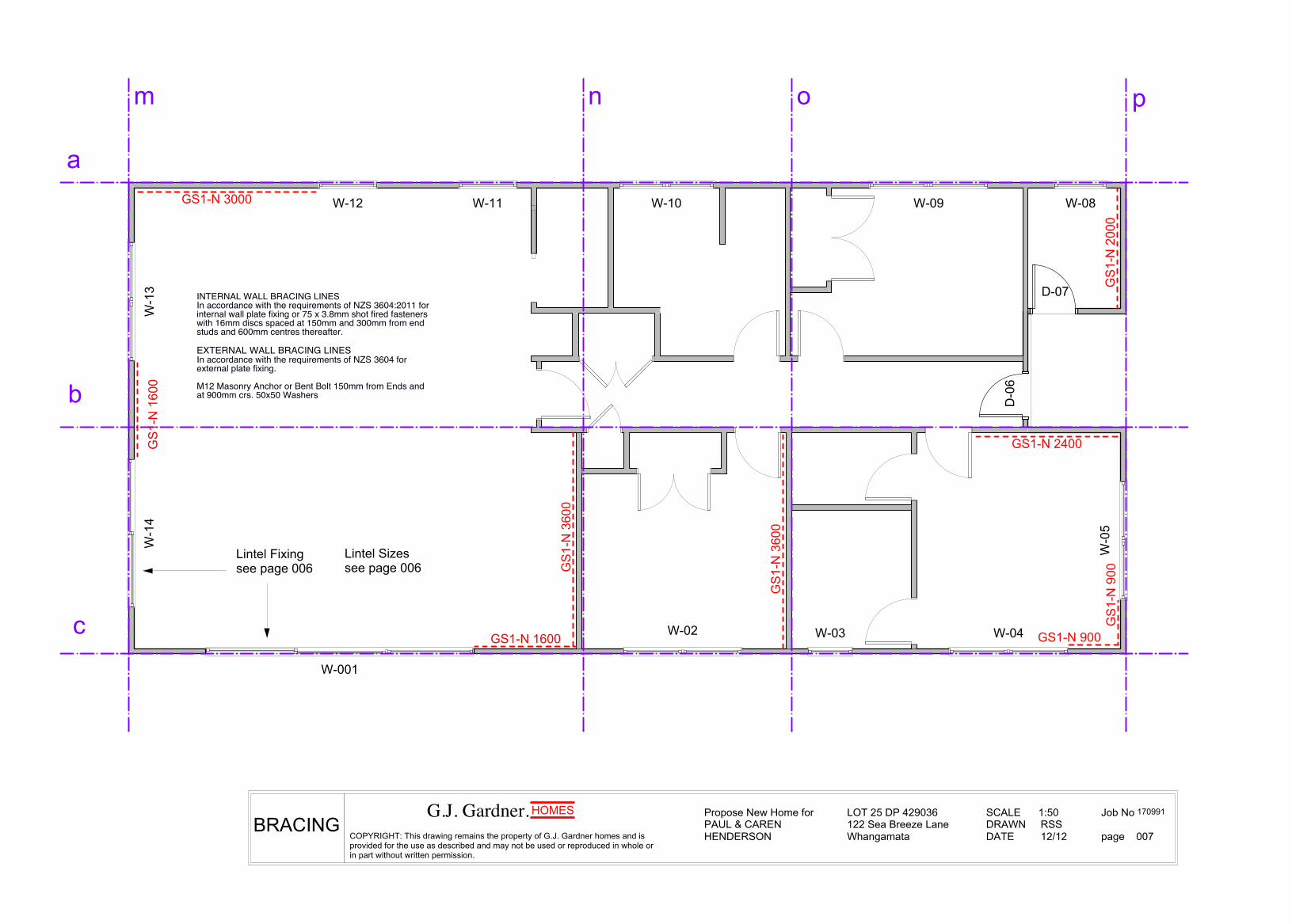
INTERNAL WALL BRACING LINESIn accordance with the requirements of NZS 3604:2011 forinternal wall plate fixing or 75 x 3.8mm shot fired fastenerswith 16mm discs spaced at 150mm and 300mm from endstuds and 600mm centres thereafter.
EXTERNAL WALL BRACING LINESIn accordance with the requirements of NZS 3604 forexternal plate fixing.
M12 Masonry Anchor or Bent Bolt 150mm from Ends andat 900mm crs. 50x50 Washers
a
b
c
m n o p
Lintel Fixing see page 006
G.J. Gardner. HOMES
COPYRIGHT: This drawing remains the property of G.J. Gardner homes and isprovided for the use as described and may not be used or reproduced in whole orin part without written permission.
Propose New Home forPAUL & CAREN HENDERSON
LOT 25 DP 429036122 Sea Breeze LaneWhangamata
SCALE 1:50DRAWN RSSDATE 12/12
Job No
page 007BRACING
HOMES
Lintel Sizessee page 006
170991

2420
2130
600
100mm 20mpa Concrete Floor668 MeshDCMSand BlindingCompacted Fill <70->300mmGood Ground
Truss Frame Roof
Trusses @900crssee page 005 for details and wall to truss fixings
2/'z' nails to truss endCT200's to lines TGO1A
Porch
Deck Fixing see page 004 for Details
35mm Rondo Ceiling Battens
13mm Gib
90x45 H1.2 SG 8 Wall Framing
90x45 H3.2 Bottom Plates
10mm Gib to walls10mm Gib Aqua to wet areas
NZBC CLAUSE H1 ENERGY EFFICIENCY
Ceiling Insulation Value R3.2Wall Insulation Value R2.2
Note;Roof Insulation is installed over wall frameensure a 25mm air is formed betweenroof underlay and insulation material.
500
250Soffit see page 009 for details
Footingssee page 004 for details
Linea Sill and Jambsee page 010 for details
Series 190Block Foundation
Monier - Horizon FlatConcrete Tile Roofing fixed to;
50x50 Battens over
Heavy Weight Building Paper
Colorsteel Metal Fascia Colorsteel External Gutter
90x45 H1.2 SG 8 Ceiling Frame @600crs
Selected Hardies Soffit lining
180 Scyon Linea WeatherboardsDirect Fixed overLight Weight Building Wrap
90x35 H3.2 Decking
190x45 H3.2 Deck Frame @600crs
M12 Masonry Anchor50x50 Washer
Selected Aluminium Joinery
Lint
el H
eigh
t
G.J. Gardner. HOMES
COPYRIGHT: This drawing remains the property of G.J. Gardner homes and isprovided for the use as described and may not be used or reproduced in whole orin part without written permission.
Propose New Home forPAUL & CAREN HENDERSON
LOT 25 DP 429036122 Sea Breeze LaneWhangamata
SCALE 1:25DRAWN RSSDATE 12/12
Job No
page 008
TYPICALCROSS SECTION
HOMES 170991

50 Min. Overhang
600
1 A u g u s t 2 0 1 1 D E PA R T M E N T O F B U I L D I N G A N D H O U S I N G66
E X T E R N A L M O I S T U R E Acceptable Solution E2/AS1
Figure 28:
Roof/wall ridge for masonry tile Paragraph 8.2.6
Figure 27:
Valley for masonry tile Paragraphs 8.2.6 and 8.1.6.2
8.2.7 Penetrations
Penetrations shall be flashed as shown in Figure 29 to Figure 31.
Holes in tiles for pipe penetrations shall be machine-cut to minimise the size of the hole.
Figure 29:
Pipe penetration for masonry tile Paragraph 8.2.7
Amend 2 Jul 2005
Amend 2 Jul 2005
Amend 2 Jul 2005
Amend 5 Aug 2011
Amend 5 Aug 2011
Amend 5 Aug 2011
Amend 5 Aug 2011
G.J. Gardner. HOMES
COPYRIGHT: This drawing remains the property of G.J. Gardner homes and isprovided for the use as described and may not be used or reproduced in whole orin part without written permission.
Propose New Home forPAUL & CAREN HENDERSON
LOT 25 DP 429036122 Sea Breeze LaneWhangamata
SCALE 1:2, 1:10DRAWN RSSDATE 12/12
Job No
page 009
CONSTRUCTIONDETAILS
HOMES
Monier - Horizon FlatConcrete Tile Roofing fixed to;
50x50 Battens over
Heavy Weight Building Paper Paper Lapped over Fascia
Colorsteel Metal Fascia Colorsteel External Gutter
90x45 H1.2 SG 8 Soffit Frame
Selected Hardies Soffit liningSee page 012 for Weatherboard to Soffit joint details
Rondo Batten @600crs
13mm Ceiling Gib
Double Top Plate to Frame
Truss Frame
Nail Plate to Truss
1 A u g u s t 2 0 1 1 D E PA R T M E N T O F B U I L D I N G A N D H O U S I N G104
E X T E R N A L M O I S T U R E Acceptable Solution E2/AS1
COMMENT:
Sloped heads require specifically designed kick-out flashings at bottom edges of head flashings.
Where width outlined in Paragraph 9.1.10.1 are beyond the limits for sill and head trimmer framing in NZS 3604 specific engineering design of the framing is required.
Certain aluminium joinery sections and installation requirements may not be able to meet the details of this Acceptable Solution, especially in regard to window facing cover, sill support, window fixing, and sill flashing requirements. The window details in these cases require specific design.
9.1.10.2 Treatment of opening
a) Treatment of the window openings for direct fixed wall claddings shall be as shown in Figure 72A.
b) For direct fixed claddings, windows and doors shall have a 5 mm stand-off of the flange to the cladding to allow for air intrusion to the trim cavity for pressure equalisation. Note that this gap is sealed or trimmed down the jambs, but left open along the sill.
c) Window openings for wall claddings over drained cavities shall be as shown in Figure 72B. Note there shall be no sill flashing.
d) For cavity fixed claddings, windows and doors shall finish against the cladding, except for flat fibre cement and ply claddings that require a 5 mm stand-off to allow for sealant weather seals between facings and cladding – eg, Figure 116.
e) Materials for flashings shall be selected from Paragraph 4.0, Table 7, and Table 20.
9.1.10.3 Window and door heads
Windows and doors shall include head flashings, finished to the wall underlay as shown in Figure 71, by either using flexible flashing tape, or lapping an additional layer of wall underlay over the upstand. The additional wall underlay shall extend to the top of the wall, or to the nearest lap above, and be lapped under the top layer.
General sealing of head flashing Paragraphs 9.1.7, 9.1.10.3 and 9.1.10.4
Figure 71:
Amend 5 Aug 2011
Amend 5Aug 2011
Amend 5Aug 2011
2/'z' nails to TrussSOFFIT DETAIL
170991

G.J. Gardner. HOMES
COPYRIGHT: This drawing remains the property of G.J. Gardner homes and isprovided for the use as described and may not be used or reproduced in whole orin part without written permission.
Propose New Home forPAUL & CAREN HENDERSON
LOT 25 DP 429036122 Sea Breeze LaneWhangamata
SCALE DRAWN RSSDATE 12/12
Job No
page 010WEATHERBOARDDETAILS
HOMES
METER BOX HEADMETER BOX JAMB
METER BOX SILLPIPE PENETRATION EXTERNAL MITRE CORNER
INTERNAL CORNER
170991

G.J. Gardner. HOMES
COPYRIGHT: This drawing remains the property of G.J. Gardner homes and isprovided for the use as described and may not be used or reproduced in whole orin part without written permission.
Propose New Home forPAUL & CAREN HENDERSON
LOT 25 DP 429036122 Sea Breeze LaneWhangamata
SCALE 1:2DRAWN RSSDATE 12/12
Job No
page 012
WINDOWDETAILS
HOMES
Soffit Frame
Lintel
10mm Gib
Selected Aluminium JoineryFitted to Soffit Lining
WindowFacing
Joinery Reveal
4.5mm Soffit
Packing Block
WINDOW JAMB
WINDOW HEAD
WINDOW SILL
170991
Sealant
Building Wrap

GIB ezyBrace® Systems
JUNe 2011
23FOR FURTHER INFORMATION VISIT WWW.GIB.CO.NZ OR PHONE THE GIB® INFORMATION HELPLINE 0800 100 442
Con
stru
ctio
n
GIB EzyBrace® System Specification – GS1-N
Specification Code
Minimum Length (m)
Lining requirement
GS1-N 0.4 Any 10mm or 13mm GIB® Standard Plasterboard to one side only
WALL FrAMInGWall framing to comply with;• NZBC B1 - Structure; AS1 Clause 3 Timber (NZS
3604:2011)• NZBC B2 - Durability AS1 Clause 3.2 Timber (NZS 3602)Framing dimensions and height as determined by NZS 3604 stud and top plate tables for load bearing and non-bearing walls. The use of kiln dried stress graded timber is recommended.
BOttOM PLAtE FIXInG
timber FloorPairs of hand driven 100 x 3.75mm nails at 600mm centres; orThree power driven 90 x 3.15 nails at 600mm centres.
Concrete floor
INTERNAL WALL BRACING LINESIn accordance with the requirements of NZS 3604:2011 for internal wall plate fixing or 75 x 3.8mm shot fired fasteners with 16mm discs spaced at 150mm and 300mm from end studs and 600mm centres thereafter.
EXTERNAL WALL BRACING LINESIn accordance with the requirements of NZS 3604 for external plate fixing.
WALL LInInGAny 10mm or 13mm GIB® Plasterboard lining.Sheets can be fixed vertically or horizontally.Sheet joints shall be touch fitted.Use full length sheets where possible.
PErMIttEd SUBStItUtIOnFor permitted GIB® Plasterboard substitutions refer to Page 21 in GIB Ezybrace® Systems 2011.
FAStEnInG tHE LInInG
Fasteners32mm x 6g GIB® Grabber® high thread screws; or30mm GIB® Nails.
Fastener centres50,100,150, 225, 300mm from each corner and 150mm thereafter around the perimeter of the bracing element. For vertically fixed sheets place fasteners at 300mm centres to intermediate sheet joints.For horizontally fixed sheets place single fasteners to the sheet edge where it crosses the stud.Use daubs of GIB Fix® adhesive at 300mm centres to intermediate studs.Place fasteners no closer than 12mm from paper bound sheet edges and 18mm from any sheet end or cut edge.
JOIntInGAll fastener heads stopped and all sheet joints paper tape reinforced and stopped in accordance with the GIB® Site Guide.
32mm x 6g GIB® Grabber® high thread screws or 30mm GIB® Nails at 150mm centres to perimeter of bracing element
Single 32mm x 6g GIB® Grabber® high thread screws or 30mm GIB® Nails where sheets cross studs
Horizontal Fixing
Vertical Fixing
Daub of GIBFix® adhesive at 300mm centres to intermediate studs and nogs
Single 32mm x 6g GIB® Grabber® high thread screws or 30mm GIB® Nails at 300mm centres
12mm from paper bound edge
18mm from cut sheet edge
150m
m c
rs
150mm crs
50mm 50mm 50mm 75mm 75mm
50m
m50
mm
50m
m75
mm
75m
m
In order for GIB® systems to perform as tested, all components must be installed exactly as prescribed. Substituting components produces an entirely different system and may seriously compromise performance. Follow the specifications. This Specification sheet is issued in conjunction with the publication GIB EzyBrace® Systems 2011 and has been appraised in accordance with the BRANZ Appraisal No. 294 (2011).
Bracing Element
GIB EzyBrace® 2011 Fastener pattern
note: For panels between 400mm and 450mm place this fastener centrally.
4210020030012030120
BUs EQ/m
Wall Bracing Elements Subfloor Bracing Elements
GIB® GS1-N 0.4 NZS3604 masonry 0.75 1.5 42GIB® GS2-N 0.4 NZS3604 masonry 1.5 1.5 100GIB® GSP-H 0.4 NZS3604 masonry 3.0 1.5 200GIB® BL1-H 0.4 NZS3604 masonry 4.5 1.5 300GIB® BLP-H 0.4 NZS3604 braced piles 1 160GIB® BLG-H 0.4 NZS3604 cantilever pile 1 70Custom Custom 1 10 10 NZS3604 anchor pile 1 160
BUs EQ/mSupplier System Minimum
Length (m) BUs W/m Supplier System Minimum Length (m) BUs W/m
See page 007 for details
G.J. Gardner. HOMES
COPYRIGHT: This drawing remains the property of G.J. Gardner homes and isprovided for the use as described and may not be used or reproduced in whole orin part without written permission.
Propose New Home forPAUL & CAREN HENDERSON
LOT 25 DP 429036122 Sea Breeze LaneWhangamata
SCALE DRAWN RSSDATE 12/12
Job No
page 013
PANELFIXING
HOMES 170991

G.J. Gardner. HOMES
COPYRIGHT: This drawing remains the property of G.J. Gardner homes and isprovided for the use as described and may not be used or reproduced in whole orin part without written permission.
Propose New Home forPAUL & CAREN HENDERSON
LOT 25 DP 429036122 Sea Breeze LaneWhangamata
SCALE DRAWN RSSDATE 12/12
Job No
page 011WEATHERBOARDDETAILS
HOMES 170991

4210020030012030120
BUs EQ/m
Wall Bracing Elements Subfloor Bracing Elements
GIB® GS1-N 0.4 NZS3604 masonry 0.75 1.5 42GIB® GS2-N 0.4 NZS3604 masonry 1.5 1.5 100GIB® GSP-H 0.4 NZS3604 masonry 3.0 1.5 200GIB® BL1-H 0.4 NZS3604 masonry 4.5 1.5 300GIB® BLP-H 0.4 NZS3604 braced piles 1 160GIB® BLG-H 0.4 NZS3604 cantilever pile 1 70Custom Custom 1 10 10 NZS3604 anchor pile 1 160
BUs EQ/mSupplier System Minimum
Length (m) BUs W/m Supplier System Minimum Length (m) BUs W/m
Page 13 of 20
Demand Calculation Sheet single storey V06/11
Job DetailsName HendersonStreet and Number 122 Sea Breeze LaneLot and DP Number Lot 25 DP 429036City/Town/District WhangamataDesigner Richard Selby SmithCompany Name G J GardnerDate 1/01/2013
10 or 13 mm GIB® Plasterboard 10 or 13 mm GIB Ultraline®1
Building SpecificationNumber of storeys 1 Floor Loading 1Foundation Type 1
3 Complete Single Floor
Single Floor Column onlyCladding Weight 1 1Roof Weight 1 1Room in Roof Space 1 2Roof Pitch (degrees) 25Roof height above eaves (m) 1.8 1.0Building height to apex (m) 4.8Ground to lower floor level (m) 0.5
3.0Stud Height (m) 2.4 2.4Building Length (m) 16.7 20.0Building Width (m) 7.9 10.0Building Plan Area (m2) 132 200
Building LocationWind Zone Medium Earthquake Zone Soil TypeSelect by Building Consent Authority Map 1 1or Preference 3 Annual exceedance probabilityWind Region 1 1 1Lee Zone 1 Ground Roughness 2 1 Site Exposure 1 1 Topographic Class 1 4
Bracing Units required for Wind Bracing Units required for EarthquakeDemand W (BU) Demand along / across E (BU)
Wallsalong slab 269 singleacross slab 502 slab 332
GIB EzyBrace® 2011 Software
Walls single
Select Lining Option
Preference selected
Preference selected
Preference selected
Preference selected
single
light
no
light
1
slab
2kPa
10 or 13 mm GIB® Plasterboard
Medium
D&E (deep to very soft)
Preference selected
1/500 (NZS3604:2011 default)
Richard Selby Smith
V06/11
1 2 3 4 5 6 7 8 9 10
W E
149 m 1 1.6 2.4 GS1-N GIB® 110 962 0.9 2.4 GS1-N GIB® 57 53
216 n 1 3.6 2.4 GS1-N GIB® 248 216216 o 1 3.6 2.4 GS1-N GIB® 248 216120 p 1 2 2.4 GS1-N GIB® 138 120
Wind Earthq.Totals Achieved W 160% EQ 211% 802 701Concrete Slab OK OK
Totals Required (from Demand) 502 332
Henderson
GIB EzyBrace® 2011 Software
Lines Bracing Elements SINGLE OR UPPER STOREY WALLS ACROSS
Element Height H (m)
Bracing Type Bracing Units AchievedSupplierAngle to Bracing line (degrees)
Line LabelLine Total Check
Bracing Element No.
Available Wall Length L (m)
Wall Bracing Elements Subfloor Bracing Elements
GIB® GS1-N 0.4 NZS3604 masonry 0.75 1.5 42GIB® GS2-N 0.4 NZS3604 masonry 1.5 1.5 100GIB® GSP-H 0.4 NZS3604 masonry 3.0 1.5 200GIB® BL1-H 0.4 NZS3604 masonry 4.5 1.5 300GIB® BLP-H 0.4 NZS3604 braced piles 1 160GIB® BLG-H 0.4 NZS3604 cantilever pile 1 70Custom Custom 1 10 10 NZS3604 anchor pile 1 160
BUs EQ/mSupplier System Minimum
Length (m) BUs W/m Supplier System Minimum Length (m) BUs W/m
4210020030012030120
BUs EQ/m
G.J. Gardner. HOMES
COPYRIGHT: This drawing remains the property of G.J. Gardner homes and isprovided for the use as described and may not be used or reproduced in whole orin part without written permission.
Propose New Home forPAUL & CAREN HENDERSON
LOT 25 DP 429036122 Sea Breeze LaneWhangamata
SCALE DRAWN RSSDATE 12/12
Job No
page 014
BRACINGCALCS
HOMES 170991

Page 13 of 20
Demand Calculation Sheet single storey V06/11
Job DetailsName HendersonStreet and Number 122 Sea Breeze LaneLot and DP Number Lot 25 DP 429036City/Town/District WhangamataDesigner Richard Selby SmithCompany Name G J GardnerDate 1/01/2013
10 or 13 mm GIB® Plasterboard 10 or 13 mm GIB Ultraline®1
Building SpecificationNumber of storeys 1 Floor Loading 1Foundation Type 1
3 Complete Single Floor
Single Floor Column onlyCladding Weight 1 1Roof Weight 1 1Room in Roof Space 1 2Roof Pitch (degrees) 25Roof height above eaves (m) 1.8 1.0Building height to apex (m) 4.8Ground to lower floor level (m) 0.5
3.0Stud Height (m) 2.4 2.4Building Length (m) 16.7 20.0Building Width (m) 7.9 10.0Building Plan Area (m2) 132 200
Building LocationWind Zone Medium Earthquake Zone Soil TypeSelect by Building Consent Authority Map 1 1or Preference 3 Annual exceedance probabilityWind Region 1 1 1Lee Zone 1 Ground Roughness 2 1 Site Exposure 1 1 Topographic Class 1 4
Bracing Units required for Wind Bracing Units required for EarthquakeDemand W (BU) Demand along / across E (BU)
Wallsalong slab 269 singleacross slab 502 slab 332
GIB EzyBrace® 2011 Software
Walls single
Select Lining Option
Preference selected
Preference selected
Preference selected
Preference selected
single
light
no
light
1
slab
2kPa
10 or 13 mm GIB® Plasterboard
Medium
D&E (deep to very soft)
Preference selected
1/500 (NZS3604:2011 default)
Richard Selby Smith
V06/11
1 2 3 4 5 6 7 8 9 10
W E
149 m 1 1.6 2.4 GS1-N GIB® 110 962 0.9 2.4 GS1-N GIB® 57 53
216 n 1 3.6 2.4 GS1-N GIB® 248 216216 o 1 3.6 2.4 GS1-N GIB® 248 216120 p 1 2 2.4 GS1-N GIB® 138 120
Wind Earthq.Totals Achieved W 160% EQ 211% 802 701Concrete Slab OK OK
Totals Required (from Demand) 502 332
Henderson
GIB EzyBrace® 2011 Software
Lines Bracing Elements SINGLE OR UPPER STOREY WALLS ACROSS
Element Height H (m)
Bracing Type Bracing Units AchievedSupplierAngle to Bracing line (degrees)
Line LabelLine Total Check
Bracing Element No.
Available Wall Length L (m)
Richard Selby Smith
V06/11
1 2 3 4 5 6 7 8 9 10
W E
180 a 1 3 2.4 GS1-N GIB® 207 1802.4 GS1-N GIB®
144 b 1 2.4 2.4 GS1-N GIB® 166 144149 c 1 1.6 2.4 GS1-N GIB® 110 96
2 0.9 2.4 GS1-N GIB® 57 53
Wind Earthq.Totals Achieved W 201% EQ 143% 540 473Concrete Slab OK OK
Totals Required (from Demand) 269 332
Angle to Bracing line (degrees)
Line LabelLine Total Check
Bracing Element No.
Available Wall Length L (m)
Element Height H (m)
Bracing Type Bracing Units AchievedSupplier
Henderson
GIB EzyBrace® 2011 Software
Lines Bracing Elements SINGLE OR UPPER STOREY WALLS ALONG
G.J. Gardner. HOMES
COPYRIGHT: This drawing remains the property of G.J. Gardner homes and isprovided for the use as described and may not be used or reproduced in whole orin part without written permission.
Propose New Home forPAUL & CAREN HENDERSON
LOT 25 DP 429036122 Sea Breeze LaneWhangamata
SCALE DRAWN RSSDATE 12/12
Job No
page 015BRACINGCALCS
HOMES 170991