Embed Size (px)
Citation preview

V-model development of safety application
Authors
Christoph Filser Tobias Heilig
Rolf Jung
CompanySensor-Technik
Wiedemann GmbHAm Bärenwald 6
DE-87600 KaufbeurenTel.: +49-8341-9505-0
Linkswww.sensor-technik.de
www.kuka.com
Moving extremely heavy loads with radio remote
control in areas with per-sonnel traffic always has a risk associated with it. There are numerous ways to reduce the risk through safety systems and addi-tional peripheral equipment. The companies Kuka and STW have jointly developed a new type of monitoring for a floor conveyer without a driver cabin. In this arti-cle a method is described, that illustrates how safety is achieved through a certified safety application in a free-ly programmable controller intended for safety relevant applications.
Kuka OmniMove is the designation for an ag-ile type of drive for a floor conveyer. With its electric drives, the OmniMove pro-vides unlimited maneuver-ability in all directions as well as rotation in place. Through its omni-direction-al drive wheels the vehicle may be freely navigated and steered in all directions by remote control, even in the narrowest spaces, with a positional accuracy of up to ±1 mm. Compared
Christoph Filser, Tobias Heilig, Rolf Jung
to conventionally steered wheels the logistics area re-quired can be reduced by up to 50 % and the produc-tion area correspondingly increased.
The OmniMove wheel has a special rim with vault-ed rollers mounted on the periphery. Positioned at a 45 ° angle, when the wheel is driven, two power compo-nents result, which are par-allel and perpendicular to the drive axis.
Through diverse turn-ing directions of the wheels, some of the power compo-nents compensate each other over the chassis while others combine to de-termine the motion of the vehicle.
Thus, in addition to straight, sideways, and diag-onal travel, it is also possible
to move in any curve or ro-tation around a freely de-fined middle point. The concept for the transition-al movement is depicted in Figure 2.
The OmniMove ve-hicles are built for internal logistics and can lift loads up to 100 metric tons. There are ten different vehicle models with numerous customer specific options to meet any requirement. Anywhere from 4 to 20 drive wheels as well as numerous additional load wheels can be configured in order to fa-cilitate the transport of large, unwieldy components.
Kuka needed to find a control system that would operate with many types of vehicles and fulfill customer specific requirements. For many years Sensor-Tech-nik Wiedemann (STW) has offered fast and flexible control solutions in mobile applications with its ESX family of controllers. STW has continued this series with the ESX-3XL 32-bit controller. The controller was conceived to provide a high level of flexibility. With up to six internal expansion boards, 84 of the 162 pos-sible connector pins can be configured with distinct functions, from simple I/O to encoders, special I/O, data
Figure 1: The OmniMove wheel with vaulted rollers on the periphery
Figure 2: Concept of the transitional movement
12 CAN Newsletter 4/2013
Engi
neer
ing

Ethernet/CANGateway
EtherCAN CI-ARM9/RMDCAN/Ethernet Gateway
embedded Linux Kernel 3.5.0ARM9 CPU / 454MHz2GByte EMMC Flash
128 MByte RAM
Successfully applied inMachine automationBuilding automationTransportation systemsTelecommunication systems
CAN/CANGateway
IsolatingCAN Repeater
PhysicalLayer Analyser
OpticalFibre Transceiver
CAN Network Technology
+49-8441-490260
www.ems-wuensche.com
Sonnenhang 3
Tel.Fax. +49-8441-81860
D-85304 Ilmmünster
NEW
storage and communication interfaces. The mainboard of the ESX-3XL also offers software configurable I/O functions. The 28 available inputs are all 12-bit multi-functional inputs (MFI), i.e. the application program-mer can define their func-tion. Initialization functions allow the programmer to specify each input as an an-alogue current or voltage in-put (measurement range: 5 V, 10 V or 40 V) or as dig-ital/RPM (frequency) input. Furthermore, the 3XL soft-ware library allows an ap-plication specific function to be called when the input signal changes (callback function). The RPM signal covers frequencies from 0,6 Hz to 20 kHz. Filtering may be applied to the MFI signal through software, with configurable debounce times and low pass filters.
All outputs can pro-duce PWM signals, are pro-tected against short circuit and are controllable via 12-bit current measurement and status feedback for complete diagnosis.
The core of the con-troller is a 150 MHz Tricore processor with 4-MiB RAM, a 6-MiB flash memory and a 32-KiB EEPROM parame-ter memory. The mainboard has four CAN interfaces and a serial (EIA-232) port. Additional communication interfaces (including Ether-net and USB) may be added by means of the expansion boards.
Recent experience with nu-merous applications has shown that the customer requirements for functional safety are growing. With in-creased integration of con-troller and memory compo-nents, safety requirements may be fulfilled in an eco-nomically viable manner, alongside the normal func-tionality. Where does the need for functional safe-ty oriented electronic con-trols originate? These con-trollers reduce the risk of
serious accidents in appli-cations that include func-tions relevant to the safety of people and things in the environment. This assumes that the criteria for function-al safety are correctly ful-filled. “Safe” is defined here as a situation where the risk is smaller than the general-ly accepted risk limit. An ac-ceptable risk level is defined for the application. This risk is determined by a combi-nation of the probability of occurrence and the severi-ty of the damage.
Functional safety is a part of the overall safety of a system that depends on electronic systems, other safety technologies, and external risk factors. The re-quirements on the functional
safety must be defined be-fore certification can take place. Which safety stan-dards should be applied? The standards are mostly defined by the application. The application described here is a floor conveyer, which can transport loads of up to 100 metric tons. Therefore this vehicle must meet special safety require-ments for industrial trucks with respect to braking dis-tance and subsequently the maximum allowable vehicle speed.
The risk analysis of this application resulted in performance level PL-c from the guidelines for ma-chine safety DIN EN ISO 13849-1 as being appli-cable for the OmniMove. STW developed the safety requirements and a safety plan for the OmniMove and the Institute for Work Safe-ty IFA in Sankt Augustin ap-proved the requirements.
In the current project these conditions are imple-mented with a safety orient-ed software module on the ESX-3XL electronic control-ler. For that software mod-ule the requirements for safety relevant application
software according to DIN EN ISO 13849-1 apply. The safety architecture is con-ceptualized based on Cat-egory 2 of the standard. The control unit consists of a freely programmable main controller and an in-dependent system super-visor (SSV). The SSV is also a programmable con-troller that monitors the main controller by assum-ing watchdog functionality, monitoring system voltages, testing logical events and thereby allowing the utili-zation of the controller in safety critical applications. The main controller has di-agnostic routines that con-tinuously check the entire system in hardware and software and place the system into a safe condi-tion in the event of a failure. The safe condition in this application is emergency stop.
As a result of their de-sign the OmniMove vehi-cles can reach speeds up to 6 km/h. The risk analy-sis however produced sig-nificantly lower allowed maximum speeds. Two con-ditions for maximum speed limits are described.
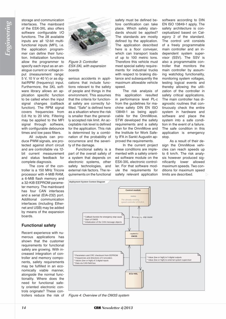
Figure 3: Controller ESX-3XL with expansionboards
deployment System Context Diagram
«system»OM3S
Control module
notes
The already existing speed controller of KUKA.
* Callback function for emergency stop cause* Start of OM3S* Initialization of the CAN message objects
ECU HAL
* Parameters and CRC checksum from EEPROM* Frequencies and directions of 4 encoders* Values (low or high) of 3 digital inputs* Data via CAN field bus
* Value (low or high) to 5 digital outputs* Value (low or high) to external system supervisor
Emergency stop cause
Figure 4: Overview of the OM3S system
14 CAN Newsletter 4/2013
Engi
neer
ing

A STEP AHEADOur new products and services

CANlink WLAN 2103
high data frequency
telemetry data in real timeWireless CAN-data transmission up to 400 meter range: CAN-link WLAN connects CAN-networks and turns smartphoneinto remote controlls.
extended range
Position, elevation orcompass direction: CANview GPS pro-vides cost-effi cient tracing and displays on local CAN-bus interface.
no additionalfi rmware
programmingnecessary
easy and fl exibleconfi guration
CANview GPS
inexpensivegateway-components

CANlogger GPS
power management
analog and digital I/Os
GPSup to two confi gurable CAN-channels
Record CAN-mess-ages and GPS-data using only one device: CANlogger GPS provi-des easy handling and unlimited use.
RM Displays Series 3100
extended ports
easyconfi guration
optional touch screen version
Enlarged displays for optimal representation and simple confi gu-ration: four designs compliment the range of products provided.
illuminated keys
Find out more about our services and products at www.rmcan.com

RMsys Dashboard
The Dashboard desk-top application dis-plays CAN message data in real-time. The surface represen-tation is individually confi gurable.
diagrams
bar graphs
RM MICHAELIDESSOFTWARE & ELECTRONIC CORP.US Subsidiary
711 E. Monument Ave., Suite 310Dayton, Ohio 45402-1490, USAPhone +1 937 558 - 2211Fax +1 937 641 - 8787Toll-Free +1 877 RMCAN-US
RM MICHAELIDESSOFTWARE & ELEKTRONIK GMBHHeadquarters
Donaustr. 1436043 Fulda, GermanyPhone +49 661 9490 - 0Fax +49 661 9490 - 333
DE US
display values
gauges
V-CARD

to meet the requirements of a safety software with performance level PL-c ac-cording to DIN EN ISO 13849-1 the following quali-ty attributes must be fulfilled:
The parameters loaded in non-volatile mem-ory (EEPROM) must be verified with CRC checksums,
The integrity of the main memory (RAM) must be ensured through suitable means,
Program flow control must be monitored with a system supervisor with watch-dog functionality to guarantee the correct program processing.
Among the overall re-quirements for OM3S is the prerequisite that it must be implemented on the PL-d certified safety ESX-3XL controller with integrated hardware diagnostics. The
-nostics is divided into two parts:
Start-up diagnostics that are executed when the controller is switched on and test all of the basic functions, for example the safety relay; these tests cannot be repeated at a later time because they would affect the op-eration of the vehicle,
Periodic tests of memory and CPU for the integrity of content and function, which run in the background, parallel to the application software.
In this project Kuka al-ready uses the controller to
software. The OM3S will also run on this controller with interfaces to:
The vehicle control soft-ware from Kuka, and,
The Hardware Abstrac-tion Layer (HAL) of the controller.
The specifications of this project are processed exclu-sively in database oriented
The first condition is for the load condition. For an empty vehicle the maximum allowed speed is 3 km/h, which is the normal walk-ing speed of a pedestrian (for example, the opera-tor with the remote con-trol unit). For a loaded vehicle the maximum al-lowed speed drops to 1 km/h.
The second condition pertains to vehicles that are outfitted with laser scan-ners that create a protection zone around the vehicle. Laser scanners can bring a vehicle to a stop as soon as they sense an obstacle (e.g. personnel) in the path. There are situations where the laser scanner must be switched off (override con-ditions), for example driving through narrow warehouse
spaces. To guarantee safety under these conditions the maximum allowed speed is reduced to 0,1 km/h.
The maximum allowed speeds are specified based on defined stopping distanc-es during an emergency stop. The OmniMove vehi-cles are intended for many different tasks, meaning a large number of design vari-ants and operational situ-ations. The risk evaluation can therefore also differ sig-nificantly, and the maximum speed must be adjusted ac-cordingly. The maximum speed is set individually for each vehicle type through software parameterization.
The safety oriented software module for speed monitor-
ing has the tasks “Identifica-tion of the currently allowed maximum speed” and “Cal-culation of the actual speed of the vehicle from available signals from three wheels (the fourth wheel provides a redundancy in the speed measurement)”.
If the actual speed is too high or any other er-ror is sensed, an emergen-cy stop must be initiated immediately.
The name of the devel-oped system is OmniMove Speed Surveillance Sys-tem (OM3S). It has the fol-lowing core tasks (functional requirements):
Reliable recognition of the load condition of the vehicle by redundant load sensors,
Reliable recognition of the status of the laser scanner protective field (active or disabled by the override button) by redundant signal paths,
Determination of the cur-rently allowed maximum speed based on load condition and override information,
Reliable reading of the encoder signal from the individual drive wheels of the vehicle through redundant sensors with analogue and/or digital outputs,
Calculation of the ac-tual speed of the vehi-cle from the drive wheel encoders (this can be accomplished by a math-ematical model with the x/y coordinates and the instantaneous rotational velocity of the three drive wheels),
Fault recognition through plausibility check.
Every recognized fault or a speed in excess of the presently allowed maximum speed must result in an emer- gency stop for the vehicle (the safe state). The monitor-ing software must be suitable for all conceivable config-urations (geometry, size, number of driven and auxil-iary wheels, etc.) of the ve-hicle. In order for the system
Frequent and early reviews prevent the development effort of going in the wrong direction or into a dead
design to another person, shortcomings in design will become evident. It will be clear whether the underlying considerations are logical and complete.
Reviews also uncover misunderstandings, differences in interpretation or incompleteness of the requirements. Reviews during the design process should be done to explain the solution, why it was done this way, what alternatives there were, and why they were not chosen. In this way the work of the architect can be reproduced and either confirmed or corrected. The review is an important test that can prevent errors from being propagated.
Figure 6: OmniMove, an extremely agile type of drive for a floor conveyer
19CAN Newsletter 4/2013
Engi
neer
ing
requirements management software. This promotes the atomic capture of individual requirements (individual en-tities) that are referenced by number and can be individ-ually tested. This leads to testable requirements and traceability of the individ-ual requirements through the life cycle of the appli-cation and back to their or-igin or source. The individu-al requirements go through formal reviews by various working groups based on the following criteria, and the results are documented so that they can be incorpo-rated into subsequent ver-sions of the specification: unambiguity, completeness and testability.
The system archi-tecture must be designed before the design of the in-dividual software compo-nents. A second software architect from outside the project must review the ar-chitecture and then it can be refined.
There must be a unit test written for each func-tion that is implemented in a software component. Thus, each software change can be tested completely and preferably automatically.
This ensures that all previous functions still work error-free after the change. After the requirements are put in the specification, they are evaluated for testability.
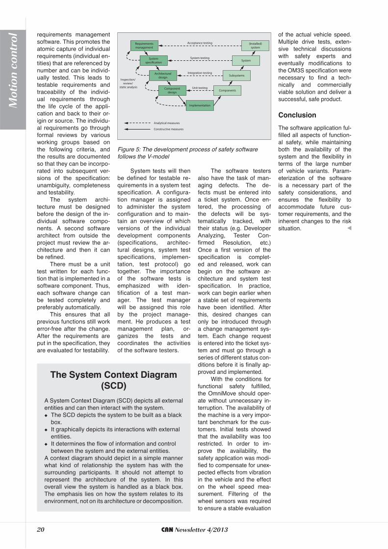
System tests will then be defined for testable re-quirements in a system test specification. A configura-tion manager is assigned to administer the system configuration and to main-tain an overview of which versions of the individual development components (specifications, architec-tural designs, system test specifications, implemen-tation, test protocol) go together. The importance of the software tests is emphasized with iden-tification of a test man-ager. The test manager will be assigned this role by the project manage-ment. He produces a test management plan, or-ganizes the tests and coordinates the activities of the software testers.
The software testers also have the task of man-aging defects. The de-fects must be entered into a ticket system. Once en-tered, the processing of the defects will be sys-tematically tracked, with their status (e.g. Developer Analyzing, Tester Con-firmed Resolution, etc.) Once a first version of the specification is complet-ed and released, work can begin on the software ar-chitecture and system test specification. In practice, work can begin earlier when a stable set of requirements have been identified. After this, desired changes can only be introduced through a change management sys-tem. Each change request is entered into the ticket sys-tem and must go through a series of different status con-ditions before it is finally ap-proved and implemented.
With the conditions for functional safety fulfilled, the OmniMove should oper-ate without unnecessary in-terruption. The availability of the machine is a very impor-tant benchmark for the cus-tomers. Initial tests showed that the availability was too restricted. In order to im-prove the availability, the safety application was modi-fied to compensate for unex-pected effects from vibration in the vehicle and the effect on the wheel speed mea-surement. Filtering of the wheel sensors was required to ensure a stable evaluation
Requirementsmanagement
Systemspecification
Architecturaldesign
Componentdesign
(Installed)system
System
Acceptance testing
System testing
Integration testing
Unit testing
Analytical measures
Constructive measures
Subsystems
Components
Implementation
Inspection/ review/
static analysis
Figure 5: The development process of safety software follows the V-model
of the actual vehicle speed. Multiple drive tests, exten-sive technical discussions with safety experts and eventually modifications to the OM3S specification were necessary to find a tech-nically and commercially viable solution and deliver a successful, safe product.
The software application ful-filled all aspects of function-al safety, while maintaining both the availability of the system and the flexibility in terms of the large number of vehicle variants. Param-eterization of the software is a necessary part of the safety considerations, and ensures the flexibility to accommodate future cus-tomer requirements, and the inherent changes to the risk situation.
A System Context Diagram (SCD) depicts all external entities and can then interact with the system.
The SCD depicts the system to be built as a black box.
It graphically depicts its interactions with external entities.
It determines the flow of information and control between the system and the external entities.
A context diagram should depict in a simple manner what kind of relationship the system has with the surrounding participants. It should not attempt to represent the architecture of the system. In this overall view the system is handled as a black box. The emphasis lies on how the system relates to its environment, not on its architecture or decomposition.
(SCD)
20 CAN Newsletter 4/2013
Mot
ion
cont
rol