Embed Size (px)
Citation preview

GILL SAND PIT FORMSF440 & F460 SERIES
FORMS WITH CATCHERS ON 2 SIDES
INSTRUCTIONS
2018 by Gill Athletics. All rights reserved. INSTF440 - Page 1
www.gillathletics.com
SAND PIT FORMS
Copyright
800-637-3090

WARNING: Cancer and Reproductive Harm – For more information go to www.p65warnings.ca.gov
F

•
Typical Self-drillingScrew Connection
Patio bricks or concrete blocks for form leveling •Mortar for leveling bricks
Typical Bolted Connection
•
NOTE: This is NOT meant to be an exhaustive list of tools for the installation of this product.
Recommended Tool List:
7/16" wrenches and driver•5/16" driver•Level(s)•Rubber mallet•Drill/bit driver•Tape measure•Clamps•String•Spray paint•
Additional Materials:
Duct tape
When assembling the sand pit forms there will be two types of connections; bolted connections and self-drilling screw connections.
Bolted connections consist of: one (1) 1/4"-20 x 1" long bolt, two (2) 1/4" flat washers, and one (1) 1/4"-20 hex nut.•Self-drilling screw connections consist of: one (1) self drilling screw•
Examples of each connection are shown below.
2018 by Gill Athletics. All rights reserved. INSTF4xx - Page 3
www.gillathletics.com
SAND PIT FORMSINSTRUCTIONS
Copyright
800-637-3090
Bolt
Washer WasherNut
Items to be Connected
Self-drilling screw
Items to be Connected

Hole Spacing Length12" 24"12" 35.75"12" 60"12" 72"
14.5" 28.75"14.5" 58"
PICTURE
DURING INSTALLATION YOU MAY USE:
DESCRIPTION VARIATIONS
36" Long58" Long72" Long
Base Form
Ledge Angle
42" LongEndplate
2x4 Form Brace
Corner Angle
Sand Catcher Brace
Sand Catcher Grate and Rubber
18.5" Long116" Long
36" Long
-
-
42" Long
36" Long
2018 by Gill Athletics. All rights reserved. INSTF440 - Page 4
www.gillathletics.com
SAND PIT FORMSINSTRUCTIONS
Copyright
800-637-3090

16"
Table 1 - Minimum Pit Excavation DimensionsModel Length Width Depth
F44023 or F46023 26'-2"16'-9" 18"F44026 or F46026 29'-2"
F44029 or F46029 32'-2"
IT IS IMPORTANT TO READ ALL INSTRUCTIONS BEFORE BEGINNING INSTALLATION
NOTICE: All installations should be conducted by experienced contractors and in accordance with all applicable codes, laws, and regulations. Suggested instructions herein are illustrative only and should be adapted to suit local requirements. Gill Athletics is not responsible for the manner in which this product is installed.
The installer/contractor must locate the sand pit form in •accordance with plans and specifications. It is recommended that an area be prepared to accept the dimensions of the form. The recommended minimum dimensions for the excavation are given for each model in Table 1.The installed form must be level and square and •correctly positioned with respect to the track layout.The inside wall of the assembled forms will define the •landing area of the sand pit. Locate where the joints and corners of the forms will be positioned and mark the subgrade with spray paint at these positions. See attached appendices for the dimension of the specific model being installed.The sand pit forms should be installed on a level •surface. It is up to the installer/contractor on how to achieve this. Options include but are not limited to:
Poured concrete pad•Graded and compacted subgrade•Shims•Brick/block in mortar•
If set on crushed rock/gravel/sand the same final height •must be obtained and the form must be level and square.Track surface will be applied to the top of the sand pit •forms. Refer to the architectural plans for surface elevation, finish, and thickness. It is the responsibility of the installer/ contractor to install the forms at the correct depth as to maintain the correct surface elevation.
2018 by Gill Athletics. All rights reserved. INSTF440 - Page 5
www.gillathletics.com
SAND PIT FORMSINSTRUCTIONS
Copyright
800-637-3090
Level
Track SurfaceTop of Forms
Surface
Bottom of Forms/Established
Bottom of Excavation

F440 or F460 Series
views below the endplates have been hidden).
Before getting started, look in the appendices for the overview sheet on the specific model being installed. Familiarize yourself with where the joints are and how the forms will be positioned with respect to each other. In the following pages, the forms will beassembled into end wall and side wall sections. These separate wall sections will then be combined with endplates (Note: in the
An example is shown below:
2018 by Gill Athletics. All rights reserved. INSTF440 - Page 6
www.gillathletics.com
SAND PIT FORMSINSTRUCTIONS
Copyright
800-637-3090
Single End Walls
Double Side Walls
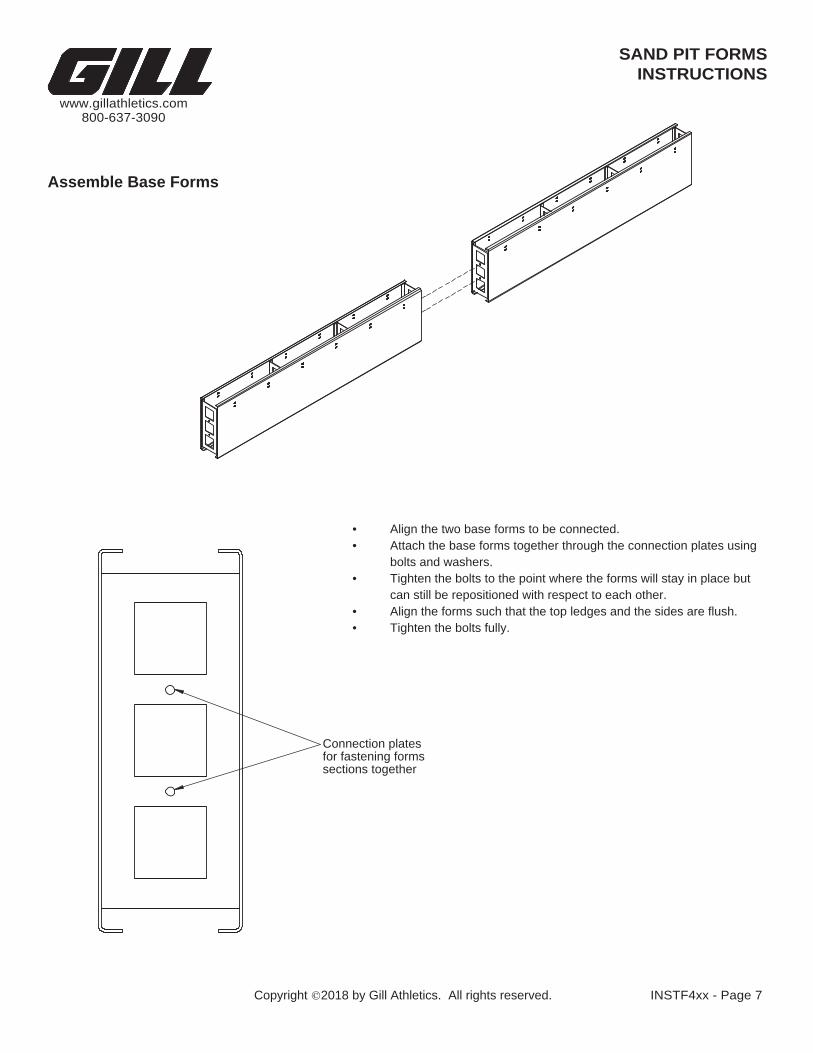
Assemble Base Forms
Align the two base forms to be connected.•Attach the base forms together through the connection plates using •bolts and washers.Tighten the bolts to the point where the forms will stay in place but •can still be repositioned with respect to each other.Align the forms such that the top ledges and the sides are flush.•Tighten the bolts fully.•
2018 by Gill Athletics. All rights reserved. INSTF4xx - Page 7
www.gillathletics.com
SAND PIT FORMSINSTRUCTIONS
Copyright
800-637-3090
Connection plates for fastening forms sections together

LOWER SLOTCover ledge angle installed on
INSIDE on the WALL OF THE SAND PIT
Sand catcher ledge angles installed onUPPER SLOT on the INSIDE WALLS OFTHE SAND CATCHER
1"REF
1 1516 "
REF
with duct tape on the inside of the base form(pictured) before
Attach Ledge Angles
Sand Storage Area
•
Sand Pit Landing Area
concrete is poured.
Refer to the overview sheet for the specific model being •installed.The overview sheet will specify the size of angles needed and •their placement for each specific model.The angles will be staggered across form to form joints.•The angles on the inside of the sand pit will be installed in the •lower slots. The angles for the sand catcher will be installed in the upper slotsAny unused slots on the base forms will need to be covered
Duct Tape
2018 by Gill Athletics. All rights reserved. INSTF44x - Page 8
www.gillathletics.com
SAND PIT FORMSINSTRUCTIONS
Copyright
800-637-3090
Lower Slot
Upper Slot

2018 by Gill Athletics. All rights reserved. INSTF4xx - Page 9
www.gillathletics.com
SAND PIT FORMSINSTRUCTIONS
Copyright
800-637-3090
Attach Endplates
End Plates
Tighten bolts fully.
Sand Pit
•
Align the end plate with the end of the form(s) to •be connected.Attach the base forms to the end plate using •bolts and washers through the connection plate and the holes in the end plateTighten the bolts to the point where the form and •end plate can still be repositioned with respect to each other.Align the end plate such that the top is flush with •the top of the forms and the edge is flush with the side of the forms.
End Plates
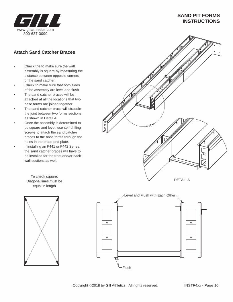
Attach Sand Catcher Braces
equal in length
the sand catcher braces will have to be installed for the front and/or back wall sections as well.
Check the to make sure the wall •assembly is square by measuring the distance between opposite corners of the sand catcher.Check to make sure that both sides •of the assembly are level and flush.The sand catcher braces will be •attached at all the locations that two base forms are joined together.The sand catcher brace will straddle •the joint between two forms sections as shown in Detail A.Once the assembly is determined to •be square and level, use self-drilling screws to attach the sand catcher braces to the base forms through the holes in the brace end plate.If installing an F441 or F442 Series, •
To check square:Diagonal lines must be
2018 by Gill Athletics. All rights reserved. INSTF4xx - Page 10
www.gillathletics.com
SAND PIT FORMSINSTRUCTIONS
Copyright
800-637-3090
Level and Flush with Each Other
Flush
A
DETAIL A
SAND PIT FORMSINSTRUCTIONS
2018 by Gill Athletics. All rights reserved. INSTF4xx - Page 11
www.gillathletics.com
Copyright
800-637-3090
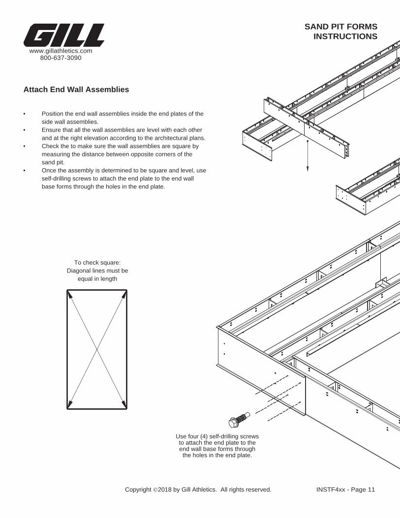
To check square:
to attach the end plate to the
base forms through the holes in the end plate.
Attach End Wall Assemblies
Diagonal lines must be
the holes in the end plate.
Use four (4) self-drilling screws
equal in length
self-drilling screws to attach the end plate to the end wall
end wall base forms through
Position the end wall assemblies inside the end plates of the •side wall assemblies.Ensure that all the wall assemblies are level with each other •and at the right elevation according to the architectural plans.Check the to make sure the wall assemblies are square by •measuring the distance between opposite corners of the sand pit.Once the assembly is determined to be square and level, use •

interfere with the ledge angles.
Attach Corner Angles
base forms through the holes in the corner angle. The corner angles should be installed such that they do not • Once the assembly is determined to be square and level, use self-drilling screws to attach the angles to the
Ensure that all the wall assemblies are level with each other and at the right elevation according to the •architectural plans.Check the to make sure the wall assemblies are square by measuring the distance between opposite corners •of the sand pit.The corner angles will be attached in the interior corners of the sand pit.•
Use four (4) self-drilling screws to attach the corner angle to the base forms through the holes in the corner angle.
INSTRUCTIONS
2018 by Gill Athletics. All rights reserved. INSTF440 - Page 12
www.gillathletics.com
SAND PIT FORMS
Copyright
800-637-3090
CornerAngle

Install Wooden Form Bracing
Wooden bracing is provided to help prevent shifting and movement of the forms during the concrete pour, curing, and •back-fill operationsPlace the bracing 2x4 at the bottom of the forms and on top of the ledge angles at the joints in the base forms. Also install •2x4 bracing on top of the angles in the sand catcher.
2018 by Gill Athletics. All rights reserved. INSTF4xx - Page 13
www.gillathletics.com
SAND PIT FORMSINSTRUCTIONS
Copyright
800-637-3090
Install top, bottom, and sand catcher
top brace
2x4 Wood2x4 Wood
18.5" Sand Catcher Brace9'-8" Main Brace
18.5" Sand Catcher BraceAluminum(Previously Installed)

Sand Storage Area Sand Pit Landing Area
BEFORE POURING CONCRETE CHECK THE FOLLOWING ITEMS:
Check that all bolts are tight.•Check that the sand pit forms are square.•Check that the sand pit forms are level.•Check that the sand pit forms are placed according to the architectural plans •and specifications.Check that all un-used slots have duct tape covering them inside the forms.•Check the depth of the ledge angles:•
Sand pit ledge angles should be installed in the LOWER slots on the base •form and be 1-15/16" below top of the base forms.Sand catcher ledge angles should be installed in the UPPER slots on the •base form and be 1" below the top of the base forms.
2018 by Gill Athletics. All rights reserved. INSTF4xx - Page 14
www.gillathletics.com
SAND PIT FORMSINSTRUCTIONS
Copyright
800-637-3090
THE SAND CATCHERINSIDE WALLS OF
Sand catcher ledgeangles installed on
UPPER SLOT on theCover ledge angle installed onLOWER SLOT on the INSIDEWALL OF THE SAND PIT
"16 1" 1 15
18 12 "

3" - 4" of concretein bottom of sand catcher 3" - 4" of concrete
in bottom of sand catcher
Pour concrete into the forms through the opening in the top
As specified by architectSlope and drain
9'-8" 18 "21 18 1
2 "
As specified by architectOptional sand catcher drainage
PVC Pipe
Gravel Base
SAND
Pour Concrete
Before and during the concrete pour, check the pit dimensions to make sure no shifting has occurred.•
Pour concrete into the forms through the opening at the top.•Pour concrete into the bottom of the sand catcher as to fully cover the permanent sand catcher braces, about 3" - 4".•Smooth the concrete off at the top of the forms and bottom of sand catcher then cover with plastic or apply a wax film •over all exposed concrete to minimize water loss.
Allow the concrete to set hard before proceeding further.•
Keep the wooden bracing in place while concrete is curing and during back-fill operations.•Using the specified or appropriate fill material, back-fill and compact around the outside of the sand pit forms.•It is recommended that at this time the specified fill material inside the pit, i.e. crushed stone, filter fabric, pit sand, etc.•also be installed. This will help further stabilize the sand pit walls against movement.
2018 by Gill Athletics. All rights reserved. INSTF44x - Page 15
www.gillathletics.com
SAND PIT FORMSINSTRUCTIONS
Copyright
800-637-3090
3" - 4" of concretein bottom of sand catcher 3" - 4" of concrete
in bottom of sand catcher

Covers Go Here
For F440 & F460 Models:
Track Surface
2018 by Gill Athletics. All rights reserved. INSTF440 - Page 16
www.gillathletics.com
SAND PIT FORMSINSTRUCTIONS
Copyright
800-637-3090
F440
Install Sand Catcher Covers
included zip ties.- The sand catcher covers measure 18" x 36".
- The included sand catcher covers come as two pieces: a metal grate and a rubber mat.- The rubber mat can be attached the to metal grate with the
- The sand catcher covers measure 18" x 36".
F460- The included sand catcher covers are recessed to receive track surface.- Poured track surface OR roll out track surface can be used.- The track surface material is not included.
Sand Catcher Cover Assembly
Recessed Tray
Metal Grate
Rubber Mat

2018 by Gill Athletics. All rights reserved.
www.gillathletics.com
SAND PIT FORMSINSTRUCTIONS
Copyright
800-637-3090
APPENDICESThese overview sheets are attached to help clarify the location and size of base
There is an overview sheet for each specific model.
forms and ledge angles.
F44023 & F46023 - Sand Pit Form with Side Sand Catchers - 23' LongF44026 & F46026 - Sand Pit Form with Side Sand Catchers - 26' LongF44029 & F46029 - Sand Pit Form with Side Sand Catchers - 29' Long

Angles are called out with circles.
Other components and details may be omitted.
Base forms are called out with diamonds.
This drawing represents how the base form sections and angles should be positioned.
ITEM NO.
PART NUMBER DESCRIPTION QTY.
1 F44089 72" SAND PIT BASE FORM 16
2 F44088 58" SAND PIT BASE FORM 4
3 F44086 72" SLOTTED LEDGE ANGLE 18
4 F44081 24" SLOTTED LEDGE ANGLE 4
5 F44084 58" SLOTTED LEDGE ANGLE 2
6 F44082 28.75" SLOTTED LEDGE ANGLE 4
7 F44083 35.75" SLOTTED LEDGE ANGLE 8
Page 1 of 1
www.gillathletics.com
F44023 - Overview10/31/2011
800-637-3090
All rights reserved.
F44023 & F46023 - SAND PIT FORM with SIDE SAND TRAPS
Copyright 2011 by Gill Athletics.
OVERVIEW
3
64
6
1
4
1
5
2
1
4
5
3
67
3
4
1
3
6
3
3
3
1
3
7
3
1
3
3 3
2
7
1
1
7
24'
-2"
23'
-0"
9'-8"
14'-9"
9 9
1
4
6
2
3
1
1
4
5
9 6 9
4
5
4
4
1
4
8
4
4
4
7
4
4
1
44
7
2
8
3
1
1
1
4
27'
-2"
26'
-0"
9'-8"
14'-9"
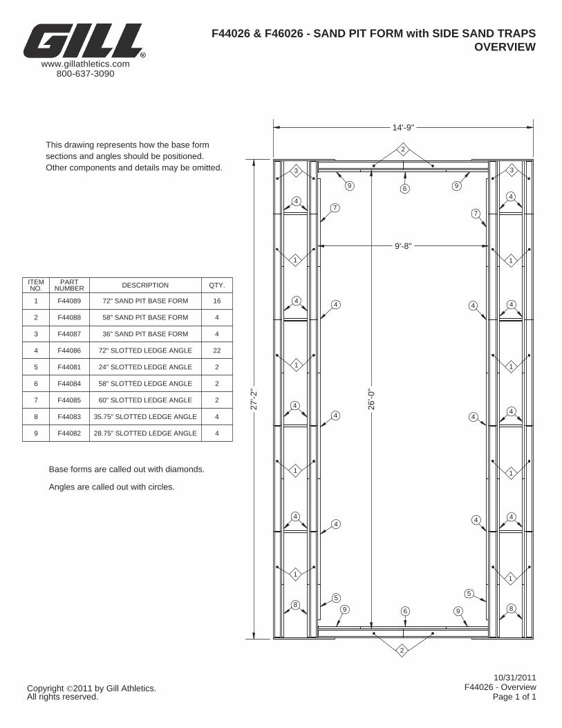
Angles are called out with circles.
Other components and details may be omitted.
Base forms are called out with diamonds.
This drawing represents how the base form sections and angles should be positioned.
ITEM NO.
PART NUMBER DESCRIPTION QTY.
1 F44089 72" SAND PIT BASE FORM 16
2 F44088 58" SAND PIT BASE FORM 4
3 F44087 36" SAND PIT BASE FORM 4
4 F44086 72" SLOTTED LEDGE ANGLE 22
5 F44081 24" SLOTTED LEDGE ANGLE 2
6 F44084 58" SLOTTED LEDGE ANGLE 2
7 F44085 60" SLOTTED LEDGE ANGLE 2
8 F44083 35.75" SLOTTED LEDGE ANGLE 4
9 F44082 28.75" SLOTTED LEDGE ANGLE 4
F44026 & F46026 - SAND PIT FORM with SIDE SAND TRAPS
www.gillathletics.com
F44026 - Overview10/31/2011
800-637-3090
All rights reserved. Page 1 of 1Copyright 2011 by Gill Athletics.
OVERVIEW

Angles are called out with circles.
sections and angles should be positioned.
Base forms are called out with diamonds.
This drawing represents how the base form
Other components and details may be omitted.
ITEM NO.
PART NUMBER DESCRIPTION QTY.
1 F44089 72" SAND PIT BASE FORM 20
2 F44088 58" SAND PIT BASE FORM 4
3 F44086 72" SLOTTED LEDGE ANGLE 24
4 F44081 24" SLOTTED LEDGE ANGLE 4
5 F44084 58" SLOTTED LEDGE ANGLE 2
6 F44082 28.75" SLOTTED LEDGE ANGLE 4
7 F44083 35.75" SLOTTED LEDGE ANGLE 8
Page 1 of 1
www.gillathletics.com
10/31/2011F44029 - Overview
800-637-3090
All rights reserved.
F44029 & F46029 - SAND PIT FORM with SIDE SAND TRAPS
Copyright 2011 by Gill Athletics.
OVERVIEW
64
6
4
1
75
2
1
1
1
3
3
4
6 5 6
3
4
3
3
1
3
7
3
3
3
33
3
3
1
33
3
2
7
1
1
1
1
7
30'
-2"
29'
-0"
9'-8"
14'-9"


![Telecommunication Products - Trendtek jointing pits.pdf · [01] UG2006 - P6 Pit UG2007 - P7 Pit UG2008 - P8 Pit UG2900 - P9 Pit UG2001 - P1 Pit UG2002 - P2 Pit UG2003 - P3 Pit UG2004](https://img.pdfslide.us/doc/110x75/5a7969077f8b9ab9308d3433/telecommunication-products-jointing-pitspdf01-ug2006-p6-pit-ug2007-p7-pit.jpg)