Embed Size (px)
Citation preview

Gigabit Ethernet PoE+ Unmanaged Switch
User Manual
Version 1.0 – August 2013
POEGE8TV2V2
POEGE8TV2 User Manual
Alloy Computer Products Pty Ltd Copyright ©2013
Contents
1. Introduction .............................................................. 6 2. Checklist ................................................................... 6 3. Installation ................................................................ 7
3.1 Installation Method ........................................................................ 7 3.2 Desktop or Shelf Installation ........................................................... 7 3.3 Rack Installation ............................................................................. 7
4. Powering on the Switch .................................................. 9 5. LED Description ........................................................... 9 6. Network Connection ................................................... 10 7. Technical Specifications ................................................ 11 Appendix A. RJ-45 Connections .......................................... 12

POEGE8TV2 User Manual
Alloy Computer Products Pty Ltd Copyright ©2013
Compliances and Safety Statements
Federal Communications Commission (FCC) Statement
This equipment has been tested and found to comply with the limits for a Class A digital device, pursuant to part 15 of the FCC Rules. These limits are designed to provide reasonable protection against harmful interference in a residential installation. This equipment generates, uses and can radiate radio frequency energy and, if not installed and used in accordance with the instructions, may cause harmful interference to radio communications. However, there is no guarantee that interference will not occur in a particular installation. If this equipment does cause harmful interference to radio or television reception, which can be determined by turning the equipment off and on, the user is encouraged to try to correct the interference by one or more of the following measures:
Reorient or relocate the receiving antenna
Increase the separation between the equipment and receiver
Connect the equipment into an outlet on a circuit different from that to which the receiver is connected
Consult the dealer or an experienced radio/TV technician for help This device complies with Part 15 of the FCC Rules. Operation is subject to the following two conditions: (1) This device may not cause harmful interference, and (2) this device must accept any interference received, including interference that may cause undesired operation. FCC Caution: Any changes or modifications not expressly approved by the party responsible for compliance could void the user's authority to operate this equipment. European Community (CE) Electromagnetic Compatibility Directive This information technology equipment complies with the requirements of the Council Directive 89/336/EEC on the Approximation of the laws of the Member States relating to Electromagnetic Compatibility and 73/23/EEC for electrical equipment used within certain voltage limits and the Amendment Directive 93/68/EEC. For the evaluation of the compliance with these Directives, the following standards were applied: RFI Emission: - Limit according to EN 55022:2010 AS/NZS CISPR 22:2009, Class A
- Limit for harmonic current emission according to EN 61000-3- 2:2006+A1:2009+A2:2009 - Limitation of voltage fluctuation and flicker in low-voltage supply system according to EN 61000-3-3:2008
Immunity: - Product family standard according to EN 55024:2010 - Electrostatic Discharge according to IEC 61000-4-2:2008 - Radio-frequency electromagnetic field according to IEC 61000-4- 3:2006+A1:2007+A2:2010 - Electrical fast trsnsient/burst according to IEC 61000-4-4:2010 - Surge immunity test according to IEC 61000-4-5:2005 - Immunity to conducted disturbances, Induced by radio-frequency fields:IEC 61000-4-6:2008 - Power frequency magnetic field immunity test according to IEC 61000-4-8:2009 - Voltage dips, short interruptions and voltage variations immunity test

POEGE8TV2 User Manual
Alloy Computer Products Pty Ltd Copyright ©2013
according to IEC 61000-4-11:2004
LVD: - EN60950-1:2006+A11:2009+A1:2010EMC: Australian C-Tick Compliance. This equipment is compliant with the required Australian C-Tick standards PLEASE READ THE FOLLOWING SAFETY INFORMATION CAREFULLY BEFORE INSTALLING THE SWITCH: WARNING: Installation and removal of the unit must be carried out by qualified personnel only.
This guide is intended for use by network administrators who are responsible for setting up and installing network equipment; consequently it assumes a basic working knowledge of LANs (Local Area Networks).
The unit must be connected to an earthed (grounded) outlet to comply with international safety standards.
Do not connect unit to an A.C outlet (power supply) without an earth (ground) connection.
The appliance coupler (the connector to the unit and not the wall plug) must have a configuration for mating with an EN 60320/IEC 320 appliance inlet.
The socket outlet must be near to the unit and easily accessible. You can only remove power from the unit by disconnecting the power cord from the outlet.
This unit operates under SELV (Safety Extra Low Voltage) conditions according to IEC 60950. The conditions are only maintained if the equipment to which it is connected also operates under SELV conditions.

POEGE8TV2 User Manual
Alloy Computer Products Pty Ltd Copyright ©2013
SAFETY PRECAUTIONS Read the following information carefully before operating the device. Please follow the following precaution items to protect the device from risks and damage caused by fire and electric power:
Use the power adapter that is included with the device package.
Pay attention to the power load of the outlet or prolonged lines. An overburdened power outlet or damaged cords and plugs may cause electric shock or fire. Check the power cords regularly, if you find any damage, replace it at once.
Proper space for heat dissipation is necessary to avoid any damage caused by device overheating. The ventilation holes on the device are designed for heat dissipation to ensure that the device works normally. Do not cover these ventilation holes.
Do not put this device close to a place where a heat source exits or high temperature occurs. Avoid placing the device in direct sunshine.
Do not put this device close to a place which is damp or wet. Do not spill any fluid on this device.
Please follow the instructions in the user manual/quick install guide carefully to connect the device to your PC or other electronic product. Any invalid connection may cause a power or fire risk.
Do not place this device on an unstable surface or support.

POEGE8TV2 User Manual
Alloy Computer Products Pty Ltd Copyright ©2013
1. Introduction
The POEGE8TV2 is an unmanaged low cost Gigabit Ethernet Power Over Ethernet switch. The switch consists of 8x 10/100/1000Mbps PoE ports. All ports are auto sensing, auto MDI/X ports allowing easy connectivity to your existing switching infrastructure and your PD PoE devices, such as IP Phones, Wireless Access Points and IP Video Cameras. All ports support up to 30W of power, with the switch supporting 18.75W per port at full load. The POEGE8TV2 supports up to 150W in total. The POEGE8TV2 is the ideal solution for adding low cost PoE capability to your newly deployed IP PBX and IP Phone infrastructure.
Features
- Supports PoE power up to 30W for each PoE port - Supports PoE power up to 150W for all PoE ports - Supports PoE IEEE802.3at/af compliant PDs - Supports IEEE802.3x flow control for Full-duplex Mode and backpressure for Half-
duplex Mode - 2K MAC address with auto-learning and auto-aging - LED indicators for monitoring power, link, activity and speed
2. Checklist
Before you start installing your equipment, verify that the package contains the following:
The POEGE8TV2 – Gigabit Ethernet POE+ Switch
Rack Mount kit with appropriate mounting screws
Power Cable
This Users Manual CD-ROM
Please notify your supplier immediately if any of the aforementioned items are missing or damaged.
POEGE8TV2 User Manual
Alloy Computer Products Pty Ltd Copyright ©2013
3. Installation
3.1 Installation Method The site where you install the switch may greatly affect its performance. When installing, please take the following into consideration.
- Install the switch in a cool, dry place. See technical specifications for the acceptable temperature and humidity operating ranges.
- Install the switch on a secure, level surface that can support its weight, at least 5Kg. - Before connecting the Power Cord please ensure the appropriate voltage switch is
set, this switch can be found at the back of the POEGE8TV2. - Leave at least 10cm of space at the front and rear of the switch to ensure adequate
ventilation.
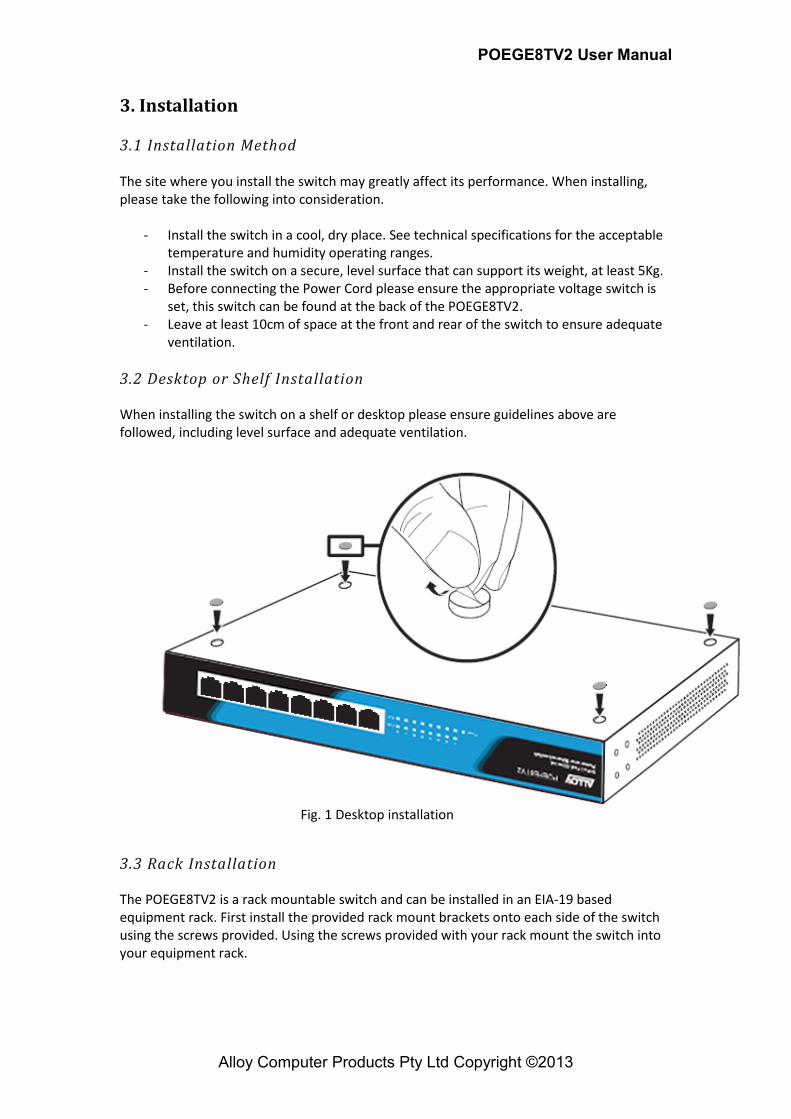
3.2 Desktop or Shelf Installation When installing the switch on a shelf or desktop please ensure guidelines above are followed, including level surface and adequate ventilation.
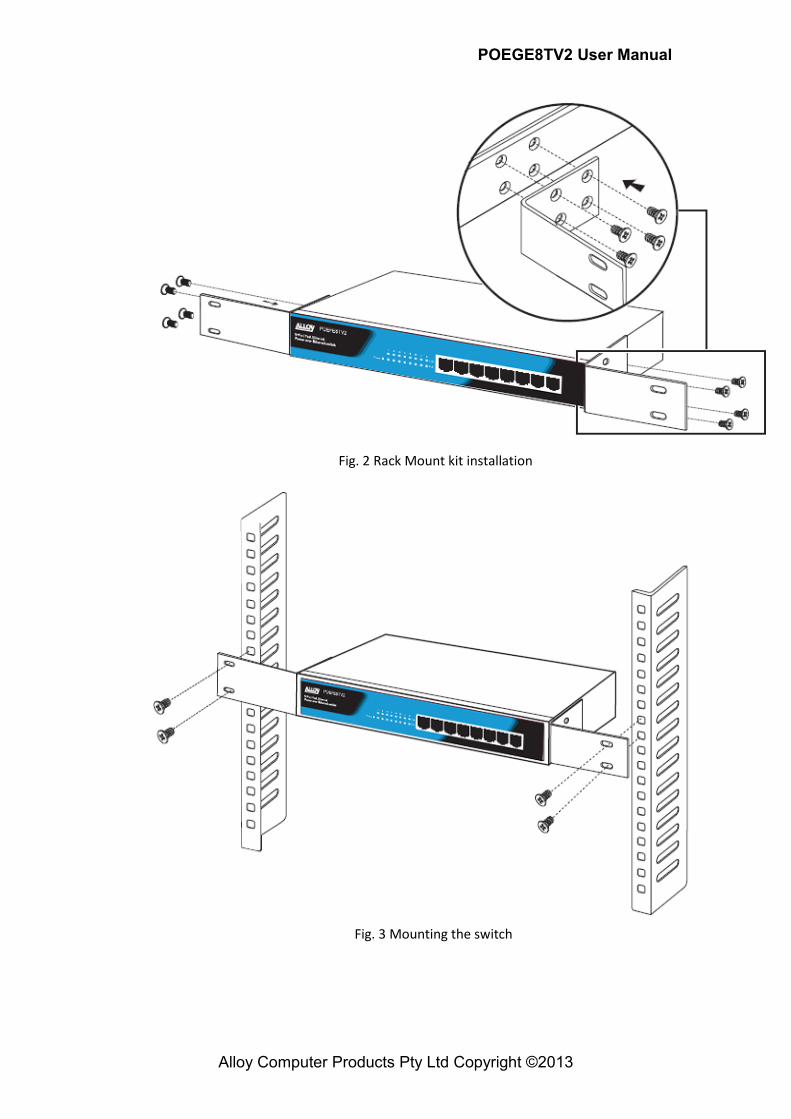
3.3 Rack Installation The POEGE8TV2 is a rack mountable switch and can be installed in an EIA-19 based equipment rack. First install the provided rack mount brackets onto each side of the switch using the screws provided. Using the screws provided with your rack mount the switch into your equipment rack.
Fig. 1 Desktop installation
POEGE8TV2 User Manual
Alloy Computer Products Pty Ltd Copyright ©2013
Fig. 2 Rack Mount kit installation
Fig. 3 Mounting the switch
POEGE8TV2 User Manual
Alloy Computer Products Pty Ltd Copyright ©2013
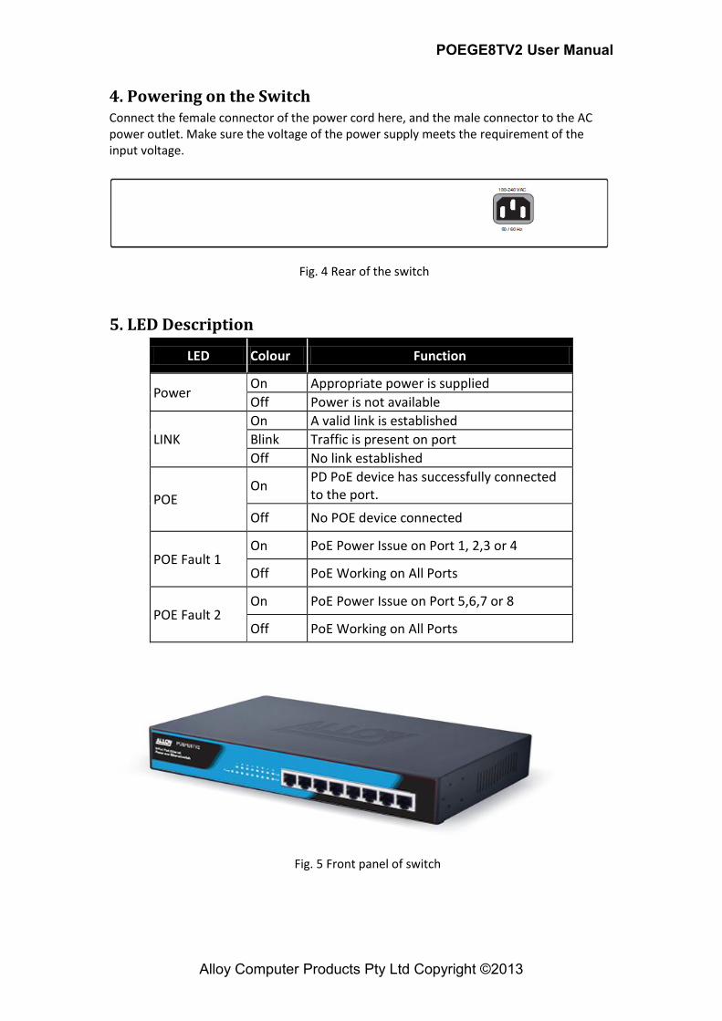
4. Powering on the Switch Connect the female connector of the power cord here, and the male connector to the AC power outlet. Make sure the voltage of the power supply meets the requirement of the input voltage.
5. LED Description
LED Colour Function
Power On Appropriate power is supplied
Off Power is not available
LINK
On A valid link is established
Blink Traffic is present on port
Off No link established
POE On
PD PoE device has successfully connected to the port.
Off No POE device connected
POE Fault 1 On PoE Power Issue on Port 1, 2,3 or 4
Off PoE Working on All Ports
POE Fault 2 On PoE Power Issue on Port 5,6,7 or 8
Off PoE Working on All Ports
Fig. 4 Rear of the switch
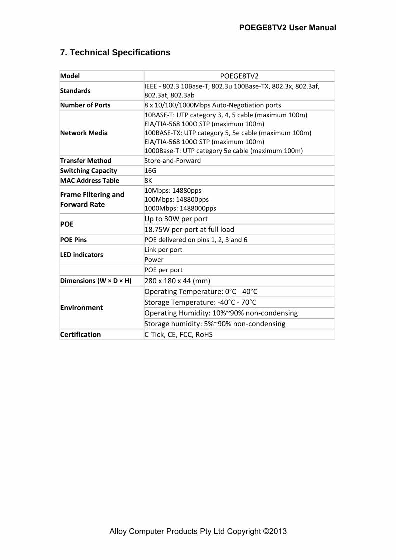
Fig. 5 Front panel of switch

POEGE8TV2 User Manual
Alloy Computer Products Pty Ltd Copyright ©2013
6. Network Connection This switch is designed to be connected to 10, 100 or 1000Mbps network cards in PCs and Servers, as well as to other switches and hubs.
Cabling Guidelines The RJ-45 ports on the switch support automatic MDI/MDI-X pinout configuration, so you can use standard straight-through twisted-pair cables to connect to any other network device (PCs, servers, switches, routers, or hubs). Each device requires an unshielded twisted-pair (UTP) cable with RJ-45 connectors at both ends. Use Category 5 or better for 100BASE-TX connections, and Category 3 or better for 10BASE-T connections.
Connecting To Pcs, Servers, Hubs And Switches 1. Attach one end of a twisted-pair cable segment to the device’s RJ-45 connector.
2. Attach the other end of the cable segment to an available port on the switch.
Make sure each twisted pair cable does not exceed 100 meters (328 ft) in length.
3. As each connection is made, the relevant port LED (on the switch) corresponding to
each port will turn on green to indicate that the connection is valid.
POEGE8TV2 User Manual
Alloy Computer Products Pty Ltd Copyright ©2013
7. Technical Specifications
Model POEGE8TV2
Standards IEEE - 802.3 10Base-T, 802.3u 100Base-TX, 802.3x, 802.3af, 802.3at, 802.3ab
Number of Ports 8 x 10/100/1000Mbps Auto-Negotiation ports
Network Media
10BASE-T: UTP category 3, 4, 5 cable (maximum 100m) EIA/TIA-568 100Ω STP (maximum 100m) 100BASE-TX: UTP category 5, 5e cable (maximum 100m) EIA/TIA-568 100Ω STP (maximum 100m) 1000Base-T: UTP category 5e cable (maximum 100m)
Transfer Method Store-and-Forward
Switching Capacity 16G
MAC Address Table 8K
Frame Filtering and Forward Rate
10Mbps: 14880pps 100Mbps: 148800pps 1000Mbps: 1488000pps
POE Up to 30W per port
18.75W per port at full load
POE Pins POE delivered on pins 1, 2, 3 and 6
LED indicators Link per port
Power
POE per port
Dimensions (W × D × H) 280 x 180 x 44 (mm)
Environment
Operating Temperature: 0°C - 40°C
Storage Temperature: -40°C - 70°C
Operating Humidity: 10%~90% non-condensing
Storage humidity: 5%~90% non-condensing
Certification C-Tick, CE, FCC, RoHS

POEGE8TV2 User Manual
Alloy Computer Products Pty Ltd Copyright ©2013
Appendix A. Troubleshooting
Diagnosing Switch Indicators The Power Led Is Off
Make sure the AC power cord is connected to the switch and power source properly.
Make sure the power source is ON. The Link/Act Led Is Off When A Device Is Connected To The Corresponding Port
Make sure that the cable connectors are firmly plugged into the switch and the device.
Make sure the connected device is turned on and working properly.
The cable must be less than 100 meters long (328 feet).
Check the port on the attached device and cable connections for possible
defects. Replace the defective cable if necessary. Power And Cooling Problems If the power indicator does not turn on when the power cord is plugged in, you may have a problem with the power outlet, power cord, or internal power supply. However, if the unit powers off after running for a while, check for loose power connections, power losses or surges at the power outlet. If you still cannot isolate the problem, the internal power supply may be defective.

POEGE8TV2 User Manual
Alloy Computer Products Pty Ltd Copyright ©2013
Appendix B. RJ-45 Connections
RJ-45 Connector pin out
Pin no. MDI-I signal MDI-X signal
1 TX+ RX+
2 TX- RX-
3 RX+ TX+
4 not used not used
5 not used not used
6 RX- TX-
7 not used not used
8 not used not used
Below is a diagram of a typical straight through and cross-over cable connection:
Fig. 4 RJ-45 Connectors, switch and cable views
Fig. 5 Straight Through Cable connection
Fig. 6 Cross-Over Cable connection