Embed Size (px)
Citation preview
Giant Magellan Telescope - Overview
Matt Johns, Patrick McCarthy, Keith Raybould, Antonin Bouchez, Arash Farahani, Jose Filgueira, George Jacoby, Steve Shectman, Michael Sheehan
GMTO Corporation, 251 South Lake Ave., Suite 300, Pasadena, CA 91101, USA
ABSTRACT
The Giant Magellan Telescope (GMT) is a 25-meter optical/infrared extremely large telescope that is being built by an international consortium of universities and research institutions. It will be located at the Las Campanas Observatory, Chile. The GMT primary mirror consists of seven 8.4-m borosilicate honeycomb mirror segments made at the Steward Observatory Mirror Lab (SOML). Six identical off-axis segments and one on-axis segment are arranged on a single nearly-paraboloidal parent surface having an overall focal ratio of f/0.7. The fabrication, testing and verification procedures required to produce the closely-matched off-axis mirror segments were developed during the production of the first mirror. Production of the second and third off-axis segments is underway. GMT incorporates a seven-segment Gregorian adaptive secondary to implement three modes of adaptive-optics operation: natural-guide star AO, laser-tomography AO, and ground-layer AO. A wide-field corrector/ADC is available for use in seeing-limited mode over a 20-arcmin diameter field of view. Up to seven instruments can be mounted simultaneously on the telescope in a large Gregorian Instrument Rotator. Conceptual design studies were completed for six AO and seeing-limited instruments, plus a multi-object fiber feed, and a roadmap for phased deployment of the GMT instrument suite is being developed. The partner institutions have made firm commitments for approximately 45% of the funds required to build the telescope. Project Office efforts are currently focused on advancing the telescope and enclosure design in preparation for subsystem- and system-level preliminary design reviews which are scheduled to be completed in the first half of 2013. Keywords: GMT, GMTO Corporation, extremely large telescope, overview, Giant Magellan Telescope
1. INTRODUCTION
1.1. GMT Organization The Giant Magellan Telescope (GMT) is a 25-meter optical/infrared extremely large telescope that is being built by an international consortium of universities and research institutions. It will be located at the Las Campanas Observatory in Chile. The GMT Corporation has been formed to conduct this effort. The ten member institutions of the corporation are: Astronomy Australia Ltd., The Australian National University, Carnegie Institution for Science, Harvard University, Korea Astronomy and Space Science Institute, Smithsonian Institution, University of Texas at Austin, Texas A&M University, The University of Arizona, and the most recent new member, University of Chicago. Together the members have committed approximately 45% of the completion cost for the GMTO Observatory and are working to raise the remainder. The GMT Project is currently in the Design Development phase working towards a System Preliminary Design Review (SPDR) in early 2013. Currently the GMTO staff numbers 30 and continues to increase. The Project outgrew its Pasadena offices adjacent to Carnegie Observatories in 2011 and moved to new, larger office space a mile to the south. The project staff is augmented by design teams at the GMTO member institutions.
The Project Management and Systems Engineering tools and procedures necessary for a Project of this magnitude are being implemented and will be fully functional by the time of SPDR. A major fraction of these are already in place and operational 1.
1.2. Science goals The key attributes of GMT – its large collecting area, high angular resolution with adaptive optics, broad wavelength coverage, and a field of view up to 20 arcminutes – make it uniquely suitable for addressing many of the forefront scientific problems identified for the coming decade and beyond. The Giant Magellan Telescope Science Case 2 presents the key GMT science goals in a number of broad areas:
• Star and planet formation • Stellar populations and chemical evolution • The nature of dark matter and dark energy • The evolution of galaxies and intergalactic matter • Black hole growth • The first stars and galaxies
At the same time it is recognized that astronomy is a discovery science and that the range of questions that GMT will address will be much broader than what is currently outlined in the Science Case. GMT is being designed with the aperture and flexibility to move beyond the baseline Science Case as new opportunities arise. The research goals of the GMTO members and general astronomical community will ultimately decide the programs that will be undertaken over the 50 year design lifetime of the observatory.
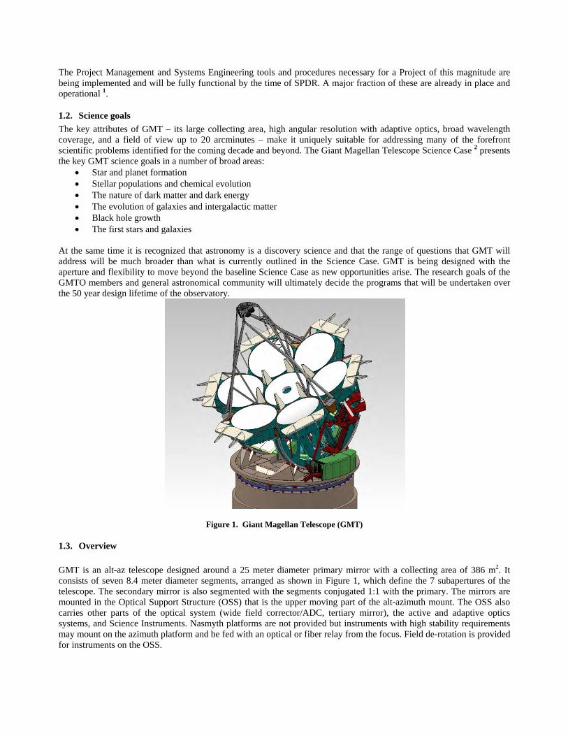
Figure 1. Giant Magellan Telescope (GMT)
1.3. Overview GMT is an alt-az telescope designed around a 25 meter diameter primary mirror with a collecting area of 386 m2. It consists of seven 8.4 meter diameter segments, arranged as shown in Figure 1, which define the 7 subapertures of the telescope. The secondary mirror is also segmented with the segments conjugated 1:1 with the primary. The mirrors are mounted in the Optical Support Structure (OSS) that is the upper moving part of the alt-azimuth mount. The OSS also carries other parts of the optical system (wide field corrector/ADC, tertiary mirror), the active and adaptive optics systems, and Science Instruments. Nasmyth platforms are not provided but instruments with high stability requirements may mount on the azimuth platform and be fed with an optical or fiber relay from the focus. Field de-rotation is provided for instruments on the OSS.
The telescope is designed to operate in various observing modes over a wavelength range from the atmospheric cut-off at around 320 nm in the UV to the mid-IR up to 25 um. The maximum field of view with the corrector is 20 arcminutes at visible and near-IR wavelengths. The corrector/ADC also compensates for atmospheric dispersion. Various observing modes are provided by the active and adaptive optics (AO) systems for instruments designed for a specific wavelength range, field of view, and desired image size. These include:
• Natural seeing – Delivers images to the science instrument with image sizes limited by wavefront distortion of the light from the science targets passing through the atmosphere. Slowly varying effects due to optical misalignment and low frequency (<20 Hz) mechanical vibrations are corrected by the active optics and fast tip/tilt systems.
• Natural guide star AO (NGSAO) -- Delivers high Strehl (>75% K-band), high contrast images over a field of
view limited by natural anisoplanatism using bright guide stars within the isoplanatic patch centered on the guide star.
• Laser Tomographic AO (LTAO) – Delivers moderate Strehl (>30% H-band) with broad sky coverage and field
of view limited by natural anisoplanatism using multiple laser guide stars and one natural guide stars to achieve a high fraction of sky coverage.
• Ground-layer AO (GLAO) – Delivers AO seeing-enhanced images (<0.30 arcsec FWHM in K-band) over a 6.5
arcminute diameter field of view by correcting low-altitude atmospheric turbulence using either laser or natural guide stars for reference.
A varied suite of science instruments will be mounted on GMT at any given time. In general, these will be maintained in “ready mode” and available for use with minimal re-configuration of telescope. Switching between instruments will allow flexible scheduling of observing time and the ability to respond to transient events (“targets of opportunity”) and changing conditions. Stations for 8 instruments are initially provided with the ability to implement others in the future. The first-generation of science instruments will be selected based on a number of criteria: science impact, the ability to cover the full range of observing conditions (seeing, lunar phase, transparency), the scientific interests of the members, and the available budget. Synergy with other existing and future astronomy facilities will also be a factor. Six candidates for GMT’s first-generation instruments were selected from proposals submitted by both internal and external teams. Conceptual designs were completed for each of these and externally reviewed. The reports from the review committees were then evaluated by a selection board to arrive at a list of instruments recommended for further development. In the next phase, the selected instruments will advance through preliminary design 3. The system software controls and data management systems for the GMTO observatory are being developed through the Project Office 4. GMT will be located on Cerro Campanas at Las Campanas Observatory. The facility will include the telescope enclosure, technical and maintenance support buildings, roads and infrastructure, and dining and lodging facilities. The top-level requirements for GMT are contained in the GMT Science Requirements Document (SRD) 5.
2. TELESCOPE
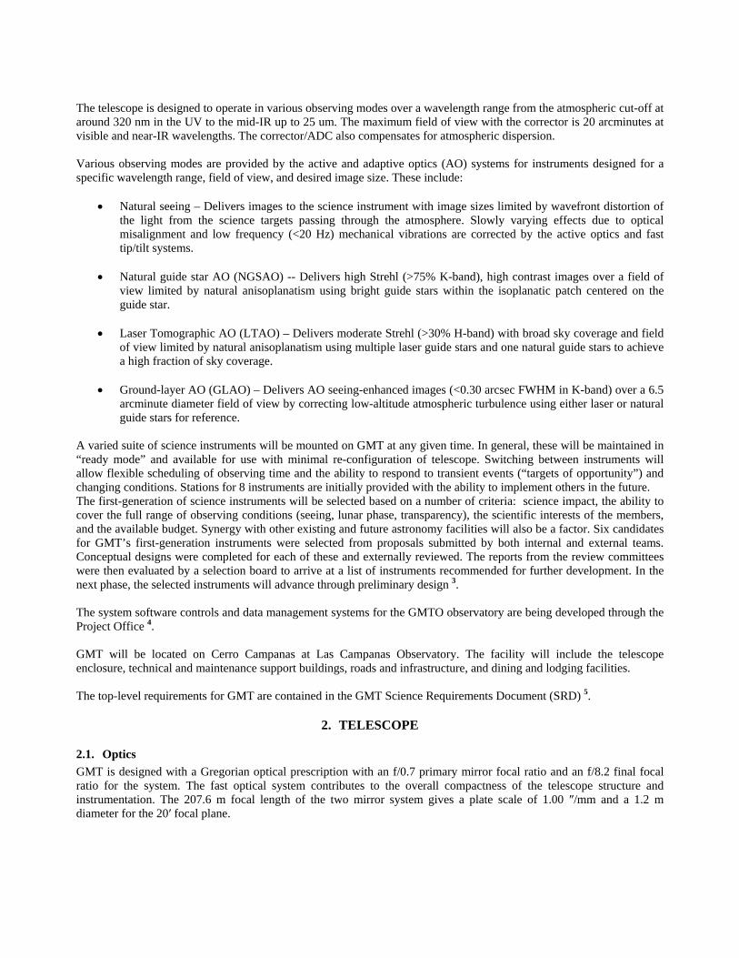
2.1. Optics GMT is designed with a Gregorian optical prescription with an f/0.7 primary mirror focal ratio and an f/8.2 final focal ratio for the system. The fast optical system contributes to the overall compactness of the telescope structure and instrumentation. The 207.6 m focal length of the two mirror system gives a plate scale of 1.00 ″/mm and a 1.2 m diameter for the 20′ focal plane.

Figure 2 Polishing GMT1
The primary mirror segments are made of OHARA E6 glass with a honeycomb structure. They are cast, generated and polished at the University of Arizona Steward Observatory Mirror Lab (SOML) (Figure 2). The first off-axis segment, GMT1, was cast in July 2005. With 14 mm of aspheric departure peak-valley these mirrors are by far the most highly aspheric optics of their size and precision ever made. Fabricating them required the development of a whole new metrology system including redundant surface figure measurements using independent equipment. Much of the effort in producing GMT1 is associated with the development of this metrology, infrastructure and procedures, that are now in place for subsequent GMT segments 6.
Figure 3 GMT1 surface map (13 June 2012)
The segments will be mounted in the telescope on active supports that apply bending forces to maintain the desired mirror figure within limits imposed by the maximum actuator forces that are allowed for figure control. Similar systems have been deployed on previous telescope using the SOML mirrors (MMT, Magellan, LBT). The design and prototyping of the GMT active supports is currently progressing within the project. Sensors in the active optics system continuously measure wavefront aberrations in the focal plane while observing and send the corrections to the segment controller.
120613-20 GMT1 bestEst - 20 modesFull aperture: 18 nm rms, (0.40,8.00) m aperture: 15 nm rms
-200
-150
-100
-50
0
50
100
150
200
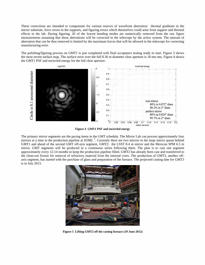
These correcmirror substreffects in thmeasurementaberration thmanufacturin The polishinthe most recethe GMT1 PS
The primary mirrors at a tGMT1 and amirror. GMTapproximatelthe clean-outaxis segmentis in July 201
ctions are intenrate, force erroe lab. During ts assuming that can be thus
ng error.
g/figuring procent surface mapSF and encircle
mirror segmentime in the proahead of the seT segments wly every 12-14t fixture for ret, has started w13.
nded to comprs in the suppofiguring, 20
hat these aberrremoved is lim
cess on GMT1p. The surface ed energy for t
F
nts are the pacioduction pipelinecond GMT of
will be produce months to kee
emoval of refrawith the purchas
Figure 5 L
ensate for varorts, and figuriof the lowest ations will be
mited by the ma
1 is just complerror over the
the full clear ap
Figure 4 GMT1
ing items in thene at SOML 7.ff-axis segmened in a continep the productiactory materialse of glass and
Lifting GMT2 of
rious sources ong errors whicbending modcorrected in t
aximum forces
leted with finafull 8.36 m di
perture.
1 PSF and encir
e GMT schedu Currently ther
nt, GMT2: thenuous series foion pipeline fill from the inte
d preparation o
ff the casting fu
of wavefront ach themselves cdes are numerithe telescope bs that will be al
al acceptance teameter clear ap
rcled energy
ule. The Mirrorre are two mirre LSST 8.4 m following themled. GMT2 has
ernal cores. Thf the furnace. T
urnace (19 June
aberration: thcould arise froically removedby the active sllowed in the t
esting ready toperture is 18 nm
r Lab can procrors in the largmirror and the
m. The plan iss already been
he production oThe projected
e 2012)
ermal gradientom support andd from the rawsystem. The amelescope for co
o start. Figure m rms. Figure
ess approximage mirror queue Mexican SPMs to cast one cast and trans
of GMT3, anocasting date fo
ts in the d thermal w figure mount of orrecting
3 shows 4 shows
tely four e behind M 6.5 m segment ferred to
other off-or GMT3
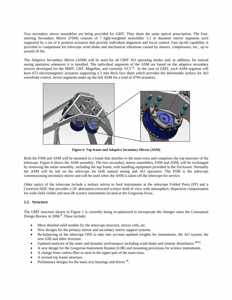
Two secondary mirror assemblies are being provided for GMT. They share the same optical prescription. The Fast-steering Secondary Mirror (FSM) consists of 7 light-weighted monolithic 1.1 m diameter mirror segments each supported by a set of 6 position actuators that provide individual alignment and focus control. Fast tip-tilt capability is provided to compensate for telescope wind shake and mechanical vibrations caused by motors, compressors, etc., up to around 20 Hz. The Adaptive Secondary Mirror (ASM) will be used for all GMT AO operating modes and, in addition, for natural seeing operation whenever it is installed. The individual segments of the ASM are based on the adaptive secondary mirrors developed for the MMT, LBT, Magellan, and currently VLT 8. In the case of GMT, each ASM segment will have 672 electromagnetic actuators supporting a 2 mm thick face sheet which provides the deformable surface for AO wavefront control. Seven segments make up the full ASM for a total of 4704 actuators.
Figure 6 Top frame and Adaptive Secondary Mirror (ASM)
Both the FSM and ASM will be mounted in a frame that attaches to the main truss and comprises the top structure of the telescope. Figure 6 shows the ASM assembly. The two secondary mirror assemblies, FSM and ASM, will be exchanged by removing the entire assembly, including the top frame, with handling equipment provided in the Enclosure. Normally the ASM will be left on the telescope for both natural seeing and AO operation. The FSM is the telescope commissioning secondary mirror and will be used when the ASM is taken off the telescope for service. Other optics of the telescope include a tertiary mirror to feed instruments at the telescope Folded Ports (FP) and a Corrector/ADC that provides a 20′ aberration-corrected science field of view with atmospheric dispersion compensation for wide-field visible and near-IR science instruments located at the Gregorian focus.
2.2. Structure The GMT structure shown in Figure 1 is currently being re-optimized to incorporate the changes since the Conceptual Design Review in 2006 9. These include:
• More detailed solid models for the telescope structure, mirror cells, etc. • New designs for the primary mirror and secondary mirror support systems • Re-balancing of the telescope OSS to take into account updated weights for instruments, the AO system, the
new GIR and other structure. • Updated analyses of the static and dynamic performance including wind shake and seismic disturbance 10 11. • A new design for the Gregorian Instrument Rotator (GIR) and mounting provisions for science instruments. • A change from carbon fiber to steel in the upper part of the main truss. • A revised top frame structure. • Preliminary designs for the main axis bearings and drives 12.

Figure 7 : GMT instruments in the Gregorian Instrument Rotator (GIR).
The GIR re-design is the most significant change since CoDR. The GIR is the large instrument-carrying structure located below the primary mirror that rotates about the telescope optical axis to compensate for field rotation caused by the alt-azimuth tracking of the telescope. Science Instruments are mounted at the Direct Gregorian (DG) focus inside the GIR and at ports (“Folded Ports”) on the top surface. A deployable steering mirror (tertiary mirror) directs the beam to the FP instruments. DG instruments are exchanged with a shuttle mechanism that moves the instruments into the beam from their stow positions in bays within the GIR. Four bays are provided, each able to accommodate a Science Instrument up to 2.8 m x 2.8 m x 5.5 m high and 11,500 kg. The top surface of the GIR is 9 m in diameter and divided in four quadrants: three for FP Science Instruments and the fourth for the tertiary mirror and GLAO wavefront sensor assemblies. The maximum FP instrument is 3.5 m x 5.5 m x 1.9 m high and 6,500 kg. The GIR also houses the Acquisition and Guide Assembly with guide cameras and wavefront sensors for the telescope active optics (AcO) system and Phasing Camera for the AO System. An additional gravity-invariant instrument station (GIS) is provided on the top surface of the azimuth disk. An optical relay using either re-imaging optics, fiberoptic feed, or a combination of both is required to bring light to this station.
3. ADAPTIVE OPTICS
3.1. AO modes The Adaptive Optics System (AOS) will provide several AO observing modes to science instruments. The objective is to maximize the scientific productivity of the instruments while minimizing replication of functionality within the AOS. The capabilities are the following:
• Natural Guide Star AO (NGSAO): The Natural Guide Star Adaptive Optics (NGSAO) observing mode uses a single star and wavefront sensor to provide all of the wavefront correction information for the AO System. The wavefront aberration will be compensated by the ASM, providing diffraction-limited imaging at 0.9-25 µm wavelength over a field of view limited by atmospheric isoplanatism 13 14. The requirement is for a K-band Strehl of >75% and L’-band contrast ratios of >105 at 0.12 arcseconds radius (4λ/D).
• Laser Tomography AO: (LTAO) The Laser Tomography Adaptive Optics (LTAO) observing mode uses a ~1 arcmin. diameter constellation of 6 LGS to tomographically reconstruct the high-order components of the atmospheric wavefront aberrations in the direction of a central science target. One faint natural guidestar is used to

measure tip-tilt, focus, segment piston, and dynamic calibration terms. The wavefront aberration will be compensated by the ASM, providing diffraction-limited imaging at 0.9-25 µm wavelength over a field of view limited by atmospheric isoplanatism 15 16 17. The requirement is for an H-band Strehl of >30% over 50% of the sky at the galactic pole.
• Ground Layer AO (GLAO): The Ground-Layer Adaptive Optics (GLAO) observing mode uses a guidestar asterism (either LGS/NGS or NGS-only) to detect and correct wavefront errors common to sky objects within a large (up to 10 arcmin in diameter) field of view. These errors are mainly due to low (up to 1 km) altitude turbulent layers of the atmosphere. The wavefront aberration will be detected using multiple wavefront sensors and compensated by the ASM, resulting in improved natural seeing images over a field of view comparable to the GS constellation size. While providing some improvement in the visible, GLAO correction is expected to be particularly useful at wavelengths longer than 1 µm 18. The requirement is for a median image size in K band of less than 0.30 arcsec FWHM.
The AO requirements are described more fully by Trancho, et. al. 19.
3.2. AO architecture The GMT AO system design is based on an adaptive secondary mirror (ASM), and wavefront sensor assemblies (“AO front end”) replicated for each instrument 20. Figure 8 shows the layout of the AO system components. All narrow-field AO instruments (those using the NGSAO and LTAO observing modes) are located at a folded port (FP) focus and selected with a steerable tertiary mirror. Each instrument cryostat window is a long-pass dichroic and all visible-light wavefront sensing (LGS and NGS) is performed in the beam reflected by the window. This design provides very high throughput and low emissivity, with only 3 reflections between the sky and the science instrument.
Figure 8 AO System Layout

The GLAO ofocus. The Anatural guidepick-off and High-order wAn extensivecurrent basellocated at thedesigns close Figure 9 show
Figure 9 (
3.3. Phasing Achieving thnm RMS. Duwith a non-ztimescales lopiston at up therefore desinitially phasa high-sensitsegments areloaded to the
4.1. Instrum Conceptual DTable 1. Thoand deploymgeneration in
observing modAO system therestars with a lawavefront sen
wavefront sensie trade study cline uses six 2e ends of the stely follow the V
ws block diagr
(Left) Block diag
g system
he diffraction lue to the large zero CTE, cap
onger than a fewto 1 kHz. How
signed a 3-stagse the telescopetivity optical se matched one-e primary or sec
ment concepts
Design studies ose marked "*"ment on GMT wnstruments will
de is used only refore providesarge dichroic ansor assembly (
ing in the LTAcompared the
20 Watt Ramantiff primary miVery Large Te
rams of the AO
gram of the NGSdashed a
imit of the 25.separation betpacitive or inw minutes. In wever, only fage phasing syste, primary and sensor to correto-one, errors condary segme
s
for six candid have been sel
will be decidedl be selected by
by wide-field s a single GLAnd pick-off miLGLAOS) is s
AO and GLAOexpected perfo
n fiber lasers tirror cell connlescope AO Fa
O modes.
SAO and LTAOarrows. (Right) B
.4 m GMT wiltween primary
nductive edge the NGSAO o
aint natural gutem consistingsecondary mir
ect long-term dcan be rapidly ent positioning
4. INSTR
date instrumentected to advan
d on the basis oy the GMT Sci
instruments wAO wavefront sirrors ahead of shown in Figur
O observing moformance of onto be coupled ector frame asacility design.
modes. Light paBlock diagram o
ll require the psegments (30-sensors alone
observing modeuidestars are geg of a coarse oprror edge sensodrifts in the edcompensated u actuators as ap
RUMENTAT
ts are completence through a pof science impientific Adviso
which can be desensing assemb
f the instrumenre 8.
odes will be prn-axis and off-directly to six shown in Figu
aths are shown wof the GLAO mo
primary and se-40 cm) and th
e are not expee, the NGSAOenerally availaptical phasing
ors to maintain dge sensors 21
using the agileppropriate.
TION
e. The list andpreliminary despact, cost, schery Committee
eployed at the bly, interceptin
nt entrance win
rovided by 6 sof-axis LGS laux 38 cm refracture 8. The lase
with wide arrowode.
condary mirroheir constructioected to be su WFS can sens
able in the LTAsensor with a alignment ove
22. Since the pe adaptive seco
d instrument pasign study. Theedule, and avai(SAC) starting
direct Gregoring laser guides
ndow. The lase
odium laser guunch architectutive launch teler and launch t
s, control signal
rs to be phaseon of borosilicufficiently stabse and correct AO mode. GMlarge capture
er short timescaprimary and seondary mirror, t
arameters are se order of deveilable budget 3
g in 2015.
ian (DG) stars and
er GLAO
uidestars. ures. The lescopes, elescope
s with
d to <50 ate glass ble over segment
MTO has range to ales, and econdary then off-
shown in elopment . Second

Instrument Function λ Range, μm
Resolution Field of View Loc Ref GMACS * Optical Multi-Object Spectrometer 0.36 – 1.0 1500 – 4000, 10,000 40 – 80 arcmin2 DG 23 24 25 NIRMOS Near-IR Multi-Object Spectrometer 0.9 – 2.5 2700 – 5000 42 arcmin2 DG 26 G-CLEF* Optical High Resolution Spectrometer 0.35 – 0.95 20 – 100K 7 x 1” fibers GIS 27 GMTNIRS* Near-IR AO-fed High Resolution Spectrometer 1.2 – 5.0 50 – 100K Single Object FP TIGER Mid-IR AO-fed Imager and Spectrometer 1.5 – 14 300 0.25 arcmin2 FP 28 GMTIFS* NIR AO-fed IFU / Imager 0.9 – 2.5 4000 – 10,000 10 / 400 arcsec2 FP 29 MANIFEST* Facility Robotic Fiber Feed 0.36 – 1.0 300 arcmin2 DG 30
Table 1 Science Instrument concepts
Instruments will be mounted at the DG, FP or GIS station as described above. A facility robotic multi-fiber feed to provide wide-field coverage for the optical and near-IR spectrographs is also planned. The GMT instruments and instrumentation development plan are described in the references in Table 1 and by Jacoby, et. al3.
5. ENCLOSURE AND FACILITIES
Figure 10 GMT Enclosure and Summit Facility
5.1. Site GMT will be located on Cerro Campanas at Las Campanas Observatory (LCO). LCO is at the southern end of the Atacama Desert, approximately 170 km north of the coastal city of La Serena. Observing conditions at LCO are excellent with a high fraction of clear nights and good seeing. These are documented in the final report of the site characterization campaign and borne out through many years of observatory operation 31. Figure 11 shows LCO with Cerro Campanas on the left and the Manquis ridge to the right where the Magellan 6.5 m telescopes, DuPont 100” telescope and Swope 40” telescope are located. The distance from the LCO lodge and Magellan telescopes to Cerro
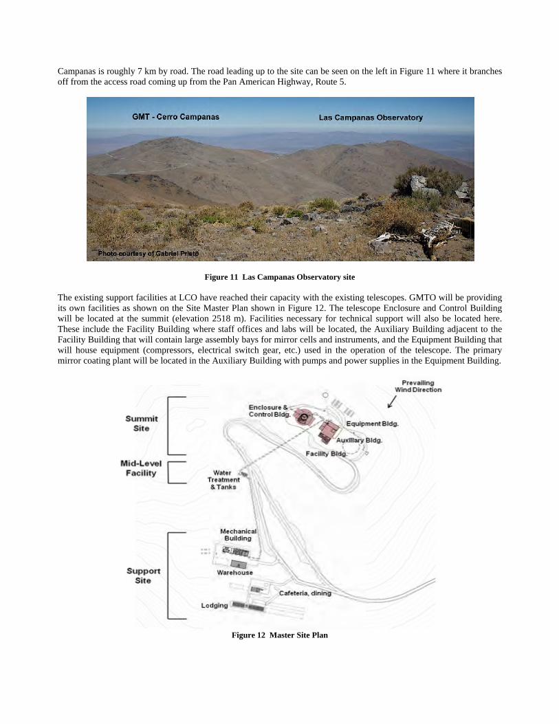
Campanas is off from the a
The existing its own faciliwill be locatThese includFacility Buildwill house emirror coatin
roughly 7 km access road co
support facilitities as shownted at the summde the Facility ding that will cquipment (com
ng plant will be
by road. The rming up from
F
ties at LCO hav on the Site Mmit (elevation Building wher
contain large ampressors, elece located in the
road leading upthe Pan Ameri
Figure 11 Las C
ve reached theMaster Plan sho
2518 m). Facre staff offices
assembly bays fctrical switch
e Auxiliary Bui
Figure 12
p to the site canican Highway,
Campanas Obse
eir capacity witown in Figure cilities necessas and labs will for mirror cellsgear, etc.) use
ilding with pum
2 Master Site P
n be seen on thRoute 5.
ervatory site
th the existing 12. The telesc
ary for technicbe located, th
s and instrumeed in the opermps and power
Plan
he left in Figur
telescopes. GMcope Enclosureal support wil
he Auxiliary Buents, and the Eqration of the ter supplies in th
re 11 where it b
MTO will be pe and Control Bl also be locatuilding adjacenquipment Buildelescope. The e Equipment B
branches
providing Building ted here. nt to the ding that primary
Building.

A support area with warehouse and mechanical shops, and a dining hall and lodging will be located 134 m and 157 m below the summit respectively. LCO has a reliable source of water that is pumped up to a cistern on the site from a well at the base of the mountain. Water treatment will be provided locally at the facility. Electrical power will be brought up from commercial sources at the base of the mountain on high voltage overhead lines. An existing 23KV line provides power to LCO. The service will have to be significantly upgraded in order to supply GMT’s estimated 1.5MW average load. Commercial power will be backed up by diesel generators. Clearing and leveling of the site started March 23, 2012. Approximately 55,000 m3 of rock and soil is being cut. Approximately 20,000 m3 of that will be used as fill on the site. The work will be completed in August. The platform when cleared will measure approximately 280 m long by 100 m wide. Figure 13 shows the site in May.
Figure 13 Clearing the GMT site. May 2012.
5.2. Enclosure The GMT Enclosure is a quasi-cylindrical structure that houses the telescope. Large doors (“shutters”) in front and on top of the building retract to allow the telescope to observe with an unobstructed beam through its full range of azimuth and elevation angle. During observing, the shutters can be closed down around the incoming beam to shield the telescope from excessive wind and moonlight. The enclosure is comprised of a rotating upper structure that sits on top of a fixed base. The range of rotation is unlimited allowing the shutters to be aligned with the telescope for any arbitrary azimuth setting of GMT. The telescope and enclosure rotate independently of each other through their full range of motion. A circular track at the top of the fixed base (the “ring beam”) and bogies beneath the major structural columns of the upper structure provide the rotation mechanism. The overall height of the enclosure is 65 m above grade level. The Ring Beam is 14.8 m above grade and approximately level with the top of the GMT azimuth disk and Observing Floor. This puts the elevation axis of GMT at 25.5 m. A 75 metric ton bridge crane at the top of the enclosure will be used in the initial assembly of GMT and for servicing the telescope and equipment during operations. In particular, the crane will be used to exchange primary mirror segments and cells in the telescope for re-coating in the Auxiliary Building. It will also be used for instrument handling.
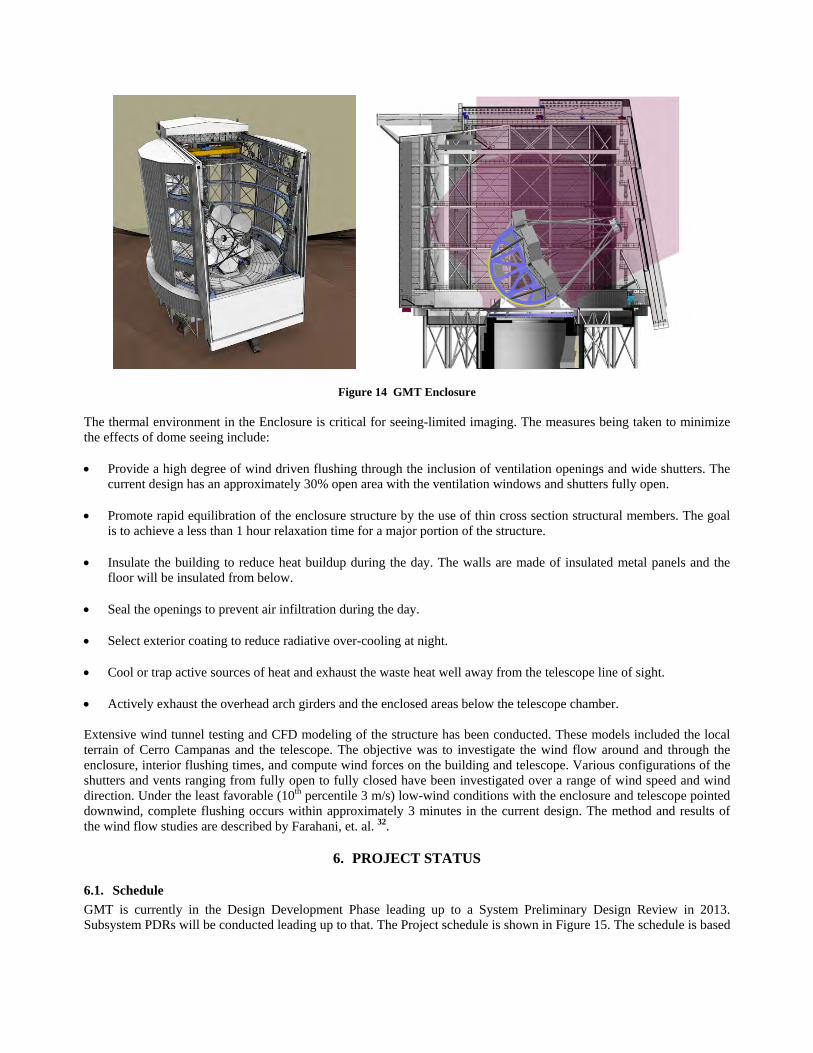
Figure 14 GMT Enclosure The thermal environment in the Enclosure is critical for seeing-limited imaging. The measures being taken to minimize the effects of dome seeing include: • Provide a high degree of wind driven flushing through the inclusion of ventilation openings and wide shutters. The
current design has an approximately 30% open area with the ventilation windows and shutters fully open. • Promote rapid equilibration of the enclosure structure by the use of thin cross section structural members. The goal
is to achieve a less than 1 hour relaxation time for a major portion of the structure. • Insulate the building to reduce heat buildup during the day. The walls are made of insulated metal panels and the
floor will be insulated from below. • Seal the openings to prevent air infiltration during the day. • Select exterior coating to reduce radiative over-cooling at night. • Cool or trap active sources of heat and exhaust the waste heat well away from the telescope line of sight.
• Actively exhaust the overhead arch girders and the enclosed areas below the telescope chamber. Extensive wind tunnel testing and CFD modeling of the structure has been conducted. These models included the local terrain of Cerro Campanas and the telescope. The objective was to investigate the wind flow around and through the enclosure, interior flushing times, and compute wind forces on the building and telescope. Various configurations of the shutters and vents ranging from fully open to fully closed have been investigated over a range of wind speed and wind direction. Under the least favorable (10th percentile 3 m/s) low-wind conditions with the enclosure and telescope pointed downwind, complete flushing occurs within approximately 3 minutes in the current design. The method and results of the wind flow studies are described by Farahani, et. al. 32.
6. PROJECT STATUS
6.1. Schedule GMT is currently in the Design Development Phase leading up to a System Preliminary Design Review in 2013. Subsystem PDRs will be conducted leading up to that. The Project schedule is shown in Figure 15. The schedule is based
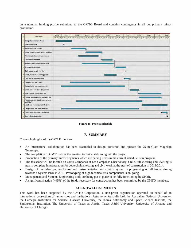
on a nominal funding profile submitted to the GMTO Board and contains contingency in all but primary mirror production.
Figure 15 Project Schedule
7. SUMMARY Current highlights of the GMT Project are: • An international collaboration has been assembled to design, construct and operate the 25 m Giant Magellan
Telescope. • The completion of GMT1 retires the greatest technical risk going into the project. • Production of the primary mirror segments which are pacing items in the current schedule is in progress. • The telescope will be located on Cerro Campanas at Las Campanas Observatory, Chile. Site clearing and leveling is
nearly complete in preparation for geotechnical testing and civil work at the start of construction in 2013/2014. • Design of the telescope, enclosure, and instrumentation and control system is progressing on all fronts aiming
towards a System PDR in 2013. Prototyping of high technical risk components is on-going. • Management and Systems Engineering tools are being put in place to be fully functioning by SPDR. • A significant fraction (~45%) of the funds necessary for construction has been committed by the GMTO members.
ACKNOWLEDGEMENTS This work has been supported by the GMTO Corporation, a non-profit organization operated on behalf of an international consortium of universities and institutions: Astronomy Australia Ltd, the Australian National University, the Carnegie Institution for Science, Harvard University, the Korea Astronomy and Space Science Institute, the Smithsonian Institution, The University of Texas at Austin, Texas A&M University, University of Arizona and University of Chicago.

This material is based in part upon work supported by AURA through the National Science Foundation under Scientific Program Order No. 10 as issued for support of the Giant Segmented Mirror Telescope for the United States Astronomical Community, in accordance with Proposal No. AST-0443999 submitted by AURA.
REFERENCES
[1] Maiten, J., Johns, M. W., Trancho, Saywer, D., G., Mady, P., “Systems engineering implementation in the preliminary design phase of the Giant Magellan Telescope,”, Proc. SPIE 8449-05, (2012).
[2] McCarthy, P. J. (ed.), “GMT Science Case”, GMTO document GMT-SCI-DOC-00031 (2006).
[3] Jacoby, G. H., Bouchez, A. H., Colless ,M., DePoy,D. L., Fabricant, D. G., Hinz, P. M., Jaffe, D. T., Johns, M., McCarthy, P. J., McGregor, P. I., Shectman, S. A., Szentgyorgyi, A. H., “The instrument development and selection process for the Giant Magellan Telescope (Invited Paper),” Proc. SPIE 8446-50, (2012).
[4] Filgueira, J. M., Bec, M., Soto, J., Liu, N., “GMT software and controls overview,” Proc. SPIE 8451-131, (2012).
[5] McCarthy, P. J. (ed.), “GMT Science Requirements Document (SRD)”, GMT-SCI-REQ-00001 (2010).
[6] Su, P., Wang, S., Khreishi, M., Zobrist, T., Martin, H., Burge, J. H., “SCOTS: a large dynamic range reverse Hartmann test for Giant Magellan Telescope primary mirrors,” Proc. SPIE 8450-31, (2012).
[7] Martin, H. M., Allen, R. G., Burge, J. H., Brian Cuerden, B., Kim, D. W., Kingsley, J. S., Law, K., Lutz, R., Strittmatter, P. A., Peng Su, P., Tuell, T., Warner, S., West, S. C., Zhou, P., “Production of 8.4 m segments for the Giant Magellan Telescope,” Proc. SPIE 8450-90, (2012).
[8] Biasi, R., Andrighettoni, M., Angerer, G., Mair, C., Pescoller, D., Lazzarini, P., Anaclerio, E., Mantegazza, M., Gallieni, D., Vernet, E., Arsenault, R., Madec, P.Y., Duhoux, P., Riccardi, A., Xompero, M., Briguglio, R., Manetti, M., Morandini, M., “VLT deformable secondary mirror: integration and electromechanical tests results”, Proc. SPIE 8447-88 (2012).
[9] Sheehan, M., Gunnels, S., Johns, M. W., Hull, C. L., Kern, J., Shectman, S. A., “Progress on the preliminary structural and mechanical design of the Giant Magellan Telescope,” Proc. SPIE 8444-22, (2012).
[10] Glaese, R. M., Michael Sheehan, M., “Vibration mitigation for wind-induced jitter for the Giant Magellan Telescope,” Proc. SPIE 8444-30, (2012).
[11] Kan, F. W., Sarawit, A. T., Cranston, P. G., “Modeling seismic behavior of static supports of Giant Magellan Telescope (GMT),” Proc. SPIE 8444-114, (2012).
[12] Beets, T. A., Beno, J. H., Worthington, M. S., “GMTNIRS mechanical design,” Proc. SPIE 8446-301, (2012).
[13] Esposito, S., Pinna, E., Quirós-Pacheco, F., Puglisi, A. T., Carbonaro, L., Bonaglia, M., Biliotti, V., Briguglio, R., Agapito, G., Arcidiacono, C., Busoni, L., Xompero, M., Riccardi, A., Fini, L., Bouchez, A., “Wavefront sensor design for the GMT natural guide star AO system,” Proc. SPIE 8447-57, (2012).
[14] Esposito, S., Pinna, E., Quirós-Pacheco, F., Puglisi, A. T., Carbonaro, L., Bonaglia, M., Biliotti, V., Briguglio, R., Agapito, G., Arcidiacono, C., Busoni, L., Xompero, M., Riccardi, A., Fini, L., Bouchez, A.“Wavefront sensor design for the GMT natural guide star AO system,” Proc. SPIE 8447-57, (2012).
[15] van Dam, M. A., Conan, R., Bouchez, A. H.,Espeland, B., “Design of a truth sensor for the GMT laser tomography adaptive optics system,” Proc. SPIE 8447-43, (2012).
[16] Conan, R., van Dam, M. A., Espeland, B., Uhlendorf, K., Piatrou, P. K., Bennet, F. H., Bouchez, A., “The Giant Magellan Telescope laser tomography adaptive optics system,” Proc. SPIE 8447-135, (2012).
[17] Wang, M., Kristina Uhlendorf, K., Jones, D. J., Côté, P., Châteauneuf, F., Gauvin, J., Conan, R., Espeland, B., “Optical designs with LGS WFS system for GMT-LTAO,” Proc. SPIE 8447-136, (2012).
[18] Hinz, P. M., Brusa-Zappellini, G., Vaitheeswaran, V., McMahon, T., Connors, T., Knox, R. P., Montoya, M., Bouchez, A. H., “Design and predicted performance of the GMT ground-layer adaptive optics mode”, Proc. SPIE 8447-136, (2012).
[19] Trancho, G., Espeland, B., Bouchez, A. H., Conan, R., Hinz, P. M., van Dam, M. A., “GMT AO system requirements and error budgets in the preliminary design phase,” Proc. SPIE 8447-202, (2012).
[20] Bouchez, A., Acton, D.S., Bennet, F. H., Brusa-Zappellini, G., Codona, J. L., Conan, R., Connors, T., Durney, O., Espeland, B.,Gauron, T. M., Lloyd-Hart, M., Hinz, P. M., Kanneganti, S., Kibblewhite, E. J., Knox, R. P., McLeod, B. A., McMahon, T., Montoya, M., Norton, T. J., Ordway, M. P., Parcell, S., Piatrou, P. K., Price, I., Roll, Jr., J. B., Trancho, G., Uhlendorf, K., et al, “The Giant Magellan Telescope adaptive optics program”, Proc. SPIE 8447-54, (2012).
[21] Bouchez, A. H., McLeod, B. A., Acton, D. S., Kanneganti, S., Kibblewhite, E. J., Shectman, S. A., van Dam, M. A., ” The Giant Magellan Telescope phasing system,” Proc. SPIE 8447-138, (2012).
[22] Kanneganti, S., McLeod, B. A., Ordway, M. P., Shectman, S. A., Bouchez, A. H., Codona, J., Eng, R., Gauron, T. M., Norton, T. J., Roll, Jr., J. B., Streechon, P., Weaver, D., “A prototype phasing camera for the Giant Magellan Telescope,” Proc. SPIE 8447-187, (2012).
[23] DePoy, D. L., Marshall, J. L., Prochaska, T., Behm, T. W., Smee, S. A., Barkhouser, R. H., Hammond, R. P., Shectman, S. A., Papovich, C., “The GMACS spectrograph for the Giant Magellan Telescope,” Proc. SPIE 8446-58, (2012).
[24] Barkhouser, R. H., Shectman, S. A., DePoy, D. L., Marshall, J. L., Smee, S. A. Hammond. R. P., Prochaska, T.,“Conceptual optical design for GMACS, a wide-field, multi-object, moderate resolution optical spectrograph for the Giant Magellan Telescope (GMT),” Proc. SPIE 8446-293, (2012).
[25] Smee, S.A., Prochaska, T., Shectman, S. A., Hammond, R. P., Barkhouser, R. H., DePoy, D. L., Marshall, J. L., “Optomechanical design concept for GMACS: a wide-field multi-object moderate resolution optical spectrograph for the Giant Magellan Telescope (GMT),” Proc. SPIE 8446-294, (2012).
[26] Fabricant, D. G., Fata, R. G., Brown, W. R., McLeod, B. A., Mueller, M., “NIRMOS: a wide-field near-infrared spectrograph for the Giant Magellan Telescope,” Proc. SPIE 8446-59, (2012).
[27] Szentgyorgyi, A., Frebel, A., Furesz, G., Hertz, E. N., Norton, T. J., Bean, J., Bergner, H. W., Crane, J.D., Evans, J. D., Evans, I. N., Gauron, T. M., Jordan, A., Park, S. C., Uomoto, A., Barnes, S. I., Davis, W., Eisenhower, M., Epps, H. W., Guzman, D., McCracken, K., Ordway, M. P., Plummer, D. A., Podgorski, W. A., Weaver, D. S., “The GMT-CfA, Carnegie, Catolica, Chicago Large Earth Finder (G-CLEF): a general purpose optical echelle spectrograph for the GMT with precision radial velocity capability,” Proc. SPIE 8446-52, (2012).
[28] Hinz, P. M., Codona, J. L., Guyon, O., Hoffmann, W. F., Skemer, A., Hora, J. L., Tolls, V., Boss, A., Weinberger, A., Arbo, P., Connors, T., Durney, O., McMahon, T., Montoya, M., Vaitheeswaran, V., “TIGER: a high contrast infrared imager for the Giant Magellan Telescope,” Proc. SPIE 8446-60, (2012).

[29] McGregor, P. J., Bloxham, G. J. Boz, R., Davies, J., Doolan, M. C., Ellis, M., Hart, J., Nielsen, J. J., Parcell, S., Sharp, R. G., Stevanovic, D., “The GMT integral-field spectrograph (GMTIFS) conceptual design,” Proc. SPIE 8446-53, (2012).
[30] Goodwin, M., Colless, M., Monnet G. J., Saunders, W., Lawrence, J. S., Hopkins, A. Brzeski, J. K., Case, S., Farrell, T. J. Gers, L., Gilbert, J., Heijmans, J., Miziarski, S., Muller, R., Smith, G. A., Tims, J., Waller, L. G., “MANIFEST instrument concept and related technologies,” Proc. SPIE 8446-289, (2012).
[31] Thomas-Osip, J. (ed.), “GMT Site Testing at Las Campanas Observatory – Final Report”, GMT document GMT-SE-DOC-00114 (2011).
[32] Farahani, A. Kolesnikov, A., Cochran, L., Hull, C., Johns, M., “GMT Enclosure Wind and Thermal Study”, Proc. SPIE 8444-29, (2012).