Embed Size (px)
Citation preview

Volume 1 • Issue 2 • 1000104J Appl Computat MathISSN: 2168-9679 JACM, an open access journal
Open AccessResearch Article
Applied & Computational Mathematics
Keywords: Radial porous burner; Axial porous burner; Emissions;Speed reduction
Nomenclature Greek symbols
A Cross-section area λ Heat conductivity
Cp Heat capacity at constant pressure aσ Absorption factor
Hv Volumetric heat transfer between sσ Scattering albedo
gas and solid phases
I Radiation intensity β Extinction coef-ficient
m Flow rate ε Emissivity
P Pressure Ω ace angle
qrad Radiative heat flux ϕ porosity
R Gas constant φ Equivalence ratio
r Radial direction
s Space direction Φ Phase function
T Temperature ω Production rate
Nomenclature subscripts
u Velocity s Solid
V Diffusion velocity k Species counter
W Molecular weight in inlet
x Axial coordinate out outlet
Y Mass fraction Sur Surround
g gas
IntroductionOne of the possible configurations for porous burners is cylindrical
configuration. In this configuration, two types of flows can be assumed; one is a flow which moves in the burner axially. This type of flow was
investigated by Khosravy et al. [1] in cylindrical geometry and the ef-fect of pressure drop was studied on performance of burner. In another study, they also investigated the effect of lateral heat conduction in cy-lindrical geometry with axial flow [2].
Since combustion causes a sudden increase in temperature, as a result density decreases, therefore because of continuity the speed of gases increases suddenly, this leads to instability in flame formation. In porous burners, increasing the cross-section of the burner after flame zone is one of the proposed solutions, but increase in cross section causes dispersions in the movement pattern of the flow and the control of which is sometimes difficult. Porous burners with radial flow are able to overcome this problem, because combustion inside porous medium with radial flow causes to a decrease in speed by increase in radius. Kamal and Mohammad suggested this type of flow for improvement of flame stabilization and better heat recycling in burners [3]. In ad-dition to radial flow in cylindrical geometry and radial flow in spheri-cal geometry is also presented with regards to improvement in flame stabilization [4].
In other words, for high inlet speeds for which a stable flame can-not be achieved in axial burners, in radial burner a stable flame can be formed. These kinds of burners have other advantages too, like reduc-tion in CO emission. The major reason of which is the decrease of speed in the direction of radius and as a result an increase in residence time. Also one of the geometric advantages of such a system is the small and compact size of the burner in comparison to a burner with axial flow.
Several numerical solutions have been proposed for porous burner with radial flow. Zhdanok et al studied flame stability in cylindrical and
*Corresponding author: N. Ghiasi Tabari, Islamic Azad University-Dashtestan branch, Iran, E-mail: [email protected]
Received February 13, 2012; Accepted April 24, 2012; Published April 28, 2012
Citation: Ghiasi Tabari N, Astaraki MR, Arabi AH (2012) The Comparison of Radial and Axial Flow Porous Burners from Viewpoint of Output Radiative Heat Transfer and Emissions. J Appl Computat Math 1:104. doi:10.4172/2168-9679.1000104
Copyright: © 2012 Ghiasi Tabari N, et al. This is an open-access article distributed under the terms of the Creative Commons Attribution License, which permits unrestricted use, distribution, and reproduction in any medium, provided the original author and source are credited.
AbstractIn this paper, two types of porous burners with radial and axial flow have been modeled numerically and
compared. For this purpose, governing equations were solved one-dimensionally for methane-air premix gas. The mechanism used in simulating combustion phenomenon was 15 stage reduced mechanism based on GRI3.0. In order to compare the two burners, the inlet flow rate and fuel-air ratio have been assumed equal for the two burners. The results of the study indicated that reduction in speed and increase in cross-section area in the direction of flow have a considerable influence on the behavior of radial burner in comparison to axial burner. Regarding temperature distribution inside the burner, it was observed that the two above mentioned factors can be influential in temperature of flame propagation region. Also, regarding distribution of CO and NO emission, the results indicate that the porous radial burner has lower emissions in comparison to the axial once. The output radiative heat transfer efficiency of the two burners was also compared and in this case also even the radial porous burner was found to be preferable.
The Comparison of Radial and Axial Flow Porous Burners from Viewpoint of Output Radiative Heat Transfer and EmissionsN. Ghiasi Tabari1*, M. R. Astaraki and A. H. Arabi1Islamic Azad University-Dashtestan branch, Iran
Ghiasi Tabari et al., J Appl Computat Math 2012, 1:2 DOI: 10.4172/2168-9679.1000104
Citation: Ghiasi Tabari N, Astaraki MR, Arabi AH (2012) The Comparison of Radial and Axial Flow Porous Burners from Viewpoint of Output Radiative Heat Transfer and Emissions. J Appl Computat Math 1:104. doi:10.4172/2168-9679.1000104
Page 2 of 5
Volume 1 • Issue 2 • 1000104J Appl Computat MathISSN: 2168-9679 JACM, an open access journal
spherical porous burners and compared flame stability in cylinder and sphere [5]. They proposed an analytical solution for the problem with one-temperature assumption; in fact they assumed that the volumetric internal heat transfer coefficient is infinite. Also, they solved the prob-lem with two-temperature model and using Arrhenius form for mod-eling combustion numerically. In their analytical solution, for some values of inlet flow rate two radii were obtained for stabilization point, in a way that if ignition happens between these two points, the flame forming region tends toward the shorter radius. They also found that in spherical coordinate in order to have a stable flame inside porous area, a longer length should be preheated in comparison to that in cylinder. In another paper Zhdanok et al analyzed the effect of medium trans-parency on the performance of cylindrical and spherical porous burner [6]. The results of the study showed that output radiation efficiency is more for transparent material. They also studied the effect of trans-parency of medium on maximum temperature of porous medium and found out that the maximum temperature for a transparent material is 50 to 150 Kelvin less [7]. In both numerical solutions mentioned above, single-step chemical kinetics was used for simulation of combustion and just the stability of the flame was dealt with and nothing was dis-cussed about the effect of this radial flow on emissions.
Kamal and Mohammad performed an experimental study on porous burner with radial flow [3]. In their study, they reported tem-perature distribution, emissions, and output radiative heat transfer efficiency and also investigated the effect of swirl of flow on burner performance. Their experimental study results indicated that because of decrease in speed in the direction of flow and more radiative heat transfer in porous medium, the radial flow in porous burner can also cause a decrease in emissions.
In the present paper two porous burners, one with axial flow and the other with radial flow have been simulated numerically and have been compared from various viewpoint like speed, temperature, emis-sions and output radiative heat transfer efficiency. In order to study the governing equations have been solved one-dimensionally, One-dimen-sional assumption has acceptable precision to predict the behavior of an actual porous burner whit isolated lateral walls [2]. Also comparison has been performed by taking into account equal fuel flow rate and fuel-air ratio for two porous burners.
The Governing Equations and Solution MethodThe governing equations generally include continuity, gas and sol-
id energy, radiative transfer equation (RTE), gas species and gas state equation.
( ) 0d uAdx
ρ ϕ = continuity (1)
1
.
1
1
( ) 0
Kg g g
s k k pkkpg p g
K
k k k V s gkpg
dT dT dTd AuA A Y V cdx c dx dx c dx
A h W A H T Tc
ρ ϕ λ ϕ ϕ ρ
ϕ ω ϕ
=
=
− +
+ − − =
∑
∑ gas energy (2)
( )1 ( ) 0s s rads s s V s g
ps
dT d A qd A A H T Tc dx dx dx
λ − − − = Solid energy (3)
4
ˆ( , ) ˆ ˆ ˆ ˆ( , ) ( , ) ( , )4
sa b
dI r s I r s I I r s s s dds π
σβ σπ
′ ′= − + + Φ Ω∫
Radiative
transfer(4) equation
.( ) 0, ( 1,....., )k
kk k kdY duA A Y V A W k Kdx dx
ρ ϕ ρ ϕ ϕω+ − = = Gas species (5)
pWRT
ρ = gas state (6)
In equation 3, term radq is the radiative heat flow, which is calcu-
lated from equation
4
4
(4 ),rada
dq T G G Iddx π
σ σ= − = Ω∫
(7)
In the equations above, when the burner has axial flow, the cross section of flow (A) is constant, and when the burner has radial flow, the cross section of flow is variant and is equal to A=2πx.
In order to solve the equations above, the famous PREMIX code from CHEMKIN group which was originally used for simulating one-dimensional free and laminar flame [8] was developed for simulating combustion inside porous media. For this purpose solid Energy and ra-diative transfer equations were added to the set of the above mentioned solvable equations by PREMIX code. Also some changes were made in PREMIX gas energy equation in order to solve combustion in porous media in PREMIX code. Solving the equations is done in three stages:
First, a chemical species distribution is found by using a tempera-ture preliminary guess. In the second stage, by using distribution ob-tained from first stage as preliminary guess, energy, species, and con-tinuity equations are solved without taking into account the radiation and in the last stage, all equations are solved implicitly by using the previous stage results as preliminary guess.
In order to solve radiative transfer equation, the Discrete Ordinates Method (DOM) was used. In this method, radiative heat transfer equa-tion is transformed into partial differential equations set, in which each equation is written for one space direction. The summation of these directions should cover a sphere with 4 πspace degrees.
According to studies done on combustion mechanisms, a suitable chemical kinetic was chosen which was suitable from viewpoint of cal-culations time and precision of results [9]. Khosravy et al. investigated Precision of GRI3.0 and Miller reduced mechanism in comparison to full mechanism [10], their study was displayed satisfactory agreement between 15 stages reduced mechanism based on GIR3.0 in comparison to GRI3.0 mechanism. In this study the mechanism used in simulation are 15 stage reduced mechanism based on GRI3.0.
Boundary conditions of equations 1-6 is shown in Table 1.
The Geometry of Radial and Axial Porous BurnersA schematic picture of two axial (a) and radial (b) flow porous
burners has been showed in Figure 1. The burner which was experi-mented in Kamal and Mohammad [3] study had external and internal radii of 3 and 1 centimeter and the same values were kept in this study for modeling. The thickness of axial burner is also 2 centimeters like the

Citation: Ghiasi Tabari N, Astaraki MR, Arabi AH (2012) The Comparison of Radial and Axial Flow Porous Burners from Viewpoint of Output Radiative Heat Transfer and Emissions. J Appl Computat Math 1:104. doi:10.4172/2168-9679.1000104
Page 3 of 5
Volume 1 • Issue 2 • 1000104J Appl Computat MathISSN: 2168-9679 JACM, an open access journal
radial burner. The material property used in modeling of both burners is displayed in Table 2 [11, 12].
Temperature ProfileIn Figure 2 the temperature profile of two burners being under
study and Kamal and Mohammad experimental study results [3] are displayed. It can be observed in the figure that the temperature of gas in axial flow burner is more than burner with radial flow. The reason for this can be ascribed to the difference between radiative heat transfers
in two burners. Since in radial burner the cross section area increases in the direction of the flow, the radiative heat transfer is more than that in the case of axial flow. As a result, more heat is transferred by radiation to preheat section and the area out of flame propagation re-gion, and this causes temperature decrease in flame propagation region in radial porous burner in comparison to axial porous burner. On the other hand, radiative heat transfer field is more homogeneous in radial mode. According to the reasons mentioned above, it is expected that the gas temperature for a burner with radial flow in flame propagation region would be low and in preheat section be higher than axial flow burner. Temperature distribution in flame propagation region is dis-played in Figure 3. The temperature of radial burner at the beginning of flame forming region is about 50°K more than axial burner, which reaches zero near flame propagation region, then the temperature of axial burner is increased to a point that it reaches 100°K more than radial burner at outlet.
Speed ProfileIn Figure 4 the graph of speed distribution in terms of burner
length for two radial and axial porous burners has been displayed.
In radial burner the speed in direction of the flow is lower in com-parison to axial porous burner for two reasons:
The first reason is the increase in cross section area in the direc-tion of flow, which causes to decrease in speed because of continuity. The second reason is the lower gas temperature, which is followed whit higher density. Due to continuity the higher density causes speed re-duction.
Products
Methane-Air
(a)
(b)
r2
xin=1cm xout=3cm
Porous medium
Porous medium
Methane-Air
r1
Products
Figure 1: Schematic figure of two axial and radial flow porous burners.
RTE Species Solid energy Gas energy Continuity
4
ˆ( , )1
4ˆ ˆ ˆ( , ). .
in b
in
I r s I
I r s s n dπ
εεπ
= +−
×
′ ′Ω∫
inY Y= ,
4 4
( )
( )V g in s
sur g
ss
H T T
T TdTkdx
σε
− +
− =
−
,( )pg g in g
gg
mc T TdT
kdx
− =
−
inu u= inlet
4
ˆ( , )1
4ˆ ˆ ˆ( , ). .
out b
out
I r s I
I r s s n dπ
εεπ
= +−
×
′ ′Ω∫
0dYdx
= ,
4 4
( )
( )V g out s
sur g
ss
H T T
T TdTkdx
σε
− +
− =
−
0gdTdx
=outlet
Table1: Boundary conditions.
11707mβ −= 11365s mσ −=
7 32.5 10 /VH W m K°= × 3.6 /s W m Kλ °=
3510 /s kg mρ = ϕ =0.87
824 /psc J kgK= 0.3ε =
Table2: Material property used in modeling of both burners.
300
600
900
1200
1500
1800
2100
0.9 1.4 1.9 2.4 2.9 3.4
distance(cm)
tem
pera
ture
(K)
radial
axial
experiment[7]
Figure 2: Temperature distribution of both burner versus distance.
900
1100
1300
1500
1700
1900
0.995 1 1.005 1.01 1.015 1.02
distance(cm)
tem
pera
ture
(K)
radial
axial
Figure 3: Temperature distribution of both burner in flame propagation zone versus distance.
100
150
200
250
300
350
400
450
500
0.9 1.2 1.5 1.8 2.1 2.4 2.7 3
distance(cm)
velo
city
(cm
/s)
radial axial
Figure 4: Speed distribution in axial and radial burner versus distance.

Citation: Ghiasi Tabari N, Astaraki MR, Arabi AH (2012) The Comparison of Radial and Axial Flow Porous Burners from Viewpoint of Output Radiative Heat Transfer and Emissions. J Appl Computat Math 1:104. doi:10.4172/2168-9679.1000104
Page 4 of 5
Volume 1 • Issue 2 • 1000104J Appl Computat MathISSN:2168-9679 JACM, an open access journal
Emissions In general, in a porous burner emissions are lower in comparison
to burner with free flame for a specific burner power and this is an important reason for using porous burners. According to studies done, the maximum temperature of the flame is the most influential factor in NO production rate [13]. Since the maximum temperature of the flame in radial burner is lower than that in axial burner, it is expected that a lower amount of NO is produced. In Figure 5 mole fraction graph of NO pollutant has been displayed in terms of the distance inside axial and radial burners.
The reason for the difference between amounts of NO emission in two burners can be justified by two reasons: first, as mentioned, the temperature of flame propagation region in radial porous burner is lower than axial porous burner because of higher radiative heat trans-fer and this factor causes to decrease in NO emissions in radial burner. Second, decrease in speed in radial burner and as a result increase in residence time causes to increase in NO emission [7], but Figure 6 shows that the first reason is more effective. This figure displays NO emission versus equivalence ratio in constant Firing Rate. The value of Firing Rate is stated as equation (8),
.fuelFR m LHV= (8)
In equation (8), fm and LHV are inlet fuel flow rate and lower heat value of fuel, respectively. It can also be observed in Figure 6 that with increase in equivalence ratio, the difference in NO emission between radial and axial burner increases.
In radial porous burner, 31% decrease in NO emission is observed in comparison to axial porous burner in stoichiometric mixture, but about CO pollutant the decrease is more. In Figure 7, CO mole fraction versus distance is displayed.
According to the Figure 7, at the beginning of flame formation re-gion the amount of CO increases with a high gradient and reaches ap-proximately equal in two burners. Then the amount of CO decreases from that point to the end of both burners, but it decreases with higher intensity in radial burner in comparison to axial burner. The reason for this is related to the speed reduction in the direction of the radius in ra-dial burner. Decrease in speed causes an increase in residence time and therefore more CO is transform into CO2. In a way that the outlet CO of the radial burner is 2290 ppm, but this amount in an axial burner is 5541 ppm, it means that, in radial porous burner CO emission is about 58% lower than that in axial porous burner.
It has to be mentioned that the amount of CO production in ex-perimental study [7] for stoichiometric mixture was 2100 ppm. Since the present modeling is one dimensional, therefore the results obtained in this study have satisfactory agreement with experimental results.
Figure 8 displays CO mole fraction for radial and axial porous burner in terms of FR in stoichiometric fuel-air ratio. In Figure 8 the parameter which has stayed constant is the ratio of fuel-air mixture that means by keeping the mixture ratio the inlet speed has increased. Figure 8 shows that in both burners by increase in FR, the amount of produced CO increases, but the intensity of the increase in radial burn-er is lower in comparison to axial burner. In general, by an increase in FR, since the inlet speed increases and residence time decreases, more CO is produced.
0.00E+00
1.00E-05
2.00E-05
3.00E-05
4.00E-05
5.00E-05
6.00E-05
7.00E-05
0.9 1.4 1.9 2.4 2.9 3.4
distance(cm)
No m
ole
fract
ion
radial
axial
Figure 5: NO mole fraction profile.
0.00E+00
2.00E-05
4.00E-05
6.00E-05
8.00E-05
1.00E-04
0.6 0.7 0.8 0.9 1 1.1
eqivalence ratio
NO
mol
e fr
actio
n
radial axial
Equivalence Ratio
Figure 6: NO mole fraction versus equivalence ratio.
0.00E+00
1.00E-02
2.00E-02
3.00E-02
4.00E-02
5.00E-02
6.00E-02
0.9 1.2 1.5 1.8 2.1 2.4 2.7 3
distance(cm)
Co m
ole
fract
ion
radial axial
Figure7: CO mole fraction profile in radial and axial porous burners.
0.00E+00
1.00E-03
2.00E-03
3.00E-03
4.00E-03
5.00E-03
6.00E-03
7.00E-03
0.6 0.8 1 1.2 1.4 1.6 1.8 2
firing rate
CO m
ole
fract
ion
radial axial
FR
Figure 8: CO mole fraction versus equivalence ratio.
Citation: Ghiasi Tabari N, Astaraki MR, Arabi AH (2012) The Comparison of Radial and Axial Flow Porous Burners from Viewpoint of Output Radiative Heat Transfer and Emissions. J Appl Computat Math 1:104. doi:10.4172/2168-9679.1000104
Page 5 of 5
Volume 1 • Issue 2 • 1000104J Appl Computat MathISSN: 2168-9679 JACM, an open access journal
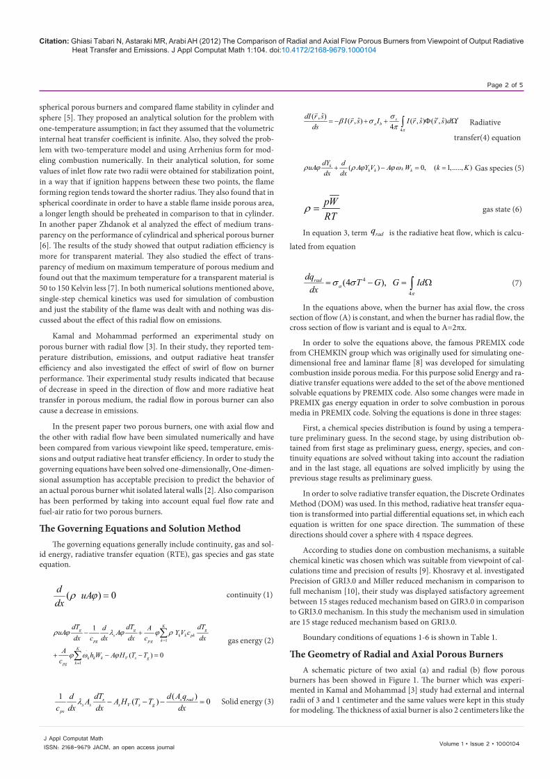
Output Radiative Heat Transfer EfficiencyOne of the other parameters dealt with in this study is the radiative
output efficiency, which is defined as equation 9.
4 4( )out s surrad
A T TFR
σεη −= (9)
The results of the study indicate that the temperature of porous burner with radial flow is lower than axial flow in both gas and solid phases. In a way that for example in stoichiometric fuel-air ratio, the temperature of solid at outlet of radial burner is 1542 and in axial burn-er is 1768 K and at first look it seems that the axial burner has more radiative heat transfer to outside environment, but in fact the radiative heat transfer to outside of burner in radial burner is more due to larger heat transfer area. In a way that this value in radial burner is 367 KW and in axial burner 211 KW, while the amount of FR for both burners is 1550 KW, therefore output radiative heat transfer efficiency in radial burner will be 23.7% and in axial burner 13.6%. Figure 9 displays radia-tive output efficiency in terms of FR for stoichiometric mixture ratio. By an increase in FR the temperature increases at outlet of the burner and as a result radiative heat transfer to outside environment increases, but it is obvious in the Figure 9 that by increase in FR, since the de-nominator of the fraction of equation 8 increases, output radiative heat transfer efficiency decreases. Bara and Ellzey also found a similar pro-cess about axial flow burner [12].
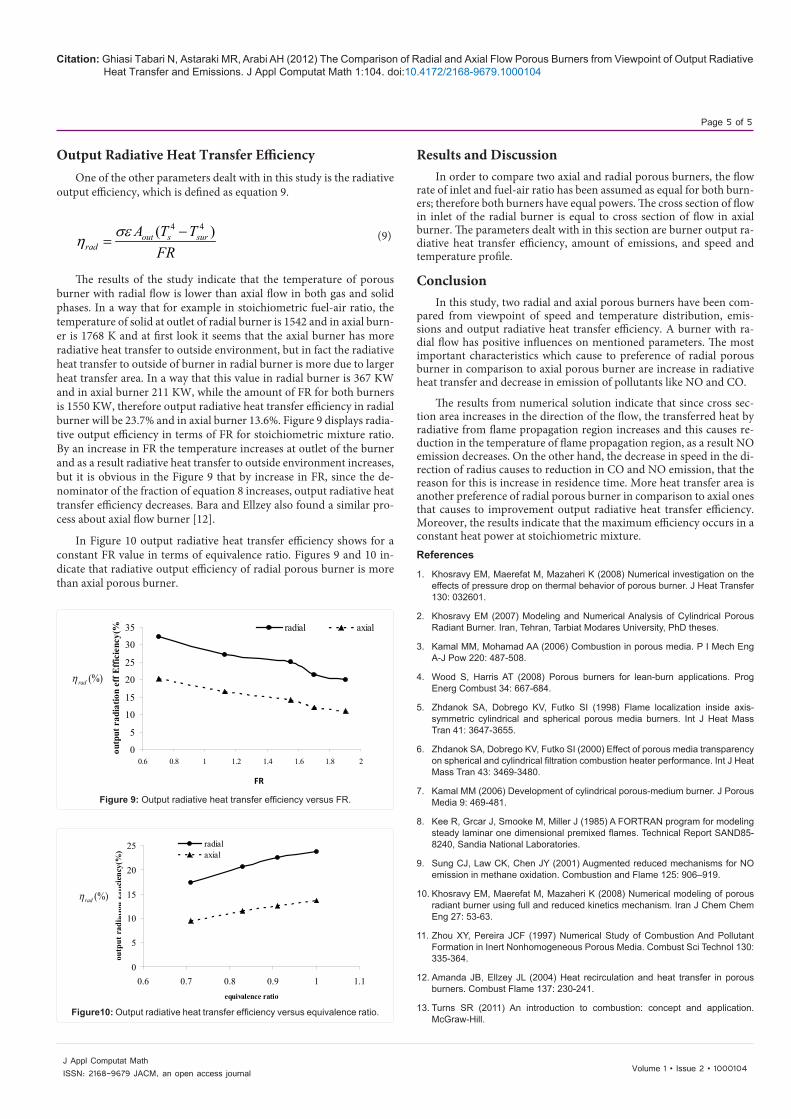
In Figure 10 output radiative heat transfer efficiency shows for a constant FR value in terms of equivalence ratio. Figures 9 and 10 in-dicate that radiative output efficiency of radial porous burner is more than axial porous burner.
Results and DiscussionIn order to compare two axial and radial porous burners, the flow
rate of inlet and fuel-air ratio has been assumed as equal for both burn-ers; therefore both burners have equal powers. The cross section of flow in inlet of the radial burner is equal to cross section of flow in axial burner. The parameters dealt with in this section are burner output ra-diative heat transfer efficiency, amount of emissions, and speed and temperature profile.
ConclusionIn this study, two radial and axial porous burners have been com-
pared from viewpoint of speed and temperature distribution, emis-sions and output radiative heat transfer efficiency. A burner with ra-dial flow has positive influences on mentioned parameters. The most important characteristics which cause to preference of radial porous burner in comparison to axial porous burner are increase in radiative heat transfer and decrease in emission of pollutants like NO and CO.
The results from numerical solution indicate that since cross sec-tion area increases in the direction of the flow, the transferred heat by radiative from flame propagation region increases and this causes re-duction in the temperature of flame propagation region, as a result NO emission decreases. On the other hand, the decrease in speed in the di-rection of radius causes to reduction in CO and NO emission, that the reason for this is increase in residence time. More heat transfer area is another preference of radial porous burner in comparison to axial ones that causes to improvement output radiative heat transfer efficiency. Moreover, the results indicate that the maximum efficiency occurs in a constant heat power at stoichiometric mixture. References
1. Khosravy EM, Maerefat M, Mazaheri K (2008) Numerical investigation on the effects of pressure drop on thermal behavior of porous burner. J Heat Transfer 130: 032601.
2. Khosravy EM (2007) Modeling and Numerical Analysis of Cylindrical Porous Radiant Burner. Iran, Tehran, Tarbiat Modares University, PhD theses.
3. Kamal MM, Mohamad AA (2006) Combustion in porous media. P I Mech Eng A-J Pow 220: 487-508.
4. Wood S, Harris AT (2008) Porous burners for lean-burn applications. Prog Energ Combust 34: 667-684.
5. Zhdanok SA, Dobrego KV, Futko SI (1998) Flame localization inside axis-symmetric cylindrical and spherical porous media burners. Int J Heat Mass Tran 41: 3647-3655.
6. Zhdanok SA, Dobrego KV, Futko SI (2000) Effect of porous media transparency on spherical and cylindrical filtration combustion heater performance. Int J Heat Mass Tran 43: 3469-3480.
7. Kamal MM (2006) Development of cylindrical porous-medium burner. J Porous Media 9: 469-481.
8. Kee R, Grcar J, Smooke M, Miller J (1985) A FORTRAN program for modeling steady laminar one dimensional premixed flames. Technical Report SAND85-8240, Sandia National Laboratories.
9. Sung CJ, Law CK, Chen JY (2001) Augmented reduced mechanisms for NO emission in methane oxidation. Combustion and Flame 125: 906–919.
10. Khosravy EM, Maerefat M, Mazaheri K (2008) Numerical modeling of porous radiant burner using full and reduced kinetics mechanism. Iran J Chem Chem Eng 27: 53-63.
11. Zhou XY, Pereira JCF (1997) Numerical Study of Combustion And Pollutant Formation in Inert Nonhomogeneous Porous Media. Combust Sci Technol 130: 335-364.
12. Amanda JB, Ellzey JL (2004) Heat recirculation and heat transfer in porous burners. Combust Flame 137: 230-241.
13. Turns SR (2011) An introduction to combustion: concept and application. McGraw-Hill.
0
5
10
15
20
25
30
35
0.6 0.8 1 1.2 1.4 1.6 1.8 2
firing rate(MJ/sec)
outp
ut r
adia
tion
eff E
ffic
ienc
y(%
)
radial axial
FR
(%)radη
Figure 9: Output radiative heat transfer efficiency versus FR.
0
5
10
15
20
25
0.6 0.7 0.8 0.9 1 1.1equivalence ratio
outp
ut r
adia
tion
Effic
ienc
y(%
)
radialaxial
(%)radη
Figure10: Output radiative heat transfer efficiency versus equivalence ratio.