Embed Size (px)
Citation preview

[ ]
Installation, Operation and MaintenanceGF90 and GF92
Doc 06EN003229
Model GF90 Insertion
Model GF92 In-Line

Notice of Proprietary RightsThis document contains confidential technical data, including trade secrets and proprietary information which is the property of Fluid ComponentsInternational LLC (FCI). Disclosure of this data to you is expressly conditioned upon your assent that its use is limited to use within your company only(and does not include manufacture or processing uses). Any other use is strictly prohibited without the prior written consent of FCI.
Visit FCI on the Worldwide Web: www.fluidcomponents.com 1755 La Costa Meadows Drive, San Marcos, California 92078 USA - 760-744-6950 - 800-854-1993 - Fax 760-736-6250
Doc. No. 06EN003229 Rev. H GF Series Flow Meter Models GF90/GF92
FLUID COMPONENTS INTERNATIONAL LLC http://www.fluidcomponents.com
Description ............................................................................................................ 1Flow Element ........................................................................................................ 1Flow Transmitter ................................................................................................... 1Technical Specifications ....................................................................................... 2
Pre-Installation ...................................................................................................... 5Flow Element Installation ...................................................................................... 5Wiring Preparation ................................................................................................ 6Wiring the Instrument ............................................................................................ 6Instrument Operation ............................................................................................. 8
Receiving/Inspection ............................................................................................. 11Packing/Shipping/Returns..................................................................................... 11Factory Calibration Note ....................................................................................... 11Pre-Installation Procedure .................................................................................... 11Install Flow Element .............................................................................................. 13Install Flow Transmitter ......................................................................................... 16Customer Wiring ................................................................................................... 20Serial Communication Option ............................................................................... 20HART Option Installation ...................................................................................... 21Foundation Field Bus ............................................................................................ 24Isolated Output Option and 4-20 mA Adjustment ................................................. 25LT81 Series Upgrade Information ......................................................................... 26Apply Power .......................................................................................................... 26
Introduction ............................................................................................................. 27Start-Up Procedure ................................................................................................. 27Operation ................................................................................................................ 27Advanced Features ................................................................................................. 41 External Input Auto-Select Procedure ................................................................... 53 Optional Veri-Cal In-Situ Calibration Verfication .................................................... 54 Optional Purge System ........................................................................................ 59 Two Point Averaging System Option ..................................................................... 60
Maintenance ........................................................................................................... 65
Introduction ............................................................................................................. 67Troubleshooting Equipment..................................................................................... 67Quick Troubleshooting ............................................................................................ 67In-Depth Troubleshooting - Standard GF90/GF92 Flow Element .............................. 68In-Depth Troubleshooting - GF90 with VeriCal Flow Element ................................... 69In-Depth Troubleshooting - The Flow Transmitter ..................................................... 71In-Depth Troubleshooting - The Installation .............................................................. 72In-Depth Troubleshooting - The Process ................................................................. 72Other Troubleshooting............................................................................................. 73Verifying Delta R's .................................................................................................. 74Repair ..................................................................................................................... 75Defective Parts ....................................................................................................... 75Customer Service ................................................................................................... 75
Appendix A. Outline Drawings and Wiring Diagrams ............................................... 77Appendix B. Glossary of Terms .............................................................................. 83Appendix C. Declaration of Conformity .................................................................... 87Appendix D. Customer Service ............................................................................... 93
1. General Information
7. Appendices
2. Quick Start Guide
3. Installation
4. Operation
5. Maintenance
6. Troubleshooting

FLUID COMPONENTS INTERNATIONAL LLC http://www.fluidcomponents.com
GF Series Flow Meter Models GF90/GF92 Doc. No. 06EN003229 Rev. H
THIS PAGE INTENTIONALLY LEFT BLANK
Doc. No. 06EN003229 Rev. H 1 GF Series Flow Meter Models GF90/GF92
FLUID COMPONENTS INTERNATIONAL LLC http://www.fluidcomponents.com
This document describes the procedures required to install, operate, maintain, and troubleshoot theModel GF90 and GF92 Flowmeters. There are a wide range of possible configurations and informationrelated to the optional features. The flowmeter is composed of a remote thermal dispersion sensingdevice (flow element) interconnected to a microprocessor-based electronics control and display package(flow transmitter). The flow element can be attached directly to the flow transmitter (local instrument)or it can be connected to the flow transmitter with a cable of up to 1000 feet or 300 meters (remoteinstrument).
The instrument is designed to operate in gaseous mass flow metering environments. The flowmeter isfactory calibrated to handle a range of flows.
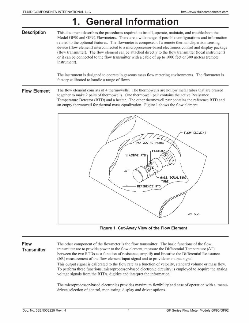
The flow element consists of 4 thermowells. The thermowells are hollow metal tubes that are braisedtogether to make 2 pairs of thermowells. One thermowell pair contains the active ResistanceTemperature Detector (RTD) and a heater. The other thermowell pair contains the reference RTD andan empty thermowell for thermal mass equalization. Figure 1 shows the flow element.
The other component of the flowmeter is the flow transmitter. The basic functions of the flowtransmitter are to provide power to the flow element, measure the Differential Temperature (∆T)between the two RTDs as a function of resistance, amplify and linearize the Differential Resistance(∆R) measurement of the flow element input signal and to provide an output signal.This output signal is calibrated to the flow rate as a function of velocity, standard volume or mass flow.To perform these functions, microprocessor-based electronic circuitry is employed to acquire the analogvoltage signals from the RTDs, digitize and interpret the information.
The microprocessor-based electronics provides maximum flexibility and ease of operation with a menu-driven selection of control, monitoring, display and driver options.
Description
1. General Information
Flow Element
FlowTransmitter
Figure 1. Cut-Away View of the Flow Element
FLUID COMPONENTS INTERNATIONAL LLC http://www.fluidcomponents.com
GF Series Flow Meter Models GF90/GF92 2 No. 06EN003229 Rev. H
TechnicalSpecifications
The flow element consists of two pairs of thermowells of the same size, shape and mass. One pair containsa platinum RTD and a heater element. The other pair contains one RTD. The RTD located next to the heaterelement is called the active RTD. The other RTD is referred to as the reference RTD. Since the active RTDis adjacent to the heater, the temperature at the walls of the thermowell are always above the temperatureof the process media. The temperature at the reference RTD is the temperature of the process media. Whenthe process media is flowing past the active RTD a quantity of heat is carried off into the flow stream. Theamount of heat taken from the active RTD is a function of the process media mass flow rate. A ∆T existsbetween the two pairs of thermowells and a proportional ∆R exists between the active and the referenceRTDs. The ∆R is measured by the flow transmitter. The relationship of ∆T to the mass flow rate iscalculated by the flow transmitter and is converted into a signal or is sent to the flow transmitter's display.
Gas Mass Flow Measurement:GF90: In ducts or pipes sizes with a minimum 2.0 inch (5.1 cm) nominal inside diameter.GF92: In pipe lines or tubing sizes from 0.125 to 3 inches (0.3175 to 7.62 centimeters).
Flow ElementsProcess Connection:GF90: 1 inch male NPT standard. Flange connections and field retractable packing gland assembliesavailable.GF92: 3/4 inch female NPT standard. 1.0, 1.5, 2.0 and 3.0 inch male or female NPT, flangeconnections available.Insertion Length — GF90: Variable length. Specify insertion “U” length (dimension from theprocess connection to the tip of the flow element) to extend the tip of the flow element 1 inch (2.5cm)past the centerline of the process pipe.Body Length — GF92: 7.25 inches (18.4cm) for 1 inch flow tubes; 12.0 inches (30.5 cm) for 1.5 to3 inch (3.81 to7.62 cm) pipe spool pieces. Variable A-lengths available.Flow Element Material: All wetted surfaces are 316 stainless steel with nickel braze. Corrosion-resistant alloys are available with factory specified all welded construction or compatible brazes.Flow Element Range:GF90: 0.25 to 1600 SFPS for most gases (ft/sec at a standard temperature of 70° F and pressure of14.7 psia) or 0.08 to 487.7 NMPS [m/sec at a normal temperature of 21.1°C andpressure of 1.013 bar (absolute)].GF92: 0.006 to 2000 SCFM for most gases (ft3/min at a standard temperature of 70°F and pressureof 14.7 psia) or 0.01 to 3398 Nm3/h [m3/ hr at a normal temperature of 21.1°C andpressure of 1.013 bar (absolute)].Actual velocity for both the GF90 and GF92 must be limited to a maximum of 200 feet per second(60.96 meters per second).Temperature Range: -50° F to +350°F (-45° C to +176.7°C) with the standard temperature flowelement. The GF90 is available in a High Temperature Flow Element configuration for servicein process temperatures from -100° F to +850° F (-73.3° C to +454.4°C).Operation Pressure: Up to 1000 psig [68.9 bar (gauge)].
TransmitterSignal Output:Analog: Two independent signal outputs available that may be field set from the following listedselection:4-20 mA, 600 ohms maximum load0-10 Vdc, 5000 ohms minimum load0-5 Vdc, 2500 ohms minimum load1-5 Vdc, 2500 ohms minimum loadDigital: RS-232C (EIA-232) serial port.Switch Points (Dual Alarms): The switch points may be field set by programming the GF90 orGF92 to alarm at high, low or windowed flow or at high, low or windowed process temperature.
Doc. No. 06EN003229 Rev. H 3 GF Series Flow Meter Models GF90/GF92
FLUID COMPONENTS INTERNATIONAL LLC http://www.fluidcomponents.com
Relays: Two Relays independently adjustable: 2 amps bifurcated gold plated DPDT contacts, 0-2.0amps at 28 Vdc or 115 Vac resistive, 0.1 volts at 230 Vac resistive. 0 amps (or Dry) rating is good if loadis kept below 30mA.Slave Relay Energization Terminals: Customer provided relay may be energized at programmablevalues connecting to points on the output terminal strip.+Ext Relay: 20 Vdc, sourcing up to 100 mA total both relay outputs.-Ext Relay: Open/Ground (switching).Power Input: 115 Vac, ±15 Vac, 16 watts maximum or 230 Vac, ±30 Vac, 50/60Hz, 16 wattsmaximum; or 24 Vdc, -2 and +6 Vdc, 16 watts maximum as selected by the power input switch andterminal selection.Indicator Display & Built-In Keypad: 4 lines by 20 character liquid crystal display that may beprogrammed to indicate flow rate, total flow, temperature, and switch point status in customerdetermined English or Metric (SI) values. Keypad permits easy touch programming to change zero,span, switch points, and units of measurement and for instrument verification, trouble shooting andother critical instrument functions.
Electrical EnclosuresFiberglass NEMA/CSA Type 4X is standard. All aluminum and stainless steel enclosures are rated forhazardous location use (Class I and II, Division 1 and 2, Groups B, C, D, E, F and G; and EEx d IIC)and resists the effect of weather and corrosion (NEMA/CSA Type 4X and equivalent to IP66).Electrical Connection: 1 inch female NPT.Temperature Range: 0°F to +150°F (-18°C to +65.6°C).
FlowAccuracy: ±1% reading + 0.5% full scale.Repeatability: ±0.5% reading or better.Turndown Ratio: Field set to within specified flow range from 2:1 to 1000:1. Turndown ratios up to1000:1 are possible in some applications. Signal output may be field set to be zero or non-zero based.Up to three independent calibrations may be stored in the GF Series transmitter and selected via thebuilt-in keypad, RS-232C Serial Port or Auxiliary Input Terminal (4-20 mA).Calibration Adjustment: Up to three independent calibration groups are available. Each group isprecisely calibrated at the factory in accordance with the submitted Application Data Sheet toturndown ratios as high as 1000:1. Most calibrations are performed in the actual process fluid andprocess conditions described by the customer’s specification. Adjustment to zero and span are madeeasily in the field by using the keypad to input revised flow or temperature range information.
TemperatureAccuracy: ±2°F (±1.1°C ). Valid only above minimum flowing conditions of 5 SFPS (1.5 NMPS).Repeatability: ±1°F (±0.55°C).
System ApprovalsFactory Mutual Research (FM), CSA, CE Mark, CENELEC, CRN and ATEX.
TechnicalSpecifications(Cont’d)

FLUID COMPONENTS INTERNATIONAL LLC http://www.fluidcomponents.com
GF Series Flow Meter Models GF90/GF92 4 No. 06EN003229 Rev. H
THIS PAGE INTENTIONALLY LEFT BLANK

Doc. No. 06EN003229 Rev. H 5 GF Series Flow Meter Models GF90/GF92
FLUID COMPONENTS INTERNATIONAL LLC http://www.fluidcomponents.com
To get the best results from the instrument, the sensor should be located 20 pipe diameters downstream from any flow disturbance (valve, pipe elbow, etc.) and 10 pipe diameters upstream fromany disturbance.
The outside of the instrument has tags which show the model number, tag number (if noted on thecustomer’s order) and serial number along with other important safety information. Compare thisinformation with the appropriate pipe installation drawings and calibration sheets to verify theinstrument is the correct configuration.
Pre-Installation
2. Quick Start Guide
The recommended installation/troubleshooting tools are:
1 ea. Open-ended wrench to fit the NPT connection1 ea. Open-ended wrench to fit the flanged fitting nuts and bolts1 ea. Small flat blade screw driver for manipulating potentiometers1 ea. Medium flat blade screwdriver for tightening connections1 ea. Medium phillips head screwdriver for tightening connections1 ea. 3 mm Allen wrench1 ea. Measuring tape for proper flow element placement1 ea. DVM for Ohm/Voltage measurements
Verify that the serial numbers on the enclosure(s) tag(s), flow element and electronics match. Theinstrument may not work if the serial numbers are miss-matched.
Install the flow element, with the flow arrow pointing in the direction of media flow. The elementshould be in the center line of the process pipe or rectangular duct as shown above.
If the NPT option is used, see Page 13 for installation instructions.
If the flanged option is used, see Page 13 for installation instructions.
If the GF92 in-line option is used, see Page 14 for installation instructions.
NOTE: ST98 type flow element only inserts 0.50 inches past centerline. See VeriCal SystemDiagram on page 54.
Flow ElementInstallation
Example of GF90 Flow Meter (See Appendix A for Specific Diagrams)
FLUID COMPONENTS INTERNATIONAL LLC http://www.fluidcomponents.com
GF Series Flow Meter Models GF90/GF92 6 Doc. No. 06EN003229 Rev. H
Before the instrument is opened to install the wiring, FCI recommends that ESD precautions beobserved. See Page 11 for ESD instructions.
WiringPreparation
This section wires the transmitter inputs, outputs and interconnection cabling for the instrument.Route the output wiring through the opposite port from the power wiring. The maximum gauge ofwire to use is 16 AWG. See Table 1 on Page 16 and Table 2 on Page 17 for the maximumdistance that wires can be run.
Only qualified personnel are to wire or test this instrument. The operator assumesall responsibilities for safe practices while wiring or troubleshooting.
CAUTION:
ALERT: The instrument contains electrostatic discharge (ESD) sensitive devices. Use standardESD precautions when handling the flow transmitter.
Wiring theInstrument
Wiring the Flow Element
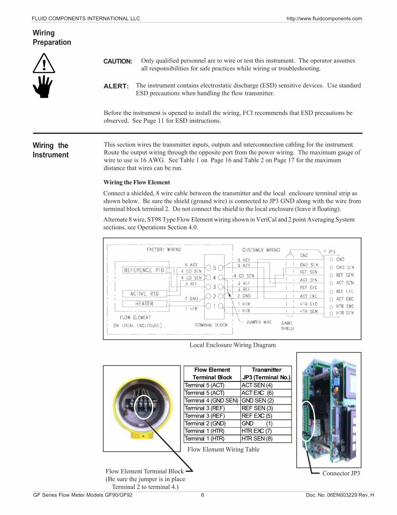
Connect a shielded, 8 wire cable between the transmitter and the local enclosure terminal strip asshown below. Be sure the shield (ground wire) is connected to JP3 GND along with the wire fromterminal block terminal 2. Do not connect the shield to the local enclosure (leave it floating).Alternate 8 wire, ST98 Type Flow Element wiring shown in VeriCal and 2 point Averaging Systemsections, see Operations Section 4.0.
Flow Element Terminal Block(Be sure the jumper is in place Terminal 2 to terminal 4.)
Local Enclosure Wiring Diagram
Flow Element Wiring Table
Flow Element TransmitterTerminal Block JP3 (Terminal No.)
Terminal 5 (ACT) ACT SEN (4)Terminal 5 (ACT) ACT EXC (6)Terminal 4 (GND SEN) GND SEN (2)Terminal 3 (REF) REF SEN (3)Terminal 3 (REF) REF EXC (5)Terminal 2 (GND) GND (1)Terminal 1 (HTR) HTR EXC (7)Terminal 1 (HTR) HTR SEN (8)
Connector JP3

Doc. No. 06EN003229 Rev. H 7 GF Series Flow Meter Models GF90/GF92
FLUID COMPONENTS INTERNATIONAL LLC http://www.fluidcomponents.com
Analog Output 2 is connected in a similar manor as Analog Output 1. ( For Voltage Output:0 - 5, 0 - 10 or 1 -5 Vdc; connect a positive wire to + E OUT2 and a negative wire toOUT 2 COM. For Current Output: 4 - 20 mA; connect a positive wire to + I OUT2 and anegative wire to OUT 2 COM.)
For Voltage Output: 0 - 5, 0 - 10 or 1 -5 Vdc; connect a positive wire to + E OUTand a negative wire to OUT COM.
Analog OutputPlug Location
Wiring the Instrument’s Signal Output to the Customer Application:
Alert: Either voltage or current from the Analog Outputs can be connected to the customerapplication, not both. (Example: Voltage and current from analog output 1 cannot beconnected.) However, one Analog Output can be wired for current and the otherAnalog Output can be wired for Voltage.
Customer Connections Analog Output Diagram
For Current Output: 4 - 20 mA; connect a positive wire to + I OUT and a negative wireto OUT COM.
Wiring the Output Relays:
The instrument contains two sets of alarm output relays (connectors JP4 Relay Output 1, and JP5Relay Output 2). They can be wired by the customer. (NO = Normally Open, NC = NormallyClosed, Pole = Common)
Output Relay Wiring Diagram Connectors JP5 and JP4
FLUID COMPONENTS INTERNATIONAL LLC http://www.fluidcomponents.com
GF Series Flow Meter Models GF90/GF92 8 Doc. No. 06EN003229 Rev. H
The instrument has been configured and calibrated to custom specifications. In-depth programmingof the instrument in the field should not be necessary.
Apply power to the instrument. Wait 10 minutes for the instrument to stabilize. During this periodthe instrument may indicate a high flow condition. When the instrument is powered up, theinstrument will display an initialization sequence. Then the instrument will display the normaloperation information. Shown below is the normal operation window.
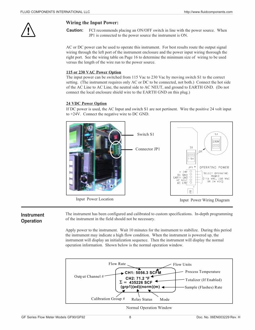
Caution: FCI recommends placing an ON/OFF switch in line with the power source. WhenJP1 is connected to the power source the instrument is ON.
Wiring the Input Power:
Switch S1
Connector JP1
Input Power Location Input Power Wiring Diagram
Normal Operation Window
AC or DC power can be used to operate this instrument. For best results route the output signalwiring through the left port of the instrument enclosure and the power input wiring thorough theright port. See the wiring table on Page 16 to determine the minimum size of wiring to be usedversus the length of the wire run to the power source.
115 or 230 VAC Power OptionThe input power can be switched from 115 Vac to 230 Vac by moving switch S1 to the correctsetting. (The instrument requires only AC or DC to be connected, not both.) Connect the hot sideof the AC Line to AC Line, the neutral side to AC NEUT, and ground to EARTH GND. (Do notconnect the local enclosure shield wire to the EARTH GND on this plug.)
24 VDC Power OptionIf DC power is used, the AC Input and switch S1 are not pertinent. Wire the positive 24 volt inputto +24V. Connect the negative wire to DC GND.
CH1: 5056.3 SCFMCH2: 71.2 °F
435226 SCF(grp1)(ed)(norm)(m)
Output Channel #
Flow Rate
Process Temperature
Sample (Flashes) RateΣ =
ModeRelay StatusCalibration Group #
Totalizer (If Enabled)
Flow Units
InstrumentOperation
Doc. No. 06EN003229 Rev. H 9 GF Series Flow Meter Models GF90/GF92
FLUID COMPONENTS INTERNATIONAL LLC http://www.fluidcomponents.com
0.0 MAIN MENU1 = Normal Operation2 = Port Setup3 = Display Setup4 = Miscellaneous
2.0 PORT SETUP1 = Analog Output2 = Relays3 = Comm Output4 = Aux Input
3.0 DISPLAY SETUP1 = Flow Setup2 = Temperature Setup3 = Totalizer Setup4 = Sample Rate
4.0 MISCELLANEOUS1 = Set Group2 = Corrector Setup3 = Password Setup
CH1: 5056.3 SCFMCH2: 71.2 FΣ = 435226 SCF(grp1) (dd) (mode N) (m)
Normal Operation
QUICKOPERATION
MENU
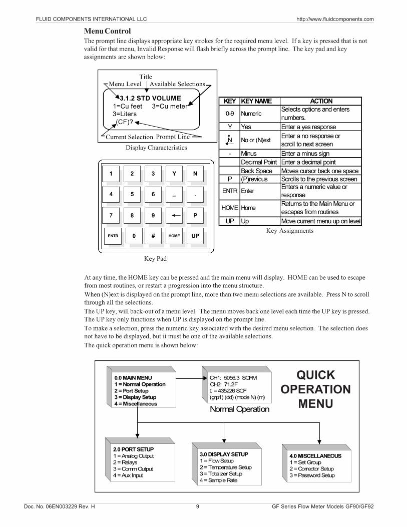
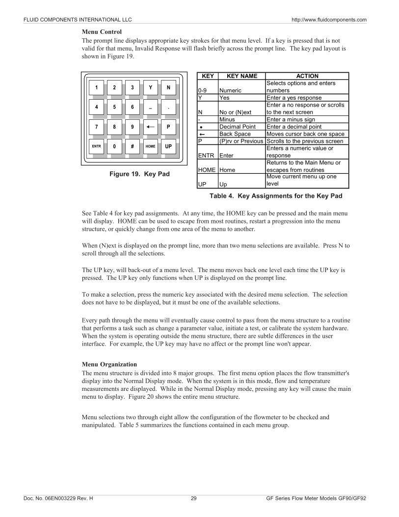
Menu ControlThe prompt line displays appropriate key strokes for the required menu level. If a key is pressed that is notvalid for that menu, Invalid Response will flash briefly across the prompt line. The key pad and keyassignments are shown below:
•
At any time, the HOME key can be pressed and the main menu will display. HOME can be used to escapefrom most routines, or restart a progression into the menu structure.When (N)ext is displayed on the prompt line, more than two menu selections are available. Press N to scrollthrough all the selections.The UP key, will back-out of a menu level. The menu moves back one level each time the UP key is pressed.The UP key only functions when UP is displayed on the prompt line.To make a selection, press the numeric key associated with the desired menu selection. The selection doesnot have to be displayed, but it must be one of the available selections.The quick operation menu is shown below:
Key Assignments
3.1.2 STD VOLUME1=Cu feet3=Liters(CF)?
Menu LevelTitle
Available Selections
Prompt Line
3=Cu meter
Current SelectionDisplay Characteristics
Key Pad
1 2 3 Y N
4 5 6 _ .
7 8 9 P
ENTR 0 # HOME UP
KEY KEY NAME ACTION
0-9 Numeric Selects options and enters numbers.
Y Yes Enter a yes response
N No or (N)ext Enter a no response or scroll to next screen
- Minus Enter a minus signDecimal Point Enter a decimal pointBack Space Moves cursor back one space
P (P)revious Scrolls to the previous screen
ENTR Enter Enters a numeric value or response
HOME Home Returns to the Main Menu or escapes from routines
UP Up Move current menu up on level

FLUID COMPONENTS INTERNATIONAL LLC http://www.fluidcomponents.com
GF Series Flow Meter Models GF90/GF92 10 Doc. No. 06EN003229 Rev. H
THIS PAGE INTENTIONALLY LEFT BLANK
Doc. No. 06EN003229 Rev. H 11 GF Series Flowmeter Models GF90/GF92
FLUID COMPONENTS INTERNATIONAL LLC http://www.fluidcomponents.com
• Unpack carefully.• Verify that all items in the packing list are received and are correct.• Inspect all instruments for damage or contaminants prior to installation.If the above three items are satisfactory, proceed with the installation. If not, then stop and contact acustomer service representative.
These issues are addressed in Appendix D - Customer Service.
The instrument is factory calibrated to the flow range specified in the order. There is no need toperform any verification or calibration steps prior to installing and placing the instrument in service.
CAUTION: Only qualified personnel should install this instrument. Install and follow safetyprocedures in accordance with the current National Electrical Code. Ensure that poweris off during installation. Any instances where power is applied to the instrument will benoted in this manual. Where the instructions call for the use of electrical current, theoperator assumes all responsibility for conformance to safety standards and practices.
ALERT: The instrument is not designed for weld-in-place applications. Never weld to processconnection or a structural support.
Damage resulting from moisture penetration of the enclosure(s) is not covered byproduct warranty.
The flow transmitter contains electrostatic discharge (ESD) sensitive devices. Usestandard ESD precautions when handling the circuit board assemblies. See below forESD details.
Use Standard ESD PrecautionsWhen opening an instrument enclosure or handling the flow transmitter use standard ESD precautions.FCI recommends the use of the following precautions: Use a wrist band or heel strap with a1 megohm resistor connected to ground. If the instrument is in a shop setting there should be staticconductive mats on the work table and floor with a 1 megohm resistor connected to ground. Connectthe instrument to ground. Apply antistatic agents to hand tools to be used on the instrument. Keep highstatic producing items away from the instrument such as non-ESD approved plastic, tape and packingfoam.The above precautions are minimum requirements to be used. The complete use of ESD precautionscan be found in the U.S. Department of Defense Handbook 263.
3. Installation
Prepare or Verify the Flow Element LocationPrepare the process pipe for installation or inspect the already prepared location to ensure that theinstrument will fit into the system.Mount the flow element at least 20 diameters downstream and 10 diameters upstream from any bendsor interference in the process pipe or duct to achieve the greatest accuracy.
Receiving/Inspection
Packing/Shipping/Returns
Pre-InstallationProcedure
FactoryCalibrationNote
FLUID COMPONENTS INTERNATIONAL LLC http://www.fluidcomponents.com
GF Series Flowmeter Models GF90/GF92 12 Doc. No. 06EN003229 Rev. H
Verify DimensionsThe GF90 Insertion Models have an adjustable insertion length ferrule until it is locked into position.Verify all dimensions before locking the fitting in place. See the appropriate figures in Appendix A.
NOTE: Two types of ferrules are available. One type of ferrule is made from Teflon. This can betightened and loosened repeatedly at different places on the flow element. The other type of ferrule ismade from Stainless Steel. This ferrule can only be tightened in one place on the flow element. TheStainless Steel Ferrule makes an indentation into the flow element for a more firm fit.
The GF92 In-Line Model's flow element has a tube or pipe length and diameter that is specified at thetime of order. This dimension should be double checked with the process line.
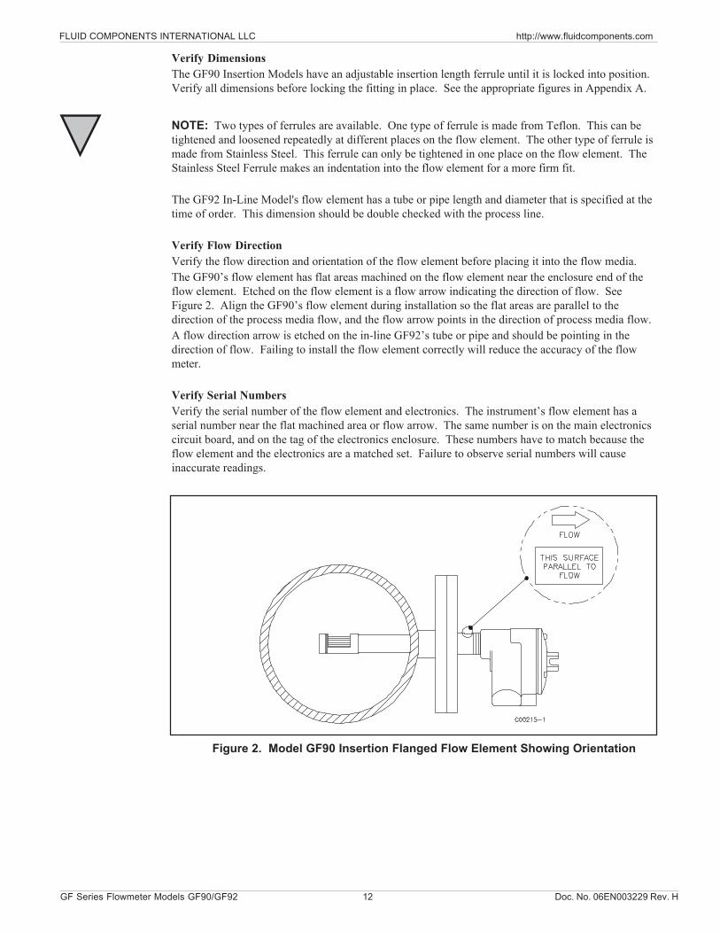
Verify Flow DirectionVerify the flow direction and orientation of the flow element before placing it into the flow media.The GF90’s flow element has flat areas machined on the flow element near the enclosure end of theflow element. Etched on the flow element is a flow arrow indicating the direction of flow. SeeFigure 2. Align the GF90’s flow element during installation so the flat areas are parallel to thedirection of the process media flow, and the flow arrow points in the direction of process media flow.A flow direction arrow is etched on the in-line GF92’s tube or pipe and should be pointing in thedirection of flow. Failing to install the flow element correctly will reduce the accuracy of the flowmeter.
Verify Serial NumbersVerify the serial number of the flow element and electronics. The instrument’s flow element has aserial number near the flat machined area or flow arrow. The same number is on the main electronicscircuit board, and on the tag of the electronics enclosure. These numbers have to match because theflow element and the electronics are a matched set. Failure to observe serial numbers will causeinaccurate readings.
Figure 2. Model GF90 Insertion Flanged Flow Element Showing Orientation
Doc. No. 06EN003229 Rev. H 13 GF Series Flowmeter Models GF90/GF92
FLUID COMPONENTS INTERNATIONAL LLC http://www.fluidcomponents.com
Install FlowElement
ALERT: Do not overtighten the flow element. The RTD's can be damaged if the flow element isforced into the far wall of the pipe or vessel.Cable Glands and Conduit FittingsAll cable glands and conduit fittings, including conduit plugs, must meet or exceed the areaapproval where unit is being installed.
NOTE: The instrument accuracy will be reduced if the media flow is reversed from the flowdirection of the flow arrow machined on the flow element or if the flats are not parallel,within ±1° of the flow direction.
Select one of the following installation procedures which is applicable to the unit being installed.
GF90 Flange MountThe flange mount flow element is shown in Figure 2. Attach the process mating flange with care. Thecorrect orientation of the flow element must be maintained to ensure the calibrated accuracy.• Verify that the process media flow is in the same direction as the arrow on the FLAT.• Apply the appropriate gasket and/or sealant to flange mount as required.• Mate flow element flange to process mount keeping flat oriented properly.• Attach with bolt, two flat washers, lock washer and nut for each bolt hole, apply lubricant/sealant
to male threads and torque. Refer to ANISI B16.5 specifications.
GF90 NPT Pipe Thread Mount
ALERT: DO NOT change the orientation of the flow element in the enclosure as theinterconnecting RTD and heater wiring could be stressed and damaged. DO NOT applyany torque to the flow element enclosure - only apply to NPT pipe surface itself.
NOTE: When mounting the flow element to the process pipe, it is important that a lubricant/sealant is applied to the male threads of all connections. A lubricant/sealant compatiblewith the process environment should be used. All connections should be tightened firmly.To avoid leaks do not overtighten or cross-thread connections.
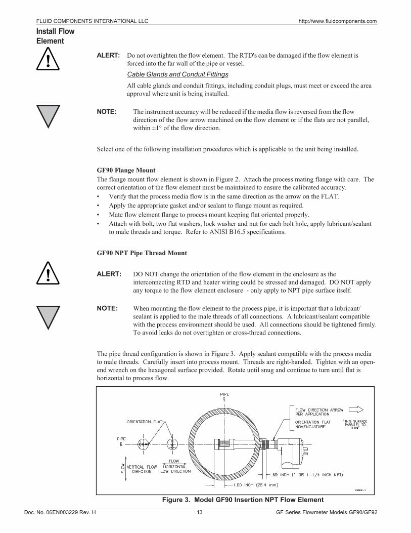
The pipe thread configuration is shown in Figure 3. Apply sealant compatible with the process mediato male threads. Carefully insert into process mount. Threads are right-handed. Tighten with an open-end wrench on the hexagonal surface provided. Rotate until snug and continue to turn until flat ishorizontal to process flow.
Figure 3. Model GF90 Insertion NPT Flow Element
FLUID COMPONENTS INTERNATIONAL LLC http://www.fluidcomponents.com
GF Series Flowmeter Models GF90/GF92 14 Doc. No. 06EN003229 Rev. H
GF90 Adjustable / Retractable Flow Element AssemblyApplications involving the use of a packing gland (low, medium or high pressure) should refer tothe drawings located in Appendix A for additional detail.• NPT and flange packing gland mounts are available. The valve assembly with appropriate
connections are customer supplied. Follow the pipe thread procedure or the flange procedureas shown on the previous page.
• Then tighten packing nut until internal packing is tight enough so that the friction fit on theshaft is adequate to prevent leakage but not prevent the shaft from sliding. Position the flathorizontal with arrow in direction of process flow.
• Proceed to insert the flow element into process media line. For the medium pressure packinggland use the adjusting nuts on the all-thread to pull the flow element into properpredetermined depth position.
• Tighten the opposing lock nuts on the all-threads. Tighten the packing nut another 1/2 to1 turn until tight (approximately 65 to 85 ft-lbs torque).
• Rotate split ring locking collar to line up with connecting strap welded to packing nut.Tighten the two 1/4-28 hex socket cap screws on the split ring locking collar. Open valve -check for process media leakage.
• Reverse these steps for removal.
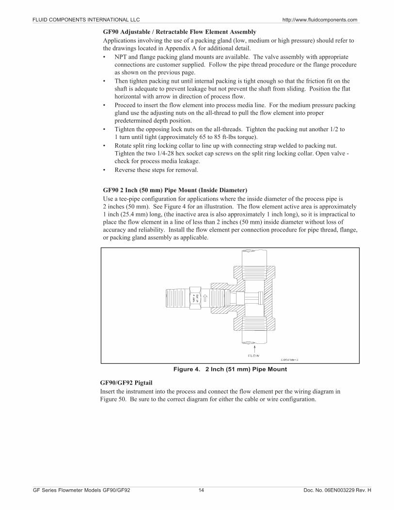
GF90 2 Inch (50 mm) Pipe Mount (Inside Diameter)Use a tee-pipe configuration for applications where the inside diameter of the process pipe is2 inches (50 mm). See Figure 4 for an illustration. The flow element active area is approximately1 inch (25.4 mm) long, (the inactive area is also approximately 1 inch long), so it is impractical toplace the flow element in a line of less than 2 inches (50 mm) inside diameter without loss ofaccuracy and reliability. Install the flow element per connection procedure for pipe thread, flange,or packing gland assembly as applicable.
Figure 4. 2 Inch (51 mm) Pipe Mount
GF90/GF92 PigtailInsert the instrument into the process and connect the flow element per the wiring diagram inFigure 50. Be sure to the correct diagram for either the cable or wire configuration.
Doc. No. 06EN003229 Rev. H 15 GF Series Flowmeter Models GF90/GF92
FLUID COMPONENTS INTERNATIONAL LLC http://www.fluidcomponents.com
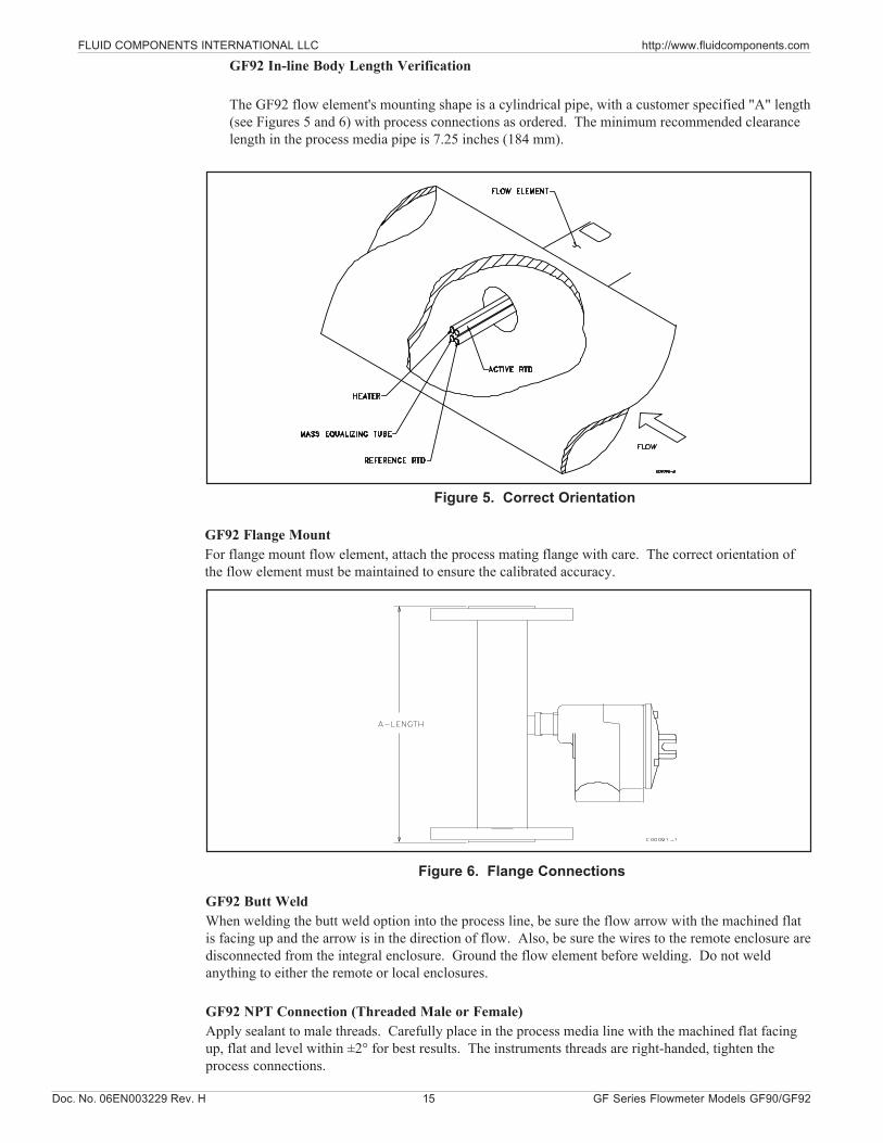
GF92 In-line Body Length Verification
The GF92 flow element's mounting shape is a cylindrical pipe, with a customer specified "A" length(see Figures 5 and 6) with process connections as ordered. The minimum recommended clearancelength in the process media pipe is 7.25 inches (184 mm).
Figure 5. Correct Orientation
Figure 6. Flange Connections
GF92 Butt WeldWhen welding the butt weld option into the process line, be sure the flow arrow with the machined flatis facing up and the arrow is in the direction of flow. Also, be sure the wires to the remote enclosure aredisconnected from the integral enclosure. Ground the flow element before welding. Do not weldanything to either the remote or local enclosures.
GF92 NPT Connection (Threaded Male or Female)Apply sealant to male threads. Carefully place in the process media line with the machined flat facingup, flat and level within ±2° for best results. The instruments threads are right-handed, tighten theprocess connections.
GF92 Flange MountFor flange mount flow element, attach the process mating flange with care. The correct orientation ofthe flow element must be maintained to ensure the calibrated accuracy.

FLUID COMPONENTS INTERNATIONAL LLC http://www.fluidcomponents.com
GF Series Flowmeter Models GF90/GF92 16 Doc. No. 06EN003229 Rev. H
CAUTION: Ensure that all power is off before wiring any circuit.
ALERT: In applications where the flow element is located in an explosive environment, isolatethe conduit before it leaves the environment. A potting Y may be used to provide theisolation.
Cable Glands and Conduit FittingsAll cable glands and conduit fittings, including conduit plugs, must meet or exceed thearea approval where unit is being installed.
NOTE: FCI recommends installing an input power disconnect switch and fuse near the flowtransmitter to interrupt power during installation, maintenance, calibration, andtroubleshooting procedures.
Make all electrical connections through the 3/4 inch NPT ports in the enclosure. Run all electricalcables through appropriate conduit or protective sheathing.
Minimum Wire SizeIf the instrument is used in a remote configuration, a shielded, 8 conductor cable is to be used betweenthe local and remote enclosures. Table 1 shows the smallest (maximum AWG number) copper wirethat should be used in the cable and in other wiring. Use a lower gauge of wire (larger diameter) forless of a voltage drop. Contact FCI concerning greater distances than those listed in the table. Thesensing element cable for the remote option must be shielded. The maximum wire size of the non-power connectors in the instrument is 16 AWG (1.47 mm). The maximum wire size of the powerconnectors in the instrument is 12 AWG (2.36 mm). Table 2 shows the AWG to millimeterconversions.
Table 1. Maximum AWG Number
Install FlowTransmitter
Remote Hardware Location (GF90 and GF92)The outline dimensions shown in Appendix A show the physical dimensions for the proper mountingof the flow element and transmitter electronics enclosure. Select a location for the flow transmitterwithin 1000 feet (310 M) of the flow element. Pigtail flow elements can not be located more than10 feet (3 M) from the flow transmitter. This location should be easily accessible with enough room tounscrew the enclosure top at any time. Secure the enclosure to a surface capable of providing support.Use appropriate hardware to secure the enclosure.
* Requires a an 8 conductor shielded cable. The shield is connected to the GND pin of JP3 of theflow transmitter. The other end of the shield is left floating (no connection to the terminal block).
10 FT. (3M)
50 FT. (15 M)
100 FT. (31 M)
250 FT. (76 M)
500 FT. (152 M)
1000 FT. (305 M)
Power 22 22 22 20 18 16Relay (2A at 220 VAC)
24 22 20 16 12 N/R
Relay (10A at 120 VAC or 24 VDC)
22 16 12
Flow Element W ires* 24 24 24 22 22 18
ConnectionMaximum Distance for AW G
Not Recommended
Doc. No. 06EN003229 Rev. H 17 GF Series Flowmeter Models GF90/GF92
FLUID COMPONENTS INTERNATIONAL LLC http://www.fluidcomponents.com
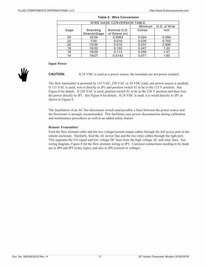
W IRE GAGE CONVERSION TABLE Minimum O.D. of W ire
Gage Stranding Strands/Gage
Nominal O.D. of Strand (in)
Inches mm
24 10/34 0.0063 0.024 0.584 22 7/30 0.010 0.030 0.762 20 10/30 0.010 0.037 0.890 18 16/30 0.100 0.047 1.20 16 19/29 0.113 0.058 1.47 14 19/27 0.0142 0.071 1.85
Table 2. Wire Conversion
Input Power
CAUTION: If 24 VDC is used as a power source, the terminals are not power isolated.
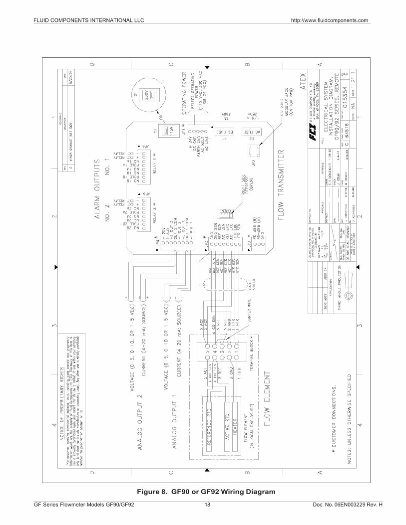
The flow transmitter is powered by 115 VAC, 230 VAC or 24 VDC (only one power source is needed).If 115 VAC is used, wire it directly to JP1 and position switch S1 to be in the 115 V position. SeeFigure 8 for details. If 230 VAC is used, position switch S1 to be in the 230 V position and then wirethe power directly to JP1. See Figure 8 for details. If 24 VDC is used, it is wired directly to JP1 asshown in Figure 8.
The installation of an AC line disconnect switch (and possibly a fuse) between the power source andthe flowmeter is strongly recommended. This facilitates easy power disconnection during calibrationand maintenance procedures as well as an added safety feature.
Remote TransmitterFeed the flow element cable and the two voltage/current output cables through the left access port in theremote enclosure. Similarly, feed the AC power line and the two relay cables through the right port.This separates the I/O signal and low voltage DC lines from the high voltage AC and relay lines. Seewiring diagram, Figure 8 for the flow element wiring to JP3. Customer connections needing to be madeare to JP4 and JP5 (relay logic), and also to JP6 (current or voltage).
FLUID COMPONENTS INTERNATIONAL LLC http://www.fluidcomponents.com
GF Series Flowmeter Models GF90/GF92 18 Doc. No. 06EN003229 Rev. H
Figure 8. GF90 or GF92 Wiring Diagram
Doc. No. 06EN003229 Rev. H 19 GF Series Flowmeter Models GF90/GF92
FLUID COMPONENTS INTERNATIONAL LLC http://www.fluidcomponents.com
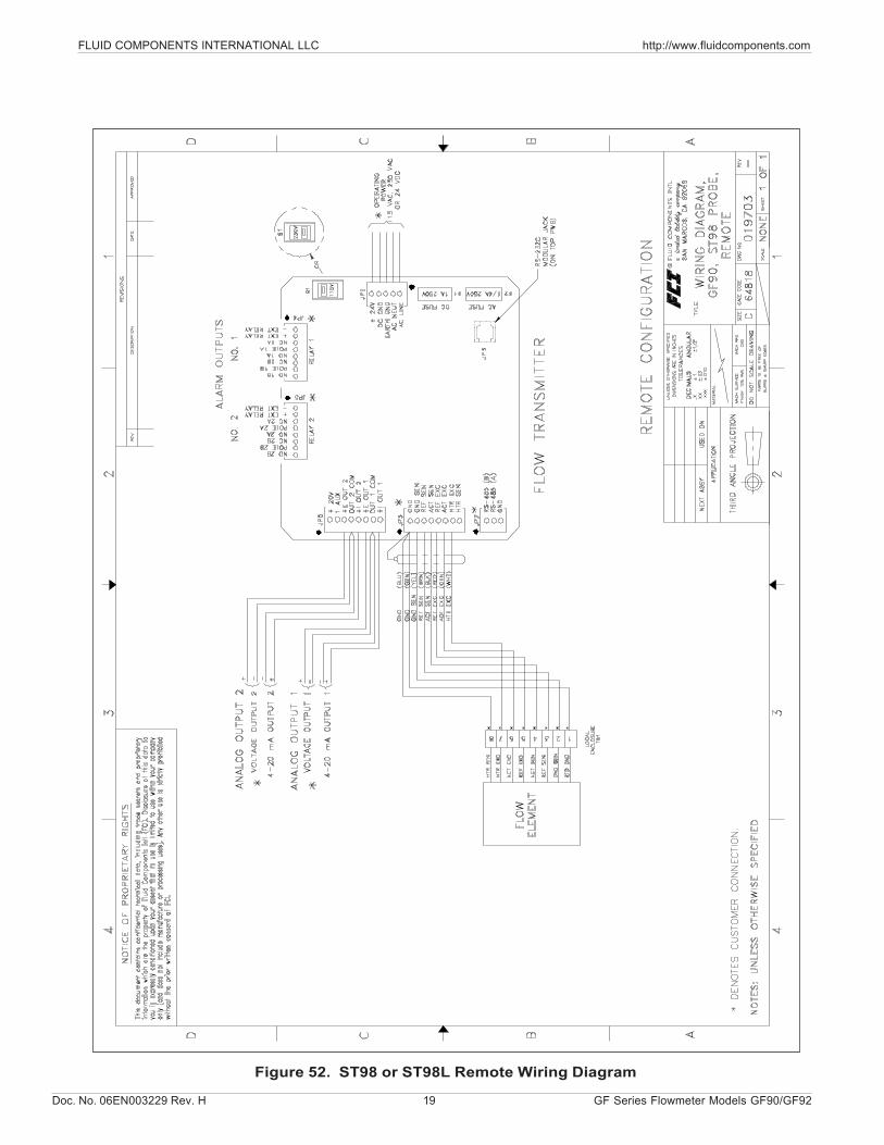
Figure 52. ST98 or ST98L Remote Wiring Diagram
FLUID COMPONENTS INTERNATIONAL LLC http://www.fluidcomponents.com
GF Series Flowmeter Models GF90/GF92 20 Doc. No. 06EN003229 Rev. H
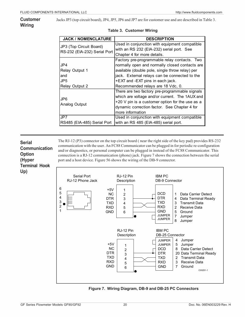
The RJ-12 (P3) connector on the top circuit board ( near the right side of the key pad) provides RS-232communication with the user. An FC88 Communicator can be plugged in for periodic re-configurationand/or diagnostics, or personal computer can be plugged in instead of the FC88 Communicator. Thisconnection is a RJ-12 communication (phone) jack. Figure 7 shows the connection between the serialport and a host device. Figure 56 shows the wiring of the DB-9 connector.
654321
Serial PortRJ-12 Phone Jack
123456
RJ-12 PinDescription
DCDDTRTXDRXDGNDJUMPERJUMPER
IBM PCDB-9 Connector
Data Carrier DetectData Terminal ReadyTransmit DataReceive DataGroundJumperJumper
+5VNC
DTRTXDRXDGND
123456
RJ-12 PinDescription
JUMPERJUMPERDCDDTRTXDRXDGND
IBM PCDB-25 Connector
JumperJumperData Carrier DetectData Terminal ReadyTransmit DataReceive DataGround
+5VNC
DTRTXDRXDGND
45820237
1432578
C00251-1
SerialCommunicationOption(HyperTerminal HookUp)
JACK / NOMENCLATURE DESCRIPTION
JP3 (Top Circuit Board) RS-232 (EIA-232) Serial Port
Used in conjunction with equipment compatible with an RS 232 (EIA-232) serial port. See Chapter 4 for more details.
JP4 Relay Output 1 and JP5 Relay Output 2
Factory pre-programmable relay contacts. Two normally open and normally closed contacts are available (double pole, single throw relay) per jack. External relays can be connected to the +EXT and -EXT pins in each jack. Recommended relays are 18 Vdc, 0.
JP6 Analog Output
There are two factory pre-programmable signals which are voltage and/or current. The 1AUX and +20 V pin is a customer option for the use as a dynamic correction factor. See Chapter 4 for more information
JP7 RS485 (EIA-485) Serial Port
Used in conjunction with equipment compatible with an RS 485 (EIA-485) serial port.
CustomerWiring
Figure 7. Wiring Diagram, DB-9 and DB-25 PC Connectors
Jacks JP3 (top circuit board), JP4, JP5, JP6 and JP7 are for customer use and are described in Table 3.
Table 3. Customer Wiring
Doc. No. 06EN003229 Rev. H 21 GF Series Flowmeter Models GF90/GF92
FLUID COMPONENTS INTERNATIONAL LLC http://www.fluidcomponents.com
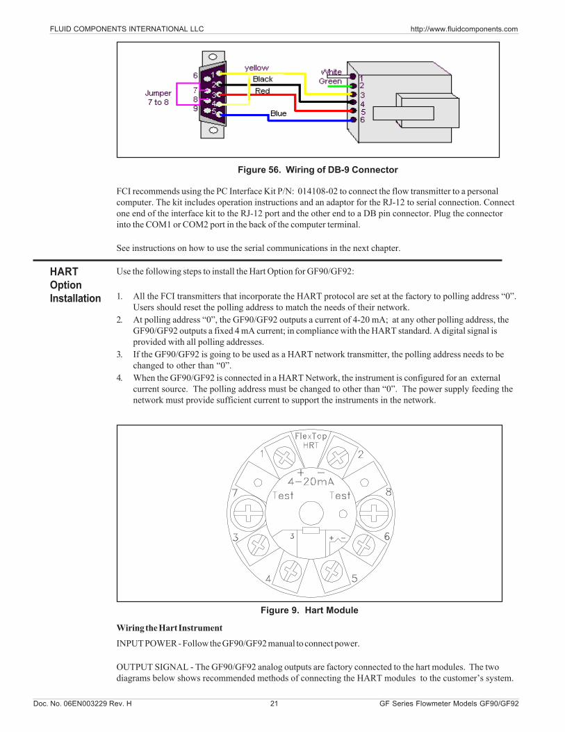
Use the following steps to install the Hart Option for GF90/GF92:
1. All the FCI transmitters that incorporate the HART protocol are set at the factory to polling address “0”.Users should reset the polling address to match the needs of their network.
2. At polling address “0”, the GF90/GF92 outputs a current of 4-20 mA; at any other polling address, theGF90/GF92 outputs a fixed 4 mA current; in compliance with the HART standard. A digital signal isprovided with all polling addresses.
3. If the GF90/GF92 is going to be used as a HART network transmitter, the polling address needs to bechanged to other than “0”.
4. When the GF90/GF92 is connected in a HART Network, the instrument is configured for an externalcurrent source. The polling address must be changed to other than “0”. The power supply feeding thenetwork must provide sufficient current to support the instruments in the network.
Figure 9. Hart Module
Wiring the Hart Instrument
INPUT POWER - Follow the GF90/GF92 manual to connect power.
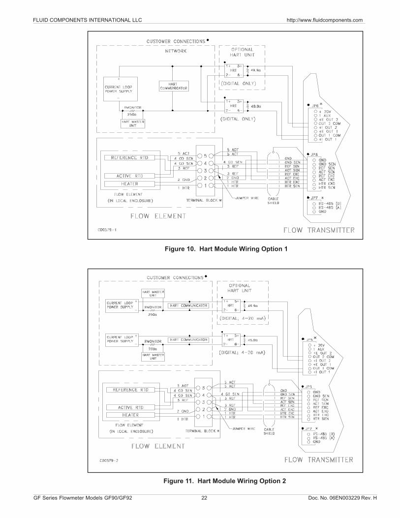
OUTPUT SIGNAL - The GF90/GF92 analog outputs are factory connected to the hart modules. The twodiagrams below shows recommended methods of connecting the HART modules to the customer’s system.
FCI recommends using the PC Interface Kit P/N: 014108-02 to connect the flow transmitter to a personalcomputer. The kit includes operation instructions and an adaptor for the RJ-12 to serial connection. Connectone end of the interface kit to the RJ-12 port and the other end to a DB pin connector. Plug the connectorinto the COM1 or COM2 port in the back of the computer terminal.
See instructions on how to use the serial communications in the next chapter.
HARTOptionInstallation
Figure 56. Wiring of DB-9 Connector
FLUID COMPONENTS INTERNATIONAL LLC http://www.fluidcomponents.com
GF Series Flowmeter Models GF90/GF92 22 Doc. No. 06EN003229 Rev. H
Figure 10. Hart Module Wiring Option 1
Figure 11. Hart Module Wiring Option 2
Ω
Ω
Ω
Ω
Ω
Ω
Ω
Doc. No. 06EN003229 Rev. H 23 GF Series Flowmeter Models GF90/GF92
FLUID COMPONENTS INTERNATIONAL LLC http://www.fluidcomponents.com
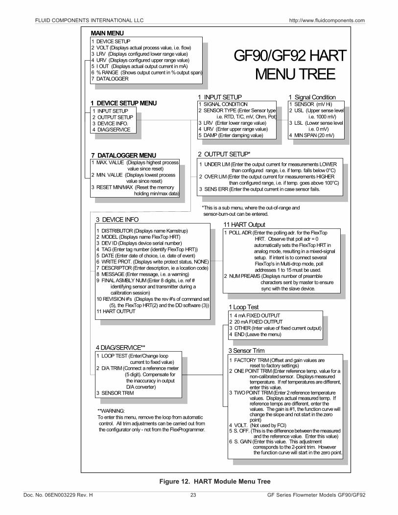
1 DEVICE SETUP2 VOLT (Displays actual process value, i.e. flow)3 LRV (Displays configured lower range value)4 URV (Displays configured upper range value)5 I OUT (Displays actual output current in mA)6 % RANGE (Shows output current in % output span)7 DATALOGGER
1 MAX. VALUE (Displays highest process value since reset)2 MIN. VALUE (Displays lowest process value since reset)3 RESET MIN/MAX (Reset the memory holding min/max data)
1 LOOP TEST (Enter/Change loop current to fixed value)2 D/A TRIM (Connect a reference meter (5 digit). Compensate for the inaccuracy in output D/A converter)3 SENSOR TRIM
1 SIGNAL CONDITION2 SENSOR TYPE (Enter Sensor type i.e. RTD, T/C, mV, Ohm, Pot)3 LRV (Enter lower range value)4 URV (Enter upper range value)5 DAMP (Enter damping value)
1 4 mA FIXED OUTPUT2 20 mA FIXED OUTPUT3 OTHER (Inter value of fixed current output)4 END (Leave the menu)
1 SENSOR (mV Hi)2 USL (Upper sense level i.e. 1000 mV)3 LSL (Lower sense level i.e. 0 mV)4 MIN SPAN (20 mV)
1 FACTORY TRIM (Offset and gain values are reset to factory settings)2 ONE POINT TRIM (Enter reference temp. value for a
non-calibrated sensor. Displays measured temperature. If ref temperatures are different, enter this value.
3 TWO POINT TRIM (Enter 2 reference temperature values. Displays actual measured temp. If reference temps are different, enter thevalues. The gain is #1, the function curve will change the slope and not start in the zero point)
4 VOLT. (Not used by FCI)5 S. OFF. (This is the difference between the measured
and the reference value. Enter this value)6 S. GAIN (Enter this value. This adjustment
corresponds to the 2-point trim. However the function curve will start in the zero point.
MAIN MENU
1 DEVICE SETUP MENU
7 DATALOGGER MENU
3 DEVICE INFO
2.1
4.1
1 DISTRIBUTOR (Displays name Kamstrup)2 MODEL (Displays name FlexTop HRT)3 DEV ID (Displays device serial number)4 TAG (Enter tag number (identify FlexTop HRT))5 DATE (Enter date of choice, i.e. date of event)6 WRITE PROT. (Displays write protect status, NONE)7 DESCRIPTOR (Enter description, ie a location code)8 MESSAGE (Enter message, i.e. a warning)9 FINAL ASMBLY NUM (Enter 8 digits, i.e. ref # identifying sensor and transmitter during a calibration session)10 REVISION #'s (Displays the rev #'s of command set (5), the FlexTop HRT(2) and the DD software (3))11 HART OUTPUT
1 POLL ADR (Enter the polling adr. for the FlexTop HRT. Observe that poll adr = 0 automatically sets the FlexTop HRT in analog mode, resulting in a mixed-signal setup. If intent is to connect several FlexTop's in Multi-drop mode, poll addresses 1 to 15 must be used.
2 NUM PREAMS (Displays number of preamble characters sent by master to ensure
sync with the slave device.
GF90/GF92 HART MENU TREE
1 INPUT SETUP2 OUTPUT SETUP3 DEVICE INFO.4 DIAG/SERVICE
1 INPUT SETUP 1 Signal Condition
1 UNDER LIM (Enter the output current for measurements LOWER than configured range, i.e. if temp. falls below 0°C)2 OVER LIM (Enter the output current for measurements HIGHER than configured range, i.e. if temp. goes above 100°C)3 SENS ERR (Enter the output current in case sensor fails.
2 OUTPUT SETUP*
11 HART Output
*This is a sub menu, where the out-of-range andsensor-burn-out can be entered.
4 DIAG/SERVICE**
1 Loop Test
3 Sensor Trim
**WARNING:To enter this menu, remove the loop from automatic control. All trim adjustments can be carried out from the configurator only - not from the FlexProgrammer.
Figure 12. HART Module Menu Tree
FLUID COMPONENTS INTERNATIONAL LLC http://www.fluidcomponents.com
GF Series Flowmeter Models GF90/GF92 24 Doc. No. 06EN003229 Rev. H
FoundationField Bus
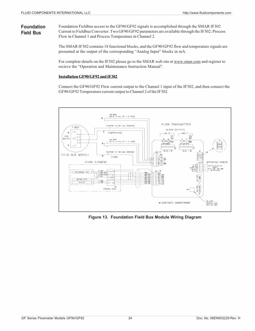
Figure 13. Foundation Field Bus Module Wiring Diagram
Foundation Fieldbus access to the GF90/GF92 signals is accomplished through the SMAR IF302Current to Fieldbus Converter. Two GF90/GF92 parameters are available through the IF302; ProcessFlow in Channel 1 and Process Temperature in Channel 2.
The SMAR IF302 contains 18 functional blocks, and the GF90/GF92 flow and temperature signals arepresented at the output of the corresponding “Analog Input” blocks in mA.
For complete details on the IF302 please go to the SMAR web site at www.smar.com and register torecieve the “Operation and Maintenance Instruction Manual”.
Installation GF90/GF92 and IF302
Connect the GF90/GF92 Flow current output to the Channel 1 input of the IF302, and then connect theGF90/GF92 Temperature current output to Channel 2 of the IF302.
Doc. No. 06EN003229 Rev. H 25 GF Series Flowmeter Models GF90/GF92
FLUID COMPONENTS INTERNATIONAL LLC http://www.fluidcomponents.com
IsolatedOutputOptionand 4-20 mAAdjustment
An isolated 4 to 20 milliampere (mA) output is an available option. The isolated output is available byconnecting a loop powered isolator module to the transmitter output. The modules have their own set ofoutput terminals which provide an isolated 4 to 20 mA output equal to the non-isolated instrument output.This one-to-one current isolation is used to prevent instrumentation ground loops. SeeFigure 14 for the wiring diagram to install the isolated output module.
Use of the isolator module will add a small signal conversion error to the instrument output and limit theoutput load to 350 ohms.
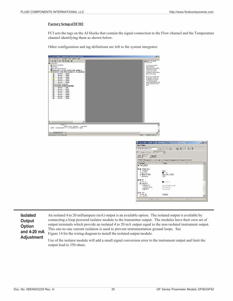
Factory Setup of IF302
FCI sets the tags on the AI blocks that contain the signal connection to the Flow channel and the Temperaturechannel identifying them as shown below.
Other configuration and tag definitions are left to the system integrator.
FLUID COMPONENTS INTERNATIONAL LLC http://www.fluidcomponents.com
GF Series Flowmeter Models GF90/GF92 26 Doc. No. 06EN003229 Rev. H
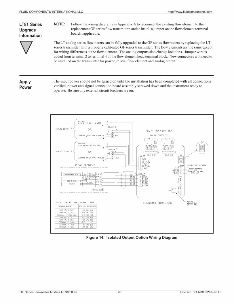
Figure 14. Isolated Output Option Wiring Diagram
NOTE: Follow the wiring diagrams in Appendix A to reconnect the existing flow element to thereplacement GF series flow transmitter, and to install a jumper on the flow element terminalboard if applicable.
The LT analog series flowmeters can be fully upgraded to the GF series flowmeters by replacing the LTseries transmitter with a properly calibrated GF series transmitter. The flow elements are the same exceptfor wiring differences at the flow element. The analog outputs also change locations. Jumper wire isadded from terminal 2 to terminal 4 of the flow element head terminal block. New connectors will need tobe installed on the transmitter for power, relays, flow element and analog output.
LT81 SeriesUpgradeInformation
The input power should not be turned on until the installation has been completed with all connectionsverified, power and signal connection board assembly screwed down and the instrument ready tooperate. Be sure any external circuit breakers are on.
ApplyPower
Doc. No. 06EN003229 Rev. H 27 GF Series Flow Meter Models GF90/GF92
FLUID COMPONENTS INTERNATIONAL LLC http://www.fluidcomponents.com
The instrument has been configured and calibrated to customer specifications. Each instrumentcontains distinct operating limits and units of measurement. This chapter will show how to determineand manipulate the configuration of the instrument.
ALERT: The flow transmitter contains electrostatic discharge (ESD) sensitive devices. Usestandard ESD precautions when handling the flow transmitter. See Chapter 3, Installationfor ESD details.
4. OperationIntroduction
Start UpProcedure
Operation
1. After the wiring has been verified, apply power to the flowmeter. (No special instructions forinstrument shutdown; turn operating power off.)
2. Then wait 10 minutes for warm-up. During this period the flowmeter may indicate high flow.3. After power up the instrument automatically enters the flow metering mode and the display sets to
normal operation.
DisplayThe flowmeter contains a 4 x 20 character LCD display. Flow rate, temperature, and system status areall accessible through the display.Initialization WindowWhen power is applied to the flowmeter the display will briefly show the initialization window. SeeFigure 15.
Figure 15. Initialization Window
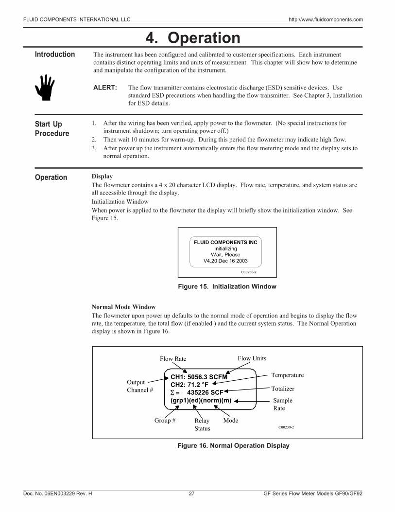
Normal Mode WindowThe flowmeter upon power up defaults to the normal mode of operation and begins to display the flowrate, the temperature, the total flow (if enabled ) and the current system status. The Normal Operationdisplay is shown in Figure 16.
CH1: 5056.3 SCFMCH2: 71.2 °F
435226 SCF(grp1)(ed)(norm)(m)
OutputChannel #
Flow Rate
Temperature
SampleRate
Σ =
ModeRelayStatus
Group #
Totalizer
C00239-2
Flow Units
Figure 16. Normal Operation Display
FLUID COMPONENTS INCInitializing
Wait, PleaseV4.20 Dec 16 2003
C00238-2
FLUID COMPONENTS INTERNATIONAL LLC http://www.fluidcomponents.com
GF Series Flow Meter Models GF90/GF92 28 Doc. No. 06EN003229 Rev. H
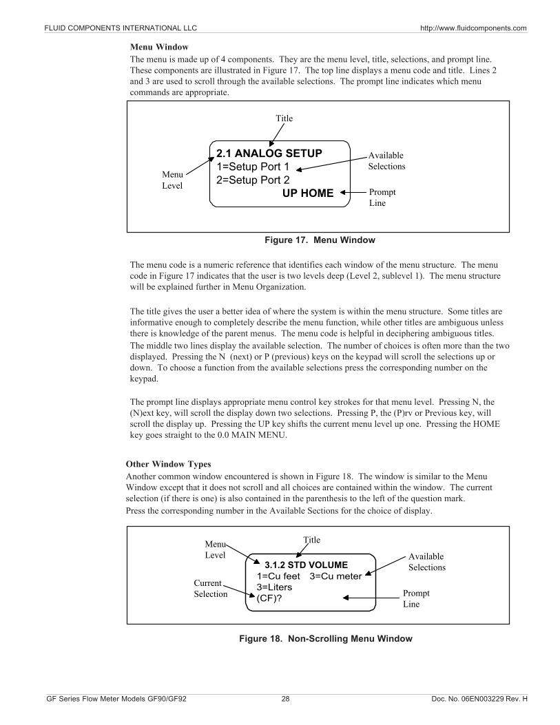
Menu WindowThe menu is made up of 4 components. They are the menu level, title, selections, and prompt line.These components are illustrated in Figure 17. The top line displays a menu code and title. Lines 2and 3 are used to scroll through the available selections. The prompt line indicates which menucommands are appropriate.
Figure 17. Menu Window
The menu code is a numeric reference that identifies each window of the menu structure. The menucode in Figure 17 indicates that the user is two levels deep (Level 2, sublevel 1). The menu structurewill be explained further in Menu Organization.
The title gives the user a better idea of where the system is within the menu structure. Some titles areinformative enough to completely describe the menu function, while other titles are ambiguous unlessthere is knowledge of the parent menus. The menu code is helpful in deciphering ambiguous titles.The middle two lines display the available selection. The number of choices is often more than the twodisplayed. Pressing the N (next) or P (previous) keys on the keypad will scroll the selections up ordown. To choose a function from the available selections press the corresponding number on thekeypad.
The prompt line displays appropriate menu control key strokes for that menu level. Pressing N, the(N)ext key, will scroll the display down two selections. Pressing P, the (P)rv or Previous key, willscroll the display up. Pressing the UP key shifts the current menu level up one. Pressing the HOMEkey goes straight to the 0.0 MAIN MENU.
2.1 ANALOG SETUP1=Setup Port 12=Setup Port 2
UP HOME
MenuLevel
Title
AvailableSelections
PromptLine
Other Window TypesAnother common window encountered is shown in Figure 18. The window is similar to the MenuWindow except that it does not scroll and all choices are contained within the window. The currentselection (if there is one) is also contained in the parenthesis to the left of the question mark.Press the corresponding number in the Available Sections for the choice of display.
3.1.2 STD VOLUME1=Cu feet3=Liters(CF)?
MenuLevel
Title
AvailableSelections
PromptLine
3=Cu meterCurrentSelection
Figure 18. Non-Scrolling Menu Window
Doc. No. 06EN003229 Rev. H 29 GF Series Flow Meter Models GF90/GF92
FLUID COMPONENTS INTERNATIONAL LLC http://www.fluidcomponents.com
1 2 3 Y N
4 5 6 _ .
7 8 9 P
ENTR 0 # HOME UP
•←←←←←
Table 4. Key Assignments for the Key Pad
See Table 4 for key pad assignments. At any time, the HOME key can be pressed and the main menuwill display. HOME can be used to escape from most routines, restart a progression into the menustructure, or quickly change from one area of the menu to another.
When (N)ext is displayed on the prompt line, more than two menu selections are available. Press N toscroll through all the selections.
The UP key, will back-out of a menu level. The menu moves back one level each time the UP key ispressed. The UP key only functions when UP is displayed on the prompt line.
To make a selection, press the numeric key associated with the desired menu selection. The selectiondoes not have to be displayed, but it must be one of the available selections.
Figure 19. Key Pad
Menu ControlThe prompt line displays appropriate key strokes for that menu level. If a key is pressed that is notvalid for that menu, Invalid Response will flash briefly across the prompt line. The key pad layout isshown in Figure 19.
KEY KEY NAME ACTION
0-9 NumericSelects options and enters numbers
Y Yes Enter a yes response
N No or (N)extEnter a no response or scrolls to the next screen
- Minus Enter a minus signDecimal Point Enter a decimal pointBack Space Moves cursor back one space
P (P)rv or Previous Scrolls to the previous screen
ENTR EnterEnters a numeric value or response
HOME HomeReturns to the Main Menu or escapes from routines
UP UpMove current menu up one level
Every path through the menu will eventually cause control to pass from the menu structure to a routinethat performs a task such as change a parameter value, initiate a test, or calibrate the system hardware.When the system is operating outside the menu structure, there are subtle differences in the userinterface. For example, the UP key may have no affect or the prompt line won't appear.
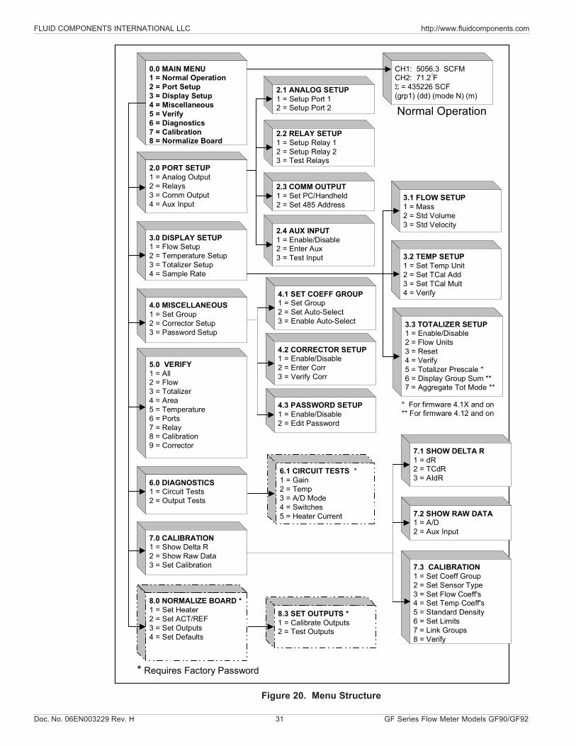
Menu OrganizationThe menu structure is divided into 8 major groups. The first menu option places the flow transmitter'sdisplay into the Normal Display mode. When the system is in this mode, flow and temperaturemeasurements are displayed. While in the Normal Display mode, pressing any key will cause the mainmenu to display. Figure 20 shows the entire menu structure.
Menu selections two through eight allow the configuration of the flowmeter to be checked andmanipulated. Table 5 summarizes the functions contained in each menu group.
FLUID COMPONENTS INTERNATIONAL LLC http://www.fluidcomponents.com
GF Series Flow Meter Models GF90/GF92 30 Doc. No. 06EN003229 Rev. H
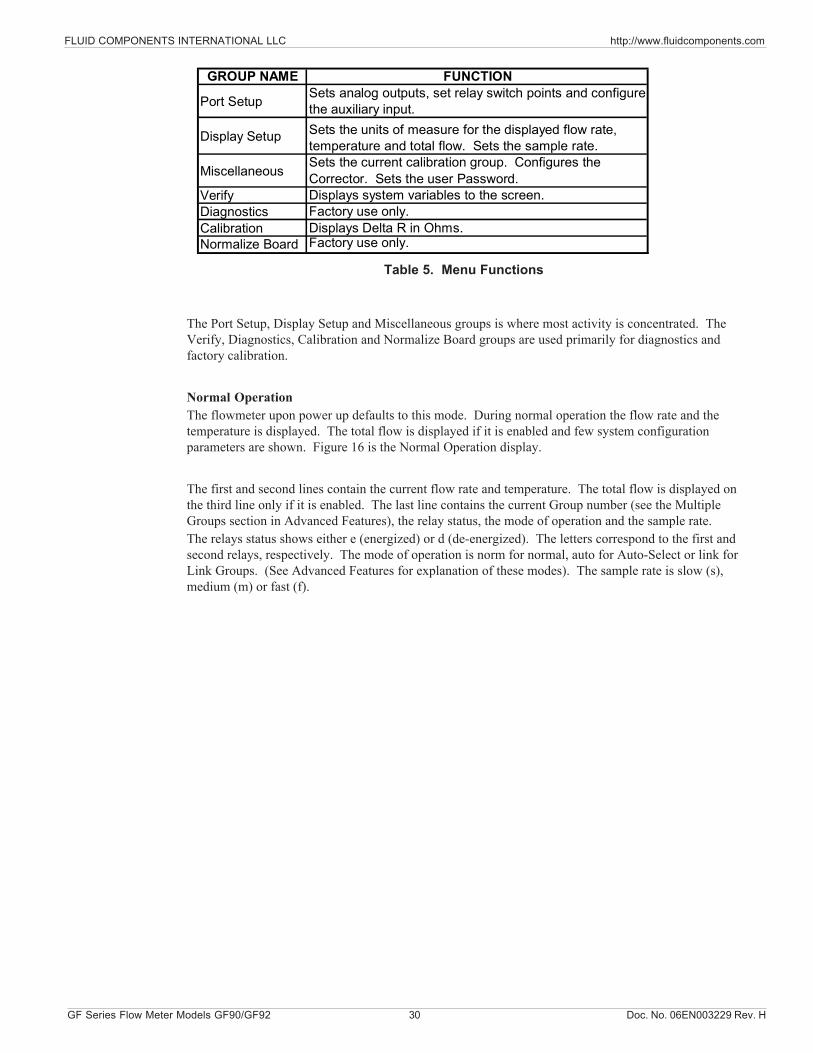
Table 5. Menu Functions
The Port Setup, Display Setup and Miscellaneous groups is where most activity is concentrated. TheVerify, Diagnostics, Calibration and Normalize Board groups are used primarily for diagnostics andfactory calibration.
Normal OperationThe flowmeter upon power up defaults to this mode. During normal operation the flow rate and thetemperature is displayed. The total flow is displayed if it is enabled and few system configurationparameters are shown. Figure 16 is the Normal Operation display.
The first and second lines contain the current flow rate and temperature. The total flow is displayed onthe third line only if it is enabled. The last line contains the current Group number (see the MultipleGroups section in Advanced Features), the relay status, the mode of operation and the sample rate.The relays status shows either e (energized) or d (de-energized). The letters correspond to the first andsecond relays, respectively. The mode of operation is norm for normal, auto for Auto-Select or link forLink Groups. (See Advanced Features for explanation of these modes). The sample rate is slow (s),medium (m) or fast (f).
GROUP NAME FUNCTION
Port Setup Sets analog outputs, set relay switch points and configure the auxiliary input.
Display Setup Sets the units of measure for the displayed flow rate, temperature and total flow. Sets the sample rate.
Miscellaneous Sets the current calibration group. Configures the Corrector. Sets the user Password.
Verify Displays system variables to the screen.Diagnostics Factory use only.Calibration Displays Delta R in Ohms.Normalize Board Factory use only.
Doc. No. 06EN003229 Rev. H 31 GF Series Flow Meter Models GF90/GF92
FLUID COMPONENTS INTERNATIONAL LLC http://www.fluidcomponents.com
Figure 20. Menu Structure
0.0 MAIN MENU1 = Normal Operation2 = Port Setup3 = Display Setup4 = Miscellaneous5 = Verify6 = Diagnostics7 = Calibration8 = Normalize Board
2.0 PORT SETUP1 = Analog Output2 = Relays3 = Comm Output4 = Aux Input
3.0 DISPLAY SETUP1 = Flow Setup2 = Temperature Setup3 = Totalizer Setup4 = Sample Rate
4.0 MISCELLANEOUS1 = Set Group2 = Corrector Setup3 = Password Setup
5.0 VERIFY1 = All2 = Flow3 = Totalizer4 = Area5 = Temperature6 = Ports7 = Relay8 = Calibration9 = Corrector
6.0 DIAGNOSTICS1 = Circuit Tests2 = Output Tests
7.0 CALIBRATION1 = Show Delta R2 = Show Raw Data3 = Set Calibration
8.0 NORMALIZE BOARD *1 = Set Heater2 = Set ACT/REF3 = Set Outputs4 = Set Defaults
2.1 ANALOG SETUP1 = Setup Port 12 = Setup Port 2
2.2 RELAY SETUP1 = Setup Relay 12 = Setup Relay 23 = Test Relays
2.3 COMM OUTPUT1 = Set PC/Handheld2 = Set 485 Address
2.4 AUX INPUT1 = Enable/Disable2 = Enter Aux3 = Test Input
4.1 SET COEFF GROUP1 = Set Group2 = Set Auto-Select3 = Enable Auto-Select
4.2 CORRECTOR SETUP1 = Enable/Disable2 = Enter Corr3 = Verify Corr
4.3 PASSWORD SETUP1 = Enable/Disable2 = Edit Password
7.3 CALIBRATION1 = Set Coeff Group2 = Set Sensor Type3 = Set Flow Coeff's4 = Set Temp Coeff's5 = Standard Density6 = Set Limits7 = Link Groups8 = Verify
CH1: 5056.3 SCFMCH2: 71.2 FΣ = 435226 SCF(grp1) (dd) (mode N) (m)
Normal Operation
3.1 FLOW SETUP1 = Mass2 = Std Volume3 = Std Velocity
3.2 TEMP SETUP1 = Set Temp Unit2 = Set TCal Add3 = Set TCal Mult4 = Verify
3.3 TOTALIZER SETUP1 = Enable/Disable2 = Flow Units3 = Reset4 = Verify5 = Totalizer Prescale *6 = Display Group Sum **7 = Aggregate Tot Mode **
8.3 SET OUTPUTS *1 = Calibrate Outputs2 = Test Outputs
6.1 CIRCUIT TESTS *1 = Gain2 = Temp3 = A/D Mode4 = Switches5 = Heater Current
* Requires Factory Password
* For firmware 4.1X and on** For firmware 4.12 and on
7.1 SHOW DELTA R1 = dR2 = TCdR3 = AIdR
7.2 SHOW RAW DATA1 = A/D2 = Aux Input
FLUID COMPONENTS INTERNATIONAL LLC http://www.fluidcomponents.com
GF Series Flow Meter Models GF90/GF92 32 Doc. No. 06EN003229 Rev. H
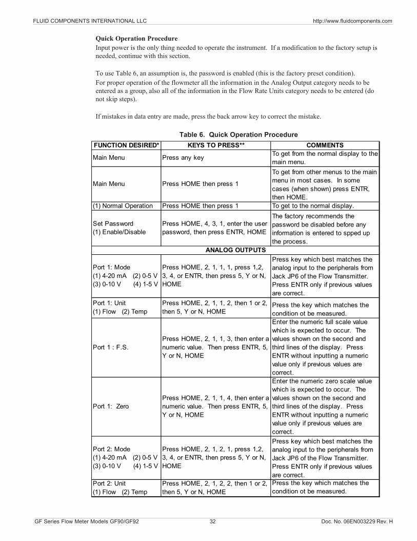
Quick Operation ProcedureInput power is the only thing needed to operate the instrument. If a modification to the factory setup isneeded, continue with this section.
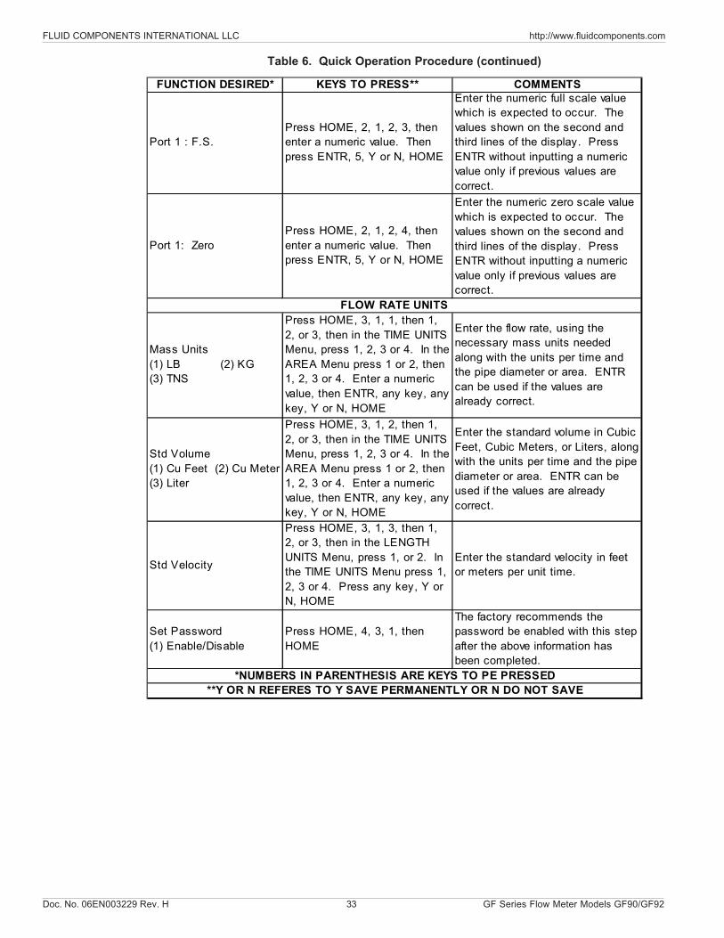
To use Table 6, an assumption is, the password is enabled (this is the factory preset condition).For proper operation of the flowmeter all the information in the Analog Output category needs to beentered as a group, also all of the information in the Flow Rate Units category needs to be entered (donot skip steps).
If mistakes in data entry are made, press the back arrow key to correct the mistake.
Table 6. Quick Operation ProcedureFUNCTION DESIRED* KEYS TO PRESS** COMMENTS
Main Menu Press any key To get from the normal display to the main menu.
Main Menu Press HOME then press 1
To get from other menus to the main menu in most cases. In some cases (when shown) press ENTR, then HOME.
(1) Normal Operation Press HOME then press 1 To get to the normal display.
Set Password (1) Enable/Disable
Press HOME, 4, 3, 1, enter the user password, then press ENTR, HOME
The factory recommends the password be disabled before any information is entered to spped up the process.
Port 1: Mode (1) 4-20 mA (2) 0-5 V (3) 0-10 V (4) 1-5 V
Press HOME, 2, 1, 1, 1, press 1,2, 3, 4, or ENTR, then press 5, Y or N, HOME
Press key which best matches the analog input to the peripherals from Jack JP6 of the Flow Transmitter. Press ENTR only if previous values are correct.
Port 1: Unit (1) Flow (2) Temp
Press HOME, 2, 1, 1, 2, then 1 or 2, then 5, Y or N, HOME
Press the key which matches the condition ot be measured.
Port 1 : F.S.Press HOME, 2, 1, 1, 3, then enter a numeric value. Then press ENTR, 5, Y or N, HOME
Enter the numeric full scale value which is expected to occur. The values shown on the second and third lines of the display. Press ENTR without inputting a numeric value only if previous values are correct.
Port 1: ZeroPress HOME, 2, 1, 1, 4, then enter a numeric value. Then press ENTR, 5, Y or N, HOME
Enter the numeric zero scale value which is expected to occur. The values shown on the second and third lines of the display. Press ENTR without inputting a numeric value only if previous values are correct.
Port 2: Mode (1) 4-20 mA (2) 0-5 V (3) 0-10 V (4) 1-5 V
Press HOME, 2, 1, 2, 1, press 1,2, 3, 4, or ENTR, then press 5, Y or N, HOME
Press key which best matches the analog input to the peripherals from Jack JP6 of the Flow Transmitter. Press ENTR only if previous values are correct.
Port 2: Unit (1) Flow (2) Temp
Press HOME, 2, 1, 2, 2, then 1 or 2, then 5, Y or N, HOME
Press the key which matches the condition ot be measured.
ANALOG OUTPUTS
Doc. No. 06EN003229 Rev. H 33 GF Series Flow Meter Models GF90/GF92
FLUID COMPONENTS INTERNATIONAL LLC http://www.fluidcomponents.com
FUNCTION DESIRED* KEYS TO PRESS** COMMENTS
Port 1 : F.S.Press HOME, 2, 1, 2, 3, then enter a numeric value. Then press ENTR, 5, Y or N, HOME
Enter the numeric full scale value which is expected to occur. The values shown on the second and third lines of the display. Press ENTR without inputting a numeric value only if previous values are correct.
Port 1: ZeroPress HOME, 2, 1, 2, 4, then enter a numeric value. Then press ENTR, 5, Y or N, HOME
Enter the numeric zero scale value which is expected to occur. The values shown on the second and third lines of the display. Press ENTR without inputting a numeric value only if previous values are correct.
Mass Units (1) LB (2) KG (3) TNS
Press HOME, 3, 1, 1, then 1, 2, or 3, then in the TIME UNITS Menu, press 1, 2, 3 or 4. In the AREA Menu press 1 or 2, then 1, 2, 3 or 4. Enter a numeric value, then ENTR, any key, any key, Y or N, HOME
Enter the flow rate, using the necessary mass units needed along with the units per time and the pipe diameter or area. ENTR can be used if the values are already correct.
Std Volume (1) Cu Feet (2) Cu Meter (3) Liter
Press HOME, 3, 1, 2, then 1, 2, or 3, then in the TIME UNITS Menu, press 1, 2, 3 or 4. In the AREA Menu press 1 or 2, then 1, 2, 3 or 4. Enter a numeric value, then ENTR, any key, any key, Y or N, HOME
Enter the standard volume in Cubic Feet, Cubic Meters, or Liters, along with the units per time and the pipe diameter or area. ENTR can be used if the values are already correct.
Std Velocity
Press HOME, 3, 1, 3, then 1, 2, or 3, then in the LENGTH UNITS Menu, press 1, or 2. In the TIME UNITS Menu press 1, 2, 3 or 4. Press any key, Y or N, HOME
Enter the standard velocity in feet or meters per unit time.
Set Password (1) Enable/Disable
Press HOME, 4, 3, 1, then HOME
The factory recommends the password be enabled with this step after the above information has been completed.
FLOW RATE UNITS
*NUMBERS IN PARENTHESIS ARE KEYS TO PE PRESSED**Y OR N REFERES TO Y SAVE PERMANENTLY OR N DO NOT SAVE
Table 6. Quick Operation Procedure (continued)
FLUID COMPONENTS INTERNATIONAL LLC http://www.fluidcomponents.com
GF Series Flow Meter Models GF90/GF92 34 Doc. No. 06EN003229 Rev. H
Configuring the FlowmeterThere are several parameters that can be modified to customize the system. This section describeshow the flowmeter can be customized to best fit requirements.
Password ProtectionBefore the flowmeter configuration is customized, access to the system parameters must be had.Two levels of password protection affect access to these parameters.
Factory LevelThe highest level of protection requires a system password for access. This password preventsthe user from inadvertently changing variables associated with the system calibration or otherparameters that require factory resources to properly set.
User LevelThe second level of protection requires a user password for access. This password provides theuser with the ability to limit access to parameters that affect the way the system operates. Thedefault user password is 123 and can be changed to any combination of up to 12 characters inlength.
Both levels of password protection can be enabled or disabled. When the system leaves thefactory, the factory level and user passwords are enabled. No password is required to enable alevel of protection, but the appropriate password is required to disable protection.
NOTE: The user password is set to 123 when the system is shipped.
To edit the user password:
1. From the Main Menu press 4. The 4.0 MISCELLANEOUS menu title will appear.2. Press 3, Password Setup.3. Press 2, Edit Password.4. If password protection is enabled enter the current password.5. Enter the new password of up to 12 characters.6. When prompted to Save Permanently enter Y for yes.
To enable and disable the password protection:
1. From the Main Menu press 4. The 4.0 MISCELLANEOUS menu title will appear.2. Press 3, Password Setup.3. Press 1, Enable/Disable Password.4. Enter the user password if prompted to do so.5. The password protection will be toggled on or off depending on its previous state.
Selecting Units of Measure
NOTE: By answering the prompt, Save permanently?, with a N or by pressing the HOME key, theflowmeter will revert to the previously saved units of measure when the power is cycled.
Doc. No. 06EN003229 Rev. H 35 GF Series Flow Meter Models GF90/GF92
FLUID COMPONENTS INTERNATIONAL LLC http://www.fluidcomponents.com
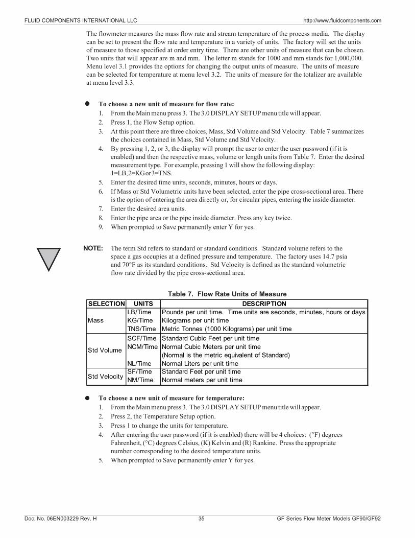
The flowmeter measures the mass flow rate and stream temperature of the process media. The displaycan be set to present the flow rate and temperature in a variety of units. The factory will set the unitsof measure to those specified at order entry time. There are other units of measure that can be chosen.Two units that will appear are m and mm. The letter m stands for 1000 and mm stands for 1,000,000.Menu level 3.1 provides the options for changing the output units of measure. The units of measurecan be selected for temperature at menu level 3.2. The units of measure for the totalizer are availableat menu level 3.3.
To choose a new unit of measure for flow rate:1. From the Main menu press 3. The 3.0 DISPLAY SETUP menu title will appear.2. Press 1, the Flow Setup option.3. At this point there are three choices, Mass, Std Volume and Std Velocity. Table 7 summarizes
the choices contained in Mass, Std Volume and Std Velocity.4. By pressing 1, 2, or 3, the display will prompt the user to enter the user password (if it is
enabled) and then the respective mass, volume or length units from Table 7. Enter the desiredmeasurement type. For example, pressing 1 will show the following display:1=LB, 2=KG or 3=TNS.
5. Enter the desired time units, seconds, minutes, hours or days.6. If Mass or Std Volumetric units have been selected, enter the pipe cross-sectional area. There
is the option of entering the area directly or, for circular pipes, entering the inside diameter.7. Enter the desired area units.8. Enter the pipe area or the pipe inside diameter. Press any key twice.9. When prompted to Save permanently enter Y for yes.
NOTE: The term Std refers to standard or standard conditions. Standard volume refers to thespace a gas occupies at a defined pressure and temperature. The factory uses 14.7 psiaand 70°F as its standard conditions. Std Velocity is defined as the standard volumetricflow rate divided by the pipe cross-sectional area.
Table 7. Flow Rate Units of Measure
To choose a new unit of measure for temperature:1. From the Main menu press 3. The 3.0 DISPLAY SETUP menu title will appear.2. Press 2, the Temperature Setup option.3. Press 1 to change the units for temperature.4. After entering the user password (if it is enabled) there will be 4 choices: (°F) degrees
Fahrenheit, (°C) degrees Celsius, (K) Kelvin and (R) Rankine. Press the appropriatenumber corresponding to the desired temperature units.
5. When prompted to Save permanently enter Y for yes.
SELECTION UNITS DESCRIPTION
MassLB/Time KG/Time TNS/Time
Pounds per unit time. Time units are seconds, minutes, hours or days Kilograms per unit time Metric Tonnes (1000 Kilograms) per unit time
Std Volume
SCF/Time NCM/Time . NL/Time
Standard Cubic Feet per unit time Normal Cubic Meters per unit time (Normal is the metric equivalent of Standard) Normal Liters per unit time
Std VelocitySF/Time NM/Time
Standard Feet per unit time Normal meters per unit time
FLUID COMPONENTS INTERNATIONAL LLC http://www.fluidcomponents.com
GF Series Flow Meter Models GF90/GF92 36 Doc. No. 06EN003229 Rev. H
To choose a new unit of measure for total flow:
1. From the Main menu press 3. The 3.0 DISPLAY SETUP menu title will appear.2. Press 3, the Totalizer Setup option.3. Press 2, Flow Units, to change the units for total flow.4. There is the option of standard volumetric units or mass units. See Table 3-4 for a
description of the available choices. Press 1 or 2.5. After entering the user password (if it is enabled) the user will be prompted with
standard volumetric or mass units. Enter the desired total flow units.6. The user will be prompted to enter the pipe cross-sectional area. The user has the
option of entering the area directly or, for circular pipes, entering the inside diameter.Enter the method desired.
7. Enter the desired area units.8. Enter the value of the pipe area or the pipe inside diameter. Press any key twice.9. When prompted to Save permanently enter Y for yes.
To choose Totalizer Prescaler for total flow (for 4.10 firmware and above):
1. From the Main menu press 3. The 3.0 DISPLAY SETUP menu title will appear.2. Press 3, the Totalizer Setup option.3. Press 5, Totalizer Prescaler, to change between prescale values of 0, .001 or 1000.4. Press 0 for no prescale, or press 1 for a prescale value of .001, or press 2 for a prescale
value of 1000.
To choose Display Group Sum for total flow (for 4.12 firmware and above):
1. From the Main menu press 3. The 3.0 DISPLAY SETUP menu title will appear.2. Press 3, the Totalizer Setup option.3. Press 6, the Display Group Sum.
The totalized flow for the first group will be displayed. Pressing any key will display the totalizedflow for the second group if the second group is enabled. Pressing any key will display thetotalized flow for the third group if the third group is enabled.
The group totals will be displayed regardless if they have been initialized. These values can bereset by switching to each group and individually resetting each one or doing a reset all from menu3.3.3.
To choose Aggregate Tot Mode for total flow (for 4.12 firmware and above):
1. From the Main menu press 3. The 3.0 DISPLAY SETUP menu title will appear.2. Press 3, the Totalizer Setup option.3. Press 7, Aggregate Tot Mode, to turn on or off the aggregate total mode.
This setting is saved in EEPROM and recalled when the system is reset. When the aggregate modeis enabled, the following parameters must be the same for all the groups that are linked; totalizerprescale, totalizer mode (fixed or float) and the totalizer units. If all the parameters do not match, thetotalizer display will show "AGGREGATE TOT ERROR".
Doc. No. 06EN003229 Rev. H 37 GF Series Flow Meter Models GF90/GF92
FLUID COMPONENTS INTERNATIONAL LLC http://www.fluidcomponents.com
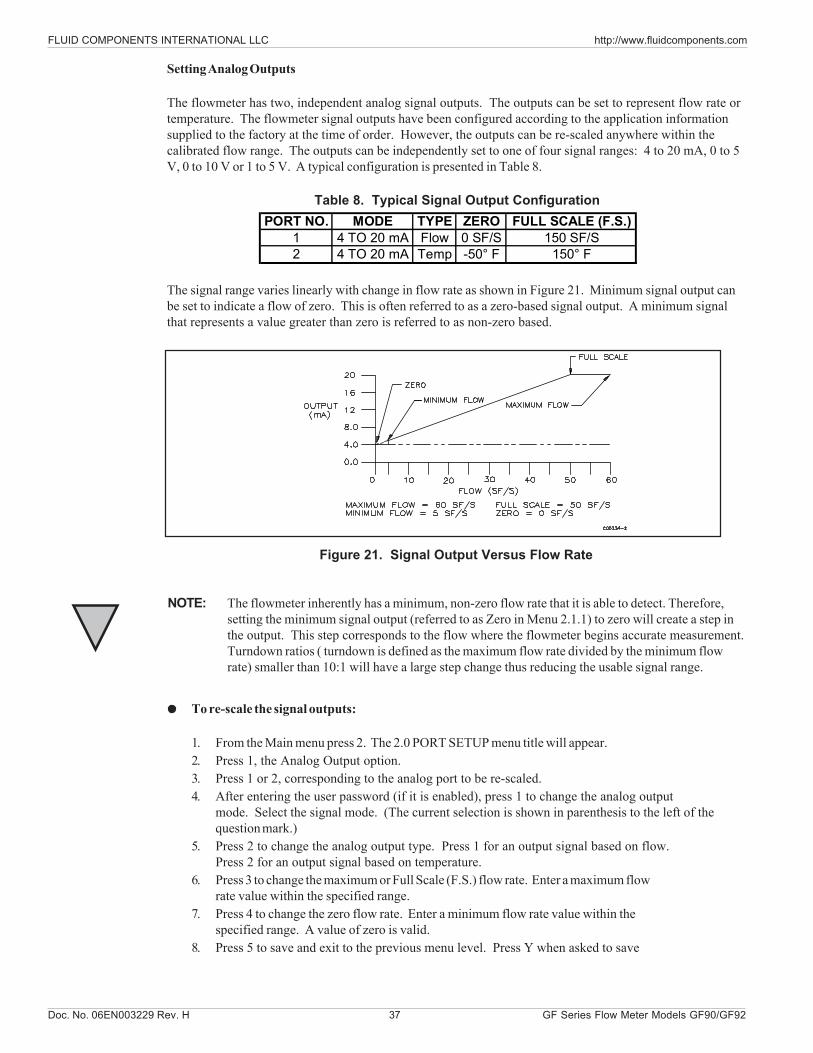
Setting Analog Outputs
The flowmeter has two, independent analog signal outputs. The outputs can be set to represent flow rate ortemperature. The flowmeter signal outputs have been configured according to the application informationsupplied to the factory at the time of order. However, the outputs can be re-scaled anywhere within thecalibrated flow range. The outputs can be independently set to one of four signal ranges: 4 to 20 mA, 0 to 5V, 0 to 10 V or 1 to 5 V. A typical configuration is presented in Table 8.
Table 8. Typical Signal Output Configuration
The signal range varies linearly with change in flow rate as shown in Figure 21. Minimum signal output canbe set to indicate a flow of zero. This is often referred to as a zero-based signal output. A minimum signalthat represents a value greater than zero is referred to as non-zero based.
PORT NO. MODE TYPE ZERO FULL SCALE (F.S.)1 4 TO 20 mA Flow 0 SF/S 150 SF/S2 4 TO 20 mA Temp -50° F 150° F
Figure 21. Signal Output Versus Flow Rate
NOTE: The flowmeter inherently has a minimum, non-zero flow rate that it is able to detect. Therefore,setting the minimum signal output (referred to as Zero in Menu 2.1.1) to zero will create a step inthe output. This step corresponds to the flow where the flowmeter begins accurate measurement.Turndown ratios ( turndown is defined as the maximum flow rate divided by the minimum flowrate) smaller than 10:1 will have a large step change thus reducing the usable signal range.
To re-scale the signal outputs:
1. From the Main menu press 2. The 2.0 PORT SETUP menu title will appear.2. Press 1, the Analog Output option.3. Press 1 or 2, corresponding to the analog port to be re-scaled.4. After entering the user password (if it is enabled), press 1 to change the analog output
mode. Select the signal mode. (The current selection is shown in parenthesis to the left of thequestion mark.)
5. Press 2 to change the analog output type. Press 1 for an output signal based on flow.Press 2 for an output signal based on temperature.
6. Press 3 to change the maximum or Full Scale (F.S.) flow rate. Enter a maximum flowrate value within the specified range.
7. Press 4 to change the zero flow rate. Enter a minimum flow rate value within thespecified range. A value of zero is valid.
8. Press 5 to save and exit to the previous menu level. Press Y when asked to save
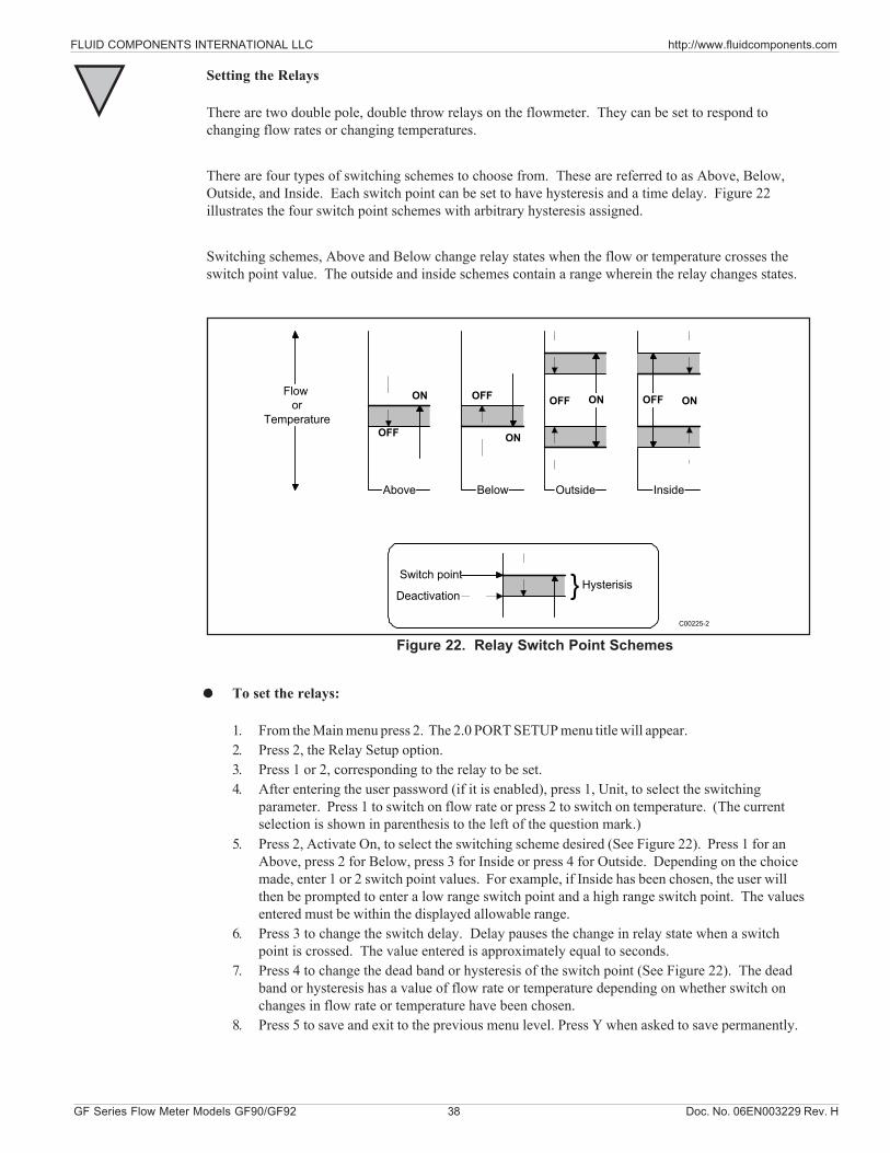
FLUID COMPONENTS INTERNATIONAL LLC http://www.fluidcomponents.com
GF Series Flow Meter Models GF90/GF92 38 Doc. No. 06EN003229 Rev. H
Setting the Relays
There are two double pole, double throw relays on the flowmeter. They can be set to respond tochanging flow rates or changing temperatures.
There are four types of switching schemes to choose from. These are referred to as Above, Below,Outside, and Inside. Each switch point can be set to have hysteresis and a time delay. Figure 22illustrates the four switch point schemes with arbitrary hysteresis assigned.
Switching schemes, Above and Below change relay states when the flow or temperature crosses theswitch point value. The outside and inside schemes contain a range wherein the relay changes states.
Above
OFF
ON
Below
OFF
ON
Outside
ONOFF
Inside
ONOFF
Switch point
Deactivation Hysterisis
C00225-2
Flow or
Temperature
Figure 22. Relay Switch Point Schemes
To set the relays:
1. From the Main menu press 2. The 2.0 PORT SETUP menu title will appear.2. Press 2, the Relay Setup option.3. Press 1 or 2, corresponding to the relay to be set.4. After entering the user password (if it is enabled), press 1, Unit, to select the switching
parameter. Press 1 to switch on flow rate or press 2 to switch on temperature. (The currentselection is shown in parenthesis to the left of the question mark.)
5. Press 2, Activate On, to select the switching scheme desired (See Figure 22). Press 1 for anAbove, press 2 for Below, press 3 for Inside or press 4 for Outside. Depending on the choicemade, enter 1 or 2 switch point values. For example, if Inside has been chosen, the user willthen be prompted to enter a low range switch point and a high range switch point. The valuesentered must be within the displayed allowable range.
6. Press 3 to change the switch delay. Delay pauses the change in relay state when a switchpoint is crossed. The value entered is approximately equal to seconds.
7. Press 4 to change the dead band or hysteresis of the switch point (See Figure 22). The deadband or hysteresis has a value of flow rate or temperature depending on whether switch onchanges in flow rate or temperature have been chosen.
8. Press 5 to save and exit to the previous menu level. Press Y when asked to save permanently.
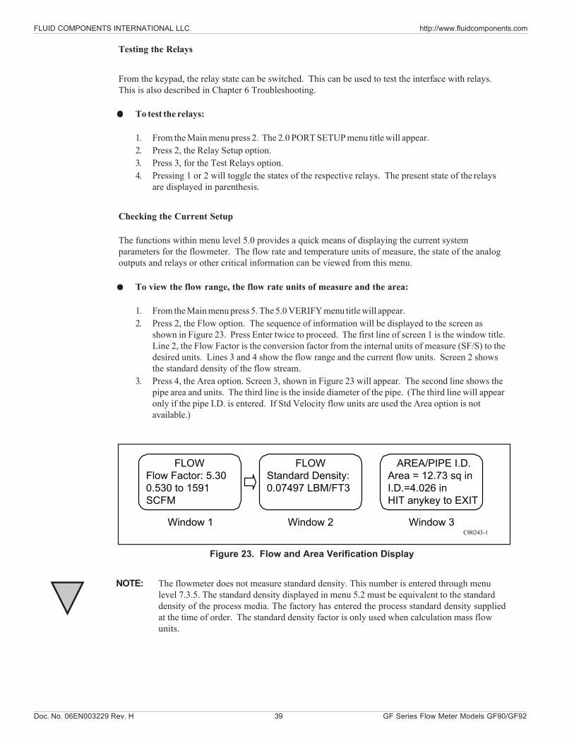
Doc. No. 06EN003229 Rev. H 39 GF Series Flow Meter Models GF90/GF92
FLUID COMPONENTS INTERNATIONAL LLC http://www.fluidcomponents.com
Testing the Relays
From the keypad, the relay state can be switched. This can be used to test the interface with relays.This is also described in Chapter 6 Troubleshooting.
To test the relays:
1. From the Main menu press 2. The 2.0 PORT SETUP menu title will appear.2. Press 2, the Relay Setup option.3. Press 3, for the Test Relays option.4. Pressing 1 or 2 will toggle the states of the respective relays. The present state of the relays
are displayed in parenthesis.
Checking the Current Setup
The functions within menu level 5.0 provides a quick means of displaying the current systemparameters for the flowmeter. The flow rate and temperature units of measure, the state of the analogoutputs and relays or other critical information can be viewed from this menu.
To view the flow range, the flow rate units of measure and the area:
1. From the Main menu press 5. The 5.0 VERIFY menu title will appear.2. Press 2, the Flow option. The sequence of information will be displayed to the screen as
shown in Figure 23. Press Enter twice to proceed. The first line of screen 1 is the window title.Line 2, the Flow Factor is the conversion factor from the internal units of measure (SF/S) to thedesired units. Lines 3 and 4 show the flow range and the current flow units. Screen 2 showsthe standard density of the flow stream.
3. Press 4, the Area option. Screen 3, shown in Figure 23 will appear. The second line shows thepipe area and units. The third line is the inside diameter of the pipe. (The third line will appearonly if the pipe I.D. is entered. If Std Velocity flow units are used the Area option is notavailable.)
FLOWFlow Factor: 5.300.530 to 1591SCFM
FLOWStandard Density:0.07497 LBM/FT3
Window 1 Window 2
AREA/PIPE I.D.Area = 12.73 sq inI.D.=4.026 inHIT anykey to EXIT
Window 3C00243-1
Figure 23. Flow and Area Verification Display
NOTE: The flowmeter does not measure standard density. This number is entered through menulevel 7.3.5. The standard density displayed in menu 5.2 must be equivalent to the standarddensity of the process media. The factory has entered the process standard density suppliedat the time of order. The standard density factor is only used when calculation mass flowunits.
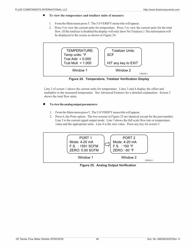
FLUID COMPONENTS INTERNATIONAL LLC http://www.fluidcomponents.com
GF Series Flow Meter Models GF90/GF92 40 Doc. No. 06EN003229 Rev. H
To view the temperature and totalizer units of measure:
1. From the Main menu press 5. The 5.0 VERIFY menu title will appear.2. Press 5 to view the current units for temperature. Press 3 to view the current units for the total
flow. (If the totalizer is disabled the display will only show No Totalizer.) The information willbe displayed to the screen as shown in Figure 24.
TEMPERATURE:Temp units: °FTcal Add = 0.000Tcal Mult = 1.000
Totalizer Units:SCF
HIT any key to EXIT
Window 1 Window 2C00244-1
Figure 24. Temperature, Totalizer Verification Display
Line 2 of screen 1 shows the current units for temperature. Lines 3 and 4 display the offset andmultiplier to the measured temperature. See Advanced Features for a detailed explanation. Screen 2shows the total flow units.
To view the analog output parameters:
1. From the Main menu press 5. The 5.0 VERIFY menu title will appear.2. Press 6, the Ports option. The two screens in Figure 25 are identical except for the port number.
Line 2 is the current signal output mode. Line 3 shows the full scale flow rate or temperaturevalue and the appropriate units. Line 4 is the zero value. Press any key for screen 2.
Figure 25. Analog Output Verification
PORT 1Mode: 4-20 mAF.S. : 1591 SCFMZERO: 0.00 SCFM
PORT 2Mode: 4-20 mAF.S. : 150 °FZERO: -50 °F
Window 1 Window 2C00245-1
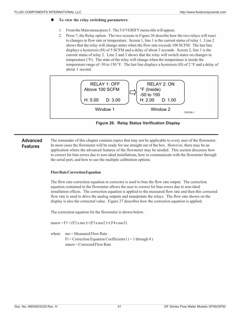
Doc. No. 06EN003229 Rev. H 41 GF Series Flow Meter Models GF90/GF92
FLUID COMPONENTS INTERNATIONAL LLC http://www.fluidcomponents.com
To view the relay switching parameters:
1. From the Main menu press 5. The 5.0 VERIFY menu title will appear.2. Press 7, the Relay option. The two screens in Figure 26 describe how the two relays will react
to changes in flow rate or temperature. Screen 1, line 1 is the current status of relay 1. Line 2shows that the relay will change states when the flow rate exceeds 100 SCFM. The last linedisplays a hysteresis (H) of 5 SCFM and a delay of about 3 seconds. Screen 2, line 1 is thecurrent status of relay 2. Line 2 and 3 shows that the relay will switch states on changes intemperature (°F). The state of the relay will change when the temperature is inside thetemperature range of -50 to 150 °F. The last line displays a hysteresis (H) of 2 °F and a delay ofabout 1 second.
RELAY 1: OFFAbove 100 SCFM
H: 5.00 D: 3.00
RELAY 2: ON°F (Inside)-50 to 150H: 2.00 D: 1.00
Window 1 Window 2C00246-1
Figure 26. Relay Status Verification Display
The remainder of this chapter contains topics that may not be applicable to every user of the flowmeter.In most cases the flowmeter will be ready for use straight out of the box. However, there may be anapplication where the advanced features of the flowmeter may be needed. This section discusses howto correct for bias errors due to non-ideal installations, how to communicate with the flowmeter throughthe serial port, and how to use the multiple calibration options.
Flow Rate Correction Equation
The flow rate correction equation or corrector is used to bias the flow rate output. The correctionequation contained in the flowmeter allows the user to correct for bias errors due to non-idealinstallation effects. The correction equation is applied to the measured flow rate and then this correctedflow rate is used to drive the analog outputs and manipulate the relays. The flow rate shown on thedisplay is also the corrected value. Figure 27 describes how the correction equation is applied.
The correction equation for the flowmeter is shown below.
mnew = F1 + (F2 x mo )+ (F3 x mo2 )+( F4 x mo3)
where mo = Measured Flow RateFi = Correction Equation Coefficients ( i = 1 through 4 )mnew = Corrected Flow Rate
AdvancedFeatures
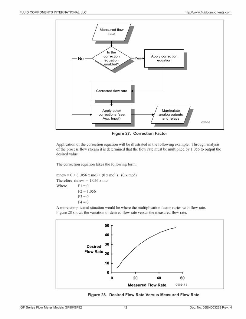
FLUID COMPONENTS INTERNATIONAL LLC http://www.fluidcomponents.com
GF Series Flow Meter Models GF90/GF92 42 Doc. No. 06EN003229 Rev. H
Figure 27. Correction Factor
Application of the correction equation will be illustrated in the following example. Through analysisof the process flow stream it is determined that the flow rate must be multiplied by 1.056 to output thedesired value.
The correction equation takes the following form:
mnew = 0 + (1.056 x mo) + (0 x mo2 )+ (0 x mo3 )Therefore mnew = 1.056 x moWhere F1 = 0
F2 = 1.056F3 = 0F4 = 0
A more complicated situation would be where the multiplication factor varies with flow rate.Figure 28 shows the variation of desired flow rate versus the measured flow rate.
Is thecorrectionequationenabled?
Apply correctionequation
Corrected flow rate
Apply othercorrections (see
Aux. Input)
Yes
C00247-2
Manipulateanalog outputs
and relays
Measured flowrate
No
Measured Flow Rate
DesiredFlow Rate
0
10
20
30
40
50
0 20 40 60C00248-1
Figure 28. Desired Flow Rate Versus Measured Flow Rate
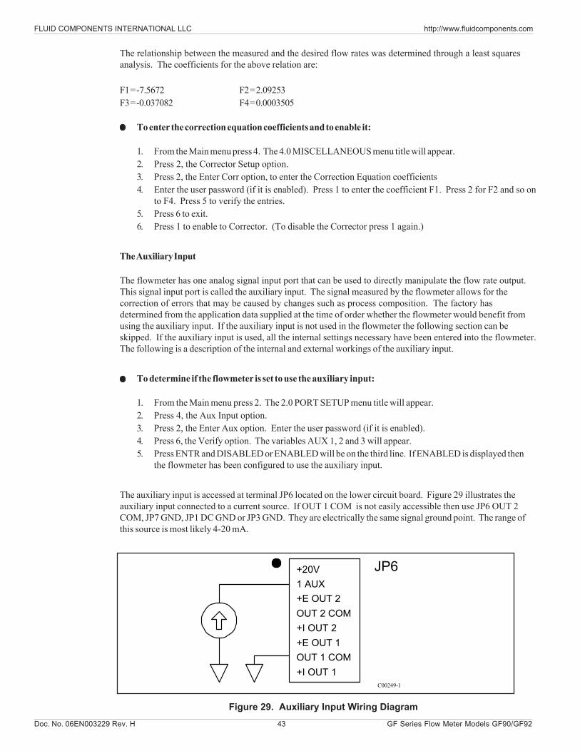
Doc. No. 06EN003229 Rev. H 43 GF Series Flow Meter Models GF90/GF92
FLUID COMPONENTS INTERNATIONAL LLC http://www.fluidcomponents.com
The relationship between the measured and the desired flow rates was determined through a least squaresanalysis. The coefficients for the above relation are:
F1 = -7.5672 F2 = 2.09253F3 = -0.037082 F4 = 0.0003505
To enter the correction equation coefficients and to enable it:
1. From the Main menu press 4. The 4.0 MISCELLANEOUS menu title will appear.2. Press 2, the Corrector Setup option.3. Press 2, the Enter Corr option, to enter the Correction Equation coefficients4. Enter the user password (if it is enabled). Press 1 to enter the coefficient F1. Press 2 for F2 and so on
to F4. Press 5 to verify the entries.5. Press 6 to exit.6. Press 1 to enable to Corrector. (To disable the Corrector press 1 again.)
The Auxiliary Input
The flowmeter has one analog signal input port that can be used to directly manipulate the flow rate output.This signal input port is called the auxiliary input. The signal measured by the flowmeter allows for thecorrection of errors that may be caused by changes such as process composition. The factory hasdetermined from the application data supplied at the time of order whether the flowmeter would benefit fromusing the auxiliary input. If the auxiliary input is not used in the flowmeter the following section can beskipped. If the auxiliary input is used, all the internal settings necessary have been entered into the flowmeter.The following is a description of the internal and external workings of the auxiliary input.
To determine if the flowmeter is set to use the auxiliary input:
1. From the Main menu press 2. The 2.0 PORT SETUP menu title will appear.2. Press 4, the Aux Input option.3. Press 2, the Enter Aux option. Enter the user password (if it is enabled).4. Press 6, the Verify option. The variables AUX 1, 2 and 3 will appear.5. Press ENTR and DISABLED or ENABLED will be on the third line. If ENABLED is displayed then
the flowmeter has been configured to use the auxiliary input.
The auxiliary input is accessed at terminal JP6 located on the lower circuit board. Figure 29 illustrates theauxiliary input connected to a current source. If OUT 1 COM is not easily accessible then use JP6 OUT 2COM, JP7 GND, JP1 DC GND or JP3 GND. They are electrically the same signal ground point. The range ofthis source is most likely 4-20 mA.
+20V1 AUX+E OUT 2OUT 2 COM+I OUT 2+E OUT 1OUT 1 COM+I OUT 1
JP6
C00249-1
Figure 29. Auxiliary Input Wiring Diagram
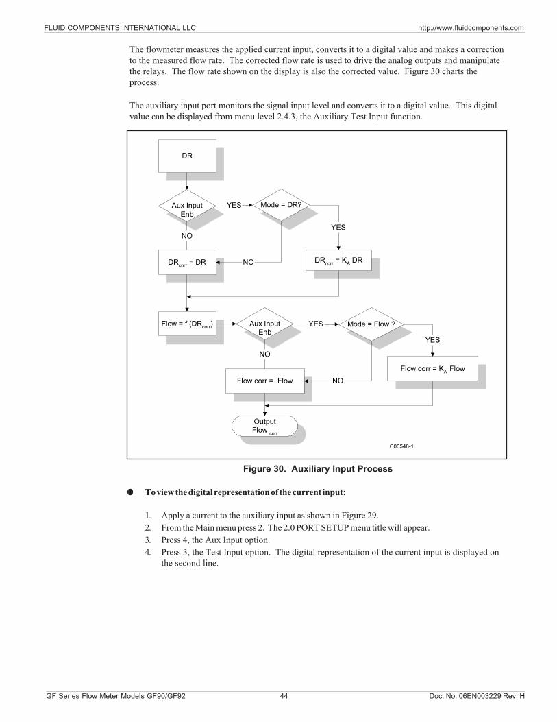
FLUID COMPONENTS INTERNATIONAL LLC http://www.fluidcomponents.com
GF Series Flow Meter Models GF90/GF92 44 Doc. No. 06EN003229 Rev. H
The flowmeter measures the applied current input, converts it to a digital value and makes a correctionto the measured flow rate. The corrected flow rate is used to drive the analog outputs and manipulatethe relays. The flow rate shown on the display is also the corrected value. Figure 30 charts theprocess.
The auxiliary input port monitors the signal input level and converts it to a digital value. This digitalvalue can be displayed from menu level 2.4.3, the Auxiliary Test Input function.
Figure 30. Auxiliary Input Process
To view the digital representation of the current input:
1. Apply a current to the auxiliary input as shown in Figure 29.2. From the Main menu press 2. The 2.0 PORT SETUP menu title will appear.3. Press 4, the Aux Input option.4. Press 3, the Test Input option. The digital representation of the current input is displayed on
the second line.
DR
Aux InputEnb
Mode = DR?
DRcorr = DR DRcorr = KA DR
Flow = f (DRcorr) Aux InputEnb
Mode = Flow ?
Flow corr = FlowFlow corr = KA Flow
YES
NO
NO
YES
YES
YES
NO
C00548-1
OutputFlow corr
NO
Doc. No. 06EN003229 Rev. H 45 GF Series Flow Meter Models GF90/GF92
FLUID COMPONENTS INTERNATIONAL LLC http://www.fluidcomponents.com
Serial Communications
Make the electrical connections using the infomation from the last chapter. The wiring diagram is Figure 8.The data stream is sent at a rate of 9600 baud with no parity, 8 bit characters and 1 stop bit. The baud rate isfixed and cannot be changed. All operations accessible through the keypad are also available through theserial port, JP3 located on the lower right corner of the upper circuit board. The serial port input/outputstream duplicates the actions of the keypad and the LCD display. Commands sent through the serial port tomanipulate the flowmeter are exactly equivalent to the keypad sequences. Data coming out of the serial portis equivalent to the data sent to the display. Remote communication with the flowmeter consists of charactersequences that duplicate actions taken at the keypad. For example, the string H 2 4 2 5 produces the sameresults as pressing HOME, 2, 4, 2, 5 from the keypad. Figure 31A is an example of code written in Quick Basicthat extracts the flow rate and the temperature through the serial port.
A common communication problem is over writing flowmeter serial buffer. If the buffer is overwritten the lastcharacters sent are lost. If the flowmeter does not respond as expected to a command, slow down the dataflow from the user PC or control device.
The approximate relationship between current input and the digital value displayed in menu level 2.4.3 is:
Digital Value = Current Input x 51.1
The digital value is used to manipulate the measured flow rate or the TCdR value. This digital value is used tocalculate a factor that is multiplied by the measured flow rate or TCdR. The factor is calculated using therelationship:KA = A1 + (A2 x s) + (A3 s
2) + (A4 x s3)where s = Digital Value
Ai = Correction Factor Coefficients ( i = 1 through 4 )KA = Correction Factor
NOTE: Ai is used for clarity in the manual. The flowmeter uses Fj as the Correction Factor Coefficient.
The Auxiliary Input Equation coefficients are determined by the factory from the data supplied at the time oforder entry.
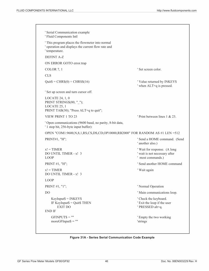
FLUID COMPONENTS INTERNATIONAL LLC http://www.fluidcomponents.com
GF Series Flow Meter Models GF90/GF92 46 Doc. No. 06EN003229 Rev. H
' Serial Communication example' Fluid Components Intl
' This program places the flowmeter into normal' operation and displays the current flow rate and' temperature.
DEFINT A-Z
ON ERROR GOTO error.trap
COLOR 7, 1 ' Set screen color.
CLS
Quit$ = CHR$(0) + CHRS$(16) ' Value returned by INKEY$' when ALT+q is pressed.
' Set up screen and turn cursor off.
LOCATE 24, 1, 0PRINT STRING$(80, "_");LOCATE 25, 1PRINT TAB(30); "Press ALT+q to quit";
VIEW PRINT 1 TO 23 ' Print between lines 1 & 23.
' Open communications (9600 baud, no parity, 8-bit data,' 1 stop bit, 256-byte input buffer):
OPEN "COM1:9600,N,8,1,RS,CS,DS,CD,OP10000,RB2000" FOR RANDOM AS #1 LEN =512
PRINT#1, "H"; ' Send a HOME command. (Send' another also.)
x! = TIMER ' Wait for response. (A longDO UNTIL TIMER - x! 3 ' wait is not necessary afterLOOP ' most commands.)
PRINT #1, "H"; ' Send another HOME command
x! = TIMER ' Wait againDO UNTIL TIMER - x! 3
LOOP
PRINT #1, "1"; ' Normal Operation
DO ' Main communications loop.
KeyInput$ = INKEY$ ' Check the keyboard.IF KeyInput$ = Quit$ THEN ' Exit the loop if the user EXIT DO ' PRESSED alt+q.
END IF
GFINPUT$ = "" ' Empty the two workingmoreGFInput$ = "" 'strings
Figure 31A - Series Serial Communication Code Example
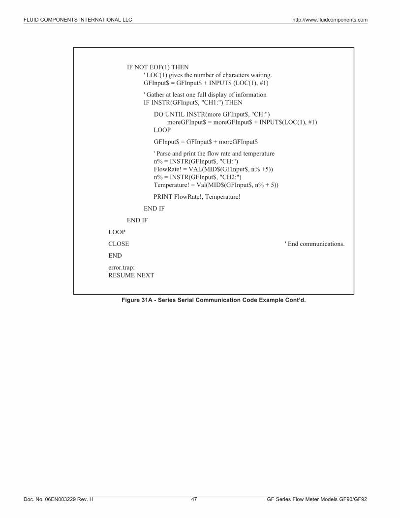
Doc. No. 06EN003229 Rev. H 47 GF Series Flow Meter Models GF90/GF92
FLUID COMPONENTS INTERNATIONAL LLC http://www.fluidcomponents.com
IF NOT EOF(1) THEN' LOC(1) gives the number of characters waiting.GFInput$ = GFInput$ + INPUT$ (LOC(1), #1)
' Gather at least one full display of informationIF INSTR(GFInput$, "CH1:") THEN
DO UNTIL INSTR(more GFInput$, "CH:")moreGFInput$ = moreGFInput$ + INPUT$(LOC(1), #1)
LOOP
GFInput$ = GFInput$ + moreGFInput$
' Parse and print the flow rate and temperature n% = INSTR(GFInput$, "CH:") FlowRate! = VAL(MID$(GFInput$, n% +5)) n% = INSTR(GFInput$, "CH2:") Temperature! = Val(MID$(GFInput$, n% + 5))
PRINT FlowRate!, Temperature!
END IF
END IF
LOOP
CLOSE ' End communications.
END
error.trap:RESUME NEXT
Figure 31A - Series Serial Communication Code Example Cont’d.
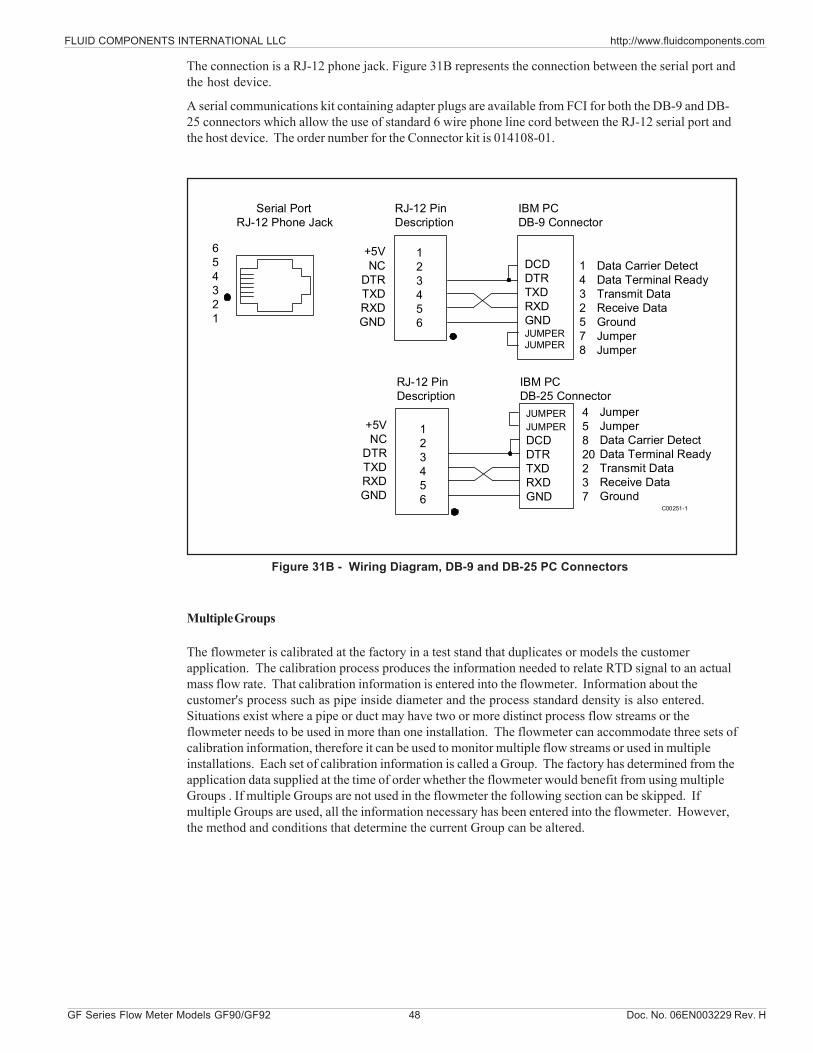
FLUID COMPONENTS INTERNATIONAL LLC http://www.fluidcomponents.com
GF Series Flow Meter Models GF90/GF92 48 Doc. No. 06EN003229 Rev. H
The connection is a RJ-12 phone jack. Figure 31B represents the connection between the serial port andthe host device.
A serial communications kit containing adapter plugs are available from FCI for both the DB-9 and DB-25 connectors which allow the use of standard 6 wire phone line cord between the RJ-12 serial port andthe host device. The order number for the Connector kit is 014108-01.
Figure 31B - Wiring Diagram, DB-9 and DB-25 PC Connectors
Multiple Groups
The flowmeter is calibrated at the factory in a test stand that duplicates or models the customerapplication. The calibration process produces the information needed to relate RTD signal to an actualmass flow rate. That calibration information is entered into the flowmeter. Information about thecustomer's process such as pipe inside diameter and the process standard density is also entered.Situations exist where a pipe or duct may have two or more distinct process flow streams or theflowmeter needs to be used in more than one installation. The flowmeter can accommodate three sets ofcalibration information, therefore it can be used to monitor multiple flow streams or used in multipleinstallations. Each set of calibration information is called a Group. The factory has determined from theapplication data supplied at the time of order whether the flowmeter would benefit from using multipleGroups . If multiple Groups are not used in the flowmeter the following section can be skipped. Ifmultiple Groups are used, all the information necessary has been entered into the flowmeter. However,the method and conditions that determine the current Group can be altered.
654321
Serial PortRJ-12 Phone Jack
123456
RJ-12 PinDescription
DCDDTRTXDRXDGNDJUMPERJUMPER
IBM PCDB-9 Connector
Data Carrier DetectData Terminal ReadyTransmit DataReceive DataGroundJumperJumper
+5VNC
DTRTXDRXDGND
123456
RJ-12 PinDescription
JUMPERJUMPERDCDDTRTXDRXDGND
IBM PCDB-25 Connector
JumperJumperData Carrier DetectData Terminal ReadyTransmit DataReceive DataGround
+5VNC
DTRTXDRXDGND
45820237
1432578
C00251-1
Doc. No. 06EN003229 Rev. H 49 GF Series Flow Meter Models GF90/GF92
FLUID COMPONENTS INTERNATIONAL LLC http://www.fluidcomponents.com
To determine if the flowmeter is set to use the Multiple Groups:
From the Main menu press 1. The flowmeter will enter the normal mode of operation. If the mode on thelast line of the window (see Figure 16) is Auto, or Link then the flowmeter contains multiple calibrationgroups.If the mode is normal or Norm is displayed in the normal operation window, the flowmeter may stillcontain multiple calibration groups.
To determine if the flowmeter is set to use the Multiple Groups in Normal mode:
1. Press 4, the Miscellaneous option.2. Press 1, the Set Group option.3. Press 1 again, the Set Group option. Enter the user password (if it is enabled).4. Press 2, to change the current group to Group 2.5. Press HOME, 7, 3 and 8. Scroll the display to show C1 to C5. If the coefficients C1 through C5 are
non-zero values, the Flowmeter has been set to use multiple groups.6. Change the current group in Set Group back to group 1.
Switching Groups Through the Keypad
The current calibration group that the flowmeter uses can be changed from the keypad. This may be themost desirable method of changing groups for a flowmeter that has been configured for multipleinstallations.
To change the current group from the keypad:
1. Press 4, the Set Group option.2. Press 1, the Set Group option. Enter the user password (if it is enabled).3. Enter the desired group number, 1, 2 or 3. The flowmeter is now set to use that group of calibration
information.
Switching Groups Through the Serial Port
The current calibration group can be changed remotely through the serial port. The sequence of commandssent through the serial port is equivalent to the sequence taken at the keypad. The command string shouldinclude sufficient time delays to allow the flowmeter to respond. One possible command string is "H H 4 1 1"+ (desired group number) + "H 1". The command string sends to HOME (H) characters, sets the menu levelto 4.1.1, enters the desired group number and returns the flowmeter to normal operation. Remember to inserta time delay after sending each character. (See Figure 31A for an serial communication example.)
Switching Groups by Temperature - Auto-Selecting
The flowmeter has the ability to switch groups on changes in process temperature or changes in signal intothe auxiliary port. To use the auto-select option, the flowmeter must be configured by the factory. Use theprocedure described in the section Multiple Groups to determine if the flowmeter has been configured to usemultiple groups. In Auto-Select mode the user can program the flowmeter to switch on temperature. Onetemperature switch point is used for switching between two groups and two switch points are used for threegroups. The switch points have a 2.5% hysteresis and cannot be changed. A typical application that wouldbenefit from using auto-selecting by temperature is described in Figure 32.
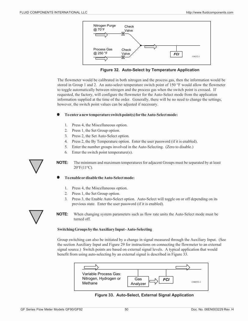
FLUID COMPONENTS INTERNATIONAL LLC http://www.fluidcomponents.com
GF Series Flow Meter Models GF90/GF92 50 Doc. No. 06EN003229 Rev. H
The flowmeter would be calibrated in both nitrogen and the process gas, then the information would bestored in Group 1 and 2. An auto-select temperature switch point of 150 °F would allow the flowmeterto toggle automatically between nitrogen and the process gas when the switch point is crossed. Ifrequested, the factory, will configure the flowmeter for the Auto-Select mode from the applicationinformation supplied at the time of the order. Generally, there will be no need to change the settings,however, the switch point values can be adjusted if necessary.
To enter a new temperature switch point(s) for the Auto-Select mode:
1. Press 4, the Miscellaneous option.2. Press 1, the Set Group option.3. Press 2, the Set Auto-Select option.4. Press 2, the By Temperature option. Enter the user password (if it is enabled).5. Enter the number groups involved in the Auto-Selecting. (Zero to disable.)6. Enter the switch point temperature(s).
NOTE: The minimum and maximum temperatures for adjacent Groups must be separated by at least20°F (11°C).
To enable or disable the Auto-Select mode:
1. Press 4, the Miscellaneous option.2. Press 1, the Set Group option.3. Press 3, the Enable Auto-Select option. Auto-Select will toggle on or off depending on its
previous state. Enter the user password (if it is enabled).
NOTE: When changing system parameters such as flow rate units the Auto-Select mode must beturned off.
Switching Groups by the Auxiliary Input - Auto-Selecting
Group switching can also be initiated by a change in signal measured through the Auxiliary Input. (Seethe section Auxiliary Input and Figure 29 for instructions on connecting the flowmeter to an externalsignal source.) Switch points are based on external signal levels. A typical application that wouldbenefit from using auto-selecting by an external signal is described in Figure 33.
FCI
Nitrogen Purge@ 70°F
CheckValve
CheckValve
Process Gas@ 250 °F
C00252-1
Figure 32. Auto-Select by Temperature Application
Figure 33. Auto-Select, External Signal Application
FCIVariable Process Gas:Nitrogen, Hydrogen orMethane
GasAnalyzer C00253-1
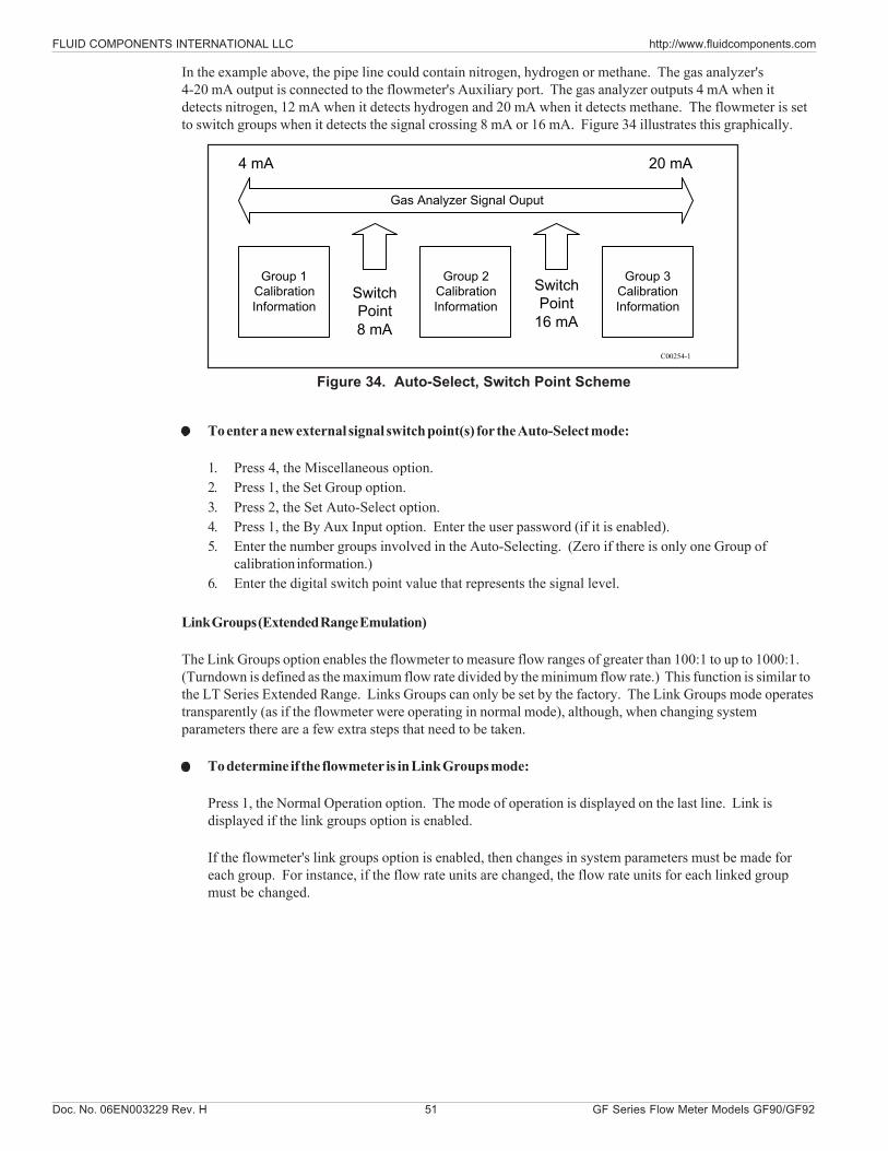
Doc. No. 06EN003229 Rev. H 51 GF Series Flow Meter Models GF90/GF92
FLUID COMPONENTS INTERNATIONAL LLC http://www.fluidcomponents.com
In the example above, the pipe line could contain nitrogen, hydrogen or methane. The gas analyzer's4-20 mA output is connected to the flowmeter's Auxiliary port. The gas analyzer outputs 4 mA when itdetects nitrogen, 12 mA when it detects hydrogen and 20 mA when it detects methane. The flowmeter is setto switch groups when it detects the signal crossing 8 mA or 16 mA. Figure 34 illustrates this graphically.
To enter a new external signal switch point(s) for the Auto-Select mode:
1. Press 4, the Miscellaneous option.2. Press 1, the Set Group option.3. Press 2, the Set Auto-Select option.4. Press 1, the By Aux Input option. Enter the user password (if it is enabled).5. Enter the number groups involved in the Auto-Selecting. (Zero if there is only one Group of
calibration information.)6. Enter the digital switch point value that represents the signal level.
Link Groups (Extended Range Emulation)
The Link Groups option enables the flowmeter to measure flow ranges of greater than 100:1 to up to 1000:1.(Turndown is defined as the maximum flow rate divided by the minimum flow rate.) This function is similar tothe LT Series Extended Range. Links Groups can only be set by the factory. The Link Groups mode operatestransparently (as if the flowmeter were operating in normal mode), although, when changing systemparameters there are a few extra steps that need to be taken.
To determine if the flowmeter is in Link Groups mode:
Press 1, the Normal Operation option. The mode of operation is displayed on the last line. Link isdisplayed if the link groups option is enabled.
If the flowmeter's link groups option is enabled, then changes in system parameters must be made foreach group. For instance, if the flow rate units are changed, the flow rate units for each linked groupmust be changed.
Group 1CalibrationInformation
Group 2CalibrationInformation
Group 3CalibrationInformation
Gas Analyzer Signal Ouput
4 mA 20 mA
SwitchPoint8 mA
SwitchPoint
16 mA
C00254-1
Figure 34. Auto-Select, Switch Point Scheme
FLUID COMPONENTS INTERNATIONAL LLC http://www.fluidcomponents.com
GF Series Flow Meter Models GF90/GF92 52 Doc. No. 06EN003229 Rev. H
To change system parameters in Link Groups mode:
Contact factory to change system parameters in link mode.
NOTE: The link groups (extended range) and auto-select modes cannot be used simultaneously.Calibration Functions, Menu 7.0
The calibration functions of the flowmeter are contained in menu level 7.0. These functions are notneeded for general operation and setup of the flowmeter. With the exception of 7.1, Show Delta R, thesefunctions should be used only after consultation with a factory service representative. Menu level 7.1displays the RTD resistances and can be compared to calibration resistances. This is useful fortroubleshooting problems and is addressed in Chapter 6, Troubleshooting.
To view RTD resistance values:
1. Press 7, the Calibration option.2. Press 1, the Show Delta R option.3. Press 1, for raw dR, 2 for TCdR or 3 for AIdR
Forced Output Setup (EPROM Version 4.20 and later)PurposeTo force the analog output of the unit.
PasswordThe user password is required to perform this procedure.
ProcedureGo to the ‘Set Output’ menu by pressing 8, 3, 2. Select the output port you wish to test, either 1 or 2.Select the percentage of full scale for the output, 0% = 4mA and 100% = 20mA.
To change the forced output, press N for ‘New Value’ or to Exit, press Home.
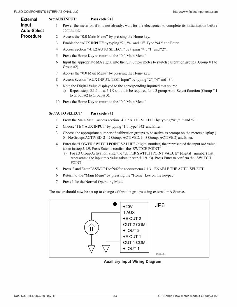
Doc. No. 06EN003229 Rev. H 53 GF Series Flow Meter Models GF90/GF92
FLUID COMPONENTS INTERNATIONAL LLC http://www.fluidcomponents.com
Set ‘AUX INPUT’ Pass code 9421. Power the meter on if it is not already; wait for the electronics to complete its initialization before
continuing.
2. Access the “0.0 Main Menu” by pressing the Home key.
3. Enable the “AUX INPUT” by typing “2”, “4” and “1”. Type ‘942’ and Enter4. Access Section “ 4.1.2 AUTO SELECT” by typing “4”, “1” and “2”.
5. Press the Home Key to return to the “0.0 Main Menu”
6. Input the appropriate MA signal into the GF90 flow meter to switch calibration groups (Group # 1 toGroup #2)
7. Access the “0.0 Main Menu” by pressing the Home key.8. Access Section “AUX INPUT, TEST Input” by typing “2”, “4” and “3”.
9. Note the Digital Value displayed to the corresponding inputted mA source.a) Repeat steps 5.1.5 thru. 5.1.9 should it be required for a 3 group Auto-Select function (Group # 1
to Group #2 to Group # 3).
10. Press the Home Key to return to the “0.0 Main Menu”
Set ‘AUTO SELECT’ Pass code 942
1. From the Main Menu, access section “4.1.2 AUTO SELECT by typing “4”, “1” and “2”
2. Choose ‘1 BY AUX INPUT’ by typing “1”. Type ‘942’ and Enter.
3. Choose the appropriate number of calibration groups to be active as prompt on the meters display (0 = No Groups ACTIVED, 2 = 2 Groups ACTIVED, 3= 3 Groups ACTIVED) and Enter.
4. Enter the “LOWER SWITCH POINT VALUE” (digital number) that represented the input mA valuetaken in step 5.1.9. Press Enter to confirm the ‘SWITCH POINT’a) For a 3 Group Activation, enter the “UPPER SWITCH POINT VALUE” (digital number) that
represented the input mA value taken in step 5.1.9. a)). Press Enter to confirm the ‘SWITCHPOINT’
5. Press ‘3 and Enter PASWORD of 942’ to access menu 4.1.3. “ENABLE THE AUTO-SELECT”
6. Return to the “Main Menu” by pressing the “Home” key on the keypad.
7. Press 1 for the Normal Operating Mode
The meter should now be set up to change calibration groups using external mA Source.
ExternalInputAuto-SelectProcedure
+20V1 AUX+E OUT 2OUT 2 COM+I OUT 2+E OUT 1OUT 1 COM+I OUT 1
JP6
C00249-1
Auxiliary Input Wiring Diagram
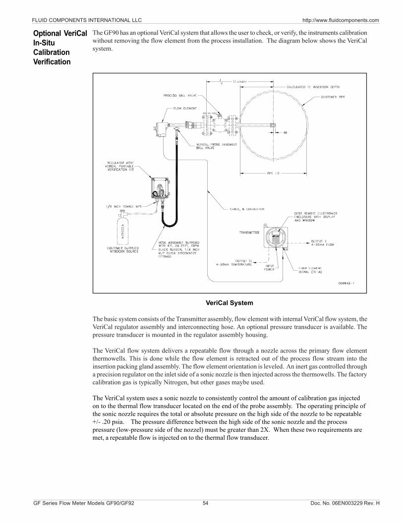
FLUID COMPONENTS INTERNATIONAL LLC http://www.fluidcomponents.com
GF Series Flow Meter Models GF90/GF92 54 Doc. No. 06EN003229 Rev. H
The GF90 has an optional VeriCal system that allows the user to check, or verify, the instruments calibrationwithout removing the flow element from the process installation. The diagram below shows the VeriCalsystem.
VeriCal System
The basic system consists of the Transmitter assembly, flow element with internal VeriCal flow system, theVeriCal regulator assembly and interconnecting hose. An optional pressure transducer is available. Thepressure transducer is mounted in the regulator assembly housing.
The VeriCal flow system delivers a repeatable flow through a nozzle across the primary flow elementthermowells. This is done while the flow element is retracted out of the process flow stream into theinsertion packing gland assembly. The flow element orientation is leveled. An inert gas controlled througha precision regulator on the inlet side of a sonic nozzle is then injected across the thermowells. The factorycalibration gas is typically Nitrogen, but other gases maybe used.
The VeriCal system uses a sonic nozzle to consistently control the amount of calibration gas injectedon to the thermal flow transducer located on the end of the probe assembly. The operating principle ofthe sonic nozzle requires the total or absolute pressure on the high side of the nozzle to be repeatable+/- .20 psia. The pressure difference between the high side of the sonic nozzle and the processpressure (low-pressure side of the nozzel) must be greater than 2X. When these two requirements aremet, a repeatable flow is injected on to the thermal flow transducer.
Optional VeriCalIn-SituCalibrationVerification
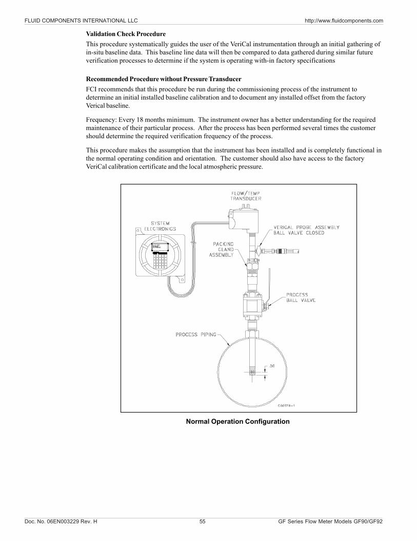
Doc. No. 06EN003229 Rev. H 55 GF Series Flow Meter Models GF90/GF92
FLUID COMPONENTS INTERNATIONAL LLC http://www.fluidcomponents.com
Validation Check ProcedureThis procedure systematically guides the user of the VeriCal instrumentation through an initial gathering ofin-situ baseline data. This baseline line data will then be compared to data gathered during similar futureverification processes to determine if the system is operating with-in factory specifications
Recommended Procedure without Pressure TransducerFCI recommends that this procedure be run during the commissioning process of the instrument todetermine an initial installed baseline calibration and to document any installed offset from the factoryVerical baseline.
Frequency: Every 18 months minimum. The instrument owner has a better understanding for the requiredmaintenance of their particular process. After the process has been performed several times the customershould determine the required verification frequency of the process.
This procedure makes the assumption that the instrument has been installed and is completely functional inthe normal operating condition and orientation. The customer should also have access to the factoryVeriCal calibration certificate and the local atmospheric pressure.
Normal Operation Configuration
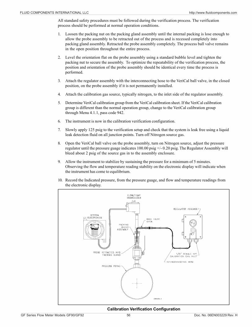
FLUID COMPONENTS INTERNATIONAL LLC http://www.fluidcomponents.com
GF Series Flow Meter Models GF90/GF92 56 Doc. No. 06EN003229 Rev. H
All standard safety procedures must be followed during the verification process. The verificationprocess should be performed at normal operation conditions.
1. Loosen the packing nut on the packing gland assembly until the internal packing is lose enough toallow the probe assembly to be retracted out of the process and is recessed completely intopacking gland assembly. Retracted the probe assembly completely. The process ball valve remainsin the open position throughout the entire process.
2. Level the orientation flat on the probe assembly using a standard bubble level and tighten thepacking nut to secure the assembly. To optimize the repeatability of the verification process, theposition and orientation of the probe assembly should be identical every time the process isperformed.
3. Attach the regulator assembly with the interconnecting hose to the VeriCal ball valve, in the closedposition, on the probe assembly if it is not permanently installed.
4. Attach the calibration gas source, typically nitrogen, to the inlet side of the regulator assembly.
5. Determine VeriCal calibration group from the VeriCal calibration sheet. If the VeriCal calibrationgroup is different than the normal operation group, change to the VeriCal calibration groupthrough Menu 4.1.1, pass code 942.
6. The instrument is now in the calibration verification configuration.
7. Slowly apply 125 psig to the verification setup and check that the system is leak free using a liquidleak detection fluid on all junction points. Turn off Nitrogen source gas.
8. Open the VeriCal ball valve on the probe assembly, turn on Nitrogen source, adjust the pressureregulator until the pressure guage indicates 100.00 psig +/- 0.20 psig. The Regulator Assembly willbleed about 2 psig of the source gas in to the assembly enclosure.
9. Allow the instrument to stabilize by sustaining the pressure for a minimum of 5 minutes.Observing the flow and temperature reading stability on the electronic display will indicate whenthe instrument has come to equilibrium.
10. Record the Indicated pressure, from the pressure guage, and flow and temperature readings fromthe electronic display.
Calibration Verification Configuration
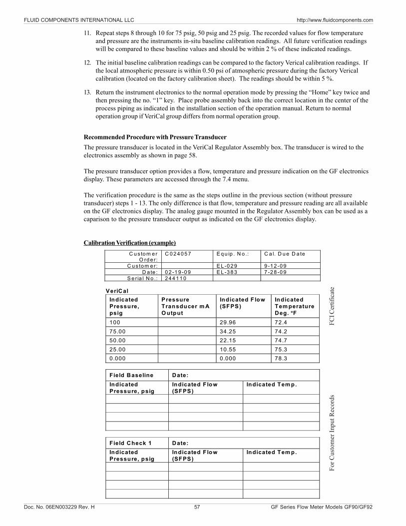
Doc. No. 06EN003229 Rev. H 57 GF Series Flow Meter Models GF90/GF92
FLUID COMPONENTS INTERNATIONAL LLC http://www.fluidcomponents.com
11. Repeat steps 8 through 10 for 75 psig, 50 psig and 25 psig. The recorded values for flow temperatureand pressure are the instruments in-situ baseline calibration readings. All future verification readingswill be compared to these baseline values and should be within 2 % of these indicated readings.
12. The initial baseline calibration readings can be compared to the factory Verical calibration readings. Ifthe local atmospheric pressure is within 0.50 psi of atmospheric pressure during the factory Vericalcalibration (located on the factory calibration sheet). The readings should be within 5 %.
13. Return the instrument electronics to the normal operation mode by pressing the “Home” key twice andthen pressing the no. “1” key. Place probe assembly back into the correct location in the center of theprocess piping as indicated in the installation section of the operation manual. Return to normaloperation group if VeriCal group differs from normal operation group.
Calibration Verification (example)
C u s to m e r O rd e r:
C 0 2 4 0 5 7 E q u ip . N o .: C a l. D u e D a te
C u s to m e r: E L -0 2 9 9 -1 2 -0 9 D a te : 0 2 -1 9 -0 9 E L -3 8 3 7 -2 8 -0 9
S e ria l N o .: 2 4 4 1 1 0
VeriCal Indicated Pressure, psig
Pressure Transducer m A O utput
Indicated F low (SFPS)
Indicated Tem perature Deg. F
100 29.96 72.4 75.00 34.25 74.2 50.00 22.15 74.7 25.00 10.55 75.3 0.000 0.000 78.3
Field Baseline Date: Indicated Pressure, psig
Indicated F low (SFPS)
Indicated Tem p.
Field Check 1 Date: Indicated Pressure, psig
Indicated F low (SFPS)
Indicated Tem p.
Recommended Procedure with Pressure TransducerThe pressure transducer is located in the VeriCal Regulator Assembly box. The transducer is wired to theelectronics assembly as shown in page 58.
The pressure transducer option provides a flow, temperature and pressure indication on the GF electronicsdisplay. These parameters are accessed through the 7.4 menu.
The verification procedure is the same as the steps outline in the previous section (without pressuretransducer) steps 1 - 13. The only difference is that flow, temperature and pressure reading are all availableon the GF electronics display. The analog gauge mounted in the Regulator Assembly box can be used as acaparison to the pressure transducer output as indicated on the GF electronics display.
FCI C
ertif
icat
eFo
r Cus
tom
er In
put R
ecor
ds
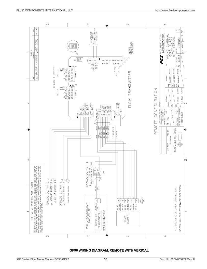
FLUID COMPONENTS INTERNATIONAL LLC http://www.fluidcomponents.com
GF Series Flow Meter Models GF90/GF92 58 Doc. No. 06EN003229 Rev. H
GF90 WIRING DIAGRAM, REMOTE WITH VERICAL
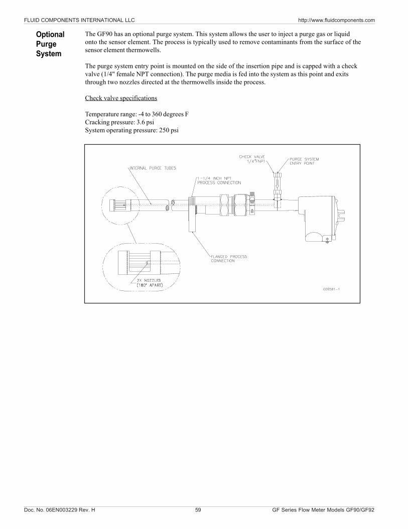
Doc. No. 06EN003229 Rev. H 59 GF Series Flow Meter Models GF90/GF92
FLUID COMPONENTS INTERNATIONAL LLC http://www.fluidcomponents.com
The GF90 has an optional purge system. This system allows the user to inject a purge gas or liquidonto the sensor element. The process is typically used to remove contaminants from the surface of thesensor element thermowells.
The purge system entry point is mounted on the side of the insertion pipe and is capped with a checkvalve (1/4" female NPT connection). The purge media is fed into the system as this point and exitsthrough two nozzles directed at the thermowells inside the process.
Check valve specifications
Temperature range: -4 to 360 degrees FCracking pressure: 3.6 psiSystem operating pressure: 250 psi
OptionalPurgeSystem
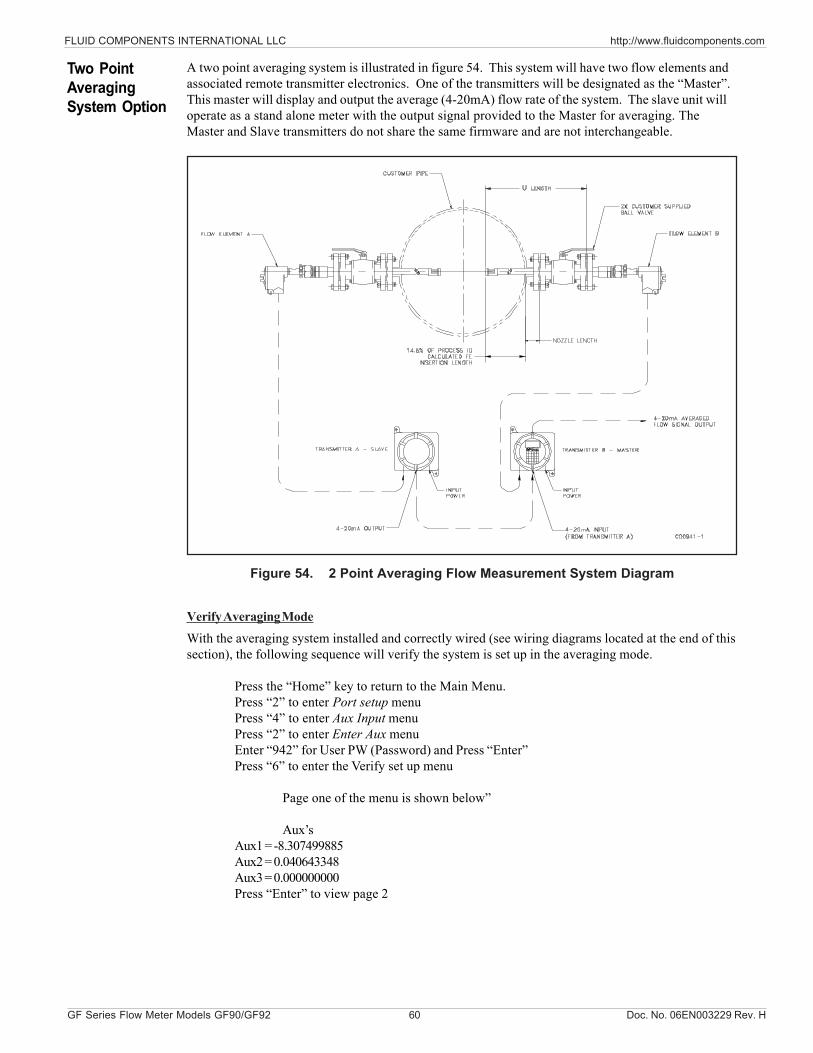
FLUID COMPONENTS INTERNATIONAL LLC http://www.fluidcomponents.com
GF Series Flow Meter Models GF90/GF92 60 Doc. No. 06EN003229 Rev. H
A two point averaging system is illustrated in figure 54. This system will have two flow elements andassociated remote transmitter electronics. One of the transmitters will be designated as the “Master”.This master will display and output the average (4-20mA) flow rate of the system. The slave unit willoperate as a stand alone meter with the output signal provided to the Master for averaging. TheMaster and Slave transmitters do not share the same firmware and are not interchangeable.
Figure 54. 2 Point Averaging Flow Measurement System Diagram
Two PointAveragingSystem Option
Verify Averaging ModeWith the averaging system installed and correctly wired (see wiring diagrams located at the end of thissection), the following sequence will verify the system is set up in the averaging mode.
Press the “Home” key to return to the Main Menu.Press “2” to enter Port setup menuPress “4” to enter Aux Input menuPress “2” to enter Enter Aux menuEnter “942” for User PW (Password) and Press “Enter”Press “6” to enter the Verify set up menu
Page one of the menu is shown below”
Aux’sAux1 = -8.307499885Aux2 = 0.040643348Aux3 = 0.000000000Press “Enter” to view page 2
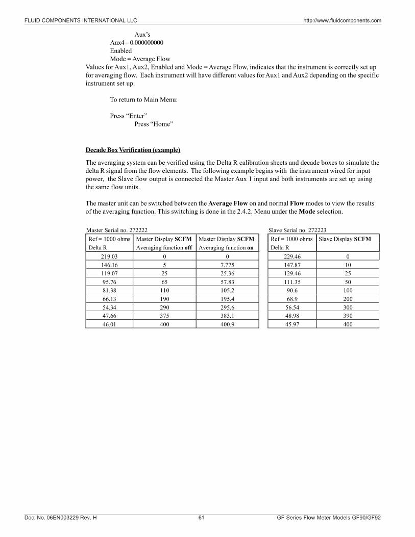
Doc. No. 06EN003229 Rev. H 61 GF Series Flow Meter Models GF90/GF92
FLUID COMPONENTS INTERNATIONAL LLC http://www.fluidcomponents.com
Decade Box Verification (example)
The averaging system can be verified using the Delta R calibration sheets and decade boxes to simulate thedelta R signal from the flow elements. The following example begins with the instrument wired for inputpower, the Slave flow output is connected the Master Aux 1 input and both instruments are set up usingthe same flow units.
The master unit can be switched between the Average Flow on and normal Flow modes to view the resultsof the averaging function. This switching is done in the 2.4.2. Menu under the Mode selection.
Master Serial no. 272222 Slave Serial no. 272223 Ref = 1000 ohms Master Display SCFM Master Display SCFM Ref = 1000 ohms Slave Display SCFM Delta R Averaging function off Averaging function on Delta R
219.03 0 0 229.46 0 146.16 5 7.775 147.87 10 119.07 25 25.36 129.46 25 95.76 65 57.83 111.35 50 81.38 110 105.2 90.6 100 66.13 190 195.4 68.9 200 54.34 290 295.6 56.54 300 47.66 375 383.1 48.98 390 46.01 400 400.9 45.97 400
Aux’sAux4 = 0.000000000EnabledMode = Average Flow
Values for Aux1, Aux2, Enabled and Mode = Average Flow, indicates that the instrument is correctly set upfor averaging flow. Each instrument will have different values for Aux1 and Aux2 depending on the specificinstrument set up.
To return to Main Menu:
Press “Enter”Press “Home”
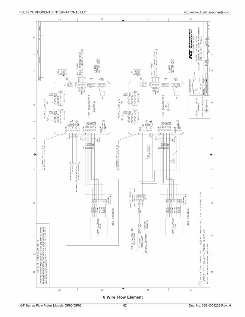
FLUID COMPONENTS INTERNATIONAL LLC http://www.fluidcomponents.com
GF Series Flow Meter Models GF90/GF92 62 Doc. No. 06EN003229 Rev. H
8 Wire Flow Element
INTE
RN
ATIO
NA
L L
LC
FLU
ID C
OM
PO
NE
NTS
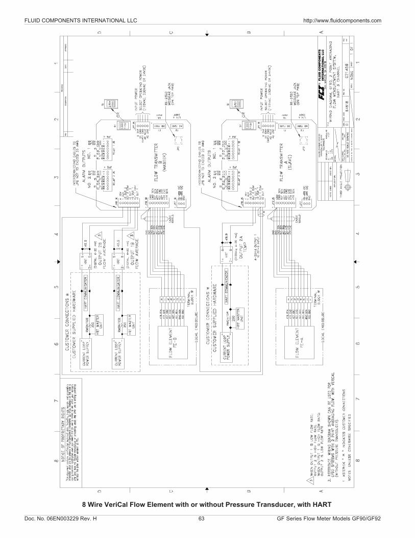
Doc. No. 06EN003229 Rev. H 63 GF Series Flow Meter Models GF90/GF92
FLUID COMPONENTS INTERNATIONAL LLC http://www.fluidcomponents.com
8 Wire VeriCal Flow Element with or without Pressure Transducer, with HART
INT
ER
NA
TIO
NA
L L
LC
FLU
ID C
OM
PO
NE
NTS
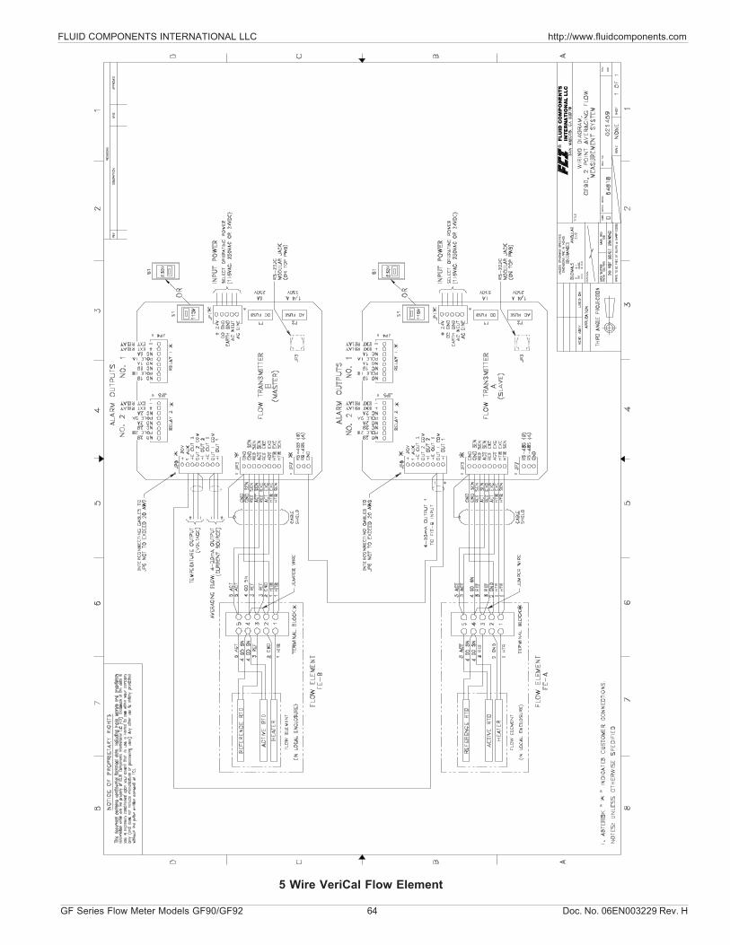
FLUID COMPONENTS INTERNATIONAL LLC http://www.fluidcomponents.com
GF Series Flow Meter Models GF90/GF92 64 Doc. No. 06EN003229 Rev. H
INTE
RN
ATIO
NA
L L
LC
FLU
ID C
OM
PO
NE
NTS
5 Wire VeriCal Flow Element
Doc. No. 06EN003229 Rev. H 65 GF Series Flow Meter Models GF90/GF92
FLUID COMPONENTS INTERNATIONAL LLC http://www.fluidcomponents.com
CAUTION: To avoid hazards to personnel, ensure that all environmental isolation seals are properlymaintained.
ALERT: The flow transmitter contains electrostatic discharge (ESD) sensitive devices. Usestandard ESD precautions when handling the flow transmitter. See Chapter 3 Installationfor ESD details.
The FCI instrument requires little maintenance. There are no moving parts or mechanical parts subjectto wear in the instrument. The sensor assembly which is exposed to the process media is all stainlesssteel construction.
Without detailed knowledge of the environmental parameters of the application surroundings andprocess media, FCI cannot make specific recommendations for periodic inspection, cleaning, or testingprocedures. However, some suggested general guidelines for maintenance steps are offered below. Useoperating experience to establish the frequency of each type of maintenance.
CalibrationPeriodically verify the calibration of the output and recalibrate if necessary. See Chapter6 - Troubleshooting. FCI recommends every 18 months at a minimum.
Electrical ConnectionsPeriodically inspect cable connections on terminal strips and terminal blocks. Verify that terminalconnections are tight and physically sound with no sign of corrosion.
Remote EnclosureVerify that the moisture barriers and seals protecting the electronics in the local and remote enclosuresare adequate and that no moisture is entering those enclosures.
Electrical WiringFCI recommends occasional inspection of the system’s interconnecting cable, power wiring and flowelement wiring on a “common sense” basis related to the application environment. Periodically theconductors should be inspected for corrosion and the cable insulation checked for signs of deterioration.
Flow Element ConnectionsVerify that all seals are performing properly and that there is no leakage of the process media. Checkfor deterioration of the gaskets and environmental seals used.
Flow Element AssemblyPeriodically remove the flow element for inspection based on historical evidence of debris, foreignmatter, or scale build-up and appropriate plant shutdown schedules and procedures. Check forcorrosion, stress cracking, and/or build-up of oxides, salts, or foreign substances. The thermowellsmust be free of excessive contaminants and be physically intact. Any debris or residue build-up couldcause inaccurate switching. Clean the flow element, as necessary, with a soft brush and availablesolvents (compatible with Stainless Steel).
5. Maintenance
Maintenance

FLUID COMPONENTS INTERNATIONAL LLC http://www.fluidcomponents.com
GF Series Flow Meter Models GF90/GF92 66 Doc. No. 06EN003229 Rev. H
THIS PAGE INTENTIONALLY LEFT BLANK
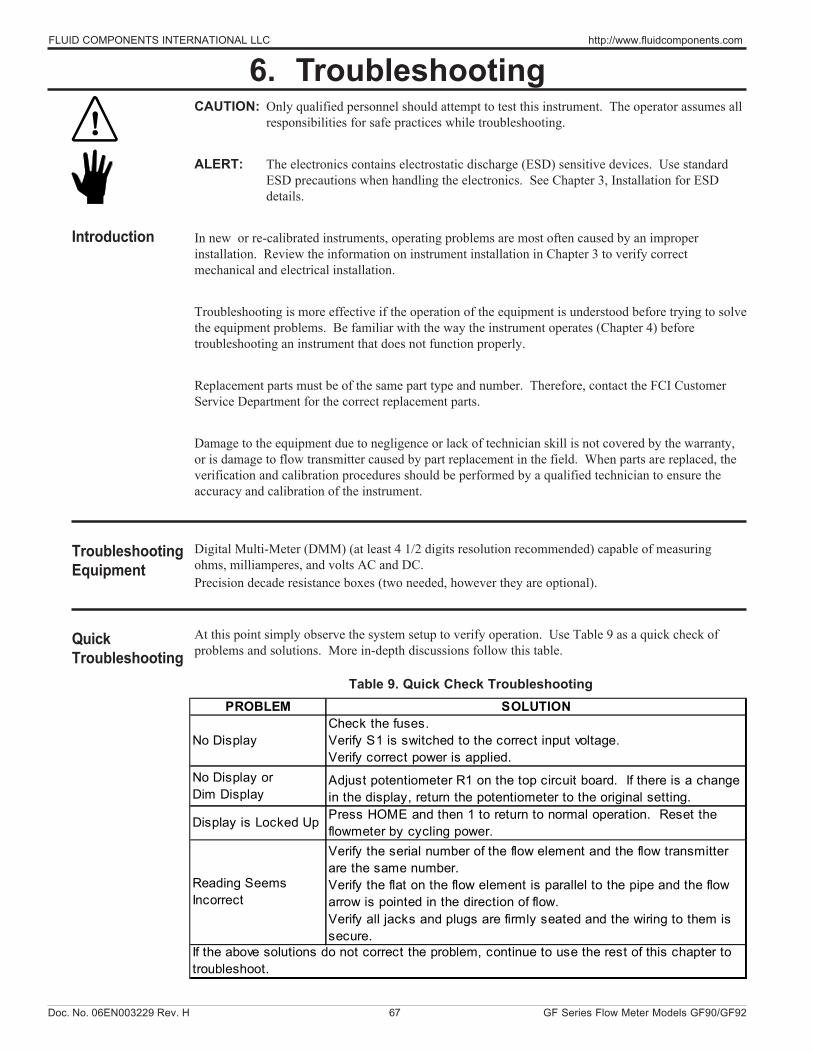
Doc. No. 06EN003229 Rev. H 67 GF Series Flow Meter Models GF90/GF92
FLUID COMPONENTS INTERNATIONAL LLC http://www.fluidcomponents.com
CAUTION: Only qualified personnel should attempt to test this instrument. The operator assumes allresponsibilities for safe practices while troubleshooting.
ALERT: The electronics contains electrostatic discharge (ESD) sensitive devices. Use standardESD precautions when handling the electronics. See Chapter 3, Installation for ESDdetails.
In new or re-calibrated instruments, operating problems are most often caused by an improperinstallation. Review the information on instrument installation in Chapter 3 to verify correctmechanical and electrical installation.
Troubleshooting is more effective if the operation of the equipment is understood before trying to solvethe equipment problems. Be familiar with the way the instrument operates (Chapter 4) beforetroubleshooting an instrument that does not function properly.
Replacement parts must be of the same part type and number. Therefore, contact the FCI CustomerService Department for the correct replacement parts.
Damage to the equipment due to negligence or lack of technician skill is not covered by the warranty,or is damage to flow transmitter caused by part replacement in the field. When parts are replaced, theverification and calibration procedures should be performed by a qualified technician to ensure theaccuracy and calibration of the instrument.
Digital Multi-Meter (DMM) (at least 4 1/2 digits resolution recommended) capable of measuringohms, milliamperes, and volts AC and DC.Precision decade resistance boxes (two needed, however they are optional).
At this point simply observe the system setup to verify operation. Use Table 9 as a quick check ofproblems and solutions. More in-depth discussions follow this table.
Table 9. Quick Check Troubleshooting
6. Troubleshooting
Introduction
TroubleshootingEquipment
QuickTroubleshooting
PROBLEM SOLUTION
No DisplayCheck the fuses. Verify S1 is switched to the correct input voltage. Verify correct power is applied.
No Display or Dim Display
Adjust potentiometer R1 on the top circuit board. If there is a change in the display, return the potentiometer to the original setting.
Display is Locked Up Press HOME and then 1 to return to normal operation. Reset the flowmeter by cycling power.
Reading Seems Incorrect
Verify the serial number of the flow element and the flow transmitter are the same number. Verify the flat on the flow element is parallel to the pipe and the flow arrow is pointed in the direction of flow. Verify all jacks and plugs are firmly seated and the wiring to them is secure.
If the above solutions do not correct the problem, continue to use the rest of this chapter to troubleshoot.
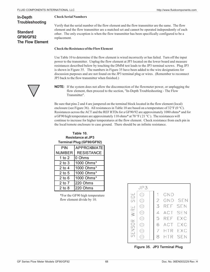
FLUID COMPONENTS INTERNATIONAL LLC http://www.fluidcomponents.com
GF Series Flow Meter Models GF90/GF92 68 Doc. No. 06EN003229 Rev. H
PIN NUMBER
APPROXIMATE RESISTANCE
1 to 2 0 Ohms2 to 3 1000 Ohms*2 to 4 1000 Ohms*2 to 5 1000 Ohms*2 to 6 1000 Ohms*2 to 7 220 Ohms2 to 8 220 Ohms
Check Serial Numbers
Verify that the serial number of the flow element and the flow transmitter are the same. The flowelement and the flow transmitter are a matched set and cannot be operated independently of eachother. The only exception is when the flow transmitter has been specifically configured to be areplacement.
Check the Resistance of the Flow Element
Use Table 10 to determine if the flow element is wired incorrectly or has failed. Turn off the inputpower to the transmitter. Unplug the flow element at JP3 located on the lower board and measureresistances described below by touching the DMM test leads to the JP3 terminal screws. Plug JP3is shown in Figure 35. The numbers in Figure 35 have been added to the wire designations fordiscussion purposes and are not found on the JP3 terminal plug or wires. (Remember to reconnectJP3 back to the flow transmitter when finished.)
NOTE: If the system does not allow the disconnection of the flowmeter power, or unplugging theflow element, then proceed to the section, "In-Depth Troubleshooting - The FlowTransmitter".
Be sure that pins 2 and 4 are jumpered on the terminal block located in the flow element (local)enclosure (see Figure 36). All resistances in Table 10 are based on a temperature of 32°F (0 °C).Resistances across the ACT and the REF RTDs for a GF90/92 are approximately 1080 ohms* and fora GF90 high temperature are approximately 110 ohms* at 70 °F ( 21 °C ). The resistances willcontinue to increase for higher temperatures at the flow element. Check resistance from each pin inthe local/remote enclosure to case ground. There should be an infinite resistance.
In-DepthTroubleshooting
StandardGF90/GF92The Flow Element
Table 10.Resistance at JP3
Terminal Plug (GF90/GF92)
Figure 35. JP3 Terminal Plug
*For the GF90 high temperatureflow element divide by 10.
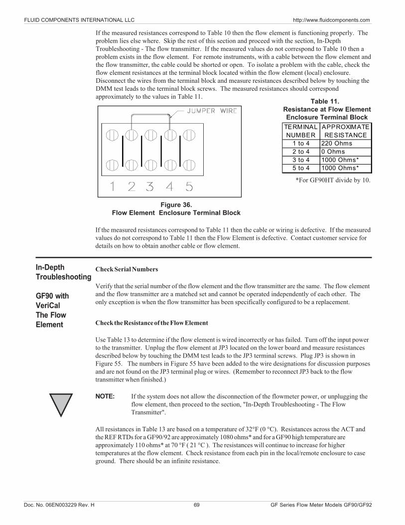
Doc. No. 06EN003229 Rev. H 69 GF Series Flow Meter Models GF90/GF92
FLUID COMPONENTS INTERNATIONAL LLC http://www.fluidcomponents.com
TERMINAL NUMBER
APPROXIMATE RESISTANCE
1 to 4 220 Ohms2 to 4 0 Ohms3 to 4 1000 Ohms*5 to 4 1000 Ohms*
If the measured resistances correspond to Table 10 then the flow element is functioning properly. Theproblem lies else where. Skip the rest of this section and proceed with the section, In-DepthTroubleshooting - The flow transmitter. If the measured values do not correspond to Table 10 then aproblem exists in the flow element. For remote instruments, with a cable between the flow element andthe flow transmitter, the cable could be shorted or open. To isolate a problem with the cable, check theflow element resistances at the terminal block located within the flow element (local) enclosure.Disconnect the wires from the terminal block and measure resistances described below by touching theDMM test leads to the terminal block screws. The measured resistances should correspondapproximately to the values in Table 11.
If the measured resistances correspond to Table 11 then the cable or wiring is defective. If the measuredvalues do not correspond to Table 11 then the Flow Element is defective. Contact customer service fordetails on how to obtain another cable or flow element.
*For GF90HT divide by 10.
Table 11. Resistance at Flow Element Enclosure Terminal Block
Figure 36.Flow Element Enclosure Terminal Block
In-DepthTroubleshooting
GF90 withVeriCalThe FlowElement
Check Serial Numbers
Verify that the serial number of the flow element and the flow transmitter are the same. The flow elementand the flow transmitter are a matched set and cannot be operated independently of each other. Theonly exception is when the flow transmitter has been specifically configured to be a replacement.
Check the Resistance of the Flow Element
Use Table 13 to determine if the flow element is wired incorrectly or has failed. Turn off the input powerto the transmitter. Unplug the flow element at JP3 located on the lower board and measure resistancesdescribed below by touching the DMM test leads to the JP3 terminal screws. Plug JP3 is shown inFigure 55. The numbers in Figure 55 have been added to the wire designations for discussion purposesand are not found on the JP3 terminal plug or wires. (Remember to reconnect JP3 back to the flowtransmitter when finished.)
NOTE: If the system does not allow the disconnection of the flowmeter power, or unplugging theflow element, then proceed to the section, "In-Depth Troubleshooting - The FlowTransmitter".
All resistances in Table 13 are based on a temperature of 32°F (0 °C). Resistances across the ACT andthe REF RTDs for a GF90/92 are approximately 1080 ohms* and for a GF90 high temperature areapproximately 110 ohms* at 70 °F ( 21 °C ). The resistances will continue to increase for highertemperatures at the flow element. Check resistance from each pin in the local/remote enclosure to caseground. There should be an infinite resistance.
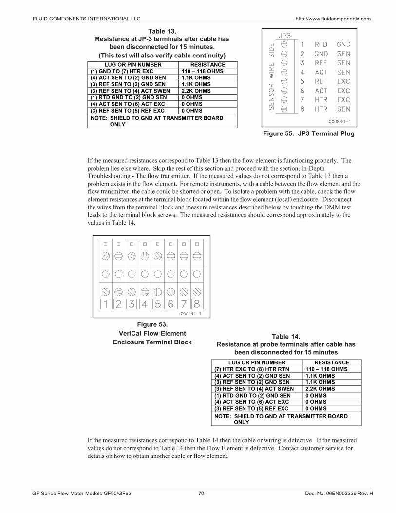
FLUID COMPONENTS INTERNATIONAL LLC http://www.fluidcomponents.com
GF Series Flow Meter Models GF90/GF92 70 Doc. No. 06EN003229 Rev. H
Table 13.Resistance at JP-3 terminals after cable has
been disconnected for 15 minutes.(This test will also verify cable continuity)
Figure 55. JP3 Terminal Plug
If the measured resistances correspond to Table 13 then the flow element is functioning properly. Theproblem lies else where. Skip the rest of this section and proceed with the section, In-DepthTroubleshooting - The flow transmitter. If the measured values do not correspond to Table 13 then aproblem exists in the flow element. For remote instruments, with a cable between the flow element and theflow transmitter, the cable could be shorted or open. To isolate a problem with the cable, check the flowelement resistances at the terminal block located within the flow element (local) enclosure. Disconnectthe wires from the terminal block and measure resistances described below by touching the DMM testleads to the terminal block screws. The measured resistances should correspond approximately to thevalues in Table 14.
If the measured resistances correspond to Table 14 then the cable or wiring is defective. If the measuredvalues do not correspond to Table 14 then the Flow Element is defective. Contact customer service fordetails on how to obtain another cable or flow element.
Figure 53.VeriCal Flow Element
Enclosure Terminal BlockTable 14.
Resistance at probe terminals after cable hasbeen disconnected for 15 minutes
LUG OR PIN NUMBER RESISTANCE (7) HTR EXC TO (8) HTR RTN 110 – 118 OHMS (4) ACT SEN TO (2) GND SEN 1.1K OHMS (3) REF SEN TO (2) GND SEN 1.1K OHMS (3) REF SEN TO (4) ACT SWEN 2.2K OHMS (1) RTD GND TO (2) GND SEN 0 OHMS (4) ACT SEN TO (6) ACT EXC 0 OHMS (3) REF SEN TO (5) REF EXC 0 OHMS NOTE: SHIELD TO GND AT TRANSMITTER BOARD
ONLY
LUG OR PIN NUMBER RESISTANCE (1) GND TO (7) HTR EXC 110 – 118 OHMS (4) ACT SEN TO (2) GND SEN 1.1K OHMS (3) REF SEN TO (2) GND SEN 1.1K OHMS (3) REF SEN TO (4) ACT SWEN 2.2K OHMS (1) RTD GND TO (2) GND SEN 0 OHMS (4) ACT SEN TO (6) ACT EXC 0 OHMS (3) REF SEN TO (5) REF EXC 0 OHMS NOTE: SHIELD TO GND AT TRANSMITTER BOARD
ONLY
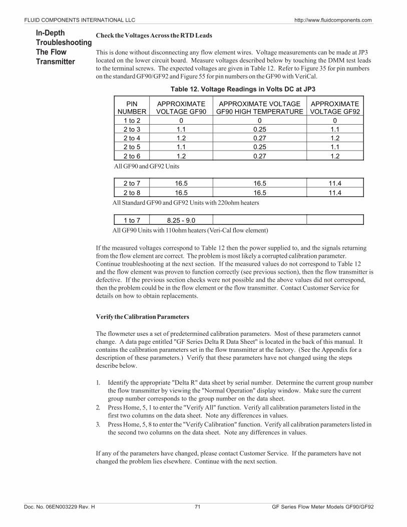
Doc. No. 06EN003229 Rev. H 71 GF Series Flow Meter Models GF90/GF92
FLUID COMPONENTS INTERNATIONAL LLC http://www.fluidcomponents.com
Check the Voltages Across the RTD Leads
This is done without disconnecting any flow element wires. Voltage measurements can be made at JP3located on the lower circuit board. Measure voltages described below by touching the DMM test leadsto the terminal screws. The expected voltages are given in Table 12. Refer to Figure 35 for pin numberson the standard GF90/GF92 and Figure 55 for pin numbers on the GF90 with VeriCal.
If the measured voltages correspond to Table 12 then the power supplied to, and the signals returningfrom the flow element are correct. The problem is most likely a corrupted calibration parameter.Continue troubleshooting at the next section. If the measured values do not correspond to Table 12and the flow element was proven to function correctly (see previous section), then the flow transmitter isdefective. If the previous section checks were not possible and the above values did not correspond,then the problem could be in the flow element or the flow transmitter. Contact Customer Service fordetails on how to obtain replacements.
Verify the Calibration Parameters
The flowmeter uses a set of predetermined calibration parameters. Most of these parameters cannotchange. A data page entitled "GF Series Delta R Data Sheet" is located in the back of this manual. Itcontains the calibration parameters set in the flow transmitter at the factory. (See the Appendix for adescription of these parameters.) Verify that these parameters have not changed using the stepsdescribe below.
1. Identify the appropriate "Delta R" data sheet by serial number. Determine the current group numberthe flow transmitter by viewing the "Normal Operation" display window. Make sure the currentgroup number corresponds to the group number on the data sheet.
2. Press Home, 5, 1 to enter the "Verify All" function. Verify all calibration parameters listed in thefirst two columns on the data sheet. Note any differences in values.
3. Press Home, 5, 8 to enter the "Verify Calibration" function. Verify all calibration parameters listed inthe second two columns on the data sheet. Note any differences in values.
If any of the parameters have changed, please contact Customer Service. If the parameters have notchanged the problem lies elsewhere. Continue with the next section.
In-DepthTroubleshootingThe FlowTransmitter
PIN NUMBER
APPROXIMATE VOLTAGE GF90
APPROXIMATE VOLTAGE GF90 HIGH TEMPERATURE
APPROXIMATE VOLTAGE GF92
1 to 2 0 0 0 2 to 3 1.1 0.25 1.1 2 to 4 1.2 0.27 1.2 2 to 5 1.1 0.25 1.1 2 to 6 1.2 0.27 1.2
2 to 7 16.5 16.5 11.4 2 to 8 16.5 16.5 11.4
1 to 7 8.25 - 9.0
Table 12. Voltage Readings in Volts DC at JP3
All GF90 and GF92 Units
All Standard GF90 and GF92 Units with 220ohm heaters
All GF90 Units with 110ohm heaters (Veri-Cal flow element)
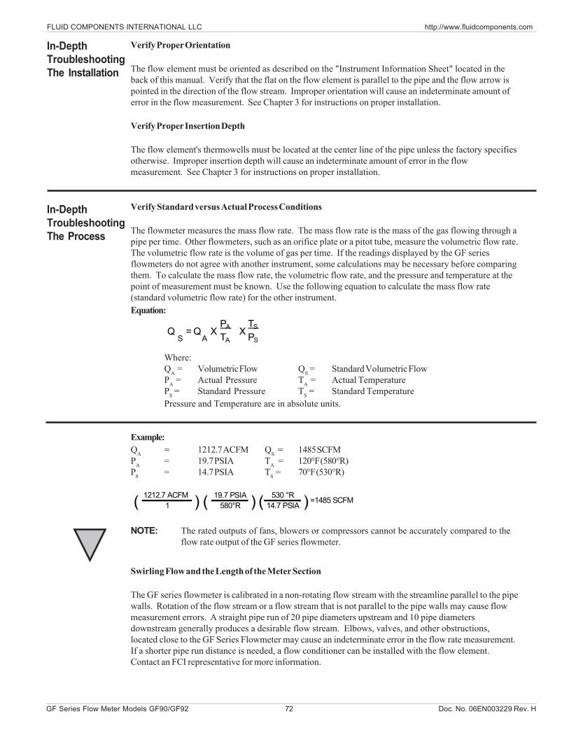
FLUID COMPONENTS INTERNATIONAL LLC http://www.fluidcomponents.com
GF Series Flow Meter Models GF90/GF92 72 Doc. No. 06EN003229 Rev. H
1212.7 ACFM 19.7 PSIA 530 °R1 580°R 14.7 PSIA( ) =1485 SCFM( ) ( )
QS
= QA
XPA
TAX
TS
PS
Verify Proper Orientation
The flow element must be oriented as described on the "Instrument Information Sheet" located in theback of this manual. Verify that the flat on the flow element is parallel to the pipe and the flow arrow ispointed in the direction of the flow stream. Improper orientation will cause an indeterminate amount oferror in the flow measurement. See Chapter 3 for instructions on proper installation.
Verify Proper Insertion Depth
The flow element's thermowells must be located at the center line of the pipe unless the factory specifiesotherwise. Improper insertion depth will cause an indeterminate amount of error in the flowmeasurement. See Chapter 3 for instructions on proper installation.
Verify Standard versus Actual Process Conditions
The flowmeter measures the mass flow rate. The mass flow rate is the mass of the gas flowing through apipe per time. Other flowmeters, such as an orifice plate or a pitot tube, measure the volumetric flow rate.The volumetric flow rate is the volume of gas per time. If the readings displayed by the GF seriesflowmeters do not agree with another instrument, some calculations may be necessary before comparingthem. To calculate the mass flow rate, the volumetric flow rate, and the pressure and temperature at thepoint of measurement must be known. Use the following equation to calculate the mass flow rate(standard volumetric flow rate) for the other instrument.Equation:
Where:QA = Volumetric Flow QS = Standard Volumetric FlowPA = Actual Pressure TA = Actual TemperaturePS = Standard Pressure TS = Standard TemperaturePressure and Temperature are in absolute units.
In-DepthTroubleshootingThe Installation
In-DepthTroubleshootingThe Process
Example:QA = 1212.7 ACFM QS = 1485 SCFMPA = 19.7 PSIA TA = 120°F (580°R)PS = 14.7 PSIA TS = 70°F (530°R)
NOTE: The rated outputs of fans, blowers or compressors cannot be accurately compared to theflow rate output of the GF series flowmeter.
Swirling Flow and the Length of the Meter Section
The GF series flowmeter is calibrated in a non-rotating flow stream with the streamline parallel to the pipewalls. Rotation of the flow stream or a flow stream that is not parallel to the pipe walls may cause flowmeasurement errors. A straight pipe run of 20 pipe diameters upstream and 10 pipe diametersdownstream generally produces a desirable flow stream. Elbows, valves, and other obstructions,located close to the GF Series Flowmeter may cause an indeterminate error in the flow rate measurement.If a shorter pipe run distance is needed, a flow conditioner can be installed with the flow element.Contact an FCI representative for more information.
Doc. No. 06EN003229 Rev. H 73 GF Series Flow Meter Models GF90/GF92
FLUID COMPONENTS INTERNATIONAL LLC http://www.fluidcomponents.com
Condensation, Pulsing Flow or Transient Flow
If a component of the process media is near its saturation temperature it is probably condensing on theflow element. Liquid on the flow element will drive the flow measurement higher than actual. The flowelement must be placed somewhere else in the process where the flow stream temperature is well abovethe saturation temperature and below the saturation pressure of any of the process gases.Pulsing or transient flows will cause the flowmeter measurement to be higher than actual. Compressors,fans, blowers, etc. commonly induce pulsation within the flow stream. The flow element should belocated at least 20 diameters downstream and 10 diameters upstream of any compressor, fan or blower.Transient flow (quick increases or decrease flow rate) may cause an indeterminate amount of error in theflow measurement. The flow rate measurements made during quick changes in flow rate should bediscarded.
Natural Convection in Vertical Pipes and Ducts
A long, vertical stand of pipe that has no induced flow may have a circulation of gas caused by freeconvection. If the flowmeter was calibrated to measure small flow rates the convection current maycause a flow reading. If this is undesirable, move the flow element to another location.
The Relays
See Chapter 4 for instructions on setting the relays. From the keypad, the relay state can be switched.This can be used to test the interface with the GF series relays.
To test the relays:1. From the Main menu press 2. The "2.0 PORT SETUP" menu title will appear.2. Press 2, the "Relay Setup" option.3. Press 3, for the "Test Relays" option.4. Pressing 1 or 2 will toggle the states of the respective relays. The present state of the
relays are displayed in parenthesis.
The relays toggle between energized and de-energized and the state should be reported in the statusline of the "Normal Operation" window. Changing states also cause an audible click.
OtherTroubleshooting
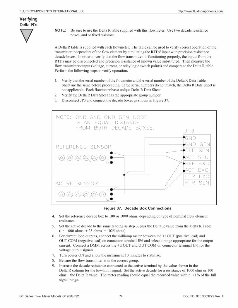
FLUID COMPONENTS INTERNATIONAL LLC http://www.fluidcomponents.com
GF Series Flow Meter Models GF90/GF92 74 Doc. No. 06EN003229 Rev. H
NOTE: Be sure to use the Delta R table supplied with this flowmeter. Use two decade resistanceboxes, and or fixed resistors.
A Delta R table is supplied with each flowmeter. The table can be used to verify correct operation of thetransmitter independent of the flow element by simulating the RTDs' input with precision resistancedecade boxes. In order to verify that the flow transmitter is functioning properly, the inputs from theRTDs may be disconnected and precision resistance of known value substituted. Then measure theflow transmitter output (voltage, current, or relay logic switch points) and compare to the Delta R table.Perform the following steps to verify operation.
1. Verify that the serial number of the flowmeter and the serial number of the Delta R Data TableSheet are the same before proceeding. If the serial numbers do not match, the Delta R Data Sheet isnot applicable. Each flowmeter has a unique Delta R Data Sheet.
2. Verify the Delta R Data Sheet has the appropriate group number.3. Disconnect JP3 and connect the decade boxes as shown in Figure 37.
4. Set the reference decade box to 100 or 1000 ohms, depending on type of nominal flow elementresistance.
5. Set the active decade to the same reading as step 3, plus the Delta R value from the Delta R Table(i.e. 1000 ohms + 25 ohms = 1025 ohms).
6. For current loop outputs, connect the milliamp meter between the +I OUT (positive lead) andOUT COM (negative lead) on connector terminal JP6 and select a range appropriate for the outputcurrent. Connect a DMM across the +E OUT and OUT COM on connector terminal JP6 for thevoltage output signals.
7. Turn power ON and allow the instrument 10 minutes to stabilize.8. Be sure the flow transmitter is in the correct group.9. Increase the decade resistance connected to the active terminal by the value shown in the
Delta R column for the low-limit signal. Set the active decade for a resistance of 1000 ohm or 100ohm + the Delta R value. The meter reading should equal the recorded value within ±1% of the fullsignal range.
Figure 37. Decade Box Connections
VerifyingDelta R’s
Doc. No. 06EN003229 Rev. H 75 GF Series Flow Meter Models GF90/GF92
FLUID COMPONENTS INTERNATIONAL LLC http://www.fluidcomponents.com
Example: 4-20 milliampere Output Signal = 1% of 16 milliampere = 0.16 milliampere = Tolerance.
10. Repeat Step 7 for the other flow rates in the Delta R Table for this flowmeter.11. Compare results of the verification measurements with the output signal values recorded on the
Delta R Data Sheet to determine if the transmitter is functioning properly. Also verify the displayreading matches.
12. Turn power OFF and disconnect the decade resistors. Connect the proper wires from the flowelement to terminal block.
13. Disconnect the milliamp meter. Connect the output load to the appropriate OUT+ and OUT COMterminals on the lower (I/O/P) board.
14. Close the enclosure, making sure that none of the wires are caught. Ensure that all seals andgaskets are properly installed. If a custom enclosure exists, be sure it is placed back into safeoperating condition.
If the readings are good, the flow transmitter is good and problem may involve the flow element. If readingsare off, a flow element calibration may be required or the flow transmitter needs to be setup.
NOTE: Any unauthorized repair attempts will void the warranty.
At this time FCI does not consider there to be any field-repairable items with the exception of the replacementof fuses F1 and F2. Any repair at the component level for either the flow elements and enclosure or the flowtransmitter and attached components is not advised or recommended by FCI.Contact the authorized FCI field representative (see list of regional territories and the respective agents) orFCI (see telephone and FAX numbers later in this manual) to determine the best course of action.
Before returning any equipment to FCI, please obtain an RA number for authorization, tracking, and repair/replacement instructions. If a return is required, remove defective instrument, replace with spare, calibrate,then return defective instrument to FCI freight prepaid for disposition.
1. In the event of problems or inquiries regarding the flowmeter, please contact the regionalor country authorized FCI Field Agent. There is an extensive list of these representativesat the front of this manual.
2. Before contacting the FCI representative, please be sure that all the applicableinformation is near so that a more effective, efficient and timely response may beprovided.
3. Refer to Appendix D for specific Customer Service policy provisions.
DefectiveParts
CustomerService
Repair

FLUID COMPONENTS INTERNATIONAL LLC http://www.fluidcomponents.com
GF Series Flow Meter Models GF90/GF92 76 Doc. No. 06EN003229 Rev. H
THIS PAGE INTENTIONALLY LEFT BLANK
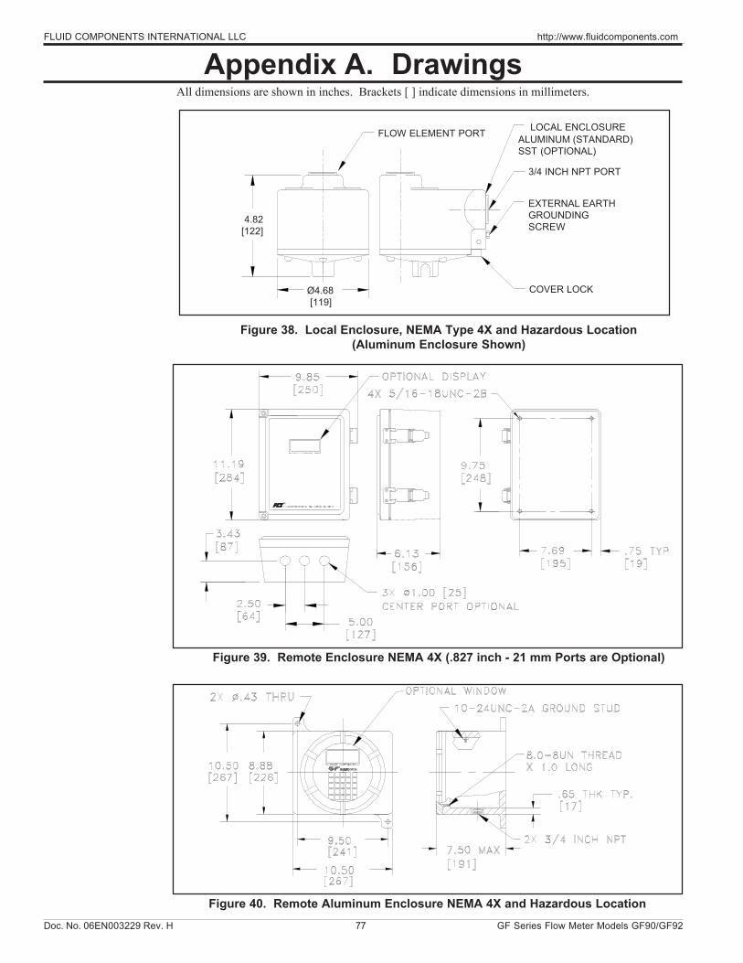
Doc. No. 06EN003229 Rev. H 77 GF Series Flow Meter Models GF90/GF92
FLUID COMPONENTS INTERNATIONAL LLC http://www.fluidcomponents.com
Appendix A. DrawingsAll dimensions are shown in inches. Brackets [ ] indicate dimensions in millimeters.
Figure 38. Local Enclosure, NEMA Type 4X and Hazardous Location(Aluminum Enclosure Shown)
Figure 39. Remote Enclosure NEMA 4X (.827 inch - 21 mm Ports are Optional)
Ø4.68 [119]
LOCAL ENCLOSUREALUMINUM (STANDARD)SST (OPTIONAL)
FLOW ELEMENT PORT
EXTERNAL EARTHGROUNDINGSCREW
3/4 INCH NPT PORT
COVER LOCK
4.82[122]
Figure 40. Remote Aluminum Enclosure NEMA 4X and Hazardous Location
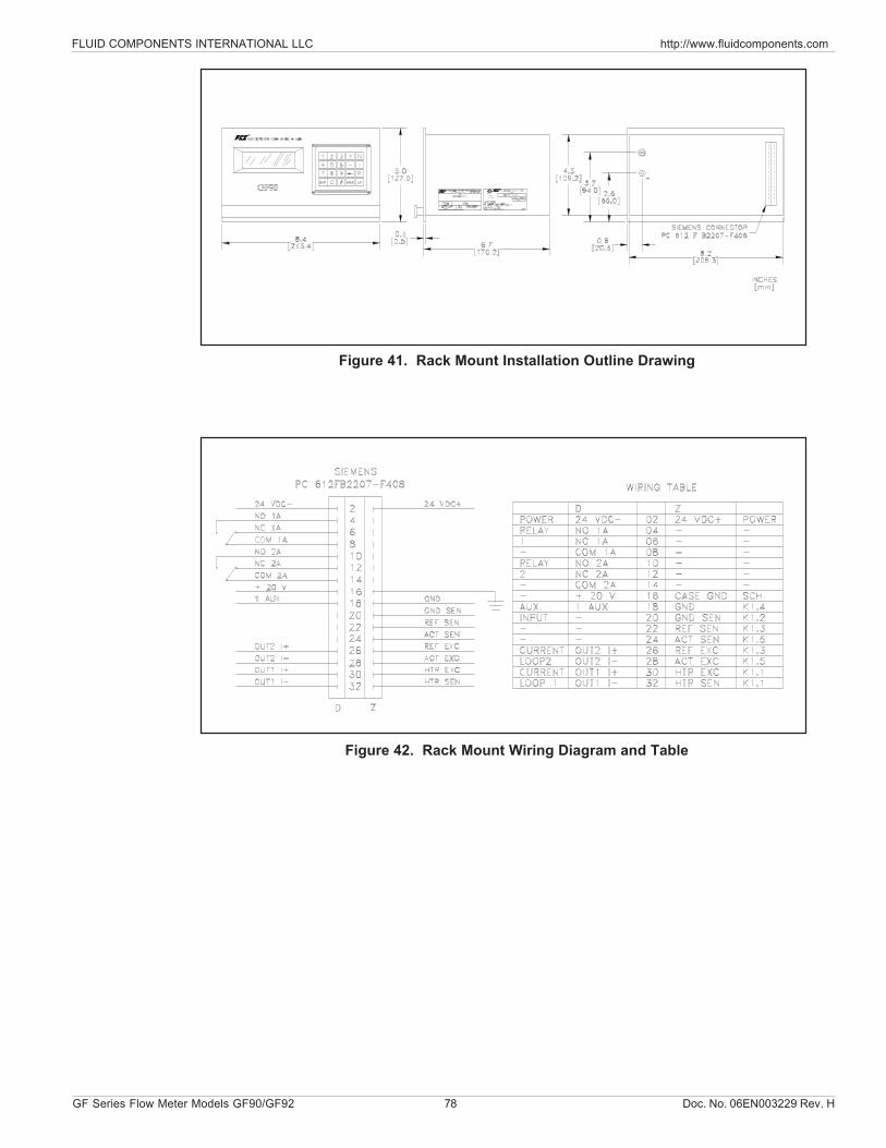
FLUID COMPONENTS INTERNATIONAL LLC http://www.fluidcomponents.com
GF Series Flow Meter Models GF90/GF92 78 Doc. No. 06EN003229 Rev. H
Figure 42. Rack Mount Wiring Diagram and Table
Figure 41. Rack Mount Installation Outline Drawing
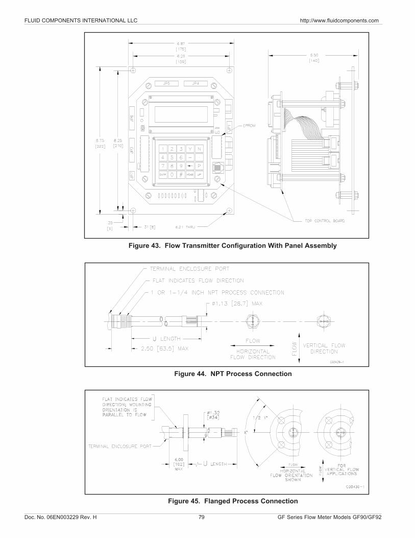
Doc. No. 06EN003229 Rev. H 79 GF Series Flow Meter Models GF90/GF92
FLUID COMPONENTS INTERNATIONAL LLC http://www.fluidcomponents.com
Figure 44. NPT Process Connection
Figure 43. Flow Transmitter Configuration With Panel Assembly
Figure 45. Flanged Process Connection
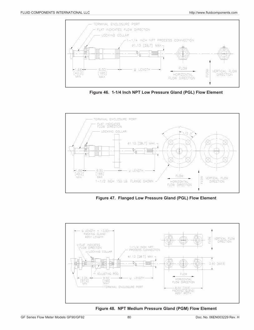
FLUID COMPONENTS INTERNATIONAL LLC http://www.fluidcomponents.com
GF Series Flow Meter Models GF90/GF92 80 Doc. No. 06EN003229 Rev. H
Figure 46. 1-1/4 Inch NPT Low Pressure Gland (PGL) Flow Element
Figure 47. Flanged Low Pressure Gland (PGL) Flow Element
Figure 48. NPT Medium Pressure Gland (PGM) Flow Element
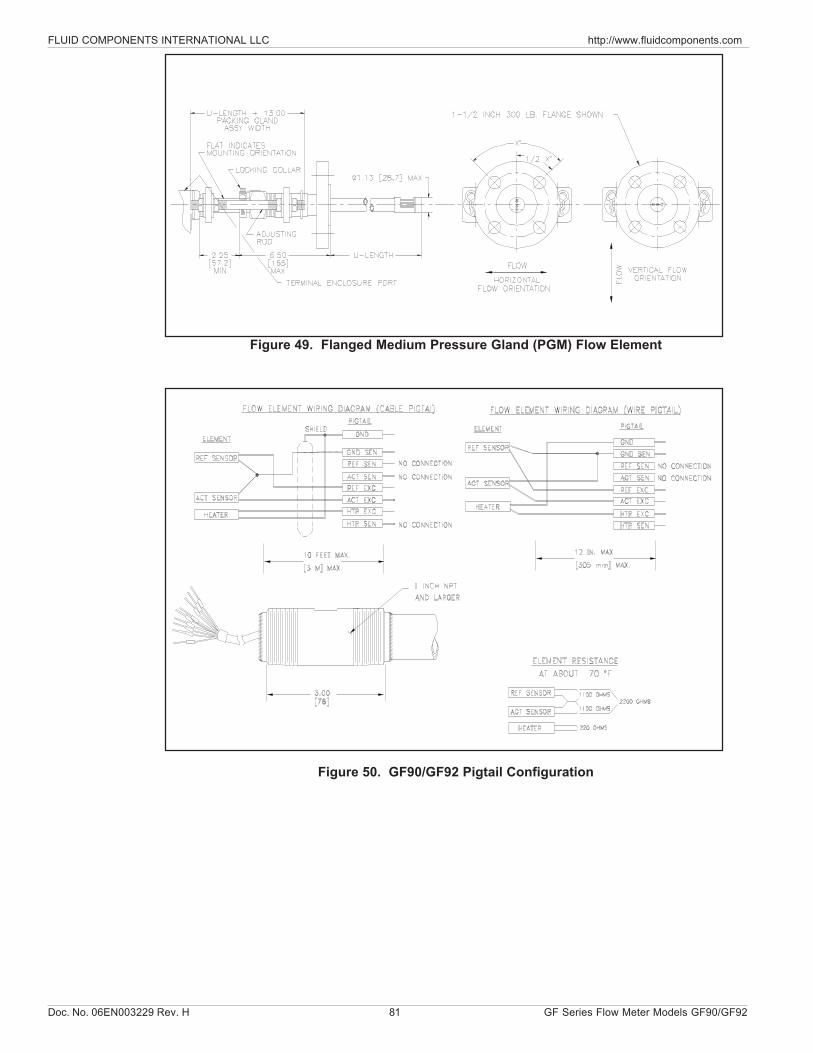
Doc. No. 06EN003229 Rev. H 81 GF Series Flow Meter Models GF90/GF92
FLUID COMPONENTS INTERNATIONAL LLC http://www.fluidcomponents.com
Figure 49. Flanged Medium Pressure Gland (PGM) Flow Element
Figure 50. GF90/GF92 Pigtail Configuration
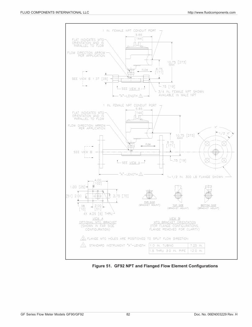
FLUID COMPONENTS INTERNATIONAL LLC http://www.fluidcomponents.com
GF Series Flow Meter Models GF90/GF92 82 Doc. No. 06EN003229 Rev. H
Figure 51. GF92 NPT and Flanged Flow Element Configurations
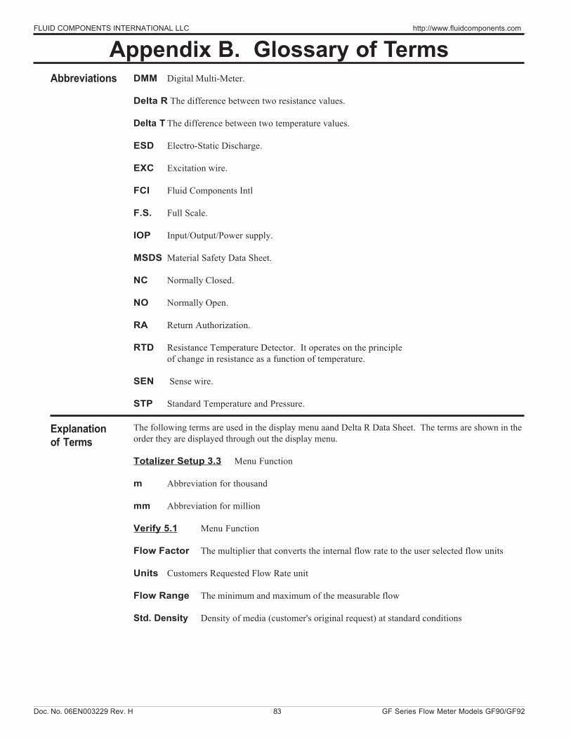
Doc. No. 06EN003229 Rev. H 83 GF Series Flow Meter Models GF90/GF92
FLUID COMPONENTS INTERNATIONAL LLC http://www.fluidcomponents.com
Appendix B. Glossary of Terms
Explanationof Terms
Abbreviations DMM Digital Multi-Meter.
Delta R The difference between two resistance values.
Delta T The difference between two temperature values.
ESD Electro-Static Discharge.
EXC Excitation wire.
FCI Fluid Components Intl
F.S. Full Scale.
IOP Input/Output/Power supply.
MSDS Material Safety Data Sheet.
NC Normally Closed.
NO Normally Open.
RA Return Authorization.
RTD Resistance Temperature Detector. It operates on the principleof change in resistance as a function of temperature.
SEN Sense wire.
STP Standard Temperature and Pressure.
The following terms are used in the display menu aand Delta R Data Sheet. The terms are shown in theorder they are displayed through out the display menu.
Totalizer Setup 3.3 Menu Function
m Abbreviation for thousand
mm Abbreviation for million
Verify 5.1 Menu Function
Flow Factor The multiplier that converts the internal flow rate to the user selected flow units
Units Customers Requested Flow Rate unit
Flow Range The minimum and maximum of the measurable flow
Std. Density Density of media (customer's original request) at standard conditions
FLUID COMPONENTS INTERNATIONAL LLC http://www.fluidcomponents.com
GF Series Flow Meter Models GF90/GF92 84 Doc. No. 06EN003229 Rev. H
Area Cross-sectional area of pipe or duct
Diameter Inner diameter of pipe
Temp. Unit Unit of temperature
Tcal Add A value that is added to measured temperature (default is 0)
Tcal Mult A value that is multiplied by the measured temperature (default is 1)
Relay 1 Current status of Relay 1, energized or de-energized
Above, Below, See Chapter 4 Relays, for the explanationInside or Outside
H: Hysteresis value (in flow rate units such as 50 SCFM etc.)
D: Delay in seconds
Relay 2 Current status of Relay 2, energized or de-energized
Port 1 Channel 1 output signal
Mode Current (4 - 20 mA) or Volts (0 - 5, 0 - 10, etc.) output
F.S. Full Scale: 100% of flow rate
Zero 0.00 for zero based and Min flow for non-zero based
Port 2 Channel 2 output signal
Corr1 through Corr4 Correction Factors: Default is Corr 2 = 1 and Corr1, 3, 4 = 0(Flow) = Corr1 + Corr2(Flow) + Corr3(Flow)2 + Corr4(Flow)3
Menu 5.8 Menu Function
dR gain Digital representation of A/D# for DR value - derivedduring front-end set-up: R = dR Gain X A/D# + dR Off
R gain Digital representation of A/D# for REF RTD value - derivedduring front-end setup: REF R = R Gain X A/D# + R Off
dR Off Offset value of equation: R = dR Gain X A/D# + dR Off
Ref off Offset/constant value for REF RTD derivedduring front-end set-up: REF R = R Gain X A/D/# + R Off
Offset 1 Offset for equation: REF R = R Gain X A/D# + R Off
Slope 1 Slope for equation: D/A# = current X Slope 1 + Off 1.Corresponding to current or voltage output
Offset 2 Offset for equation: REF R = R Gain X A/D# + R Off
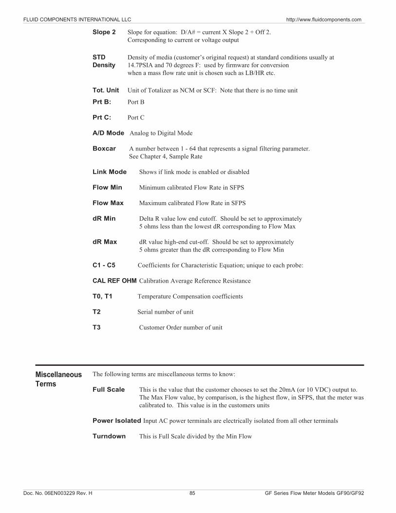
Doc. No. 06EN003229 Rev. H 85 GF Series Flow Meter Models GF90/GF92
FLUID COMPONENTS INTERNATIONAL LLC http://www.fluidcomponents.com
Prt B: Port B
Prt C: Port C
A/D Mode Analog to Digital Mode
Boxcar A number between 1 - 64 that represents a signal filtering parameter. See Chapter 4, Sample Rate
Link Mode Shows if link mode is enabled or disabled
Flow Min Minimum calibrated Flow Rate in SFPS
Flow Max Maximum calibrated Flow Rate in SFPS
dR Min Delta R value low end cutoff. Should be set to approximately5 ohms less than the lowest dR corresponding to Flow Max
dR Max dR value high-end cut-off. Should be set to approximately 5 ohms greater than the dR corresponding to Flow Min
C1 - C5 Coefficients for Characteristic Equation; unique to each probe:
CAL REF OHM Calibration Average Reference Resistance
T0, T1 Temperature Compensation coefficients
T2 Serial number of unit
T3 Customer Order number of unit
The following terms are miscellaneous terms to know:
Full Scale This is the value that the customer chooses to set the 20mA (or 10 VDC) output to.The Max Flow value, by comparison, is the highest flow, in SFPS, that the meter wascalibrated to. This value is in the customers units
Power Isolated Input AC power terminals are electrically isolated from all other terminals
Turndown This is Full Scale divided by the Min Flow
MiscellaneousTerms
Slope 2 Slope for equation: D/A# = current X Slope 2 + Off 2.Corresponding to current or voltage output
STD Density of media (customer’s original request) at standard conditions usually atDensity 14.7PSIA and 70 degrees F: used by firmware for conversion
when a mass flow rate unit is chosen such as LB/HR etc.
Tot. Unit Unit of Totalizer as NCM or SCF: Note that there is no time unit

FLUID COMPONENTS INTERNATIONAL LLC http://www.fluidcomponents.com
GF Series Flow Meter Models GF90/GF92 86 Doc. No. 06EN003229 Rev. H
THIS PAGE INTENTIONALLY LEFT BLANK
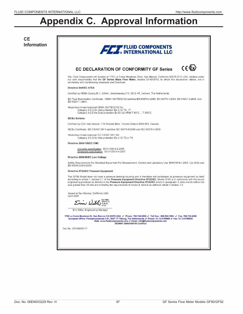
Doc. No. 06EN003229 Rev. H 87 GF Series Flow Meter Models GF90/GF92
FLUID COMPONENTS INTERNATIONAL LLC http://www.fluidcomponents.com
Appendix C. Approval InformationCEInformation
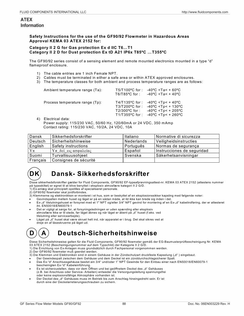
FLUID COMPONENTS INTERNATIONAL LLC http://www.fluidcomponents.com
GF Series Flow Meter Models GF90/GF92 88 Doc. No. 06EN003229 Rev. H
ATEXInformation
Safety Instructions for the use of the GF90/92 Flowmeter in Hazardous Areas Approval KEMA 03 ATEX 2152 for: Category II 2 G for Gas protection Ex d IIC T6…T1 Category II 2 D for Dust protection Ex tD A21 IP6x T85ºC …T355ºC The GF90/92 series consist of a sensing element and remote mounted electronics mounted in a type “d” flameproof enclosure.
1) The cable entries are 1 inch Female NPT. 2) Cables must be terminated in either a safe area or within ATEX approved enclosures. 3) The temperature classes for both ambient and process temperature ranges are as follows:
Ambient temperature range (Ta): T5/T100ºC for : -40ºC <Ta< + 60ºC T6/T85ºC for : -40ºC <Ta< + 40ºC
Process temperature range (Tp): T4/T135ºC for : -40ºC <Tp< + 40ºC
T3/T200ºC for : -40ºC <Tp< + 130ºC T2/300ºC for : -40ºC <Tp< + 205ºC T1/T355ºC for : -40ºC <Tp< + 260ºC
4) Electrical data: Power supply: 115/230 VAC, 50/60 Hz, 120/60mA or 24 VDC, 350 mAmp Contact rating: 115/230 VAC, 10/2A, 24 VDC, 10A
Dansk Sikkerhedsforskrifter Italiano Normative di sicurezza Deutsch Sicherheitshinweise Nederlands Veiligheidsinstructies English Safety instructions Português Normas de segurança Υπ Υπ_δεί_εις ασφαλείας Español Instrucciones de seguridad Suomi Turvallisuusohjeet Svenska Säkerhetsanvisningar Français Consignes de sécurité
DK Dansk- Sikkerhedsforskrifter Disse sikkerhedsforskrifter gælder for Fluid Components, GF90/92 EF-typeafprøvningsattest-nr. KEMA 03 ATEX 2152 (attestens nummer på typeskiltet) er egnet til at blive benyttet i eksplosiv atmosfære kategori II 2 G/D. 1) Ex-anlæg skal principielt opstilles af specialiseret personale. 2) GF90/92 flowmeter skal jordforbindes. 3) Klemmerne og elektronikken er monteret i et hus, som er beskyttet af en eksplosionssikker kapsling med følgende noter: • Gevindspalten mellem huset og låget er på en sådan måde, at ild ikke kan brede sig inden i det. • Ex-„d“ tilslutningshuset er forsynet med et 1" NPT og/eller 3/4" NPT gevind for montering af en Ex-„d“ kabelindføring, der er attesteret
iht. EN50018/EN60079-1 • Det er vigtigt at sørge for, at forsyningsledningen er uden spænding eller eksplosiv
atmosfære ikke er til stede, før låget åbnes og når låget er åbent på „d” huset (f.eks. ved tilslutning eller servicearbejde).
• Låget på „d” huset skal være skruet helt ind, når apparatet er i brug. Det skal sikres ved at dreje en af låseskruerne på låget ud.
D A Deutsch-Sicherheitshinweise Diese Sicherheitshinweise gelten für die Fluid Components, GF90/92 flowmeter gemäß der EG-Baumusterprüfbescheinigung Nr. KEMA 03 ATEX 2152 (Bescheinigungsnummer auf dem Typschild) der Kategorie II 2 G/D. 1) Die Errichtung von Ex-Anlagen muss grundsätzlich durch Fachpersonal vorgenommen werden. 2) Der GF90/92 flowmeter muß geerdet werden. 3) Die Klemmen und Elektroniken sind in einem Gehäuse in der Zündschutzart druckfeste Kapselung („d“ ) eingebaut. • Der Gewindespalt zwischen dem Gehäuse und dem Deckel ist ein zünddurchschlagsicherer Spalt. • Das Ex-“d“ Anschlussgehäuse besitzt ein 3/4“ und/oder 1” NPT Gewinde für den Einbau einer nach EN50018/EN60079-1
bescheinigten Ex-“d“ Kabeleinführung. • Es ist sicherzustellen, dass vor dem Öffnen und bei geöffnetem Deckel des „d“ Gehäuses
(z.B. bei Anschluss oder Service- Arbeiten) entweder die Versorgungsleitung spannungsfrei oder keine explosionsfähige Atmosphäre vorhanden ist.
• Der Deckel des „d“ Gehäuses muss im Betrieb bis zum Anschlag hineingedreht sein. Er ist durch eine der Deckelarretierungsschrauben zu sichern.
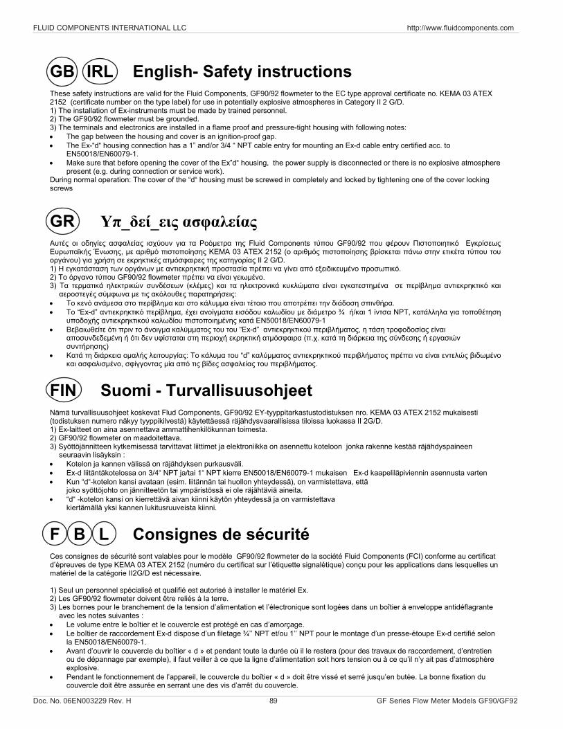
Doc. No. 06EN003229 Rev. H 89 GF Series Flow Meter Models GF90/GF92
FLUID COMPONENTS INTERNATIONAL LLC http://www.fluidcomponents.com
GB IRL English- Safety instructions These safety instructions are valid for the Fluid Components, GF90/92 flowmeter to the EC type approval certificate no. KEMA 03 ATEX 2152 (certificate number on the type label) for use in potentially explosive atmospheres in Category II 2 G/D. 1) The installation of Ex-instruments must be made by trained personnel. 2) The GF90/92 flowmeter must be grounded. 3) The terminals and electronics are installed in a flame proof and pressure-tight housing with following notes: • The gap between the housing and cover is an ignition-proof gap. • The Ex-“d“ housing connection has a 1” and/or 3/4 “ NPT cable entry for mounting an Ex-d cable entry certified acc. to
EN50018/EN60079-1. • Make sure that before opening the cover of the Ex”d“ housing, the power supply is disconnected or there is no explosive atmosphere
present (e.g. during connection or service work). During normal operation: The cover of the “d“ housing must be screwed in completely and locked by tightening one of the cover locking screws
GR Υπ_δεί_εις ασφαλείας Αυτές οι οδηγίες ασφαλείας ισχύουν για τα Ροόµετρα της Fluid Components τύπου GF90/92 που φέρουν Πιστοποιητικό Εγκρίσεως Ευρωπαϊκής Ένωσης, µε αριθµό πιστοποίησης KEMA 03 ATEX 2152 (ο αριθµός πιστοποίησης βρίσκεται πάνω στην ετικέτα τύπου του οργάνου) για χρήση σε εκρηκτικές ατµόσφαιρες της κατηγορίας II 2 G/D. 1) Η εγκατάσταση των οργάνων µε αντιεκρηκτική προστασία πρέπει να γίνει από εξειδικευµένο προσωπικό. 2) Το όργανο τύπου GF90/92 flowmeter πρέπει να είναι γειωµένο. 3) Τα τερµατικά ηλεκτρικών συνδέσεων (κλέµες) και τα ηλεκτρονικά κυκλώµατα είναι εγκατεστηµένα σε περίβληµα αντιεκρηκτικό και
αεροστεγές σύµφωνα µε τις ακόλουθες παρατηρήσεις: • Το κενό ανάµεσα στο περίβληµα και στο κάλυµµα είναι τέτοιο που αποτρέπει την διάδοση σπινθήρα. • Το “Ex-d” αντιεκρηκτικό περίβληµα, έχει ανοίγµατα εισόδου καλωδίου µε διάµετρο ¾ ή/και 1 ίντσα NPT, κατάλληλα για τοποθέτηση
υποδοχής αντιεκρηκτικού καλωδίου πιστοποιηµένης κατά EN50018/EN60079-1 • Βεβαιωθείτε ότι πριν το άνοιγµα καλύµµατος του του “Ex-d” αντιεκρηκτικού περιβλήµατος, η τάση τροφοδοσίας είναι
αποσυνδεδεµένη ή ότι δεν υφίσταται στη περιοχή εκρηκτική ατµόσφαιρα (π.χ. κατά τη διάρκεια της σύνδεσης ή εργασιών συντήρησης)
• Κατά τη διάρκεια οµαλής λειτουργίας: Το κάλυµα του “d” καλύµµατος αντιεκρηκτικού περιβλήµατος πρέπει να είναι εντελώς βιδωµένο και ασφαλισµένο, σφίγγοντας µία από τις βίδες ασφαλείας του περιβλήµατος.
FIN Suomi - Turvallisuusohjeet Nämä turvallisuusohjeet koskevat Flud Components, GF90/92 EY-tyyppitarkastustodistuksen nro. KEMA 03 ATEX 2152 mukaisesti (todistuksen numero näkyy tyyppikilvestä) käytettäessä räjähdysvaarallisissa tiloissa luokassa II 2G/D. 1) Ex-laitteet on aina asennettava ammattihenkilökunnan toimesta. 2) GF90/92 flowmeter on maadoitettava. 3) Syöttöjännitteen kytkemisessä tarvittavat liittimet ja elektroniikka on asennettu koteloon jonka rakenne kestää räjähdyspaineen
seuraavin lisäyksin : • Kotelon ja kannen välissä on räjähdyksen purkausväli. • Ex-d liitäntäkotelossa on 3/4“ NPT ja/tai 1“ NPT kierre EN50018/EN60079-1 mukaisen Ex-d kaapeliläpiviennin asennusta varten • Kun “d“-kotelon kansi avataan (esim. liitännän tai huollon yhteydessä), on varmistettava, että
joko syöttöjohto on jännitteetön tai ympäristössä ei ole räjähtäviä aineita. • “d“ -kotelon kansi on kierrettävä aivan kiinni käytön yhteydessä ja on varmistettava
kiertämällä yksi kannen lukitusruuveista kiinni. F B L Consignes de sécurité Ces consignes de sécurité sont valables pour le modèle GF90/92 flowmeter de la société Fluid Components (FCI) conforme au certificat d’épreuves de type KEMA 03 ATEX 2152 (numéro du certificat sur l’étiquette signalétique) conçu pour les applications dans lesquelles un matériel de la catégorie II2G/D est nécessaire. 1) Seul un personnel spécialisé et qualifié est autorisé à installer le matériel Ex. 2) Les GF90/92 flowmeter doivent être reliés à la terre. 3) Les bornes pour le branchement de la tension d’alimentation et l’électronique sont logées dans un boîtier à enveloppe antidéflagrante
avec les notes suivantes : • Le volume entre le boîtier et le couvercle est protégé en cas d’amorçage. • Le boîtier de raccordement Ex-d dispose d’un filetage ¾’’ NPT et/ou 1’’ NPT pour le montage d’un presse-étoupe Ex-d certifié selon
la EN50018/EN60079-1. • Avant d’ouvrir le couvercle du boîtier « d » et pendant toute la durée où il le restera (pour des travaux de raccordement, d’entretien
ou de dépannage par exemple), il faut veiller à ce que la ligne d’alimentation soit hors tension ou à ce qu’il n’y ait pas d’atmosphère explosive.
• Pendant le fonctionnement de l’appareil, le couvercle du boîtier « d » doit être vissé et serré jusqu’en butée. La bonne fixation du couvercle doit être assurée en serrant une des vis d’arrêt du couvercle.
FLUID COMPONENTS INTERNATIONAL LLC http://www.fluidcomponents.com
GF Series Flow Meter Models GF90/GF92 90 Doc. No. 06EN003229 Rev. H
I Italiano - Normative di sicurezza Queste normative di sicurezza si riferiscono ai Fluid Components, GF90/92 secondo il certificato CE di prova di omologazione n° KEMA 03 ATEX 2152 (numero del certificato sulla targhetta d’identificazione) sono idonei all’impiego in atmosfere esplosive applicazioni che richiedono apparecchiature elettriche della Categoria II 2 G/D. 1) L’installazione di sistemi Ex deve essere eseguita esclusivamente da personale specializzato. 2) I GF90/92 flowmeter devono essere collegati a terra. 3) I morsetti per il collegamento e l’elettronica sono incorporati in una custodia a prova di esplosione („d“) con le seguenti note: • La sicurezza si ottiene grazie ai cosidetti „interstizi sperimentali massimi“, attraverso i quali
una eventuale accensione all’interno della custodia non può propagarsi all’esterno o raggiungere altre parti dell’impianto.
• La scatola di collegamento Ex-d ha una filettatura 3/4“ e/o 1“ NPT per il montaggio di un passacavo omologato Ex-d secondo EN50018/EN60079-1.
• Prima di aprire il coperchio della custodia „d“ (per es. durante operazioni di collegamento o di manutenzione) accertarsi che l’apparecchio sia disinserito o che non si trovi in presenza di atmosfere esplosive.
• Avvitare il coperchio della custodia „d“ fino all’arresto. Per impedire lo svitamento del coperchio é possibile allentare una delle 2 viti esagonali poste sul corpo della custodia, incastrandola nella sagoma del coperchio.
NL B Nederlands - Veiligheidsinstructies Deze veiligheidsinstructies gelden voor de Fluid Components, GF90/92 overeenkomstig de EG-typeverklaring nr. KEMA 03 ATEX 2152 (nummer van de verklaring op het typeplaatje) voor gebruik in een explosieve atmosfeer volgens Categorie II 2G/D. 1) Installatie van Ex-instrumenten dient altijd te geschieden door geschoold personeel. 2) De GF90/92 flowmeter moet geaard worden. 3) De aansluitklemmen en de electronika zijn ingebouwd in een drukvaste behuizing met de volgende opmerkingen: • De schroefdraadspleet tussen de behuizing en de deksel is een ontstekingsdoorslagveilige
spleet. • De Ex-d aansluitbehuizing heeft een ¾” of een 1” NPT schroefdraad voor aansluiting van een volgens EN50018/EN60079-1
goedgekeurde Ex- ‘d’ kabelinvoer. • Er moet worden veilig gesteld dat vóór het openen bij een geopende deksel van de ‘d’
behuizing (bijv. bij aansluit- of servicewerkzaamheden) hetzij de voedingsleiding spanningsvrij is, hetzij geen explosieve atmosfeer aanwezig is.
• De deksel van de ‘d’ behuizing moet tijdens bedrijf tot aan de aanslag erin geschroefd zijn. Hij moet door het eruit draaien van een van de dekselborgschroeven worden geborgd.
P Português - Normas de segurança Estas normas de segurança são válidas para os Fluid Components, GF90/92 conforme o certificado de teste de modelo N.º KEMA 03 ATEX 2152 (número do certificado na plaqueta com os dados do equipamento) são apropriados para utilização em atmosferas explosivas categoria II 2 G/D. 1) A instalação de equipamentos em zonas sujeitas a explosão deve, por princípio, ser executada por técnicos qualificados. 2) Os GF90/92 flowmeter precisam ser ligados à terra. 3) Os terminais e a electrónica para a conexão da tensão de alimentação estão instalados num envólucro com protecção contra ignição á
prova de sobrepressão com as seguintes notas : • A fenda entre o envólucro e a tampa deve ser á prova de passagem de
centelha. • O envólucro de conexão Ex-“d“ possui uma rosca 1“ NPT e/ou 3/4“ NPT para a entrada de cabos Ex-“d“ certificado conforme a
norma EN50018/EN60079-1. • Deve-se assegurar que, antes de abrir a tampa do armário „d“ ( por exemplo, ao efectuar
a conexão ou durante trabalhos de manutenção), o cabo de alimentação esteja sem tensão ou que a atmosfera não seja explosíva.
• Durante a operação, a tampa do envólucro „d“ deve estar aparafusada até o encosto. A tampa deve ser bloqueada, por um dos parafusos de fixação.
Doc. No. 06EN003229 Rev. H 91 GF Series Flow Meter Models GF90/GF92
FLUID COMPONENTS INTERNATIONAL LLC http://www.fluidcomponents.com
E Español - Instrucciones de seguridad Estas indicaciones de seguridad son de aplicación para el modelo GF90/92 flowmeter de Fluid Components, según la certificación CE de modelo Nº KEMA 03 ATEX 2152 para aplicaciones en atmósferas potencialmente explosivas según la categoría II 2 G/D (el número de certificación se indica sobre la placa informativa del equipo). 1) La instalación de equipos Ex tiene que ser realizada por personal especializado. 2) Los GF90/92 tienen que ser conectados a tierra. 3) Los bornes de conexión y la unidad electrónica están montados dentro de una caja con protección antideflagrante y resistente a
presión, considerándose los siguientes puntos: • La holgura entre la rosca de la tapa y la propia de la caja está diseñada a prueba contra ignición. • La caja tiene conexiones eléctricas para entrada de cables con rosca 3/4” y/o 1” NPT, donde deberán conectarse prensaestopas
certificados Exd según EN50018/EN60079-1. • Antes de la apertura de la tapa de la caja "Exd“ (p. ej. durante los trabajos de conexionado o de puesta en marcha) hay que
asegurar que el equipo se halle sin tensión o que no exista presencia de atmósfera explosiva. • Durante el funcionamiento normal: la tapa de la caja antideflagrante tiene que estar cerrada, roscada hasta el tope, debiendose
asegurar apretando los tornillos de bloqueo. S Svenska - Säkerhetsanvisningar Säkerhetsanvisningarna gäller för Fluid Components, Flödesmätare typ GF90/92 flowmeter enligt EG-typkontrollintyg nr KEMA 03 ATEX 2152 (intygsnumret återfinns på typskylten) är lämpad för användning i explosiv gasblandning i kategori II 2 G/D. 1) Installation av Ex- klassade instrument måste alltid utföras av fackpersonal. 2) GF90/92 måste jordas. 3) Anslutningsklämmorna och elektroniken är inbyggda i en explosions och trycktät kapsling med följande kommentar: • Spalten mellan kapslingen och lockets gänga är flamsäker. • Ex-d kapslingen har en 3/4“ och / eller 1” NPT gänga för montering av en EN50018/EN60079-1 typkontrollerad
Ex- „d“ kabel förskruvning • När Ex- „d“-kapslingens lock är öppet (t.ex. vid inkoppling - eller servicearbeten) ska man se
till att enheten är spänningslös eller att ingen explosiv gasblandning förekommer. • Under drift måste Ex - d“-kapslingens lock vara iskruvad till anslaget. För att säkra locket skruvar
man i en av lockets insex låsskruvar .

FLUID COMPONENTS INTERNATIONAL LLC http://www.fluidcomponents.com
GF Series Flow Meter Models GF90/GF92 92 Doc. No. 06EN003229 Rev. H
THIS PAGE INTENTIONALLY LEFT BLANK
Doc. No. 06EN003229 Rev. H 93 GF Series Flow Meter Models GF90/GF92
FLUID COMPONENTS INTERNATIONAL LLC http://www.fluidcomponents.com
Appendix D. Customer ServiceFCI provides full in-house technical support. Additional technical representation is also provided byFCI field representatives. Before contacting a field or in-house representative, please perform thetroubleshooting techniques outlined in this document.
By MailFluid Components International LLC1755 La Costa Meadows Dr.San Marcos, CA 92078-5115 USAAttn: Customer Service Department
By PhoneContact the area FCI regional representative. If a field representative is unable to be contacted or if asituation is unable to be resolved, contact the FCI Customer Service Department toll free at1 (800) 854-1993.
By FaxTo describe problems in a graphical or pictorial manner, send a fax including a phoneor fax number to the regional representative. Again, FCI is available by facsimile if all possibilitieshave been exhausted with the authorized factory representative. Our Fax number is 1 (760) 736-6250;it is available 7 days a week, 24 hours a day.
By E-MailFCI Customer Service can be contacted by e-mail at: [email protected] the problem in detail making sure a telephone number and best time to be contacted is statedin the e-mail.
International SupportFor product information or product support outside the contiguous United States, Alaska, or Hawaii,contact your country’s FCI International Representative or the one nearest to you.
After Hours SupportFor product information visit FCI's Worldwide Web at www.fluidcomponents.com. For productsupport call 1 (800) 854-1993 and follow the prerecorded instructions. A person from the TechnicalSupport Staff will be paged and promptly return the call.
CustomerService/TechnicalSupport
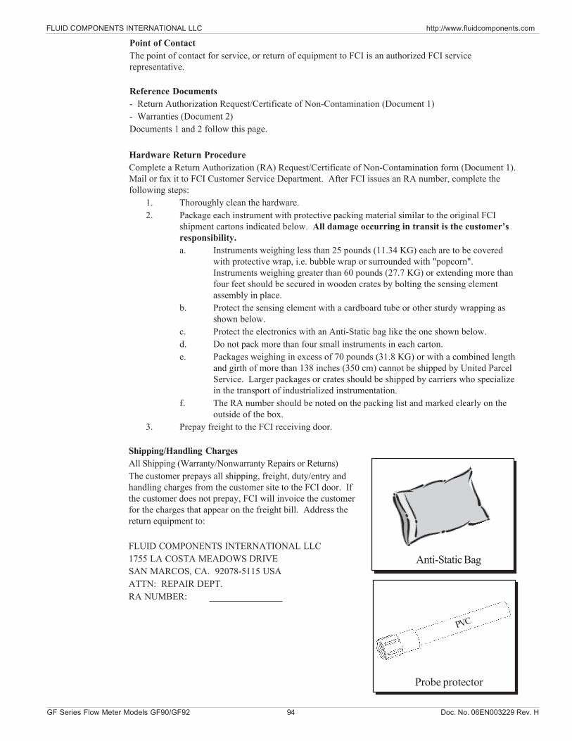
FLUID COMPONENTS INTERNATIONAL LLC http://www.fluidcomponents.com
GF Series Flow Meter Models GF90/GF92 94 Doc. No. 06EN003229 Rev. H
Hardware Return ProcedureComplete a Return Authorization (RA) Request/Certificate of Non-Contamination form (Document 1).Mail or fax it to FCI Customer Service Department. After FCI issues an RA number, complete thefollowing steps:
1. Thoroughly clean the hardware.2. Package each instrument with protective packing material similar to the original FCI
shipment cartons indicated below. All damage occurring in transit is the customer’sresponsibility.a. Instruments weighing less than 25 pounds (11.34 KG) each are to be covered
with protective wrap, i.e. bubble wrap or surrounded with "popcorn".Instruments weighing greater than 60 pounds (27.7 KG) or extending more thanfour feet should be secured in wooden crates by bolting the sensing elementassembly in place.
b. Protect the sensing element with a cardboard tube or other sturdy wrapping asshown below.
c. Protect the electronics with an Anti-Static bag like the one shown below.d. Do not pack more than four small instruments in each carton.e. Packages weighing in excess of 70 pounds (31.8 KG) or with a combined length
and girth of more than 138 inches (350 cm) cannot be shipped by United ParcelService. Larger packages or crates should be shipped by carriers who specializein the transport of industrialized instrumentation.
f. The RA number should be noted on the packing list and marked clearly on theoutside of the box.
3. Prepay freight to the FCI receiving door.
Shipping/Handling ChargesAll Shipping (Warranty/Nonwarranty Repairs or Returns)The customer prepays all shipping, freight, duty/entry andhandling charges from the customer site to the FCI door. Ifthe customer does not prepay, FCI will invoice the customerfor the charges that appear on the freight bill. Address thereturn equipment to:
FLUID COMPONENTS INTERNATIONAL LLC1755 LA COSTA MEADOWS DRIVESAN MARCOS, CA. 92078-5115 USAATTN: REPAIR DEPT.RA NUMBER:
PVC
Probe protector
Anti-Static Bag
Point of ContactThe point of contact for service, or return of equipment to FCI is an authorized FCI servicerepresentative.
Reference Documents- Return Authorization Request/Certificate of Non-Contamination (Document 1)- Warranties (Document 2)Documents 1 and 2 follow this page.
Doc. No. 06EN003229 Rev. H 95 GF Series Flow Meter Models GF90/GF92
FLUID COMPONENTS INTERNATIONAL LLC http://www.fluidcomponents.com
Warranty Repairs or ReturnsFCI prepays ground transportation charges for return of freight to the customer’s door. FCIreserves the right to return equipment by the carrier of our choice.International freight, handling charges, duty/entry fees for return of equipment are paid by thecustomer.
Non-Warranty Repairs or ReturnsFCI returns repaired equipment to the customer either collect or prepaid and adds freight chargesto the customer invoice.
Return to Stock EquipmentThe customer is responsible for all shipping and freight charges for equipment that is returned toFCI stock from the customer site. These items will not be credited to customer’s account untileither all freight charges are cleared or until the customer agrees to have any freight costs incurredby FCI deducted, along with applicable return to stock charges, from the credit invoice.(Exceptions are made for duplicate shipments made by FCI.)If any repair or return equipment is received at FCI, freight collect, without prior factory consent,FCI bills the sender for these charges.
Field Service ProceduresContact an FCI field representative to request field service.A field service technician is dispatched to the site from either the FCI factory or one of the FCIrepresentative offices. After the work is complete, the technician completes a preliminary fieldservice report at the customer site and leaves a copy with the customer.Following the service call, the technician completes a formal, detailed service report. The formalreport is mailed to the customer within five days of the technician’s return to the factory or office.
Field Service RatesAll field service calls are billed at the prevailing rates as listed in the FCI Price Book unlessspecifically excepted by the FCI Customer Service Manager. FCI reserves the right to bill fortravel times at FCI’s discretion.Customers are charged for shipping costs related to the transfer of equipment to and from the jobsite. They are also invoiced for field service work and travel expenses by FCI’s AccountingDepartment.
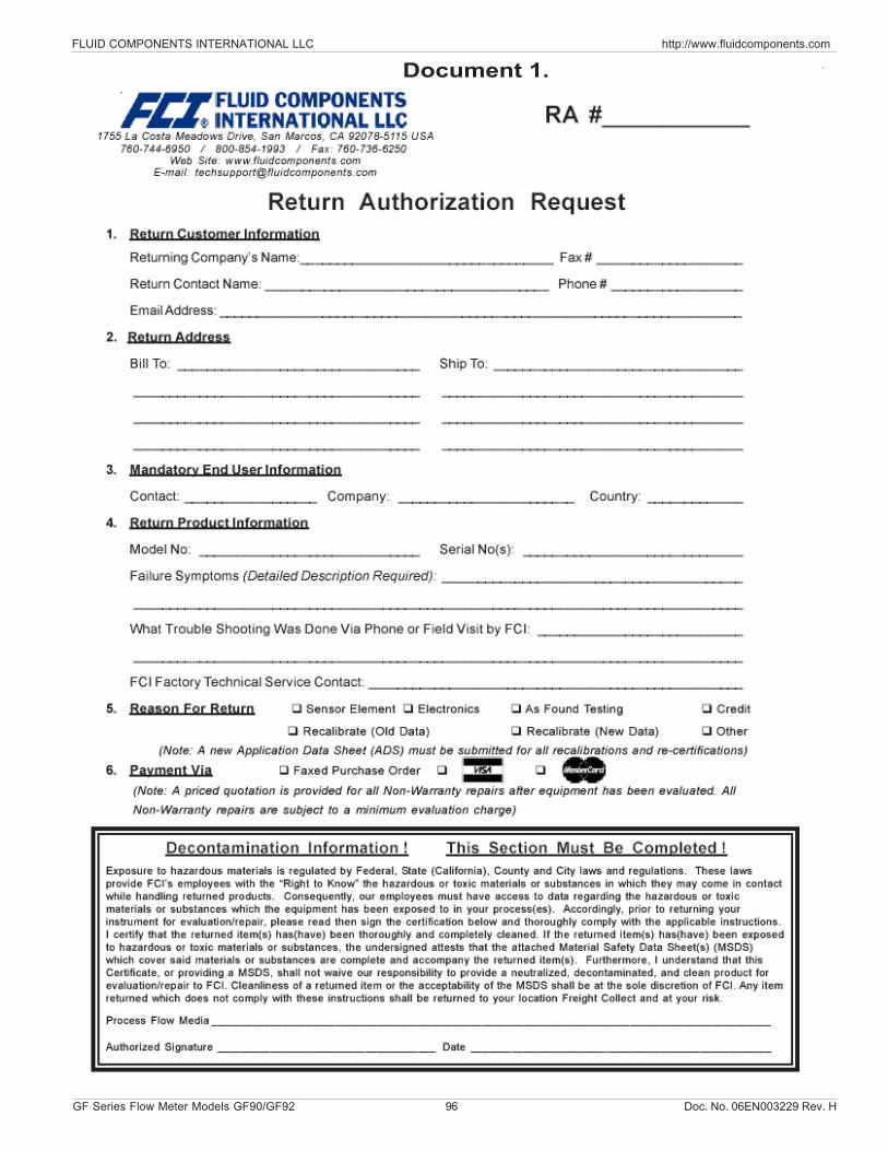
FLUID COMPONENTS INTERNATIONAL LLC http://www.fluidcomponents.com
GF Series Flow Meter Models GF90/GF92 96 Doc. No. 06EN003229 Rev. H
Document 1.
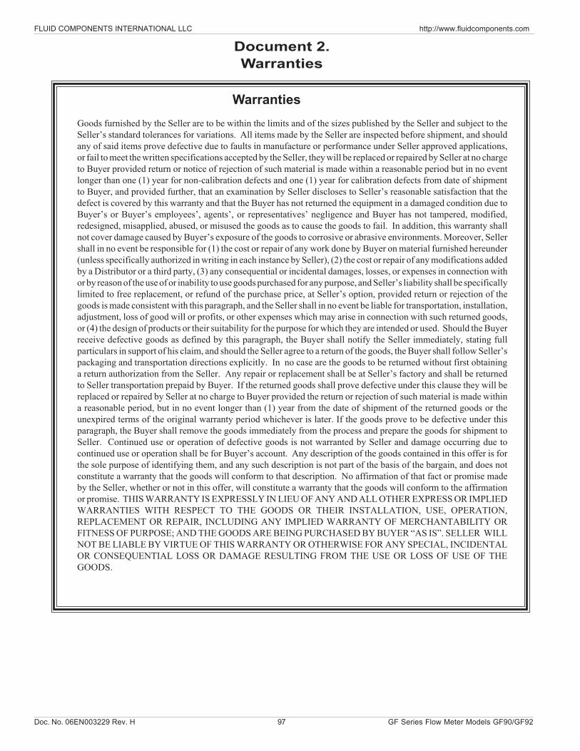
Doc. No. 06EN003229 Rev. H 97 GF Series Flow Meter Models GF90/GF92
FLUID COMPONENTS INTERNATIONAL LLC http://www.fluidcomponents.com
WarrantiesGoods furnished by the Seller are to be within the limits and of the sizes published by the Seller and subject to theSeller’s standard tolerances for variations. All items made by the Seller are inspected before shipment, and shouldany of said items prove defective due to faults in manufacture or performance under Seller approved applications,or fail to meet the written specifications accepted by the Seller, they will be replaced or repaired by Seller at no chargeto Buyer provided return or notice of rejection of such material is made within a reasonable period but in no eventlonger than one (1) year for non-calibration defects and one (1) year for calibration defects from date of shipmentto Buyer, and provided further, that an examination by Seller discloses to Seller’s reasonable satisfaction that thedefect is covered by this warranty and that the Buyer has not returned the equipment in a damaged condition due toBuyer’s or Buyer’s employees’, agents’, or representatives’ negligence and Buyer has not tampered, modified,redesigned, misapplied, abused, or misused the goods as to cause the goods to fail. In addition, this warranty shallnot cover damage caused by Buyer’s exposure of the goods to corrosive or abrasive environments. Moreover, Sellershall in no event be responsible for (1) the cost or repair of any work done by Buyer on material furnished hereunder(unless specifically authorized in writing in each instance by Seller), (2) the cost or repair of any modifications addedby a Distributor or a third party, (3) any consequential or incidental damages, losses, or expenses in connection withor by reason of the use of or inability to use goods purchased for any purpose, and Seller’s liability shall be specificallylimited to free replacement, or refund of the purchase price, at Seller’s option, provided return or rejection of thegoods is made consistent with this paragraph, and the Seller shall in no event be liable for transportation, installation,adjustment, loss of good will or profits, or other expenses which may arise in connection with such returned goods,or (4) the design of products or their suitability for the purpose for which they are intended or used. Should the Buyerreceive defective goods as defined by this paragraph, the Buyer shall notify the Seller immediately, stating fullparticulars in support of his claim, and should the Seller agree to a return of the goods, the Buyer shall follow Seller’spackaging and transportation directions explicitly. In no case are the goods to be returned without first obtaininga return authorization from the Seller. Any repair or replacement shall be at Seller’s factory and shall be returnedto Seller transportation prepaid by Buyer. If the returned goods shall prove defective under this clause they will bereplaced or repaired by Seller at no charge to Buyer provided the return or rejection of such material is made withina reasonable period, but in no event longer than (1) year from the date of shipment of the returned goods or theunexpired terms of the original warranty period whichever is later. If the goods prove to be defective under thisparagraph, the Buyer shall remove the goods immediately from the process and prepare the goods for shipment toSeller. Continued use or operation of defective goods is not warranted by Seller and damage occurring due tocontinued use or operation shall be for Buyer’s account. Any description of the goods contained in this offer is forthe sole purpose of identifying them, and any such description is not part of the basis of the bargain, and does notconstitute a warranty that the goods will conform to that description. No affirmation of that fact or promise madeby the Seller, whether or not in this offer, will constitute a warranty that the goods will conform to the affirmationor promise. THIS WARRANTY IS EXPRESSLY IN LIEU OF ANY AND ALL OTHER EXPRESS OR IMPLIEDWARRANTIES WITH RESPECT TO THE GOODS OR THEIR INSTALLATION, USE, OPERATION,REPLACEMENT OR REPAIR, INCLUDING ANY IMPLIED WARRANTY OF MERCHANTABILITY ORFITNESS OF PURPOSE; AND THE GOODS ARE BEING PURCHASED BY BUYER “AS IS”. SELLER WILLNOT BE LIABLE BY VIRTUE OF THIS WARRANTY OR OTHERWISE FOR ANY SPECIAL, INCIDENTALOR CONSEQUENTIAL LOSS OR DAMAGE RESULTING FROM THE USE OR LOSS OF USE OF THEGOODS.
Document 2.Warranties

FLUID COMPONENTS INTERNATIONAL LLC http://www.fluidcomponents.com
GF Series Flow Meter Models GF90/GF92 98 Doc. No. 06EN003229 Rev. H
Notice of Proprietary RightsThis document contains confidential technical data, including trade secrets and proprietary information which is the property of Fluid ComponentsInternational LLC (FCI). Disclosure of this data to you is expressly conditioned upon your assent that its use is limited to use within your company only(and does not include manufacture or processing uses). Any other use is strictly prohibited without the prior written consent of FCI.
Visit FCI on the Worldwide Web: www.fluidcomponents.com 1755 La Costa Meadows Drive, San Marcos, California 92078 USA - 760-744-6950 - 800-854-1993 - Fax 760-736-6250
FCI’s Complete Customer Commitment. WorldwideISO 9001:2000 and AS9100 Certified