Embed Size (px)
Citation preview
* Lead Free
Keep this manual near this appliance for future reference whenever maintenance or service is required.* The wetted surface of this product contacted by consumable water contains
less than one quarter of one percent (0.25%) of lead by weight.
GF 200 Installation ManualCombination gas-fired, condensinginstantaneous hot water heater and space heating fan coil
WARNINGThis appliance (GF 200) is a combination gas-fired, condensing, instantaneous hot water heater and space heating fan coil. The water heater is a CSA-certified product in its own right and, as such, must be installed according to its installation and operation manuals (supplied). This manual provides installation instructions for the GF 200, but defers to the water heater’s manual(s) where appropriate. Throughout, in any conflict between instructions from this manual and those from the water heater’s, the latter are assumed to be correct. When reading the water heater’s manual, only sections pertaining to the NPE-240A model may apply.
If the information in these instructions is not followed exactly, a fire or explosion may result, causing property damage, personal injury or death.
Do not store or use gasoline or other flammable vapors and liquids in the vicinity of this or any other appliance.What to do if you smell gas
● Do not try to light any appliance. ● Do not touch any electrical switch; do not use any phone in your building. ● Immediately call your gas supplier from a neighbor’s phone. Follow the gas supplier’s instructions. ● If you cannot reach your gas supplier, call the fire department.
Installation and service must be performed by a qualified installer, service agency or the gas supplier.The installation must conform with local codes or, in the absence of local codes, the National Fuel Gas Code, ANSIZ223.1/NFPA 54 and/or CSA B149.1, Natural Gas and Propane Installation Code.When applicable, the installation must conform with the Manufactured Home Construction and Safety Standard, Title 24 CFR, Part 3280 and/or CAN/CSA Z240 MH Series, Mobile Homes.

2
1. Important Information 3 1.1 Safety Information 3
2. About the Appliance 5 2.1 Items Included 52.2 Specifications 6
2.3 Front Panel 7
2.4 Components 8
2.5 Dimensions 9
2.6 Rating Plate 10
3. Installing the Appliance 11
3.1 Choosing an Installation Location 11
3.2 Installation Clearances 12
3.3 Ducting the Appliance 12
3.4 Connecting the Water Supply 14
3.5 Connecting the Condensate Drain 16
3.6 Connecting the Gas Supply 18
3.7 Venting the Appliance 20
3.8 Connecting the Electrical 21
3.9 Configuring the Appliance 23
4. Appendices 27
4.1 Blower Performance 27
4.2 Wiring Diagram 28
4.3 Ladder Diagram 29
4.4 Component Diagrams and Parts Lists 31
4.5 Installation Checklist 35
4.6 Troubleshooting 36
Contents
1.1 Safety Information
The following safety symbols are used in this manual. Read and follow all safety instructions in this manual precisely to avoid unsafe operating conditions, fire, explosion, property damage, personal injury, or death.
DANGER
Indicates an imminently hazardous situation which, if not avoided, could result in severe injury or death.
WARNING
Indicates a potentially hazardous situation which, if not avoided, could result in injury or death.
If you smell gas: ● Do not try to light any appliance. ● Do not touch any electrical switches or use
landline phones. ● From a neighbor’s phone, call your gas provider
and follow their instructions. ● If you cannot reach your gas provider, call the fire
department.
Do not use or store flammable products, such as gasoline, solvents, or adhesives in the same room or area as the appliance.
● The appliance has a main burner flame that can turn on at any time and can ignite flammable vapors. Vapors from flammable liquids can explode and catch fire, causing death or severe burns.
● Vapors cannot be seen and may be heavier than air. They can travel long distances along the ground and can be carried from other rooms to the appliance's main burner flame by air current.
● Keep all flammable products far away from the appliance and store them in approved containers. Keep the containers closed tightly and out of the reach of children and pets.
DANGER
3
This appliance (GF 200) is a combination gas-fired, condensing, instantaneous hot water heater and space heating fan coil. The water heater is a CSA- certified product in its own right and, as such, must be installed according to its installation and operation manuals ( ; supplied).
This manual provides installation instructions for the GF 200, but defers to the water heater manuals where appropriate. Throughout, in any conflict between instructions from this manual and those from the water heater’s, the latter are assumed to be correct. When reading the water heater manuals, only those sections pertaining to the NPE-240A model may apply.
As part of the GF 200’s manufacturing process, certain portions of the water heater’s installation have been completed. As such, some sections of this manual differ significantly from the corresponding instructions in the water heater manuals. In these sections, it is intended that the installer follow the specific instructions as described for the GF 200, while following the general instructions in the
water heater manuals.
Installation and service must be performed by a qualified installer, service agency, or the gas supplier.Failure to follow these and other included instructions exactly could result in a fire or explosion, causing property damage, personal injury, or death.
1. Important InformationCAUTION
Indicates a potentially hazardous situation which, if not avoided, could result in property damage.

● Do not store or use gasoline or other flammable liquids near this appliance. Doing so may result in fire or explosion.
● Do not place combustibles, such as newspapers or laundry, near the appliance or venting system. Doing so may result in a fire.
● Do not place or use hair sprays, spray paints, or any other compressed gases near the appliance or venting system, including the vent termination. Doing so may result in fire or explosion.
● Do not remove the front cover unless the power to the appliance is turned off or disconnected. Failure to do so may result in electric shock.
● Do not operate the appliance with the front cover opened. Doing so may result in fire or carbon monoxide (CO) poisoning, which may result in property damage, personal injury, or death.
● Do not operate this appliance without proper venting. Doing so may result in fire or carbon monoxide (CO) poisoning, which may result in property damage, personal injury, or death.
● Do not touch the internal components of the appliance with wet hands.Doing so may result in electric shock.
● Do not turn on the appliance unless the water and gas supplies are fully opened. Doing so may damage the appliance.
● Do not turn on the water if the cold water supply shut-off valve is closed. Doing so may damage the appliance.
● Do not use this appliance for anything other than its intended purpose, as described in this manual.
● When servicing the controls, label all wires prior to disconnecting them. Failure to do so may result in wiring errors, which can lead to improper or dangerous operation. Verify proper operation after servicing.
● Do not use unapproved replacement or accessory parts. Doing so may result in improper or dangerous operation and will void the manufacturer’s warranty.
● Do not place anything in or around the vent terminals, such as a clothes line, that could obstruct the air flow in or out of the appliance.
● This appliance has been approved for use in the USA and Canada only. Using the appliance in any other country will void the manufacturer’s warranty.
WARNING CAUTION
4
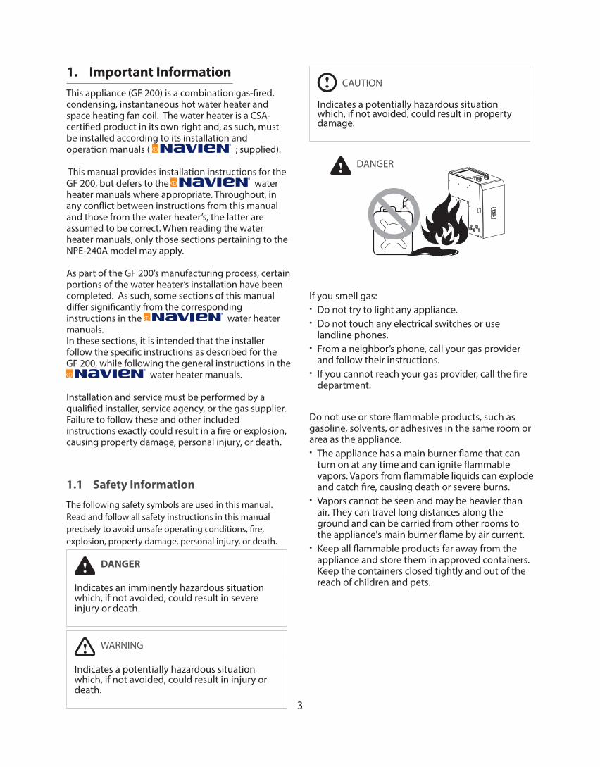
Kit Box, including: Item Part No. Qty
Open Brass Connection Adapter 85372 2
Plug Brass Connection Adapter 85523 2
Pipe Clips 85371 4
Flow Switch
CheckValve
ExpansionTank
Cold WaterSupply
DHW Supply
Space HeatingSupply
Heat DemandOutput
Thermostat
Outdoor Sensor
NPE-A SeriesWater Heater
Space HeatingReturn
Mixing Valve
Flow Switch 85582 1
Vinyl Tubing (10.5") 83044 1
O-Rings 85369 6
Screws 82998 14
2" Vent Termination Caps
2" Wall Flanges
85590
85591
2
4
Jumper 85742 1
Fuse (2 A; blade) 83517 1
Quick Installation Guide 85899 1
2. About the Appliance
2.1 Items Included
When you open the packaging, you will find the following items with the appliance. Check for each of the following items before installing the appliance. The manual packet and kit box can be found inside the front cover.
GF 200Installation Manual
Clearances [Dégagements]
GF 200
COMBINATION GAS WATER HEATER / CENTRAL AIR HEATING
*COMBINAISON CHAUFFEE-EAU INSTANTANE / GENERATEUR
D'AIR CHAUD
#####
Made in Canada
Fabriques au CanadaSerial Number: #####
##########
##### #####
AIR FLOW
This appliance is approved for upflow installation.
Cette fournaise est approvee pour l'installation et circulation d'air ascendente.
Min. clearance to combustible construction: (in.) see diagram.
Degagements minimum entre l'appareil et des constructions combustibles (PO.)
Vent clearance to combustible construction (in.): 0
Degagement de vent constructions combustibles (PO.): 0
* Min service clearance
* Degagement min. pour fins d'entretien pour les installations
C: COMBUSTIBLE FLOORS
Refer to Installation Manual for service clearance details 0
0
0
0
24*C
Electrical Rating / Caracteristique Electrique
VOLTS FREQ. PHASE MCA MAX. CKT. BRK INDOOR BLOWER MOTOR
120 60 Hz 1 13 A
9.6 A
3/4
FLA
HP
Certified byCertifie par
NY Thermal Inc. 30 Stonegate Dr., Saint John, NB, E2H 0A4, Canada
Model[Modele] Fuel[Gaz] Altitude, ft[Altitude, pi] Input, MBH[Entrée, kW]Min Max Space HeatingCapacity, MBH[Capacite deChauffage, kW]
Nat.
19.9 [5.83] 200 [58.61]
0 - 4500*
TGF-200
LP
DHW HeatingCapacity, MBH[Capacite de DHWChauffage, kW]
80 [23.45]
200 [58.61]
FACTORY SET FOR NATURAL GAS
Field converted to Propane Gas
CONFIGURÉE A L'USINE POUR GAZ NATUREL
Convertie au propane sur place
Date:________________________________ Date:________________________________
Gas Pressure [Pression du Gaz]
Natural [Naturel] Propane
Maximum Inlet Gas Pressure [Pression maximale d'entrée du gaz]
Minimum Inlet Gas Pressure [Pression minimum d'entrée du gaz]
Manifold Pressure [Pression d'admission]
10.5" WC3.5" WC-0.58" WC 13" WC8" WC-0.02 / -0.78" WC
Important Information [Rensignesments Importants]
� Use for Natural or LP Gas only.
� Maximum Water Pressure = 150 psi
� Maximum Static Pressure = 0.8 IN. W.C.
� Maximum Inlet Water Temperature = 180°F
� This appliance must be installed in accordance
with local codes, if any; if not, follow ANSI
Z223.1/NFPA 54 or CAN/CSA B149.1, Natural
Gas and Propane Installation Code, as
applicable. � Utilisez des gaz Naturel ou LP seulement.
� Pression d'eau max. = 150 lb/po²
� Pression statique max. = 0.8 PO. D'EAU
� Temp. maximale d'eau d'entrée = 180°F
� Cet appareil doit être installé conformément aux codes
locaux , le cas échéant ; sinon, suivez ANSI Z223.1 /
NFPA 54 ou CAN / CSA B149.1, gaz naturel et
propane Code d'installation, le cas échéant.
FOR YOUR SAFETY
Do not store or use gasoline or other
flammable vapors and liquids in the vicinity
of this or any other appliance. POUR VOTRE SÉCURITÉ
Ne pas entreposer ou utiliser d'essence ou d'autres
vapeurs et liquides inflammables à proximité de cet
appareil ou de tout autre appareil.
Standard ANSI Z21.10.3 / CSA 4.3
Gas Water Heaters, Volume III Storage Water
Heaters, with Input Ratings Above 75,000 BTU
per Hour, Circulating and Instantaneous
CSA C22.2 No. 236 / UL 1995
Heating and Cooling Equipment
* Refer to water heater rating plate under access panel on the opposite side of this cabinet.
� Orifices necessary for LP conversion are provided.
� Failure to use the correct gas can cause problems
which can result in death, serious injury or property
damage
� Les injectures necessaires a la conversion au GPL sont
fournis.� Le fait de ne pas utiliser le bon gaz peut causer des
problemes qui peuvent mener a la mort, causer des bessures
graves ou endommager la propriete
24*24*
Water heater rating plate located under access panel on opposite side of cabinet.
20 A
GF 200 Installation Manual
Water Heater Installation &
Operation Manuals
LP Conversion Kit
(inside the cabinet)
Spare Parts Kit
(inside the cabinet)
5

2.2 Specifications
The following table lists the specifications for the appliance. Additional specifications about water, gas, electric, and air supplies (venting) appear in the Installation section.
Specifications GF 200
Heat Capacity (Input)
Natural Gas (NG) Space Heating: 19,900 – 80,000 BTU/H
DHW Heating: 19,900 – 199,000 BTU/HPropane Gas (LP)
Energy Efficiency
AFUE 97.1
UEF (NG & LP) 0.96
EF (Canada) (NG & LP) 0.97
Flow Rate (DHW)
50°F (28°C) Temp Rise 7.8 GPM (30 L/m)
65°F (36°C) Temp Rise 6.1 GPM (23 L/m)
80°F (44°C) Temp Rise 5.0 GPM (19 L/m)
Dimensions 173/4 in (W) x 38 in (H) x 38 in (D)
Weight 248 lbs
Installation Type Indoor
Venting Type Forced Draft Direct Vent
Ignition Electronic Ignition
Water Pressure 15 – 150 PSI
Gas Supply Pressure (from source)
NG 3.5 – 10.5 in w.c.See Water Heater Installation Manual (Supplied)
LP 8 – 13 in w.c.
Gas Manifold Pressure (min-max)
NG -0.05 – -0.58 in w.c.
LP -0.10 – -0.78 in w.c.
Minimum Flow Rate* 0.5 GPM (1.9 L/m); < 0.01 GPM (0.04 L/m) with recirculation mode (factory default)*
Connection Sizes
Cold Water Inlet 3/4 in sweat joint
Hot Water Outlet 3/4 in sweat joint
Gas Inlet 3/4 in NPT
Power Main Supply 120 V AC, 60 Hz
Materials
Casing Cold Rolled Carbon Steel
Heat ExchangersPrimary: Stainless SteelSecondary: Stainless SteelTertiary: Copper (tubes); Aluminum (fins)
Interconnecting piping Stainless steel, Copper, Brass (low-lead), Polymers (Viton™, EPDM, etc.)
Venting**
Size 2 in 3 in
See Water Heater Installation Manual (Supplied)
Length (max.) 60 ft 150 ft
No. of elbows (max). 6(8 ft per 90°)
8(5 ft per 90°)
Materials CPVC, Polypropylene, PVC**Special Gas Vent Type BH (Class II, A/B/C)
Safety Devices
Flame Rod, APS, Ignition Operation Detector, Water Temperature High Limit Switch, Exhaust Temperature High Limit Sensor, Power Surge Fuse, Door Interrupt Switches, Coil Freeze-protection Alogorithm, Anti-stagnation Sequence.
*Energy consumption may increase when the system is configured for recirculation. **High temperature venting material may be required. See 'Section 3.7 – Venting the Appliance' for details.
6

a
b
c
d
e
f
g
h
i
j
k
2.3 The Front PanelThe front panel allows you to adjust the water temperature and view the operating status or error codes.
a
Error
g
N/A
A code will appear on the display
b
Hot Water Recirculation h
DisplayIndicates Recirculation Mode (or pump activity)
c
Diagnostics button
i
Up button
For installers only Increases the temperature (or navigates through menus)
d
Information button
j
Down button
Shows basic information (Inlet temp., Outlet temp., Flow rate)
Decreases the temperature (or navigates through menus)
e
Reset button
k
Power button
Resets the water heater from error state (or returns to previous menu)
Turns the water heater on or off (press and hold for 1-2 seconds)
f
Combustion
Indicates when the gas burner is on
7

2.4 Components
The following diagram shows the key components of the appliance. Component assembly diagrams and particular parts lists are included in the Appendixes.
Intake Air Duct
Exhaust Duct
Exhaust Limit Temperature Sensor
Exhaust Body
Ignition Transformer
Burner
Primary Heat Exchanger
Secondary Heat Exchanger
Flow Sensor
Condensate Trap
Front Panel
PCB Box
Water Adjustment Valve
Water Inlet FilterCondensate Drain
Condensate Drain Lid
Combustion Fan Motor
Dual Venturi
Gas Pipe
APS (Air Pressure Sensor)
Buffer Tank
Circulation Pump
Gas Valve
Gas Inlet Fitting
DHW Inlet Fitting
Field Wiring Panel
Recirculation Inlet Fitting
GF 200
DHW Supply Fitting
3-Way Valve Service Valve
8
Controller
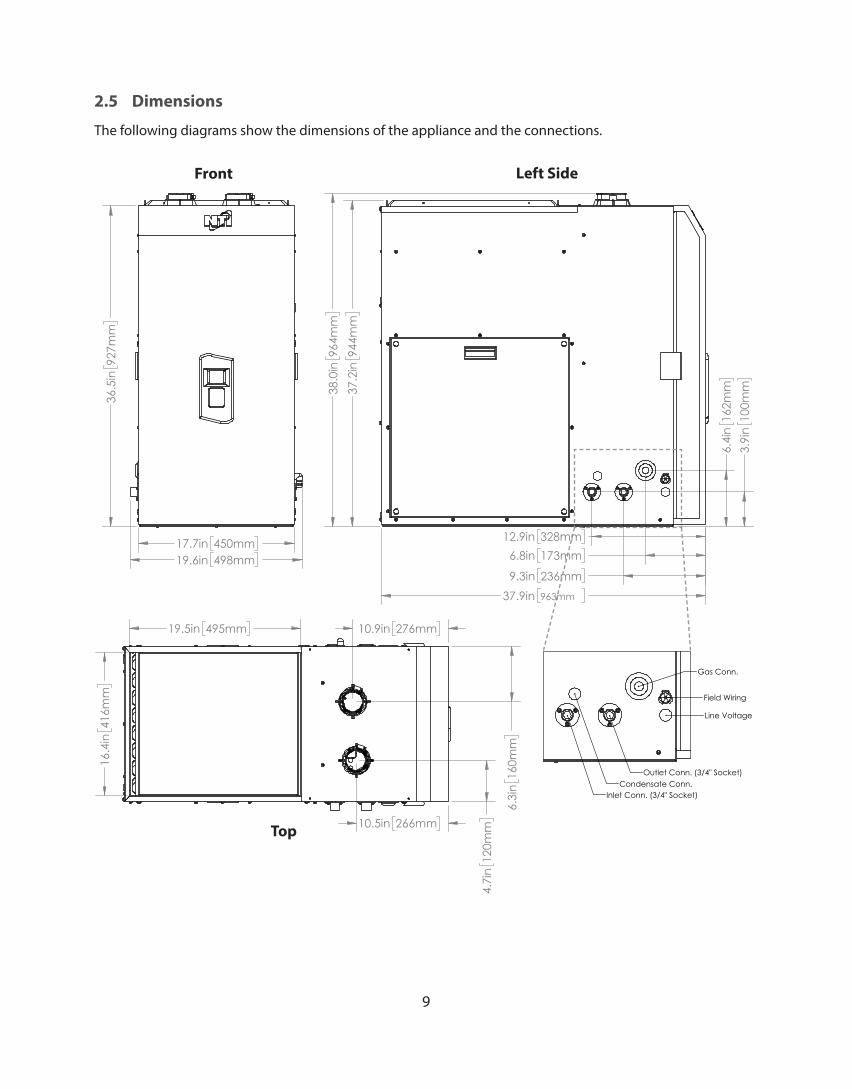
2.5 Dimensions
The following diagrams show the dimensions of the appliance and the connections.
19.5in 495mm
16.4
in41
6mm
10.9in 276mm
10.5in 266mm
6.3i
n16
0mm
4.7i
n12
0mm
36.5
in92
7mm
19.6in 498mm17.7in 450mm
37.2
in94
4mm
37.9in 963mm
9.3in 236mm
12.9in 328mm
3.9i
n10
0mm
6.4i
n16
2mm
6.8in 173mm
38.0
in96
4mm
Inlet Conn. (3/4" Socket)
Outlet Conn. (3/4" Socket)
Line Voltage
Field Wiring
Gas Conn.
Condensate Conn.
Front
Top
Left Side
9

2.6 Rating Plate
This appliance comes from the factory configured for use with Natural Gas (NG). Before starting the installation, check the rating plate located on the side of the appliance to ensure that it matches the gas type, gas pressure, water pressure, and electrical supply available in the installation location. If the appliance does not match each of these ratings, do not install the appliance. If conversion to Propane Gas is required, the included gas conversion kit must be used.
WARNING
● Be sure the gas type and electricity voltage match the rating plate. Using a different gas type will cause abnormal combustion and appliance malfunction.
● Using abnormally high or low AC voltage may cause abnormal operation, and may reduce the life expectancy of this product.
Rating Plate, *Plaque SignalétiqueDirect Vent Automatic Instantaneous Water Heater *Chauffe-eau instantané automatique à évent directFor Indoor, Outdoor or Manufactured Home (Mobile Home) Installation *Pour installation dans une maison préfabriquée (mobile)
Navien, Inc.20 Goodyear, Irvine, CA 92618Tel: 1-800-519-8794
Orifices necessary for LP conversion are provided. *Les injectures nécessaires à la conversion au GPL sont fournis.Failure to use the correct gas can cause problems which can result in death, serious injury or property damage. *Le fait de ne pasutiliser le bon gaz peut causer des problèmes qui peuvent mener à la mort, causer des blessures graves ou endommager la propriété.Consult your installation manual for more information. *Consultez votre manuel d’installation pour plus d’information.Suitable for combination water (potable) heating and space heating and not suitable for space heating applications only.*Convient au chauffage combiné de l’eau (potable) et des locaux, mais non au chauffage des locaux seulement.This appliance is certified for use at altitudes up to 4,500 ft (1,370 m) in accordance to the latest CAN/CGA 2.17-High Altitude Installationprocedures at normal manifold pressure. For installation instructions at altitudes higher than 4,500 ft, please contact Navien. *Cet appareilest certifié pour une utilisation à des altitudes de 0 à 4,500 pieds (1,370 m) conformément aux toutes les procédures d’installation à hautealtitude CAN/CGA 2.17 à une pression normale. Pour les installations à élévations en haut de 4,500 pieds, appeler le bureau de Navien.This appliance must be installed in accordance with local codes, or in the absence of local codes, the National Fuel Gas Code, ANSIZ223.1/NFPA 54 or the CSA B149.1, Natural Gas and Propane Installation Code. *Cet appareil doit être installé selon les règlementslocaux, ou en l’absence de tels règlements, selon le National Fuel Gas Code, ANSI Z223.1/NFPA 54, ou les, Code d'installation du gaznatural et du propane, CSA-B149.1.
Model No., *Numéro de modèleNPE-210AMax. Input Rating, *Entrée GPL max.180,000 Btu/hRecovery Rating, *Calibre de recouvrementMax. Inlet Gas Pressure, *Pression max. de gaz d’entréeMin. Inlet Gas Pressure, *Pression min. de gaz d’entréeManifold Pressure, *Pression d’admissionElectrical Rating, *Régime nominal électriqueMax. Water Pressure, *Pression d’eau max.
Type of Gas, *Type de gazNGMin. Input Rating, *Débit calorifique max.19,900 Btu/h265 Gallons/Hour, *gallons/heures10.5 Inches W.C. *pouces W.C.3.5 Inches W.C. *pouces W.C.-0.36 Inches W.C. *pouces W.C.AC *c.a. 120 Volts 60Hz, less than 2 amperes, *Utilise moins de 2A150 psi *lb/po2 ANSI Z21.10.3 · CSA 4.3-2011
FOR YOUR SAFETY *POUR VOTRE SÉCURITÉDo not store or use gasoline or other flammable vapors and liquids in the vicinity of this or any other gas appliances. *Ne rangezpas et n'utilisez pas d'essence ou d'autres liquides ou vapeurs inflammables près de cet appareil ou de tout autre appareil électroménager.
Clearances [Dégagements]
IFW-80-200
COMBINATION GAS WATER HEATER / CENTRAL AIR HEATING
*COMBINAISON CHAUFFEE-EAU INSTANTANE / GENERATEUR
D'AIR CHAUD
#####
Made in Canada
Fabriques au CanadaSerial Number: #####
##########
##########
AIR FLOW
This appliance is approved for upflow installation.
Cette fournaise est approvee pour l'installation et circulation d'air ascendente.
Min. clearance to combustible construction: (in.) see diagram.
Degagements minimum entre l'appareil et des constructions combustibles (PO.)
Vent clearance to combustible construction (in.): 0
Degagement de vent constructions combustibles (PO.): 0
* Min service clearance
* Degagement min. pour fins d'entretien pour les installations
C: COMBUSTIBLE FLOORS
Refer to Installation Manual for service clearance details
0
0
0
0
24*C
Electrical Rating / Caracteristique Electrique
VOLTS FREQ. PHASE MCA MAX. CKT. BRK
INDOOR BLOWER MOTOR
120
60 Hz
1
13 A
9.6 A
3/4
FLA
HP
Certified byCertifie par
NY Thermal Inc. 30 Stonegate Dr., Saint John, NB, E2H 0A4, Canada
Model[Modele] Fuel[Gaz] Altitude, ft[Altitude, pi] Input, MBH
[Entrée, kW]Min
MaxSpace Heating
Capacity, MBH
[Capacite de
Chauffage, kW]
Nat.
19.9 [5.83]200 [58.61]
0 - 4500*
IFW-80-200
LP
DHW Heating
Capacity, MBH
[Capacite de DHW
Chauffage, kW]
80 [23.45]
200 [58.61]
FACTORY SET FOR NATURAL GAS
Field converted to Propane Gas
CONFIGURÉE A L'USINE POUR GAZ NATUREL
Convertie au propane sur place
Date:________________________________
Date:________________________________
Gas Pressure [Pression du Gaz]
Natural [Naturel]
Propane
Maximum Inlet Gas Pressure [Pression maximale d'entrée du gaz]
Minimum Inlet Gas Pressure [Pression minimum d'entrée du gaz]
Manifold Pressure [Pression d'admission]
10.5" WC3.5" WC-0.58" WC13" WC8" WC-0.02 / -0.78" WC
Important Information [Rensignesments Importants]
� Use for Natural or LP Gas only.
� Maximum Water Pressure = 150 psi
� Maximum Static Pressure = 0.8 IN. W.C.
� Maximum Inlet Water Temperature = 180°F
� This appliance must be installed in accordance
with local codes, if any; if not, follow ANSI
Z223.1/NFPA 54 or CAN/CSA B149.1, Natural
Gas and Propane Installation Code, as
applicable. � Utilisez des gaz Naturel ou LP seulement.
� Pression d'eau max. = 150 lb/po²
� Pression statique max. = 0.8 PO. D'EAU
� Temp. maximale d'eau d'entrée = 180°F
� Cet appareil doit être installé conformément aux codes
locaux , le cas échéant ; sinon, suivez ANSI Z223.1 /
NFPA 54 ou CAN / CSA B149.1, gaz naturel et
propane Code d'installation, le cas échéant.
FOR YOUR SAFETY
Do not store or use gasoline or other
flammable vapors and liquids in the vicinity
of this or any other appliance.
POUR VOTRE SÉCURITÉ
Ne pas entreposer ou utiliser d'essence ou d'autres
vapeurs et liquides inflammables à proximité de cet
appareil ou de tout autre appareil.
Standard ANSI Z21.10.3 / CSA 4.3
Gas Water Heaters, Volume III Storage Water
Heaters, with Input Ratings Above 75,000 BTU
per Hour, Circulating and Instantaneous
CSA C22.2 No. 236 / UL 1995
Heating and Cooling Equipment
* Refer to water heater rating plate under access panel on the opposite side of this cabinet.
� Orifices necessary for LP conversion are provided.
� Failure to use the correct gas can cause problems
which can result in death, serious injury or property
damage
� Les injectures necessaires a la conversion au GPL sont
fournis.� Le fait de ne pas utiliser le bon gaz peut causer des
problemes qui peuvent mener a la mort, causer des bessures
graves ou endommager la propriete
24*24*
Water heater rating plate located under access panel on opposite side of cabinet.
20 A
** The Water Heater rating plate is located on the right side of the cabinet.
10
Clearances [Dégagements]
GF 200COMBINATION GAS WATER HEATER / CENTRAL AIR HEATINGCOMBINAISON CHAUFFEE-EAU INSTANTANE / GENERATEUR
D'AIR CHAUD
#####Made in Canada
Fabriques au Canada
Serial Number: #####
##### ##### ##### #####
AIR FLOWThis appliance is approved for upflow installation.Cette fournaise est approvée pour l'installation et circulation d'air ascendente.Min. clearance to combustible construction: (in.) see diagram.Dégagements minimum entre l'appareil et des constructions combustibles (PO.)Vent clearance to combustible construction (in.): 0Dégagement de vent constructions combustibles (PO.): 0* Min service clearance* Dégagement min. pour fins d'entretien pour les installations
C: COMBUSTIBLE FLOORS*Refer to Installation Manual for service clearance details
0
00
0
24*
C
Electrical Rating / Caractéristique Électrique
VOLTS INDOOR BLOWER MOTOR
120 60 Hz 1 12 A 9.6 A 3/4RATED AMPS HP
Certified byCertifie par
NY Thermal Inc. 30 Stonegate Dr., Saint John, NB, E2H 0A4, Canada
Model[Modèle]
Fuel[Gaz]
Altitude, ft[Altitude, pi]
Input, MBH[Entrée, kW]
Min Max
Space HeatingCapacity, MBH
[Capacité deChauffage, kW]
Nat.19.9 [5.83] 200 [58.6]0 - 4500*GF 200
LP80 [23.5]
FACTORY SET FOR NATURAL GASField converted to Propane Gas
CONFIGURÉE À L'USINE POUR GAZ NATURELConvertie au propane sur place
Date:________________________________ Date:________________________________
Gas Pressure [Pression du Gaz] Natural [Naturel] Propane
Maximum Inlet Gas Pressure [Pression maximale d'entrée du gaz]
Minimum Inlet Gas Pressure [Pression minimum d'entrée du gaz]
Manifold Pressure [Pression d'admission]
10.5" WC
3.5" WC
-0.58" WC
13" WC
8" WC
-0.02 / -0.78" WC
Important Information [Rensignesments Importants] Use for Natural or LP Gas only. Maximum Water Pressure = 150 psi Maximum Static Pressure = 0.8 IN. W.C. Maximum Inlet Water Temperature = 180°F This appliance must be installed in accordance
with local codes, if any; if not, follow ANSIZ223.1/NFPA 54 or CAN/CSA B149.1, NaturalGas and Propane Installation Code, asapplicable.
Utilisez des gaz Naturel ou LP seulement. Pression d'eau max. = 150 lb/po² Pression statique max. = 0.8 PO. D'EAU Temp. maximale d'eau d'entrée = 180°F Cet appareil doit être installé conformément aux codes
locaux, le cas échéant ; sinon, suivez ANSI Z223.1 /NFPA 54 ou CAN / CSA B149.1, gaz naturel etpropane Code d'installation, le cas échéant.
FOR YOUR SAFETYDo not store or use gasoline or otherflammable vapors and liquids in the vicinityof this or any other appliance.
POUR VOTRE SÉCURITÉNe pas entreposer ou utiliser d'essence ou d'autresvapeurs et liquides inflammables à proximité de cetappareil ou de tout autre appareil.
Standard ANSI Z21.10.3 / CSA 4.3Gas Water Heaters, Volume III Storage WaterHeaters, with Input Ratings Above 75,000 BTUper Hour, Circulating and Instantaneous
CSA C22.2 No. 236 / UL 1995Heating and Cooling Equipment
* Refer to water heater rating plate on the opposite side of this cabinet.
Orifices necessary for LP conversion are provided. Failure to use the correct gas can cause problems which can result in death, serious injury or property damage.
Les injectures nécessaires à la conversion au GPL sontfournis.
Le fait de ne pas utiliser le bon gaz peut causer desproblèmes qui peuvent mener à la mort, causer des blessuresgraves ou endommager la propriété.
24*
24*
Water heater rating plate located on opposite side of cabinet.
20 A
FREQ. PHASE MCA MAX. CKT. BRK.RATED AMPS
15 A
Part # 85477

3. Installing the appliance
3.1 Choosing an installation location
This appliance must be installed indoors, in a dry location free of dust and debris.
When choosing an installation location, you must ensure that the location provides adequate clearance for the appliance (including ductwork), adequate venting and drainage options, and sufficient access to gas, water, and electrical supplies. Carefully consider the following factors when choosing an installation location:
Water quality
The following table shows the maximum contaminant levels allowed, based on the EPA National Secondary Drinking Water Regulations (40 CFR Part 143.3). If you suspect that your water is contaminated in any way, discontinue use of the appliance and contact an authorized technician or licensed professional. Failure to do so could void the warranty.
Contaminant Maximum Allowable Level
Total Hardness Up to 200 mg/l (12 grains/gal.)
Aluminum 0.05 to 0.2 mg/l
Chloride Up to 250 mg/l
Copper Up to 1.0 mg/l
Iron Up to 0.3 mg/l
Manganese Up to 0.05 mg/l
pH 6.5 to 8.5
Sulfate Up to 205 mg/l
Total Dissolved Solids (TDS) Up to 500 mg/l
Zinc Up to 5 mg/l
Chlorine Up to 4 mg/l
Adequate drainage ● Maintain proper clearances from any openings in
the building. ● Install the appliance with a minimum clearance
of 12 in (300 mm) above an exterior grade, or as required by local codes.
● Maintain a minimum clearance of 4 ft (1.2 m) from heating and cooling vents.
● Do not enclose the vent termination. ● Install the exhaust vent in an area that is free from
obstructions and does not allow the exhaust to accumulate.
● Do not install the appliance where moisture from the exhaust may discolor or damage walls.
● Do not install the appliance in bathrooms, bedrooms, or any other occupied rooms that are normally kept closed or that are not adequately ventilated.
11
Proximity to fixtures and other appliances
Install the appliance near fixtures that deliver or use hot water, such as bathroom, kitchen, and laundry room faucets. Select a location that minimizes the water piping required between major fixtures. If the distances are long or the user requires “instant“ hot water, we recommend running a recirculation line back to the appliance from the furthest fixture. Insulate as much of the hot water supply and recirculation lines as possible.
Additionally, take care to locate the appliance such that the supply and return ductwork can be installed efficiently, to limit noise and power consumption.
Combustion air quality ● Do not install the appliance in areas where dust
and debris may accumulate or where hair sprays, spray detergents, chlorine, or similar chemicals are used.
● Do not install the appliance in areas where gasoline or other flammables are used or stored.
● Ensure that combustible materials are stored away from the appliance and that hanging laundry or similar items do not obstruct access to the appliance or its venting.
NTI recommends that the connections be made in the following order to ensure ease of installation, given the limited space in the piping cabinet:• Ductwork (could also be last)• Condensate drain• Domestic water (Inlet, then Outlet)• Gas supply• Electrical
3.2 Installation clearances
Install the appliance in an area that allows for service and maintenance access to utility connections, piping, filters, and traps. Based on the installation location, ensure the following clearances are maintained:
Minimum clearance: from combustibles
for service
Top 9 in as required
Back 0 0
Front 0* 0 | 24 in*
Side (w/o connections) 0 0 | as required
Side (w/ connections) 0 as required
Side (Blower access) 0 24 in
Bottom 0 0
* No clearance required to front of unit if obstruction is removable (such as a door or access panel). 24 inch clearance if obstruction is permanent.
Note The service clearances are recommendations. If you are unable to maintain those specific clearances, be sure you have an alternative plan as to how you are going to service the unit.
When locating the appliance prior to completing the ductwork and plumbing, it is essential that sufficient space be allotted for the installation and maintenance of components such as:
• Flow switch• Thermostatic Mixing Valve (TMV)• Pressure Relief Valve (PRV)• Shut off and drain valves• Expansion tank (optional)• Condensate drain (and optional pump)• Return air filter• Circulating blower
12
3.3 Ducting the appliance
3.3.1 Supply ducting
The GF 200 provides a standard-size flanged supply air outlet for easy installation of an evaporator coil or supply plenum. Take care not to damage the heating coil when installing ductwork to the supply air outlet by using screws no longer than 3/4” (0.75 in.).
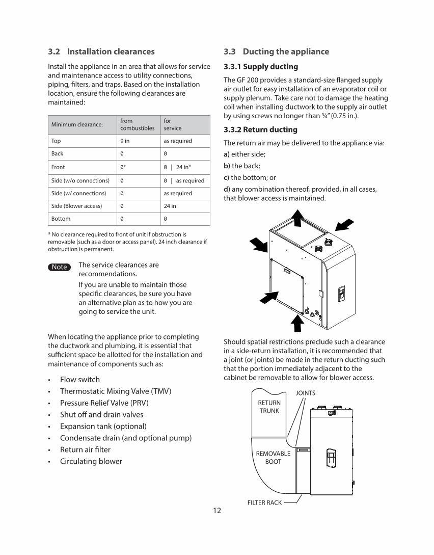
3.3.2 Return ducting
The return air may be delivered to the appliance via:
a) either side;
b) the back;
c) the bottom; or
d) any combination thereof, provided, in all cases, that blower access is maintained.
JOINTS
REMOVABLE BOOT
FILTER RACK
RETURN TRUNK
Should spatial restrictions preclude such a clearance in a side-return installation, it is recommended that a joint (or joints) be made in the return ducting such that the portion immediately adjacent to the cabinet be removable to allow for blower access.
1313
3.3.3 Air filtration systemIn all installations, an appropriate air filtration system is recommended and must meet test requirements in UL 900. Failure to install a filter could lead to damage to and/or premature failure of the space heating components.
In all cases, care must be taken to ensure that return ducting is sealed against the inlet, such that the entire airsteam is directed through the air filter. Failure to do so could cause damage to the air moving equipment and clogging of the heating and/or cooling coils.
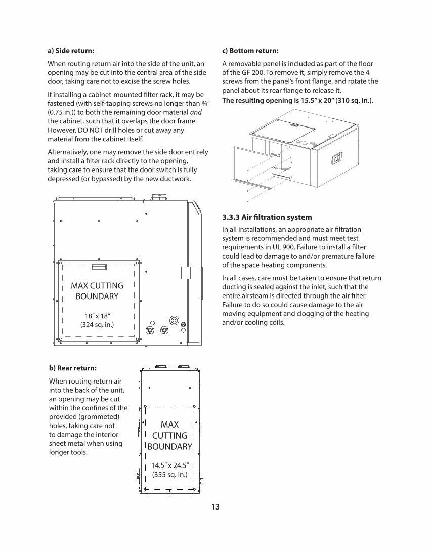
MAX CUTTING
BOUNDARY
14.5” x 24.5” (355 sq. in.)
MAX CUTTINGBOUNDARY
18” x 18” (324 sq. in.)
a) Side return:
When routing return air into the side of the unit, an opening may be cut into the central area of the side door, taking care not to excise the screw holes.
If installing a cabinet-mounted filter rack, it may be fastened (with self-tapping screws no longer than 3/4” (0.75 in.)) to both the remaining door material and the cabinet, such that it overlaps the door frame. However, DO NOT drill holes or cut away any material from the cabinet itself.
Alternatively, one may remove the side door entirely and install a filter rack directly to the opening, taking care to ensure that the door switch is fully depressed (or bypassed) by the new ductwork.
c) Bottom return:
A removable panel is included as part of the floor of the GF 200. To remove it, simply remove the 4 screws from the panel’s front flange, and rotate the panel about its rear flange to release it. The resulting opening is 15.5” x 20” (310 sq. in.).
b) Rear return:
When routing return air into the back of the unit, an opening may be cut within the confines of the provided (grommeted)holes, taking care not to damage the interior sheet metal when using longer tools.
3.4 Connecting the Water Supply
When connecting the water supply, follow these guidelines:
● Use only pipes, fittings, valves, and other components, such as solder, that are approved for use in potable water systems.
● Tighten the appliance connection valves and/or fittings with care to avoid damage.
● We recommend using unions and manual shut-off valves on the cold water inlet and DHW outlet.
● Strive to make the hot water piping system as short as possible, to deliver hot water to the fixtures more quickly.
● To conserve water and energy, insulate all DHW piping. Never cover the drain or pressure relief valve. If the appliance is installed in a closed water supply system, such as one having a backflow preventer in the cold water supply line, means must be provided to control thermal expansion. Contact the water supplier or local plumbing inspector for information about how to control this situation.
● After installing the appliance, clean the inlet water filter that is located inside the cold water inlet, and then test the appliance for proper flow and inspect for leaks. Instruct the appliance owner that the filter must be cleaned periodically to maintain proper water flow.
14
3.4.1 Installing the plumbing connections
1. A kit box containing the necessary plumbing connections is shipped inside the front cover.
2. This appliance is shipped with cardboard inserts on the inside to support the plumbing during shipping. Remove cardboard prior to installation.
REMOVE CARDBOARD
3. Determine which side of the appliance the inlet and outlet water connections will be made on.
A) Left side connectionsB) Right side connectionsC) Both - One on each side
Note Typically both water connections are installed on the opposite side of the return air duct to allow for air filter & maintenance clearances.
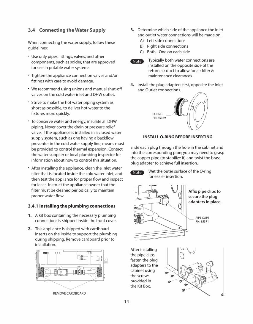
4. Install the plug adapters first, opposite the Inlet and Outlet connections.
INSTALL O-RING BEFORE INSERTING
Slide each plug through the hole in the cabinet and into the corresponding pipe; you may need to grasp the copper pipe (to stabilize it) and twist the brass plug adapter to achieve full insertion.
O-RINGPN: 85369
Note Wet the outer surface of the O-ring for easier insertion.
PIPE CLIPSPN: 85371
Affix pipe clips to secure the plug adapters in place.
After installing the pipe clips, fasten the plug adapters to the cabinet using the screws provided in the Kit Box.
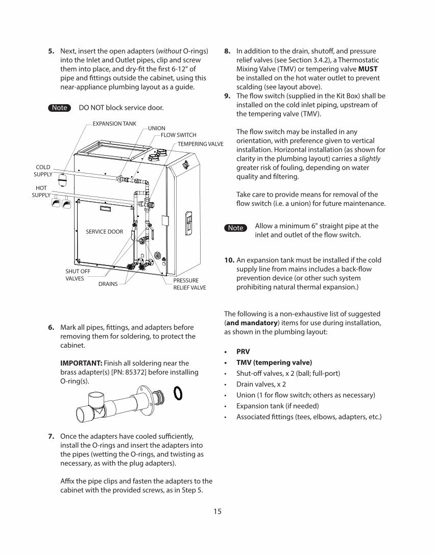
8. In addition to the drain, shutoff, and pressure relief valves (see Section 3.4.2), a Thermostatic Mixing Valve (TMV) or tempering valve MUST be installed on the hot water outlet to prevent scalding (see layout above).
9. The flow switch (supplied in the Kit Box) shall be installed on the cold inlet piping, upstream of the tempering valve (TMV). The flow switch may be installed in any orientation, with preference given to vertical installation. Horizontal installation (as shown for clarity in the plumbing layout) carries a slightly greater risk of fouling, depending on water quality and filtering. Take care to provide means for removal of the flow switch (i.e. a union) for future maintenance.
5. Next, insert the open adapters (without O-rings) into the Inlet and Outlet pipes, clip and screw them into place, and dry-fit the first 6-12" of pipe and fittings outside the cabinet, using this near-appliance plumbing layout as a guide.
6. Mark all pipes, fittings, and adapters before removing them for soldering, to protect the cabinet. IMPORTANT: Finish all soldering near the brass adapter(s) [PN: 85372] before installing O-ring(s).
COLDSUPPLY
HOT SUPPLY
UNIONFLOW SWITCH
TEMPERING VALVE
SHUT OFFVALVES
DRAINS
SERVICE DOOR
PRESSURERELIEF VALVE
EXPANSION TANK
15
Note DO NOT block service door.
7. Once the adapters have cooled sufficiently, install the O-rings and insert the adapters into the pipes (wetting the O-rings, and twisting as necessary, as with the plug adapters). Affix the pipe clips and fasten the adapters to the cabinet with the provided screws, as in Step 5.
Note Allow a minimum 6" straight pipe at the inlet and outlet of the flow switch.
10. An expansion tank must be installed if the cold supply line from mains includes a back-flow prevention device (or other such system prohibiting natural thermal expansion.)
The following is a non-exhaustive list of suggested (and mandatory) items for use during installation, as shown in the plumbing layout:
• PRV• TMV (tempering valve)• Shut-off valves, x 2 (ball; full-port)• Drain valves, x 2• Union (1 for flow switch; others as necessary)• Expansion tank (if needed)• Associated fittings (tees, elbows, adapters, etc.)

16
3.4.2 Connecting a Pressure Relief Valve
WARNING
Improper installation of the pressure relief valve may result in property damage, personal injury, or death. Follow all instructions and guidelines when installing the pressure relief valve. The valve should be installed only by a licensed professional.
To complete the installation of the appliance, you must install an approved 3/4 in, maximum 150 PSI pressure relief valve on the hot water outlet. The appliance's water heater has a built-in high temperature shut off switch, so install a “pressure only“ relief valve. This valve is not supplied, but is required. The following examples are approved for use with the appliance:
● Wilkins P-1000A (Zurn Industries) ● Conbraco 17-402-04 ● Watts Industries 3L(M7) ● Cash Acme FWL-2, 3/4 in
The pressure relief valve should be placed as close to the hot water outlet as possible. No other valve shall be placed between the pressure relief valve and the appliance.
PressureRelief Valve
When installing the valve, follow these guidelines: ● Ensure that the discharge capacity of the pressure
relief valve is equal to or greater than the maximum pressure rating of the appliance.
● Ensure that the maximum BTU/H rating on the pressure relief valve is equal to or greater than the maximum input BTU/H rating of the appliance's water heater.
● Direct the discharge piping of the pressure relief valve so that hot water will not splash on anyone or any nearby equipment.
● Attach the discharge line to the pressure relief valve and run the end of the line to within 6-12 in (150-300 mm) of the floor.
● Ensure that the discharge line will allow free and complete drainage without restriction. Do not install a reducing coupling or other restriction on the discharge line.
● If the relief valve discharges periodically, this may be due to thermal expansion in a closed water supply system. Contact the water supplier or local plumbing inspector on how to correct this situation. Do not plug the relief valve.
3.5 Connecting the Condensate Drain
This appliance creates a significant amount of condensation when it operates. This condensate has an acidic pH of 3-5. Follow all local codes and regulations when disposing of condensate from the appliance. We recommend draining the condensate into a laundry tub, as the alkali in laundry detergent will neutralize the acid in the condensate. However, other suitable waste drain locations may be used according to local codes.
CAUTION
● Do not cap or plug the integrated condensate line. If prevented from draining, condensate can damage the appliance.
● The condensate line must have a negative slope to drain properly.

Before connecting the condensate drain, choose one of the following disposal options:
a. From the appliance directly into an external drain.
b. From the appliance, through a neutralizing agent, and then into an external drain.
Note If you choose this option, the neutralizing agent must be replaced periodically. Depletion of the neutralizing agent will vary, based on the usage rate of the appliance. During the first year of operation, the neutralizer should be checked every few months for depletion and replaced as needed.
c. From the appliance into a laundry tub.
Note The condensate outlet must be higher than the top of the laundry tub to use this option. The condensate line must have a negative slope to drain properly.
d. From the appliance into a condensate pump, and then into a laundry tub.
Note A pump can be used when there is a long distance between the appliance and the laundry tub or when the condensate outlet is lower than the top of the laundry tub.
Direct to drain
Drain viaNeutralizer
Laundry tub via condensate pump
Direct to laundry tub
ChooseConnection Side
17
The appliance is shipped from the factory with a condensate drain pre-installed on the right side. To switch the drain to the left side:
1. Loosen the two (2) metal hose clamps on each end of the tubing inside the cabinet.
2. Remove the 90° barbed fitting and protective ring grommet from the panel cutout.
3. Remove the tubing from the barbed end of the condensate drain adapter and rotate the adapter anti-clockwise such that the free end points to the left.
4. Install the supplied tubing (10.5 in) onto the adapter (orienting the hose clamps conveniently), and adjust it such that the free end of the tubing aligns with the panel cutout on the left side of the appliance (trim the tubing if necessary).
5. Install the protective grommet into the panel cutout, and insert the 90° barbed fitting through the grommet and directly into the tubing.
6. Tighten the hose clamps to ensure a leak-free installation.
To connect the condensate drain:
1. Connect a drain line to the 5/8 in barbed fitting at the side of the appliance. Secure with hose clamp. Use only corrosion-resistant material for the drain line, such as PVC or CPVC. Do not reduce the size of this fitting or the drain line to less than 1/2 in.
2. Place the free end of the drain line into an appropriate drain.
3. If you are using a condensate pump, ensure that the pump allows for up to 2 GPH of drainage If you are not using a condensate pump, ensure that the drain line is pitched downward at a minimum slope of 1/4 in per foot.
Hose Clamps
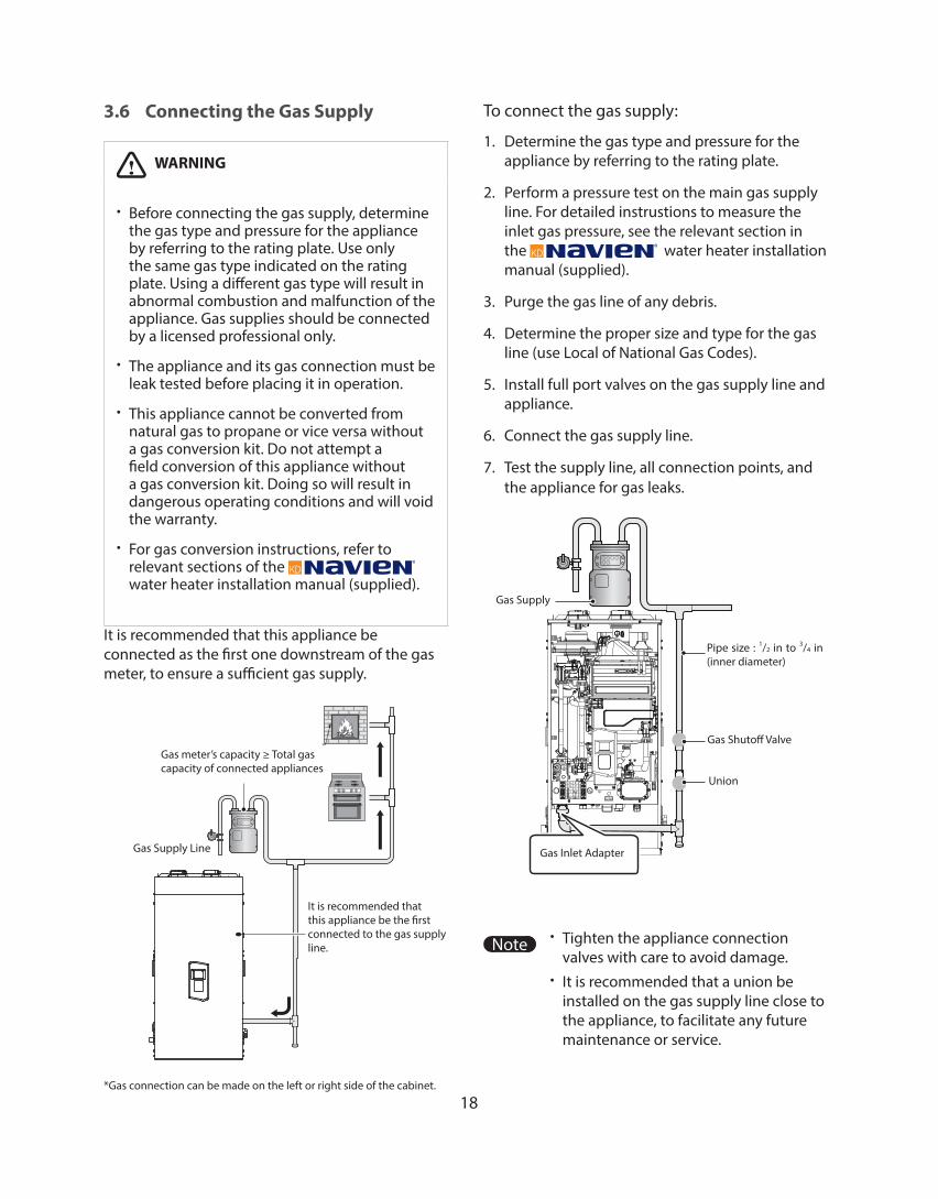
3.6 Connecting the Gas Supply
WARNING
● Before connecting the gas supply, determine the gas type and pressure for the appliance by referring to the rating plate. Use only the same gas type indicated on the rating plate. Using a different gas type will result in abnormal combustion and malfunction of the appliance. Gas supplies should be connected by a licensed professional only.
● The appliance and its gas connection must be leak tested before placing it in operation.
● This appliance cannot be converted from natural gas to propane or vice versa without a gas conversion kit. Do not attempt a field conversion of this appliance without a gas conversion kit. Doing so will result in dangerous operating conditions and will void the warranty.
● For gas conversion instructions, refer to relevant sections of the water heater installation manual (supplied).
It is recommended that this appliance be connected as the first one downstream of the gas meter, to ensure a sufficient gas supply.
It is recommended that this appliance be the first connected to the gas supply line.
Gas Supply Line
Gas meter’s capacity ≥ Total gas capacity of connected appliances
*Gas connection can be made on the left or right side of the cabinet.
To connect the gas supply:
1. Determine the gas type and pressure for the appliance by referring to the rating plate.
2. Perform a pressure test on the main gas supply line. For detailed instrustions to measure the inlet gas pressure, see the relevant section in the water heater installation manual (supplied).
3. Purge the gas line of any debris.
4. Determine the proper size and type for the gas line (use Local of National Gas Codes).
5. Install full port valves on the gas supply line and appliance.
6. Connect the gas supply line.
7. Test the supply line, all connection points, and the appliance for gas leaks.
Union
Gas Shutoff Valve
Gas Supply
Gas Inlet Adapter
Pipe size : 1/2 in to 3/4 in (inner diameter)
18
Note ● Tighten the appliance connection
valves with care to avoid damage. ● It is recommended that a union be
installed on the gas supply line close to the appliance, to facilitate any future maintenance or service.
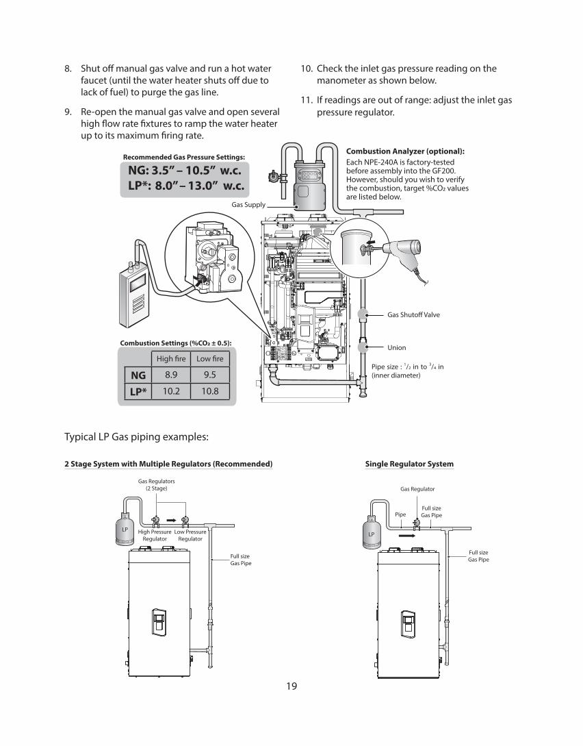
Single Regulator System
19
Gas Regulators (2 Stage)
Full size Gas Pipe
LP High Pressure Regulator
Low Pressure Regulator
Typical LP Gas piping examples:
2 Stage System with Multiple Regulators (Recommended)
8. Shut off manual gas valve and run a hot water faucet (until the water heater shuts off due to lack of fuel) to purge the gas line.
9. Re-open the manual gas valve and open several high flow rate fixtures to ramp the water heater up to its maximum firing rate.
10. Check the inlet gas pressure reading on the manometer as shown below.
11. If readings are out of range: adjust the inlet gas pressure regulator.
Pipe size : 1/2 in to 3/4 in (inner diameter)
Gas Shutoff Valve
Union
Gas Supply
Recommended Gas Pressure Settings:
NG: 3.5” – 10.5” w.c.LP*: 8.0” – 13.0” w.c.
Combustion Settings (%CO2 ± 0.5):
High fire Low fire
NG 8.9 9.5
LP* 10.2 10.8
Combustion Analyzer (optional):Each NPE-240A is factory-tested before assembly into the GF200. However, should you wish to verify the combustion, target %CO2 values are listed below.
Gas Regulator
LP
Full size Gas Pipe
Full size Gas Pipe Pipe

20
8. In the Parameter menu, use the Up (+) or Down (-) buttons to proceed to Parameter 10 (‘P.10’), and then press the ‘Info’ button to enter the ‘Heating MAX set point’ mode (default: 180°F).
9. Use the Up (+) or Down (-) buttons to set this maximum heating set point to 149°F, and then press the ‘Info’ button to confirm the value.
10. Press the Reset button once to return to the Parameter menu, and proceed as above to Parameter 7 (‘P.07’), and then press the ‘Info’ button to enter the ‘Outdoor low temperature value’ mode (default: 14°F).
11. Use the Up (+) or Down (-) buttons to set this low temperature value to 36°F, and then press the ‘Info’ button to confirm the value.
12. Press the ‘Reset’ button 3 times to exit back to the main menu.
13. Remove the jumper and/or return the Control-ler's connections to their original positions.
Once this adjustment is made, standard vent pipe materials may be used throughout. The following table shows the parameters of the default heating profile, with and without high-temperature venting. Note the set point in stages 8-10, as well as the reduced heating output.
3.7 Venting the Appliance
For detailed instructions on venting the appliance, see the relevant section in the
water heater installation manual (supplied).
CAUTION
● This appliance uses temperature settings above 150°F (66°C), which could result in exhaust temperatures in excess of 149°F (65°C). As a result, high-temperature vent pipe materials may be required at the exhaust outlet of the appliance as instructed in the
water heater installation manual.
To adjust the water heater settings to limit the maximum space heating set point, follow these steps:
1. Remove the front cover from the appliance and ensure the main power switch is OFF.
2. Disconnect the H₂Air power supply connector (Connector 'E'; top right; 2-position) from the GF200 Controller (#85566). Apply the jumper (supplied in Kit Box) to this connector.
3. If the jumper is unavailable, the same effect can be achieved by disconnecting the GF200 Controller's power supply (Connector 'A'; top left; 2-position).
4. Ensure the appliance is connected to mains power and flip the main power switch ON.
5. Using the soft-touch button (k
) on the Front Panel, turn the water heater OFF.
6. Enter the ‘R&D information menu’ by pressing, in quick succession:• the Up (+) button three (3) times• the Down (-) button three (3) times• the Up (+) button four (4) more times
7. In the ‘R&D information menu’, use the Up (+) or Down (-) buttons to move to ‘2.PAR’, then press the ‘Info’ button (middle left) to enter the ‘Parameter’ menu. If necessary: to return to the previous menu, press the ‘Reset’ button once.
Note Allowable venting materials are at the discretion of the inspector. This non-permanent method for reducing exhaust temperatures may not satisfy all local authorities.

3.8 Connecting the Electrical
WARNING
Improperly connecting the power supply can result in electrical shock and electrocution. Follow all applicable electrical codes of the local authority having jurisdiction. In the absence of such requirements, follow the latest edition of the National Electrical Code (NFPA 70) in the USA or the latest edition of CSA C22.1 Canadian Electrical Code Part 1 in Canada. Connecting the power supply should be performed only by a licensed professional.
When connecting the power supply, follow these guidelines:
● Do not connect the electric supply until all plumbing and gas piping is complete and the appliance has been filled with water.
● Do not connect the appliance to a 220-240 V AC power supply. Doing so will damage the appliance and void the warranty.
● This appliance must be wired directly. It is recommended that a power switch be installed between the breaker and the appliance to facilitate end-user maintenance and servicing.
● Connect the appliance to a 110-120 V AC circuit at 60 Hz, with a minimum circuit ampacity (MCA) of 15 A, and a maximum circuit breaker size of 20 A, as per the rating plate.
● Ensure that the appliance is electrically grounded via the GND circuit on the barrier strip. Do not attach the ground wire to either the gas or the water piping as plastic pipe or dielectric unions may prevent proper grounding.
● If there is a power failure in cold weather areas, the freeze prevention system in the appliance will not operate and may result in freezing of the heat exchanger and or coil. In cold weather areas where power failures are common, you must completely drain the appliance to prevent damage if the power will be off for any extended period of time. A battery back-up (available at most computer retailers) may be used to supply hot water during periods of power outages. Damage caused by freezing is not covered under warranty.
21
3.8.1 Connecting the power supply wiring
A 7/8" (0.875 in.) panel hole is provided on each side of the cabinet for mechanical strain relief (see "Line Voltage" in the following diagram):
The Field Wiring Panel is located behind a galvanized steel safety plate, held in place by a single 1/4" hex screw. Two grommet-lined holes are provided at the base of this panel for routing field wiring.
19.5in 495mm
16.4
in41
6mm
10.9in 276mm
10.5in 266mm
6.3i
n16
0mm
4.7i
n12
0mm
36.5
in92
7mm
19.6in 498mm17.7in 450mm
37.2
in94
4mm
37.9in 963mm
9.3in 236mm
12.9in 328mm
3.9i
n10
0mm
6.4i
n16
2mm
6.8in 173mm
38.0
in96
4mm
Inlet Conn. (3/4" Socket)
Outlet Conn. (3/4" Socket)
Line Voltage
Field Wiring
Gas Conn.
Condensate Conn.
Service switch (field-supplied)
120V /1P/60HZ15 A FUSEDPOWER SUPPLY
When connecting the power supply wires to the Field Wiring Panel, use connections 10, 11, and 12 for Ground, Neutral, and Line, respectively:

3.8.2 Connecting the low-voltage wiring
All low-voltage wiring is intended to pass through the 1” slit grommet below the gas line panel hole on either side of the cabinet (swap grommet for caplug accordingly):
Flow switch:
The two wires in the flow switch cable must be connected to the labeled terminals in the barrier strip. Failure to install and connect the flow switch correctly could result in high-temperature water being sent to the thermostatic mixing valve, increasing the potential for injurious burns.
Thermostat:
The GF200’s Green Furnace Technology modulates automatically through 10 heating stages to match its output to the load. As such, it accepts only one ‘W’ input. Connect your thermostat wires accordingly.
The W, G, Y1, and Y2 inputs, if used, must be wired directly from the thermostat (or in such a way that is electrically indistinguishable).
Freeze protection:
The GF200 protects its heating coil from freezing by only allowing the A/C system's condenser (outdoor unit) to run when the circulating blower is within its normal operating envelope (see Appendix 4.1). As such, when wiring the cooling system, it is imperative that the return leg of the control wire from the outdoor unit be wired to the ‘YC’ terminal on the barrier strip. Failure to do so correctly may void the warranty and could cause significant property damage.
1 FLOW SWITCH
Connect the two leads from the external flow switch here (one per terminal). Note: The ‘hot’ lead only becomes energized (from the H2Air board) when Central Heating mode (W) is active.
COMPRESSOR COMMON: Connect return leg from Outdoor A/C Unit control
YC 7
2 FLOW SWITCH
COOLING (2nd Stage): Connect second stage cooling wire from thermostat here (see Appendix 4.1 for CFM table)
Y2 8
3
THER
MO
STAT
(DRY
CO
NTA
CTS
) GVENTILATION: Connect ventilation / circulation wire from thermostat here.
COOLING (1st Stage): Connect first stage cooling wire from thermostat here (see Appendix 4.1)
Y1 9
4 WHEAT: Connect heating wire from ther-mostat here.
GROUND: Connect earth ground wire here.
GROUND 10
5 R (24 VAC)
24 V AC OUTPUT: Connect power input wire to thermostat here.
NEUTRAL: Connect the neutral wire for the power supply here
L2 (NEUTRAL)
11
6 COMMCOMMON: Connect common wire from thermostat here.
LINE: Connect the line voltage wire for the power supply here
L1 (120 VAC)
12
22

23
3.9 Configuring the appliance
These last few steps will finalize the installation, and set-up the GF200 to provide comfortable space heating, cooling, and DHW for years to come.
3.9.1 Selecting a Pre-heat Recirculation Mode
One may choose from two pre-heating modes: ComfortFlow Recirculation mode or Navien Intelligent Pre-heating mode. To select a recirculation mode, you must set the DIP switches on the Front Panel (see section 3.9.2 for details).
When an optional recirculation mode is activated, energy consumption may increase because the water heater operates to maintain the water temperature within the circulation loop.
Pre-heat recirculation has three performance advantages:
• Elimination of any minimum flow rate requirement.
• Elimination of any hot/cold/hot stacking — the “cold water sandwich“ effect.
• Quicker hot water delivery to fixtures, which results in less water wasted.
At all times, the 2-way valve at the base of the buffer tank must remain in the EXT position, as it is factory-set (shown below). Otherwise, the GF 200 will be unable to provide any space heating.
Primary Heat Exchanger
Secondary Heat Exchanger
FlowSensor
DomesticWater
Supply
Bypass
PumpCheckValve
WaterAdjustment
Valve
BufferTank
DHWSupply
Space Heating Fan Coil
3-way Valve
3.9.2 Setting the DIP Switches
This appliance has two installer-serviceable DIP switch blocks: 12 on the Front Panel, and 4 on the Interface Board, mounted on the frame of the PCB.
Interface Board DIP Switches (H₂Air)
The four DIP switches on the interface Board con-figure the settings governing central heating oper-ation. These configurations are set at the factory (OFF | ON | OFF | OFF) and should not be changed.
However, should absolute DHW priority be desired, such that any DHW demand disables all central heating activity for the duration of the demand, DIP switch #2 may be set to OFF.
Front Panel DIP Switches
The two sets of DIP switches on the front panel configure the recirculation, display, well pump, storage tank & solar system, temperature lock, lime alarm, high altitude, cascade venting and gas type settings. Some of these configurations are set at the factory and should not be changed. The following tables describe the functions of the DIP switches and their settings:
The following diagram shows the recirculation flow for pre-heating (through the 'Bypass'):

10-switch Panel:
Switch Function Setting Remark
1-3Pre-heat Recirculation Mode
No Recirculation (factory default) 1-OFF; 2-OFF; 3-OFF * Intelligent Preheating: Learns the user's hot water usage patterns and starts preheating prior to an anticipated draw. ● Freeze protection is still
available with preheating OFF.
**Temperature Lock: When enabled, displays "LOCK" when an attempt is made to adjust the DHW temperature set point.
***Lime Alarm: Displays a "760" error when the set time period has been reached to indicate a flush or service is necessary.
****High Altitude: Above 2,000 ft (610 m), the appliance will de-rate by 4% for each 1,000 ft (305 m) of altitude gain.
ComfortFlow Recirculation (factory default for S/N pre-97974) 1-ON; 2-OFF; 3-OFF
Intelligent Preheating* 1-ON; 2-ON; 3-OFF
4 Display Temperature Unit
Celsius 4-ON
Fahrenheit 4-OFF
5 Well PumpWell Pump Operation 5-ON
Do Not Use Well Pump 5-OFF
6 DHW Storage Tank/Solar System
Storage Tank/Solar System Operation 6-ON
Do Not Use Storage Tank/Solar System 6-OFF
7 Temperature Lock**
Temperature Lock Enabled 7-ON
Temperature Lock Disabled 7-OFF
8 Lime Alarm***12 Months Alert 8-ON
Lime Alarm Disabled 8-OFF
9 & 10 High Altitude ****
0–1,999 ft (0–609 m) 9-OFF, 10-OFF
2,000–5,399 ft (610–1,645 m) 9-ON, 10-OFF
5,400–7,699 ft (1,646–2,346 m) 9-OFF, 10-ON
7,700–10,100 ft (2,347–3,078 m) 9-ON, 10-ON
Note This appliance may be installed at elevations up to 10,100 ft (3,078 m) for use with Natural Gas and 4,500 ft (1,370 m) for use with Propane. To use the appliance at a specific altitude, the DIP switches should be set as described above.
**Temperature Lock only applies to units bearing a water heater serial number later than [ XXXXX16706XXXXX ]. Earlier models combine DIP switches 7 & 8 to allow for a Lime Alarm of 6, 12, 24 months (ON | OFF; OFF | ON; and ON | ON, respectively), or no alarm at all (OFF | OFF).
2-switch Panel:
Switch Function Setting
1 Cascade Vent (N/A to GF200)Common Vent 1-OFF
Individual Vent 1-ON
2 Gas TypeNatural Gas 2-OFF
Propane Gas 2-ON
24

3.9.3 Setting air flow rates
The GF200 is designed to operate with second-stage (Y2) cooling air flow rates between 700 and 1450 CFM. First-stage (Y1) cooling and circulation (G) air flow rates are set to 70% and 50% of second-stage (Y2) rates, respectively. Depending on evaporator capacity, climatic conditions, and owner preference, one may choose any Y2 value between 700 and 1450, in increments of 50 CFM (see table below).
The following rates apply at all operating points within the specified external static pressure range (0 – 0.8 in w.c.):
25
Once a value is selected (by following the steps below), it will remain in solid-state memory. The default setting is the maximum, 1450 CFM (all 4 LEDs illuminated).
1. Remove the front cover from the appliance.
2. Connect the appliance to mains power and flip the main power switch ON.
3. Using the soft-touch button on the Front Panel, turn the water heater OFF.
4. Remove the protective cover from the controller enclosure (4 Phillips head screws).
5. Locate the push-button in the lower left corner of the controller enclosure (see figure below).
6. Locate the 4 numbered LEDs (circled and labeled below) that will indicate the air flow programming setting.
7. Using the table above, determine which LED combination corresponds to the desired CFM rate. For single-stage applications, one may use Y1 or Y2 (adjust wiring accordingly).
8. Press and hold the Push Button for 3 seconds (LED #4 will stop flashing for these seconds), then release it.
LED #1LED #2
LED #3 LED #4PUSH BUTTON
Note Ignore all other LEDs when in Programming Mode.
This activates Programming Mode, in which the numbered LEDs will identify which setting is currently programmed.
9. Each subsequent press increases the second-stage (Y2) cooling air flow rate by 50 CFM, as per the table above. Once all 4 LEDs are lit (Y2 = 1450 CFM), the next press will loop back to the beginning (Y2 = 700 CFM). For example, to set Y2 = 1000 CFM, starting from the default state of all 4 LED being lit, one would simply press the button 7 times.
10. Confirm the setting using the 4 LEDs (shown in the figure below and the table above).
11. Once the desired setting has been selected, wait 10 seconds. The LEDs will return to their former states, and the values will be saved as the controller exits Programming Mode.
12. Should the controller exit Programming Mode prematurely, simply repeat Steps 7 – 10. If Step 7 fails to engage Programming Mode, power cycle the controller and try again.

26
3.10.2 Setting the DHW temperature:
The Front Panel control interface allows the user to adjust the DHW set point directly. As such, assuming a Thermostatic Mixing Valve (TMV) has been installed on the DHW outlet of the appliance (as directed in this installation manual), it is recommended that the DHW set point be set between 130°F – 140°F to optimize space heating performance at high loads during DHW draws.
If a TMV has not been installed, it is recommended that the user request one be installed, as it provides important protection against scalding, even when the DHW set point is relatively low (e.g. 120°F).
To adjust the DHW set point (see Section 3 of the Operation Manual (supplied):
• From the Normal Operation menu (system on, in standby mode: no faucets or pumps running), simply press the Up (+) or Down (-) buttons to adjust set point as desired. One must press-and-hold the buttons for ~2 seconds when adjusting the temperature between 120°F and 140°F (in 5°F increments only).
• When finished, simply avoid pressing any buttons until the display stops flashing, and the set value will be saved.
Any time a DHW load is detected, the DHW set point will become the active supply temperature for the duration of the demand, even during central heating (so long as the flow switch is installed and operating).

4. Appendices4.1 Blower Performance
27
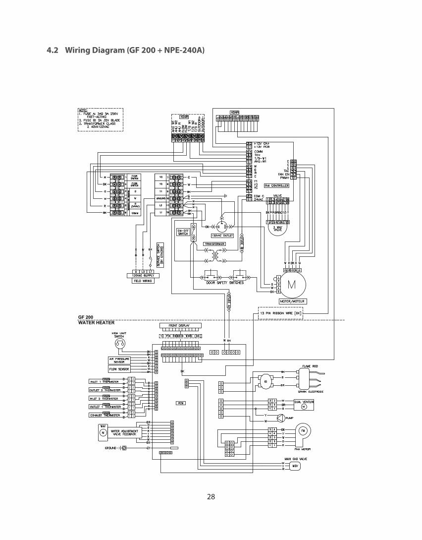
4.2 Wiring Diagram (GF 200 + NPE-240A)
28
GF 200WATER HEATER
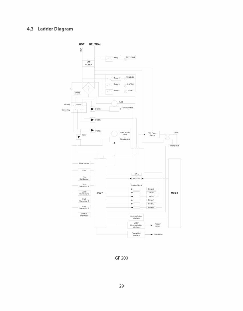
4.3 Ladder Diagram
HOT NEUTRAL
VENTURI
Relay 1
Relay 2
Relay 3
Relay 4
IGNITER
PUMP
Speed Control
Primary
MCU 1 MCU 2
DC24V
Flow Sensor
APS
DC12V
FAN
Water Adjust Valve
Flow Control
DC15V
UARTCommunication
Interface
Ready LinkInterface Ready Link
FanHall Sensor
OutletThermistor 2
InletThermistor 1
InletThermistor 2
OutletThermistor 1
ExhaustThermistor
EXT_PUMP
FRONT PANEL
CommunicationInterface
Relay 3
Relay 2
Relay 4
Driving Circuit
MGV1
MGV2
Relay 1
FSA Power Switch
Flame Rod
200V
PWM
EMIFILTER
DC5V
H.T.L
WD-PSS
SMPSPrimary
Secondary
3.15
A
GF 200
29

4.4 Component Diagrams and Parts Lists
4.4.1 Case Assembly
3
43
44
37
10
11
14
13
36
30
26
31
33 34
32 35
27
464749
45
42
4041
28
17
2425
12
18
20 2122
16
23
6
19
39
29
38
1
9
4
2
7
5
15
8
24
51
50
52
48
53
30

# Description Part # # Description Part #
1 Intake Air Duct Assembly 30008662B 29 Bottom Door Rail TBD
2 Intake Air Filter 20007667A 30 Blower Shelf TBD
3 Case 20019078C 31 Spine TBD
4 Air Pressure Sensor 30010346A 32 Hopper, Front TBD
5 PCB 30011969A 33 Hopper, Left TBD
6 Power Switch 30009482A 34 Hopper, Back TBD
7 Front Panel (touch screen) 30008333A 35 Hopper, Right TBD
8 Case Bracket 20007609A 36 Coil Mount TBD
9 Exhaust Pipe Assembly 30008673A 37 Back TBD
10 Top Panel TBD38
Top Door Rail Right TBD
11 Left Side TBD Top Door Rail Left TBD
12 Electrical Cover TBD 39 Side Door Rail TBD
13 Logo 81613 40 Receptacle, 120V 84423
14 Display Bezel 85565 41 Handle 81622
15 Front Cover TBD 42 Door Safety Switch 83208
16 Screen Mount TBD 43 Right Side TBD
17 Screen Support Bracket TBD 44 Side Door TBD
18 Electrical Panel TBD 45 Grommet, Diaphragm 0.5" 84214
19 Door Latch TBD 46 Cap, 2" 85564
20 Grommet, Ring 85205 47 Cap, 1" 85563
21 Barrier Strip 85556 48 Cap, 0.75" 85562
22 Air Handler Controller 85566 49 Plug, 0.875" 84095
23 Transformer 83190 50 Grommet, 1"ID 83923
24 Grommet, 0.75" ID 85559 51 Circulating Blower 85546
25 Grommet, 1.25"OD Slit 85254 52 H2Air Controller 85535
26 Bottom TBD 53 Fuse Holder 84192
27 Blower Mount Bracket TBD
28 Door Latch Keeper TBD
31

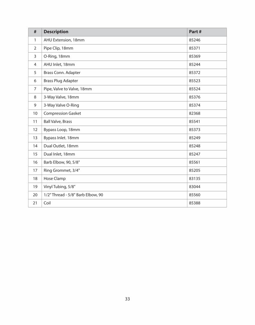
4.4.2 Waterway Assembly
1
2
3
4
5
6
78
1011
1213
14
15
10
1618 17
1920 18
21
20
3
9
32
33
# Description Part #
1 AHU Extension, 18mm 85246
2 Pipe Clip, 18mm 85371
3 O-Ring, 18mm 85369
4 AHU Inlet, 18mm 85244
5 Brass Conn. Adapter 85372
6 Brass Plug Adapter 85523
7 Pipe, Valve to Valve, 18mm 85524
8 3-Way Valve, 18mm 85376
9 3-Way Valve O-Ring 85374
10 Compression Gasket 82368
11 Ball Valve, Brass 85541
12 Bypass Loop, 18mm 85373
13 Bypass Inlet. 18mm 85249
14 Dual Outlet, 18mm 85248
15 Dual Inlet, 18mm 85247
16 Barb Elbow, 90, 5/8" 85561
17 Ring Grommet, 3/4" 85205
18 Hose Clamp 83135
19 Vinyl Tubing, 5/8" 83044
20 1/2" Thread - 5/8" Barb Elbow, 90 85560
21 Coil 85388

4.5 Installation Checklist
After installing the appliance, review the following checklist. You should be able to answer “Yes” to all of the items in the checklist. If not, review the appropriate sections to complete the installation. If you have additional questions or need assistance with installation, contact Technical Support at 1-800-688-2575.
The following check list is intended to supplement those found in the water heater manual, and focuses on installation details specific to the overall appliance.
34
Venting the Water Heater Yes No
Have you vented the water heater using the correct temperature rated materials for the maximum space heating setpoint?
Connecting the Power Supply Yes No
Is the supplied voltage 110-120 V AC?
Have you installed a power switch to facilitate end-user maintenance?
Have you checked the polarity of the electrical connection?
Setting the DIP Switches Yes No
Have you verified the positions of all DIP switches on the interface board?
Have you verified the positions of all DIP switches on the front panel?
Operating the Appliance Yes No
Have you given both Installation Manuals and the water heater Operations Manual to the owner for future reference?
Have you shown the owner how to clean/replace the return air filter?
Water Heater Checklist Yes No
Have you completed the Installation Checklist in the Water Heater Installation Manual?
Ducting the Appliance Yes No
Have you set the appropriate cooling flow rate for the installation?
Have you installed a return air filtration system?
Plumbing the Appliance Yes No
Have you installed a thermostatic mixing valve on the appliance hot water outlet?
35
4.6 Troubleshooting
E.438 – Abnormal circulation pump
о Error description:
◊ Incongruity between Pump activation signal and Flow Sensor reading.
о Potential causes:
◊ Air-lock
• During commissioning, the first Central Heat call may introduce air into the pump, which can overwhelm the impeller and induce air-lock.
◊ Faulty Flow Sensor or Pump
• It is possible that the pump is failing to generate any flow, or that the sensor is failing to read it.
о Troubleshooting:
◊ If air-lock is suspected (when error appears during Central Heating):
• Ensure that the air eliminator on top of the pump housing is open.
• Flood the pump chamber by opening the valve between it and the Buffer Tank (set it to 'INT')
• Press Reset button (bottom left) to clear the error code and resume Central Heating (if call still active).
• Once the pump resumes operation, air should begin escaping from the eliminator.
• Slowly close the valve by the valve by setting it back to 'EXT'. Air should continue to escape.
• If E.438 re-appears, repeat this procedure. If the air-lock does not clear after 3 attempts, check inlet water supply (and pressure), and attempt a Central Heat call with a simultaneous DHW draw (~ 2 GPM).
◊ Otherwise:
◊ Check Flow Sensor:
• Get back to Stand-by mode (i.e. stop heating (‘W’) call).
• Apply a DHW draw and observe the flow sensor’s output.
• Press Info button (middle left), then [ – ] to see the current flow rate (GPM).
• If readout corresponds to expected flow rate value (based on visible water flow at the fixture), we can eliminate the Flow Sensor as the root of the error.
◊ Check that brass isolation valve is open
• Make sure the black plastic handle is parallel to the valve body and piping
◊ Perform a Pump Test
• From Stand-by, press and hold Diagnostics button (top left) for 5 seconds to enter Test mode
• Press Info button to enter Test menu, and use [ + ] and [ – ] buttons to scroll to “Pump”.
• Press Info button to start the test (5-10 seconds on/off cycles for 1 minute)
• Observe display readout – it should cycle between “On” / “Off” and “_ . _” GPM
If these steps fail to resolve the error, contact NTI Technical Support for further assistance.
36
Symptom: Fan (circulating blower) not running
о Potential causes:
◊ High-voltage (120 V) supply issue
• Door switches could be breaking contact.
◊ Signal issue
• Controller could have found a problem during boot-up checks.
• Signal could not be reaching the circulating blower (possibly due to equipment failure).
о Troubleshooting:
◊ Eliminate all other calls (remove wires from W, G, Y1, and Y2 terminals)and remove the front cover from the GF200 Controller (Part No. 85566), revealing the circuit board. Ensure the GF200 is at idle before proceeding.
◊ Apply a jumper between R and G while monitoring the exposed circuit board of the controller.
• Does the 'G' status LED ( [LED4], below connector 'C') light up when the jumper is connected?
• If YES, check that the FAN Status LED ( [LED10], bottom right) is ON.
• If YES, check for 120 V AC at the fan (5-position connector). Black wire should be 'hot' relative to ground (green). BE SURE to make the door switch after removing the door to access the fan.
• If YES, check for PWM signal at the fan (16-position connector). Look for 1 – 5 V DC between black and green (during an active fan demand).
• If YES, consider replacing Motor Control Module
• If NO, repeat check for PWM signal at the Controller (connector 'F'; 6-position)
• If YES, replace Fan Control Harness (contact Technical Support)
• If NO, consider replacing Controller (p/n: 85566)
• If NO, check for 120 V AC at all door switch terminals (also check that switches are making).
• If 120 V AC is not present at any door switch terminal, trace wire back to panel, checking for voltage at any connection point.
• If NO, check 3-way valve (rainbow) harness (connected to left side of Controller) for faults.
• If any wires with intact crimp terminals are found to be loose, reinsert them (audible click).
• If any wires with bare ends are loose, the harness must be replaced.
• To check communication to the 3-way valve:
• Power-cycle the Controller (disconnect connector 'A'; top left; 2 wires – blue and black)
• Plug in connector 'A' while keeping a hand on the 3-way valve motor's white plastic body.
• Feel for the motor's steady hum (approx. 3 sec.), pause, and return hum.
If these steps fail to resolve the error, contact NTI Technical Support for further assistance.

37

38
NOTES

39
NOTES

NTI Boilers1-800-688-2575 www.NTIBoilers.com30 Stonegate Drive, Saint John, NB, E2H 0A4
Installation ManualGF 200
Getting Service
If your appliance requires service, you have several options for getting service: ● Contact Technical Support at 1-800-688-2575 or on the website: www.NTIBoilers.com. ● For warranty service, always contact Technical Support first. ● Contact the technician or professional who installed your water heater. ● Contact a licensed professional for the affected system (for example, a plumber or electrician).
When you contact Technical Support, please have the following information at hand: ● Model number ● Serial number ● Date purchased ● Installation location and type ● Error code, if any appears on the front panel display
Version: 2.0 (April 2018)