Embed Size (px)
Citation preview
D.1www.lmt-tools.com
Gew
inde
n Th
read
ing
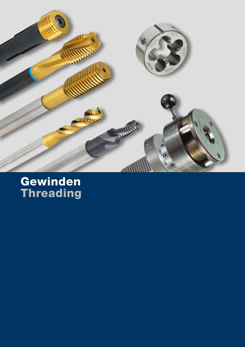
GewindenThreading
D.1www.lmt-tools.com
Inhaltsübersicht Content
D.3 Gewindebohren TappingD.5 Gewindebohrer metrisch Taps metricD.73 Gewindebohrer metrisch-fein Taps metric fineD.109 Gewindebohrer UNC/UNF Taps UNC/UNFD.139 Gewindebohrer G, UNJF/MJ, NPT/NPTF, BSW, RP Taps G, UNJF/MJ, NPT/NPTF, BSW, RP
D.165 Gewindeformen Thread formingD.165 Gewindeformer M, MF, UNC, UNF, G Forming Taps M, MF, UNC, UNF, G
D.191 Gewindefräsen Thread millingD.194 Vollhartmetall-Gewindefräser Solid carbide thread milling cuttersD.197 Gewindefräser mit Wendeplatten Thread milling cutters with indexable inserts
D.201 Schneideisen DiesD.201 Schneideisen M, MF, UNC, UNF, G, W, Pg, NPT Dies M, MF, UNC, UNF, G, W, Pg, NPT
D.217 Gewinderollen Thread rollingD.225 Axial-Gewinde-Rollköpfe Axial thread rolling headsD.239 Radial-Gewinde-Rollköpfe Radial type thread rolling headsD.253 Tangential-Gewinde-Rollköpfe Tangential thread rolling heads
Gew
inde
n Th
read
ing
D.2 www.lmt-tools.com
GewindebohrenTapping

D.3www.lmt-tools.com
Gew
inde
n Th
read
ing
Gewindebohren Tapping
D.5 Gewindebohrer metrisch Taps metric
D.73 Gewindebohrer metrisch-fein Taps metric fine
D.109 Gewindebohrer UNC/UNF Taps UNC/UNF
D.139 Gewindebohrer G, UNJF/MJ, NPT/NPTF, BSW, RP Taps G, UNJF/MJ, NPT/NPTF, BSW, RP
D.4 www.lmt-tools.com
Gewindebohrer metrischTaps metric
D.5www.lmt-tools.com
Gew
inde
n Th
read
ing
Gewindebohrer metrisch Taps metric
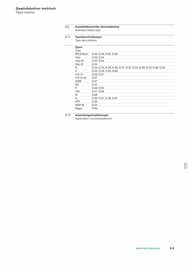
D.6 Auswahlübersichten Gewindebohrer Selection tables taps
D.14 Typenbeschreibungen Type descriptions
Typen Type
PM-Edition D.46, D.49, D.62, D.66Vdry D.50, D.64Vdry-M D.50, D.64Vdry-S D.64N D.23, D.25, D.28, D.30, D.31, D.32, D.33, D.39, D.53, D.56, D.63V D.26, D.28, D.45, D.60V-R 15 D.28, D.57V-R 15-IK D.57WZM D.27VN D.52H D.48, D.65TiNi D.51, D.68Ni D.69G D.36, D.37, D.38, D.67HPT D.50VHM-IK D.22Magic D.63
D.70 Anwendungsempfehlungen Application recommendations
D.6 www.lmt-tools.com
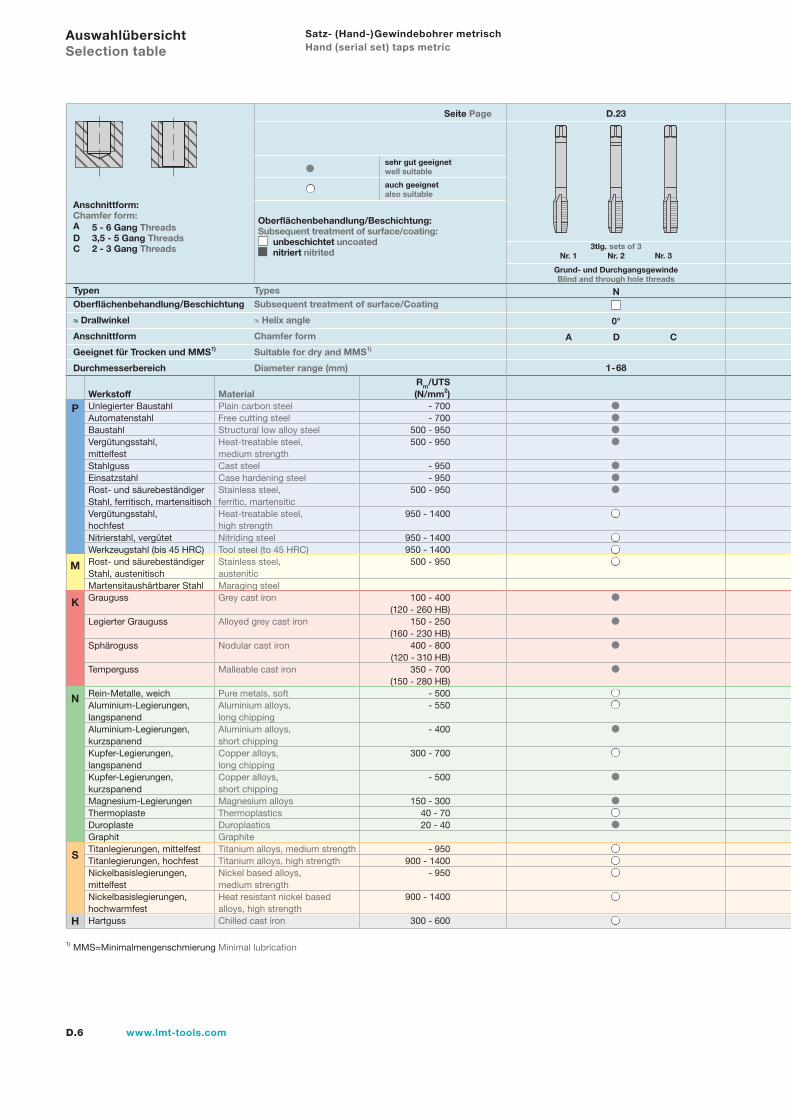
Satz- (Hand-)Gewindebohrer metrisch Hand (serial set) taps metric
Typen TypesOberflächenbehandlung/Beschichtung Subsequent treatment of surface/Coating
≈ Drallwinkel ≈ Helix angle
Anschnittform Chamfer form
Geeignet für Trocken und MMS1) Suitable for dry and MMS1)
Durchmesserbereich Diameter range (mm)
Anschnittform:Chamfer form:A 5 - 6 Gang ThreadsD 3,5 - 5 Gang ThreadsC 2 - 3 Gang Threads
Oberflächenbehandlung/Beschichtung:Subsequent treatment of surface/coating:
unbeschichtet uncoated nitriert nitrited
sehr gut geeignetwell suitable
auch geeignetalso suitable
Seite Page
Grund- und DurchgangsgewindeBlind and through hole threads
1) MMS=Minimalmengenschmierung Minimal lubrication
D.23
3tlg. sets of 3 Nr. 1 Nr. 2 Nr. 3
0°
A D C
N
1-68
Auswahlübersicht Selection table
P
M
K
N
S
H
Rm/UTSWerkstoff Material (N/mm2)Unlegierter Baustahl Plain carbon steel - 700Automatenstahl Free cutting steel - 700Baustahl Structural low alloy steel 500 - 950Vergütungsstahl, Heat-treatable steel, 500 - 950mittelfest medium strengthStahlguss Cast steel - 950Einsatzstahl Case hardening steel - 950Rost- und säurebeständiger Stainless steel, 500 - 950Stahl, ferritisch, martensitisch ferritic, martensiticVergütungsstahl, Heat-treatable steel, 950 - 1400hochfest high strengthNitrierstahl, vergütet Nitriding steel 950 - 1400Werkzeugstahl (bis 45 HRC) Tool steel (to 45 HRC) 950 - 1400Rost- und säurebeständiger Stainless steel, 500 - 950Stahl, austenitisch austeniticMartensitaushärtbarer Stahl Maraging steelGrauguss Grey cast iron 100 - 400 (120 - 260 HB)Legierter Grauguss Alloyed grey cast iron 150 - 250 (160 - 230 HB)Sphäroguss Nodular cast iron 400 - 800 (120 - 310 HB)Temperguss Malleable cast iron 350 - 700 (150 - 280 HB)Rein-Metalle, weich Pure metals, soft - 500Aluminium-Legierungen, Aluminium alloys, - 550langspanend long chippingAluminium-Legierungen, Aluminium alloys, - 400kurzspanend short chippingKupfer-Legierungen, Copper alloys, 300 - 700langspanend long chippingKupfer-Legierungen, Copper alloys, - 500kurzspanend short chippingMagnesium-Legierungen Magnesium alloys 150 - 300Thermoplaste Thermoplastics 40 - 70Duroplaste Duroplastics 20 - 40Graphit GraphiteTitanlegierungen, mittelfest Titanium alloys, medium strength - 950Titanlegierungen, hochfest Titanium alloys, high strength 900 - 1400Nickelbasislegierungen, Nickel based alloys, - 950mittelfest medium strengthNickelbasislegierungen, Heat resistant nickel based 900 - 1400hochwarmfest alloys, high strengthHartguss Chilled cast iron 300 - 600
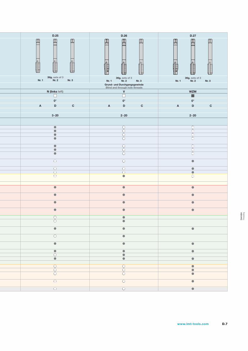
D.7www.lmt-tools.com
N (links left)
Grund- und DurchgangsgewindeBlind and through hole threads
0°
A D C
3-20
D.25
3tlg. sets of 3 Nr. 1 Nr. 2 Nr. 3
0°
A D C
WZM
2-20
3tlg. sets of 3 Nr. 1 Nr. 2 Nr. 3
D.27
0°
A D C
V
2-20
D.26
3tlg. sets of 3 Nr. 1 Nr. 2 Nr. 3
Gew
inde
n Th
read
ing
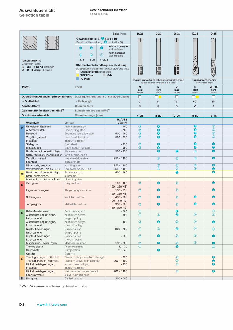
D.8 www.lmt-tools.com
Gewindebohrer metrisch Taps metric
Typen Types
Oberflächenbehandlung/Beschichtung Subsequent treatment of surface/coating
Drallwinkel Helix angle
Anschnittform Chamfer form
Geeignet für Trocken und MMS1) Suitable for dry and MMS1)
Durchmesserbereich Diameter range (mm)
Anschnittform:Chamfer form:B 3,5 - 5 Gang ThreadsC 2 - 3 Gang Threads
0°
C
Nkurz short
1-68
Seite Page D.28
Grund- und/oder DurchgangsgewindebohrerBlind and/or through hole taps
GrundgewindebohrerBlind hole taps
1) MMS=Minimalmengenschmierung Minimal lubrication
Rm/UTSWerkstoff Material (N/mm2)Unlegierter Baustahl Plain carbon steel - 700Automatenstahl Free cutting steel - 700Baustahl Structural low alloy steel 500 - 950Vergütungsstahl, Heat-treatable steel, 500 - 950mittelfest medium strengthStahlguss Cast steel - 950Einsatzstahl Case hardening steel - 950Rost- und säurebeständiger Stainless steel, 500 - 950Stahl, ferritisch, martensitisch ferritic, martensiticVergütungsstahl, Heat-treatable steel, 950 - 1400hochfest high strengthNitrierstahl, vergütet Nitriding steel 950 - 1400Werkzeugstahl (bis 45 HRC) Tool steel (to 45 HRC) 950 - 1400Rost- und säurebeständiger Stainless steel, 500 - 950Stahl, austenitisch austeniticMartensitaushärtbarer Stahl Maraging steelGrauguss Grey cast iron 100 - 400 (120 - 260 HB)Legierter Grauguss Alloyed grey cast iron 150 - 250 (160 - 230 HB)Sphäroguss Nodular cast iron 400 - 800 (120 - 310 HB)Temperguss Malleable cast iron 350 - 700 (150 - 280 HB)Rein-Metalle, weich Pure metals, soft - 500Aluminium-Legierungen, Aluminium alloys, - 550langspanend long chippingAluminium-Legierungen, Aluminium alloys, - 400kurzspanend short chippingKupfer-Legierungen, Copper alloys, 300 - 700langspanend long chippingKupfer-Legierungen, Copper alloys, - 500kurzspanend short chippingMagnesium-Legierungen Magnesium alloys 150 - 300Thermoplaste Thermoplastics 40 - 70Duroplaste Duroplastics 20 - 40Graphit GraphiteTitanlegierungen, mittelfest Titanium alloys, medium strength - 950Titanlegierungen, hochfest Titanium alloys, high strength 900 - 1400Nickelbasislegierungen, Nickel based alloys, - 950mittelfest medium strengthNickelbasislegierungen, Heat resistant nickel based 900 - 1400hochwarmfest alloys, high strengthHartguss Chilled cast iron 300 - 600
Oberflächenbehandlung/Beschichtung:Subsequent treatment of surface/coating: unbeschichtet uncoated
TiCN Plus CrN IQ Plus
Gewindetiefe (z.B. bis 3 x D)Depth of thread (e.g. up to 3 x D)
~ 1-1,5 x D~ 2 x D~ 3 x D
sehr gut geeignetwell suitable
auch geeignetalso suitable
Auswahlübersicht Selection table
P
M
K
N
S
H
40°
C
Nkurz short
3-20
0°
C
Vkurz short
2-20
D.28
0°
B
Nkurz short
2-20
D.30 D.31 D.28
15°
E
VR-15kurz short
3-16
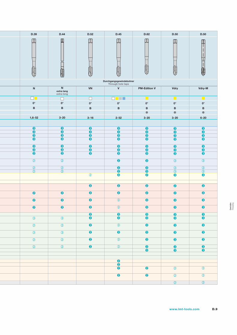
D.9www.lmt-tools.com
0°
B
N
1,6-52
Nextra lang extra long
0°
B
3-20
DurchgangsgewindebohrerThrough hole taps
0°
B
V
2-52
0°
B
VN
3-16
PM-Edition V
D.39 D.44 D.52 D.45 D.62
B
0°
3-20
D.50 D.50
B
0°
3-20
B
0°
6-20
Vdry Vdry-M
Gew
inde
n Th
read
ing
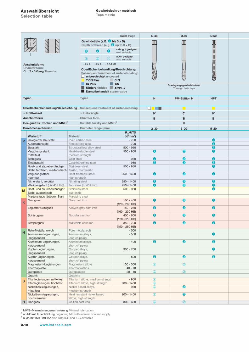
D.10 www.lmt-tools.com
Gewindebohrer metrisch Taps metric
Typen Types
Oberflächenbehandlung/Beschichtung Subsequent treatment of surface/coating
Drallwinkel Helix angle
Anschnittform Chamfer form
Geeignet für Trocken und MMS1) Suitable for dry and MMS1)
Durchmesserbereich Diameter range (mm)
Seite Page
1) MMS=Minimalmengenschmierung Minimal lubrication2) ab M6 mit Innenkühlung beginning M6 with internal coolant supply3) auch mit IKR und IKZ also with ICR and ICC available
Rm/UTSWerkstoff Material (N/mm2)Unlegierter Baustahl Plain carbon steel - 700Automatenstahl Free cutting steel - 700Baustahl Structural low alloy steel 500 - 950Vergütungsstahl, Heat-treatable steel, 500 - 950mittelfest medium strengthStahlguss Cast steel - 950Einsatzstahl Case hardening steel - 950Rost- und säurebeständiger Stainless steel, 500 - 950Stahl, ferritisch, martensitisch ferritic, martensiticVergütungsstahl, Heat-treatable steel, 950 - 1400hochfest high strengthNitrierstahl, vergütet Nitriding steel 950 - 1400Werkzeugstahl (bis 45 HRC) Tool steel (to 45 HRC) 950 - 1400Rost- und säurebeständiger Stainless steel, 500 - 950Stahl, austenitisch austeniticMartensitaushärtbarer Stahl Maraging steelGrauguss Grey cast iron 100 - 400 (120 - 260 HB)Legierter Grauguss Alloyed grey cast iron 150 - 250 (160 - 230 HB)Sphäroguss Nodular cast iron 400 - 800 (120 - 310 HB)Temperguss Malleable cast iron 350 - 700 (150 - 280 HB)Rein-Metalle, weich Pure metals, soft - 500Aluminium-Legierungen, Aluminium alloys, - 550langspanend long chippingAluminium-Legierungen, Aluminium alloys, - 400kurzspanend short chippingKupfer-Legierungen, Copper alloys, 300 - 700langspanend long chippingKupfer-Legierungen, Copper alloys, - 500kurzspanend short chippingMagnesium-Legierungen Magnesium alloys 150 - 300Thermoplaste Thermoplastics 40 - 70Duroplaste Duroplastics 20 - 40Graphit GraphiteTitanlegierungen, mittelfest Titanium alloys, medium strength - 950Titanlegierungen, hochfest Titanium alloys, high strength 900 - 1400Nickelbasislegierungen, Nickel based alloys, - 950mittelfest medium strengthNickelbasislegierungen, Heat resistant nickel based 900 - 1400hochwarmfest alloys, high strengthHartguss Chilled cast iron 300 - 600
Oberflächenbehandlung/Beschichtung:Subsequent treatment of surface/coating:
unbeschichtet uncoated TiCN Plus CrN IQ Plus TiN Nitriert nitrided Al2Plus Dampfbehandelt steam oxide
Gewindetiefe (z.B. bis 3 x D)Depth of thread (e.g. up to 3 x D)
~ 1-1,5 x D~ 2 x D~ 3 x D
sehr gut geeignetwell suitable
auch geeignetalso suitable
Auswahlübersicht Selection table
P
M
K
N
S
H
H
0°
B
2-30
D.48
Anschnittform:Chamfer form:C 2 - 3 Gang Threads
D.66
DurchgangsgewindebohrerThrough hole taps
PM-Edition H
0°
B
3-20
D.50
HPT
0°
B
5-20
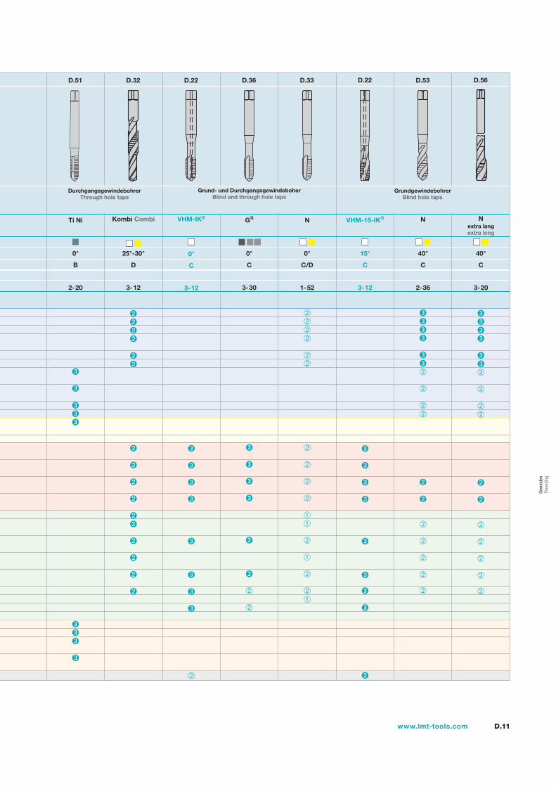
D.11www.lmt-tools.com
Ti Ni
0°
B
2-20
Kombi Combi
DurchgangsgewindebohrerThrough hole taps
D.51 D.32
Grund- und DurchgangsgewindeboherBlind and through hole taps
D.22
C
0°
3-12
VHM-IK2) G3) N
0°
C/D
1-52
D.33 D.22
VHM-15-IK2)
15°
C
3-12
D.53
N
40°
C
2-36
D.56
Nextra lang extra long
40°
C
3-20
D.36
GrundgewindebohrerBlind hole taps
25°-30°
3-12
D
0°
C
3-30
Gew
inde
n Th
read
ing
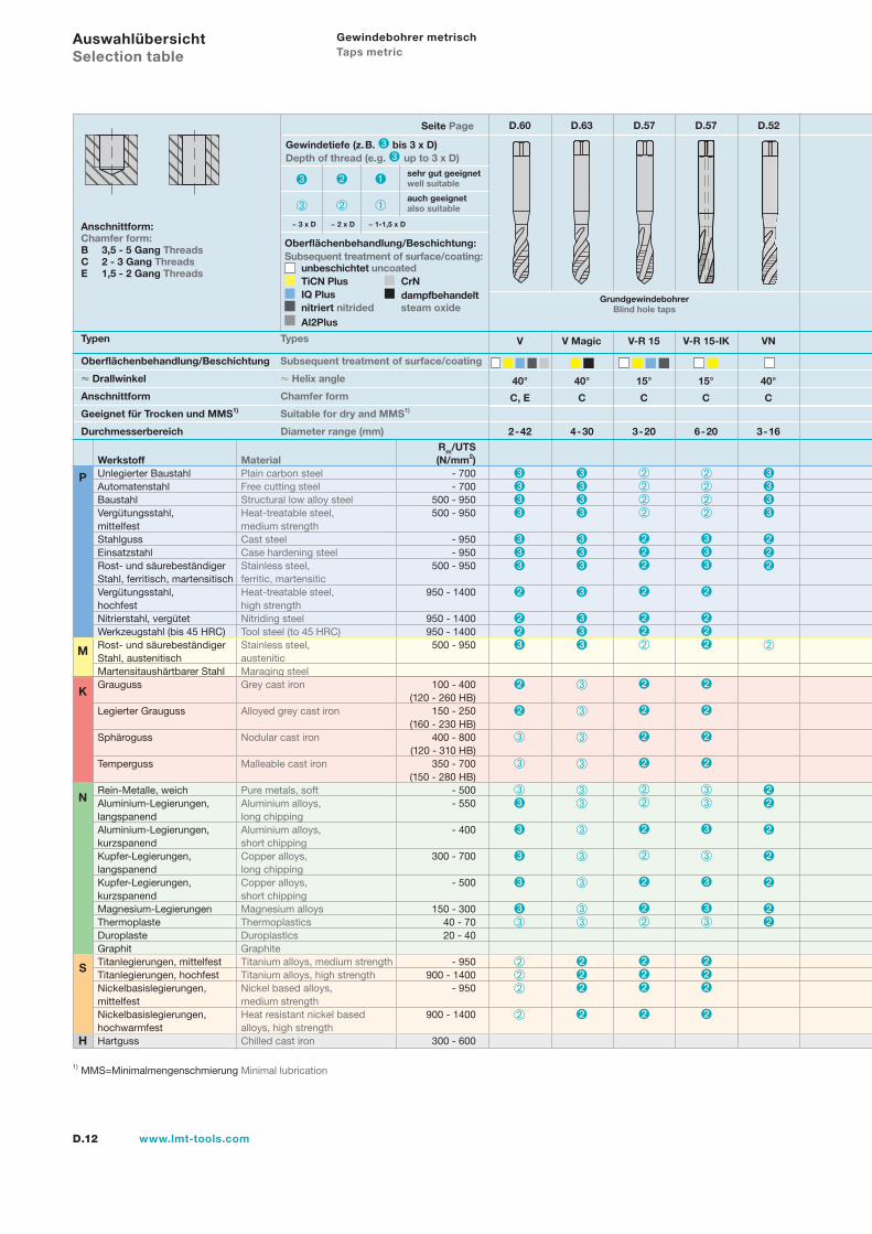
D.12 www.lmt-tools.com
Gewindebohrer metrisch Taps metric
Typen Types
Oberflächenbehandlung/Beschichtung Subsequent treatment of surface/coating
Drallwinkel Helix angle
Anschnittform Chamfer form
Geeignet für Trocken und MMS1) Suitable for dry and MMS1)
Durchmesserbereich Diameter range (mm)
Anschnittform:Chamfer form:B 3,5 - 5 Gang ThreadsC 2 - 3 Gang ThreadsE 1,5 - 2 Gang Threads
Seite Page
1) MMS=Minimalmengenschmierung Minimal lubrication
Rm/UTSWerkstoff Material (N/mm2)Unlegierter Baustahl Plain carbon steel - 700Automatenstahl Free cutting steel - 700Baustahl Structural low alloy steel 500 - 950Vergütungsstahl, Heat-treatable steel, 500 - 950mittelfest medium strengthStahlguss Cast steel - 950Einsatzstahl Case hardening steel - 950Rost- und säurebeständiger Stainless steel, 500 - 950Stahl, ferritisch, martensitisch ferritic, martensiticVergütungsstahl, Heat-treatable steel, 950 - 1400hochfest high strengthNitrierstahl, vergütet Nitriding steel 950 - 1400Werkzeugstahl (bis 45 HRC) Tool steel (to 45 HRC) 950 - 1400Rost- und säurebeständiger Stainless steel, 500 - 950Stahl, austenitisch austeniticMartensitaushärtbarer Stahl Maraging steelGrauguss Grey cast iron 100 - 400 (120 - 260 HB)Legierter Grauguss Alloyed grey cast iron 150 - 250 (160 - 230 HB)Sphäroguss Nodular cast iron 400 - 800 (120 - 310 HB)Temperguss Malleable cast iron 350 - 700 (150 - 280 HB)Rein-Metalle, weich Pure metals, soft - 500Aluminium-Legierungen, Aluminium alloys, - 550langspanend long chippingAluminium-Legierungen, Aluminium alloys, - 400kurzspanend short chippingKupfer-Legierungen, Copper alloys, 300 - 700langspanend long chippingKupfer-Legierungen, Copper alloys, - 500kurzspanend short chippingMagnesium-Legierungen Magnesium alloys 150 - 300Thermoplaste Thermoplastics 40 - 70Duroplaste Duroplastics 20 - 40Graphit GraphiteTitanlegierungen, mittelfest Titanium alloys, medium strength - 950Titanlegierungen, hochfest Titanium alloys, high strength 900 - 1400Nickelbasislegierungen, Nickel based alloys, - 950mittelfest medium strengthNickelbasislegierungen, Heat resistant nickel based 900 - 1400hochwarmfest alloys, high strengthHartguss Chilled cast iron 300 - 600
Oberflächenbehandlung/Beschichtung:Subsequent treatment of surface/coating: unbeschichtet uncoated
TiCN Plus CrN IQ Plus dampfbehandelt nitriert nitrided steam oxide
Al2Plus
Gewindetiefe (z.B. bis 3 x D)Depth of thread (e.g. up to 3 x D)
~ 1-1,5 x D~ 2 x D~ 3 x D
sehr gut geeignetwell suitable
auch geeignetalso suitable
Auswahlübersicht Selection table
P
M
K
N
S
H
40° 40° 15° 15° 40°
C, E C C C C
V V Magic V-R 15 V-R 15-IK VN
2-42 4-30 3-20 6-20 3-16
D.60 D.63 D.57 D.57 D.52
GrundgewindebohrerBlind hole taps
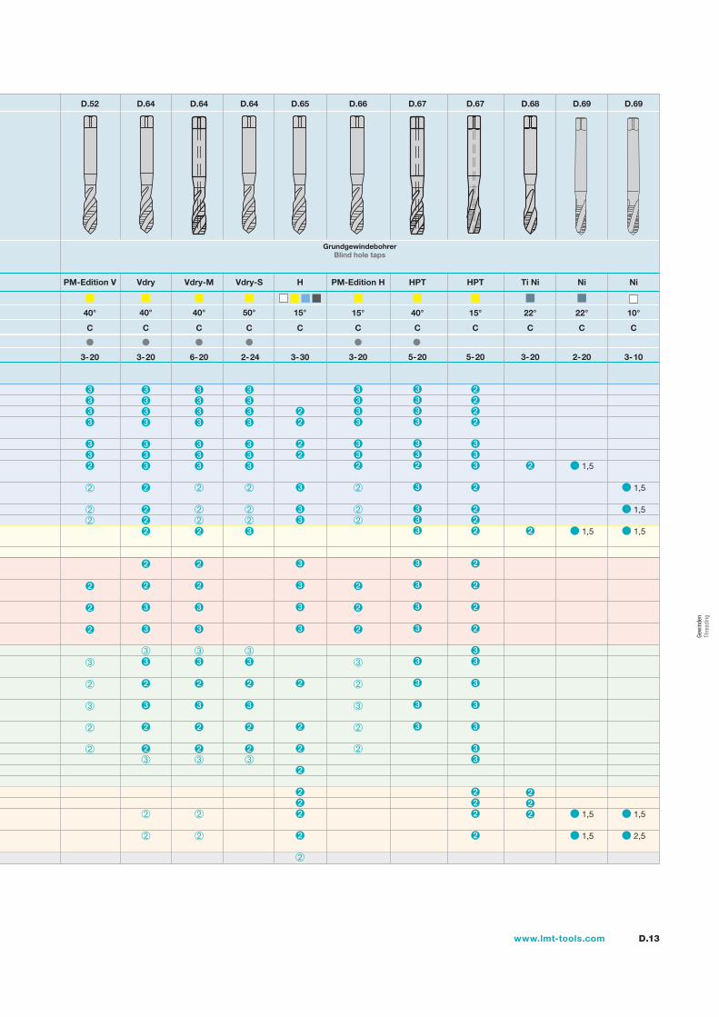
D.13www.lmt-tools.com
GrundgewindebohrerBlind hole taps
40°
C
3-20
D.52
PM-Edition V
15°
C
3-20
D.66
PM-Edition H
D.64
40°
C
3-20
Vdry
D.64
40°
C
6-20
Vdry-M
D.64
50°
C
2-24
Vdry-S
D.65
15°
C
3-30
H
22°
C
3-20
D.68
Ti Ni
1,5
1,5
1,5
1,5
22°
C
2-20
D.69
Ni
15°
C
5-20
D.67
HPT
1,5
1,5
1,5
1,5
2,5
10°
C
3-10
D.69
Ni
40°
C
5-20
D.67
HPT
Gew
inde
n Th
read
ing
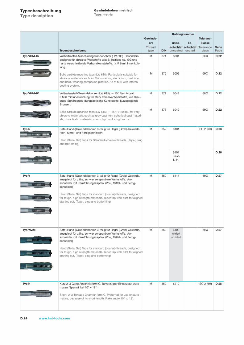
D.14 www.lmt-tools.com
Katalognummer
Gewinde- Toleranz-
art unbe- be- klasse
Thread schichtet schichtet Tolerance SeiteTypenbeschreibung type DIN uncoated coated class Page
Typ VHM-IK Vollhartmetall-Maschinengewindebohrer (LW 630). Besonders geeignet für abrasive Werkstoffe wie: Si-haltiges AL, GG und harte verschleißende Verbundkunststoffe. ≥ M 6 mit Innenküh-lung.
Solid carbide machine taps (LW 630). Particularly suitable for abrasive materials such as: Si-containing aluminium, cast iron and hard, wearing compound plastics. As of M 6 with internal cooling system.
M 371 6001 6HX D.22
M 376 6002 6HX D.22
Typ VHM-IK Vollhartmetall-Gewindebohrer (LW 615), 15° Rechtsdrall ≥ M 6 mit Innenkühlung für stark abrasive Werkstoffe, wie Grau-guss, Sphäroguss, duroplastische Kunststoffe, kurzspanende Bronzen.
Solid carbide machine taps (LW 615), 15° RH spiral, for very abrasive materials, such as grey cast iron, spherical cast materi-als, duroplastic materials, short chip producing bronze.
M 371 6041 6HX D.22
M 376 6042 6HX D.22
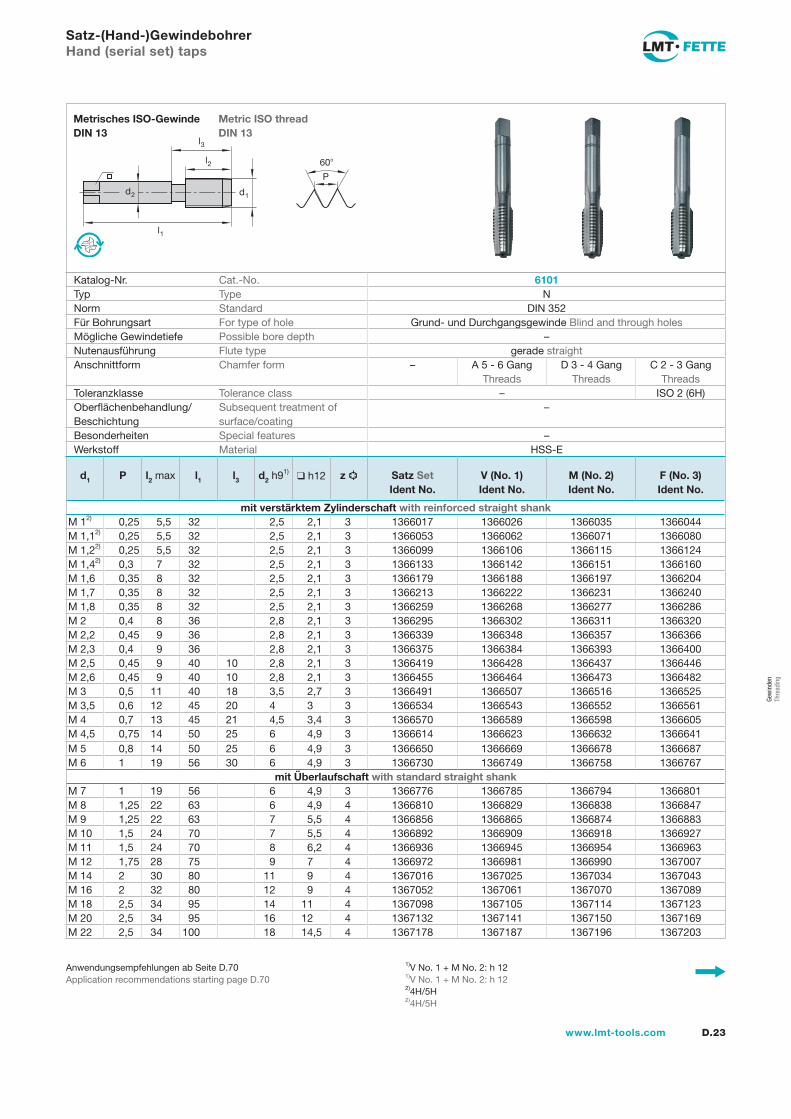
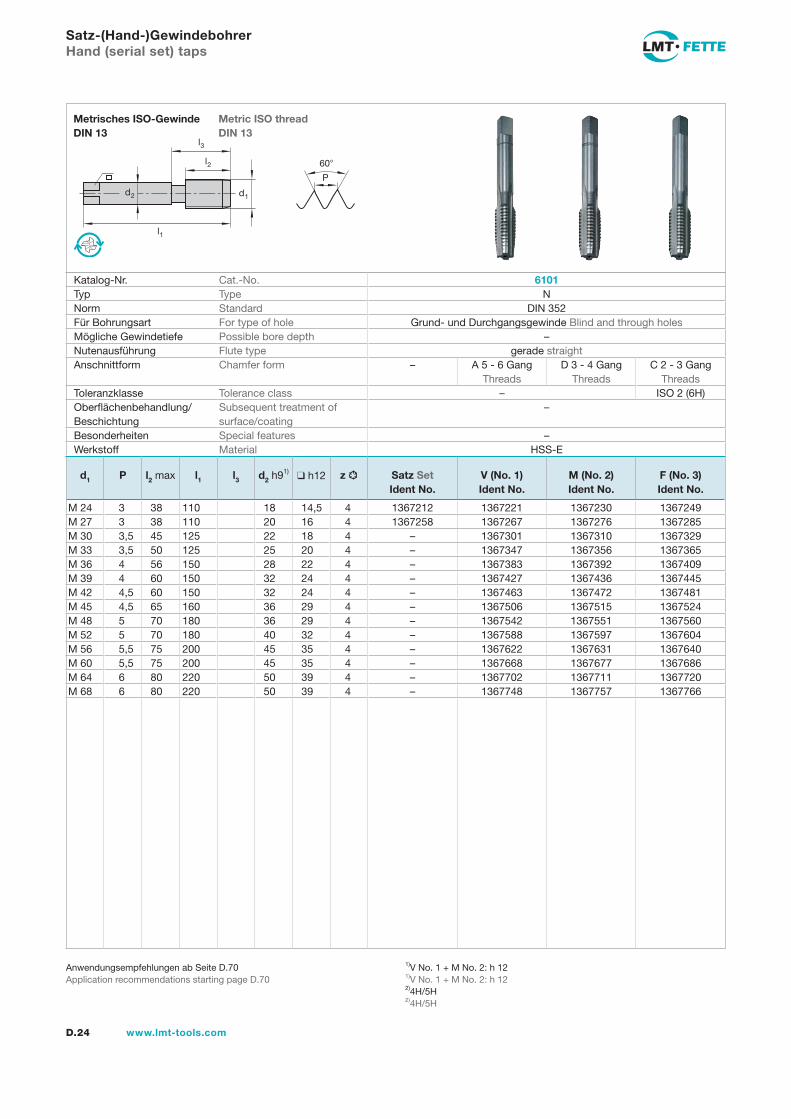
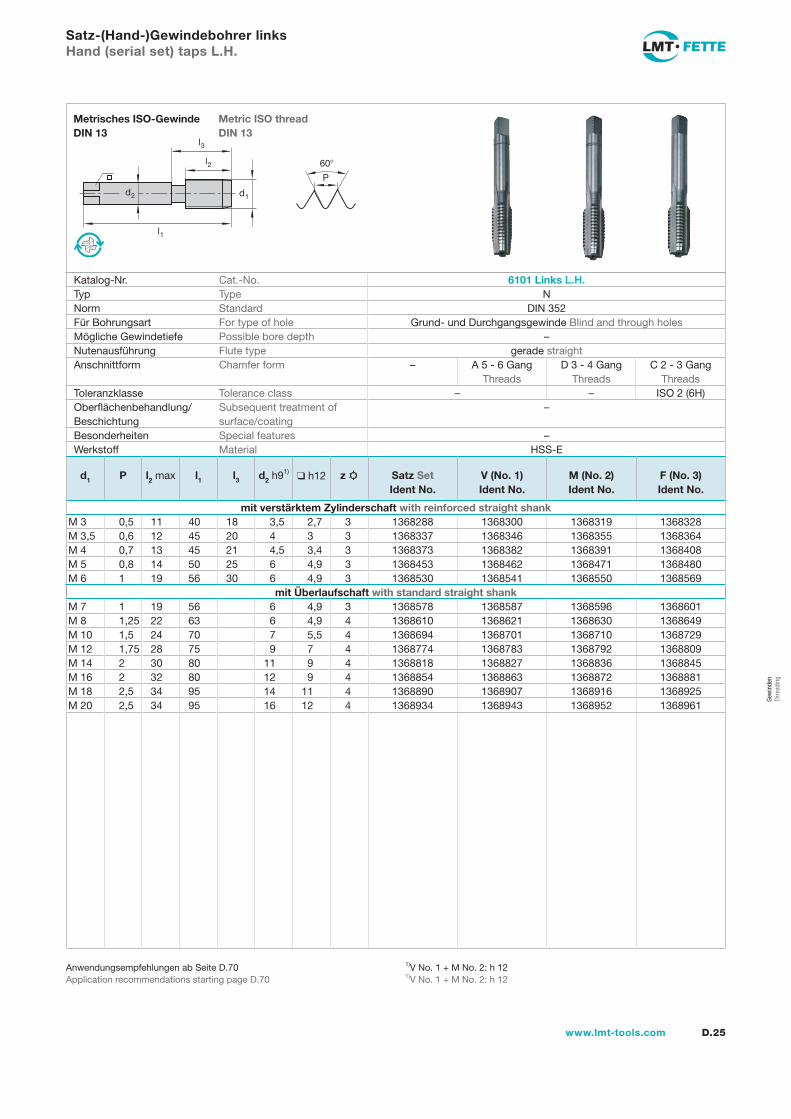
Typ N Satz-(Hand-)Gewindebohrer, 3-teilig für Regel (Grob)-Gewinde. (Vor-, Mittel- und Fertigschneider)
Hand (Serial Set) Taps for Standard (coarse) threads. (Taper, plug and bottoming)
M 352 6101 ISO 2 (6H) D.23
6101LinksL. H.
D.26
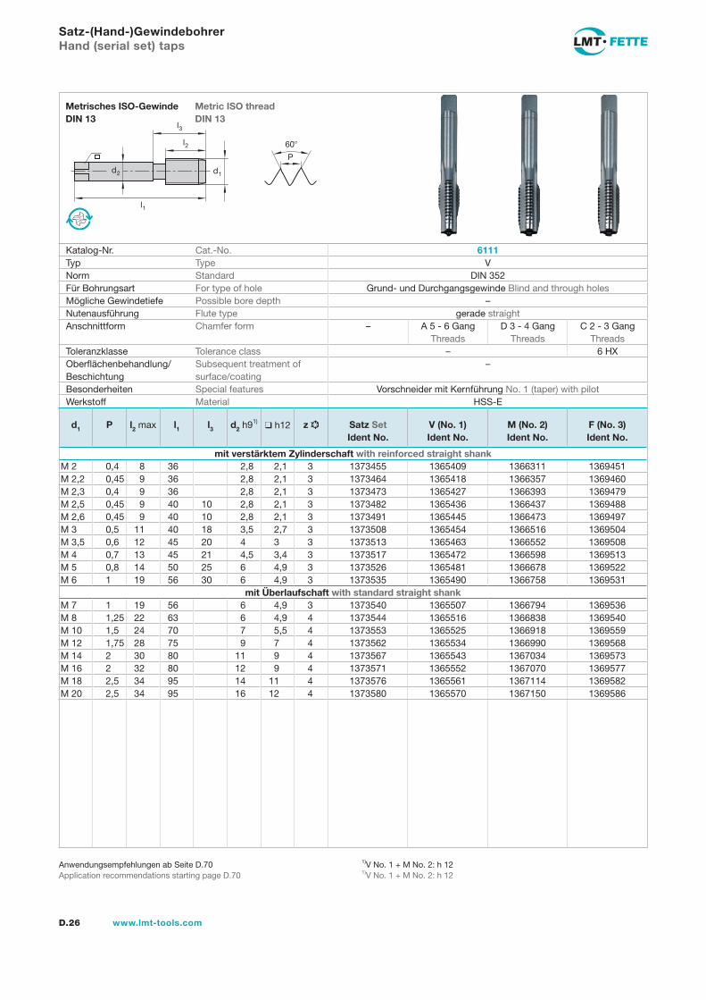
Typ V Satz-(Hand-)Gewindebohrer, 3-teilig für Regel (Grob)-Gewinde,ausgelegt für zähe, schwer zerspanbare Werkstoffe. Vor-schneider mit Kernführungszapfen. (Vor-, Mittel- und Fertig-schneider)
Hand (Serial Set) Taps for standard (coarse)-threads, designed for tough, high strength materials. Taper tap with pilot for aligned starting cut. (Taper, plug and bottoming)
M 352 6111 6HX D.27
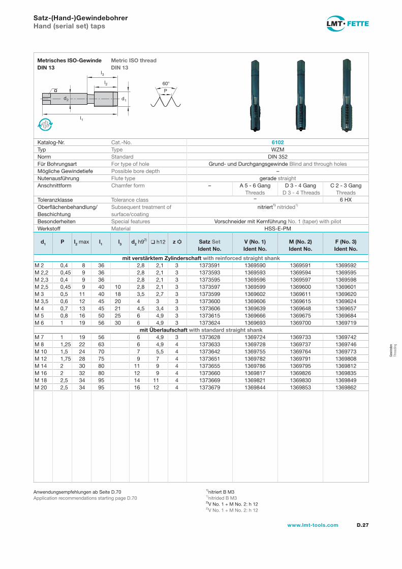
Typ WZM Satz-(Hand-)Gewindebohrer, 3-teilig für Regel (Grob)-Gewinde,ausgelegt für zähe, schwer zerspanbare Werkstoffe. Vor-schneider mit Kernführungszapfen. (Vor-, Mittel- und Fertig-schneider)
Hand (Serial Set) Taps for standard (coarse)-threads, designed for tough, high strength materials. Taper tap with pilot for aligned starting cut. (Taper, plug and bottoming)
M 352 6102nitriert nitrided
6HX D.27
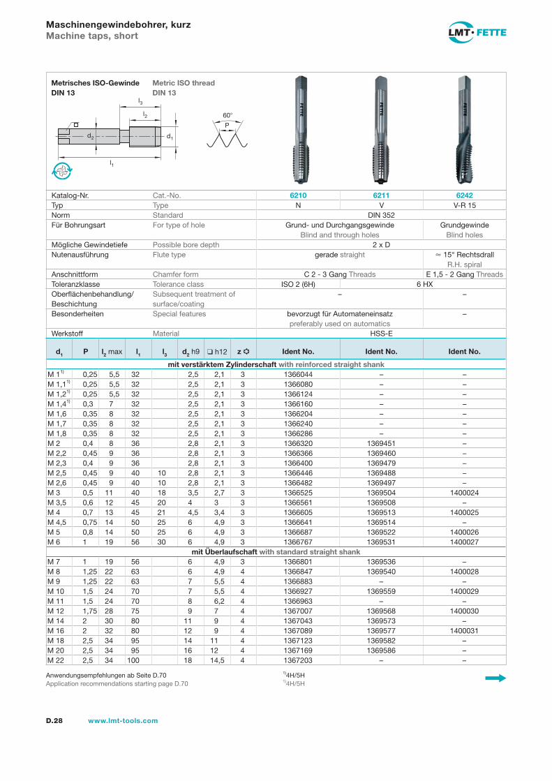
Typ N Kurz 2–3 Gang Anschnittform C. Bevorzugter Einsatz auf Auto-maten. Spanwinkel 10° – 12°.
Short 2–3 Threads Chamfer form C. Preferred for use on auto-matics, because of its short length. Rake angle 10° to 12°.
M 352 6210 ISO 2 (6H) D.28
Typenbeschreibung Type desciption
Gewindebohrer metrisch Taps metric
D.15www.lmt-tools.com
Katalognummer
Gewinde- Toleranz-
art unbe- be- klasse
Thread schichtet schichtet Tolerance SeiteTypenbeschreibung type DIN uncoated coated class Page
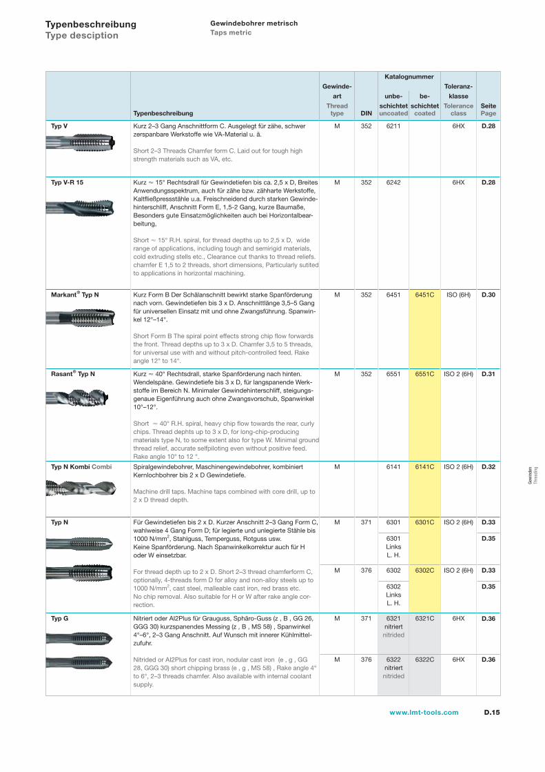
Typ V Kurz 2–3 Gang Anschnittform C. Ausgelegt für zähe, schwerzerspanbare Werkstoffe wie VA-Material u. ä.
Short 2–3 Threads Chamfer form C. Laid out for tough high strength materials such as VA, etc.
M 352 6211 6HX D.28
Typ V-R 15 Kurz 15° Rechtsdrall für Gewindetiefen bis ca. 2,5 x D, Breites Anwendungsspektrum, auch für zähe bzw. zähharte Werkstoffe, Kaltfließpressstähle u.a. Freischneidend durch starken Gewinde-hinterschliff, Anschnitt Form E, 1,5-2 Gang, kurze Baumaße,Besonders gute Einsatzmöglichkeiten auch bei Horizontalbear-beitung,
Short 15° R.H. spiral, for thread depths up to 2,5 x D, wide range of applications, including tough and semirigid materials, cold extruding stells etc., Clearance cut thanks to thread reliefs. chamfer E 1,5 to 2 threads, short dimensions, Particularly sutited to applications in horizontal machining.
M 352 6242 6HX D.28
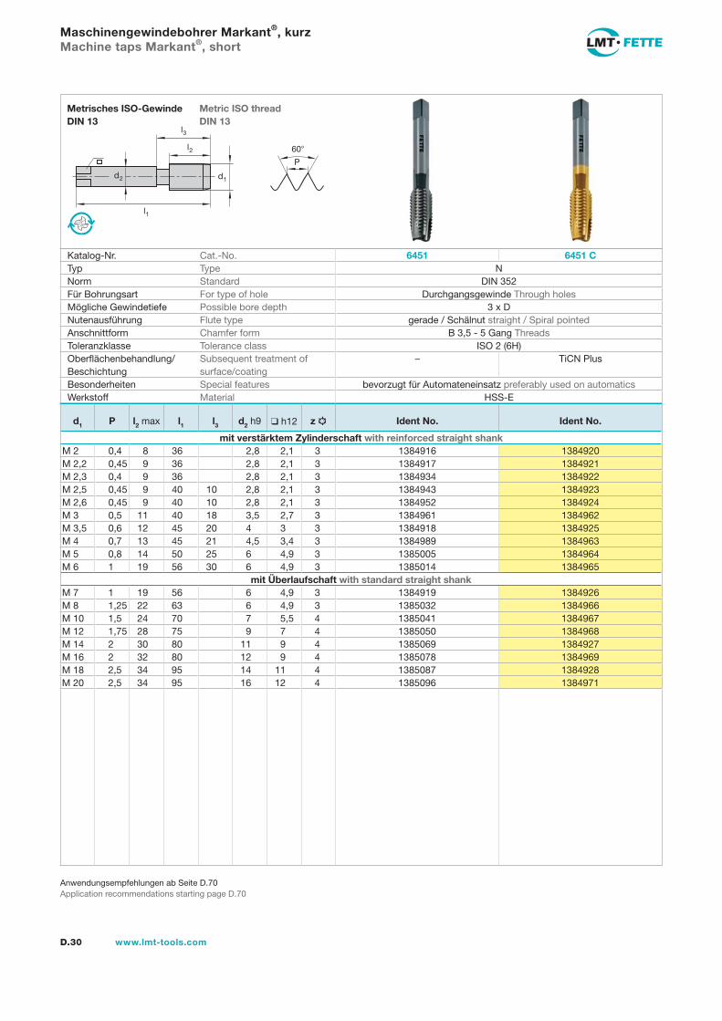
Markant® Typ N Kurz Form B Der Schälanschnitt bewirkt starke Spanförderung nach vorn. Gewindetiefen bis 3 x D. Anschnittlänge 3,5–5 Gang für universellen Einsatz mit und ohne Zwangsführung. Spanwin-kel 12°–14°.
Short Form B The spiral point effects strong chip flow forwards the front. Thread depths up to 3 x D. Chamfer 3,5 to 5 threads, for universal use with and without pitch-controlled feed. Rake angle 12° to 14°.
M 352 6451 6451C ISO (6H) D.30
Rasant® Typ N Kurz 40° Rechtsdrall, starke Spanförderung nach hinten. Wendelspäne. Gewindetiefe bis 3 x D, für langspanende Werk-stoffe im Bereich N. Minimaler Gewindehinterschliff, steigungs-genaue Eigenführung auch ohne Zwangsvorschub, Spanwinkel 10°–12°. Short 40° R.H. spiral, heavy chip flow towards the rear, curly chips. Thread dephts up to 3 x D, for long-chip-producing materials type N, to some extent also for type W. Minimal groundthread relief, accurate selfpiloting even without positive feed. Rake angle 10° to 12 °.
M 352 6551 6551C ISO 2 (6H) D.31
Typ N Kombi Combi Spiralgewindebohrer, Maschinengewindebohrer, kombiniertKernlochbohrer bis 2 x D Gewindetiefe.
Machine drill taps. Machine taps combined with core drill, up to 2 x D thread depth.
M 6141 6141C ISO 2 (6H) D.32
Typ N Für Gewindetiefen bis 2 x D. Kurzer Anschnitt 2–3 Gang Form C,wahlweise 4 Gang Form D; für legierte und unlegierte Stähle bis1000 N/mm2, Stahlguss, Temperguss, Rotguss usw. Keine Spanförderung. Nach Spanwinkelkorrektur auch für H oder W einsetzbar.
For thread depth up to 2 x D. Short 2–3 thread chamferform C,optionally, 4-threads form D for alloy and non-alloy steels up to1000 N/mm2, cast steel, malleable cast iron, red brass etc. No chip removal. Also suitable for H or W after rake angle cor-rection.
M 371 6301 6301C ISO 2 (6H) D.33
6301LinksL. H.
D.35
M 376 6302 6302C ISO 2 (6H) D.33
6302LinksL. H.
D.35
Typ G Nitriert oder AI2Plus für Grauguss, Sphäro-Guss (z , B , GG 26, GGG 30) kurzspanendes Messing (z , B , MS 58) , Spanwinkel 4°–6°, 2–3 Gang Anschnitt. Auf Wunsch mit innerer Kühlmittel- zufuhr.
Nitrided or AI2Plus for cast iron, nodular cast iron (e , g , GG 28, GGG 30) short chipping brass (e , g , MS 58) , Rake angle 4° to 6°, 2–3 threads chamfer. Also available with internal coolant supply.
M 371 6321nitriertnitrided
6321C 6HX D.36
M 376 6322nitriertnitrided
6322C 6HX D.36
Typenbeschreibung Type desciption
Gewindebohrer metrisch Taps metric
Gew
inde
n Th
read
ing
D.16 www.lmt-tools.com
Katalognummer
Gewinde- Toleranz-
art unbe- be- klasse
Thread schichtet schichtet Tolerance SeiteTypenbeschreibung type DIN uncoated coated class Page
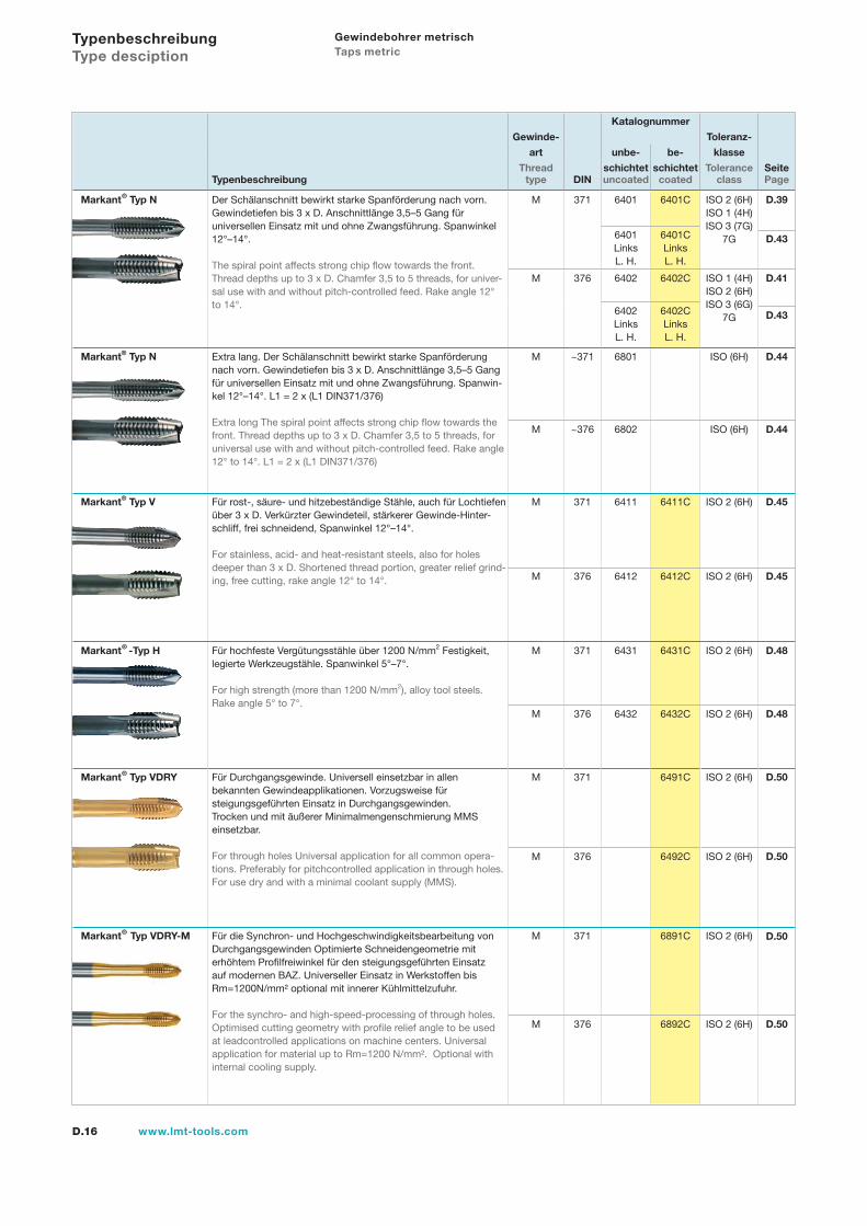
Markant® Typ N Der Schälanschnitt bewirkt starke Spanförderung nach vorn.Gewindetiefen bis 3 x D. Anschnittlänge 3,5–5 Gang für universellen Einsatz mit und ohne Zwangsführung. Spanwinkel 12°–14°.
The spiral point affects strong chip flow towards the front. Thread depths up to 3 x D. Chamfer 3,5 to 5 threads, for univer-sal use with and without pitch-controlled feed. Rake angle 12° to 14°.
M 371 6401 6401C ISO 2 (6H)ISO 1 (4H)ISO 3 (7G)
7G
D.39
6401LinksL. H.
6401CLinksL. H.
D.43
M 376 6402 6402C ISO 1 (4H) ISO 2 (6H)ISO 3 (6G)
7G
D.41
6402LinksL. H.
6402CLinksL. H.
D.43
Markant® Typ N Extra lang. Der Schälanschnitt bewirkt starke Spanförderung nach vorn. Gewindetiefen bis 3 x D. Anschnittlänge 3,5–5 Gang für universellen Einsatz mit und ohne Zwangsführung. Spanwin-kel 12°–14°. L1 = 2 x (L1 DIN371/376)
Extra long The spiral point affects strong chip flow towards the front. Thread depths up to 3 x D. Chamfer 3,5 to 5 threads, for universal use with and without pitch-controlled feed. Rake angle 12° to 14°. L1 = 2 x (L1 DIN371/376)
M ~371 6801 ISO (6H) D.44
M ~376 6802 ISO (6H) D.44
Markant® Typ V Für rost-, säure- und hitzebeständige Stähle, auch für Lochtiefen über 3 x D. Verkürzter Gewindeteil, stärkerer Gewinde-Hinter-schliff, frei schneidend, Spanwinkel 12°–14°.
For stainless, acid- and heat-resistant steels, also for holes deeper than 3 x D. Shortened thread portion, greater relief grind-ing, free cutting, rake angle 12° to 14°.
M 371 6411 6411C ISO 2 (6H) D.45
M 376 6412 6412C ISO 2 (6H) D.45
Markant® -Typ H Für hochfeste Vergütungsstähle über 1200 N/mm2 Festigkeit,legierte Werkzeugstähle. Spanwinkel 5°–7°.
For high strength (more than 1200 N/mm2), alloy tool steels.Rake angle 5° to 7°.
M 371 6431 6431C ISO 2 (6H) D.48
M 376 6432 6432C ISO 2 (6H) D.48
Markant® Typ VDRY Für Durchgangsgewinde. Universell einsetzbar in allen bekannten Gewindeapplikationen. Vorzugsweise für steigungsgeführten Einsatz in Durchgangsgewinden. Trocken und mit äußerer Minimalmengenschmierung MMS einsetzbar.
For through holes Universal application for all common opera-tions. Preferably for pitchcontrolled application in through holes. For use dry and with a minimal coolant supply (MMS).
M 371 6491C ISO 2 (6H) D.50
M 376 6492C ISO 2 (6H) D.50
Markant® Typ VDRY-M Für die Synchron- und Hochgeschwindigkeitsbearbeitung von Durchgangsgewinden Optimierte Schneidengeometrie mit erhöhtem Profilfreiwinkel für den steigungsgeführten Einsatz auf modernen BAZ. Universeller Einsatz in Werkstoffen bis Rm=1200N/mm² optional mit innerer Kühlmittelzufuhr.
For the synchro- and high-speed-processing of through holes. Optimised cutting geometry with profile relief angle to be used at leadcontrolled applications on machine centers. Universal application for material up to Rm=1200 N/mm². Optional with internal cooling supply.
M 371 6891C ISO 2 (6H) D.50
M 376 6892C ISO 2 (6H) D.50
Typenbeschreibung Type desciption
Gewindebohrer metrisch Taps metric
D.17www.lmt-tools.com
Katalognummer
Gewinde- Toleranz-
art unbe- be- klasse
Thread schichtet schichtet Tolerance SeiteTypenbeschreibung type DIN uncoated coated class Page
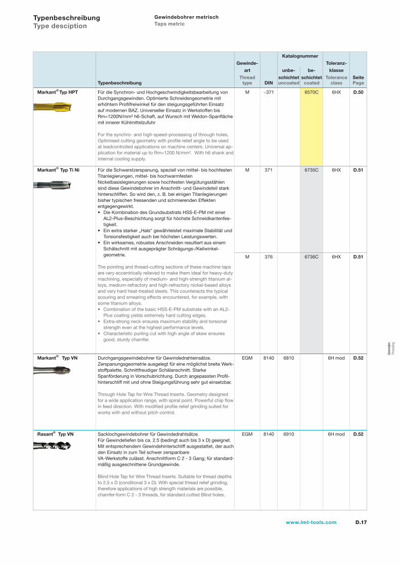
Markant® Typ HPT Für die Synchron- und Hochgeschwindigkeitsbearbeitung von Durchgangsgewinden. Optimierte Schneidengeometrie mit erhöhtem Profilfreiwinkel für den steigungsgeführten Einsatz auf modernen BAZ. Universeller Einsatz in Werkstoffen bis Rm=1200N/mm² h6-Schaft, auf Wunsch mit Weldon-Spanflächemit innerer Kühlmittelzufuhr
For the synchro- and high-speed-processing of through holes,Optimised cutting geometry with profile relief angle to be used at leadcontrolled applications on machine centers. Universal ap-plication for material up to Rm=1200 N/mm². With h6 shank and internal cooling supply.
M ~371 6570C 6HX D.50
Markant® Typ Ti Ni Für die Schwerstzerspanung, speziell von mittel- bis hochfestenTitanlegierungen, mittel- bis hochwarmfesten Nickelbasislegierungen sowie hochfesten Vergütungsstählen sind diese Gewindebohrer im Anschnitt- und Gewindeteil stark hinterschliffen. So wird den, z. B. bei einigen Titanlegierungen bisher typischen fressenden und schmierenden Effekten entgegengewirkt.
Die Kombination des Grundsubstrats HSS-E-PM mit einerAL2-Plus-Beschichtung sorgt für höchste Schneidkantenfes-tigkeit.Ein extra starker „Hals“ gewährleistet maximale Stabilität undTorsionsfestigkeit auch bei höchsten Leistungswerten.Ein wirksames, robustes Anschneiden resultiert aus einemSchälschnitt mit ausgeprägter Schrägungs-/Keilwinkel-geometrie.
The pointing and thread-cutting sections of these machine tapsare very eccentrically relieved to make them ideal for heavy-dutymachining, especially of medium- and high-strength titanium al-loys, medium-refractory and high-refractory nickel-based alloysand very hard heat-treated steels. This counteracts the typical scouring and smearing effects encountered, for example, with some titanium alloys.
Combination of the basic HSS-E-PM substrate with an AL2-Plus coating yields extremely hard cutting edges.Extra-strong neck ensures maximum stability and torsionalstrength even at the highest performance levels.Characteristic purling cut with high angle of skew ensuresgood, sturdy chamfer.
•
•
•
•
•
•
M 371 6735C 6HX D.51
M 376 6736C 6HX D.51
Markant® Typ VN Durchgangsgewindebohrer für Gewindedrahteinsätze. Zerspanungsgeometrie ausgelegt für eine möglichst breite Werk- stoffpalette. Schnittfreudiger Schälanschnitt. Starke Spanförderung in Vorschubrichtung. Durch angepassten Profil-hinterschliff mit und ohne Steigungsführung sehr gut einsetzbar.
Through Hole Tap for Wire Thread Inserts. Geometry designed for a wide application range, with spiral point. Powerful chip flow in feed direction. With modified profile relief grinding suited for works with and without pitch control.
EGM 8140 6810 6H mod D.52
Rasant® Typ VN Sacklochgewindebohrer für Gewindedrahtsätze. Für Gewindetiefen bis ca. 2.5 (bedingt auch bis 3 x D) geeignet. Mit entsprechendem Gewindehinterschliff ausgestattet, der auch den Einsatz in zum Teil schwer zerspanbare VA-Werkstoffe zulässt. Anschnittform C 2 - 3 Gang; für standard-mäßig ausgeschnittene Grundgewinde.
Blind Hole Tap for Wire Thread Inserts. Suitable for thread depths to 2,5 x D (conditional 3 x D). With special thread relief grinding, therefore applications of high strength materials are possible, chamfer-form C 2 - 3 threads, for standard cutted Blind holes.
EGM 8140 6910 6H mod D.52
Typenbeschreibung Type desciption
Gewindebohrer metrisch Taps metric
Gew
inde
n Th
read
ing
D.18 www.lmt-tools.com
Katalognummer
Gewinde- Toleranz-
art unbe- be- klasse
Thread schichtet schichtet Tolerance SeiteTypenbeschreibung type DIN uncoated coated class Page
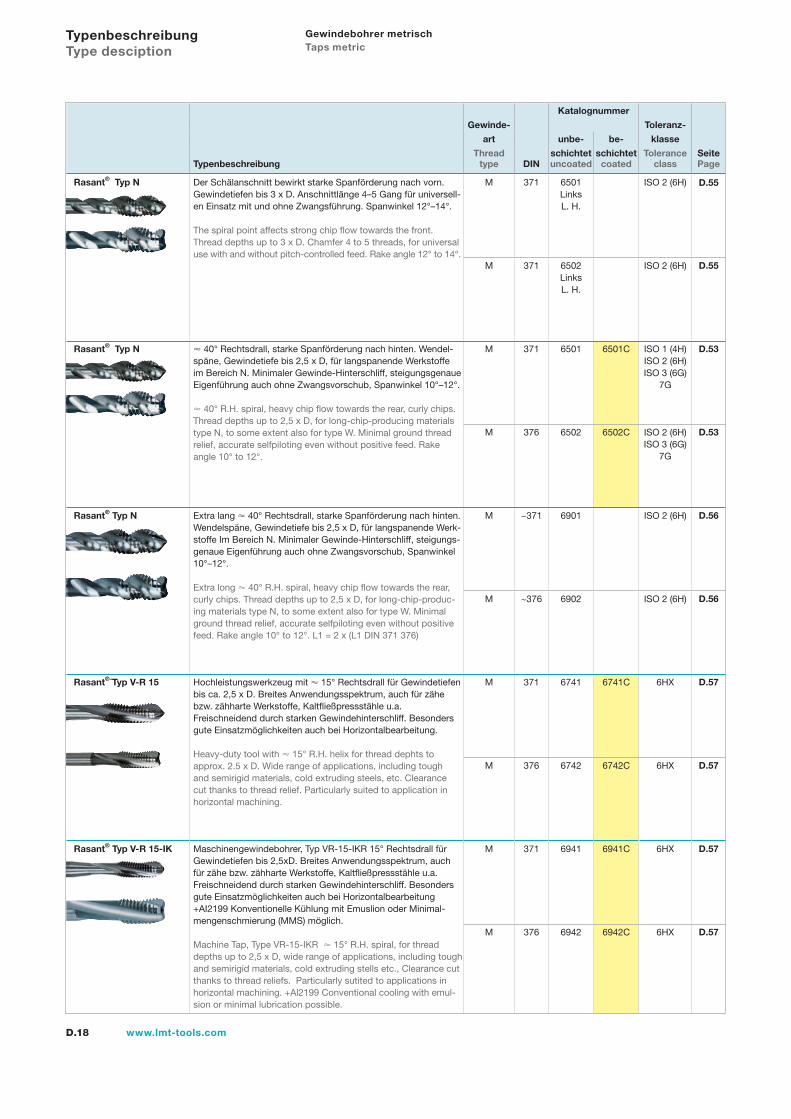
Rasant® Typ N Der Schälanschnitt bewirkt starke Spanförderung nach vorn.Gewindetiefen bis 3 x D. Anschnittlänge 4–5 Gang für universell-en Einsatz mit und ohne Zwangsführung. Spanwinkel 12°–14°.
The spiral point affects strong chip flow towards the front.Thread depths up to 3 x D. Chamfer 4 to 5 threads, for universal use with and without pitch-controlled feed. Rake angle 12° to 14°.
M 371 6501LinksL. H.
ISO 2 (6H) D.55
M 371 6502LinksL. H.
ISO 2 (6H) D.55
Rasant® Typ N 40° Rechtsdrall, starke Spanförderung nach hinten. Wendel-späne, Gewindetiefe bis 2,5 x D, für langspanende Werkstoffe im Bereich N. Minimaler Gewinde-Hinterschliff, steigungsgenaue Eigenführung auch ohne Zwangsvorschub, Spanwinkel 10°–12°.
40° R.H. spiral, heavy chip flow towards the rear, curly chips.Thread depths up to 2,5 x D, for long-chip-producing materials type N, to some extent also for type W. Minimal ground thread relief, accurate selfpiloting even without positive feed. Rake angle 10° to 12°.
M 371 6501 6501C ISO 1 (4H)ISO 2 (6H)ISO 3 (6G)
7G
D.53
M 376 6502 6502C ISO 2 (6H)ISO 3 (6G)
7G
D.53
Rasant® Typ N Extra lang 40° Rechtsdrall, starke Spanförderung nach hinten. Wendelspäne, Gewindetiefe bis 2,5 x D, für langspanende Werk-stoffe Im Bereich N. Minimaler Gewinde-Hinterschliff, steigungs-genaue Eigenführung auch ohne Zwangsvorschub, Spanwinkel 10°–12°.
Extra long 40° R.H. spiral, heavy chip flow towards the rear, curly chips. Thread depths up to 2,5 x D, for long-chip-produc-ing materials type N, to some extent also for type W. Minimal ground thread relief, accurate selfpiloting even without positive feed. Rake angle 10° to 12°. L1 = 2 x (L1 DIN 371 376)
M ~371 6901 ISO 2 (6H) D.56
M ~376 6902 ISO 2 (6H) D.56
Rasant®´Typ V-R 15 Hochleistungswerkzeug mit 15° Rechtsdrall für Gewindetiefen bis ca. 2,5 x D. Breites Anwendungsspektrum, auch für zähe bzw. zähharte Werkstoffe, Kaltfließpressstähle u.a. Freischneidend durch starken Gewindehinterschliff. Besonders gute Einsatzmöglichkeiten auch bei Horizontalbearbeitung.
Heavy-duty tool with 15° R.H. helix for thread dephts to approx. 2.5 x D. Wide range of applications, including tough and semirigid materials, cold extruding steels, etc. Clearance cut thanks to thread relief. Particularly suited to application in horizontal machining.
M 371 6741 6741C 6HX D.57
M 376 6742 6742C 6HX D.57
Rasant® Typ V-R 15-IK Maschinengewindebohrer, Typ VR-15-IKR 15° Rechtsdrall für Gewindetiefen bis 2,5xD. Breites Anwendungsspektrum, auch für zähe bzw. zähharte Werkstoffe, Kaltfließpressstähle u.a.Freischneidend durch starken Gewindehinterschliff. Besonders gute Einsatzmöglichkeiten auch bei Horizontalbearbeitung+AI2199 Konventionelle Kühlung mit Emuslion oder Minimal-mengenschmierung (MMS) möglich.
Machine Tap, Type VR-15-IKR 15° R.H. spiral, for thread depths up to 2,5 x D, wide range of applications, including tough and semirigid materials, cold extruding stells etc., Clearance cut thanks to thread reliefs. Particularly sutited to applications in horizontal machining. +Al2199 Conventional cooling with emul-sion or minimal lubrication possible.
M 371 6941 6941C 6HX D.57
M 376 6942 6942C 6HX D.57
Typenbeschreibung Type desciption
Gewindebohrer metrisch Taps metric
D.19www.lmt-tools.com
Katalognummer
Gewinde- Toleranz-
art unbe- be- klasse
Thread schichtet schichtet Tolerance SeiteTypenbeschreibung type DIN uncoated coated class Page
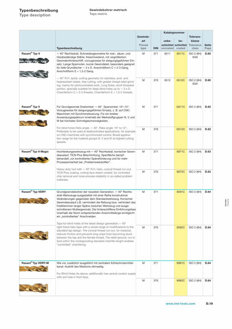
Rasant® Typ V 40° Rechtsdrall, Schneidengeometrie für rost-, säure- und hitzebeständige Stähle, freischneidend, mit vergrößertem Gewindenhinterschliff, vorzugsweise für steigungsgeführten Ein-satz. Lange Spannuten, kurzer Gewindeteil, besonders geeignet für tiefe Grundlöcher 3 x D. Anschnittform C = 2-3 Gang, Anschnittform E = 1,5-2 Gang.
40° R.H. spiral, cutting geometry for stainless, acid- and heatresistant steels, free cutting, with greater thread relief grind-ing, mainly for pitchcontrolled work. Long flutes, short threaded portion, specially suitable for deep blind holes up to 3 x D. Chamferform C = 2-3 threads, Chamferform E = 1,5-2 threads.
M 371 6511 6511C ISO 2 (6H)6GX
D.60
M 376 6512 6512C ISO 2 (6H)6GX
D.60
Rasant® Typ V Für Grundgewinde Drallwinkel: 40°. Spanwinkel: 10°–12°. Vorzugsweise für steigungsgeführten Einsatz, z. B. auf CNC-Maschinen mit Synchronsteuerung. Für ein breites Anwendungsspektrum innerhalb der Werkstoffgruppen N, V und W bei höchsten Schnittgeschwindigkeiten.
For blind holes Helix angle: 40°. Rake angle: 10° to 12°. Preferably to be used at leadcontrolled applications, for example on CNC-machines with synchronized control. Broad applica-tion range for the material groups N, V and W at highest cutting speeds.
M 371 G511C ISO 2 (6H) D.62
M 376 G512C ISO 2 (6H) D.62
Rasant® Typ V-Magic Hochleistungswerkzeug mit 40° Rechtsdrall, konischer Gewin-deauslauf, TICN Plus Beschichtung, Spanfläche dampf- behandelt, zur kontrollierten Späneförderung und für mehr Prozesssicherheit bei „Problemwerkstoffen“.
Heavy-duty tool with 40° R.H. helix, conical thread run-out, TICN Plus coating, cutting face steam-oxided, for controlled chip removal and more process reliability in so-called problem materials.
M 371 6971C ISO 2 (6H) D.63
M 376 6972C ISO 2 (6H) D.63
Rasant® Typ VDRY Grundgewindebohrer der neuesten Generation. 40° Rechts-drall-Werkzeuge ausgestattet mit einer Reihe konstruktiverVeränderungen gegenüber dem Standardwerkzeug. KonischerGewindeauslauf z.B. vermindert die Reibung bzw. verhindert dasFestklemmen langer Späne zwischen Werkzeug und ausge-schnittenem Muttergewinde. Die hinterschliffene Einführungsfase innerhalb der Norm entsprechenden Anschnittslänge ermöglicht ein „kontrolliertes“ Anschneiden.
Taps for blind holes of the latest design generation. 40° right-hand helix taps with a whole range of modifications to thestandard tap design. The conical thread run-out, for instance, reduces friction and prevents long chips from becoming stuck between the tap and the female thread. The relief-ground, run-in land within the corresponding standard chamfer lenght enables “controlled” chamfering.
M 371 6591C ISO 2 (6H) D.64
M 376 6592C ISO 2 (6H) D.64
Rasant® Typ VDRY-M Wie vor, zusätzlich ausgeführt mit zentralem Kühlschmiermittel-kanal. Austritt des Mediums stirnseitig.
For Blind Holes As above, additionally has central coolant supply with exit hole in front face.
M 371 6991C ISO 2 (6H) D.64
M 376 6992C ISO 2 (6H) D.64
Typenbeschreibung Type desciption
Gewindebohrer metrisch Taps metric
Gew
inde
n Th
read
ing
D.20 www.lmt-tools.com
Katalognummer
Gewinde- Toleranz-
art unbe- be- klasse
Thread schichtet schichtet Tolerance SeiteTypenbeschreibung type DIN uncoated coated class Page
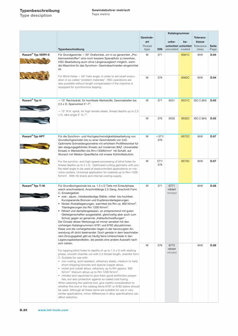
Rasant® Typ VDRY-S Für Grundgewinde 50° Drallwinkel, um in so genannten „Pro- blemwerkstoffen“ eine noch bessere Spanabfuhr zu bewirken. HSC-Bearbeitung auch ohne Längenausgleich möglich, wenn die Maschine für das Synchron- Gewindeschneiden eingerichtet ist.
For Blind Holes 50° helix angle, in order to aid swarf evacu-ation in so-called “problem materials”. HSC operations are also possible without length compensation if the machine is equipped for synchronous tapping.
M 371 6561C 6HX D.64
M 376 6562C 6HX D.64
Rasant® Typ H 15° Rechtsdrall, für hochfeste Werkstoffe, Gewindetiefen bis2,5 x D, Spanwinkel 5°–7°.
15° R.H. spiral, for high-tensile steels, thread depths up to 2,5 x D, rake angle 5° to 7°.
M 371 6531 6531C ISO 2 (6H) D.65
M 376 6532 6532C ISO 2 (6H) D.65
Rasant® Typ HPT Für die Synchron- und Hochgeschwindigkeitsbearbeitung von Grundlochgewinden bis zu einer Gewindetiefe von 2xD.Optimierte Schneidengeometrie mit erhöhtem Profilfreiwinkel für den steigungsgeführten Einsatz auf modernen BAZ. Universeller Einsatz in Werkstoffen bis Rm=1200N/mm² h6-Schaft, auf Wunsch mit Weldon-Spanfläche mit innerer Kühlmittelzufuhr.
For the synchro- and high-speed-processing of blind holes for thread depths up to 2 x D. Optimised cutting geometry with pro-file relief angle to be used at leadcontrolled applications on ma-chine centers. Universal application for material up to Rm=1200 N/mm². With h6 shank and internal cooling supply.
M 371/ 376
6572C 6HX D.67
M 371/ 376
6573C 6HX D.67
Rasant® Typ Ti Ni Für Grundlochgewinde bis ca. 1.5 x D Tiefe mit Einlaufphase, weich anschneidend, Anschnittlänge 2.5 Gang, Anschnitt Form C. Einsatzgebiet:
rost-, säure-, hitzebeständige Stähle, mittel- bis hochfest.Kurzspanende Bronzen und Kupfersonderlegierungen.Nickel-/Kobaltlegierungen, warmfest bis Rm ca. 900 N/mm2.Titanlegierungen bis Rm 1200 N/mm2.Nitriert und dampfangelassen, so entsprechend mit gutenGleiteigenschaften ausgestattet, gleichzeitig aber auch zumSchutz gegen so genannte „Kaltaufschweißungen“.
Der Einsatz dieser Werkzeuge ist immer sensibel mit den vorherigen Katalognummern 6781 und 6782 abzustimmen. Diese und die vorhergehenden liegen in der bevorzugten An-wendung oft dicht beieinander. Doch gerade in dem beschriebe-nem Einzugsgebiet gibt es häufig feine Unterschiede in den Legierungsbestandteilen, die jeweils eine andere Auswahl nach sich ziehen.
For tapping blind holes to depths of up to 1.5 x D with startingphase, smooth chamfer cut with 2.5 thread length, chamfer form C. Suitable for use with:
non-rusting, acid-resistant, refractory steels, medium to hard,short-chipping bronzes and special copper alloys.nickel and cobalt alloys, refractory up to Rm approx. 900 N/mm2, titanium alloys up to Rm 1200 N/mm2.nitrided and vaporized to give them good antifriction proper-ties, but also protection against so-called cold fusing.
When selecting the optimal tool, give careful consideration towhether this tool or the catalog items 6781 or 6782 below shouldbe used. Although all these items are suitable for use in very similar applications, minor differences in alloy specifications can affect selection.
•
•
•
•
•
•
M 371 6771nitriertnitrided
6HX D.68
M 376 6772nitriertnitrided
6HX D.68
Typenbeschreibung Type desciption
Gewindebohrer metrisch Taps metric
D.21www.lmt-tools.com
Katalognummer
Gewinde- Toleranz-
art unbe- be- klasse
Thread schichtet schichtet Tolerance SeiteTypenbeschreibung type DIN uncoated coated class Page
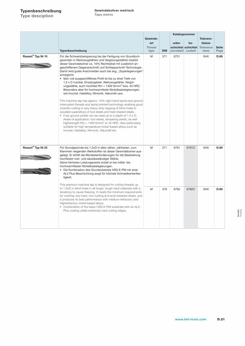
Rasant® Typ Ni 10 Für die Schwerstzerspanung bei der Fertigung von Grundloch-gewinden in Werkzeugstählen und Vergütungsstählen besitzt dieser Gewindebohrer ca. 10% Rechtsdrall mit zusätzlich an-geschliffenem Gegenanschnitt und Schleppschnitt-Technologie. Damit wird gutes Anschneiden auch bei sog. „Superlegierungen“ ermöglicht.
Sein voll ausgeschliffenes Profil ist bis zu einer Tiefe von 1,5 x D nutzbar. Einsatzgebiet: Werkzeugstähle, Vergüt-ungsstähle, auch hochfest Rm < 1400 N/mm2 bzw. 45 HRC. Besonders aber für hochwarmfeste Nickelbasislegierungen wie Inconel, Hastelloy, Nimonik, Vakumell usw.
This machine tap has approx. 10% right-hand spiral plus groundinterrupted threads and spiral pointed technology enabling goodchamfer cutting in very heavy-duty tapping of blind holes in socalled superalloys of tool steels and heat-treated steels.
Fully ground profile can be used up to a depth of 1.5 x D.Areas of application: tool steels, tempering steels, as well highstrength Rm < 1400 N/mm2 or 45 HRC. Also particularly suitable for high temperature nickel-based alloys such as Inconel, Hastelloy, Nimonik, Vakumell etc.
•
•
M 371 6751 6HX D.69
Rasant® Typ Ni 22 Für Grundgewinde bis 1,5xD in allen zähen, zähharten, zumKlemmen neigenden Werkstoffen ist dieser Gewindebohrer aus-gelegt. Er erfüllt die Mindestanforderungen für die Bearbeitung hochfester rost- und säurebeständiger Stähle. Seine höchsten Leistungswerte erzielt er bei mittel- bis hochwarmfesten Nickelbasislegierungen.
Die Kombination des Grundsubstrats HSS-E-PM mit einerAL2 Plus-Beschichtung sorgt für höchste Schneidkantenfes-tigkeit.
This premium machine tap is designed for cutting threads up to 1.5xD in blind holes in all tough, tough-hard materials with atendency to cause freezing. It meets the minimum requirements for working very hard, non-rusting and acid-resistant steels, and it produces its best performance with medium-refractory and highrefractory nickel-based alloys.
Combination of the basic HSS-E-PM substrate with an AL2-Plus coating yields extremely hard cutting edges.
•
•
M 371 6781 6781C 6HX D.69
M 376 6782 6782C 6HX D.69
Typenbeschreibung Type desciption
Gewindebohrer metrisch Taps metric
Gew
inde
n Th
read
ing
l1
d2
l2
d1
60
P
l3
D.22 www.lmt-tools.com
Metric ISO thread DIN 13
Metrisches ISO-Gewinde DIN 13
Anwendungsempfehlungen ab Seite D.70Application recommendations starting page D.70
MaschinengewindebohrerMachine taps
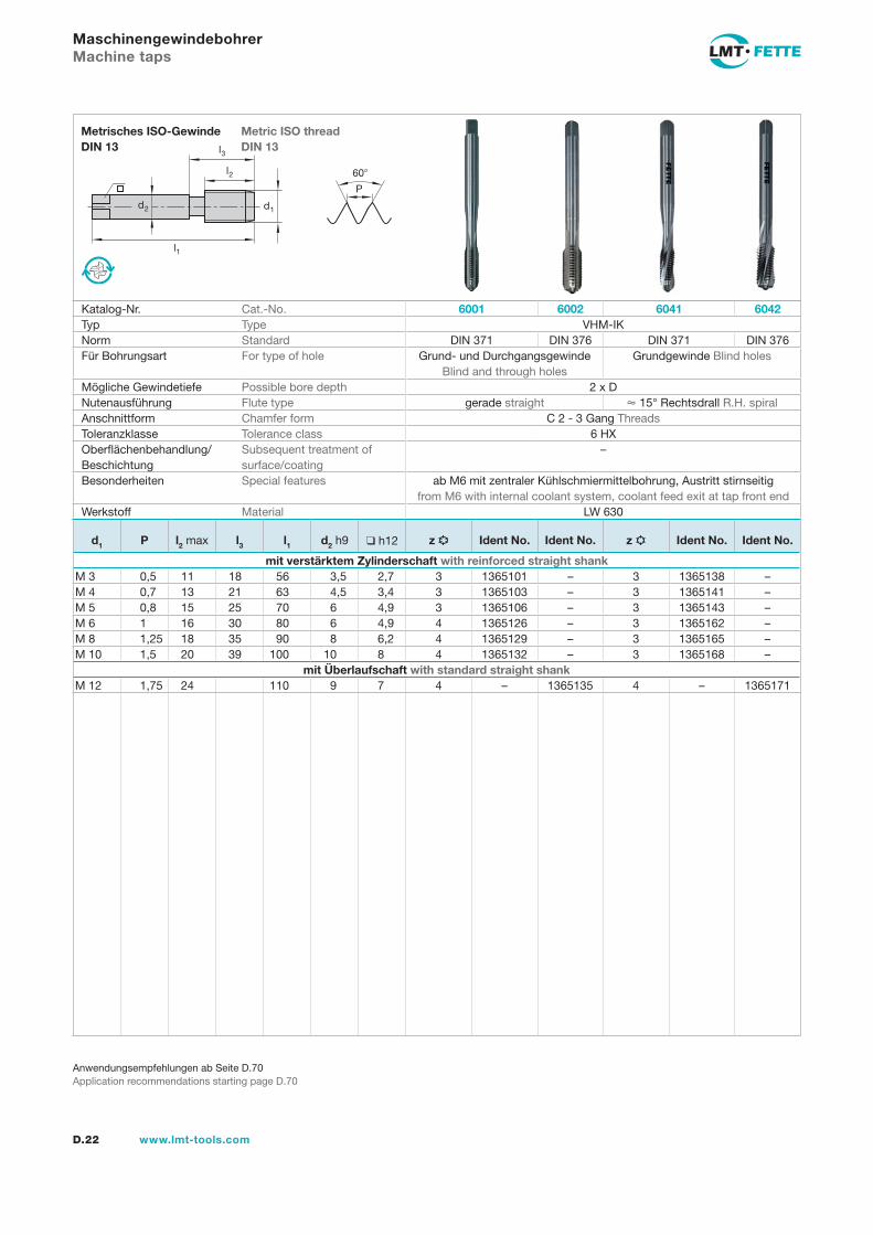
Katalog-Nr. Cat.-No. 6001 6002 6041 6042Typ Type VHM-IKNorm Standard DIN 371 DIN 376 DIN 371 DIN 376Für Bohrungsart For type of hole Grund- und Durchgangsgewinde
Blind and through holesGrundgewinde Blind holes
Mögliche Gewindetiefe Possible bore depth 2 x DNutenausführung Flute type gerade straight 15° Rechtsdrall R.H. spiralAnschnittform Chamfer form C 2 - 3 Gang ThreadsToleranzklasse Tolerance class 6 HXOberflächenbehandlung/Beschichtung
Subsequent treatment of surface/coating
–
Besonderheiten Special features ab M6 mit zentraler Kühlschmiermittelbohrung, Austritt stirnseitig from M6 with internal coolant system, coolant feed exit at tap front end
Werkstoff Material LW 630
d1 P l2 max l3 l1 d2 h9 h12 z Ident No. Ident No. z Ident No. Ident No.
mit verstärktem Zylinderschaft with reinforced straight shankM 3 0,5 11 18 56 3,5 2,7 3 1365101 – 3 1365138 –M 4 0,7 13 21 63 4,5 3,4 3 1365103 – 3 1365141 –M 5 0,8 15 25 70 6 4,9 3 1365106 – 3 1365143 –M 6 1 16 30 80 6 4,9 4 1365126 – 3 1365162 –M 8 1,25 18 35 90 8 6,2 4 1365129 – 3 1365165 –M 10 1,5 20 39 100 10 8 4 1365132 – 3 1365168 –
mit Überlaufschaft with standard straight shankM 12 1,75 24 110 9 7 4 – 1365135 4 – 1365171
Gew
inde
n Th
read
ing
l1
d2
l2
d1
60
P
l3
D.23www.lmt-tools.com
Metric ISO thread DIN 13
Metrisches ISO-Gewinde DIN 13
1)V No. 1 + M No. 2: h 121)V No. 1 + M No. 2: h 122)4H/5H2)4H/5H
Anwendungsempfehlungen ab Seite D.70Application recommendations starting page D.70
Satz-(Hand-)GewindebohrerHand (serial set) taps
Katalog-Nr. Cat.-No. 6101Typ Type NNorm Standard DIN 352Für Bohrungsart For type of hole Grund- und Durchgangsgewinde Blind and through holesMögliche Gewindetiefe Possible bore depth –Nutenausführung Flute type gerade straightAnschnittform Chamfer form – A 5 - 6 Gang
ThreadsD 3 - 4 Gang
ThreadsC 2 - 3 Gang
ThreadsToleranzklasse Tolerance class – ISO 2 (6H)Oberflächenbehandlung/Beschichtung
Subsequent treatment of surface/coating
–
Besonderheiten Special features –Werkstoff Material HSS-E
d1 P l2 max l1 l3 d2 h91) h12 z Satz SetIdent No.
V (No. 1)Ident No.
M (No. 2)Ident No.
F (No. 3)Ident No.
mit verstärktem Zylinderschaft with reinforced straight shankM 12) 0,25 5,5 32 2,5 2,1 3 1366017 1366026 1366035 1366044M 1,12) 0,25 5,5 32 2,5 2,1 3 1366053 1366062 1366071 1366080M 1,22) 0,25 5,5 32 2,5 2,1 3 1366099 1366106 1366115 1366124M 1,42) 0,3 7 32 2,5 2,1 3 1366133 1366142 1366151 1366160M 1,6 0,35 8 32 2,5 2,1 3 1366179 1366188 1366197 1366204M 1,7 0,35 8 32 2,5 2,1 3 1366213 1366222 1366231 1366240M 1,8 0,35 8 32 2,5 2,1 3 1366259 1366268 1366277 1366286M 2 0,4 8 36 2,8 2,1 3 1366295 1366302 1366311 1366320M 2,2 0,45 9 36 2,8 2,1 3 1366339 1366348 1366357 1366366M 2,3 0,4 9 36 2,8 2,1 3 1366375 1366384 1366393 1366400M 2,5 0,45 9 40 10 2,8 2,1 3 1366419 1366428 1366437 1366446M 2,6 0,45 9 40 10 2,8 2,1 3 1366455 1366464 1366473 1366482M 3 0,5 11 40 18 3,5 2,7 3 1366491 1366507 1366516 1366525M 3,5 0,6 12 45 20 4 3 3 1366534 1366543 1366552 1366561M 4 0,7 13 45 21 4,5 3,4 3 1366570 1366589 1366598 1366605M 4,5 0,75 14 50 25 6 4,9 3 1366614 1366623 1366632 1366641M 5 0,8 14 50 25 6 4,9 3 1366650 1366669 1366678 1366687M 6 1 19 56 30 6 4,9 3 1366730 1366749 1366758 1366767
mit Überlaufschaft with standard straight shankM 7 1 19 56 6 4,9 3 1366776 1366785 1366794 1366801M 8 1,25 22 63 6 4,9 4 1366810 1366829 1366838 1366847M 9 1,25 22 63 7 5,5 4 1366856 1366865 1366874 1366883M 10 1,5 24 70 7 5,5 4 1366892 1366909 1366918 1366927M 11 1,5 24 70 8 6,2 4 1366936 1366945 1366954 1366963M 12 1,75 28 75 9 7 4 1366972 1366981 1366990 1367007M 14 2 30 80 11 9 4 1367016 1367025 1367034 1367043M 16 2 32 80 12 9 4 1367052 1367061 1367070 1367089M 18 2,5 34 95 14 11 4 1367098 1367105 1367114 1367123M 20 2,5 34 95 16 12 4 1367132 1367141 1367150 1367169M 22 2,5 34 100 18 14,5 4 1367178 1367187 1367196 1367203
l1
d2
l2
d1
60
P
l3
D.24 www.lmt-tools.com
Metric ISO thread DIN 13
Metrisches ISO-Gewinde DIN 13
1)V No. 1 + M No. 2: h 121)V No. 1 + M No. 2: h 122)4H/5H2)4H/5H
Anwendungsempfehlungen ab Seite D.70Application recommendations starting page D.70
Satz-(Hand-)GewindebohrerHand (serial set) taps
Katalog-Nr. Cat.-No. 6101Typ Type NNorm Standard DIN 352Für Bohrungsart For type of hole Grund- und Durchgangsgewinde Blind and through holesMögliche Gewindetiefe Possible bore depth –Nutenausführung Flute type gerade straightAnschnittform Chamfer form – A 5 - 6 Gang
ThreadsD 3 - 4 Gang
ThreadsC 2 - 3 Gang
ThreadsToleranzklasse Tolerance class – ISO 2 (6H)Oberflächenbehandlung/Beschichtung
Subsequent treatment of surface/coating
–
Besonderheiten Special features –Werkstoff Material HSS-E
d1 P l2 max l1 l3 d2 h91) h12 z Satz SetIdent No.
V (No. 1)Ident No.
M (No. 2)Ident No.
F (No. 3)Ident No.
M 24 3 38 110 18 14,5 4 1367212 1367221 1367230 1367249M 27 3 38 110 20 16 4 1367258 1367267 1367276 1367285M 30 3,5 45 125 22 18 4 – 1367301 1367310 1367329M 33 3,5 50 125 25 20 4 – 1367347 1367356 1367365M 36 4 56 150 28 22 4 – 1367383 1367392 1367409M 39 4 60 150 32 24 4 – 1367427 1367436 1367445M 42 4,5 60 150 32 24 4 – 1367463 1367472 1367481M 45 4,5 65 160 36 29 4 – 1367506 1367515 1367524M 48 5 70 180 36 29 4 – 1367542 1367551 1367560M 52 5 70 180 40 32 4 – 1367588 1367597 1367604M 56 5,5 75 200 45 35 4 – 1367622 1367631 1367640M 60 5,5 75 200 45 35 4 – 1367668 1367677 1367686M 64 6 80 220 50 39 4 – 1367702 1367711 1367720M 68 6 80 220 50 39 4 – 1367748 1367757 1367766
Gew
inde
n Th
read
ing
l1
d2
l2
d1
60
P
l3
D.25www.lmt-tools.com
Metric ISO thread DIN 13
Metrisches ISO-Gewinde DIN 13
1)V No. 1 + M No. 2: h 121)V No. 1 + M No. 2: h 12
Anwendungsempfehlungen ab Seite D.70Application recommendations starting page D.70
Satz-(Hand-)Gewindebohrer linksHand (serial set) taps L.H.
Katalog-Nr. Cat.-No. 6101 Links L.H.Typ Type NNorm Standard DIN 352Für Bohrungsart For type of hole Grund- und Durchgangsgewinde Blind and through holesMögliche Gewindetiefe Possible bore depth –Nutenausführung Flute type gerade straightAnschnittform Chamfer form – A 5 - 6 Gang
ThreadsD 3 - 4 Gang
ThreadsC 2 - 3 Gang
ThreadsToleranzklasse Tolerance class – – ISO 2 (6H)Oberflächenbehandlung/Beschichtung
Subsequent treatment of surface/coating
–
Besonderheiten Special features –Werkstoff Material HSS-E
d1 P l2 max l1 l3 d2 h91) h12 z Satz SetIdent No.
V (No. 1)Ident No.
M (No. 2)Ident No.
F (No. 3)Ident No.
mit verstärktem Zylinderschaft with reinforced straight shankM 3 0,5 11 40 18 3,5 2,7 3 1368288 1368300 1368319 1368328M 3,5 0,6 12 45 20 4 3 3 1368337 1368346 1368355 1368364M 4 0,7 13 45 21 4,5 3,4 3 1368373 1368382 1368391 1368408M 5 0,8 14 50 25 6 4,9 3 1368453 1368462 1368471 1368480M 6 1 19 56 30 6 4,9 3 1368530 1368541 1368550 1368569
mit Überlaufschaft with standard straight shankM 7 1 19 56 6 4,9 3 1368578 1368587 1368596 1368601M 8 1,25 22 63 6 4,9 4 1368610 1368621 1368630 1368649M 10 1,5 24 70 7 5,5 4 1368694 1368701 1368710 1368729M 12 1,75 28 75 9 7 4 1368774 1368783 1368792 1368809M 14 2 30 80 11 9 4 1368818 1368827 1368836 1368845M 16 2 32 80 12 9 4 1368854 1368863 1368872 1368881M 18 2,5 34 95 14 11 4 1368890 1368907 1368916 1368925M 20 2,5 34 95 16 12 4 1368934 1368943 1368952 1368961
l1
d2
l2
d1
60
P
l3
D.26 www.lmt-tools.com
Metric ISO thread DIN 13
Metrisches ISO-Gewinde DIN 13
1)V No. 1 + M No. 2: h 121)V No. 1 + M No. 2: h 12
Anwendungsempfehlungen ab Seite D.70Application recommendations starting page D.70
Satz-(Hand-)GewindebohrerHand (serial set) taps
Katalog-Nr. Cat.-No. 6111Typ Type VNorm Standard DIN 352Für Bohrungsart For type of hole Grund- und Durchgangsgewinde Blind and through holesMögliche Gewindetiefe Possible bore depth –Nutenausführung Flute type gerade straightAnschnittform Chamfer form – A 5 - 6 Gang
ThreadsD 3 - 4 Gang
ThreadsC 2 - 3 Gang
ThreadsToleranzklasse Tolerance class – 6 HXOberflächenbehandlung/Beschichtung
Subsequent treatment of surface/coating
–
Besonderheiten Special features Vorschneider mit Kernführung No. 1 (taper) with pilotWerkstoff Material HSS-E
d1 P l2 max l1 l3 d2 h91) h12 z Satz SetIdent No.
V (No. 1)Ident No.
M (No. 2)Ident No.
F (No. 3)Ident No.
mit verstärktem Zylinderschaft with reinforced straight shankM 2 0,4 8 36 2,8 2,1 3 1373455 1365409 1366311 1369451M 2,2 0,45 9 36 2,8 2,1 3 1373464 1365418 1366357 1369460M 2,3 0,4 9 36 2,8 2,1 3 1373473 1365427 1366393 1369479M 2,5 0,45 9 40 10 2,8 2,1 3 1373482 1365436 1366437 1369488M 2,6 0,45 9 40 10 2,8 2,1 3 1373491 1365445 1366473 1369497M 3 0,5 11 40 18 3,5 2,7 3 1373508 1365454 1366516 1369504M 3,5 0,6 12 45 20 4 3 3 1373513 1365463 1366552 1369508M 4 0,7 13 45 21 4,5 3,4 3 1373517 1365472 1366598 1369513M 5 0,8 14 50 25 6 4,9 3 1373526 1365481 1366678 1369522M 6 1 19 56 30 6 4,9 3 1373535 1365490 1366758 1369531
mit Überlaufschaft with standard straight shankM 7 1 19 56 6 4,9 3 1373540 1365507 1366794 1369536M 8 1,25 22 63 6 4,9 4 1373544 1365516 1366838 1369540M 10 1,5 24 70 7 5,5 4 1373553 1365525 1366918 1369559M 12 1,75 28 75 9 7 4 1373562 1365534 1366990 1369568M 14 2 30 80 11 9 4 1373567 1365543 1367034 1369573M 16 2 32 80 12 9 4 1373571 1365552 1367070 1369577M 18 2,5 34 95 14 11 4 1373576 1365561 1367114 1369582M 20 2,5 34 95 16 12 4 1373580 1365570 1367150 1369586
Gew
inde
n Th
read
ing
l1
d2
l2
d1
60
P
l3
D.27www.lmt-tools.com
Metric ISO thread DIN 13
Metrisches ISO-Gewinde DIN 13
1)nitriert B M31)nitrided B M32)V No. 1 + M No. 2: h 122)V No. 1 + M No. 2: h 12
Anwendungsempfehlungen ab Seite D.70Application recommendations starting page D.70
Satz-(Hand-)GewindebohrerHand (serial set) taps
Katalog-Nr. Cat.-No. 6102Typ Type WZMNorm Standard DIN 352Für Bohrungsart For type of hole Grund- und Durchgangsgewinde Blind and through holesMögliche Gewindetiefe Possible bore depth –Nutenausführung Flute type gerade straightAnschnittform Chamfer form – A 5 - 6 Gang
ThreadsD 3 - 4 Gang
D 3 - 4 ThreadsC 2 - 3 Gang
ThreadsToleranzklasse Tolerance classOberflächenbehandlung/Beschichtung
Subsequent treatment of surface/coating
nitriert1) nitrided1)
Besonderheiten Special features Vorschneider mit Kernführung No. 1 (taper) with pilotWerkstoff Material HSS-E-PM
6 HX–
d1 P l2 max l1 l3 d2 h92) h12 z Satz SetIdent No.
V (No. 1)Ident No.
M (No. 2)Ident No.
F (No. 3)Ident No.
mit verstärktem Zylinderschaft with reinforced straight shankM 2 0,4 8 36 2,8 2,1 3 1373591 1369590 1369591 1369592M 2,2 0,45 9 36 2,8 2,1 3 1373593 1369593 1369594 1369595M 2,3 0,4 9 36 2,8 2,1 3 1373595 1369596 1369597 1369598M 2,5 0,45 9 40 10 2,8 2,1 3 1373597 1369599 1369600 1369601M 3 0,5 11 40 18 3,5 2,7 3 1373599 1369602 1369611 1369620M 3,5 0,6 12 45 20 4 3 3 1373600 1369606 1369615 1369624M 4 0,7 13 45 21 4,5 3,4 3 1373606 1369639 1369648 1369657M 5 0,8 16 50 25 6 4,9 3 1373615 1369666 1369675 1369684M 6 1 19 56 30 6 4,9 3 1373624 1369693 1369700 1369719
mit Überlaufschaft with standard straight shankM 7 1 19 56 6 4,9 3 1373628 1369724 1369733 1369742M 8 1,25 22 63 6 4,9 4 1373633 1369728 1369737 1369746M 10 1,5 24 70 7 5,5 4 1373642 1369755 1369764 1369773M 12 1,75 28 75 9 7 4 1373651 1369782 1369791 1369808M 14 2 30 80 11 9 4 1373655 1369786 1369795 1369812M 16 2 32 80 12 9 4 1373660 1369817 1369826 1369835M 18 2,5 34 95 14 11 4 1373669 1369821 1369830 1369849M 20 2,5 34 95 16 12 4 1373679 1369844 1369853 1369862
l1
d2
l2
d1
60
P
l3
D.28 www.lmt-tools.com
Metric ISO thread DIN 13
Metrisches ISO-Gewinde DIN 13
1)4H/5H1)4H/5H
Anwendungsempfehlungen ab Seite D.70Application recommendations starting page D.70
Maschinengewindebohrer, kurzMachine taps, short
Katalog-Nr. Cat.-No. 6210 6211 6242Typ Type NNorm Standard DIN 352Für Bohrungsart For type of hole Grund- und Durchgangsgewinde
Blind and through holesGrundgewinde
Blind holesMögliche Gewindetiefe Possible bore depth 2 x DNutenausführung Flute type gerade straight 15° Rechtsdrall
R.H. spiralAnschnittform Chamfer form C 2 - 3 Gang Threads E 1,5 - 2 Gang ThreadsToleranzklasse Tolerance class 6 HXOberflächenbehandlung/Beschichtung
Subsequent treatment of surface/coating
– –
Besonderheiten Special features bevorzugt für Automateneinsatz preferably used on automatics
–
Werkstoff Material HSS-E
V V-R 15
ISO 2 (6H)
d1 P l2 max l1 l3 d2 h9 h12 z Ident No. Ident No. Ident No.
mit verstärktem Zylinderschaft with reinforced straight shankM 11) 0,25 5,5 32 2,5 2,1 3 1366044 – –M 1,11) 0,25 5,5 32 2,5 2,1 3 1366080 – –M 1,21) 0,25 5,5 32 2,5 2,1 3 1366124 – –M 1,41) 0,3 7 32 2,5 2,1 3 1366160 – –M 1,6 0,35 8 32 2,5 2,1 3 1366204 – –M 1,7 0,35 8 32 2,5 2,1 3 1366240 – –M 1,8 0,35 8 32 2,5 2,1 3 1366286 – –M 2 0,4 8 36 2,8 2,1 3 1366320 1369451 –M 2,2 0,45 9 36 2,8 2,1 3 1366366 1369460 –M 2,3 0,4 9 36 2,8 2,1 3 1366400 1369479 –M 2,5 0,45 9 40 10 2,8 2,1 3 1366446 1369488 –M 2,6 0,45 9 40 10 2,8 2,1 3 1366482 1369497 –M 3 0,5 11 40 18 3,5 2,7 3 1366525 1369504 1400024M 3,5 0,6 12 45 20 4 3 3 1366561 1369508 –M 4 0,7 13 45 21 4,5 3,4 3 1366605 1369513 1400025M 4,5 0,75 14 50 25 6 4,9 3 1366641 1369514 –M 5 0,8 14 50 25 6 4,9 3 1366687 1369522 1400026M 6 1 19 56 30 6 4,9 3 1366767 1369531 1400027
mit Überlaufschaft with standard straight shankM 7 1 19 56 6 4,9 3 1366801 1369536 –M 8 1,25 22 63 6 4,9 4 1366847 1369540 1400028M 9 1,25 22 63 7 5,5 4 1366883 – –M 10 1,5 24 70 7 5,5 4 1366927 1369559 1400029M 11 1,5 24 70 8 6,2 4 1366963 – –M 12 1,75 28 75 9 7 4 1367007 1369568 1400030M 14 2 30 80 11 9 4 1367043 1369573 –M 16 2 32 80 12 9 4 1367089 1369577 1400031M 18 2,5 34 95 14 11 4 1367123 1369582 –M 20 2,5 34 95 16 12 4 1367169 1369586 –M 22 2,5 34 100 18 14,5 4 1367203 – –
Gew
inde
n Th
read
ing
l1
d2
l2
d1
60
P
l3
D.29www.lmt-tools.com
Metric ISO thread DIN 13
Metrisches ISO-Gewinde DIN 13
1)4H/5H1)4H/5H
Anwendungsempfehlungen ab Seite D.70Application recommendations starting page D.70
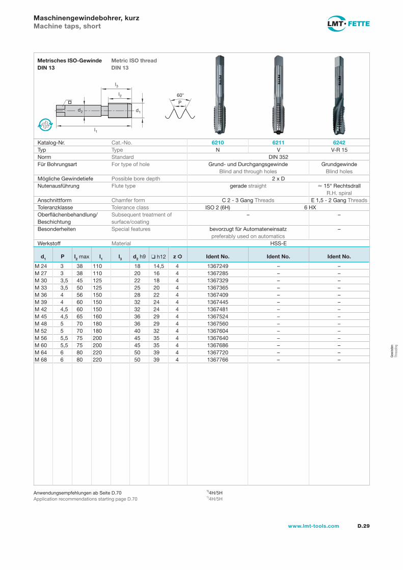
Maschinengewindebohrer, kurzMachine taps, short
Katalog-Nr. Cat.-No. 6210 6211 6242Typ Type NNorm Standard DIN 352Für Bohrungsart For type of hole Grund- und Durchgangsgewinde
Blind and through holesGrundgewinde
Blind holesMögliche Gewindetiefe Possible bore depth 2 x DNutenausführung Flute type gerade straight 15° Rechtsdrall
R.H. spiralAnschnittform Chamfer form C 2 - 3 Gang Threads E 1,5 - 2 Gang ThreadsToleranzklasse Tolerance class 6 HXOberflächenbehandlung/Beschichtung
Subsequent treatment of surface/coating
– –
Besonderheiten Special features bevorzugt für Automateneinsatz preferably used on automatics
–
Werkstoff Material HSS-E
V V-R 15
ISO 2 (6H)
d1 P l2 max l1 l3 d2 h9 h12 z Ident No. Ident No. Ident No.
M 24 3 38 110 18 14,5 4 1367249 – –M 27 3 38 110 20 16 4 1367285 – –M 30 3,5 45 125 22 18 4 1367329 – –M 33 3,5 50 125 25 20 4 1367365 – –M 36 4 56 150 28 22 4 1367409 – –M 39 4 60 150 32 24 4 1367445 – –M 42 4,5 60 150 32 24 4 1367481 – –M 45 4,5 65 160 36 29 4 1367524 – –M 48 5 70 180 36 29 4 1367560 – –M 52 5 70 180 40 32 4 1367604 – –M 56 5,5 75 200 45 35 4 1367640 – –M 60 5,5 75 200 45 35 4 1367686 – –M 64 6 80 220 50 39 4 1367720 – –M 68 6 80 220 50 39 4 1367766 – –
l1
d2
l2
d1
60
P
l3
D.30 www.lmt-tools.com
Metric ISO thread DIN 13
Metrisches ISO-Gewinde DIN 13
Anwendungsempfehlungen ab Seite D.70Application recommendations starting page D.70
Maschinengewindebohrer Markant®, kurz Machine taps Markant®, short
Katalog-Nr. Cat.-No. 6451 6451 CTyp Type NNorm Standard DIN 352Für Bohrungsart For type of hole Durchgangsgewinde Through holesMögliche Gewindetiefe Possible bore depth 3 x DNutenausführung Flute type gerade / Schälnut straight / Spiral pointedAnschnittform Chamfer form B 3,5 - 5 Gang ThreadsToleranzklasse Tolerance class ISO 2 (6H)Oberflächenbehandlung/Beschichtung
Subsequent treatment of surface/coating
– TiCN Plus
Besonderheiten Special features bevorzugt für Automateneinsatz preferably used on automaticsWerkstoff Material HSS-E
d1 P l2 max l1 l3 d2 h9 h12 z Ident No. Ident No.
mit verstärktem Zylinderschaft with reinforced straight shankM 2 0,4 8 36 2,8 2,1 3 1384916 1384920M 2,2 0,45 9 36 2,8 2,1 3 1384917 1384921M 2,3 0,4 9 36 2,8 2,1 3 1384934 1384922M 2,5 0,45 9 40 10 2,8 2,1 3 1384943 1384923M 2,6 0,45 9 40 10 2,8 2,1 3 1384952 1384924M 3 0,5 11 40 18 3,5 2,7 3 1384961 1384962M 3,5 0,6 12 45 20 4 3 3 1384918 1384925M 4 0,7 13 45 21 4,5 3,4 3 1384989 1384963M 5 0,8 14 50 25 6 4,9 3 1385005 1384964M 6 1 19 56 30 6 4,9 3 1385014 1384965
mit Überlaufschaft with standard straight shankM 7 1 19 56 6 4,9 3 1384919 1384926M 8 1,25 22 63 6 4,9 3 1385032 1384966M 10 1,5 24 70 7 5,5 4 1385041 1384967M 12 1,75 28 75 9 7 4 1385050 1384968M 14 2 30 80 11 9 4 1385069 1384927M 16 2 32 80 12 9 4 1385078 1384969M 18 2,5 34 95 14 11 4 1385087 1384928M 20 2,5 34 95 16 12 4 1385096 1384971
Gew
inde
n Th
read
ing
l1
d2
l2
d1
60
P
l3
D.31www.lmt-tools.com
Metric ISO thread DIN 13
Metrisches ISO-Gewinde DIN 13
Anwendungsempfehlungen ab Seite D.70Application recommendations starting page D.70
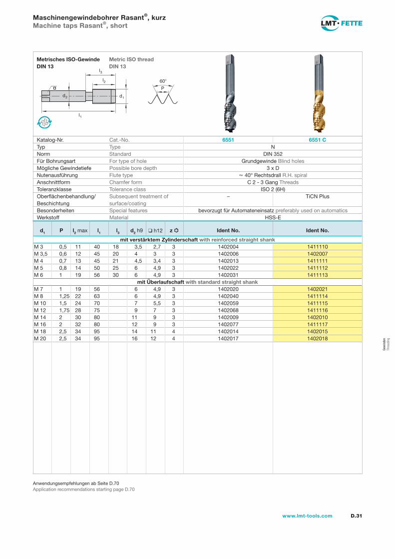
Maschinengewindebohrer Rasant®, kurzMachine taps Rasant®, short
Katalog-Nr. Cat.-No. 6551 6551 CTyp Type NNorm Standard DIN 352Für Bohrungsart For type of hole Grundgewinde Blind holesMögliche Gewindetiefe Possible bore depth 3 x DNutenausführung Flute type 40° Rechtsdrall R.H. spiralAnschnittform Chamfer form C 2 - 3 Gang ThreadsToleranzklasse Tolerance class ISO 2 (6H)Oberflächenbehandlung/Beschichtung
Subsequent treatment of surface/coating
– TiCN Plus
Besonderheiten Special features bevorzugt für Automateneinsatz preferably used on automaticsWerkstoff Material HSS-E
d1 P l2 max l1 l3 d2 h9 h12 z Ident No. Ident No.
mit verstärktem Zylinderschaft with reinforced straight shankM 3 0,5 11 40 18 3,5 2,7 3 1402004 1411110M 3,5 0,6 12 45 20 4 3 3 1402006 1402007M 4 0,7 13 45 21 4,5 3,4 3 1402013 1411111M 5 0,8 14 50 25 6 4,9 3 1402022 1411112M 6 1 19 56 30 6 4,9 3 1402031 1411113
mit Überlaufschaft with standard straight shankM 7 1 19 56 6 4,9 3 1402020 1402021M 8 1,25 22 63 6 4,9 3 1402040 1411114M 10 1,5 24 70 7 5,5 3 1402059 1411115M 12 1,75 28 75 9 7 3 1402068 1411116M 14 2 30 80 11 9 3 1402009 1402010M 16 2 32 80 12 9 3 1402077 1411117M 18 2,5 34 95 14 11 4 1402014 1402015M 20 2,5 34 95 16 12 4 1402017 1402018
l1
d2
l2
d
l3
d1
60
P
D.32 www.lmt-tools.com
Metric ISO thread DIN 13
Metrisches ISO-Gewinde DIN 13
Anwendungsempfehlungen ab Seite D.70Application recommendations starting page D.70
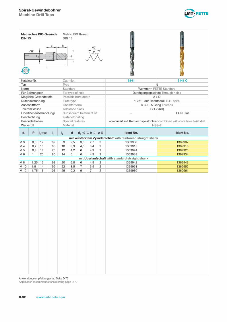
Spiral-GewindebohrerMachine Drill Taps
Katalog-Nr. Cat.-No. 6141 6141 CTyp Type NNorm Standard Werknorm FETTE StandardFür Bohrungsart For type of hole Durchgangsgewinde Through holesMögliche Gewindetiefe Possible bore depth 2 x DNutenausführung Flute type 25° - 30° Rechtsdrall R.H. spiralAnschnittform Chamfer form D 3,5 - 5 Gang ThreadsToleranzklasse Tolerance class ISO 2 (6H)Oberflächenbehandlung/Beschichtung
Subsequent treatment of surface/coating
– TiCN Plus
Besonderheiten Special features kombiniert mit Kernlochspiralbohrer combined with core hole twist drillWerkstoff Material HSS-E
d1 P l2 max l1 l3 d d2 h9 h12 z Ident No. Ident No.
mit verstärktem Zylinderschaft with reinforced straight shankM 3 0,5 12 62 9 2,5 3,5 2,7 2 1369906 1369907M 4 0,7 16 66 10 3,3 4,5 3,4 2 1369915 1369916M 5 0,8 18 75 12 4,2 6 4,9 2 1369924 1369925M 6 1 20 80 14 5 6 4,9 2 1369933 1369934
mit Überlaufschaft with standard straight shankM 8 1,25 12 93 20 6,8 6 4,9 2 1369942 1369943M 10 1,5 14 99 22 8,5 7 5,5 2 1369951 1369952M 12 1,75 16 106 25 10,2 9 7 2 1369960 1369961
Gew
inde
n Th
read
ing
l1
d2
l2
d1
60
P
l3
D.33www.lmt-tools.com
Metric ISO thread DIN 13
Metrisches ISO-Gewinde DIN 13
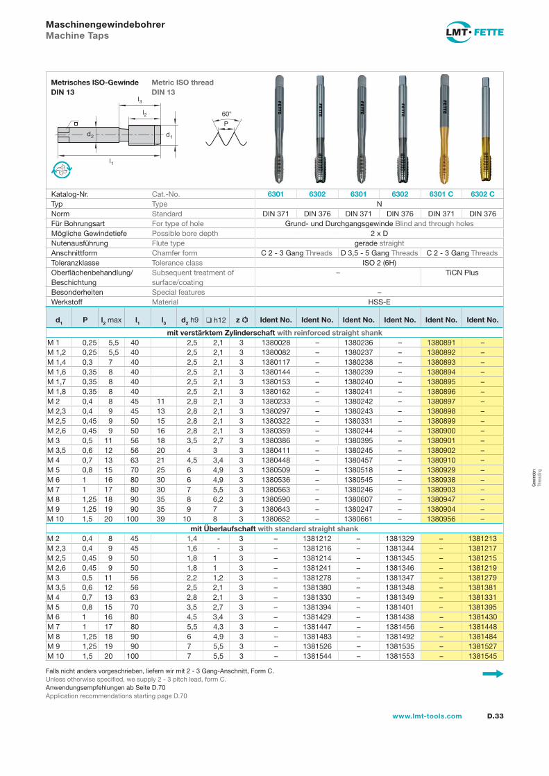
Falls nicht anders vorgeschrieben, liefern wir mit 2 - 3 Gang-Anschnitt, Form C.Unless otherwise specified, we supply 2 - 3 pitch lead, form C.Anwendungsempfehlungen ab Seite D.70Application recommendations starting page D.70
MaschinengewindebohrerMachine Taps
Katalog-Nr. Cat.-No. 6301 6302 6301 6302 6301 C 6302 CTyp Type NNorm Standard DIN 371 DIN 376 DIN 371 DIN 376 DIN 371 DIN 376Für Bohrungsart For type of hole Grund- und Durchgangsgewinde Blind and through holesMögliche Gewindetiefe Possible bore depth 2 x DNutenausführung Flute type gerade straightAnschnittform Chamfer form C 2 - 3 Gang Threads D 3,5 - 5 Gang Threads C 2 - 3 Gang ThreadsToleranzklasse Tolerance class ISO 2 (6H)Oberflächenbehandlung/Beschichtung
Subsequent treatment of surface/coating
– TiCN Plus
Besonderheiten Special features –Werkstoff Material HSS-E
d1 P l2 max l1 l3 d2 h9 h12 z Ident No. Ident No. Ident No. Ident No. Ident No. Ident No.
mit verstärktem Zylinderschaft with reinforced straight shankM 1 0,25 5,5 40 2,5 2,1 3 1380028 – 1380236 – 1380891 –M 1,2 0,25 5,5 40 2,5 2,1 3 1380082 – 1380237 – 1380892 –M 1,4 0,3 7 40 2,5 2,1 3 1380117 – 1380238 – 1380893 –M 1,6 0,35 8 40 2,5 2,1 3 1380144 – 1380239 – 1380894 –M 1,7 0,35 8 40 2,5 2,1 3 1380153 – 1380240 – 1380895 –M 1,8 0,35 8 40 2,5 2,1 3 1380162 – 1380241 – 1380896 –M 2 0,4 8 45 11 2,8 2,1 3 1380233 – 1380242 – 1380897 –M 2,3 0,4 9 45 13 2,8 2,1 3 1380297 – 1380243 – 1380898 –M 2,5 0,45 9 50 15 2,8 2,1 3 1380322 – 1380331 – 1380899 –M 2,6 0,45 9 50 16 2,8 2,1 3 1380359 – 1380244 – 1380900 –M 3 0,5 11 56 18 3,5 2,7 3 1380386 – 1380395 – 1380901 –M 3,5 0,6 12 56 20 4 3 3 1380411 – 1380245 – 1380902 –M 4 0,7 13 63 21 4,5 3,4 3 1380448 – 1380457 – 1380910 –M 5 0,8 15 70 25 6 4,9 3 1380509 – 1380518 – 1380929 –M 6 1 16 80 30 6 4,9 3 1380536 – 1380545 – 1380938 –M 7 1 17 80 30 7 5,5 3 1380563 – 1380246 – 1380903 –M 8 1,25 18 90 35 8 6,2 3 1380590 – 1380607 – 1380947 –M 9 1,25 19 90 35 9 7 3 1380643 – 1380247 – 1380904 –M 10 1,5 20 100 39 10 8 3 1380652 – 1380661 – 1380956 –
mit Überlaufschaft with standard straight shankM 2 0,4 8 45 1,4 - 3 – 1381212 – 1381329 – 1381213M 2,3 0,4 9 45 1,6 - 3 – 1381216 – 1381344 – 1381217M 2,5 0,45 9 50 1,8 1 3 – 1381214 – 1381345 – 1381215M 2,6 0,45 9 50 1,8 1 3 – 1381241 – 1381346 – 1381219M 3 0,5 11 56 2,2 1,2 3 – 1381278 – 1381347 – 1381279M 3,5 0,6 12 56 2,5 2,1 3 – 1381380 – 1381348 – 1381381M 4 0,7 13 63 2,8 2,1 3 – 1381330 – 1381349 – 1381331M 5 0,8 15 70 3,5 2,7 3 – 1381394 – 1381401 – 1381395M 6 1 16 80 4,5 3,4 3 – 1381429 – 1381438 – 1381430M 7 1 17 80 5,5 4,3 3 – 1381447 – 1381456 – 1381448M 8 1,25 18 90 6 4,9 3 – 1381483 – 1381492 – 1381484M 9 1,25 19 90 7 5,5 3 – 1381526 – 1381535 – 1381527M 10 1,5 20 100 7 5,5 3 – 1381544 – 1381553 – 1381545
l1
d2
l2
d1
60
P
l3
D.34 www.lmt-tools.com
Metric ISO thread DIN 13
Metrisches ISO-Gewinde DIN 13
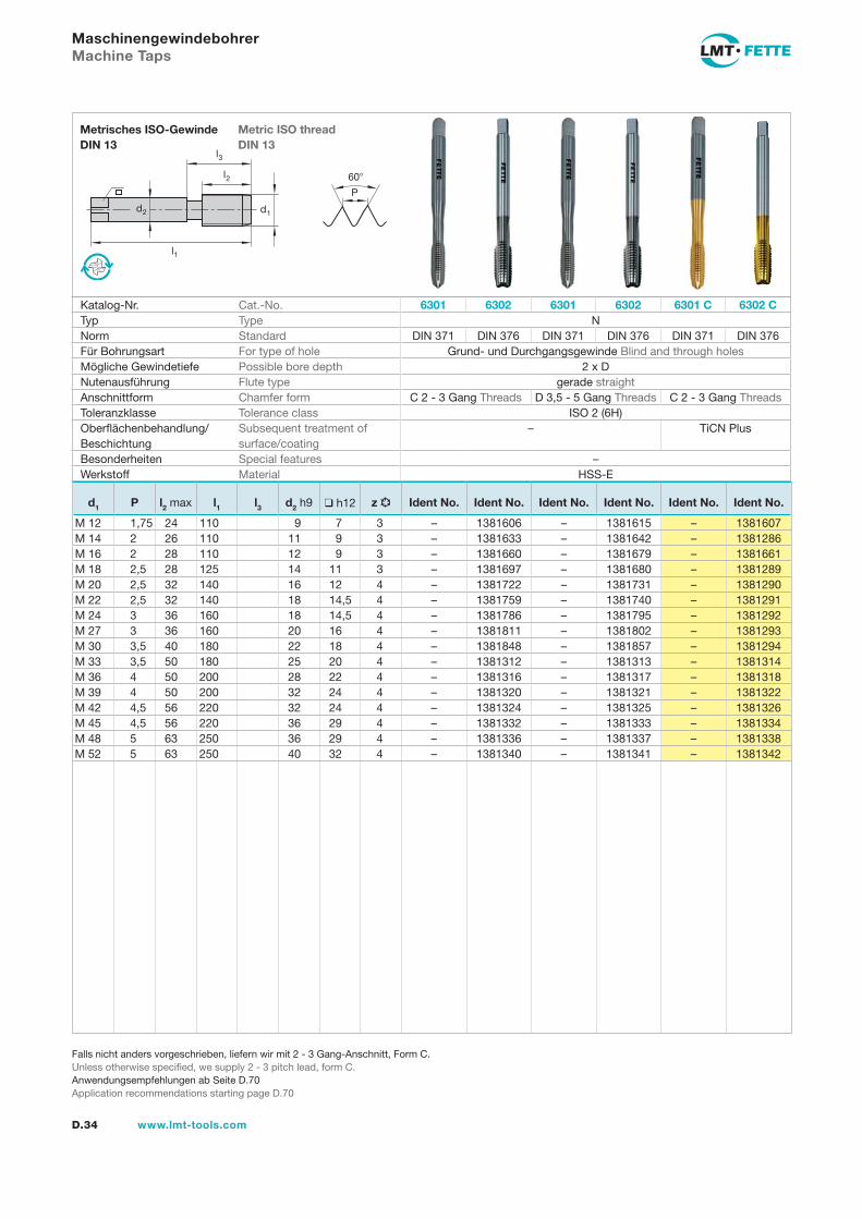
Falls nicht anders vorgeschrieben, liefern wir mit 2 - 3 Gang-Anschnitt, Form C.Unless otherwise specified, we supply 2 - 3 pitch lead, form C.Anwendungsempfehlungen ab Seite D.70Application recommendations starting page D.70
MaschinengewindebohrerMachine Taps
Katalog-Nr. Cat.-No. 6301 6302 6301 6302 6301 C 6302 CTyp Type NNorm Standard DIN 371 DIN 376 DIN 371 DIN 376 DIN 371 DIN 376Für Bohrungsart For type of hole Grund- und Durchgangsgewinde Blind and through holesMögliche Gewindetiefe Possible bore depth 2 x DNutenausführung Flute type gerade straightAnschnittform Chamfer form C 2 - 3 Gang Threads D 3,5 - 5 Gang Threads C 2 - 3 Gang ThreadsToleranzklasse Tolerance class ISO 2 (6H)Oberflächenbehandlung/Beschichtung
Subsequent treatment of surface/coating
– TiCN Plus
Besonderheiten Special features –Werkstoff Material HSS-E
d1 P l2 max l1 l3 d2 h9 h12 z Ident No. Ident No. Ident No. Ident No. Ident No. Ident No.
M 12 1,75 24 110 9 7 3 – 1381606 – 1381615 – 1381607M 14 2 26 110 11 9 3 – 1381633 – 1381642 – 1381286M 16 2 28 110 12 9 3 – 1381660 – 1381679 – 1381661M 18 2,5 28 125 14 11 3 – 1381697 – 1381680 – 1381289M 20 2,5 32 140 16 12 4 – 1381722 – 1381731 – 1381290M 22 2,5 32 140 18 14,5 4 – 1381759 – 1381740 – 1381291M 24 3 36 160 18 14,5 4 – 1381786 – 1381795 – 1381292M 27 3 36 160 20 16 4 – 1381811 – 1381802 – 1381293M 30 3,5 40 180 22 18 4 – 1381848 – 1381857 – 1381294M 33 3,5 50 180 25 20 4 – 1381312 – 1381313 – 1381314M 36 4 50 200 28 22 4 – 1381316 – 1381317 – 1381318M 39 4 50 200 32 24 4 – 1381320 – 1381321 – 1381322M 42 4,5 56 220 32 24 4 – 1381324 – 1381325 – 1381326M 45 4,5 56 220 36 29 4 – 1381332 – 1381333 – 1381334M 48 5 63 250 36 29 4 – 1381336 – 1381337 – 1381338M 52 5 63 250 40 32 4 – 1381340 – 1381341 – 1381342
Gew
inde
n Th
read
ing
l1
d2
l2
d1
60
P
l3
D.35www.lmt-tools.com
Metric ISO thread DIN 13
Metrisches ISO-Gewinde DIN 13
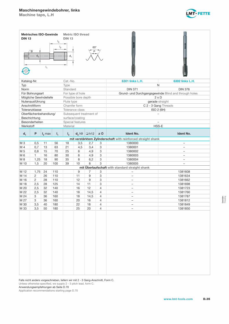
Falls nicht anders vorgeschrieben, liefern wir mit 2 - 3 Gang-Anschnitt, Form C.Unless otherwise specified, we supply 2 - 3 pitch lead, form C.Anwendungsempfehlungen ab Seite D.70Application recommendations starting page D.70
Maschinengewindebohrer, linksMachine taps, L.H
Katalog-Nr. Cat.-No. 6301 links L.H. 6302 links L.H.Typ Type NNorm Standard DIN 371 DIN 376Für Bohrungsart For type of hole Grund- und Durchgangsgewinde Blind and through holesMögliche Gewindetiefe Possible bore depth 2 x DNutenausführung Flute type gerade straightAnschnittform Chamfer form C 2 - 3 Gang ThreadsToleranzklasse Tolerance class ISO 2 (6H)Oberflächenbehandlung/Beschichtung
Subsequent treatment of surface/coating
–
Besonderheiten Special features –Werkstoff Material HSS-E
d1 P l2 max l1 l3 d2 h9 h12 z Ident No. Ident No.
mit verstärktem Zylinderschaft with reinforced straight shankM 3 0,5 11 56 18 3,5 2,7 3 1380000 –M 4 0,7 13 63 21 4,5 3,4 3 1380001 –M 5 0,8 15 70 25 6 4,9 3 1380002 –M 6 1 16 80 30 6 4,9 3 1380003 –M 8 1,25 18 90 35 8 6,2 3 1380004 –M 10 1,5 20 100 39 10 8 3 1380005 –
mit Überlaufschaft with standard straight shankM 12 1,75 24 110 9 7 3 – 1381608M 14 2 26 110 11 9 3 – 1381634M 16 2 28 110 12 9 3 – 1381662M 18 2,5 28 125 14 11 3 – 1381698M 20 2,5 32 140 16 12 4 – 1381723M 22 2,5 32 140 18 14,5 4 – 1381760M 24 3 36 160 18 14,5 4 – 1381787M 27 3 36 160 20 16 4 – 1381812M 30 3,5 40 180 22 18 4 – 1381849M 33 3,5 50 180 25 20 4 – 1381850
l1
d2
l2
d1
60
P
l3
D.36 www.lmt-tools.com
Metric ISO thread DIN 13
Metrisches ISO-Gewinde DIN 13
Anwendungsempfehlungen ab Seite D.70Application recommendations starting page D.70
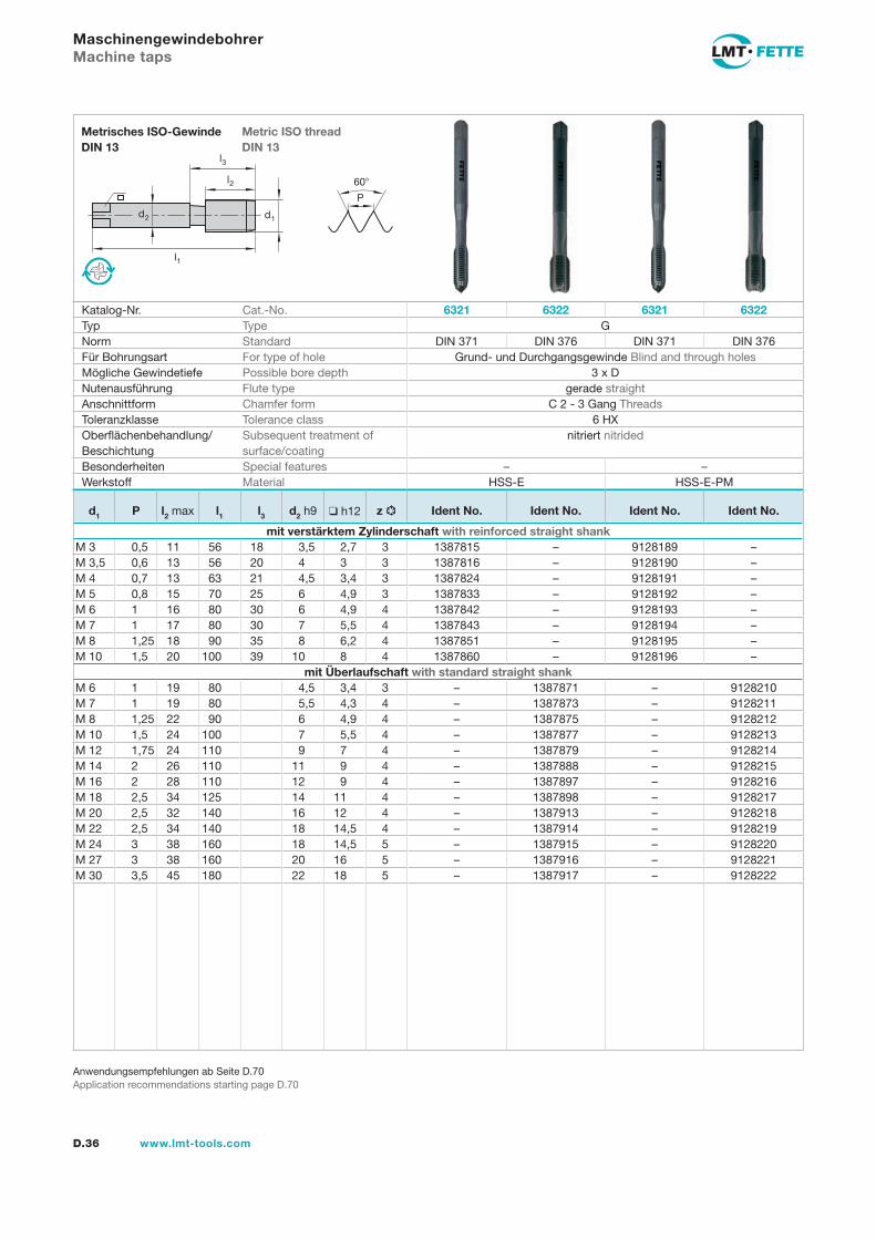
MaschinengewindebohrerMachine taps
Katalog-Nr. Cat.-No. 6321 6322 6321 6322Typ Type GNorm Standard DIN 371 DIN 376 DIN 371 DIN 376Für Bohrungsart For type of hole Grund- und Durchgangsgewinde Blind and through holesMögliche Gewindetiefe Possible bore depth 3 x DNutenausführung Flute type gerade straightAnschnittform Chamfer form C 2 - 3 Gang ThreadsToleranzklasse Tolerance class 6 HXOberflächenbehandlung/Beschichtung
Subsequent treatment of surface/coating
nitriert nitrided
Besonderheiten Special features – –Werkstoff Material HSS-E HSS-E-PM
d1 P l2 max l1 l3 d2 h9 h12 z Ident No. Ident No. Ident No. Ident No.
mit verstärktem Zylinderschaft with reinforced straight shankM 3 0,5 11 56 18 3,5 2,7 3 1387815 – 9128189 –M 3,5 0,6 13 56 20 4 3 3 1387816 – 9128190 –M 4 0,7 13 63 21 4,5 3,4 3 1387824 – 9128191 –M 5 0,8 15 70 25 6 4,9 3 1387833 – 9128192 –M 6 1 16 80 30 6 4,9 4 1387842 – 9128193 –M 7 1 17 80 30 7 5,5 4 1387843 – 9128194 –M 8 1,25 18 90 35 8 6,2 4 1387851 – 9128195 –M 10 1,5 20 100 39 10 8 4 1387860 – 9128196 –
mit Überlaufschaft with standard straight shankM 6 1 19 80 4,5 3,4 3 – 1387871 – 9128210M 7 1 19 80 5,5 4,3 4 – 1387873 – 9128211M 8 1,25 22 90 6 4,9 4 – 1387875 – 9128212M 10 1,5 24 100 7 5,5 4 – 1387877 – 9128213M 12 1,75 24 110 9 7 4 – 1387879 – 9128214M 14 2 26 110 11 9 4 – 1387888 – 9128215M 16 2 28 110 12 9 4 – 1387897 – 9128216M 18 2,5 34 125 14 11 4 – 1387898 – 9128217M 20 2,5 32 140 16 12 4 – 1387913 – 9128218M 22 2,5 34 140 18 14,5 4 – 1387914 – 9128219M 24 3 38 160 18 14,5 5 – 1387915 – 9128220M 27 3 38 160 20 16 5 – 1387916 – 9128221M 30 3,5 45 180 22 18 5 – 1387917 – 9128222
Gew
inde
n Th
read
ing
l1
d2
l2
d1
60
P
l3
D.37www.lmt-tools.com
Metric ISO thread DIN 13
Metrisches ISO-Gewinde DIN 13
Anwendungsempfehlungen ab Seite D.70Application recommendations starting page D.70
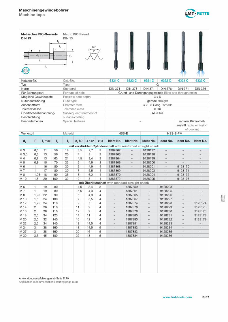
MaschinengewindebohrerMachine taps
Katalog-Nr. Cat.-No. 6321 C 6322 C 6321 C 6322 C 6321 C 6322 CTyp Type GNorm Standard DIN 371 DIN 376 DIN 371 DIN 376 DIN 371 DIN 376Für Bohrungsart For type of hole Grund- und Durchgangsgewinde Blind and through holesMögliche Gewindetiefe Possible bore depth 3 x DNutenausführung Flute type gerade straightAnschnittform Chamfer form C 2 - 3 Gang ThreadsToleranzklasse Tolerance class 6 HXOberflächenbehandlung/Beschichtung
Subsequent treatment of surface/coating
AL2Plus
Besonderheiten Special features – radialer Kühlmittel- austritt radial emission
of coolantWerkstoff Material HSS-E HSS-E-PM
d1 P l2 max l1 l3 d2 h9 h12 z Ident No. Ident No. Ident No. Ident No. Ident No. Ident No.
mit verstärktem Zylinderschaft with reinforced straight shankM 3 0,5 11 56 18 3,5 2,7 3 1387862 – 9128197 – – –M 3,5 0,6 13 56 20 4 3 3 1387863 – 9128198 – – –M 4 0,7 13 63 21 4,5 3,4 3 1387864 – 9128199 – – –M 5 0,8 15 70 25 6 4,9 3 1387866 – 9128200 – – –M 6 1 16 80 30 6 4,9 4 1387868 – 9128201 – 9128170 –M 7 1 17 80 30 7 5,5 4 1387869 – 9128203 – 9128171 –M 8 1,25 18 90 35 8 6,2 4 1387870 – 9128204 – 9128172 –M 10 1,5 20 100 39 10 8 4 1387872 – 9128205 – 9128173 –
mit Überlaufschaft with standard straight shankM 6 1 19 80 4,5 3,4 3 – 1387859 – 9128223 – –M 7 1 19 80 5,5 4,3 4 – 1387861 – 9128225 – –M 8 1,25 22 90 6 4,9 4 – 1387865 – 9128226 – –M 10 1,5 24 100 7 5,5 4 – 1387867 – 9128227 – –M 12 1,75 24 110 9 7 4 – 1387874 – 9128228 – 9128174M 14 2 26 110 11 9 4 – 1387876 – 9128229 – 9128175M 16 2 28 110 12 9 4 – 1387878 – 9128230 – 9128176M 18 2,5 34 125 14 11 4 – 1387885 – 9128231 – 9128178M 20 2,5 32 140 16 12 4 – 1387880 – 9128232 – 9128179M 22 2,5 34 140 18 14,5 4 – 1387881 – 9128233 – –M 24 3 38 160 18 14,5 5 – 1387882 – 9128234 – –M 27 3 38 160 20 16 5 – 1387883 – 9128235 – –M 30 3,5 45 180 22 18 5 – 1387884 – 9128236 – –
l1
d2
l2
d1
60
P
l3
D.38 www.lmt-tools.com
Metric ISO thread DIN 13
Metrisches ISO-Gewinde DIN 13
Anwendungsempfehlungen ab Seite D.70Application recommendations starting page D.70
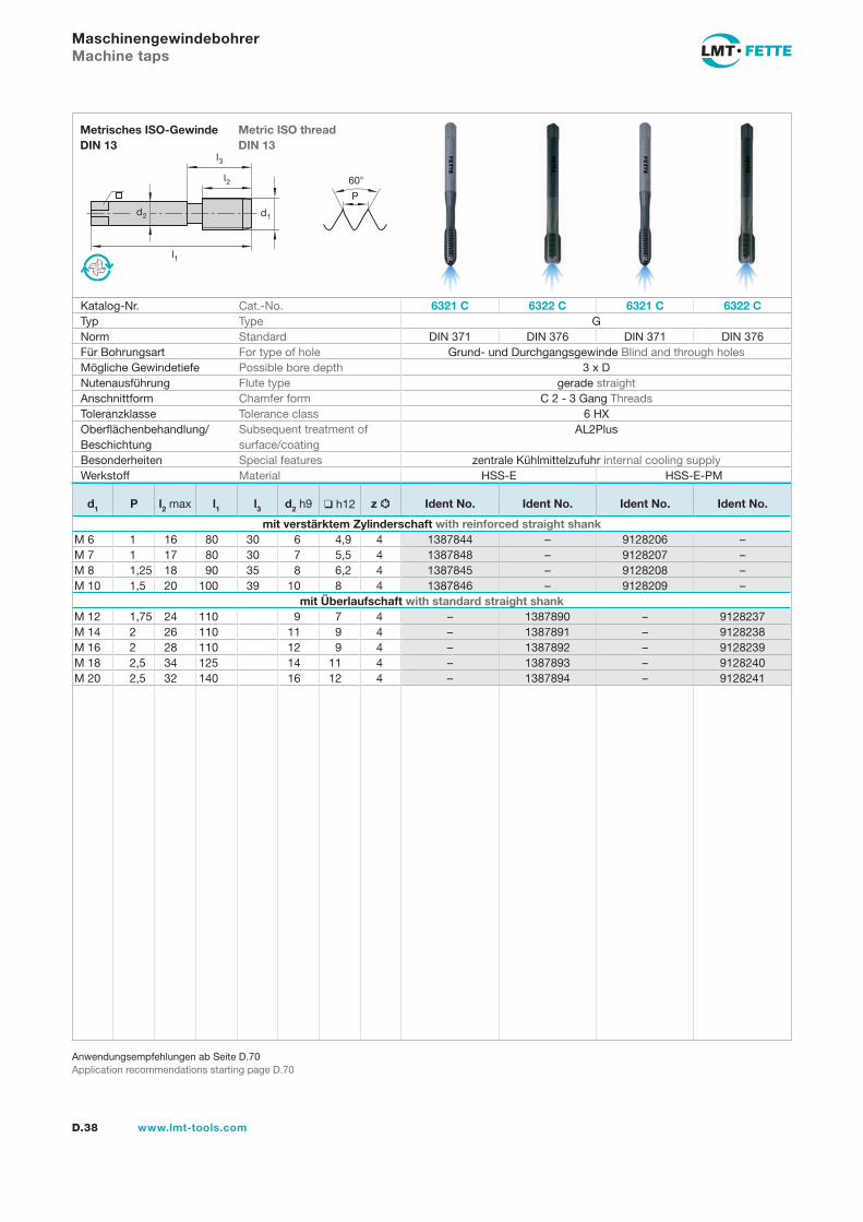
MaschinengewindebohrerMachine taps
Katalog-Nr. Cat.-No. 6321 C 6322 C 6321 C 6322 CTyp Type GNorm Standard DIN 371 DIN 376 DIN 371 DIN 376Für Bohrungsart For type of hole Grund- und Durchgangsgewinde Blind and through holesMögliche Gewindetiefe Possible bore depth 3 x DNutenausführung Flute type gerade straightAnschnittform Chamfer form C 2 - 3 Gang ThreadsToleranzklasse Tolerance class 6 HXOberflächenbehandlung/Beschichtung
Subsequent treatment of surface/coating
AL2Plus
Besonderheiten Special features zentrale Kühlmittelzufuhr internal cooling supplyWerkstoff Material HSS-E HSS-E-PM
d1 P l2 max l1 l3 d2 h9 h12 z Ident No. Ident No. Ident No. Ident No.
mit verstärktem Zylinderschaft with reinforced straight shankM 6 1 16 80 30 6 4,9 4 1387844 – 9128206 –M 7 1 17 80 30 7 5,5 4 1387848 – 9128207 –M 8 1,25 18 90 35 8 6,2 4 1387845 – 9128208 –M 10 1,5 20 100 39 10 8 4 1387846 – 9128209 –
mit Überlaufschaft with standard straight shankM 12 1,75 24 110 9 7 4 – 1387890 – 9128237M 14 2 26 110 11 9 4 – 1387891 – 9128238M 16 2 28 110 12 9 4 – 1387892 – 9128239M 18 2,5 34 125 14 11 4 – 1387893 – 9128240M 20 2,5 32 140 16 12 4 – 1387894 – 9128241
Gew
inde
n Th
read
ing
l1
d2
l2
d1
60
P
l3
D.39www.lmt-tools.com
Metric ISO threadDIN 13
Metrisches ISO-Gewinde DIN 13
Anwendungsempfehlungen ab Seite D.70Application recommendations starting page D.70
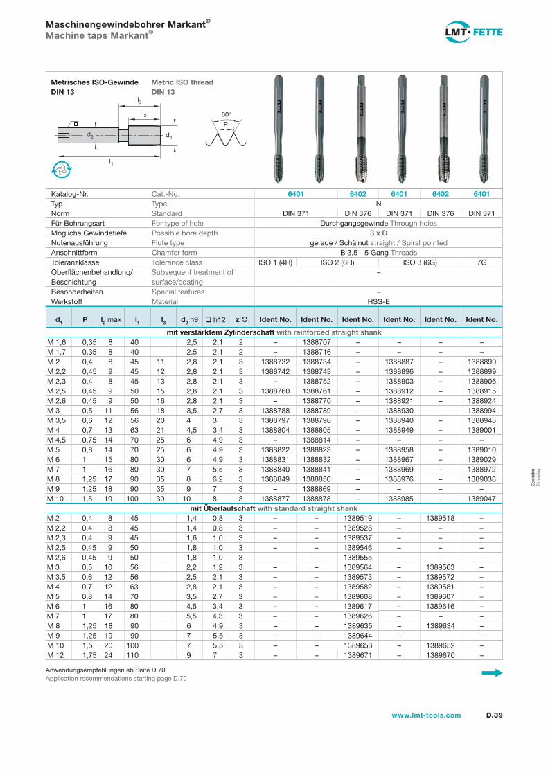
Maschinengewindebohrer Markant®
Machine taps Markant®
Katalog-Nr. Cat.-No. 6401 6402 6401 6402 6401Typ Type NNorm Standard DIN 371 DIN 376 DIN 371 DIN 376 DIN 371Für Bohrungsart For type of hole Durchgangsgewinde Through holesMögliche Gewindetiefe Possible bore depth 3 x DNutenausführung Flute type gerade / Schälnut straight / Spiral pointedAnschnittform Chamfer form B 3,5 - 5 Gang ThreadsToleranzklasse Tolerance class ISO 1 (4H) ISO 2 (6H) ISO 3 (6G) 7GOberflächenbehandlung/Beschichtung
Subsequent treatment of surface/coating
–
Besonderheiten Special features –Werkstoff Material HSS-E
d1 P l2 max l1 l3 d2 h9 h12 z Ident No. Ident No. Ident No. Ident No. Ident No. Ident No.
mit verstärktem Zylinderschaft with reinforced straight shankM 1,6 0,35 8 40 2,5 2,1 2 – 1388707 – – – –M 1,7 0,35 8 40 2,5 2,1 2 – 1388716 – – – –M 2 0,4 8 45 11 2,8 2,1 3 1388732 1388734 – 1388887 – 1388890M 2,2 0,45 9 45 12 2,8 2,1 3 1388742 1388743 – 1388896 – 1388899M 2,3 0,4 8 45 13 2,8 2,1 3 – 1388752 – 1388903 – 1388906M 2,5 0,45 9 50 15 2,8 2,1 3 1388760 1388761 – 1388912 – 1388915M 2,6 0,45 9 50 16 2,8 2,1 3 – 1388770 – 1388921 – 1388924M 3 0,5 11 56 18 3,5 2,7 3 1388788 1388789 – 1388930 – 1388994M 3,5 0,6 12 56 20 4 3 3 1388797 1388798 – 1388940 – 1388943M 4 0,7 13 63 21 4,5 3,4 3 1388804 1388805 – 1388949 – 1389001M 4,5 0,75 14 70 25 6 4,9 3 – 1388814 – – – –M 5 0,8 14 70 25 6 4,9 3 1388822 1388823 – 1388958 – 1389010M 6 1 15 80 30 6 4,9 3 1388831 1388832 – 1388967 – 1389029M 7 1 16 80 30 7 5,5 3 1388840 1388841 – 1388969 – 1388972M 8 1,25 17 90 35 8 6,2 3 1388849 1388850 – 1388976 – 1389038M 9 1,25 18 90 35 9 7 3 – 1388869 – – – –M 10 1,5 19 100 39 10 8 3 1388877 1388878 – 1388985 – 1389047
mit Überlaufschaft with standard straight shankM 2 0,4 8 45 1,4 0,8 3 – – 1389519 – 1389518 –M 2,2 0,4 8 45 1,4 0,8 3 – – 1389528 – – –M 2,3 0,4 9 45 1,6 1,0 3 – – 1389537 – – –M 2,5 0,45 9 50 1,8 1,0 3 – – 1389546 – – –M 2,6 0,45 9 50 1,8 1,0 3 – – 1389555 – – –M 3 0,5 10 56 2,2 1,2 3 – – 1389564 – 1389563 –M 3,5 0,6 12 56 2,5 2,1 3 – – 1389573 – 1389572 –M 4 0,7 12 63 2,8 2,1 3 – – 1389582 – 1389581 –M 5 0,8 14 70 3,5 2,7 3 – – 1389608 – 1389607 –M 6 1 16 80 4,5 3,4 3 – – 1389617 – 1389616 –M 7 1 17 80 5,5 4,3 3 – – 1389626 – – –M 8 1,25 18 90 6 4,9 3 – – 1389635 – 1389634 –M 9 1,25 19 90 7 5,5 3 – – 1389644 – – –M 10 1,5 20 100 7 5,5 3 – – 1389653 – 1389652 –M 12 1,75 24 110 9 7 3 – – 1389671 – 1389670 –
l1
d2
l2
d1
60
P
l3
D.40 www.lmt-tools.com
Metric ISO thread DIN 13
Metrisches ISO-Gewinde DIN 13
Anwendungsempfehlungen ab Seite D.70Application recommendations starting page D.70
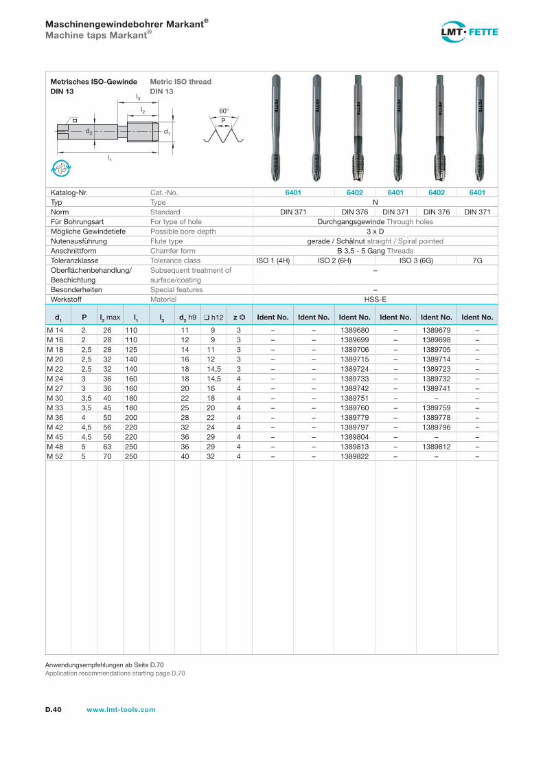
Maschinengewindebohrer Markant®
Machine taps Markant®
Katalog-Nr. Cat.-No. 6401 6402 6401 6402 6401Typ Type NNorm Standard DIN 371 DIN 376 DIN 371 DIN 376 DIN 371Für Bohrungsart For type of hole Durchgangsgewinde Through holesMögliche Gewindetiefe Possible bore depth 3 x DNutenausführung Flute type gerade / Schälnut straight / Spiral pointedAnschnittform Chamfer form B 3,5 - 5 Gang ThreadsToleranzklasse Tolerance class ISO 1 (4H) ISO 2 (6H) ISO 3 (6G) 7GOberflächenbehandlung/Beschichtung
Subsequent treatment of surface/coating
–
Besonderheiten Special features –Werkstoff Material HSS-E
d1 P l2 max l1 l3 d2 h9 h12 z Ident No. Ident No. Ident No. Ident No. Ident No. Ident No.
M 14 2 26 110 11 9 3 – – 1389680 – 1389679 –M 16 2 28 110 12 9 3 – – 1389699 – 1389698 –M 18 2,5 28 125 14 11 3 – – 1389706 – 1389705 –M 20 2,5 32 140 16 12 3 – – 1389715 – 1389714 –M 22 2,5 32 140 18 14,5 3 – – 1389724 – 1389723 –M 24 3 36 160 18 14,5 4 – – 1389733 – 1389732 –M 27 3 36 160 20 16 4 – – 1389742 – 1389741 –M 30 3,5 40 180 22 18 4 – – 1389751 – – –M 33 3,5 45 180 25 20 4 – – 1389760 – 1389759 –M 36 4 50 200 28 22 4 – – 1389779 – 1389778 –M 42 4,5 56 220 32 24 4 – – 1389797 – 1389796 –M 45 4,5 56 220 36 29 4 – – 1389804 – – –M 48 5 63 250 36 29 4 – – 1389813 – 1389812 –M 52 5 70 250 40 32 4 – – 1389822 – – –
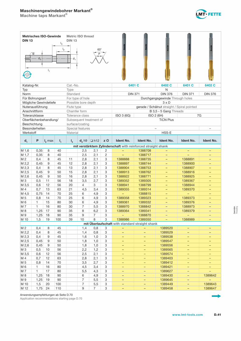
Gew
inde
n Th
read
ing
l1
d2
l2
d1
60
P
l3
D.41www.lmt-tools.com
Metric ISO thread DIN 13
Metrisches ISO-Gewinde DIN 13
Anwendungsempfehlungen ab Seite D.70Application recommendations starting page D.70
Maschinengewindebohrer Markant®
Machine taps Markant®
Katalog-Nr. Cat.-No. 6401 C 6402 C 6401 C 6402 CTyp Type NNorm Standard DIN 371 DIN 376 DIN 371 DIN 376Für Bohrungsart For type of hole Durchgangsgewinde Through holesMögliche Gewindetiefe Possible bore depth 3 x DNutenausführung Flute type gerade / Schälnut straight / Spiral pointedAnschnittform Chamfer form B 3,5 - 5 Gang ThreadsToleranzklasse Tolerance class ISO 3 (6G) ISO 2 (6H) 7GOberflächenbehandlung/Beschichtung
Subsequent treatment of surface/coating
TiCN Plus
Besonderheiten Special features – –Werkstoff Material HSS-E
d1 P l2 max l1 l3 d2 h9 h12 z Ident No. Ident No. Ident No. Ident No. Ident No.
mit verstärktem Zylinderschaft with reinforced straight shankM 1,6 0,35 8 40 2,5 2,1 2 – 1388708 – – –M 1,7 0,35 8 40 2,5 2,1 2 – 1388717 – – –M 2 0,4 8 45 11 2,8 2,1 3 1388888 1388735 – 1388891 –M 2,2 0,45 9 45 12 2,8 2,1 3 1388897 1388744 – 1388900 –M 2,3 0,4 8 45 13 2,8 2,1 3 1388904 1388753 – 1388907 –M 2,5 0,45 9 50 15 2,8 2,1 3 1388913 1388762 – 1388916 –M 2,6 0,45 9 50 16 2,8 2,1 3 1388922 1388771 – 1388925 –M 3 0,5 11 56 18 3,5 2,7 3 1389352 1389305 – 1389367 –M 3,5 0,6 12 56 20 4 3 3 1388941 1388799 – 1388944 –M 4 0,7 13 63 21 4,5 3,4 3 1389355 1389314 – 1389370 –M 4,5 0,75 14 70 25 6 4,9 3 – 1388815 – – –M 5 0,8 14 70 25 6 4,9 3 1389358 1389323 – 1389373 –M 6 1 15 80 30 6 4,9 3 1389361 1389332 – 1389376 –M 7 1 16 80 30 7 5,5 3 1388970 1388842 – 1388973 –M 8 1,25 17 90 35 8 6,2 3 1389364 1389341 – 1389379 –M 9 1,25 18 90 35 9 7 3 – 1388870 – – –M 10 1,5 19 100 39 10 8 3 1388986 1389350 – 1388989 –
mit Überlaufschaft with standard straight shankM 2 0,4 8 45 1,4 0,8 3 – – 1389520 – –M 2,2 0,4 8 45 1,4 0,8 3 – – 1389529 – –M 2,3 0,4 9 45 1,6 1,0 3 – – 1389538 – –M 2,5 0,45 9 50 1,8 1,0 3 – – 1389547 – –M 2,6 0,45 9 50 1,8 1,0 3 – – 1389556 – –M 3 0,5 10 56 2,2 1,2 3 – – 1389565 – –M 3,5 0,6 12 56 2,5 2,1 3 – – 1389574 – –M 4 0,7 12 63 2,8 2,1 3 – – 1389403 – –M 5 0,8 14 70 3,5 2,7 3 – – 1389412 – –M 6 1 16 80 4,5 3,4 3 – – 1389421 – –M 7 1 17 80 5,5 4,3 3 – – 1389627 – –M 8 1,25 18 90 6 4,9 3 – – 1389430 – 1389642M 9 1,25 19 90 7 5,5 3 – – 1389645 – –M 10 1,5 20 100 7 5,5 3 – – 1389449 – 1389643M 12 1,75 24 110 9 7 3 – – 1389458 – 1389647
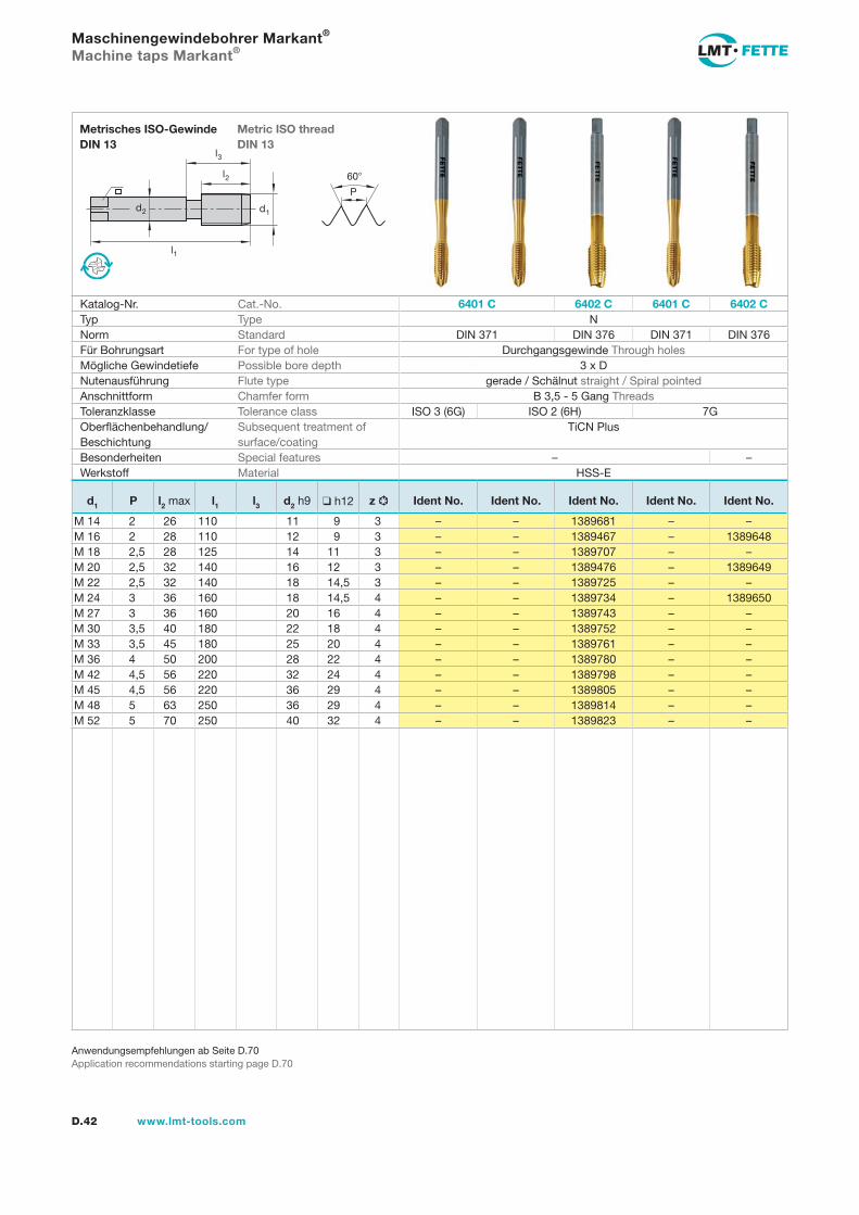
l1
d2
l2
d1
60
P
l3
D.42 www.lmt-tools.com
Metric ISO thread DIN 13
Metrisches ISO-Gewinde DIN 13
Anwendungsempfehlungen ab Seite D.70Application recommendations starting page D.70
Maschinengewindebohrer Markant®
Machine taps Markant®
Katalog-Nr. Cat.-No. 6401 C 6402 C 6401 C 6402 CTyp Type NNorm Standard DIN 371 DIN 376 DIN 371 DIN 376Für Bohrungsart For type of hole Durchgangsgewinde Through holesMögliche Gewindetiefe Possible bore depth 3 x DNutenausführung Flute type gerade / Schälnut straight / Spiral pointedAnschnittform Chamfer form B 3,5 - 5 Gang ThreadsToleranzklasse Tolerance class ISO 3 (6G) ISO 2 (6H) 7GOberflächenbehandlung/Beschichtung
Subsequent treatment of surface/coating
TiCN Plus
Besonderheiten Special features – –Werkstoff Material HSS-E
d1 P l2 max l1 l3 d2 h9 h12 z Ident No. Ident No. Ident No. Ident No. Ident No.
M 14 2 26 110 11 9 3 – – 1389681 – –M 16 2 28 110 12 9 3 – – 1389467 – 1389648M 18 2,5 28 125 14 11 3 – – 1389707 – –M 20 2,5 32 140 16 12 3 – – 1389476 – 1389649M 22 2,5 32 140 18 14,5 3 – – 1389725 – –M 24 3 36 160 18 14,5 4 – – 1389734 – 1389650M 27 3 36 160 20 16 4 – – 1389743 – –M 30 3,5 40 180 22 18 4 – – 1389752 – –M 33 3,5 45 180 25 20 4 – – 1389761 – –M 36 4 50 200 28 22 4 – – 1389780 – –M 42 4,5 56 220 32 24 4 – – 1389798 – –M 45 4,5 56 220 36 29 4 – – 1389805 – –M 48 5 63 250 36 29 4 – – 1389814 – –M 52 5 70 250 40 32 4 – – 1389823 – –
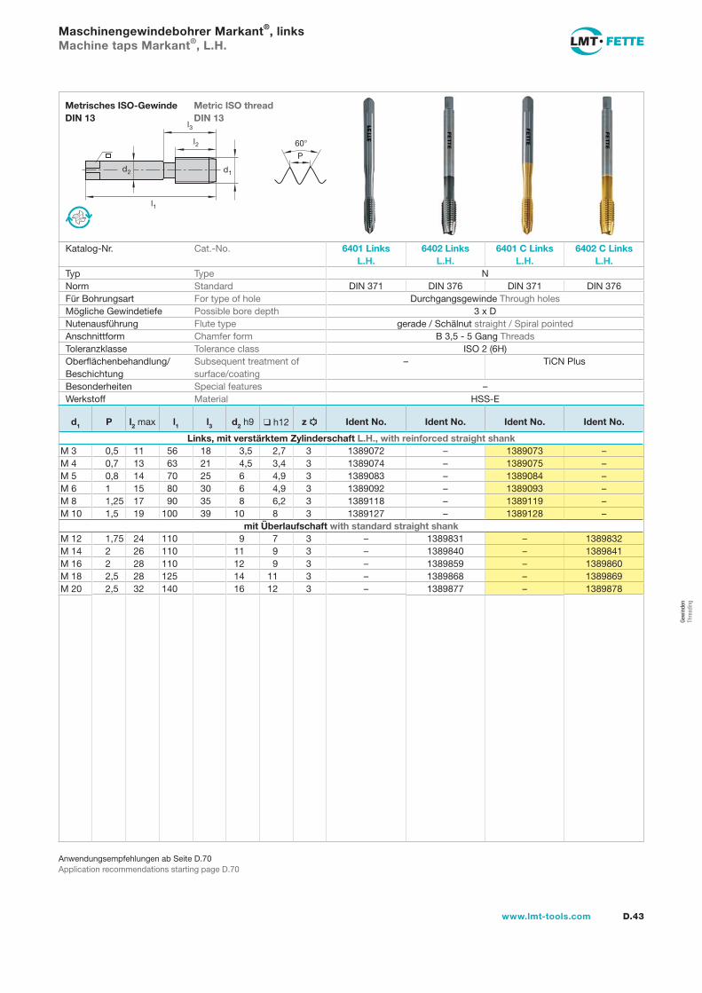
Gew
inde
n Th
read
ing
l1
d2
l2
d1
60
P
l3
D.43www.lmt-tools.com
Metric ISO thread DIN 13
Metrisches ISO-Gewinde DIN 13
Anwendungsempfehlungen ab Seite D.70Application recommendations starting page D.70
Maschinengewindebohrer Markant®, linksMachine taps Markant®, L.H.
Katalog-Nr. Cat.-No. 6401 Links L.H.
6402 Links L.H.
6401 C Links L.H.
6402 C Links L.H.
Typ Type NNorm Standard DIN 371 DIN 376 DIN 371 DIN 376Für Bohrungsart For type of hole Durchgangsgewinde Through holesMögliche Gewindetiefe Possible bore depth 3 x DNutenausführung Flute type gerade / Schälnut straight / Spiral pointedAnschnittform Chamfer form B 3,5 - 5 Gang ThreadsToleranzklasse Tolerance class ISO 2 (6H)Oberflächenbehandlung/Beschichtung
Subsequent treatment of surface/coating
– TiCN Plus
Besonderheiten Special features –Werkstoff Material HSS-E
d1 P l2 max l1 l3 d2 h9 h12 z Ident No. Ident No. Ident No. Ident No.
Links, mit verstärktem Zylinderschaft L.H., with reinforced straight shankM 3 0,5 11 56 18 3,5 2,7 3 1389072 – 1389073 –M 4 0,7 13 63 21 4,5 3,4 3 1389074 – 1389075 –M 5 0,8 14 70 25 6 4,9 3 1389083 – 1389084 –M 6 1 15 80 30 6 4,9 3 1389092 – 1389093 –M 8 1,25 17 90 35 8 6,2 3 1389118 – 1389119 –M 10 1,5 19 100 39 10 8 3 1389127 – 1389128 –
mit Überlaufschaft with standard straight shankM 12 1,75 24 110 9 7 3 – 1389831 – 1389832M 14 2 26 110 11 9 3 – 1389840 – 1389841M 16 2 28 110 12 9 3 – 1389859 – 1389860M 18 2,5 28 125 14 11 3 – 1389868 – 1389869M 20 2,5 32 140 16 12 3 – 1389877 – 1389878
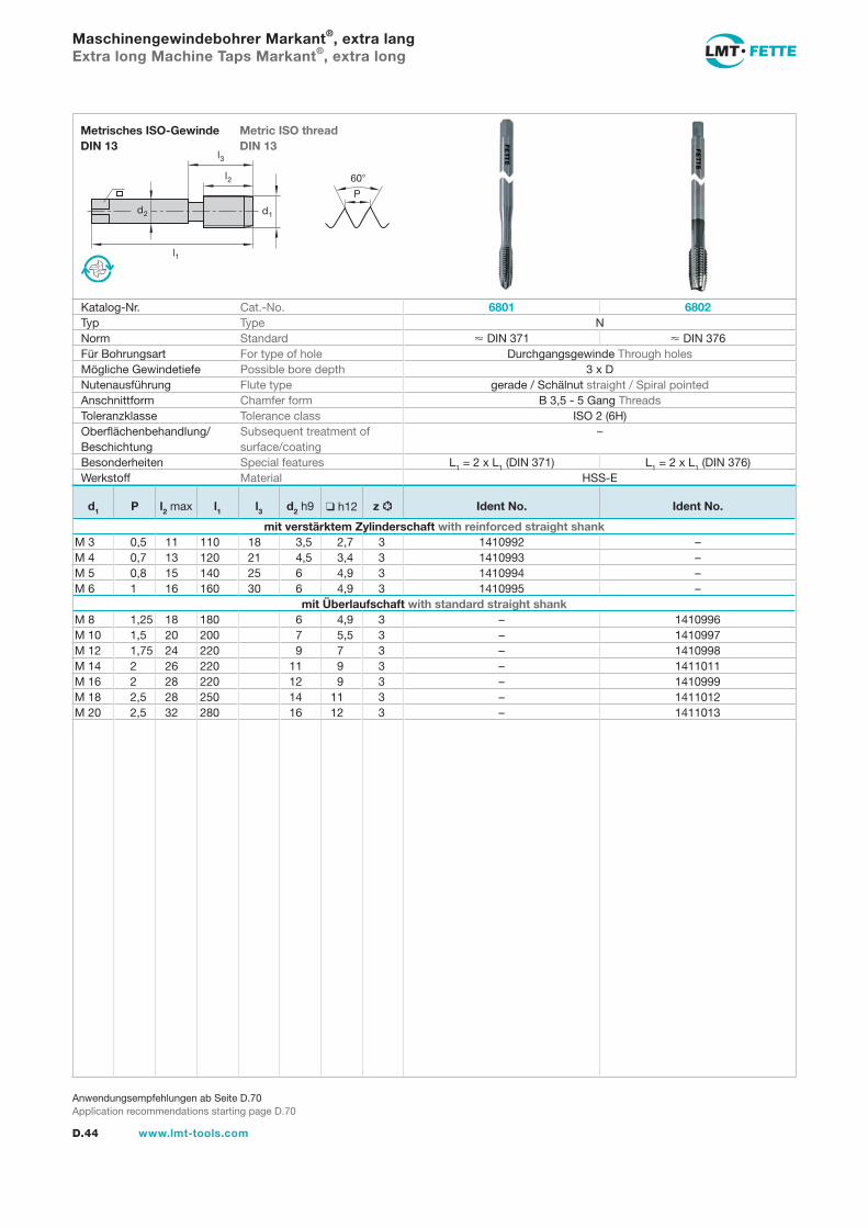
l1
d2
l2
d1
60
P
l3
D.44 www.lmt-tools.com
Metric ISO thread DIN 13
Metrisches ISO-Gewinde DIN 13
Anwendungsempfehlungen ab Seite D.70Application recommendations starting page D.70
Maschinengewindebohrer Markant®, extra langExtra long Machine Taps Markant®, extra long
Katalog-Nr. Cat.-No. 6801 6802Typ Type NNorm Standard DIN 371 DIN 376Für Bohrungsart For type of hole Durchgangsgewinde Through holesMögliche Gewindetiefe Possible bore depth 3 x DNutenausführung Flute type gerade / Schälnut straight / Spiral pointedAnschnittform Chamfer form B 3,5 - 5 Gang ThreadsToleranzklasse Tolerance class ISO 2 (6H)Oberflächenbehandlung/Beschichtung
Subsequent treatment of surface/coating
–
Besonderheiten Special features L1 = 2 x L1 (DIN 371) L1 = 2 x L1 (DIN 376)Werkstoff Material HSS-E
d1 P l2 max l1 l3 d2 h9 h12 z Ident No. Ident No.
mit verstärktem Zylinderschaft with reinforced straight shankM 3 0,5 11 110 18 3,5 2,7 3 1410992 –M 4 0,7 13 120 21 4,5 3,4 3 1410993 –M 5 0,8 15 140 25 6 4,9 3 1410994 –M 6 1 16 160 30 6 4,9 3 1410995 –
mit Überlaufschaft with standard straight shankM 8 1,25 18 180 6 4,9 3 – 1410996M 10 1,5 20 200 7 5,5 3 – 1410997M 12 1,75 24 220 9 7 3 – 1410998M 14 2 26 220 11 9 3 – 1411011M 16 2 28 220 12 9 3 – 1410999M 18 2,5 28 250 14 11 3 – 1411012M 20 2,5 32 280 16 12 3 – 1411013
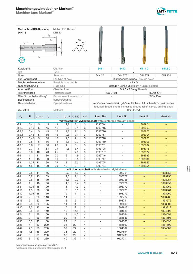
Gew
inde
n Th
read
ing
l1
d2
l2
d1
60
P
l3
D.45www.lmt-tools.com
Metric ISO thread DIN 13
Metrisches ISO-Gewinde DIN 13
Anwendungsempfehlungen ab Seite D.70Application recommendations starting page D.70
Maschinengewindebohrer Markant®
Machine taps Markant®
Katalog-Nr. Cat.-No. 6411 6412 6411 C 6412 CTyp Type VNorm Standard DIN 371 DIN 376 DIN 371 DIN 376Für Bohrungsart For type of hole Durchgangsgewinde Through holesMögliche Gewindetiefe Possible bore depth > 3 x DNutenausführung Flute type gerade / Schälnut straight / Spiral pointedAnschnittform Chamfer form B 3,5 - 5 Gang ThreadsToleranzklasse Tolerance class ISO 2 (6H) ISO 2 (6H)Oberflächenbehandlung/Beschichtung
Subsequent treatment of surface/coating
– TiCN Plus
Besonderheiten Special features verkürztes Gewindeteil, größerer Hinterschliff, schmale Schneidstollenreduced thread length, increased ground relief, narrow cutting lands
Werkstoff Material HSS-E-PM
d1 P l2 max l1 l3 d2 h9 h12 z Ident No. Ident No. Ident No. Ident No.
mit verstärktem Zylinderschaft with reinforced straight shankM 2 0,4 5 45 11 2,8 2,1 3 1393714 – 1393901 –M 2,2 0,45 5 45 12 2,8 2,1 3 1393715 – 1393902 –M 2,3 0,4 5 45 13 2,8 2,1 3 1393716 – 1393903 –M 2,5 0,45 5 50 15 2,8 2,1 3 1393717 – 1393904 –M 2,6 0,45 5 50 16 2,8 2,1 3 1393718 – 1393905 –M 3 0,5 6 56 18 3,5 2,7 3 1393719 – 1393906 –M 3,5 0,6 7 56 20 4 3 3 1393731 – 1393907 –M 4 0,7 8 63 21 4,5 3,4 3 1393728 – 1393915 –M 5 0,8 10 70 25 6 4,9 3 1393737 – 1393924 –M 6 1 11 80 30 6 4,9 3 1393746 – 1393933 –M 7 1 13 80 30 7 5,5 3 1393747 – 1393934 –M 8 1,25 13 90 35 8 6,2 3 1393755 – 1393942 –M 10 1,5 15 100 39 10 8 3 1393764 – 1393951 –
mit Überlaufschaft with standard straight shankM 3 0,5 11 56 2,2 1,2 3 – 1393751 – 1393953M 4 0,7 13 63 2,8 2,1 3 – 1393752 – 1393955M 5 0,8 15 70 3,5 2,7 3 – 1393768 – 1393957M 6 1 16 80 4,5 3,4 3 – 1393769 – 1393959M 8 1,25 18 90 6 4,9 3 – 1393770 – 1393962M 10 1,5 20 100 7 5,5 3 – 1393771 – 1393964M 12 1,75 18 110 9 7 3 – 1393773 – 1393960M 14 2 20 110 11 9 3 – 1393782 – 1393785M 16 2 22 110 12 9 3 – 1393791 – 1393979M 18 2,5 22 125 14 11 3 – 1393808 – 1393809M 20 2,5 25 140 16 12 3 – 1393817 – 1393818M 22 2,5 34 140 18 14,5 3 – 1384583 – 1394593M 24 3 36 160 18 14,5 4 – 1384584 – 1384594M 27 3 36 160 20 16 4 – 1384586 – 1384596M 30 3,5 40 180 22 18 4 – 1384588 – 1384598M 36 4 50 200 28 22 4 – 1384590 – 1384600M 42 4,5 56 200 32 24 4 – 1384592 – 1384602M 45 4,5 56 220 36 29 4 – 9127694 – –M 48 5 63 250 36 29 4 – 9127706 – –M 52 5 63 250 40 32 4 – 9127711 – –
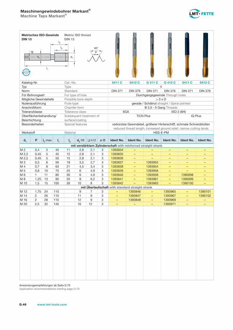
l1
d2
l2
d1
60
P
l3
D.46 www.lmt-tools.com
Metric ISO thread DIN 13
Metrisches ISO-Gewinde DIN 13
Anwendungsempfehlungen ab Seite D.70Application recommendations starting page D.70
Maschinengewindebohrer Markant®
Machine Taps Markant®
Katalog-Nr. Cat.-No. 6411 C 6412 C G 411 C G 412 C 6411 C 6412 CTyp Type VNorm Standard DIN 371 DIN 376 DIN 371 DIN 376Für Bohrungsart For type of hole Durchgangsgewinde Through holesMögliche Gewindetiefe Possible bore depth > 3 x DNutenausführung Flute type gerade / Schälnut straight / Spiral pointedAnschnittform Chamfer form B 3,5 - 5 Gang ThreadsToleranzklasse Tolerance class 6GX ISO 2 (6H)Oberflächenbehandlung/Beschichtung
Subsequent treatment of surface/coating
TiCN Plus IQ Plus
Besonderheiten Special features verkürztes Gewindeteil, größerer Hinterschliff, schmale Schneidstollen reduced thread length, increased ground relief, narrow cutting lands
Werkstoff Material HSS-E-PM
d1 P l2 max l1 l3 d2 h9 h12 z Ident No. Ident No. Ident No. Ident No. Ident No. Ident No.
mit verstärktem Zylinderschaft with reinforced straight shankM 2 0,4 5 45 11 2,8 2,1 3 1393834 – – – – –M 2,2 0,45 5 45 12 2,8 2,1 3 1393835 – – – – –M 2,5 0,45 5 50 15 2,8 2,1 3 1393836 – – – – –M 3 0,5 6 56 18 3,5 2,7 3 1393837 – 1393952 – – –M 4 0,7 8 63 21 4,5 3,4 3 1393838 – 1393954 – – –M 5 0,8 10 70 25 6 4,9 3 1393839 – 1393956 – – –M 6 1 11 80 30 6 4,9 3 1393840 – 1393958 – 1390098 –M 8 1,25 13 90 35 8 6,2 3 1393841 – 1393961 – 1390099 –M 10 1,5 15 100 39 10 8 3 1393842 – 1393963 – 1390100 –
mit Überlaufschaft with standard straight shankM 12 1,75 24 110 9 7 3 – 1393846 – 1393965 – 1390101M 14 2 26 110 11 9 3 – 1393847 – 1393967 – 1390102M 16 2 28 110 12 9 3 – 1393848 – 1393969 – –M 20 2,5 32 140 16 12 3 – – – 1393971 – –
DIN 371 DIN 376
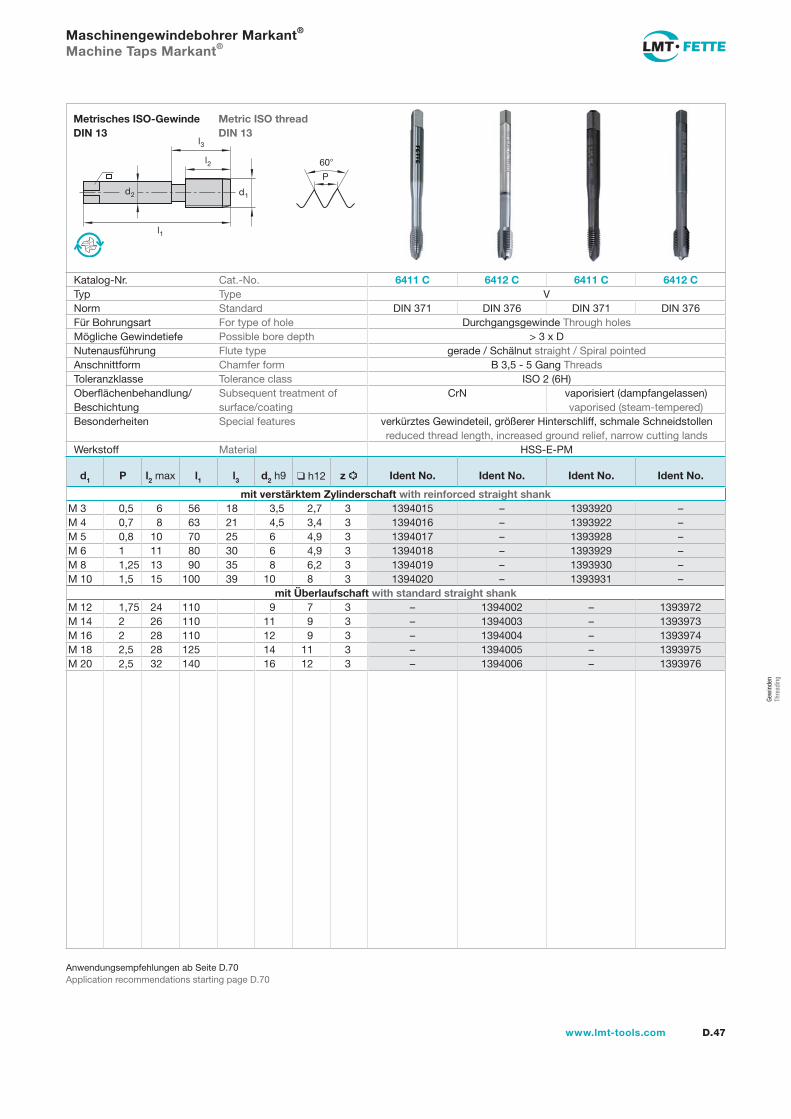
Gew
inde
n Th
read
ing
l1
d2
l2
d1
60
P
l3
D.47www.lmt-tools.com
Metric ISO thread DIN 13
Metrisches ISO-Gewinde DIN 13
Anwendungsempfehlungen ab Seite D.70Application recommendations starting page D.70
Maschinengewindebohrer Markant®
Machine Taps Markant®
Katalog-Nr. Cat.-No. 6411 C 6412 C 6411 C 6412 CTyp Type VNorm Standard DIN 371 DIN 376 DIN 371 DIN 376Für Bohrungsart For type of hole Durchgangsgewinde Through holesMögliche Gewindetiefe Possible bore depth > 3 x DNutenausführung Flute type gerade / Schälnut straight / Spiral pointedAnschnittform Chamfer form B 3,5 - 5 Gang ThreadsToleranzklasse Tolerance class ISO 2 (6H)Oberflächenbehandlung/Beschichtung
Subsequent treatment of surface/coating
CrN vaporisiert (dampfangelassen) vaporised (steam-tempered)
Besonderheiten Special features verkürztes Gewindeteil, größerer Hinterschliff, schmale Schneidstollen reduced thread length, increased ground relief, narrow cutting lands
Werkstoff Material HSS-E-PM
d1 P l2 max l1 l3 d2 h9 h12 z Ident No. Ident No. Ident No. Ident No.
mit verstärktem Zylinderschaft with reinforced straight shankM 3 0,5 6 56 18 3,5 2,7 3 1394015 – 1393920 –M 4 0,7 8 63 21 4,5 3,4 3 1394016 – 1393922 –M 5 0,8 10 70 25 6 4,9 3 1394017 – 1393928 –M 6 1 11 80 30 6 4,9 3 1394018 – 1393929 –M 8 1,25 13 90 35 8 6,2 3 1394019 – 1393930 –M 10 1,5 15 100 39 10 8 3 1394020 – 1393931 –
mit Überlaufschaft with standard straight shankM 12 1,75 24 110 9 7 3 – 1394002 – 1393972M 14 2 26 110 11 9 3 – 1394003 – 1393973M 16 2 28 110 12 9 3 – 1394004 – 1393974M 18 2,5 28 125 14 11 3 – 1394005 – 1393975M 20 2,5 32 140 16 12 3 – 1394006 – 1393976
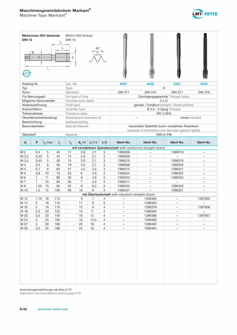
l1
d2
l2
d1
60
P
l3
D.48 www.lmt-tools.com
Metric ISO thread DIN 13
Metrisches ISO-Gewinde DIN 13
Anwendungsempfehlungen ab Seite D.70Application recommendations starting page D.70
Maschinengewindebohrer Markant®
Machine Taps Markant®
Katalog-Nr. Cat.-No. 6431 6432 6431 6432Typ Type HNorm Standard DIN 371 DIN 376 DIN 371 DIN 376Für Bohrungsart For type of hole Durchgangsgewinde Through holesMögliche Gewindetiefe Possible bore depth 3 x DNutenausführung Flute type gerade / Schälnut straight / Spiral pointedAnschnittform Chamfer form B 3,5 - 5 Gang ThreadsToleranzklasse Tolerance class ISO 2 (6H)Oberflächenbehandlung/Beschichtung
Subsequent treatment of surface/coating
– nitriert nitrided
Besonderheiten Special features besondere Stabilität durch verstärkten Nutenkern because of reinforced core diameter special rigidity
Werkstoff Material HSS-E-PM
d1 P l2 max l1 l3 d2 h9 h12 z Ident No. Ident No. Ident No. Ident No.
mit verstärktem Zylinderschaft with reinforced straight shankM 2 0,4 5 45 11 2,8 2,1 3 1396308 – 1396318 –M 2,2 0,45 5 45 12 2,8 2,1 3 1396309 – – –M 2,5 0,45 5 50 15 2,8 2,1 3 1396310 – 1396319 –M 3 0,5 6 56 18 3,5 2,7 3 1396306 – 1396320 –M 4 0,7 8 63 21 4,5 3,4 3 1396315 – 1396321 –M 5 0,8 10 70 25 6 4,9 3 1396324 – 1396322 –M 6 1 11 80 30 6 4,9 3 1396333 – 1396323 –M 7 1 10 80 30 7 5,5 3 1396311 – – –M 8 1,25 13 90 35 8 6,2 3 1396342 – 1396326 –M 10 1,5 15 100 39 10 8 3 1396351 – 1396327 –
mit Überlaufschaft with standard straight shankM 12 1,75 18 110 9 7 3 – 1396360 – 1397935M 14 2 16 110 11 9 3 – 1396363 – –M 16 2 18 110 12 9 4 – 1396379 – 1397936M 18 2,5 20 125 14 11 4 – 1396365 – –M 20 2,5 20 140 16 12 4 – 1396388 – 1397937M 24 3 25 160 18 14,5 4 – 1396460 – –M 27 3 30 160 20 16 4 – 1396462 – –M 30 3,5 35 180 22 18 4 – 1396464 – –
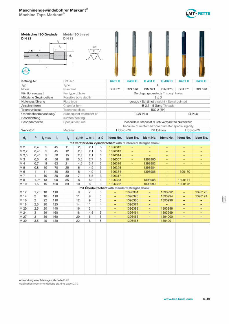
Gew
inde
n Th
read
ing
l1
d2
l2
d1
60
P
l3
D.49www.lmt-tools.com
Metric ISO thread DIN 13
Metrisches ISO Gewinde DIN 13
Anwendungsempfehlungen ab Seite D.70Application recommendations starting page D.70
Maschinengewindebohrer Markant®
Machine Taps Markant®
Katalog-Nr. Cat.-No. 6431 C 6432 C G 431 C G 432 C 6431 C 6432 CTyp Type HNorm Standard DIN 371 DIN 376 DIN 371 DIN 376 DIN 371 DIN 376Für Bohrungsart For type of hole Durchgangsgewinde Through holesMögliche Gewindetiefe Possible bore depth 3 x DNutenausführung Flute type gerade / Schälnut straight / Spiral pointedAnschnittform Chamfer form B 3,5 - 5 Gang ThreadsToleranzklasse Tolerance class ISO 2 (6H)Oberflächenbehandlung/Beschichtung
Subsequent treatment of surface/coating
TiCN Plus IQ Plus
Besonderheiten Special features besondere Stabilität durch verstärkten Nutenkern because of reinforced core diameter special rigidity
Werkstoff Material HSS-E-PM
d1 P l2 max l1 l3 d2 h9 h12 z Ident No. Ident No. Ident No. Ident No. Ident No. Ident No.
mit verstärktem Zylinderschaft with reinforced straight shankM 2 0,4 5 45 11 2,8 2,1 3 1396312 – – – – –M 2,2 0,45 5 45 12 2,8 2,1 3 1396313 – – – – –M 2,5 0,45 5 50 15 2,8 2,1 3 1396314 – – – – –M 3 0,5 6 56 18 3,5 2,7 3 1396307 – 1393980 – – –M 4 0,7 8 63 21 4,5 3,4 3 1396316 – 1393982 – – –M 5 0,8 10 70 25 6 4,9 3 1396325 – 1393984 – – –M 6 1 11 80 30 6 4,9 3 1396334 – 1393986 – 1390170 –M 7 1 10 80 30 7 5,5 3 1396317 – – – – –M 8 1,25 13 90 35 8 6,2 3 1396343 – 1393988 – 1390171 –M 10 1,5 15 100 39 10 8 3 1396352 – 1393990 – 1390172 –
mit Überlaufschaft with standard straight shankM 12 1,75 18 110 9 7 3 – 1396361 – 1393992 – 1390173M 14 2 16 110 11 9 3 – 1396370 – 1393994 – 1390174M 16 2 22 110 12 9 3 – 1396380 – 1393996 – –M 18 2,5 20 125 14 11 4 – 1396371 – – – –M 20 2,5 20 140 16 12 4 – 1396389 – 1393998 – –M 24 3 36 160 18 14,5 5 – 1396461 – 1393999 – –M 27 3 36 160 20 16 5 – 1396463 – 1394000 – –M 30 3,5 40 180 22 18 5 – 1396465 – 1394001 – –
PM Edition HSS-E-PM
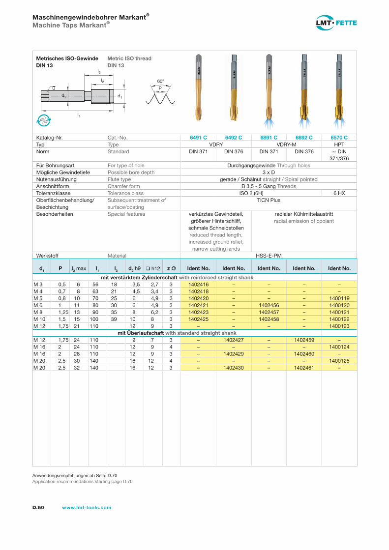
l1
d2
l2
d1
60
P
l3
D.50 www.lmt-tools.com
Metric ISO thread DIN 13
Metrisches ISO-Gewinde DIN 13
Anwendungsempfehlungen ab Seite D.70Application recommendations starting page D.70
Maschinengewindebohrer Markant®
Machine Taps Markant®
Katalog-Nr. Cat.-No. 6491 C 6492 C 6891 C 6892 C 6570 CTyp Type VDRY VDRY-M HPTNorm Standard DIN 371 DIN 376 DIN 371 DIN 376 DIN
371/376Für Bohrungsart For type of hole Durchgangsgewinde Through holesMögliche Gewindetiefe Possible bore depth 3 x DNutenausführung Flute type gerade / Schälnut straight / Spiral pointedAnschnittform Chamfer form B 3,5 - 5 Gang ThreadsToleranzklasse Tolerance class ISO 2 (6H) 6 HXOberflächenbehandlung/Beschichtung
Subsequent treatment of surface/coating
TiCN Plus
Besonderheiten Special features verkürztes Gewindeteil, größerer Hinterschliff,
schmale Schneidstollen reduced thread length, increased ground relief,
narrow cutting lands
radialer Kühlmittelaustritt radial emission of coolant
Werkstoff Material HSS-E-PM
d1 P l2 max l1 l3 d2 h9 h12 z Ident No. Ident No. Ident No. Ident No. Ident No.
mit verstärktem Zylinderschaft with reinforced straight shankM 3 0,5 6 56 18 3,5 2,7 3 1402416 – – – –M 4 0,7 8 63 21 4,5 3,4 3 1402418 – – – –M 5 0,8 10 70 25 6 4,9 3 1402420 – – – 1400119M 6 1 11 80 30 6 4,9 3 1402421 – 1402456 – 1400120M 8 1,25 13 90 35 8 6,2 3 1402423 – 1402457 – 1400121M 10 1,5 15 100 39 10 8 3 1402425 – 1402458 – 1400122M 12 1,75 21 110 12 9 3 – – – – 1400123
mit Überlaufschaft with standard straight shankM 12 1,75 24 110 9 7 3 – 1402427 – 1402459 –M 16 2 24 110 12 9 4 – – – – 1400124M 16 2 28 110 12 9 3 – 1402429 – 1402460 –M 20 2,5 30 140 16 12 4 – – – – 1400125M 20 2,5 32 140 16 12 3 – 1402430 – 1402461 –
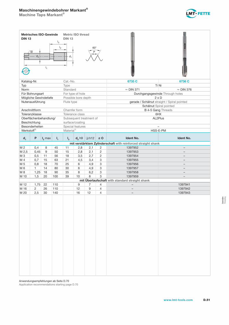
Gew
inde
n Th
read
ing
l1
d2
l2
d1
60
P
l3
D.51www.lmt-tools.com
Metric ISO thread DIN 13
Metrisches ISO-Gewinde DIN 13
Anwendungsempfehlungen ab Seite D.70Application recommendations starting page D.70
Maschinengewindebohrer Markant®
Machine Taps Markant®
Katalog-Nr. Cat.-No. 6735 C 6736 CTyp Type Ti NiNorm Standard DIN 371 DIN 376Für Bohrungsart For type of hole Durchgangsgewinde Through holesMögliche Gewindetiefe Possible bore depth 2 x DNutenausführung Flute type gerade / Schälnut straight / Spiral pointed
Schälnut Spiral pointedAnschnittform Chamfer form B 4-5 Gang ThreadsToleranzklasse Tolerance class 6HXOberflächenbehandlung/Beschichtung
Subsequent treatment of surface/coating
AL2Plus
Besonderheiten Special features –Werkstoff1) Material1) HSS-E-PM
d1 P l2 max l1 l3 d2 h9 h12 z Ident No. Ident No.
mit verstärktem Zylinderschaft with reinforced straight shankM 2 0,4 8 45 11 2,8 2,1 2 1397952 –M 2,5 0,45 9 50 15 2,8 2,1 2 1397953 –M 3 0,5 11 56 18 3,5 2,7 2 1397954 –M 4 0,7 15 63 21 4,5 3,4 3 1397955 –M 5 0,8 18 70 25 6 4,9 3 1397956 –M 6 1 14 80 30 6 4,9 3 1397957 –M 8 1,25 18 90 35 8 6,2 3 1397958 –M 10 1,5 20 100 39 10 8 3 1397959 –
mit Überlaufschaft with standard straight shankM 12 1,75 22 110 9 7 4 – 1397941M 16 2 26 110 12 9 4 – 1397942M 20 2,5 30 140 16 12 4 – 1397943
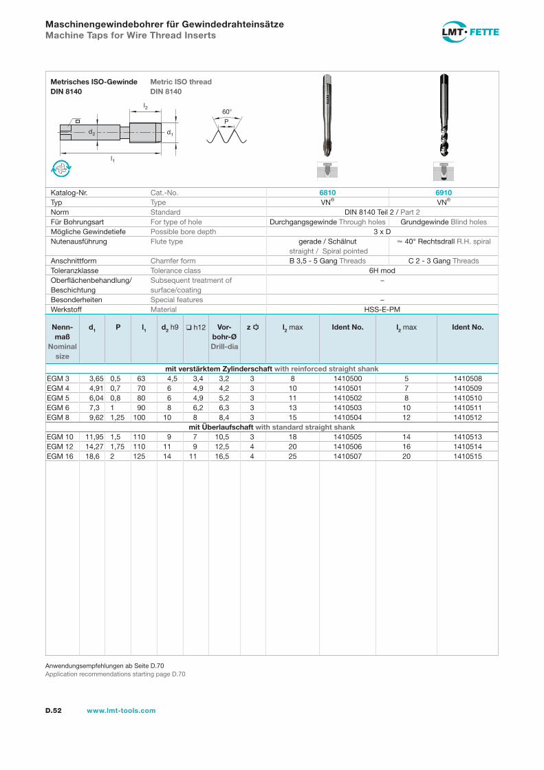
l1
d2
l2
d1
60
P
D.52 www.lmt-tools.com
Metric ISO thread DIN 8140
Metrisches ISO-Gewinde DIN 8140
Anwendungsempfehlungen ab Seite D.70Application recommendations starting page D.70
Maschinengewindebohrer für GewindedrahteinsätzeMachine Taps for Wire Thread Inserts
Katalog-Nr. Cat.-No. 6810 6910Typ Type VN® VN®
Norm Standard DIN 8140 Teil 2 / Part 2Für Bohrungsart For type of hole Durchgangsgewinde Through holes Grundgewinde Blind holesMögliche Gewindetiefe Possible bore depth 3 x DNutenausführung Flute type gerade / Schälnut
straight / Spiral pointed 40° Rechtsdrall R.H. spiral
Anschnittform Chamfer form B 3,5 - 5 Gang Threads C 2 - 3 Gang ThreadsToleranzklasse Tolerance class 6H modOberflächenbehandlung/Beschichtung
Subsequent treatment of surface/coating
–
Besonderheiten Special features –Werkstoff Material HSS-E-PM
Nenn-maß
Nominal size
d1 P l1 d2 h9 h12 Vor-bohr-Ø Drill-dia
z l2 max Ident No. l2 max Ident No.
mit verstärktem Zylinderschaft with reinforced straight shankEGM 3 3,65 0,5 63 4,5 3,4 3,2 3 8 1410500 5 1410508EGM 4 4,91 0,7 70 6 4,9 4,2 3 10 1410501 7 1410509EGM 5 6,04 0,8 80 6 4,9 5,2 3 11 1410502 8 1410510EGM 6 7,3 1 90 8 6,2 6,3 3 13 1410503 10 1410511EGM 8 9,62 1,25 100 10 8 8,4 3 15 1410504 12 1410512
mit Überlaufschaft with standard straight shankEGM 10 11,95 1,5 110 9 7 10,5 3 18 1410505 14 1410513EGM 12 14,27 1,75 110 11 9 12,5 4 20 1410506 16 1410514EGM 16 18,6 2 125 14 11 16,5 4 25 1410507 20 1410515
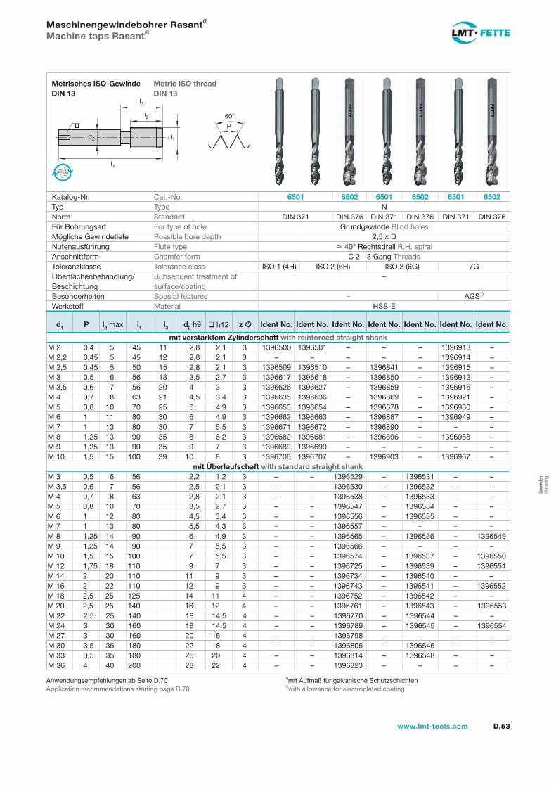
Gew
inde
n Th
read
ing
l1
d2
l2
d1
60
P
l3
D.53www.lmt-tools.com
Metric ISO thread DIN 13
Metrisches ISO-Gewinde DIN 13
1)mit Aufmaß für galvanische Schutzschichten1)with allowance for electroplated coating
Anwendungsempfehlungen ab Seite D.70Application recommendations starting page D.70
Maschinengewindebohrer Rasant®
Machine taps Rasant®
Katalog-Nr. Cat.-No. 6501 6502 6501 6502 6501 6502Typ Type NNorm Standard DIN 371 DIN 376 DIN 371 DIN 376 DIN 371 DIN 376Für Bohrungsart For type of hole Grundgewinde Blind holesMögliche Gewindetiefe Possible bore depth 2,5 x DNutenausführung Flute type 40° Rechtsdrall R.H. spiralAnschnittform Chamfer form C 2 - 3 Gang ThreadsToleranzklasse Tolerance class ISO 1 (4H) ISO 2 (6H) ISO 3 (6G) 7GOberflächenbehandlung/Beschichtung
Subsequent treatment of surface/coating
–
Besonderheiten Special features – AGS1)
Werkstoff Material HSS-E
d1 P l2 max l1 l3 d2 h9 h12 z Ident No. Ident No. Ident No. Ident No. Ident No. Ident No. Ident No.
mit verstärktem Zylinderschaft with reinforced straight shankM 2 0,4 5 45 11 2,8 2,1 3 1396500 1396501 – – – 1396913 –M 2,2 0,45 5 45 12 2,8 2,1 3 – – – – – 1396914 –M 2,5 0,45 5 50 15 2,8 2,1 3 1396509 1396510 – 1396841 – 1396915 –M 3 0,5 6 56 18 3,5 2,7 3 1396617 1396618 – 1396850 – 1396912 –M 3,5 0,6 7 56 20 4 3 3 1396626 1396627 – 1396859 – 1396916 –M 4 0,7 8 63 21 4,5 3,4 3 1396635 1396636 – 1396869 – 1396921 –M 5 0,8 10 70 25 6 4,9 3 1396653 1396654 – 1396878 – 1396930 –M 6 1 11 80 30 6 4,9 3 1396662 1396663 – 1396887 – 1396949 –M 7 1 13 80 30 7 5,5 3 1396671 1396672 – 1396890 – – –M 8 1,25 13 90 35 8 6,2 3 1396680 1396681 – 1396896 – 1396958 –M 9 1,25 13 90 35 9 7 3 1396689 1396690 – – – – –M 10 1,5 15 100 39 10 8 3 1396706 1396707 – 1396903 – 1396967 –
mit Überlaufschaft with standard straight shankM 3 0,5 6 56 2,2 1,2 3 – – 1396529 – 1396531 – –M 3,5 0,6 7 56 2,5 2,1 3 – – 1396530 – 1396532 – –M 4 0,7 8 63 2,8 2,1 3 – – 1396538 – 1396533 – –M 5 0,8 10 70 3,5 2,7 3 – – 1396547 – 1396534 – –M 6 1 12 80 4,5 3,4 3 – – 1396556 – 1396535 – –M 7 1 13 80 5,5 4,3 3 – – 1396557 – – – –M 8 1,25 14 90 6 4,9 3 – – 1396565 – 1396536 – 1396549M 9 1,25 14 90 7 5,5 3 – – 1396566 – – – –M 10 1,5 15 100 7 5,5 3 – – 1396574 – 1396537 – 1396550M 12 1,75 18 110 9 7 3 – – 1396725 – 1396539 – 1396551M 14 2 20 110 11 9 3 – – 1396734 – 1396540 – –M 16 2 22 110 12 9 3 – – 1396743 – 1396541 – 1396552M 18 2,5 25 125 14 11 4 – – 1396752 – 1396542 – –M 20 2,5 25 140 16 12 4 – – 1396761 – 1396543 – 1396553M 22 2,5 25 140 18 14,5 4 – – 1396770 – 1396544 – –M 24 3 30 160 18 14,5 4 – – 1396789 – 1396545 – 1396554M 27 3 30 160 20 16 4 – – 1396798 – – – –M 30 3,5 35 180 22 18 4 – – 1396805 – 1396546 – –M 33 3,5 35 180 25 20 4 – – 1396814 – 1396548 – –M 36 4 40 200 28 22 4 – – 1396823 – – – –
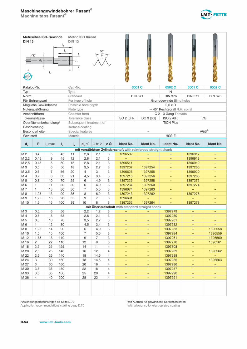
l1
d2
l2
d1
60
P
l3
D.54 www.lmt-tools.com
Metric ISO thread DIN 13
Metrisches ISO-Gewinde DIN 13
1)mit Aufmaß für galvanische Schutzschichten1)with allowance for electroplated coating
Anwendungsempfehlungen ab Seite D.70Application recommendations starting page D.70
Maschinengewindebohrer Rasant®
Machine taps Rasant®
Katalog-Nr. Cat.-No. 6501 C 6502 C 6501 C 6502 CTyp Type NNorm Standard DIN 371 DIN 376 DIN 371 DIN 376Für Bohrungsart For type of hole Grundgewinde Blind holesMögliche Gewindetiefe Possible bore depth 2,5 x DNutenausführung Flute type 40° Rechtsdrall R.H. spiralAnschnittform Chamfer form C 2 - 3 Gang ThreadsToleranzklasse Tolerance class ISO 2 (6H) ISO 3 (6G) ISO 2 (6H) 7GOberflächenbehandlung/Beschichtung
Subsequent treatment of surface/coating
TiCN Plus
Besonderheiten Special features – AGS1)
Werkstoff Material HSS-E
d1 P l2 max l1 l3 d2 h9 h12 z Ident No. Ident No. Ident No. Ident No. Ident No.
mit verstärktem Zylinderschaft with reinforced straight shankM 2 0,4 5 45 11 2,8 2,1 3 1396502 – – 1396917 –M 2,2 0,45 9 45 12 2,8 2,1 3 – – – 1396918 –M 2,5 0,45 5 50 15 2,8 2,1 3 1396511 – – 1396919 –M 3 0,5 6 56 18 3,5 2,7 3 1397207 1397254 – 1397266 –M 3,5 0,6 7 56 20 4 3 3 1396628 1397255 – 1396920 –M 4 0,7 8 63 21 4,5 3,4 3 1397216 1397256 – 1397268 –M 5 0,8 10 70 25 6 4,9 3 1397225 1397258 – 1397272 –M 6 1 11 80 30 6 4,9 3 1397234 1397260 – 1397274 –M 7 1 13 80 30 7 5,5 3 1396674 1397263 – – –M 8 1,25 13 90 35 8 6,2 3 1397243 1397262 – 1397276 –M 9 1,25 13 90 35 9 7 3 1396691 – – – –M 10 1,5 15 100 39 10 8 3 1397252 1397264 – 1397278 –
mit Überlaufschaft with standard straight shankM 3 0,5 6 56 2,2 1,2 3 – – 1397279 – –M 4 0,7 8 63 2,8 2,1 3 – – 1397280 – –M 5 0,8 10 70 3,5 2,7 3 – – 1397281 – –M 6 1 12 80 4,5 3,4 3 – – 1397282 – –M 8 1,25 14 90 6 4,9 3 – – 1397283 – 1396558M 10 1,5 15 100 7 5,5 3 – – 1397284 – 1396559M 12 1,75 18 110 9 7 3 – – 1397261 – 1396560M 16 2 22 110 12 9 3 – – 1397270 – 1396561M 18 2,5 25 125 14 11 4 – – 1397308 – –M 20 2,5 25 140 16 12 4 – – 1397289 – 1396562M 22 2,5 25 140 18 14,5 4 – – 1397288 – –M 24 3 30 160 18 14,5 4 – – 1397285 – 1396563M 27 3 30 160 20 16 4 – – 1397286 – –M 30 3,5 35 180 22 18 4 – – 1397287 – –M 33 3,5 35 180 25 20 4 – – 1397290 – –M 36 4 40 200 28 22 4 – – 1397291 – –
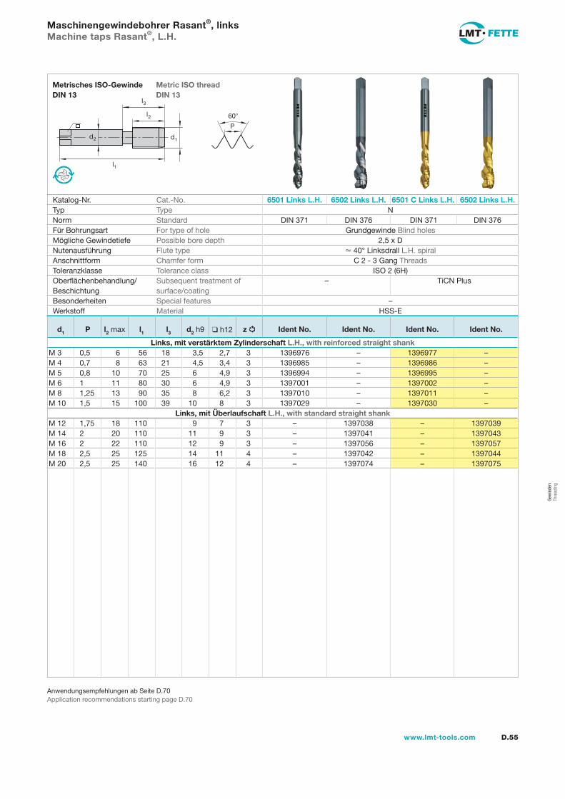
Gew
inde
n Th
read
ing
l1
d2
l2
d1
60
P
l3
D.55www.lmt-tools.com
Metric ISO thread DIN 13
Metrisches ISO-Gewinde DIN 13
Anwendungsempfehlungen ab Seite D.70Application recommendations starting page D.70
Maschinengewindebohrer Rasant®, linksMachine taps Rasant®, L.H.
Katalog-Nr. Cat.-No. 6501 Links L.H. 6502 Links L.H. 6501 C Links L.H. 6502 Links L.H.Typ Type NNorm Standard DIN 371 DIN 376 DIN 371 DIN 376Für Bohrungsart For type of hole Grundgewinde Blind holesMögliche Gewindetiefe Possible bore depth 2,5 x DNutenausführung Flute type 40° Linksdrall L.H. spiralAnschnittform Chamfer form C 2 - 3 Gang ThreadsToleranzklasse Tolerance class ISO 2 (6H)Oberflächenbehandlung/Beschichtung
Subsequent treatment of surface/coating
– TiCN Plus
Besonderheiten Special features –Werkstoff Material HSS-E
d1 P l2 max l1 l3 d2 h9 h12 z Ident No. Ident No. Ident No. Ident No.
Links, mit verstärktem Zylinderschaft L.H., with reinforced straight shankM 3 0,5 6 56 18 3,5 2,7 3 1396976 – 1396977 –M 4 0,7 8 63 21 4,5 3,4 3 1396985 – 1396986 –M 5 0,8 10 70 25 6 4,9 3 1396994 – 1396995 –M 6 1 11 80 30 6 4,9 3 1397001 – 1397002 –M 8 1,25 13 90 35 8 6,2 3 1397010 – 1397011 –M 10 1,5 15 100 39 10 8 3 1397029 – 1397030 –
Links, mit Überlaufschaft L.H., with standard straight shankM 12 1,75 18 110 9 7 3 – 1397038 – 1397039M 14 2 20 110 11 9 3 – 1397041 – 1397043M 16 2 22 110 12 9 3 – 1397056 – 1397057M 18 2,5 25 125 14 11 4 – 1397042 – 1397044M 20 2,5 25 140 16 12 4 – 1397074 – 1397075
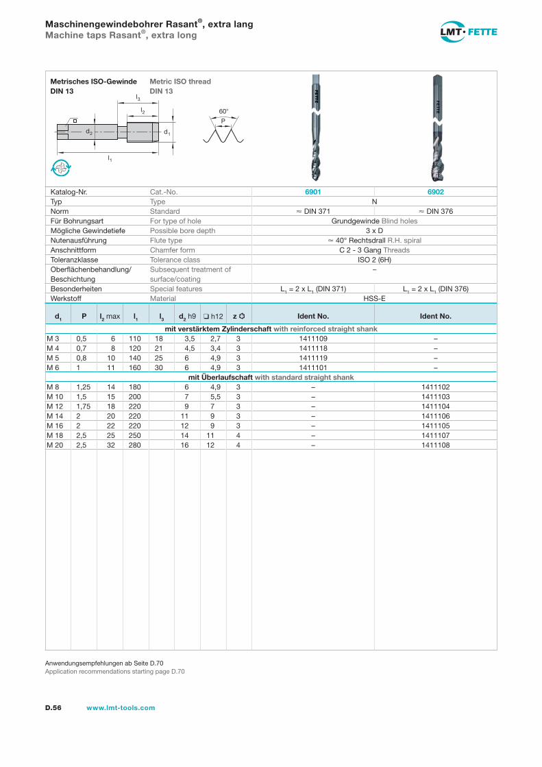
l1
d2
l2
d1
60
P
l3
D.56 www.lmt-tools.com
Metric ISO thread DIN 13
Metrisches ISO-Gewinde DIN 13
Anwendungsempfehlungen ab Seite D.70Application recommendations starting page D.70
Maschinengewindebohrer Rasant®, extra langMachine taps Rasant®, extra long
Katalog-Nr. Cat.-No. 6901 6902Typ Type NNorm Standard DIN 371 DIN 376Für Bohrungsart For type of hole Grundgewinde Blind holesMögliche Gewindetiefe Possible bore depth 3 x DNutenausführung Flute type 40° Rechtsdrall R.H. spiralAnschnittform Chamfer form C 2 - 3 Gang ThreadsToleranzklasse Tolerance class ISO 2 (6H)Oberflächenbehandlung/Beschichtung
Subsequent treatment of surface/coating
–
Besonderheiten Special features L1 = 2 x L1 (DIN 371) L1 = 2 x L1 (DIN 376)Werkstoff Material HSS-E
d1 P l2 max l1 l3 d2 h9 h12 z Ident No. Ident No.
mit verstärktem Zylinderschaft with reinforced straight shankM 3 0,5 6 110 18 3,5 2,7 3 1411109 –M 4 0,7 8 120 21 4,5 3,4 3 1411118 –M 5 0,8 10 140 25 6 4,9 3 1411119 –M 6 1 11 160 30 6 4,9 3 1411101 –
mit Überlaufschaft with standard straight shankM 8 1,25 14 180 6 4,9 3 – 1411102M 10 1,5 15 200 7 5,5 3 – 1411103M 12 1,75 18 220 9 7 3 – 1411104M 14 2 20 220 11 9 3 – 1411106M 16 2 22 220 12 9 3 – 1411105M 18 2,5 25 250 14 11 4 – 1411107M 20 2,5 32 280 16 12 4 – 1411108
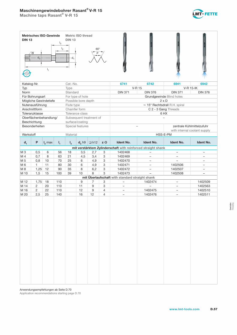
Gew
inde
n Th
read
ing
l1
d2
l2
d1
60
P
l3
D.57www.lmt-tools.com
Metric ISO thread DIN 13
Metrisches ISO-Gewinde DIN 13
Anwendungsempfehlungen ab Seite D.70Application recommendations starting page D.70
Maschinengewindebohrer Rasant® V-R 15Machine taps Rasant® V-R 15
Katalog-Nr. Cat.-No. 6741 6742 6941 6942Typ Type V-R 15 V-R 15-IKNorm Standard DIN 371 DIN 376 DIN 371 DIN 376Für Bohrungsart For type of hole Grundgewinde Blind holesMögliche Gewindetiefe Possible bore depth 2 x DNutenausführung Flute type 15° Rechtsdrall R.H. spiralAnschnittform Chamfer form C 2 - 3 Gang ThreadsToleranzklasse Tolerance class 6 HXOberflächenbehandlung/Beschichtung
Subsequent treatment of surface/coating
–
Besonderheiten Special features – zentrale Kühlmittelzufuhr with internal coolant supply
Werkstoff Material HSS-E-PM
d1 P l2 max l1 l3 d2 h9 h12 z Ident No. Ident No. Ident No. Ident No.
mit verstärktem Zylinderschaft with reinforced straight shankM 3 0,5 6 56 18 3,5 2,7 3 1402468 – – –M 4 0,7 8 63 21 4,5 3,4 3 1402469 – – –M 5 0,8 10 70 25 6 4,9 3 1402470 – – –M 6 1 11 80 30 6 4,9 3 1402471 – 1402506 –M 8 1,25 12 90 35 8 6,2 3 1402472 – 1402507 –M 10 1,5 15 100 39 10 8 3 1402473 – 1402508 –
mit Überlaufschaft with standard straight shankM 12 1,75 18 110 9 7 3 – 1402474 – 1402509M 14 2 20 110 11 9 3 – – – 1402563M 16 2 22 110 12 9 4 – 1402475 – 1402510M 20 2,5 25 140 16 12 4 – 1402476 – 1402511
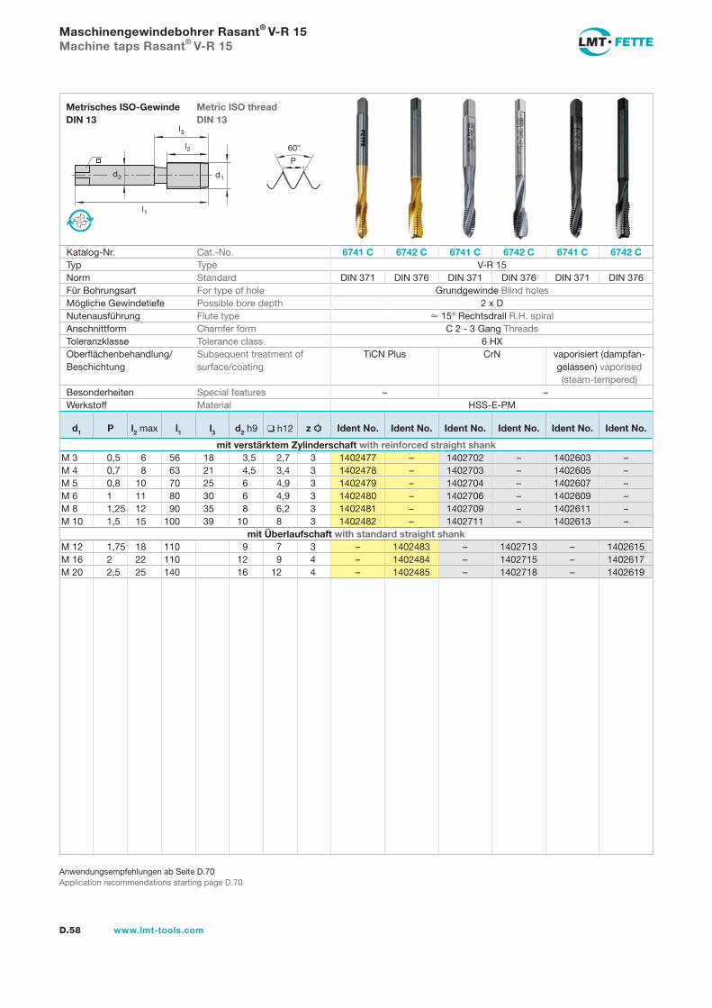
l1
d2
l2
d1
60
P
l3
D.58 www.lmt-tools.com
Metric ISO thread DIN 13
Metrisches ISO-Gewinde DIN 13
Anwendungsempfehlungen ab Seite D.70Application recommendations starting page D.70
Maschinengewindebohrer Rasant® V-R 15Machine taps Rasant® V-R 15
Katalog-Nr. Cat.-No. 6741 C 6742 C 6741 C 6742 C 6741 C 6742 CTyp Type V-R 15Norm Standard DIN 371 DIN 376 DIN 371 DIN 376 DIN 371 DIN 376Für Bohrungsart For type of hole Grundgewinde Blind holesMögliche Gewindetiefe Possible bore depth 2 x DNutenausführung Flute type 15° Rechtsdrall R.H. spiralAnschnittform Chamfer form C 2 - 3 Gang ThreadsToleranzklasse Tolerance class 6 HXOberflächenbehandlung/Beschichtung
Subsequent treatment of surface/coating
TiCN Plus CrN vaporisiert (dampfan-gelassen) vaporised (steam-tempered)
Besonderheiten Special features – –Werkstoff Material HSS-E-PM
d1 P l2 max l1 l3 d2 h9 h12 z Ident No. Ident No. Ident No. Ident No. Ident No. Ident No.
mit verstärktem Zylinderschaft with reinforced straight shankM 3 0,5 6 56 18 3,5 2,7 3 1402477 – 1402702 – 1402603 –M 4 0,7 8 63 21 4,5 3,4 3 1402478 – 1402703 – 1402605 –M 5 0,8 10 70 25 6 4,9 3 1402479 – 1402704 – 1402607 –M 6 1 11 80 30 6 4,9 3 1402480 – 1402706 – 1402609 –M 8 1,25 12 90 35 8 6,2 3 1402481 – 1402709 – 1402611 –M 10 1,5 15 100 39 10 8 3 1402482 – 1402711 – 1402613 –
mit Überlaufschaft with standard straight shankM 12 1,75 18 110 9 7 3 – 1402483 – 1402713 – 1402615M 16 2 22 110 12 9 4 – 1402484 – 1402715 – 1402617M 20 2,5 25 140 16 12 4 – 1402485 – 1402718 – 1402619
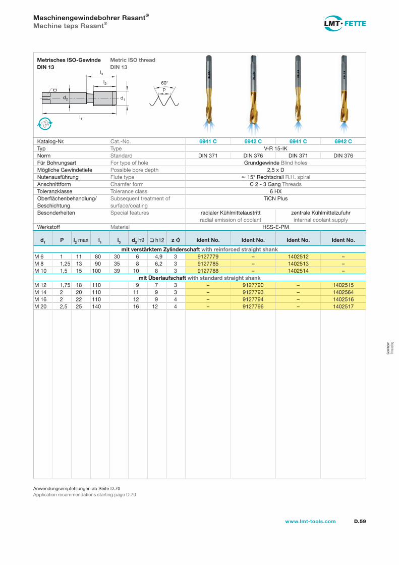
Gew
inde
n Th
read
ing
l1
d2
l2
d1
60
P
l3
D.59www.lmt-tools.com
Metric ISO thread DIN 13
Metrisches ISO-Gewinde DIN 13
Anwendungsempfehlungen ab Seite D.70Application recommendations starting page D.70
Maschinengewindebohrer Rasant®
Machine taps Rasant®
Katalog-Nr. Cat.-No. 6941 C 6942 C 6941 C 6942 CTyp Type V-R 15-IKNorm Standard DIN 371 DIN 376 DIN 371 DIN 376Für Bohrungsart For type of hole Grundgewinde Blind holesMögliche Gewindetiefe Possible bore depth 2,5 x DNutenausführung Flute type 15° Rechtsdrall R.H. spiralAnschnittform Chamfer form C 2 - 3 Gang ThreadsToleranzklasse Tolerance class 6 HXOberflächenbehandlung/Beschichtung
Subsequent treatment of surface/coating
TiCN Plus
Besonderheiten Special features radialer Kühlmittelaustritt radial emission of coolant
zentrale Kühlmittelzufuhr internal coolant supply
Werkstoff Material HSS-E-PM
d1 P l2 max l1 l3 d2 h9 h12 z Ident No. Ident No. Ident No. Ident No.
mit verstärktem Zylinderschaft with reinforced straight shankM 6 1 11 80 30 6 4,9 3 9127779 – 1402512 –M 8 1,25 13 90 35 8 6,2 3 9127785 – 1402513 –M 10 1,5 15 100 39 10 8 3 9127788 – 1402514 –
mit Überlaufschaft with standard straight shankM 12 1,75 18 110 9 7 3 – 9127790 – 1402515M 14 2 20 110 11 9 3 – 9127793 – 1402564M 16 2 22 110 12 9 4 – 9127794 – 1402516M 20 2,5 25 140 16 12 4 – 9127796 – 1402517
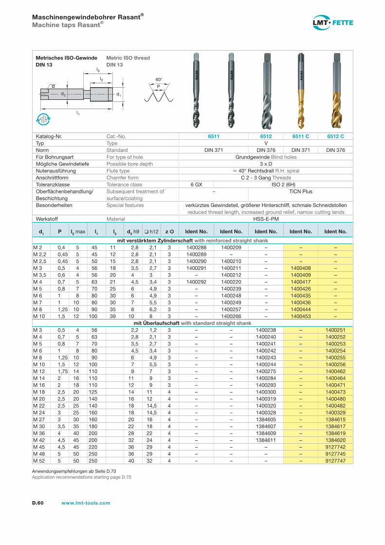
l1
d2
l2
d1
60
P
l3
D.60 www.lmt-tools.com
Metric ISO thread DIN 13
Metrisches ISO-Gewinde DIN 13
Anwendungsempfehlungen ab Seite D.70Application recommendations starting page D.70
Maschinengewindebohrer Rasant®
Machine taps Rasant®
Katalog-Nr. Cat.-No. 6511 6512 6511 C 6512 CTyp Type VNorm Standard DIN 371 DIN 376 DIN 371 DIN 376Für Bohrungsart For type of hole Grundgewinde Blind holesMögliche Gewindetiefe Possible bore depth 3 x DNutenausführung Flute type 40° Rechtsdrall R.H. spiralAnschnittform Chamfer form C 2 - 3 Gang ThreadsToleranzklasse Tolerance class 6 GX ISO 2 (6H)Oberflächenbehandlung/Beschichtung
Subsequent treatment of surface/coating
– TiCN Plus
Besonderheiten Special features verkürztes Gewindeteil, größerer Hinterschliff, schmale Schneidstollen reduced thread length, increased ground relief, narrow cutting lands
Werkstoff Material HSS-E-PM
d1 P l2 max l1 l3 d2 h9 h12 z Ident No. Ident No. Ident No. Ident No. Ident No.
mit verstärktem Zylinderschaft with reinforced straight shankM 2 0,4 5 45 11 2,8 2,1 3 1400288 1400209 – – –M 2,2 0,45 5 45 12 2,8 2,1 3 1400289 – – – –M 2,5 0,45 5 50 15 2,8 2,1 3 1400290 1400210 – – –M 3 0,5 4 56 18 3,5 2,7 3 1400291 1400211 – 1400408 –M 3,5 0,6 4 56 20 4 3 3 – 1400212 – 1400409 –M 4 0,7 5 63 21 4,5 3,4 3 1400292 1400220 – 1400417 –M 5 0,8 7 70 25 6 4,9 3 – 1400239 – 1400426 –M 6 1 8 80 30 6 4,9 3 – 1400248 – 1400435 –M 7 1 10 80 30 7 5,5 3 – 1400249 – 1400436 –M 8 1,25 10 90 35 8 6,2 3 – 1400257 – 1400444 –M 10 1,5 12 100 39 10 8 3 – 1400266 – 1400453 –
mit Überlaufschaft with standard straight shankM 3 0,5 4 56 2,2 1,2 3 – – 1400238 – 1400251M 4 0,7 5 63 2,8 2,1 3 – – 1400240 – 1400252M 5 0,8 7 70 3,5 2,7 3 – – 1400241 – 1400253M 6 1 8 80 4,5 3,4 3 – – 1400242 – 1400254M 8 1,25 10 90 6 4,9 3 – – 1400243 – 1400255M 10 1,5 12 100 7 5,5 3 – – 1400244 – 1400256M 12 1,75 14 110 9 7 3 – – 1400275 – 1400462M 14 2 16 110 11 9 3 – – 1400284 – 1400464M 16 2 18 110 12 9 3 – – 1400293 – 1400471M 18 2,5 20 125 14 11 4 – – 1400300 – 1400473M 20 2,5 20 140 16 12 4 – – 1400319 – 1400480M 22 2,5 25 140 18 14,5 4 – – 1400320 – 1400482M 24 3 25 160 18 14,5 4 – – 1400328 – 1400329M 27 3 30 160 20 16 4 – – 1384605 – 1384615M 30 3,5 35 180 22 18 4 – – 1384607 – 1384617M 36 4 40 200 28 22 4 – – 1384609 – 1384619M 42 4,5 45 200 32 24 4 – – 1384611 – 1384620M 45 4,5 45 220 36 29 4 – – – – 9127742M 48 5 50 250 36 29 4 – – – – 9127745M 52 5 50 250 40 32 4 – – – – 9127747
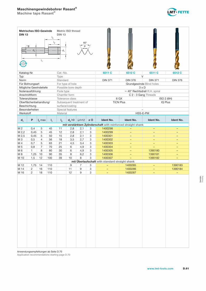
Gew
inde
n Th
read
ing
l1
d2
l2
d1
60
P
l3
D.61www.lmt-tools.com
Metric ISO thread DIN 13
Metrisches ISO-Gewinde DIN 13
Anwendungsempfehlungen ab Seite D.70Application recommendations starting page D.70
Maschinengewindebohrer Rasant®
Machine taps Rasant®
Katalog-Nr. Cat.-No. 6511 C 6512 C 6511 C 6512 CTyp Type VNorm Standard DIN 371 DIN 376 DIN 371 DIN 376Für Bohrungsart For type of hole Grundgewinde Blind holesMögliche Gewindetiefe Possible bore depth 3 x DNutenausführung Flute type 40° Rechtsdrall R.H. spiralAnschnittform Chamfer form C 2 - 3 Gang ThreadsToleranzklasse Tolerance class 6 GX ISO 2 (6H)Oberflächenbehandlung/Beschichtung
Subsequent treatment of surface/coating
TiCN Plus IQ Plus
Besonderheiten Special features –Werkstoff Material HSS-E-PM
d1 P l2 max l1 l3 d2 h9 h12 z Ident No. Ident No. Ident No. Ident No.
mit verstärktem Zylinderschaft with reinforced straight shankM 2 0,4 5 45 11 2,8 2,1 3 1400298 – – –M 2,2 0,45 5 45 12 2,8 2,1 3 1400299 – – –M 2,5 0,45 5 50 15 2,8 2,1 3 1400301 – – –M 3 0,5 4 56 18 3,5 2,7 3 1400302 – – –M 4 0,7 5 63 21 4,5 3,4 3 1400303 – – –M 5 0,8 7 70 25 6 4,9 3 1400304 – – –M 6 1 8 80 30 6 4,9 3 1400305 – 1390180 –M 8 1,25 10 90 35 8 6,2 3 1400306 – 1390181 –M 10 1,5 12 100 39 10 8 3 1400307 – 1390182 –
mit Überlaufschaft with standard straight shankM 12 1,75 14 110 9 7 3 – 1400285 – 1390183M 14 2 16 110 11 9 3 – 1400286 – 1390184M 16 2 18 110 12 9 3 – 1400287 – –
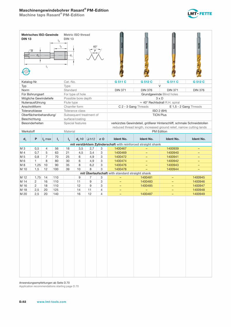
l1
d2
l2
d1
60
P
l3
D.62 www.lmt-tools.com
Metric ISO thread DIN 13
Metrisches ISO-Gewinde DIN 13
Anwendungsempfehlungen ab Seite D.70Application recommendations starting page D.70
Maschinengewindebohrer Rasant® PM-EditionMachine taps Rasant® PM-Edition
Katalog-Nr. Cat.-No. G 511 C G 512 C G 511 C G 512 CTyp Type VNorm Standard DIN 371 DIN 376 DIN 371 DIN 376Für Bohrungsart For type of hole Grundgewinde Blind holesMögliche Gewindetiefe Possible bore depth 3 x DNutenausführung Flute type 40° Rechtsdrall R.H. spiralAnschnittform Chamfer form C 2 - 3 Gang Threads E 1,5 - 2 Gang ThreadsToleranzklasse Tolerance class ISO 2 (6H)Oberflächenbehandlung/Beschichtung
Subsequent treatment of surface/coating
TiCN Plus
Besonderheiten Special features verkürztes Gewindeteil, größerer Hinterschliff, schmale Schneidstollen reduced thread length, increased ground relief, narrow cutting lands
Werkstoff Material PM Edition
d1 P l2 max l1 l3 d2 h9 h12 z Ident No. Ident No. Ident No. Ident No.
mit verstärktem Zylinderschaft with reinforced straight shankM 3 0,5 4 56 18 3,5 2,7 3 1400467 – 1400939 –M 4 0,7 5 63 21 4,5 3,4 3 1400469 – 1400940 –M 5 0,8 7 70 25 6 4,9 3 1400472 – 1400941 –M 6 1 8 80 30 6 4,9 3 1400474 – 1400942 –M 8 1,25 10 90 35 8 6,2 3 1400476 – 1400943 –M 10 1,5 12 100 39 10 8 3 1400478 – 1400944 –
mit Überlaufschaft with standard straight shankM 12 1,75 14 110 9 7 3 – 1400481 – 1400945M 14 2 16 110 11 9 3 – 1400483 – 1400946M 16 2 18 110 12 9 3 – 1400485 – 1400947M 18 2,5 20 125 14 11 4 – – – 1400948M 20 2,5 20 140 16 12 4 – 1400487 – 1400949
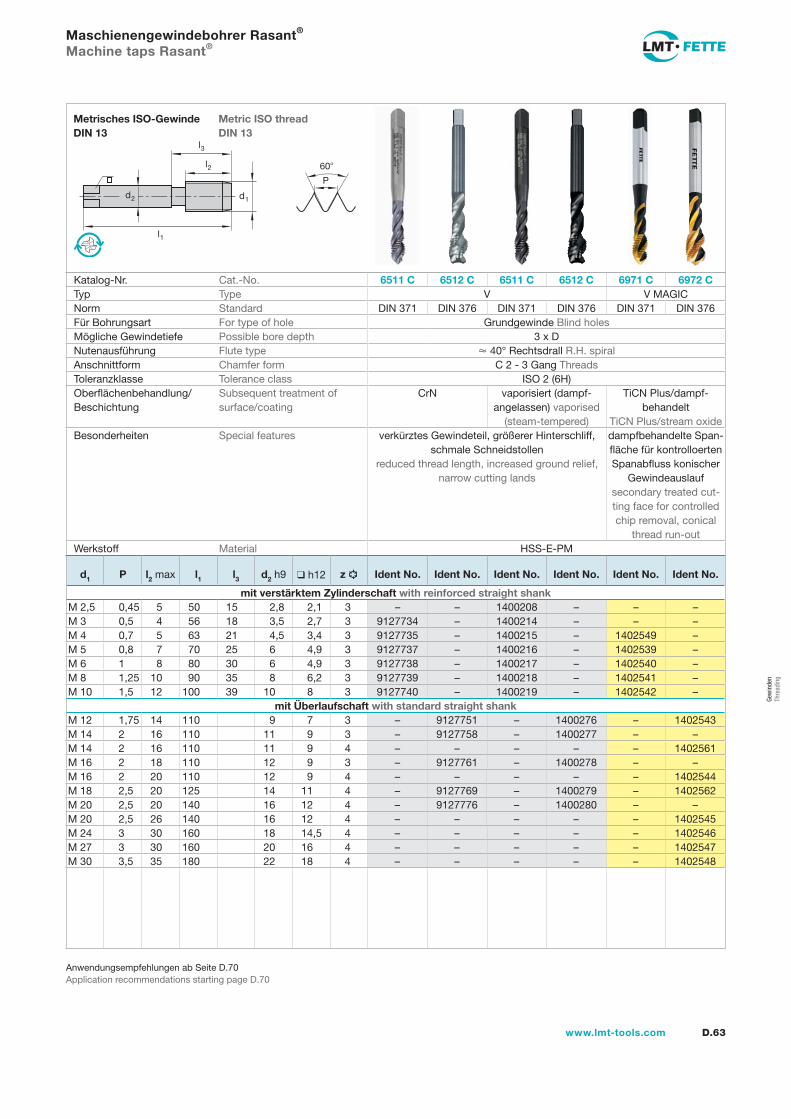
Gew
inde
n Th
read
ing
l1
d2
l2
d1
60
P
l3
D.63www.lmt-tools.com
Metric ISO thread DIN 13
Metrisches ISO-Gewinde DIN 13
Anwendungsempfehlungen ab Seite D.70Application recommendations starting page D.70
Maschienengewindebohrer Rasant®
Machine taps Rasant®
Katalog-Nr. Cat.-No. 6511 C 6512 C 6511 C 6512 C 6971 C 6972 CTyp Type V V MAGICNorm Standard DIN 371 DIN 376 DIN 371 DIN 376 DIN 371 DIN 376Für Bohrungsart For type of hole Grundgewinde Blind holesMögliche Gewindetiefe Possible bore depth 3 x DNutenausführung Flute type 40° Rechtsdrall R.H. spiralAnschnittform Chamfer form C 2 - 3 Gang ThreadsToleranzklasse Tolerance class ISO 2 (6H)Oberflächenbehandlung/Beschichtung
Subsequent treatment of surface/coating
CrN vaporisiert (dampf-angelassen) vaporised
(steam-tempered)
TiCN Plus/dampf-behandelt
TiCN Plus/stream oxideBesonderheiten Special features verkürztes Gewindeteil, größerer Hinterschliff,
schmale Schneidstollen reduced thread length, increased ground relief,
narrow cutting lands
dampfbehandelte Span-fläche für kontrolloerten Spanabfluss konischer
Gewindeauslauf secondary treated cut-ting face for controlled chip removal, conical
thread run-outWerkstoff Material HSS-E-PM
d1 P l2 max l1 l3 d2 h9 h12 z Ident No. Ident No. Ident No. Ident No. Ident No. Ident No.
mit verstärktem Zylinderschaft with reinforced straight shankM 2,5 0,45 5 50 15 2,8 2,1 3 – – 1400208 – – –M 3 0,5 4 56 18 3,5 2,7 3 9127734 – 1400214 – – –M 4 0,7 5 63 21 4,5 3,4 3 9127735 – 1400215 – 1402549 –M 5 0,8 7 70 25 6 4,9 3 9127737 – 1400216 – 1402539 –M 6 1 8 80 30 6 4,9 3 9127738 – 1400217 – 1402540 –M 8 1,25 10 90 35 8 6,2 3 9127739 – 1400218 – 1402541 –M 10 1,5 12 100 39 10 8 3 9127740 – 1400219 – 1402542 –
mit Überlaufschaft with standard straight shankM 12 1,75 14 110 9 7 3 – 9127751 – 1400276 – 1402543M 14 2 16 110 11 9 3 – 9127758 – 1400277 – –M 14 2 16 110 11 9 4 – – – – – 1402561M 16 2 18 110 12 9 3 – 9127761 – 1400278 – –M 16 2 20 110 12 9 4 – – – – – 1402544M 18 2,5 20 125 14 11 4 – 9127769 – 1400279 – 1402562M 20 2,5 20 140 16 12 4 – 9127776 – 1400280 – –M 20 2,5 26 140 16 12 4 – – – – – 1402545M 24 3 30 160 18 14,5 4 – – – – – 1402546M 27 3 30 160 20 16 4 – – – – – 1402547M 30 3,5 35 180 22 18 4 – – – – – 1402548
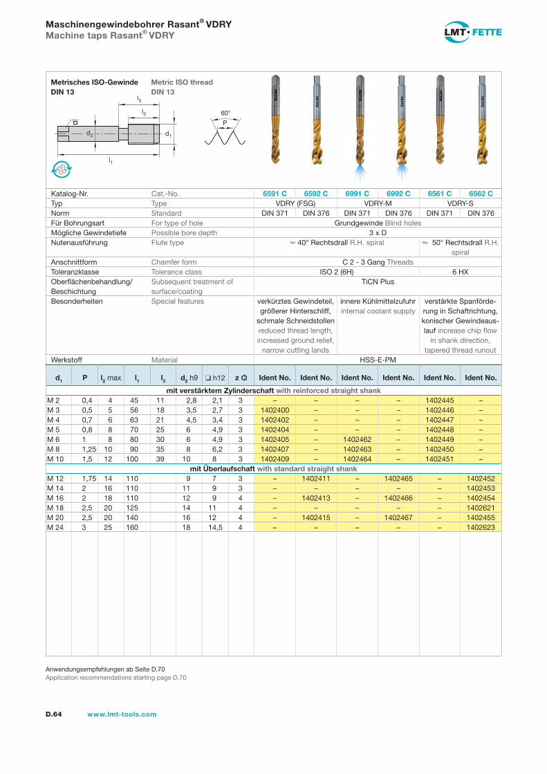
l1
d2
l2
d1
60
P
l3
D.64 www.lmt-tools.com
Metric ISO thread DIN 13
Metrisches ISO-Gewinde DIN 13
Anwendungsempfehlungen ab Seite D.70Application recommendations starting page D.70
Maschinengewindebohrer Rasant® VDRYMachine taps Rasant® VDRY
Katalog-Nr. Cat.-No. 6591 C 6592 C 6991 C 6992 C 6561 C 6562 CTyp Type VDRY (FSG) VDRY-M VDRY-SNorm Standard DIN 371 DIN 376 DIN 371 DIN 376 DIN 371 DIN 376Für Bohrungsart For type of hole Grundgewinde Blind holesMögliche Gewindetiefe Possible bore depth 3 x DNutenausführung Flute type 40° Rechtsdrall R.H. spiral 50° Rechtsdrall R.H.
spiralAnschnittform Chamfer form C 2 - 3 Gang ThreadsToleranzklasse Tolerance class ISO 2 (6H) 6 HXOberflächenbehandlung/Beschichtung
Subsequent treatment of surface/coating
TiCN Plus
Besonderheiten Special features verkürztes Gewindeteil, größerer Hinterschliff,
schmale Schneidstollen reduced thread length, increased ground relief,
narrow cutting lands
innere Kühlmittelzufuhr internal coolant supply
verstärkte Spanförde-rung in Schaftrichtung, konischer Gewindeaus-lauf increase chip flow
in shank direction, tapered thread runout
Werkstoff Material HSS-E-PM
d1 P l2 max l1 l3 d2 h9 h12 z Ident No. Ident No. Ident No. Ident No. Ident No. Ident No.
mit verstärktem Zylinderschaft with reinforced straight shankM 2 0,4 4 45 11 2,8 2,1 3 – – – – 1402445 –M 3 0,5 5 56 18 3,5 2,7 3 1402400 – – – 1402446 –M 4 0,7 6 63 21 4,5 3,4 3 1402402 – – – 1402447 –M 5 0,8 8 70 25 6 4,9 3 1402404 – – – 1402448 –M 6 1 8 80 30 6 4,9 3 1402405 – 1402462 – 1402449 –M 8 1,25 10 90 35 8 6,2 3 1402407 – 1402463 – 1402450 –M 10 1,5 12 100 39 10 8 3 1402409 – 1402464 – 1402451 –
mit Überlaufschaft with standard straight shankM 12 1,75 14 110 9 7 3 – 1402411 – 1402465 – 1402452M 14 2 16 110 11 9 3 – – – – – 1402453M 16 2 18 110 12 9 4 – 1402413 – 1402466 – 1402454M 18 2,5 20 125 14 11 4 – – – – – 1402621M 20 2,5 20 140 16 12 4 – 1402415 – 1402467 – 1402455M 24 3 25 160 18 14,5 4 – – – – – 1402623
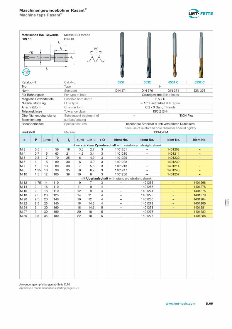
Gew
inde
n Th
read
ing
l1
d2
l2
d1
60
P
l3
D.65www.lmt-tools.com
Metric ISO threadDIN 13
Metrisches ISO-Gewinde DIN 13
Anwendungsempfehlungen ab Seite D.70Application recommendations starting page D.70
Maschinengewindebohrer Rasant®
Machine taps Rasant®
Katalog-Nr. Cat.-No. 6531 6532 6531 C 6532 CTyp Type HNorm Standard DIN 371 DIN 376 DIN 371 DIN 376Für Bohrungsart For type of hole Grundgewinde Blind holesMögliche Gewindetiefe Possible bore depth 2,5 x DNutenausführung Flute type 15° Rechtsdrall R.H. spiralAnschnittform Chamfer form C 2 - 3 Gang ThreadsToleranzklasse Tolerance class ISO 2 (6H)Oberflächenbehandlung/Beschichtung
Subsequent treatment of surface/coating
– TiCN Plus
Besonderheiten Special features besondere Stabilität durch verstärkten Nutenkern because of reinforced core diameter special rigidity
Werkstoff Material HSS-E-PM
d1 P l2 max l1 l3 d2 h9 h12 z Ident No. Ident No. Ident No. Ident No.
mit verstärktem Zylinderschaft with reinforced straight shankM 3 0,5 4 56 18 3,5 2,7 3 1401201 – 1401202 –M 4 0,7 5 63 21 4,5 3,4 3 1401210 – 1401211 –M 5 0,8 7 70 25 6 4,9 3 1401229 – 1401230 –M 6 1 8 80 30 6 4,9 3 1401238 – 1401239 –M 7 1 10 80 30 7 5,5 3 1401213 – 1401214 –M 8 1,25 10 90 35 8 6,2 3 1401247 – 1401248 –M 10 1,5 12 100 39 10 8 3 1401256 – 1401257 –
mit Überlaufschaft with standard straight shankM 12 1,75 14 110 9 7 3 – 1401265 – 1401266M 14 2 16 110 11 9 4 – 1401268 – 1401278M 16 2 18 110 12 9 4 – 1401274 – 1401275M 18 2,5 20 125 14 11 4 – 1401270 – 1401279M 20 2,5 20 140 16 12 4 – 1401283 – 1401284M 22 2,5 25 140 18 14,5 4 – 1401272 – 1401280M 24 3 30 160 18 14,5 5 – 1401273 – 1401281M 27 3 30 160 20 16 5 – 1401276 – 1401282M 30 3,5 35 180 22 18 5 – 1401277 – 1401288
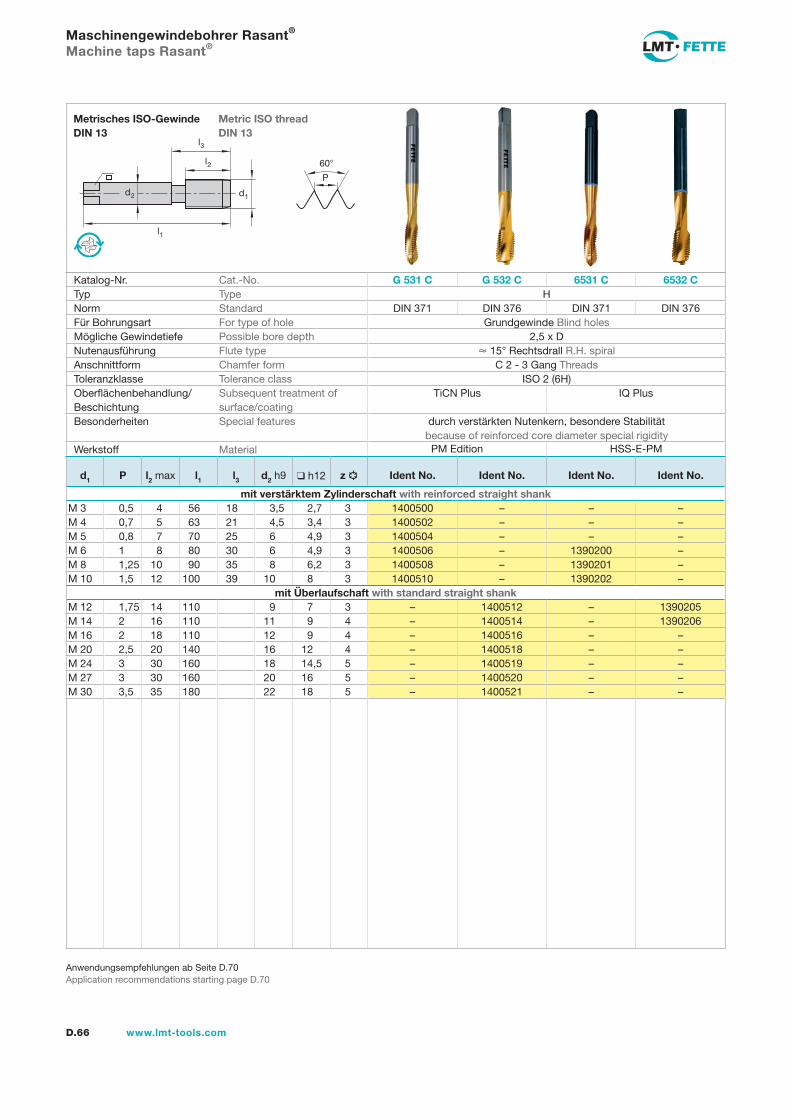
l1
d2
l2
d1
60
P
l3
D.66 www.lmt-tools.com
Metric ISO thread DIN 13
Metrisches ISO-Gewinde DIN 13
Anwendungsempfehlungen ab Seite D.70Application recommendations starting page D.70
Maschinengewindebohrer Rasant®
Machine taps Rasant®
Katalog-Nr. Cat.-No. G 531 C G 532 C 6531 C 6532 CTyp Type HNorm Standard DIN 371 DIN 376 DIN 371 DIN 376Für Bohrungsart For type of hole Grundgewinde Blind holesMögliche Gewindetiefe Possible bore depth 2,5 x DNutenausführung Flute type 15° Rechtsdrall R.H. spiralAnschnittform Chamfer form C 2 - 3 Gang ThreadsToleranzklasse Tolerance class ISO 2 (6H)Oberflächenbehandlung/Beschichtung
Subsequent treatment of surface/coating
TiCN Plus IQ Plus
Besonderheiten Special features durch verstärkten Nutenkern, besondere Stabilitätbecause of reinforced core diameter special rigidity
Werkstoff Material
d1 P l2 max l1 l3 d2 h9 h12 z Ident No. Ident No. Ident No. Ident No.
mit verstärktem Zylinderschaft with reinforced straight shankM 3 0,5 4 56 18 3,5 2,7 3 1400500 – – –M 4 0,7 5 63 21 4,5 3,4 3 1400502 – – –M 5 0,8 7 70 25 6 4,9 3 1400504 – – –M 6 1 8 80 30 6 4,9 3 1400506 – 1390200 –M 8 1,25 10 90 35 8 6,2 3 1400508 – 1390201 –M 10 1,5 12 100 39 10 8 3 1400510 – 1390202 –
mit Überlaufschaft with standard straight shankM 12 1,75 14 110 9 7 3 – 1400512 – 1390205M 14 2 16 110 11 9 4 – 1400514 – 1390206M 16 2 18 110 12 9 4 – 1400516 – –M 20 2,5 20 140 16 12 4 – 1400518 – –M 24 3 30 160 18 14,5 5 – 1400519 – –M 27 3 30 160 20 16 5 – 1400520 – –M 30 3,5 35 180 22 18 5 – 1400521 – –
HSS-E-PMPM Edition
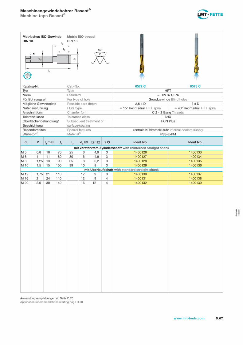
Gew
inde
n Th
read
ing
l1
d2
l2
d1
60
P
l3
D.67www.lmt-tools.com
Metric ISO thread DIN 13
Metrisches ISO-Gewinde DIN 13
Anwendungsempfehlungen ab Seite D.70Application recommendations starting page D.70
Maschinengewindebohrer Rasant®
Machine taps Rasant®
Katalog-Nr. Cat.-No. 6572 C 6573 CTyp Type HPTNorm Standard DIN 371/376Für Bohrungsart For type of hole Grundgewinde Blind holesMögliche Gewindetiefe Possible bore depth 2,5 x D 3 x DNutenausführung Flute type 15° Rechtsdrall R.H. spiral 40° Rechtsdrall R.H. spiralAnschnittform Chamfer form C 2 - 3 Gang ThreadsToleranzklasse Tolerance class 6HXOberflächenbehandlung/Beschichtung
Subsequent treatment of surface/coating
TiCN Plus
Besonderheiten Special features zentrale Kühlmittelzufuhr internal coolant supplyWerkstoff1) Material1) HSS-E-PM
d1 P l2 max l1 l3 d2 h9 h12 z Ident No. Ident No.
mit verstärktem Zylinderschaft with reinforced straight shankM 5 0,8 10 70 25 6 4,9 3 1400126 1400133M 6 1 11 80 30 6 4,9 3 1400127 1400134M 8 1,25 13 90 35 8 6,2 3 1400128 1400135M 10 1,5 15 100 39 10 8 3 1400129 1400136
mit Überlaufschaft with standard straight shankM 12 1,75 21 110 12 9 3 1400130 1400137M 16 2 24 110 12 9 4 1400131 1400138M 20 2,5 30 140 16 12 4 1400132 1400139
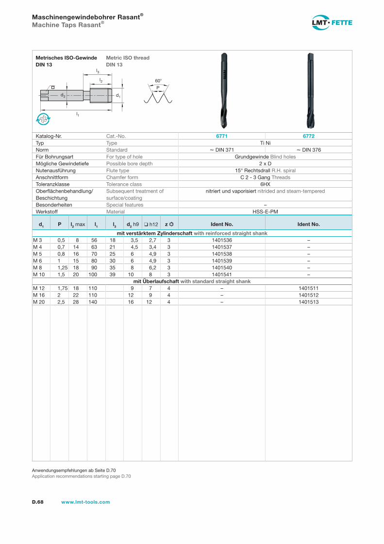
l1
d2
l2
d1
60
P
l3
D.68 www.lmt-tools.com
Metric ISO thread DIN 13
Metrisches ISO-Gewinde DIN 13
Anwendungsempfehlungen ab Seite D.70Application recommendations starting page D.70
Maschinengewindebohrer Rasant®
Machine Taps Rasant®
Katalog-Nr. Cat.-No. 6771 6772Typ Type Ti NiNorm Standard DIN 371 DIN 376Für Bohrungsart For type of hole Grundgewinde Blind holesMögliche Gewindetiefe Possible bore depth 2 x DNutenausführung Flute type 15° Rechtsdrall R.H. spiralAnschnittform Chamfer form C 2 - 3 Gang ThreadsToleranzklasse Tolerance class 6HXOberflächenbehandlung/Beschichtung
Subsequent treatment of surface/coating
nitriert und vaporisiert nitrided and steam-tempered
Besonderheiten Special features –Werkstoff Material HSS-E-PM
d1 P l2 max l1 l3 d2 h9 h12 z Ident No. Ident No.
mit verstärktem Zylinderschaft with reinforced straight shankM 3 0,5 8 56 18 3,5 2,7 3 1401536 –M 4 0,7 14 63 21 4,5 3,4 3 1401537 –M 5 0,8 16 70 25 6 4,9 3 1401538 –M 6 1 15 80 30 6 4,9 3 1401539 –M 8 1,25 18 90 35 8 6,2 3 1401540 –M 10 1,5 20 100 39 10 8 3 1401541 –
mit Überlaufschaft with standard straight shankM 12 1,75 18 110 9 7 4 – 1401511M 16 2 22 110 12 9 4 – 1401512M 20 2,5 28 140 16 12 4 – 1401513
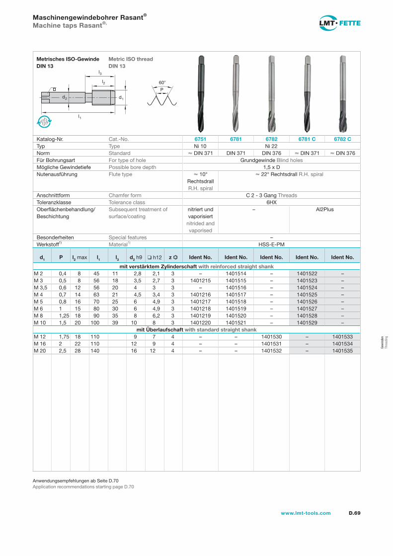
Gew
inde
n Th
read
ing
l1
d2
l2
d1
60
P
l3
D.69www.lmt-tools.com
Metric ISO thread DIN 13
Metrisches ISO-Gewinde DIN 13
Anwendungsempfehlungen ab Seite D.70Application recommendations starting page D.70
Maschinengewindebohrer Rasant®
Machine taps Rasant®,
Katalog-Nr. Cat.-No. 6751 6781 6782 6781 C 6782 CTyp Type Ni 10 Ni 22Norm Standard DIN 371 DIN 371 DIN 376 DIN 371 DIN 376Für Bohrungsart For type of hole Grundgewinde Blind holesMögliche Gewindetiefe Possible bore depth 1,5 x DNutenausführung Flute type 10°
Rechtsdrall R.H. spiral
22° Rechtsdrall R.H. spiral
Anschnittform Chamfer form C 2 - 3 Gang ThreadsToleranzklasse Tolerance class 6HXOberflächenbehandlung/Beschichtung
Subsequent treatment of surface/coating
nitriert und vaporisiert
nitrided and vaporised
– Al2Plus
Besonderheiten Special features –Werkstoff1) Material1) HSS-E-PM
d1 P l2 max l1 l3 d2 h9 h12 z Ident No. Ident No. Ident No. Ident No. Ident No.
mit verstärktem Zylinderschaft with reinforced straight shankM 2 0,4 8 45 11 2,8 2,1 3 – 1401514 – 1401522 –M 3 0,5 8 56 18 3,5 2,7 3 1401215 1401515 – 1401523 –M 3,5 0,6 12 56 20 4 3 3 – 1401516 – 1401524 –M 4 0,7 14 63 21 4,5 3,4 3 1401216 1401517 – 1401525 –M 5 0,8 16 70 25 6 4,9 3 1401217 1401518 – 1401526 –M 6 1 15 80 30 6 4,9 3 1401218 1401519 – 1401527 –M 8 1,25 18 90 35 8 6,2 3 1401219 1401520 – 1401528 –M 10 1,5 20 100 39 10 8 3 1401220 1401521 – 1401529 –
mit Überlaufschaft with standard straight shankM 12 1,75 18 110 9 7 4 – – 1401530 – 1401533M 16 2 22 110 12 9 4 – – 1401531 – 1401534M 20 2,5 28 140 16 12 4 – – 1401532 – 1401535
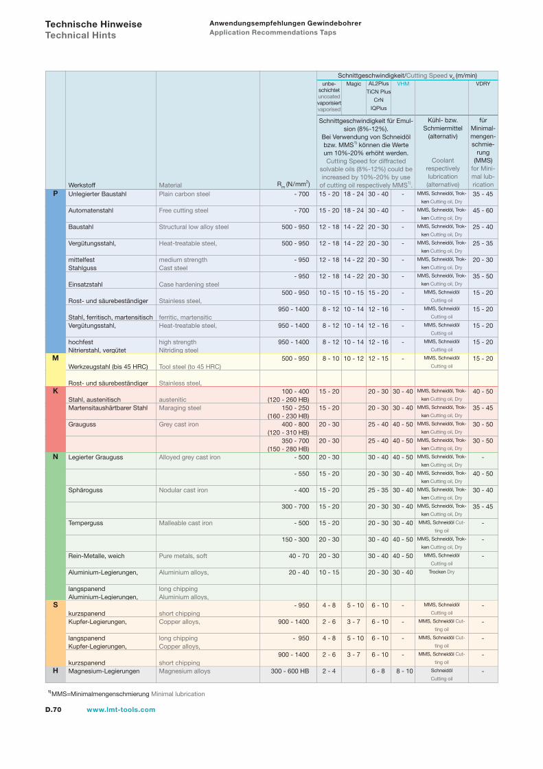
D.70 www.lmt-tools.com
Anwendungsempfehlungen Gewindebohrer Application Recommendations Taps
Werkstoff Material Rm (N/mm2)
Schnittgeschwindigkeit/Cutting Speed vc (m/min)unbe-
schichtetuncoatedvaporisiertvaporised
Schnittgeschwindigkeit für Emul-sion (8%-12%).
Bei Verwendung von Schneidöl bzw. MMS1) können die Werte um 10%-20% erhöht werden.Cutting Speed for diffracted
solvable oils (8%-12%) could be increased by 10%-20% by use
of cutting oil respectively MMS1).
Kühl- bzw. Schmiermittel
(alternativ)
Coolant respectively lubrication (alternative)
für Minimal-mengen-schmie-
rung (MMS)
for Mini-mal lub-rication
Magic AL2Plus
TiCN Plus
CrN
IQPlus
VHM VDRY
Technische Hinweise Technical Hints
- 700
- 700
500 - 950
500 - 950
- 950
- 950
500 - 950
950 - 1400
950 - 1400
950 - 1400
500 - 950
100 - 400 (120 - 260 HB) 150 - 250 (160 - 230 HB) 400 - 800 (120 - 310 HB) 350 - 700 (150 - 280 HB) - 500
- 550
- 400
300 - 700
- 500
150 - 300
40 - 70
20 - 40
- 950
900 - 1400
- 950
900 - 1400
300 - 600 HB
15 - 20
15 - 20
12 - 18
12 - 18
12 - 18
12 - 18
10 - 15
8 - 12
8 - 12
8 - 12
8 - 10
15 - 20
15 - 20
20 - 30
20 - 30
20 - 30
15 - 20
15 - 20
15 - 20
15 - 20
20 - 30
20 - 30
10 - 15
4 - 8
2 - 6
4 - 8
2 - 6
2 - 4
18 - 24
18 - 24
14 - 22 14 - 22
14 - 22
14 - 22
10 - 15
10 - 14
10 - 14
10 - 14
10 - 12
5 - 10
3 - 7
5 - 10
3 - 7
-
-
-
-
-
-
-
-
-
-
-
30 - 40
30 - 40
40 - 50
40 - 50
40 - 50
30 - 40
30 - 40
30 - 40
30 - 40
40 - 50
40 - 50
30 - 40
-
-
-
-
8 - 10
MMS, Schneidöl, Trok-
ken Cutting oil, Dry
MMS, Schneidöl, Trok-
ken Cutting oil, Dry
MMS, Schneidöl, Trok-
ken Cutting oil, Dry
MMS, Schneidöl, Trok-
ken Cutting oil, Dry
MMS, Schneidöl, Trok-
ken Cutting oil, Dry
MMS, Schneidöl, Trok-
ken Cutting oil, Dry
MMS, Schneidöl
Cutting oil
MMS, Schneidöl
Cutting oil
MMS, Schneidöl
Cutting oil
MMS, Schneidöl
Cutting oil
MMS, Schneidöl
Cutting oil
MMS, Schneidöl, Trok-
ken Cutting oil, Dry
MMS, Schneidöl, Trok-
ken Cutting oil, Dry
MMS, Schneidöl, Trok-
ken Cutting oil, Dry
MMS, Schneidöl, Trok-
ken Cutting oil, Dry
MMS, Schneidöl, Trok-
ken Cutting oil, Dry
MMS, Schneidöl, Trok-
ken Cutting oil, Dry
MMS, Schneidöl, Trok-
ken Cutting oil, Dry
MMS, Schneidöl, Trok-
ken Cutting oil, Dry
MMS, Schneidöl Cut-
ting oil
MMS, Schneidöl, Trok-
ken Cutting oil, Dry
MMS, Schneidöl
Cutting oil
Trocken Dry
MMS, Schneidöl
Cutting oil
MMS, Schneidöl Cut-
ting oil
MMS, Schneidöl Cut-
ting oil
MMS, Schneidöl Cut-
ting oil
Schneidöl
Cutting oil
35 - 45
45 - 60
25 - 40
25 - 35
20 - 30
35 - 50
15 - 20
15 - 20
15 - 20
15 - 20
15 - 20
40 - 50
35 - 45
30 - 50
30 - 50
-
40 - 50
30 - 40
35 - 45
-
-
-
-
-
-
-
-
1)MMS=Minimalmengenschmierung Minimal lubrication
Unlegierter Baustahl Plain carbon steel Automatenstahl Free cutting steel Baustahl Structural low alloy steel Vergütungsstahl, Heat-treatable steel,
mittelfest medium strengthStahlguss Cast steel Einsatzstahl Case hardening steel Rost- und säurebeständiger Stainless steel,
Stahl, ferritisch, martensitisch ferritic, martensiticVergütungsstahl, Heat-treatable steel,
hochfest high strengthNitrierstahl, vergütet Nitriding steel Werkzeugstahl (bis 45 HRC) Tool steel (to 45 HRC) Rost- und säurebeständiger Stainless steel,
Stahl, austenitisch austeniticMartensitaushärtbarer Stahl Maraging steel
Grauguss Grey cast iron
Legierter Grauguss Alloyed grey cast iron
Sphäroguss Nodular cast iron
Temperguss Malleable cast iron
Rein-Metalle, weich Pure metals, soft Aluminium-Legierungen, Aluminium alloys,
langspanend long chippingAluminium-Legierungen, Aluminium alloys,
kurzspanend short chippingKupfer-Legierungen, Copper alloys,
langspanend long chippingKupfer-Legierungen, Copper alloys,
kurzspanend short chippingMagnesium-Legierungen Magnesium alloys
30 - 40
30 - 40
20 - 30
20 - 30
20 - 30
20 - 30
15 - 20
12 - 16
12 - 16
12 - 16
12 - 15
20 - 30
20 - 30
25 - 40
25 - 40
30 - 40
20 - 30
25 - 35
20 - 30
20 - 30
30 - 40
30 - 40
20 - 30
6 - 10
6 - 10
6 - 10
6 - 10
6 - 8
N
S
H
P
K
M

D.71www.lmt-tools.com
NotizenNotes
Gew
inde
n Th
read
ing
D.72 www.lmt-tools.com
Gewindebohrer metrisch-feinTaps metric fine
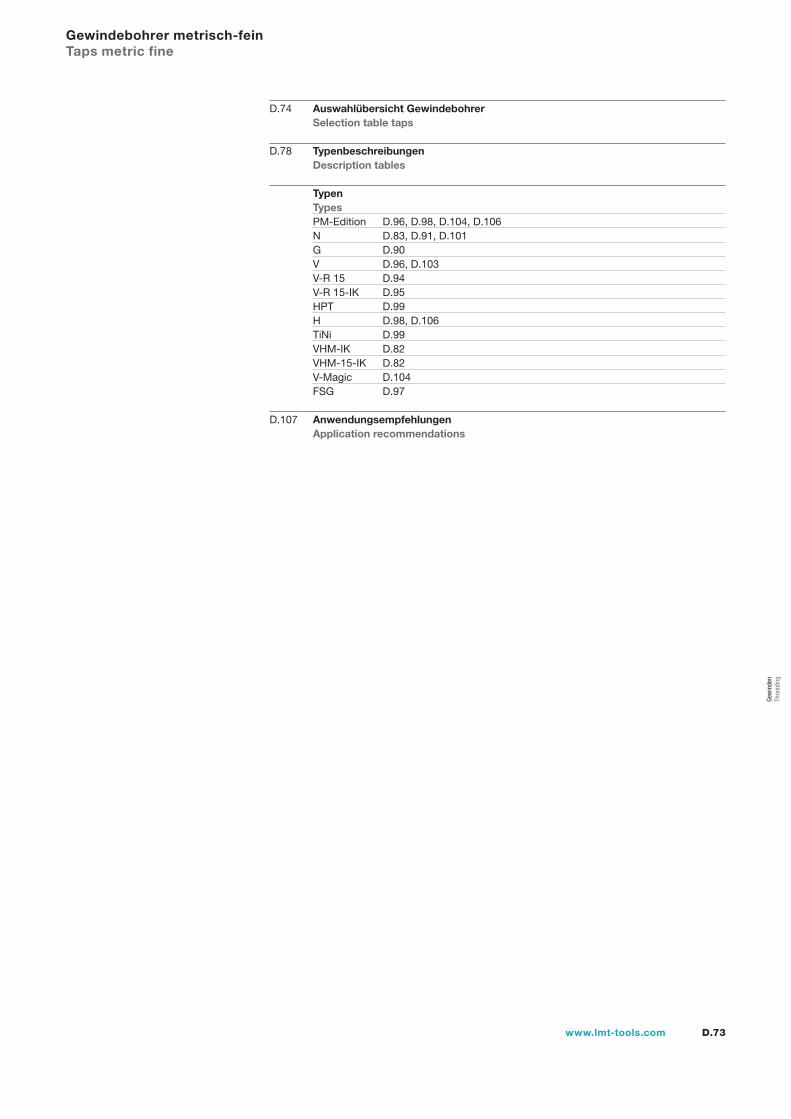
D.73www.lmt-tools.com
D.74 Auswahlübersicht Gewindebohrer Selection table taps
D.78 Typenbeschreibungen Description tables
Typen Types PM-Edition D.96, D.98, D.104, D.106 N D.83, D.91, D.101 G D.90 V D.96, D.103 V-R 15 D.94 V-R 15-IK D.95 HPT D.99 H D.98, D.106 TiNi D.99 VHM-IK D.82 VHM-15-IK D.82 V-Magic D.104 FSG D.97
D.107 Anwendungsempfehlungen Application recommendations
Gewindebohrer metrisch-fein Taps metric fine
Gew
inde
n Th
read
ing
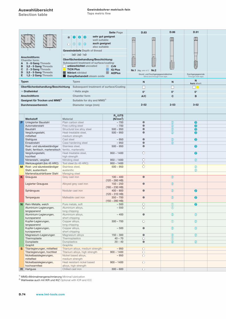
D.74 www.lmt-tools.com
Auswahlübersicht Selection table
Typen Types
Anschnittform:Chamfer form:A 5 - 6 Gang ThreadsB 3,5 - 5 Gang ThreadsC 2 - 3 Gang ThreadsD 3,5 - 5 Gang ThreadsE 1,5 - 2 Gang Threads
Oberflächenbehandlung/Beschichtung:Subsequent treatment of surface/coating:
unbeschichtet uncoatedTiCN PlusNitriert nitridedDampfbehandelt steam oxide
0°
N
A/C
2-52
Seite Page D.83 D.86 D.91
1) MMS=Minimalmengenschmierung Minimal lubrication2) Wahlweise auch mit IKR und IKZ Optional with ICR and ICC
N
S
H
P
K
M
Rm/UTSWerkstoff Material (N/mm2)Unlegierter Baustahl Plain carbon steel – 700Automatenstahl Free cutting steel – 700Baustahl Structural low alloy steel 500 – 950Vergütungsstahl, Heat-treatable steel, 500 – 950mittelfest medium strengthStahlguss Cast steel – 950Einsatzstahl Case hardening steel – 950Rost- und säurebeständiger Stainless steel, 500 – 950Stahl, ferritisch, martensitisch ferritic, martensiticVergütungsstahl, Heat-treatable steel, 950 – 1400hochfest high strengthNitrierstahl, vergütet Nitriding steel 950 – 1400Werkzeugstahl (bis 45 HRC) Tool steel (to 45 HRC) 950 – 1400Rost- und säurebeständiger Stainless steel, 500 – 950Stahl, austenitisch austeniticMartensitaushärtbarer Stahl Maraging steelGrauguss Grey cast iron 100 – 400 (120 – 260 HB)Legierter Grauguss Alloyed grey cast iron 150 – 250 (160 – 230 HB)Sphäroguss Nodular cast iron 400 – 800 (120 – 310 HB)Temperguss Malleable cast iron 350 – 700 (150 – 280 HB)Rein-Metalle, weich Pure metals, soft – 500Aluminium-Legierungen, Aluminium alloys, – 550langspanend long chippingAluminium-Legierungen, Aluminium alloys, – 400kurzspanend short chippingKupfer-Legierungen, Copper alloys, 300 – 700langspanend long chippingKupfer-Legierungen, Copper alloys, – 500kurzspanend short chippingMagnesium-Legierungen Magnesium alloys 150 – 300Thermoplaste Thermoplastics 40 – 70Duroplaste Duroplastics 20 – 40Graphit GraphiteTitanlegierungen, mittelfest Titanium alloys, medium strength – 950Titanlegierungen, hochfest Titanium alloys, high strength 900 – 1400Nickelbasislegierungen, Nickel based alloys, – 950mittelfest medium strengthNickelbasislegierungen, Heat resistant nickel based 900 – 1400hochwarmfest alloys, high strengthHartguss Chilled cast iron 300 – 600
sehr gut geeignetwell suitableauch geeignetalso suitable
Geweindetiefe Depth of thread
~ 3xD 2xD 1xD
Grund- und DurchgangsgewindebohrerBlind and through hole taps
Oberflächenbehandlung/Beschichtung Subsequent treatment of surface/Coating
Drallwinkel ≈ Helix angle
Anschnittform Chamfer form
Geeignet für Trocken und MMS1) Suitable for dry and MMS1)
Durchmesserbereich Diameter range (mm)
Nr.1 2tlg. sets of 2 Nr.2
N
0°
C
2-53
CrNIQ PlusAl2Plus
Nkurz short
0°
B
3-52
Gewindebohrer metrisch-fein Taps metric fine
DurchgangsgewindeThrough hole taps
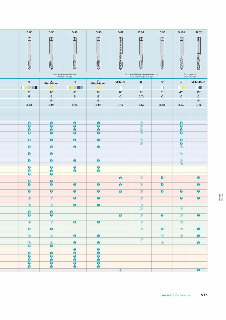
D.75www.lmt-tools.com
Gew
inde
n Th
read
ing
D.96 D.96 D.98 D.98 D.82 D.88 D.90 D.101 D.82
V
0°
B
6-30
VPM-Edition
0°
B
8-20
DurchgangsgewindebohrerThrough hole taps
H
0°
B
6-24
HPM-Edition
0°
B
3-20
Grund- und DurchgangsgewindebohrerBlind and through hole taps
VHM-IK N G2
0° 0° 0°
C C/D C
8-12 2-52 3-30
VHM-15-IK
15°
C
8-12
N
3-45
40°
C
GrundgewindeBlind hole taps
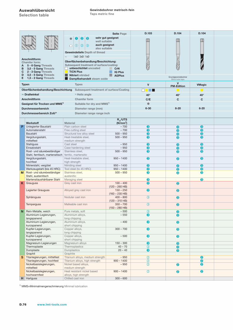
D.76 www.lmt-tools.com
Auswahlübersicht Selection table
Typen Types
Anschnittform:Chamfer form:A 5 - 6 Gang ThreadsB 3,5 - 5 Gang ThreadsC 2 - 3 Gang ThreadsD 3,5 - 5 Gang ThreadsE 1,5 - 2 Gang Threads
Oberflächenbehandlung/Beschichtung:Subsequent treatment of surface/coating:
unbeschichtet uncoatedTiCN PlusNitriert nitridedDampfbehandelt steam oxide
40°
V
C/E
6-30
Seite Page D.103 D.104 D.104
1) MMS=Minimalmengenschmierung Minimal lubrication
N
S
H
P
K
M
Rm/UTSWerkstoff Material (N/mm2)Unlegierter Baustahl Plain carbon steel – 700Automatenstahl Free cutting steel – 700Baustahl Structural low alloy steel 500 – 950Vergütungsstahl, Heat-treatable steel, 500 – 950mittelfest medium strengthStahlguss Cast steel – 950Einsatzstahl Case hardening steel – 950Rost- und säurebeständiger Stainless steel, 500 – 950Stahl, ferritisch, martensitisch ferritic, martensiticVergütungsstahl, Heat-treatable steel, 950 – 1400hochfest high strengthNitrierstahl, vergütet Nitriding steel 950 – 1400Werkzeugstahl (bis 45 HRC) Tool steel (to 45 HRC) 950 – 1400Rost- und säurebeständiger Stainless steel, 500 – 950Stahl, austenitisch austeniticMartensitaushärtbarer Stahl Maraging steelGrauguss Grey cast iron 100 – 400 (120 – 260 HB)Legierter Grauguss Alloyed grey cast iron 150 – 250 (160 – 230 HB)Sphäroguss Nodular cast iron 400 – 800 (120 – 310 HB)Temperguss Malleable cast iron 350 – 700 (150 – 280 HB)Rein-Metalle, weich Pure metals, soft – 500Aluminium-Legierungen, Aluminium alloys, – 550langspanend long chippingAluminium-Legierungen, Aluminium alloys, – 400kurzspanend short chippingKupfer-Legierungen, Copper alloys, 300 – 700langspanend long chippingKupfer-Legierungen, Copper alloys, – 500kurzspanend short chippingMagnesium-Legierungen Magnesium alloys 150 – 300Thermoplaste Thermoplastics 40 – 70Duroplaste Duroplastics 20 – 40Graphit GraphiteTitanlegierungen, mittelfest Titanium alloys, medium strength – 950Titanlegierungen, hochfest Titanium alloys, high strength 900 – 1400Nickelbasislegierungen, Nickel based alloys, – 950mittelfest medium strengthNickelbasislegierungen, Heat resistant nickel based 900 – 1400hochwarmfest alloys, high strengthHartguss Chilled cast iron 300 – 600
sehr gut geeignetwell suitableauch geeignetalso suitable
Geweindetiefe Depth of thread
~ 3xD 2xD 1xD
Oberflächenbehandlung/Beschichtung Subsequent treatment of surface/Coating
Drallwinkel ≈ Helix angle
Anschnittform Chamfer form
Geeignet für Trocken und MMS1) Suitable for dry and MMS1)
Durchmesserbereich Diameter range (mm)
Durchmesserbereich Zoll/" Diameter range range inch
VPM-Edition
40°
C
8-20
CrNIQ PlusAl2Plus
VMagic
40°
C
6-20
Gewindebohrer metrisch-fein Taps metric fine
GrundgewindebohrerBlind hole taps
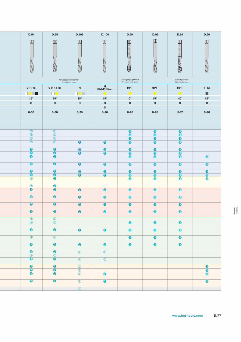
D.77www.lmt-tools.com
D.94 D.95 D.106 D.106 D.99 D.99 D.99 D.99
V-R 15
15°
C
8-30
V-R 15-IK
15°
C
8-30
H
15°
C
3-20
HPM-Edition
15°
C
8-20
HPT HPT HPT
0° 15° 40°
B C C
8-20 8-20 8-20
GrundgewindebohrerBlind hole taps
Ti Ni
15°
C
8-20
DurchgangsgewindeThrough hole taps
GrundgewindeBlind hole taps
Gew
inde
n Th
read
ing
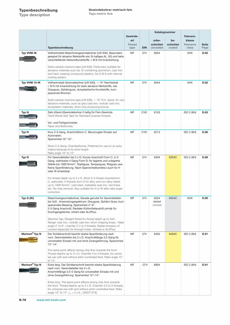
D.78 www.lmt-tools.com
Typenbeschreibung Type desciption
Gewindebohrer metrisch fein Taps metric fine
Katalognummer
Gewinde- Toleranz-
art unbe- be- klasse
Thread schichtet schichtet Tolerance SeiteTypenbeschreibung type DIN uncoated coated class Page
Typ VHM-IK Vollhartmetall-Maschinengewindebohrer (LW 630). Besonders geeignet für abrasive Werkstoffe wie: Si-haltiges AL, GG und harte verschleißende Verbundkunststoffe. ≥ M 6 mit Innenkühlung.
Solid carbide machine taps (LW 630). Particulary suitable for abrasive materials such as: Si-containing aluminium, cast iron and hard, wearing compound plastics. As of M 6 with internal cooling system.
MF 374 6004 6HX D.82
Typ VHM 15-IK Vollhartmetall-Gewindebohrer (LW 630), 15° Rechtsdrall ≥ M 6 mit Innenkühlung für stark abrasive Werkstoffe, wie Grauguss, Sphäroguss, duroplastische Kunststoffe, kurz-spanende Bronzen.
Solid carbide machine taps (LW 630), 15° R.H. spiral, for very abrasive materials, such as grey cast iron, nodular cast iron, duroplastic materials, short chip producing bronze.
MF 374 6044 6HX D.82
Typ N Satz-(Hand-)Gewindebohrer 2-teilig für Fein-Gewinde.Hand (Serial Set) Taps for Standard (coarse) threads.
Vor- und FertigschneiderTaper and Bottomely
MF 2181 6103 ISO 2 (6H) D.83
Typ N Kurz 2-3 Gang. Anschnittform C. Bevorzugter Einsatz auf Automaten.Spanwinkel 10°-12°.
Short 2-3 Gang. Chamberforme. Preferred for use on an auto-matics because of its short lengthRake angle 10° to 12°
MF 2181 6213 ISO 2 (6H) D.86
Typ N Für Gewindetiefen bis 2 x D. Kurzer Anschnitt Form C, 2–3 Gang, wahlweise 4 Gang Form D; für legierte und unlegierte Stähle bis 1000 N/mm2, Stahlguss, Temperguss, Rotguss usw. Keine Spanförderung. Nach Spanwinkelkorrektur auch für H oder W einsetzbar.
For thread depth up to 2 x D. Short 2–3 thread chamferform C, optionally, 4-threads form D for alloy and non-alloy steels up to 1000 N/mm2, cast steel, malleable cast iron, red brass etc. No chip removal. Also suitable for H or W after rake angle correction.
MF 374 6304 6304C ISO 2 (6H) D.88
Typ G (IK) Maschinengewindebohrer, Gerade genutet für Gewindetiefen bis 3xD , Anwendungsspektrum: Grauguss, Sphäro-Guss, kurz-spanendes Messing, Spanwinkel 4°-6°, 2-3 Gang Anschnitt, Radialer Kühlmittelaustritt primär für Durchgangslöcher, nitriert oder AL2Plus.
Machine Tap, Straight fluted for thread depth up to 3xD , Range: cast iron, nodular cast iron, short chipping brass , Rake angle 4° to 6°, chamfer C 2 to 3 threads, Radial emission of coolant especially for through holes, nitrided or AL2Plus.
MF 374 6324nitriertnitrided
6324C 6HX D.90
Markant® Typ N Der Schälanschnitt bewirkt starke Spanförderung nach vorn. Gewindetiefen bis 3 x D. Anschnittlänge 3,5 Gang für universellen Einsatz mit und ohne Zwangsführung. Spanwinkel 12°-14°.
The spiral point affects strong chip flow towards the front. Thread depths up to 3 x D. Chamfer 4 to 5 threads, for univer-sal use with and without pitch-controlled feed. Rake angle 12° to 14°.
MF 374 6404 6404C ISO 2 (6H) D.91
Markant® Typ N Extra lang. Der Schälanschnitt bewirkt starke Spanförderung nach vorn. Gewindetiefen bis 3 x D. Anschnittlänge 3,5–5 Gang für universellen Einsatz mit und ohne Zwangsführung. Spanwinkel 12°–14°.
Extra long. The spiral point affects strong chip flow towards the front. Thread depths up to 3 x D. Chamfer 3,5 to 5 threads, for universal use with and without pitch-controlled feed. Rake angle 12° to 14°. L1 = 2 x (L1 DIN371376)
MF ~374 6804 ISO 2 (6H) D.91
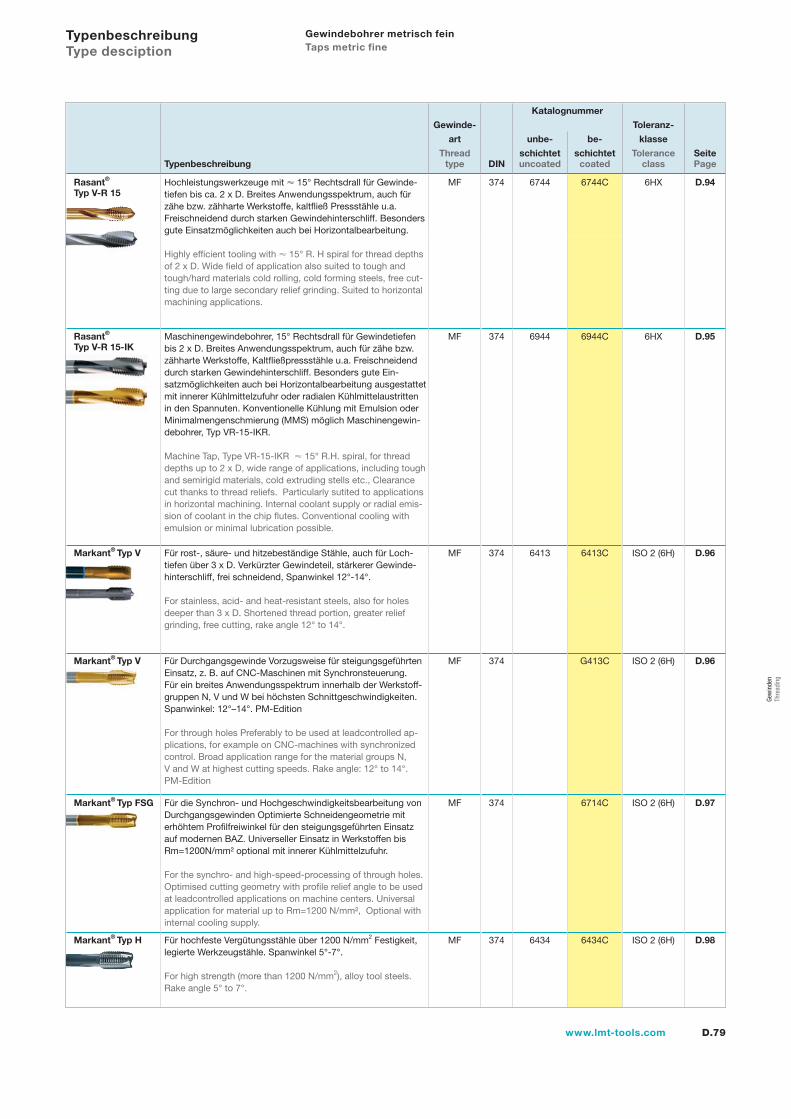
D.79www.lmt-tools.com
Katalognummer
Gewinde- Toleranz-
art unbe- be- klasse
Thread schichtet schichtet Tolerance SeiteTypenbeschreibung type DIN uncoated coated class Page
Rasant®
Typ V-R 15 Hochleistungswerkzeuge mit 15° Rechtsdrall für Gewinde-tiefen bis ca. 2 x D. Breites Anwendungsspektrum, auch für zähe bzw. zähharte Werkstoffe, kaltfließ Pressstähle u.a. Freischneidend durch starken Gewindehinterschliff. Besonders gute Einsatzmöglichkeiten auch bei Horizontalbearbeitung.
Highly efficient tooling with 15° R. H spiral for thread depths of 2 x D. Wide field of application also suited to tough and tough/hard materials cold rolling, cold forming steels, free cut-ting due to large secondary relief grinding. Suited to horizontal machining applications.
MF 374 6744 6744C 6HX D.94
Rasant®
Typ V-R 15-IKMaschinengewindebohrer, 15° Rechtsdrall für Gewindetiefen bis 2 x D. Breites Anwendungsspektrum, auch für zähe bzw. zähharte Werkstoffe, Kaltfließpressstähle u.a. Freischneidend durch starken Gewindehinterschliff. Besonders gute Ein-satzmöglichkeiten auch bei Horizontalbearbeitung ausgestattet mit innerer Kühlmittelzufuhr oder radialen Kühlmittelaustritten in den Spannuten. Konventionelle Kühlung mit Emulsion oder Minimalmengenschmierung (MMS) möglich Maschinengewin-debohrer, Typ VR-15-IKR.
Machine Tap, Type VR-15-IKR 15° R.H. spiral, for thread depths up to 2 x D, wide range of applications, including tough and semirigid materials, cold extruding stells etc., Clearance cut thanks to thread reliefs. Particularly sutited to applications in horizontal machining. Internal coolant supply or radial emis-sion of coolant in the chip flutes. Conventional cooling with emulsion or minimal lubrication possible.
MF 374 6944 6944C 6HX D.95
Markant® Typ V Für rost-, säure- und hitzebeständige Stähle, auch für Loch-tiefen über 3 x D. Verkürzter Gewindeteil, stärkerer Gewinde-hinterschliff, frei schneidend, Spanwinkel 12°-14°.
For stainless, acid- and heat-resistant steels, also for holes deeper than 3 x D. Shortened thread portion, greater relief grinding, free cutting, rake angle 12° to 14°.
MF 374 6413 6413C ISO 2 (6H) D.96
Markant® Typ V Für Durchgangsgewinde Vorzugsweise für steigungsgeführten Einsatz, z. B. auf CNC-Maschinen mit Synchronsteuerung.Für ein breites Anwendungsspektrum innerhalb der Werkstoff-gruppen N, V und W bei höchsten Schnittgeschwindigkeiten. Spanwinkel: 12°–14°. PM-Edition
For through holes Preferably to be used at leadcontrolled ap-plications, for example on CNC-machines with synchronized control. Broad application range for the material groups N, V and W at highest cutting speeds. Rake angle: 12° to 14°. PM-Edition
MF 374 G413C ISO 2 (6H) D.96
Markant® Typ FSG Für die Synchron- und Hochgeschwindigkeitsbearbeitung von Durchgangsgewinden Optimierte Schneidengeometrie mit erhöhtem Profilfreiwinkel für den steigungsgeführten Einsatz auf modernen BAZ. Universeller Einsatz in Werkstoffen bis Rm=1200N/mm² optional mit innerer Kühlmittelzufuhr.
For the synchro- and high-speed-processing of through holes. Optimised cutting geometry with profile relief angle to be used at leadcontrolled applications on machine centers. Universal application for material up to Rm=1200 N/mm², Optional with internal cooling supply.
MF 374 6714C ISO 2 (6H) D.97
Markant® Typ H Für hochfeste Vergütungsstähle über 1200 N/mm2 Festigkeit, legierte Werkzeugstähle. Spanwinkel 5°-7°.
For high strength (more than 1200 N/mm2), alloy tool steels. Rake angle 5° to 7°.
MF 374 6434 6434C ISO 2 (6H) D.98
Typenbeschreibung Type desciption
Gewindebohrer metrisch fein Taps metric fine
Gew
inde
n Th
read
ing
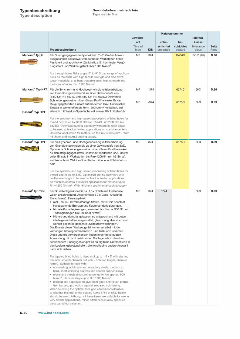
D.80 www.lmt-tools.com
Katalognummer
Gewinde- Toleranz-
art unbe- be- klasse
Thread schichtet schichtet Tolerance SeiteTypenbeschreibung type DIN uncoated coated class Page
Markant® Typ H Für Durchgangsgewinde Spanwinkel: 6°–8° Großer Anwen-dungsbereich bei schwer zerspanbaren Werkstoffen hoher Festigkeit und auch hoher Zähigkeit, z. B. hochfester Vergü-tungsstahl und Werkzeugstahl über 1200 N/mm2.
For through holes Rake angle: 6° to 8° Broad range of applica-tions on materials with high tensile strength and also extra-tough materials, e. g. heat-treatable steel, high strength and tool steel of more than 1200 N/mm2.
MF 374 G434C ISO 2 (6H) D.98
Markant® Typ HPT
Rasant® Typ HPT
Für die Synchron- und Hochgeschwindigkeitsbearbeitung von Grundlochgewinden bis zu einer Gewindetiefe von (3 x D Kat-Nr. 6574C und 2 x D Kat-Nr. 6575C) Optimierte Schneidengeometrie mit erhöhtem Profilfreiwinkel für den steigungsgeführten Einsatz auf modernen BAZ. Universeller Einsatz in Werkstoffen bis Rm=1200N/mm² h6-Schaft, auf Wunsch mit Weldon-Spanfläche mit innerer Kühlmittelzufuhr.
For the synchro- and high-speed-processing of blind holes for thread depths up to (3 x D Cat-No. 6574C und 2 x D Cat-No. 6575C) Optimised cutting geometry with profile relief angle to be used at leadcontrolled applications on machine centers.Universal application for material up to Rm=1200 N/mm². With h6 shank and internal cooling supply.
MF ~374 6574C 6HX D.99
MF ~374 6575C 6HX D.99
Rasant® Typ HPT Für die Synchron- und Hochgeschwindigkeitsbearbeitung von Grundlochgewinden bis zu einer Gewindetiefe von 3 x D.Optimierte Schneidengeometrie mit erhöhtem Profilfreiwinkel für den steigungsgeführten Einsatz auf modernen BAZ. Univer- seller Einsatz in Werkstoffen bis Rm=1200N/mm² h6-Schaft, auf Wunsch mit Weldon-Spanfläche mit innerer Kühlmittelzu-fuhr.
For the synchro- and high-speed-processing of blind holes for thread depths up to 3 x D. Optimised cutting geometry with profile relief angle to be used at leadcontrolled applications on machine centers. Universal application for material up to Rm=1200 N/mm², With h6 shank and internal cooling supply.
MF 374 6576C 6HX D.99
Rasant® Typ Ti Ni Für Grundlochgewinde bis ca. 1.5 x D Tiefe mit Einlauffase, weich anschneidend, Anschnittlänge 2.5 Gang, Anschnitt Einlauffase C. Einsatzgebiet:
rost-, säure-, hitzebeständige Stähle, mittel- bis hochfest.Kurzspanende Bronzen und Kupfersonderlegierungen.Nickel-/Kobaltlegierungen, warmfest bis Rm ca. 900 N/mm2.Titanlegierungen bis Rm 1200 N/mm2.Nitriert und dampfangelassen, so entsprechend mit gutenGleiteigenschaften ausgestattet, gleichzeitig aber auch zumSchutz gegen so genannte „Kaltaufschweißungen“.
Der Einsatz dieser Werkzeuge ist immer sensibel mit den vorherigen Katalognummern 6781 und 6782 abzustimmen. Diese und die vorhergehenden liegen in der bevorzugten Anwendung oft dicht beieinander. Doch gerade in dem be-schriebenem Einzugsgebiet gibt es häufig feine Unterschiede in den Legierungsbestandteilen, die jeweils eine andere Auswahl nach sich ziehen.
For tapping blind holes to depths of up to 1.5 x D with startingchamfer, smooth chamfer cut with 2.5 thread length, chamfer form C. Suitable for use with:
non-rusting, acid-resistant, refractory steels, medium to hard, short-chipping bronzes and special copper alloys.nickel and cobalt alloys, refractory up to Rm approx. 900 N/mm2, titanium alloys up to Rm 1200 N/mm2.nitrided and vaporized to give them good antifriction proper-ties, but also protection against so-called cold fusing.
When selecting the optimal tool, give careful consideration to whether this tool or the catalog items 6781 or 6782 below should be used. Although all these items are suitable for use in very similar applications, minor differences in alloy specifica-tions can affect selection.
•
•
•
•
•
•
MF 374 6774 6HX D.99
Typenbeschreibung Type desciption
Gewindebohrer metrisch fein Taps metric fine
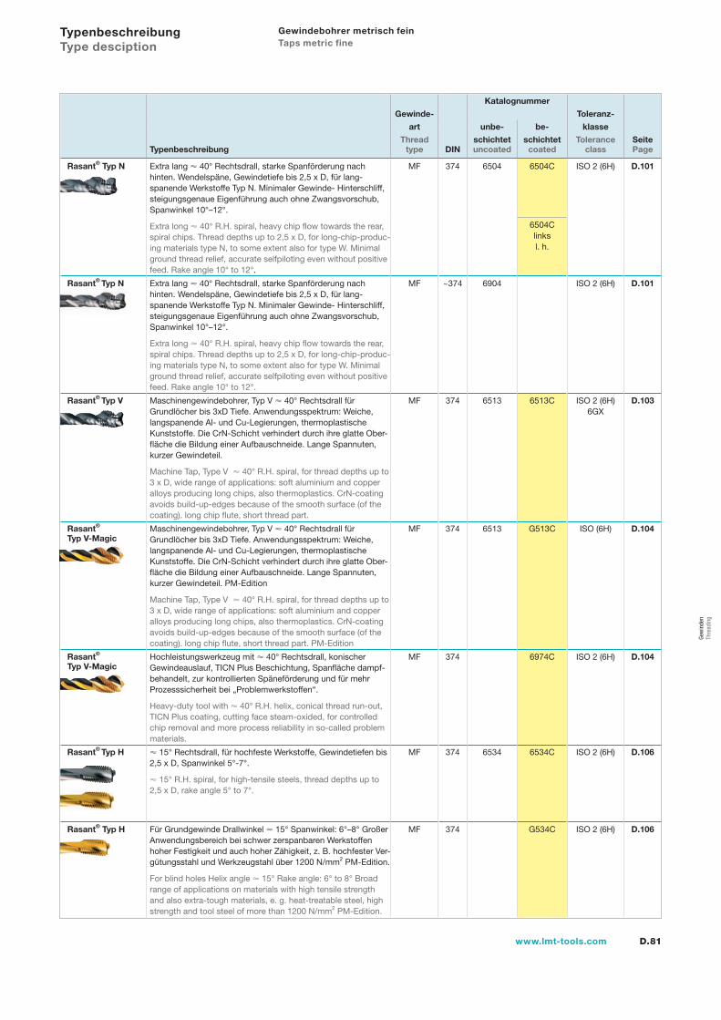
D.81www.lmt-tools.com
Katalognummer
Gewinde- Toleranz-
art unbe- be- klasse
Thread schichtet schichtet Tolerance SeiteTypenbeschreibung type DIN uncoated coated class Page
Rasant® Typ N Extra lang 40° Rechtsdrall, starke Spanförderung nach hinten. Wendelspäne, Gewindetiefe bis 2,5 x D, für lang-spanende Werkstoffe Typ N. Minimaler Gewinde- Hinterschliff, steigungsgenaue Eigenführung auch ohne Zwangsvorschub,Spanwinkel 10°–12°.
Extra long 40° R.H. spiral, heavy chip flow towards the rear, spiral chips. Thread depths up to 2,5 x D, for long-chip-produc-ing materials type N, to some extent also for type W. Minimal ground thread relief, accurate selfpiloting even without positivefeed. Rake angle 10° to 12°.
MF 374 6504 6504C ISO 2 (6H) D.101
6504Clinksl. h.
Rasant® Typ N Extra lang 40° Rechtsdrall, starke Spanförderung nach hinten. Wendelspäne, Gewindetiefe bis 2,5 x D, für lang-spanende Werkstoffe Typ N. Minimaler Gewinde- Hinterschliff, steigungsgenaue Eigenführung auch ohne Zwangsvorschub,Spanwinkel 10°–12°.
Extra long 40° R.H. spiral, heavy chip flow towards the rear, spiral chips. Thread depths up to 2,5 x D, for long-chip-produc-ing materials type N, to some extent also for type W. Minimal ground thread relief, accurate selfpiloting even without positivefeed. Rake angle 10° to 12°.
MF ~374 6904 ISO 2 (6H) D.101
Rasant® Typ V Maschinengewindebohrer, Typ V 40° Rechtsdrall für Grundlöcher bis 3xD Tiefe. Anwendungsspektrum: Weiche, langspanende Al- und Cu-Legierungen, thermoplastische Kunststoffe. Die CrN-Schicht verhindert durch ihre glatte Ober-fläche die Bildung einer Aufbauschneide. Lange Spannuten, kurzer Gewindeteil.
Machine Tap, Type V 40° R.H. spiral, for thread depths up to 3 x D, wide range of applications: soft aluminium and copper alloys producing long chips, also thermoplastics. CrN-coating avoids build-up-edges because of the smooth surface (of the coating). long chip flute, short thread part.
MF 374 6513 6513C ISO 2 (6H)6GX
D.103
Rasant®
Typ V-MagicMaschinengewindebohrer, Typ V 40° Rechtsdrall für Grundlöcher bis 3xD Tiefe. Anwendungsspektrum: Weiche, langspanende Al- und Cu-Legierungen, thermoplastische Kunststoffe. Die CrN-Schicht verhindert durch ihre glatte Ober-fläche die Bildung einer Aufbauschneide. Lange Spannuten, kurzer Gewindeteil. PM-Edition
Machine Tap, Type V 40° R.H. spiral, for thread depths up to 3 x D, wide range of applications: soft aluminium and copper alloys producing long chips, also thermoplastics. CrN-coating avoids build-up-edges because of the smooth surface (of the coating). long chip flute, short thread part. PM-Edition
MF 374 6513 G513C ISO (6H) D.104
Rasant®
Typ V-MagicHochleistungswerkzeug mit 40° Rechtsdrall, konischerGewindeauslauf, TICN Plus Beschichtung, Spanfläche dampf-behandelt, zur kontrollierten Späneförderung und für mehr Prozesssicherheit bei „Problemwerkstoffen“.
Heavy-duty tool with 40° R.H. helix, conical thread run-out, TICN Plus coating, cutting face steam-oxided, for controlled chip removal and more process reliability in so-called problem materials.
MF 374 6974C ISO 2 (6H) D.104
Rasant® Typ H 15° Rechtsdrall, für hochfeste Werkstoffe, Gewindetiefen bis 2,5 x D, Spanwinkel 5°-7°.
15° R.H. spiral, for high-tensile steels, thread depths up to 2,5 x D, rake angle 5° to 7°.
MF 374 6534 6534C ISO 2 (6H) D.106
Rasant® Typ H Für Grundgewinde Drallwinkel 15° Spanwinkel: 6°–8° Großer Anwendungsbereich bei schwer zerspanbaren Werkstoffen hoher Festigkeit und auch hoher Zähigkeit, z. B. hochfester Ver-gütungsstahl und Werkzeugstahl über 1200 N/mm2 PM-Edition.
For blind holes Helix angle 15° Rake angle: 6° to 8° Broad range of applications on materials with high tensile strength and also extra-tough materials, e. g. heat-treatable steel, high strength and tool steel of more than 1200 N/mm2 PM-Edition.
MF 374 G534C ISO 2 (6H) D.106
Typenbeschreibung Type desciption
Gewindebohrer metrisch fein Taps metric fine
Gew
inde
n Th
read
ing
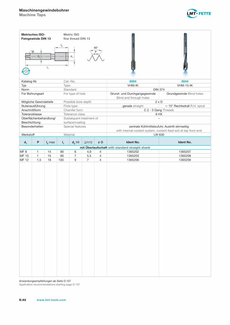
l1
d2
l2
d1
60�
P
D.82 www.lmt-tools.com
Metric ISOfine thread DIN 13
Metrisches ISO-Feingewinde DIN 13
Anwendungsempfehlungen ab Seite D.107Application recommendations starting page D.107
Maschinengewindebohrer Machine Taps
Katalog-Nr. Cat.-No. 6004 6044Typ Type VHM-IK VHM-15-IKNorm Standard DIN 374Für Bohrungsart For type of hole Grund- und Durchgangsgewinde
Blind and through holesGrundgewinde Blind holes
Mögliche Gewindetiefe Possible bore depth 2 x DNutenausführung Flute type gerade straight � 15° Rechtsdrall R.H. spiralAnschnittform Chamfer form C 2 - 3 Gang ThreadsToleranzklasse Tolerance class 6 HXOberflächenbehandlung/Beschichtung
Subsequent treatment of surface/coating
–
Besonderheiten Special features zentrale Kühlmittelzufuhr, Austritt stirnseitigwith internal coolant system, coolant feed exit at tap front end
Werkstoff Material LW 630
d1 P l2 max l1 d2 h9 ❑ h12 z Ident No. Ident No.
mit Überlaufschaft with standard straight shankMF 8 1 14 90 6 4,9 4 1365202 1365207MF 10 1 15 90 7 5,5 4 1365203 1365208MF 12 1,5 18 100 9 7 4 1365206 1365209
gew-082-106.indd 82 14.02.2008 15:57:09
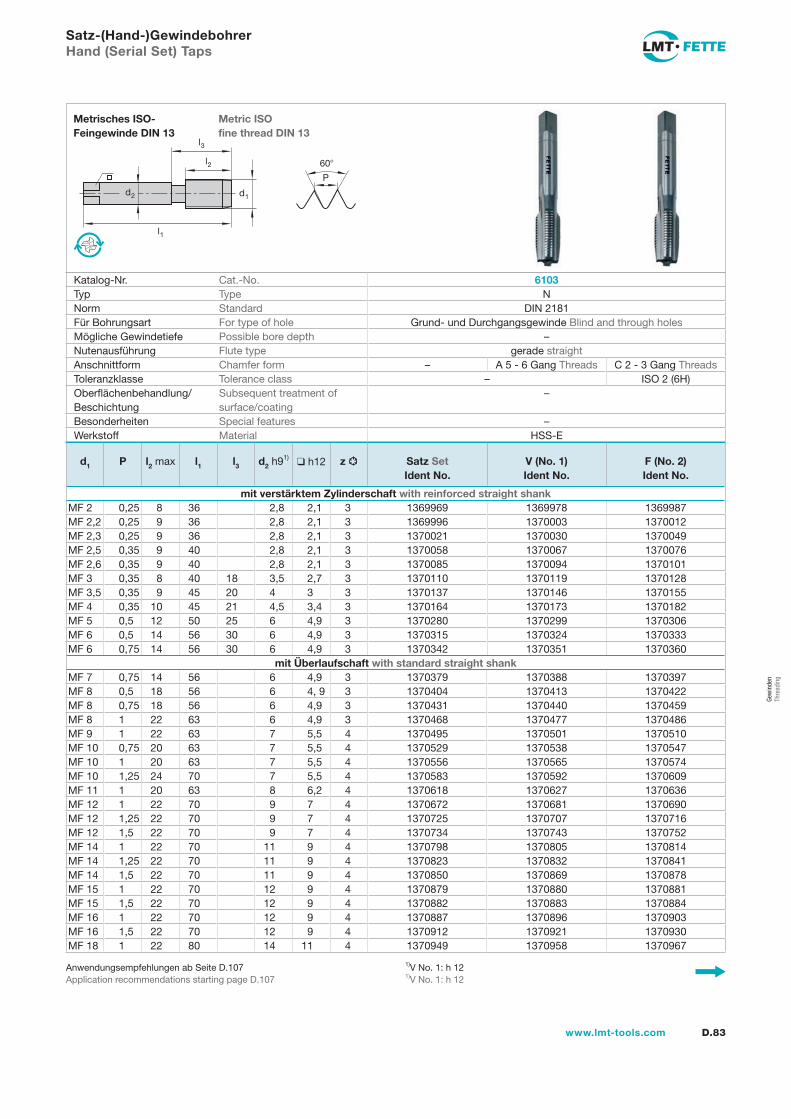
l1
d2
l2
d1
60�
P
l3
D.83www.lmt-tools.com
Metric ISOfine thread DIN 13
Metrisches ISO-Feingewinde DIN 13
1)V No. 1: h 121)V No. 1: h 12
Anwendungsempfehlungen ab Seite D.107Application recommendations starting page D.107
Satz-(Hand-)Gewindebohrer Hand (Serial Set) Taps
Katalog-Nr. Cat.-No. 6103Typ Type NNorm Standard DIN 2181Für Bohrungsart For type of hole Grund- und Durchgangsgewinde Blind and through holesMögliche Gewindetiefe Possible bore depth –Nutenausführung Flute type gerade straightAnschnittform Chamfer form – A 5 - 6 Gang Threads C 2 - 3 Gang ThreadsToleranzklasse Tolerance class – ISO 2 (6H)Oberflächenbehandlung/Beschichtung
Subsequent treatment of surface/coating
–
Besonderheiten Special features –Werkstoff Material HSS-E
d1 P l2 max l1 l3 d2 h91)❑ h12 z Satz Set
Ident No.V (No. 1)Ident No.
F (No. 2)Ident No.
mit verstärktem Zylinderschaft with reinforced straight shankMF 2 0,25 8 36 2,8 2,1 3 1369969 1369978 1369987MF 2,2 0,25 9 36 2,8 2,1 3 1369996 1370003 1370012MF 2,3 0,25 9 36 2,8 2,1 3 1370021 1370030 1370049MF 2,5 0,35 9 40 2,8 2,1 3 1370058 1370067 1370076MF 2,6 0,35 9 40 2,8 2,1 3 1370085 1370094 1370101MF 3 0,35 8 40 18 3,5 2,7 3 1370110 1370119 1370128MF 3,5 0,35 9 45 20 4 3 3 1370137 1370146 1370155MF 4 0,35 10 45 21 4,5 3,4 3 1370164 1370173 1370182MF 5 0,5 12 50 25 6 4,9 3 1370280 1370299 1370306MF 6 0,5 14 56 30 6 4,9 3 1370315 1370324 1370333MF 6 0,75 14 56 30 6 4,9 3 1370342 1370351 1370360
mit Überlaufschaft with standard straight shankMF 7 0,75 14 56 6 4,9 3 1370379 1370388 1370397MF 8 0,5 18 56 6 4, 9 3 1370404 1370413 1370422MF 8 0,75 18 56 6 4,9 3 1370431 1370440 1370459MF 8 1 22 63 6 4,9 3 1370468 1370477 1370486MF 9 1 22 63 7 5,5 4 1370495 1370501 1370510MF 10 0,75 20 63 7 5,5 4 1370529 1370538 1370547MF 10 1 20 63 7 5,5 4 1370556 1370565 1370574MF 10 1,25 24 70 7 5,5 4 1370583 1370592 1370609MF 11 1 20 63 8 6,2 4 1370618 1370627 1370636MF 12 1 22 70 9 7 4 1370672 1370681 1370690MF 12 1,25 22 70 9 7 4 1370725 1370707 1370716MF 12 1,5 22 70 9 7 4 1370734 1370743 1370752MF 14 1 22 70 11 9 4 1370798 1370805 1370814MF 14 1,25 22 70 11 9 4 1370823 1370832 1370841MF 14 1,5 22 70 11 9 4 1370850 1370869 1370878MF 15 1 22 70 12 9 4 1370879 1370880 1370881MF 15 1,5 22 70 12 9 4 1370882 1370883 1370884MF 16 1 22 70 12 9 4 1370887 1370896 1370903MF 16 1,5 22 70 12 9 4 1370912 1370921 1370930MF 18 1 22 80 14 11 4 1370949 1370958 1370967
Gew
inde
nTh
read
ing
gew-082-106.indd 83 14.02.2008 15:57:15
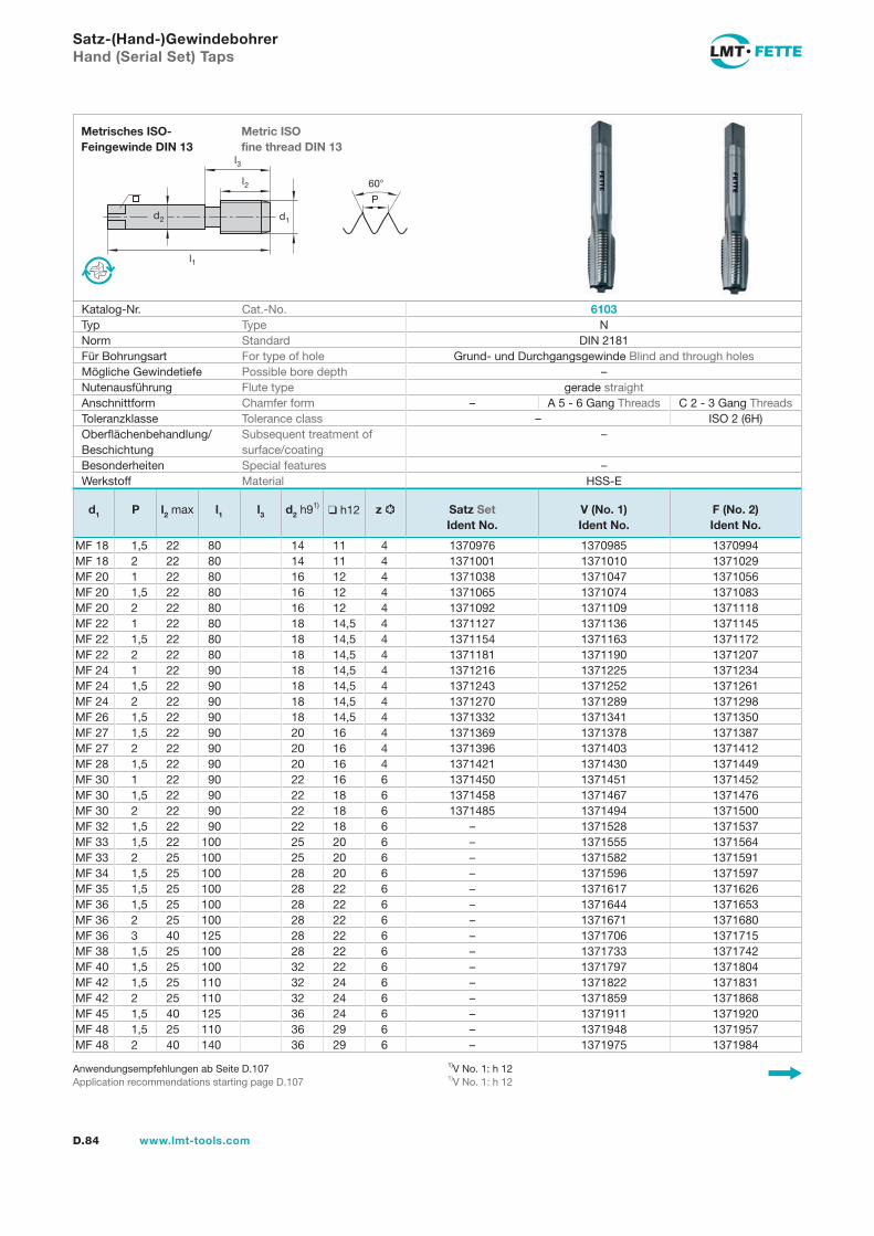
l1
d2
l2
d1
60�
P
l3
D.84 www.lmt-tools.com
Metric ISOfine thread DIN 13
Metrisches ISO-Feingewinde DIN 13
1)V No. 1: h 121)V No. 1: h 12
Anwendungsempfehlungen ab Seite D.107Application recommendations starting page D.107
Satz-(Hand-)Gewindebohrer Hand (Serial Set) Taps
Katalog-Nr. Cat.-No. 6103Typ Type NNorm Standard DIN 2181Für Bohrungsart For type of hole Grund- und Durchgangsgewinde Blind and through holesMögliche Gewindetiefe Possible bore depth –Nutenausführung Flute type gerade straightAnschnittform Chamfer form – A 5 - 6 Gang Threads C 2 - 3 Gang ThreadsToleranzklasse Tolerance class – ISO 2 (6H)Oberflächenbehandlung/Beschichtung
Subsequent treatment of surface/coating
–
Besonderheiten Special features –Werkstoff Material HSS-E
d1 P l2 max l1 l3 d2 h91)❑ h12 z Satz Set
Ident No.V (No. 1)Ident No.
F (No. 2)Ident No.
MF 18 1,5 22 80 14 11 4 1370976 1370985 1370994MF 18 2 22 80 14 11 4 1371001 1371010 1371029MF 20 1 22 80 16 12 4 1371038 1371047 1371056MF 20 1,5 22 80 16 12 4 1371065 1371074 1371083MF 20 2 22 80 16 12 4 1371092 1371109 1371118MF 22 1 22 80 18 14,5 4 1371127 1371136 1371145MF 22 1,5 22 80 18 14,5 4 1371154 1371163 1371172MF 22 2 22 80 18 14,5 4 1371181 1371190 1371207MF 24 1 22 90 18 14,5 4 1371216 1371225 1371234MF 24 1,5 22 90 18 14,5 4 1371243 1371252 1371261MF 24 2 22 90 18 14,5 4 1371270 1371289 1371298MF 26 1,5 22 90 18 14,5 4 1371332 1371341 1371350MF 27 1,5 22 90 20 16 4 1371369 1371378 1371387MF 27 2 22 90 20 16 4 1371396 1371403 1371412MF 28 1,5 22 90 20 16 4 1371421 1371430 1371449MF 30 1 22 90 22 16 6 1371450 1371451 1371452MF 30 1,5 22 90 22 18 6 1371458 1371467 1371476MF 30 2 22 90 22 18 6 1371485 1371494 1371500MF 32 1,5 22 90 22 18 6 – 1371528 1371537MF 33 1,5 22 100 25 20 6 – 1371555 1371564MF 33 2 25 100 25 20 6 – 1371582 1371591MF 34 1,5 25 100 28 20 6 – 1371596 1371597MF 35 1,5 25 100 28 22 6 – 1371617 1371626MF 36 1,5 25 100 28 22 6 – 1371644 1371653MF 36 2 25 100 28 22 6 – 1371671 1371680MF 36 3 40 125 28 22 6 – 1371706 1371715MF 38 1,5 25 100 28 22 6 – 1371733 1371742MF 40 1,5 25 100 32 22 6 – 1371797 1371804MF 42 1,5 25 110 32 24 6 – 1371822 1371831MF 42 2 25 110 32 24 6 – 1371859 1371868MF 45 1,5 40 125 36 24 6 – 1371911 1371920MF 48 1,5 25 110 36 29 6 – 1371948 1371957MF 48 2 40 140 36 29 6 – 1371975 1371984
gew-082-106.indd 84 14.02.2008 15:57:17
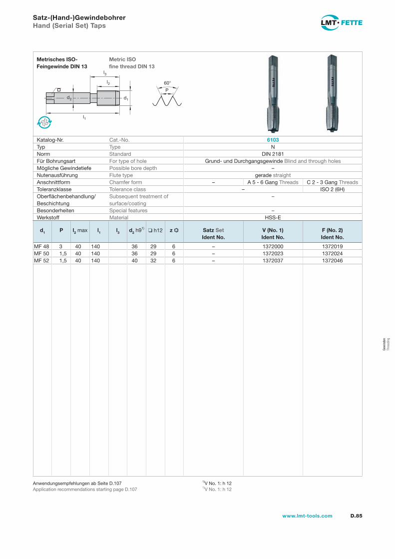
D.85www.lmt-tools.com
Satz-(Hand-)Gewindebohrer Hand (Serial Set) Taps
l1
d2
l2
d1
60�
P
l3
Metric ISOfine thread DIN 13
Metrisches ISO-Feingewinde DIN 13
Katalog-Nr. Cat.-No. 6103Typ Type NNorm Standard DIN 2181Für Bohrungsart For type of hole Grund- und Durchgangsgewinde Blind and through holesMögliche Gewindetiefe Possible bore depth –Nutenausführung Flute type gerade straightAnschnittform Chamfer form – A 5 - 6 Gang Threads C 2 - 3 Gang ThreadsToleranzklasse Tolerance class – ISO 2 (6H)Oberflächenbehandlung/Beschichtung
Subsequent treatment of surface/coating
–
Besonderheiten Special features –Werkstoff Material HSS-E
1)V No. 1: h 121)V No. 1: h 12
Anwendungsempfehlungen ab Seite D.107Application recommendations starting page D.107
d1 P l2 max l1 l3 d2 h91)❑ h12 z Satz Set
Ident No.V (No. 1)Ident No.
F (No. 2)Ident No.
MF 48 3 40 140 36 29 6 – 1372000 1372019MF 50 1,5 40 140 36 29 6 – 1372023 1372024MF 52 1,5 40 140 40 32 6 – 1372037 1372046
Gew
inde
nTh
read
ing
gew-082-106.indd 85 14.02.2008 15:57:19
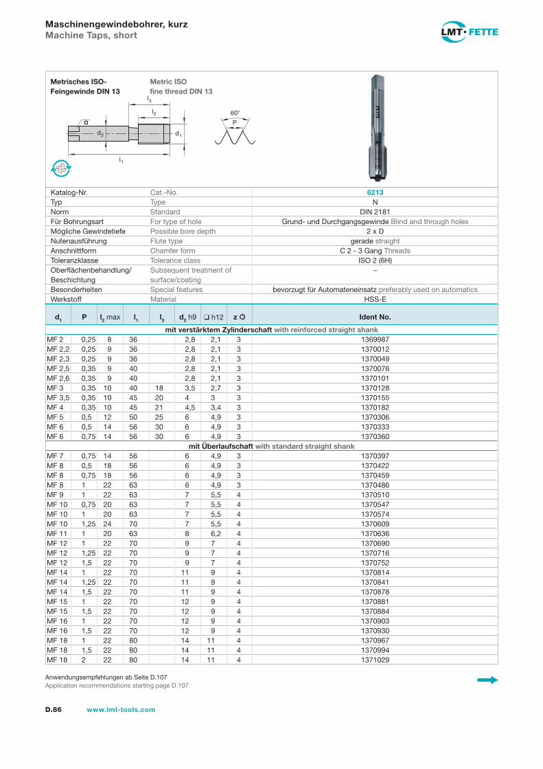
l1
d2
l2
d1
60�
P
l3
D.86 www.lmt-tools.com
Metric ISOfine thread DIN 13
Metrisches ISO-Feingewinde DIN 13
Anwendungsempfehlungen ab Seite D.107Application recommendations starting page D.107
Maschinengewindebohrer, kurz Machine Taps, short
Katalog-Nr. Cat.-No. 6213Typ Type NNorm Standard DIN 2181Für Bohrungsart For type of hole Grund- und Durchgangsgewinde Blind and through holesMögliche Gewindetiefe Possible bore depth 2 x DNutenausführung Flute type gerade straightAnschnittform Chamfer form C 2 - 3 Gang ThreadsToleranzklasse Tolerance class ISO 2 (6H)Oberflächenbehandlung/Beschichtung
Subsequent treatment of surface/coating
–
Besonderheiten Special features bevorzugt für Automateneinsatz preferably used on automaticsWerkstoff Material HSS-E
d1 P l2 max l1 l3 d2 h9 ❑ h12 z Ident No.
mit verstärktem Zylinderschaft with reinforced straight shankMF 2 0,25 8 36 2,8 2,1 3 1369987MF 2,2 0,25 9 36 2,8 2,1 3 1370012MF 2,3 0,25 9 36 2,8 2,1 3 1370049MF 2,5 0,35 9 40 2,8 2,1 3 1370076MF 2,6 0,35 9 40 2,8 2,1 3 1370101MF 3 0,35 10 40 18 3,5 2,7 3 1370128MF 3,5 0,35 10 45 20 4 3 3 1370155MF 4 0,35 10 45 21 4,5 3,4 3 1370182MF 5 0,5 12 50 25 6 4,9 3 1370306MF 6 0,5 14 56 30 6 4,9 3 1370333MF 6 0,75 14 56 30 6 4,9 3 1370360
mit Überlaufschaft with standard straight shankMF 7 0,75 14 56 6 4,9 3 1370397MF 8 0,5 18 56 6 4,9 3 1370422MF 8 0,75 18 56 6 4,9 3 1370459MF 8 1 22 63 6 4,9 3 1370486MF 9 1 22 63 7 5,5 4 1370510MF 10 0,75 20 63 7 5,5 4 1370547MF 10 1 20 63 7 5,5 4 1370574MF 10 1,25 24 70 7 5,5 4 1370609MF 11 1 20 63 8 6,2 4 1370636MF 12 1 22 70 9 7 4 1370690MF 12 1,25 22 70 9 7 4 1370716MF 12 1,5 22 70 9 7 4 1370752MF 14 1 22 70 11 9 4 1370814MF 14 1,25 22 70 11 9 4 1370841MF 14 1,5 22 70 11 9 4 1370878MF 15 1 22 70 12 9 4 1370881MF 15 1,5 22 70 12 9 4 1370884MF 16 1 22 70 12 9 4 1370903MF 16 1,5 22 70 12 9 4 1370930MF 18 1 22 80 14 11 4 1370967MF 18 1,5 22 80 14 11 4 1370994MF 18 2 22 80 14 11 4 1371029
gew-082-106.indd 86 14.02.2008 15:57:21
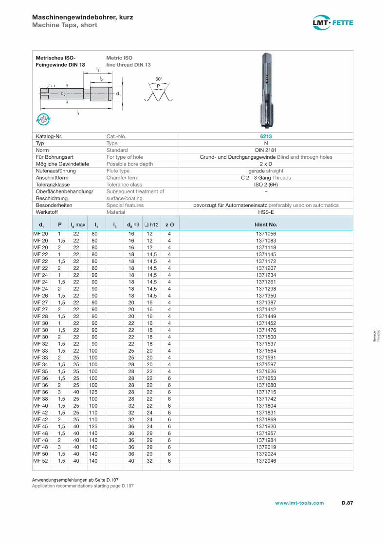
l1
d2
l2
d1
60�
P
l3
D.87www.lmt-tools.com
Metric ISOfine thread DIN 13
Metrisches ISO-Feingewinde DIN 13
Anwendungsempfehlungen ab Seite D.107Application recommendations starting page D.107
Maschinengewindebohrer, kurz Machine Taps, short
Katalog-Nr. Cat.-No. 6213Typ Type NNorm Standard DIN 2181Für Bohrungsart For type of hole Grund- und Durchgangsgewinde Blind and through holesMögliche Gewindetiefe Possible bore depth 2 x DNutenausführung Flute type gerade straightAnschnittform Chamfer form C 2 - 3 Gang ThreadsToleranzklasse Tolerance class ISO 2 (6H)Oberflächenbehandlung/Beschichtung
Subsequent treatment of surface/coating
–
Besonderheiten Special features bevorzugt für Automateneinsatz preferably used on automaticsWerkstoff Material HSS-E
d1 P l2 max l1 l3 d2 h9 ❑ h12 z Ident No.
MF 20 1 22 80 16 12 4 1371056MF 20 1,5 22 80 16 12 4 1371083MF 20 2 22 80 16 12 4 1371118MF 22 1 22 80 18 14,5 4 1371145MF 22 1,5 22 80 18 14,5 4 1371172MF 22 2 22 80 18 14,5 4 1371207MF 24 1 22 90 18 14,5 4 1371234MF 24 1,5 22 90 18 14,5 4 1371261MF 24 2 22 90 18 14,5 4 1371298MF 26 1,5 22 90 18 14,5 4 1371350MF 27 1,5 22 90 20 16 4 1371387MF 27 2 22 90 20 16 4 1371412MF 28 1,5 22 90 20 16 4 1371449MF 30 1 22 90 22 16 4 1371452MF 30 1,5 22 90 22 18 4 1371476MF 30 2 22 90 22 18 4 1371500MF 32 1,5 22 90 22 18 4 1371537MF 33 1,5 22 100 25 20 4 1371564MF 33 2 25 100 25 20 4 1371591MF 34 1,5 25 100 28 20 4 1371597MF 35 1,5 25 100 28 22 4 1371626MF 36 1,5 25 100 28 22 6 1371653MF 36 2 25 100 28 22 6 1371680MF 36 3 40 125 28 22 6 1371715MF 38 1,5 25 100 28 22 6 1371742MF 40 1,5 25 100 32 22 6 1371804MF 42 1,5 25 110 32 24 6 1371831MF 42 2 25 110 32 24 6 1371868MF 45 1,5 40 125 36 24 6 1371920MF 48 1,5 40 140 36 29 6 1371957MF 48 2 40 140 36 29 6 1371984MF 48 3 40 140 36 29 6 1372019MF 50 1,5 40 140 36 29 6 1372024MF 52 1,5 40 140 40 32 6 1372046
Gew
inde
nTh
read
ing
gew-082-106.indd 87 14.02.2008 15:57:22
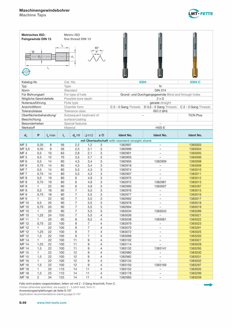
l1
d2
l2
d1
60�
P
D.88 www.lmt-tools.com
Metric ISOfine thread DIN 13
Metrisches ISO-Feingewinde DIN 13
Falls nicht anders vorgeschrieben, liefern wir mit 2 - 3 Gang-Anschnitt, Form C.Unless otherwise specified, we supply 2 - 3 pitch lead, form C.Anwendungsempfehlungen ab Seite D.107Application recommendations starting page D.107
Maschinengewindebohrer Machine Taps
Katalog-Nr. Cat.-No. 6304 6304 CTyp Type NNorm Standard DIN 374Für Bohrungsart For type of hole Grund- und Durchgangsgewinde Blind and through holesMögliche Gewindetiefe Possible bore depth 2 x DNutenausführung Flute type gerade straightAnschnittform Chamfer form C 2 - 3 Gang Threads D 3,5 - 5 Gang Threads C 2 - 3 Gang ThreadsToleranzklasse Tolerance class ISO 2 (6H)Oberflächenbehandlung/Beschichtung
Subsequent treatment of surface/coating
– TiCN Plus
Besonderheiten Special features –Werkstoff Material HSS-E
d1 P l2 max l1 d2 h9 ❑ h12 z Ident No. Ident No. Ident No.
mit Überlaufschaft with standard straight shankMF 3 0,35 8 56 2,2 1,2 3 1382897 – 1383003MF 3,5 0,35 9 56 2,5 2,1 3 1382899 – 1383004MF 4 0,5 10 63 2,8 2,1 3 1382901 – 1383005MF 5 0,5 12 70 3,5 2,7 3 1382903 – 1383006MF 6 0,5 14 80 4,5 3,4 3 1382905 1382909 1383008MF 6 0,75 14 80 4,5 3,4 3 1382918 – 1383009MF 7 0,5 14 80 5,5 4,3 3 1382974 – 1383010MF 7 0,75 14 80 5,5 4,3 3 1382907 – 1383011MF 8 0,5 19 80 6 4,9 3 1382975 – 1383012MF 8 0,75 19 80 6 4,9 3 1382972 1382981 1383013MF 8 1 22 90 6 4,9 3 1382990 1383007 1383287MF 9 0,5 18 80 7 5,5 3 1382976 – 1383015MF 9 0,75 18 80 7 5,5 3 1382977 – 1383016MF 9 1 22 90 7 5,5 3 1382992 – 1383017MF 10 0,5 20 90 7 5,5 3 1382978 – 1383018MF 10 0,75 20 90 7 5,5 3 1382994 – 1383019MF 10 1 20 90 7 5,5 3 1383034 1383043 1383289MF 10 1,25 24 100 7 5,5 4 1383036 – 1383021MF 11 1 20 90 8 6,2 4 1383038 1383061 1383022MF 12 0,75 22 100 9 7 4 1382979 – 1383023MF 12 1 22 100 9 7 4 1383070 – 1383291MF 12 1,25 22 100 9 7 4 1383072 – 1383025MF 12 1,5 22 100 9 7 4 1383098 – 1383293MF 14 1 22 100 11 9 4 1383102 – 1383027MF 14 1,25 22 100 11 9 4 1383114 – 1383028MF 14 1,5 22 100 11 9 4 1383132 1383141 1383295MF 15 1 22 100 12 9 4 1382980 – 1383030MF 15 1,5 22 100 12 9 4 1382982 – 1383031MF 16 1 22 100 12 9 4 1383134 – 1383032MF 16 1,5 22 100 12 9 4 1383150 1383169 1383297MF 18 1 25 110 14 11 4 1383152 – 1383035MF 18 1,5 25 110 14 11 4 1383178 – 1383299MF 18 2 34 125 14 11 4 1382983 – 1383039
gew-082-106.indd 88 14.02.2008 15:57:23
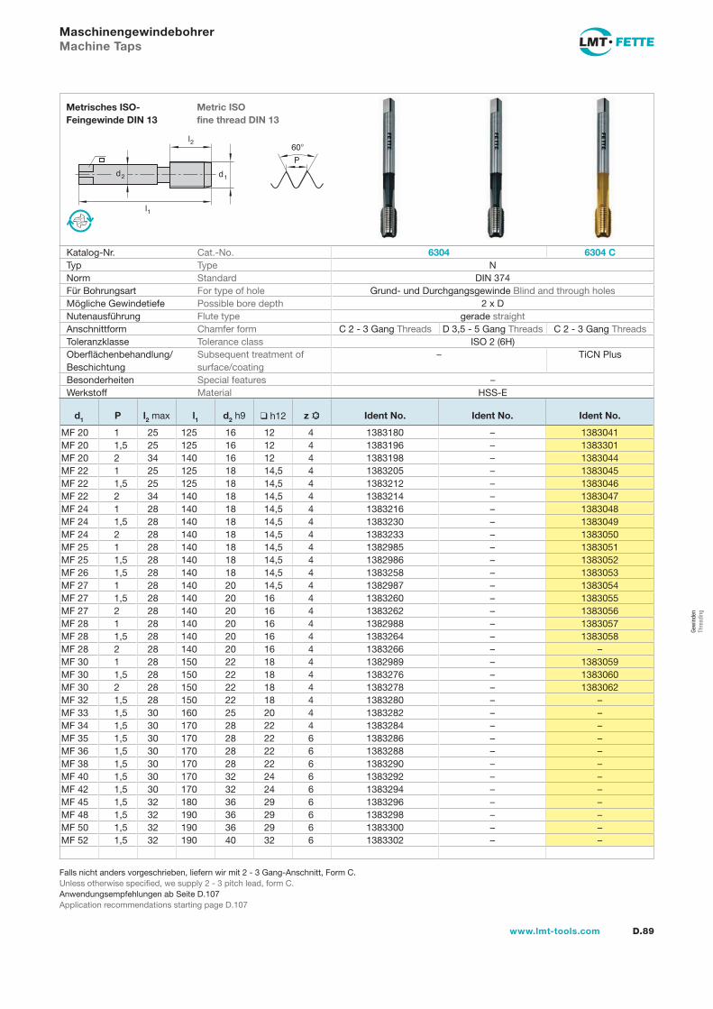
l1
d2
l2
d1
60�
P
D.89www.lmt-tools.com
Metric ISOfine thread DIN 13
Metrisches ISO-Feingewinde DIN 13
Falls nicht anders vorgeschrieben, liefern wir mit 2 - 3 Gang-Anschnitt, Form C.Unless otherwise specified, we supply 2 - 3 pitch lead, form C.Anwendungsempfehlungen ab Seite D.107Application recommendations starting page D.107
Maschinengewindebohrer Machine Taps
Katalog-Nr. Cat.-No. 6304 6304 CTyp Type NNorm Standard DIN 374Für Bohrungsart For type of hole Grund- und Durchgangsgewinde Blind and through holesMögliche Gewindetiefe Possible bore depth 2 x DNutenausführung Flute type gerade straightAnschnittform Chamfer form C 2 - 3 Gang Threads D 3,5 - 5 Gang Threads C 2 - 3 Gang ThreadsToleranzklasse Tolerance class ISO 2 (6H)Oberflächenbehandlung/Beschichtung
Subsequent treatment of surface/coating
– TiCN Plus
Besonderheiten Special features –Werkstoff Material HSS-E
d1 P l2 max l1 d2 h9 ❑ h12 z Ident No. Ident No. Ident No.
MF 20 1 25 125 16 12 4 1383180 – 1383041MF 20 1,5 25 125 16 12 4 1383196 – 1383301MF 20 2 34 140 16 12 4 1383198 – 1383044MF 22 1 25 125 18 14,5 4 1383205 – 1383045MF 22 1,5 25 125 18 14,5 4 1383212 – 1383046MF 22 2 34 140 18 14,5 4 1383214 – 1383047MF 24 1 28 140 18 14,5 4 1383216 – 1383048MF 24 1,5 28 140 18 14,5 4 1383230 – 1383049MF 24 2 28 140 18 14,5 4 1383233 – 1383050MF 25 1 28 140 18 14,5 4 1382985 – 1383051MF 25 1,5 28 140 18 14,5 4 1382986 – 1383052MF 26 1,5 28 140 18 14,5 4 1383258 – 1383053MF 27 1 28 140 20 14,5 4 1382987 – 1383054MF 27 1,5 28 140 20 16 4 1383260 – 1383055MF 27 2 28 140 20 16 4 1383262 – 1383056MF 28 1 28 140 20 16 4 1382988 – 1383057MF 28 1,5 28 140 20 16 4 1383264 – 1383058MF 28 2 28 140 20 16 4 1383266 – –MF 30 1 28 150 22 18 4 1382989 – 1383059MF 30 1,5 28 150 22 18 4 1383276 – 1383060MF 30 2 28 150 22 18 4 1383278 – 1383062MF 32 1,5 28 150 22 18 4 1383280 – –MF 33 1,5 30 160 25 20 4 1383282 – –MF 34 1,5 30 170 28 22 4 1383284 – –MF 35 1,5 30 170 28 22 6 1383286 – –MF 36 1,5 30 170 28 22 6 1383288 – –MF 38 1,5 30 170 28 22 6 1383290 – –MF 40 1,5 30 170 32 24 6 1383292 – –MF 42 1,5 30 170 32 24 6 1383294 – –MF 45 1,5 32 180 36 29 6 1383296 – –MF 48 1,5 32 190 36 29 6 1383298 – –MF 50 1,5 32 190 36 29 6 1383300 – –MF 52 1,5 32 190 40 32 6 1383302 – –
Gew
inde
nTh
read
ing
gew-082-106.indd 89 14.02.2008 15:57:25
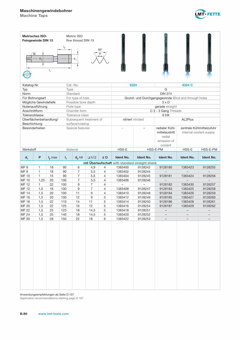
l1
d2
l2
d1
60�
P
D.90 www.lmt-tools.com
Metric ISOfine thread DIN 13
Metrisches ISO-Feingewinde DIN 13
Anwendungsempfehlungen ab Seite D.107Application recommendations starting page D.107
Maschinengewindebohrer Machine Taps
Katalog-Nr. Cat.-No. 6324 6324 CTyp Type GNorm Standard DIN 374Für Bohrungsart For type of hole Grund- und Durchgangsgewinde Blind and through holesMögliche Gewindetiefe Possible bore depth 3 x DNutenausführung Flute type gerade straightAnschnittform Chamfer form C 2 - 3 Gang ThreadsToleranzklasse Tolerance class 6 HXOberflächenbehandlung/Beschichtung
Subsequent treatment of surface/coating
nitriert nitrided AL2Plus
Besonderheiten Special features - – radialer Kühl-mittelaustritt
radialemission of
coolant
zentrale Kühlmittelzufuhr internal coolant supply
Werkstoff Material HSS-E HSS-E-PM HSS-E HSS-E-PM
d1 P l2 max l1 d2 h9 ❑ h12 z Ident No. Ident No. Ident No. Ident No. Ident No.
mit Überlaufschaft with standard straight shankMF 8 1 18 90 6 4,9 4 1383400 9128242 9128180 1383423 9128255MF 9 1 18 90 7 5,5 4 1383402 9128244 – – –MF 10 1 15 90 7 5,5 4 1383404 9128245 9128181 1383424 9128256MF 10 1,25 20 100 7 5,5 4 1383406 9128246 – – –MF 12 1 22 100 9 7 4 – – 9128182 1383430 9128257MF 12 1,5 18 100 9 7 4 1383408 9128247 9128183 1383425 9128258MF 14 1,5 20 100 11 9 4 1383410 9128248 9128184 1383426 9128259MF 16 1,5 20 100 12 9 5 1383412 9128249 9128185 1383427 9128260MF 18 1,5 22 110 14 11 5 1383414 9128250 9128186 1383428 9128261MF 20 1,5 22 125 16 12 5 1383416 9128254 9128187 1383429 9128262MF 22 1,5 25 125 18 14,5 5 1383418 9128251 – – –MF 24 1,5 25 140 18 14,5 5 1383420 9128252 – – –MF 30 1,5 28 150 22 18 6 1383422 9128253 – – –
gew-082-106.indd 90 25.02.2008 11:09:23
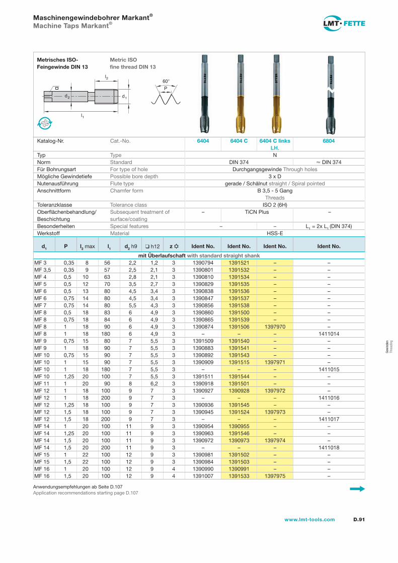
l1
d2
l2
d1
60�
P
D.91www.lmt-tools.com
Metric ISOfine thread DIN 13
Metrisches ISO-Feingewinde DIN 13
Anwendungsempfehlungen ab Seite D.107Application recommendations starting page D.107
Maschinengewindebohrer Markant® Machine Taps Markant®
Katalog-Nr. Cat.-No. 6404 6404 C 6404 C links LH.
6804
Typ Type NNorm Standard DIN 374 � DIN 374Für Bohrungsart For type of hole Durchgangsgewinde Through holesMögliche Gewindetiefe Possible bore depth 3 x DNutenausführung Flute type gerade / Schälnut straight / Spiral pointedAnschnittform Chamfer form B 3,5 - 5 Gang
ThreadsToleranzklasse Tolerance class ISO 2 (6H)Oberflächenbehandlung/Beschichtung
Subsequent treatment of surface/coating
– TiCN Plus –
Besonderheiten Special features – – L1 = 2x L1 (DIN 374)Werkstoff Material HSS-E
d1 P l2 max l1 d2 h9 ❑ h12 z Ident No. Ident No. Ident No. Ident No.
mit Überlaufschaft with standard straight shankMF 3 0,35 8 56 2,2 1,2 3 1390794 1391521 – –MF 3,5 0,35 9 57 2,5 2,1 3 1390801 1391532 – –MF 4 0,5 10 63 2,8 2,1 3 1390810 1391534 – –MF 5 0,5 12 70 3,5 2,7 3 1390829 1391535 – –MF 6 0,5 13 80 4,5 3,4 3 1390838 1391536 – –MF 6 0,75 14 80 4,5 3,4 3 1390847 1391537 – –MF 7 0,75 14 80 5,5 4,3 3 1390856 1391538 – –MF 8 0,5 18 83 6 4,9 3 1390860 1391500 – –MF 8 0,75 18 84 6 4,9 3 1390865 1391539 – –MF 8 1 18 90 6 4,9 3 1390874 1391506 1397970 –MF 8 1 18 180 6 4,9 3 – – – 1411014MF 9 0,75 15 80 7 5,5 3 1391509 1391540 – –MF 9 1 18 90 7 5,5 3 1390883 1391541 – –MF 10 0,75 15 90 7 5,5 3 1390892 1391543 – –MF 10 1 15 90 7 5,5 3 1390909 1391515 1397971 –MF 10 1 18 180 7 5,5 3 – – – 1411015MF 10 1,25 20 100 7 5,5 3 1391511 1391544 – –MF 11 1 20 90 8 6,2 3 1390918 1391501 – –MF 12 1 18 100 9 7 3 1390927 1390928 1397972 –MF 12 1 18 200 9 7 3 – – – 1411016MF 12 1,25 18 100 9 7 3 1390936 1391545 – –MF 12 1,5 18 100 9 7 3 1390945 1391524 1397973 –MF 12 1,5 18 200 9 7 3 – – – 1411017MF 14 1 20 100 11 9 3 1390954 1390955 – –MF 14 1,25 20 100 11 9 3 1390963 1391546 – –MF 14 1,5 20 100 11 9 3 1390972 1390973 1397974 –MF 14 1,5 20 200 11 9 3 – – – 1411018MF 15 1 22 100 12 9 3 1390981 1391502 – –MF 15 1,5 22 100 12 9 3 1390984 1391503 – –MF 16 1 20 100 12 9 4 1390990 1390991 – –MF 16 1,5 20 100 12 9 4 1391007 1391533 1397975 –
Gew
inde
nTh
read
ing
gew-082-106.indd 91 14.02.2008 15:57:35
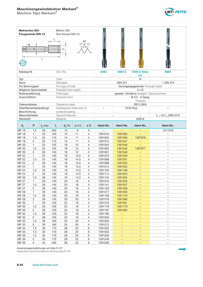
D.92 www.lmt-tools.com
Anwendungsempfehlungen ab Seite D.107Application recommendations starting page D.107
l1
d2
l2
d1
60�
P
Metric ISOfine thread DIN 13
Metrisches ISO-Feingewinde DIN 13
Maschinengewindebohrer Markant® Machine Taps Markant®
Katalog-Nr. Cat.-No. 6404 6404 C 6404 C links LH.
6804
Typ Type NNorm Standard DIN 374 � DIN 374Für Bohrungsart For type of hole Durchgangsgewinde Through holesMögliche Gewindetiefe Possible bore depth 3 x DNutenausführung Flute type gerade / Schälnut straight / Spiral pointedAnschnittform Chamfer form B 3,5 - 5 Gang
ThreadsToleranzklasse Tolerance class ISO 2 (6H)Oberflächenbehandlung/Beschichtung
Subsequent treatment of surface/coating
– TiCN Plus –
Besonderheiten Special features – – L1 = 2x L1 (DIN 374)Werkstoff Material HSS-E
d1 P l2 max l1 d2 h9 ❑ h12 z Ident No. Ident No. Ident No. Ident No.
MF 16 1,5 20 200 12 9 4 – – – 1411019MF 18 1 22 100 14 11 4 1391016 1391563 – –MF 18 1,5 22 110 14 11 4 1391025 1391026 1397976 –MF 18 2 22 110 14 11 4 1391512 1391547 – –MF 20 1 22 125 16 12 4 1391043 1391548 – –MF 20 1,5 22 125 16 12 4 1391052 1391542 1397977 –MF 20 2 28 140 16 12 4 1391061 1391549 – –MF 22 1 25 140 18 14,5 4 1391070 1391550 – –MF 22 1,5 25 140 18 14,5 4 1391089 1391551 – –MF 22 2 28 140 18 14,5 4 1391098 1391552 – –MF 24 1 25 140 18 14,5 4 1391514 1391553 – –MF 24 1,5 25 140 18 14,5 4 1391105 1391106 – –MF 24 2 25 140 18 14,5 4 1391114 1391554 – –MF 26 1,5 28 140 18 14,5 4 1391132 1391555 – –MF 27 1 28 140 20 16 4 1391516 1391556 – –MF 27 1,5 28 140 20 16 4 1391141 1391557 – –MF 27 2 28 140 20 16 4 1391150 1391558 – –MF 28 1 28 140 20 16 4 1391517 1391559 – –MF 28 1,5 28 140 20 16 4 1391169 1391170 – –MF 28 2 28 140 20 20 4 1391518 1391560 – –MF 30 1 28 150 22 18 4 1391519 1391561 – –MF 30 1,5 28 150 22 18 4 1391178 1391179 – –MF 30 2 28 150 22 18 4 1391187 1391562 – –MF 32 1,5 28 150 22 18 4 1391196 – – –MF 32 2 28 150 22 18 4 1391520 – – –MF 33 1,5 30 160 25 20 4 1391203 – – –MF 33 2 30 160 25 20 4 1391212 – – –MF 34 1,5 30 170 28 22 6 1391522 – – –MF 35 1,5 30 170 28 22 6 1391523 – – –MF 36 1,5 30 170 28 22 6 1391230 – – –MF 36 2 30 170 28 22 6 1391249 – – –MF 36 3 42 200 28 22 6 1391258 – – –
gew-082-106.indd 92 14.02.2008 15:57:38
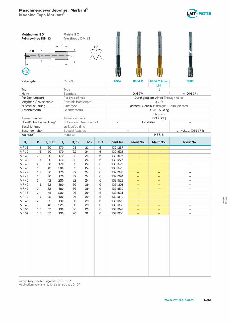
D.93www.lmt-tools.com
Anwendungsempfehlungen ab Seite D.107Application recommendations starting page D.107
l1
d2
l2
d1
60�
P
Metric ISOfine thread DIN 13
Metrisches ISO-Feingewinde DIN 13
Maschinengewindebohrer Markant® Machine Taps Markant®
Katalog-Nr. Cat.-No. 6404 6404 C 6404 C links LH.
6804
Typ Type NNorm Standard DIN 374 � DIN 374Für Bohrungsart For type of hole Durchgangsgewinde Through holesMögliche Gewindetiefe Possible bore depth 3 x DNutenausführung Flute type gerade / Schälnut straight / Spiral pointedAnschnittform Chamfer form B 3,5 - 5 Gang
ThreadsToleranzklasse Tolerance class ISO 2 (6H)Oberflächenbehandlung/Beschichtung
Subsequent treatment of surface/coating
– TiCN Plus –
Besonderheiten Special features – – L1 = 2x L1 (DIN 374)Werkstoff Material HSS-E
d1 P l2 max l1 d2 h9 ❑ h12 z Ident No. Ident No. Ident No. Ident No.
MF 38 1,5 30 170 28 22 6 1391267 – – –MF 39 1,5 30 170 32 24 6 1391525 – – –MF 39 2 30 170 32 24 6 1391526 – – –MF 40 1,5 30 170 32 24 6 1391276 – – –MF 40 2 30 170 32 24 6 1391527 – – –MF 40 3 42 200 32 24 6 1391528 – – –MF 42 1,5 30 170 32 24 6 1391285 – – –MF 42 2 30 170 32 24 6 1391294 – – –MF 42 3 42 200 32 24 6 1391529 – – –MF 45 1,5 32 180 36 29 6 1391301 – – –MF 45 2 32 180 36 29 6 1391530 – – –MF 45 3 48 200 36 29 6 1391531 – – –MF 48 1,5 32 190 36 29 6 1391310 – – –MF 48 2 32 190 36 29 6 1391329 – – –MF 48 3 48 225 36 29 6 1391338 – – –MF 50 1,5 32 190 36 29 6 1391347 – – –MF 52 1,5 32 190 40 32 6 1391356 – – –
Gew
inde
nTh
read
ing
gew-082-106.indd 93 14.02.2008 15:57:42
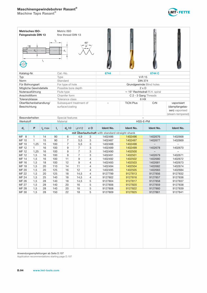
l1
d2
l2
d1
60�
P
D.94 www.lmt-tools.com
Metric ISOfine thread DIN 13
Metrisches ISO-Feingewinde DIN 13
Anwendungsempfehlungen ab Seite D.107Application recommendations starting page D.107
Maschinengewindebohrer Rasant®
Machine Taps Rasant®
Katalog-Nr. Cat.-No. 6744 6744 CTyp Type V-R 15Norm Standard DIN 374Für Bohrungsart For type of hole Grundgewinde Blind holesMögliche Gewindetiefe Possible bore depth 2 x DNutenausführung Flute type � 15° Rechtsdrall R.H. spiralAnschnittform Chamfer form C 2 - 3 Gang ThreadsToleranzklasse Tolerance class 6 HXOberflächenbehandlung/Beschichtung
Subsequent treatment of surface/coating
– TiCN Plus CrN vaporisiert (dampfangelas-sen) vaporised
(steam-tempered)Besonderheiten Special features –Werkstoff Material HSS-E-PM
d1 P l2 max l1 d2 h9 ❑ h12 z Ident No. Ident No. Ident No. Ident No.
mit Überlaufschaft with standard straight shankMF 8 1 14 90 6 4,9 3 1402486 1402496 1402676 1402668MF 10 1 15 90 7 5,5 3 1402487 1402497 1402677 1402669MF 10 1,25 15 100 7 5,5 3 1402488 1402498 – –MF 12 1 16 100 9 7 3 1402489 1402499 1402678 1402670MF 12 1,25 16 100 9 7 3 1402490 1402500 – –MF 12 1,5 16 100 9 7 3 1402491 1402501 1402679 1402671MF 14 1,5 16 100 11 9 4 1402492 1402502 1402680 1402672MF 16 1,5 18 100 12 9 4 1402493 1402503 1402681 1402673MF 18 1,5 20 110 14 11 4 1402494 1402504 1402682 1402674MF 20 1,5 20 125 16 12 4 1402495 1402505 1402683 1402684MF 22 1,5 20 125 18 14,5 4 9127799 9127813 9127856 9127832MF 24 1,5 25 140 18 14,5 4 9127802 9127816 9127857 9127836MF 26 1,5 28 140 18 14,5 5 9127804 9127817 9127858 9127837MF 27 1,5 28 140 20 16 5 9127806 9127820 9127859 9127838MF 28 1,5 28 140 20 16 5 9127808 9127822 9127860 9127839MF 30 1,5 28 150 22 18 5 9127809 9127825 9127861 9127841
gew-082-106.indd 94 14.02.2008 15:57:45
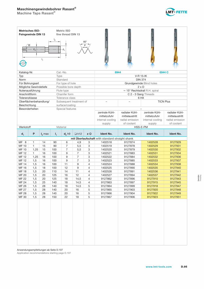
l1
d2
l2
d1
60�
P
D.95www.lmt-tools.com
Metric ISOfine thread DIN 13
Metrisches ISO-Feingewinde DIN 13
Anwendungsempfehlungen ab Seite D.107Application recommendations starting page D.107
Maschinengewindebohrer Rasant®
Machine Taps Rasant®
Katalog-Nr. Cat.-No. 6944 6944 CTyp Type V-R 15-IKNorm Standard DIN 374Für Bohrungsart For type of hole Grundgewinde Blind holesMögliche Gewindetiefe Possible bore depth 2 x DNutenausführung Flute type � 15° Rechtsdrall R.H. spiralAnschnittform Chamfer form C 2 - 3 Gang ThreadsToleranzklasse Tolerance class 6 HXOberflächenbehandlung/Beschichtung
Subsequent treatment of surface/coating
– – TiCN Plus
Besonderheiten Special features –zentrale Kühl-mittelzufuhr
internal cooling supply
radialer Kühl-mittelaustritt
radial emissionof coolant
zentrale Kühl-mittelzufuhr
internal cooling supply
radialer Kühl-mittelaustritt
radial emissionof coolant
Werkstoff Material HSS-E-PM
d1 P l2 max l1 d2 h9 ❑ h12 z Ident No. Ident No. Ident No. Ident No.
mit Überlaufschaft with standard straight shankMF 8 1 14 90 6 4,9 3 1402518 9127874 1402528 9127929MF 10 1 15 90 7 5,5 3 1402519 9127878 1402529 9127931MF 10 1,25 15 100 7 5,5 3 1402520 9127879 1402530 9127932MF 12 1 16 100 9 7 3 1402521 9127883 1402531 9127934MF 12 1,25 16 100 9 7 3 1402522 9127884 1402532 9127936MF 12 1,5 16 100 9 7 3 1402523 9127885 1402533 9127937MF 14 1,5 16 100 11 9 4 1402524 9127888 1402534 9127938MF 16 1,5 18 100 12 9 4 1402525 9127890 1402535 9127940MF 18 1,5 20 110 14 11 4 1402526 9127891 1402536 9127941MF 20 1,5 20 125 16 12 4 1402527 9127894 1402537 9127942MF 22 1,5 20 125 18 14,5 4 9127862 9127896 9127910 9127943MF 24 1,5 25 140 18 14,5 4 9127863 9127897 9127915 9127945MF 26 1,5 28 140 18 14,5 5 9127864 9127899 9127918 9127947MF 27 1,5 28 140 20 16 5 9127865 9127903 9127920 9127948MF 28 1,5 28 140 20 16 5 9127866 9127904 9127922 9127949MF 30 1,5 28 150 22 18 5 9127867 9127906 9127923 9127951
Gew
inde
nTh
read
ing
gew-082-106.indd 95 14.02.2008 15:57:51
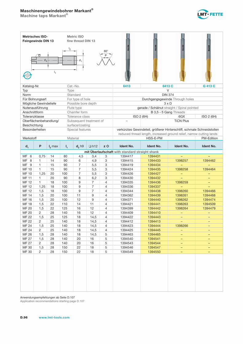
l1
d2
l2
d1
60�
P
D.96 www.lmt-tools.com
Metric ISOfine thread DIN 13
Metrisches ISO-Feingewinde DIN 13
Anwendungsempfehlungen ab Seite D.107Application recommendations starting page D.107
Maschinengewindebohrer Markant®
Machine taps Markant®
Katalog-Nr. Cat.-No. 6413 6413 C G 413 CTyp Type VNorm Standard DIN 374Für Bohrungsart For type of hole Durchgangsgewinde Through holesMögliche Gewindetiefe Possible bore depth 3 x DNutenausführung Flute type gerade / Schälnut straight / Spiral pointedAnschnittform Chamfer form B 3,5 - 5 Gang ThreadsToleranzklasse Tolerance class ISO 2 (6H) 6GX ISO 2 (6H)Oberflächenbehandlung/Beschichtung
Subsequent treatment of surface/coating
– TiCN Plus
Besonderheiten Special features verkürztes Gewindeteil, größerer Hinterschliff, schmale Schneidstollen reduced thread length, increased ground relief, narrow cutting lands
Werkstoff Material HSS-E-PM PM-Edition
d1 P l2 max l1 d2 h9 ❑ h12 z Ident No. Ident No. Ident No. Ident No.
mit Überlaufschaft with standard straight shankMF 6 0,75 14 80 4,5 3,4 3 1394417 1394431 – –MF 8 1 14 90 6 4,9 3 1394415 1394433 1398257 1394462MF 9 1 15 90 7 5,5 3 1394419 1394434 – –MF 10 1 15 90 7 5,5 3 1394424 1394435 1398258 1394464MF 10 1,25 20 100 7 5,5 3 1394426 1394427 – –MF 11 1 20 90 8 6,2 3 1394430 1394432 – –MF 12 1 18 100 9 7 4 1394335 1394436 1398259 –MF 12 1,25 18 100 9 7 4 1394336 1394337 – –MF 12 1,5 18 100 9 7 4 1394344 1394438 1398260 1394466MF 14 1,5 20 100 11 9 4 1394362 1394439 1398261 1394468MF 16 1,5 20 100 12 9 4 1394371 1394440 1398262 1394474MF 18 1,5 22 110 14 11 4 1394421 1394441 1398263 1394509MF 20 1,5 22 125 16 12 4 1394399 1394442 1398264 1394479MF 20 2 28 140 16 12 4 1394409 1394410 – –MF 22 1,5 25 125 18 14,5 4 1394422 1394443 – –MF 22 2 25 140 18 14,5 4 1394412 1394413 – –MF 24 1,5 25 140 18 14,5 4 1394423 1394444 1398266 –MF 24 2 25 140 18 14,5 4 1394425 1394445 – –MF 26 1,5 28 140 18 14,5 5 1394463 1394465 – –MF 27 1,5 28 140 20 16 5 1394540 1394541 – –MF 27 2 28 140 20 16 5 1394543 1394544 – –MF 30 1,5 28 150 22 18 5 1394546 1394547 – –MF 30 2 28 150 22 18 5 1394549 1394550 – –
gew-082-106.indd 96 14.02.2008 15:57:54
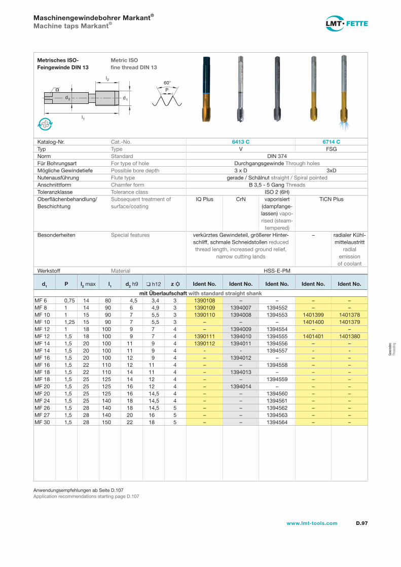
l1
d2
l2
d1
60�
P
D.97www.lmt-tools.com
Metric ISOfine thread DIN 13
Metrisches ISO-Feingewinde DIN 13
Anwendungsempfehlungen ab Seite D.107Application recommendations starting page D.107
Maschinengewindebohrer Markant® Machine taps Markant®
Katalog-Nr. Cat.-No. 6413 C 6714 CTyp Type V FSGNorm Standard DIN 374Für Bohrungsart For type of hole Durchgangsgewinde Through holesMögliche Gewindetiefe Possible bore depth 3 x D 3xDNutenausführung Flute type gerade / Schälnut straight / Spiral pointedAnschnittform Chamfer form B 3,5 - 5 Gang ThreadsToleranzklasse Tolerance class ISO 2 (6H)Oberflächenbehandlung/Beschichtung
Subsequent treatment of surface/coating
IQ Plus CrN vaporisiert (dampfange-lassen) vapo-rised (steam-
tempered)
TiCN Plus
Besonderheiten Special features verkürztes Gewindeteil, größerer Hinter-schliff, schmale Schneidstollen reduced thread length, increased ground relief,
narrow cutting lands
– radialer Kühl-mittelaustritt
radialemissionof coolant
Werkstoff Material HSS-E-PM
d1 P l2 max l1 d2 h9 ❑ h12 z Ident No. Ident No. Ident No. Ident No. Ident No.
mit Überlaufschaft with standard straight shankMF 6 0,75 14 80 4,5 3,4 3 1390108 – – – –MF 8 1 14 90 6 4,9 3 1390109 1394007 1394552 – –MF 10 1 15 90 7 5,5 3 1390110 1394008 1394553 1401399 1401378MF 10 1,25 15 90 7 5,5 3 – – – 1401400 1401379MF 12 1 18 100 9 7 4 – 1394009 1394554 – –MF 12 1,5 18 100 9 7 4 1390111 1394010 1394555 1401401 1401380MF 14 1,5 20 100 11 9 4 1390112 1394011 1394556 – –MF 14 1,5 20 100 11 9 4 - - 1394557 - -MF 16 1,5 20 100 12 9 4 – 1394012 – – –MF 16 1,5 22 110 12 11 4 – – 1394558 – –MF 18 1,5 22 110 14 11 4 – 1394013 – – –MF 18 1,5 25 125 14 12 4 – – 1394559 – –MF 20 1,5 25 125 16 12 4 – 1394014 – – –MF 20 1,5 25 125 16 14,5 4 – – 1394560 – –MF 24 1,5 25 140 18 14,5 4 – – 1394561 – –MF 26 1,5 28 140 18 14,5 5 – – 1394562 – –MF 27 1,5 28 140 20 16 5 – – 1394563 – –MF 30 1,5 28 150 22 18 5 – – 1394564 – –
Gew
inde
nTh
read
ing
gew-082-106.indd 97 14.02.2008 15:57:56
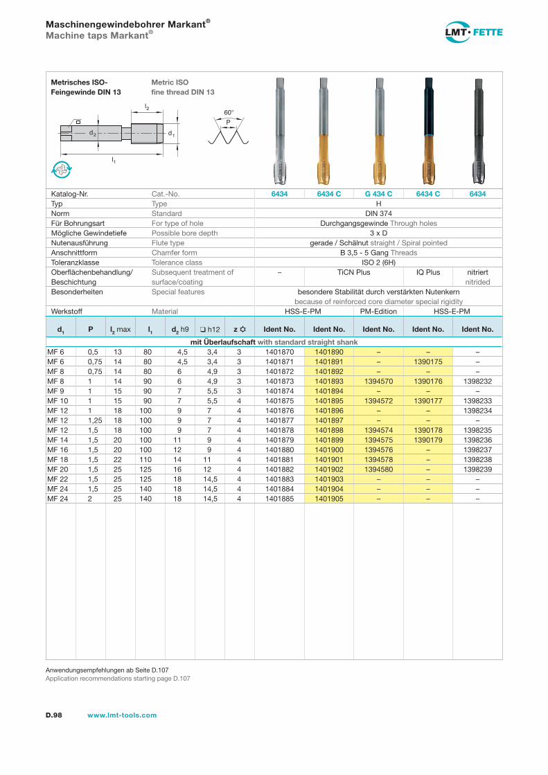
l1
d2
l2
d1
60�
P
D.98 www.lmt-tools.com
Metric ISOfine thread DIN 13
Metrisches ISO-Feingewinde DIN 13
Anwendungsempfehlungen ab Seite D.107Application recommendations starting page D.107
Maschinengewindebohrer Markant® Machine taps Markant®
Katalog-Nr. Cat.-No. 6434 6434 C G 434 C 6434 C 6434Typ Type HNorm Standard DIN 374Für Bohrungsart For type of hole Durchgangsgewinde Through holesMögliche Gewindetiefe Possible bore depth 3 x DNutenausführung Flute type gerade / Schälnut straight / Spiral pointedAnschnittform Chamfer form B 3,5 - 5 Gang ThreadsToleranzklasse Tolerance class ISO 2 (6H)Oberflächenbehandlung/Beschichtung
Subsequent treatment of surface/coating
– TiCN Plus IQ Plus nitriert nitrided
Besonderheiten Special features besondere Stabilität durch verstärkten Nutenkern because of reinforced core diameter special rigidity
Werkstoff Material HSS-E-PM PM-Edition HSS-E-PM
d1 P l2 max l1 d2 h9 ❑ h12 z Ident No. Ident No. Ident No. Ident No. Ident No.
mit Überlaufschaft with standard straight shankMF 6 0,5 13 80 4,5 3,4 3 1401870 1401890 – – –MF 6 0,75 14 80 4,5 3,4 3 1401871 1401891 – 1390175 –MF 8 0,75 14 80 6 4,9 3 1401872 1401892 – – –MF 8 1 14 90 6 4,9 3 1401873 1401893 1394570 1390176 1398232MF 9 1 15 90 7 5,5 3 1401874 1401894 – – –MF 10 1 15 90 7 5,5 4 1401875 1401895 1394572 1390177 1398233MF 12 1 18 100 9 7 4 1401876 1401896 – – 1398234MF 12 1,25 18 100 9 7 4 1401877 1401897 – – –MF 12 1,5 18 100 9 7 4 1401878 1401898 1394574 1390178 1398235MF 14 1,5 20 100 11 9 4 1401879 1401899 1394575 1390179 1398236MF 16 1,5 20 100 12 9 4 1401880 1401900 1394576 – 1398237MF 18 1,5 22 110 14 11 4 1401881 1401901 1394578 – 1398238MF 20 1,5 25 125 16 12 4 1401882 1401902 1394580 – 1398239MF 22 1,5 25 125 18 14,5 4 1401883 1401903 – – –MF 24 1,5 25 140 18 14,5 4 1401884 1401904 – – –MF 24 2 25 140 18 14,5 4 1401885 1401905 – – –
gew-082-106.indd 98 14.02.2008 15:58:02
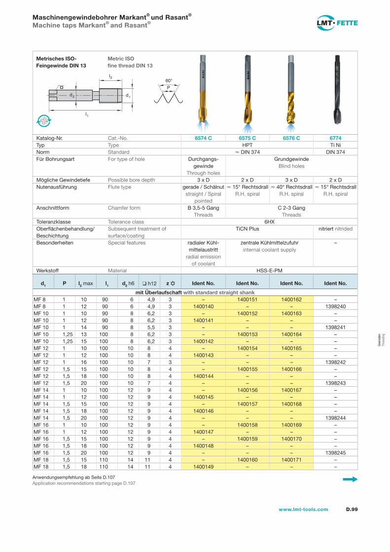
l1
d2
l2
d1
60�
P
D.99www.lmt-tools.com
Metric ISOfine thread DIN 13
Metrisches ISO-Feingewinde DIN 13
Anwendungsempfehlung ab Seite D.107Application recommendations starting page D.107
Maschinengewindebohrer Markant® und Rasant® Machine taps Markant® and Rasant®
Katalog-Nr. Cat.-No. 6574 C 6575 C 6576 C 6774Typ Type HPT Ti NiNorm Standard � DIN 374 DIN 374Für Bohrungsart For type of hole Durchgangs-
gewinde Through holes
Grundgewinde Blind holes
Mögliche Gewindetiefe Possible bore depth 3 x D 2 x D 3 x D 2 x DNutenausführung Flute type gerade / Schälnut
straight / Spiral pointed
� 15° Rechtsdrall R.H. spiral
� 40° Rechtsdrall R.H. spiral
� 15° Rechtsdrall R.H. spiral
Anschnittform Chamfer form B 3,5-5 Gang Threads
C 2-3 Gang Threads
Toleranzklasse Tolerance class 6HXOberflächenbehandlung/Beschichtung
Subsequent treatment of surface/coating
TiCN Plus nitriert nitrided
Besonderheiten Special features radialer Kühl-mittelaustritt
radial emissionof coolant
zentrale Kühlmittelzufuhrinternal coolant supply
–
Werkstoff Material HSS-E-PM
d1 P l2 max l1 d2 h6 ❑ h12 z Ident No. Ident No. Ident No. Ident No.
mit Überlaufschaft with standard straight shankMF 8 1 10 90 6 4,9 3 – 1400151 1400162 –MF 8 1 12 90 6 4,9 3 1400140 – – 1398240MF 10 1 10 90 8 6,2 3 – 1400152 1400163 –MF 10 1 12 90 8 6,2 3 1400141 – – –MF 10 1 14 90 8 5,5 3 – – – 1398241MF 10 1,25 13 100 8 6,2 3 – 1400153 1400164 –MF 10 1,25 15 100 8 6,2 3 1400142 – – –MF 12 1 10 100 10 8 4 – 1400154 1400165 –MF 12 1 12 100 10 8 4 1400143 – – –MF 12 1 16 100 10 7 3 – – – 1398242MF 12 1,5 15 100 10 8 4 – 1400155 1400166 –MF 12 1,5 18 100 10 8 4 1400144 – – –MF 12 1,5 20 100 10 7 4 – – – 1398243MF 14 1 10 100 12 9 4 – 1400156 1400167 –MF 14 1 12 100 12 9 4 1400145 – – –MF 14 1,5 15 100 12 9 4 – 1400157 1400168 –MF 14 1,5 18 100 12 9 4 1400146 – – –MF 14 1,5 20 100 12 9 4 – – – 1398244MF 16 1 10 100 12 9 4 – 1400158 1400169 –MF 16 1 12 100 12 9 4 1400147 – – –MF 16 1,5 15 100 12 9 4 – 1400159 1400170 –MF 16 1,5 18 100 12 9 4 1400148 – – –MF 16 1,5 20 100 12 9 4 – – – 1398245MF 18 1,5 15 110 14 11 4 – 1400160 1400171 –MF 18 1,5 18 110 14 11 4 1400149 – – –
Gew
inde
nTh
read
ing
gew-082-106.indd 99 14.02.2008 15:58:18
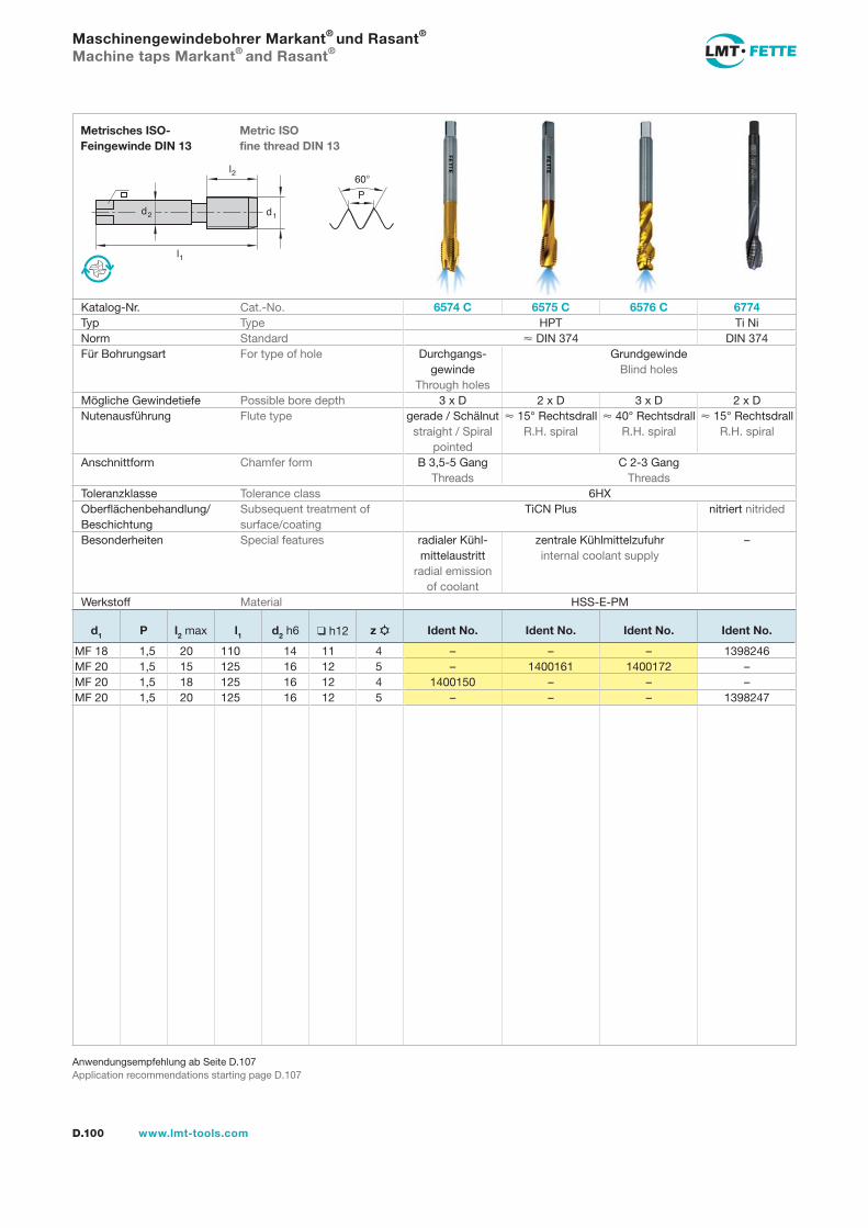
D.100 www.lmt-tools.com
Anwendungsempfehlung ab Seite D.107Application recommendations starting page D.107
Maschinengewindebohrer Markant® und Rasant® Machine taps Markant® and Rasant®
l1
d2
l2
d1
60�
P
Metric ISOfine thread DIN 13
Metrisches ISO-Feingewinde DIN 13
Katalog-Nr. Cat.-No. 6574 C 6575 C 6576 C 6774Typ Type HPT Ti NiNorm Standard � DIN 374 DIN 374Für Bohrungsart For type of hole Durchgangs-
gewinde Through holes
Grundgewinde Blind holes
Mögliche Gewindetiefe Possible bore depth 3 x D 2 x D 3 x D 2 x DNutenausführung Flute type gerade / Schälnut
straight / Spiral pointed
� 15° Rechtsdrall R.H. spiral
� 40° Rechtsdrall R.H. spiral
� 15° Rechtsdrall R.H. spiral
Anschnittform Chamfer form B 3,5-5 Gang Threads
C 2-3 Gang Threads
Toleranzklasse Tolerance class 6HXOberflächenbehandlung/Beschichtung
Subsequent treatment of surface/coating
TiCN Plus nitriert nitrided
Besonderheiten Special features radialer Kühl-mittelaustritt
radial emissionof coolant
zentrale Kühlmittelzufuhrinternal coolant supply
–
Werkstoff Material HSS-E-PM
d1 P l2 max l1 d2 h6 ❑ h12 z Ident No. Ident No. Ident No. Ident No.
MF 18 1,5 20 110 14 11 4 – – – 1398246MF 20 1,5 15 125 16 12 5 – 1400161 1400172 –MF 20 1,5 18 125 16 12 4 1400150 – – –MF 20 1,5 20 125 16 12 5 – – – 1398247
gew-082-106.indd 100 14.02.2008 15:58:27
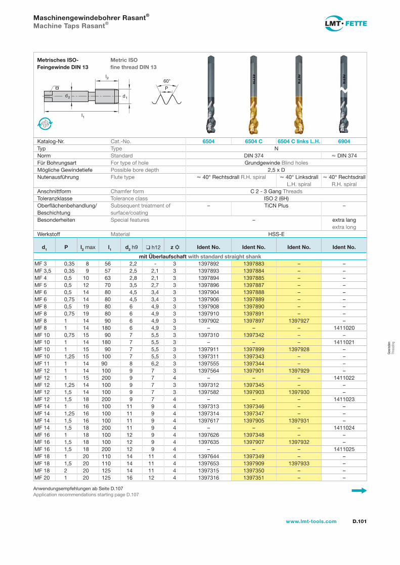
l1
d2
l2
d1
60�
P
D.101www.lmt-tools.com
Metric ISOfine thread DIN 13
Metrisches ISO-Feingewinde DIN 13
Anwendungsempfehlungen ab Seite D.107Application recommendations starting page D.107
Maschinengewindebohrer Rasant®
Machine Taps Rasant®
Katalog-Nr. Cat.-No. 6504 6504 C 6504 C links L.H. 6904Typ Type NNorm Standard DIN 374 � DIN 374Für Bohrungsart For type of hole Grundgewinde Blind holesMögliche Gewindetiefe Possible bore depth 2,5 x DNutenausführung Flute type � 40° Rechtsdrall R.H. spiral � 40° Linksdrall
L.H. spiral� 40° Rechtsdrall
R.H. spiralAnschnittform Chamfer form C 2 - 3 Gang ThreadsToleranzklasse Tolerance class ISO 2 (6H)Oberflächenbehandlung/Beschichtung
Subsequent treatment of surface/coating
– TiCN Plus –
Besonderheiten Special features – extra lang extra long
Werkstoff Material HSS-E
d1 P l2 max l1 d2 h9 ❑ h12 z Ident No. Ident No. Ident No. Ident No.
mit Überlaufschaft with standard straight shankMF 3 0,35 8 56 2,2 - 3 1397892 1397883 – –MF 3,5 0,35 9 57 2,5 2,1 3 1397893 1397884 – –MF 4 0,5 10 63 2,8 2,1 3 1397894 1397885 – –MF 5 0,5 12 70 3,5 2,7 3 1397896 1397887 – –MF 6 0,5 14 80 4,5 3,4 3 1397904 1397888 – –MF 6 0,75 14 80 4,5 3,4 3 1397906 1397889 – –MF 8 0,5 19 80 6 4,9 3 1397908 1397890 – –MF 8 0,75 19 80 6 4,9 3 1397910 1397891 – –MF 8 1 14 90 6 4,9 3 1397902 1397897 1397927 –MF 8 1 14 180 6 4,9 3 – – – 1411020MF 10 0,75 15 90 7 5,5 3 1397310 1397342 – –MF 10 1 14 180 7 5,5 3 – – – 1411021MF 10 1 15 90 7 5,5 3 1397911 1397899 1397928 –MF 10 1,25 15 100 7 5,5 3 1397311 1397343 – –MF 11 1 14 90 8 6,2 3 1397555 1397344 – –MF 12 1 14 100 9 7 3 1397564 1397901 1397929 –MF 12 1 15 200 9 7 4 – – – 1411022MF 12 1,25 14 100 9 7 3 1397312 1397345 – –MF 12 1,5 14 100 9 7 3 1397582 1397903 1397930 –MF 12 1,5 18 200 9 7 4 – – – 1411023MF 14 1 16 100 11 9 4 1397313 1397346 – –MF 14 1,25 16 100 11 9 4 1397314 1397347 – –MF 14 1,5 16 100 11 9 4 1397617 1397905 1397931 –MF 14 1,5 18 200 11 9 4 – – – 1411024MF 16 1 18 100 12 9 4 1397626 1397348 – –MF 16 1,5 18 100 12 9 4 1397635 1397907 1397932 –MF 16 1,5 18 200 12 9 4 – – – 1411025MF 18 1 20 110 14 11 4 1397644 1397349 – –MF 18 1,5 20 110 14 11 4 1397653 1397909 1397933 –MF 18 2 20 125 14 11 4 1397315 1397350 – –MF 20 1 20 125 16 12 4 1397316 1397351 – –
Gew
inde
nTh
read
ing
gew-082-106.indd 101 14.02.2008 15:58:34
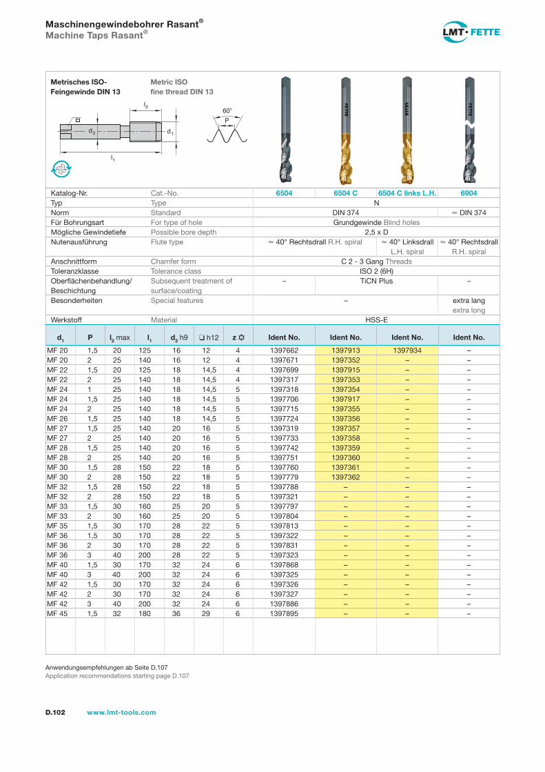
D.102 www.lmt-tools.com
l1
d2
l2
d1
60
P
Metric ISO fine thread DIN 13
Metrisches ISO- Feingewinde DIN 13
Anwendungsempfehlungen ab Seite D.107Application recommendations starting page D.107
Maschinengewindebohrer Rasant®
Machine Taps Rasant®
Katalog-Nr. Cat.-No. 6504 6504 C 6504 C links L.H. 6904Typ Type NNorm Standard DIN 374 DIN 374Für Bohrungsart For type of hole Grundgewinde Blind holesMögliche Gewindetiefe Possible bore depth 2,5 x DNutenausführung Flute type 40° Rechtsdrall R.H. spiral 40° Linksdrall
L.H. spiral 40° Rechtsdrall
R.H. spiralAnschnittform Chamfer form C 2 - 3 Gang ThreadsToleranzklasse Tolerance class ISO 2 (6H)Oberflächenbehandlung/Beschichtung
Subsequent treatment of surface/coating
– TiCN Plus –
Besonderheiten Special features – extra lang extra long
Werkstoff Material HSS-E
d1 P l2 max l1 d2 h9 h12 z Ident No. Ident No. Ident No. Ident No.
MF 20 1,5 20 125 16 12 4 1397662 1397913 1397934 –MF 20 2 25 140 16 12 4 1397671 1397352 – –MF 22 1,5 20 125 18 14,5 4 1397699 1397915 – –MF 22 2 25 140 18 14,5 4 1397317 1397353 – –MF 24 1 25 140 18 14,5 5 1397318 1397354 – –MF 24 1,5 25 140 18 14,5 5 1397706 1397917 – –MF 24 2 25 140 18 14,5 5 1397715 1397355 – –MF 26 1,5 25 140 18 14,5 5 1397724 1397356 – –MF 27 1,5 25 140 20 16 5 1397319 1397357 – –MF 27 2 25 140 20 16 5 1397733 1397358 – –MF 28 1,5 25 140 20 16 5 1397742 1397359 – –MF 28 2 25 140 20 16 5 1397751 1397360 – –MF 30 1,5 28 150 22 18 5 1397760 1397361 – –MF 30 2 28 150 22 18 5 1397779 1397362 – –MF 32 1,5 28 150 22 18 5 1397788 – – –MF 32 2 28 150 22 18 5 1397321 – – –MF 33 1,5 30 160 25 20 5 1397797 – – –MF 33 2 30 160 25 20 5 1397804 – – –MF 35 1,5 30 170 28 22 5 1397813 – – –MF 36 1,5 30 170 28 22 5 1397322 – – –MF 36 2 30 170 28 22 5 1397831 – – –MF 36 3 40 200 28 22 5 1397323 – – –MF 40 1,5 30 170 32 24 6 1397868 – – –MF 40 3 40 200 32 24 6 1397325 – – –MF 42 1,5 30 170 32 24 6 1397326 – – –MF 42 2 30 170 32 24 6 1397327 – – –MF 42 3 40 200 32 24 6 1397886 – – –MF 45 1,5 32 180 36 29 6 1397895 – – –
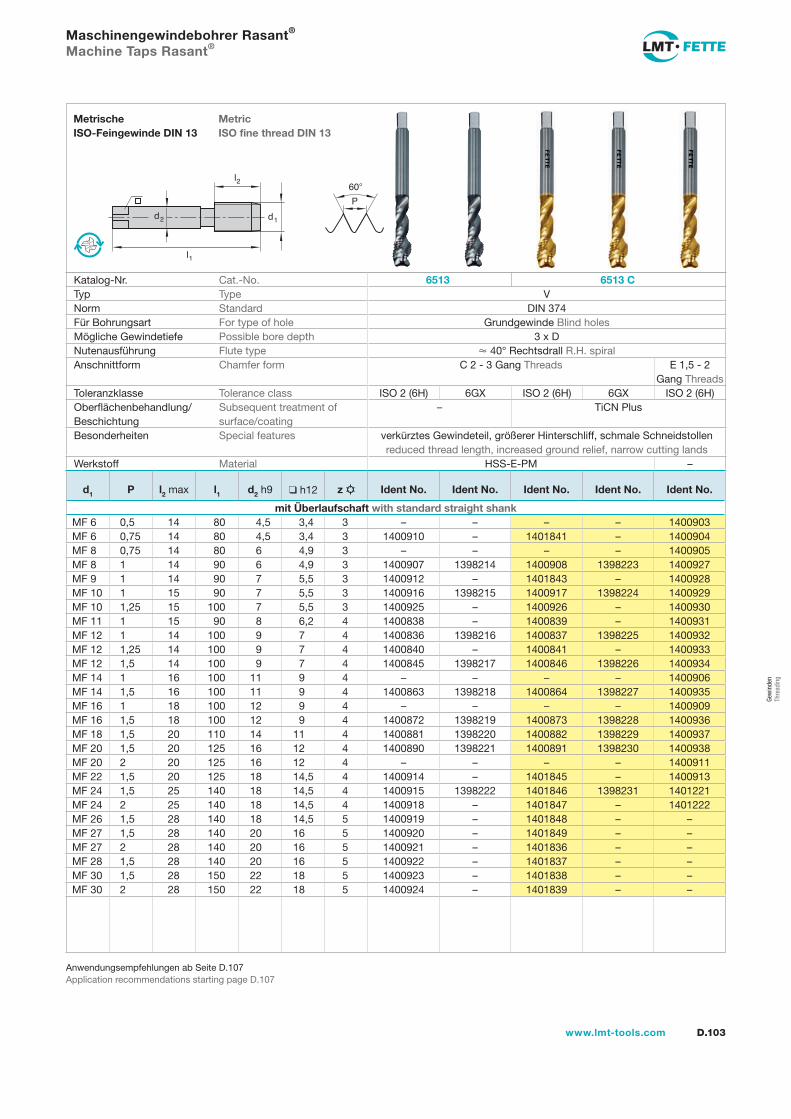
l1
d2
l2
d1
60�
P
D.103www.lmt-tools.com
MetricISO fine thread DIN 13
MetrischeISO-Feingewinde DIN 13
Anwendungsempfehlungen ab Seite D.107Application recommendations starting page D.107
Maschinengewindebohrer Rasant® Machine Taps Rasant®
Katalog-Nr. Cat.-No. 6513 6513 CTyp Type VNorm Standard DIN 374Für Bohrungsart For type of hole Grundgewinde Blind holesMögliche Gewindetiefe Possible bore depth 3 x DNutenausführung Flute type � 40° Rechtsdrall R.H. spiralAnschnittform Chamfer form C 2 - 3 Gang Threads E 1,5 - 2
Gang ThreadsToleranzklasse Tolerance class ISO 2 (6H) 6GX ISO 2 (6H) 6GX ISO 2 (6H)Oberflächenbehandlung/Beschichtung
Subsequent treatment ofsurface/coating
– TiCN Plus
Besonderheiten Special features verkürztes Gewindeteil, größerer Hinterschliff, schmale Schneidstollen reduced thread length, increased ground relief, narrow cutting lands
Werkstoff Material HSS-E-PM –
d1 P l2 max l1 d2 h9 ❑ h12 z Ident No. Ident No. Ident No. Ident No. Ident No.
mit Überlaufschaft with standard straight shankMF 6 0,5 14 80 4,5 3,4 3 – – – – 1400903MF 6 0,75 14 80 4,5 3,4 3 1400910 – 1401841 – 1400904MF 8 0,75 14 80 6 4,9 3 – – – – 1400905MF 8 1 14 90 6 4,9 3 1400907 1398214 1400908 1398223 1400927MF 9 1 14 90 7 5,5 3 1400912 – 1401843 – 1400928MF 10 1 15 90 7 5,5 3 1400916 1398215 1400917 1398224 1400929MF 10 1,25 15 100 7 5,5 3 1400925 – 1400926 – 1400930MF 11 1 15 90 8 6,2 4 1400838 – 1400839 – 1400931MF 12 1 14 100 9 7 4 1400836 1398216 1400837 1398225 1400932MF 12 1,25 14 100 9 7 4 1400840 – 1400841 – 1400933MF 12 1,5 14 100 9 7 4 1400845 1398217 1400846 1398226 1400934MF 14 1 16 100 11 9 4 – – – – 1400906MF 14 1,5 16 100 11 9 4 1400863 1398218 1400864 1398227 1400935MF 16 1 18 100 12 9 4 – – – – 1400909MF 16 1,5 18 100 12 9 4 1400872 1398219 1400873 1398228 1400936MF 18 1,5 20 110 14 11 4 1400881 1398220 1400882 1398229 1400937MF 20 1,5 20 125 16 12 4 1400890 1398221 1400891 1398230 1400938MF 20 2 20 125 16 12 4 – – – – 1400911MF 22 1,5 20 125 18 14,5 4 1400914 – 1401845 – 1400913MF 24 1,5 25 140 18 14,5 4 1400915 1398222 1401846 1398231 1401221MF 24 2 25 140 18 14,5 4 1400918 – 1401847 – 1401222MF 26 1,5 28 140 18 14,5 5 1400919 – 1401848 – –MF 27 1,5 28 140 20 16 5 1400920 – 1401849 – –MF 27 2 28 140 20 16 5 1400921 – 1401836 – –MF 28 1,5 28 140 20 16 5 1400922 – 1401837 – –MF 30 1,5 28 150 22 18 5 1400923 – 1401838 – –MF 30 2 28 150 22 18 5 1400924 – 1401839 – –
Gew
inde
nTh
read
ing
gew-082-106.indd 103 14.02.2008 15:58:39
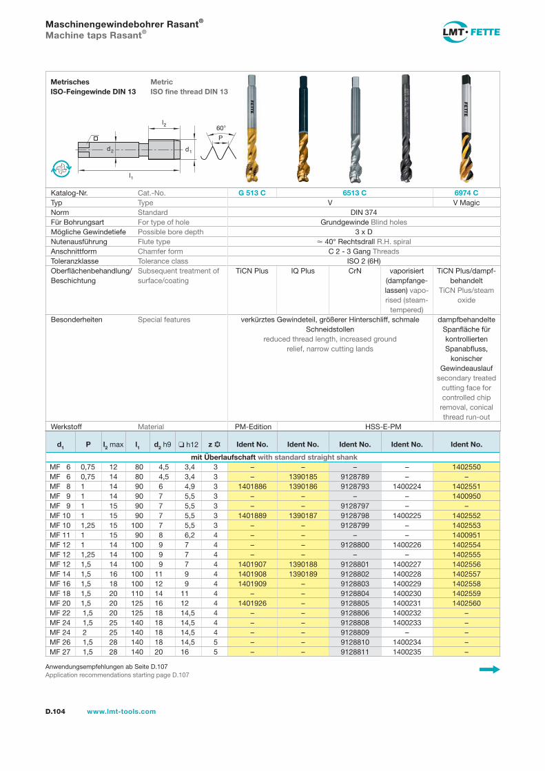
l1
d2
l2
d1
60�
P
D.104 www.lmt-tools.com
MetricISO fine thread DIN 13
MetrischesISO-Feingewinde DIN 13
Anwendungsempfehlungen ab Seite D.107Application recommendations starting page D.107
Maschinengewindebohrer Rasant® Machine taps Rasant®
Katalog-Nr. Cat.-No. G 513 C 6513 C 6974 CTyp Type V V MagicNorm Standard DIN 374Für Bohrungsart For type of hole Grundgewinde Blind holesMögliche Gewindetiefe Possible bore depth 3 x DNutenausführung Flute type � 40° Rechtsdrall R.H. spiralAnschnittform Chamfer form C 2 - 3 Gang ThreadsToleranzklasse Tolerance class ISO 2 (6H)Oberflächenbehandlung/Beschichtung
Subsequent treatment ofsurface/coating
TiCN Plus IQ Plus CrN vaporisiert (dampfange-lassen) vapo-rised (steam-
tempered)
TiCN Plus/dampf-behandelt
TiCN Plus/steam oxide
Besonderheiten Special features verkürztes Gewindeteil, größerer Hinterschliff, schmale Schneidstollen
reduced thread length, increased groundrelief, narrow cutting lands
dampfbehandelte Spanfläche fürkontrollierten Spanabfluss,
konischerGewindeauslauf
secondary treated cutting face for controlled chip
removal, conical thread run-out
Werkstoff Material PM-Edition HSS-E-PM
d1 P l2 max l1 d2 h9 ❑ h12 z Ident No. Ident No. Ident No. Ident No. Ident No.
mit Überlaufschaft with standard straight shankMF 6 0,75 12 80 4,5 3,4 3 – – – – 1402550MF 6 0,75 14 80 4,5 3,4 3 – 1390185 9128789 – –MF 8 1 14 90 6 4,9 3 1401886 1390186 9128793 1400224 1402551MF 9 1 14 90 7 5,5 3 – – – – 1400950MF 9 1 15 90 7 5,5 3 – – 9128797 – –MF 10 1 15 90 7 5,5 3 1401889 1390187 9128798 1400225 1402552MF 10 1,25 15 100 7 5,5 3 – – 9128799 – 1402553MF 11 1 15 90 8 6,2 4 – – – – 1400951MF 12 1 14 100 9 7 4 – – 9128800 1400226 1402554MF 12 1,25 14 100 9 7 4 – – – – 1402555MF 12 1,5 14 100 9 7 4 1401907 1390188 9128801 1400227 1402556MF 14 1,5 16 100 11 9 4 1401908 1390189 9128802 1400228 1402557MF 16 1,5 18 100 12 9 4 1401909 – 9128803 1400229 1402558MF 18 1,5 20 110 14 11 4 – – 9128804 1400230 1402559MF 20 1,5 20 125 16 12 4 1401926 – 9128805 1400231 1402560MF 22 1,5 20 125 18 14,5 4 – – 9128806 1400232 –MF 24 1,5 25 140 18 14,5 4 – – 9128808 1400233 –MF 24 2 25 140 18 14,5 4 – – 9128809 – –MF 26 1,5 28 140 18 14,5 5 – – 9128810 1400234 –MF 27 1,5 28 140 20 16 5 – – 9128811 1400235 –
gew-082-106.indd 104 14.02.2008 15:58:43
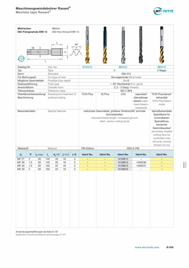
D.105www.lmt-tools.com
Anwendungsempfehlungen ab Seite D.107Application recommendations starting page D.107
Maschinengewindebohrer Rasant® Machine taps Rasant®
l1
d2
l2
d1
60�
P
MetricISO fine thread DIN 13
MetrischesISO-Feingewinde DIN 13
Katalog-Nr. Cat.-No. G 513 C 6513 C 6974 CTyp Type V V MagicNorm Standard DIN 374Für Bohrungsart For type of hole Grundgewinde Blind holesMögliche Gewindetiefe Possible bore depth 3 x DNutenausführung Flute type � 40° Rechtsdrall R.H. spiralAnschnittform Chamfer form C 2 - 3 Gang ThreadsToleranzklasse Tolerance class ISO 2 (6H)Oberflächenbehandlung/Beschichtung
Subsequent treatment ofsurface/coating
TiCN Plus IQ Plus CrN vaporisiert (dampfange-lassen) vapo-rised (steam-
tempered)
TiCN Plus/dampf-behandelt
TiCN Plus/steam oxide
Besonderheiten Special features verkürztes Gewindeteil, größerer Hinterschliff, schmale Schneidstollen
reduced thread length, increased groundrelief, narrow cutting lands
dampfbehandelte Spanfläche fürkontrollierten Spanabfluss,
konischerGewindeauslauf
secondary treated cutting face for controlled chip
removal, conical thread run-out
Werkstoff Material PM-Edition HSS-E-PM
d1 P l2 max l1 d2 h9 ❑ h12 z Ident No. Ident No. Ident No. Ident No. Ident No.
MF 27 2 28 140 20 16 5 – – 9128812 – –MF 28 1,5 28 140 20 16 5 – – 9128813 1400236 –MF 30 1,5 28 150 22 18 5 – – 9128815 1400237 –MF 30 2 28 150 22 18 5 – – 9128816 – –
Gew
inde
nTh
read
ing
gew-082-106.indd 105 14.02.2008 15:58:50
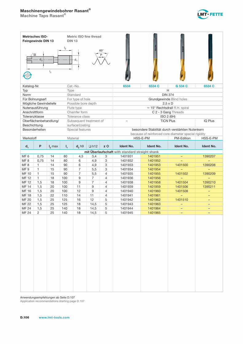
l1
d2
l2
d1
60�
P
D.106 www.lmt-tools.com
Metric ISO fine thread DIN 13
Metrisches ISO-Feingewinde DIN 13
Anwendungsempfehlungen ab Seite D.107Application recommendations starting page D.107
Maschinengewindebohrer Rasant® Machine Taps Rasant®
Katalog-Nr. Cat.-No. 6534 6534 C G 534 C 6534 CTyp Type HNorm Standard DIN 374Für Bohrungsart For type of hole Grundgewinde Blind holesMögliche Gewindetiefe Possible bore depth 2,5 x DNutenausführung Flute type � 15° Rechtsdrall R.H. spiralAnschnittform Chamfer form C 2 - 3 Gang ThreadsToleranzklasse Tolerance class ISO 2 (6H)Oberflächenbehandlung/Beschichtung
Subsequent treatment of surface/coating
– TiCN Plus IQ Plus
Besonderheiten Special features besondere Stabilität durch verstärkten Nutenkernbecause of reinforced core diameter special rigidity
Werkstoff Material HSS-E-PM PM-Edition HSS-E-PM
d1 P l2 max l1 d2 h9 ❑ h12 z Ident No. Ident No. Ident No. Ident No.
mit Überlaufschaft with standard straight shankMF 6 0,75 14 80 4,5 3,4 3 1401931 1401951 – 1390207MF 8 0,75 14 80 6 4,9 3 1401932 1401952 – –MF 8 1 14 90 6 4,9 3 1401933 1401953 1401500 1390208MF 9 1 15 90 7 5,5 3 1401934 1401954 – –MF 10 1 15 90 7 5,5 4 1401935 1401955 1401502 1390209MF 12 1 18 100 9 7 4 1401936 1401956 – –MF 12 1,5 18 100 9 7 4 1401938 1401958 1401504 1390210MF 14 1,5 20 100 11 9 4 1401939 1401959 1401506 1390211MF 16 1,5 20 100 12 9 4 1401940 1401960 1401508 –MF 18 1,5 22 110 14 11 4 1401941 1401961 – –MF 20 1,5 25 125 16 12 5 1401942 1401962 1401510 –MF 22 1,5 25 125 18 14,5 5 1401943 1401963 – –MF 24 1,5 25 140 18 14,5 5 1401944 1401964 – –MF 24 2 25 140 18 14,5 5 1401945 1401965 – –
gew-082-106.indd 106 14.02.2008 15:58:56
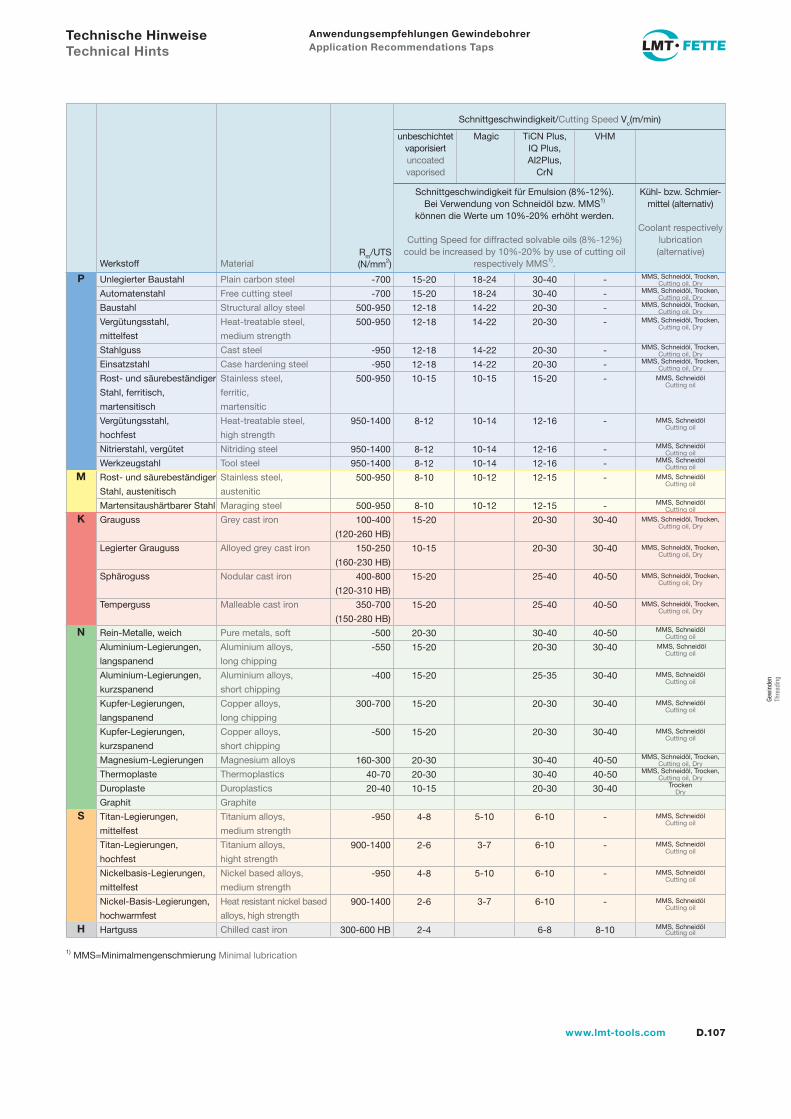
D.107www.lmt-tools.com
18-24
18-24
14-22
14-22
14-22
14-22
10-15
10-14
10-14
10-14
10-12
10-12
5-10
3-7
5-10
3-7
30-40
30-40
20-30
20-30
20-30
20-30
15-20
12-16
12-16
12-16
12-15
12-15
20-30
20-30
25-40
25-40
30-40
20-30
25-35
20-30
20-30
30-40
30-40
20-30
6-10
6-10
6-10
6-10
6-8
-
-
-
-
-
-
-
-
-
-
-
-
30-40
30-40
40-50
40-50
40-50
30-40
30-40
30-40
30-40
40-50
40-50
30-40
-
-
-
-
8-10
15-20
15-20
12-18
12-18
12-18
12-18
10-15
8-12
8-12
8-12
8-10
8-10
15-20
10-15
15-20
15-20
20-30
15-20
15-20
15-20
15-20
20-30
20-30
10-15
4-8
2-6
4-8
2-6
2-4
MMS, Schneidöl, Trocken, Cutting oil, Dry
MMS, Schneidöl, Trocken, Cutting oil, Dry
MMS, Schneidöl, Trocken, Cutting oil, Dry
MMS, Schneidöl, Trocken, Cutting oil, Dry
MMS, Schneidöl, Trocken, Cutting oil, Dry
MMS, Schneidöl, Trocken, Cutting oil, Dry
MMS, Schneidöl Cutting oil
MMS, Schneidöl Cutting oil
MMS, Schneidöl Cutting oil
MMS, Schneidöl Cutting oil
MMS, Schneidöl Cutting oil
MMS, Schneidöl Cutting oil
MMS, Schneidöl, Trocken, Cutting oil, Dry
MMS, Schneidöl, Trocken, Cutting oil, Dry
MMS, Schneidöl, Trocken, Cutting oil, Dry
MMS, Schneidöl, Trocken, Cutting oil, Dry
MMS, Schneidöl Cutting oil
MMS, Schneidöl Cutting oil
MMS, Schneidöl Cutting oil
MMS, Schneidöl Cutting oil
MMS, Schneidöl Cutting oil
MMS, Schneidöl, Trocken, Cutting oil, Dry
MMS, Schneidöl, Trocken, Cutting oil, Dry
Trocken Dry
MMS, Schneidöl Cutting oil
MMS, Schneidöl Cutting oil
MMS, Schneidöl Cutting oil
MMS, Schneidöl Cutting oil
MMS, Schneidöl Cutting oil
Anwendungsempfehlungen Gewindebohrer Application Recommendations Taps
1) MMS=Minimalmengenschmierung Minimal lubrication
Rm/UTS(N/mm2)
Schnittgeschwindigkeit/Cutting Speed Vc(m/min)
unbeschichtetvaporisiertuncoatedvaporised
Magic
Schnittgeschwindigkeit für Emulsion (8%-12%). Bei Verwendung von Schneidöl bzw. MMS1)
können die Werte um 10%-20% erhöht werden.
Cutting Speed for diffracted solvable oils (8%-12%) could be increased by 10%-20% by use of cutting oil
respectively MMS1).
Kühl- bzw. Schmier-mittel (alternativ)
Coolant respectively lubrication (alternative)
TiCN Plus,IQ Plus,AI2Plus,
CrN
VHM
Unlegierter Baustahl Plain carbon steel
Automatenstahl Free cutting steel
Baustahl Structural alloy steel
Vergütungsstahl, Heat-treatable steel,
mittelfest medium strength
Stahlguss Cast steel
Einsatzstahl Case hardening steel
Rost- und säurebeständiger Stainless steel,
Stahl, ferritisch, ferritic,
martensitisch martensitic
Vergütungsstahl, Heat-treatable steel,
hochfest high strength
Nitrierstahl, vergütet Nitriding steel
Werkzeugstahl Tool steel
Rost- und säurebeständiger Stainless steel,
Stahl, austenitisch austenitic
Martensitaushärtbarer Stahl Maraging steel
Grauguss Grey cast iron
Legierter Grauguss Alloyed grey cast iron
Sphäroguss Nodular cast iron
Temperguss Malleable cast iron
Rein-Metalle, weich Pure metals, soft
Aluminium-Legierungen, Aluminium alloys,
langspanend long chipping
Aluminium-Legierungen, Aluminium alloys,
kurzspanend short chipping
Kupfer-Legierungen, Copper alloys,
langspanend long chipping
Kupfer-Legierungen, Copper alloys,
kurzspanend short chipping
Magnesium-Legierungen Magnesium alloys
Thermoplaste Thermoplastics
Duroplaste Duroplastics
Graphit Graphite
Titan-Legierungen, Titanium alloys,
mittelfest medium strength
Titan-Legierungen, Titanium alloys,
hochfest hight strength
Nickelbasis-Legierungen, Nickel based alloys,
mittelfest medium strength
Nickel-Basis-Legierungen, Heat resistant nickel based
hochwarmfest alloys, high strength
Hartguss Chilled cast iron
Werkstoff Material
-700
-700
500-950
500-950
-950
-950
500-950
950-1400
950-1400
950-1400
500-950
500-950
100-400
(120-260 HB)
150-250
(160-230 HB)
400-800
(120-310 HB)
350-700
(150-280 HB)
-500
-550
-400
300-700
-500
160-300
40-70
20-40
-950
900-1400
-950
900-1400
300-600 HB
Technische Hinweise Technical Hints
P
M
K
N
S
H
Gew
inde
n Th
read
ing

D.108 www.lmt-tools.com
Gewindebohrer UNC/UNFTaps UNC/UNF

D.109www.lmt-tools.com
Gewindebohrer UNC/UNF Taps UNC/UNF
Gew
inde
n Th
read
ing
D.110 Auswahlübersicht Gewindebohrer Selection table taps
D.113 Typenbeschreibungen Type descriptions
Typen Type
N D.116, D.127V D.120, D.125, D.130Vdry-S D.126, D.132V-Magic D.123, D.133
D.136 Anwendungsempfehlungen Application recommendations
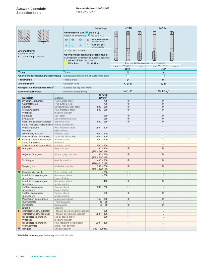
D.110 www.lmt-tools.com
Typen Types
Oberflächenbehandlung/Beschichtung Subsequent treatment of surface/coating
≈ Drallwinkel ≈ Helix angle
Anschnittform Chamfer form
Geeignet für Trocken und MMS1) Suitable for dry and MMS
Durchmesserbereich Diameter range (mm)
Anschnittform:Chamfer form:C 2 - 3 Gang Threads
Seite Page D.116 D.127
Rm/UTSWerkstoff Material (N/mm2)Unlegierter Baustahl Plain carbon steel – 700Automatenstahl Free cutting steel – 700Baustahl Structural low alloy steel 500 – 950Vergütungsstahl, Heat-treatable steel, 500 – 950mittelfest medium strengthStahlguss Cast steel – 950Einsatzstahl Case hardening steel – 950Rost- und säurebeständiger Stainless steel, 500 – 950Stahl, ferritisch, martensitisch ferritic, martensiticVergütungsstahl, Heat-treatable steel, 950 – 1400hochfest high strengthNitrierstahl, vergütet Nitriding steel 950 – 1400Werkzeugstahl (bis 45 HRC) Tool steel (to 45 HRC) 950 – 1400Rost- und säurebeständiger Stainless steel, 500 – 950Stahl, austenitisch austeniticMartensitaushärtbarer Stahl Maraging steel 500 – 950Grauguss Grey cast iron 100 – 400 (120 – 260 HB)Legierter Grauguss Alloyed grey cast iron 150 – 250 (160 – 230 HB)Sphäroguss Nodular cast iron 400 – 800 (120 – 310 HB)Temperguss Malleable cast iron 350 – 700 (150 – 280 HB)Rein-Metalle, weich Pure metals, soft – 500Aluminium-Legierungen, Aluminium alloys, – 550langspanend long chippingAluminium-Legierungen, Aluminium alloys, – 400kurzspanend short chippingKupfer-Legierungen, Copper alloys, 300 – 700langspanend long chippingKupfer-Legierungen, Copper alloys, – 500kurzspanend short chippingMagnesium-Legierungen Magnesium alloys 150 – 300Thermoplaste Thermoplastics 40 – 70Duroplaste Duroplastics 20 – 40Graphit GraphiteTitanlegierungen, mittelfest Titanium alloys, medium strength – 950Titanlegierungen, hochfest Titanium alloys, high strength 900 – 1400Nickelbasislegierungen, Nickel based alloys, – 950mittelfest medium strengthNickelbasislegierungen, Heat resistant nickel based 900 – 1400hochwarmfest alloys, high strengthHartguss Chilled cast iron 300 – 600 HB
Gewindetiefe (z.B. bis 3 x D)Depth of thread (e.g. up to 3 x D)
~ 1-1,5 x D~ 2 x D~ 3 x D
sehr gut geeignetwell suitable
auch geeignetalso suitable
Auswahlübersicht Selection table
1) MMS=Minimalmengenschmierung Minimal lubrication
N
S
H
P
K
M
UNC UNF
3tlg. sets of 3 Nr. 1 Nr. 2 Nr. 3
2tlg. sets of 2 Nr. 1 Nr. 2
Grund- und Durchgangsgewinde blind and through hole
0° 0°
A D C A C
N N
Nr. 1–2" Nr. 1–11/2"
Oberflächenbehandlung/Beschichtung:Subsequent treatment of surface/coating: unbeschichtet uncoated
TiCN Plus IQ Plus
Gewindebohrer UNC/UNF Taps UNC/UNF
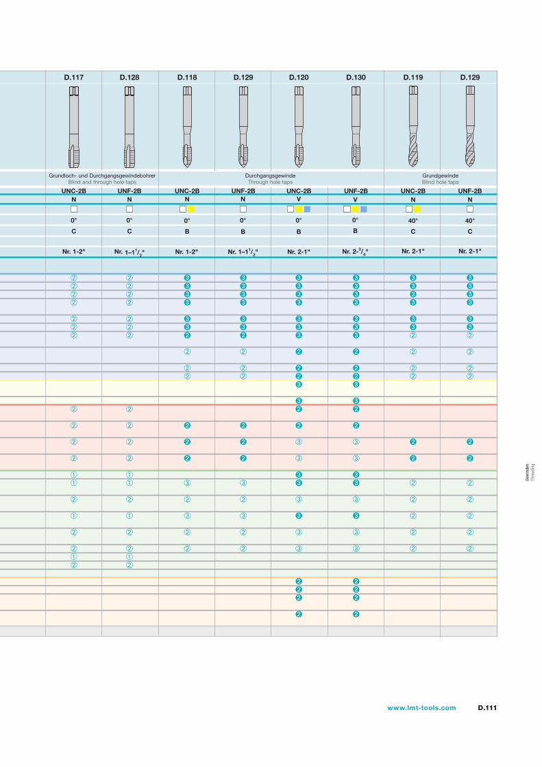
D.111www.lmt-tools.com
Grundloch- und DurchgangsgewindebohrerBlind and through hole taps
D.117 D.128
UNF-2BV
0°
B
Nr. 2-3/4"
UNC-2BN
0°
B
Nr. 1-2"
UNF-2BN
0°
B
Nr. 1–11/2"
UNC-2BV
0°
B
Nr. 2-1"
D.118 D.129 D.120 D.130
UNC-2BN
40°
C
Nr. 2-1"
UNF-2BN
40°
C
Nr. 2-1"
D.119 D.129
UNC-2B
0°
C
N
Nr. 1-2"
UNF-2BN
0°
C
Nr. 1–11/2"
DurchgangsgewindeThrough hole taps
GrundgewindeBlind hole taps
Gew
inde
n Th
read
ing
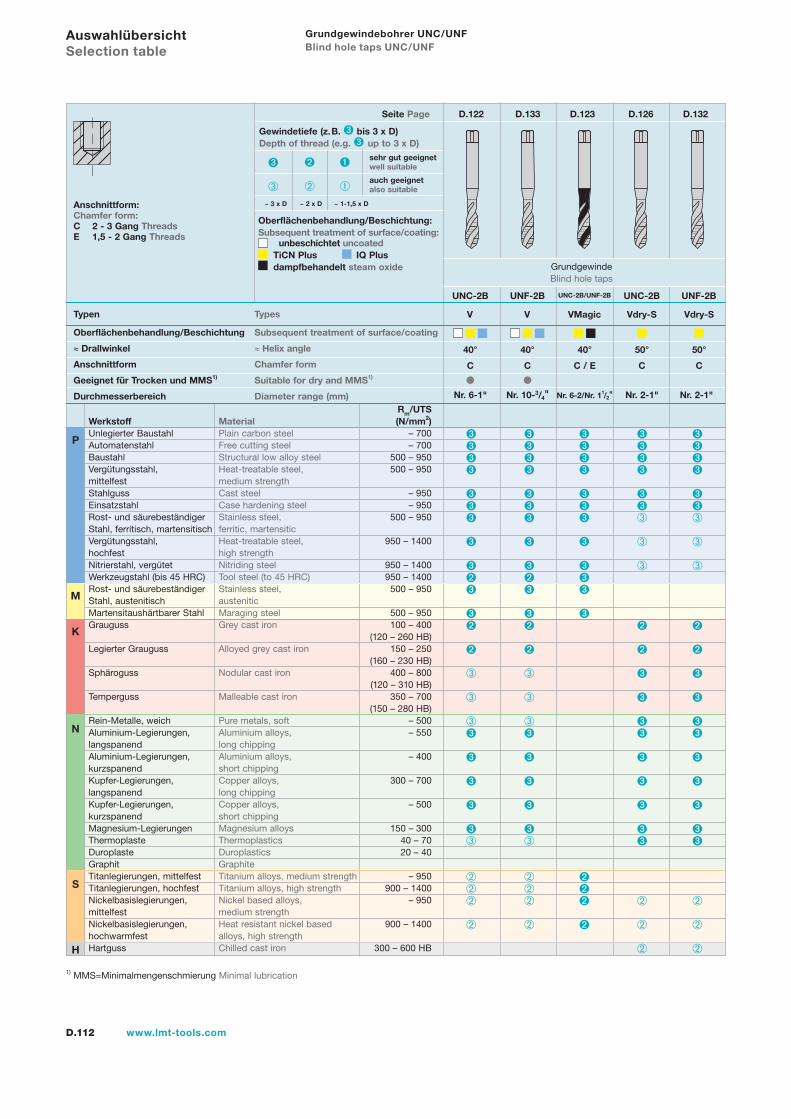
D.112 www.lmt-tools.com
Grundgewindebohrer UNC/UNF Blind hole taps UNC/UNF
Typen Types
Oberflächenbehandlung/Beschichtung Subsequent treatment of surface/coating
≈ Drallwinkel ≈ Helix angle
Anschnittform Chamfer form
Geeignet für Trocken und MMS1) Suitable for dry and MMS1)
Durchmesserbereich Diameter range (mm)
Anschnittform:Chamfer form:C 2 - 3 Gang ThreadsE 1,5 - 2 Gang Threads
Oberflächenbehandlung/Beschichtung:Subsequent treatment of surface/coating: unbeschichtet uncoated TiCN Plus IQ Plus dampfbehandelt steam oxide
Seite Page D.122 D.133 D.123 D.126 D.132
1) MMS=Minimalmengenschmierung Minimal lubrication
Rm/UTSWerkstoff Material (N/mm2)Unlegierter Baustahl Plain carbon steel – 700Automatenstahl Free cutting steel – 700Baustahl Structural low alloy steel 500 – 950Vergütungsstahl, Heat-treatable steel, 500 – 950mittelfest medium strengthStahlguss Cast steel – 950Einsatzstahl Case hardening steel – 950Rost- und säurebeständiger Stainless steel, 500 – 950Stahl, ferritisch, martensitisch ferritic, martensiticVergütungsstahl, Heat-treatable steel, 950 – 1400hochfest high strengthNitrierstahl, vergütet Nitriding steel 950 – 1400Werkzeugstahl (bis 45 HRC) Tool steel (to 45 HRC) 950 – 1400Rost- und säurebeständiger Stainless steel, 500 – 950Stahl, austenitisch austeniticMartensitaushärtbarer Stahl Maraging steel 500 – 950Grauguss Grey cast iron 100 – 400 (120 – 260 HB)Legierter Grauguss Alloyed grey cast iron 150 – 250 (160 – 230 HB)Sphäroguss Nodular cast iron 400 – 800 (120 – 310 HB)Temperguss Malleable cast iron 350 – 700 (150 – 280 HB)Rein-Metalle, weich Pure metals, soft – 500Aluminium-Legierungen, Aluminium alloys, – 550langspanend long chippingAluminium-Legierungen, Aluminium alloys, – 400kurzspanend short chippingKupfer-Legierungen, Copper alloys, 300 – 700langspanend long chippingKupfer-Legierungen, Copper alloys, – 500kurzspanend short chippingMagnesium-Legierungen Magnesium alloys 150 – 300Thermoplaste Thermoplastics 40 – 70Duroplaste Duroplastics 20 – 40Graphit GraphiteTitanlegierungen, mittelfest Titanium alloys, medium strength – 950Titanlegierungen, hochfest Titanium alloys, high strength 900 – 1400Nickelbasislegierungen, Nickel based alloys, – 950mittelfest medium strengthNickelbasislegierungen, Heat resistant nickel based 900 – 1400hochwarmfest alloys, high strengthHartguss Chilled cast iron 300 – 600 HB
40° 40° 40° 50° 50°
V V VMagic Vdry-S Vdry-S
Nr. 6-1" Nr. 10-3/4" Nr. 6-2/Nr. 11/2" Nr. 2-1" Nr. 2-1"
UNC-2B UNF-2B UNC-2B/UNF-2B UNC-2B UNF-2B
C C C / E C C
Gewindetiefe (z.B. bis 3 x D)Depth of thread (e.g. up to 3 x D)
~ 1-1,5 x D~ 2 x D~ 3 x D
sehr gut geeignetwell suitable
auch geeignetalso suitable
Auswahlübersicht Selection table
P
M
K
N
S
H
GrundgewindeBlind hole taps
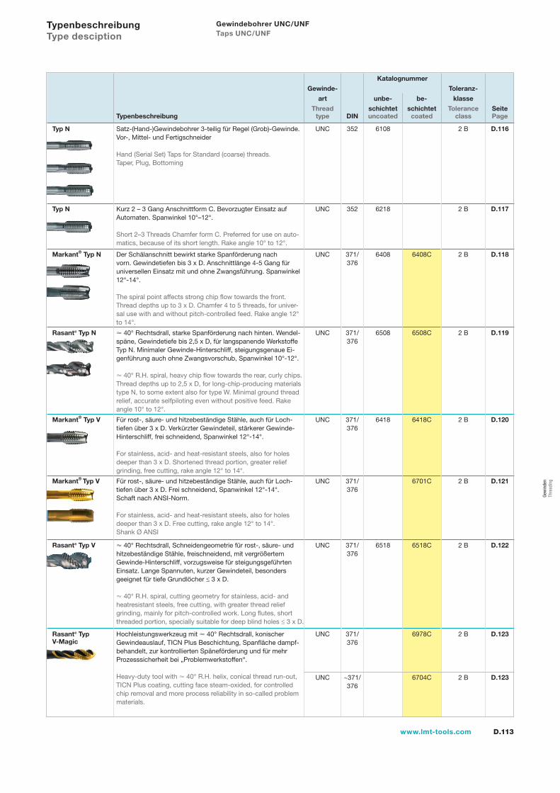
D.113www.lmt-tools.com
Katalognummer
Gewinde- Toleranz-
art unbe- be- klasse
Thread schichtet schichtet Tolerance SeiteTypenbeschreibung type DIN uncoated coated class Page
Typ N Satz-(Hand-)Gewindebohrer 3-teilig für Regel (Grob)-Gewinde.Vor-, Mittel- und Fertigschneider
Hand (Serial Set) Taps for Standard (coarse) threads.Taper, Plug, Bottoming
UNC 352 6108 2 B D.116
Typ N Kurz 2 – 3 Gang Anschnittform C. Bevorzugter Einsatz auf Automaten. Spanwinkel 10°–12°.
Short 2–3 Threads Chamfer form C. Preferred for use on auto-matics, because of its short length. Rake angle 10° to 12°.
UNC 352 6218 2 B D.117
Markant® Typ N Der Schälanschnitt bewirkt starke Spanförderung nach vorn. Gewindetiefen bis 3 x D. Anschnittlänge 4-5 Gang für universellen Einsatz mit und ohne Zwangsführung. Spanwinkel 12°-14°.
The spiral point affects strong chip flow towards the front. Thread depths up to 3 x D. Chamfer 4 to 5 threads, for univer-sal use with and without pitch-controlled feed. Rake angle 12° to 14°.
UNC 371/376
6408 6408C 2 B D.118
Rasant® Typ N 40° Rechtsdrall, starke Spanförderung nach hinten. Wendel-späne, Gewindetiefe bis 2,5 x D, für langspanende Werkstoffe Typ N. Minimaler Gewinde-Hinterschliff, steigungsgenaue Ei-genführung auch ohne Zwangsvorschub, Spanwinkel 10°-12°.
40° R.H. spiral, heavy chip flow towards the rear, curly chips.Thread depths up to 2,5 x D, for long-chip-producing materials type N, to some extent also for type W. Minimal ground thread relief, accurate selfpiloting even without positive feed. Rake angle 10° to 12°.
UNC 371/376
6508 6508C 2 B D.119
Markant® Typ V Für rost-, säure- und hitzebeständige Stähle, auch für Loch-tiefen über 3 x D. Verkürzter Gewindeteil, stärkerer Gewinde-Hinterschliff, frei schneidend, Spanwinkel 12°-14°.
For stainless, acid- and heat-resistant steels, also for holes deeper than 3 x D. Shortened thread portion, greater relief grinding, free cutting, rake angle 12° to 14°.
UNC 371/376
6418 6418C 2 B D.120
Markant® Typ V Für rost-, säure- und hitzebeständige Stähle, auch für Loch-tiefen über 3 x D. Frei schneidend, Spanwinkel 12°-14°.Schaft nach ANSI-Norm.
For stainless, acid- and heat-resistant steels, also for holes deeper than 3 x D. Free cutting, rake angle 12° to 14°. Shank Ø ANSI
UNC 371/376
6701C 2 B D.121
Rasant® Typ V 40° Rechtsdrall, Schneidengeometrie für rost-, säure- und hitzebeständige Stähle, freischneidend, mit vergrößertem Gewinde-Hinterschliff, vorzugsweise für steigungsgeführtenEinsatz. Lange Spannuten, kurzer Gewindeteil, besonders geeignet für tiefe Grundlöcher ≤ 3 x D.
40° R.H. spiral, cutting geometry for stainless, acid- and heatresistant steels, free cutting, with greater thread relief grinding, mainly for pitch-controlled work. Long flutes, short threaded portion, specially suitable for deep blind holes ≤ 3 x D.
UNC 371/376
6518 6518C 2 B D.122
Rasant® Typ V-Magic
Hochleistungswerkzeug mit 40° Rechtsdrall, konischerGewindeauslauf, TICN Plus Beschichtung, Spanfläche dampf-behandelt, zur kontrollierten Späneförderung und für mehr Prozesssicherheit bei „Problemwerkstoffen“.
Heavy-duty tool with 40° R.H. helix, conical thread run-out, TICN Plus coating, cutting face steam-oxided, for controlled chip removal and more process reliability in so-called problem materials.
UNC 371/376
6978C 2 B D.123
UNC ~371/376
6704C 2 B D.123
Typenbeschreibung Type desciption
Gewindebohrer UNC/UNF Taps UNC/UNF
Gew
inde
n Th
read
ing
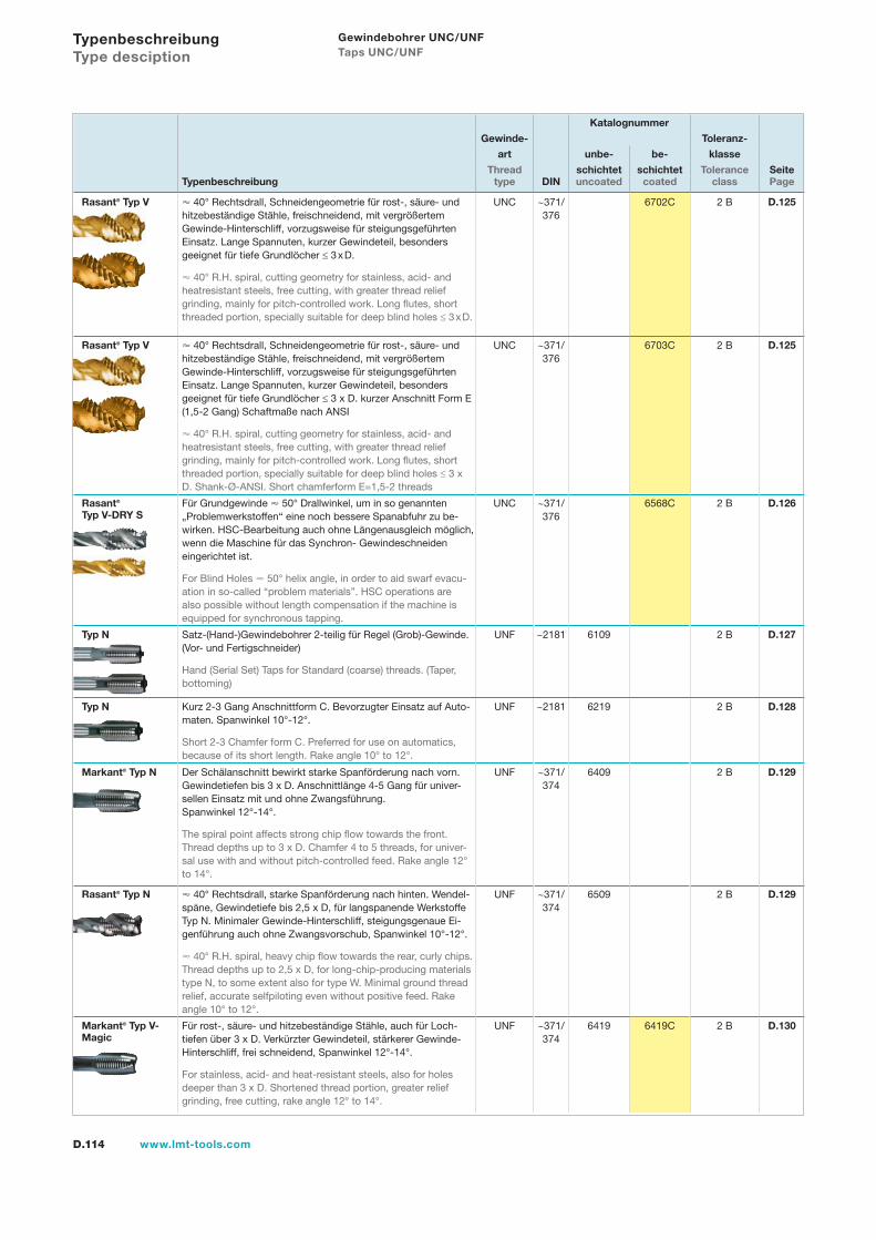
D.114 www.lmt-tools.com
Katalognummer
Gewinde- Toleranz-
art unbe- be- klasse
Thread schichtet schichtet Tolerance SeiteTypenbeschreibung type DIN uncoated coated class Page
Rasant® Typ V 40° Rechtsdrall, Schneidengeometrie für rost-, säure- und hitzebeständige Stähle, freischneidend, mit vergrößertem Gewinde-Hinterschliff, vorzugsweise für steigungsgeführtenEinsatz. Lange Spannuten, kurzer Gewindeteil, besonders geeignet für tiefe Grundlöcher ≤ 3 x D.
40° R.H. spiral, cutting geometry for stainless, acid- and heatresistant steels, free cutting, with greater thread relief grinding, mainly for pitch-controlled work. Long flutes, short threaded portion, specially suitable for deep blind holes ≤ 3 x D.
UNC ~371/376
6702C 2 B D.125
Rasant® Typ V 40° Rechtsdrall, Schneidengeometrie für rost-, säure- und hitzebeständige Stähle, freischneidend, mit vergrößertem Gewinde-Hinterschliff, vorzugsweise für steigungsgeführtenEinsatz. Lange Spannuten, kurzer Gewindeteil, besonders geeignet für tiefe Grundlöcher ≤ 3 x D. kurzer Anschnitt Form E (1,5-2 Gang) Schaftmaße nach ANSI
40° R.H. spiral, cutting geometry for stainless, acid- and heatresistant steels, free cutting, with greater thread relief grinding, mainly for pitch-controlled work. Long flutes, short threaded portion, specially suitable for deep blind holes ≤ 3 x D. Shank-Ø-ANSI. Short chamferform E=1,5-2 threads
UNC ~371/376
6703C 2 B D.125
Rasant® Typ V-DRY S
Für Grundgewinde 50° Drallwinkel, um in so genannten „Problemwerkstoffen“ eine noch bessere Spanabfuhr zu be-wirken. HSC-Bearbeitung auch ohne Längenausgleich möglich, wenn die Maschine für das Synchron- Gewindeschneiden eingerichtet ist.
For Blind Holes 50° helix angle, in order to aid swarf evacu-ation in so-called “problem materials”. HSC operations are also possible without length compensation if the machine is equipped for synchronous tapping.
UNC ~371/376
6568C 2 B D.126
Typ N Satz-(Hand-)Gewindebohrer 2-teilig für Regel (Grob)-Gewinde. (Vor- und Fertigschneider)
Hand (Serial Set) Taps for Standard (coarse) threads. (Taper, bottoming)
UNF ~2181 6109 2 B D.127
Typ N Kurz 2-3 Gang Anschnittform C. Bevorzugter Einsatz auf Auto-maten. Spanwinkel 10°-12°.
Short 2-3 Chamfer form C. Preferred for use on automatics, because of its short length. Rake angle 10° to 12°.
UNF ~2181 6219 2 B D.128
Markant® Typ N Der Schälanschnitt bewirkt starke Spanförderung nach vorn. Gewindetiefen bis 3 x D. Anschnittlänge 4-5 Gang für univer-sellen Einsatz mit und ohne Zwangsführung.Spanwinkel 12°-14°.
The spiral point affects strong chip flow towards the front. Thread depths up to 3 x D. Chamfer 4 to 5 threads, for univer-sal use with and without pitch-controlled feed. Rake angle 12° to 14°.
UNF ~371/374
6409 2 B D.129
Rasant® Typ N 40° Rechtsdrall, starke Spanförderung nach hinten. Wendel-späne, Gewindetiefe bis 2,5 x D, für langspanende Werkstoffe Typ N. Minimaler Gewinde-Hinterschliff, steigungsgenaue Ei-genführung auch ohne Zwangsvorschub, Spanwinkel 10°-12°.
40° R.H. spiral, heavy chip flow towards the rear, curly chips.Thread depths up to 2,5 x D, for long-chip-producing materials type N, to some extent also for type W. Minimal ground thread relief, accurate selfpiloting even without positive feed. Rake angle 10° to 12°.
UNF ~371/374
6509 2 B D.129
Markant® Typ V-Magic
Für rost-, säure- und hitzebeständige Stähle, auch für Loch-tiefen über 3 x D. Verkürzter Gewindeteil, stärkerer Gewinde-Hinterschliff, frei schneidend, Spanwinkel 12°-14°.
For stainless, acid- and heat-resistant steels, also for holes deeper than 3 x D. Shortened thread portion, greater relief grinding, free cutting, rake angle 12° to 14°.
UNF ~371/374
6419 6419C 2 B D.130
Typenbeschreibung Type desciption
Gewindebohrer UNC/UNF Taps UNC/UNF
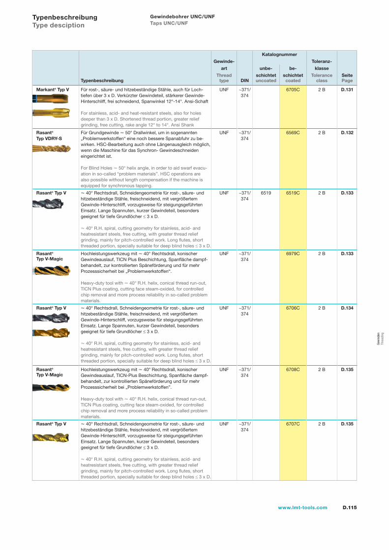
D.115www.lmt-tools.com
Katalognummer
Gewinde- Toleranz-
art unbe- be- klasse
Thread schichtet schichtet Tolerance SeiteTypenbeschreibung type DIN uncoated coated class Page
Markant® Typ V Für rost-, säure- und hitzebeständige Stähle, auch für Loch-tiefen über 3 x D. Verkürzter Gewindeteil, stärkerer Gewinde-Hinterschliff, frei schneidend, Spanwinkel 12°-14°. Ansi-Schaft
For stainless, acid- and heat-resistant steels, also for holes deeper than 3 x D. Shortened thread portion, greater relief grinding, free cutting, rake angle 12° to 14°. Ansi Shank
UNF ~371/374
6705C 2 B D.131
Rasant® Typ VDRY-S
Für Grundgewinde 50° Drallwinkel, um in sogenannten „Problemwerkstoffen“ eine noch bessere Spanabfuhr zu be-wirken. HSC-Bearbeitung auch ohne Längenausgleich möglich, wenn die Maschine für das Synchron- Gewindeschneiden eingerichtet ist.
For Blind Holes 50° helix angle, in order to aid swarf evacu-ation in so-called “problem materials”. HSC operations are also possible without length compensation if the machine is equipped for synchronous tapping.
UNF ~371/374
6569C 2 B D.132
Rasant® Typ V 40° Rechtsdrall, Schneidengeometrie für rost-, säure- und hitzebeständige Stähle, freischneidend, mit vergrößertem Gewinde-Hinterschliff, vorzugsweise für steigungsgeführtenEinsatz. Lange Spannuten, kurzer Gewindeteil, besonders geeignet für tiefe Grundlöcher ≤ 3 x D.
40° R.H. spiral, cutting geometry for stainless, acid- and heatresistant steels, free cutting, with greater thread relief grinding, mainly for pitch-controlled work. Long flutes, short threaded portion, specially suitable for deep blind holes ≤ 3 x D.
UNF ~371/374
6519 6519C 2 B D.133
Rasant® Typ V-Magic
Hochleistungswerkzeug mit 40° Rechtsdrall, konischerGewindeauslauf, TICN Plus Beschichtung, Spanfläche dampf-behandelt, zur kontrollierten Späneförderung und für mehr Prozesssicherheit bei „Problemwerkstoffen“.
Heavy-duty tool with 40° R.H. helix, conical thread run-out, TICN Plus coating, cutting face steam-oxided, for controlled chip removal and more process reliability in so-called problem materials.
UNF ~371/374
6979C 2 B D.133
Rasant® Typ V 40° Rechtsdrall, Schneidengeometrie für rost-, säure- und hitzebeständige Stähle, freischneidend, mit vergrößertem Gewinde-Hinterschliff, vorzugsweise für steigungsgeführtenEinsatz. Lange Spannuten, kurzer Gewindeteil, besonders geeignet für tiefe Grundlöcher ≤ 3 x D.
40° R.H. spiral, cutting geometry for stainless, acid- and heatresistant steels, free cutting, with greater thread relief grinding, mainly for pitch-controlled work. Long flutes, short threaded portion, specially suitable for deep blind holes ≤ 3 x D.
UNF ~371/374
6706C 2 B D.134
Rasant® Typ V-Magic
Hochleistungswerkzeug mit 40° Rechtsdrall, konischer Gewindeauslauf, TICN-Plus Beschichtung, Spanfläche dampf-behandelt, zur kontrollierten Späneförderung und für mehr Prozesssicherheit bei „Problemwerkstoffen”.
Heavy-duty tool with 40° R.H. helix, conical thread run-out, TICN Plus coating, cutting face steam-oxided, for controlled chip removal and more process reliability in so-called problem materials.
UNF ~371/374
6708C 2 B D.135
Rasant® Typ V 40° Rechtsdrall, Schneidengeometrie für rost-, säure- und hitzebeständige Stähle, freischneidend, mit vergrößertem Gewinde-Hinterschliff, vorzugsweise für steigungsgeführtenEinsatz. Lange Spannuten, kurzer Gewindeteil, besonders geeignet für tiefe Grundlöcher ≤ 3 x D.
40° R.H. spiral, cutting geometry for stainless, acid- and heatresistant steels, free cutting, with greater thread relief grinding, mainly for pitch-controlled work. Long flutes, short threaded portion, specially suitable for deep blind holes ≤ 3 x D.
UNF ~371/374
6707C 2 B D.135
Typenbeschreibung Type desciption
Gewindebohrer UNC/UNF Taps UNC/UNF
Gew
inde
n Th
read
ing
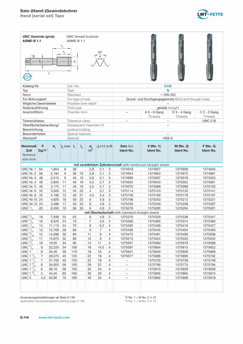
l1
d2
l2
d1
60
P
l3
D.116 www.lmt-tools.com
UNC thread (coarse) ASME-B 1.1
UNC Gewinde (grob) ASME-B 1.1
1)V No. 1 + M No. 2: h 121)V No. 1 + M No. 2: h 12
Anwendungsempfehlungen ab Seite D.136Application recommendations starting page D.136
Satz-(Hand-)GewindebohrerHand (serial set) Taps
Katalog-Nr. Cat.-No. 6108Typ Type NNorm Standard DIN 352Für Bohrungsart For type of hole Grund- und Durchgangsgewinde Blind and through holesMögliche Gewindetiefe Possible bore depth –Nutenausführung Flute type gerade straightAnschnittform Chamfer form – A 5 - 6 Gang
ThreadsD 3 - 4 Gang
ThreadsC 2 - 3 Gang
ThreadsToleranzklasse Tolerance class – – UNC-2 BOberflächenbehandlung/Beschichtung
Subsequent treatment of surface/coating
–
Besonderheiten Special features –Werkstoff Material HSS-E
Nennmaß Zoll
Nominal size inch
PGg/1“
d1 l2 max l1 l3 d2 h91)
h12 z Satz SetIdent No.
V (No. 1)Ident No.
M (No. 2)Ident No.
F (No. 3)Ident No.
mit verstärktem Zylinderschaft with reinforced straight shankUNC Nr. 1 64 1,854 8 36 2,8 2,1 3 1374918 1374927 1374936 1374945UNC Nr. 2 56 2,184 9 36 10 2,8 2,1 3 1374954 1374963 1374972 1374981UNC Nr. 3 48 2,515 9 40 10 2,8 2,1 3 1374990 1375007 1375016 1375025UNC Nr. 4 40 2,845 11 40 18 3,5 2,7 3 1375034 1375043 1375052 1375061UNC Nr. 5 40 3,175 11 40 18 3,5 2,7 3 1375070 1375089 1375098 1375105UNC Nr. 6 32 3,505 12 45 20 4 3,1 3 1375114 1375123 1375132 1375141UNC Nr. 8 32 4,166 13 45 21 4,5 3,4 3 1375150 1375169 1375178 1375187UNC Nr.10 24 4,826 16 50 25 6 4,9 3 1375196 1375203 1375212 1375221UNC Nr.12 24 5,486 17 50 25 6 4,9 3 1375230 1375249 1375258 1375267UNC 1/4 20 6,350 19 56 30 6 4,9 3 1375276 1375285 1375294 1375301
mit Überlaufschaft with standard straight shankUNC 5/16 18 7,938 22 63 6 4,9 3 1375310 1375329 1375338 1375347UNC 3/8 16 9,525 24 70 7 5,5 4 1375356 1375365 1375374 1375383UNC 7/16 14 11,113 24 70 8 6,2 4 1375392 1375409 1375418 1375427UNC 1/2 13 12,700 28 80 9 7 4 1375436 1375445 1375454 1375463UNC 9/16 12 14,288 30 80 11 9 4 1375472 1375481 1375490 1375506UNC 5/8 11 15,875 32 80 12 9 4 1375515 1375524 1375533 1375542UNC 3/4 10 19,05 34 95 14 11 4 1375551 1375560 1375579 1375588UNC 7/8 9 22,225 34 100 18 14,5 4 1375597 1375604 1375613 1375622UNC 1 8 25,40 38 110 18 16 4 1375631 1375640 1375659 1375668UNC 1 1/8 7 28,575 45 125 22 18 4 1375677 1375686 1375695 1375702UNC 1 1/4 7 31,750 45 125 22 18 4 – 1375720 1375739 1375748UNC 1 3/8 6 34,925 56 150 28 22 4 – 1375766 1375775 1375784UNC 1 1/2 6 38,10 56 150 32 24 4 – 1375810 1375829 1375838UNC 1 3/4 5 44,45 65 160 36 29 4 – 1375856 1375865 1375874UNC 2 4,5 50,80 70 180 40 32 4 – 1375892 1375909 1375918
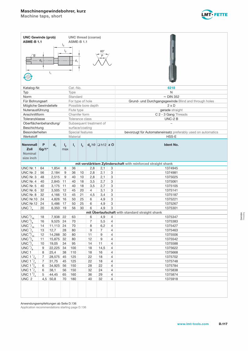
l1
d2
l2
d1
60
P
l3
D.117www.lmt-tools.com
UNC thread (coarse) ASME-B 1.1
UNC Gewinde (grob) ASME-B 1.1
Anwendungsempfehlungen ab Seite D.136Application recommendations starting page D.136
Maschinengewindebohrer, kurzMachine taps, short
Katalog-Nr. Cat.-No. 6218Typ Type NNorm Standard DIN 352Für Bohrungsart For type of hole Grund- und Durchgangsgewinde Blind and through holesMögliche Gewindetiefe Possible bore depth 2 x DNutenausführung Flute type gerade straightAnschnittform Chamfer form C 2 - 3 Gang ThreadsToleranzklasse Tolerance class UNC-2 BOberflächenbehandlung/Beschichtung
Subsequent treatment of surface/coating
–
Besonderheiten Special features bevorzugt für Automateneinsatz preferably used on automaticsWerkstoff Material HSS-E
Nennmaß Zoll
Nominal size inch
PGg/1“
d1 l2 max
l1 l3 d2 h9 h12 z Ident No.
mit verstärktem Zylinderschaft with reinforced straight shankUNC Nr. 1 64 1,854 8 36 2,8 2,1 3 1374945UNC Nr. 2 56 2,184 9 36 10 2,8 2,1 3 1374981UNC Nr. 3 48 2,515 9 40 10 2,8 2,1 3 1375025UNC Nr. 4 40 2,845 11 40 18 3,5 2,7 3 1375061UNC Nr. 5 40 3,175 11 40 18 3,5 2,7 3 1375105UNC Nr. 6 32 3,505 12 45 20 4 3,1 3 1375141UNC Nr. 8 32 4,166 13 45 21 4,5 3,4 3 1375187UNC Nr.10 24 4,826 16 50 25 6 4,9 3 1375221UNC Nr.12 24 5,486 17 50 25 6 4,9 3 1375267UNC 1/4 20 6,350 19 56 30 6 4,9 3 1375301
mit Überlaufschaft with standard straight shankUNC 5/16 18 7,938 22 63 6 4,9 4 1375347UNC 3/8 16 9,525 24 70 7 5,5 4 1375383UNC 7/16 14 11,113 24 70 8 6,2 4 1375427UNC 1/2 13 12,7 28 80 9 7 4 1375463UNC 9/16 12 14,288 30 80 11 9 4 1375506UNC 5/8 11 15,875 32 80 12 9 4 1375542UNC 3/4 10 19,05 34 95 14 11 4 1375588UNC 7/8 9 22,225 34 100 18 14,5 4 1375622UNC 1 8 25,4 38 110 18 16 4 1375668UNC 1 1/8 7 28,575 45 125 22 18 4 1375702UNC 1 1/4 7 31,75 45 125 22 18 4 1375748UNC 1 3/8 6 34,925 56 150 28 22 4 1375784UNC 1 1/2 6 38,1 56 150 32 24 4 1375838UNC 1 3/4 5 44,45 65 160 36 29 4 1375874UNC 2 4,5 50,8 70 180 40 32 4 1375918
Gew
inde
n Th
read
ing
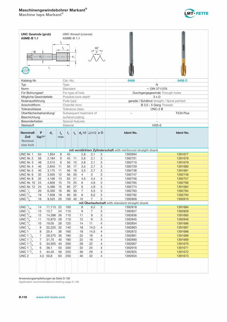
l1
d2
l2
d1
60
P
l3
D.118 www.lmt-tools.com
UNC thread (coarse) ASME-B 1.1
UNC Gewinde (grob) ASME-B 1.1
Anwendungsempfehlungen ab Seite D.136Application recommendations starting page D.136
Maschinengewindebohrer Markant®
Machine taps Markant®
Katalog-Nr. Cat.-No. 6408 6408 CTyp Type NNorm Standard DIN 371/376Für Bohrungsart For type of hole Durchgangsgewinde Through holesMögliche Gewindetiefe Possible bore depth 3 x DNutenausführung Flute type gerade / Schälnut straight / Spiral pointedAnschnittform Chamfer form B 3,5 - 5 Gang ThreadsToleranzklasse Tolerance class UNC-2 BOberflächenbehandlung/Beschichtung
Subsequent treatment of surface/coating
– TiCN Plus
Besonderheiten Special features –Werkstoff Material HSS-E
Nennmaß Zoll
Nominal size inch
PGg/1“
d1 l2 max
l1 l3 d2 h9 h12 z Ident No. Ident No.
mit verstärktem Zylinderschaft with reinforced straight shankUNC Nr. 1 64 1,854 8 45 2,8 2,1 3 1392694 1391677UNC Nr. 2 56 2,184 9 45 11 2,8 2,1 3 1392701 1391678UNC Nr. 3 48 2,515 9 50 15 2,8 2,1 3 1392710 1391679UNC Nr. 4 40 2,845 11 56 17 3,5 2,7 3 1392729 1391680UNC Nr. 5 40 3,175 11 56 18 3,5 2,7 3 1392738 1391681UNC Nr. 6 32 3,505 12 56 20 4 3 3 1392747 1392748UNC Nr. 8 32 4,166 13 63 21 4,5 3,4 3 1392756 1392757UNC Nr. 10 24 4,826 15 70 25 6 4,9 3 1392765 1392766UNC Nr. 12 24 5,486 15 80 27 6 4,9 3 1392774 1391682UNC 1/4 20 6,350 16 80 30 7 5,5 3 1392783 1392784UNC 5/16 18 7,938 18 90 35 8 6,2 3 1392792 1392793UNC 3/8 16 9,525 20 100 40 10 7 3 1392809 1392810
mit Überlaufschaft with standard straight shankUNC 7/16 14 11,113 22 100 8 6,2 3 1392818 1391684UNC 1/2 13 12,7 24 110 9 7 3 1392827 1392828UNC 9/16 12 14,288 26 110 11 9 3 1392836 1391685UNC 5/8 11 15,875 28 110 12 9 3 1392845 1392846UNC 3/4 10 19,05 28 125 14 11 4 1392854 1391686UNC 7/8 9 22,225 32 140 18 14,5 4 1392863 1391687UNC 1 8 25,4 36 160 18 14,5 4 1392872 1391688UNC 1 1/8 7 28,575 36 180 22 18 4 1392881 1391689UNC 1 1/4 7 31,75 40 180 22 18 4 1392890 1391669UNC 1 3/8 6 34,925 40 200 28 22 4 1392907 1391670UNC 1 1/2 6 38,1 50 200 32 24 4 1392916 1391671UNC 1 3/4 5 44,45 56 220 36 29 4 1392925 1391672UNC 2 4,5 50,8 63 250 40 32 4 1392934 1391673
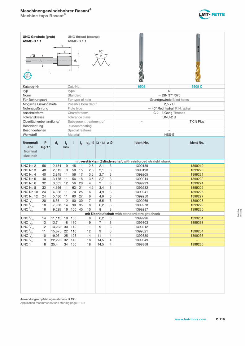
l1
d2
l2
d1
60
P
l3
D.119www.lmt-tools.com
UNC thread (coarse) ASME-B 1.1
UNC Gewinde (grob) ASME-B 1.1
Anwendungsempfehlungen ab Seite D.136Application recommendations starting page D.136
Maschinengewindebohrer Rasant®
Machine taps Rasant®
Katalog-Nr. Cat.-No. 6508 6508 CTyp Type NNorm Standard DIN 371/376Für Bohrungsart For type of hole Grundgewinde Blind holesMögliche Gewindetiefe Possible bore depth 2,5 x DNutenausführung Flute type 40° Rechtsdrall R.H. spiralAnschnittform Chamfer form C 2 - 3 Gang ThreadsToleranzklasse Tolerance class UNC-2 BOberflächenbehandlung/Beschichtung
Subsequent treatment of surface/coating
– TiCN Plus
Besonderheiten Special features –Werkstoff Material HSS-E
Nennmaß Zoll
Nominal size inch
PGg/1“
d1 l2 max
l1 l3 d2 h9 h12 z Ident No. Ident No.
mit verstärktem Zylinderschaft with reinforced straight shankUNC Nr. 2 56 2,184 9 45 11 2,8 2,1 3 1399189 1399219UNC Nr. 3 48 2,515 9 50 15 2,8 2,1 3 1399198 1399220UNC Nr. 4 40 2,845 11 56 17 3,5 2,7 3 1399205 1399221UNC Nr. 5 40 3,175 11 56 18 3,5 2,7 3 1399214 1399222UNC Nr. 6 32 3,505 12 56 20 4 3 3 1399223 1399224UNC Nr. 8 32 4,166 11 63 21 4,5 3,4 3 1399232 1399225UNC Nr. 10 24 4,826 11 70 25 6 4,9 3 1399241 1399226UNC Nr. 12 24 5,486 11 80 27 6 4,9 3 1399250 1399227UNC 1/4 20 6,35 12 80 30 7 5,5 3 1399269 1399228UNC 5/16 18 7,938 14 90 35 8 6,2 3 1399278 1399229UNC 3/8 16 9,525 16 100 40 10 8 3 1399287 1399230
mit Überlaufschaft with standard straight shankUNC 7/16 14 11,113 18 100 8 6,2 3 1399296 1399231UNC 1/2 13 12,7 18 110 9 7 3 1399303 1399233UNC 9/16 12 14,288 30 110 11 9 3 1399312 –UNC 5/8 11 15,875 22 110 12 9 3 1399321 1399234UNC 3/4 10 19,05 25 125 14 11 4 1399330 1399235UNC 7/8 9 22,225 32 140 18 14,5 4 1399349 –UNC 1 8 25,4 34 160 18 14,5 4 1399358 1399236
Gew
inde
n Th
read
ing
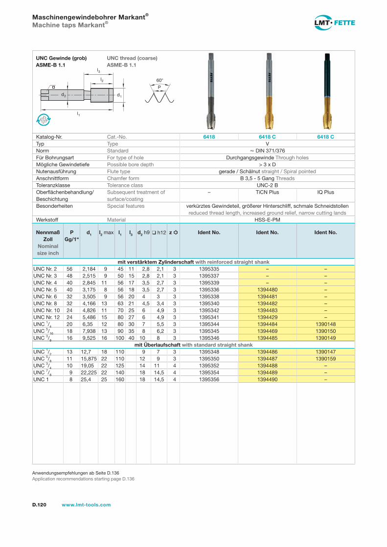
l1
d2
l2
d1
60
P
l3
D.120 www.lmt-tools.com
UNC thread (coarse) ASME-B 1.1
UNC Gewinde (grob) ASME-B 1.1
Anwendungsempfehlungen ab Seite D.136Application recommendations starting page D.136
Maschinengewindebohrer Markant®
Machine taps Markant®
Katalog-Nr. Cat.-No. 6418 6418 C 6418 CTyp Type VNorm Standard DIN 371/376Für Bohrungsart For type of hole Durchgangsgewinde Through holesMögliche Gewindetiefe Possible bore depth > 3 x DNutenausführung Flute type gerade / Schälnut straight / Spiral pointedAnschnittform Chamfer form B 3,5 - 5 Gang ThreadsToleranzklasse Tolerance class UNC-2 BOberflächenbehandlung/Beschichtung
Subsequent treatment of surface/coating
– TiCN Plus IQ Plus
Besonderheiten Special features verkürztes Gewindeteil, größerer Hinterschliff, schmale Schneidstollen reduced thread length, increased ground relief, narrow cutting lands
Werkstoff Material HSS-E-PM
Nennmaß Zoll
Nominal size inch
PGg/1“
d1 l2 max l1 l3 d2 h9 h12 z Ident No. Ident No. Ident No.
mit verstärktem Zylinderschaft with reinforced straight shankUNC Nr. 2 56 2,184 9 45 11 2,8 2,1 3 1395335 – –UNC Nr. 3 48 2,515 9 50 15 2,8 2,1 3 1395337 – –UNC Nr. 4 40 2,845 11 56 17 3,5 2,7 3 1395339 – –UNC Nr. 5 40 3,175 8 56 18 3,5 2,7 3 1395336 1394480 –UNC Nr. 6 32 3,505 9 56 20 4 3 3 1395338 1394481 –UNC Nr. 8 32 4,166 13 63 21 4,5 3,4 3 1395340 1394482 –UNC Nr. 10 24 4,826 11 70 25 6 4,9 3 1395342 1394483 –UNC Nr. 12 24 5,486 15 80 27 6 4,9 3 1395341 1394429 –UNC 1/4 20 6,35 12 80 30 7 5,5 3 1395344 1394484 1390148UNC 5/16 18 7,938 13 90 35 8 6,2 3 1395345 1394469 1390150UNC 3/8 16 9,525 16 100 40 10 8 3 1395346 1394485 1390149
mit Überlaufschaft with standard straight shankUNC 1/2 13 12,7 18 110 9 7 3 1395348 1394486 1390147UNC 5/8 11 15,875 22 110 12 9 3 1395350 1394487 1390159UNC 3/4 10 19,05 22 125 14 11 4 1395352 1394488 –UNC 7/8 9 22,225 22 140 18 14,5 4 1395354 1394489 –UNC 1 8 25,4 25 160 18 14,5 4 1395356 1394490 –
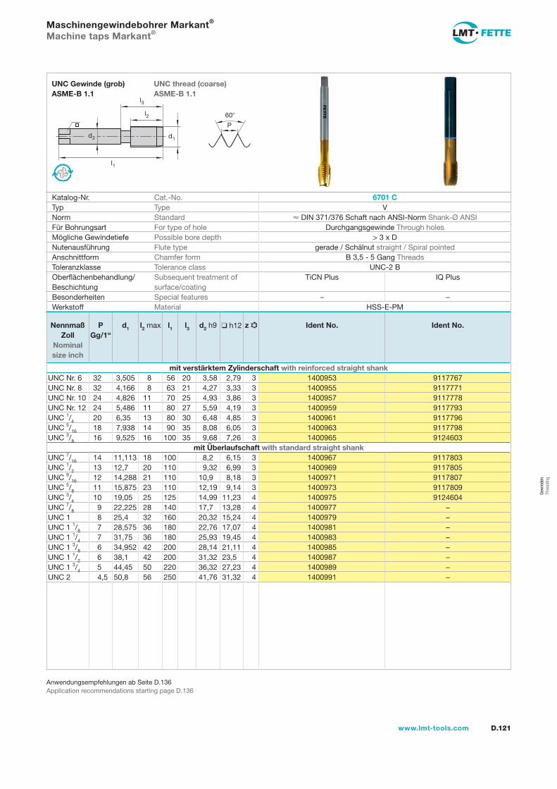
l1
d2
l2
d1
60
P
l3
D.121www.lmt-tools.com
UNC thread (coarse) ASME-B 1.1
UNC Gewinde (grob) ASME-B 1.1
Anwendungsempfehlungen ab Seite D.136Application recommendations starting page D.136
Maschinengewindebohrer Markant®
Machine taps Markant®
Katalog-Nr. Cat.-No. 6701 CTyp Type VNorm Standard DIN 371/376 Schaft nach ANSI-Norm Shank-Ø ANSIFür Bohrungsart For type of hole Durchgangsgewinde Through holesMögliche Gewindetiefe Possible bore depth > 3 x DNutenausführung Flute type gerade / Schälnut straight / Spiral pointedAnschnittform Chamfer form B 3,5 - 5 Gang ThreadsToleranzklasse Tolerance class UNC-2 BOberflächenbehandlung/Beschichtung
Subsequent treatment of surface/coating
TiCN Plus IQ Plus
Besonderheiten Special features – –Werkstoff Material HSS-E-PM
Nennmaß Zoll
Nominal size inch
PGg/1“
d1 l2 max l1 l3 d2 h9 h12 z Ident No. Ident No.
mit verstärktem Zylinderschaft with reinforced straight shankUNC Nr. 6 32 3,505 8 56 20 3,58 2,79 3 1400953 9117767UNC Nr. 8 32 4,166 8 63 21 4,27 3,33 3 1400955 9117771UNC Nr. 10 24 4,826 11 70 25 4,93 3,86 3 1400957 9117778UNC Nr. 12 24 5,486 11 80 27 5,59 4,19 3 1400959 9117793UNC 1/4 20 6,35 13 80 30 6,48 4,85 3 1400961 9117796UNC 5/16 18 7,938 14 90 35 8,08 6,05 3 1400963 9117798UNC 3/8 16 9,525 16 100 35 9,68 7,26 3 1400965 9124603
mit Überlaufschaft with standard straight shankUNC 7/16 14 11,113 18 100 8,2 6,15 3 1400967 9117803UNC 1/2 13 12,7 20 110 9,32 6,99 3 1400969 9117805UNC 9/16 12 14,288 21 110 10,9 8,18 3 1400971 9117807UNC 5/8 11 15,875 23 110 12,19 9,14 3 1400973 9117809UNC 3/4 10 19,05 25 125 14,99 11,23 4 1400975 9124604UNC 7/8 9 22,225 28 140 17,7 13,28 4 1400977 –UNC 1 8 25,4 32 160 20,32 15,24 4 1400979 –UNC 1 1/8 7 28,575 36 180 22,76 17,07 4 1400981 –UNC 1 1/4 7 31,75 36 180 25,93 19,45 4 1400983 –UNC 1 3/8 6 34,952 42 200 28,14 21,11 4 1400985 –UNC 1 1/2 6 38,1 42 200 31,32 23,5 4 1400987 –UNC 1 3/4 5 44,45 50 220 36,32 27,23 4 1400989 –UNC 2 4,5 50,8 56 250 41,76 31,32 4 1400991 –
Gew
inde
n Th
read
ing
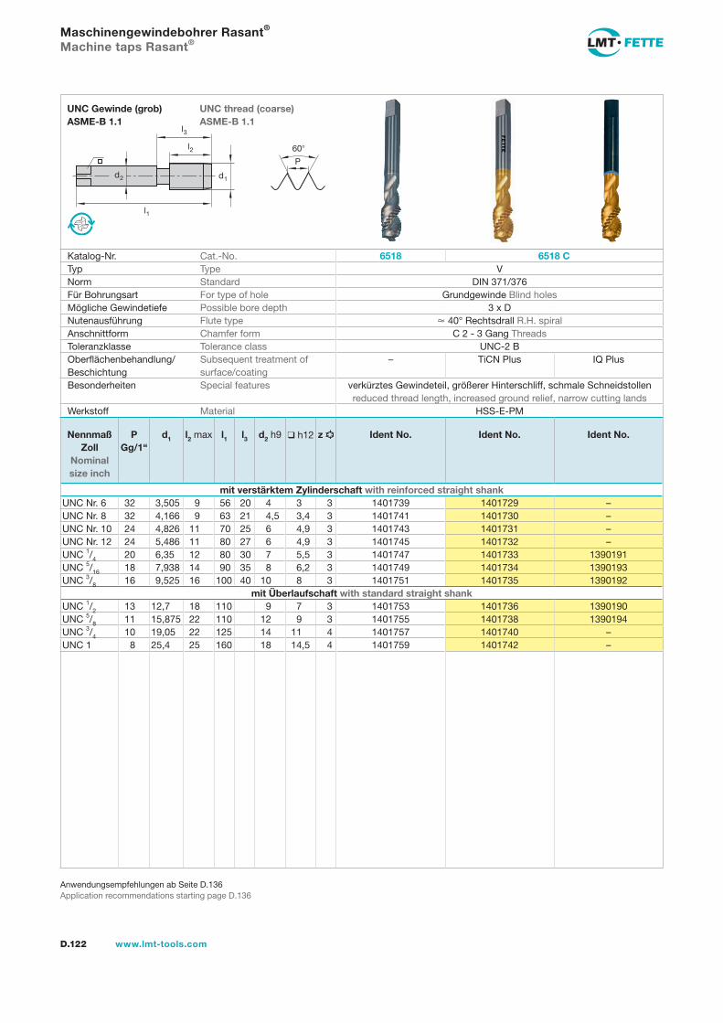
l1
d2
l2
d1
60
P
l3
D.122 www.lmt-tools.com
UNC thread (coarse) ASME-B 1.1
UNC Gewinde (grob) ASME-B 1.1
Anwendungsempfehlungen ab Seite D.136Application recommendations starting page D.136
Maschinengewindebohrer Rasant®
Machine taps Rasant®
Katalog-Nr. Cat.-No. 6518 6518 CTyp Type VNorm Standard DIN 371/376Für Bohrungsart For type of hole Grundgewinde Blind holesMögliche Gewindetiefe Possible bore depth 3 x DNutenausführung Flute type 40° Rechtsdrall R.H. spiralAnschnittform Chamfer form C 2 - 3 Gang ThreadsToleranzklasse Tolerance class UNC-2 BOberflächenbehandlung/Beschichtung
Subsequent treatment of surface/coating
– TiCN Plus IQ Plus
Besonderheiten Special features verkürztes Gewindeteil, größerer Hinterschliff, schmale Schneidstollen reduced thread length, increased ground relief, narrow cutting lands
Werkstoff Material HSS-E-PM
Nennmaß Zoll
Nominal size inch
PGg/1“
d1 l2 max l1 l3 d2 h9 h12 z Ident No. Ident No. Ident No.
mit verstärktem Zylinderschaft with reinforced straight shankUNC Nr. 6 32 3,505 9 56 20 4 3 3 1401739 1401729 –UNC Nr. 8 32 4,166 9 63 21 4,5 3,4 3 1401741 1401730 –UNC Nr. 10 24 4,826 11 70 25 6 4,9 3 1401743 1401731 –UNC Nr. 12 24 5,486 11 80 27 6 4,9 3 1401745 1401732 –UNC 1/4 20 6,35 12 80 30 7 5,5 3 1401747 1401733 1390191UNC 5/16 18 7,938 14 90 35 8 6,2 3 1401749 1401734 1390193UNC 3/8 16 9,525 16 100 40 10 8 3 1401751 1401735 1390192
mit Überlaufschaft with standard straight shankUNC 1/2 13 12,7 18 110 9 7 3 1401753 1401736 1390190UNC 5/8 11 15,875 22 110 12 9 3 1401755 1401738 1390194UNC 3/4 10 19,05 22 125 14 11 4 1401757 1401740 –UNC 1 8 25,4 25 160 18 14,5 4 1401759 1401742 –
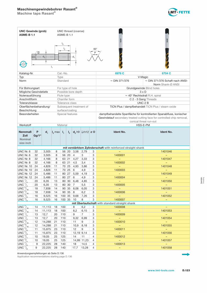
l1
d2
l2
d1
60
P
l3
D.123www.lmt-tools.com
UNC thread (coarse) ASME-B 1.1
UNC Gewinde (grob) ASME-B 1.1
Anwendungsempfehlungen ab Seite D.136Application recommendations starting page D.136
Maschinengewindebohrer Rasant®
Machine taps Rasant®
Katalog-Nr. Cat.-No. 6978 C 6704 CTyp Type V-MagicNorm Standard DIN 371/376 DIN 371/376 Schaft nach ANSI-
Norm Shank-Ø ANSIFür Bohrungsart For type of hole Grundgewinde Blind holesMögliche Gewindetiefe Possible bore depth 3 x DNutenausführung Flute type 40° Rechtsdrall R.H. spiralAnschnittform Chamfer form C 2 - 3 Gang ThreadsToleranzklasse Tolerance class UNC-2 BOberflächenbehandlung/Beschichtung
Subsequent treatment of surface/coating
TiCN Plus / dampfbehandelt TiCN Plus / steam oxide
Besonderheiten Special features dampfbehandelte Spanfläche für kontrollierten Spanabfluss, konischer Gewindelauf secondary treated cutting face for controlled chip removal,
conical threat run-outWerkstoff Material HSS-E-PM
Nennmaß Zoll
Nominal size inch
PGg/1“
d1 l2 max l1 l3 d2 h9 h12 z Ident No. Ident No.
mit verstärktem Zylinderschaft with reinforced straight shankUNC Nr. 6 32 3,505 8 56 20 3,58 2,79 3 – 1401046UNC Nr. 6 32 3,505 8 56 20 4 3 3 1400001 –UNC Nr. 8 32 4,166 8 63 21 4,27 3,33 3 – 1401047UNC Nr. 8 32 4,166 8 63 21 4,5 3,4 3 1400002 –UNC Nr. 10 24 4,826 11 70 25 4,93 3,86 3 – 1401048UNC Nr. 10 24 4,826 11 70 25 6 4,9 3 1400003 –UNC Nr. 12 24 5,486 11 80 27 5,59 4,19 3 – 1401049UNC Nr. 12 24 5,486 11 80 27 6 4,9 3 1400004 –UNC 1/4 20 6,35 13 80 30 6,48 4,85 3 – 1401050UNC 1/4 20 6,35 13 80 30 7 5,5 3 1400005 –UNC 5/16 18 7,938 14 90 35 8,08 6,05 3 – 1401051UNC 5/16 18 7,938 14 90 35 8 6,2 3 1400006 –UNC 3/8 16 9,525 16 100 35 9,68 7,26 3 – 1401052UNC 3/8 16 9,525 16 100 35 10 8 3 1400007 –
mit Überlaufschaft with standard straight shankUNC 7/16 14 11,113 18 100 8 6,2 3 1400008 –UNC 7/16 14 11,113 18 100 8,2 6,15 3 – 1401053UNC 1/2 13 12,7 20 110 9 7 3 1400009 –UNC 1/2 13 12,7 20 110 9,32 6,99 3 – 1401054UNC 9/16 12 14,288 21 110 11 9 3 1400010 –UNC 9/16 12 14,288 21 110 10,9 8,18 3 – 1401055UNC 5/8 11 15,875 23 110 12 9 3 1400011 –UNC 5/8 11 15,875 23 110 12,19 9,14 3 – 1401056UNC 3/4 10 19,05 25 125 14 11 4 1400012 –UNC 3/4 10 19,05 25 125 14,99 11,23 4 – 1401057UNC 7/8 9 22,225 28 140 18 14,5 4 1400013 –UNC 7/8 9 22,225 28 140 17,7 13,28 4 – 1401058
Gew
inde
n Th
read
ing
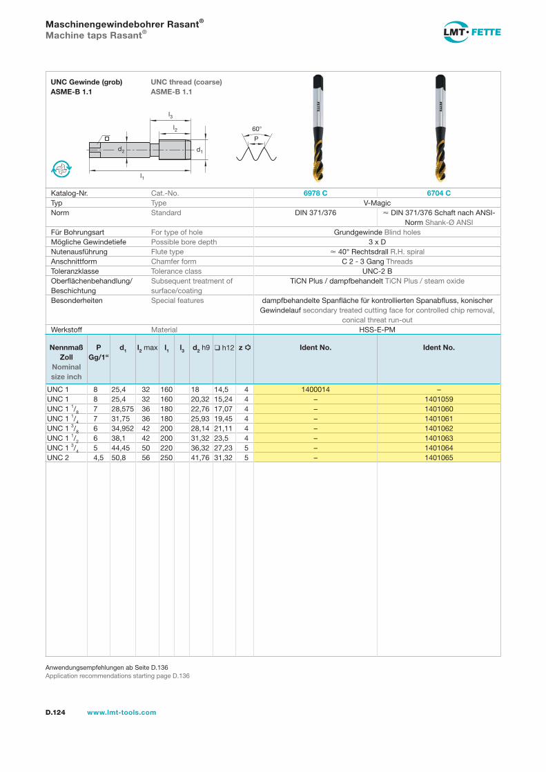
l1
d2
l2
d1
60
P
l3
D.124 www.lmt-tools.com
UNC thread (coarse) ASME-B 1.1
UNC Gewinde (grob) ASME-B 1.1
Anwendungsempfehlungen ab Seite D.136Application recommendations starting page D.136
Maschinengewindebohrer Rasant®
Machine taps Rasant®
Katalog-Nr. Cat.-No. 6978 C 6704 CTyp Type V-MagicNorm Standard DIN 371/376 DIN 371/376 Schaft nach ANSI-
Norm Shank-Ø ANSIFür Bohrungsart For type of hole Grundgewinde Blind holesMögliche Gewindetiefe Possible bore depth 3 x DNutenausführung Flute type 40° Rechtsdrall R.H. spiralAnschnittform Chamfer form C 2 - 3 Gang ThreadsToleranzklasse Tolerance class UNC-2 BOberflächenbehandlung/Beschichtung
Subsequent treatment of surface/coating
TiCN Plus / dampfbehandelt TiCN Plus / steam oxide
Besonderheiten Special features dampfbehandelte Spanfläche für kontrollierten Spanabfluss, konischer Gewindelauf secondary treated cutting face for controlled chip removal,
conical threat run-outWerkstoff Material HSS-E-PM
Nennmaß Zoll
Nominal size inch
PGg/1“
d1 l2 max l1 l3 d2 h9 h12 z Ident No. Ident No.
UNC 1 8 25,4 32 160 18 14,5 4 1400014 –UNC 1 8 25,4 32 160 20,32 15,24 4 – 1401059UNC 1 1/8 7 28,575 36 180 22,76 17,07 4 – 1401060UNC 1 1/4 7 31,75 36 180 25,93 19,45 4 – 1401061UNC 1 3/8 6 34,952 42 200 28,14 21,11 4 – 1401062UNC 1 1/2 6 38,1 42 200 31,32 23,5 4 – 1401063UNC 1 3/4 5 44,45 50 220 36,32 27,23 5 – 1401064UNC 2 4,5 50,8 56 250 41,76 31,32 5 – 1401065
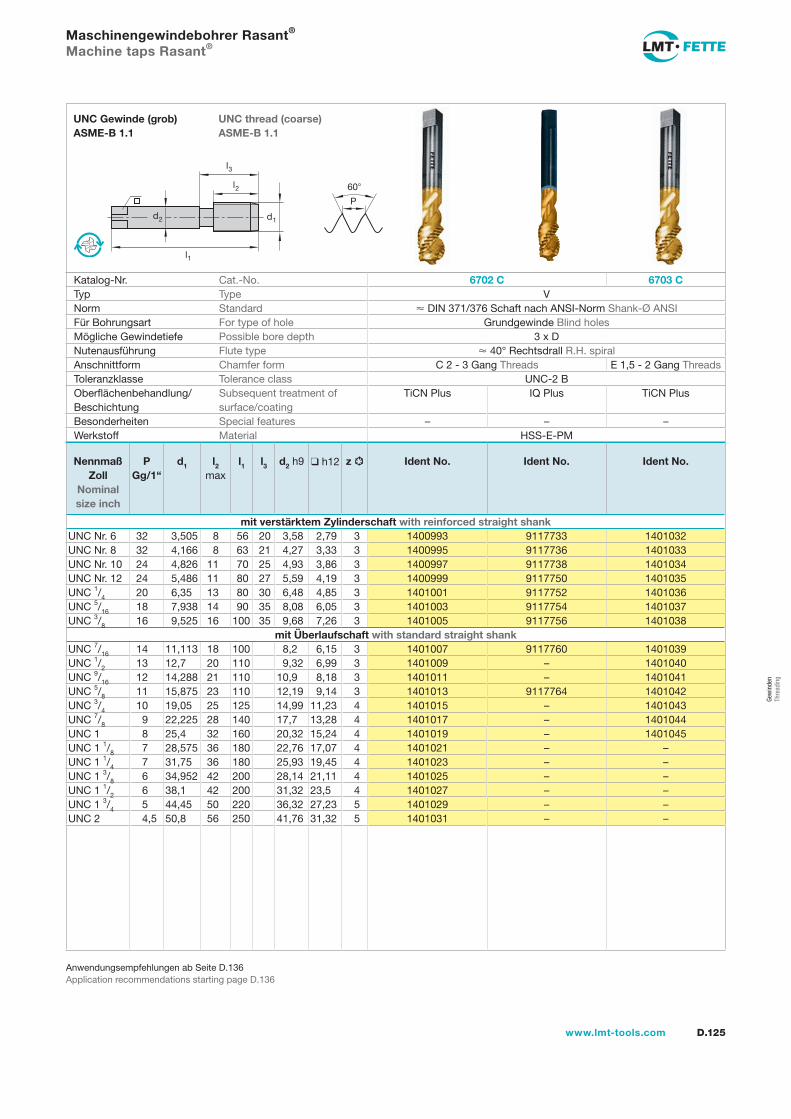
l1
d2
l2
d1
60
P
l3
D.125www.lmt-tools.com
UNC thread (coarse) ASME-B 1.1
UNC Gewinde (grob) ASME-B 1.1
Anwendungsempfehlungen ab Seite D.136Application recommendations starting page D.136
Maschinengewindebohrer Rasant®
Machine taps Rasant®
Katalog-Nr. Cat.-No. 6702 C 6703 CTyp Type VNorm Standard DIN 371/376 Schaft nach ANSI-Norm Shank-Ø ANSIFür Bohrungsart For type of hole Grundgewinde Blind holesMögliche Gewindetiefe Possible bore depth 3 x DNutenausführung Flute type 40° Rechtsdrall R.H. spiralAnschnittform Chamfer form C 2 - 3 Gang Threads E 1,5 - 2 Gang ThreadsToleranzklasse Tolerance class UNC-2 BOberflächenbehandlung/Beschichtung
Subsequent treatment of surface/coating
TiCN Plus IQ Plus TiCN Plus
Besonderheiten Special features – – –Werkstoff Material HSS-E-PM
Nennmaß Zoll
Nominal size inch
PGg/1“
d1 l2 max
l1 l3 d2 h9 h12 z Ident No. Ident No. Ident No.
mit verstärktem Zylinderschaft with reinforced straight shankUNC Nr. 6 32 3,505 8 56 20 3,58 2,79 3 1400993 9117733 1401032UNC Nr. 8 32 4,166 8 63 21 4,27 3,33 3 1400995 9117736 1401033UNC Nr. 10 24 4,826 11 70 25 4,93 3,86 3 1400997 9117738 1401034UNC Nr. 12 24 5,486 11 80 27 5,59 4,19 3 1400999 9117750 1401035UNC 1/4 20 6,35 13 80 30 6,48 4,85 3 1401001 9117752 1401036UNC 5/16 18 7,938 14 90 35 8,08 6,05 3 1401003 9117754 1401037UNC 3/8 16 9,525 16 100 35 9,68 7,26 3 1401005 9117756 1401038
mit Überlaufschaft with standard straight shankUNC 7/16 14 11,113 18 100 8,2 6,15 3 1401007 9117760 1401039UNC 1/2 13 12,7 20 110 9,32 6,99 3 1401009 – 1401040UNC 9/16 12 14,288 21 110 10,9 8,18 3 1401011 – 1401041UNC 5/8 11 15,875 23 110 12,19 9,14 3 1401013 9117764 1401042UNC 3/4 10 19,05 25 125 14,99 11,23 4 1401015 – 1401043UNC 7/8 9 22,225 28 140 17,7 13,28 4 1401017 – 1401044UNC 1 8 25,4 32 160 20,32 15,24 4 1401019 – 1401045UNC 1 1/8 7 28,575 36 180 22,76 17,07 4 1401021 – –UNC 1 1/4 7 31,75 36 180 25,93 19,45 4 1401023 – –UNC 1 3/8 6 34,952 42 200 28,14 21,11 4 1401025 – –UNC 1 1/2 6 38,1 42 200 31,32 23,5 4 1401027 – –UNC 1 3/4 5 44,45 50 220 36,32 27,23 5 1401029 – –UNC 2 4,5 50,8 56 250 41,76 31,32 5 1401031 – –
Gew
inde
n Th
read
ing
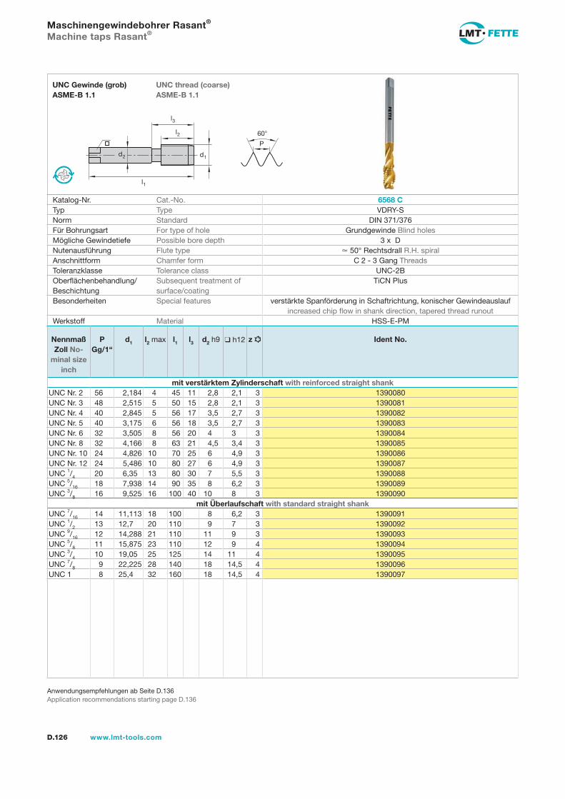
D.126 www.lmt-tools.com
l1
d2
l2
d1
60
P
l3
UNC thread (coarse) ASME-B 1.1
UNC Gewinde (grob) ASME-B 1.1
Anwendungsempfehlungen ab Seite D.136Application recommendations starting page D.136
Maschinengewindebohrer Rasant®
Machine taps Rasant®
Katalog-Nr. Cat.-No. 6568 CTyp Type VDRY-SNorm Standard DIN 371/376Für Bohrungsart For type of hole Grundgewinde Blind holesMögliche Gewindetiefe Possible bore depth 3 x DNutenausführung Flute type 50° Rechtsdrall R.H. spiralAnschnittform Chamfer form C 2 - 3 Gang ThreadsToleranzklasse Tolerance class UNC-2BOberflächenbehandlung/Beschichtung
Subsequent treatment of surface/coating
TiCN Plus
Besonderheiten Special features verstärkte Spanförderung in Schaftrichtung, konischer Gewindeauslauf increased chip flow in shank direction, tapered thread runout
Werkstoff Material HSS-E-PM
Nennmaß Zoll No-
minal size inch
PGg/1“
d1 l2 max l1 l3 d2 h9 h12 z Ident No.
mit verstärktem Zylinderschaft with reinforced straight shankUNC Nr. 2 56 2,184 4 45 11 2,8 2,1 3 1390080UNC Nr. 3 48 2,515 5 50 15 2,8 2,1 3 1390081UNC Nr. 4 40 2,845 5 56 17 3,5 2,7 3 1390082UNC Nr. 5 40 3,175 6 56 18 3,5 2,7 3 1390083UNC Nr. 6 32 3,505 8 56 20 4 3 3 1390084UNC Nr. 8 32 4,166 8 63 21 4,5 3,4 3 1390085UNC Nr. 10 24 4,826 10 70 25 6 4,9 3 1390086UNC Nr. 12 24 5,486 10 80 27 6 4,9 3 1390087UNC 1/4 20 6,35 13 80 30 7 5,5 3 1390088UNC 5/16 18 7,938 14 90 35 8 6,2 3 1390089UNC 3/8 16 9,525 16 100 40 10 8 3 1390090
mit Überlaufschaft with standard straight shankUNC 7/16 14 11,113 18 100 8 6,2 3 1390091UNC 1/2 13 12,7 20 110 9 7 3 1390092UNC 9/16 12 14,288 21 110 11 9 3 1390093UNC 5/8 11 15,875 23 110 12 9 4 1390094UNC 3/4 10 19,05 25 125 14 11 4 1390095UNC 7/8 9 22,225 28 140 18 14,5 4 1390096UNC 1 8 25,4 32 160 18 14,5 4 1390097
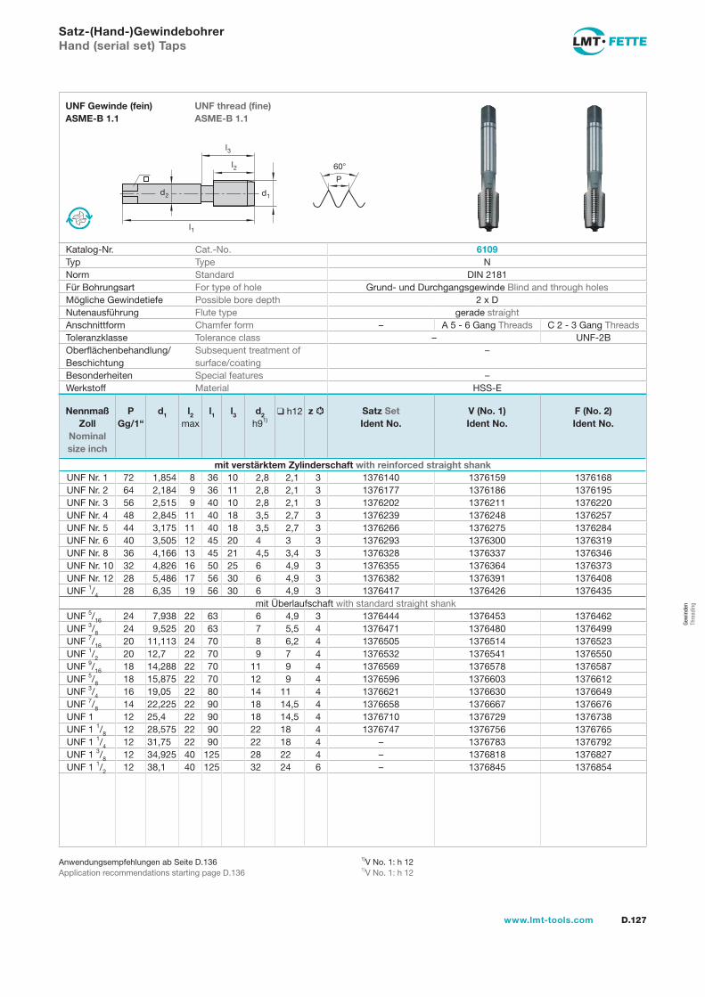
l1
d2
l2
d1
60
P
l3
D.127www.lmt-tools.com
UNF thread (fine) ASME-B 1.1
UNF Gewinde (fein) ASME-B 1.1
1)V No. 1: h 121)V No. 1: h 12
Anwendungsempfehlungen ab Seite D.136Application recommendations starting page D.136
Satz-(Hand-)GewindebohrerHand (serial set) Taps
Katalog-Nr. Cat.-No. 6109Typ Type NNorm Standard DIN 2181Für Bohrungsart For type of hole Grund- und Durchgangsgewinde Blind and through holesMögliche Gewindetiefe Possible bore depth 2 x DNutenausführung Flute type gerade straightAnschnittform Chamfer form – A 5 - 6 Gang Threads C 2 - 3 Gang ThreadsToleranzklasse Tolerance class – UNF-2BOberflächenbehandlung/Beschichtung
Subsequent treatment of surface/coating
–
Besonderheiten Special features –Werkstoff Material HSS-E
Nennmaß Zoll
Nominal size inch
PGg/1“
d1 l2 max
l1 l3 d2 h91)
h12 z Satz SetIdent No.
V (No. 1)Ident No.
F (No. 2)Ident No.
mit verstärktem Zylinderschaft with reinforced straight shankUNF Nr. 1 72 1,854 8 36 10 2,8 2,1 3 1376140 1376159 1376168UNF Nr. 2 64 2,184 9 36 11 2,8 2,1 3 1376177 1376186 1376195UNF Nr. 3 56 2,515 9 40 10 2,8 2,1 3 1376202 1376211 1376220UNF Nr. 4 48 2,845 11 40 18 3,5 2,7 3 1376239 1376248 1376257UNF Nr. 5 44 3,175 11 40 18 3,5 2,7 3 1376266 1376275 1376284UNF Nr. 6 40 3,505 12 45 20 4 3 3 1376293 1376300 1376319UNF Nr. 8 36 4,166 13 45 21 4,5 3,4 3 1376328 1376337 1376346UNF Nr. 10 32 4,826 16 50 25 6 4,9 3 1376355 1376364 1376373UNF Nr. 12 28 5,486 17 56 30 6 4,9 3 1376382 1376391 1376408UNF 1/4 28 6,35 19 56 30 6 4,9 3 1376417 1376426 1376435
mit Überlaufschaft with standard straight shankUNF 5/16 24 7,938 22 63 6 4,9 3 1376444 1376453 1376462UNF 3/8 24 9,525 20 63 7 5,5 4 1376471 1376480 1376499UNF 7/16 20 11,113 24 70 8 6,2 4 1376505 1376514 1376523UNF 1/2 20 12,7 22 70 9 7 4 1376532 1376541 1376550UNF 9/16 18 14,288 22 70 11 9 4 1376569 1376578 1376587UNF 5/8 18 15,875 22 70 12 9 4 1376596 1376603 1376612UNF 3/4 16 19,05 22 80 14 11 4 1376621 1376630 1376649UNF 7/8 14 22,225 22 90 18 14,5 4 1376658 1376667 1376676UNF 1 12 25,4 22 90 18 14,5 4 1376710 1376729 1376738UNF 1 1/8 12 28,575 22 90 22 18 4 1376747 1376756 1376765UNF 1 1/4 12 31,75 22 90 22 18 4 – 1376783 1376792UNF 1 3/8 12 34,925 40 125 28 22 4 – 1376818 1376827UNF 1 1/2 12 38,1 40 125 32 24 6 – 1376845 1376854
Gew
inde
n Th
read
ing
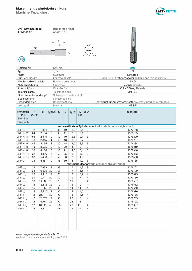
l1
d2
l2
d1
60
P
l3
D.128 www.lmt-tools.com
UNF thread (fine) ASME-B 1.1
UNF Gewinde (fein) ASME-B 1.1
Anwendungsempfehlungen ab Seite D.136Application recommendations starting page D.136
Maschinengewindebohrer, kurzMachine Taps, short
Katalog-Nr. Cat.-No. 6219Typ Type NNorm Standard DIN 2181Für Bohrungsart For type of hole Grund- und Durchgangsgewinde Blind and through holesMögliche Gewindetiefe Possible bore depth 2 x DNutenausführung Flute type gerade straightAnschnittform Chamfer form C 2 - 3 Gang ThreadsToleranzklasse Tolerance class UNF-2BOberflächenbehandlung/Beschichtung
Subsequent treatment of surface/coating
–
Besonderheiten Special features bevorzugt für Automateneinsatz preferably used on automaticsWerkstoff Material HSS-E
Nennmaß Zoll
Nominal size inch
PGg/1“
d1 l2 max l1 l3 d2 h9 h12
z Ident No.
mit verstärktem Zylinderschaft with reinforced straight shankUNF Nr. 1 72 1,854 8 36 10 2,8 2,1 3 1376168UNF Nr. 2 64 2,184 9 36 11 2,8 2,1 3 1376195UNF Nr. 3 56 2,515 9 40 10 2,8 2,1 3 1376220UNF Nr. 4 48 2,845 11 40 18 3,5 2,7 3 1376257UNF Nr. 5 44 3,175 11 40 18 3,5 2,7 3 1376284UNF Nr. 6 40 3,505 12 45 20 4 3 3 1376319UNF Nr. 8 36 4,166 13 45 21 4,5 3,4 3 1376346UNF Nr. 10 32 4,826 16 50 25 6 4,9 3 1376373UNF Nr. 12 28 5,486 17 56 30 6 4,9 3 1376408UNF 1/4 28 6,35 19 56 30 6 4,9 3 1376435
mit Überlaufschaft with standard straight shankUNF 5/16 24 7,938 22 63 6 4,9 3 1376462UNF 3/8 24 9,525 20 63 7 5,5 4 1376499UNF 7/16 20 11,113 24 70 8 6,2 4 1376523UNF 1/2 20 12,7 22 70 9 7 4 1376550UNF 9/16 18 14,288 22 70 11 9 4 1376587UNF 5/8 18 15,875 22 70 12 9 4 1376612UNF 3/4 16 19,05 22 80 14 11 4 1376649UNF 7/8 14 22,225 22 90 18 14,5 4 1376676UNF 1 12 25,4 22 90 18 14,5 4 1376738UNF 1 1/8 12 28,575 22 90 22 18 4 1376765UNF 1 1/4 12 31,75 22 90 22 18 4 1376792UNF 1 3/8 12 34,925 40 125 28 22 4 1376827UNF 1 1/2 12 38,1 40 125 32 24 6 1376854
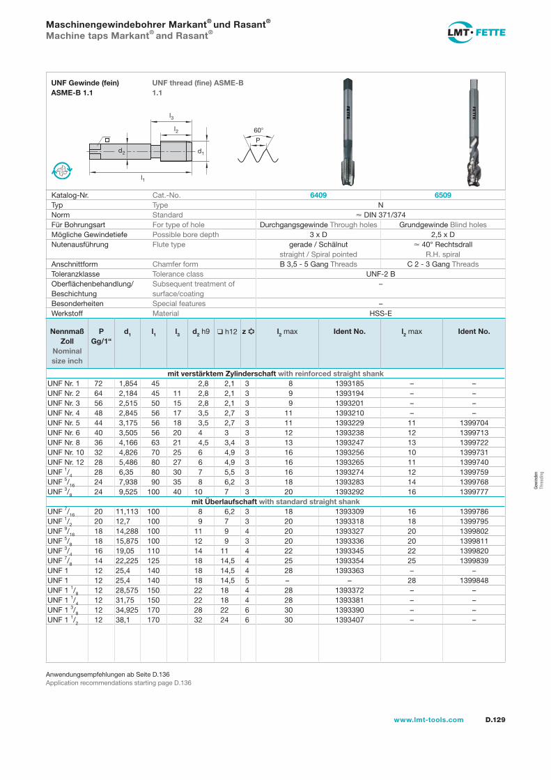
l1
d2
l2
d1
60
P
l3
D.129www.lmt-tools.com
UNF thread (fine) ASME-B 1.1
UNF Gewinde (fein) ASME-B 1.1
Anwendungsempfehlungen ab Seite D.136Application recommendations starting page D.136
Maschinengewindebohrer Markant® und Rasant®
Machine taps Markant® and Rasant®
Katalog-Nr. Cat.-No. 6409 6509Typ Type NNorm Standard DIN 371/374Für Bohrungsart For type of hole Durchgangsgewinde Through holes Grundgewinde Blind holesMögliche Gewindetiefe Possible bore depth 3 x D 2,5 x DNutenausführung Flute type gerade / Schälnut
straight / Spiral pointed 40° Rechtsdrall
R.H. spiralAnschnittform Chamfer form B 3,5 - 5 Gang Threads C 2 - 3 Gang ThreadsToleranzklasse Tolerance class UNF-2 BOberflächenbehandlung/Beschichtung
Subsequent treatment of surface/coating
–
Besonderheiten Special features –Werkstoff Material HSS-E
Nennmaß Zoll
Nominal size inch
PGg/1“
d1 l1 l3 d2 h9 h12 z l2 max Ident No. l2 max Ident No.
mit verstärktem Zylinderschaft with reinforced straight shankUNF Nr. 1 72 1,854 45 2,8 2,1 3 8 1393185 – –UNF Nr. 2 64 2,184 45 11 2,8 2,1 3 9 1393194 – –UNF Nr. 3 56 2,515 50 15 2,8 2,1 3 9 1393201 – –UNF Nr. 4 48 2,845 56 17 3,5 2,7 3 11 1393210 – –UNF Nr. 5 44 3,175 56 18 3,5 2,7 3 11 1393229 11 1399704UNF Nr. 6 40 3,505 56 20 4 3 3 12 1393238 12 1399713UNF Nr. 8 36 4,166 63 21 4,5 3,4 3 13 1393247 13 1399722UNF Nr. 10 32 4,826 70 25 6 4,9 3 16 1393256 10 1399731UNF Nr. 12 28 5,486 80 27 6 4,9 3 16 1393265 11 1399740UNF 1/4 28 6,35 80 30 7 5,5 3 16 1393274 12 1399759UNF 5/16 24 7,938 90 35 8 6,2 3 18 1393283 14 1399768UNF 3/8 24 9,525 100 40 10 7 3 20 1393292 16 1399777
mit Überlaufschaft with standard straight shankUNF 7/16 20 11,113 100 8 6,2 3 18 1393309 16 1399786UNF 1/2 20 12,7 100 9 7 3 20 1393318 18 1399795UNF 9/16 18 14,288 100 11 9 4 20 1393327 20 1399802UNF 5/8 18 15,875 100 12 9 3 20 1393336 20 1399811UNF 3/4 16 19,05 110 14 11 4 22 1393345 22 1399820UNF 7/8 14 22,225 125 18 14,5 4 25 1393354 25 1399839UNF 1 12 25,4 140 18 14,5 4 28 1393363 – –UNF 1 12 25,4 140 18 14,5 5 – – 28 1399848UNF 1 1/8 12 28,575 150 22 18 4 28 1393372 – –UNF 1 1/4 12 31,75 150 22 18 4 28 1393381 – –UNF 1 3/8 12 34,925 170 28 22 6 30 1393390 – –UNF 1 1/2 12 38,1 170 32 24 6 30 1393407 – –
Gew
inde
n Th
read
ing
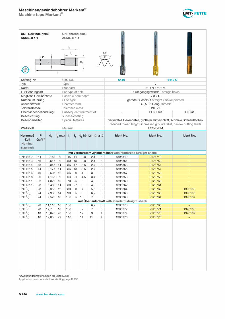
l1
d2
l2
d1
60
P
l3
D.130 www.lmt-tools.com
UNF thread (fine) ASME-B 1.1
UNF Gewinde (fein) ASME-B 1.1
Anwendungsempfehlungen ab Seite D.136Application recommendations starting page D.136
Maschinengewindebohrer Markant®
Machine taps Markant®
Katalog-Nr. Cat.-No. 6419 6419 CTyp Type VNorm Standard DIN 371/374Für Bohrungsart For type of hole Durchgangsgewinde Through holesMögliche Gewindetiefe Possible bore depth > 3 x DNutenausführung Flute type gerade / Schälnut straight / Spiral pointedAnschnittform Chamfer form B 3,5 - 5 Gang ThreadsToleranzklasse Tolerance class UNF-2 BOberflächenbehandlung/Beschichtung
Subsequent treatment of surface/coating
– TiCN Plus IQ Plus
Besonderheiten Special features verkürztes Gewindeteil, größerer Hinterschliff, schmale Schneidstollen reduced thread length, increased ground relief, narrow cutting lands
Werkstoff Material HSS-E-PM
Nennmaß Zoll
Nominal size inch
PGg/1“
d1 l2 max l1 l3 d2 h9 h12 z Ident No. Ident No. Ident No.
mit verstärktem Zylinderschaft with reinforced straight shankUNF Nr. 2 64 2,184 9 45 11 2,8 2,1 3 1395349 9128749 –UNF Nr. 3 56 2,515 9 50 15 2,8 2,1 3 1395351 9128750 –UNF Nr. 4 48 2,845 11 56 17 3,5 2,7 3 1395353 9128754 –UNF Nr. 5 44 3,175 11 56 18 3,5 2,7 3 1395355 9128757 –UNF Nr. 6 40 3,505 12 56 20 4 3 3 1395357 9128758 –UNF Nr. 8 36 4,166 9 63 21 4,5 3,4 3 1395358 9128759 –UNF Nr. 10 32 4,826 10 70 25 6 4,9 3 1395360 9128760 –UNF Nr. 12 28 5,486 11 80 27 6 4,9 3 1395362 9128761 –UNF 1/4 28 6,35 12 80 30 7 5,5 3 1395364 9128762 1390166UNF 5/16 24 7,938 14 90 35 8 6,2 3 1395366 9128763 1390168UNF 3/8 24 9,525 16 100 35 10 7 3 1395368 9128764 1390167
mit Überlaufschaft with standard straight shankUNF 7/16 20 11,113 16 100 8 6,2 3 1395370 9128765 –UNF 1/2 20 12,7 18 100 9 7 3 1395372 9128771 1390165UNF 5/8 18 15,875 20 100 12 9 4 1395374 9128773 1390169UNF 3/4 16 19,05 22 110 14 11 4 1395376 9128775 –
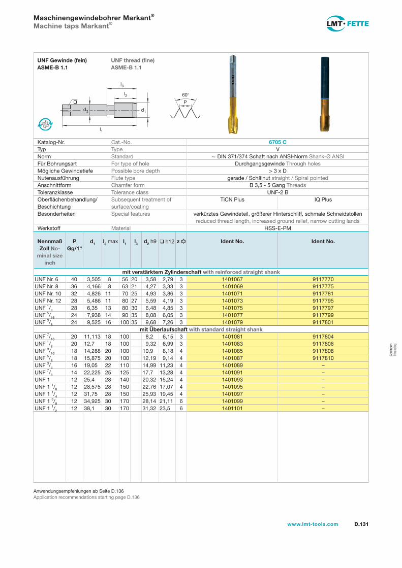
l1
d2
l2
d1
60
P
l3
D.131www.lmt-tools.com
UNF thread (fine) ASME-B 1.1
UNF Gewinde (fein) ASME-B 1.1
Anwendungsempfehlungen ab Seite D.136Application recommendations starting page D.136
Maschinengewindebohrer Markant®
Machine taps Markant®
Katalog-Nr. Cat.-No. 6705 CTyp Type VNorm Standard DIN 371/374 Schaft nach ANSI-Norm Shank-Ø ANSIFür Bohrungsart For type of hole Durchgangsgewinde Through holesMögliche Gewindetiefe Possible bore depth > 3 x DNutenausführung Flute type gerade / Schälnut straight / Spiral pointedAnschnittform Chamfer form B 3,5 - 5 Gang ThreadsToleranzklasse Tolerance class UNF-2 BOberflächenbehandlung/Beschichtung
Subsequent treatment of surface/coating
TiCN Plus IQ Plus
Besonderheiten Special features verkürztes Gewindeteil, größerer Hinterschliff, schmale Schneidstollen reduced thread length, increased ground relief, narrow cutting lands
Werkstoff Material HSS-E-PM
Nennmaß Zoll No-
minal size inch
PGg/1“
d1 l2 max l1 l3 d2 h9 h12 z Ident No. Ident No.
mit verstärktem Zylinderschaft with reinforced straight shankUNF Nr. 6 40 3,505 8 56 20 3,58 2,79 3 1401067 9117770UNF Nr. 8 36 4,166 8 63 21 4,27 3,33 3 1401069 9117775UNF Nr. 10 32 4,826 11 70 25 4,93 3,86 3 1401071 9117781UNF Nr. 12 28 5,486 11 80 27 5,59 4,19 3 1401073 9117795UNF 1/4 28 6,35 13 80 30 6,48 4,85 3 1401075 9117797UNF 5/16 24 7,938 14 90 35 8,08 6,05 3 1401077 9117799UNF 3/8 24 9,525 16 100 35 9,68 7,26 3 1401079 9117801
mit Überlaufschaft with standard straight shankUNF 7/16 20 11,113 18 100 8,2 6,15 3 1401081 9117804UNF 1/2 20 12,7 18 100 9,32 6,99 3 1401083 9117806UNF 9/16 18 14,288 20 100 10,9 8,18 4 1401085 9117808UNF 5/8 18 15,875 20 100 12,19 9,14 4 1401087 9117810UNF 3/4 16 19,05 22 110 14,99 11,23 4 1401089 –UNF 7/8 14 22,225 25 125 17,7 13,28 4 1401091 –UNF 1 12 25,4 28 140 20,32 15,24 4 1401093 –UNF 1 1/8 12 28,575 28 150 22,76 17,07 4 1401095 –UNF 1 1/4 12 31,75 28 150 25,93 19,45 4 1401097 –UNF 1 3/8 12 34,925 30 170 28,14 21,11 6 1401099 –UNF 1 1/2 12 38,1 30 170 31,32 23,5 6 1401101 –
Gew
inde
n Th
read
ing
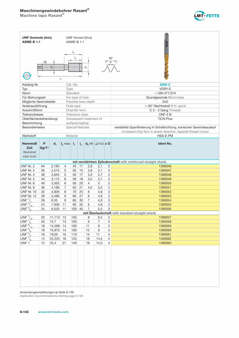
l1
d2
l2
d1
60
P
l3
D.132 www.lmt-tools.com
UNF thread (fine) ASME-B 1.1
UNF Gewinde (fein) ASME-B 1.1
Anwendungsempfehlungen ab Seite D.136Application recommendations starting page D.136
Maschinengewindebohrer Rasant®
Machine taps Rasant®
Katalog-Nr. Cat.-No. 6569 CTyp Type VDRY-SNorm Standard DIN 371/374Für Bohrungsart For type of hole Grundgewinde Blind holesMögliche Gewindetiefe Possible bore depth 3xDNutenausführung Flute type 50° Rechtsdrall R.H. spiralAnschnittform Chamfer form C 2 - 3 Gang ThreadsToleranzklasse Tolerance class UNF-2 BOberflächenbehandlung/Beschichtung
Subsequent treatment of surface/coating
TiCN Plus
Besonderheiten Special features verstärkte Spanförderung in Schaftrichtung, konischer Gewindeauslauf increased chip flow in shank direction, tapered thread runout
Werkstoff Material HSS-E-PM
Nennmaß Zoll
Nominal size inch
PGg/1“
d1 l2 max l1 l3 d2 h9 h12 z Ident No.
mit verstärktem Zylinderschaft with reinforced straight shankUNF Nr. 2 64 2,184 4 45 11 2,8 2,1 3 1390046UNF Nr. 3 56 2,515 5 50 15 2,8 2,1 3 1390047UNF Nr. 4 48 2,845 5 56 17 3,5 2,7 3 1390048UNF Nr. 5 44 3,175 6 56 18 3,5 2,7 3 1390049UNF Nr. 6 40 3,505 6 56 20 4 3 3 1390050UNF Nr. 8 36 4,166 7 63 21 4,5 3,4 3 1390051UNF Nr. 10 32 4,826 8 70 25 6 4,9 3 1390052UNF Nr. 12 28 5,486 9 80 27 6 4,9 3 1390053UNF 1/4 28 6,35 9 80 30 7 4,9 3 1390054UNF 5/16 24 7,938 11 90 35 6 4,9 3 1390055UNF 3/8 24 9,525 11 100 40 7 5,5 3 1390056
mit Überlaufschaft with standard straight shankUNF 7/16 20 11,113 13 100 8 6,2 3 1390057UNF 1/2 20 12,7 13 100 9 7 3 1390058UNF 9/16 18 14,288 14 100 11 9 3 1390059UNF 5/8 18 15,875 14 100 12 9 4 1390060UNF 3/4 16 19,05 16 110 14 11 4 1390061UNF 7/8 14 22,225 18 125 18 14,5 4 1390062UNF 1 12 25,4 21 140 18 14,5 4 1390063
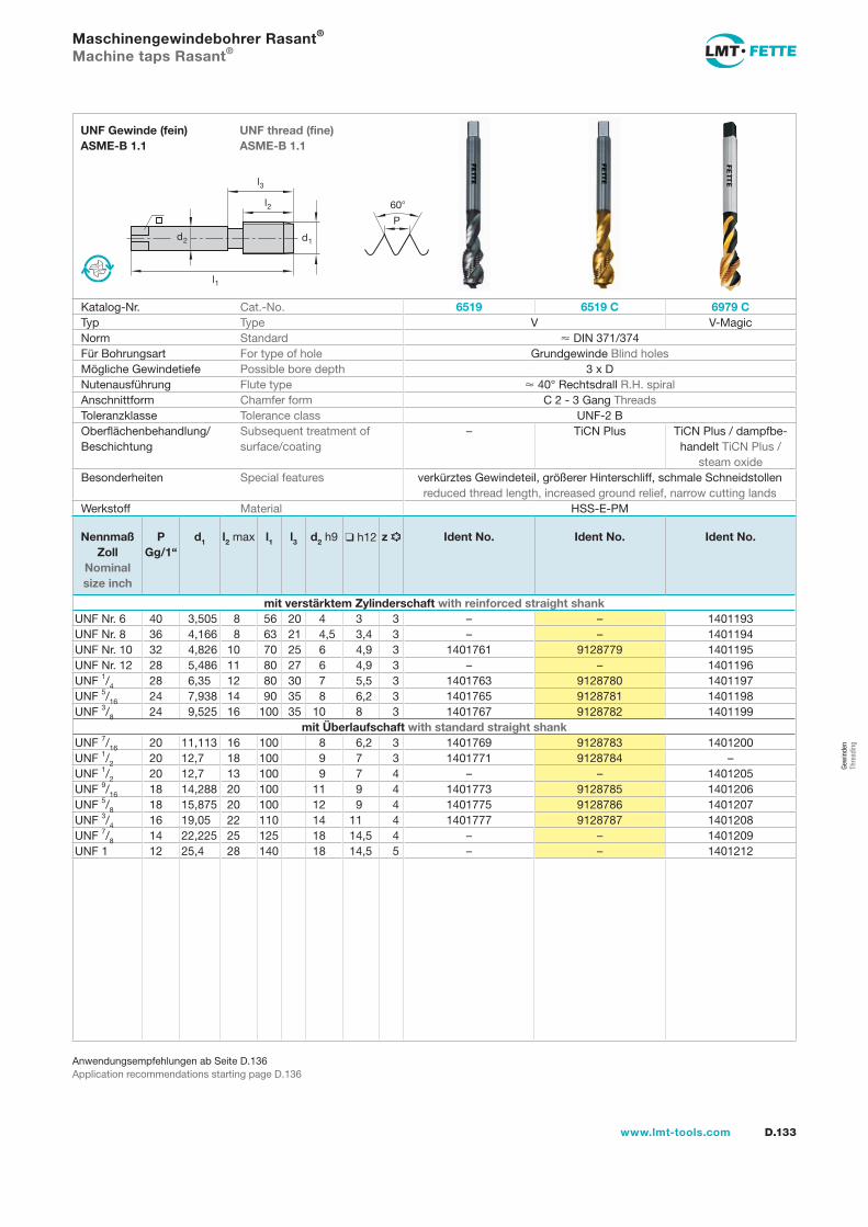
l1
d2
l2
d1
60
P
l3
D.133www.lmt-tools.com
UNF thread (fine) ASME-B 1.1
UNF Gewinde (fein) ASME-B 1.1
Anwendungsempfehlungen ab Seite D.136Application recommendations starting page D.136
Maschinengewindebohrer Rasant®
Machine taps Rasant®
Katalog-Nr. Cat.-No. 6519 6519 C 6979 CTyp Type V V-MagicNorm Standard DIN 371/374Für Bohrungsart For type of hole Grundgewinde Blind holesMögliche Gewindetiefe Possible bore depth 3 x DNutenausführung Flute type 40° Rechtsdrall R.H. spiralAnschnittform Chamfer form C 2 - 3 Gang ThreadsToleranzklasse Tolerance class UNF-2 BOberflächenbehandlung/Beschichtung
Subsequent treatment of surface/coating
– TiCN Plus TiCN Plus / dampfbe-handelt TiCN Plus /
steam oxideBesonderheiten Special features verkürztes Gewindeteil, größerer Hinterschliff, schmale Schneidstollen
reduced thread length, increased ground relief, narrow cutting landsWerkstoff Material HSS-E-PM
Nennmaß Zoll
Nominal size inch
PGg/1“
d1 l2 max l1 l3 d2 h9 h12 z Ident No. Ident No. Ident No.
mit verstärktem Zylinderschaft with reinforced straight shankUNF Nr. 6 40 3,505 8 56 20 4 3 3 – – 1401193UNF Nr. 8 36 4,166 8 63 21 4,5 3,4 3 – – 1401194UNF Nr. 10 32 4,826 10 70 25 6 4,9 3 1401761 9128779 1401195UNF Nr. 12 28 5,486 11 80 27 6 4,9 3 – – 1401196UNF 1/4 28 6,35 12 80 30 7 5,5 3 1401763 9128780 1401197UNF 5/16 24 7,938 14 90 35 8 6,2 3 1401765 9128781 1401198UNF 3/8 24 9,525 16 100 35 10 8 3 1401767 9128782 1401199
mit Überlaufschaft with standard straight shankUNF 7/16 20 11,113 16 100 8 6,2 3 1401769 9128783 1401200UNF 1/2 20 12,7 18 100 9 7 3 1401771 9128784 –UNF 1/2 20 12,7 13 100 9 7 4 – – 1401205UNF 9/16 18 14,288 20 100 11 9 4 1401773 9128785 1401206UNF 5/8 18 15,875 20 100 12 9 4 1401775 9128786 1401207UNF 3/4 16 19,05 22 110 14 11 4 1401777 9128787 1401208UNF 7/8 14 22,225 25 125 18 14,5 4 – – 1401209UNF 1 12 25,4 28 140 18 14,5 5 – – 1401212
Gew
inde
n Th
read
ing
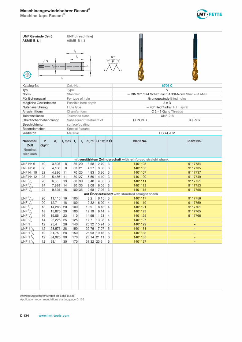
l1
d2
l2
d1
60
P
l3
D.134 www.lmt-tools.com
UNF thread (fine) ASME-B 1.1
UNF Gewinde (fein) ASME-B 1.1
Anwendungsempfehlungen ab Seite D.136Application recommendations starting page D.136
Maschinengewindebohrer Rasant®
Machine taps Rasant®
Katalog-Nr. Cat.-No. 6706 CTyp Type VNorm Standard DIN 371/374 Schaft nach ANSI-Norm Shank-Ø ANSIFür Bohrungsart For type of hole Grundgewinde Blind holesMögliche Gewindetiefe Possible bore depth 3 x DNutenausführung Flute type 40° Rechtsdrall R.H. spiralAnschnittform Chamfer form C 2 - 3 Gang ThreadsToleranzklasse Tolerance class UNF-2 BOberflächenbehandlung/Beschichtung
Subsequent treatment of surface/coating
TiCN Plus IQ Plus
Besonderheiten Special features – –Werkstoff Material HSS-E-PM
Nennmaß Zoll
Nominal size inch
PGg/1“
d1 l2 max l1 l3 d2 h9 h12 z Ident No. Ident No.
mit verstärktem Zylinderschaft with reinforced straight shankUNF Nr. 6 40 3,505 8 56 20 3,58 2,79 3 1401103 9117734UNF Nr. 8 36 4,166 8 63 21 4,27 3,33 3 1401105 9117735UNF Nr. 10 32 4,826 11 70 25 4,93 3,86 3 1401107 9117737UNF Nr. 12 28 5,486 11 80 27 5,59 4,19 3 1401109 9117749UNF 1/4 28 6,35 13 80 30 6,48 4,85 3 1401111 9117751UNF 5/16 24 7,938 14 90 35 8,08 6,05 3 1401113 9117753UNF 3/8 24 9,525 16 100 35 9,68 7,26 3 1401115 9117755
mit Überlaufschaft with standard straight shankUNF 7/16 20 11,113 18 100 8,2 6,15 3 1401117 9117758UNF 1/2 20 12,7 18 100 9,32 6,99 4 1401119 9117759UNF 9/16 18 14,288 20 100 10,9 8,18 4 1401121 9117761UNF 5/8 18 15,875 20 100 12,19 9,14 4 1401123 9117765UNF 3/4 16 19,05 22 110 14,99 11,23 4 1401125 9117766UNF 7/8 14 22,225 25 125 17,7 13,28 4 1401127 –UNF 1 12 25,4 28 140 20,32 15,24 5 1401129 –UNF 1 1/8 12 28,575 28 150 22,76 17,07 5 1401131 –UNF 1 1/4 12 31,75 28 150 25,93 19,45 5 1401133 –UNF 1 3/8 12 34,925 30 170 28,14 21,11 6 1401135 –UNF 1 1/2 12 38,1 30 170 31,32 23,5 6 1401137 –
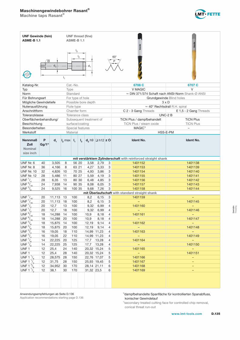
l1
d2
l2
d1
60
P
l3
D.135www.lmt-tools.com
UNF thread (fine) ASME-B 1.1
UNF Gewinde (fein) ASME-B 1.1
Anwendungsempfehlungen ab Seite D.136Application recommendations starting page D.136
Maschinengewindebohrer Rasant®
Machine taps Rasant®
Katalog-Nr. Cat.-No. 6708 C 6707 CTyp Type V MAGIC VNorm Standard DIN 371/374 Schaft nach ANSI-Norm Shank-Ø ANSIFür Bohrungsart For type of hole Grundgewinde Blind holesMögliche Gewindetiefe Possible bore depth 3 x DNutenausführung Flute type 40° Rechtsdrall R.H. spiralAnschnittform Chamfer form C 2 - 3 Gang Threads E 1,5 - 2 Gang ThreadsToleranzklasse Tolerance class UNC-2 BOberflächenbehandlung/Beschichtung
Subsequent treatment of surface/coating
TiCN Plus / dampfbehandelt TiCN Plus TiCN Plus / steam oxide TiCN Plus
Besonderheiten Special features MAGIC1) –Werkstoff Material HSS-E-PM
1)dampfbehandelte Spanfläche für kontrollierten Spanabfluss, konischer Gewindelauf 1)secondary treated cutting face for controlled chip removal, conical threat run-out
Nennmaß Zoll
Nominal size inch
PGg/1“
d1 l2 max l1 l3 d2 h9 h12 z Ident No. Ident No.
mit verstärktem Zylinderschaft with reinforced straight shankUNF Nr. 6 40 3,505 8 56 20 3,58 2,79 3 1401152 1401138UNF Nr. 8 36 4,166 8 63 21 4,27 3,33 3 1401153 1401139UNF Nr. 10 32 4,826 10 70 25 4,93 3,86 3 1401154 1401140UNF Nr. 12 28 5,486 11 80 27 5,59 4,19 3 1401155 1401141UNF 1/4 28 6,35 13 80 30 6,48 4,85 3 1401156 1401142UNF 5/16 24 7,938 14 90 35 8,08 6,05 3 1401157 1401143UNF 3/8 24 9,525 16 100 35 9,68 7,26 3 1401158 1401144
mit Überlaufschaft with standard straight shankUNF 7/16 20 11,113 13 100 8,2 6,15 3 1401159 –UNF 7/16 20 11,113 18 100 8,2 6,15 3 – 1401145UNF 1/2 20 12,7 13 100 9,32 6,99 4 1401160 –UNF 1/2 20 12,7 18 100 9,32 6,99 4 – 1401146UNF 9/16 18 14,288 14 100 10,9 8,18 4 1401161 –UNF 9/16 18 14,288 20 100 10,9 8,18 4 – 1401147UNF 5/8 18 15,875 14 100 12,19 9,14 4 1401162 –UNF 5/8 18 15,875 20 100 12,19 9,14 4 – 1401148UNF 3/4 16 19,05 18 110 14,99 11,23 4 1401163 –UNF 3/4 16 19,05 22 110 14,99 11,23 4 – 1401149UNF 7/8 14 22,225 20 125 17,7 13,28 4 1401164 –UNF 7/8 14 22,225 25 125 17,7 13,28 4 – 1401150UNF 1 12 25,4 24 140 20,32 15,24 5 1401165 –UNF 1 12 25,4 28 140 20,32 15,24 5 – 1401151UNF 1 1/8 12 28,575 28 150 22,76 17,07 5 1401166 –UNF 1 1/4 12 31,75 28 150 25,93 19,45 5 1401167 –UNF 1 3/8 12 34,952 30 170 28,14 21,11 6 1401168 –UNF 1 1/2 12 38,1 30 170 31,32 23,5 6 1401169 –
Gew
inde
n Th
read
ing
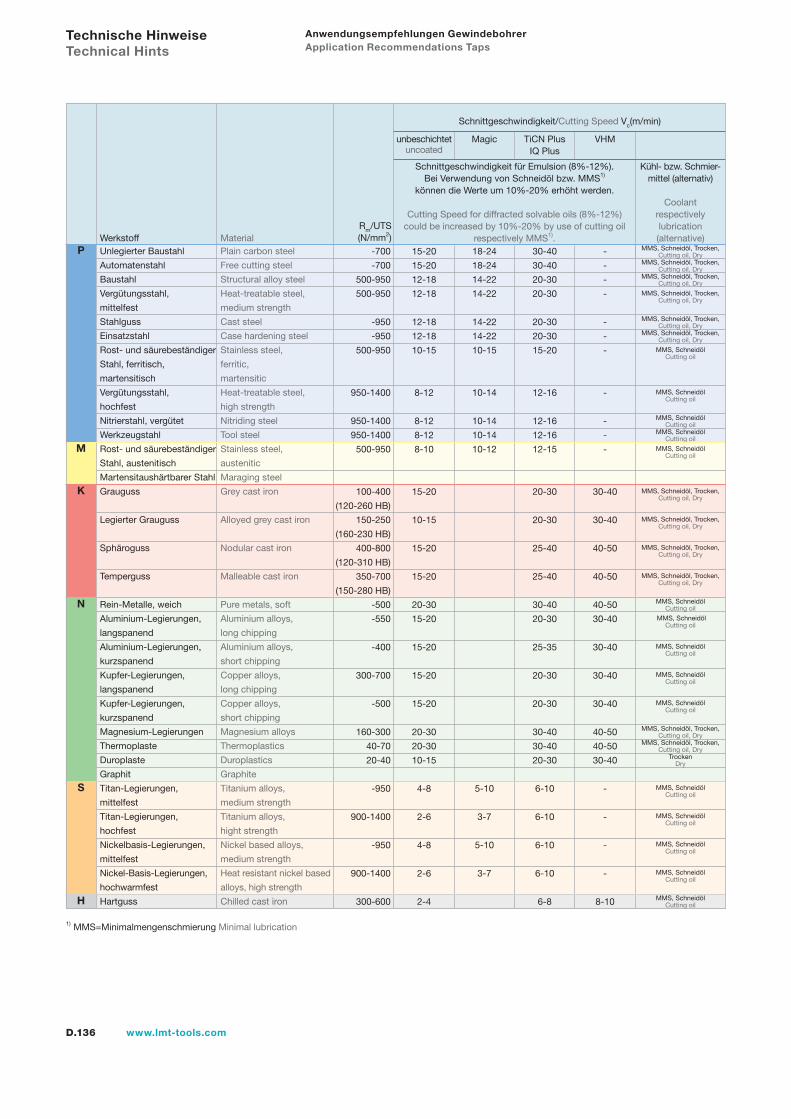
D.136 www.lmt-tools.com
18-24
18-24
14-22
14-22
14-22
14-22
10-15
10-14
10-14
10-14
10-12
5-10
3-7
5-10
3-7
30-40
30-40
20-30
20-30
20-30
20-30
15-20
12-16
12-16
12-16
12-15
20-30
20-30
25-40
25-40
30-40
20-30
25-35
20-30
20-30
30-40
30-40
20-30
6-10
6-10
6-10
6-10
6-8
-
-
-
-
-
-
-
-
-
-
-
30-40
30-40
40-50
40-50
40-50
30-40
30-40
30-40
30-40
40-50
40-50
30-40
-
-
-
-
8-10
Anwendungsempfehlungen Gewindebohrer Application Recommendations Taps
1) MMS=Minimalmengenschmierung Minimal lubrication
Rm/UTS(N/mm2)
Schnittgeschwindigkeit/Cutting Speed Vc(m/min)
unbeschichtetuncoated
Magic
Schnittgeschwindigkeit für Emulsion (8%-12%). Bei Verwendung von Schneidöl bzw. MMS1)
können die Werte um 10%-20% erhöht werden.
Cutting Speed for diffracted solvable oils (8%-12%) could be increased by 10%-20% by use of cutting oil
respectively MMS1).
Kühl- bzw. Schmier- mittel (alternativ)
Coolant respectively lubrication (alternative)
TiCN PlusIQ Plus
VHM
Unlegierter Baustahl Plain carbon steel
Automatenstahl Free cutting steel
Baustahl Structural alloy steel
Vergütungsstahl, Heat-treatable steel,
mittelfest medium strength
Stahlguss Cast steel
Einsatzstahl Case hardening steel
Rost- und säurebeständiger Stainless steel,
Stahl, ferritisch, ferritic,
martensitisch martensitic
Vergütungsstahl, Heat-treatable steel,
hochfest high strength
Nitrierstahl, vergütet Nitriding steel
Werkzeugstahl Tool steel
Rost- und säurebeständiger Stainless steel,
Stahl, austenitisch austenitic
Martensitaushärtbarer Stahl Maraging steel
Grauguss Grey cast iron
Legierter Grauguss Alloyed grey cast iron
Sphäroguss Nodular cast iron
Temperguss Malleable cast iron
Rein-Metalle, weich Pure metals, soft
Aluminium-Legierungen, Aluminium alloys,
langspanend long chipping
Aluminium-Legierungen, Aluminium alloys,
kurzspanend short chipping
Kupfer-Legierungen, Copper alloys,
langspanend long chipping
Kupfer-Legierungen, Copper alloys,
kurzspanend short chipping
Magnesium-Legierungen Magnesium alloys
Thermoplaste Thermoplastics
Duroplaste Duroplastics
Graphit Graphite
Titan-Legierungen, Titanium alloys,
mittelfest medium strength
Titan-Legierungen, Titanium alloys,
hochfest hight strength
Nickelbasis-Legierungen, Nickel based alloys,
mittelfest medium strength
Nickel-Basis-Legierungen, Heat resistant nickel based
hochwarmfest alloys, high strength
Hartguss Chilled cast iron
Werkstoff Material -700
-700
500-950
500-950
-950
-950
500-950
950-1400
950-1400
950-1400
500-950
100-400
(120-260 HB)
150-250
(160-230 HB)
400-800
(120-310 HB)
350-700
(150-280 HB)
-500
-550
-400
300-700
-500
160-300
40-70
20-40
-950
900-1400
-950
900-1400
300-600
15-20
15-20
12-18
12-18
12-18
12-18
10-15
8-12
8-12
8-12
8-10
15-20
10-15
15-20
15-20
20-30
15-20
15-20
15-20
15-20
20-30
20-30
10-15
4-8
2-6
4-8
2-6
2-4
MMS, Schneidöl, Trocken, Cutting oil, Dry
MMS, Schneidöl, Trocken, Cutting oil, Dry
MMS, Schneidöl, Trocken, Cutting oil, Dry
MMS, Schneidöl, Trocken, Cutting oil, Dry
MMS, Schneidöl, Trocken, Cutting oil, Dry
MMS, Schneidöl, Trocken, Cutting oil, Dry
MMS, Schneidöl Cutting oil
MMS, Schneidöl Cutting oil
MMS, Schneidöl Cutting oil
MMS, Schneidöl Cutting oil
MMS, Schneidöl Cutting oil
MMS, Schneidöl, Trocken, Cutting oil, Dry
MMS, Schneidöl, Trocken, Cutting oil, Dry
MMS, Schneidöl, Trocken, Cutting oil, Dry
MMS, Schneidöl, Trocken, Cutting oil, Dry
MMS, Schneidöl Cutting oil
MMS, Schneidöl Cutting oil
MMS, Schneidöl Cutting oil
MMS, Schneidöl Cutting oil
MMS, Schneidöl Cutting oil
MMS, Schneidöl, Trocken, Cutting oil, Dry
MMS, Schneidöl, Trocken, Cutting oil, Dry
Trocken Dry
MMS, Schneidöl Cutting oil
MMS, Schneidöl Cutting oil
MMS, Schneidöl Cutting oil
MMS, Schneidöl Cutting oil
MMS, Schneidöl Cutting oil
Technische Hinweise Technical Hints
P
M
K
N
S
H

D.137www.lmt-tools.com
NotizenNotes
Gew
inde
n Th
read
ing
D.138 www.lmt-tools.com
Gewindebohrer G, UNJF/MJ, NPT/NPTF, BSW, RPTaps G, UNJF/MJ, NPT/NPTF, BSW, RP
D.139www.lmt-tools.com
Gewindebohrer G, UNJF/MJ, NPT/NPTF, BSW, RP Taps G, UNJF/MJ, NPT/NPTF, BSW, RP
D.140 Auswahlübersicht Gewindebohrer Selection table taps
D.144 Typenbeschreibungen Type descriptions
Typen Type
Vdry-S D.154N D.148, D.149, D.150, D.153, D.156, D.157, D.159, D.160, D.162
N-R 15 D.162V D.152, D.154, D.160VR-15 D.154
V-Magic D.154 VDry-S D.154 V-AZ D.158
H D.156 G D.151, D.162 D.148 G - Whitworth Rohrgewinde (BSP) G - Whitworth pipe threads (BSP)
D.156 Metrisch MJ/UNF Gewinde Metric MJ/UNFJ thread
D.157 NPT - Amerikanisches kegeliges Rohrgewinde NPTF - American taper pipe thread
D.159 BSW - Whitworth Gewinde BSW - Whitworth threads
D.162 RP - Gewinde nach DIN 2999 RP - Threads to DIN 2999
D.163 Anwendungsempfehlungen Application recommendations
Gew
inde
n Th
read
ing
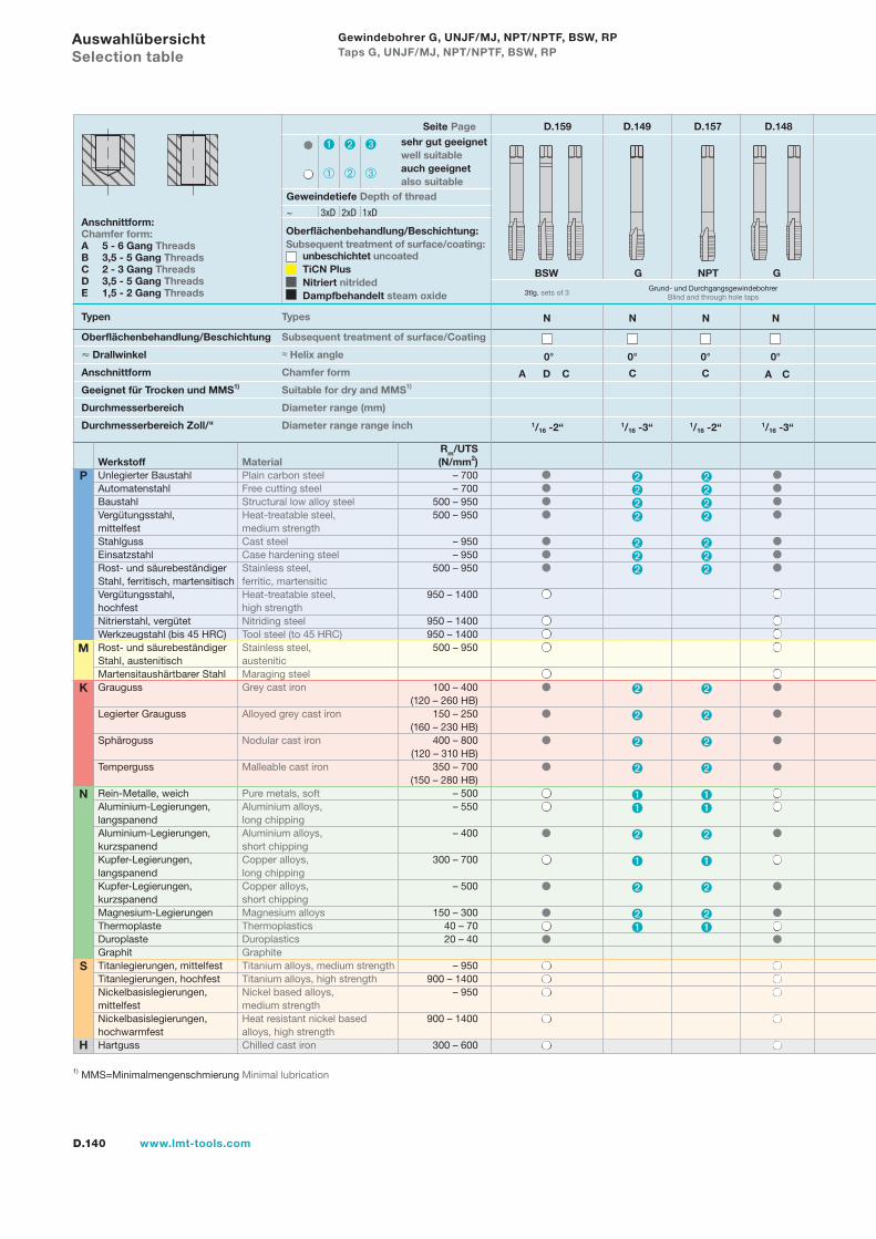
D.140 www.lmt-tools.com
Auswahlübersicht Selection table
Typen Types
Anschnittform:Chamfer form:A 5 - 6 Gang ThreadsB 3,5 - 5 Gang ThreadsC 2 - 3 Gang ThreadsD 3,5 - 5 Gang ThreadsE 1,5 - 2 Gang Threads
Oberflächenbehandlung/Beschichtung:Subsequent treatment of surface/coating:
unbeschichtet uncoatedTiCN PlusNitriert nitridedDampfbehandelt steam oxide
0°
N
A D C
1/16 -2“
Seite Page D.159 D.149 D.157 D.148
1) MMS=Minimalmengenschmierung Minimal lubrication
N
S
H
P
K
M
Rm/UTSWerkstoff Material (N/mm2)Unlegierter Baustahl Plain carbon steel – 700Automatenstahl Free cutting steel – 700Baustahl Structural low alloy steel 500 – 950Vergütungsstahl, Heat-treatable steel, 500 – 950mittelfest medium strengthStahlguss Cast steel – 950Einsatzstahl Case hardening steel – 950Rost- und säurebeständiger Stainless steel, 500 – 950Stahl, ferritisch, martensitisch ferritic, martensiticVergütungsstahl, Heat-treatable steel, 950 – 1400hochfest high strengthNitrierstahl, vergütet Nitriding steel 950 – 1400Werkzeugstahl (bis 45 HRC) Tool steel (to 45 HRC) 950 – 1400Rost- und säurebeständiger Stainless steel, 500 – 950Stahl, austenitisch austeniticMartensitaushärtbarer Stahl Maraging steelGrauguss Grey cast iron 100 – 400 (120 – 260 HB)Legierter Grauguss Alloyed grey cast iron 150 – 250 (160 – 230 HB)Sphäroguss Nodular cast iron 400 – 800 (120 – 310 HB)Temperguss Malleable cast iron 350 – 700 (150 – 280 HB)Rein-Metalle, weich Pure metals, soft – 500Aluminium-Legierungen, Aluminium alloys, – 550langspanend long chippingAluminium-Legierungen, Aluminium alloys, – 400kurzspanend short chippingKupfer-Legierungen, Copper alloys, 300 – 700langspanend long chippingKupfer-Legierungen, Copper alloys, – 500kurzspanend short chippingMagnesium-Legierungen Magnesium alloys 150 – 300Thermoplaste Thermoplastics 40 – 70Duroplaste Duroplastics 20 – 40Graphit GraphiteTitanlegierungen, mittelfest Titanium alloys, medium strength – 950Titanlegierungen, hochfest Titanium alloys, high strength 900 – 1400Nickelbasislegierungen, Nickel based alloys, – 950mittelfest medium strengthNickelbasislegierungen, Heat resistant nickel based 900 – 1400hochwarmfest alloys, high strengthHartguss Chilled cast iron 300 – 600
sehr gut geeignetwell suitableauch geeignetalso suitable
Geweindetiefe Depth of thread
~ 3xD 2xD 1xD
0°
N
C
1/16 -3“
Grund- und DurchgangsgewindebohrerBlind and through hole taps
G
Oberflächenbehandlung/Beschichtung Subsequent treatment of surface/Coating
Drallwinkel ≈ Helix angle
Anschnittform Chamfer form
Geeignet für Trocken und MMS1) Suitable for dry and MMS1)
Durchmesserbereich Diameter range (mm)
Durchmesserbereich Zoll/" Diameter range range inch
0°
N
C
1/16 -2“
NPTBSW
3tlg. sets of 3
0°
N
A C
1/16 -3“
G
Gewindebohrer G, UNJF/MJ, NPT/NPTF, BSW, RP Taps G, UNJF/MJ, NPT/NPTF, BSW, RP
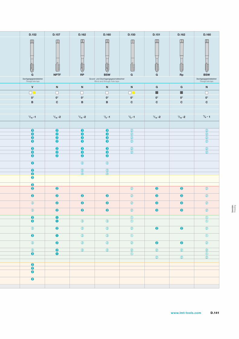
D.141www.lmt-tools.com
Gew
inde
n Th
read
ing
D.152 D.157 D.162 D.160 D.150 D.151 D.162 D.160
0°
N
C
1/16 -2
NPTF
0°
V
B
1/16 -1
G
0°
N
B
1/16 -2
RP
0°
N
B
1/8 -1
BSW
0°
N
C
1/8 -1
G
0°
G
C
1/16 -2
G
0°
G
C
1/16 -2
Rp
0°
N
C
1/8 - 1
BSWGrund- und Durchgangsgewindebohrer
Blind and through hole tapsDurchgangsgewindebohrer
Through hole tapsDurchgangsgewindebohrer
Through hole taps
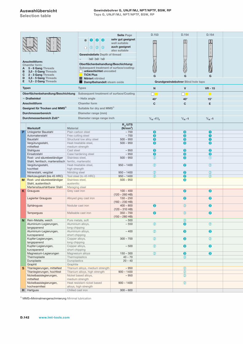
D.142 www.lmt-tools.com
Auswahlübersicht Selection table
Typen Types
Anschnittform:Chamfer form:A 5 - 6 Gang ThreadsB 3,5 - 5 Gang ThreadsC 2 - 3 Gang ThreadsD 3,5 - 5 Gang ThreadsE 1,5 - 2 Gang Threads
Oberflächenbehandlung/Beschichtung:Subsequent treatment of surface/coating:
unbeschichtet uncoatedTiCN PlusNitriert nitridedDampfbehandelt steam oxide
Seite Page D.153 D.154 D.154
1) MMS=Minimalmengenschmierung Minimal lubrication
N
S
H
P
K
M
Rm/UTSWerkstoff Material (N/mm2)Unlegierter Baustahl Plain carbon steel – 700Automatenstahl Free cutting steel – 700Baustahl Structural low alloy steel 500 – 950Vergütungsstahl, Heat-treatable steel, 500 – 950mittelfest medium strengthStahlguss Cast steel – 950Einsatzstahl Case hardening steel – 950Rost- und säurebeständiger Stainless steel, 500 – 950Stahl, ferritisch, martensitisch ferritic, martensiticVergütungsstahl, Heat-treatable steel, 950 – 1400hochfest high strengthNitrierstahl, vergütet Nitriding steel 950 – 1400Werkzeugstahl (bis 45 HRC) Tool steel (to 45 HRC) 950 – 1400Rost- und säurebeständiger Stainless steel, 500 – 950Stahl, austenitisch austeniticMartensitaushärtbarer Stahl Maraging steelGrauguss Grey cast iron 100 – 400 (120 – 260 HB)Legierter Grauguss Alloyed grey cast iron 150 – 250 (160 – 230 HB)Sphäroguss Nodular cast iron 400 – 800 (120 – 310 HB)Temperguss Malleable cast iron 350 – 700 (150 – 280 HB)Rein-Metalle, weich Pure metals, soft – 500Aluminium-Legierungen, Aluminium alloys, – 550langspanend long chippingAluminium-Legierungen, Aluminium alloys, – 400kurzspanend short chippingKupfer-Legierungen, Copper alloys, 300 – 700langspanend long chippingKupfer-Legierungen, Copper alloys, – 500kurzspanend short chippingMagnesium-Legierungen Magnesium alloys 150 – 300Thermoplaste Thermoplastics 40 – 70Duroplaste Duroplastics 20 – 40Graphit GraphiteTitanlegierungen, mittelfest Titanium alloys, medium strength – 950Titanlegierungen, hochfest Titanium alloys, high strength 900 – 1400Nickelbasislegierungen, Nickel based alloys, – 950mittelfest medium strengthNickelbasislegierungen, Heat resistant nickel based 900 – 1400hochwarmfest alloys, high strengthHartguss Chilled cast iron 300 – 600
sehr gut geeignetwell suitableauch geeignetalso suitable
Geweindetiefe Depth of thread
~ 3xD 2xD 1xD
Oberflächenbehandlung/Beschichtung Subsequent treatment of surface/Coating
Drallwinkel ≈ Helix angle
Anschnittform Chamfer form
Geeignet für Trocken und MMS1) Suitable for dry and MMS1)
Durchmesserbereich Diameter range (mm)
Durchmesserbereich Zoll/" Diameter range range inch
40°
N
C
1/16 -11/2
40°
V
C
1/16 -1
15°
VR - 15
E
1/16 -1
GGG
Grundgewindebohrer Blind hole taps
Gewindebohrer G, UNJF/MJ, NPT/NPTF, BSW, RP Taps G, UNJF/MJ, NPT/NPTF, BSW, RP
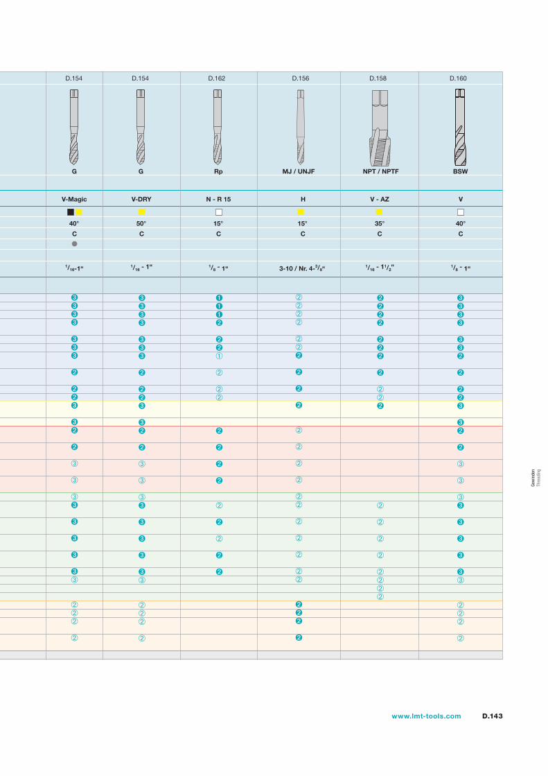
D.143www.lmt-tools.com
Gew
inde
n Th
read
ing
D.154 D.154 D.162 D.156 D.158 D.160
40°
V-Magic
C
1/16-1“
G
50°
V-DRY
C
1/16 - 1“
15°
N - R 15
C
1/8 - 1“
Rp
H V - AZ
15° 35°
C C
1/16 - 11/2“
G MJ / UNJF NPT / NPTF
3-10 / Nr. 4-3/8“
BSW
V
40°
C
1/8 - 1“
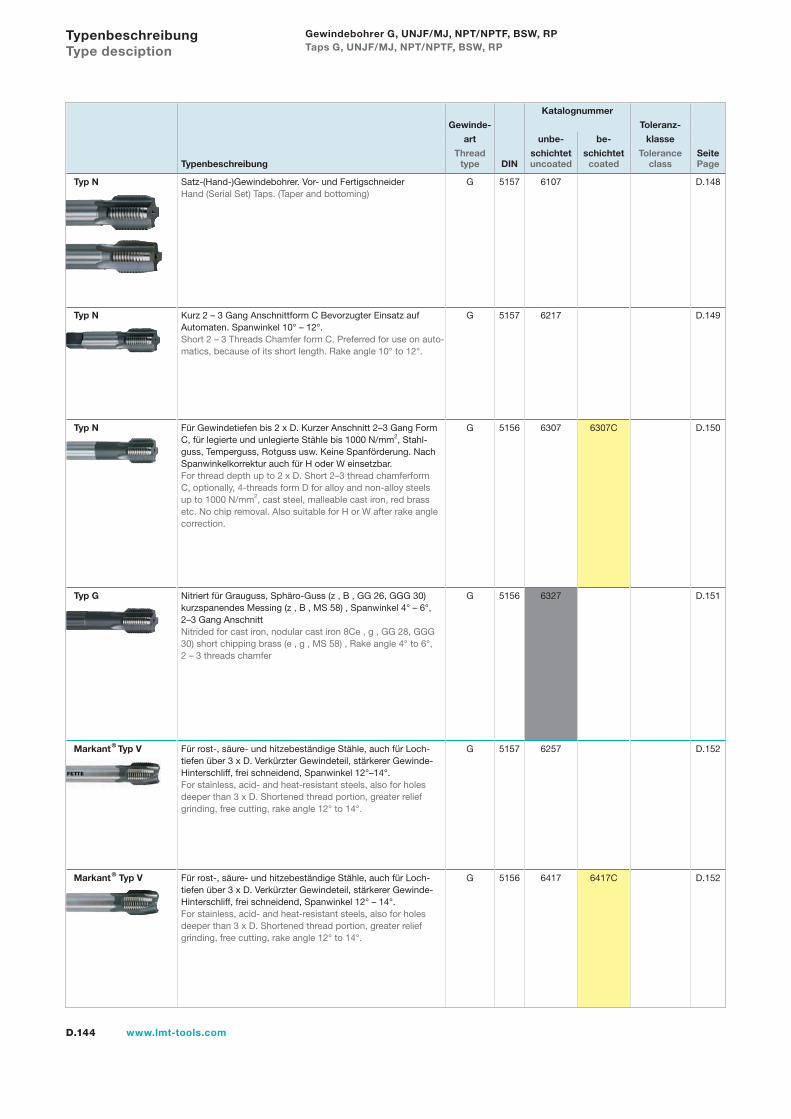
D.144 www.lmt-tools.com
Typenbeschreibung Type desciption
Katalognummer
Gewinde- Toleranz-
art unbe- be- klasse
Thread schichtet schichtet Tolerance SeiteTypenbeschreibung type DIN uncoated coated class Page
Typ N Satz-(Hand-)Gewindebohrer. Vor- und FertigschneiderHand (Serial Set) Taps. (Taper and bottoming)
G 5157 6107 D.148
Typ N Kurz 2 – 3 Gang Anschnittform C Bevorzugter Einsatz auf Automaten. Spanwinkel 10° – 12°.Short 2 – 3 Threads Chamfer form C. Preferred for use on auto-matics, because of its short length. Rake angle 10° to 12°.
G 5157 6217 D.149
Typ N Für Gewindetiefen bis 2 x D. Kurzer Anschnitt 2–3 Gang Form C, für legierte und unlegierte Stähle bis 1000 N/mm2, Stahl-guss, Temperguss, Rotguss usw. Keine Spanförderung. Nach Spanwinkelkorrektur auch für H oder W einsetzbar.For thread depth up to 2 x D. Short 2–3 thread chamferform C, optionally, 4-threads form D for alloy and non-alloy steels up to 1000 N/mm2, cast steel, malleable cast iron, red brass etc. No chip removal. Also suitable for H or W after rake angle correction.
G 5156 6307 6307C D.150
Typ G Nitriert für Grauguss, Sphäro-Guss (z , B , GG 26, GGG 30) kurzspanendes Messing (z , B , MS 58) , Spanwinkel 4° – 6°, 2–3 Gang AnschnittNitrided for cast iron, nodular cast iron 8Ce , g , GG 28, GGG 30) short chipping brass (e , g , MS 58) , Rake angle 4° to 6°, 2 – 3 threads chamfer
G 5156 6327 D.151
Markant® Typ V Für rost-, säure- und hitzebeständige Stähle, auch für Loch-tiefen über 3 x D. Verkürzter Gewindeteil, stärkerer Gewinde-Hinterschliff, frei schneidend, Spanwinkel 12°–14°.For stainless, acid- and heat-resistant steels, also for holes deeper than 3 x D. Shortened thread portion, greater relief grinding, free cutting, rake angle 12° to 14°.
G 5157 6257 D.152
Markant® Typ V Für rost-, säure- und hitzebeständige Stähle, auch für Loch-tiefen über 3 x D. Verkürzter Gewindeteil, stärkerer Gewinde-Hinterschliff, frei schneidend, Spanwinkel 12° – 14°.For stainless, acid- and heat-resistant steels, also for holes deeper than 3 x D. Shortened thread portion, greater relief grinding, free cutting, rake angle 12° to 14°.
G 5156 6417 6417C D.152
Gewindebohrer G, UNJF/MJ, NPT/NPTF, BSW, RP Taps G, UNJF/MJ, NPT/NPTF, BSW, RP
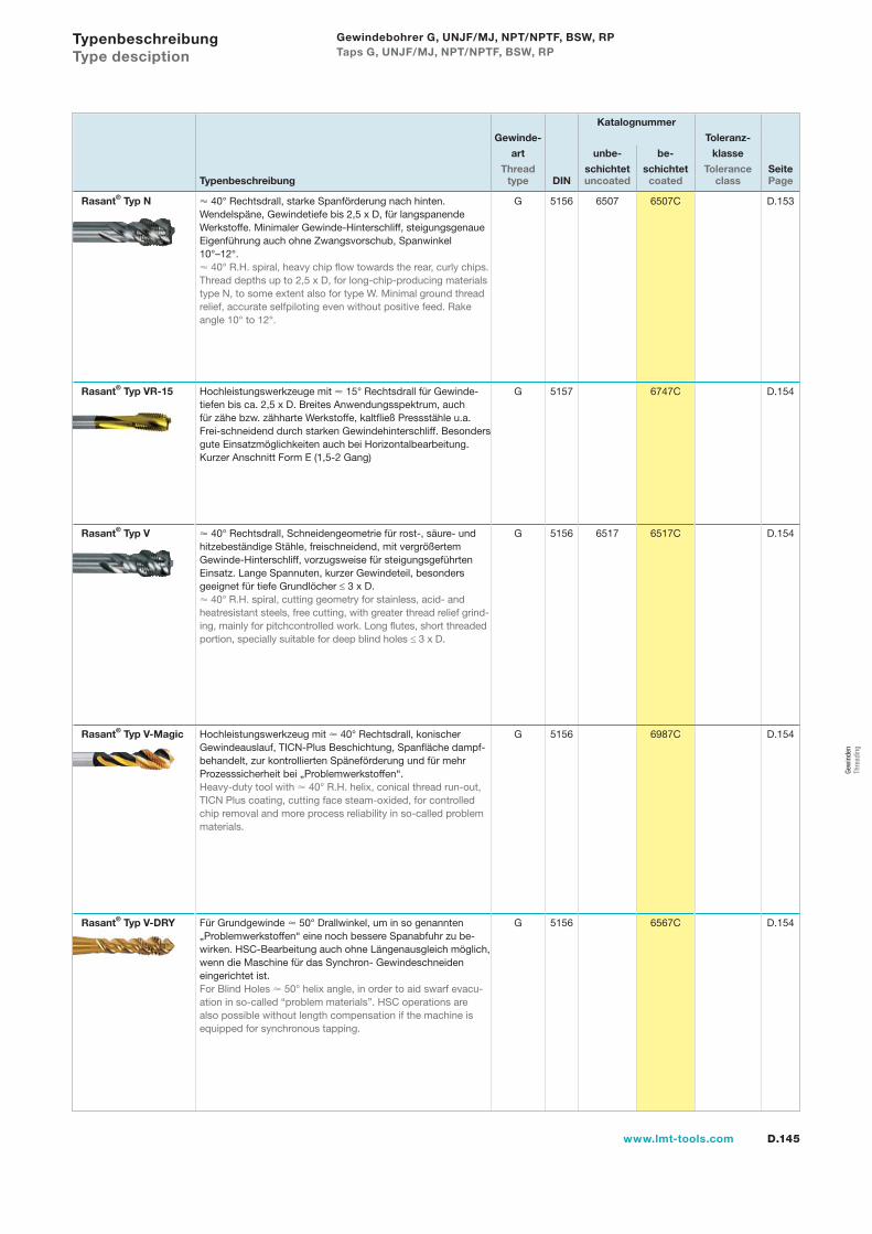
D.145www.lmt-tools.com
Katalognummer
Gewinde- Toleranz-
art unbe- be- klasse
Thread schichtet schichtet Tolerance SeiteTypenbeschreibung type DIN uncoated coated class Page
Rasant® Typ N 40° Rechtsdrall, starke Spanförderung nach hinten. Wendelspäne, Gewindetiefe bis 2,5 x D, für langspanende Werkstoffe. Minimaler Gewinde-Hinterschliff, steigungsgenaue Eigenführung auch ohne Zwangsvorschub, Spanwinkel 10°–12°.
40° R.H. spiral, heavy chip flow towards the rear, curly chips. Thread depths up to 2,5 x D, for long-chip-producing materials type N, to some extent also for type W. Minimal ground thread relief, accurate selfpiloting even without positive feed. Rake angle 10° to 12°.
G 5156 6507 6507C D.153
Rasant® Typ VR-15 Hochleistungswerkzeuge mit 15° Rechtsdrall für Gewinde-tiefen bis ca. 2,5 x D. Breites Anwendungsspektrum, auch für zähe bzw. zähharte Werkstoffe, kaltfließ Pressstähle u.a. Frei-schneidend durch starken Gewindehinterschliff. Besonders gute Einsatzmöglichkeiten auch bei Horizontalbearbeitung.Kurzer Anschnitt Form E (1,5-2 Gang)
G 5157 6747C D.154
Rasant® Typ V 40° Rechtsdrall, Schneidengeometrie für rost-, säure- und hitzebeständige Stähle, freischneidend, mit vergrößertem Gewinde-Hinterschliff, vorzugsweise für steigungsgeführten Einsatz. Lange Spannuten, kurzer Gewindeteil, besonders geeignet für tiefe Grundlöcher ≤ 3 x D.
40° R.H. spiral, cutting geometry for stainless, acid- and heatresistant steels, free cutting, with greater thread relief grind-ing, mainly for pitchcontrolled work. Long flutes, short threaded portion, specially suitable for deep blind holes ≤ 3 x D.
G 5156 6517 6517C D.154
Rasant® Typ V-Magic Hochleistungswerkzeug mit 40° Rechtsdrall, konischerGewindeauslauf, TICN-Plus Beschichtung, Spanfläche dampf-behandelt, zur kontrollierten Späneförderung und für mehr Prozesssicherheit bei „Problemwerkstoffen“.Heavy-duty tool with 40° R.H. helix, conical thread run-out, TICN Plus coating, cutting face steam-oxided, for controlled chip removal and more process reliability in so-called problem materials.
G 5156 6987C D.154
Rasant® Typ V-DRY Für Grundgewinde 50° Drallwinkel, um in so genannten „Problemwerkstoffen“ eine noch bessere Spanabfuhr zu be-wirken. HSC-Bearbeitung auch ohne Längenausgleich möglich, wenn die Maschine für das Synchron- Gewindeschneiden eingerichtet ist.For Blind Holes 50° helix angle, in order to aid swarf evacu-ation in so-called “problem materials”. HSC operations are also possible without length compensation if the machine is equipped for synchronous tapping.
G 5156 6567C D.154
Typenbeschreibung Type desciption
Gewindebohrer G, UNJF/MJ, NPT/NPTF, BSW, RP Taps G, UNJF/MJ, NPT/NPTF, BSW, RP
Gew
inde
n Th
read
ing
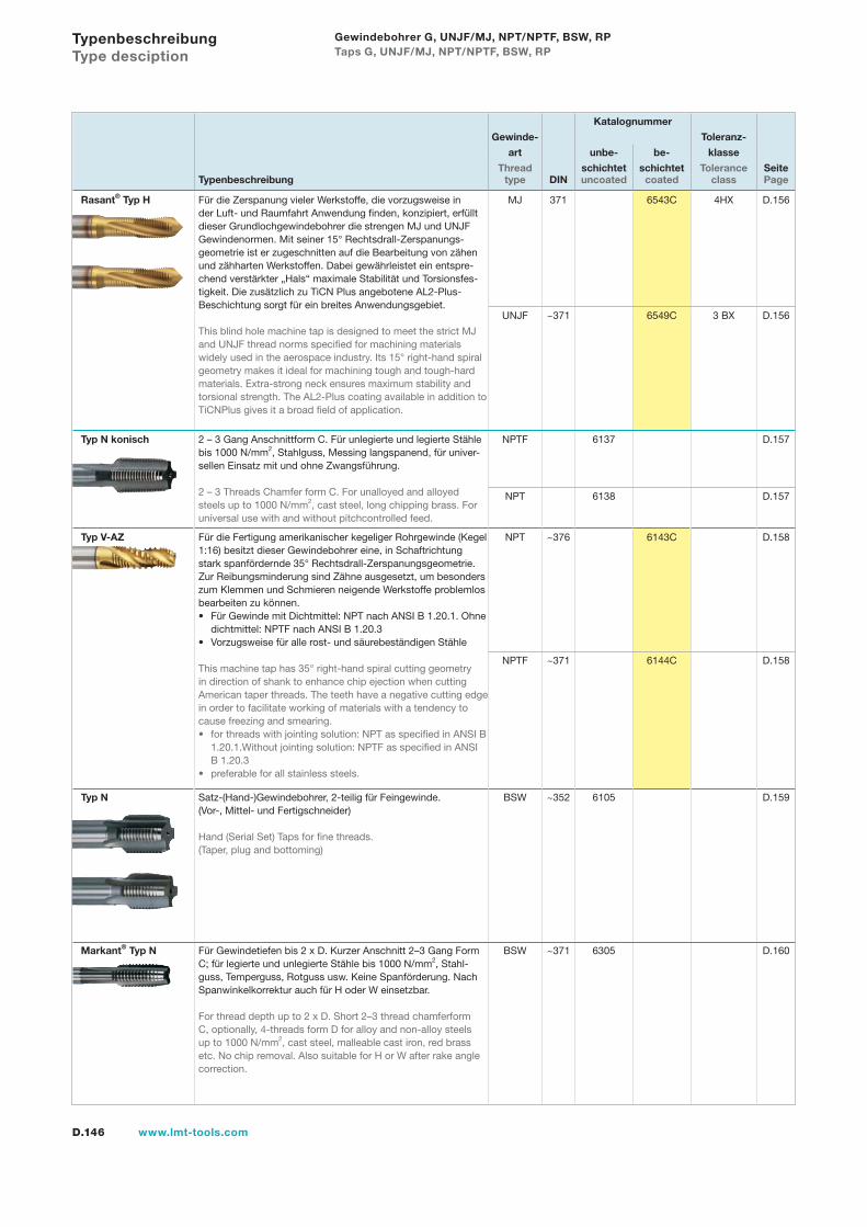
D.146 www.lmt-tools.com
Katalognummer
Gewinde- Toleranz-
art unbe- be- klasse
Thread schichtet schichtet Tolerance SeiteTypenbeschreibung type DIN uncoated coated class Page
Rasant® Typ H Für die Zerspanung vieler Werkstoffe, die vorzugsweise in der Luft- und Raumfahrt Anwendung finden, konzipiert, erfüllt dieser Grundlochgewindebohrer die strengen MJ und UNJF Gewindenormen. Mit seiner 15° Rechtsdrall-Zerspanungs-geometrie ist er zugeschnitten auf die Bearbeitung von zähen und zähharten Werkstoffen. Dabei gewährleistet ein entspre-chend verstärkter „Hals“ maximale Stabilität und Torsionsfes-tigkeit. Die zusätzlich zu TiCN Plus angebotene AL2-Plus- Beschichtung sorgt für ein breites Anwendungsgebiet.
This blind hole machine tap is designed to meet the strict MJ and UNJF thread norms specified for machining materials widely used in the aerospace industry. Its 15° right-hand spiral geometry makes it ideal for machining tough and tough-hard materials. Extra-strong neck ensures maximum stability and torsional strength. The AL2-Plus coating available in addition to TiCNPlus gives it a broad field of application.
MJ 371 6543C 4HX D.156
UNJF ~371 6549C 3 BX D.156
Typ N konisch 2 – 3 Gang Anschnittform C. Für unlegierte und legierte Stählebis 1000 N/mm2, Stahlguss, Messing langspanend, für univer-sellen Einsatz mit und ohne Zwangsführung.
2 – 3 Threads Chamfer form C. For unalloyed and alloyed steels up to 1000 N/mm2, cast steel, long chipping brass. For universal use with and without pitchcontrolled feed.
NPTF 6137 D.157
NPT 6138 D.157
Typ V-AZ Für die Fertigung amerikanischer kegeliger Rohrgewinde (Kegel1:16) besitzt dieser Gewindebohrer eine, in Schaftrichtung stark spanfördernde 35° Rechtsdrall-Zerspanungsgeometrie. Zur Reibungsminderung sind Zähne ausgesetzt, um besonders zum Klemmen und Schmieren neigende Werkstoffe problemlosbearbeiten zu können.
Für Gewinde mit Dichtmittel: NPT nach ANSI B 1.20.1. Ohne dichtmittel: NPTF nach ANSI B 1.20.3Vorzugsweise für alle rost- und säurebeständigen Stähle
This machine tap has 35° right-hand spiral cutting geometry in direction of shank to enhance chip ejection when cutting American taper threads. The teeth have a negative cutting edge in order to facilitate working of materials with a tendency to cause freezing and smearing.
for threads with jointing solution: NPT as specified in ANSI B 1.20.1.Without jointing solution: NPTF as specified in ANSI B 1.20.3preferable for all stainless steels.
•
•
•
•
NPT ~376 6143C D.158
NPTF ~371 6144C D.158
Typ N Satz-(Hand-)Gewindebohrer, 2-teilig für Feingewinde. (Vor-, Mittel- und Fertigschneider)
Hand (Serial Set) Taps for fine threads. (Taper, plug and bottoming)
BSW ~352 6105 D.159
Markant® Typ N Für Gewindetiefen bis 2 x D. Kurzer Anschnitt 2–3 Gang Form C; für legierte und unlegierte Stähle bis 1000 N/mm2, Stahl-guss, Temperguss, Rotguss usw. Keine Spanförderung. Nach Spanwinkelkorrektur auch für H oder W einsetzbar.
For thread depth up to 2 x D. Short 2–3 thread chamferform C, optionally, 4-threads form D for alloy and non-alloy steels up to 1000 N/mm2, cast steel, malleable cast iron, red brass etc. No chip removal. Also suitable for H or W after rake angle correction.
BSW ~371 6305 D.160
Typenbeschreibung Type desciption
Gewindebohrer G, UNJF/MJ, NPT/NPTF, BSW, RP Taps G, UNJF/MJ, NPT/NPTF, BSW, RP
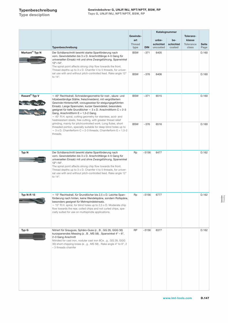
D.147www.lmt-tools.com
Katalognummer
Gewinde- Toleranz-
art unbe- be- klasse
Thread schichtet schichtet Tolerance SeiteTypenbeschreibung type DIN uncoated coated class Page
Markant® Typ N Der Schälanschnitt bewirkt starke Spanförderung nach vorn. Gewindetiefen bis 3 x D. Anschnittlänge 4–5 Gang für universellen Einsatz mit und ohne Zwangsführung. Spanwinkel 12°–14°.The spiral point affects strong chip flow towards the front.Thread depths up to 3 x D. Chamfer 4 to 5 threads, for univer-sal use with and without pitch-controlled feed. Rake angle 12° to 14°.
BSW ~371 6405 D.160
BSW ~376 6406 D.160
Rasant® Typ V 40° Rechtsdrall, Schneidengeometrie für rost-, säure- und hitzebeständige Stähle, freischneidend, mit vergrößertem Gewinde-Hinterschliff, vorzugsweise für steigungsgeführten Einsatz. Lange Spannuten, kurzer Gewindeteil, besonders geeignet für tiefe Grundlöcher 3 x D. Anschnittform C = 2-3 Gang, Anschnittform E = 1,5-2 Gang.
40° R.H. spiral, cutting geometry for stainless, acid- and heatresistant steels, free cutting, with greater thread relief grinding, mainly for pitchcontrolled work. Long flutes, short threaded portion, specially suitable for deep blind holes up to
3 x D. Chamferform C = 2-3 threads, Chamferform E = 1,5-2 threads.
BSW ~371 6515 D.160
BSW ~376 6516 D.160
Typ N Der Schälanschnitt bewirkt starke Spanförderung nach vorn. Gewindetiefen bis 3 x D. Anschnittlänge 4–5 Gang für universellen Einsatz mit und ohne Zwangsführung. Spanwinkel 12°–14°.The spiral point affects strong chip flow towards the front.Thread depths up to 3 x D. Chamfer 4 to 5 threads, for univer-sal use with and without pitch-controlled feed. Rake angle 12° to 14°.
Rp ~5156 6477 D.162
Typ N-R 15 15° Rechtsdrall, für Grundlöcher bis 2,5 x D. Leichte Span-förderung nach hinten, keine Wendelspäne, sondern Rollspäne, besonders geeignet für Mehrspindeleinsatz.
15° R.H. spiral, for blind holes up to 2,5 x D. Moderate chip flow towards the rear, coiled chips and not curled chips, spe-cially suited for use on multispindle applications.
Rp ~5156 6777 D.162
Typ G Nitriert für Grauguss, Sphäro-Guss (z , B , GG 26, GGG 30) kurzspanendes Messing (z , B , MS 58) , Spanwinkel 4° – 6°, 2–3 Gang AnschnittNitrided for cast iron, nodular cast iron 8Ce , g , GG 28, GGG 30) short chipping brass (e , g , MS 58) , Rake angle 4° to 6°, 2 – 3 threads chamfer
RP ~5156 6377 D.162
Typenbeschreibung Type desciption
Gewindebohrer G, UNJF/MJ, NPT/NPTF, BSW, RP Taps G, UNJF/MJ, NPT/NPTF, BSW, RP
Gew
inde
n Th
read
ing
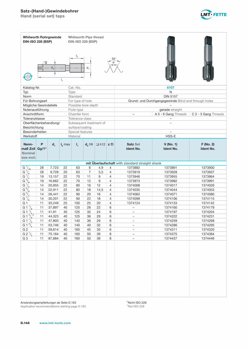
l1
d2
l2
d1
55P
D.148 www.lmt-tools.com
Whitworth Pipe thread DIN-ISO 228 (BSP)
Whitworth Rohrgewinde DIN-ISO 228 (BSP)
1)Nicht ISO-2281)Not ISO-228
Anwendungsempfehlungen ab Seite D.163Application recommendations starting page D.163
Satz-(Hand-)GewindebohrerHand (serial set) taps
Katalog-Nr. Cat.-No. 6107Typ Type NNorm Standard DIN 5157Für Bohrungsart For type of hole Grund- und Durchgangsgewinde Blind and through holesMögliche Gewindetiefe Possible bore depth –Nutenausführung Flute type gerade straightAnschnittform Chamfer form – A 5 - 6 Gang Threads C 2 - 3 Gang ThreadsToleranzklasse Tolerance class –Oberflächenbehandlung/Beschichtung
Subsequent treatment of surface/coating
–
Besonderheiten Special features –Werkstoff Material HSS-E
Nenn-maß Zoll Nominal size inch
PGg/1“
d1 l2 max l1 d2 h9 h12 z Satz SetIdent No.
V (No. 1)Ident No.
F (No. 2)Ident No.
mit Überlaufschaft with standard straight shankG 1/16 28 7,723 22 63 6 4,9 4 1373882 1373891 1373900G 1/8 28 9,728 20 63 7 5,5 4 1373919 1373928 1373937G 1/4 19 13,157 22 70 11 9 4 1373946 1373955 1373964G 3/8 19 16,662 22 70 12 9 4 1373973 1373982 1373991G 1/2 14 20,955 22 80 16 12 4 1374008 1374017 1374026G 5/8 14 22,911 22 80 18 14,5 4 1374035 1374044 1374053G 3/4 14 26,441 22 90 20 16 4 1374062 1374071 1374080G 7/8 14 30,201 22 90 22 18 4 1374099 1374106 1374115G 1 11 33,249 25 100 25 20 4 1374124 1374133 1374142G 1 1/8 11 37,897 40 125 28 22 6 – 1374160 1374179G 1 1/4 11 41,91 40 125 32 24 6 – 1374197 1374204G 1 3/8
1) 11 44,323 40 125 36 29 6 – 1374222 1374231G 1 1/2 11 47,803 40 140 36 29 6 – 1374259 1374268G 1 3/4 11 53,746 40 140 40 32 6 – 1374286 1374295G 2 11 59,614 40 160 45 35 6 – 1374311 1374320G 2 1/2 11 75,184 40 160 50 39 8 – 1374375 1374384G 3 11 87,884 40 160 50 39 8 – 1374437 1374446
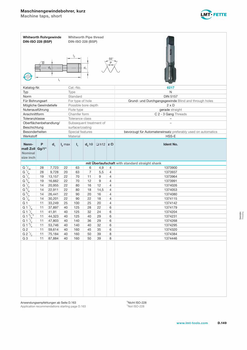
l1
d2
l2
d1
55P
D.149www.lmt-tools.com
Whitworth Pipe thread DIN-ISO 228 (BSP)
Whitworth Rohrgewinde DIN-ISO 228 (BSP)
1)Nicht ISO-2281)Not ISO-228
Anwendungsempfehlungen ab Seite D.163Application recommendations starting page D.163
Maschinengewindebohrer, kurzMachine taps, short
Katalog-Nr. Cat.-No. 6217Typ Type NNorm Standard DIN 5157Für Bohrungsart For type of hole Grund- und Durchgangsgewinde Blind and through holesMögliche Gewindetiefe Possible bore depth 2 x DNutenausführung Flute type gerade straightAnschnittform Chamfer form C 2 - 3 Gang ThreadsToleranzklasse Tolerance class –Oberflächenbehandlung/Beschichtung
Subsequent treatment of surface/coating
–
Besonderheiten Special features bevorzugt für Automateneinsatz preferably used on automaticsWerkstoff Material HSS-E
Nenn-maß Zoll Nominal size inch
PGg/1“
d1 l2 max l1 d2 h9 h12 z Ident No.
mit Überlaufschaft with standard straight shankG 1/16 28 7,723 22 63 6 4,9 4 1373900G 1/8 28 9,728 20 63 7 5,5 4 1373937G 1/4 19 13,157 22 70 11 9 4 1373964G 3/8 19 16,662 22 70 12 9 4 1373991G 1/2 14 20,955 22 80 16 12 4 1374026G 5/8 14 22,911 22 80 18 14,5 4 1374053G 3/4 14 26,441 22 90 20 16 4 1374080G 7/8 14 30,201 22 90 22 18 4 1374115G 1 11 33,249 25 100 25 20 4 1374142G 1 1/8 11 37,897 40 125 28 22 6 1374179G 1 1/4 11 41,91 40 125 32 24 6 1374204G 1 3/8
1) 11 44,323 40 125 40 29 6 1374231G 1 1/2 11 47,803 40 140 36 29 6 1374268G 1 3/4 11 53,746 40 140 40 32 6 1374295G 2 11 59,614 40 160 45 35 6 1374320G 2 1/2 11 75,184 40 160 50 39 8 1374384G 3 11 87,884 40 160 50 39 8 1374446
Gew
inde
n Th
read
ing
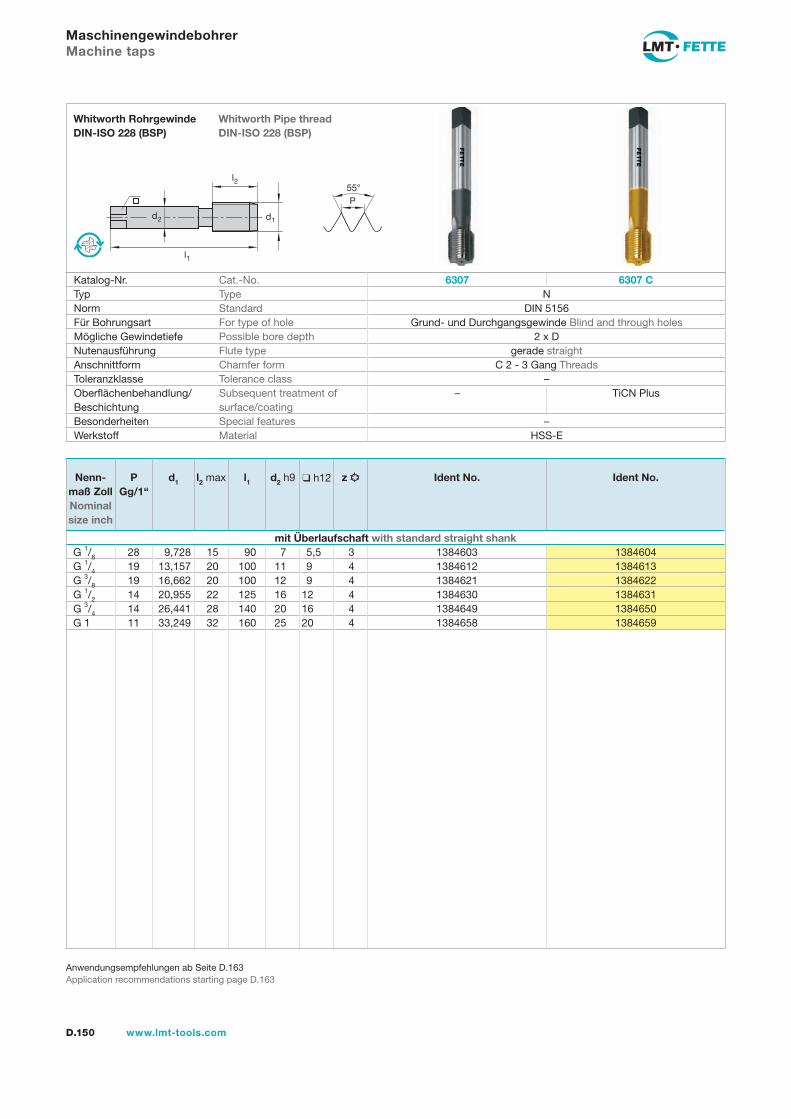
l1
d2
l2
d1
55P
D.150 www.lmt-tools.com
Whitworth Pipe thread DIN-ISO 228 (BSP)
Whitworth Rohrgewinde DIN-ISO 228 (BSP)
Anwendungsempfehlungen ab Seite D.163Application recommendations starting page D.163
MaschinengewindebohrerMachine taps
Katalog-Nr. Cat.-No. 6307 6307 CTyp Type NNorm Standard DIN 5156Für Bohrungsart For type of hole Grund- und Durchgangsgewinde Blind and through holesMögliche Gewindetiefe Possible bore depth 2 x DNutenausführung Flute type gerade straightAnschnittform Chamfer form C 2 - 3 Gang ThreadsToleranzklasse Tolerance class –Oberflächenbehandlung/Beschichtung
Subsequent treatment of surface/coating
– TiCN Plus
Besonderheiten Special features –Werkstoff Material HSS-E
Nenn-maß ZollNominalsize inch
PGg/1“
d1 l2 max l1 d2 h9 h12 z Ident No. Ident No.
mit Überlaufschaft with standard straight shankG 1/8 28 9,728 15 90 7 5,5 3 1384603 1384604G 1/4 19 13,157 20 100 11 9 4 1384612 1384613G 3/8 19 16,662 20 100 12 9 4 1384621 1384622G 1/2 14 20,955 22 125 16 12 4 1384630 1384631G 3/4 14 26,441 28 140 20 16 4 1384649 1384650G 1 11 33,249 32 160 25 20 4 1384658 1384659
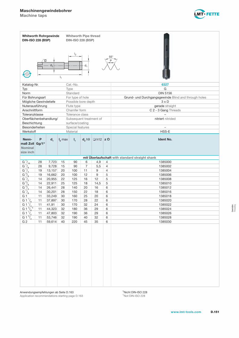
l1
d2
l2
d1
55P
D.151www.lmt-tools.com
Whitworth Pipe thread DIN-ISO 228 (BSP)
Whitworth Rohrgewinde DIN-ISO 228 (BSP)
1)Nicht DIN-ISO 2281)Not DIN-ISO 228
Anwendungsempfehlungen ab Seite D.163Application recommendations starting page D.163
MaschinengewindebohrerMachine taps
Katalog-Nr. Cat.-No. 6327Typ Type GNorm Standard DIN 5156Für Bohrungsart For type of hole Grund- und Durchgangsgewinde Blind and through holesMögliche Gewindetiefe Possible bore depth 3 x DNutenausführung Flute type gerade straightAnschnittform Chamfer form C 2 - 3 Gang ThreadsToleranzklasse Tolerance class –Oberflächenbehandlung/Beschichtung
Subsequent treatment of surface/coating
nitriert nitrided
Besonderheiten Special features –Werkstoff Material HSS-E
Nenn-maß Zoll Nominal size inch
PGg/1“
d1 l2 max l1 d2 h9 h12 z Ident No.
mit Überlaufschaft with standard straight shankG 1/16 28 7,723 15 90 6 4,9 4 1385000G 1/8 28 9,728 15 90 7 5,5 4 1385002G 1/4 19 13,157 20 100 11 9 4 1385004G 3/8 19 16,662 20 100 12 9 5 1385006G 1/2 14 20,955 22 125 16 12 5 1385008G 5/8 14 22,911 25 125 18 14,5 5 1385010G 3/4 14 26,441 28 140 20 16 6 1385012G 7/8 14 30,201 28 150 22 18 6 1385016G 1 11 33,249 30 160 25 20 6 1385018G 1 1/8 11 37,897 30 170 28 22 6 1385020G 1 1/4 11 41,91 30 170 32 24 6 1385022G 1 3/8
1) 11 44,323 32 180 36 29 6 1385024G 1 1/2 11 47,803 32 190 36 29 6 1385026G 1 3/4 11 53,746 32 190 40 32 6 1385028G 2 11 59,614 40 220 45 35 6 1385030
Gew
inde
n Th
read
ing
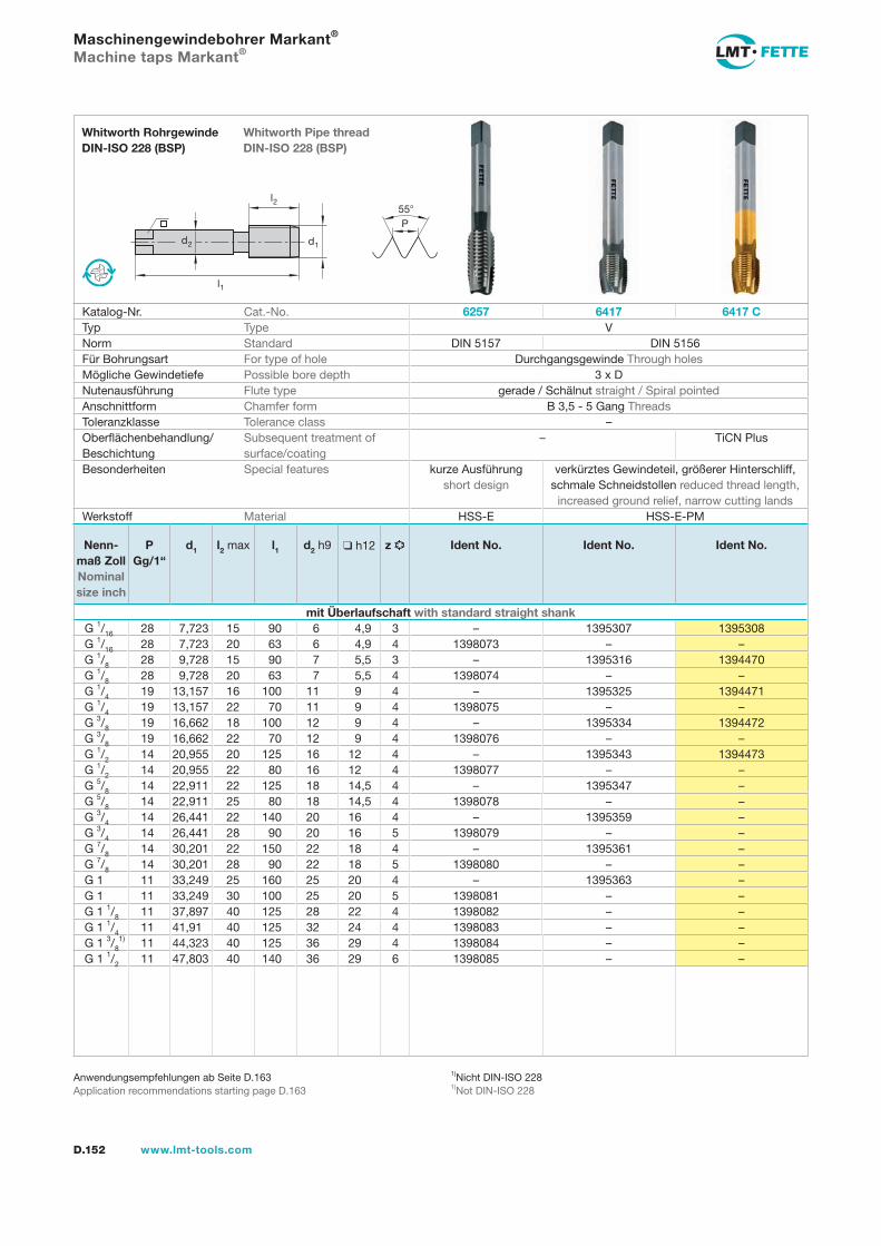
l1
d2
l2
d1
55P
D.152 www.lmt-tools.com
Whitworth Pipe thread DIN-ISO 228 (BSP)
Whitworth Rohrgewinde DIN-ISO 228 (BSP)
Anwendungsempfehlungen ab Seite D.163Application recommendations starting page D.163
Maschinengewindebohrer Markant®
Machine taps Markant®
Katalog-Nr. Cat.-No. 6257 6417 6417 CTyp Type VNorm Standard DIN 5157 DIN 5156Für Bohrungsart For type of hole Durchgangsgewinde Through holesMögliche Gewindetiefe Possible bore depth 3 x DNutenausführung Flute type gerade / Schälnut straight / Spiral pointedAnschnittform Chamfer form B 3,5 - 5 Gang ThreadsToleranzklasse Tolerance class –Oberflächenbehandlung/Beschichtung
Subsequent treatment of surface/coating
– TiCN Plus
Besonderheiten Special features kurze Ausführung short design
verkürztes Gewindeteil, größerer Hinterschliff, schmale Schneidstollen reduced thread length,
increased ground relief, narrow cutting landsWerkstoff Material HSS-E HSS-E-PM
1)Nicht DIN-ISO 2281)Not DIN-ISO 228
Nenn-maß Zoll Nominal size inch
PGg/1“
d1 l2 max l1 d2 h9 h12 z Ident No. Ident No. Ident No.
mit Überlaufschaft with standard straight shankG 1/16 28 7,723 15 90 6 4,9 3 – 1395307 1395308G 1/16 28 7,723 20 63 6 4,9 4 1398073 – –G 1/8 28 9,728 15 90 7 5,5 3 – 1395316 1394470G 1/8 28 9,728 20 63 7 5,5 4 1398074 – –G 1/4 19 13,157 16 100 11 9 4 – 1395325 1394471G 1/4 19 13,157 22 70 11 9 4 1398075 – –G 3/8 19 16,662 18 100 12 9 4 – 1395334 1394472G 3/8 19 16,662 22 70 12 9 4 1398076 – –G 1/2 14 20,955 20 125 16 12 4 – 1395343 1394473G 1/2 14 20,955 22 80 16 12 4 1398077 – –G 5/8 14 22,911 22 125 18 14,5 4 – 1395347 –G 5/8 14 22,911 25 80 18 14,5 4 1398078 – –G 3/4 14 26,441 22 140 20 16 4 – 1395359 –G 3/4 14 26,441 28 90 20 16 5 1398079 – –G 7/8 14 30,201 22 150 22 18 4 – 1395361 –G 7/8 14 30,201 28 90 22 18 5 1398080 – –G 1 11 33,249 25 160 25 20 4 – 1395363 –G 1 11 33,249 30 100 25 20 5 1398081 – –G 1 1/8 11 37,897 40 125 28 22 4 1398082 – –G 1 1/4 11 41,91 40 125 32 24 4 1398083 – –G 1 3/8
1) 11 44,323 40 125 36 29 4 1398084 – –G 1 1/2 11 47,803 40 140 36 29 6 1398085 – –
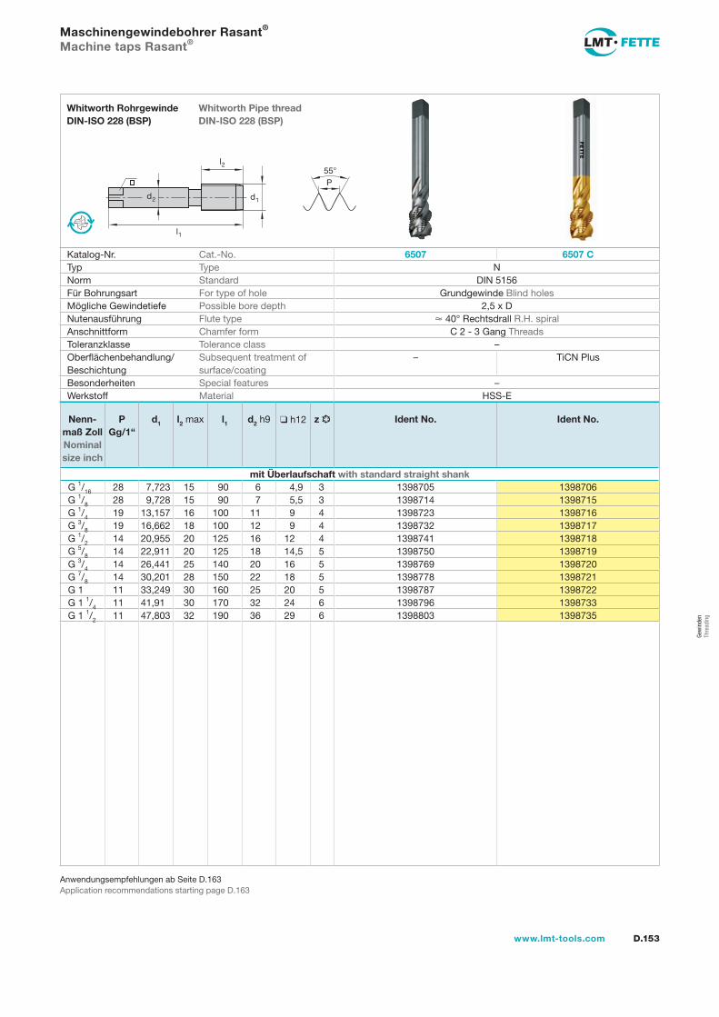
l1
d2
l2
d1
55P
D.153www.lmt-tools.com
Whitworth Pipe thread DIN-ISO 228 (BSP)
Whitworth Rohrgewinde DIN-ISO 228 (BSP)
Anwendungsempfehlungen ab Seite D.163Application recommendations starting page D.163
Maschinengewindebohrer Rasant®
Machine taps Rasant®
Katalog-Nr. Cat.-No. 6507 6507 CTyp Type NNorm Standard DIN 5156Für Bohrungsart For type of hole Grundgewinde Blind holesMögliche Gewindetiefe Possible bore depth 2,5 x DNutenausführung Flute type 40° Rechtsdrall R.H. spiralAnschnittform Chamfer form C 2 - 3 Gang ThreadsToleranzklasse Tolerance class –Oberflächenbehandlung/Beschichtung
Subsequent treatment of surface/coating
– TiCN Plus
Besonderheiten Special features –Werkstoff Material HSS-E
Nenn-maß Zoll Nominal size inch
PGg/1“
d1 l2 max l1 d2 h9 h12 z Ident No. Ident No.
mit Überlaufschaft with standard straight shankG 1/16 28 7,723 15 90 6 4,9 3 1398705 1398706G 1/8 28 9,728 15 90 7 5,5 3 1398714 1398715G 1/4 19 13,157 16 100 11 9 4 1398723 1398716G 3/8 19 16,662 18 100 12 9 4 1398732 1398717G 1/2 14 20,955 20 125 16 12 4 1398741 1398718G 5/8 14 22,911 20 125 18 14,5 5 1398750 1398719G 3/4 14 26,441 25 140 20 16 5 1398769 1398720G 7/8 14 30,201 28 150 22 18 5 1398778 1398721G 1 11 33,249 30 160 25 20 5 1398787 1398722G 1 1/4 11 41,91 30 170 32 24 6 1398796 1398733G 1 1/2 11 47,803 32 190 36 29 6 1398803 1398735
Gew
inde
n Th
read
ing
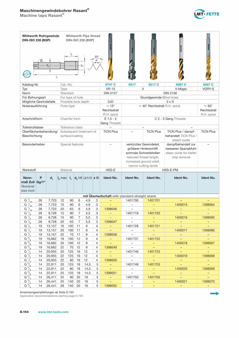
55P
l1
d2
l2
d1
D.154 www.lmt-tools.com
Whitworth Pipe thread DIN-ISO 228 (BSP)
Whitworth Rohrgewinde DIN-ISO 228 (BSP)
Anwendungsempfehlungen ab Seite D.163Application recommendations starting page D.163
Maschinengewindebohrer Rasant®
Machine taps Rasant®
Katalog-Nr. Cat.-No. 6747 C 6517 6517 C 6987 C 6567 CTyp Type VR-15 V V-Magic VDRY-SNorm Standard DIN 5157 DIN 5156Für Bohrungsart For type of hole Grundgewinde Blind holesMögliche Gewindetiefe Possible bore depth 2xD 3 x DNutenausführung Flute type 15°
Rechtsdrall R.H. spiral
40° Rechtsdrall R.H. spiral 50° Rechtsdrall R.H. spiral
Anschnittform Chamfer form E 1,5 - 2 Gang Threads
C 2 - 3 Gang Threads
Toleranzklasse Tolerance class – – –Oberflächenbehandlung/Beschichtung
Subsequent treatment of surface/coating
TiCN Plus – TiCN Plus TiCN Plus / dampf-behandelt TiCN Plus /
steam oxide
TiCN Plus
Besonderheiten Special features – verkürztes Gewindeteil, größerer Hinterschliff,
schmale Schneidstollen reduced thread length, increased ground relief,
narrow cutting lands
dampfbehandelt zur besseren Spanabfuhr stean oxide for better
chip removal
–
Werkstoff Material HSS-E HSS-E-PM
Nenn-maß Zoll Nominal size inch
PGg/1“
d1 l2 max l1 d2 h9 h12 z Ident No. Ident No. Ident No. Ident No. Ident No.
mit Überlaufschaft with standard straight shankG 1/16 28 7,723 12 90 6 4,9 3 – 1401700 1401701 – –G 1/16 28 7,723 15 90 6 4,9 3 – – – 1400015 1398064G 1/16 28 7,723 20 63 6 4,9 3 1398046 – – – –G 1/8 28 9,728 12 90 7 5,5 3 – 1401719 1401720 – –G 1/8 28 9,728 15 90 7 5,5 3 – – – 1400016 1398065G 1/8 28 9,728 20 63 7 5,5 3 1398047 – – – –G 1/4 19 13,157 16 100 11 9 4 – 1401728 1401721 – –G 1/4 19 13,157 20 100 11 9 4 – – – 1400017 1398066G 1/4 19 13,157 22 70 11 9 4 1398048 – – – –G 3/8 19 16,662 18 100 12 9 4 – 1401737 1401722 – –G 3/8 19 16,662 20 100 12 9 4 – – – 1400018 1398067G 3/8 19 16,662 22 70 12 9 4 1398049 – – – –G 1/2 14 20,955 20 125 16 12 4 – 1401746 1401723 – –G 1/2 14 20,955 22 125 16 12 4 – – – 1400019 1398068G 1/2 14 20,955 22 80 16 12 4 1398050 – – – –G 5/8 14 22,911 20 125 18 14,5 5 – 1401748 1401703 – –G 5/8 14 22,911 22 80 18 14,5 5 – – – 1400020 1398069G 5/8 14 22,911 25 125 18 14,5 5 1398051 – – – –G 3/4 14 26,411 22 90 20 16 5 – 1401750 1401705 – –G 3/4 14 26,441 25 140 20 16 5 – – – 1400021 1398070G 3/4 14 26,441 28 140 20 16 5 1398052 – – – –
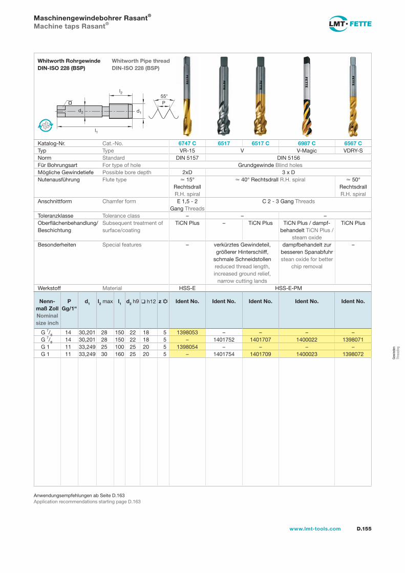
D.155www.lmt-tools.com
Anwendungsempfehlungen ab Seite D.163Application recommendations starting page D.163
Maschinengewindebohrer Rasant®
Machine taps Rasant®
55P
l1
d2
l2
d1
Whitworth Pipe thread DIN-ISO 228 (BSP)
Whitworth Rohrgewinde DIN-ISO 228 (BSP)
Katalog-Nr. Cat.-No. 6747 C 6517 6517 C 6987 C 6567 CTyp Type VR-15 V V-Magic VDRY-SNorm Standard DIN 5157 DIN 5156Für Bohrungsart For type of hole Grundgewinde Blind holesMögliche Gewindetiefe Possible bore depth 2xD 3 x DNutenausführung Flute type 15°
Rechtsdrall R.H. spiral
40° Rechtsdrall R.H. spiral 50° Rechtsdrall R.H. spiral
Anschnittform Chamfer form E 1,5 - 2 Gang Threads
C 2 - 3 Gang Threads
Toleranzklasse Tolerance class – – –Oberflächenbehandlung/Beschichtung
Subsequent treatment of surface/coating
TiCN Plus – TiCN Plus TiCN Plus / dampf-behandelt TiCN Plus /
steam oxide
TiCN Plus
Besonderheiten Special features – verkürztes Gewindeteil, größerer Hinterschliff,
schmale Schneidstollen reduced thread length, increased ground relief,
narrow cutting lands
dampfbehandelt zur besseren Spanabfuhr stean oxide for better
chip removal
–
Werkstoff Material HSS-E HSS-E-PM
Nenn-maß Zoll Nominal size inch
PGg/1“
d1 l2 max l1 d2 h9 h12 z Ident No. Ident No. Ident No. Ident No. Ident No.
G 7/8 14 30,201 28 150 22 18 5 1398053 – – – –G 7/8 14 30,201 28 150 22 18 5 – 1401752 1401707 1400022 1398071G 1 11 33,249 25 100 25 20 5 1398054 – – – –G 1 11 33,249 30 160 25 20 5 – 1401754 1401709 1400023 1398072
Gew
inde
n Th
read
ing
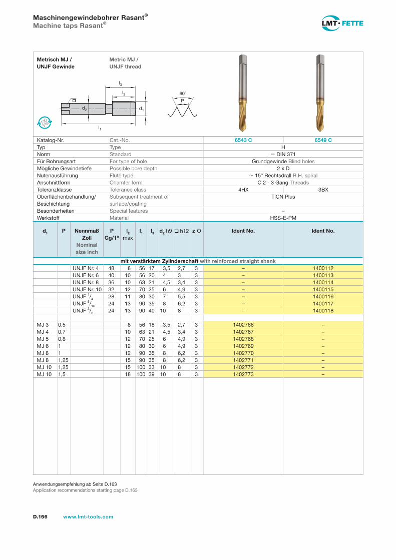
l1
d2
l2
d1
60
P
l3
D.156 www.lmt-tools.com
Metric MJ / UNJF thread
Metrisch MJ / UNJF Gewinde
Anwendungsempfehlung ab Seite D.163Application recommendations starting page D.163
Maschinengewindebohrer Rasant®
Machine taps Rasant®
Katalog-Nr. Cat.-No. 6543 C 6549 CTyp Type HNorm Standard DIN 371Für Bohrungsart For type of hole Grundgewinde Blind holesMögliche Gewindetiefe Possible bore depth 2 x DNutenausführung Flute type 15° Rechtsdrall R.H. spiralAnschnittform Chamfer form C 2 - 3 Gang ThreadsToleranzklasse Tolerance class 4HX 3BXOberflächenbehandlung/Beschichtung
Subsequent treatment of surface/coating
TiCN Plus
Besonderheiten Special features –Werkstoff Material HSS-E-PM
d1 P Nennmaß Zoll
Nominal size inch
PGg/1“
l2 max
l1 l3 d2 h9 h12 z Ident No. Ident No.
mit verstärktem Zylinderschaft with reinforced straight shank UNJF Nr. 4 48 8 56 17 3,5 2,7 3 – 1400112 UNJF Nr. 6 40 10 56 20 4 3 3 – 1400113 UNJF Nr. 8 36 10 63 21 4,5 3,4 3 – 1400114 UNJF Nr. 10 32 12 70 25 6 4,9 3 – 1400115 UNJF 1/4 28 11 80 30 7 5,5 3 – 1400116 UNJF 5/16 24 13 90 35 8 6,2 3 – 1400117 UNJF 3/8 24 13 90 40 10 8 3 – 1400118
MJ 3 0,5 8 56 18 3,5 2,7 3 1402766 –MJ 4 0,7 10 63 21 4,5 3,4 3 1402767 –MJ 5 0,8 12 70 25 6 4,9 3 1402768 –MJ 6 1 12 80 30 6 4,9 3 1402769 –MJ 8 1 12 90 35 8 6,2 3 1402770 –MJ 8 1,25 15 90 35 8 6,2 3 1402771 –MJ 10 1,25 15 100 33 10 8 3 1402772 –MJ 10 1,5 18 100 39 10 8 3 1402773 –
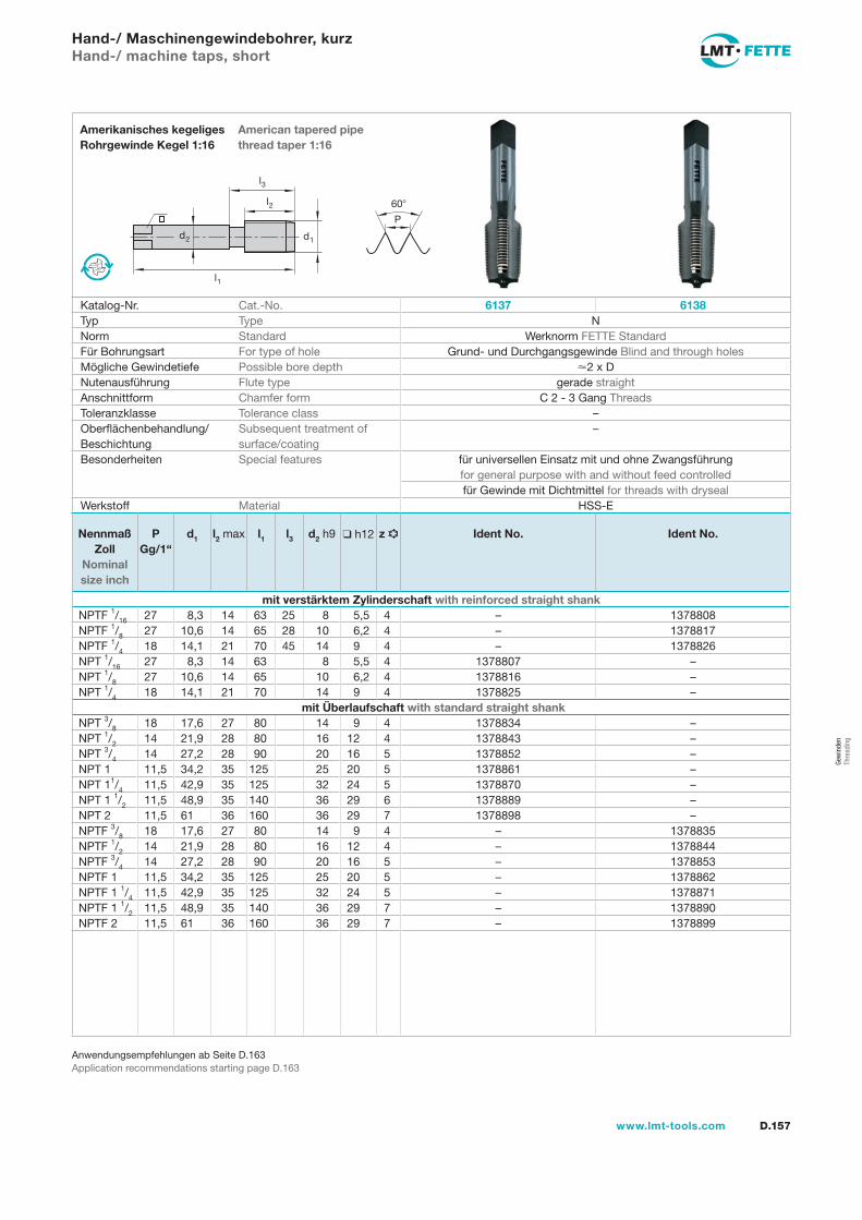
l1
d2
l2
d1
60
P
l3
D.157www.lmt-tools.com
American tapered pipe thread taper 1:16
Amerikanisches kegeliges Rohrgewinde Kegel 1:16
Anwendungsempfehlungen ab Seite D.163Application recommendations starting page D.163
Hand-/ Maschinengewindebohrer, kurzHand-/ machine taps, short
Katalog-Nr. Cat.-No. 6137 6138Typ Type NNorm Standard Werknorm FETTE StandardFür Bohrungsart For type of hole Grund- und Durchgangsgewinde Blind and through holesMögliche Gewindetiefe Possible bore depth 2 x DNutenausführung Flute type gerade straightAnschnittform Chamfer form C 2 - 3 Gang ThreadsToleranzklasse Tolerance class –Oberflächenbehandlung/Beschichtung
Subsequent treatment of surface/coating
–
Besonderheiten Special features für universellen Einsatz mit und ohne Zwangsführung for general purpose with and without feed controlledfür Gewinde mit Dichtmittel for threads with dryseal
Werkstoff Material HSS-E
Nennmaß Zoll
Nominal size inch
PGg/1“
d1 l2 max l1 l3 d2 h9 h12 z Ident No. Ident No.
mit verstärktem Zylinderschaft with reinforced straight shankNPTF 1/16 27 8,3 14 63 25 8 5,5 4 – 1378808NPTF 1/8 27 10,6 14 65 28 10 6,2 4 – 1378817NPTF 1/4 18 14,1 21 70 45 14 9 4 – 1378826NPT 1/16 27 8,3 14 63 8 5,5 4 1378807 –NPT 1/8 27 10,6 14 65 10 6,2 4 1378816 –NPT 1/4 18 14,1 21 70 14 9 4 1378825 –
mit Überlaufschaft with standard straight shankNPT 3/8 18 17,6 27 80 14 9 4 1378834 –NPT 1/2 14 21,9 28 80 16 12 4 1378843 –NPT 3/4 14 27,2 28 90 20 16 5 1378852 –NPT 1 11,5 34,2 35 125 25 20 5 1378861 –NPT 11/4 11,5 42,9 35 125 32 24 5 1378870 –NPT 1 1/2 11,5 48,9 35 140 36 29 6 1378889 –NPT 2 11,5 61 36 160 36 29 7 1378898 –NPTF 3/8 18 17,6 27 80 14 9 4 – 1378835NPTF 1/2 14 21,9 28 80 16 12 4 – 1378844NPTF 3/4 14 27,2 28 90 20 16 5 – 1378853NPTF 1 11,5 34,2 35 125 25 20 5 – 1378862NPTF 1 1/4 11,5 42,9 35 125 32 24 5 – 1378871NPTF 1 1/2 11,5 48,9 35 140 36 29 7 – 1378890NPTF 2 11,5 61 36 160 36 29 7 – 1378899
Gew
inde
n Th
read
ing
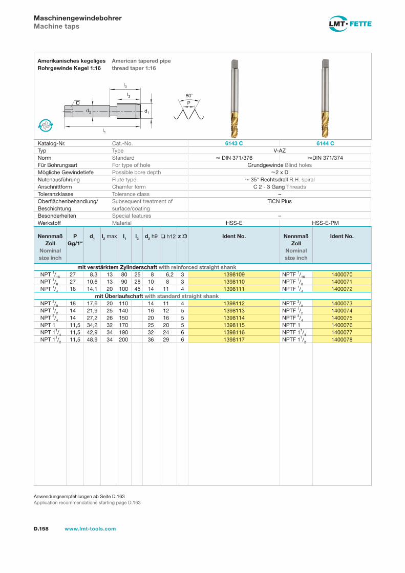
l1
d2
l2
d1
60
P
l3
D.158 www.lmt-tools.com
American tapered pipe thread taper 1:16
Amerikanisches kegeliges Rohrgewinde Kegel 1:16
Anwendungsempfehlungen ab Seite D.163Application recommendations starting page D.163
MaschinengewindebohrerMachine taps
Katalog-Nr. Cat.-No. 6143 C 6144 CTyp Type V-AZNorm Standard DIN 371/376 DIN 371/374Für Bohrungsart For type of hole Grundgewinde Blind holesMögliche Gewindetiefe Possible bore depth 2 x DNutenausführung Flute type 35° Rechtsdrall R.H. spiralAnschnittform Chamfer form C 2 - 3 Gang ThreadsToleranzklasse Tolerance class –Oberflächenbehandlung/Beschichtung
Subsequent treatment of surface/coating
TiCN Plus
Besonderheiten Special features –Werkstoff Material HSS-E HSS-E-PM
Nennmaß Zoll
Nominal size inch
PGg/1“
d1 l2 max l1 l3 d2 h9 h12 z Ident No. Nennmaß Zoll
Nominal size inch
Ident No.
mit verstärktem Zylinderschaft with reinforced straight shankNPT 1/16 27 8,3 13 80 25 8 6,2 3 1398109 NPTF 1/16 1400070NPT 1/8 27 10,6 13 90 28 10 8 3 1398110 NPTF 1/8 1400071NPT 1/4 18 14,1 20 100 45 14 11 4 1398111 NPTF 1/4 1400072
mit Überlaufschaft with standard straight shankNPT 3/8 18 17,6 20 110 14 11 4 1398112 NPTF 3/8 1400073NPT 1/2 14 21,9 25 140 16 12 5 1398113 NPTF 1/2 1400074NPT 3/4 14 27,2 26 150 20 16 5 1398114 NPTF 3/4 1400075NPT 1 11,5 34,2 32 170 25 20 5 1398115 NPTF 1 1400076NPT 11/4 11,5 42,9 34 190 32 24 6 1398116 NPTF 11/4 1400077NPT 11/2 11,5 48,9 34 200 36 29 6 1398117 NPTF 11/2 1400078
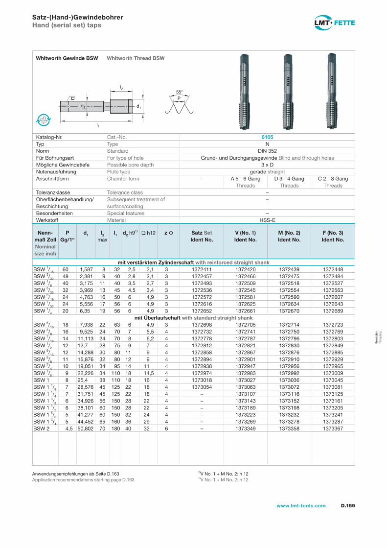
l1
d2
l2
d1
55P
D.159www.lmt-tools.com
Whitworth Thread BSWWhitworth Gewinde BSW
1)V No. 1 + M No. 2: h 121)V No. 1 + M No. 2: h 12
Anwendungsempfehlungen ab Seite D.163Application recommendations starting page D.163
Satz-(Hand-)GewindebohrerHand (serial set) taps
Katalog-Nr. Cat.-No. 6105Typ Type NNorm Standard DIN 352Für Bohrungsart For type of hole Grund- und Durchgangsgewinde Blind and through holesMögliche Gewindetiefe Possible bore depth 3 x DNutenausführung Flute type gerade straightAnschnittform Chamfer form – A 5 - 6 Gang
ThreadsD 3 - 4 Gang
ThreadsC 2 - 3 Gang
ThreadsToleranzklasse Tolerance class –Oberflächenbehandlung/Beschichtung
Subsequent treatment of surface/coating
–
Besonderheiten Special features –Werkstoff Material HSS-E
Nenn-maß Zoll Nominal size inch
PGg/1“
d1 l2 max
l1 d2 h91) h12 z Satz SetIdent No.
V (No. 1)Ident No.
M (No. 2)Ident No.
F (No. 3)Ident No.
mit verstärktem Zylinderschaft with reinforced straight shankBSW 1/16 60 1,587 8 32 2,5 2,1 3 1372411 1372420 1372439 1372448BSW 3/32 48 2,381 9 40 2,8 2,1 3 1372457 1372466 1372475 1372484BSW 1/8 40 3,175 11 40 3,5 2,7 3 1372493 1372509 1372518 1372527BSW 5/32 32 3,969 13 45 4,5 3,4 3 1372536 1372545 1372554 1372563BSW 3/16 24 4,763 16 50 6 4,9 3 1372572 1372581 1372590 1372607BSW 7/32 24 5,556 17 56 6 4,9 3 1372616 1372625 1372634 1372643BSW 1/4 20 6,35 19 56 6 4,9 3 1372652 1372661 1372670 1372689
mit Überlaufschaft with standard straight shankBSW 5/16 18 7,938 22 63 6 4,9 3 1372698 1372705 1372714 1372723BSW 3/8 16 9,525 24 70 7 5,5 4 1372732 1372741 1372750 1372769BSW 7/16 14 11,113 24 70 8 6,2 4 1372778 1372787 1372796 1372803BSW 1/2 12 12,7 28 75 9 7 4 1372812 1372821 1372830 1372849BSW 9/16 12 14,288 30 80 11 9 4 1372858 1372867 1372876 1372885BSW 5/8 11 15,876 32 80 12 9 4 1372894 1372901 1372910 1372929BSW 3/4 10 19,051 34 95 14 11 4 1372938 1372947 1372956 1372965BSW 7/8 9 22,226 34 110 18 14,5 4 1372974 1372983 1372992 1373009BSW 1 8 25,4 38 110 18 16 4 1373018 1373027 1373036 1373045BSW 1 1/8 7 28,576 45 125 22 18 4 1373054 1373063 1373072 1373081BSW 1 1/4 7 31,751 45 125 22 18 4 – 1373107 1373116 1373125BSW 1 3/8 6 34,926 56 150 28 22 4 – 1373143 1373152 1373161BSW 1 1/2 6 38,101 60 150 28 22 4 – 1373189 1373198 1373205BSW 1 5/8 5 41,277 60 150 32 24 4 – 1373223 1373232 1373241BSW 1 3/4 5 44,452 65 160 36 29 4 – 1373269 1373278 1373287BSW 2 4,5 50,802 70 180 40 32 6 – 1373349 1373358 1373367
Gew
inde
n Th
read
ing
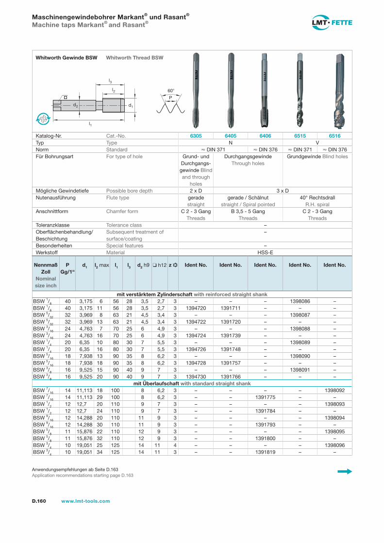
l1
d2
l2
d1
60
P
l3
D.160 www.lmt-tools.com
Whitworth Thread BSWWhitworth Gewinde BSW
Anwendungsempfehlungen ab Seite D.163Application recommendations starting page D.163
Maschinengewindebohrer Markant® und Rasant®
Machine taps Markant® and Rasant®
Katalog-Nr. Cat.-No. 6305 6405 6406 6515 6516Typ Type N VNorm Standard DIN 371 DIN 376 DIN 371 DIN 376Für Bohrungsart For type of hole Grund- und
Durchgangs-gewinde Blind and through
holes
Durchgangsgewinde Through holes
Grundgewinde Blind holes
Mögliche Gewindetiefe Possible bore depth 2 x D 3 x DNutenausführung Flute type gerade
straightgerade / Schälnut
straight / Spiral pointed40° Rechtsdrall
R.H. spiralAnschnittform Chamfer form C 2 - 3 Gang
ThreadsB 3,5 - 5 Gang
ThreadsC 2 - 3 Gang
ThreadsToleranzklasse Tolerance class –Oberflächenbehandlung/Beschichtung
Subsequent treatment of surface/coating
–
Besonderheiten Special features –Werkstoff Material HSS-E
Nennmaß Zoll
Nominal size inch
PGg/1“
d1 l2 max l1 l3 d2 h9 h12 z Ident No. Ident No. Ident No. Ident No. Ident No.
mit verstärktem Zylinderschaft with reinforced straight shankBSW 1/8 40 3,175 6 56 28 3,5 2,7 3 – – – 1398086 –BSW 1/8 40 3,175 11 56 28 3,5 2,7 3 1394720 1391711 – – –BSW 5/32 32 3,969 8 63 21 4,5 3,4 3 – – – 1398087 –BSW 5/32 32 3,969 13 63 21 4,5 3,4 3 1394722 1391720 – – –BSW 3/16 24 4,763 7 70 25 6 4,9 3 – – – 1398088 –BSW 3/16 24 4,763 16 70 25 6 4,9 3 1394724 1391739 – – –BSW 1/4 20 6,35 10 80 30 7 5,5 3 – – – 1398089 –BSW 1/4 20 6,35 16 80 30 7 5,5 3 1394726 1391748 – – –BSW 5/16 18 7,938 13 90 35 8 6,2 3 – – – 1398090 –BSW 5/16 18 7,938 18 90 35 8 6,2 3 1394728 1391757 – – –BSW 3/8 16 9,525 15 90 40 9 7 3 – – – 1398091 –BSW 3/8 16 9,525 20 90 40 9 7 3 1394730 1391766 – – –
mit Überlaufschaft with standard straight shankBSW 7/16 14 11,113 18 100 8 6,2 3 – – – – 1398092BSW 7/16 14 11,113 29 100 8 6,2 3 – – 1391775 – –BSW 1/2 12 12,7 20 110 9 7 3 – – – – 1398093BSW 1/2 12 12,7 24 110 9 7 3 – – 1391784 – –BSW 9/16 12 14,288 20 110 11 9 3 – – – – 1398094BSW 9/16 12 14,288 30 110 11 9 3 – – 1391793 – –BSW 5/8 11 15,876 22 110 12 9 3 – – – – 1398095BSW 5/8 11 15,876 32 110 12 9 3 – – 1391800 – –BSW 3/4 10 19,051 25 125 14 11 4 – – – – 1398096BSW 3/4 10 19,051 34 125 14 11 3 – – 1391819 – –
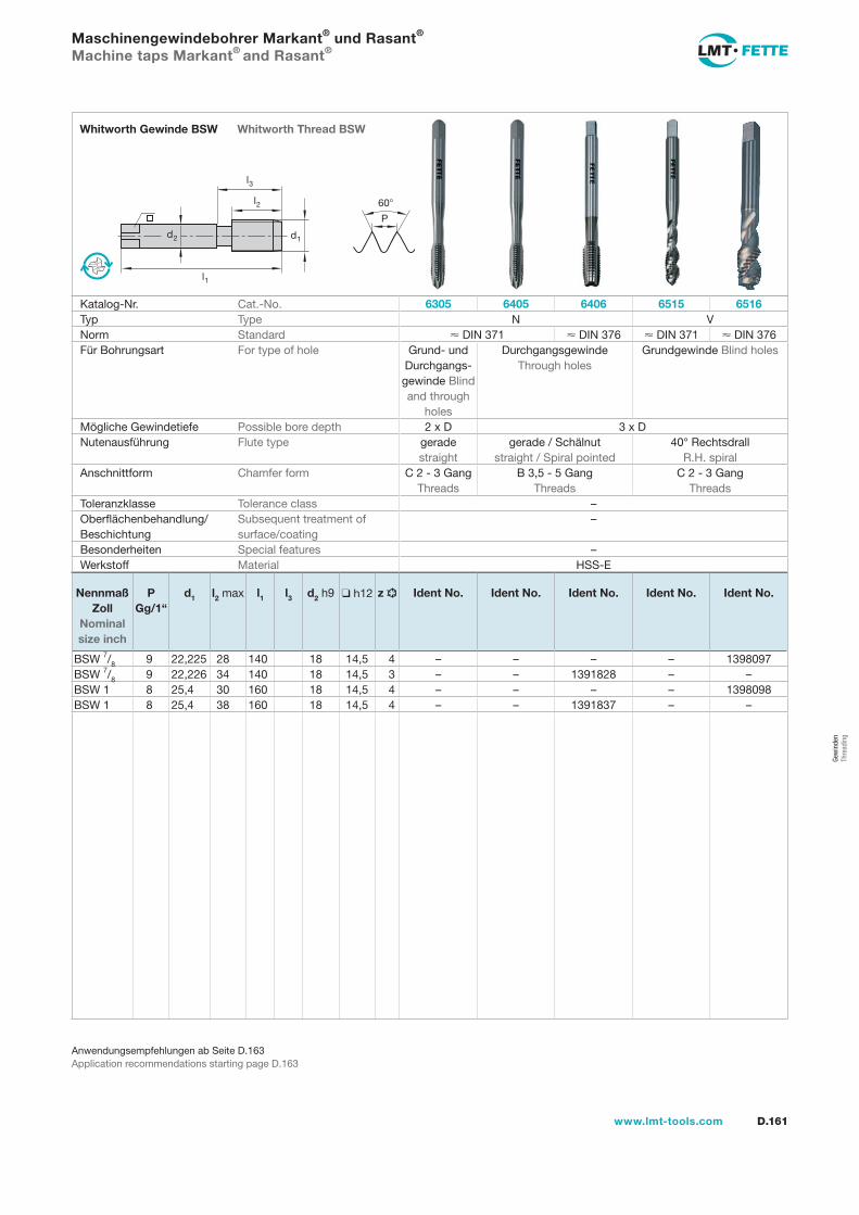
D.161www.lmt-tools.com
Anwendungsempfehlungen ab Seite D.163Application recommendations starting page D.163
l1
d2
l2
d1
60
P
l3
Whitworth Thread BSWWhitworth Gewinde BSW
Maschinengewindebohrer Markant® und Rasant®
Machine taps Markant® and Rasant®
Katalog-Nr. Cat.-No. 6305 6405 6406 6515 6516Typ Type N VNorm Standard DIN 371 DIN 376 DIN 371 DIN 376Für Bohrungsart For type of hole Grund- und
Durchgangs-gewinde Blind and through
holes
Durchgangsgewinde Through holes
Grundgewinde Blind holes
Mögliche Gewindetiefe Possible bore depth 2 x D 3 x DNutenausführung Flute type gerade
straightgerade / Schälnut
straight / Spiral pointed40° Rechtsdrall
R.H. spiralAnschnittform Chamfer form C 2 - 3 Gang
ThreadsB 3,5 - 5 Gang
ThreadsC 2 - 3 Gang
ThreadsToleranzklasse Tolerance class –Oberflächenbehandlung/Beschichtung
Subsequent treatment of surface/coating
–
Besonderheiten Special features –Werkstoff Material HSS-E
Nennmaß Zoll
Nominal size inch
PGg/1“
d1 l2 max l1 l3 d2 h9 h12 z Ident No. Ident No. Ident No. Ident No. Ident No.
BSW 7/8 9 22,225 28 140 18 14,5 4 – – – – 1398097BSW 7/8 9 22,226 34 140 18 14,5 3 – – 1391828 – –BSW 1 8 25,4 30 160 18 14,5 4 – – – – 1398098BSW 1 8 25,4 38 160 18 14,5 4 – – 1391837 – –
Gew
inde
n Th
read
ing
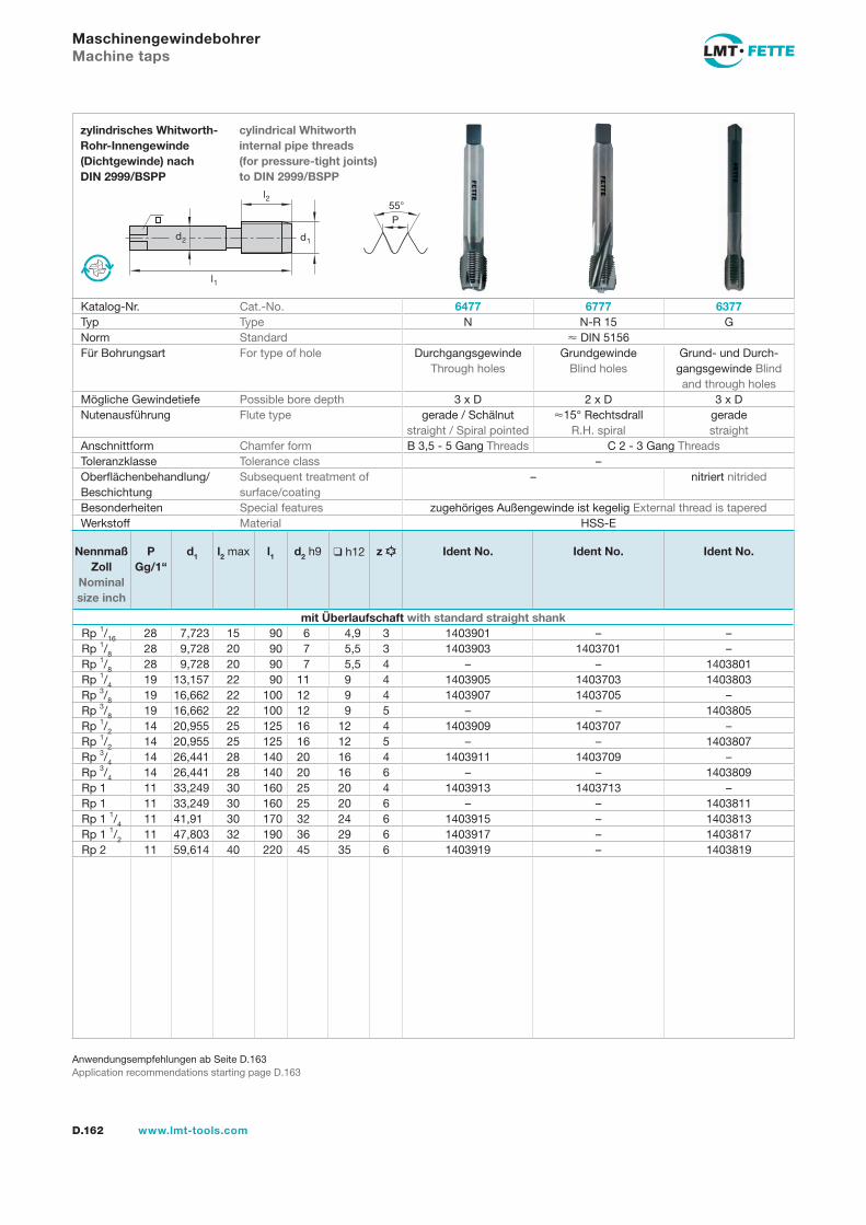
l1
d2
l2
d1
55P
D.162 www.lmt-tools.com
cylindrical Whitworthinternal pipe threads(for pressure-tight joints) to DIN 2999/BSPP
zylindrisches Whitworth-Rohr-Innengewinde(Dichtgewinde) nachDIN 2999/BSPP
Anwendungsempfehlungen ab Seite D.163Application recommendations starting page D.163
MaschinengewindebohrerMachine taps
Katalog-Nr. Cat.-No. 6477 6777 6377Typ Type N N-R 15 GNorm Standard DIN 5156Für Bohrungsart For type of hole Durchgangsgewinde
Through holesGrundgewinde
Blind holesGrund- und Durch-
gangsgewinde Blind and through holes
Mögliche Gewindetiefe Possible bore depth 3 x D 2 x D 3 x DNutenausführung Flute type gerade / Schälnut
straight / Spiral pointed15° Rechtsdrall
R.H. spiralgerade straight
Anschnittform Chamfer form B 3,5 - 5 Gang Threads C 2 - 3 Gang ThreadsToleranzklasse Tolerance class –Oberflächenbehandlung/Beschichtung
Subsequent treatment of surface/coating
– nitriert nitrided
Besonderheiten Special features zugehöriges Außengewinde ist kegelig External thread is taperedWerkstoff Material HSS-E
Nennmaß Zoll
Nominal size inch
PGg/1“
d1 l2 max l1 d2 h9 h12 z Ident No. Ident No. Ident No.
mit Überlaufschaft with standard straight shankRp 1/16 28 7,723 15 90 6 4,9 3 1403901 – –Rp 1/8 28 9,728 20 90 7 5,5 3 1403903 1403701 –Rp 1/8 28 9,728 20 90 7 5,5 4 – – 1403801Rp 1/4 19 13,157 22 90 11 9 4 1403905 1403703 1403803Rp 3/8 19 16,662 22 100 12 9 4 1403907 1403705 –Rp 3/8 19 16,662 22 100 12 9 5 – – 1403805Rp 1/2 14 20,955 25 125 16 12 4 1403909 1403707 –Rp 1/2 14 20,955 25 125 16 12 5 – – 1403807Rp 3/4 14 26,441 28 140 20 16 4 1403911 1403709 –Rp 3/4 14 26,441 28 140 20 16 6 – – 1403809Rp 1 11 33,249 30 160 25 20 4 1403913 1403713 –Rp 1 11 33,249 30 160 25 20 6 – – 1403811Rp 1 1/4 11 41,91 30 170 32 24 6 1403915 – 1403813Rp 1 1/2 11 47,803 32 190 36 29 6 1403917 – 1403817Rp 2 11 59,614 40 220 45 35 6 1403919 – 1403819
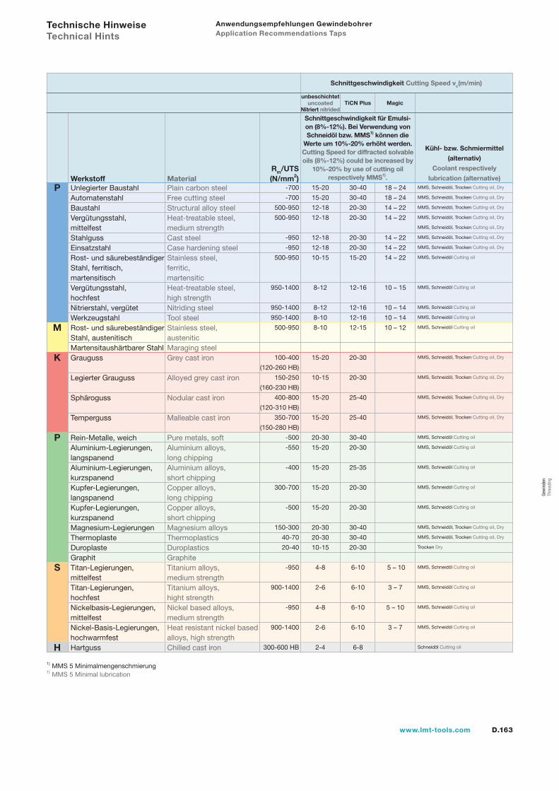
D.163www.lmt-tools.com
P
S
H
P
K
M
1) MMS 5 Minimalmengenschmierung 1) MMS 5 Minimal lubrication
Kühl- bzw. Schmiermittel
(alternativ)
Coolant respectively
lubrication (alternative)Rm/UTS(N/mm2)
Unlegierter Baustahl Plain carbon steelAutomatenstahl Free cutting steelBaustahl Structural alloy steelVergütungsstahl, Heat-treatable steel, mittelfest medium strengthStahlguss Cast steelEinsatzstahl Case hardening steel Rost- und säurebeständiger Stainless steel, Stahl, ferritisch, ferritic,martensitisch martensiticVergütungsstahl, Heat-treatable steel, hochfest high strengthNitrierstahl, vergütet Nitriding steelWerkzeugstahl Tool steelRost- und säurebeständiger Stainless steel,Stahl, austenitisch austeniticMartensitaushärtbarer Stahl Maraging steelGrauguss Grey cast iron
Legierter Grauguss Alloyed grey cast iron
Sphäroguss Nodular cast iron
Temperguss Malleable cast iron
Rein-Metalle, weich Pure metals, softAluminium-Legierungen, Aluminium alloys, langspanend long chippingAluminium-Legierungen, Aluminium alloys,kurzspanend short chippingKupfer-Legierungen, Copper alloys,langspanend long chippingKupfer-Legierungen, Copper alloys,kurzspanend short chippingMagnesium-Legierungen Magnesium alloysThermoplaste ThermoplasticsDuroplaste DuroplasticsGraphit GraphiteTitan-Legierungen, Titanium alloys,mittelfest medium strengthTitan-Legierungen, Titanium alloys,hochfest hight strengthNickelbasis-Legierungen, Nickel based alloys,mittelfest medium strengthNickel-Basis-Legierungen, Heat resistant nickel basedhochwarmfest alloys, high strengthHartguss Chilled cast iron
Werkstoff Material -700
-700
500-950
500-950
-950
-950
500-950
950-1400
950-1400
950-1400
500-950
100-400
(120-260 HB)
150-250
(160-230 HB)
400-800
(120-310 HB)
350-700
(150-280 HB)
-500
-550
-400
300-700
-500
150-300
40-70
20-40
-950
900-1400
-950
900-1400
300-600 HB
30-40
30-40
20-30
20-30
20-30
20-30
15-20
12-16
12-16
12-16
12-15
20-30
20-30
25-40
25-40
30-40
20-30
25-35
20-30
20-30
30-40
30-40
20-30
6-10
6-10
6-10
6-10
6-8
15-20
15-20
12-18
12-18
12-18
12-18
10-15
8-12
8-12
8-10
8-10
15-20
10-15
15-20
15-20
20-30
15-20
15-20
15-20
15-20
20-30
20-30
10-15
4-8
2-6
4-8
2-6
2-4
18 – 24
18 – 24
14 – 22
14 – 22
14 – 22
14 – 22
14 – 22
10 – 15
10 – 14
10 – 14
10 – 12
5 – 10
3 – 7
5 – 10
3 – 7
MMS, Schneidöl, Trocken Cutting oil, Dry
MMS, Schneidöl, Trocken Cutting oil, Dry
MMS, Schneidöl, Trocken Cutting oil, Dry
MMS, Schneidöl, Trocken Cutting oil, Dry
MMS, Schneidöl, Trocken Cutting oil, Dry
MMS, Schneidöl, Trocken Cutting oil, Dry
MMS, Schneidöl, Trocken Cutting oil, Dry
MMS, Schneidöl Cutting oil
MMS, Schneidöl Cutting oil
MMS, Schneidöl Cutting oil
MMS, Schneidöl Cutting oil
MMS, Schneidöl Cutting oil
MMS, Schneidöl, Trocken Cutting oil, Dry
MMS, Schneidöl, Trocken Cutting oil, Dry
MMS, Schneidöl, Trocken Cutting oil, Dry
MMS, Schneidöl, Trocken Cutting oil, Dry
MMS, Schneidöl Cutting oil
MMS, Schneidöl Cutting oil
MMS, Schneidöl Cutting oil
MMS, Schneidöl Cutting oil
MMS, Schneidöl Cutting oil
MMS, Schneidöl, Trocken Cutting oil, Dry
MMS, Schneidöl, Trocken Cutting oil, Dry
Trocken Dry
MMS, Schneidöl Cutting oil
MMS, Schneidöl Cutting oil
MMS, Schneidöl Cutting oil
MMS, Schneidöl Cutting oil
Schneidöl Cutting oil
Schnittgeschwindigkeit für Emulsi-on (8%-12%). Bei Verwendung von Schneidöl bzw. MMS1) können die
Werte um 10%-20% erhöht werden.Cutting Speed for diffracted solvable oils (8%-12%) could be increased by
10%-20% by use of cutting oil respectively MMS1).
unbeschichtet uncoated TiCN Plus Magic
Schnittgeschwindigkeit Cutting Speed vc(m/min)
Anwendungsempfehlungen Gewindebohrer Application Recommendations Taps
Technische Hinweise Technical Hints
Nitriert nitrided
Gew
inde
n Th
read
ing
D.164 www.lmt-tools.com
Gewindeformer Forming Taps

D.165www.lmt-tools.com
Gewindeformer Forming taps
D.166 Auswahlübersichten Selection tables
D.167 Typenbeschreibungen Type descriptions
D.170 Technische Hinweise HPF-High Perfomance Forming Technical hints HPF-High Perfomance Forming
Typen Type HPF D.172, D.178, D.182, D.184, D.186
VHM-IK D.174 N D.175, D.179, D.183, D.185, D.187 S D.175, D.179, D.183, D.185, D.187 S-IK D.176, D.180
D.188 Anwendungsempfehlungen Application recommendations
Gew
inde
n Th
read
ing
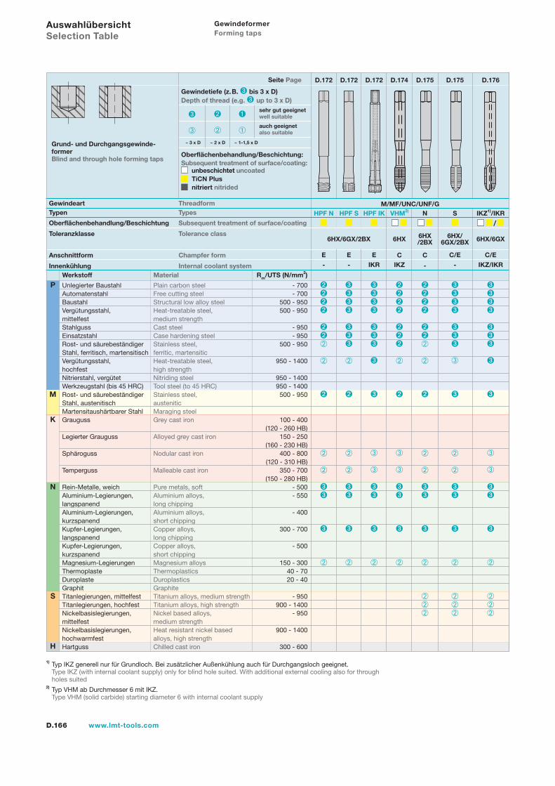
D.166 www.lmt-tools.com
Gewindeformer Forming taps
Typen Types
Oberflächenbehandlung/Beschichtung Subsequent treatment of surface/coating
Toleranzklasse Tolerance class
Anschnittform Champfer form
Innenkühlung Internal coolant system
Grund- und Durchgangsgewinde-formerBlind and through hole forming taps
E
Seite Page D.172
Werkstoff Material Rm/UTS (N/mm2)
Unlegierter Baustahl Plain carbon steel - 700Automatenstahl Free cutting steel - 700Baustahl Structural low alloy steel 500 - 950Vergütungsstahl, Heat-treatable steel, 500 - 950mittelfest medium strengthStahlguss Cast steel - 950Einsatzstahl Case hardening steel - 950Rost- und säurebeständiger Stainless steel, 500 - 950Stahl, ferritisch, martensitisch ferritic, martensiticVergütungsstahl, Heat-treatable steel, 950 - 1400hochfest high strengthNitrierstahl, vergütet Nitriding steel 950 - 1400Werkzeugstahl (bis 45 HRC) Tool steel (to 45 HRC) 950 - 1400Rost- und säurebeständiger Stainless steel, 500 - 950Stahl, austenitisch austeniticMartensitaushärtbarer Stahl Maraging steelGrauguss Grey cast iron 100 - 400 (120 - 260 HB)Legierter Grauguss Alloyed grey cast iron 150 - 250 (160 - 230 HB)Sphäroguss Nodular cast iron 400 - 800 (120 - 310 HB)Temperguss Malleable cast iron 350 - 700 (150 - 280 HB)Rein-Metalle, weich Pure metals, soft - 500Aluminium-Legierungen, Aluminium alloys, - 550langspanend long chippingAluminium-Legierungen, Aluminium alloys, - 400kurzspanend short chippingKupfer-Legierungen, Copper alloys, 300 - 700langspanend long chippingKupfer-Legierungen, Copper alloys, - 500kurzspanend short chippingMagnesium-Legierungen Magnesium alloys 150 - 300Thermoplaste Thermoplastics 40 - 70Duroplaste Duroplastics 20 - 40Graphit GraphiteTitanlegierungen, mittelfest Titanium alloys, medium strength - 950Titanlegierungen, hochfest Titanium alloys, high strength 900 - 1400Nickelbasislegierungen, Nickel based alloys, - 950mittelfest medium strengthNickelbasislegierungen, Heat resistant nickel based 900 - 1400hochwarmfest alloys, high strengthHartguss Chilled cast iron 300 - 600
Oberflächenbehandlung/Beschichtung:Subsequent treatment of surface/coating: unbeschichtet uncoated TiCN Plus nitriert nitrided
Gewindetiefe (z.B. bis 3 x D)Depth of thread (e.g. up to 3 x D)
~ 1-1,5 x D~ 2 x D~ 3 x D
sehr gut geeignetwell suitable
auch geeignetalso suitable
Auswahlübersicht Selection Table
1) Typ IKZ generell nur für Grundloch. Bei zusätzlicher Außenkühlung auch für Durchgangsloch geeignet. Type IKZ (with internal coolant supply) only for blind hole suited. With additional external cooling also for through holes suited 2) Typ VHM ab Durchmesser 6 mit IKZ. Type VHM (solid carbide) starting diameter 6 with internal coolant supply
Gewindeart Threadform M/MF/UNC/UNF/G
K
N
S
H
P
M
HPF N
6HX/6GX/2BX
-
E
HPF S
-
E
HPF IK
IKRC
VHM2)
IKZ
6HX
C/E
S
-
6HX/6GX/2BX 6HX/6GX
IKZ1)/IKR
C
N
-
6HX/2BX
C/E
IKZ/IKR
/
D.172 D.172 D.174 D.175 D.175 D.176
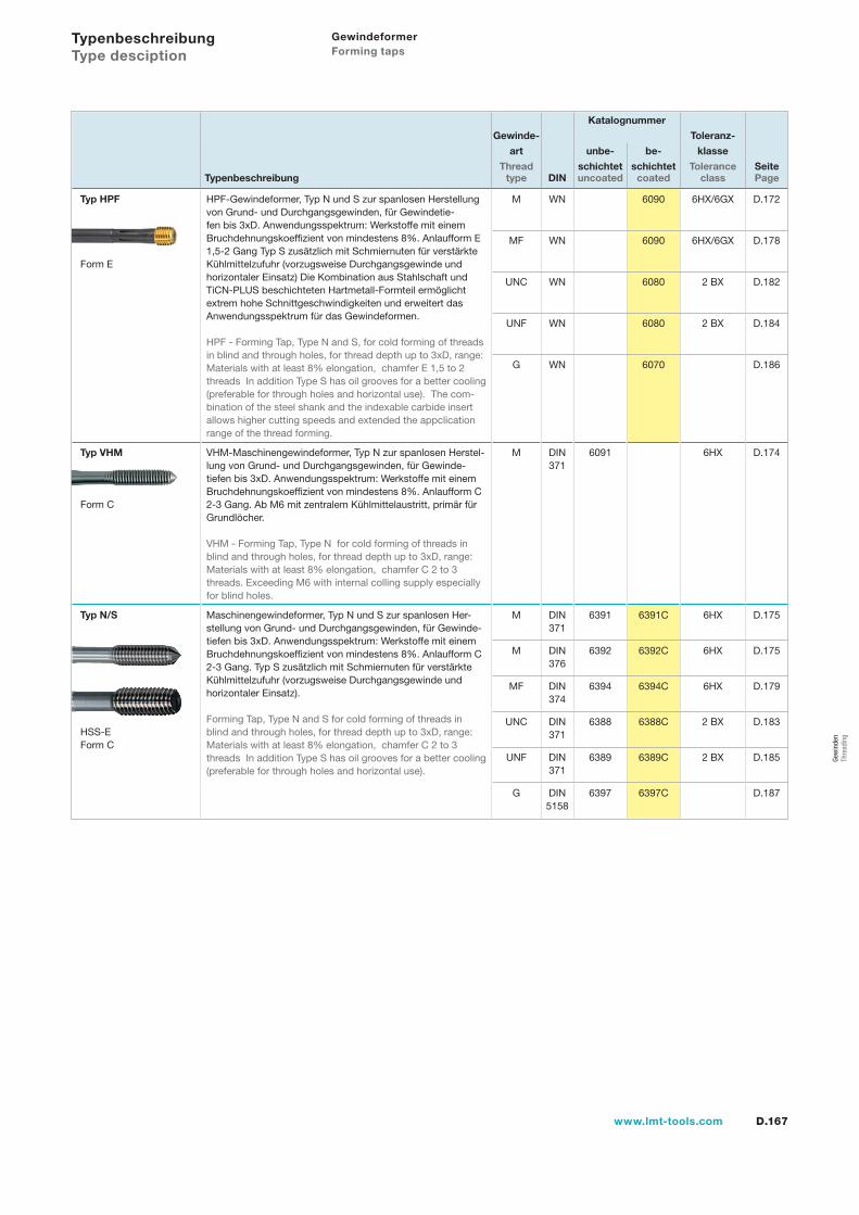
D.167www.lmt-tools.com
Katalognummer
Gewinde- Toleranz-
art unbe- be- klasse
Thread schichtet schichtet Tolerance SeiteTypenbeschreibung type DIN uncoated coated class Page
Typ HPF
Form E
HPF-Gewindeformer, Typ N und S zur spanlosen Herstellung von Grund- und Durchgangsgewinden, für Gewindetie-fen bis 3xD. Anwendungsspektrum: Werkstoffe mit einem Bruchdehnungskoeffizient von mindestens 8%. Anlaufform E 1,5-2 Gang Typ S zusätzlich mit Schmiernuten für verstärkte Kühlmittelzufuhr (vorzugsweise Durchgangsgewinde und horizontaler Einsatz) Die Kombination aus Stahlschaft und TiCN-PLUS beschichteten Hartmetall-Formteil ermöglicht extrem hohe Schnittgeschwindigkeiten und erweitert das Anwendungsspektrum für das Gewindeformen.
HPF - Forming Tap, Type N and S, for cold forming of threads in blind and through holes, for thread depth up to 3xD, range: Materials with at least 8% elongation, chamfer E 1,5 to 2 threads In addition Type S has oil grooves for a better cooling (preferable for through holes and horizontal use). The com-bination of the steel shank and the indexable carbide insert allows higher cutting speeds and extended the appclication range of the thread forming.
M WN 6090 6HX/6GX D.172
MF WN 6090 6HX/6GX D.178
UNC WN 6080 2 BX D.182
UNF WN 6080 2 BX D.184
G WN 6070 D.186
Typ VHM
Form C
VHM-Maschinengewindeformer, Typ N zur spanlosen Herstel-lung von Grund- und Durchgangsgewinden, für Gewinde-tiefen bis 3xD. Anwendungsspektrum: Werkstoffe mit einem Bruchdehnungskoeffizient von mindestens 8%. Anlaufform C 2-3 Gang. Ab M6 mit zentralem Kühlmittelaustritt, primär für Grundlöcher.
VHM - Forming Tap, Type N for cold forming of threads in blind and through holes, for thread depth up to 3xD, range: Materials with at least 8% elongation, chamfer C 2 to 3 threads. Exceeding M6 with internal colling supply especially for blind holes.
M DIN 371
6091 6HX D.174
Typ N/S
HSS-E Form C
Maschinengewindeformer, Typ N und S zur spanlosen Her-stellung von Grund- und Durchgangsgewinden, für Gewinde-tiefen bis 3xD. Anwendungsspektrum: Werkstoffe mit einem Bruchdehnungskoeffizient von mindestens 8%. Anlaufform C 2-3 Gang. Typ S zusätzlich mit Schmiernuten für verstärkte Kühlmittelzufuhr (vorzugsweise Durchgangsgewinde und horizontaler Einsatz).
Forming Tap, Type N and S for cold forming of threads in blind and through holes, for thread depth up to 3xD, range: Materials with at least 8% elongation, chamfer C 2 to 3 threads In addition Type S has oil grooves for a better cooling (preferable for through holes and horizontal use).
M DIN 371
6391 6391C 6HX D.175
M DIN 376
6392 6392C 6HX D.175
MF DIN 374
6394 6394C 6HX D.179
UNC DIN 371
6388 6388C 2 BX D.183
UNF DIN 371
6389 6389C 2 BX D.185
G DIN 5158
6397 6397C D.187
Typenbeschreibung Type desciption
Gewindeformer Forming taps
Gew
inde
n Th
read
ing
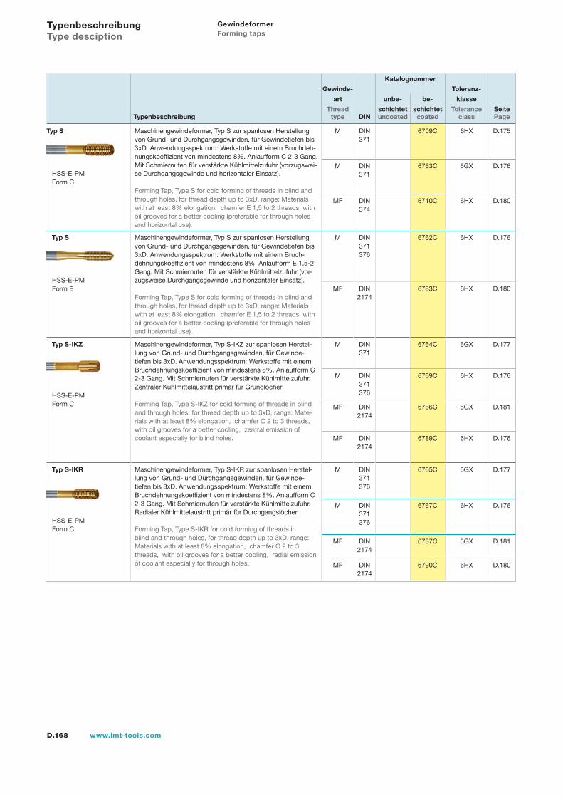
D.168 www.lmt-tools.com
Katalognummer
Gewinde- Toleranz-
art unbe- be- klasse
Thread schichtet schichtet Tolerance SeiteTypenbeschreibung type DIN uncoated coated class Page
Typ S
HSS-E-PM Form C
Maschinengewindeformer, Typ S zur spanlosen Herstellung von Grund- und Durchgangsgewinden, für Gewindetiefen bis 3xD. Anwendungsspektrum: Werkstoffe mit einem Bruchdeh-nungskoeffizient von mindestens 8%. Anlaufform C 2-3 Gang. Mit Schmiernuten für verstärkte Kühlmittelzufuhr (vorzugswei-se Durchgangsgewinde und horizontaler Einsatz).
Forming Tap, Type S for cold forming of threads in blind and through holes, for thread depth up to 3xD, range: Materials with at least 8% elongation, chamfer E 1,5 to 2 threads, with oil grooves for a better cooling (preferable for through holes and horizontal use).
M DIN 371
6709C 6HX D.175
M DIN 371
6763C 6GX D.176
MF DIN 374
6710C 6HX D.180
Typ S
HSS-E-PM Form E
Maschinengewindeformer, Typ S zur spanlosen Herstellung von Grund- und Durchgangsgewinden, für Gewindetiefen bis 3xD. Anwendungsspektrum: Werkstoffe mit einem Bruch-dehnungskoeffizient von mindestens 8%. Anlaufform E 1,5-2 Gang. Mit Schmiernuten für verstärkte Kühlmittelzufuhr (vor-zugsweise Durchgangsgewinde und horizontaler Einsatz).
Forming Tap, Type S for cold forming of threads in blind and through holes, for thread depth up to 3xD, range: Materials with at least 8% elongation, chamfer E 1,5 to 2 threads, with oil grooves for a better cooling (preferable for through holes and horizontal use).
M DIN 371376
6762C 6HX D.176
MF DIN 2174
6783C 6HX D.180
Typ S-IKZ
HSS-E-PM Form C
Maschinengewindeformer, Typ S-IKZ zur spanlosen Herstel-lung von Grund- und Durchgangsgewinden, für Gewinde-tiefen bis 3xD. Anwendungsspektrum: Werkstoffe mit einem Bruchdehnungskoeffizient von mindestens 8%. Anlaufform C 2-3 Gang. Mit Schmiernuten für verstärkte Kühlmittelzufuhr. Zentraler Kühlmittelaustritt primär für Grundlöcher
Forming Tap, Type S-IKZ for cold forming of threads in blind and through holes, for thread depth up to 3xD, range: Mate-rials with at least 8% elongation, chamfer C 2 to 3 threads, with oil grooves for a better cooling, zentral emission of coolant especially for blind holes.
M DIN371
6764C 6GX D.177
M DIN 371376
6769C 6HX D.176
MF DIN2174
6786C 6GX D.181
MF DIN 2174
6789C 6HX D.176
Typ S-IKR
HSS-E-PM Form C
Maschinengewindeformer, Typ S-IKR zur spanlosen Herstel-lung von Grund- und Durchgangsgewinden, für Gewinde-tiefen bis 3xD. Anwendungsspektrum: Werkstoffe mit einem Bruchdehnungskoeffizient von mindestens 8%. Anlaufform C 2-3 Gang. Mit Schmiernuten für verstärkte Kühlmittelzufuhr. Radialer Kühlmittelaustritt primär für Durchgangslöcher.
Forming Tap, Type S-IKR for cold forming of threads in blind and through holes, for thread depth up to 3xD, range: Materials with at least 8% elongation, chamfer C 2 to 3 threads, with oil grooves for a better cooling, radial emission of coolant especially for through holes.
M DIN 371376
6765C 6GX D.177
M DIN 371376
6767C 6HX D.176
MF DIN 2174
6787C 6GX D.181
MF DIN2174
6790C 6HX D.180
Typenbeschreibung Type desciption
Gewindeformer Forming taps
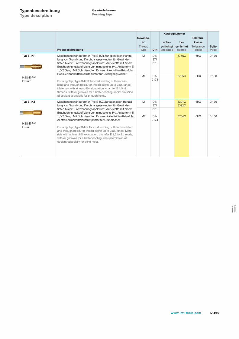
D.169www.lmt-tools.com
Katalognummer
Gewinde- Toleranz-
art unbe- be- klasse
Thread schichtet schichtet Tolerance SeiteTypenbeschreibung type DIN uncoated coated class Page
Typ S-IKR
HSS-E-PM Form E
Maschinengewindeformer, Typ S-IKR Zur spanlosen Herstel-lung von Grund- und Durchgangsgewinden, für Gewinde-tiefen bis 3xD. Anwendungsspektrum: Werkstoffe mit einem Bruchdehnungskoeffizient von mindestens 8%. Anlaufform E 1,5-2 Gang. Mit Schmiernuten für verstärke Kühlmittelzufuhr. Radialer Kühlmittelaustritt primär für Durchgangslöcher
Forming Tap, Type S-IKR, for cold forming of threads in blind and through holes, for thread depth up to 3xD, range: Materials with at least 8% elongation, chamfer E 1,5 -2 threads, with oil grooves for a better cooling, radial emission of coolant especially for through holes.
M DIN 371376
6766C 6HX D.176
MF DIN 2174
6785C 6HX D.180
Typ S-IKZ
HSS-E-PM Form E
Maschinengewindeformer, Typ S-IKZ Zur spanlosen Herstel-lung von Grund- und Durchgangsgewinden, für Gewinde-tiefen bis 3xD. Anwendungsspektrum: Werkstoffe mit einem Bruchdehnungskoeffizient von mindestens 8%. Anlaufform E 1,5-2 Gang. Mit Schmiernuten für verstärkte Kühlmittelzufuhr. Zentraler Kühlmittelaustritt primär für Grundlöcher.
Forming Tap, Type S-IKZ for cold forming of threads in blind and through holes, for thread depth up to 3xD, range: Mate-rials with at least 8% elongation, chamfer E 1,5 to 2 threads, with oil grooves for a better cooling, zentral emission of coolant especially for blind holes.
M
MF
DIN 371376
DIN 2174
6391C6392C
6784C
6HX
6HX
D.176
D.180
Typenbeschreibung Type desciption
Gewindeformer Forming taps
Gew
inde
n Th
read
ing
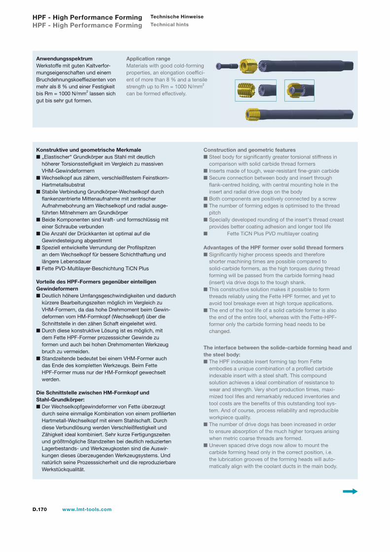
D.170 www.lmt-tools.com
HPF - High Performance Forming HPF - High Performance Forming
Technische Hinweise
Technical hints
AnwendungsspektrumWerkstoffe mit guten Kaltverfor-mungseigenschaften und einem Bruchdehnungskoeffiezienten von mehr als 8 % und einer Festigkeit bis Rm = 1000 N/mm2 lassen sich gut bis sehr gut formen.
Application rangeMaterials with good cold-forming properties, an elongation coeffici-ent of more than 8 % and a tensile strength up to Rm = 1000 N/mm2 can be formed effectively.
Konstruktive und geometrische Merkmale„Elastischer“ Grundkörper aus Stahl mit deutlich höherer Torsionssteifigkeit im Vergleich zu massiven VHM-GewindeformernWechselkopf aus zähem, verschleißfestem Feinstkorn- HartmetallsubstratStabile Verbindung Grundkörper-Wechselkopf durch flankenzentrierte Mittenaufnahme mit zentrischer Aufnahmebohrung am Wechselkopf und radial ausge- führten Mitnehmern am GrundkörperBeide Komponenten sind kraft- und formschlüssig mit einer Schraube verbundenDie Anzahl der Drückkanten ist optimal auf die Gewindesteigung abgestimmtSpeziell entwickelte Verrundung der Profilspitzen an dem Wechselkopf für bessere Schichthaftung und längere LebensdauerFette PVD-Multilayer-Beschichtung TiCN Plus
Vorteile des HPF-Formers gegenüber einteiligen Gewindeformern
Deutlich höhere Umfangsgeschwindigkeiten und dadurch kürzere Bearbeitungszeiten möglich im Vergleich zu VHM-Formern, da das hohe Drehmoment beim Gewin- deformen vom HM-Formkopf (Wechselkopf) über die Schnittstelle in den zähen Schaft eingeleitet wird.Durch diese konstruktive Lösung ist es möglich, mit dem Fette HPF-Former prozesssicher Gewinde zu formen und auch bei hohen Drehmomenten Werkzeug bruch zu vermeiden.Standzeitende bedeutet bei einem VHM-Former auch das Ende des kompletten Werkzeugs. Beim Fette HPF-Former muss nur der HM-Formkopf gewechselt werden.
Die Schnittstelle zwischen HM-Formkopf und Stahl-Grundkörper:
Der Wechselkopfgewindeformer von Fette überzeugt durch seine einmalige Kombination von einem profilierten Hartmetall-Wechselkopf mit einem Stahlschaft. Durch diese Verbundlösung werden Verschleißfestigkeit und Zähigkeit ideal kombiniert. Sehr kurze Fertigungszeiten und größtmögliche Standzeiten bei deutlich reduzierten Lagerbestands- und Werkzeugkosten sind die Auswir- kungen dieses überzeugenden Werkzeugsystems. Und natürlich seine Prozesssicherheit und die reproduzierbare Werkstückqualität.
Construction and geometric featuresSteel body for significantly greater torsional stiffness in comparison with solid carbide thread formersInserts made of tough, wear-resistant fine-grain carbide Secure connection between body and insert through flank-centred holding, with central mounting hole in the insert and radial drive dogs on the bodyBoth components are positively connected by a screwThe number of forming edges is optimised to the thread pitchSpecially developed rounding of the insert‘s thread creast provides better coating adhesion and longer tool life
Fette TiCN Plus PVD multilayer coating Advantages of the HPF former over solid thread formers
Significantly higher process speeds and therefore shorter machining times are possible compared to solid-carbide formers, as the high torques during thread forming will be passed from the carbide forming head (insert) via drive dogs to the tough shank.This constructive solution makes it possible to form threads reliably using the Fette HPF former, and yet to avoid tool breakage even at high torque applications.The end of the tool life of a solid carbide former is also the end of the entire tool, whereas with the Fette-HPF- former only the carbide forming head needs to be changed.
The interface between the solide-carbide forming head and the steel body:
The HPF indexable insert forming tap from Fette embodies a unique combination of a profiled carbide indexable insert with a steel shaft. This compound solution achieves a ideal combination of resistance to wear and strength. Very short production times, maxi- mized tool lifes and remarkably reduced inventories and tool costs are the benefits of this outstanding tool sys- tem. And of course, process reliability and reproducible workpiece quality.The number of drive dogs has been increased in order to ensure absorption of the much higher torques arising when metric coarse threads are formed.Uneven spaced drive dogs now allow to mount the carbide forming head only in the correct position, i.e. the lubrication grooves of the forming heads will auto- matically align with the coolant ducts in the main body.

D.171www.lmt-tools.com
Die Anzahl der Mitnahmestege wurde erhöht, um die viel größeren Drehmomente, die beim Formen von Regel- gewinden auftreten, sicher aufnehmen zu können.Durch eine ungleiche Teilung der Mitnahmestege ist nun nur noch eine eindeutige Positionierung des HM- Formkopfs möglich, d. h. die Schmiernuten stehen bei den IK-Versionen automatisch richtig zu den Kühlmittel- austritten am Grundkörper.Unterschiedliche baugleiche VHM-Wechselköpfe können auf ein und demselben Schaft befestigt werden – auch unter-schiedlicher GewindeartDie Schaftlänge des HPF-Gewindeformers entsprechen einer FETTE-Werknorm.
Various thread forms – which means different solid carbide indexable inserts – can now be assembled to one and the same shaft.The new shank lengths for these assebled tools are according to a Fette internal standard.
Die Schaftabmessungen wurden zudem nach dem Kriterium einer größtmöglichen Werkzeugstabilität ausgelegt.
HPF-Gewindeformer mit innerer KühlmittelzufuhrDie IK-Varianten der Grundkörper verfügen über eine nicht durch-gehende zentrale Kühlmittelbohrung und eine auf die Lage der Schmiernuten im HM-Formkopf abgestimmte Anzahl von seitlich austretenden Kühlkanälen. Diese Kühlkanäle sorgen dafür, dass das Kühlmedium optimal in die Schmiernuten des HM-Formkopfes gelangt.
The shaft dimensions have, moreover, been designed to provide the greatest possible tool stability.
HPF forming taps with internal coolant The IC body variants have a central coolant bore passing partway through the former with a number of side coolant ducts dependent on the position of the lubrication grooves in the carbide forming tap. These coolant ducts have a5 degree inclination to the axis and are open at the front, ensuring that the coolant reaches the lubrication grooves of the carbide head.
Gew
inde
n Th
read
ing
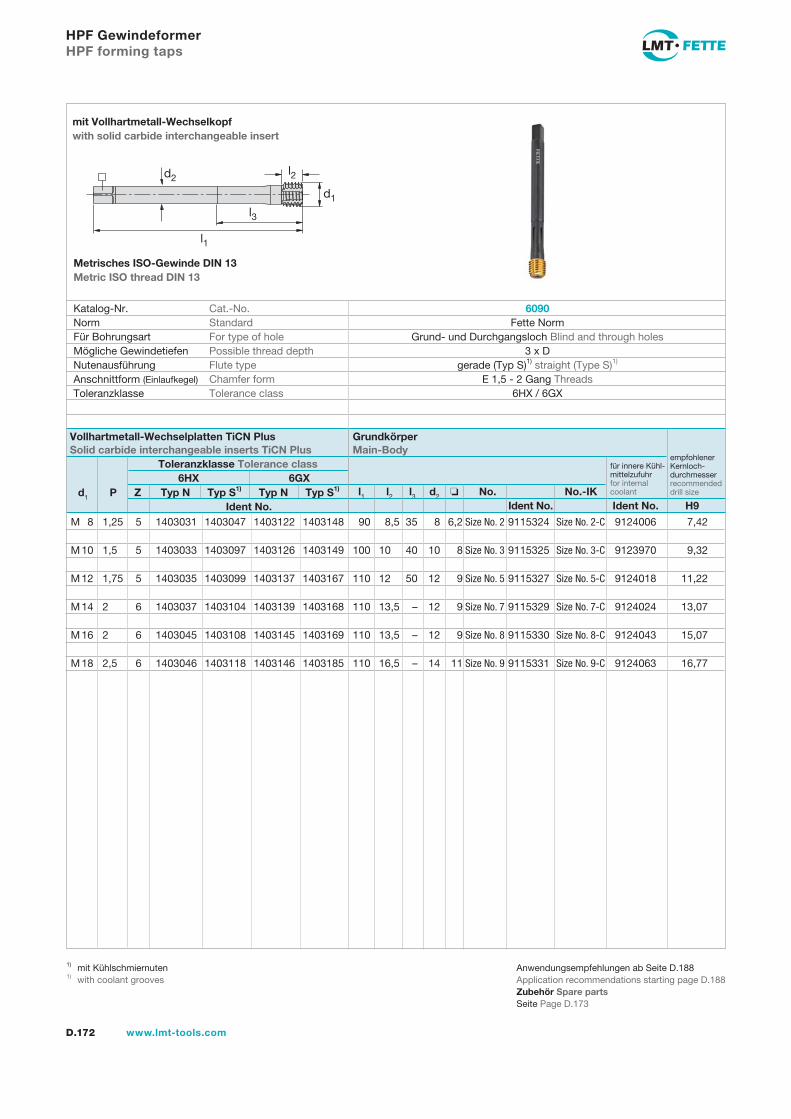
D.172 www.lmt-tools.com
HPF Gewindeformer HPF forming taps
l1 l2 l3 d2 No. No.-IK Ident No. Ident No. H9
d1 P Z Typ N Typ S1) Typ N Typ S1) Ident No.
Katalog-Nr. Cat.-No. Norm Standard Für Bohrungsart For type of hole Mögliche Gewindetiefen Possible thread depth Nutenausführung Flute type Anschnittform (Einlaufkegel) Chamfer form Toleranzklasse Tolerance class
6090 Fette Norm
Grund- und Durchgangsloch Blind and through holes 3 x D
gerade (Typ S)1) straight (Type S)1) E 1,5 - 2 Gang Threads
6HX / 6GX
mit Vollhartmetall-Wechselkopf with solid carbide interchangeable insert
Metrisches ISO-Gewinde DIN 13 Metric ISO thread DIN 13
Vollhartmetall-Wechselplatten TiCN Plus Solid carbide interchangeable inserts TiCN Plus
Grundkörper Main-Body
Toleranzklasse Tolerance class6HX 6GX
empfohlenerKernloch-durchmesser recommendeddrill size
für innere Kühl-mittelzufuhr for internal coolant
Anwendungsempfehlungen ab Seite D.188Application recommendations starting page D.188Zubehör Spare partsSeite Page D.173
M 8 1,25 5 1403031 1403047 1403122 1403148 90 8,5 35 8 6,2 Size No. 2 9115324 Size No. 2-C 9124006 7,42
M 10 1,5 5 1403033 1403097 1403126 1403149 100 10 40 10 8 Size No. 3 9115325 Size No. 3-C 9123970 9,32
M 12 1,75 5 1403035 1403099 1403137 1403167 110 12 50 12 9 Size No. 5 9115327 Size No. 5-C 9124018 11,22
M 14 2 6 1403037 1403104 1403139 1403168 110 13,5 – 12 9 Size No. 7 9115329 Size No. 7-C 9124024 13,07
M 16 2 6 1403045 1403108 1403145 1403169 110 13,5 – 12 9 Size No. 8 9115330 Size No. 8-C 9124043 15,07
M 18 2,5 6 1403046 1403118 1403146 1403185 110 16,5 – 14 11 Size No. 9 9115331 Size No. 9-C 9124063 16,77
1) mit Kühlschmiernuten1) with coolant grooves
d2
l1
l3
d1
l2
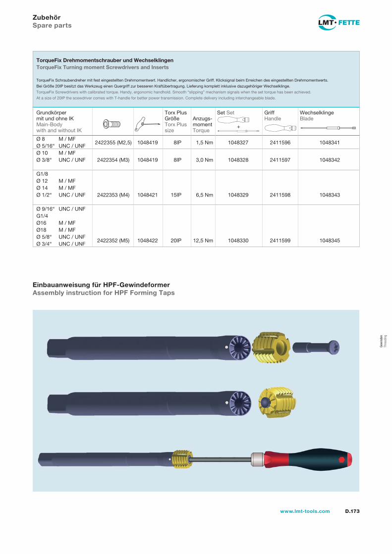
D.173www.lmt-tools.com
Zubehör Spare parts
Ø 8 M / MF 2422355 (M2,5) 1048419 8IP 1,5 Nm 1048327 2411596 1048341
Ø 5/16“ UNC / UNF Ø 10 M / MF Ø 3/8“ UNC / UNF 2422354 (M3) 1048419 8IP 3,0 Nm 1048328 2411597 1048342
G1/8 Ø 12 M / MF Ø 14 M / MF Ø 1/2“ UNC / UNF 2422353 (M4) 1048421 15IP 6,5 Nm 1048329 2411598 1048343
Ø 9/16“ UNC / UNF G1/4 Ø16 M / MF Ø18 M / MF Ø 5/8“ UNC / UNF
2422352 (M5) 1048422 20IP 12,5 Nm 1048330 2411599 1048345
Ø 3/4“ UNC / UNF
Grundkörper mit und ohne IKMain-Bodywith and without IK
Torx PlusGröße Torx Plussize
Anzugs-moment Torque
TorqueFix Drehmomentschrauber und Wechselklingen TorqueFix Turning moment Screwdrivers and Inserts
TorqueFix Schraubendreher mit fest eingestellten Drehmomentwert. Handlicher, ergonomischer Griff. Klicksignal beim Erreichen des eingestellten Drehmomentwerts.
Bei Größe 20IP besitzt das Werkzeug einen Quergriff zur besseren Kraftübertragung. Lieferung komplett inklusive dazugehöriger Wechselklinge.
TorqueFix Screwdrivers with calibrated torque. Handy, ergonomic handhold. Smooth “slipping” mechanism signals when the set torque has been achieved.
At a size of 20IP the scewdriver comes with T-handle for better power transmission. Complete delivery including interchangeable blade.
Set Set
+
Wechselklinge Blade
Griff Handle
Einbauanweisung für HPF-Gewindeformer Assembly instruction for HPF Forming Taps
Gew
inde
n Th
read
ing
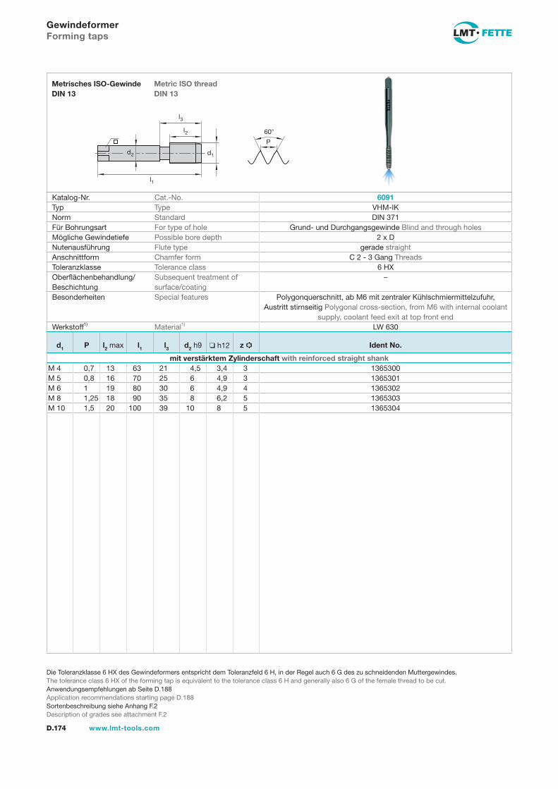
l1
d2
l2
d1
60�
P
l3
D.174 www.lmt-tools.com
Metric ISO threadDIN 13
Metrisches ISO-Gewinde DIN 13
Die Toleranzklasse 6 HX des Gewindeformers entspricht dem Toleranzfeld 6 H, in der Regel auch 6 G des zu schneidenden Muttergewindes.The tolerance class 6 HX of the forming tap is equivalent to the tolerance class 6 H and generally also 6 G of the female thread to be cut.Anwendungsempfehlungen ab Seite D.188Application recommendations starting page D.188Sortenbeschreibung siehe Anhang F.2Description of grades see attachment F.2
Gewindeformer Forming taps
Katalog-Nr. Cat.-No. 6091Typ Type VHM-IKNorm Standard DIN 371Für Bohrungsart For type of hole Grund- und Durchgangsgewinde Blind and through holesMögliche Gewindetiefe Possible bore depth 2 x DNutenausführung Flute type gerade straightAnschnittform Chamfer form C 2 - 3 Gang ThreadsToleranzklasse Tolerance class 6 HXOberflächenbehandlung/Beschichtung
Subsequent treatment ofsurface/coating
–
Besonderheiten Special features Polygonquerschnitt, ab M6 mit zentraler Kühlschmiermittelzufuhr,Austritt stirnseitig Polygonal cross-section, from M6 with internal coolant
supply, coolant feed exit at top front endWerkstoff1) Material1) LW 630
d1 P l2 max l1 l3 d2 h9 ❑ h12 z Ident No.
mit verstärktem Zylinderschaft with reinforced straight shankM 4 0,7 13 63 21 4,5 3,4 3 1365300M 5 0,8 16 70 25 6 4,9 3 1365301M 6 1 19 80 30 6 4,9 4 1365302M 8 1,25 18 90 35 8 6,2 5 1365303M 10 1,5 20 100 39 10 8 5 1365304
gew-174-177.indd 174 14.02.2008 15:46:07
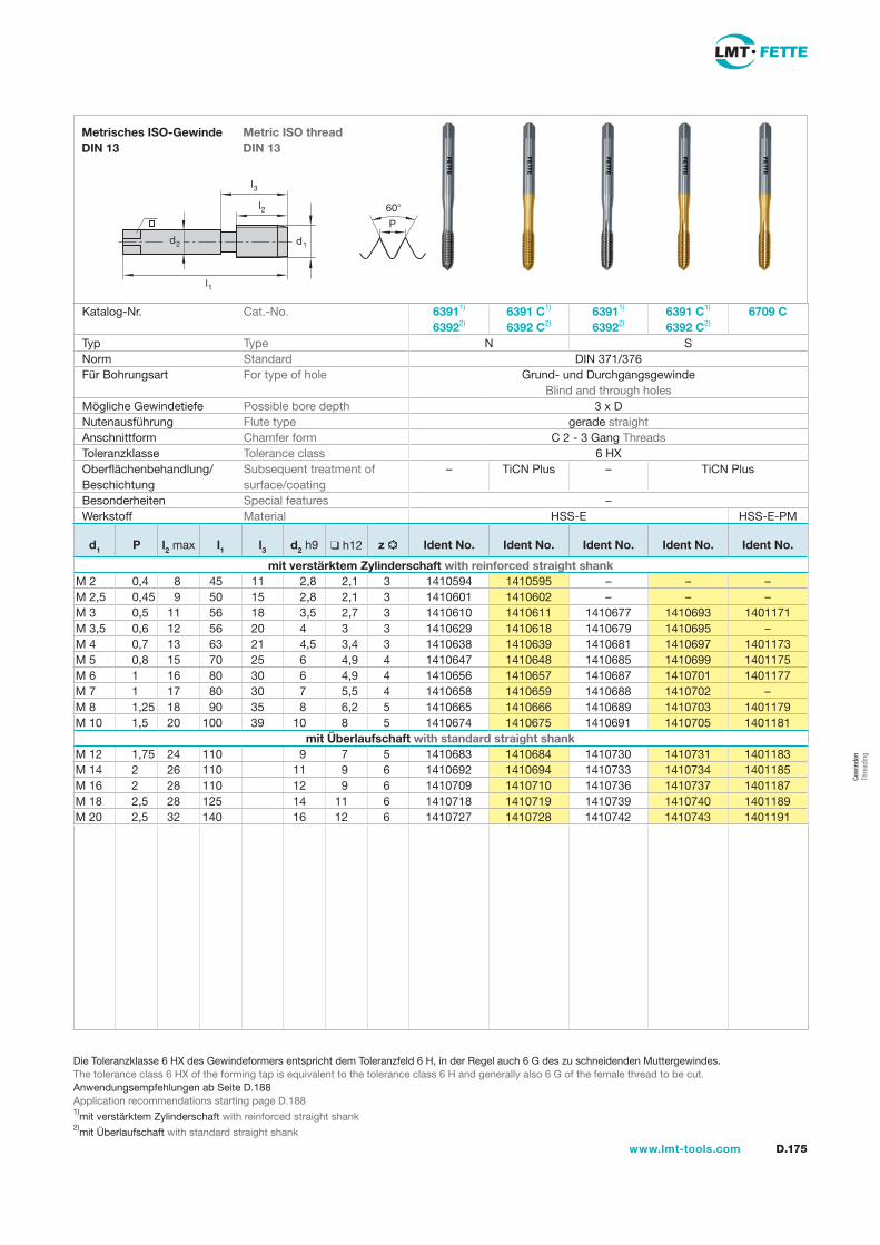
l1
d2
l2
d1
60
P
l3
D.175www.lmt-tools.com
Metric ISO thread DIN 13
Metrisches ISO-Gewinde DIN 13
Die Toleranzklasse 6 HX des Gewindeformers entspricht dem Toleranzfeld 6 H, in der Regel auch 6 G des zu schneidenden Muttergewindes.The tolerance class 6 HX of the forming tap is equivalent to the tolerance class 6 H and generally also 6 G of the female thread to be cut.Anwendungsempfehlungen ab Seite D.188Application recommendations starting page D.1881)mit verstärktem Zylinderschaft with reinforced straight shank2)mit Überlaufschaft with standard straight shank
Katalog-Nr. Cat.-No. 63911) 63922)
6391 C1)
6392 C2)63911)
63922)6391 C1) 6392 C2)
6709 C
Typ Type N SNorm Standard DIN 371/376Für Bohrungsart For type of hole Grund- und Durchgangsgewinde
Blind and through holesMögliche Gewindetiefe Possible bore depth 3 x DNutenausführung Flute type gerade straightAnschnittform Chamfer form C 2 - 3 Gang ThreadsToleranzklasse Tolerance class 6 HXOberflächenbehandlung/Beschichtung
Subsequent treatment of surface/coating
– TiCN Plus – TiCN Plus
Besonderheiten Special features –Werkstoff Material HSS-E HSS-E-PM
d1 P l2 max l1 l3 d2 h9 h12 z Ident No. Ident No. Ident No. Ident No. Ident No.
mit verstärktem Zylinderschaft with reinforced straight shankM 2 0,4 8 45 11 2,8 2,1 3 1410594 1410595 – – –M 2,5 0,45 9 50 15 2,8 2,1 3 1410601 1410602 – – –M 3 0,5 11 56 18 3,5 2,7 3 1410610 1410611 1410677 1410693 1401171M 3,5 0,6 12 56 20 4 3 3 1410629 1410618 1410679 1410695 –M 4 0,7 13 63 21 4,5 3,4 3 1410638 1410639 1410681 1410697 1401173M 5 0,8 15 70 25 6 4,9 4 1410647 1410648 1410685 1410699 1401175M 6 1 16 80 30 6 4,9 4 1410656 1410657 1410687 1410701 1401177M 7 1 17 80 30 7 5,5 4 1410658 1410659 1410688 1410702 –M 8 1,25 18 90 35 8 6,2 5 1410665 1410666 1410689 1410703 1401179M 10 1,5 20 100 39 10 8 5 1410674 1410675 1410691 1410705 1401181
mit Überlaufschaft with standard straight shankM 12 1,75 24 110 9 7 5 1410683 1410684 1410730 1410731 1401183M 14 2 26 110 11 9 6 1410692 1410694 1410733 1410734 1401185M 16 2 28 110 12 9 6 1410709 1410710 1410736 1410737 1401187M 18 2,5 28 125 14 11 6 1410718 1410719 1410739 1410740 1401189M 20 2,5 32 140 16 12 6 1410727 1410728 1410742 1410743 1401191
Gew
inde
n Th
read
ing
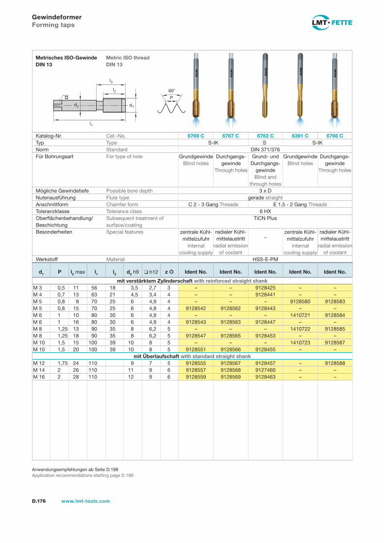
l1
d2
l2
d1
60�
P
l3
D.176 www.lmt-tools.com
Metric ISO threadDIN 13
Metrisches ISO-Gewinde DIN 13
Anwendungsempfehlungen ab Seite D.188Application recommendations starting page D.188
Gewindeformer Forming taps
Katalog-Nr. Cat.-No. 6769 C 6767 C 6762 C 6391 C 6766 CTyp Type S-IK S S-IKNorm Standard DIN 371/376Für Bohrungsart For type of hole
Mögliche Gewindetiefe Possible bore depth 3 x DNutenausführung Flute type gerade straightAnschnittform Chamfer form C 2 - 3 Gang Threads E 1,5 - 2 Gang ThreadsToleranzklasse Tolerance class 6 HXOberflächenbehandlung/Beschichtung
Subsequent treatment ofsurface/coating
TiCN Plus
Besonderheiten Special features
Werkstoff Material HSS-E-PM
GrundgewindeBlind holes
Grund- undDurchgangs-
gewindeBlind and
through holes
zentrale Kühl-mittelzufuhr
internalcooling supply
radialer Kühl-mittelaustritt
radial emissionof coolant
–zentrale Kühl-mittelzufuhr
internalcooling supply
radialer Kühl-mittelaustritt
radial emissionof coolant
Durchgangs-gewinde
Through holes
GrundgewindeBlind holes
Durchgangs-gewinde
Through holes
d1 P l2 max l1 l3 d2 h9 ❑ h12 z Ident No. Ident No. Ident No. Ident No. Ident No.
mit verstärktem Zylinderschaft with reinforced straight shankM 3 0,5 11 56 18 3,5 2,7 3 – – 9128425 – –M 4 0,7 13 63 21 4,5 3,4 4 – – 9128441 – –M 5 0,8 8 70 25 6 4,9 4 – – – 9128580 9128583M 5 0,8 15 70 25 6 4,9 4 9128542 9128562 9128443 – –M 6 1 10 80 30 6 4,9 4 – – – 1410721 9128584M 6 1 16 80 30 6 4,9 4 9128543 9128563 9128447 – –M 8 1,25 13 90 35 8 6,2 5 – – – 1410722 9128585M 8 1,25 18 90 35 8 6,2 5 9128547 9128565 9128453 – –M 10 1,5 15 100 39 10 8 5 – – – 1410723 9128587M 10 1,5 20 100 39 10 8 5 9128551 9128566 9128455 – –
mit Überlaufschaft with standard straight shankM 12 1,75 24 110 9 7 5 9128555 9128567 9128457 – 9128588M 14 2 26 110 11 9 6 9128557 9128568 9127460 – –M 16 2 28 110 12 9 6 9128559 9128569 9128463 – –
gew-174-177.indd 176 25.02.2008 12:05:08
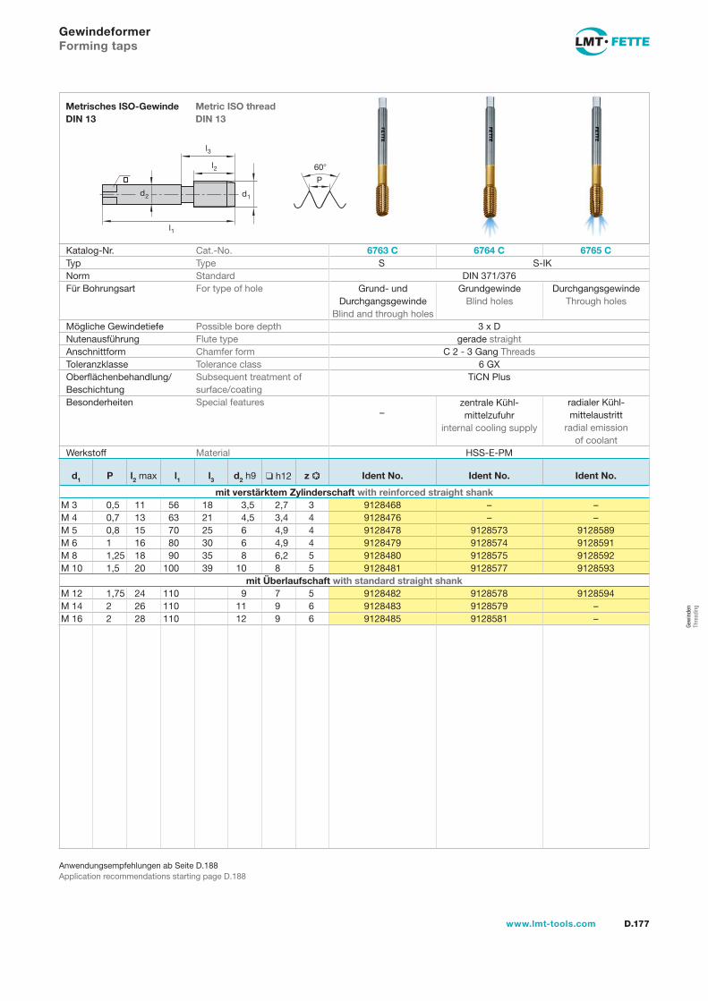
l1
d2
l2
d1
60�
P
l3
D.177www.lmt-tools.com
Metric ISO threadDIN 13
Metrisches ISO-Gewinde DIN 13
Anwendungsempfehlungen ab Seite D.188Application recommendations starting page D.188
Gewindeformer Forming taps
Katalog-Nr. Cat.-No. 6763 C 6764 C 6765 CTyp Type S S-IKNorm Standard DIN 371/376Für Bohrungsart For type of hole
Mögliche Gewindetiefe Possible bore depth 3 x DNutenausführung Flute type gerade straightAnschnittform Chamfer form C 2 - 3 Gang ThreadsToleranzklasse Tolerance class 6 GXOberflächenbehandlung/Beschichtung
Subsequent treatment ofsurface/coating
TiCN Plus
Besonderheiten Special features
Werkstoff Material HSS-E-PM
Grund- undDurchgangsgewinde
Blind and through holes
zentrale Kühl-mittelzufuhr
internal cooling supply
radialer Kühl-mittelaustritt
radial emissionof coolant
–
GrundgewindeBlind holes
DurchgangsgewindeThrough holes
d1 P l2 max l1 l3 d2 h9 ❑ h12 z Ident No. Ident No. Ident No.
mit verstärktem Zylinderschaft with reinforced straight shankM 3 0,5 11 56 18 3,5 2,7 3 9128468 – –M 4 0,7 13 63 21 4,5 3,4 4 9128476 – –M 5 0,8 15 70 25 6 4,9 4 9128478 9128573 9128589M 6 1 16 80 30 6 4,9 4 9128479 9128574 9128591M 8 1,25 18 90 35 8 6,2 5 9128480 9128575 9128592M 10 1,5 20 100 39 10 8 5 9128481 9128577 9128593
mit Überlaufschaft with standard straight shankM 12 1,75 24 110 9 7 5 9128482 9128578 9128594M 14 2 26 110 11 9 6 9128483 9128579 –M 16 2 28 110 12 9 6 9128485 9128581 –
Gew
inde
nTh
read
ing
gew-174-177.indd 177 25.02.2008 12:05:11
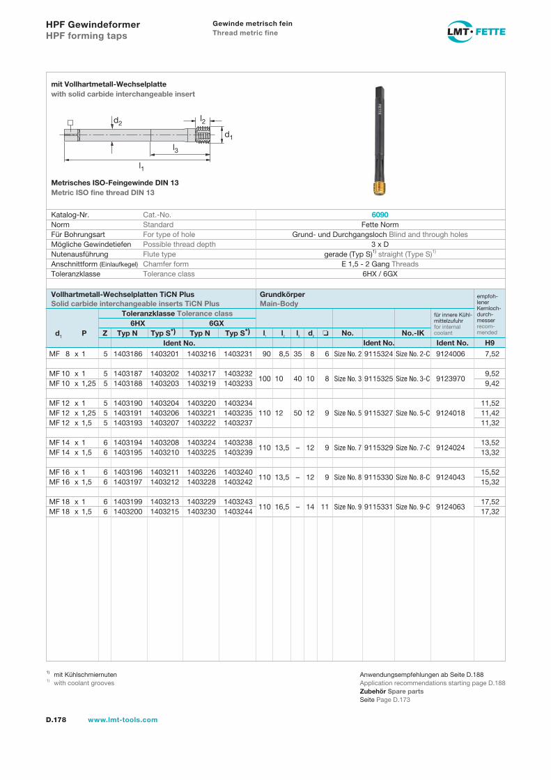
D.178 www.lmt-tools.com
l1 l2 l3 d2 No. No.-IK Ident No. Ident No. H9
d1 P Z Typ N Typ S*) Typ N Typ S*) Ident No.
Vollhartmetall-Wechselplatten TiCN Plus Solid carbide interchangeable inserts TiCN Plus
Grundkörper Main-Body
Toleranzklasse Tolerance class6HX 6GX
empfoh-lener Kernloch-durch-messer recom-mended
für innere Kühl-mittelzufuhr for internal coolant
MF 8 x 1 5 1403186 1403201 1403216 1403231 90 8,5 35 8 6 Size No. 2 9115324 Size No. 2-C 9124006 7,52 MF 10 x 1 5 1403187 1403202 1403217 1403232
100 10 40 10 8 Size No. 3 9115325 Size No. 3-C 9123970 9,52
MF 10 x 1,25 5 1403188 1403203 1403219 1403233 9,42 MF 12 x 1 5 1403190 1403204 1403220 1403234
11,52
MF 12 x 1,25 5 1403191 1403206 1403221 1403235 110 12 50 12 9 Size No. 5 9115327 Size No. 5-C 9124018 11,42 MF 12 x 1,5 5 1403193 1403207 1403222 1403237 11,32 MF 14 x 1 6 1403194 1403208 1403224 1403238
110 13,5 – 12 9 Size No. 7 9115329 Size No. 7-C 9124024 13,52
MF 14 x 1,5 6 1403195 1403210 1403225 1403239 13,32 MF 16 x 1 6 1403196 1403211 1403226 1403240
110 13,5 – 12 9 Size No. 8 9115330 Size No. 8-C 9124043 15,52
MF 16 x 1,5 6 1403197 1403212 1403228 1403242 15,32 MF 18 x 1 6 1403199 1403213 1403229 1403243
110 16,5 – 14 11 Size No. 9 9115331 Size No. 9-C 9124063 17,52
MF 18 x 1,5 6 1403200 1403215 1403230 1403244 17,32
HPF Gewindeformer HPF forming taps
Anwendungsempfehlungen ab Seite D.188Application recommendations starting page D.188Zubehör Spare partsSeite Page D.173
1) mit Kühlschmiernuten1) with coolant grooves
Katalog-Nr. Cat.-No. Norm Standard Für Bohrungsart For type of hole Mögliche Gewindetiefen Possible thread depth Nutenausführung Flute type Anschnittform (Einlaufkegel) Chamfer form Toleranzklasse Tolerance class
6090 Fette Norm
Grund- und Durchgangsloch Blind and through holes 3 x D
gerade (Typ S)1) straight (Type S)1) E 1,5 - 2 Gang Threads
6HX / 6GX
mit Vollhartmetall-Wechselplatte with solid carbide interchangeable insert
Metrisches ISO-Feingewinde DIN 13 Metric ISO fine thread DIN 13
d2
l1
l3
d1
l2
Gewinde metrisch fein Thread metric fine
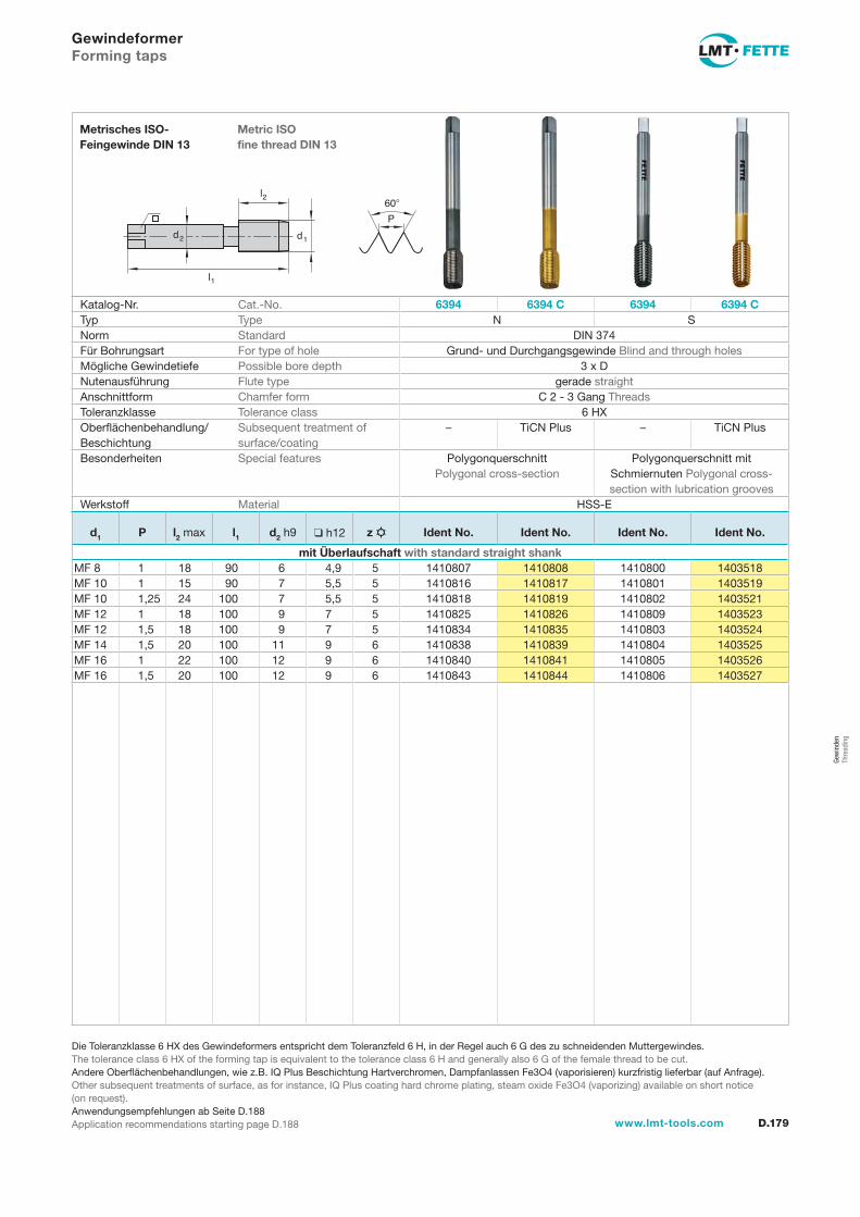
l1
d2
l2
d1
60
P
D.179www.lmt-tools.com
Metric ISO fine thread DIN 13
Metrisches ISO- Feingewinde DIN 13
Die Toleranzklasse 6 HX des Gewindeformers entspricht dem Toleranzfeld 6 H, in der Regel auch 6 G des zu schneidenden Muttergewindes.The tolerance class 6 HX of the forming tap is equivalent to the tolerance class 6 H and generally also 6 G of the female thread to be cut.Andere Oberflächenbehandlungen, wie z.B. IQ Plus Beschichtung Hartverchromen, Dampfanlassen Fe3O4 (vaporisieren) kurzfristig lieferbar (auf Anfrage).Other subsequent treatments of surface, as for instance, IQ Plus coating hard chrome plating, steam oxide Fe3O4 (vaporizing) available on short notice (on request).Anwendungsempfehlungen ab Seite D.188Application recommendations starting page D.188
GewindeformerForming taps
Katalog-Nr. Cat.-No. 6394 6394 C 6394 6394 CTyp Type N SNorm Standard DIN 374Für Bohrungsart For type of hole Grund- und Durchgangsgewinde Blind and through holesMögliche Gewindetiefe Possible bore depth 3 x DNutenausführung Flute type gerade straightAnschnittform Chamfer form C 2 - 3 Gang ThreadsToleranzklasse Tolerance class 6 HXOberflächenbehandlung/Beschichtung
Subsequent treatment of surface/coating
– TiCN Plus – TiCN Plus
Besonderheiten Special features Polygonquerschnitt Polygonal cross-section
Polygonquerschnitt mit Schmiernuten Polygonal cross- section with lubrication grooves
Werkstoff Material HSS-E
d1 P l2 max l1 d2 h9 h12 z Ident No. Ident No. Ident No. Ident No.
mit Überlaufschaft with standard straight shankMF 8 1 18 90 6 4,9 5 1410807 1410808 1410800 1403518MF 10 1 15 90 7 5,5 5 1410816 1410817 1410801 1403519MF 10 1,25 24 100 7 5,5 5 1410818 1410819 1410802 1403521MF 12 1 18 100 9 7 5 1410825 1410826 1410809 1403523MF 12 1,5 18 100 9 7 5 1410834 1410835 1410803 1403524MF 14 1,5 20 100 11 9 6 1410838 1410839 1410804 1403525MF 16 1 22 100 12 9 6 1410840 1410841 1410805 1403526MF 16 1,5 20 100 12 9 6 1410843 1410844 1410806 1403527
Gew
inde
n Th
read
ing
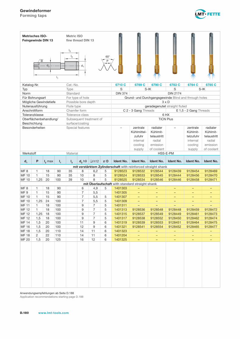
l1
d2
l2
d1
60
P
l3
D.180 www.lmt-tools.com
Metric ISO fine thread DIN 13
Metrisches ISO- Feingewinde DIN 13
Anwendungsempfehlungen ab Seite D.188Application recommendations starting page D.188
GewindeformerForming taps
Katalog-Nr. Cat.-No. 6710 C 6789 C 6790 C 6783 C 6784 C 6785 CTyp Type S S-IK S S-IKNorm Standard DIN 374 DIN 2174Für Bohrungsart For type of hole Grund- und Durchgangsgewinde Blind and through holesMögliche Gewindetiefe Possible bore depth 3 x DNutenausführung Flute type geradegenutet straight flutedAnschnittform Chamfer form C 2 - 3 Gang Threads E 1,5 - 2 Gang ThreadsToleranzklasse Tolerance class 6 HXOberflächenbehandlung/Beschichtung
Subsequent treatment of surface/coating
TiCN Plus
Besonderheiten Special features – radialer Kühlmit-telaustritt
radial emissionof coolant
– zentrale Kühlmit-telzufuhr internal cooling supply
radialer Kühlmit-telaustritt
radial emissionof coolant
Werkstoff Material HSS-E-PM
zentrale Kühlmittel-
zufuhr internal cooling supply
d1 P l2 max l1 l3 d2 h9 h12 z Ident No. Ident No. Ident No. Ident No. Ident No. Ident No.
mit verstärktem Zylinderschaft with reinforced straight shankMF 8 1 18 90 35 8 6,2 5 9128523 9128532 9128544 9128439 9128454 9128469MF 10 1 15 90 35 10 8 5 9128524 9128533 9128545 9128444 9128456 9128470MF 10 1,25 20 100 39 10 8 5 9128525 9128534 9128546 9128446 9128458 9128471
mit Überlaufschaft with standard straight shankMF 8 1 18 90 6 4,9 5 1401303 – – – – –MF 9 1 15 90 7 5,5 1401305 – – – – –MF 10 1 15 90 7 5,5 5 1401307 – – – – –MF 10 1,25 24 100 7 5,5 5 1401309 – – – – –MF 11 1 18 100 9 7 5 1401311 – – – – –MF 12 1 18 100 9 7 5 1401313 9128536 9128548 9128448 9128459 9128472MF 12 1,25 18 100 9 7 5 1401315 9128537 9128549 9128449 9128461 9128473MF 12 1,5 18 100 9 7 5 1401317 9128538 9128552 9128450 9128462 9128474MF 14 1,5 20 100 11 9 6 1401319 9128539 9128553 9128451 9128464 9128475MF 16 1,5 20 100 12 9 6 1401321 9128541 9128554 9128452 9128465 9128477MF 18 1,5 20 110 14 11 6 1401323 – – – – –MF 18 2 22 110 14 11 6 1401204 – – – – –MF 20 1,5 20 125 16 12 6 1401325 – – – – –
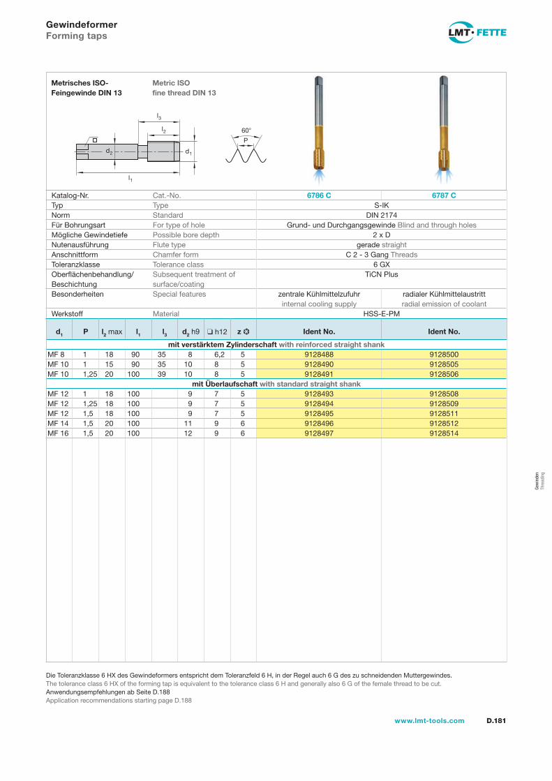
l1
d2
l2
d1
60
P
l3
D.181www.lmt-tools.com
Metric ISO fine thread DIN 13
Metrisches ISO- Feingewinde DIN 13
Die Toleranzklasse 6 HX des Gewindeformers entspricht dem Toleranzfeld 6 H, in der Regel auch 6 G des zu schneidenden Muttergewindes.The tolerance class 6 HX of the forming tap is equivalent to the tolerance class 6 H and generally also 6 G of the female thread to be cut.Anwendungsempfehlungen ab Seite D.188Application recommendations starting page D.188
GewindeformerForming taps
Katalog-Nr. Cat.-No. 6786 C 6787 CTyp Type S-IKNorm Standard DIN 2174Für Bohrungsart For type of hole Grund- und Durchgangsgewinde Blind and through holesMögliche Gewindetiefe Possible bore depth 2 x DNutenausführung Flute type gerade straightAnschnittform Chamfer form C 2 - 3 Gang ThreadsToleranzklasse Tolerance class 6 GXOberflächenbehandlung/Beschichtung
Subsequent treatment of surface/coating
TiCN Plus
Besonderheiten Special features zentrale Kühlmittelzufuhrinternal cooling supply
radialer Kühlmittelaustrittradial emission of coolant
Werkstoff Material HSS-E-PM
d1 P l2 max l1 l3 d2 h9 h12 z Ident No. Ident No.
mit verstärktem Zylinderschaft with reinforced straight shankMF 8 1 18 90 35 8 6,2 5 9128488 9128500MF 10 1 15 90 35 10 8 5 9128490 9128505MF 10 1,25 20 100 39 10 8 5 9128491 9128506
mit Überlaufschaft with standard straight shankMF 12 1 18 100 9 7 5 9128493 9128508MF 12 1,25 18 100 9 7 5 9128494 9128509MF 12 1,5 18 100 9 7 5 9128495 9128511MF 14 1,5 20 100 11 9 6 9128496 9128512MF 16 1,5 20 100 12 9 6 9128497 9128514
Gew
inde
n Th
read
ing

D.182 www.lmt-tools.com
HPF Gewindeformer HPF forming taps
Katalog-Nr. Cat.-No. Norm Standard Für Bohrungsart For type of hole Mögliche Gewindetiefen Possible thread depth Nutenausführung Flute type Anschnittform (Einlaufkegel) Chamfer form Toleranzklasse Tolerance class
mit Vollhartmetall-Wechselkopf with solid carbide interchangeable insert
UNC GewindeUNC thread
l1 l2 l3 d2 No. No.-IK Ident No. Ident No. H9
d1 P Z Typ N Typ S1) Ident No.
Vollhartmetall-Wechselplatten TiCN Plus Solid carbide interchangeable inserts TiCN Plus
Grundkörper Main-Body
Toleranzklasse Tolerance classNennmaß Nominal
Size2BX
empfohlenerKernloch-durchmesser recommendeddrill size
für innere Kühl-mittelzufuhr for internal coolant
6080 Fette Norm
Grund- und Durchgangsloch Blind and through holes 3 x D
gerade (Typ S)1) straight (Type S)1) E 1,5 - 2 Gang Threads
2BX
UNC Gewinde (grob) ASME-B1.1UNC thread (coarse) ASME-B1.1
Anwendungsempfehlungen ab Seite D.188Application recommendations starting page D.188Zubehör Spare partsSeite Page D.173
1) mit Kühlschmiernuten1) with coolant grooves
d2
l1
l3
d1
l2
UNC 5/16 7,938 18 5 1403256 1403264 90 8,5 35 8 6,2 Size No. 2 9115324 Size No. 2-C 9124006 7,23 UNC 3/8 9,525 16 5 1403257 1403265 100 10 40 10 8 Size No. 3 9115325 Size No. 3-C 9123970 8,73 UNC 7/16 11,113 14 5 1403258 1403266 100 12 45 11 9 Size No. 4 9115326 Size No. 4-C 9126424 10,20 UNC 1/2 12,7 13 5 1403259 1403267 110 13 50 12 9 Size No. 6 9115328 Size No. 6-C 9126425 11,72 UNC 9/16 14,288 12 6 1403260 1403268 110 13,5 – 12 9 Size No. 7 9115329 Size No. 7-C 9124024 13,22 UNC 5/8 15,875 11 6 1403261 1403270 110 13,5 – 12 9 Size No. 8 9115330 Size No. 8-C 9124043 14,72 UNC 3/4 19,05 10 7 1403262 1403271 125 16,5 – 16 12 Size No. 10 9115332 Size No. 10-C 9126426 17,77
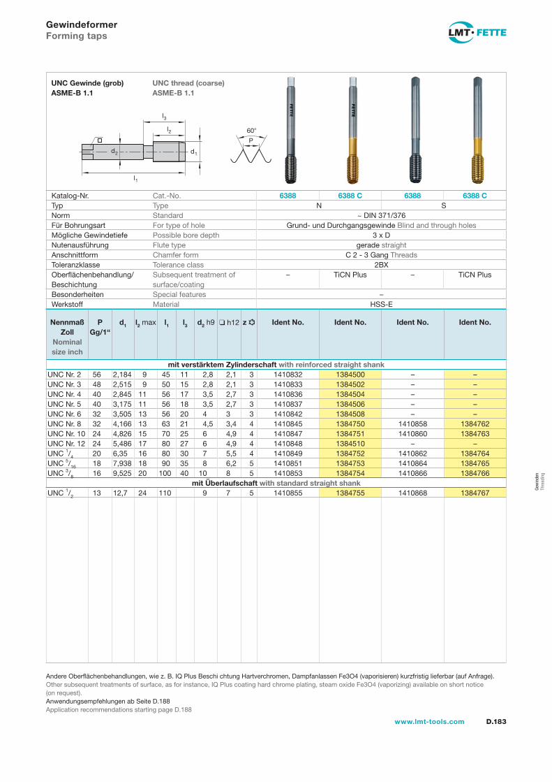
l1
d2
l2
d1
60�
P
l3
D.183www.lmt-tools.com
UNC thread (coarse) ASME-B 1.1
UNC Gewinde (grob) ASME-B 1.1
Andere Oberflächenbehandlungen, wie z. B. IQ Plus Beschi chtung Hartverchromen, Dampfanlassen Fe3O4 (vaporisieren) kurzfristig lieferbar (auf Anfrage).Other subsequent treatments of surface, as for instance, IQ Plus coating hard chrome plating, steam oxide Fe3O4 (vaporizing) available on short notice(on request).Anwendungsempfehlungen ab Seite D.188Application recommendations starting page D.188
Gewindeformer Forming taps
Katalog-Nr. Cat.-No. 6388 6388 C 6388 6388 CTyp Type N SNorm Standard ~ DIN 371/376Für Bohrungsart For type of hole Grund- und Durchgangsgewinde Blind and through holesMögliche Gewindetiefe Possible bore depth 3 x DNutenausführung Flute type gerade straightAnschnittform Chamfer form C 2 - 3 Gang ThreadsToleranzklasse Tolerance class 2BXOberflächenbehandlung/Beschichtung
Subsequent treatment ofsurface/coating
– TiCN Plus – TiCN Plus
Besonderheiten Special features –Werkstoff Material HSS-E
Nennmaß Zoll
Nominal size inch
PGg/1“
d1 l2 max l1 l3 d2 h9 ❑ h12 z Ident No. Ident No. Ident No. Ident No.
mit verstärktem Zylinderschaft with reinforced straight shankUNC Nr. 2 56 2,184 9 45 11 2,8 2,1 3 1410832 1384500 – –UNC Nr. 3 48 2,515 9 50 15 2,8 2,1 3 1410833 1384502 – –UNC Nr. 4 40 2,845 11 56 17 3,5 2,7 3 1410836 1384504 – –UNC Nr. 5 40 3,175 11 56 18 3,5 2,7 3 1410837 1384506 – –UNC Nr. 6 32 3,505 13 56 20 4 3 3 1410842 1384508 – –UNC Nr. 8 32 4,166 13 63 21 4,5 3,4 4 1410845 1384750 1410858 1384762UNC Nr. 10 24 4,826 15 70 25 6 4,9 4 1410847 1384751 1410860 1384763UNC Nr. 12 24 5,486 17 80 27 6 4,9 4 1410848 1384510 – –UNC 1/4 20 6,35 16 80 30 7 5,5 4 1410849 1384752 1410862 1384764UNC 5/16 18 7,938 18 90 35 8 6,2 5 1410851 1384753 1410864 1384765UNC 3/8 16 9,525 20 100 40 10 8 5 1410853 1384754 1410866 1384766
mit Überlaufschaft with standard straight shankUNC 1/2 13 12,7 24 110 9 7 5 1410855 1384755 1410868 1384767
Gew
inde
nTh
read
ing
gew-183.indd 183 14.02.2008 15:48:03
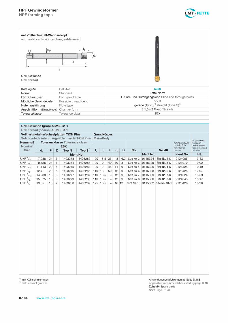
D.184 www.lmt-tools.com
HPF Gewindeformer HPF forming taps
Katalog-Nr. Cat.-No. Norm Standard Für Bohrungsart For type of hole Mögliche Gewindetiefen Possible thread depth Nutenausführung Flute type Anschnittform (Einlaufkegel) Chamfer form Toleranzklasse Tolerance class
mit Vollhartmetall-Wechselkopf with solid carbide interchangeable insert
UNF GewindeUNF thread
l1 l2 l3 d2 No. No.-IK Ident No. Ident No. H9
d1 P Z Typ N Typ S1) Ident No.
Vollhartmetall-Wechselplatten TiCN Plus Solid carbide interchangeable inserts TiCN Plus
Grundkörper Main-Body
Toleranzklasse Tolerance classNennmaß Nominal
Size2BX
empfohlenerKernloch-durchmesser recommendeddrill size
für innere Kühl-mittelzufuhr for internal coolant
6080 Fette Norm
Grund- und Durchgangsloch Blind and through holes 3 x D
gerade (Typ S)1) straight (Type S)1) E 1,5 - 2 Gang Threads
2BX
UNF Gewinde (grob) ASME-B1.1UNF thread (coarse) ASME-B1.1
Anwendungsempfehlungen ab Seite D.188Application recommendations starting page D.188Zubehör Spare partsSeite Page D.173
1) mit Kühlschmiernuten1) with coolant grooves
d2
l1
l3
d1
l2
UNF 5/16 7,938 24 5 1403273 1403282 90 8,5 35 8 6,2 Size No. 2 9115324 Size No. 2-C 9124006 7,43 UNF 3/8 9,525 24 5 1403274 1403283 100 10 40 10 8 Size No. 3 9115325 Size No. 3-C 9123970 9,02 UNF 7/16 11,113 20 5 1403275 1403284 100 12 45 11 9 Size No. 4 9115326 Size No. 4-C 9126424 10,49 UNF 1/2 12,7 20 5 1403276 1403285 110 13 50 12 9 Size No. 6 9115328 Size No. 6-C 9126425 12,07 UNF 9/16 14,288 18 6 1403277 1403287 110 13,5 – 12 9 Size No. 7 9115329 Size No. 7-C 9124024 13,59 UNF 5/8 15,875 18 6 1403279 1403288 110 13,5 – 12 9 Size No. 8 9115330 Size No. 8-C 9124043 15,17 UNF 3/4 19,05 16 7 1403280 1403289 125 16,5 – 16 12 Size No. 10 9115332 Size No. 10-C 9126426 18,26
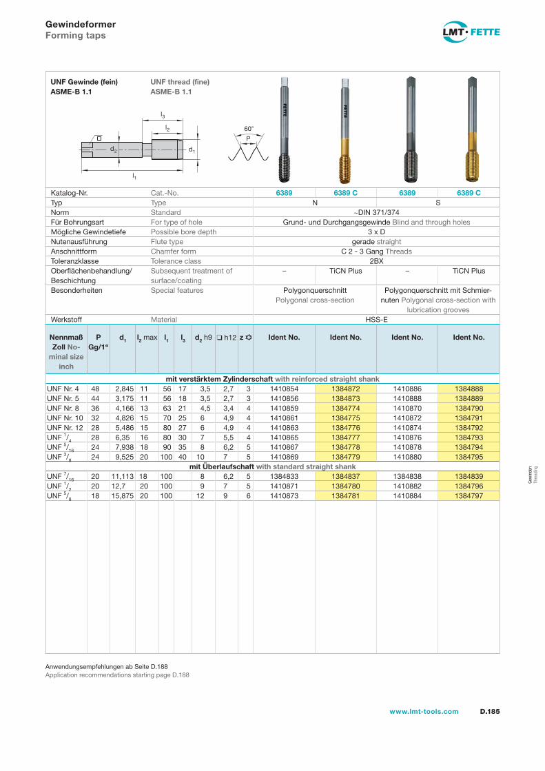
l1
d2
l2
d1
60
P
l3
D.185www.lmt-tools.com
UNF thread (fine) ASME-B 1.1
UNF Gewinde (fein) ASME-B 1.1
Anwendungsempfehlungen ab Seite D.188Application recommendations starting page D.188
GewindeformerForming taps
Katalog-Nr. Cat.-No. 6389 6389 C 6389 6389 CTyp Type N SNorm Standard ~DIN 371/374Für Bohrungsart For type of hole Grund- und Durchgangsgewinde Blind and through holesMögliche Gewindetiefe Possible bore depth 3 x DNutenausführung Flute type gerade straightAnschnittform Chamfer form C 2 - 3 Gang ThreadsToleranzklasse Tolerance class 2BXOberflächenbehandlung/Beschichtung
Subsequent treatment of surface/coating
– TiCN Plus – TiCN Plus
Besonderheiten Special features Polygonquerschnitt Polygonal cross-section
Polygonquerschnitt mit Schmier-nuten Polygonal cross-section with
lubrication groovesWerkstoff Material HSS-E
Nennmaß Zoll No-
minal size inch
PGg/1“
d1 l2 max l1 l3 d2 h9 h12 z Ident No. Ident No. Ident No. Ident No.
mit verstärktem Zylinderschaft with reinforced straight shankUNF Nr. 4 48 2,845 11 56 17 3,5 2,7 3 1410854 1384872 1410886 1384888UNF Nr. 5 44 3,175 11 56 18 3,5 2,7 3 1410856 1384873 1410888 1384889UNF Nr. 8 36 4,166 13 63 21 4,5 3,4 4 1410859 1384774 1410870 1384790UNF Nr. 10 32 4,826 15 70 25 6 4,9 4 1410861 1384775 1410872 1384791UNF Nr. 12 28 5,486 15 80 27 6 4,9 4 1410863 1384776 1410874 1384792UNF 1/4 28 6,35 16 80 30 7 5,5 4 1410865 1384777 1410876 1384793UNF 5/16 24 7,938 18 90 35 8 6,2 5 1410867 1384778 1410878 1384794UNF 3/8 24 9,525 20 100 40 10 7 5 1410869 1384779 1410880 1384795
mit Überlaufschaft with standard straight shankUNF 7/16 20 11,113 18 100 8 6,2 5 1384833 1384837 1384838 1384839UNF 1/2 20 12,7 20 100 9 7 5 1410871 1384780 1410882 1384796UNF 5/8 18 15,875 20 100 12 9 6 1410873 1384781 1410884 1384797
Gew
inde
n Th
read
ing
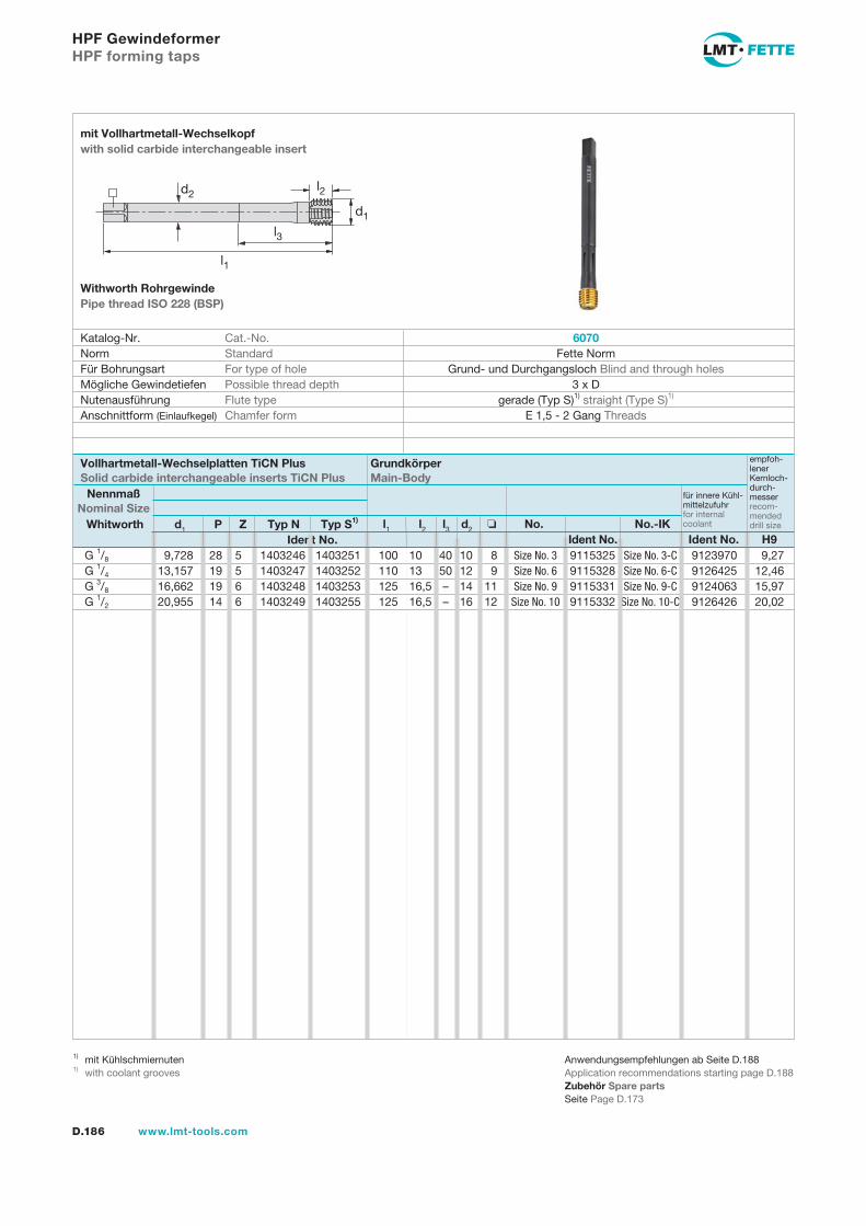
D.186 www.lmt-tools.com
HPF Gewindeformer HPF forming taps
Anwendungsempfehlungen ab Seite D.188Application recommendations starting page D.188Zubehör Spare partsSeite Page D.173
1) mit Kühlschmiernuten1) with coolant grooves
l1 l2 l3 d2 No. No.-IK Ident No. Ident No. H9
Whitworth d1 P Z Typ N Typ S1) Ident No.
Katalog-Nr. Cat.-No. Norm Standard Für Bohrungsart For type of hole Mögliche Gewindetiefen Possible thread depth Nutenausführung Flute type Anschnittform (Einlaufkegel) Chamfer form
mit Vollhartmetall-Wechselkopf with solid carbide interchangeable insert
Withworth Rohrgewinde Pipe thread ISO 228 (BSP)
Vollhartmetall-Wechselplatten TiCN Plus Solid carbide interchangeable inserts TiCN Plus
Grundkörper Main-Body
Nennmaß Nominal Size
G 1/8 9,728 28 5 1403246 1403251 100 10 40 10 8 Size No. 3 9115325 Size No. 3-C 9123970 9,27 G 1/4 13,157 19 5 1403247 1403252 110 13 50 12 9 Size No. 6 9115328 Size No. 6-C 9126425 12,46 G 3/8 16,662 19 6 1403248 1403253 125 16,5 – 14 11 Size No. 9 9115331 Size No. 9-C 9124063 15,97 G 1/2 20,955 14 6 1403249 1403255 125 16,5 – 16 12 Size No. 10 9115332 Size No. 10-C 9126426 20,02
empfoh-lener Kernloch-durch-messer recom-mendeddrill size
für innere Kühl-mittelzufuhr for internal coolant
d2
l1
l3
d1
l2
6070Fette Norm
Grund- und Durchgangsloch Blind and through holes 3 x D
gerade (Typ S)1) straight (Type S)1) E 1,5 - 2 Gang Threads
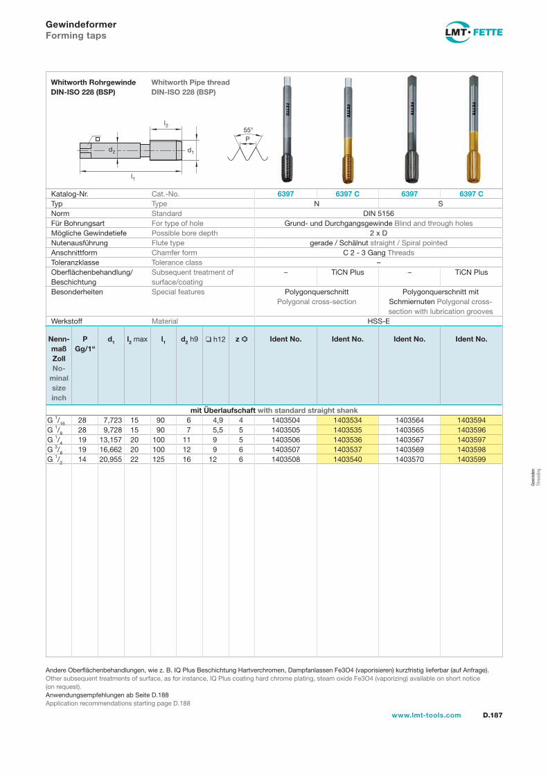
l1
d2
l2
d1
55P
D.187www.lmt-tools.com
Whitworth Pipe thread DIN-ISO 228 (BSP)
Whitworth Rohrgewinde DIN-ISO 228 (BSP)
Andere Oberflächenbehandlungen, wie z. B. IQ Plus Beschichtung Hartverchromen, Dampfanlassen Fe3O4 (vaporisieren) kurzfristig lieferbar (auf Anfrage).Other subsequent treatments of surface, as for instance, IQ Plus coating hard chrome plating, steam oxide Fe3O4 (vaporizing) available on short notice (on request).Anwendungsempfehlungen ab Seite D.188Application recommendations starting page D.188
GewindeformerForming taps
Katalog-Nr. Cat.-No. 6397 6397 C 6397 6397 CTyp Type N SNorm Standard DIN 5156Für Bohrungsart For type of hole Grund- und Durchgangsgewinde Blind and through holesMögliche Gewindetiefe Possible bore depth 2 x DNutenausführung Flute type gerade / Schälnut straight / Spiral pointedAnschnittform Chamfer form C 2 - 3 Gang ThreadsToleranzklasse Tolerance class –Oberflächenbehandlung/Beschichtung
Subsequent treatment of surface/coating
– TiCN Plus – TiCN Plus
Besonderheiten Special features Polygonquerschnitt Polygonal cross-section
Polygonquerschnitt mit Schmiernuten Polygonal cross- section with lubrication grooves
Werkstoff Material HSS-E
Nenn-maß Zoll No-
minal size inch
PGg/1“
d1 l2 max l1 d2 h9 h12 z Ident No. Ident No. Ident No. Ident No.
mit Überlaufschaft with standard straight shankG 1/16 28 7,723 15 90 6 4,9 4 1403504 1403534 1403564 1403594G 1/8 28 9,728 15 90 7 5,5 5 1403505 1403535 1403565 1403596G 1/4 19 13,157 20 100 11 9 5 1403506 1403536 1403567 1403597G 3/8 19 16,662 20 100 12 9 6 1403507 1403537 1403569 1403598G 1/2 14 20,955 22 125 16 12 6 1403508 1403540 1403570 1403599
Gew
inde
n Th
read
ing
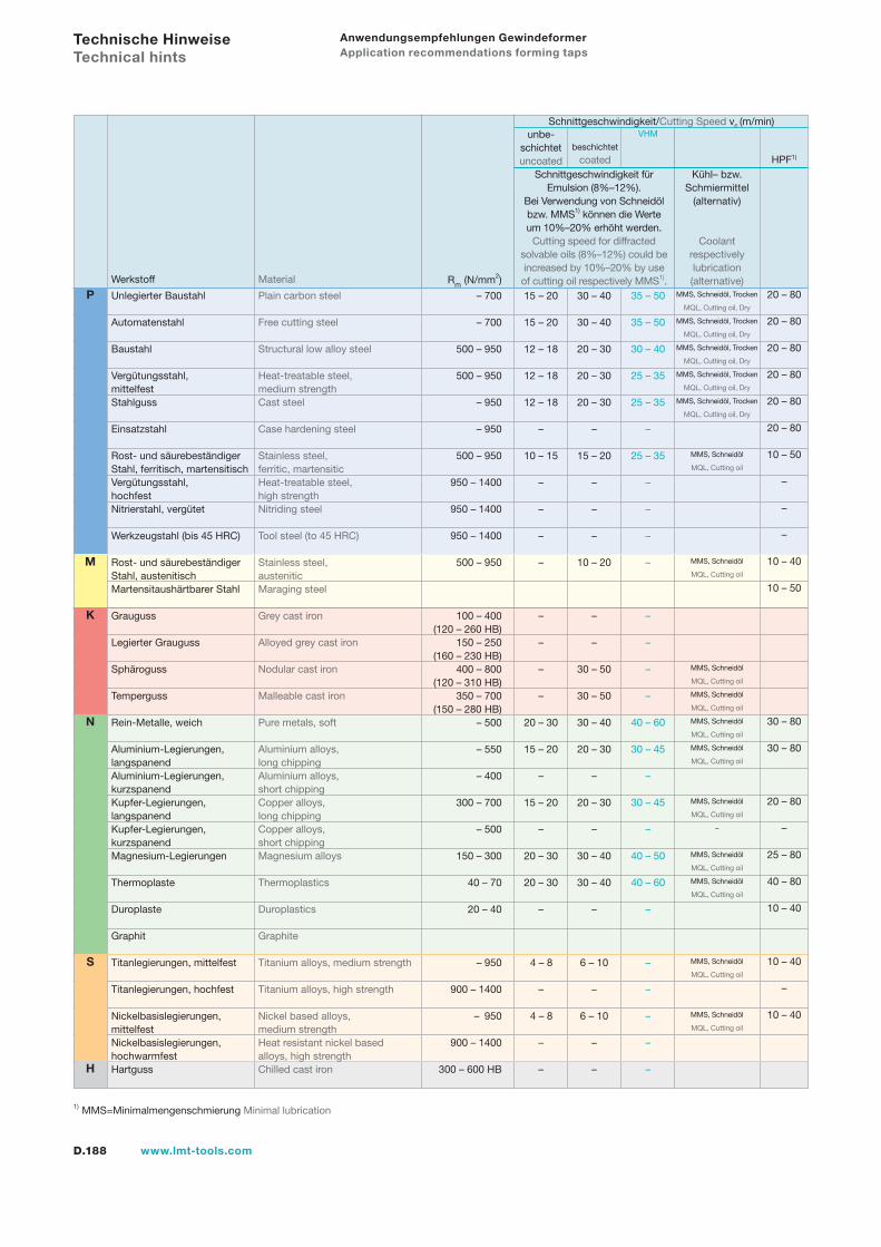
D.188 www.lmt-tools.com
Anwendungsempfehlungen Gewindeformer Application recommendations forming taps
Werkstoff Material
– 700
– 700
500 – 950
500 – 950
– 950
– 950
500 – 950
950 – 1400
950 – 1400
950 – 1400
500 – 950
100 – 400 (120 – 260 HB) 150 – 250 (160 – 230 HB) 400 – 800 (120 – 310 HB) 350 – 700 (150 – 280 HB) – 500
– 550
– 400
300 – 700
– 500
150 – 300
40 – 70
20 – 40
– 950
900 – 1400
– 950
900 – 1400
300 – 600 HB
Rm (N/mm2)
Schnittgeschwindigkeit/Cutting Speed vc (m/min)
15 – 20
15 – 20
12 – 18
12 – 18
12 – 18
–
10 – 15
–
–
–
–
–
–
–
–
20 – 30
15 – 20
–
15 – 20
–
20 – 30
20 – 30
–
4 – 8
–
4 – 8
–
–
35 – 50
35 – 50
30 – 40
25 – 35
25 – 35
–
25 – 35
–
–
–
–
–
–
–
–
40 – 60
30 – 45
–
30 – 45
–
40 – 50
40 – 60
–
–
–
–
–
–
MMS, Schneidöl, Trocken
MQL, Cutting oil, Dry
MMS, Schneidöl, Trocken
MQL, Cutting oil, Dry
MMS, Schneidöl, Trocken
MQL, Cutting oil, Dry
MMS, Schneidöl, Trocken
MQL, Cutting oil, Dry
MMS, Schneidöl, Trocken
MQL, Cutting oil, Dry
MMS, Schneidöl
MQL, Cutting oil
MMS, Schneidöl
MQL, Cutting oil
MMS, Schneidöl
MQL, Cutting oil
MMS, Schneidöl
MQL, Cutting oil
MMS, Schneidöl
MQL, Cutting oil
MMS, Schneidöl
MQL, Cutting oil
MMS, Schneidöl
MQL, Cutting oil
–
MMS, Schneidöl
MQL, Cutting oil
MMS, Schneidöl
MQL, Cutting oil
MMS, Schneidöl
MQL, Cutting oil
MMS, Schneidöl
MQL, Cutting oil
unbe-schichtetuncoated
Schnittgeschwindigkeit für Emulsion (8%–12%).
Bei Verwendung von Schneidöl bzw. MMS1) können die Werte um 10%–20% erhöht werden.
Cutting speed for diffracted solvable oils (8%–12%) could be increased by 10%–20% by use of cutting oil respectively MMS1).
Kühl– bzw. Schmiermittel
(alternativ)
Coolant respectively lubrication (alternative)
beschichtet
coated
VHM
Unlegierter Baustahl Plain carbon steel Automatenstahl Free cutting steel Baustahl Structural low alloy steel Vergütungsstahl, Heat-treatable steel, mittelfest medium strengthStahlguss Cast steel Einsatzstahl Case hardening steel Rost- und säurebeständiger Stainless steel, Stahl, ferritisch, martensitisch ferritic, martensiticVergütungsstahl, Heat-treatable steel, hochfest high strengthNitrierstahl, vergütet Nitriding steel Werkzeugstahl (bis 45 HRC) Tool steel (to 45 HRC) Rost- und säurebeständiger Stainless steel, Stahl, austenitisch austeniticMartensitaushärtbarer Stahl Maraging steel
Grauguss Grey cast iron
Legierter Grauguss Alloyed grey cast iron
Sphäroguss Nodular cast iron
Temperguss Malleable cast iron
Rein-Metalle, weich Pure metals, soft Aluminium-Legierungen, Aluminium alloys, langspanend long chippingAluminium-Legierungen, Aluminium alloys, kurzspanend short chippingKupfer-Legierungen, Copper alloys, langspanend long chippingKupfer-Legierungen, Copper alloys, kurzspanend short chippingMagnesium-Legierungen Magnesium alloys Thermoplaste Thermoplastics
Duroplaste Duroplastics Graphit Graphite
Titanlegierungen, mittelfest Titanium alloys, medium strength
Titanlegierungen, hochfest Titanium alloys, high strength Nickelbasislegierungen, Nickel based alloys, mittelfest medium strengthNickelbasislegierungen, Heat resistant nickel based hochwarmfest alloys, high strengthHartguss Chilled cast iron
30 – 40
30 – 40
20 – 30
20 – 30
20 – 30
–
15 – 20
–
–
–
10 – 20
–
–
30 – 50
30 – 50
30 – 40
20 – 30
–
20 – 30
–
30 – 40
30 – 40
–
6 – 10
–
6 – 10
–
–
Technische Hinweise Technical hints
1) MMS=Minimalmengenschmierung Minimal lubrication
N
S
H
P
K
M
20 – 80
20 – 80
20 – 80
20 – 80
20 – 80
20 – 80
10 – 50
–
–
–
10 – 40
10 – 50
30 – 80
30 – 80
20 – 80
–
25 – 80
40 – 80
10 – 40
10 – 40
–
10 – 40
HPF1)
D.189www.lmt-tools.com
NotizenNotes
Gew
inde
n Th
read
ing
D.190 www.lmt-tools.com
GewindefräserThread Milling Cutters

D.191www.lmt-tools.com
D.192 Auswahlübersicht Selection tableD.193 Typenbeschreibungen Descriptions of typesD.194 Vollhartmetall-Gewindefräser Solid carbide thread milling cuttersD.197 Gewindefräser mit Wendeplatten Thread milling cutters with indexable insertsD.199 Schnittwertempfehlungen Cutting data recommendations
GewindefräserThread milling cutters
Gew
inde
n Th
read
ing
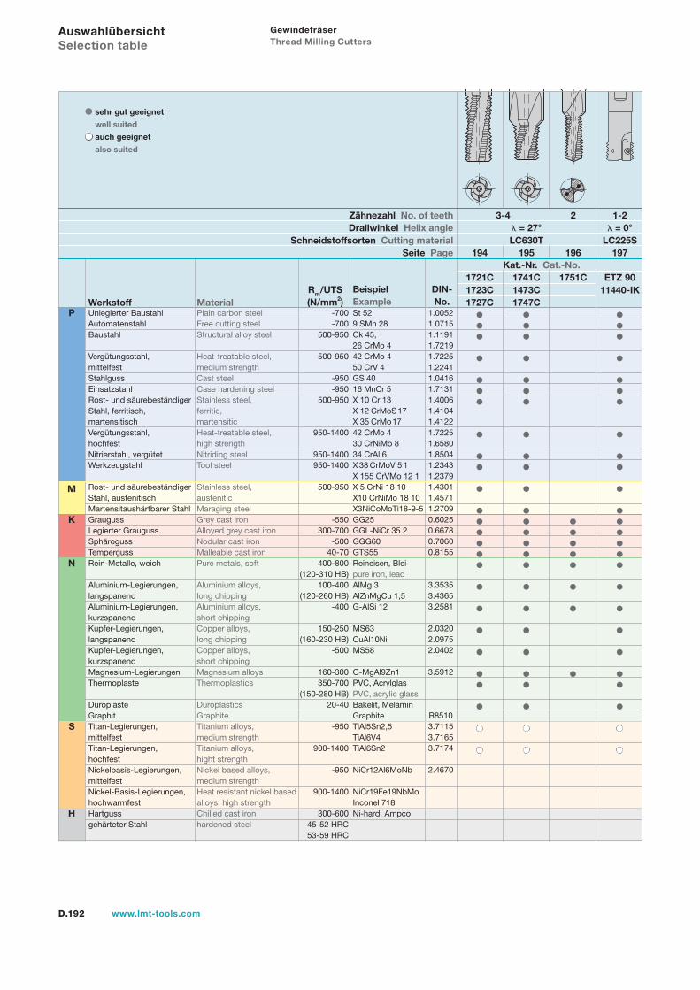
D.192 www.lmt-tools.com
Gewindefräser Thread Milling Cutters
Unlegierter Baustahl Plain carbon steelAutomatenstahl Free cutting steelBaustahl Structural alloy steel
Vergütungsstahl, Heat-treatable steel, mittelfest medium strengthStahlguss Cast steelEinsatzstahl Case hardening steel Rost- und säurebeständiger Stainless steel, Stahl, ferritisch, ferritic,martensitisch martensiticVergütungsstahl, Heat-treatable steel, hochfest high strengthNitrierstahl, vergütet Nitriding steelWerkzeugstahl Tool steel
Rost- und säurebeständiger Stainless steel,Stahl, austenitisch austeniticMartensitaushärtbarer Stahl Maraging steelGrauguss Grey cast ironLegierter Grauguss Alloyed grey cast ironSphäroguss Nodular cast ironTemperguss Malleable cast ironRein-Metalle, weich Pure metals, soft
Aluminium-Legierungen, Aluminium alloys, langspanend long chippingAluminium-Legierungen, Aluminium alloys,kurzspanend short chippingKupfer-Legierungen, Copper alloys,langspanend long chippingKupfer-Legierungen, Copper alloys,kurzspanend short chippingMagnesium-Legierungen Magnesium alloysThermoplaste Thermoplastics
Duroplaste DuroplasticsGraphit GraphiteTitan-Legierungen, Titanium alloys,mittelfest medium strengthTitan-Legierungen, Titanium alloys,hochfest hight strengthNickelbasis-Legierungen, Nickel based alloys,mittelfest medium strengthNickel-Basis-Legierungen, Heat resistant nickel basedhochwarmfest alloys, high strengthHartguss Chilled cast irongehärteter Stahl hardened steel
-700-700
500-950
500-950
-950-950
500-950
950-1400
950-1400950-1400
500-950
-550300-700
-50040-70
400-800 (120-310 HB)
100-400 (120-260 HB)
-400
150-250 (160-230 HB)
-500
160-300350-700
(150-280 HB)20-40
-950
900-1400
-950
900-1400
300-60045-52 HRC 53-59 HRC
St 529 SMn 28Ck 45, 26 CrMo 442 CrMo 4 50 CrV 4GS 4016 MnCr 5X 10 Cr 13 X 12 CrMoS 17 X 35 CrMo 1742 CrMo 4 30 CrNiMo 834 CrAl 6X 38 CrMoV 5 1 X 155 CrVMo 12 1X 5 CrNi 18 10 X10 CrNiMo 18 10X3NiCoMoTi18-9-5GG25GGL-NiCr 35 2GGG60GTS55Reineisen, Blei pure iron, leadAlMg 3 AlZnMgCu 1,5G-AlSi 12
MS63 CuAl10NiMS58
G-MgAl9Zn1PVC, Acrylglas PVC, acrylic glassBakelit, MelaminGraphiteTiAl5Sn2,5 TiAl6V4TiAl6Sn2
NiCr12Al6MoNb
NiCr19Fe19NbMo Inconel 718Ni-hard, Ampco
1.00521.07151.1191 1.72191.7225 1.22411.04161.71311.4006 1.41041.41221.7225 1.65801.85041.2343 1.23791.4301 1.45711.27090.60250.66780.70600.8155
3.3535 3.43653.2581
2.03202.09752.0402
3.5912
R85103.7115 3.71653.7174
2.4670
H
S
N
K
M
P
BeispielExample
DIN-No.Werkstoff Material
Rm/UTS(N/mm2)
Zähnezahl No. of teethDrallwinkel Helix angle
Schneidstoffsorten Cutting materialSeite Page
3-4 2 1-2 = 27° = 0° LC630T LC225S 194 195 196 197 Kat.-Nr. Cat.-No. 1721C 1741C 1751C ETZ 90 1723C 1473C 11440-IK 1727C 1747C
sehr gut geeignet
well suited
auch geeignet
also suited
Auswahlübersicht Selection table
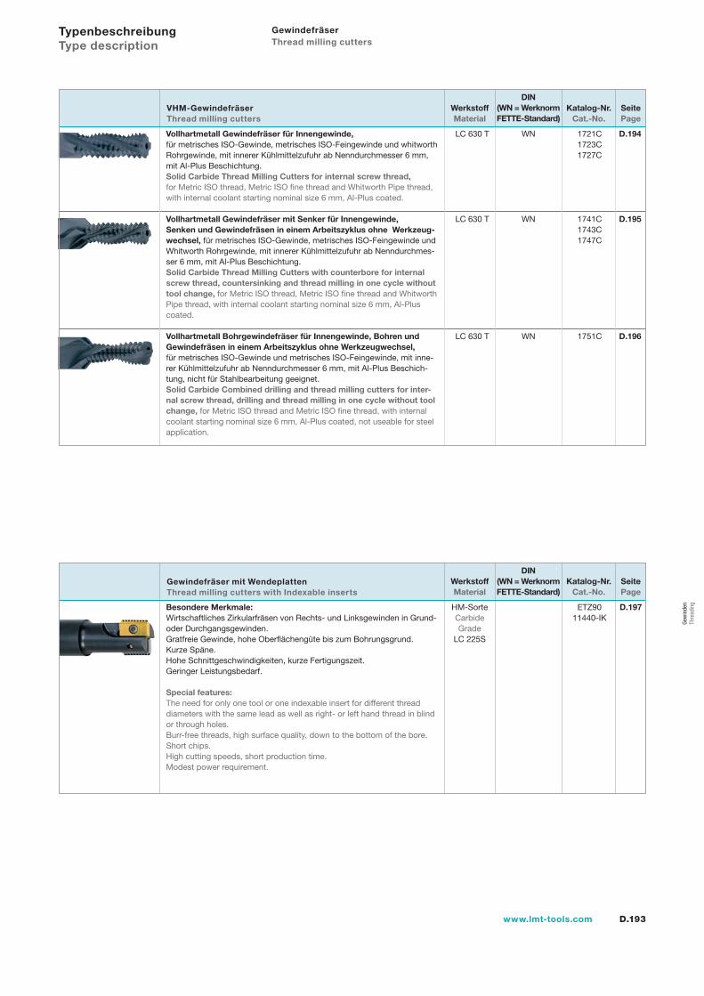
D.193www.lmt-tools.com
Gewindefräser Thread milling cutters
Vollhartmetall Gewindefräser für Innengewinde, für metrisches ISO-Gewinde, metrisches ISO-Feingewinde und whitworth Rohrgewinde, mit innerer Kühlmittelzufuhr ab Nenndurchmesser 6 mm, mit Al-Plus Beschichtung.Solid Carbide Thread Milling Cutters for internal screw thread, for Metric ISO thread, Metric ISO fine thread and Whitworth Pipe thread, with internal coolant starting nominal size 6 mm, Al-Plus coated.
Vollhartmetall Gewindefräser mit Senker für Innengewinde, Senken und Gewindefräsen in einem Arbeitszyklus ohne Werkzeug-wechsel, für metrisches ISO-Gewinde, metrisches ISO-Feingewinde und Whitworth Rohrgewinde, mit innerer Kühlmittelzufuhr ab Nenndurchmes-ser 6 mm, mit Al-Plus Beschichtung.Solid Carbide Thread Milling Cutters with counterbore for internal screw thread, countersinking and thread milling in one cycle without tool change, for Metric ISO thread, Metric ISO fine thread and Whitworth Pipe thread, with internal coolant starting nominal size 6 mm, Al-Plus coated.
Vollhartmetall Bohrgewindefräser für Innengewinde, Bohren und Gewindefräsen in einem Arbeitszyklus ohne Werkzeugwechsel, für metrisches ISO-Gewinde und metrisches ISO-Feingewinde, mit inne-rer Kühlmittelzufuhr ab Nenndurchmesser 6 mm, mit Al-Plus Beschich-tung, nicht für Stahlbearbeitung geeignet.Solid Carbide Combined drilling and thread milling cutters for inter-nal screw thread, drilling and thread milling in one cycle without tool change, for Metric ISO thread and Metric ISO fine thread, with internal coolant starting nominal size 6 mm, Al-Plus coated, not useable for steel application.
LC 630 T WN 1721C D.194 1723C 1727C
LC 630 T WN 1741C D.195 1743C 1747C
LC 630 T WN 1751C D.196
SeitePage
Katalog-Nr.Cat.-No.
DIN(WN = Werknorm FETTE-Standard)
WerkstoffMaterial
Typenbeschreibung Type description
Besondere Merkmale:Wirtschaftliches Zirkularfräsen von Rechts- und Linksgewinden in Grund- oder Durchgangsgewinden. Gratfreie Gewinde, hohe Oberflächengüte bis zum Bohrungsgrund.Kurze Späne.Hohe Schnittgeschwindigkeiten, kurze Fertigungszeit.Geringer Leistungsbedarf. Special features:The need for only one tool or one indexable insert for different thread diameters with the same lead as well as right- or left hand thread in blind or through holes.Burr-free threads, high surface quality, down to the bottom of the bore.Short chips.High cutting speeds, short production time.Modest power requirement.
HM-SorteCarbide Grade
LC 225S
ETZ9011440-IK
D.197
SeitePage
Katalog-Nr.Cat.-No.
DIN(WN = Werknorm FETTE-Standard)
WerkstoffMaterial
VHM-Gewindefräser Thread milling cutters
Gewindefräser mit Wendeplatten Thread milling cutters with Indexable inserts
Gew
inde
n Th
read
ing
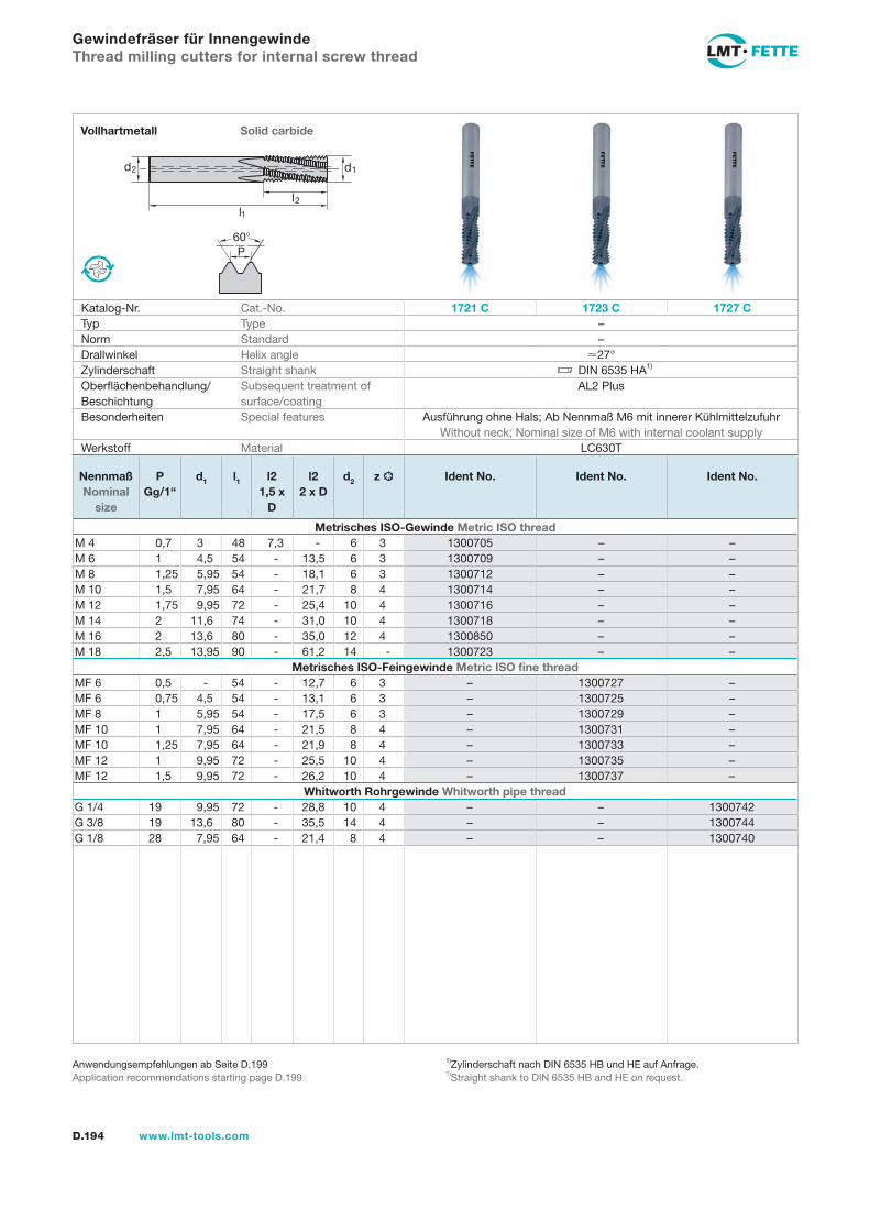
l1
d2 d1
l2
60P
D.194 www.lmt-tools.com
Solid carbideVollhartmetall
1)Zylinderschaft nach DIN 6535 HB und HE auf Anfrage.1)Straight shank to DIN 6535 HB and HE on request.
Anwendungsempfehlungen ab Seite D.199Application recommendations starting page D.199
Gewindefräser für InnengewindeThread milling cutters for internal screw thread
Katalog-Nr. Cat.-No. 1721 C 1723 C 1727 CTyp Type –Norm Standard –Drallwinkel Helix angle 27°Zylinderschaft Straight shank DIN 6535 HA1)
Oberflächenbehandlung/Beschichtung
Subsequent treatment of surface/coating
AL2 Plus
Besonderheiten Special features Ausführung ohne Hals; Ab Nennmaß M6 mit innerer Kühlmittelzufuhr Without neck; Nominal size of M6 with internal coolant supply
Werkstoff Material LC630T
Nennmaß Nominal
size
PGg/1“
d1 l1 l21,5 x
D
l22 x D
d2 z Ident No. Ident No. Ident No.
Metrisches ISO-Gewinde Metric ISO threadM 4 0,7 3 48 7,3 - 6 3 1300705 – –M 6 1 4,5 54 - 13,5 6 3 1300709 – –M 8 1,25 5,95 54 - 18,1 6 3 1300712 – –M 10 1,5 7,95 64 - 21,7 8 4 1300714 – –M 12 1,75 9,95 72 - 25,4 10 4 1300716 – –M 14 2 11,6 74 - 31,0 10 4 1300718 – –M 16 2 13,6 80 - 35,0 12 4 1300850 – –M 18 2,5 13,95 90 - 61,2 14 - 1300723 – –
Metrisches ISO-Feingewinde Metric ISO fine threadMF 6 0,5 - 54 - 12,7 6 3 – 1300727 –MF 6 0,75 4,5 54 - 13,1 6 3 – 1300725 –MF 8 1 5,95 54 - 17,5 6 3 – 1300729 –MF 10 1 7,95 64 - 21,5 8 4 – 1300731 –MF 10 1,25 7,95 64 - 21,9 8 4 – 1300733 –MF 12 1 9,95 72 - 25,5 10 4 – 1300735 –MF 12 1,5 9,95 72 - 26,2 10 4 – 1300737 –
Whitworth Rohrgewinde Whitworth pipe threadG 1/4 19 9,95 72 - 28,8 10 4 – – 1300742G 3/8 19 13,6 80 - 35,5 14 4 – – 1300744G 1/8 28 7,95 64 - 21,4 8 4 – – 1300740
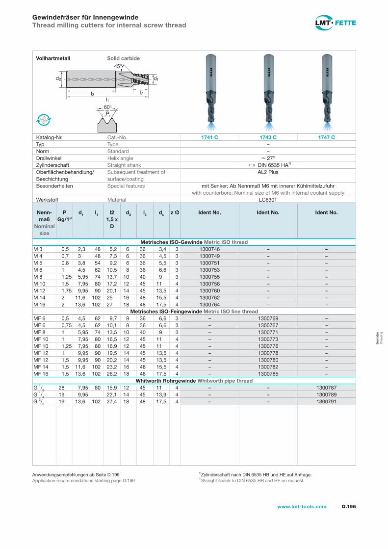
l1l3
d2 d1
l2
45°
60P
D.195www.lmt-tools.com
Solid carbideVollhartmetall
1)Zylinderschaft nach DIN 6535 HB und HE auf Anfrage.1)Straight shank to DIN 6535 HB and HE on request.
Anwendungsempfehlungen ab Seite D.199Application recommendations starting page D.199
Gewindefräser für InnengewindeThread milling cutters for internal screw thread
Katalog-Nr. Cat.-No. 1741 C 1743 C 1747 CTyp Type –Norm Standard –Drallwinkel Helix angle 27°Zylinderschaft Straight shank DIN 6535 HA1)
Oberflächenbehandlung/Beschichtung
Subsequent treatment of surface/coating
AL2 Plus
Besonderheiten Special features mit Senker; Ab Nennmaß M6 mit innerer Kühlmittelzufuhr with counterbore; Nominal size of M6 with internal coolant supply
Werkstoff Material LC630T
Nenn-maß
Nominal size
PGg/1“
d1 l1 l21,5 x
D
d2 l3 ds z Ident No. Ident No. Ident No.
Metrisches ISO-Gewinde Metric ISO threadM 3 0,5 2,3 48 5,2 6 36 3,4 3 1300746 – –M 4 0,7 3 48 7,3 6 36 4,5 3 1300749 – –M 5 0,8 3,8 54 9,2 6 36 5,5 3 1300751 – –M 6 1 4,5 62 10,5 8 36 6,6 3 1300753 – –M 8 1,25 5,95 74 13,7 10 40 9 3 1300755 – –M 10 1,5 7,95 80 17,2 12 45 11 4 1300758 – –M 12 1,75 9,95 90 20,1 14 45 13,5 4 1300760 – –M 14 2 11,6 102 25 16 48 15,5 4 1300762 – –M 16 2 13,6 102 27 18 48 17,5 4 1300764 – –
Metrisches ISO-Feingewinde Metric ISO fine threadMF 6 0,5 4,5 62 9,7 8 36 6,6 3 – 1300769 –MF 6 0,75 4,5 62 10,1 8 36 6,6 3 – 1300767 –MF 8 1 5,95 74 13,5 10 40 9 3 – 1300771 –MF 10 1 7,95 80 16,5 12 45 11 4 – 1300773 –MF 10 1,25 7,95 80 16,9 12 45 11 4 – 1300776 –MF 12 1 9,95 90 19,5 14 45 13,5 4 – 1300778 –MF 12 1,5 9,95 90 20,2 14 45 13,5 4 – 1300780 –MF 14 1,5 11,6 102 23,2 16 48 15,5 4 – 1300782 –MF 16 1,5 13,6 102 26,2 18 48 17,5 4 – 1300785 –
Whitworth Rohrgewinde Whitworth pipe threadG 1/8 28 7,95 80 15,9 12 45 11 4 – – 1300787G 1/4 19 9,95 22,1 14 45 13,9 4 – – 1300789G 3/8 19 13,6 102 27,4 18 48 17,5 4 – – 1300791
Gew
inde
n Th
read
ing
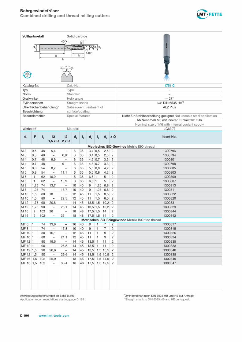
60P
l1l3
d2 dk
l2
45° l6dsd1
140°
D.196 www.lmt-tools.com
Solid carbideVollhartmetall
1)Zylinderschaft nach DIN 6535 HB und HE auf Anfrage.1)Straight shank to DIN 6535 HB and HE on request.
Anwendungsempfehlungen ab Seite D.199Application recommendations starting page D.199
BohrgewindefräserCombined drilling and thread milling cutters
Katalog-Nr. Cat.-No. 1751 CTyp Type –Norm Standard –Drallwinkel Helix angle 27°Zylinderschaft Straight shank DIN 6535 HA1)
Oberflächenbehandlung/Beschichtung
Subsequent treatment of surface/coating
AL2 Plus
Besonderheiten Special features Nicht für Stahlbearbeitung geeignet Not useable steel applicationAb Nennmaß M6 mit innerer Kühlmittelzufuhr
Nominal size of M6 with internal coolant supplyWerkstoff Material LC630T
d1 P l1 l21,5 x D
l22 x D
d2 l3 ds l6 dk z Ident No.
Metrisches ISO-Gewinde Metric ISO threadM 3 0,5 48 5,4 – 6 36 3,4 0,5 2,5 2 1300796M 3 0,5 48 – 6,9 6 36 3,4 0,5 2,5 2 1300794M 4 0,7 48 6,9 – 6 36 4,5 0,7 3,3 2 1300801M 4 0,7 48 – 9 6 36 4,5 0,7 3,3 2 1300798M 5 0,8 54 8,7 – 6 36 5,5 0,8 4,2 2 1300805M 5 0,8 54 – 11,1 6 36 5,5 0,8 4,2 2 1300803M 6 1 62 10,9 – 8 36 6,6 1 5 2 1300809M 6 1 62 – 13,9 8 36 6,6 1 5 2 1300807M 8 1,25 74 13,7 – 10 40 9 1,25 6,8 2 1300813M 8 1,25 74 – 18,7 10 40 9 1,25 6,8 2 1300811M 10 1,5 80 18 – 12 45 11 1,5 8,5 2 1300822M 10 1,5 80 – 22,5 12 45 11 1,5 8,5 2 1300820M 12 1,75 90 20,8 – 14 45 13,5 1,5 10,2 2 1300831M 12 1,75 90 – 26,1 14 45 13,5 1,5 10,2 2 1300829M 16 2 102 26 – 18 48 17,5 1,5 14 2 1300844M 16 2 102 – 36 18 48 17,5 1,5 14 2 1300842
Metrisches ISO-Feingewinde Metric ISO fine threadMF 8 1 74 13,8 – 10 40 9 1 7 2 1300817MF 8 1 74 – 17,8 10 40 9 1 7 2 1300815MF 10 1 80 16,1 – 12 45 11 1 9 2 1300826MF 10 1 80 – 21,1 12 45 11 1 9 2 1300824MF 12 1 90 19,5 – 14 45 13,5 1 11 2 1300835MF 12 1 90 – 25,5 14 45 13,5 1 11 2 1300833MF 12 1,5 90 20,6 – 14 45 13,5 1,5 10,5 2 1300840MF 12 1,5 90 – 26,6 14 45 13,5 1,5 10,5 2 1300838MF 16 1,5 102 25,9 – 18 45 17,5 1,5 14,5 2 1300849MF 16 1,5 102 – 33,4 18 48 17,5 1,5 12,5 2 1300847
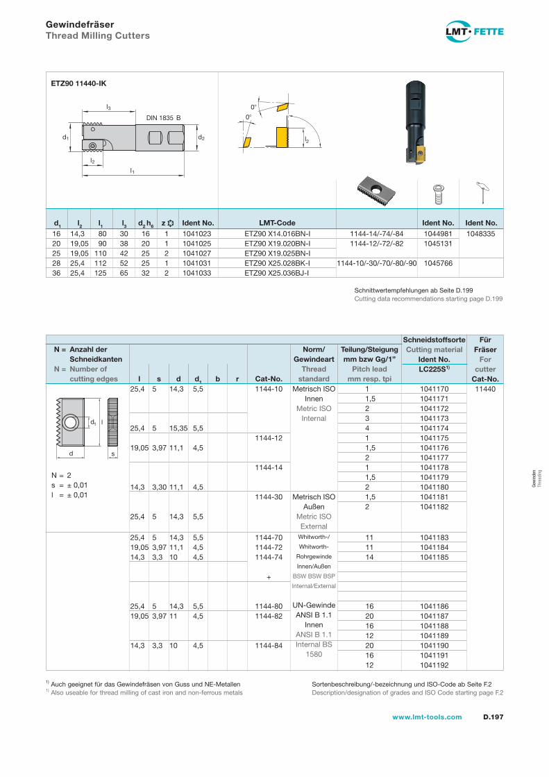
D.197www.lmt-tools.com
16 14,3 80 30 16 1 1041023 20 19,05 90 38 20 1 1041025 25 19,05 110 42 25 2 1041027 28 25,4 112 52 25 1 1041031 36 25,4 125 65 32 2 1041033
10449811045131
1045766
ETZ90 X14.016BN-I ETZ90 X19.020BN-I ETZ90 X19.025BN-I ETZ90 X25.028BK-I ETZ90 X25.036BJ-I
1144-14/-74/-841144-12/-72/-82
1144-10/-30/-70/-80/-90
Gewindefräser Thread Milling Cutters
d2d1
l1
l3
DIN 1835 B
l2
1048335
Ident No.Ident No.LMT-Code
l2
0
0
ETZ90 11440-IK
Schnittwertempfehlungen ab Seite D.199Cutting data recommendations starting page D.199
d1 l2 l1 l3 d2 h6 z Ident No.
Metrisch ISO Innen
Metric ISO Internal
Metrisch ISO Außen
Metric ISO External
1 1,5 2 3 4 1 1,5 2 1 1,5 2 1,5 2
1144-10
1144-12
1144-14
1144-30
25,4 5 14,3 5,5 25,4 5 15,35 5,5 19,05 3,97 11,1 4,5 14,3 3,30 11,1 4,5 25,4 5 14,3 5,5
1041170 1041171 1041172 1041173 1041174 1041175 1041176 1041177 1041178 1041179 1041180 1041181 1041182
11440
l
sd
d1
N = 2 s = ± 0,01 l = ± 0,01
N = Anzahl der Schneidkanten N = Number of cutting edges l s d d1 b r Cat-No.
Schneidstoffsorte Cutting material
Ident No. LC225S1)
Für Fräser
For cutter
Cat-No.
Norm/Gewindeart
Thread standard
Teilung/Steigungmm bzw Gg/1”
Pitch lead mm resp. tpi
Whitworth-/
Whitworth-
Rohrgewinde
Innen/Außen
BSW BSW BSP
Internal/External
UN-Gewinde ANSI B 1.1
Innen ANSI B 1.1 Internal BS
1580
11 11 14
16 20 16 12 20 16 12
1144-70 1144-72 1144-74
+
1144-80 1144-82
1144-84
25,4 5 14,3 5,5 19,05 3,97 11,1 4,5 14,3 3,3 10 4,5
25,4 5 14,3 5,5 19,05 3,97 11 4,5 14,3 3,3 10 4,5
1041183 1041184 1041185
1041186 1041187 1041188 1041189 1041190 1041191 1041192
1) Auch geeignet für das Gewindefräsen von Guss und NE-Metallen 1) Also useable for thread milling of cast iron and non-ferrous metals
Sortenbeschreibung/-bezeichnung und ISO-Code ab Seite F.2Description/designation of grades and ISO Code starting page F.2
Gew
inde
n Th
read
ing
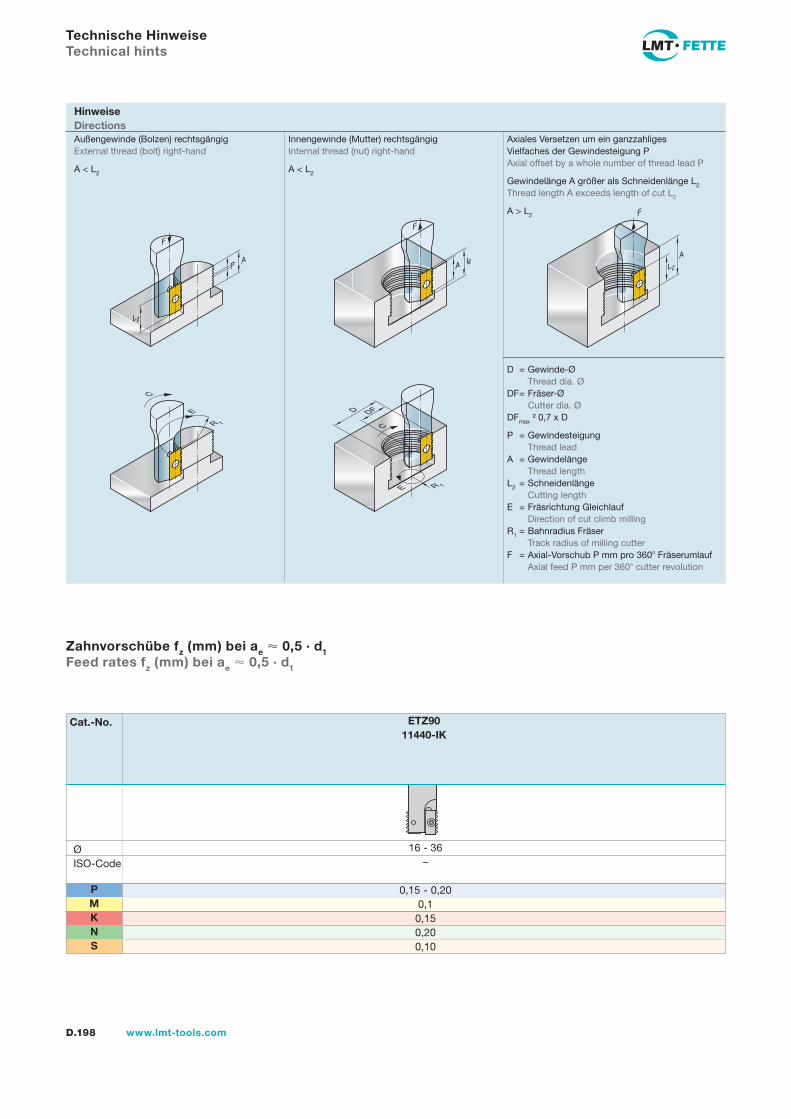
D.198 www.lmt-tools.com
Technische Hinweise Technical hints
Hinweise Directions
A
F
L2
F
L2A
R 1
D DF
E
C
AP
F
L2
C
R 1
E
Innengewinde (Mutter) rechtsgängigInternal thread (nut) right-hand
A < L2
Außengewinde (Bolzen) rechtsgängigExternal thread (bolt) right-hand
A < L2
Axiales Versetzen um ein ganzzahliges Vielfaches der Gewindesteigung PAxial offset by a whole number of thread lead P
Gewindelänge A größer als Schneidenlänge L2
Thread length A exceeds length of cut L2
A > L2
D = Gewinde-Ø Thread dia. Ø
DF = Fräser-Ø Cutter dia. Ø
DFmax ² 0,7 x D
P = Gewindesteigung Thread leadA = Gewindelänge Thread lengthL2 = Schneidenlänge Cutting lengthE = Fräsrichtung Gleichlauf Direction of cut climb millingR1 = Bahnradius Fräser Track radius of milling cutterF = Axial-Vorschub P mm pro 360 Fräserumlauf Axial feed P mm per 360 cutter revolution
PMKNS
Zahnvorschübe fz (mm) bei ae 0,5 · d1 Feed rates fz (mm) bei ae 0,5 · d1
Cat.-No.
Ø ISO-Code
16 - 36–
0,15 - 0,200,10,150,200,10
ETZ9011440-IK
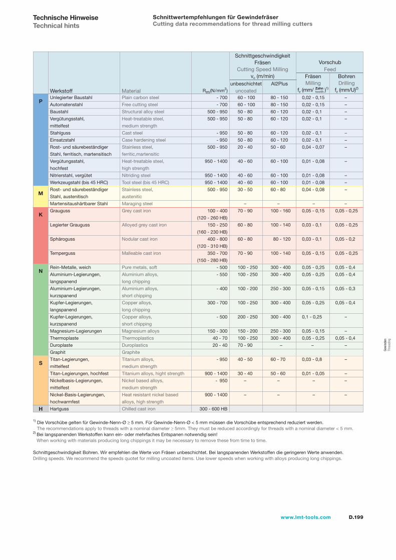
D.199www.lmt-tools.com
Gew
inde
n Th
read
ing
Schnittwertempfehlungen für GewindefräserCutting data recommendations for thread milling cutters
1) Die Vorschübe gelten für Gewinde-Nenn-Ø ≥ 5 mm. Für Gewinde-Nenn-Ø < 5 mm müssen die Vorschübe entsprechend reduziert werden. The recommendations apply to threads with a nominal diameter ≥ 5mm. They must be reduced accordingly for threads with a nominal diameter < 5 mm.
2) Bei langspanenden Werkstoffen kann ein- oder mehrfaches Entspanen notwendig sein! When working with materials producing long chippings it may be necessary to remove these from time to time.
Schnittgeschwindigkeit Bohren. Wir empfehlen die Werte von Fräsen unbeschichtet. Bei langspanenden Werkstoffen die geringeren Werte anwenden.Drilling speeds. We recommend the speeds quotet for milling uncoated items. Use lower speeds when working with alloys producing long chippings.
Fräsen Milling
fz (mm/ )1)
Bohren Drilling
fz (mm/U)2)Werkstoff Material
- 700
- 700
500 - 950
500 - 950
- 950
- 950
500 - 950
950 - 1400
950 - 1400
950 - 1400
500 - 950
100 - 400
(120 - 260 HB)
150 - 250
(160 - 230 HB)
400 - 800
(120 - 310 HB)
350 - 700
(150 - 280 HB)
- 500
- 550
- 400
300 - 700
- 500
150 - 300
40 - 70
20 - 40
- 950
900 - 1400
- 950
900 - 1400
300 - 600 HB
Rm(N/mm2)
60 - 100 80 - 150 0,02 - 0,15 –
60 - 100 80 - 150 0,02 - 0,15 –
50 - 80 60 - 120 0,02 - 0,1 –
50 - 80 60 - 120 0,02 - 0,1 –
50 - 80 60 - 120 0,02 - 0,1 –
50 - 80 60 - 120 0,02 - 0,1 –
20 - 40 50 - 60 0,04 - 0,07 –
40 - 60 60 - 100 0,01 - 0,08 –
40 - 60 60 - 100 0,01 - 0,08 –
40 - 60 60 - 100 0,01 - 0,08 –
30 - 50 60 - 80 0,04 - 0,08 –
– – – –
70 - 90 100 - 160 0,05 - 0,15 0,05 - 0,25
60 - 80 100 - 140 0,03 - 0,1 0,05 - 0,25
60 - 80 80 - 120 0,03 - 0,1 0,05 - 0,2
70 - 90 100 - 140 0,05 - 0,15 0,05 - 0,25
100 - 250 300 - 400 0,05 - 0,25 0,05 - 0,4
100 - 250 300 - 400 0,05 - 0,25 0,05 - 0,4
100 - 200 250 - 300 0,05 - 0,15 0,05 - 0,3
100 - 250 300 - 400 0,05 - 0,25 0,05 - 0,4
200 - 250 300 - 400 0,1 - 0,25 –
150 - 200 250 - 300 0,05 - 0,15 –
100 - 250 300 - 400 0,05 - 0,25 0,05 - 0,4
70 - 90 – – –
40 - 50 60 - 70 0,03 - 0,8 –
30 - 40 50 - 60 0,01 - 0,05 –
– – – –
– – – –
Vorschub Feed
Schnittgeschwindigkeit Fräsen
Cutting Speed Millingvc (m/min)
unbeschichtetuncoated
Al2PlusZahntooth
Technische HinweiseTechnical hints
P
M
K
N
S
H
Unlegierter Baustahl Plain carbon steel
Automatenstahl Free cutting steel
Baustahl Structural alloy steel
Vergütungsstahl, Heat-treatable steel,
mittelfest medium strength
Stahlguss Cast steel
Einsatzstahl Case hardening steel
Rost- und säurebeständiger Stainless steel,
Stahl, ferritisch, martensitisch ferritic,martensitic
Vergütungsstahl, Heat-treatable steel,
hochfest high strength
Nitrierstahl, vergütet Nitriding steel
Werkzeugstahl (bis 45 HRC) Tool steel (bis 45 HRC)
Rost- und säurebeständiger Stainless steel,
Stahl, austenitisch austenitic
Martensitaushärtbarer Stahl Maraging steel
Grauguss Grey cast iron
Legierter Grauguss Alloyed grey cast iron
Sphäroguss Nodular cast iron
Temperguss Malleable cast iron
Rein-Metalle, weich Pure metals, soft
Aluminium-Legierungen, Aluminium alloys,
langspanend long chipping
Aluminium-Legierungen, Aluminium alloys,
kurzspanend short chipping
Kupfer-Legierungen, Copper alloys,
langspanend long chipping
Kupfer-Legierungen, Copper alloys,
kurzspanend short chipping
Magnesium-Legierungen Magnesium alloys
Thermoplaste Thermoplastics
Duroplaste Duroplastics
Graphit Graphite
Titan-Legierungen, Titanium alloys,
mittelfest medium strength
Titan-Legierungen, hochfest Titanium alloys, hight strength
Nickelbasis-Legierungen, Nickel based alloys,
mittelfest medium strength
Nickel-Basis-Legierungen, Heat resistant nickel based
hochwarmfest alloys, high strength
Hartguss Chilled cast iron
D.200 www.lmt-tools.com
SchneideisenDies

D.201www.lmt-tools.com
Gew
inde
n Th
read
ing
SchneideisenDies
D.202 Auswahlübersicht Selection tableD.203 Typenbeschreibungen Descriptions of typesD.205 M – Metrisches ISO-Gewinde DIN 13 M – Metric ISO threadD.207 MF – Metrisches ISO-Feingewinde DIN 13 MF – Metric ISO fine threadD.209 UNC – Grobgewinde UNC – Coarse threadD.210 UNF – Feingewinde UNF – Fine threadD.211 G – Whitworth Rohrgewinde (BSP) G – Whitworth pipe thread (BSP)D.212 BSW – Whitworth Gewinde BSW – Whitworth threadD.213 PG – Stahlpanzerrohr-Gewinde DIN 40-430 PG – Steel conduit threadD.214 NPT – Amerikanisches kegeliges Rohrgewinde NPT – American taper pipe threadD.215 Anwendungsempfehlungen Application recommendations
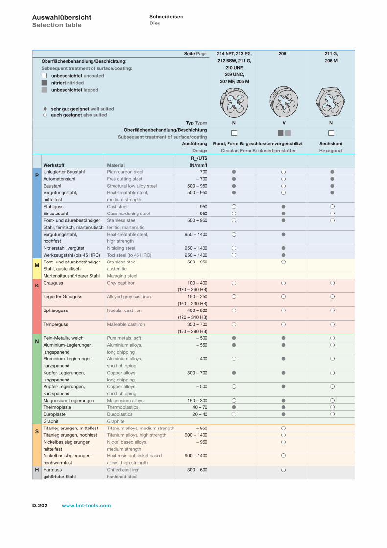
D.202 www.lmt-tools.com
sehr gut geeignet well suited auch geeignet also suited
Rm/UTS
Werkstoff Material (N/mm2)Unlegierter Baustahl Plain carbon steel – 700
Automatenstahl Free cutting steel – 700
Baustahl Structural low alloy steel 500 – 950
Vergütungsstahl, Heat-treatable steel, 500 – 950
mittelfest medium strength
Stahlguss Cast steel – 950
Einsatzstahl Case hardening steel – 950
Rost- und säurebeständiger Stainless steel, 500 – 950
Stahl, ferritisch, martensitisch ferritic, martensitic
Vergütungsstahl, Heat-treatable steel, 950 – 1400
hochfest high strength
Nitrierstahl, vergütet Nitriding steel 950 – 1400
Werkzeugstahl (bis 45 HRC) Tool steel (to 45 HRC) 950 – 1400
Rost- und säurebeständiger Stainless steel, 500 – 950
Stahl, austenitisch austenitic
Martensitaushärtbarer Stahl Maraging steel
Grauguss Grey cast iron 100 – 400
(120 – 260 HB)
Legierter Grauguss Alloyed grey cast iron 150 – 250
(160 – 230 HB)
Sphäroguss Nodular cast iron 400 – 800
(120 – 310 HB)
Temperguss Malleable cast iron 350 – 700
(150 – 280 HB)
Rein-Metalle, weich Pure metals, soft – 500
Aluminium-Legierungen, Aluminium alloys, – 550
langspanend long chipping
Aluminium-Legierungen, Aluminium alloys, – 400
kurzspanend short chipping
Kupfer-Legierungen, Copper alloys, 300 – 700
langspanend long chipping
Kupfer-Legierungen, Copper alloys, – 500
kurzspanend short chipping
Magnesium-Legierungen Magnesium alloys 150 – 300
Thermoplaste Thermoplastics 40 – 70
Duroplaste Duroplastics 20 – 40
Graphit Graphite
Titanlegierungen, mittelfest Titanium alloys, medium strength – 950
Titanlegierungen, hochfest Titanium alloys, high strength 900 – 1400
Nickelbasislegierungen, Nickel based alloys, – 950
mittelfest medium strength
Nickelbasislegierungen, Heat resistant nickel based 900 – 1400
hochwarmfest alloys, high strength
Hartguss Chilled cast iron 300 – 600
gehärteter Stahl hardened steel
N V N
Rund, Form B: geschlossen-vorgeschlitzt Sechskant
Circular, Form B: closed-preslotted Hexagonal
Seite Page 214 NPT, 213 PG, 206 211 G,
212 BSW, 211 G, 206 M
210 UNF,
209 UNC,
207 MF, 205 M
Schneideisen Dies
Typ Types
Oberflächenbehandlung/Beschichtung
Subsequent treatment of surface/coating
Ausführung
Design
Oberflächenbehandlung/Beschichtung:
Subsequent treatment of surface/coating:
unbeschichtet uncoated
nitriert nitrided
unbeschichtet lapped
Auswahlübersicht Selection table
P
M
K
N
S
H
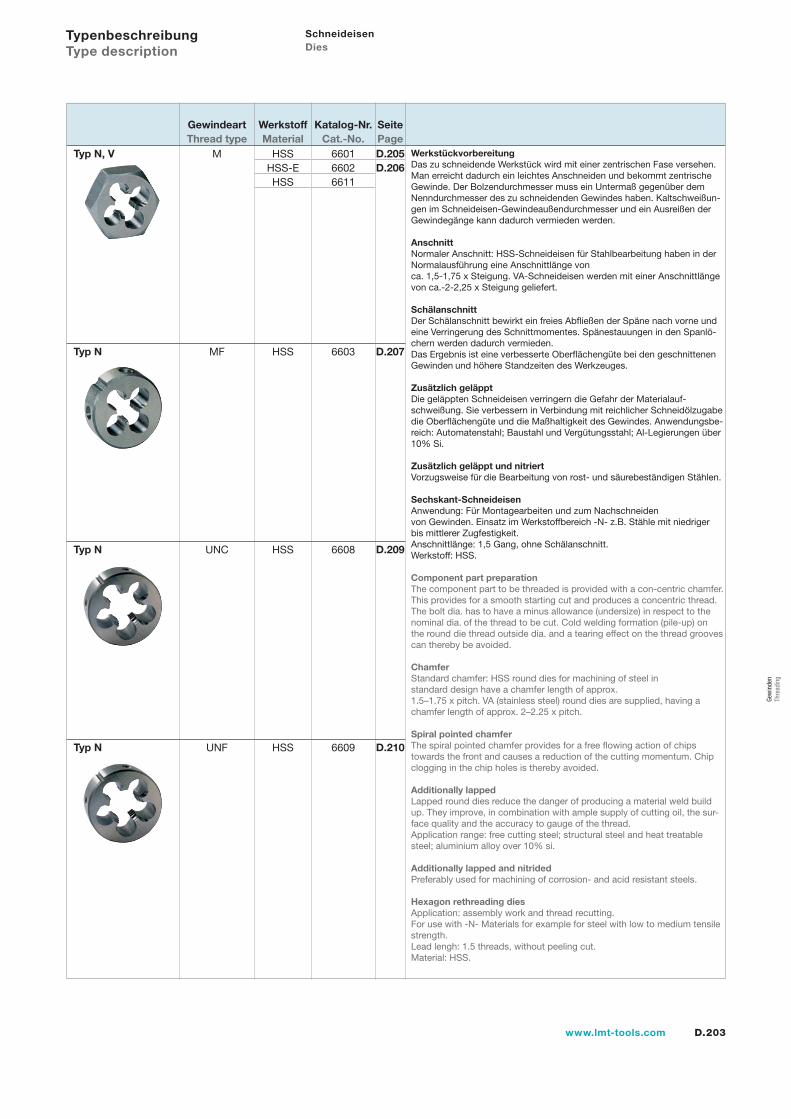
D.203www.lmt-tools.com
660166026611
6603
6608
6609
Schneideisen Dies
Werkstückvorbereitung Das zu schneidende Werkstück wird mit einer zentrischen Fase versehen. Man erreicht dadurch ein leichtes Anschneiden und bekommt zentrische Gewinde. Der Bolzendurchmesser muss ein Untermaß gegenüber dem Nenndurchmesser des zu schneidenden Gewindes haben. Kaltschweißun-gen im Schneideisen-Gewindeaußendurchmesser und ein Ausreißen der Gewindegänge kann dadurch vermieden werden.
Anschnitt Normaler Anschnitt: HSS-Schneideisen für Stahlbearbeitung haben in der Normalausführung eine Anschnittlänge von ca. 1,5-1,75 x Steigung. VA-Schneideisen werden mit einer Anschnittlänge von ca.-2-2,25 x Steigung geliefert.
Schälanschnitt Der Schälanschnitt bewirkt ein freies Abfließen der Späne nach vorne und eine Verringerung des Schnittmomentes. Spänestauungen in den Spanlö-chern werden dadurch vermieden. Das Ergebnis ist eine verbesserte Oberflächengüte bei den geschnittenen Gewinden und höhere Standzeiten des Werkzeuges.
Zusätzlich geläppt Die geläppten Schneideisen verringern die Gefahr der Materialauf-schweißung. Sie verbessern in Verbindung mit reichlicher Schneidölzugabe die Oberflächengüte und die Maßhaltigkeit des Gewindes. Anwendungsbe-reich: Automatenstahl; Baustahl und Vergütungsstahl; Al-Legierungen über 10% Si.
Zusätzlich geläppt und nitriert Vorzugsweise für die Bearbeitung von rost- und säurebeständigen Stählen.
Sechskant-Schneideisen Anwendung: Für Montagearbeiten und zum Nachschneiden von Gewinden. Einsatz im Werkstoffbereich -N- z.B. Stähle mit niedriger bis mittlerer Zugfestigkeit. Anschnittlänge: 1,5 Gang, ohne Schälanschnitt. Werkstoff: HSS.
Component part preparation The component part to be threaded is provided with a con-centric chamfer. This provides for a smooth starting cut and produces a concentric thread. The bolt dia. has to have a minus allowance (undersize) in respect to the nominal dia. of the thread to be cut. Cold welding formation (pile-up) on the round die thread outside dia. and a tearing effect on the thread grooves can thereby be avoided.
Chamfer Standard chamfer: HSS round dies for machining of steel in standard design have a chamfer length of approx. 1.5–1.75 x pitch. VA (stainless steel) round dies are supplied, having a chamfer length of approx. 2–2.25 x pitch.
Spiral pointed chamfer The spiral pointed chamfer provides for a free flowing action of chips towards the front and causes a reduction of the cutting momentum. Chip clogging in the chip holes is thereby avoided.
Additionally lapped Lapped round dies reduce the danger of producing a material weld build up. They improve, in combination with ample supply of cutting oil, the sur-face quality and the accuracy to gauge of the thread. Application range: free cutting steel; structural steel and heat treatable steel; aluminium alloy over 10% si.
Additionally lapped and nitrided Preferably used for machining of corrosion- and acid resistant steels.
Hexagon rethreading dies Application: assembly work and thread recutting. For use with -N- Materials for example for steel with low to medium tensile strength. Lead lengh: 1.5 threads, without peeling cut. Material: HSS.
M
MF
UNC
UNF
Typ N, V
Typ N
Typ N
Typ N
HSSHSS-EHSS
HSS
HSS
HSS
D.205D.206
D.207
D.209
D.210
SeitePage
GewindeartThread type
WerkstoffMaterial
Katalog-Nr.Cat.-No.
Typenbeschreibung Type description
Gew
inde
n Th
read
ing
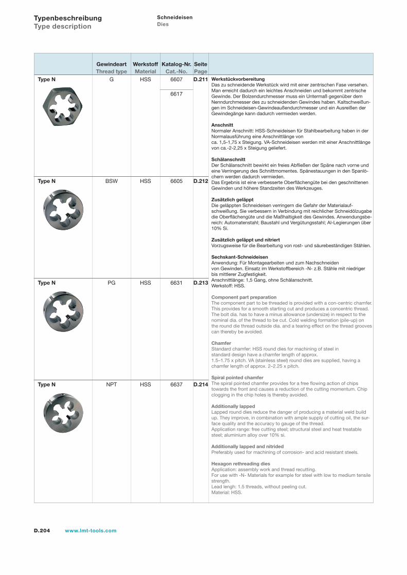
D.204 www.lmt-tools.com
Schneideisen Dies
Typenbeschreibung Type description
6607
6617
6605
6631
6637
HSS
HSS
HSS
HSS
Werkstückvorbereitung Das zu schneidende Werkstück wird mit einer zentrischen Fase versehen. Man erreicht dadurch ein leichtes Anschneiden und bekommt zentrische Gewinde. Der Bolzendurchmesser muss ein Untermaß gegenüber dem Nenndurchmesser des zu schneidenden Gewindes haben. Kaltschweißun-gen im Schneideisen-Gewindeaußendurchmesser und ein Ausreißen der Gewindegänge kann dadurch vermieden werden.
Anschnitt Normaler Anschnitt: HSS-Schneideisen für Stahlbearbeitung haben in der Normalausführung eine Anschnittlänge von ca. 1,5-1,75 x Steigung. VA-Schneideisen werden mit einer Anschnittlänge von ca.-2-2,25 x Steigung geliefert.
Schälanschnitt Der Schälanschnitt bewirkt ein freies Abfließen der Späne nach vorne und eine Verringerung des Schnittmomentes. Spänestauungen in den Spanlö-chern werden dadurch vermieden. Das Ergebnis ist eine verbesserte Oberflächengüte bei den geschnittenen Gewinden und höhere Standzeiten des Werkzeuges.
Zusätzlich geläppt Die geläppten Schneideisen verringern die Gefahr der Materialauf-schweißung. Sie verbessern in Verbindung mit reichlicher Schneidölzugabe die Oberflächengüte und die Maßhaltigkeit des Gewindes. Anwendungsbe-reich: Automatenstahl; Baustahl und Vergütungsstahl; Al-Legierungen über 10% Si.
Zusätzlich geläppt und nitriert Vorzugsweise für die Bearbeitung von rost- und säurebeständigen Stählen.
Sechskant-Schneideisen Anwendung: Für Montagearbeiten und zum Nachschneiden von Gewinden. Einsatz im Werkstoffbereich -N- z.B. Stähle mit niedriger bis mittlerer Zugfestigkeit. Anschnittlänge: 1,5 Gang, ohne Schälanschnitt. Werkstoff: HSS.
Component part preparation The component part to be threaded is provided with a con-centric chamfer. This provides for a smooth starting cut and produces a concentric thread. The bolt dia. has to have a minus allowance (undersize) in respect to the nominal dia. of the thread to be cut. Cold welding formation (pile-up) on the round die thread outside dia. and a tearing effect on the thread grooves can thereby be avoided.
Chamfer Standard chamfer: HSS round dies for machining of steel in standard design have a chamfer length of approx. 1.5–1.75 x pitch. VA (stainless steel) round dies are supplied, having a chamfer length of approx. 2–2.25 x pitch.
Spiral pointed chamfer The spiral pointed chamfer provides for a free flowing action of chips towards the front and causes a reduction of the cutting momentum. Chip clogging in the chip holes is thereby avoided.
Additionally lapped Lapped round dies reduce the danger of producing a material weld build up. They improve, in combination with ample supply of cutting oil, the sur-face quality and the accuracy to gauge of the thread. Application range: free cutting steel; structural steel and heat treatable steel; aluminium alloy over 10% si.
Additionally lapped and nitrided Preferably used for machining of corrosion- and acid resistant steels.
Hexagon rethreading dies Application: assembly work and thread recutting. For use with -N- Materials for example for steel with low to medium tensile strength. Lead lengh: 1.5 threads, without peeling cut. Material: HSS.
G
BSW
PG
NPT
Type N
Type N
Type N
Type N
D.211
D.212
D.213
D.214
SeitePage
GewindeartThread type
WerkstoffMaterial
Katalog-Nr.Cat.-No.
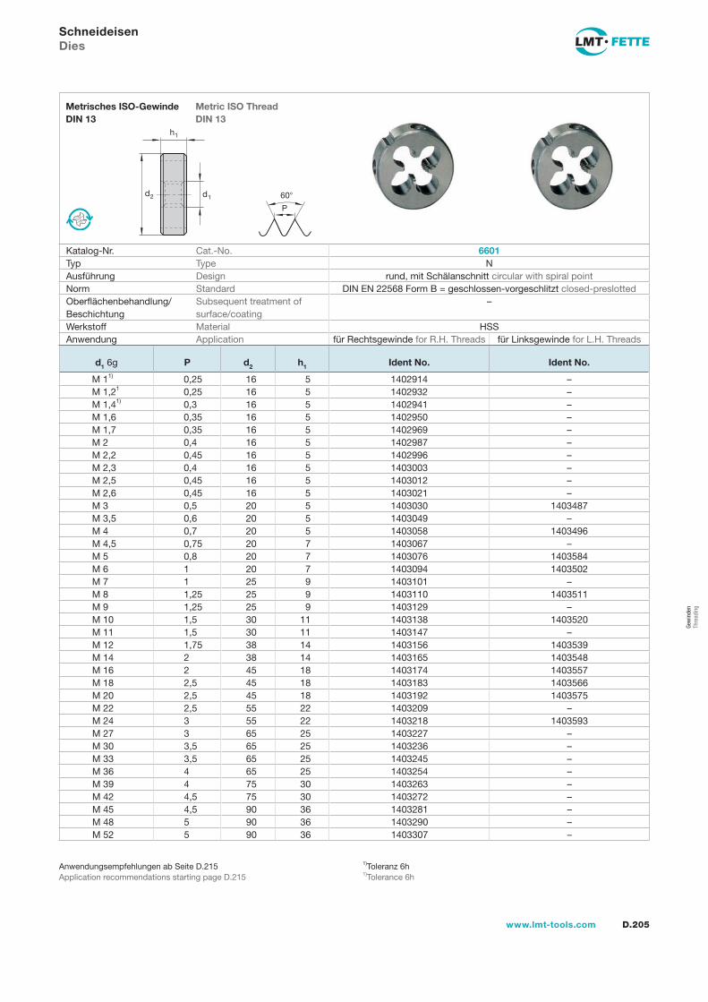
d2 d1
h1
60
P
D.205www.lmt-tools.com
Metric ISO ThreadDIN 13
Metrisches ISO-GewindeDIN 13
1)Toleranz 6h1)Tolerance 6h
Anwendungsempfehlungen ab Seite D.215Application recommendations starting page D.215
SchneideisenDies
Katalog-Nr. Cat.-No. 6601Typ Type NAusführung Design rund, mit Schälanschnitt circular with spiral pointNorm Standard DIN EN 22568 Form B = geschlossen-vorgeschlitzt closed-preslottedOberflächenbehandlung/Beschichtung
Subsequent treatment of surface/coating
–
Werkstoff Material HSSAnwendung Application für Rechtsgewinde for R.H. Threads für Linksgewinde for L.H. Threads
d1 6g P d2 h1 Ident No. Ident No.
M 11) 0,25 16 5 1402914 –M 1,21 0,25 16 5 1402932 –M 1,41) 0,3 16 5 1402941 –M 1,6 0,35 16 5 1402950 –M 1,7 0,35 16 5 1402969 –M 2 0,4 16 5 1402987 –M 2,2 0,45 16 5 1402996 –M 2,3 0,4 16 5 1403003 –M 2,5 0,45 16 5 1403012 –M 2,6 0,45 16 5 1403021 –M 3 0,5 20 5 1403030 1403487M 3,5 0,6 20 5 1403049 –M 4 0,7 20 5 1403058 1403496M 4,5 0,75 20 7 1403067 –M 5 0,8 20 7 1403076 1403584M 6 1 20 7 1403094 1403502M 7 1 25 9 1403101 –M 8 1,25 25 9 1403110 1403511M 9 1,25 25 9 1403129 –M 10 1,5 30 11 1403138 1403520M 11 1,5 30 11 1403147 –M 12 1,75 38 14 1403156 1403539M 14 2 38 14 1403165 1403548M 16 2 45 18 1403174 1403557M 18 2,5 45 18 1403183 1403566M 20 2,5 45 18 1403192 1403575M 22 2,5 55 22 1403209 –M 24 3 55 22 1403218 1403593M 27 3 65 25 1403227 –M 30 3,5 65 25 1403236 –M 33 3,5 65 25 1403245 –M 36 4 65 25 1403254 –M 39 4 75 30 1403263 –M 42 4,5 75 30 1403272 –M 45 4,5 90 36 1403281 –M 48 5 90 36 1403290 –M 52 5 90 36 1403307 –
Gew
inde
n Th
read
ing
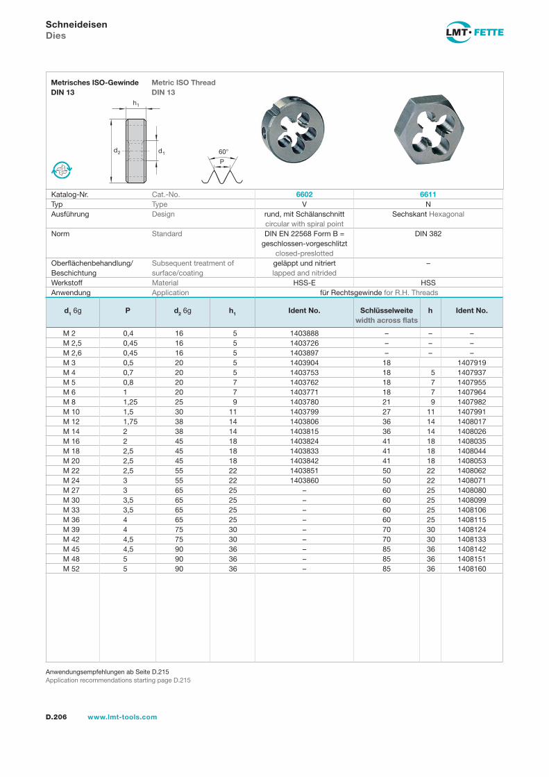
d2 d1
h1
60
P
D.206 www.lmt-tools.com
Metric ISO ThreadDIN 13
Metrisches ISO-GewindeDIN 13
Anwendungsempfehlungen ab Seite D.215Application recommendations starting page D.215
SchneideisenDies
Katalog-Nr. Cat.-No. 6602 6611Typ Type V NAusführung Design rund, mit Schälanschnitt
circular with spiral pointSechskant Hexagonal
Norm Standard DIN EN 22568 Form B = geschlossen-vorgeschlitzt
closed-preslotted
DIN 382
Oberflächenbehandlung/Beschichtung
Subsequent treatment of surface/coating
geläppt und nitriert lapped and nitrided
–
Werkstoff Material HSS-E HSSAnwendung Application für Rechtsgewinde for R.H. Threads
d1 6g P d2 6g h1 Ident No. Schlüsselweite width across flats
h Ident No.
M 2 0,4 16 5 1403888 – – –M 2,5 0,45 16 5 1403726 – – –M 2,6 0,45 16 5 1403897 – – –M 3 0,5 20 5 1403904 18 1407919M 4 0,7 20 5 1403753 18 5 1407937M 5 0,8 20 7 1403762 18 7 1407955M 6 1 20 7 1403771 18 7 1407964M 8 1,25 25 9 1403780 21 9 1407982M 10 1,5 30 11 1403799 27 11 1407991M 12 1,75 38 14 1403806 36 14 1408017M 14 2 38 14 1403815 36 14 1408026M 16 2 45 18 1403824 41 18 1408035M 18 2,5 45 18 1403833 41 18 1408044M 20 2,5 45 18 1403842 41 18 1408053M 22 2,5 55 22 1403851 50 22 1408062M 24 3 55 22 1403860 50 22 1408071M 27 3 65 25 – 60 25 1408080M 30 3,5 65 25 – 60 25 1408099M 33 3,5 65 25 – 60 25 1408106M 36 4 65 25 – 60 25 1408115M 39 4 75 30 – 70 30 1408124M 42 4,5 75 30 – 70 30 1408133M 45 4,5 90 36 – 85 36 1408142M 48 5 90 36 – 85 36 1408151M 52 5 90 36 – 85 36 1408160
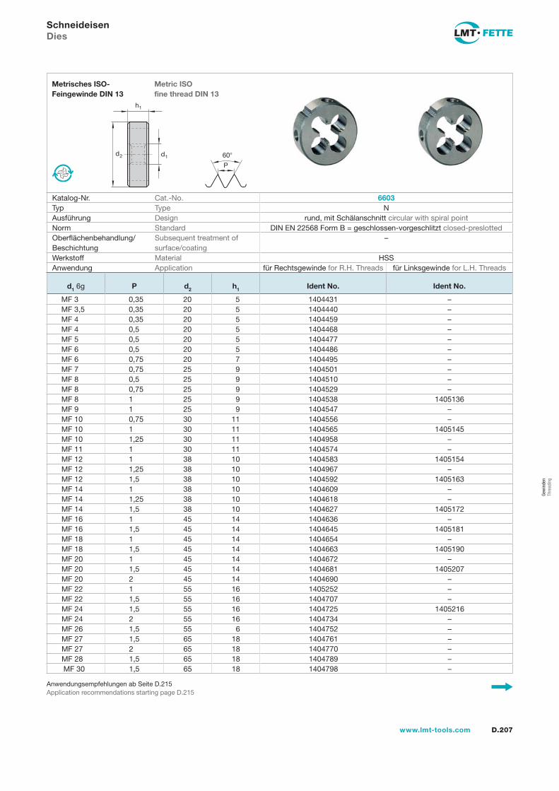
d2 d1
h1
60
P
D.207www.lmt-tools.com
Metric ISO fine thread DIN 13
Metrisches ISO- Feingewinde DIN 13
Anwendungsempfehlungen ab Seite D.215Application recommendations starting page D.215
SchneideisenDies
Katalog-Nr. Cat.-No. 6603Typ Type NAusführung Design rund, mit Schälanschnitt circular with spiral pointNorm Standard DIN EN 22568 Form B = geschlossen-vorgeschlitzt closed-preslottedOberflächenbehandlung/Beschichtung
Subsequent treatment of surface/coating
–
Werkstoff Material HSSAnwendung Application für Rechtsgewinde for R.H. Threads für Linksgewinde for L.H. Threads
d1 6g P d2 h1 Ident No. Ident No.
MF 3 0,35 20 5 1404431 –MF 3,5 0,35 20 5 1404440 –MF 4 0,35 20 5 1404459 –MF 4 0,5 20 5 1404468 –MF 5 0,5 20 5 1404477 –MF 6 0,5 20 5 1404486 –MF 6 0,75 20 7 1404495 –MF 7 0,75 25 9 1404501 –MF 8 0,5 25 9 1404510 –MF 8 0,75 25 9 1404529 –MF 8 1 25 9 1404538 1405136MF 9 1 25 9 1404547 –MF 10 0,75 30 11 1404556 –MF 10 1 30 11 1404565 1405145MF 10 1,25 30 11 1404958 –MF 11 1 30 11 1404574 –MF 12 1 38 10 1404583 1405154MF 12 1,25 38 10 1404967 –MF 12 1,5 38 10 1404592 1405163MF 14 1 38 10 1404609 –MF 14 1,25 38 10 1404618 –MF 14 1,5 38 10 1404627 1405172MF 16 1 45 14 1404636 –MF 16 1,5 45 14 1404645 1405181MF 18 1 45 14 1404654 –MF 18 1,5 45 14 1404663 1405190MF 20 1 45 14 1404672 –MF 20 1,5 45 14 1404681 1405207MF 20 2 45 14 1404690 –MF 22 1 55 16 1405252 –MF 22 1,5 55 16 1404707 –MF 24 1,5 55 16 1404725 1405216MF 24 2 55 16 1404734 –MF 26 1,5 55 6 1404752 –MF 27 1,5 65 18 1404761 –MF 27 2 65 18 1404770 –MF 28 1,5 65 18 1404789 –MF 30 1,5 65 18 1404798 –
Gew
inde
n Th
read
ing
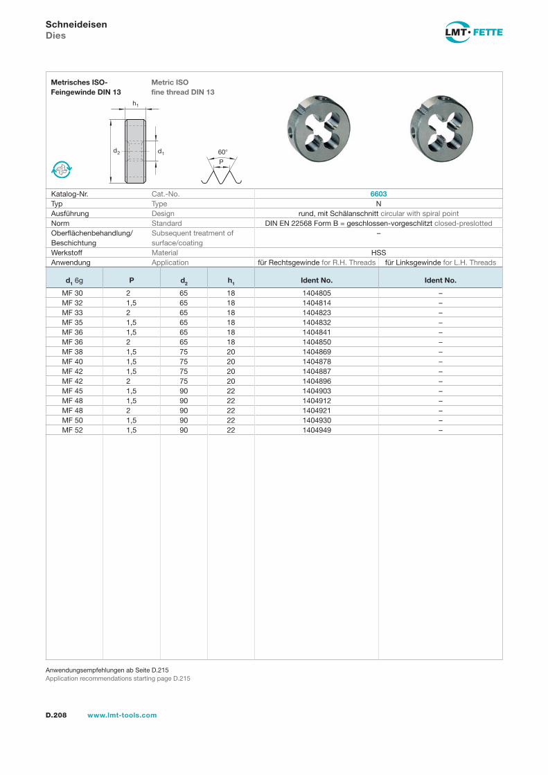
D.208 www.lmt-tools.com
Anwendungsempfehlungen ab Seite D.215Application recommendations starting page D.215
SchneideisenDies
d2 d1
h1
60
P
Metric ISO fine thread DIN 13
Metrisches ISO- Feingewinde DIN 13
Katalog-Nr. Cat.-No. 6603Typ Type NAusführung Design rund, mit Schälanschnitt circular with spiral pointNorm Standard DIN EN 22568 Form B = geschlossen-vorgeschlitzt closed-preslottedOberflächenbehandlung/Beschichtung
Subsequent treatment of surface/coating
–
Werkstoff Material HSSAnwendung Application für Rechtsgewinde for R.H. Threads für Linksgewinde for L.H. Threads
d1 6g P d2 h1 Ident No. Ident No.
MF 30 2 65 18 1404805 –MF 32 1,5 65 18 1404814 –MF 33 2 65 18 1404823 –MF 35 1,5 65 18 1404832 –MF 36 1,5 65 18 1404841 –MF 36 2 65 18 1404850 –MF 38 1,5 75 20 1404869 –MF 40 1,5 75 20 1404878 –MF 42 1,5 75 20 1404887 –MF 42 2 75 20 1404896 –MF 45 1,5 90 22 1404903 –MF 48 1,5 90 22 1404912 –MF 48 2 90 22 1404921 –MF 50 1,5 90 22 1404930 –MF 52 1,5 90 22 1404949 –
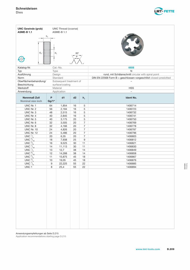
d2 d1
h1
60
P
D.209www.lmt-tools.com
UNC Thread (coarse)ASME-B 1.1
UNC Gewinde (grob)ASME-B 1.1
Anwendungsempfehlungen ab Seite D.215Application recommendations starting page D.215
SchneideisenDies
Katalog-Nr. Cat.-No. 6608Typ Type NAusführung Design rund, mit Schälanschnitt circular with spiral pointNorm Standard DIN EN 22568 Form B = geschlossen-vorgeschlitzt closed-preslottedOberflächenbehandlung/Beschichtung
Subsequent treatment of surface/coating
–
Werkstoff Material HSSAnwendung Application –
Nennmaß Zoll Nominal size inch
PGg/1“
d1 d2 h1 Ident No.
UNC Nr. 1 64 1,854 16 5 1406714UNC Nr. 2 56 2,184 16 5 1406723UNC Nr. 3 48 2,515 16 5 1406732UNC Nr. 4 40 2,845 16 5 1406741UNC Nr. 5 40 3,175 20 5 1406750UNC Nr. 6 32 3,505 20 7 1406769UNC Nr. 8 32 4,166 20 7 1406778UNC Nr. 10 24 4,826 20 7 1406787UNC Nr. 12 24 5,486 20 7 1406796UNC 1/4 20 6,35 20 7 1406803UNC 5/16 18 7,938 25 9 1406812UNC 3/8 16 9,525 30 11 1406821UNC 7/16 14 11,113 30 11 1406830UNC 1/2 13 12,7 38 14 1406849UNC 9/16 12 14,288 38 14 1406858UNC 5/8 11 15,875 45 18 1406867UNC 3/4 10 19,05 45 18 1406876UNC 7/8 9 22,225 55 22 1406885UNC 1 8 25,4 55 22 1406894
Gew
inde
n Th
read
ing
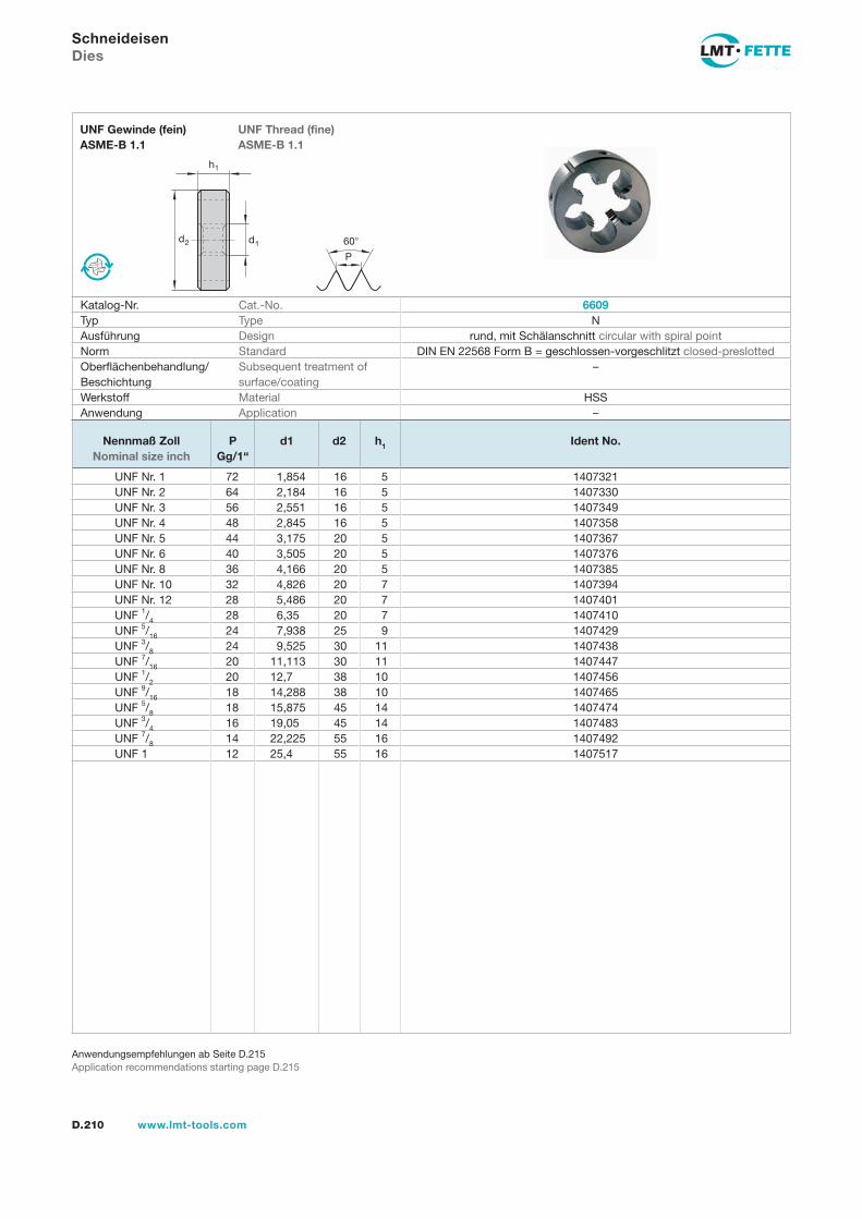
d2 d1
h1
60
P
D.210 www.lmt-tools.com
UNF Thread (fine)ASME-B 1.1
UNF Gewinde (fein)ASME-B 1.1
Anwendungsempfehlungen ab Seite D.215Application recommendations starting page D.215
SchneideisenDies
Katalog-Nr. Cat.-No. 6609Typ Type NAusführung Design rund, mit Schälanschnitt circular with spiral pointNorm Standard DIN EN 22568 Form B = geschlossen-vorgeschlitzt closed-preslottedOberflächenbehandlung/Beschichtung
Subsequent treatment of surface/coating
–
Werkstoff Material HSSAnwendung Application –
Nennmaß Zoll Nominal size inch
PGg/1“
d1 d2 h1 Ident No.
UNF Nr. 1 72 1,854 16 5 1407321UNF Nr. 2 64 2,184 16 5 1407330UNF Nr. 3 56 2,551 16 5 1407349UNF Nr. 4 48 2,845 16 5 1407358UNF Nr. 5 44 3,175 20 5 1407367UNF Nr. 6 40 3,505 20 5 1407376UNF Nr. 8 36 4,166 20 5 1407385UNF Nr. 10 32 4,826 20 7 1407394UNF Nr. 12 28 5,486 20 7 1407401UNF 1/4 28 6,35 20 7 1407410UNF 5/16 24 7,938 25 9 1407429UNF 3/8 24 9,525 30 11 1407438UNF 7/16 20 11,113 30 11 1407447UNF 1/2 20 12,7 38 10 1407456UNF 9/16 18 14,288 38 10 1407465UNF 5/8 18 15,875 45 14 1407474UNF 3/4 16 19,05 45 14 1407483UNF 7/8 14 22,225 55 16 1407492UNF 1 12 25,4 55 16 1407517
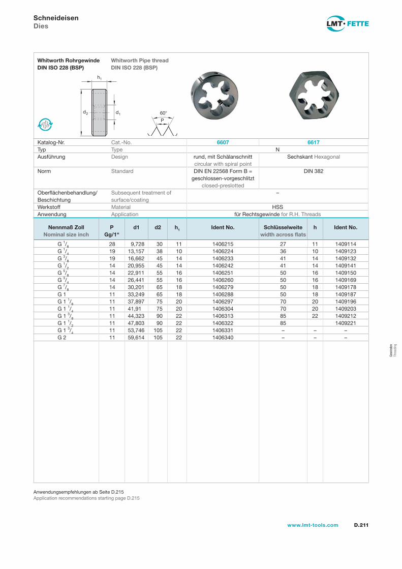
d2 d1
h1
60
P
D.211www.lmt-tools.com
Whitworth Pipe threadDIN ISO 228 (BSP)
Whitworth RohrgewindeDIN ISO 228 (BSP)
Anwendungsempfehlungen ab Seite D.215Application recommendations starting page D.215
SchneideisenDies
Katalog-Nr. Cat.-No. 6607 6617Typ Type NAusführung Design rund, mit Schälanschnitt
circular with spiral pointSechskant Hexagonal
Norm Standard DIN EN 22568 Form B = geschlossen-vorgeschlitzt
closed-preslotted
DIN 382
Oberflächenbehandlung/Beschichtung
Subsequent treatment of surface/coating
–
Werkstoff Material HSSAnwendung Application für Rechtsgewinde for R.H. Threads
Nennmaß Zoll Nominal size inch
PGg/1“
d1 d2 h1 Ident No. Schlüsselweite width across flats
h Ident No.
G 1/8 28 9,728 30 11 1406215 27 11 1409114G 1/4 19 13,157 38 10 1406224 36 10 1409123G 3/8 19 16,662 45 14 1406233 41 14 1409132G 1/2 14 20,955 45 14 1406242 41 14 1409141G 5/8 14 22,911 55 16 1406251 50 16 1409150G 3/4 14 26,441 55 16 1406260 50 16 1409169G 7/8 14 30,201 65 18 1406279 50 18 1409178G 1 11 33,249 65 18 1406288 50 18 1409187G 1 1/8 11 37,897 75 20 1406297 70 20 1409196G 1 1/4 11 41,91 75 20 1406304 70 20 1409203G 1 3/8 11 44,323 90 22 1406313 85 22 1409212G 1 1/2 11 47,803 90 22 1406322 85 1409221G 1 3/4 11 53,746 105 22 1406331 – – –G 2 11 59,614 105 22 1406340 – – –
Gew
inde
n Th
read
ing
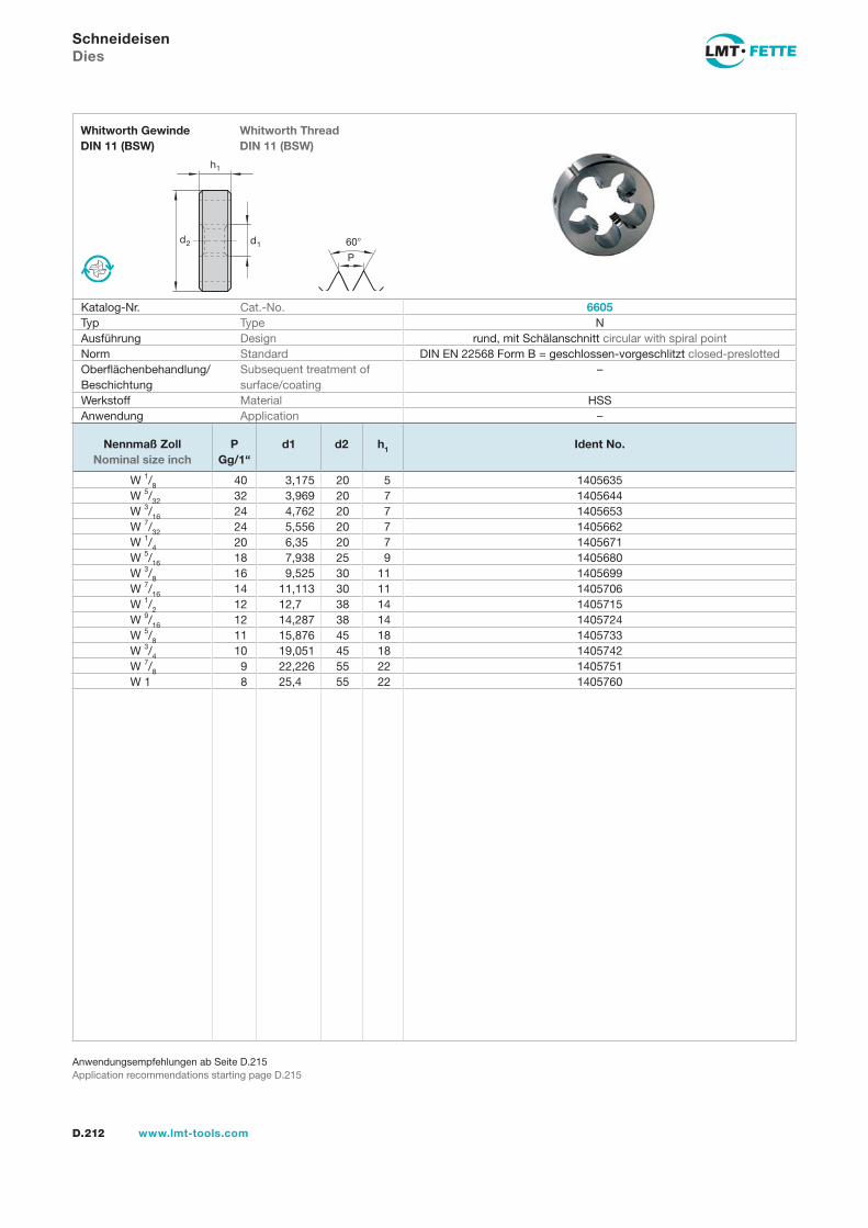
d2 d1
h1
60
P
D.212 www.lmt-tools.com
Whitworth ThreadDIN 11 (BSW)
Whitworth GewindeDIN 11 (BSW)
Anwendungsempfehlungen ab Seite D.215Application recommendations starting page D.215
SchneideisenDies
Katalog-Nr. Cat.-No. 6605Typ Type NAusführung Design rund, mit Schälanschnitt circular with spiral pointNorm Standard DIN EN 22568 Form B = geschlossen-vorgeschlitzt closed-preslottedOberflächenbehandlung/Beschichtung
Subsequent treatment of surface/coating
–
Werkstoff Material HSSAnwendung Application –
Nennmaß Zoll Nominal size inch
PGg/1“
d1 d2 h1 Ident No.
W 1/8 40 3,175 20 5 1405635W 5/32 32 3,969 20 7 1405644W 3/16 24 4,762 20 7 1405653W 7/32 24 5,556 20 7 1405662W 1/4 20 6,35 20 7 1405671W 5/16 18 7,938 25 9 1405680W 3/8 16 9,525 30 11 1405699W 7/16 14 11,113 30 11 1405706W 1/2 12 12,7 38 14 1405715W 9/16 12 14,287 38 14 1405724W 5/8 11 15,876 45 18 1405733W 3/4 10 19,051 45 18 1405742W 7/8 9 22,226 55 22 1405751W 1 8 25,4 55 22 1405760
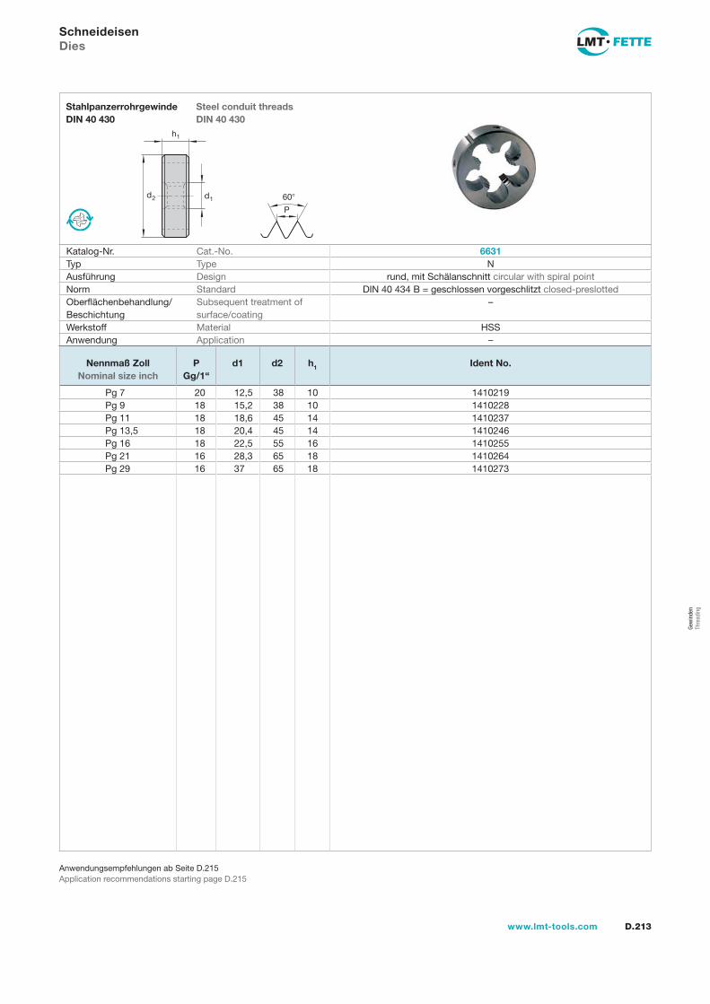
d2 d1
h1
60
P
D.213www.lmt-tools.com
Steel conduit threadsDIN 40 430
StahlpanzerrohrgewindeDIN 40 430
Anwendungsempfehlungen ab Seite D.215Application recommendations starting page D.215
SchneideisenDies
Katalog-Nr. Cat.-No. 6631Typ Type NAusführung Design rund, mit Schälanschnitt circular with spiral pointNorm Standard DIN 40 434 B = geschlossen vorgeschlitzt closed-preslottedOberflächenbehandlung/Beschichtung
Subsequent treatment of surface/coating
–
Werkstoff Material HSSAnwendung Application –
Nennmaß Zoll Nominal size inch
PGg/1“
d1 d2 h1 Ident No.
Pg 7 20 12,5 38 10 1410219Pg 9 18 15,2 38 10 1410228Pg 11 18 18,6 45 14 1410237Pg 13,5 18 20,4 45 14 1410246Pg 16 18 22,5 55 16 1410255Pg 21 16 28,3 65 18 1410264Pg 29 16 37 65 18 1410273
Gew
inde
n Th
read
ing
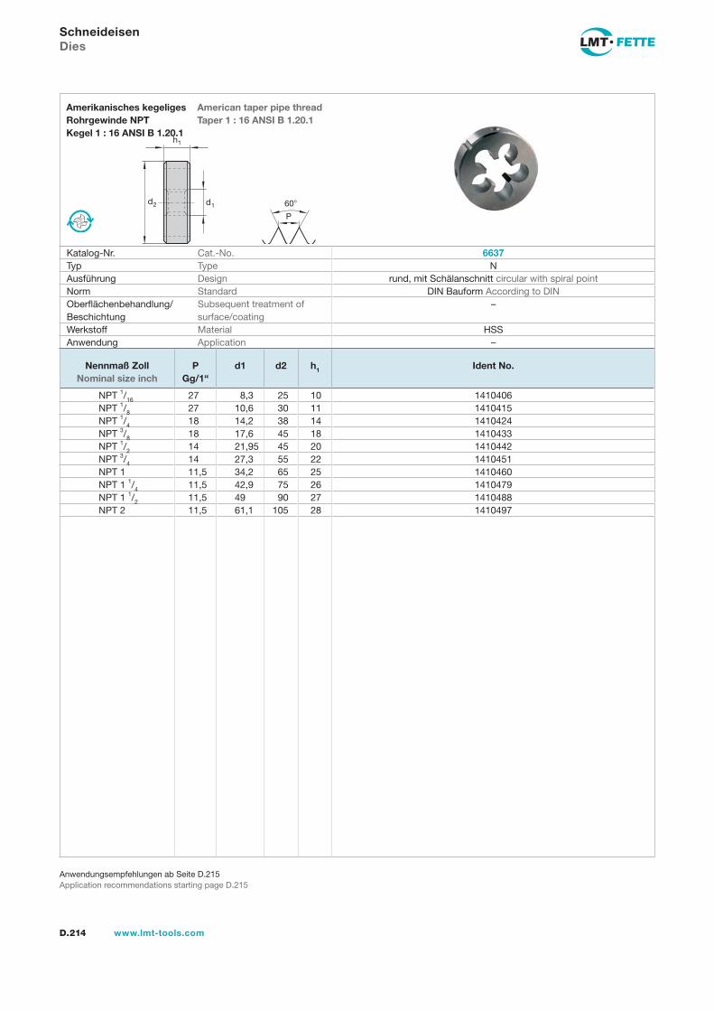
d2 d1
h1
60
P
D.214 www.lmt-tools.com
American taper pipe threadTaper 1 : 16 ANSI B 1.20.1
Amerikanisches kegeligesRohrgewinde NPT Kegel 1 : 16 ANSI B 1.20.1
Anwendungsempfehlungen ab Seite D.215Application recommendations starting page D.215
SchneideisenDies
Katalog-Nr. Cat.-No. 6637Typ Type NAusführung Design rund, mit Schälanschnitt circular with spiral pointNorm Standard DIN Bauform According to DINOberflächenbehandlung/Beschichtung
Subsequent treatment of surface/coating
–
Werkstoff Material HSSAnwendung Application –
Nennmaß Zoll Nominal size inch
PGg/1“
d1 d2 h1 Ident No.
NPT 1/16 27 8,3 25 10 1410406NPT 1/8 27 10,6 30 11 1410415NPT 1/4 18 14,2 38 14 1410424NPT 3/8 18 17,6 45 18 1410433NPT 1/2 14 21,95 45 20 1410442NPT 3/4 14 27,3 55 22 1410451NPT 1 11,5 34,2 65 25 1410460NPT 1 1/4 11,5 42,9 75 26 1410479NPT 1 1/2 11,5 49 90 27 1410488NPT 2 11,5 61,1 105 28 1410497
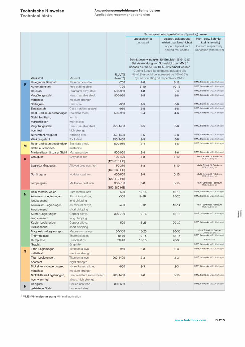
D.215www.lmt-tools.com
Rm/UTS(N/mm2)
Unlegierter Baustahl Plain carbon steel
Automatenstahl Free cutting steel
Baustahl Structural alloy steel
Vergütungsstahl, Heat-treatable steel,
mittelfest medium strength
Stahlguss Cast steel
Einsatzstahl Case hardening steel
Rost- und säurebeständiger Stainless steel,
Stahl, ferritisch, ferritic,
martensitisch martensitic
Vergütungsstahl, Heat-treatable steel,
hochfest high strength
Nitrierstahl, vergütet Nitriding steel
Werkzeugstahl Tool steel
Rost- und säurebeständiger Stainless steel,
Stahl, austenitisch austenitic
Martensitaushärtbarer Stahl Maraging steel
Grauguss Grey cast iron
Legierter Grauguss Alloyed grey cast iron
Sphäroguss Nodular cast iron
Temperguss Malleable cast iron
Rein-Metalle, weich Pure metals, soft
Aluminium-Legierungen, Aluminium alloys,
langspanend long chipping
Aluminium-Legierungen, Aluminium alloys,
kurzspanend short chipping
Kupfer-Legierungen, Copper alloys,
langspanend long chipping
Kupfer-Legierungen, Copper alloys,
kurzspanend short chipping
Magnesium-Legierungen Magnesium alloys
Thermoplaste Thermoplastics
Duroplaste Duroplastics
Graphit Graphite
Titan-Legierungen, Titanium alloys,
mittelfest medium strength
Titan-Legierungen, Titanium alloys,
hochfest hight strength
Nickelbasis-Legierungen, Nickel based alloys,
mittelfest medium strength
Nickel-Basis-Legierungen, Heat resistant nickel based
hochwarmfest alloys, high strength
Hartguss Chilled cast iron
gehärteter Stahl hardened steel
Werkstoff Material -700
-700
500-950
500-950
-950
-950
500-950
950-1400
950-1400
950-1400
500-950
500-950
100-400
(120-310 HB)
150-250
(160-230 HB)
400-800
(120-310 HB)
350-700
(150-280 HB)
-500
-550
-400
300-700
-500
160-300
40-70
20-40
-950
900-1400
-950
900-1400
300-600
4-8
6-10
4-8
2-5
2-5
2-5
2-4
2-5
2-5
2-5
2-4
2-4
3-8
3-8
3-8
3-8
10-15
2-18
8-12
10-16
15-25
15-25
10-15
10-15
2-3
2-3
2-3
2-6
–
8-12
10-15
8-12
5-8
5-8
5-8
4-6
5-8
5-8
5-8
4-6
4-6
5-10
5-10
5-10
5-10
12-16
15-25
10-14
12-18
20-30
20-30
12-16
20-30
2-3
2-3
2-3
6-10
–
Anwendungsempfehlungen Schneideisen Application recommendations dies
1) MMS-Minimalschmierung Minimal lubrication
Schnittgeschwindigkeit/Cutting Speed vc(m/min)
Schnittgeschwindigkeit für Emulsion (8%-12%) Bei Verwendung von Schneidöl bzw. MMS1)
können die Werte um 10%-20% erhöht werdenCutting Speed for diffracted solvable oils
(8%-12%) could be increased by 10%-20% by use of cutting oil respectively MMS1)
Kühl- bzw. Schmier-mittel (alternativ)
Coolant respectively lubrication (alternative)
geläppt, geläppt und nitriert bzw. beschichtet
lapped, lapped and nitrited res. coated
unbeschichtetuncoated
MMS, Schneidöl MQL, Cutting oil
MMS, Schneidöl MQL, Cutting oil
MMS, Schneidöl MQL, Cutting oil
MMS, Schneidöl MQL, Cutting oil
MMS, Schneidöl MQL, Cutting oil
MMS, Schneidöl MQL, Cutting oil
MMS, Schneidöl MQL, Cutting oil
MMS, Schneidöl MQL, Cutting oil
MMS, Schneidöl MQL, Cutting oil
MMS, Schneidöl MQL, Cutting oil
MMS, Schneidöl MQL, Cutting oil
MMS, Schneidöl MQL, Cutting oil
MMS, Schneidöl, PetroleumMQL, Cutting oil
MMS, Schneidöl, PetroleumMQL, Cutting oil
MMS, Schneidöl, PetroleumMQL, Cutting oil
MMS, Schneidöl, PetroleumMQL, Cutting oil
MMS, Schneidöl MQL, Cutting oil
MMS, Schneidöl MQL, Cutting oil
MMS, Schneidöl, PetroleumMQL, Cutting oil
MMS, Schneidöl MQL, Cutting oil
MMS, Schneidöl MQL, Cutting oil
MMS, Schneidöl, Trocken Cutting oil, dry
MMS, Schneidöl MQL, Cutting oil
Trocken Dry
MMS, Schneidöl MQL, Cutting oil
MMS, Schneidöl MQL, Cutting oil
MMS, Schneidöl MQL, Cutting oil
MMS, Schneidöl MQL, Cutting oil
MMS, Schneidöl MQL, Cutting oil
MMS, Schneidöl MQL, Cutting oil
Technische Hinweise Technical hints
P
M
K
N
S
H
Gew
inde
n Th
read
ing
www.lmt-tools.comA.D.216
Gewinde-RollsystemeThread Rolling Systems

D.217www.lmt-tools.com
Gewinde-RollsystemeThread rolling systems
D.218 Das FETTE-Standardprogramm The FETTE standard program
D.222 Rollbeispiele Rolling example D.225 Axial-Gewinde-Rollköpfe Axial thread rolling headsD.225 Auswahl der Gewinde-Rollkopfgrößen nach Gewindeabmessungen Selection of thread rolling head sizes according to thread dimensionsD.226 F1C1, K1C1D.230 F2C2, K2C2D.234 F3C2, K3C2 D.239 Radial-Gewinde Rollköpfe Radial type thread rolling headsD.240 Type E und Type EWD.241 EW10A00 - EW23A00D.245 Gewinderollen Thread rolls D.253 Tangential-Gewinde-Rollköpfe Tangential thread rolling headsD.253 T120F, T160F, T220F, T350FD.257 Gewinderollen Thread rollsD.280 Einstelllehren Setting gauge D.282 Bestellformular Ordering form
Gew
inde
rolle
n Th
read
Rol
ling
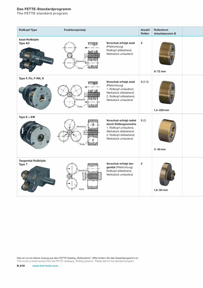
D.218 www.lmt-tools.com
Das FETTE-StandardprogrammThe FETTE standard program
Axial-RollköpfeType AC
Arbeitsbereich Ø
2
Rollkopf-Type Funktionsprinzip
3 (2-6)
3 (2)
2
Vorschub erfolgt axial (Pfeilrichtung) Rollkopf stillstehend, Werkstück umlaufend
Vorschub erfolgt axial (Pfeilrichtung) 1. Rollkopf umlaufend, Werkstück stillstehend2. Rollkopf stillstehend, Werkstück umlaufend
Vorschub erfolgt radial durch Rollengeometrie 1. Rollkopf umlaufend, Werkstück stillstehend2. Rollkopf stillstehend, Werkstück umlaufend
Vorschub erfolgt tan-gential (Pfeilrichtung) Rollkopf stillstehend, Werkstück umlaufend
Werkstück
Rolle
Werkstück
Rolle
Werkstück
Rolle
Werkstück
Rolle
Type F, FU, F-RN, K
Type E + EW
Tangential-RollköpfeType T
RollenformAnzahl Rollen
1,4-230 mm
8-72 mm
3-45 mm
1,6-64 mm
Dies ist nur ein kleiner Auszug aus dem FETTE-Katalog „Rollsysteme“. Bitte fordern Sie das Gesamtprogramm an.This is only a small excerpt from the FETTE catalogue „Rolling systems“. Please ask for the standard program.
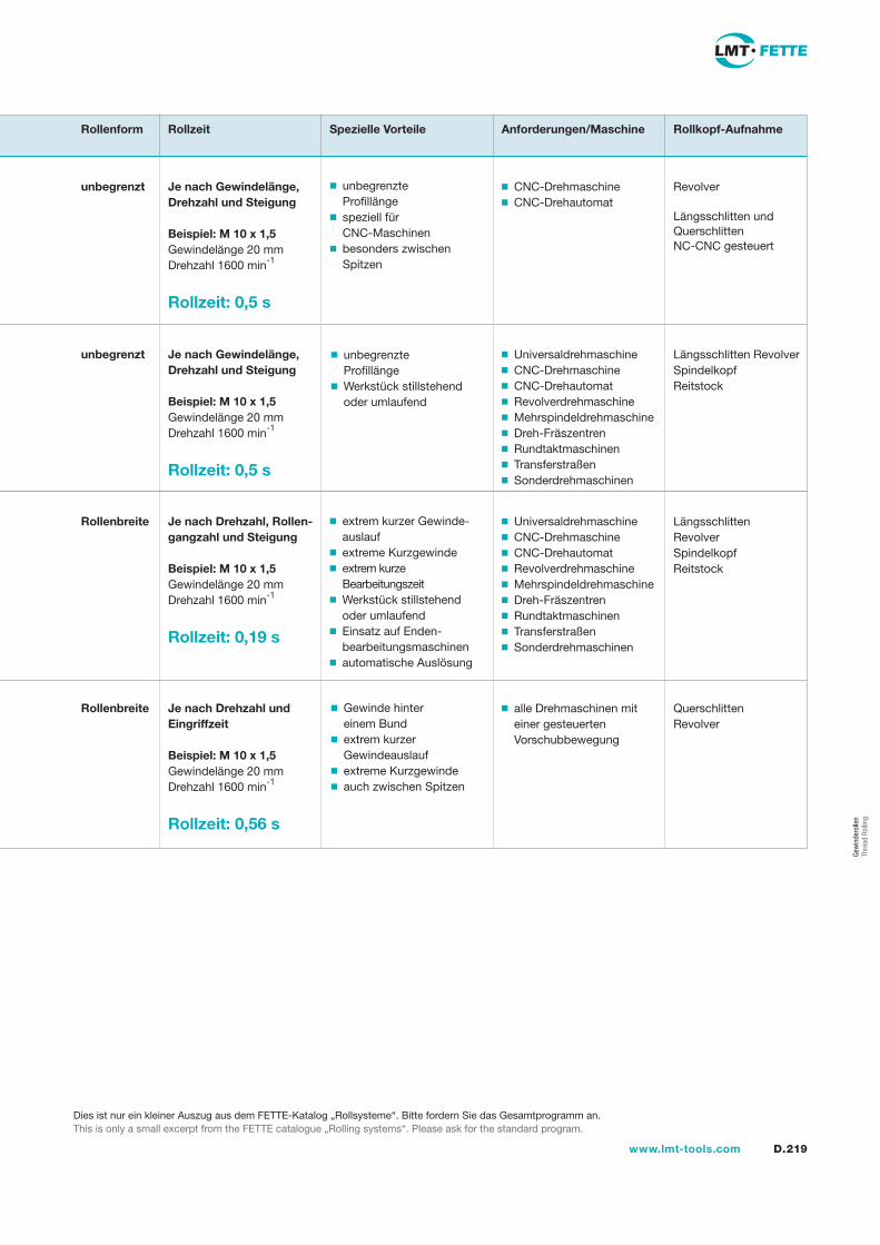
D.219www.lmt-tools.com
CNC-Drehmaschine CNC-Drehautomat
Universaldrehmaschine CNC-Drehmaschine CNC-Drehautomat Revolverdrehmaschine Mehrspindeldrehmaschine Dreh-Fräszentren Rundtaktmaschinen Transferstraßen Sonderdrehmaschinen
Universaldrehmaschine CNC-Drehmaschine CNC-Drehautomat Revolverdrehmaschine Mehrspindeldrehmaschine Dreh-Fräszentren Rundtaktmaschinen Transferstraßen Sonderdrehmaschinen
alle Drehmaschinen mit einer gesteuerten Vorschubbewegung
Revolver
Längsschlitten und Querschlitten NC-CNC gesteuert
Längsschlitten Revolver Spindelkopf Reitstock
Längsschlitten Revolver Spindelkopf Reitstock
QuerschlittenRevolver
Je nach Gewindelänge, Drehzahl und Steigung
Beispiel: M 10 x 1,5Gewindelänge 20 mmDrehzahl 1600 min-1
Rollzeit: 0,5 s
unbegrenzt
Je nach Gewindelänge, Drehzahl und Steigung
Beispiel: M 10 x 1,5Gewindelänge 20 mmDrehzahl 1600 min-1
Rollzeit: 0,5 s
unbegrenzt
Je nach Drehzahl, Rollen-gangzahl und Steigung
Beispiel: M 10 x 1,5Gewindelänge 20 mmDrehzahl 1600 min-1
Rollzeit: 0,19 s
Rollenbreite
Je nach Drehzahl und Eingriffzeit
Beispiel: M 10 x 1,5Gewindelänge 20 mmDrehzahl 1600 min-1
Rollzeit: 0,56 s
Rollenbreite
Rollenform Rollzeit Spezielle Vorteile Anforderungen/Maschine Rollkopf-Aufnahme
unbegrenzte Profillängespeziell für CNC-Maschinenbesonders zwischen Spitzen
unbegrenzte ProfillängeWerkstück stillstehend oder umlaufend
extrem kurzer Gewinde-auslaufextreme Kurzgewindeextrem kurze BearbeitungszeitWerkstück stillstehend oder umlaufendEinsatz auf Enden-bearbeitungsmaschinenautomatische Auslösung
Gewinde hinter einem Bundextrem kurzer Gewindeauslaufextreme Kurzgewindeauch zwischen Spitzen
Gew
inde
rolle
n Th
read
Rol
ling
Dies ist nur ein kleiner Auszug aus dem FETTE-Katalog „Rollsysteme“. Bitte fordern Sie das Gesamtprogramm an.This is only a small excerpt from the FETTE catalogue „Rolling systems“. Please ask for the standard program.
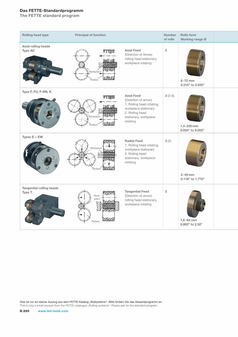
D.220 www.lmt-tools.com
Das FETTE-StandardprogrammThe FETTE standard program
Working range Ø
2
Rolling head type Principal of function
3 (2-6)
3 (2)
2
Axial Feed(Direction of Arrow) rolling head stationary, workpiece rotating
Axial Feed(Direction of arrow) 1. Rolling head rotating, workpiece stationary2. Rolling head stationary, workpiece rotating
Radial Feed 1. Rolling head rotating,workpiece stationary2. Rolling head stationary, workpiece rotating
Tangential Feed(Direction of arrow) rolling head stationary, workpiece rotating
Workpiece
Rollers
Workpiece
Rollers
Workpiece
Rollers
Rollers
Type F, FU, F-RN, K
Types E + EW
Tangential rolling headsType T
Rolls formNumber of rolls
1,4-230 mm0.055” to 9.055”
8-72 mm0.315” to 2.835”
3-45 mm0.118” to 1.772”
1,6-64 mm0.063” to 2.52”
Axial rolling headsType AC
Work-piece
Dies ist nur ein kleiner Auszug aus dem FETTE-Katalog „Rollsysteme“. Bitte fordern Sie das Gesamtprogramm an.This is only a small excerpt from the FETTE catalogue „Rolling systems“. Please ask for the standard program.

D.221www.lmt-tools.com
unlimited Profile length specially
for CNC machines particularly between
peaks
unlimited Profile length workpiece stationary
or rotating
extremely short thread run-out extremely short thread extremely short machining
time workplace stationary
or rotating- use on end cutting machines automatic release
thread behind a collar extremely short thread
run out extremely short thread including between peaks
CNC latheCNC automatic lathe
universal latheCNC latheCNC automatic latheturret lathemultiple spindle latheturning/milling centersrevolving transfer machinestransfer linesspecial lathes
universal latheCNC latheCNC automatic latheturret lathemultiple spindle latheturning/milling centersrevolving transfer machinestransfer linesspecial lathes
all lathes with a controlled feed movement
Turret
Saddle-slide and cross-slide NC-CNC controlled
Saddle slide Turret Spindle head Tailstock
Saddle slide Turret Spindle head Tailstock
Cross SlideTurret
Depending on thread length, rotating speed and pitch
Example: M 10 x 1,5Thread lenght 20 mm, 0.787”Example: 3/8 x 16 UNCThread lenght .150”
Rotation speed 1600 min-1/RPM
Rolling time: 0,5 s
Unlimited
Depending on thread lenght, rotation speed and pitch
Example: M 10 x 1,5Thread lenght 20 mm, 0.787”Example: 3/8 x 16 UNCThread lenght .150”
Rotation speed 1600 min-1/RPM
Rolling time: 0,5 s
Unlimited
Depending on rotation speed, roller groovenumber and pitch
Example: M 10 x 1,5Thread lenght 20 mm, 0.787”Example: 3/8 x 16 UNCThread lenght .150”
Rotation speed 1600 min-1/RPM
Rolling time: 0,19 s
Rolls width
Depending on rotation speed and engagement time
Example: M 10 x 1,5Thread lenght 20 mm, 0.787”Example: 3/8 x 16 UNCThread lenght .150”
Rotation speed 1600 min-1/RPM
Rolling time: 0,56 s
Rolls width
Rolls form Rolling time Particular advantages Requirements/Machine Rolling head holder
Dies ist nur ein kleiner Auszug aus dem FETTE-Katalog „Rollsysteme“. Bitte fordern Sie das Gesamtprogramm an.This is only a small excerpt from the FETTE catalogue „Rolling systems“. Please ask for the standard program.
Gew
inde
rolle
n Th
read
Rol
ling
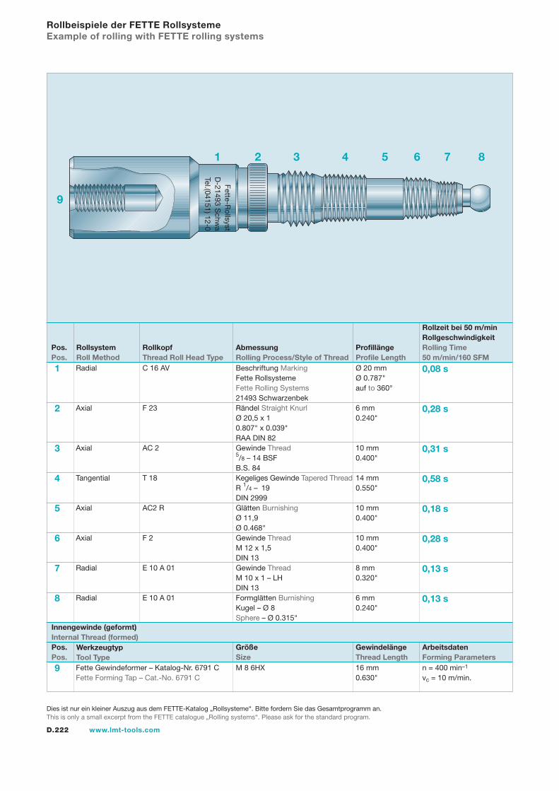
D.222 www.lmt-tools.com
Rollbeispiele der FETTE RollsystemeExample of rolling with FETTE rolling systems
9 Fette Gewindeformer – Katalog-Nr. 6791 C M 8 6HX 16 mm n = 400 min–1
Fette Forming Tap – Cat.-No. 6791 C 0.630" vc = 10 m/min.
Innengewinde (geformt) Internal Thread (formed)Pos.Pos.
WerkzeugtypTool Type
GewindelängeThread Length
ArbeitsdatenForming Parameters
GrößeSize
1 Radial C 16 AV Beschriftung Marking Ø 20 mm 0,08 s Fette Rollsysteme Ø 0.787" Fette Rolling Systems auf to 360° 21493 Schwarzenbek 2 Axial F 23 Rändel Straight Knurl 6 mm 0,28 s Ø 20,5 x 1 0.240" 0.807" x 0.039" RAA DIN 82 3 Axial AC 2 Gewinde Thread 10 mm 0,31 s 5/8 – 14 BSF 0.400" B.S. 84 4 Tangential T 18 Kegeliges Gewinde Tapered Thread 14 mm 0,58 s R 1/4 – 19 0.550" DIN 2999 5 Axial AC2 R Glätten Burnishing 10 mm 0,18 s Ø 11,9 0.400" Ø 0.468" 6 Axial F 2 Gewinde Thread 10 mm 0,28 s M 12 x 1,5 0.400" DIN 13 7 Radial E 10 A 01 Gewinde Thread 8 mm 0,13 s M 10 x 1 – LH 0.320" DIN 13 8 Radial E 10 A 01 Formglätten Burnishing 6 mm 0,13 s Kugel – Ø 8 0.240" Sphere – Ø 0.315"
Pos.Pos.
RollsystemRoll Method
RollkopfThread Roll Head Type
ProfillängeProfile Length
Rollzeit bei 50 m/minRollgeschwindigkeitRolling Time50 m/min/160 SFM
AbmessungRolling Process/Style of Thread
1
9
2 3 4 5 6 7 8
9
Fette-Rollsyst
D-21493 S
chwa
Tel.(04151) 12-0
Dies ist nur ein kleiner Auszug aus dem FETTE-Katalog „Rollsysteme“. Bitte fordern Sie das Gesamtprogramm an.This is only a small excerpt from the FETTE catalogue „Rolling systems“. Please ask for the standard program.
D.223www.lmt-tools.com
NotizenNotes
Gew
inde
rolle
n Th
read
Rol
ling
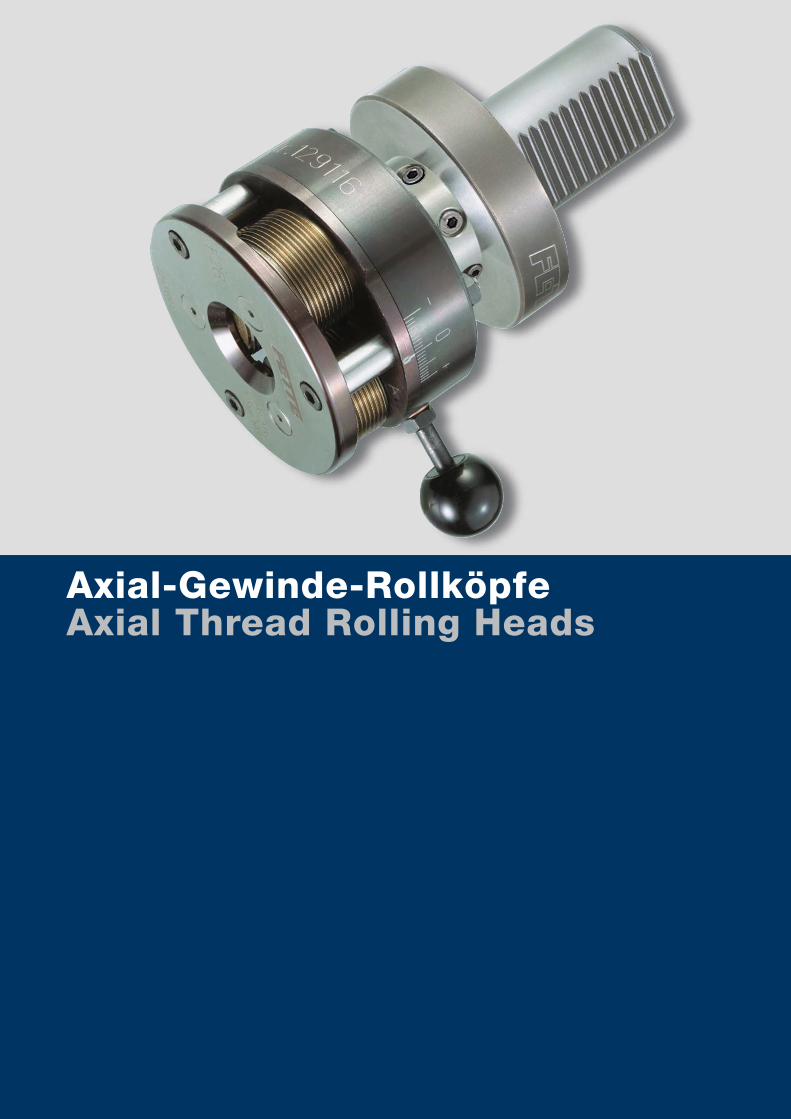
www.lmt-tools.comA.D.224
Axial-Gewinde-RollköpfeAxial Thread Rolling Heads
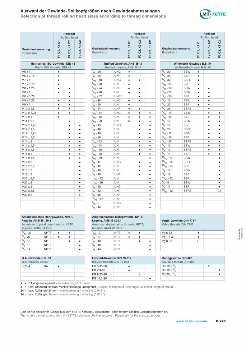
D.225www.lmt-tools.com
Auswahl der Gewinde-Rollkopfgrößen nach GewindeabmessungenSelection of thread rolling head sizes according to thread dimensions
Gewindeabmessungthread size
Rollkopf Rolling head
GewindeabmessungRolling head thread size
Rollkopf
GewindeabmessungRolling head thread size
Rollkopf
F1 C
1, K
1 C
1
F2 C
2, K
2 C
2
F3 C
2, K
3 C
2
F1 C
1, K
1 C
1
F2 C
2, K
2 C
2
F3 C
2, K
3 C
2
F1 C
1, K
1 C
1
F2 C
2, K
2 C
2
F3 C
2, K
3 C
2
Metrisches ISO-Gewinde, DIN 13Metric ISO threads, DIN 13
Unified-Gewinde, ANSI B1.1Unified threads, ANSI B1.1
Whitworth-Gewinde B.S. 84Whitworth-threads B.S. 84
M6 x 1 ● 1/4 - 20 UNC ● 1/4 - 20 BSW ●M6 x 0,75 ● 1/4 - 28 UNF ● 1/4 - 26 BSF ●M7 x 1 ● 5/16 - 18 UNC ● ● 1/4 - 32 BSFS ●M7 x 0,75 ● 5/16 - 20 UN ● 9/32 - 26 BSF ●M8 x 1,25 ● ● 5/16 - 24 UNF ● ● 5/16 - 18 BSW ● ●M8 x 1 ● ● 5/16 - 28 UN ● ● 5/16 - 20 BSW ● ●M8 x 0,75 ● 5/16 - 32 UNEF ● 5/16 - 26 BSF ● ●M9 x 1,25 ● ● 3/8 - 16 UNC ● ● 3/8 - 16 BSW ● ●M9 x 1 ● ● 3/8 - 20 UN ● 3/8 - 20 BSF ● ●M10 x 1,5 ● ● 3/8 - 24 UNF ● ● 3/8 - 26 BSFS ●M10 x 1,25 ● ● 7/16 - 14 UNC 14 ● ● 7/16 - 14 BSW ● ●M10 x 1 ● 7/16 - 16 UN ● ● ● 7/16 - 18 BSF ● ●M11 x 1,5 ● 7/16 - 20 UNF 14 ● ● 1/2 - 12 BSW ● ●M12 x 1,75 ● ● 1/2 - 13 UNC ● ● 1/2 - 16 BSF ● ●M12 x 1,5 ● ● 1/2 - 16 UN ● ● 1/2 - 20 BSFS ● ●M12 x 1,25 ● ● 1/2 - 18 UN ● ● 9/16 - 12 BSW ● ●M13 x 1,5 ● ● 1/2 - 20 UN ● ● 9/16 - 16 BSF ● ●M14 x 2 ● ● 9/16 - 12 UN ● ● 9/16 - 20 BSFS ● ●M14 x 1,5 ● ● 9/16 - 14 UN ● ● 5/8 - 11 BSW ● ●M15 x 1,5 ● ● 9/16 - 16 UN ● ● 5/8 - 13 BSFS ● ●M16 x 2 ● ● 9/16 - 18 UNF ● ● 5/8 - 14 BSF ● ●M16 x 1,5 ● ● 9/16 - 20 UN ● 11/16 - 11 BSW ●M17 x 2 ● 5/8 - 11 UNC ● ● 11/16 - 14 BSFS ●M18 x 2,5 ● 5/8 - 12 UN ● ● 11/16 - 16 BSF ●M18 x 2 ● 5/8 - 16 UN ● ● 3/4 - 10 BSW ●M19 x 2 ● 5/8 - 18 UNF ● ● 3/4 - 12 BSF ●M20 x 2,5 ● 11/16 - 12 UN ● 13/16 - 12 BSF ●M20 x 2 ● 11/16 - 16 UN ● 7/8 - 9 BSW ●M21 x 2 ● 3/4 - 10 UNC ● 7/8 - 11 BSF ●M22 x 2,5 ● 3/4 - 12 UN ● 15/16 - 12 BSFS 24M22 x 2 ● 3/4 - 16 UNF ●
13/16 - 12 UN ●7/8 - 9 UNC ●7/8 - 14 UNF ●
Amerikanisches Rohrgewinde, NPTF, kegelig, ANSI B1.20.3American dryseal pipe threads, NPTF, tapered, ANSI B1.20.3
Amerikanisches Rohrgewinde, NPTF, kegelig, ANSI B1.20.1American dryseal pipe threads, NPTF, tapered, ANSI B1.20.1
Ventil-Gewinde DIN 7757Valve threads DIN 7757
1/16 - 27 NPTF ● ● 1/16 - 27 NPT ● ● Vg 6-32 ●1/8 - 27 NPTF ● ● 1/8 - 27 NPT ● ● Vg 7.8-30 ●1/4 - 18 NPTF ● ● 1/4 - 18 NPT ● ● Vg 8-32 S3/8 - 18 NPTF ● 3/8 - 18 NPT ●1/2 - 14 NPTF ● 1/2 - 14 NPT ●
B.A.-Gewinde B.S. 93B.A. threads BS.93
Fahrrad-Gewinde DIN 79 012Bicycle threads DIN 79 012
Rundgewinde DIN 405Knuckle thread DIN 405
0-25.4 BA ● FG 6.35-26 ● Rd 16 x 1/8 ●FG 7.9-26 ● Rd 18 x 1/8 ●FG 9.25-26 S Rd 20 x 1/8 ●FG 14.3-20 ●
● = Rolllänge unbegrenzt - unlimited lenght of threadS = Semi-Standard-Rollkopf-Winkel/Rolllänge unbegrenzt - Special rolling head helix-angle, unlimited length of thread24 = max. Rolllänge (24mm) - maximum lenght of rolling (0.945 ")14 = max. Rolllänge (14mm) - maximum lenght of rolling (0.551 ")
Gewindeabmessungthread sizeGewindeabmessungthread size
Rollkopf Rolling head
Gewindeabmessungthread sizeGewindeabmessungthread size
Rollkopf Rolling head
Dies ist nur ein kleiner Auszug aus dem FETTE-Katalog „Rollsysteme“. Bitte fordern Sie das Gesamtprogramm an.This is only a small excerpt from the FETTE catalogue „Rolling systems“. Please ask for the standard program.
Gew
inde
rolle
n Th
read
Rol
ling
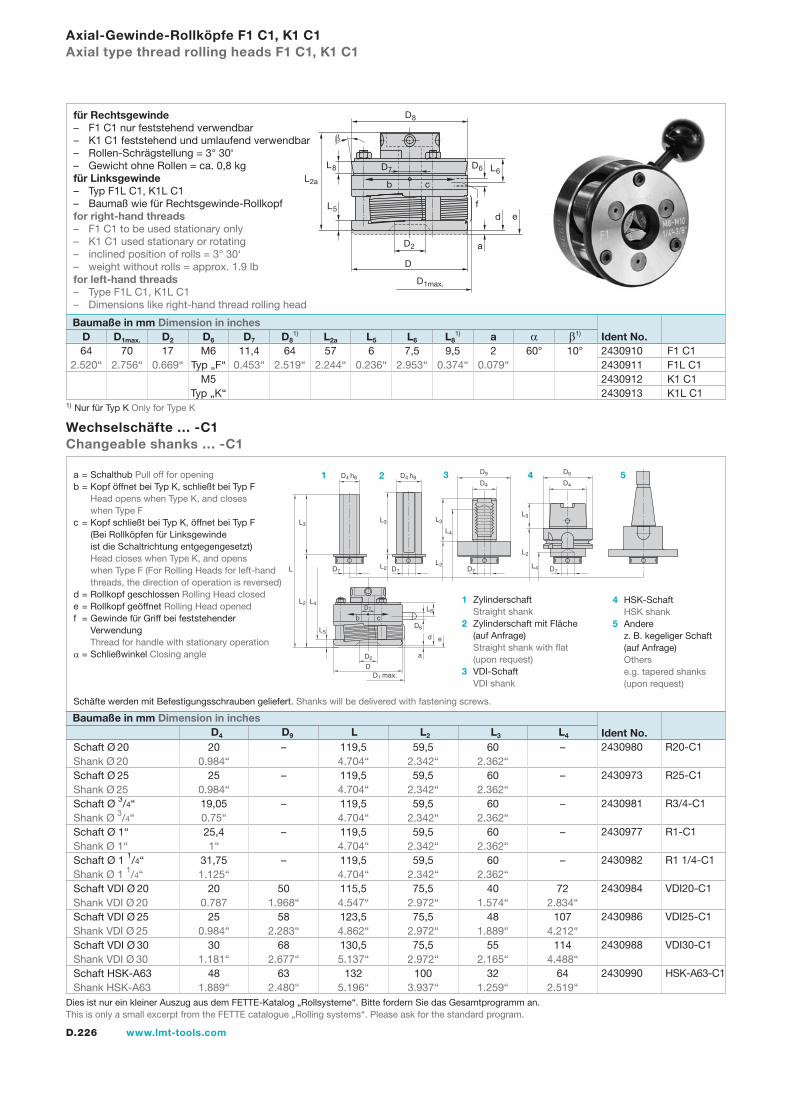
D.226 www.lmt-tools.com
Axial-Gewinde-Rollköpfe F1 C1, K1 C1Axial type thread rolling heads F1 C1, K1 C1
Schaft Ø 20 20 – 119,5 59,5 60 – Shank Ø 20 0.984“ 4.704“ 2.342“ 2.362“ Schaft Ø 25 25 – 119,5 59,5 60 – Shank Ø 25 0.984“ 4.704“ 2.342“ 2.362“ Schaft Ø 3/4“ 19,05 – 119,5 59,5 60 – Shank Ø 3/4“ 0.75“ 4.704“ 2.342“ 2.362“ Schaft Ø 1“ 25,4 – 119,5 59,5 60 – Shank Ø 1“ 1“ 4.704“ 2.342“ 2.362“ Schaft Ø 1 1/4“ 31,75 – 119,5 59,5 60 – Shank Ø 1 1/4“ 1.125“ 4.704“ 2.342“ 2.362“ Schaft VDI Ø 20 20 50 115,5 75,5 40 72 Shank VDI Ø 20 0.787 1.968“ 4.547“ 2.972“ 1.574“ 2.834“ Schaft VDI Ø 25 25 58 123,5 75,5 48 107 Shank VDI Ø 25 0.984“ 2.283“ 4.862“ 2.972“ 1.889“ 4.212“ Schaft VDI Ø 30 30 68 130,5 75,5 55 114 Shank VDI Ø 30 1.181“ 2.677“ 5.137“ 2.972“ 2.165“ 4.488“ Schaft HSK-A63 48 63 132 100 32 64 Shank HSK-A63 1.889“ 2.480“ 5.196“ 3.937“ 1.259“ 2.519“
Wechselschäfte … -C1Changeable shanks … -C1
64 70 17 M6 11,4 64 57 6 7,5 9,5 2 60° 10° 2.520“ 2.756“ 0.669“ Typ „F“ 0.453“ 2.519“ 2.244“ 0.236“ 2.953“ 0.374“ 0.079“ M5 Typ „K“
Baumaße in mm Dimension in inches D D1max. D2 D6 D7 D8
1) L2a L5 L6 L81) a α β1)
b c
a
d
D7
D4 h8
b cL6
D6
e
D2
DD1 max.
L
L2
L5
L3
L4
D7
D4 h8
D7
D4
D9
D7
D4
D9
L2
L3
L2
L3
L4
L2
L3
L4
D7
Ident No. 2430980 R20-C1
2430973 R25-C1
2430981 R3/4-C1
2430977 R1-C1
2430982 R1 1/4-C1
2430984 VDI20-C1
2430986 VDI25-C1
2430988 VDI30-C1
2430990 HSK-A63-C1
Baumaße in mm Dimension in inches D4 D9 L L2 L3 L4
a = Schalthub Pull off for openingb = Kopf öffnet bei Typ K, schließt bei Typ F Head opens when Type K, and closes when Type Fc = Kopf schließt bei Typ K, öffnet bei Typ F (Bei Rollköpfen für Linksgewinde ist die Schaltrichtung entgegengesetzt) Head closes when Type K, and opens when Type F (For Rolling Heads for left-hand threads, the direction of operation is reversed)d = Rollkopf geschlossen Rolling Head closede = Rollkopf geöffnet Rolling Head openedf = Gewinde für Griff bei feststehender Verwendung Thread for handle with stationary operationα = Schließwinkel Closing angle
1 Zylinderschaft Straight shank2 Zylinderschaft mit Fläche (auf Anfrage) Straight shank with flat (upon request)3 VDI-Schaft VDI shank
4 HSK-Schaft HSK shank5 Andere z. B. kegeliger Schaft (auf Anfrage) Others e.g. tapered shanks (upon request)
1 2 3 4 5
2430910 F1 C12430911 F1L C12430912 K1 C12430913 K1L C1
b
D6
L2a
L8
L5
D1max.
D2
D
a
e
L6
D8
c
D7
df
Schäfte werden mit Befestigungsschrauben geliefert. Shanks will be delivered with fastening screws.
Ident No.
1) Nur für Typ K Only for Type K
für Rechtsgewinde– F1 C1 nur feststehend verwendbar– K1 C1 feststehend und umlaufend verwendbar– Rollen-Schrägstellung = 3° 30‘– Gewicht ohne Rollen = ca. 0,8 kgfür Linksgewinde– Typ F1L C1, K1L C1– Baumaß wie für Rechtsgewinde-Rollkopffor right-hand threads– F1 C1 to be used stationary only– K1 C1 used stationary or rotating– inclined position of rolls = 3° 30‘– weight without rolls = approx. 1.9 lbfor left-hand threads– Type F1L C1, K1L C1– Dimensions like right-hand thread rolling head
Dies ist nur ein kleiner Auszug aus dem FETTE-Katalog „Rollsysteme“. Bitte fordern Sie das Gesamtprogramm an.This is only a small excerpt from the FETTE catalogue „Rolling systems“. Please ask for the standard program.
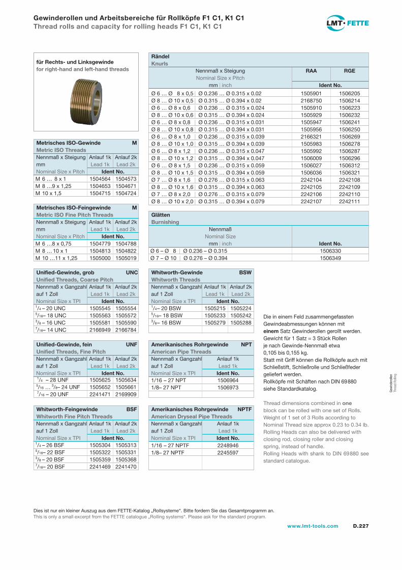
D.227www.lmt-tools.com
Gewinderollen und Arbeitsbereiche für Rollköpfe F1 C1, K1 C1Thread rolls and capacity for rolling heads F1 C1, K1 C1
für Rechts- und Linksgewindefor right-hand and left-hand threads
Die in einem Feld zusammengefassten Gewindeabmessungen können mit einem Satz Gewinderollen gerollt werden.Gewicht für 1 Satz = 3 Stück Rollen je nach Gewinde-Nennmaß etwa 0,105 bis 0,155 kg.Statt mit Griff können die Rollköpfe auch mit Schließstift, Schließrolle und Schließfeder geliefert werden.Rollköpfe mit Schäften nach DIN 69880 siehe Standardkatalog.
Thread dimensions combined in one block can be rolled with one set of Rolls.Weight of 1 set of 3 Rolls according to Nominal Thread size approx 0.23 to 0.34 lb.Rolling Heads can also be delivered with closing rod, closing roller and closing spring, instead of handle.Rolling Heads with shank to DIN 69880 see standard catalogue.
Ø 6 … Ø 8 x 0,5 | Ø 0.236 … Ø 0.315 x 0.02 1505901 1506205Ø 8 … Ø 10 x 0,5 | Ø 0.315 … Ø 0.394 x 0.02 2168750 1506214Ø 6 … Ø 8 x 0,6 | Ø 0.236 … Ø 0.315 x 0.024 1505910 1506223Ø 8 … Ø 10 x 0,6 | Ø 0.315 … Ø 0.394 x 0.024 1505929 1506232Ø 6 … Ø 8 x 0,8 | Ø 0.236 … Ø 0.315 x 0.031 1505947 1506241Ø 8 … Ø 10 x 0,8 | Ø 0.315 … Ø 0.394 x 0.031 1505956 1506250Ø 6 … Ø 8 x 1,0 | Ø 0.236 … Ø 0.315 x 0.039 2166321 1506269Ø 8 … Ø 10 x 1,0 | Ø 0.315 … Ø 0.394 x 0.039 1505983 1506278Ø 6 … Ø 8 x 1,2 | Ø 0.236 … Ø 0.315 x 0.047 1505992 1506287Ø 8 … Ø 10 x 1,2 | Ø 0.315 … Ø 0.394 x 0.047 1506009 1506296Ø 6 … Ø 8 x 1,5 | Ø 0.236 … Ø 0.315 x 0.059 1506027 1506312Ø 8 … Ø 10 x 1,5 | Ø 0.315 … Ø 0.394 x 0.059 1506036 1506321Ø 7 … Ø 8 x 1,6 | Ø 0.276 … Ø 0.315 x 0.063 2242104 2242108Ø 8 … Ø 10 x 1,6 | Ø 0.315 … Ø 0.394 x 0.063 2242105 2242109Ø 7 … Ø 8 x 2,0 | Ø 0.276 … Ø 0.315 x 0.079 2242106 2242110Ø 8 … Ø 10 x 2,0 | Ø 0.315 … Ø 0.394 x 0.079 2242107 2242111
Rändel Knurls
Nennmaß x Steigung RAA RGE Nominal Size x Pitch mm | inch Ident No.
M 6 … 8 x 1 1504564 1504573M 8 … 9 x 1,25 1504653 1504671M 10 x 1,5 1504715 1504724
Metrisches ISO-Gewinde MMetric ISO Threads
Nennmaß x Steigung Anlauf 1k Anlauf 2k mm Lead 1k Lead 2k Nominal Size x Pitch Ident No.
M 6 … 8 x 0,75 1504779 1504788M 8 … 10 x 1 1504813 1504822M 10 … 11 x 1,25 1505000 1505019
Metrisches ISO-Feingewinde MMetric ISO Fine Pitch Threads
Nennmaß x Steigung Anlauf 1k Anlauf 2k mm Lead 1k Lead 2k Nominal Size x Pitch Ident No.
Ø 6 – Ø 8 | Ø 0.236 – Ø 0.315 1506330Ø 7 – Ø 10 | Ø 0.276 – Ø 0.394 1506349
Glätten Burnishing
Nennmaß Nominal Size mm | inch Ident No.
1/4 – 20 UNC 1505545 15055545/16 – 18 UNC 1505563 15055723/8 – 16 UNC 1505581 15055907/16 – 14 UNC 2166949 2166784
Unified-Gewinde, grob UNCUnified Threads, Coarse Pitch
Nennmaß x Gangzahl Anlauf 1k Anlauf 2k auf 1 Zoll Lead 1k Lead 2k Nominal Size x TPI Ident No.
1/4 – 28 UNF 1505625 1505634 5/16 … 3/8 – 24 UNF 1505652 1505661 7/16 – 20 UNF 2241471 2169909
Unified-Gewinde, fein UNFUnified Threads, Fine Pitch
Nennmaß x Gangzahl Anlauf 1k Anlauf 2k auf 1 Zoll Lead 1k Lead 2k Nominal Size x TPI Ident No.
1/4 – 26 BSF 1505304 15053135/16 – 22 BSF 1505322 15053313/8 – 20 BSF 1505359 15053687/16 – 20 BSF 2241469 2241470
Whitworth-Feingewinde BSFWhitworth Fine Pitch Threads
Nennmaß x Gangzahl Anlauf 1k Anlauf 2k auf 1 Zoll Lead 1k Lead 2k Nominal Size x TPI Ident No.
1/4 – 20 BSW 1505215 1505224 5/16 – 18 BSW 1505233 1505242 3/8 – 16 BSW 1505279 1505288
Whitworth-Gewinde BSWWhitworth Threads
Nennmaß x Gangzahl Anlauf 1k Anlauf 2k auf 1 Zoll Lead 1k Lead 2k Nominal Size x TPI Ident No.
1/16 – 27 NPT 1506964 1/8 – 27 NPT 1506973
Amerikanisches Rohrgewinde NPTAmerican Pipe Threads
Nennmaß x Gangzahl Anlauf 1k auf 1 Zoll Lead 1k Nominal Size x TPI Ident No.
1/16 – 27 NPTF 2248946 1/8 – 27 NPTF 2245597
Amerikanisches Rohrgewinde NPTFAmerican Dryseal Pipe Threads
Nennmaß x Gangzahl Anlauf 1k auf 1 Zoll Lead 1k Nominal Size x TPI Ident No.
Dies ist nur ein kleiner Auszug aus dem FETTE-Katalog „Rollsysteme“. Bitte fordern Sie das Gesamtprogramm an.This is only a small excerpt from the FETTE catalogue „Rolling systems“. Please ask for the standard program.
Gew
inde
rolle
n Th
read
Rol
ling

D.228 www.lmt-tools.com
1 1 Kupplung 2430915 2430914 Clutch 2 1 Federgehäuse 2164719 2164722 Spring housing 3 1 Zwischenplatte 2164720 2164723 Center plate 4 1 Frontplatte 2164721 2164724 Front plate 5 3 Exzenterbolzen 2164637 Excentric spindles 6 3 Distanzbolzen 2164638 Spacer studs 7 1 Zahnrad 2164639 2164652 Center gear 8 3 Zahnrad 2164640 Spur gear 9 1 Griff 2148840 Handle 10 1 Spiralfeder 2164653 2164641 Coil spring 11 1 Sicherungsring 2164642 Circlip 12 1 Sicherung 2164643 Circlip 13 3 Hartmetall-Laufbuchse 2164705 Carbide bushing 14 3 Zylinderschraube 2148736 Cap screw 15 3 Sechskantmutter 2148397 Hexagon nut 16 1 Ringscheibe 2164644 Ring washer 17 1 Sechskantmutter 2148397 Hexagon nut 18 3 Gewinderolle siehe Einsatzfall Thread roll individual 19 2 Gewindestift2) 2142064 Set screw 19 1 Gewindestift2) 2142062 Set screw 19 1 Gewindestift2) 2142065 Set screw 23 1 Kugelknopf 2141699 Ball 24 1 Scheibe 2148867 Washer
Ersatzteile für Rollkopf F1 C1, K1 C1Spare parts for rolling head F1 C1, K1 C1
1 1 Kupplung 2430914 2430915 Clutch 2 1 Federgehäuse 2164634 2164649 Spring housing 3 1 Zwischenplatte 2164635 2164650 Centre plate 4 1 Frontplatte 2164636 2164651 Front plate 5 3 Exzenterbolzen 2164637 Excentric spindles 6 3 Distanzbolzen 2164638 Spacer studs 7 1 Zahnrad 2164639 2164652 Center gear 8 3 Zahnrad 2164640 Spur gear 9 1 Griff 2148841 Handle 10 1 Spiralfeder 2164641 2164653 Coil spring 11 1 Sicherungsring 2164642 Circlip 12 1 Sicherung 2164643 Circlip 13 3 Hartmetall-Laufbuchse 2164705 Carbide bushing 14 3 Zylinderschraube 2148736 Cap screw 15 3 Sechskantmutter 2148397 Hexagon nut 16 1 Ringscheibe 2146644 Ring washer 17 1 Sechskantmutter 2148393 Hexagon nut 18 3 Gewinderolle siehe Einsatzfall Thread roll individual 19 2 Gewindestift – Set screw 19 1 Gewindestift – Set screw 19 1 Gewindestift – Set screw 23 1 Kugelknopf 2141700 Ball 24 1 Scheibe 2144250 Washer
Rollkopf F1 C1 F1L C1Rolling head Linksgewinde
Left hand thread Teil Nr. Stück Benennung Part no. Qty. Part description Ident No. Ident No.
Rollkopf K1 C1 K1L C1Rolling head Linksgewinde
Left hand thread Teil Nr. Stück Benennung Part no. Qty. Part description Ident No. Ident No.
Innenanschlag 2430916 2430917 Internal stop complete 20 1 Schraubenstutzen 2164645 2164654 Stop screw body 21 1 Anschlagschraube 2164646 2164655 Stop screw 22 1 Sechskantmutter 2166124 2166125 Hexagon nut
Zubehör Innenanschlag1) IS1 C1 IS1L C1Option internal stop Linksgewinde
Left hand thread Teil Nr. Stück Benennung Part no. Qty. Part description Ident No. Ident No.
Bei Bestellung von Einzelteilen bitte Rollkopf-Typ, Teil Nr. und Ident No. in der Stückliste angeben!When ordering spare parts, please state thread rolling head Type, Part No. and Ident No.!
1) Nur für Maschinen ohne gesteuerten Vorschub. Bitte zusätzlich bestellen.
1) Only required for machines without controlled feed stop. If required, please order additionally!2)
Teil 19 wird in der Explosionszeichnung nicht gezeigt (Zum Festsetzen eines Gewindebolzens)2) Part 19 not shown in the view (Locking screw for adjustment with type K)
Dies ist nur ein kleiner Auszug aus dem FETTE-Katalog „Rollsysteme“. Bitte fordern Sie das Gesamtprogramm an.This is only a small excerpt from the FETTE catalogue „Rolling systems“. Please ask for the standard program.
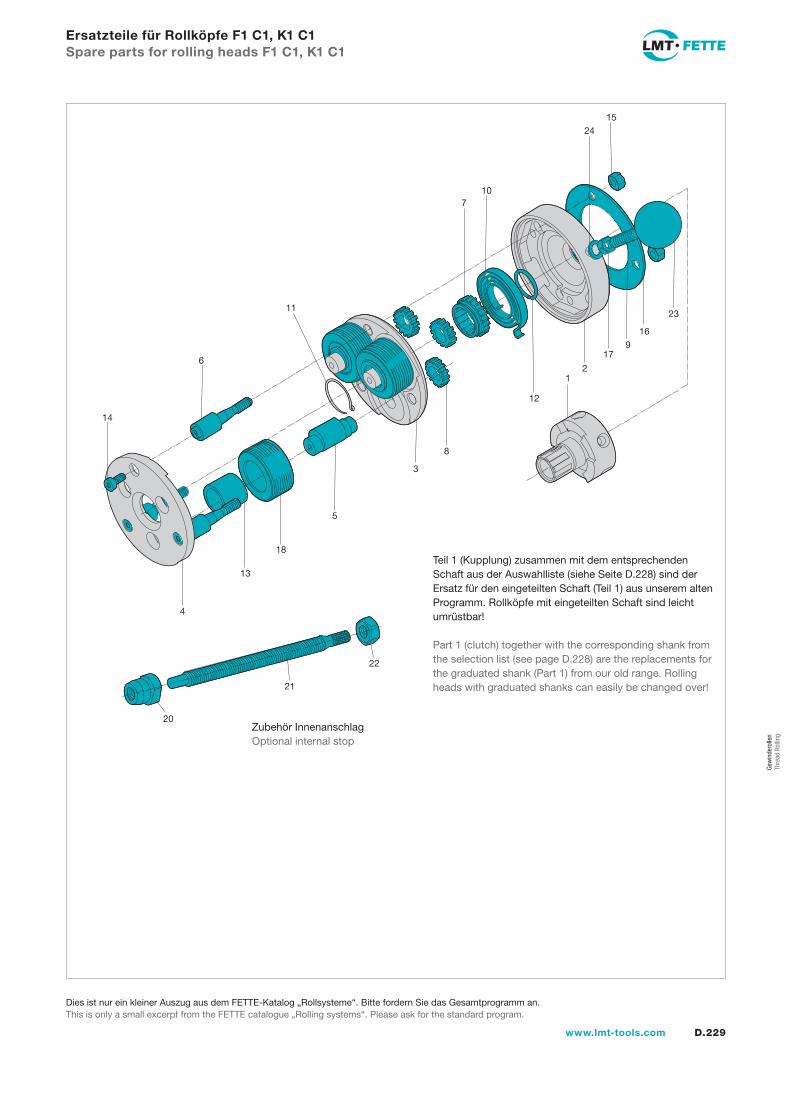
D.229www.lmt-tools.com
Ersatzteile für Rollköpfe F1 C1, K1 C1Spare parts for rolling heads F1 C1, K1 C1
14
6
11
710
2415
23
16
179
21
12
8
3
5
18
13
4
Teil 1 (Kupplung) zusammen mit dem entsprechenden Schaft aus der Auswahlliste (siehe Seite D.228) sind der Ersatz für den eingeteilten Schaft (Teil 1) aus unserem alten Programm. Rollköpfe mit eingeteilten Schaft sind leicht umrüstbar!
Part 1 (clutch) together with the corresponding shank from the selection list (see page D.228) are the replacements for the graduated shank (Part 1) from our old range. Rolling heads with graduated shanks can easily be changed over!
20
21
22
Zubehör InnenanschlagOptional internal stop
Dies ist nur ein kleiner Auszug aus dem FETTE-Katalog „Rollsysteme“. Bitte fordern Sie das Gesamtprogramm an.This is only a small excerpt from the FETTE catalogue „Rolling systems“. Please ask for the standard program.
Gew
inde
rolle
n Th
read
Rol
ling
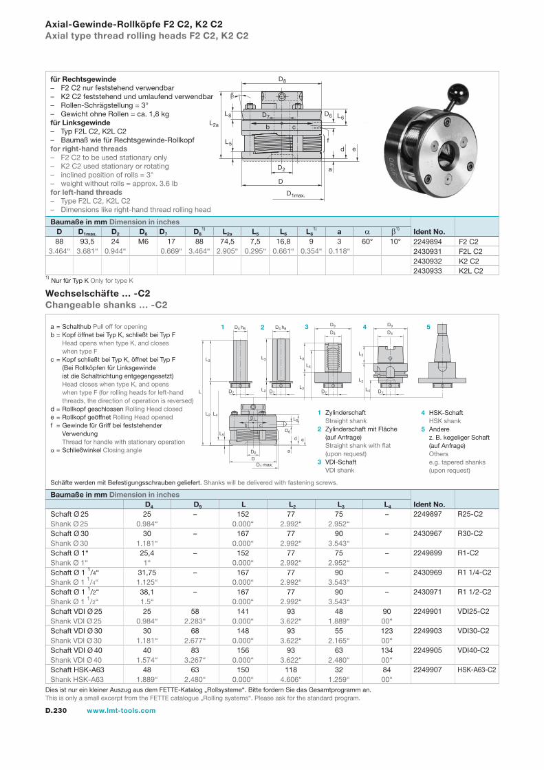
D.230 www.lmt-tools.com
Schaft Ø 25 25 – 152 77 75 – Shank Ø 25 0.984“ 0.000“ 2.992“ 2.952“ Schaft Ø 30 30 – 167 77 90 – Shank Ø 30 1.181“ 0.000“ 2.992“ 3.543“ Schaft Ø 1“ 25,4 – 152 77 75 – Shank Ø 1“ 1“ 0.000“ 2.992“ 2.952“ Schaft Ø 1 1/4“ 31,75 – 167 77 90 – Shank Ø 1 1/4“ 1.125“ 0.000“ 2.992“ 3.543“ Schaft Ø 1 1/2“ 38,1 – 167 77 90 – Shank Ø 1 1/2“ 1.5“ 0.000“ 2.992“ 3.543“ Schaft VDI Ø 25 25 58 141 93 48 90 Shank VDI Ø 25 0.984“ 2.283“ 0.000“ 3.622“ 1.889“ 00“ Schaft VDI Ø 30 30 68 148 93 55 123 Shank VDI Ø 30 1.181“ 2.677“ 0.000“ 3.622“ 2.165“ 00“ Schaft VDI Ø 40 40 83 156 93 63 134 Shank VDI Ø 40 1.574“ 3.267“ 0.000“ 3.622“ 2.480“ 00“ Schaft HSK-A63 48 63 150 118 32 84 Shank HSK-A63 1.889“ 2.480“ 0.000“ 4.606“ 1.259“ 00“
2249897 R25-C2
2430967 R30-C2
2249899 R1-C2
2430969 R1 1/4-C2
2430971 R1 1/2-C2
2249901 VDI25-C2
2249903 VDI30-C2
2249905 VDI40-C2
2249907 HSK-A63-C2
Axial-Gewinde-Rollköpfe F2 C2, K2 C2Axial type thread rolling heads F2 C2, K2 C2
Wechselschäfte … -C2Changeable shanks … -C2
Baumaße in mm Dimension in inches D D1max. D2 D6 D7 D8
1) L2a L5 L6 L81) a α β1)
b c
a
d
D7
D4 h8
b cL6
D6
e
D2
DD1 max.
L
L2
L5
L3
L4
D7
D4 h8
D7
D4
D9
D7
D4
D9
L2
L3
L2
L3
L4
L2
L3
L4
D7
Ident No. Baumaße in mm Dimension in inches D4 D9 L L2 L3 L4
a = Schalthub Pull off for openingb = Kopf öffnet bei Typ K, schließt bei Typ F Head opens when type K, and closes when type Fc = Kopf schließt bei Typ K, öffnet bei Typ F (Bei Rollköpfen für Linksgewinde ist die Schaltrichtung entgegengesetzt) Head closes when type K, and opens when type F (for rolling heads for left-hand threads, the direction of operation is reversed)d = Rollkopf geschlossen Rolling Head closede = Rollkopf geöffnet Rolling Head openedf = Gewinde für Griff bei feststehender Verwendung Thread for handle with stationary operationα = Schließwinkel Closing angle
1 Zylinderschaft Straight shank2 Zylinderschaft mit Fläche (auf Anfrage) Straight shank with flat (upon request)3 VDI-Schaft VDI shank
4 HSK-Schaft HSK shank5 Andere z. B. kegeliger Schaft (auf Anfrage) Others e.g. tapered shanks (upon request)
1 2 3 4 5
2249894 F2 C22430931 F2L C22430932 K2 C22430933 K2L C2
b
D6
L2a
L8
L5
D1max.
D2
D
a
e
L6
D8
c
D7
df
Schäfte werden mit Befestigungsschrauben geliefert. Shanks will be delivered with fastening screws.
Ident No.
1) Nur für Typ K Only for type K
88 93,5 24 M6 17 88 74,5 7,5 16,8 9 3 60° 10° 3.464“ 3.681“ 0.944“ 0.669“ 3.464“ 2.905“ 0.295“ 0.661“ 0.354“ 0.118“
für Rechtsgewinde– F2 C2 nur feststehend verwendbar– K2 C2 feststehend und umlaufend verwendbar– Rollen-Schrägstellung = 3°– Gewicht ohne Rollen = ca. 1,8 kgfür Linksgewinde– Typ F2L C2, K2L C2– Baumaß wie für Rechtsgewinde-Rollkopffor right-hand threads– F2 C2 to be used stationary only– K2 C2 used stationary or rotating– inclined position of rolls = 3°– weight without rolls = approx. 3.6 lbfor left-hand threads– Type F2L C2, K2L C2– Dimensions like right-hand thread rolling head
Dies ist nur ein kleiner Auszug aus dem FETTE-Katalog „Rollsysteme“. Bitte fordern Sie das Gesamtprogramm an.This is only a small excerpt from the FETTE catalogue „Rolling systems“. Please ask for the standard program.
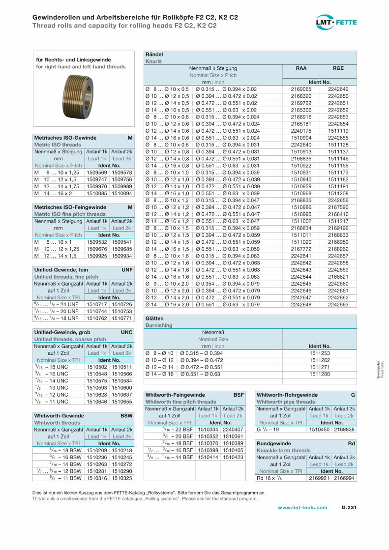
D.231www.lmt-tools.com
Gewinderollen und Arbeitsbereiche für Rollköpfe F2 C2, K2 C2Thread rolls and capacity for rolling heads F2 C2, K2 C2
für Rechts- und Linksgewindefor right-hand and left-hand threads
Ø 8 … Ø 10 x 0,5 | Ø 0.315 … Ø 0.394 x 0.02 2169065 2242649Ø 10 … Ø 12 x 0,5 | Ø 0.394 … Ø 0.472 x 0.02 2168390 2242650Ø 12 … Ø 14 x 0,5 | Ø 0.472 … Ø 0.551 x 0.02 2169722 2242651Ø 14 … Ø 16 x 0,5 | Ø 0.551 … Ø 0.63 x 0.02 2165306 2242652Ø 8 … Ø 10 x 0,6 | Ø 0.315 … Ø 0.394 x 0.024 2168916 2242653Ø 10 … Ø 12 x 0,6 | Ø 0.394 … Ø 0.472 x 0.024 2165181 2242654Ø 12 … Ø 14 x 0,6 | Ø 0.472 … Ø 0.551 x 0.024 2240175 1511119Ø 14 … Ø 16 x 0,6 | Ø 0.551 … Ø 0.63 x 0.024 1510904 2242655Ø 8 … Ø 10 x 0,8 | Ø 0.315 … Ø 0.394 x 0.031 2242640 1511128Ø 10 … Ø 12 x 0,8 | Ø 0.394 … Ø 0.472 x 0.031 1510913 1511137Ø 12 … Ø 14 x 0,8 | Ø 0.472 … Ø 0.551 x 0.031 2168836 1511146Ø 14 … Ø 16 x 0,8 | Ø 0.551 … Ø 0.63 x 0.031 1510922 1511155Ø 8 … Ø 10 x 1,0 | Ø 0.315 … Ø 0.394 x 0.039 1510931 1511173Ø 10 … Ø 12 x 1,0 | Ø 0.394 … Ø 0.472 x 0.039 1510940 1511182Ø 12 … Ø 14 x 1,0 | Ø 0.472 … Ø 0.551 x 0.039 1510959 1511191Ø 14 … Ø 16 x 1,0 | Ø 0.551 … Ø 0.63 x 0.039 1510968 1511208Ø 8 … Ø 10 x 1,2 | Ø 0.315 … Ø 0.394 x 0.047 2168835 2242656Ø 10 … Ø 12 x 1,2 | Ø 0.394 … Ø 0.472 x 0.047 1510986 2167590Ø 12 … Ø 14 x 1,2 | Ø 0.472 … Ø 0.551 x 0.047 1510995 2168410Ø 14 … Ø 16 x 1,2 | Ø 0.551 … Ø 0.63 x 0.047 1511002 1511217Ø 8 … Ø 10 x 1,5 | Ø 0.315 … Ø 0.394 x 0.059 2168834 2169196Ø 10 … Ø 12 x 1,5 | Ø 0.394 … Ø 0.472 x 0.059 1511011 2168833Ø 12 … Ø 14 x 1,5 | Ø 0.472 … Ø 0.551 x 0.059 1511020 2166950Ø 14 … Ø 16 x 1,5 | Ø 0.551 … Ø 0.63 x 0.059 2167772 2168962Ø 8 … Ø 10 x 1,6 | Ø 0.315 … Ø 0.394 x 0.063 2242641 2242657Ø 10 … Ø 12 x 1,6 | Ø 0.394 … Ø 0.472 x 0.063 2242642 2242658Ø 12 … Ø 14 x 1,6 | Ø 0.472 … Ø 0.551 x 0.063 2242643 2242659Ø 14 … Ø 16 x 1,6 | Ø 0.551 … Ø 0.63 x 0.063 2242644 2168821Ø 9 … Ø 10 x 2,0 | Ø 0.354 … Ø 0.394 x 0.079 2242645 2242660Ø 10 … Ø 12 x 2,0 | Ø 0.394 … Ø 0.472 x 0.079 2242646 2242661Ø 12 … Ø 14 x 2,0 | Ø 0.472 … Ø 0.551 x 0.079 2242647 2242662Ø 14 … Ø 16 x 2,0 | Ø 0.551 … Ø 0.63 x 0.079 2242648 2242663
Rändel Knurls
Nennmaß x Steigung RAA RGE Nominal Size x Pitch mm | inch Ident No.
G 1/4 – 19 1510450 2168838
Whitworth-Rohrgewinde G Whitworth pipe threads
Nennmaß x Gangzahl Anlauf 1k Anlauf 2k auf 1 Zoll Lead 1k Lead 2k Nominal Size x TPI Ident No.
Rd 16 x 1/8 2169921 2166994
Rundgewinde Rd Knuckle form threads
Nennmaß x Gangzahl Anlauf 1k Anlauf 2k auf 1 Zoll Lead 1k Lead 2k Nominal Size x TPI Ident No.
Ø 8 – Ø 10 | Ø 0.315 – Ø 0.394 1511253Ø 10 – Ø 12 | Ø 0.394 – Ø 0.472 1511262Ø 12 – Ø 14 | Ø 0.472 – Ø 0.551 1511271Ø 14 – Ø 16 | Ø 0.551 – Ø 0.63 1511280
Glätten Burnishing
Nennmaß Nominal Size mm | inch Ident No.
M 8 … 10 x 1,25 1509569 1509578M 10 … 12 x 1,5 1509747 1509756M 12 … 14 x 1,75 1509970 1509989M 14 … 16 x 2 1510085 1510094
Metrisches ISO-Gewinde M Metric ISO threads
Nennmaß x Steigung Anlauf 1k Anlauf 2k mm Lead 1k Lead 2k Nominal Size x Pitch Ident No.
M 8 … 10 x 1 1509532 1509541M 10 … 12 x 1,25 1509676 1509685M 12 … 14 x 1,5 1509925 1509934
Metrisches ISO-Feingewinde M Metric ISO fine pitch threads
Nennmaß x Steigung Anlauf 1k Anlauf 2k mm Lead 1k Lead 2k Nominal Size x Pitch Ident No.
5/16 … 3/8 – 24 UNF 1510717 15107267/16 … 1/2 – 20 UNF 1510744 15107539/16 … 5/8 – 18 UNF 1510762 1510771
Unified-Gewinde, fein UNF Unified threads, fine pitch
Nennmaß x Gangzahl Anlauf 1k Anlauf 2k auf 1 Zoll Lead 1k Lead 2k Nominal Size x TPI Ident No.
5/16 – 18 UNC 1510502 1510511 3/8 – 16 UNC 1510548 1510566 7/16 – 14 UNC 1510575 1510584 1/2 – 13 UNC 1510593 1510600 9/16 – 12 UNC 1510628 1510637 5/8 – 11 UNC 1510646 1510655
Unified-Gewinde, grob UNC Unified threads, coarse pitch
Nennmaß x Gangzahl Anlauf 1k Anlauf 2k auf 1 Zoll Lead 1k Lead 2k Nominal Size x TPI Ident No.
5/16 – 18 BSW 1510209 1510218 3/8 – 16 BSW 1510236 1510245 7/16 – 14 BSW 1510263 1510272 1/2 … 9/16 – 12 BSW 1510281 1510290 5/8 – 11 BSW 1510316 1510325
Whitworth-Gewinde BSW Whitworth threads
Nennmaß x Gangzahl Anlauf 1k Anlauf 2k auf 1 Zoll Lead 1k Lead 2k Nominal Size x TPI Ident No.
5/16 – 22 BSF 1510334 2240407 3/8 – 20 BSF 1510352 1510361 7/16 – 18 BSF 1510370 1510389 1/2 … 9/16 – 16 BSF 1510398 1510405 5/8 … 11/16 – 14 BSF 1510414 1510423
Whitworth-Feingewinde BSF Whitworth fine pitch threads
Nennmaß x Gangzahl Anlauf 1k Anlauf 2k auf 1 Zoll Lead 1k Lead 2k Nominal Size x TPI Ident No.
Dies ist nur ein kleiner Auszug aus dem FETTE-Katalog „Rollsysteme“. Bitte fordern Sie das Gesamtprogramm an.This is only a small excerpt from the FETTE catalogue „Rolling systems“. Please ask for the standard program.
Gew
inde
rolle
n Th
read
Rol
ling
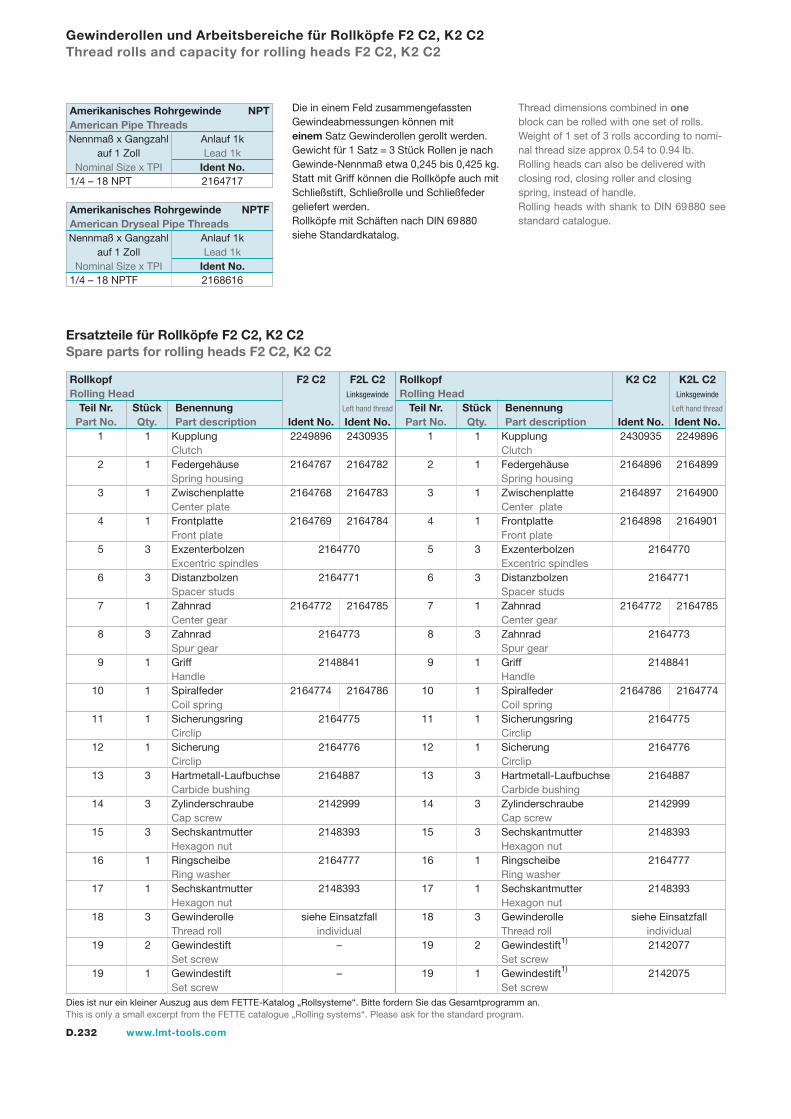
D.232 www.lmt-tools.com
1 1 Kupplung 2430935 2249896 Clutch 2 1 Federgehäuse 2164896 2164899 Spring housing 3 1 Zwischenplatte 2164897 2164900 Center plate 4 1 Frontplatte 2164898 2164901 Front plate 5 3 Exzenterbolzen 2164770 Excentric spindles 6 3 Distanzbolzen 2164771 Spacer studs 7 1 Zahnrad 2164772 2164785 Center gear 8 3 Zahnrad 2164773 Spur gear 9 1 Griff 2148841 Handle 10 1 Spiralfeder 2164786 2164774 Coil spring 11 1 Sicherungsring 2164775 Circlip 12 1 Sicherung 2164776 Circlip 13 3 Hartmetall-Laufbuchse 2164887 Carbide bushing 14 3 Zylinderschraube 2142999 Cap screw 15 3 Sechskantmutter 2148393 Hexagon nut 16 1 Ringscheibe 2164777 Ring washer 17 1 Sechskantmutter 2148393 Hexagon nut 18 3 Gewinderolle siehe Einsatzfall Thread roll individual 19 2 Gewindestift1) 2142077 Set screw 19 1 Gewindestift1) 2142075 Set screw
Ersatzteile für Rollköpfe F2 C2, K2 C2Spare parts for rolling heads F2 C2, K2 C2
Gewinderollen und Arbeitsbereiche für Rollköpfe F2 C2, K2 C2Thread rolls and capacity for rolling heads F2 C2, K2 C2
Die in einem Feld zusammengefassten Gewindeabmessungen können mit einem Satz Gewinderollen gerollt werden.Gewicht für 1 Satz = 3 Stück Rollen je nach Gewinde-Nennmaß etwa 0,245 bis 0,425 kg.Statt mit Griff können die Rollköpfe auch mit Schließstift, Schließrolle und Schließfeder geliefert werden.Rollköpfe mit Schäften nach DIN 69880 siehe Standardkatalog.
Thread dimensions combined in one block can be rolled with one set of rolls.Weight of 1 set of 3 rolls according to nomi-nal thread size approx 0.54 to 0.94 lb.Rolling heads can also be delivered with closing rod, closing roller and closing spring, instead of handle.Rolling heads with shank to DIN 69880 see standard catalogue.
1 1 Kupplung 2249896 2430935 Clutch 2 1 Federgehäuse 2164767 2164782 Spring housing 3 1 Zwischenplatte 2164768 2164783 Center plate 4 1 Frontplatte 2164769 2164784 Front plate 5 3 Exzenterbolzen 2164770 Excentric spindles 6 3 Distanzbolzen 2164771 Spacer studs 7 1 Zahnrad 2164772 2164785 Center gear 8 3 Zahnrad 2164773 Spur gear 9 1 Griff 2148841 Handle 10 1 Spiralfeder 2164774 2164786 Coil spring 11 1 Sicherungsring 2164775 Circlip 12 1 Sicherung 2164776 Circlip 13 3 Hartmetall-Laufbuchse 2164887 Carbide bushing 14 3 Zylinderschraube 2142999 Cap screw 15 3 Sechskantmutter 2148393 Hexagon nut 16 1 Ringscheibe 2164777 Ring washer 17 1 Sechskantmutter 2148393 Hexagon nut 18 3 Gewinderolle siehe Einsatzfall Thread roll individual 19 2 Gewindestift – Set screw 19 1 Gewindestift – Set screw
Rollkopf F2 C2 F2L C2Rolling Head Linksgewinde
Left hand thread Teil Nr. Stück Benennung Part No. Qty. Part description Ident No. Ident No.
Rollkopf K2 C2 K2L C2Rolling Head Linksgewinde
Left hand thread Teil Nr. Stück Benennung Part No. Qty. Part description Ident No. Ident No.
1/4 – 18 NPT 2164717
1/4 – 18 NPTF 2168616
Amerikanisches Rohrgewinde NPTFAmerican Dryseal Pipe Threads
Nennmaß x Gangzahl Anlauf 1k auf 1 Zoll Lead 1k Nominal Size x TPI Ident No.
Amerikanisches Rohrgewinde NPTAmerican Pipe Threads
Nennmaß x Gangzahl Anlauf 1k auf 1 Zoll Lead 1k Nominal Size x TPI Ident No.
Dies ist nur ein kleiner Auszug aus dem FETTE-Katalog „Rollsysteme“. Bitte fordern Sie das Gesamtprogramm an.This is only a small excerpt from the FETTE catalogue „Rolling systems“. Please ask for the standard program.
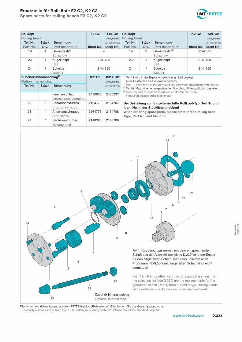
D.233www.lmt-tools.com
19 1 Gewindestift – Set screw 23 1 Kugelknopf 2141700 Ball 24 1 Scheibe 2144250 Washer
19 1 Gewindestift1) 2142075 Set screw 23 1 Kugelknopf 2141700 Ball 24 1 Scheibe 2144250 Washer
Innenanschlag 2430936 2430937 Internal stop complete 20 1 Schraubenstutzen 2164779 2164787 Stop screw body 21 1 Anschlagschraube 2164778 2164788 Stop screw 22 1 Sechskantmutter 2148390 2148700 Hexagon nut
Ersatzteile für Rollköpfe F2 C2, K2 C2Spare parts for rolling heads F2 C2, K2 C2
Rollkopf F2 C2 F2L C2Rolling head Linksgewinde
Left hand thread Teil Nr. Stück Benennung Part No. Qty. Part description Ident No. Ident No.
Rollkopf K2 C2 K2L C2Rolling Head Linksgewinde
Left hand thread Teil Nr. Stück Benennung Part No. Qty. Part description Ident No. Ident No.
Bei Bestellung von Einzelteilen bitte Rollkopf-Typ, Teil Nr. und Ident No. in der Stückliste angeben!When ordering spare parts, please state thread rolling head Type, Part No. and Ident no.!
20
21
22
1) Teil 19 wird in der Explosionszeichnung nicht gezeigt
(Zum Festsetzen eines Gewindebolzens)1) Part 19 not shown in the view (Locking screw for adjustment with type K)2)
Nur für Maschinen ohne gesteuerten Vorschub. Bitte zusätzlich bestellen.2) Only required for machines without controlled feed stop. If required, please order additionally!
Zubehör InnenanschlagOptional internal stop
Zubehör Innenanschlag2) IS2 C2 IS2 L C2Option Internal stop Linksgewinde
Left hand thread Teil Nr. Stück Benennung
14
6
11
710
2415
23
16
179
21
12
8
3
5
18
13
4
Teil 1 (Kupplung) zusammen mit dem entsprechenden Schaft aus der Auswahlliste (siehe D.232) sind der Ersatz für den eingeteilten Schaft (Teil 1) aus unserem alten Programm. Rollköpfe mit eingeteilten Schaft sind leicht umrüstbar!
Part 1 (clutch) together with the corresponding shank from the selection list (see D.232) are the replacements for the graduated shank (Part 1) from our old range. Rolling heads with graduated shanks can easily be changed over!
Dies ist nur ein kleiner Auszug aus dem FETTE-Katalog „Rollsysteme“. Bitte fordern Sie das Gesamtprogramm an.This is only a small excerpt from the FETTE catalogue „Rolling systems“. Please ask for the standard program.
Gew
inde
rolle
n Th
read
Rol
ling
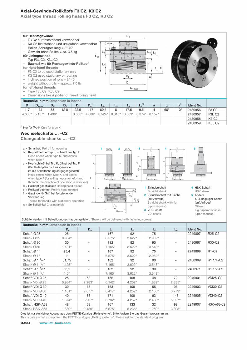
D.234 www.lmt-tools.com
Axial-Gewinde-Rollköpfe F3 C2, K3 C2Axial type thread rolling heads F3 C2, K3 C2
Schaft Ø 25 25 – 167 92 75 – Shank Ø 25 0.984“ 6.575“ 3.622“ 2.952“ Schaft Ø 30 30 – 182 92 90 – Shank Ø 30 1.181“ 7.165“ 3.622“ 3.543“ Schaft Ø 1“ 25,4 – 167 92 75 – Shank Ø 1“ 1“ 6.575“ 3.622“ 2.952“ Schaft Ø 1 1/4“ 31,75 – 182 92 90 – Shank Ø 1 1/4“ 1.125“ 7.165“ 3.622“ 3.543“ Schaft Ø 1 1/2“ 38,1 – 182 92 90 – Shank Ø 1 1/2“ 1.5“ 7.165“ 3.622“ 3.543“ Schaft VDI Ø 25 25 58 156 108 48 72 Shank VDI Ø 25 0.984“ 2.283“ 6.142“ 4.252“ 1.889“ 2.835“ Schaft VDI Ø 30 30 68 163 108 55 96 Shank VDI Ø 30 1.181“ 2.677“ 6.417“ 4.252“ 2.165“ 3.779“ Schaft VDI Ø 40 40 83 171 108 63 148 Shank VDI Ø 40 1.574“ 3.267“ 6.732“ 4.252“ 2.480“ 5.827“ Schaft HSK-A63 48 63 167 133 32 99 Shank HSK-A63 1.889“ 2.480“ 6.575“ 5.236“ 1.259“ 3.898“
2249897 R25-C2
2430967 R30-C2
2249899 R1-C2
2430969 R1 1/4-C2
2430971 R1 1/2-C2
2249901 VDI25-C2
2249903 VDI30-C2
2249905 VDI40-C2
2249907 HSK-A63-C2
Wechselschäfte … -C2Changeable shanks … -C2
Baumaße in mm Dimension in inches D D1max. D2 D6 D7 D8
1) L2a L5 L6 L81) a α β1)
b c
a
d
D7
D4 h8
b cL6
D6
e
D2
DD1 max.
L
L2
L5
L3
L4
D7
D4 h8
D7
D4
D9
D7
D4
D9
L2
L3
L2
L3
L4
L2
L3
L4
D7
Ident No. Baumaße in mm Dimension in inches
D4 D9 L L2 L3 L4
a = Schalthub Pull off for openingb = Kopf öffnet bei Typ K, schließt bei Typ F Head opens when type K, and closes when type Fc = Kopf schließt bei Typ K, öffnet bei Typ F (Bei Rollköpfen für Linksgewinde ist die Schaltrichtung entgegengesetzt) Head closes when type K, and opens when type F (for rolling heads for left-hand threads, the direction of operation is reversed)d = Rollkopf geschlossen Rolling head closede = Rollkopf geöffnet Rolling head openedf = Gewinde für Griff bei feststehender Verwendung Thread for handle with stationary operationα = Schließwinkel Closing angle
1 Zylinderschaft Straight shank2 Zylinderschaft mit Fläche (auf Anfrage) Straight shank with flat (upon request)3 VDI-Schaft VDI shank
4 HSK-Schaft HSK shank5 Andere z. B. kegeliger Schaft (auf Anfrage) Others e.g. tapered shanks (upon request)
1 2 3 4 5
2430956 F3 C22430957 F3L C22430958 K3 C22430959 K3L C2
b
D6
L2a
L8
L5
D1max.
D2
D
a
e
L6
D8
c
D7
df
Schäfte werden mit Befestigungsschrauben geliefert. Shanks will be delivered with fastening screws.
Ident No.
1) Nur für Typ K Only for type K
117 131 38 M 8 22,5 117 89,5 8 17,5 9,5 4 60° 10° 4.606“ 5.157“ 1.496“ 0.858“ 4.606“ 3.524“ 0.315“ 0.689“ 0.374“ 0.157“
für Rechtsgewinde– F3 C2 nur feststehend verwendbar– K3 C2 feststehend und umlaufend verwendbar– Rollen-Schrägstellung = 2° 40‘– Gewicht ohne Rollen = ca. 3,5 kgfür Linksgewinde– Typ F3L C2, K3L C2– Baumaß wie für Rechtsgewinde-Rollkopffor right-hand threads– F3 C2 to be used stationary only– K3 C2 used stationary or rotating– inclined position of rolls = 2° 40‘– weight without rolls = approx. 7.0 lbfor left-hand threads– Type F3L C2, K3L C2– Dimensions like right-hand thread rolling head
Dies ist nur ein kleiner Auszug aus dem FETTE-Katalog „Rollsysteme“. Bitte fordern Sie das Gesamtprogramm an.This is only a small excerpt from the FETTE catalogue „Rolling systems“. Please ask for the standard program.
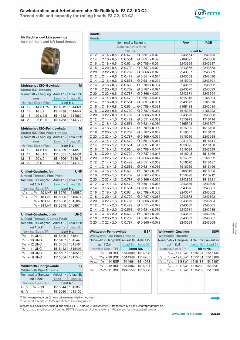
D.235www.lmt-tools.com
Ø 12 … Ø 14 x 0,5 | Ø 0.472 … Ø 0.551 x 0.02 2243564 2243585Ø 14 … Ø 16 x 0,5 | Ø 0.551 … Ø 0.63 x 0.02 2169627 2243586Ø 16 … Ø 18 x 0,5 | Ø 0.63 … Ø 0.709 x 0.02 2243565 2243587Ø 18 … Ø 20 x 0,5 | Ø 0.709 … Ø 0.787 x 0.02 2243566 2243588Ø 20 … Ø 22 x 0,5 | Ø 0.787 … Ø 0.866 x 0.02 2243567 2243589Ø 12 … Ø 14 x 0,6 | Ø 0.472 … Ø 0.551 x 0.024 2243568 2243590Ø 14 … Ø 16 x 0,6 | Ø 0.551 … Ø 0.63 x 0.024 1515909 2243591Ø 16 … Ø 18 x 0,6 | Ø 0.63 … Ø 0.709 x 0.024 2243569 2243592Ø 18 … Ø 20 x 0,6 | Ø 0.709 … Ø 0.787 x 0.024 2243570 2243593Ø 20 … Ø 22 x 0,6 | Ø 0.787 … Ø 0.866 x 0.024 2243571 2243594Ø 12 … Ø 14 x 0,8 | Ø 0.472 … Ø 0.551 x 0.031 1515918 2168024Ø 14 … Ø 16 x 0,8 | Ø 0.551 … Ø 0.63 x 0.031 2243572 2165370Ø 16 … Ø 18 x 0,8 | Ø 0.63 … Ø 0.709 x 0.031 2168428 2243595Ø 18 … Ø 20 x 0,8 | Ø 0.709 … Ø 0.787 x 0.031 1515936 2168023Ø 20 … Ø 22 x 0,8 | Ø 0.787 … Ø 0.866 x 0.031 2243573 2243596Ø 12 … Ø 14 x 1,0 | Ø 0.472 … Ø 0.551 x 0.039 1515972 1516114Ø 14 … Ø 16 x 1,0 | Ø 0.551 … Ø 0.63 x 0.039 2165323 2243597Ø 16 … Ø 18 x 1,0 | Ø 0.63 … Ø 0.709 x 0.039 1515990 1516123Ø 18 … Ø 20 x 1,0 | Ø 0.709 … Ø 0.787 x 0.039 1516007 1516132Ø 20 … Ø 22 x 1,0 | Ø 0.787 … Ø 0.866 x 0.039 1516016 2243598Ø 12 … Ø 14 x 1,2 | Ø 0.472 … Ø 0.551 x 0.047 2241199 1516141Ø 14 … Ø 16 x 1,2 | Ø 0.551 … Ø 0.63 x 0.047 1516025 1516150Ø 16 … Ø 18 x 1,2 | Ø 0.63 … Ø 0.709 x 0.047 1516034 2243599Ø 18 … Ø 20 x 1,2 | Ø 0.709 … Ø 0.787 x 0.047 1516043 1516169Ø 20 … Ø 22 x 1,2 | Ø 0.787 … Ø 0.866 x 0.047 1516052 2168022Ø 12 … Ø 14 x 1,5 | Ø 0.472 … Ø 0.551 x 0.059 1516070 1516187Ø 14 … Ø 16 x 1,5 | Ø 0.551 … Ø 0.63 x 0.059 1516089 1516196Ø 16 … Ø 18 x 1,5 | Ø 0.63 … Ø 0.709 x 0.059 2168315 1516203Ø 18 … Ø 20 x 1,5 | Ø 0.709 … Ø 0.787 x 0.059 1516098 1516212Ø 20 … Ø 22 x 1,5 | Ø 0.787 … Ø 0.866 x 0.059 2242855 1516221Ø 12 … Ø 14 x 1,6 | Ø 0.472 … Ø 0.551 x 0.063 2243575 2243600Ø 14 … Ø 16 x 1,6 | Ø 0.551 … Ø 0.63 x 0.063 2243576 2243601Ø 16 … Ø 18 x 1,6 | Ø 0.63 … Ø 0.709 x 0.063 2243577 2243602Ø 18 … Ø 20 x 1,6 | Ø 0.709 … Ø 0.787 x 0.063 2243578 2243603Ø 20 … Ø 22 x 1,6 | Ø 0.787 … Ø 0.866 x 0.063 2243579 2243604Ø 12 … Ø 14 x 2,0 | Ø 0.472 … Ø 0.551 x 0.079 2243580 2243605Ø 14 … Ø 16 x 2,0 | Ø 0.551 … Ø 0.63 x 0.079 2243581 2242539Ø 16 … Ø 18 x 2,0 | Ø 0.63 … Ø 0.709 x 0.079 2243582 2243606Ø 18 … Ø 20 x 2,0 | Ø 0.709 … Ø 0.787 x 0.079 2243583 2243607Ø 20 … Ø 22 x 2,0 | Ø 0.787 … Ø 0.866 x 0.079 2243584 2243608
Gewinderollen und Arbeitsbereiche für Rollköpfe F3 C2, K3 C2Thread rolls and capacity for rolling heads F3 C2, K3 C2
für Rechts- und Linksgewindefor right-hand and left-hand threads
Rändel Knurls
Nennmaß x Steigung RAA RGE Nominal Size x Pitch mm | inch Ident No.
1) Für Kurzgewinde bis 24 mm Länge einschließlich Auslauf.1) For short threads up to 24 mm/0.945" including runout.
G 1/4 … 3/8 – 19 1515044 1515053G 1/2 – 14 1515080 1515106
Whitworth-Rohrgewinde GWhitworth Pipe Threads
Nennmaß x Gangzahl Anlauf 1k Anlauf 2k auf 1 Zoll Lead 1k Lead 2k Nominal Size x TPI Ident No.
7/16 – 18 BSF 1514900 15149281/2 … 9/16 – 16 BSF 1514946 15149555/8 … 11/16 – 14 BSF 1514964 1514973 3/4 – 12 BSF 1514982 15149917/8 … 15/161) – 11 BSF 2243559 1515008
7/16 – 14 BSW 1515124 15151421/2 … 9/16 – 12 BSW 1515151 15151605/8 … 11/16 – 11 BSW 1515188 1515197 3/4 – 10 BSW 1515222 15152317/8 … 15/16 – 9 BSW 1515259 1515268
Whitworth-Gewinde BSWWhitworth Threads
Nennmaß x Gangzahl Anlauf 1k Anlauf 2k auf 1 Zoll Lead 1k Lead 2k Nominal Size x TPI Ident No.
Whitworth-Feingewinde BSFWhitworth Fine Pitch Threads
Nennmaß x Gangzahl Anlauf 1k Anlauf 2k auf 1 Zoll Lead 1k Lead 2k Nominal Size x TPI Ident No.
M 12 … 14 x 1,75 1514312 1514321M 14 … 16 x 2 1514438 1514447M 18 … 20 x 2,5 1514642 1514660M 20 … 22 x 2,5 1514768 1514777
M 12 … 14 x 1,5 1514269 1514278M 14 … 16 x 1,5 1514385 1514401M 18 … 20 x 2 1514606 1514615M 20 … 22 x 2 2168931 1514740
7/16 … 1/2 – 20 UNF 1515570 1515589 9/16 … 5/8 – 18 UNF 1515605 1515614 3/4 – 16 UNF 1515650 1515669 7/8 – 14 UNF 1515678 2169974
7/16 – 14 UNC 1515400 1515419 1/2 – 13 UNC 1515437 1515446 9/16 – 12 UNC 1515455 1515464 5/8 – 11 UNC 1515482 1515491 3/4 – 10 UNC 1515507 1515516 7/8 – 9 UNC 1515534 1515543
Unified-Gewinde, grob UNCUnified Threads, Coarse Pitch
Nennmaß x Gangzahl Anlauf 1k Anlauf 2k auf 1 Zoll Lead 1k Lead 2k Nominal Size x TPI Ident No.
Unified-Gewinde, fein UNFUnified Threads, Fine Pitch
Nennmaß x Gangzahl Anlauf 1k Anlauf 2k auf 1 Zoll Lead 1k Lead 2k Nominal Size x TPI Ident No.
Metrisches ISO-Feingewinde MMetric ISO Fine Pitch Threads
Nennmaß x Steigung Anlauf 1k Anlauf 2k mm Lead 1k Lead 2k Nominal Size x Pitch Ident No.
Metrisches ISO-Gewinde MMetric ISO Threads
Nennmaß x Steigung Anlauf 1k Anlauf 2k mm Lead 1k Lead 2k Nominal Size x Pitch Ident No.
Dies ist nur ein kleiner Auszug aus dem FETTE-Katalog „Rollsysteme“. Bitte fordern Sie das Gesamtprogramm an.This is only a small excerpt from the FETTE catalogue „Rolling systems“. Please ask for the standard program.
Gew
inde
rolle
n Th
read
Rol
ling
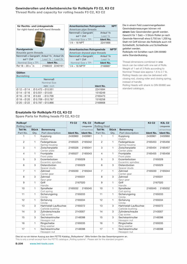
D.236 www.lmt-tools.com
1 1 Kupplung 2430961 2430960 Clutch 2 1 Federgehäuse 2165453 2165456 Spring housing 3 1 Zwischenplatte 2165454 2165457 Center plate 4 1 Frontplatte 2165455 2165458 Front plate 5 3 Exzenterbolzen 2165028 Excentric spindles 6 3 Distanzbolzen 2165029 Spacer studs 7 1 Zahnrad 2165030 2165044 Center gear 8 3 Zahnrad 2165031 Spur gear 9 1 Griff 2167020 Handle 10 1 Spiralfeder 2165045 2165032 Coil spring 11 1 Sicherungsring 2165033 Circlip 12 1 Sicherung 2165034 Circlip 13 3 Hartmetall-Laufbuchse 2165072 Carbide bushing 14 3 Zylinderschraube 2143007 Cap screw 15 3 Sechskantmutter 2148398 Hexagon nut 16 1 Ringscheibe 2165035 Ring washer 17 1 Sechskantmutter 2148398 Hexagon nut
Ersatzteile für Rollköpfe F3 C2, K3 C2Spare Parts for Rolling heads F3 C2, K3 C2
Gewinderollen und Arbeitsbereiche für Rollköpfe F3 C2, K3 C2Thread Rolls and capacity for rolling heads F3 C2, K3 C2
Die in einem Feld zusammengefassten Gewindeabmessungen können mit einem Satz Gewinderollen gerollt werden.Gewicht für 1 Satz = 3 Stück Rollen je nach Gewinde-Nennmaß etwa 0,750 bis 1,200 kg.Statt mit Griff können die Rollköpfe auch mit Schließstift, Schließrolle und Schließfeder geliefert werden.Rollköpfe mit Schäften nach DIN 69880 siehe Standardkatalog.
Thread dimensions combined in one block can be rolled with one set of Rolls.Weight of 1 set of 3 Rolls according to Nominal Thread size approx 1.6 to 2.7 lb.Rolling Heads can also be delivered with closing rod, closing roller and closing spring, instead of handle.Rolling Heads with shank to DIN 69880 see standard catalogue.
1 1 Kupplung 2430960 2430961 Clutch 2 1 Federgehäuse 2165025 2165042 Spring housing 3 1 Zwischenplatte 2165026 2165041 Center plate 4 1 Frontplatte 2165027 2165043 Front plate 5 3 Exzenterbolzen 2165028 Excentric spindles 6 3 Distanzbolzen 2165029 Spacer studs 7 1 Zahnrad 2165030 2165044 Center gear 8 3 Zahnrad 2165031 Spur gear 9 1 Griff 2167020 Handle 10 1 Spiralfeder 2165032 2165045 Coil spring 11 1 Sicherungsring 2165033 Circlip 12 1 Sicherung 2165034 Circlip 13 3 Hartmetall-Laufbuchse 2165072 Carbide bushing 14 3 Zylinderschraube 2143007 Cap screw 15 3 Sechskantmutter 2148398 Hexagon nut 16 1 Ringscheibe 2165035 Ring washer 17 1 Sechskantmutter 2148398 Hexagon nut
Rollkopf F3 C2 F3L C2Rolling head Linksgewinde
Left hand thread Teil Nr. Stück Benennung Part No. Qty. Part description Ident No. Ident No.
Rollkopf K3 C2 K3L C2Rolling Head Linksgewinde
Left hand thread Teil Nr. Stück Benennung Part No. Qty. Part description Ident No. Ident No.
Dies ist nur ein kleiner Auszug aus dem FETTE-Katalog „Rollsysteme“. Bitte fordern Sie das Gesamtprogramm an.This is only a small excerpt from the FETTE catalogue „Rolling systems“. Please ask for the standard program.
Ø 12 – Ø 14 | Ø 0.472 – Ø 0.551 2241694Ø 14 – Ø 16 | Ø 0.551 – Ø 0.63 1516249Ø 16 – Ø 18 | Ø 0.63 – Ø 0.709 2165473Ø 18 – Ø 20 | Ø 0.709 – Ø 0.787 1516258Ø 20 – Ø 22 | Ø 0.787 – Ø 0.866 2169908
Glätten Burnishing
Nennmaß Nominal Size mm | inch Ident No.
1/4 – 18 NPT 2241666
1/4 – 18 NPTF 2166887
Amerikanisches Rohrgewinde NPTFAmerican dryseal pipe threads
Nennmaß x Gangzahl Anlauf 1k auf 1 Zoll Lead 1k Nominal Size x TPI Ident No.
Amerikanisches Rohrgewinde NPTAmerican pipe threads
Nennmaß x Gangzahl Anlauf 1k auf 1 Zoll Lead 1k Nominal Size x TPI Ident No.
Rd 18 – 20 x 1/8 2168222 2240161
Rundgewinde RdKnuckle gorm threads
Nennmaß x Gangzahl Anlauf 1k Anlauf 2k auf 1 Zoll Lead 1k Lead 2k Nominal Size x TPI Ident No.
für Rechts- und Linksgewindefor right-hand and left-hand threads
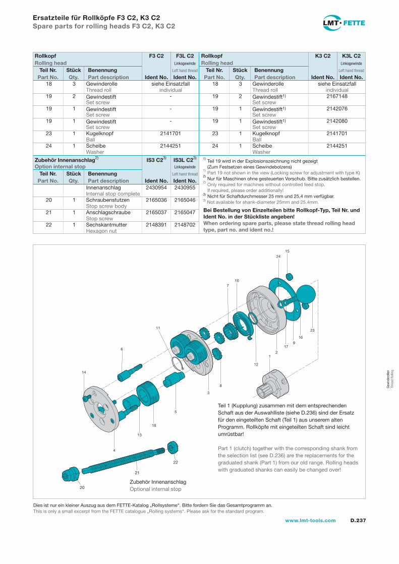
D.237www.lmt-tools.com
Innenanschlag 2430954 2430955 Internal stop complete 20 1 Schraubenstutzen 2165036 2165046 Stop screw body 21 1 Anschlagschraube 2165037 2165047 Stop screw 22 1 Sechskantmutter 2148391 2148702 Hexagon nut
Ersatzteile für Rollköpfe F3 C2, K3 C2Spare parts for rolling heads F3 C2, K3 C2
14
6
11
710
2415
23
16
179
21
12
8
3
5
18
13
4
Teil 1 (Kupplung) zusammen mit dem entsprechenden Schaft aus der Auswahlliste (siehe D.236) sind der Ersatz für den eingeteilten Schaft (Teil 1) aus unserem alten Programm. Rollköpfe mit eingeteilten Schaft sind leicht umrüstbar!
Part 1 (clutch) together with the corresponding shank from the selection list (see D.236) are the replacements for the graduated shank (Part 1) from our old range. Rolling heads with graduated shanks can easily be changed over!
Bei Bestellung von Einzelteilen bitte Rollkopf-Typ, Teil Nr. und Ident No. in der Stückliste angeben!When ordering spare parts, please state thread rolling head type, part no. and ident no.!
18 3 Gewinderolle siehe Einsatzfall Thread roll individual 19 2 Gewindestift - Set screw 19 1 Gewindestift - Set screw 19 1 Gewindestift - Set screw 23 1 Kugelknopf 2141701 Ball 24 1 Scheibe 2144251 Washer
18 3 Gewinderolle siehe Einsatzfall Thread roll individual 19 2 Gewindestift1) 2167148 Set screw 19 1 Gewindestift1) 2142076 Set screw 19 1 Gewindestift1) 2142080 Set screw 23 1 Kugelknopf 2141701 Ball 24 1 Scheibe 2144251 Washer
Rollkopf F3 C2 F3L C2Rolling head Linksgewinde
Left hand thread Teil Nr. Stück Benennung Part No. Qty. Part description Ident No. Ident No.
Rollkopf K3 C2 K3L C2Rolling head Linksgewinde
Left hand thread Teil Nr. Stück Benennung Part No. Qty. Part description Ident No. Ident No.
1) Teil 19 wird in der Explosionszeichnung nicht gezeigt
(Zum Festsetzen eines Gewindebolzens)1)
Part 19 not shown in the view (Locking screw for adjustment with type K)2)
Nur für Maschinen ohne gesteuerten Vorschub. Bitte zusätzlich bestellen.2)
Only required for machines without controlled feed stop. If required, please order additionally!3) Nicht für Schaftdurchmesser 25 mm und 25,4 mm verfügbar.3) Not available for shank-diameter 25mm and 25.4mm.
20
21
22
Zubehör InnenanschlagOptional internal stop
Zubehör Innenanschlag2) IS3 C23) IS3L C23)
Option internal stop Linksgewinde
Left hand thread Teil Nr. Stück Benennung Part No. Qty. Part description Ident No. Ident No.
Dies ist nur ein kleiner Auszug aus dem FETTE-Katalog „Rollsysteme“. Bitte fordern Sie das Gesamtprogramm an.This is only a small excerpt from the FETTE catalogue „Rolling systems“. Please ask for the standard program.
Gew
inde
rolle
n Th
read
Rol
ling
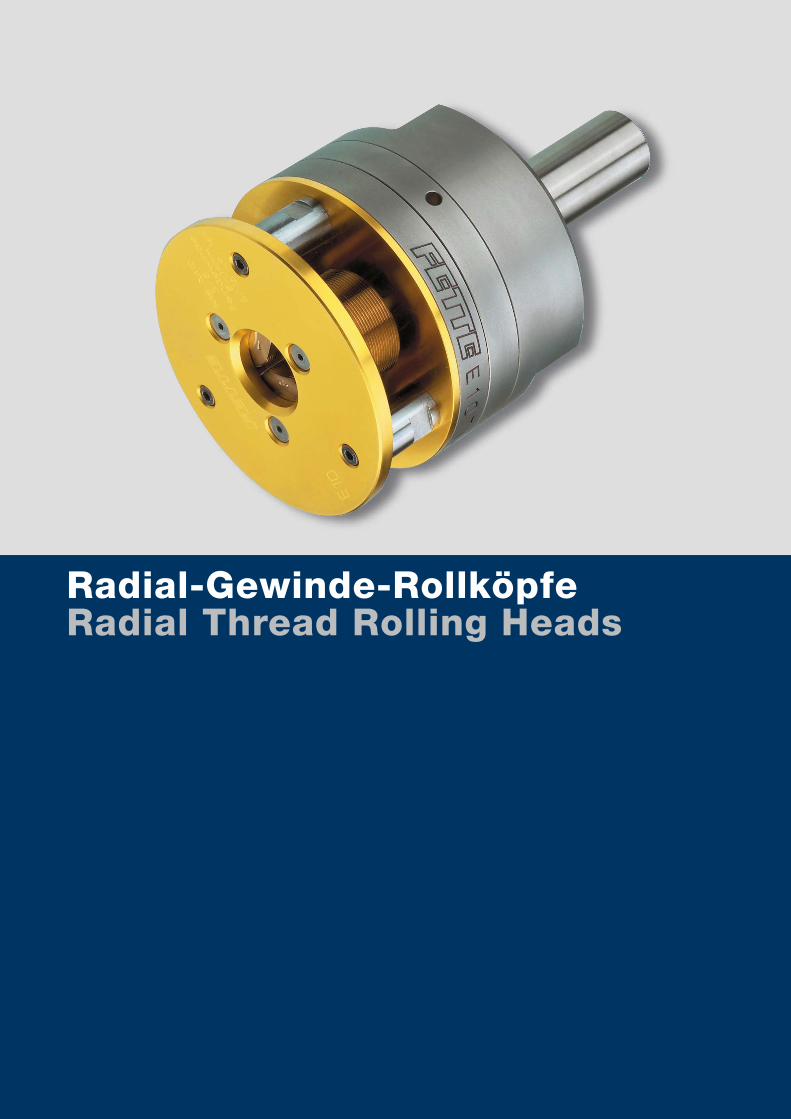
www.lmt-tools.comA.D.238
Radial-Gewinde-RollköpfeRadial Thread Rolling Heads
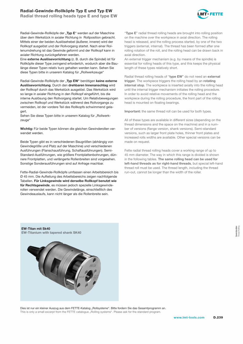
D.239www.lmt-tools.com
Radial-Gewinde-Rollköpfe Typ E und Typ EWRadial thread rolling heads type E and type EW
Radial-Gewinde-Rollköpfe der „Typ E“ werden auf der Maschine über dem Werkstück in axialer Richtung in Rollposition gebracht. Mittels einer der beiden Auslösehebel (äußerer, innerer) wird der Rollkopf ausgelöst und der Rollvorgang startet. Nach einer Rol-lenumdrehung ist das Gewinde geformt und der Rollkopf kann in axialer Richtung zurückgefahren werden.Eine externe Auslösevorrichtung (z. B. durch die Spindel) ist für Rollköpfe dieser Type zwingend erforderlch, wodurch aber die Bau-länge dieser Typen relativ kurz gehalten werden kann. Sehen Sie diese Typen bitte in unserem Katalog für „Rollwerkzeuge“
Radial-Gewinde-Rollköpfe der „Typ EW“ benötigen keine externe Auslösevorrichtung. Durch den drehbaren Innenanschlag wird der Rollkopf durch das Werkstück ausgelöst. Das Werkstück wird so lange in axialer Richtung in den Rollkopf eingeführt, bis die interne Auslösung den Rollvorgang startet. Um Relativbewegungen zwischen Rollkopf und Werkstück während des Rollvorgangs zu vermeiden, ist der vordere Teil des Rollkopfs schwimmend gela-gert.Sehen Sie diese Typen bitte in unserem Katalog für „Rollwerk-zeuge“
Wichtig: Für beide Typen können die gleichen Gewinderollen ver-wendet werden.
Beide Typen gibt es in verschiedenen Baugrößen (abhängig von Gewindegröße und Platz auf der Maschine) und verschiedenen Ausführungen (Flanschausführung, Schaftausführungen). Semi-Standard-Ausführungen, wie größere Frontplattenbohrungen, dün-nere Frontplatten, und verlängerte Rollenbreiten sind vorgesehen. Sonstige Sonderausführungen sind auf Anfrage machbar.
Fette-Radial-Gewinde-Rollköpfe umfassen einen Arbeitsbereich bis Ø 45 mm. Die Aufteilung des Arbeitsbereichs zeigen nachfolgende Tabellen. Für Linksgewinde wird derselbe Rollkopf benutzt wie für Rechtsgewinde, es müssen jedoch spezielle Linksgewinde-rollen verwendet werden. Die Gewindelänge, einschließlich des Gewindeauslaufs, kann nicht länger als die Rollenbreite sein.
“Type E” radial thread rolling heads are brought into rolling position on the machine over the workpiece in axial direction. The rolling head is released, and the rolling process started, by one of the two triggers (external, internal). The thread has been formed after one rolling rotation of the roll, and the rolling head can be drawn back in axial direction.An external trigger mechanism (e.g. by means of the spindle) is essential for rolling heads of this type, and this keeps the physical length of these types relatively short.
Radial thread rolling heads of “type EW” do not need an external trigger. The workpiece triggers the rolling head by an rotating internal stop. The workpiece is inserted axially into the rolling head until the internal trigger mechanism initiates the rolling procedure. In order to avoid relative movements of the rolling head and the workpiece during the rolling procedure, the front part of the rolling head is mounted on floating bearings.
Important: the same thread roll can be used for both types.
All of these types are available in different sizes (depending on the thread dimensions and the space on the machine) and in a num-ber of versions (flange version, shank versions). Semi-standard versions, such as larger front plate holes, thinner front plates and increased rolls widths are available. Other special versions can be made on request.
Fette radial thread rolling heads cover a working range of up to 45 mm diameter. The way in which this range is divided is shown in the following tables. The same rolling head can be used for left-hand threads as for right-hand threads, but special left-hand thread roll must be used. The thread length, including the thread run-out, cannot be longer than the width of the roller.
EW-Titan mit Sk40EW-Titanium with tapered shank SK40
Dies ist nur ein kleiner Auszug aus dem FETTE-Katalog „Rollsysteme“. Bitte fordern Sie das Gesamtprogramm an.This is only a small excerpt from the FETTE catalogue „Rolling systems“. Please ask for the standard program.
Gew
inde
rolle
n Th
read
Rol
ling
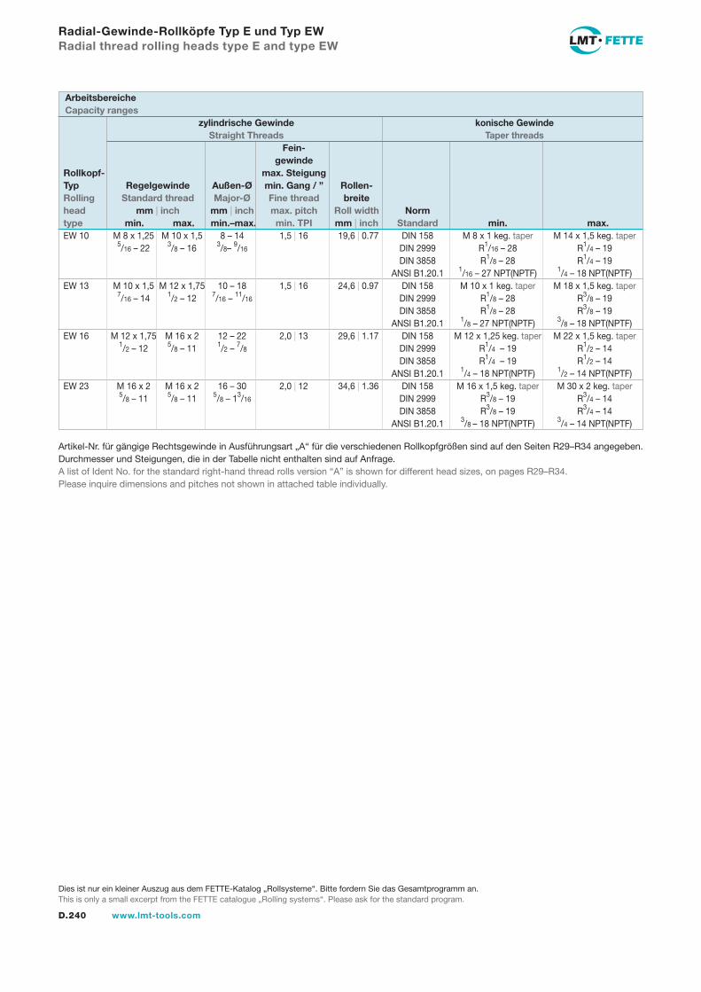
D.240 www.lmt-tools.com
Radial-Gewinde-Rollköpfe Typ E und Typ EWRadial thread rolling heads type E and type EW
EW 10 M 8 x 1,25 M 10 x 1,5 8 – 14 1,5 | 16 19,6 | 0.77 DIN 158 M 8 x 1 keg. taper M 14 x 1,5 keg. taper 5/16 – 22 3/8 – 16 3/8– 9/16 DIN 2999 R1/16 – 28 R1/4 – 19 DIN 3858 R1/8 – 28 R1/4 – 19 ANSI B1.20.1 1/16 – 27 NPT(NPTF) 1/4 – 18 NPT(NPTF)EW 13 M 10 x 1,5 M 12 x 1,75 10 – 18 1,5 | 16 24,6 | 0.97 DIN 158 M 10 x 1 keg. taper M 18 x 1,5 keg. taper 7/16 – 14 1/2 – 12 7/16 – 11/16 DIN 2999 R1/8 – 28 R3/8 – 19 DIN 3858 R1/8 – 28 R3/8 – 19 ANSI B1.20.1 1/8 – 27 NPT(NPTF) 3/8 – 18 NPT(NPTF)EW 16 M 12 x 1,75 M 16 x 2 12 – 22 2,0 | 13 29,6 | 1.17 DIN 158 M 12 x 1,25 keg. taper M 22 x 1,5 keg. taper 1/2 – 12 5/8 – 11 1/2 – 7/8 DIN 2999 R1/4 – 19 R1/2 – 14 DIN 3858 R1/4 – 19 R1/2 – 14 ANSI B1.20.1 1/4 – 18 NPT(NPTF) 1/2 – 14 NPT(NPTF)EW 23 M 16 x 2 M 16 x 2 16 – 30 2,0 | 12 34,6 | 1.36 DIN 158 M 16 x 1,5 keg. taper M 30 x 2 keg. taper 5/8 – 11 5/8 – 11 5/8 – 13/16 DIN 2999 R3/8 – 19 R3/4 – 14 DIN 3858 R3/8 – 19 R3/4 – 14 ANSI B1.20.1 3/8 – 18 NPT(NPTF) 3/4 – 14 NPT(NPTF)
Artikel-Nr. für gängige Rechtsgewinde in Ausführungsart „A“ für die verschiedenen Rollkopfgrößen sind auf den Seiten R29–R34 angegeben.Durchmesser und Steigungen, die in der Tabelle nicht enthalten sind auf Anfrage.A list of Ident No. for the standard right-hand thread rolls version “A” is shown for different head sizes, on pages R29–R34.Please inquire dimensions and pitches not shown in attached table individually.
zylindrische Gewinde konische Gewinde Straight Threads Taper threads Fein- gewindeRollkopf- max. SteigungTyp Regelgewinde Außen-Ø min. Gang / ” Rollen-Rolling Standard thread Major-Ø Fine thread breitehead mm | inch mm | inch max. pitch Roll width Normtype min. max. min.–max. min. TPI mm | inch Standard min. max.
ArbeitsbereicheCapacity ranges
Dies ist nur ein kleiner Auszug aus dem FETTE-Katalog „Rollsysteme“. Bitte fordern Sie das Gesamtprogramm an.This is only a small excerpt from the FETTE catalogue „Rolling systems“. Please ask for the standard program.
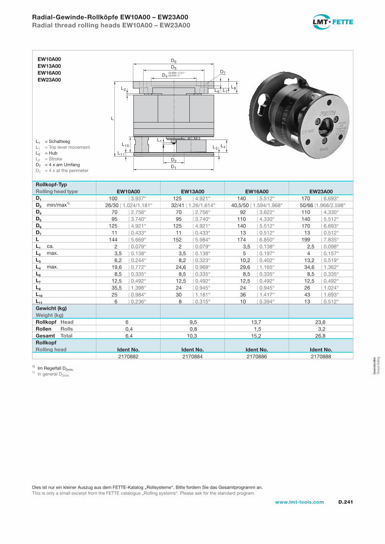
D.241www.lmt-tools.com
Radial-Gewinde-Rollköpfe EW10A00 – EW23A00Radial thread rolling heads EW10A00 – EW23A00
L
L4L3
D7
L1
L11
L10
L2
D2
D1
D4+0,035 | 0.001"+0,010 | 0"
D5
D6
L8L7L6
EW10A00EW13A00EW16A00EW23A00
Rollkopf-TypRolling head typeD1
D2 min/max1)
D4
D5
D6
D7
LL1 ca.L2 max.L3
L4 max.L6
L7
L8
L10
L11
EW10A00 EW13A00 EW16A00 EW23A00 100 | 3.937“ 125 | 4.921“ 140 | 5.512“ 170 | 6.693“ 26/30 | 1.024/1.181“ 32/41 | 1.26/1.614“ 40,5/50 | 1.594/1.968“ 50/66 |1.968/2.598“ 70 | 2.756“ 70 | 2.756“ 92 | 3.622“ 110 | 4.330“ 95 | 3.740“ 95 | 3.740“ 110 | 4.330“ 140 | 5.512“ 125 | 4.921“ 125 | 4.921“ 140 | 5.512“ 170 | 6.693“ 11 | 0.433“ 11 | 0.433“ 13 | 0.512“ 13 | 0.512“ 144 | 5.669“ 152 | 5.984“ 174 | 6.850“ 199 | 7.835“ 2 | 0.079“ 2 | 0.079“ 3,5 | 0.138“ 2,5 | 0.098“ 3,5 | 0.138“ 3,5 | 0.138“ 5 | 0.197“ 4 | 0.157“ 6,2 | 0.244“ 8,2 | 0.323“ 10,2 | 0.402“ 13,2 | 0.519“ 19,6 | 0.772“ 24,6 | 0.968“ 29,6 | 1.165“ 34,6 | 1.362“ 8,5 | 0.335“ 8,5 | 0.335“ 8,5 | 0.335“ 8,5 | 0.335“ 12,5 | 0.492“ 12,5 | 0.492“ 12,5 | 0.492“ 12,5 | 0.492“ 35,5 | 1.398“ 24 | 0.945“ 24 | 0.945“ 26 | 1.024“ 25 | 0.984“ 30 | 1.181“ 36 | 1.417“ 43 | 1.693“ 6 | 0.236“ 8 | 0.315“ 10 | 0.394“ 13 | 0.512“
6 9,5 13,7 23,6 0,4 0,8 1,5 3,2 6,4 10,3 15,2 26,8
Ident No. Ident No. Ident No. Ident No. 2170882 2170884 2170886 2170888
Rollkopf Rolling head
Gewicht (kg)Weight (kg)Rollkopf HeadRollen RollsGesamt Total
1) Im Regelfall D2min.1) In general D2min.
L1 = Schaltweg L1 = Trip lever movementL2 = Hub L2 = StrokeD7 = 4 x am Umfang D7 = 4 x at the perimeter
Dies ist nur ein kleiner Auszug aus dem FETTE-Katalog „Rollsysteme“. Bitte fordern Sie das Gesamtprogramm an.This is only a small excerpt from the FETTE catalogue „Rolling systems“. Please ask for the standard program.
Gew
inde
rolle
n Th
read
Rol
ling
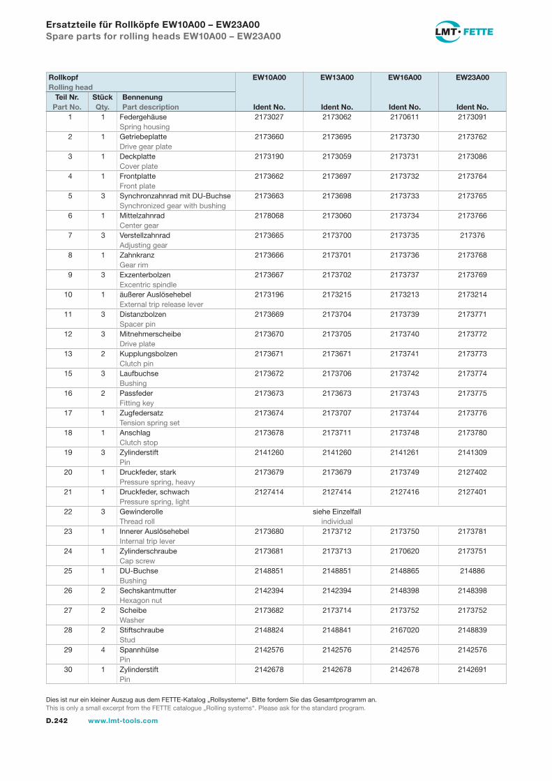
D.242 www.lmt-tools.com
Ersatzteile für Rollköpfe EW10A00 – EW23A00Spare parts for rolling heads EW10A00 – EW23A00
1 1 Federgehäuse 2173027 2173062 2170611 2173091 Spring housing 2 1 Getriebeplatte 2173660 2173695 2173730 2173762 Drive gear plate 3 1 Deckplatte 2173190 2173059 2173731 2173086 Cover plate 4 1 Frontplatte 2173662 2173697 2173732 2173764 Front plate 5 3 Synchronzahnrad mit DU-Buchse 2173663 2173698 2173733 2173765 Synchronized gear with bushing 6 1 Mittelzahnrad 2178068 2173060 2173734 2173766 Center gear 7 3 Verstellzahnrad 2173665 2173700 2173735 217376 Adjusting gear 8 1 Zahnkranz 2173666 2173701 2173736 2173768 Gear rim 9 3 Exzenterbolzen 2173667 2173702 2173737 2173769 Excentric spindle 10 1 äußerer Auslösehebel 2173196 2173215 2173213 2173214 External trip release lever 11 3 Distanzbolzen 2173669 2173704 2173739 2173771 Spacer pin 12 3 Mitnehmerscheibe 2173670 2173705 2173740 2173772 Drive plate 13 2 Kupplungsbolzen 2173671 2173671 2173741 2173773 Clutch pin 15 3 Laufbuchse 2173672 2173706 2173742 2173774 Bushing 16 2 Passfeder 2173673 2173673 2173743 2173775 Fitting key 17 1 Zugfedersatz 2173674 2173707 2173744 2173776 Tension spring set 18 1 Anschlag 2173678 2173711 2173748 2173780 Clutch stop 19 3 Zylinderstift 2141260 2141260 2141261 2141309 Pin 20 1 Druckfeder, stark 2173679 2173679 2173749 2127402 Pressure spring, heavy 21 1 Druckfeder, schwach 2127414 2127414 2127416 2127401 Pressure spring, light 22 3 Gewinderolle siehe Einzelfall Thread roll individual 23 1 Innerer Auslösehebel 2173680 2173712 2173750 2173781 Internal trip lever 24 1 Zylinderschraube 2173681 2173713 2170620 2173751 Cap screw 25 1 DU-Buchse 2148851 2148851 2148865 214886 Bushing 26 2 Sechskantmutter 2142394 2142394 2148398 2148398 Hexagon nut 27 2 Scheibe 2173682 2173714 2173752 2173752 Washer 28 2 Stiftschraube 2148824 2148841 2167020 2148839 Stud 29 4 Spannhülse 2142576 2142576 2142576 2142576 Pin 30 1 Zylinderstift 2142678 2142678 2142678 2142691 Pin
Rollkopf EW10A00 EW13A00 EW16A00 EW23A00Rolling head
Teil Nr. Stück Bennenung Part No. Qty. Part description Ident No. Ident No. Ident No. Ident No.
Dies ist nur ein kleiner Auszug aus dem FETTE-Katalog „Rollsysteme“. Bitte fordern Sie das Gesamtprogramm an.This is only a small excerpt from the FETTE catalogue „Rolling systems“. Please ask for the standard program.
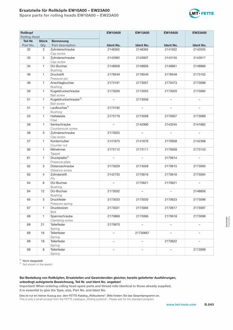
D.243www.lmt-tools.com
Ersatzteile für Rollköpfe EW10A00 – EW23A00Spare parts for rolling heads EW10A00 – EW23A00
32 3 Zylinderschraube 2148362 2148362 2141932 2142035 Cap screw 33 3 Zylinderschraube 2142992 2143007 2143155 2143017 Cap screw 34 1 DU-Buchse 2148858 2148856 2148861 2148866 Bushing 36 1 Druckstift 2178549 2178549 2178548 2173102 Pressure pin 49 1 Anschlagbuchse 2173191 2173057 2170473 2173088 Bushing 50 1 Kugeldruckschraube 2173026 2173055 2173020 2173085 Ball screw 51 1 Kugeldruckschraube1) – 2173056 – – Ball screw 51 1 Laufbuchse1) 2173192 – – – Bushing 53 1 Halteleiste 2173179 2173058 2170957 2173089 Fillet 56 1 Senkschraube – 2142990 2143245 2141882 Countersunk screw 56 3 Zylinderschraube 2173025 – – – Cap screw 57 1 Kontermutter 2141675 2141676 2170958 2142398 Counter nut 60 1 Mitnehmer 2173112 2173111 2170658 2173143 Tappet 61 1 Druckplatte1) – – 2170614 – Pressure plate 62 3 Distanzschraube 2173028 2173028 2170615 2173093 Distance screw 63 4 Zylinderstift 2142735 2170616 2170616 2173094 Pin 64 8 DU-Buchse – 2170621 2170621 – Bushing 64 12 DU-Buchse 2173032 – – 2148856 Bushing 65 3 Druckfeder 2173033 2173033 2170623 2173096 Pressure spring 67 1 Druckbolzen 2173031 2173065 2170617 2173097 Bolt 68 1 Spannschraube 2170869 2173066 2170618 2173098 Clambing screw 69 21 Tellerfeder 2170870 – – – Spring 69 16 Tellerfeder – 21730667 – – Spring 69 18 Tellerfeder – – 2170622 – Spring 69 8 Tellerfeder – – – 2173099 Spring
Rollkopf EW10A00 EW13A00 EW16A00 EW23A00Rolling Head
Teil Nr. Stück Bennenung Part No. Qty. Part description Ident No. Ident No. Ident No. Ident No.
1) Nicht dargestellt1) Not shown in the sketch
Bei Bestellung von Rollköpfen, Ersatzteilen und Gewinderollen gleicher, bereits gelieferter Ausführungen, unbedingt aufsignierte Bezeichnung, Teil Nr. und Ident No. angeben!Important! When ordering rolling head spare parts and thread rolls identical to those already supplied, it is essential to give the Type, size, Part No. and Ident No.
Dies ist nur ein kleiner Auszug aus dem FETTE-Katalog „Rollsysteme“. Bitte fordern Sie das Gesamtprogramm an.This is only a small excerpt from the FETTE catalogue „Rolling systems“. Please ask for the standard program.
Gew
inde
rolle
n Th
read
Rol
ling
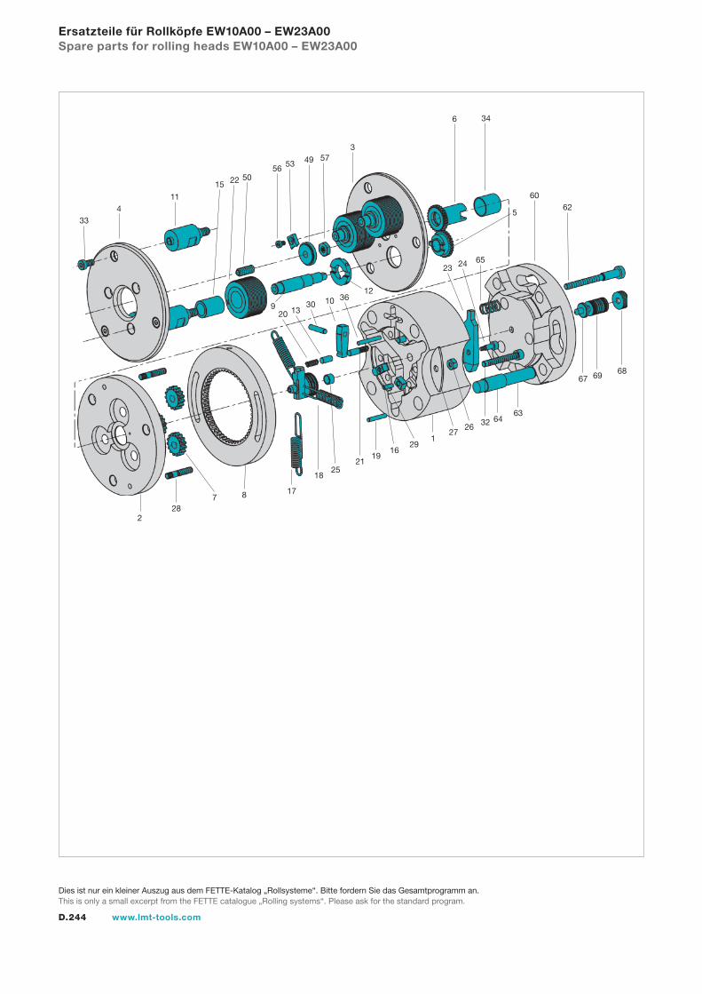
D.244 www.lmt-tools.com
Ersatzteile für Rollköpfe EW10A00 – EW23A00Spare parts for rolling heads EW10A00 – EW23A00
334 5
22
11
5056 53 49 57
3
15
346
6260
652423
12361030
13209
228
7 8 17
1825
2119
1629
127
26 32 6463
67 69 68
Dies ist nur ein kleiner Auszug aus dem FETTE-Katalog „Rollsysteme“. Bitte fordern Sie das Gesamtprogramm an.This is only a small excerpt from the FETTE catalogue „Rolling systems“. Please ask for the standard program.
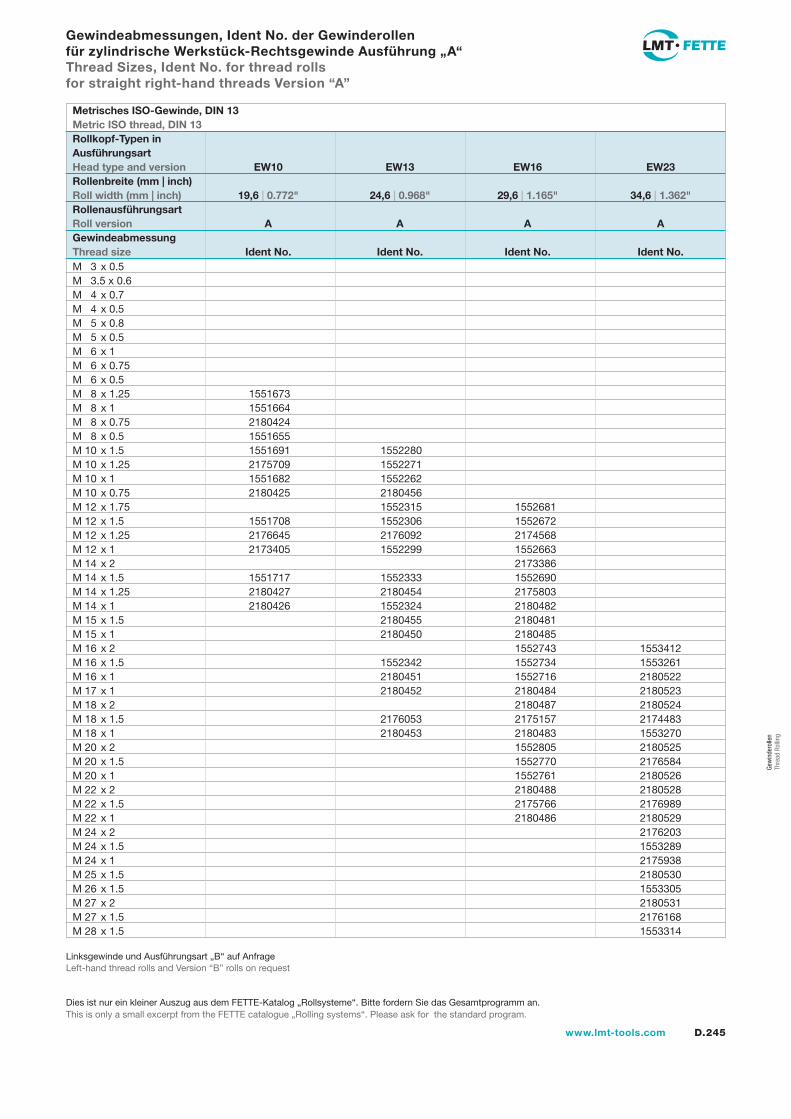
D.245www.lmt-tools.com
Gew
inde
rolle
n Th
read
Rol
ling
Gewindeabmessungen, Ident No. der Gewinderollen für zylindrische Werkstück-Rechtsgewinde Ausführung „A“Thread Sizes, Ident No. for thread rolls for straight right-hand threads Version “A”
M 3 x 0.5M 3.5 x 0.6M 4 x 0.7M 4 x 0.5M 5 x 0.8M 5 x 0.5M 6 x 1M 6 x 0.75M 6 x 0.5M 8 x 1.25 1551673M 8 x 1 1551664M 8 x 0.75 2180424M 8 x 0.5 1551655M 10 x 1.5 1551691 1552280M 10 x 1.25 2175709 1552271M 10 x 1 1551682 1552262M 10 x 0.75 2180425 2180456M 12 x 1.75 1552315 1552681M 12 x 1.5 1551708 1552306 1552672M 12 x 1.25 2176645 2176092 2174568M 12 x 1 2173405 1552299 1552663M 14 x 2 2173386M 14 x 1.5 1551717 1552333 1552690M 14 x 1.25 2180427 2180454 2175803M 14 x 1 2180426 1552324 2180482M 15 x 1.5 2180455 2180481M 15 x 1 2180450 2180485M 16 x 2 1552743 1553412M 16 x 1.5 1552342 1552734 1553261M 16 x 1 2180451 1552716 2180522M 17 x 1 2180452 2180484 2180523M 18 x 2 2180487 2180524M 18 x 1.5 2176053 2175157 2174483M 18 x 1 2180453 2180483 1553270M 20 x 2 1552805 2180525M 20 x 1.5 1552770 2176584M 20 x 1 1552761 2180526M 22 x 2 2180488 2180528M 22 x 1.5 2175766 2176989M 22 x 1 2180486 2180529M 24 x 2 2176203M 24 x 1.5 1553289M 24 x 1 2175938M 25 x 1.5 2180530M 26 x 1.5 1553305M 27 x 2 2180531M 27 x 1.5 2176168M 28 x 1.5 1553314
Metrisches ISO-Gewinde, DIN 13Metric ISO thread, DIN 13Rollkopf-Typen in Ausführungsart Head type and version EW10 EW13 EW16 EW23Rollenbreite (mm | inch)Roll width (mm | inch) 19,6 | 0.772" 24,6 | 0.968" 29,6 | 1.165" 34,6 | 1.362"Rollenausführungsart Roll version A A A AGewindeabmessungThread size Ident No. Ident No. Ident No. Ident No.
Linksgewinde und Ausführungsart „B“ auf AnfrageLeft-hand thread rolls and Version “B” rolls on request
Dies ist nur ein kleiner Auszug aus dem FETTE-Katalog „Rollsysteme“. Bitte fordern Sie das Gesamtprogramm an.This is only a small excerpt from the FETTE catalogue „Rolling systems“. Please ask for the standard program.
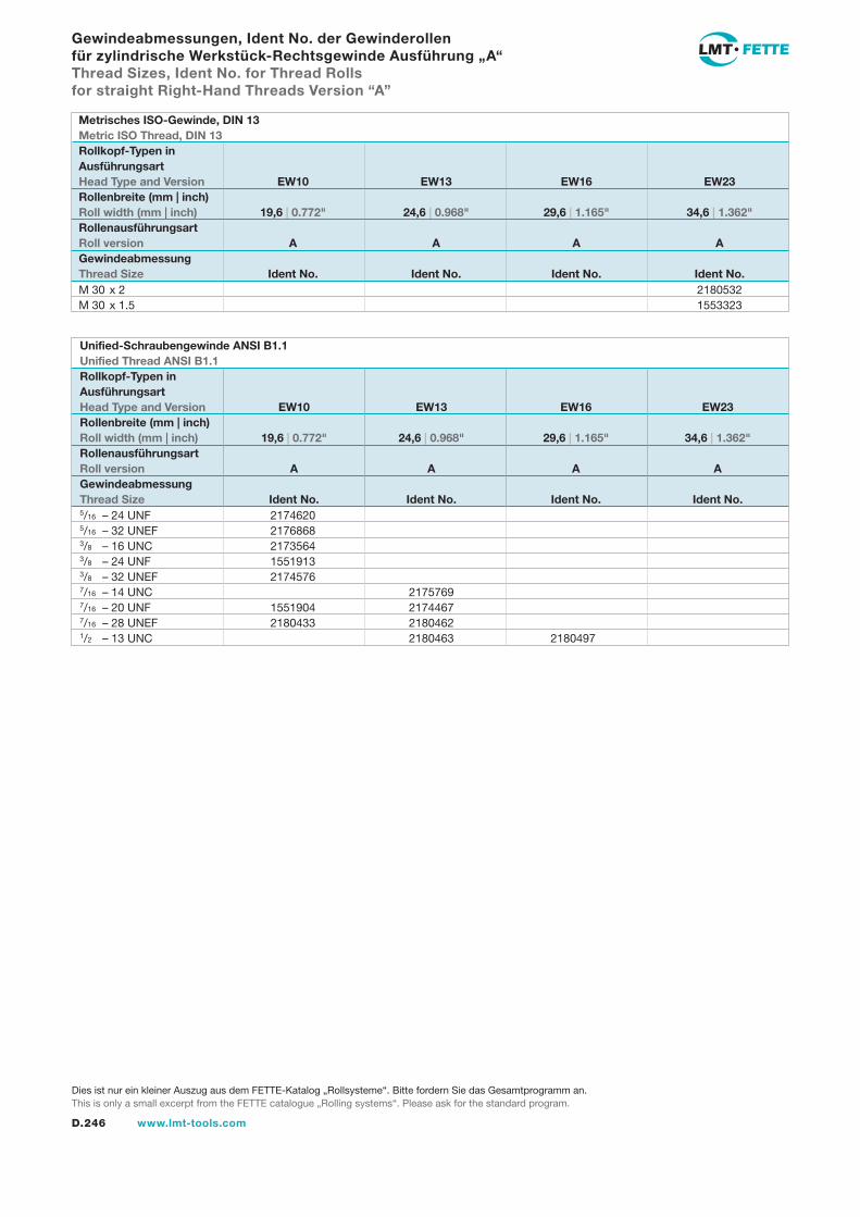
D.246 www.lmt-tools.com
5/16 – 24 UNF 21746205/16 – 32 UNEF 21768683/8 – 16 UNC 21735643/8 – 24 UNF 15519133/8 – 32 UNEF 21745767/16 – 14 UNC 21757697/16 – 20 UNF 1551904 21744677/16 – 28 UNEF 2180433 21804621/2 – 13 UNC 2180463 2180497
M 30 x 2 2180532 M 30 x 1.5 1553323
Gewindeabmessungen, Ident No. der Gewinderollen für zylindrische Werkstück-Rechtsgewinde Ausführung „A“Thread Sizes, Ident No. for Thread Rolls for straight Right-Hand Threads Version “A”
Metrisches ISO-Gewinde, DIN 13Metric ISO Thread, DIN 13Rollkopf-Typen inAusführungsartHead Type and Version EW10 EW13 EW16 EW23Rollenbreite (mm | inch)Roll width (mm | inch) 19,6 | 0.772" 24,6 | 0.968" 29,6 | 1.165" 34,6 | 1.362"Rollenausführungsart Roll version A A A AGewindeabmessungThread Size Ident No. Ident No. Ident No. Ident No.
Unified-Schraubengewinde ANSI B1.1Unified Thread ANSI B1.1Rollkopf-Typen inAusführungsartHead Type and Version EW10 EW13 EW16 EW23Rollenbreite (mm | inch)Roll width (mm | inch) 19,6 | 0.772" 24,6 | 0.968" 29,6 | 1.165" 34,6 | 1.362"Rollenausführungsart Roll version A A A AGewindeabmessungThread Size Ident No. Ident No. Ident No. Ident No.
Dies ist nur ein kleiner Auszug aus dem FETTE-Katalog „Rollsysteme“. Bitte fordern Sie das Gesamtprogramm an.This is only a small excerpt from the FETTE catalogue „Rolling systems“. Please ask for the standard program.
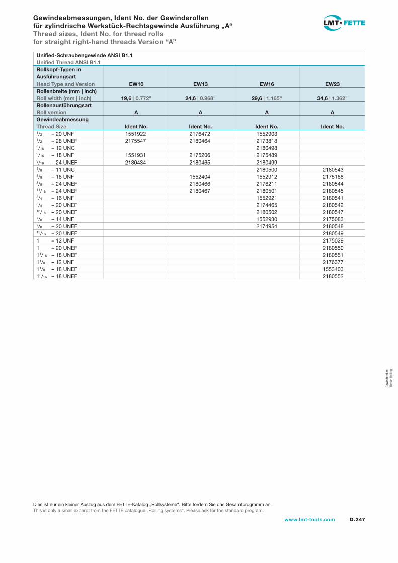
D.247www.lmt-tools.com
1/2 – 20 UNF 1551922 2176472 15529031/2 – 28 UNEF 2175547 2180464 21738189/16 – 12 UNC 21804989/16 – 18 UNF 1551931 2175206 21754899/16 – 24 UNEF 2180434 2180465 21804995/8 – 11 UNC 2180500 21805435/8 – 18 UNF 1552404 1552912 21751885/8 – 24 UNEF 2180466 2176211 218054411/16 – 24 UNEF 2180467 2180501 21805453/4 – 16 UNF 1552921 21805413/4 – 20 UNEF 2174465 218054213/16 – 20 UNEF 2180502 21805477/8 – 14 UNF 1552930 21750837/8 – 20 UNEF 2174954 218054815/16 – 20 UNEF 21805491 – 12 UNF 21750291 – 20 UNEF 218055011/16 – 18 UNEF 218055111/8 – 12 UNF 217637711/8 – 18 UNEF 155340313/16 – 18 UNEF 2180552
Gewindeabmessungen, Ident No. der Gewinderollen für zylindrische Werkstück-Rechtsgewinde Ausführung „A“Thread sizes, Ident No. for thread rolls for straight right-hand threads Version “A”
Unified-Schraubengewinde ANSI B1.1Unified Thread ANSI B1.1Rollkopf-Typen inAusführungsartHead Type and Version EW10 EW13 EW16 EW23Rollenbreite (mm | inch)Roll width (mm | inch) 19,6 | 0.772" 24,6 | 0.968" 29,6 | 1.165" 34,6 | 1.362"RollenausführungsartRoll version A A A AGewindeabmessungThread Size Ident No. Ident No. Ident No. Ident No.
Dies ist nur ein kleiner Auszug aus dem FETTE-Katalog „Rollsysteme“. Bitte fordern Sie das Gesamtprogramm an.This is only a small excerpt from the FETTE catalogue „Rolling systems“. Please ask for the standard program.
Gew
inde
rolle
n Th
read
Rol
ling
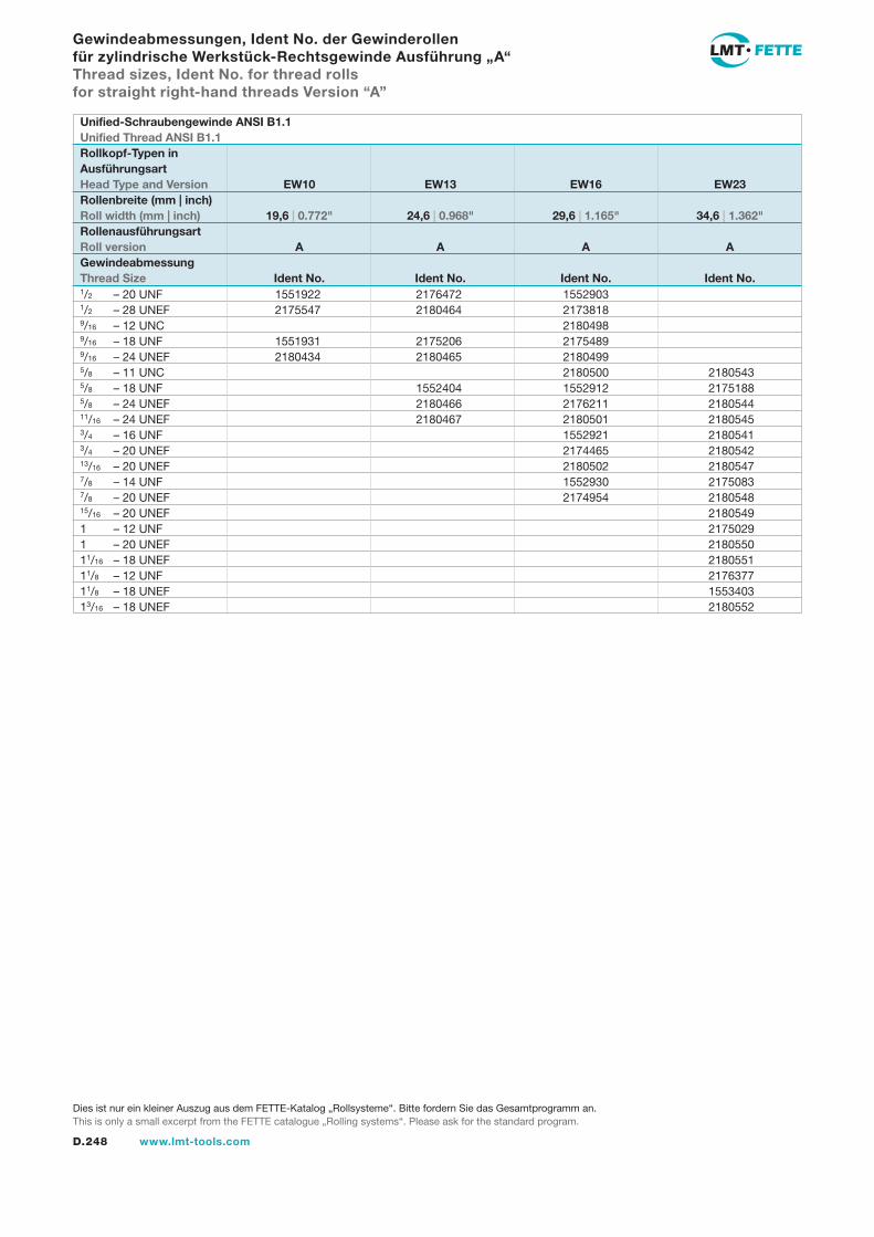
D.248 www.lmt-tools.com
1/2 – 20 UNF 1551922 2176472 15529031/2 – 28 UNEF 2175547 2180464 21738189/16 – 12 UNC 21804989/16 – 18 UNF 1551931 2175206 21754899/16 – 24 UNEF 2180434 2180465 21804995/8 – 11 UNC 2180500 21805435/8 – 18 UNF 1552404 1552912 21751885/8 – 24 UNEF 2180466 2176211 218054411/16 – 24 UNEF 2180467 2180501 21805453/4 – 16 UNF 1552921 21805413/4 – 20 UNEF 2174465 218054213/16 – 20 UNEF 2180502 21805477/8 – 14 UNF 1552930 21750837/8 – 20 UNEF 2174954 218054815/16 – 20 UNEF 21805491 – 12 UNF 21750291 – 20 UNEF 218055011/16 – 18 UNEF 218055111/8 – 12 UNF 217637711/8 – 18 UNEF 155340313/16 – 18 UNEF 2180552
Gewindeabmessungen, Ident No. der Gewinderollen für zylindrische Werkstück-Rechtsgewinde Ausführung „A“Thread sizes, Ident No. for thread rolls for straight right-hand threads Version “A”
Unified-Schraubengewinde ANSI B1.1Unified Thread ANSI B1.1Rollkopf-Typen inAusführungsartHead Type and Version EW10 EW13 EW16 EW23Rollenbreite (mm | inch)Roll width (mm | inch) 19,6 | 0.772" 24,6 | 0.968" 29,6 | 1.165" 34,6 | 1.362"RollenausführungsartRoll version A A A AGewindeabmessungThread Size Ident No. Ident No. Ident No. Ident No.
Dies ist nur ein kleiner Auszug aus dem FETTE-Katalog „Rollsysteme“. Bitte fordern Sie das Gesamtprogramm an.This is only a small excerpt from the FETTE catalogue „Rolling systems“. Please ask for the standard program.
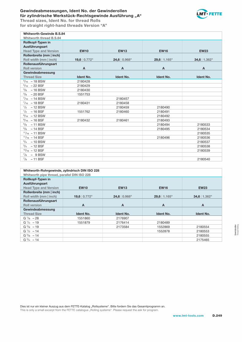
D.249www.lmt-tools.com
Gew
inde
rolle
n Th
read
Rol
ling
G 1/8 – 28 1551860 2176907G 1/4 – 19 1551879 2176414 2180489G 3/8 – 19 2173584 1552869 2180554G 1/2 – 14 1552878 2180553G 5/8 – 14 2180555G 3/4 – 14 2175465
Gewindeabmessungen, Ident No. der Gewinderollen für zylindrische Werkstück-Rechtsgewinde Ausführung „A“Thread sizes, Ident No. for thread Rolls for straight right-hand threads Version “A”
5/16 – 18 BSW 21804285/16 – 22 BSF 21804293/8 – 16 BSW 21804303/8 – 20 BSF 15517537/16 – 14 BSW 21804577/16 – 18 BSF 2180431 21804581/2 – 12 BSW 2180459 21804901/2 – 16 BSF 1551762 2180460 21804919/16 – 12 BSW 21804929/16 – 16 BSF 2180432 2180461 21804935/8 – 11 BSW 2180494 21805335/8 – 14 BSF 2180495 218053411/16 – 11 BSW 218053511/16 – 14 BSF 2180496 21805363/4 – 10 BSW 21805373/4 – 12 BSF 218053813/16 – 12 BSF 21805397/8 – 9 BSW 7/8 – 11 BSF 2180540
Whitworth-Gewinde B.S.84Whitworth thread B.S.84Rollkopf-Typen inAusführungsart Head Type and Version EW10 EW13 EW16 EW23Rollenbreite (mm | inch)Roll width (mm | inch) 19,6 | 0.772" 24,6 | 0.968" 29,6 | 1.165" 34,6 | 1.362"RollenausführungsartRoll version A A A AGewindeabmessungThread Size Ident No. Ident No. Ident No. Ident No.
Whitworth-Rohrgewinde, zylindrisch DIN ISO 228Whitworth pipe thread, parallel DIN ISO 228Rollkopf-Typen inAusführungsartHead Type and Version EW10 EW13 EW16 EW23Rollenbreite (mm | inch)Roll width (mm | inch) 19,6 | 0.772" 24,6 | 0.968" 29,6 | 1.165" 34,6 | 1.362"RollenausführungsartRoll version A A A AGewindeabmessungThread Size Ident No. Ident No. Ident No. Ident No.
Dies ist nur ein kleiner Auszug aus dem FETTE-Katalog „Rollsysteme“. Bitte fordern Sie das Gesamtprogramm an.This is only a small excerpt from the FETTE catalogue „Rolling systems“. Please request the ask for program.
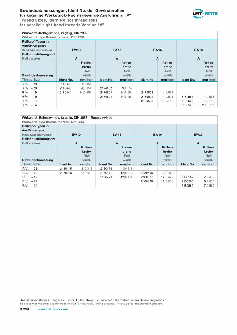
D.250 www.lmt-tools.com
Whitworth-Rohrgewinde, kegelig, DIN 3858 – RegelgewindeWhitworth pipe thread, tapered, DIN 3858Rollkopf-Typen inAusführungsartHead type and version EW10 EW13 EW16 EW23Rollenausführungsart Roll version A A A A Rollen- Rollen- Rollen- Rollen- breite breite breite breite Roll Roll Roll RollGewindeabmessung width width width widthThread Size Ident No. mm | inch Ident No. mm | inch Ident No. mm | inch Ident No. mm | inch
Whitworth-Rohrgewinde, kegelig, DIN 2999Whitworth pipe thread, tapered, DIN 2999Rollkopf-Typen inAusführungsartHead type and version EW10 EW13 EW16 EW23Rollenausführungsart Roll version A A A A Rollen- Rollen- Rollen- Rollen- breite breite breite breite Roll Roll Roll RollGewindeabmessung width width width widthThread Size Ident No. mm | inch Ident No. mm | inch Ident No. mm | inch Ident No. mm | inch
R 1/8 – 28 2180445 8 | 0.315 2180476 8 | 0.315R 1/4 – 19 2180446 12 | 0.472 2180477 12 | 0.472 2180506 12 | 0.472R 3/8 – 19 2180478 12 | 0.472 2180507 12 | 0.472 2180567 12 | 0.472R 1/2 – 14 2180508 16 | 0.630 2180568 16 | 0.630R 3/4 – 14 2180569 17 | 0.669
R 1/16 – 28 2180442 9 | 0.354R 1/8 – 28 2180443 9 | 0.354 2174802 9 | 0.354R 1/4 – 19 2180444 14 | 0.551 2174803 14 | 0.551 2170503 14 | 0.551R 3/8 – 19 2174804 14 | 0.551 2180504 14 | 0.551 2180565 14 | 0.551R 1/2 – 14 2180505 19 | 0.748 2180564 19 | 0.748R 3/4 – 14 2180566 20 | 0.787
Gewindeabmessungen, Ident No. der Gewinderollen für kegelige Werkstück-Rechtsgewinde Ausführung „A“Thread Sizes, Ident No. for thread rolls for parallel right-hand threads Version “A”
Dies ist nur ein kleiner Auszug aus aus dem FETTE-Katalog „Rollsysteme“. Bitte fordern Sie das Gesamtprogramm an.This is only only a small excerpt from the FETTE catalogue „Rolling systems“. Please ask for the standard program.
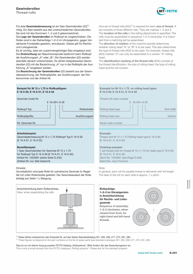
D.251www.lmt-tools.com
Gew
inde
rolle
n Th
read
Rol
ling
GewinderollenThread rolls
Für jede Gewindeabmessung ist ein Satz Gewinderollen (22)1) nötig. Ein Satz besteht aus drei unterschiedlichen Gewinderollen. Sie sind mit den Nummern 1, 2 und 3 gekennzeichnet.Die Lage der Gewinderollen im Rollkopf ist vorgeschrieben. Die Rollen sind in der Reihenfolge 1–2–3 im Uhrzeigersinn, gegen Vor-derkante Frontplatte gesehen, einzubauen. Dieses gilt für Rechts- und Linksgewinde.Es ist wichtig, dass ein zusammengehöriger Satz eingebaut wird.Die Drehrichtung der Maschinenspindel bestimmt beim Rollkopf die Ausführungsart „A“ oder „B“. Die Gewinderollen (22) werden ebenfalls danach unterschieden. Es dürfen beispielsweise Gewin-derollen (22) mit der Bezeichnung „A“ nur in die Rollköpfe der Aus-führung „A“ eingebaut werden.Die Bezeichnung der Gewinderollen (22) besteht aus der Gewin-debezeichnung, der Rollkopfgröße, der Ausführungsart, der Rol-lennummer und der Artikel-Nr.
One set of thread rolls (#22)1) is required for each size of thread. A set consists of three different rolls. They are marked 1, 2 and 3.The location of the rolls in the rolling attachment is specified. The rolls must be assembled in sequence 1–2–3 clockwise. It is impor-tant that a matching set be assembled.The direction of rotation of the machine spindle determines whether rolling head “A” or “B” is to be used. This also determines the type of thread rolls (#22) to be used. For example, thread rolls (#22) marked “A” can only be assembled in a version “A” rolling head.The identification marking of the thread rolls (#22) consists of the thread identification, the size of rolling head, the type of rolling head and the roll number.
Einbaufolge: 1–2–3 im Uhrzeigersinn in Ansichtsrichtung für Rechts- und Links-gewindeSequence of assembly: 1–2–3 clockwise, when viewed from front, for right-hand and left-hand threads
Ansichtsrichtung beim RolleneinbauView, when assembling the rolls
Hinweis:Grundsätzlich wird jede Rolle für zylindrische Gewinde im Regel-fall mit voller Rollenbreite geliefert. Der Gewindeauslauf der Rolle beträgt pro Seite 1 x Steigung.
2
1
3
Beispiel für M 12 x 1,75 in RollkopftypenE 16 A 00, E 16 A 01, E 16 A 02
Gewinde-Code-Nr.E 16–001–A 29
Rollkopf-Typ Rollenbreite
Rollkopfgröße Ausführungsart
lfd. Gewinde-Nr.
Arbeitsbeispiel:Gewindeabmessung M 12 x 1,75 Rollkopf-Typ E 16 A 00 (E 16 A 01, E 16 A 02)
Bestellbeispiel:1 Satz Gewinderollen für Gewinde M 12 x 1,75für Rollkopf-Typ E 16 A 00 (E 16 A 01, E 16 A 02)Artikel-Nr. 1552681 (siehe Seite D.245)(Artikel-Nr. nur, falls bekannt)
Example for M 12 x 1.75 on rolling head typesE 16 A 00, E 16 A 01, E 16 A 02
Thread roll code numberE 16–001–A 29
Rolling head type Roll width
Rolling head size Version
Serial code number
Example:Thread size M 12 x 1.75 Rolling head type E 16 A 00 (E 16 A 01, E 16 A 02)
Ordering example:1 set thread rolls for thread M 12 x 1.75 for head type E 16 A 00 (E 16 A 01, E 16 A 02)Ident No. 1552681 (see Page D.245)(Ident No. only if known)
1) Diese Zahlen entsprechen den Ersatzteil-Nr. auf den Seiten Standardkatalog 261, 265, 269, 271, 273, 281, 285.1) These figures correspond to the part numbers on the list of spare parts (see standard catalogue 261, 265, 269, 271, 273, 281, 285.
Note:In general, each roll for parallel thread is delivered with full length. The lead of the roll on each side is approx. 1 x pitch.
Dies ist nur ein kleiner Auszug ausdem FETTE-Katalog „Rollsysteme“. Bitte fordern Sie das Gesamtprogramm an.This is only a small excerpt from the FETTE catalogue „Rolling systems“. Please ask for the standard program.
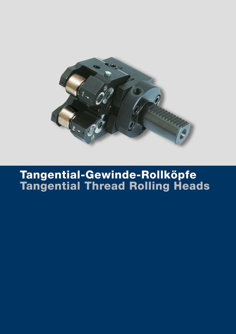
www.lmt-tools.comA.D.252
Tangential-Gewinde-RollköpfeTangential Thread Rolling Heads
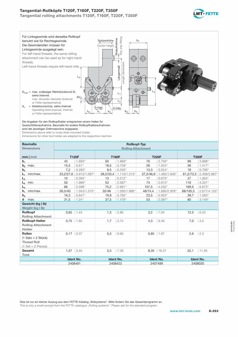
D.253www.lmt-tools.com
Gew
inde
rolle
n Th
read
Rol
ling
Tangential-Rollköpfe T120F, T160F, T220F, T350FTangential rolling attachments T120F, T160F, T220F, T350F
Ident No. Ident No. Ident No. Ident No. 2408491 2408423 2407499 2408020
Spitzenhöhe
Center height
Nut
aufn
ahm
e
Key
way
fitt
ing
Läng
enm
aß
Leng
ht d
imen
sion
b2h2h1h2
D max. d max.
L2
L3
AVL1
b1
b3
L4
Die Angaben für den Rollkopfhalter entsprechen einem Halter fürQuerschlittenaufnahme. Baumaße für andere Rollkopfhalteraufnahmen sind der jeweiligen Drehmaschine angepasst.Dimensions above refer to cross slide mounted holder.Dimensions for other tool holder are adapted to the respective machine.
Dmax = max. zulässiger Werkstückbund-Ø, siehe Internet. max. shoulder diameter (Internet or Fette representative)Av = Arbeitsvorschub, siehe Internet Operating feed (manual, Internet or Fette representative)
Gewicht (kg | lb)Weight (kg | lb)Rollkopf Rolling AttachmentRollkopf-Halter Rolling Attachment HolderRollen (1 Satz = 2 Stück)Thread Roll (1 Set = 2 Pieces)GesamtTotal
Für Linksgewinde wird derselbe Rollkopf benutzt wie für Rechtsgewinde.Die Gewinderollen müssen für Linksgewinde ausgelegt sein.For left-hand threads, the same rolling attachment can be used as for right-hand threads. Left-hand threads require left-hand rolls.
BaumaßeDimensions
mm | inchb1
b2 max.b3
L1 min/max.L2
L3 min.L4
h1 min/max.h2
d max.
Rollkopf-Typ Rolling Attachment
T120F T160F T220F T350F 43 | 1.693“ 50 | 1.969“ 70 | 2.756“ 99 | 3.898“ 15,5 | 0.61“ 18,5 | 0.728“ 26 | 1.024“ 36 | 1.417“ 7,2 | 0.283“ 8,5 | 0.335“ 13,3 | 0.524“ 18 | 0.709“ 23,2/27,6 | 0.913/1.087“ 28,2/33,4 | 1.110/1.315“ 37,2/46,9 | 1.465/1.846“ 61,2/73,3 | 2.409/2.887“ 10 | 0.394“ 13 | 0.512“ 17 | 0.670“ 27 | 1.063“ 50 | 1.969“ 53 | 2.087“ 74 | 2.913“ 110 | 4.331“ 66 | 2.598“ 75,2 | 2.961“ 107,5 | 4.232“ 169,5 | 6.673“ 26,5/40 | 1.043/1.575“ 32/48 | 1.260/1.890“ 48/74,4 | 1.890/2.929“ 68/105,5 | 2.677/4.155“ 16,3 | 0.641“ 19,9 | 0.783“ 23,5 | 0.925“ 39,7 | 1.563“ 31,5 | 1.24“ 37,5 | 1.476“ 53 | 2.087“ 80 | 3.149“
0,65 | 1.43 1,3 | 2.86 3,2 | 7.04 12,5 | 6.25
0,75 | 1.65 1,7 | 3.74 4,3 | 9.46 7,0 | 3.5
0,17 | 0.37 0,3 | 0.66 0,85 | 1.87 2,6 | 2.3
1,57 | 3.45 3,3 | 7.26 8,35 | 18.37 22,1 | 11.05
Dies ist nur ein kleiner Auszug aus dem FETTE-Katalog „Rollsysteme“. Bitte fordern Sie das Gesamtprogramm an.This is only a small excerpt from the FETTE catalogue „Rolling systems“. Please ask for the standard program.
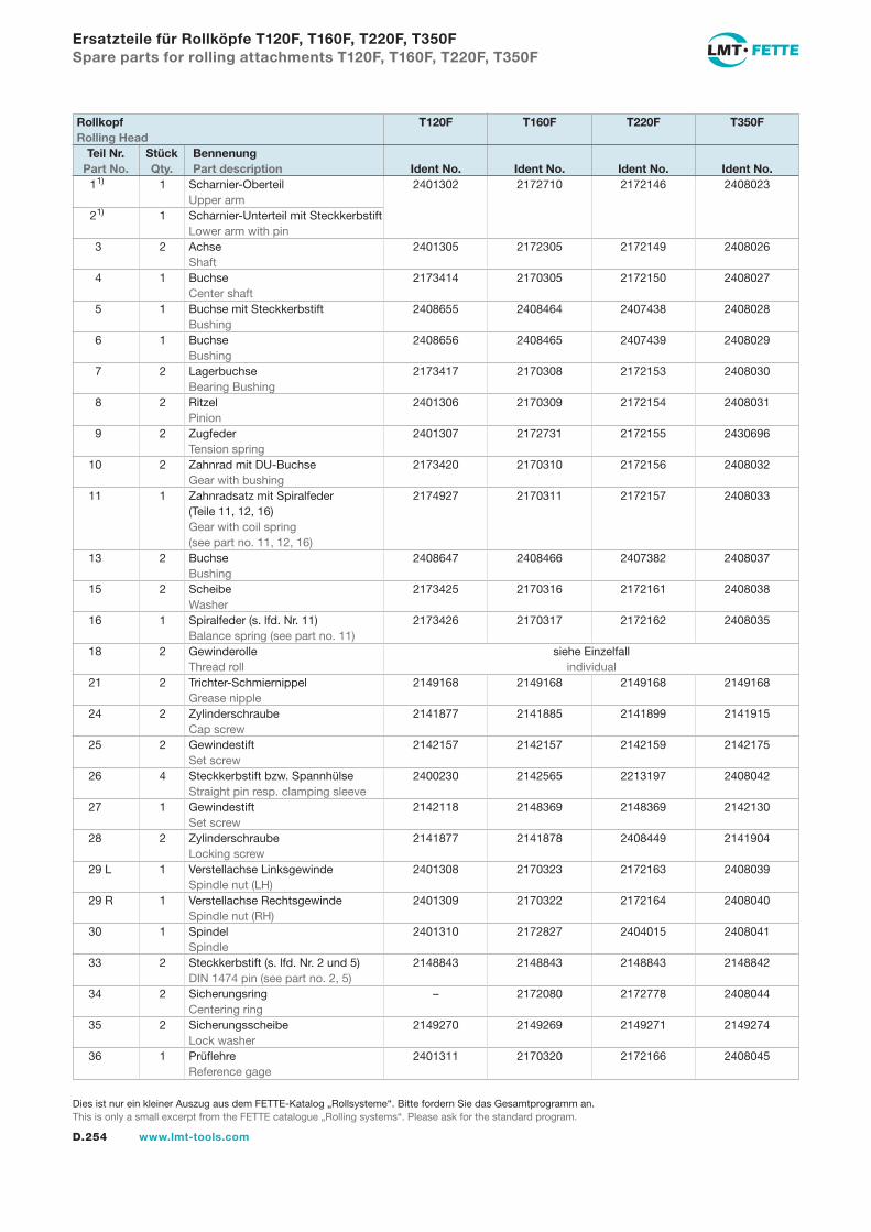
D.254 www.lmt-tools.com
Ersatzteile für Rollköpfe T120F, T160F, T220F, T350FSpare parts for rolling attachments T120F, T160F, T220F, T350F
1 1) 1 Scharnier-Oberteil 2401302 2172710 2172146 2408023 Upper arm 2 1) 1 Scharnier-Unterteil mit Steckkerbstift Lower arm with pin 3 2 Achse 2401305 2172305 2172149 2408026 Shaft 4 1 Buchse 2173414 2170305 2172150 2408027 Center shaft 5 1 Buchse mit Steckkerbstift 2408655 2408464 2407438 2408028 Bushing 6 1 Buchse 2408656 2408465 2407439 2408029 Bushing 7 2 Lagerbuchse 2173417 2170308 2172153 2408030 Bearing Bushing 8 2 Ritzel 2401306 2170309 2172154 2408031 Pinion 9 2 Zugfeder 2401307 2172731 2172155 2430696 Tension spring 10 2 Zahnrad mit DU-Buchse 2173420 2170310 2172156 2408032 Gear with bushing 11 1 Zahnradsatz mit Spiralfeder 2174927 2170311 2172157 2408033 (Teile 11, 12, 16) Gear with coil spring (see part no. 11, 12, 16) 13 2 Buchse 2408647 2408466 2407382 2408037 Bushing 15 2 Scheibe 2173425 2170316 2172161 2408038 Washer 16 1 Spiralfeder (s. lfd. Nr. 11) 2173426 2170317 2172162 2408035 Balance spring (see part no. 11) 18 2 Gewinderolle siehe Einzelfall Thread roll individual 21 2 Trichter-Schmiernippel 2149168 2149168 2149168 2149168 Grease nipple 24 2 Zylinderschraube 2141877 2141885 2141899 2141915 Cap screw 25 2 Gewindestift 2142157 2142157 2142159 2142175 Set screw 26 4 Steckkerbstift bzw. Spannhülse 2400230 2142565 2213197 2408042 Straight pin resp. clamping sleeve 27 1 Gewindestift 2142118 2148369 2148369 2142130 Set screw 28 2 Zylinderschraube 2141877 2141878 2408449 2141904 Locking screw 29 L 1 Verstellachse Linksgewinde 2401308 2170323 2172163 2408039 Spindle nut (LH) 29 R 1 Verstellachse Rechtsgewinde 2401309 2170322 2172164 2408040 Spindle nut (RH) 30 1 Spindel 2401310 2172827 2404015 2408041 Spindle 33 2 Steckkerbstift (s. lfd. Nr. 2 und 5) 2148843 2148843 2148843 2148842 DIN 1474 pin (see part no. 2, 5) 34 2 Sicherungsring – 2172080 2172778 2408044 Centering ring 35 2 Sicherungsscheibe 2149270 2149269 2149271 2149274 Lock washer 36 1 Prüflehre 2401311 2170320 2172166 2408045 Reference gage
Rollkopf T120F T160F T220F T350FRolling Head
Teil Nr. Stück Bennenung Part No. Qty. Part description Ident No. Ident No. Ident No. Ident No.
Dies ist nur ein kleiner Auszug aus dem FETTE-Katalog „Rollsysteme“. Bitte fordern Sie das Gesamtprogramm an.This is only a small excerpt from the FETTE catalogue „Rolling systems“. Please ask for the standard program.
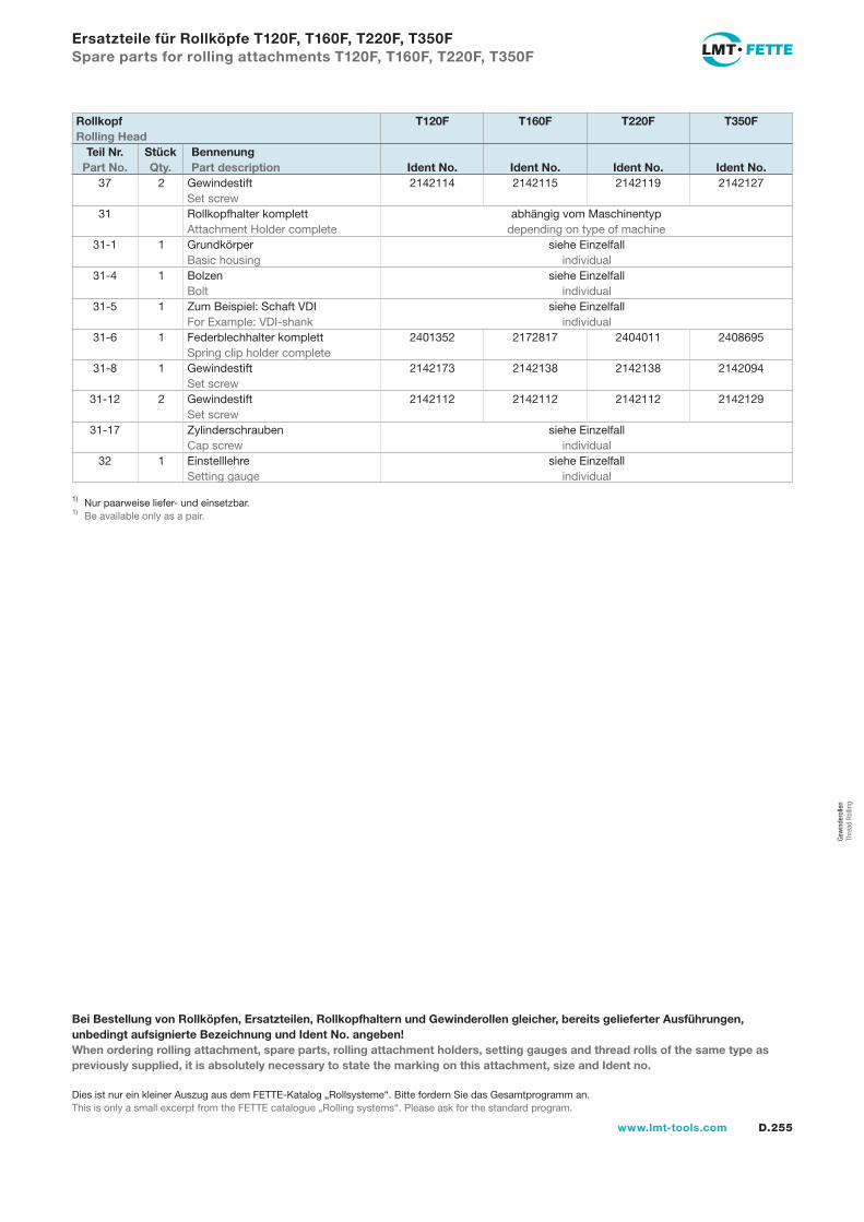
D.255www.lmt-tools.com
Gew
inde
rolle
n Th
read
Rol
ling
Ersatzteile für Rollköpfe T120F, T160F, T220F, T350FSpare parts for rolling attachments T120F, T160F, T220F, T350F
37 2 Gewindestift 2142114 2142115 2142119 2142127 Set screw 31 Rollkopfhalter komplett abhängig vom Maschinentyp Attachment Holder complete depending on type of machine 31-1 1 Grundkörper siehe Einzelfall Basic housing individual 31-4 1 Bolzen siehe Einzelfall Bolt individual 31-5 1 Zum Beispiel: Schaft VDI siehe Einzelfall For Example: VDI-shank individual 31-6 1 Federblechhalter komplett 2401352 2172817 2404011 2408695 Spring clip holder complete 31-8 1 Gewindestift 2142173 2142138 2142138 2142094 Set screw 31-12 2 Gewindestift 2142112 2142112 2142112 2142129 Set screw 31-17 Zylinderschrauben siehe Einzelfall Cap screw individual 32 1 Einstelllehre siehe Einzelfall Setting gauge individual
Bei Bestellung von Rollköpfen, Ersatzteilen, Rollkopfhaltern und Gewinderollen gleicher, bereits gelieferter Ausführungen, unbedingt aufsignierte Bezeichnung und Ident No. angeben!When ordering rolling attachment, spare parts, rolling attachment holders, setting gauges and thread rolls of the same type as previously supplied, it is absolutely necessary to state the marking on this attachment, size and Ident no.
Rollkopf T120F T160F T220F T350FRolling Head
Teil Nr. Stück Bennenung Part No. Qty. Part description Ident No. Ident No. Ident No. Ident No.
1) Nur paarweise liefer- und einsetzbar.1) Be available only as a pair.
Dies ist nur ein kleiner Auszug aus dem FETTE-Katalog „Rollsysteme“. Bitte fordern Sie das Gesamtprogramm an.This is only a small excerpt from the FETTE catalogue „Rolling systems“. Please ask for the standard program.
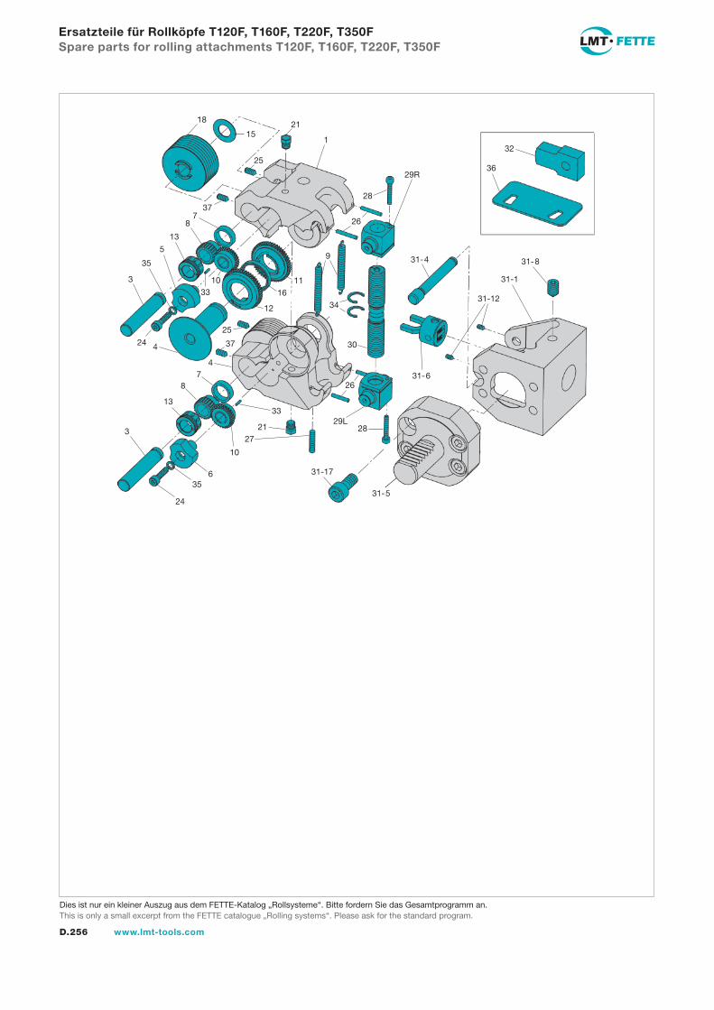
D.256 www.lmt-tools.com
Ersatzteile für Rollköpfe T120F, T160F, T220F, T350FSpare parts for rolling attachments T120F, T160F, T220F, T350F
29R
28
26
1
21
25
15
18
37
9
1116
12
78
13
5
35
3 1033
34
31-4
25
3724 4
47
8
13
3
33
2127
10
6
30
26
29L28
31-17
35
2431-5
31-6
31-12
31-1
31-8
32
36
Dies ist nur ein kleiner Auszug aus dem FETTE-Katalog „Rollsysteme“. Bitte fordern Sie das Gesamtprogramm an.This is only a small excerpt from the FETTE catalogue „Rolling systems“. Please ask for the standard program.
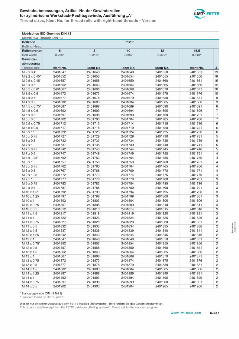
D.257www.lmt-tools.com
Gew
inde
rolle
n Th
read
Rol
ling
2401647 2401648 2401649 2401650 2401651 19 2401652 2401653 2401654 2401655 2401656 18 2401657 2401658 2401659 2401660 2401661 15 2401662 2401663 2401664 2401665 2401666 12 2401667 2401668 2401669 2401670 2401671 10 2401672 2401673 2401674 2401675 2401676 10 2401677 2401678 2401679 2401680 2401681 9 2401682 2401683 2401684 2401685 2401686 9 2401687 2401688 2401689 2401690 2401691 8 2401692 2401693 2401694 2401695 2401696 7 2401697 2401698 2401699 2401700 2401701 7 2401702 2401703 2401704 2401705 2401706 7 2401712 2401713 2401714 2401715 2401716 6 2401717 2401718 2401719 2401720 2401721 6 2401722 2401723 2401724 2401725 2401726 6 2401727 2401728 2401729 2401730 2401731 5 2401732 2401733 2401734 2401735 2401736 5 2401737 2401738 2401739 2401740 2401741 5 2401742 2401743 2401744 2401745 2401746 5 2401747 2401748 2401749 2401750 2401751 4 2401752 2401753 2401754 2401755 2401756 4 2401757 2401758 2401759 2401760 2401761 4 2401762 2401763 2401764 2401765 2401766 4 2401767 2401768 2401769 2401770 2401771 4 2401772 2401773 2401774 2401775 2401776 4 2401777 2401778 2401779 2401780 2401781 3 2401782 2401783 2401784 2401785 2401786 3 2401787 2401788 2401789 2401790 2401791 3 2401792 2401793 2401794 2401795 2401796 3 2401797 2401798 2401799 2401800 2401801 3 2401802 2401803 2401804 2401805 2401806 3 2401807 2401808 2401809 2401810 2401811 3 2401812 2401813 2401814 2401815 2401816 3 2401817 2401818 2401819 2401820 2401821 3 2401822 2401823 2401824 2401825 2401826 3 2401827 2401828 2401829 2401830 2401831 2 2401832 2401833 2401834 2401835 2401836 2 2401837 2401838 2401839 2401840 2401841 2 2401842 2401843 2401844 2401845 2401846 2 2401847 2401848 2401849 2401850 2401851 2 2401852 2401853 2401854 2401855 2401856 2 2401857 2401858 2401859 2401860 2401861 2 2401862 2401863 2401864 2401865 2401866 2 2401867 2401868 2401869 2401870 2401871 2 2401872 2401873 2401874 2401875 2401876 2 2401877 2401878 2401879 2401880 2401881 2 2401882 2401883 2401884 2401885 2401886 2 2401887 2401888 2401889 2401890 2401891 2 2401892 2401893 2401894 2401895 2401896 2 2401897 2401898 2401899 2401900 2401901 2 2401902 2401903 2401904 2401905 2401906 2
M 2 x 0,4* M 2,2 x 0,45* M 2,5 x 0,45* M 3 x 0,5* M 3,5 x 0,6* M 3,5 x 0,5 M 4 x 0,7* M 4 x 0,5 M 4,5 x 0,75* M 4,5 x 0,5 M 5 x 0,8* M 5 x 0,5 M 5,5 x 0,75 M 5,5 x 0,5 M 6 x 1* M 6 x 0,75 M 6 x 0,5 M 7 x 1 M 7 x 0,75 M 7 x 0,5 M 8 x 1,25* M 8 x 1 M 8 x 0,75 M 8 x 0,5 M 9 x 1,25 M 9 x 1 M 9 x 0,75 M 9 x 0,5 M 10 x 1,5* M 10 x 1,25 M 10 x 1 M 10 x 0,75 M 10 x 0,5 M 11 x 1,5 M 11 x 1 M 11 x 0,75 M 11 x 0,5 M 12 x 1,5 M 12 x 1,25 M 12 x 1M 12 x 0,75*M 12 x 0,5M 13 x 1,5M 13 x 1M 13 x 0,75M 13 x 0,5M 14 x 1,5M 14 x 1,25M 14 x 1M 14 x 0,75M 14 x 0,5
Gewindeabmessungen, Artikel-Nr. der Gewinderollen für zylindrische Werkstück-Rechtsgewinde, Ausführung „A“Thread sizes, Ident No. for thread rolls with right-hand threads – Version
Metrisches ISO-Gewinde DIN 13Metric ISO Threads DIN 13Rollkopf T120FRolling HeadRollenbreiten 6 8 10 12 15,5Roll width 0.236" 0.315" 0.394" 0.472" 0.610"Gewinde-abmessungThread size Ident No. Ident No. Ident No. Ident No. Ident No. Z
* Standardgewinde (DIN 13 Teil 1) * Standard thread (to DIN 13 part 1)
Dies ist nur ein kleiner Auszug aus dem FETTE-Katalog „Rollsysteme“. Bitte fordern Sie das Gesamtprogramm an.This is only a small excerpt from the FETTE catalogue „Rolling systems“. Please ask for the standard program.
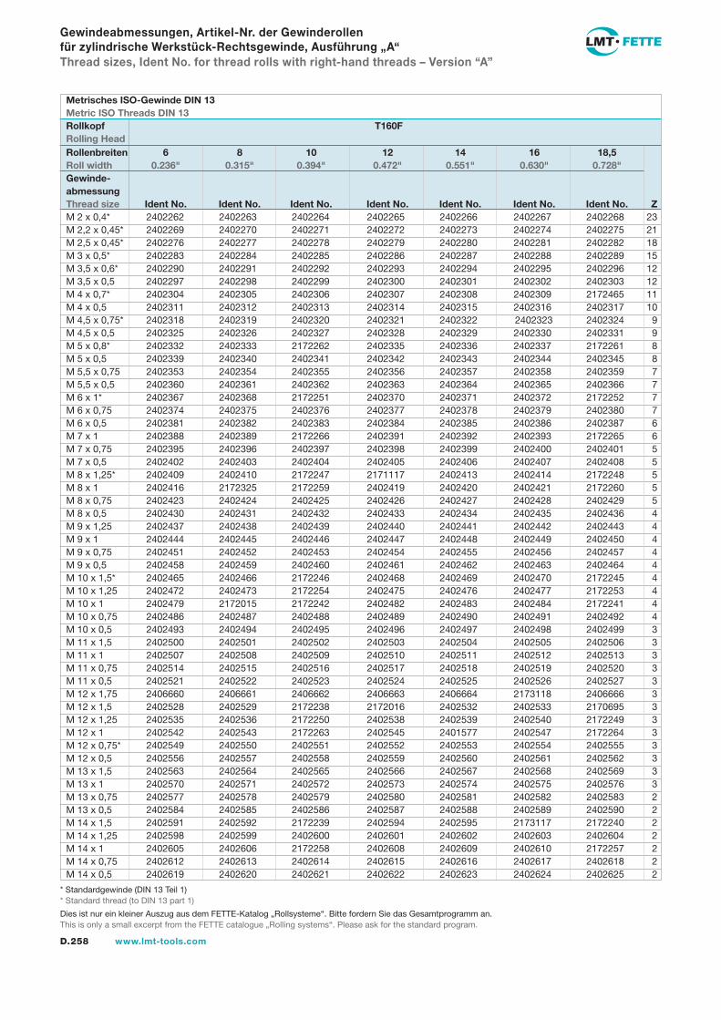
D.258 www.lmt-tools.com
M 2 x 0,4* M 2,2 x 0,45* M 2,5 x 0,45* M 3 x 0,5* M 3,5 x 0,6* M 3,5 x 0,5 M 4 x 0,7* M 4 x 0,5 M 4,5 x 0,75* M 4,5 x 0,5 M 5 x 0,8* M 5 x 0,5 M 5,5 x 0,75 M 5,5 x 0,5 M 6 x 1* M 6 x 0,75 M 6 x 0,5 M 7 x 1 M 7 x 0,75 M 7 x 0,5 M 8 x 1,25* M 8 x 1 M 8 x 0,75 M 8 x 0,5 M 9 x 1,25 M 9 x 1 M 9 x 0,75 M 9 x 0,5 M 10 x 1,5* M 10 x 1,25 M 10 x 1 M 10 x 0,75 M 10 x 0,5 M 11 x 1,5 M 11 x 1 M 11 x 0,75 M 11 x 0,5 M 12 x 1,75M 12 x 1,5 M 12 x 1,25 M 12 x 1M 12 x 0,75*M 12 x 0,5M 13 x 1,5M 13 x 1M 13 x 0,75M 13 x 0,5M 14 x 1,5M 14 x 1,25M 14 x 1M 14 x 0,75M 14 x 0,5
Metrisches ISO-Gewinde DIN 13Metric ISO Threads DIN 13Rollkopf T160FRolling Head
2402262 2402263 2402264 2402265 2402266 2402267 2402268 23 2402269 2402270 2402271 2402272 2402273 2402274 2402275 21 2402276 2402277 2402278 2402279 2402280 2402281 2402282 18 2402283 2402284 2402285 2402286 2402287 2402288 2402289 15 2402290 2402291 2402292 2402293 2402294 2402295 2402296 12 2402297 2402298 2402299 2402300 2402301 2402302 2402303 12 2402304 2402305 2402306 2402307 2402308 2402309 2172465 11 2402311 2402312 2402313 2402314 2402315 2402316 2402317 10 2402318 2402319 2402320 2402321 2402322 2402323 2402324 9 2402325 2402326 2402327 2402328 2402329 2402330 2402331 9 2402332 2402333 2172262 2402335 2402336 2402337 2172261 8 2402339 2402340 2402341 2402342 2402343 2402344 2402345 8 2402353 2402354 2402355 2402356 2402357 2402358 2402359 7 2402360 2402361 2402362 2402363 2402364 2402365 2402366 7 2402367 2402368 2172251 2402370 2402371 2402372 2172252 7 2402374 2402375 2402376 2402377 2402378 2402379 2402380 7 2402381 2402382 2402383 2402384 2402385 2402386 2402387 6 2402388 2402389 2172266 2402391 2402392 2402393 2172265 6 2402395 2402396 2402397 2402398 2402399 2402400 2402401 5 2402402 2402403 2402404 2402405 2402406 2402407 2402408 5 2402409 2402410 2172247 2171117 2402413 2402414 2172248 5 2402416 2172325 2172259 2402419 2402420 2402421 2172260 5 2402423 2402424 2402425 2402426 2402427 2402428 2402429 5 2402430 2402431 2402432 2402433 2402434 2402435 2402436 4 2402437 2402438 2402439 2402440 2402441 2402442 2402443 4 2402444 2402445 2402446 2402447 2402448 2402449 2402450 4 2402451 2402452 2402453 2402454 2402455 2402456 2402457 4 2402458 2402459 2402460 2402461 2402462 2402463 2402464 4 2402465 2402466 2172246 2402468 2402469 2402470 2172245 4 2402472 2402473 2172254 2402475 2402476 2402477 2172253 4 2402479 2172015 2172242 2402482 2402483 2402484 2172241 4 2402486 2402487 2402488 2402489 2402490 2402491 2402492 4 2402493 2402494 2402495 2402496 2402497 2402498 2402499 3 2402500 2402501 2402502 2402503 2402504 2402505 2402506 3 2402507 2402508 2402509 2402510 2402511 2402512 2402513 3 2402514 2402515 2402516 2402517 2402518 2402519 2402520 3 2402521 2402522 2402523 2402524 2402525 2402526 2402527 3 2406660 2406661 2406662 2406663 2406664 2173118 2406666 3 2402528 2402529 2172238 2172016 2402532 2402533 2170695 3 2402535 2402536 2172250 2402538 2402539 2402540 2172249 3 2402542 2402543 2172263 2402545 2401577 2402547 2172264 3 2402549 2402550 2402551 2402552 2402553 2402554 2402555 3 2402556 2402557 2402558 2402559 2402560 2402561 2402562 3 2402563 2402564 2402565 2402566 2402567 2402568 2402569 3 2402570 2402571 2402572 2402573 2402574 2402575 2402576 3 2402577 2402578 2402579 2402580 2402581 2402582 2402583 2 2402584 2402585 2402586 2402587 2402588 2402589 2402590 2 2402591 2402592 2172239 2402594 2402595 2173117 2172240 2 2402598 2402599 2402600 2402601 2402602 2402603 2402604 2 2402605 2402606 2172258 2402608 2402609 2402610 2172257 2 2402612 2402613 2402614 2402615 2402616 2402617 2402618 2 2402619 2402620 2402621 2402622 2402623 2402624 2402625 2
Gewindeabmessungen, Artikel-Nr. der Gewinderollen für zylindrische Werkstück-Rechtsgewinde, Ausführung „A“Thread sizes, Ident No. for thread rolls with right-hand threads – Version “A”
Rollenbreiten 6 8 10 12 14 16 18,5Roll width 0.236" 0.315" 0.394" 0.472" 0.551" 0.630" 0.728"Gewinde-abmessungThread size Ident No. Ident No. Ident No. Ident No. Ident No. Ident No. Ident No. Z
* Standardgewinde (DIN 13 Teil 1) * Standard thread (to DIN 13 part 1)
Dies ist nur ein kleiner Auszug aus dem FETTE-Katalog „Rollsysteme“. Bitte fordern Sie das Gesamtprogramm an.This is only a small excerpt from the FETTE catalogue „Rolling systems“. Please ask for the standard program.
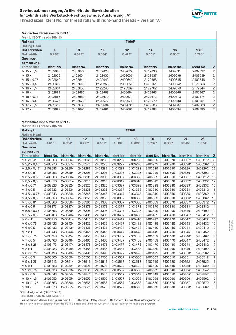
D.259www.lmt-tools.com
Gew
inde
rolle
n Th
read
Rol
ling
2403263 2403264 2403265 2403266 2403267 2403268 2403269 2403270 2403271 2403272 33 2403273 2403274 2403275 2403276 2403277 2403278 2403279 2403280 2403281 2403282 30 2403283 2403284 2403285 2403286 2403287 2403288 2403289 2403290 2403291 2403292 25 2403293 2403294 2403295 2403296 2403297 2403298 2403299 2403300 2403301 2403302 21 2403303 2403304 2403305 2403306 2403307 2403308 2403309 2403310 2403311 2403312 18 2403313 2403314 2403315 2403316 2403317 2403318 2403319 2403320 2403321 2403322 17 2403323 2403324 2403325 2403326 2403327 2403328 2403329 2403330 2403331 2403332 16 2403333 2403334 2403335 2403336 2403337 2403338 2403339 2403340 2403341 2403342 15 2403343 2403344 2403345 2403346 2403347 2403348 2403349 2403350 2403351 2403352 14 2403353 2403354 2403355 2403356 2403357 2403358 2403359 2403360 2403361 2403362 13 2403363 2403364 2403365 2403366 2403367 2403368 2403369 2403370 2403371 2403372 12 2403373 2403374 2403375 2403376 2403377 2403378 2403379 2403380 2403381 2403382 11 2403393 2403394 2403395 2403396 2403397 2403398 2403399 2403400 2403401 2403402 11 2403403 2403404 2403405 2403406 2403407 2403408 2403409 2403410 2403411 2403412 10 2403413 2403414 2403415 2403416 2403417 2403418 2403419 2403420 2403421 2403422 10 2403423 2403424 2403425 2403426 2403427 2403428 2403429 2403430 2403431 2403432 10 2403433 2403434 2403435 2403436 2403437 2403438 2403439 2403440 2403441 2403442 9 2403443 2403444 2403445 2403446 2403447 2403448 2403449 2403450 2403451 2403452 8 2403453 2403454 2403455 2403456 2403457 2403458 2403459 2403460 2403461 2403462 8 2403463 2403464 2403465 2403466 2403467 2403468 2403469 2403470 2403471 2403472 8 2403473 2403474 2403475 2403476 2403477 2403478 2403479 2403480 2403481 2403482 7 2403483 2403484 2403485 2403486 2403487 2403488 2403489 2403490 2403491 2403492 7 2403493 2403494 2403495 2403496 2403497 2403498 2403499 2403500 2403501 2403502 7 2403503 2403504 2403505 2403506 2403507 2403508 2403509 2403510 2403511 2403512 7 2403513 2403514 2403515 2403516 2403517 2403518 2403519 2403520 2403521 2403522 6 2403523 2403524 2403525 2403526 2403527 2403528 2403529 2403530 2403531 2403532 6 2403533 2403534 2403535 2403536 2403537 2403538 2403539 2403540 2403541 2403542 6 2403543 2403544 2403545 2403546 2403547 2403548 2403549 2403550 2403551 2403552 6 2403553 2403554 2403555 2403556 2403557 2403558 2403559 2403560 2403561 2403562 6 2403563 2403564 2403565 2403566 2403567 2403568 2403569 2403570 2403571 2403572 6 2403573 2403574 2403575 2403576 2403577 2403578 2403579 2403580 2403581 2403582 5
2402626 2402627 2402628 2402629 2402630 2402631 2402632 2 2402633 2402634 2402635 2402636 2402637 2402638 2402639 2 2402640 2402641 2402642 2402643 2172668 2402645 2402646 2 2402647 2402648 2172255 2402650 2402651 2402652 2172256 2 2402654 2402655 2172243 2170362 2172762 2402659 2172244 2 2402661 2402662 2402663 2402664 2402665 2402666 2402667 2 2402668 2402669 2402670 2402671 2402672 2402673 2402674 2 2402675 2402676 2402677 2402678 2402679 2402680 2402681 2 2402682 2402683 2402684 2402685 2402686 2402687 2402688 2 2402689 2402690 2402691 2402692 2402693 2402694 2402695 2
M 2 x 0,4* M 2,2 x 0,45* M 2,5 x 0,45* M 3 x 0,5* M 3,5 x 0,6* M 3,5 x 0,5 M 4 x 0,7* M 4 x 0,5 M 4,5 x 0,75* M 4,5 x 0,5 M 5 x 0,8* M 5 x 0,5 M 5,5 x 0,75 M 5,5 x 0,5 M 6 x 1* M 6 x 0,75 M 6 x 0,5 M 7 x 1 M 7 x 0,75 M 7 x 0,5 M 8 x 1,25* M 8 x 1 M 8 x 0,75 M 8 x 0,5 M 9 x 1,25 M 9 x 1 M 9 x 0,75 M 9 x 0,5 M 10 x 1,5* M 10 x 1,25 M 10 x 1
Gewindeabmessungen, Artikel-Nr. der Gewinderollen für zylindrische Werkstück-Rechtsgewinde, Ausführung „A“Thread sizes, Ident No. for thread rolls with right-hand threads – Version “A”
M 15 x 1,5M 15 x 1M 15 x 0,75M 15 x 0,5M 16 x 1,5M 16 x 1M 16 x 0,75M 16 x 0,5M 17 x 1,5M 17 x 1
Metrisches ISO-Gewinde DIN 13Metric ISO Threads DIN 13Rollkopf T160FRolling HeadRollenbreiten 6 8 10 12 14 16 18,5Roll width 0.236" 0.315" 0.394" 0.472" 0.551" 0.630" 0.728"Gewinde-abmessungThread size Ident No. Ident No. Ident No. Ident No. Ident No. Ident No. Ident No. Z
Metrisches ISO-Gewinde DIN 13Metric ISO Threads DIN 13Rollkopf T220FRolling HeadRollenbreiten 8 10 12 14 16 18 20 22 24 26Roll width 0.315" 0.394" 0.472" 0.551" 0.630" 0.709" 0.787" 0.866" 0.945" 1.024"Gewinde-abmessungThread size Ident No. Ident No. Ident No. Ident No. Ident No. Ident No. Ident No. Ident No. Ident No. Ident No. Z
* Standardgewinde (DIN 13 Teil 1) * Standard thread (to DIN 13 part 1)
Dies ist nur ein kleiner Auszug aus dem FETTE-Katalog „Rollsysteme“. Bitte fordern Sie das Gesamtprogramm an.This is only a small excerpt from the FETTE catalogue „Rolling systems“. Please ask for the standard program.
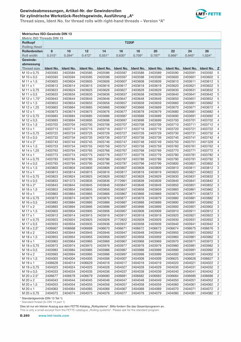
D.260 www.lmt-tools.com
M 10 x 0,75 M 10 x 0,5 M 11 x 1,5 M 11 x 1 M 11 x 0,75 M 11 x 0,5 M 12 x 1,75* M 12 x 1,5 M 12 x 1,25 M 12 x 1M 12 x 0,75M 12 x 0,5M 13 x 1,5M 13 x 1M 13 x 0,75M 13 x 0,5M 14 x 2*M 14 x 1,5M 14 x 1,25M 14 x 1M 14 x 0,75M 14 x 0,5M 15 x 1,5M 15 x 1M 15 x 0,75M 15 x 0,5M 16 x 2*M 16 x 1,5M 16 x 1M 16 x 0,75M 16 x 0,5M 17 x 2M 17 x 1,5M 17 x 1M 17 x 0,75M 17 x 0,5M 18 x 2,5*M 18 x 2M 18 x 1,5M 18 x 1M 18 x 0,75M 18 x 0,5M 19 x 2M 19 x 1,5M 19 x 1M 19 x 0,75M 19 x 0,5M 20 x 2,5*M 20 x 2M 20 x 1,5M 20 x 1M 20 x 0,75
Gewindeabmessungen, Artikel-Nr. der Gewinderollen für zylindrische Werkstück-Rechtsgewinde, Ausführung „A“Thread sizes, Ident No. for thread rolls with right-hand threads – Version “A”
2403583 2403584 2403585 2403586 2403587 2403588 2403589 2403590 2403591 2403592 5 2403593 2403594 2403595 2403596 2403597 2403598 2403599 2403600 2403601 2403602 5 2403603 2403604 2403605 2403606 2403607 2403608 2403609 2403610 2403611 2403612 5 2403613 2403614 2403615 2403616 2403617 2403618 2403619 2403620 2403621 2403622 5 2403623 2403624 2403625 2403626 2403627 2403628 2403629 2403630 2403631 2403632 5 2403633 2403634 2403635 2403636 2403637 2403638 2403639 2403640 2403641 2403642 5 2403643 2403644 2403645 2403646 2403647 2403648 2403649 2403650 2403651 2403652 5 2403653 2403654 2403655 2403656 2403657 2403658 2403659 2403660 2403661 2403662 5 2403663 2403664 2403665 2403666 2403667 2403668 2403669 2403670 2403671 2403672 4 2403673 2403674 2403675 2403676 2403677 2403678 2403679 2403680 2403681 2403682 4 2403683 2403684 2403685 2403686 2403687 2403688 2403689 2403690 2403691 2403692 4 2403693 2403694 2403695 2403696 2403697 2403698 2403699 2403700 2403701 2403702 4 2403703 2403704 2403705 2403706 2403707 2403708 2403709 2403710 2403711 2403712 4 2403713 2403714 2403715 2403716 2403717 2403718 2403719 2403720 2403721 2403722 4 2403723 2403724 2403725 2403726 2403727 2403728 2403729 2403730 2403731 2403732 4 2403733 2403734 2403735 2403736 2403737 2403738 2403739 2403740 2403741 2403742 4 2403743 2403744 2403745 2403746 2403747 2403748 2403749 2403750 2403751 2401329 4 2403753 2403754 2403755 2403756 2403757 2403758 2403759 2403760 2403761 2403762 4 2403763 2403764 2403765 2403766 2403767 2403768 2403769 2403770 2403771 2403772 4 2403773 2403774 2403775 2403776 2403777 2403778 2403779 2403780 2403781 2403782 4 2403783 2403784 2403785 2403786 2403787 2403788 2403789 2403790 2403791 2403792 3 2403793 2403794 2403795 2403796 2403797 2403798 2403799 2403800 2403801 2403802 3 2403803 2403804 2403805 2403806 2403807 2403808 2403809 2403810 2403811 2403812 3 2403813 2403814 2403815 2403816 2403817 2403818 2403819 2403820 2403821 2403822 3 2403823 2403824 2403825 2403826 2403827 2403828 2403829 2403830 2403831 2403832 3 2403833 2401373 2403835 2403836 2172661 2403838 2403839 2403840 2403841 2403842 3 2403843 2403844 2403845 2403846 2403847 2403848 2403849 2403850 2403851 2403852 3 2403853 2403854 2403855 2403856 2403857 2403858 2403859 2403860 2403861 2403862 3 2403863 2403864 2403865 2403866 2403867 2403868 2403869 2403870 2403871 2403872 3 2403873 2403874 2403875 2403876 2403877 2403878 2403879 2403880 2403881 2403882 3 2403883 2403884 2403885 2403886 2403887 2403888 2403889 2403890 2403891 2403892 3 2403893 2403894 2403895 2403896 2403897 2403898 2403899 2403900 2403901 2403902 3 2403903 2403904 2403905 2403906 2403907 2403908 2403909 2403910 2403911 2403912 3 2403913 2403914 2403915 2403916 2403917 2403918 2403919 2403920 2403921 2403922 3 2403923 2403924 2403925 2403926 2172822 2403928 2403929 2403930 2403931 2403932 3 2403933 2403934 2403935 2403936 2403937 2403938 2403939 2403940 2403941 2403942 3 2406667 2406668 2406669 2406670 2406671 2406672 2406673 2406674 2406675 2406676 3 2403943 2403944 2403945 2403946 2403947 2403948 2403949 2403950 2403951 2403952 3 2403953 2403954 2403955 2403956 2403957 2403958 2403959 2403960 2403961 2403962 3 2403963 2403964 2403965 2403966 2403967 2403968 2403969 2403970 2403971 2403972 3 2403973 2403974 2403975 2403976 2403977 2403978 2403979 2403980 2403981 2403982 3 2403983 2403984 2403985 2403986 2403987 2403988 2403989 2403990 2403991 2403992 3 2403993 2403994 2403995 2403996 2403997 2403998 2403999 2404000 2404001 2404002 3 2404003 2404004 2404005 2404006 2404007 2404008 2404009 2406625 2406626 2406627 3 2406628 2404014 2406629 2404016 2404017 2404018 2404019 2404020 2404021 2404022 2 2404023 2404024 2404025 2404026 2404027 2404028 2404029 2404030 2404031 2404032 2 2404033 2404034 2404035 2404036 2404037 2404038 2404039 2404040 2404041 2404042 2 2406677 2406678 2406679 2406680 2406681 2406682 2406683 2406684 2406685 2406686 2 2404043 2404044 2404045 2404046 2404047 2404048 2404049 2404050 2404051 2404052 2 2404053 2404054 2404055 2404056 2404057 2404058 2404059 2404060 2404061 2404062 2 2404063 2404064 2404065 2404066 2404067 2404068 2404069 2404070 2404071 2404072 2 2404073 2404074 2404075 2404076 2404077 2404078 2404079 2404080 2404081 2404082 2
Metrisches ISO-Gewinde DIN 13Metric ISO Threads DIN 13Rollkopf T220FRolling HeadRollenbreiten 8 10 12 14 16 18 20 22 24 26Roll width 0.315" 0.394" 0.472" 0.551" 0.630" 0.709" 0.787" 0.866" 0.945" 1.024"Gewinde-abmessungThread size Ident No. Ident No. Ident No. Ident No. Ident No. Ident No. Ident No. Ident No. Ident No. Ident No. Z
* Standardgewinde (DIN 13 Teil 1) * Standard thread (to DIN 13 part 1)
Dies ist nur ein kleiner Auszug aus dem FETTE-Katalog „Rollsysteme“. Bitte fordern Sie das Gesamtprogramm an.This is only a small excerpt from the FETTE catalogue „Rolling systems“. Please ask for the standard program.
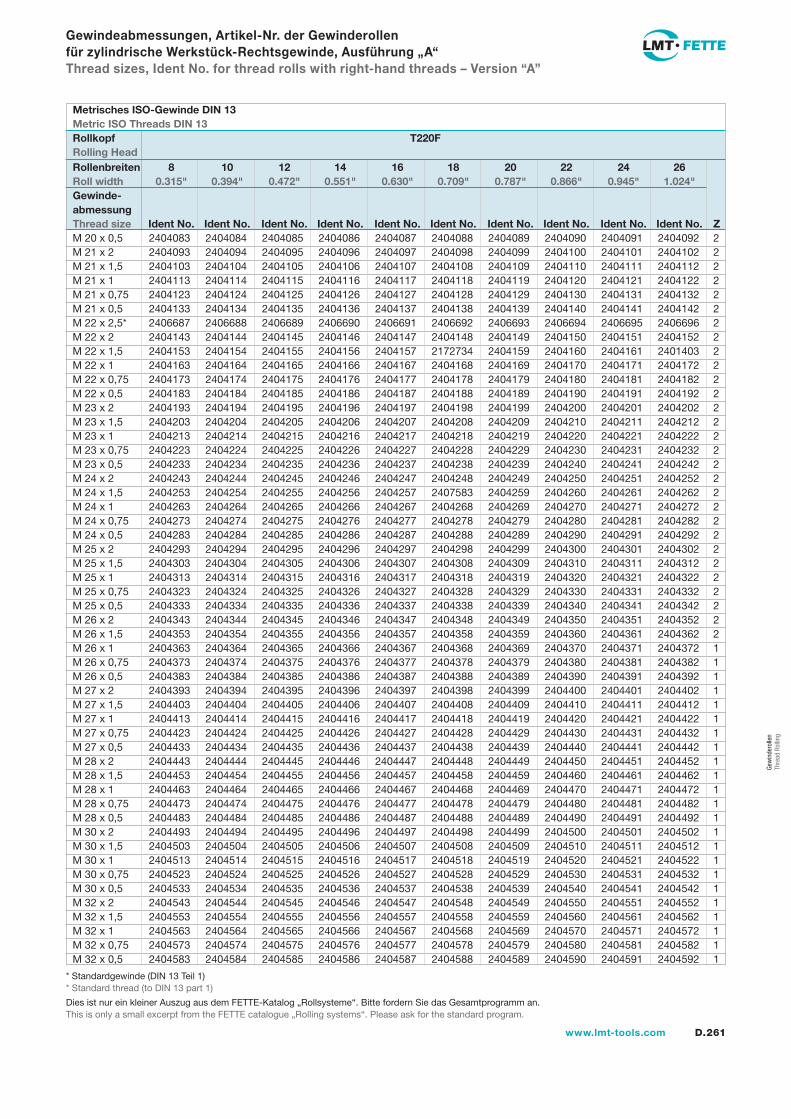
D.261www.lmt-tools.com
Gew
inde
rolle
n Th
read
Rol
ling
2404083 2404084 2404085 2404086 2404087 2404088 2404089 2404090 2404091 2404092 2 2404093 2404094 2404095 2404096 2404097 2404098 2404099 2404100 2404101 2404102 2 2404103 2404104 2404105 2404106 2404107 2404108 2404109 2404110 2404111 2404112 2 2404113 2404114 2404115 2404116 2404117 2404118 2404119 2404120 2404121 2404122 2 2404123 2404124 2404125 2404126 2404127 2404128 2404129 2404130 2404131 2404132 2 2404133 2404134 2404135 2404136 2404137 2404138 2404139 2404140 2404141 2404142 2 2406687 2406688 2406689 2406690 2406691 2406692 2406693 2406694 2406695 2406696 2 2404143 2404144 2404145 2404146 2404147 2404148 2404149 2404150 2404151 2404152 2 2404153 2404154 2404155 2404156 2404157 2172734 2404159 2404160 2404161 2401403 2 2404163 2404164 2404165 2404166 2404167 2404168 2404169 2404170 2404171 2404172 2 2404173 2404174 2404175 2404176 2404177 2404178 2404179 2404180 2404181 2404182 2 2404183 2404184 2404185 2404186 2404187 2404188 2404189 2404190 2404191 2404192 2 2404193 2404194 2404195 2404196 2404197 2404198 2404199 2404200 2404201 2404202 2 2404203 2404204 2404205 2404206 2404207 2404208 2404209 2404210 2404211 2404212 2 2404213 2404214 2404215 2404216 2404217 2404218 2404219 2404220 2404221 2404222 2 2404223 2404224 2404225 2404226 2404227 2404228 2404229 2404230 2404231 2404232 2 2404233 2404234 2404235 2404236 2404237 2404238 2404239 2404240 2404241 2404242 2 2404243 2404244 2404245 2404246 2404247 2404248 2404249 2404250 2404251 2404252 2 2404253 2404254 2404255 2404256 2404257 2407583 2404259 2404260 2404261 2404262 2 2404263 2404264 2404265 2404266 2404267 2404268 2404269 2404270 2404271 2404272 2 2404273 2404274 2404275 2404276 2404277 2404278 2404279 2404280 2404281 2404282 2 2404283 2404284 2404285 2404286 2404287 2404288 2404289 2404290 2404291 2404292 2 2404293 2404294 2404295 2404296 2404297 2404298 2404299 2404300 2404301 2404302 2 2404303 2404304 2404305 2404306 2404307 2404308 2404309 2404310 2404311 2404312 2 2404313 2404314 2404315 2404316 2404317 2404318 2404319 2404320 2404321 2404322 2 2404323 2404324 2404325 2404326 2404327 2404328 2404329 2404330 2404331 2404332 2 2404333 2404334 2404335 2404336 2404337 2404338 2404339 2404340 2404341 2404342 2 2404343 2404344 2404345 2404346 2404347 2404348 2404349 2404350 2404351 2404352 2 2404353 2404354 2404355 2404356 2404357 2404358 2404359 2404360 2404361 2404362 2 2404363 2404364 2404365 2404366 2404367 2404368 2404369 2404370 2404371 2404372 1 2404373 2404374 2404375 2404376 2404377 2404378 2404379 2404380 2404381 2404382 1 2404383 2404384 2404385 2404386 2404387 2404388 2404389 2404390 2404391 2404392 1 2404393 2404394 2404395 2404396 2404397 2404398 2404399 2404400 2404401 2404402 1 2404403 2404404 2404405 2404406 2404407 2404408 2404409 2404410 2404411 2404412 1 2404413 2404414 2404415 2404416 2404417 2404418 2404419 2404420 2404421 2404422 1 2404423 2404424 2404425 2404426 2404427 2404428 2404429 2404430 2404431 2404432 1 2404433 2404434 2404435 2404436 2404437 2404438 2404439 2404440 2404441 2404442 1 2404443 2404444 2404445 2404446 2404447 2404448 2404449 2404450 2404451 2404452 1 2404453 2404454 2404455 2404456 2404457 2404458 2404459 2404460 2404461 2404462 1 2404463 2404464 2404465 2404466 2404467 2404468 2404469 2404470 2404471 2404472 1 2404473 2404474 2404475 2404476 2404477 2404478 2404479 2404480 2404481 2404482 1 2404483 2404484 2404485 2404486 2404487 2404488 2404489 2404490 2404491 2404492 1 2404493 2404494 2404495 2404496 2404497 2404498 2404499 2404500 2404501 2404502 1 2404503 2404504 2404505 2404506 2404507 2404508 2404509 2404510 2404511 2404512 1 2404513 2404514 2404515 2404516 2404517 2404518 2404519 2404520 2404521 2404522 1 2404523 2404524 2404525 2404526 2404527 2404528 2404529 2404530 2404531 2404532 1 2404533 2404534 2404535 2404536 2404537 2404538 2404539 2404540 2404541 2404542 1 2404543 2404544 2404545 2404546 2404547 2404548 2404549 2404550 2404551 2404552 1 2404553 2404554 2404555 2404556 2404557 2404558 2404559 2404560 2404561 2404562 1 2404563 2404564 2404565 2404566 2404567 2404568 2404569 2404570 2404571 2404572 1 2404573 2404574 2404575 2404576 2404577 2404578 2404579 2404580 2404581 2404582 1 2404583 2404584 2404585 2404586 2404587 2404588 2404589 2404590 2404591 2404592 1
Gewindeabmessungen, Artikel-Nr. der Gewinderollen für zylindrische Werkstück-Rechtsgewinde, Ausführung „A“Thread sizes, Ident No. for thread rolls with right-hand threads – Version “A”
M 20 x 0,5M 21 x 2M 21 x 1,5M 21 x 1M 21 x 0,75M 21 x 0,5M 22 x 2,5*M 22 x 2M 22 x 1,5M 22 x 1M 22 x 0,75M 22 x 0,5M 23 x 2M 23 x 1,5M 23 x 1M 23 x 0,75M 23 x 0,5M 24 x 2M 24 x 1,5M 24 x 1M 24 x 0,75M 24 x 0,5M 25 x 2M 25 x 1,5M 25 x 1M 25 x 0,75M 25 x 0,5M 26 x 2M 26 x 1,5M 26 x 1M 26 x 0,75M 26 x 0,5M 27 x 2M 27 x 1,5M 27 x 1M 27 x 0,75M 27 x 0,5M 28 x 2M 28 x 1,5M 28 x 1M 28 x 0,75M 28 x 0,5M 30 x 2M 30 x 1,5M 30 x 1M 30 x 0,75M 30 x 0,5M 32 x 2M 32 x 1,5M 32 x 1M 32 x 0,75M 32 x 0,5
Metrisches ISO-Gewinde DIN 13Metric ISO Threads DIN 13Rollkopf T220FRolling HeadRollenbreiten 8 10 12 14 16 18 20 22 24 26Roll width 0.315" 0.394" 0.472" 0.551" 0.630" 0.709" 0.787" 0.866" 0.945" 1.024"Gewinde-abmessungThread size Ident No. Ident No. Ident No. Ident No. Ident No. Ident No. Ident No. Ident No. Ident No. Ident No. Z
* Standardgewinde (DIN 13 Teil 1) * Standard thread (to DIN 13 part 1)
Dies ist nur ein kleiner Auszug aus dem FETTE-Katalog „Rollsysteme“. Bitte fordern Sie das Gesamtprogramm an.This is only a small excerpt from the FETTE catalogue „Rolling systems“. Please ask for the standard program.
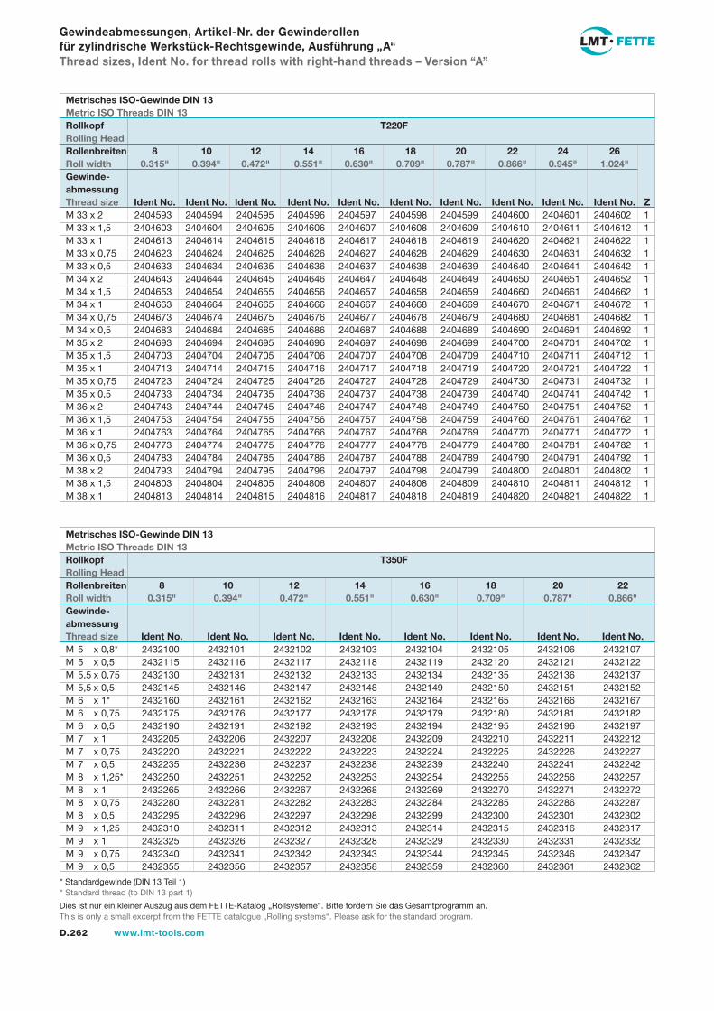
D.262 www.lmt-tools.com
2404593 2404594 2404595 2404596 2404597 2404598 2404599 2404600 2404601 2404602 1 2404603 2404604 2404605 2404606 2404607 2404608 2404609 2404610 2404611 2404612 1 2404613 2404614 2404615 2404616 2404617 2404618 2404619 2404620 2404621 2404622 1 2404623 2404624 2404625 2404626 2404627 2404628 2404629 2404630 2404631 2404632 1 2404633 2404634 2404635 2404636 2404637 2404638 2404639 2404640 2404641 2404642 1 2404643 2404644 2404645 2404646 2404647 2404648 2404649 2404650 2404651 2404652 1 2404653 2404654 2404655 2404656 2404657 2404658 2404659 2404660 2404661 2404662 1 2404663 2404664 2404665 2404666 2404667 2404668 2404669 2404670 2404671 2404672 1 2404673 2404674 2404675 2404676 2404677 2404678 2404679 2404680 2404681 2404682 1 2404683 2404684 2404685 2404686 2404687 2404688 2404689 2404690 2404691 2404692 1 2404693 2404694 2404695 2404696 2404697 2404698 2404699 2404700 2404701 2404702 1 2404703 2404704 2404705 2404706 2404707 2404708 2404709 2404710 2404711 2404712 1 2404713 2404714 2404715 2404716 2404717 2404718 2404719 2404720 2404721 2404722 1 2404723 2404724 2404725 2404726 2404727 2404728 2404729 2404730 2404731 2404732 1 2404733 2404734 2404735 2404736 2404737 2404738 2404739 2404740 2404741 2404742 1 2404743 2404744 2404745 2404746 2404747 2404748 2404749 2404750 2404751 2404752 1 2404753 2404754 2404755 2404756 2404757 2404758 2404759 2404760 2404761 2404762 1 2404763 2404764 2404765 2404766 2404767 2404768 2404769 2404770 2404771 2404772 1 2404773 2404774 2404775 2404776 2404777 2404778 2404779 2404780 2404781 2404782 1 2404783 2404784 2404785 2404786 2404787 2404788 2404789 2404790 2404791 2404792 1 2404793 2404794 2404795 2404796 2404797 2404798 2404799 2404800 2404801 2404802 1 2404803 2404804 2404805 2404806 2404807 2404808 2404809 2404810 2404811 2404812 1 2404813 2404814 2404815 2404816 2404817 2404818 2404819 2404820 2404821 2404822 1
Gewindeabmessungen, Artikel-Nr. der Gewinderollen für zylindrische Werkstück-Rechtsgewinde, Ausführung „A“Thread sizes, Ident No. for thread rolls with right-hand threads – Version “A”
M 33 x 2M 33 x 1,5M 33 x 1M 33 x 0,75M 33 x 0,5M 34 x 2M 34 x 1,5M 34 x 1M 34 x 0,75M 34 x 0,5M 35 x 2M 35 x 1,5M 35 x 1M 35 x 0,75M 35 x 0,5M 36 x 2M 36 x 1,5M 36 x 1M 36 x 0,75M 36 x 0,5M 38 x 2M 38 x 1,5M 38 x 1
Metrisches ISO-Gewinde DIN 13Metric ISO Threads DIN 13Rollkopf T220FRolling HeadRollenbreiten 8 10 12 14 16 18 20 22 24 26Roll width 0.315" 0.394" 0.472" 0.551" 0.630" 0.709" 0.787" 0.866" 0.945" 1.024"Gewinde-abmessungThread size Ident No. Ident No. Ident No. Ident No. Ident No. Ident No. Ident No. Ident No. Ident No. Ident No. Z
* Standardgewinde (DIN 13 Teil 1) * Standard thread (to DIN 13 part 1)
2432100 2432101 2432102 2432103 2432104 2432105 2432106 2432107 2432115 2432116 2432117 2432118 2432119 2432120 2432121 2432122 2432130 2432131 2432132 2432133 2432134 2432135 2432136 2432137 2432145 2432146 2432147 2432148 2432149 2432150 2432151 2432152 2432160 2432161 2432162 2432163 2432164 2432165 2432166 2432167 2432175 2432176 2432177 2432178 2432179 2432180 2432181 2432182 2432190 2432191 2432192 2432193 2432194 2432195 2432196 2432197 2432205 2432206 2432207 2432208 2432209 2432210 2432211 2432212 2432220 2432221 2432222 2432223 2432224 2432225 2432226 2432227 2432235 2432236 2432237 2432238 2432239 2432240 2432241 2432242 2432250 2432251 2432252 2432253 2432254 2432255 2432256 2432257 2432265 2432266 2432267 2432268 2432269 2432270 2432271 2432272 2432280 2432281 2432282 2432283 2432284 2432285 2432286 2432287 2432295 2432296 2432297 2432298 2432299 2432300 2432301 2432302 2432310 2432311 2432312 2432313 2432314 2432315 2432316 2432317 2432325 2432326 2432327 2432328 2432329 2432330 2432331 2432332 2432340 2432341 2432342 2432343 2432344 2432345 2432346 2432347 2432355 2432356 2432357 2432358 2432359 2432360 2432361 2432362
M 5 x 0,8*M 5 x 0,5M 5,5 x 0,75M 5,5 x 0,5M 6 x 1*M 6 x 0,75M 6 x 0,5M 7 x 1M 7 x 0,75M 7 x 0,5M 8 x 1,25*M 8 x 1M 8 x 0,75M 8 x 0,5M 9 x 1,25M 9 x 1M 9 x 0,75M 9 x 0,5
Metrisches ISO-Gewinde DIN 13Metric ISO Threads DIN 13Rollkopf T350FRolling HeadRollenbreiten 8 10 12 14 16 18 20 22Roll width 0.315" 0.394" 0.472" 0.551" 0.630" 0.709" 0.787" 0.866"Gewinde-abmessungThread size Ident No. Ident No. Ident No. Ident No. Ident No. Ident No. Ident No. Ident No.
Dies ist nur ein kleiner Auszug aus dem FETTE-Katalog „Rollsysteme“. Bitte fordern Sie das Gesamtprogramm an.This is only a small excerpt from the FETTE catalogue „Rolling systems“. Please ask for the standard program.
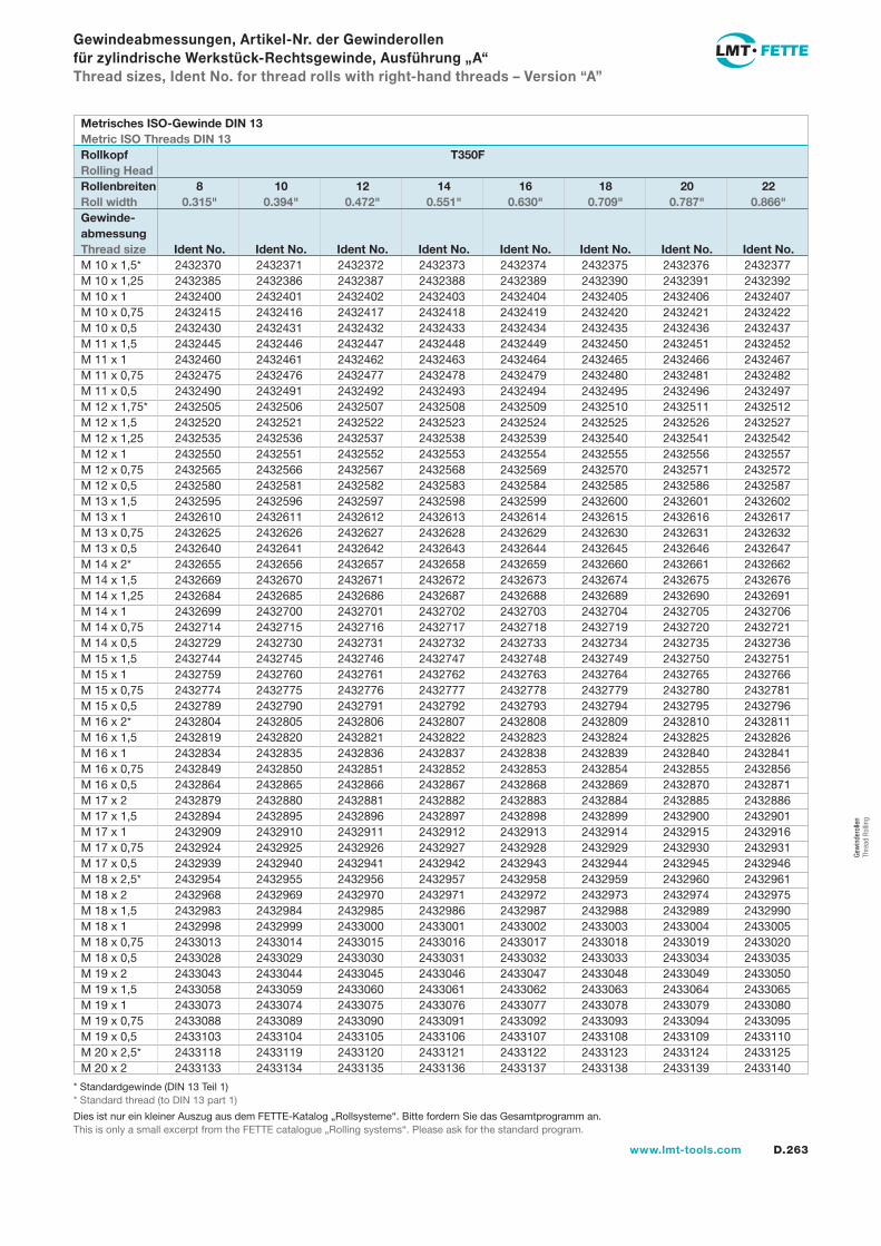
D.263www.lmt-tools.com
Gew
inde
rolle
n Th
read
Rol
ling
Gewindeabmessungen, Artikel-Nr. der Gewinderollen für zylindrische Werkstück-Rechtsgewinde, Ausführung „A“Thread sizes, Ident No. for thread rolls with right-hand threads – Version “A”
2432370 2432371 2432372 2432373 2432374 2432375 2432376 2432377 2432385 2432386 2432387 2432388 2432389 2432390 2432391 2432392 2432400 2432401 2432402 2432403 2432404 2432405 2432406 2432407 2432415 2432416 2432417 2432418 2432419 2432420 2432421 2432422 2432430 2432431 2432432 2432433 2432434 2432435 2432436 2432437 2432445 2432446 2432447 2432448 2432449 2432450 2432451 2432452 2432460 2432461 2432462 2432463 2432464 2432465 2432466 2432467 2432475 2432476 2432477 2432478 2432479 2432480 2432481 2432482 2432490 2432491 2432492 2432493 2432494 2432495 2432496 2432497 2432505 2432506 2432507 2432508 2432509 2432510 2432511 2432512 2432520 2432521 2432522 2432523 2432524 2432525 2432526 2432527 2432535 2432536 2432537 2432538 2432539 2432540 2432541 2432542 2432550 2432551 2432552 2432553 2432554 2432555 2432556 2432557 2432565 2432566 2432567 2432568 2432569 2432570 2432571 2432572 2432580 2432581 2432582 2432583 2432584 2432585 2432586 2432587 2432595 2432596 2432597 2432598 2432599 2432600 2432601 2432602 2432610 2432611 2432612 2432613 2432614 2432615 2432616 2432617 2432625 2432626 2432627 2432628 2432629 2432630 2432631 2432632 2432640 2432641 2432642 2432643 2432644 2432645 2432646 2432647 2432655 2432656 2432657 2432658 2432659 2432660 2432661 2432662 2432669 2432670 2432671 2432672 2432673 2432674 2432675 2432676 2432684 2432685 2432686 2432687 2432688 2432689 2432690 2432691 2432699 2432700 2432701 2432702 2432703 2432704 2432705 2432706 2432714 2432715 2432716 2432717 2432718 2432719 2432720 2432721 2432729 2432730 2432731 2432732 2432733 2432734 2432735 2432736 2432744 2432745 2432746 2432747 2432748 2432749 2432750 2432751 2432759 2432760 2432761 2432762 2432763 2432764 2432765 2432766 2432774 2432775 2432776 2432777 2432778 2432779 2432780 2432781 2432789 2432790 2432791 2432792 2432793 2432794 2432795 2432796 2432804 2432805 2432806 2432807 2432808 2432809 2432810 2432811 2432819 2432820 2432821 2432822 2432823 2432824 2432825 2432826 2432834 2432835 2432836 2432837 2432838 2432839 2432840 2432841 2432849 2432850 2432851 2432852 2432853 2432854 2432855 2432856 2432864 2432865 2432866 2432867 2432868 2432869 2432870 2432871 2432879 2432880 2432881 2432882 2432883 2432884 2432885 2432886 2432894 2432895 2432896 2432897 2432898 2432899 2432900 2432901 2432909 2432910 2432911 2432912 2432913 2432914 2432915 2432916 2432924 2432925 2432926 2432927 2432928 2432929 2432930 2432931 2432939 2432940 2432941 2432942 2432943 2432944 2432945 2432946 2432954 2432955 2432956 2432957 2432958 2432959 2432960 2432961 2432968 2432969 2432970 2432971 2432972 2432973 2432974 2432975 2432983 2432984 2432985 2432986 2432987 2432988 2432989 2432990 2432998 2432999 2433000 2433001 2433002 2433003 2433004 2433005 2433013 2433014 2433015 2433016 2433017 2433018 2433019 2433020 2433028 2433029 2433030 2433031 2433032 2433033 2433034 2433035 2433043 2433044 2433045 2433046 2433047 2433048 2433049 2433050 2433058 2433059 2433060 2433061 2433062 2433063 2433064 2433065 2433073 2433074 2433075 2433076 2433077 2433078 2433079 2433080 2433088 2433089 2433090 2433091 2433092 2433093 2433094 2433095 2433103 2433104 2433105 2433106 2433107 2433108 2433109 2433110 2433118 2433119 2433120 2433121 2433122 2433123 2433124 2433125 2433133 2433134 2433135 2433136 2433137 2433138 2433139 2433140
M 10 x 1,5*M 10 x 1,25M 10 x 1M 10 x 0,75M 10 x 0,5M 11 x 1,5M 11 x 1M 11 x 0,75M 11 x 0,5M 12 x 1,75*M 12 x 1,5M 12 x 1,25M 12 x 1M 12 x 0,75M 12 x 0,5M 13 x 1,5M 13 x 1M 13 x 0,75M 13 x 0,5M 14 x 2*M 14 x 1,5M 14 x 1,25M 14 x 1M 14 x 0,75M 14 x 0,5M 15 x 1,5M 15 x 1M 15 x 0,75M 15 x 0,5M 16 x 2*M 16 x 1,5M 16 x 1M 16 x 0,75M 16 x 0,5M 17 x 2M 17 x 1,5M 17 x 1M 17 x 0,75M 17 x 0,5M 18 x 2,5*M 18 x 2M 18 x 1,5M 18 x 1M 18 x 0,75M 18 x 0,5M 19 x 2M 19 x 1,5M 19 x 1M 19 x 0,75M 19 x 0,5M 20 x 2,5*M 20 x 2
Metrisches ISO-Gewinde DIN 13Metric ISO Threads DIN 13Rollkopf T350FRolling HeadRollenbreiten 8 10 12 14 16 18 20 22Roll width 0.315" 0.394" 0.472" 0.551" 0.630" 0.709" 0.787" 0.866"Gewinde-abmessungThread size Ident No. Ident No. Ident No. Ident No. Ident No. Ident No. Ident No. Ident No.
* Standardgewinde (DIN 13 Teil 1) * Standard thread (to DIN 13 part 1)
Dies ist nur ein kleiner Auszug aus dem FETTE-Katalog „Rollsysteme“. Bitte fordern Sie das Gesamtprogramm an.This is only a small excerpt from the FETTE catalogue „Rolling systems“. Please ask for the standard program.
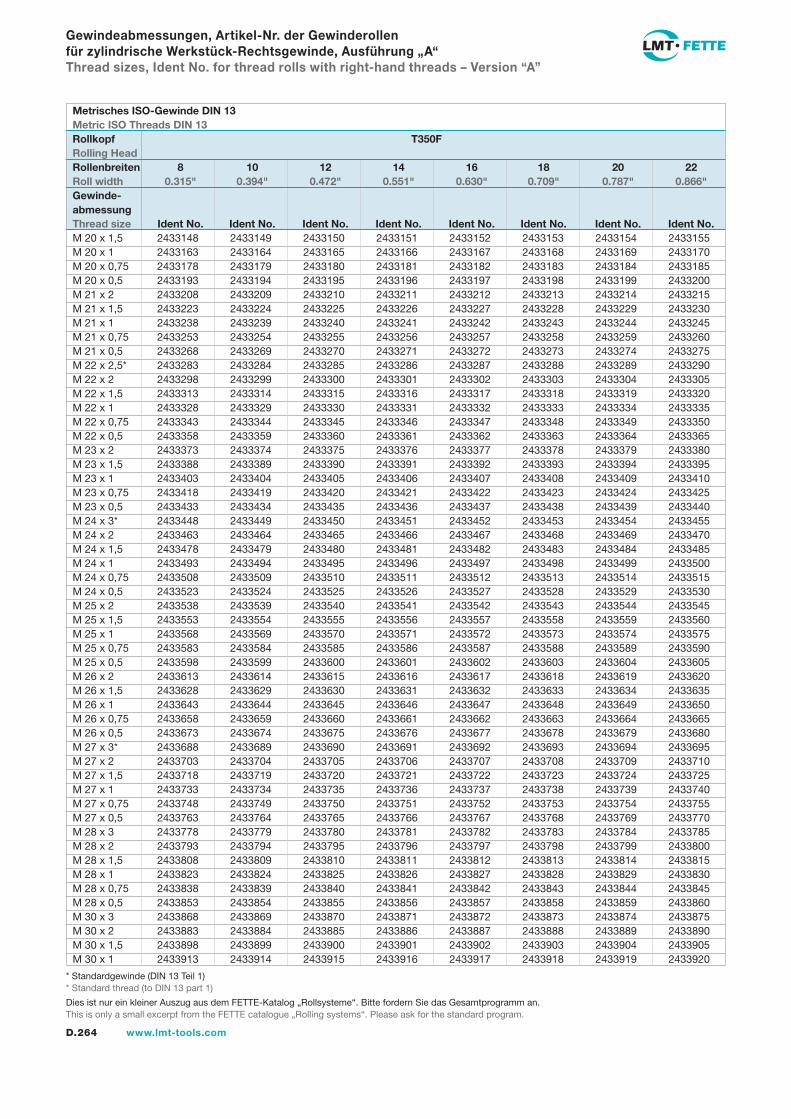
D.264 www.lmt-tools.com
Gewindeabmessungen, Artikel-Nr. der Gewinderollen für zylindrische Werkstück-Rechtsgewinde, Ausführung „A“Thread sizes, Ident No. for thread rolls with right-hand threads – Version “A”
2433148 2433149 2433150 2433151 2433152 2433153 2433154 2433155 2433163 2433164 2433165 2433166 2433167 2433168 2433169 2433170 2433178 2433179 2433180 2433181 2433182 2433183 2433184 2433185 2433193 2433194 2433195 2433196 2433197 2433198 2433199 2433200 2433208 2433209 2433210 2433211 2433212 2433213 2433214 2433215 2433223 2433224 2433225 2433226 2433227 2433228 2433229 2433230 2433238 2433239 2433240 2433241 2433242 2433243 2433244 2433245 2433253 2433254 2433255 2433256 2433257 2433258 2433259 2433260 2433268 2433269 2433270 2433271 2433272 2433273 2433274 2433275 2433283 2433284 2433285 2433286 2433287 2433288 2433289 2433290 2433298 2433299 2433300 2433301 2433302 2433303 2433304 2433305 2433313 2433314 2433315 2433316 2433317 2433318 2433319 2433320 2433328 2433329 2433330 2433331 2433332 2433333 2433334 2433335 2433343 2433344 2433345 2433346 2433347 2433348 2433349 2433350 2433358 2433359 2433360 2433361 2433362 2433363 2433364 2433365 2433373 2433374 2433375 2433376 2433377 2433378 2433379 2433380 2433388 2433389 2433390 2433391 2433392 2433393 2433394 2433395 2433403 2433404 2433405 2433406 2433407 2433408 2433409 2433410 2433418 2433419 2433420 2433421 2433422 2433423 2433424 2433425 2433433 2433434 2433435 2433436 2433437 2433438 2433439 2433440 2433448 2433449 2433450 2433451 2433452 2433453 2433454 2433455 2433463 2433464 2433465 2433466 2433467 2433468 2433469 2433470 2433478 2433479 2433480 2433481 2433482 2433483 2433484 2433485 2433493 2433494 2433495 2433496 2433497 2433498 2433499 2433500 2433508 2433509 2433510 2433511 2433512 2433513 2433514 2433515 2433523 2433524 2433525 2433526 2433527 2433528 2433529 2433530 2433538 2433539 2433540 2433541 2433542 2433543 2433544 2433545 2433553 2433554 2433555 2433556 2433557 2433558 2433559 2433560 2433568 2433569 2433570 2433571 2433572 2433573 2433574 2433575 2433583 2433584 2433585 2433586 2433587 2433588 2433589 2433590 2433598 2433599 2433600 2433601 2433602 2433603 2433604 2433605 2433613 2433614 2433615 2433616 2433617 2433618 2433619 2433620 2433628 2433629 2433630 2433631 2433632 2433633 2433634 2433635 2433643 2433644 2433645 2433646 2433647 2433648 2433649 2433650 2433658 2433659 2433660 2433661 2433662 2433663 2433664 2433665 2433673 2433674 2433675 2433676 2433677 2433678 2433679 2433680 2433688 2433689 2433690 2433691 2433692 2433693 2433694 2433695 2433703 2433704 2433705 2433706 2433707 2433708 2433709 2433710 2433718 2433719 2433720 2433721 2433722 2433723 2433724 2433725 2433733 2433734 2433735 2433736 2433737 2433738 2433739 2433740 2433748 2433749 2433750 2433751 2433752 2433753 2433754 2433755 2433763 2433764 2433765 2433766 2433767 2433768 2433769 2433770 2433778 2433779 2433780 2433781 2433782 2433783 2433784 2433785 2433793 2433794 2433795 2433796 2433797 2433798 2433799 2433800 2433808 2433809 2433810 2433811 2433812 2433813 2433814 2433815 2433823 2433824 2433825 2433826 2433827 2433828 2433829 2433830 2433838 2433839 2433840 2433841 2433842 2433843 2433844 2433845 2433853 2433854 2433855 2433856 2433857 2433858 2433859 2433860 2433868 2433869 2433870 2433871 2433872 2433873 2433874 2433875 2433883 2433884 2433885 2433886 2433887 2433888 2433889 2433890 2433898 2433899 2433900 2433901 2433902 2433903 2433904 2433905 2433913 2433914 2433915 2433916 2433917 2433918 2433919 2433920
M 20 x 1,5M 20 x 1M 20 x 0,75M 20 x 0,5M 21 x 2M 21 x 1,5M 21 x 1M 21 x 0,75M 21 x 0,5M 22 x 2,5*M 22 x 2M 22 x 1,5M 22 x 1M 22 x 0,75M 22 x 0,5M 23 x 2M 23 x 1,5M 23 x 1M 23 x 0,75M 23 x 0,5M 24 x 3*M 24 x 2M 24 x 1,5M 24 x 1M 24 x 0,75M 24 x 0,5M 25 x 2M 25 x 1,5M 25 x 1M 25 x 0,75M 25 x 0,5M 26 x 2M 26 x 1,5M 26 x 1M 26 x 0,75M 26 x 0,5M 27 x 3*M 27 x 2M 27 x 1,5M 27 x 1M 27 x 0,75M 27 x 0,5M 28 x 3M 28 x 2M 28 x 1,5M 28 x 1M 28 x 0,75M 28 x 0,5M 30 x 3M 30 x 2M 30 x 1,5M 30 x 1
Metrisches ISO-Gewinde DIN 13Metric ISO Threads DIN 13Rollkopf T350FRolling HeadRollenbreiten 8 10 12 14 16 18 20 22Roll width 0.315" 0.394" 0.472" 0.551" 0.630" 0.709" 0.787" 0.866"Gewinde-abmessungThread size Ident No. Ident No. Ident No. Ident No. Ident No. Ident No. Ident No. Ident No.
* Standardgewinde (DIN 13 Teil 1) * Standard thread (to DIN 13 part 1)
Dies ist nur ein kleiner Auszug aus dem FETTE-Katalog „Rollsysteme“. Bitte fordern Sie das Gesamtprogramm an.This is only a small excerpt from the FETTE catalogue „Rolling systems“. Please ask for the standard program.
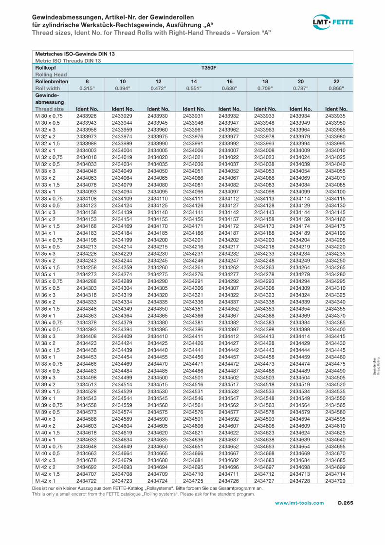
D.265www.lmt-tools.com
Gew
inde
rolle
n Th
read
Rol
ling
Gewindeabmessungen, Artikel-Nr. der Gewinderollen für zylindrische Werkstück-Rechtsgewinde, Ausführung „A“Thread sizes, Ident No. for Thread Rolls with Right-Hand Threads – Version “A”
2433928 2433929 2433930 2433931 2433932 2433933 2433934 2433935 2433943 2433944 2433945 2433946 2433947 2433948 2433949 2433950 2433958 2433959 2433960 2433961 2433962 2433963 2433964 2433965 2433973 2433974 2433975 2433976 2433977 2433978 2433979 2433980 2433988 2433989 2433990 2433991 2433992 2433993 2433994 2433995 2434003 2434004 2434005 2434006 2434007 2434008 2434009 2434010 2434018 2434019 2434020 2434021 2434022 2434023 2434024 2434025 2434033 2434034 2434035 2434036 2434037 2434038 2434039 2434040 2434048 2434049 2434050 2434051 2434052 2434053 2434054 2434055 2434063 2434064 2434065 2434066 2434067 2434068 2434069 2434070 2434078 2434079 2434080 2434081 2434082 2434083 2434084 2434085 2434093 2434094 2434095 2434096 2434097 2434098 2434099 2434100 2434108 2434109 2434110 2434111 2434112 2434113 2434114 2434115 2434123 2434124 2434125 2434126 2434127 2434128 2434129 2434130 2434138 2434139 2434140 2434141 2434142 2434143 2434144 2434145 2434153 2434154 2434155 2434156 2434157 2434158 2434159 2434160 2434168 2434169 2434170 2434171 2434172 2434173 2434174 2434175 2434183 2434184 2434185 2434186 2434187 2434188 2434189 2434190 2434198 2434199 2434200 2434201 2434202 2434203 2434204 2434205 2434213 2434214 2434215 2434216 2434217 2434218 2434219 2434220 2434228 2434229 2434230 2434231 2434232 2434233 2434234 2434235 2434243 2434244 2434245 2434246 2434247 2434248 2434249 2434250 2434258 2434259 2434260 2434261 2434262 2434263 2434264 2434265 2434273 2434274 2434275 2434276 2434277 2434278 2434279 2434280 2434288 2434289 2434290 2434291 2434292 2434293 2434294 2434295 2434303 2434304 2434305 2434306 2434307 2434308 2434309 2434310 2434318 2434319 2434320 2434321 2434322 2434323 2434324 2434325 2434333 2434334 2434335 2434336 2434337 2434338 2434339 2434340 2434348 2434349 2434350 2434351 2434352 2434353 2434354 2434355 2434363 2434364 2434365 2434366 2434367 2434368 2434369 2434370 2434378 2434379 2434380 2434381 2434382 2434383 2434384 2434385 2434393 2434394 2434395 2434396 2434397 2434398 2434399 2434400 2434408 2434409 2434410 2434411 2434412 2434413 2434414 2434415 2434423 2434424 2434425 2434426 2434427 2434428 2434429 2434430 2434438 2434439 2434440 2434441 2434442 2434443 2434444 2434445 2434453 2434454 2434455 2434456 2434457 2434458 2434459 2434460 2434468 2434469 2434470 2434471 2434472 2434473 2434474 2434475 2434483 2434484 2434485 2434486 2434487 2434488 2434489 2434490 2434498 2434499 2434500 2434501 2434502 2434503 2434504 2434505 2434513 2434514 2434515 2434516 2434517 2434518 2434519 2434520 2434528 2434529 2434530 2434531 2434532 2434533 2434534 2434535 2434543 2434544 2434545 2434546 2434547 2434548 2434549 2434550 2434558 2434559 2434560 2434561 2434562 2434563 2434564 2434565 2434573 2434574 2434575 2434576 2434577 2434578 2434579 2434580 2434588 2434589 2434590 2434591 2434592 2434593 2434594 2434595 2434603 2434604 2434605 2434606 2434607 2434608 2434609 2434610 2434618 2434619 2434620 2434621 2434622 2434623 2434624 2434625 2434633 2434634 2434635 2434636 2434637 2434638 2434639 2434640 2434648 2434649 2434650 2434651 2434652 2434653 2434654 2434655 2434663 2434664 2434665 2434666 2434667 2434668 2434669 2434670 2434678 2434679 2434680 2434681 2434682 2434683 2434684 2434685 2434692 2434693 2434694 2434695 2434696 2434697 2434698 2434699 2434707 2434708 2434709 2434710 2434711 2434712 2434713 2434714 2434722 2434723 2434724 2434725 2434726 2434727 2434728 2434729
M 30 x 0,75M 30 x 0,5M 32 x 3M 32 x 2M 32 x 1,5M 32 x 1M 32 x 0,75M 32 x 0,5M 33 x 3M 33 x 2M 33 x 1,5M 33 x 1M 33 x 0,75M 33 x 0,5M 34 x 3M 34 x 2M 34 x 1,5M 34 x 1M 34 x 0,75M 34 x 0,5M 35 x 3M 35 x 2M 35 x 1,5M 35 x 1M 35 x 0,75M 35 x 0,5M 36 x 3M 36 x 2M 36 x 1,5M 36 x 1M 36 x 0,75M 36 x 0,5M 38 x 3M 38 x 2M 38 x 1,5M 38 x 1M 38 x 0,75M 38 x 0,5M 39 x 3M 39 x 2M 39 x 1,5M 39 x 1M 39 x 0,75M 39 x 0,5M 40 x 3M 40 x 2M 40 x 1,5M 40 x 1M 40 x 0,75M 40 x 0,5M 42 x 3M 42 x 2M 42 x 1,5M 42 x 1
Metrisches ISO-Gewinde DIN 13Metric ISO Threads DIN 13Rollkopf T350FRolling HeadRollenbreiten 8 10 12 14 16 18 20 22Roll width 0.315" 0.394" 0.472" 0.551" 0.630" 0.709" 0.787" 0.866"Gewinde-abmessungThread size Ident No. Ident No. Ident No. Ident No. Ident No. Ident No. Ident No. Ident No.
Dies ist nur ein kleiner Auszug aus dem FETTE-Katalog „Rollsysteme“. Bitte fordern Sie das Gesamtprogramm an.This is only a small excerpt from the FETTE catalogue „Rolling systems“. Please ask for the standard program.
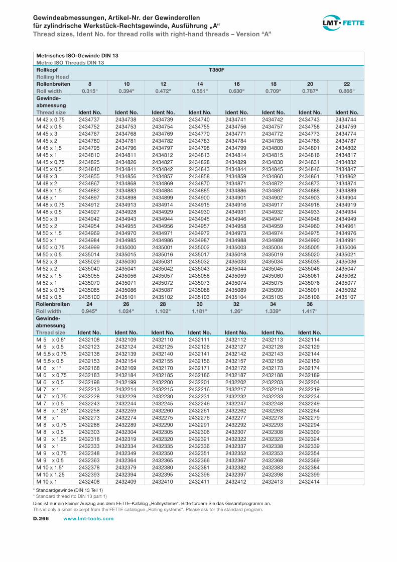
D.266 www.lmt-tools.com
Gewindeabmessungen, Artikel-Nr. der Gewinderollen für zylindrische Werkstück-Rechtsgewinde, Ausführung „A“Thread sizes, Ident No. for thread rolls with right-hand threads – Version “A”
2434737 2434738 2434739 2434740 2434741 2434742 2434743 2434744 2434752 2434753 2434754 2434755 2434756 2434757 2434758 2434759 2434767 2434768 2434769 2434770 2434771 2434772 2434773 2434774 2434780 2434781 2434782 2434783 2434784 2434785 2434786 2434787 2434795 2434796 2434797 2434798 2434799 2434800 2434801 2434802 2434810 2434811 2434812 2434813 2434814 2434815 2434816 2434817 2434825 2434826 2434827 2434828 2434829 2434830 2434831 2434832 2434840 2434841 2434842 2434843 2434844 2434845 2434846 2434847 2434855 2434856 2434857 2434858 2434859 2434860 2434861 2434862 2434867 2434868 2434869 2434870 2434871 2434872 2434873 2434874 2434882 2434883 2434884 2434885 2434886 2434887 2434888 2434889 2434897 2434898 2434899 2434900 2434901 2434902 2434903 2434904 2434912 2434913 2434914 2434915 2434916 2434917 2434918 2434919 2434927 2434928 2434929 2434930 2434931 2434932 2434933 2434934 2434942 2434943 2434944 2434945 2434946 2434947 2434948 2434949 2434954 2434955 2434956 2434957 2434958 2434959 2434960 2434961 2434969 2434970 2434971 2434972 2434973 2434974 2434975 2434976 2434984 2434985 2434986 2434987 2434988 2434989 2434990 2434991 2434999 2435000 2435001 2435002 2435003 2435004 2435005 2435006 2435014 2435015 2435016 2435017 2435018 2435019 2435020 2435021 2435029 2435030 2435031 2435032 2435033 2435034 2435035 2435036 2435040 2435041 2435042 2435043 2435044 2435045 2435046 2435047 2435055 2435056 2435057 2435058 2435059 2435060 2435061 2435062 2435070 2435071 2435072 2435073 2435074 2435075 2435076 2435077 2435085 2435086 2435087 2435088 2435089 2435090 2435091 2435092 2435100 2435101 2435102 2435103 2435104 2435105 2435106 2435107
2432108 2432109 2432110 2432111 2432112 2432113 2432114 2432123 2432124 2432125 2432126 2432127 2432128 2432129 2432138 2432139 2432140 2432141 2432142 2432143 2432144 2432153 2432154 2432155 2432156 2432157 2432158 2432159 2432168 2432169 2432170 2432171 2432172 2432173 2432174 2432183 2432184 2432185 2432186 2432187 2432188 2432189 2432198 2432199 2432200 2432201 2432202 2432203 2432204 2432213 2432214 2432215 2432216 2432217 2432218 2432219 2432228 2432229 2432230 2432231 2432232 2432233 2432234 2432243 2432244 2432245 2432246 2432247 2432248 2432249 2432258 2432259 2432260 2432261 2432262 2432263 2432264 2432273 2432274 2432275 2432276 2432277 2432278 2432279 2432288 2432289 2432290 2432291 2432292 2432293 2432294 2432303 2432304 2432305 2432306 2432307 2432308 2432309 2432318 2432319 2432320 2432321 2432322 2432323 2432324 2432333 2432334 2432335 2432336 2432337 2432338 2432339 2432348 2432349 2432350 2432351 2432352 2432353 2432354 2432363 2432364 2432365 2432366 2432367 2432368 2432369 2432378 2432379 2432380 2432381 2432382 2432383 2432384 2432393 2432394 2432395 2432396 2432397 2432398 2432399 2432408 2432409 2432410 2432411 2432412 2432413 2432414
M 42 x 0,75M 42 x 0,5M 45 x 3M 45 x 2M 45 x 1,5M 45 x 1M 45 x 0,75M 45 x 0,5M 48 x 3M 48 x 2M 48 x 1,5M 48 x 1M 48 x 0,75M 48 x 0,5M 50 x 3M 50 x 2M 50 x 1,5M 50 x 1M 50 x 0,75M 50 x 0,5M 52 x 3M 52 x 2M 52 x 1,5M 52 x 1M 52 x 0,75M 52 x 0,5
M 5 x 0,8*M 5 x 0,5M 5,5 x 0,75M 5,5 x 0,5M 6 x 1*M 6 x 0,75M 6 x 0,5M 7 x 1M 7 x 0,75M 7 x 0,5M 8 x 1,25*M 8 x 1M 8 x 0,75M 8 x 0,5M 9 x 1,25M 9 x 1M 9 x 0,75M 9 x 0,5M 10 x 1,5*M 10 x 1,25M 10 x 1
Metrisches ISO-Gewinde DIN 13Metric ISO Threads DIN 13Rollkopf T350FRolling HeadRollenbreiten 8 10 12 14 16 18 20 22Roll width 0.315" 0.394" 0.472" 0.551" 0.630" 0.709" 0.787" 0.866"Gewinde-abmessungThread size Ident No. Ident No. Ident No. Ident No. Ident No. Ident No. Ident No. Ident No.
Rollenbreiten 24 26 28 30 32 34 36Roll width 0.945" 1.024" 1.102" 1.181" 1.26" 1.339" 1.417"Gewinde-abmessungThread size Ident No. Ident No. Ident No. Ident No. Ident No. Ident No. Ident No.
* Standardgewinde (DIN 13 Teil 1) * Standard thread (to DIN 13 part 1)
Dies ist nur ein kleiner Auszug aus dem FETTE-Katalog „Rollsysteme“. Bitte fordern Sie das Gesamtprogramm an.This is only a small excerpt from the FETTE catalogue „Rolling systems“. Please ask for the standard program.
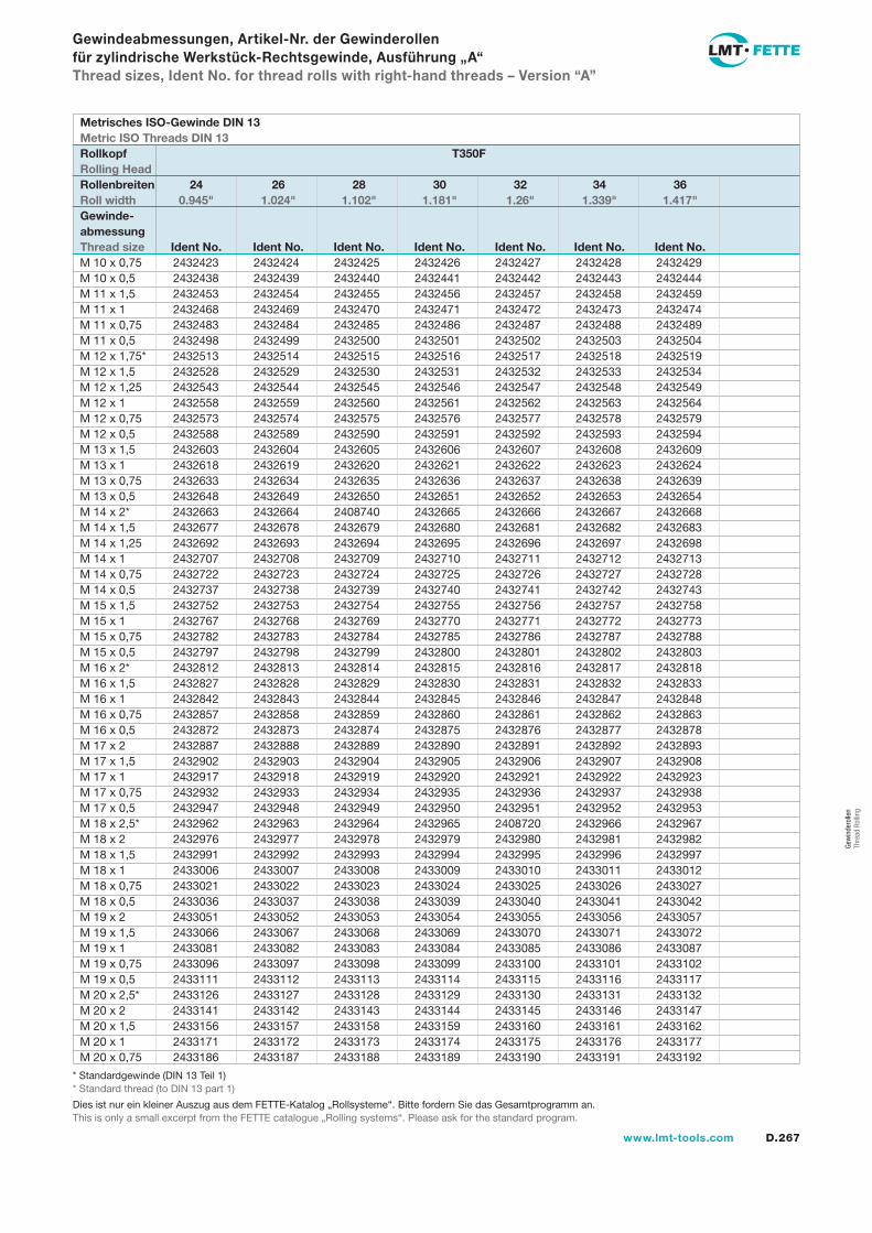
D.267www.lmt-tools.com
Gew
inde
rolle
n Th
read
Rol
ling
Gewindeabmessungen, Artikel-Nr. der Gewinderollen für zylindrische Werkstück-Rechtsgewinde, Ausführung „A“Thread sizes, Ident No. for thread rolls with right-hand threads – Version “A”
2432423 2432424 2432425 2432426 2432427 2432428 2432429 2432438 2432439 2432440 2432441 2432442 2432443 2432444 2432453 2432454 2432455 2432456 2432457 2432458 2432459 2432468 2432469 2432470 2432471 2432472 2432473 2432474 2432483 2432484 2432485 2432486 2432487 2432488 2432489 2432498 2432499 2432500 2432501 2432502 2432503 2432504 2432513 2432514 2432515 2432516 2432517 2432518 2432519 2432528 2432529 2432530 2432531 2432532 2432533 2432534 2432543 2432544 2432545 2432546 2432547 2432548 2432549 2432558 2432559 2432560 2432561 2432562 2432563 2432564 2432573 2432574 2432575 2432576 2432577 2432578 2432579 2432588 2432589 2432590 2432591 2432592 2432593 2432594 2432603 2432604 2432605 2432606 2432607 2432608 2432609 2432618 2432619 2432620 2432621 2432622 2432623 2432624 2432633 2432634 2432635 2432636 2432637 2432638 2432639 2432648 2432649 2432650 2432651 2432652 2432653 2432654 2432663 2432664 2408740 2432665 2432666 2432667 2432668 2432677 2432678 2432679 2432680 2432681 2432682 2432683 2432692 2432693 2432694 2432695 2432696 2432697 2432698 2432707 2432708 2432709 2432710 2432711 2432712 2432713 2432722 2432723 2432724 2432725 2432726 2432727 2432728 2432737 2432738 2432739 2432740 2432741 2432742 2432743 2432752 2432753 2432754 2432755 2432756 2432757 2432758 2432767 2432768 2432769 2432770 2432771 2432772 2432773 2432782 2432783 2432784 2432785 2432786 2432787 2432788 2432797 2432798 2432799 2432800 2432801 2432802 2432803 2432812 2432813 2432814 2432815 2432816 2432817 2432818 2432827 2432828 2432829 2432830 2432831 2432832 2432833 2432842 2432843 2432844 2432845 2432846 2432847 2432848 2432857 2432858 2432859 2432860 2432861 2432862 2432863 2432872 2432873 2432874 2432875 2432876 2432877 2432878 2432887 2432888 2432889 2432890 2432891 2432892 2432893 2432902 2432903 2432904 2432905 2432906 2432907 2432908 2432917 2432918 2432919 2432920 2432921 2432922 2432923 2432932 2432933 2432934 2432935 2432936 2432937 2432938 2432947 2432948 2432949 2432950 2432951 2432952 2432953 2432962 2432963 2432964 2432965 2408720 2432966 2432967 2432976 2432977 2432978 2432979 2432980 2432981 2432982 2432991 2432992 2432993 2432994 2432995 2432996 2432997 2433006 2433007 2433008 2433009 2433010 2433011 2433012 2433021 2433022 2433023 2433024 2433025 2433026 2433027 2433036 2433037 2433038 2433039 2433040 2433041 2433042 2433051 2433052 2433053 2433054 2433055 2433056 2433057 2433066 2433067 2433068 2433069 2433070 2433071 2433072 2433081 2433082 2433083 2433084 2433085 2433086 2433087 2433096 2433097 2433098 2433099 2433100 2433101 2433102 2433111 2433112 2433113 2433114 2433115 2433116 2433117 2433126 2433127 2433128 2433129 2433130 2433131 2433132 2433141 2433142 2433143 2433144 2433145 2433146 2433147 2433156 2433157 2433158 2433159 2433160 2433161 2433162 2433171 2433172 2433173 2433174 2433175 2433176 2433177 2433186 2433187 2433188 2433189 2433190 2433191 2433192
M 10 x 0,75M 10 x 0,5M 11 x 1,5M 11 x 1M 11 x 0,75M 11 x 0,5M 12 x 1,75*M 12 x 1,5M 12 x 1,25M 12 x 1M 12 x 0,75M 12 x 0,5M 13 x 1,5M 13 x 1M 13 x 0,75M 13 x 0,5M 14 x 2*M 14 x 1,5M 14 x 1,25M 14 x 1M 14 x 0,75M 14 x 0,5M 15 x 1,5M 15 x 1M 15 x 0,75M 15 x 0,5M 16 x 2*M 16 x 1,5M 16 x 1M 16 x 0,75M 16 x 0,5M 17 x 2M 17 x 1,5M 17 x 1M 17 x 0,75M 17 x 0,5M 18 x 2,5*M 18 x 2M 18 x 1,5M 18 x 1M 18 x 0,75M 18 x 0,5M 19 x 2M 19 x 1,5M 19 x 1M 19 x 0,75M 19 x 0,5M 20 x 2,5*M 20 x 2M 20 x 1,5M 20 x 1M 20 x 0,75
Metrisches ISO-Gewinde DIN 13Metric ISO Threads DIN 13Rollkopf T350FRolling HeadRollenbreiten 24 26 28 30 32 34 36Roll width 0.945" 1.024" 1.102" 1.181" 1.26" 1.339" 1.417"Gewinde-abmessungThread size Ident No. Ident No. Ident No. Ident No. Ident No. Ident No. Ident No.
* Standardgewinde (DIN 13 Teil 1) * Standard thread (to DIN 13 part 1)
Dies ist nur ein kleiner Auszug aus dem FETTE-Katalog „Rollsysteme“. Bitte fordern Sie das Gesamtprogramm an.This is only a small excerpt from the FETTE catalogue „Rolling systems“. Please ask for the standard program.
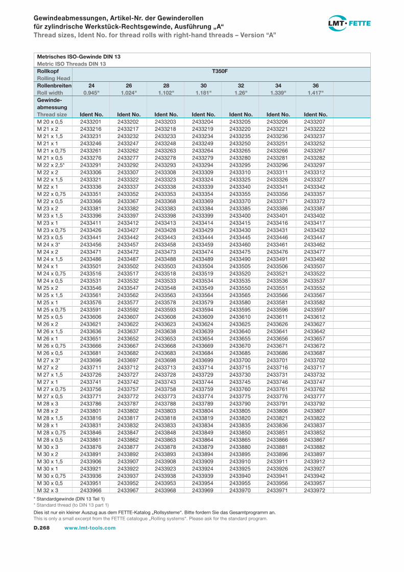
D.268 www.lmt-tools.com
Gewindeabmessungen, Artikel-Nr. der Gewinderollen für zylindrische Werkstück-Rechtsgewinde, Ausführung „A“Thread sizes, Ident No. for thread rolls with right-hand threads – Version “A”
2433201 2433202 2433203 2433204 2433205 2433206 2433207 2433216 2433217 2433218 2433219 2433220 2433221 2433222 2433231 2433232 2433233 2433234 2433235 2433236 2433237 2433246 2433247 2433248 2433249 2433250 2433251 2433252 2433261 2433262 2433263 2433264 2433265 2433266 2433267 2433276 2433277 2433278 2433279 2433280 2433281 2433282 2433291 2433292 2433293 2433294 2433295 2433296 2433297 2433306 2433307 2433308 2433309 2433310 2433311 2433312 2433321 2433322 2433323 2433324 2433325 2433326 2433327 2433336 2433337 2433338 2433339 2433340 2433341 2433342 2433351 2433352 2433353 2433354 2433355 2433356 2433357 2433366 2433367 2433368 2433369 2433370 2433371 2433372 2433381 2433382 2433383 2433384 2433385 2433386 2433387 2433396 2433397 2433398 2433399 2433400 2433401 2433402 2433411 2433412 2433413 2433414 2433415 2433416 2433417 2433426 2433427 2433428 2433429 2433430 2433431 2433432 2433441 2433442 2433443 2433444 2433445 2433446 2433447 2433456 2433457 2433458 2433459 2433460 2433461 2433462 2433471 2433472 2433473 2433474 2433475 2433476 2433477 2433486 2433487 2433488 2433489 2433490 2433491 2433492 2433501 2433502 2433503 2433504 2433505 2433506 2433507 2433516 2433517 2433518 2433519 2433520 2433521 2433522 2433531 2433532 2433533 2433534 2433535 2433536 2433537 2433546 2433547 2433548 2433549 2433550 2433551 2433552 2433561 2433562 2433563 2433564 2433565 2433566 2433567 2433576 2433577 2433578 2433579 2433580 2433581 2433582 2433591 2433592 2433593 2433594 2433595 2433596 2433597 2433606 2433607 2433608 2433609 2433610 2433611 2433612 2433621 2433622 2433623 2433624 2433625 2433626 2433627 2433636 2433637 2433638 2433639 2433640 2433641 2433642 2433651 2433652 2433653 2433654 2433655 2433656 2433657 2433666 2433667 2433668 2433669 2433670 2433671 2433672 2433681 2433682 2433683 2433684 2433685 2433686 2433687 2433696 2433697 2433698 2433699 2433700 2433701 2433702 2433711 2433712 2433713 2433714 2433715 2433716 2433717 2433726 2433727 2433728 2433729 2433730 2433731 2433732 2433741 2433742 2433743 2433744 2433745 2433746 2433747 2433756 2433757 2433758 2433759 2433760 2433761 2433762 2433771 2433772 2433773 2433774 2433775 2433776 2433777 2433786 2433787 2433788 2433789 2433790 2433791 2433792 2433801 2433802 2433803 2433804 2433805 2433806 2433807 2433816 2433817 2433818 2433819 2433820 2433821 2433822 2433831 2433832 2433833 2433834 2433835 2433836 2433837 2433846 2433847 2433848 2433849 2433850 2433851 2433852 2433861 2433862 2433863 2433864 2433865 2433866 2433867 2433876 2433877 2433878 2433879 2433880 2433881 2433882 2433891 2433892 2433893 2433894 2433895 2433896 2433897 2433906 2433907 2433908 2433909 2433910 2433911 2433912 2433921 2433922 2433923 2433924 2433925 2433926 2433927 2433936 2433937 2433938 2433939 2433940 2433941 2433942 2433951 2433952 2433953 2433954 2433955 2433956 2433957 2433966 2433967 2433968 2433969 2433970 2433971 2433972
M 20 x 0,5M 21 x 2M 21 x 1,5M 21 x 1M 21 x 0,75M 21 x 0,5M 22 x 2,5*M 22 x 2M 22 x 1,5M 22 x 1M 22 x 0,75M 22 x 0,5M 23 x 2M 23 x 1,5M 23 x 1M 23 x 0,75M 23 x 0,5M 24 x 3*M 24 x 2M 24 x 1,5M 24 x 1M 24 x 0,75M 24 x 0,5M 25 x 2M 25 x 1,5M 25 x 1M 25 x 0,75M 25 x 0,5M 26 x 2M 26 x 1,5M 26 x 1M 26 x 0,75M 26 x 0,5M 27 x 3*M 27 x 2M 27 x 1,5M 27 x 1M 27 x 0,75M 27 x 0,5M 28 x 3M 28 x 2M 28 x 1,5M 28 x 1M 28 x 0,75M 28 x 0,5M 30 x 3M 30 x 2M 30 x 1,5M 30 x 1M 30 x 0,75M 30 x 0,5M 32 x 3
Metrisches ISO-Gewinde DIN 13Metric ISO Threads DIN 13Rollkopf T350FRolling HeadRollenbreiten 24 26 28 30 32 34 36Roll width 0.945" 1.024" 1.102" 1.181" 1.26" 1.339" 1.417"Gewinde-abmessungThread size Ident No. Ident No. Ident No. Ident No. Ident No. Ident No. Ident No.
* Standardgewinde (DIN 13 Teil 1) * Standard thread (to DIN 13 part 1)
Dies ist nur ein kleiner Auszug aus dem FETTE-Katalog „Rollsysteme“. Bitte fordern Sie das Gesamtprogramm an.This is only a small excerpt from the FETTE catalogue „Rolling systems“. Please ask for the standard program.
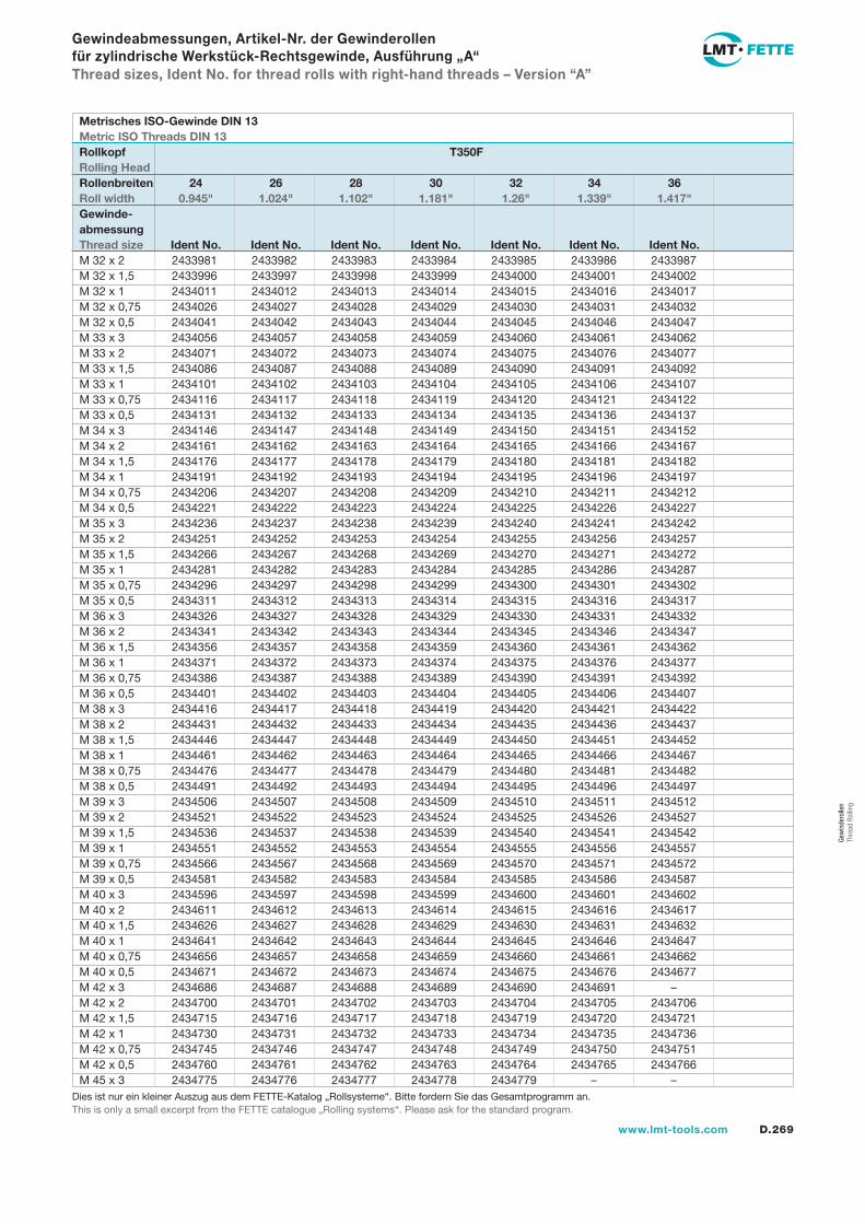
D.269www.lmt-tools.com
Gew
inde
rolle
n Th
read
Rol
ling
Gewindeabmessungen, Artikel-Nr. der Gewinderollen für zylindrische Werkstück-Rechtsgewinde, Ausführung „A“Thread sizes, Ident No. for thread rolls with right-hand threads – Version “A”
2433981 2433982 2433983 2433984 2433985 2433986 2433987 2433996 2433997 2433998 2433999 2434000 2434001 2434002 2434011 2434012 2434013 2434014 2434015 2434016 2434017 2434026 2434027 2434028 2434029 2434030 2434031 2434032 2434041 2434042 2434043 2434044 2434045 2434046 2434047 2434056 2434057 2434058 2434059 2434060 2434061 2434062 2434071 2434072 2434073 2434074 2434075 2434076 2434077 2434086 2434087 2434088 2434089 2434090 2434091 2434092 2434101 2434102 2434103 2434104 2434105 2434106 2434107 2434116 2434117 2434118 2434119 2434120 2434121 2434122 2434131 2434132 2434133 2434134 2434135 2434136 2434137 2434146 2434147 2434148 2434149 2434150 2434151 2434152 2434161 2434162 2434163 2434164 2434165 2434166 2434167 2434176 2434177 2434178 2434179 2434180 2434181 2434182 2434191 2434192 2434193 2434194 2434195 2434196 2434197 2434206 2434207 2434208 2434209 2434210 2434211 2434212 2434221 2434222 2434223 2434224 2434225 2434226 2434227 2434236 2434237 2434238 2434239 2434240 2434241 2434242 2434251 2434252 2434253 2434254 2434255 2434256 2434257 2434266 2434267 2434268 2434269 2434270 2434271 2434272 2434281 2434282 2434283 2434284 2434285 2434286 2434287 2434296 2434297 2434298 2434299 2434300 2434301 2434302 2434311 2434312 2434313 2434314 2434315 2434316 2434317 2434326 2434327 2434328 2434329 2434330 2434331 2434332 2434341 2434342 2434343 2434344 2434345 2434346 2434347 2434356 2434357 2434358 2434359 2434360 2434361 2434362 2434371 2434372 2434373 2434374 2434375 2434376 2434377 2434386 2434387 2434388 2434389 2434390 2434391 2434392 2434401 2434402 2434403 2434404 2434405 2434406 2434407 2434416 2434417 2434418 2434419 2434420 2434421 2434422 2434431 2434432 2434433 2434434 2434435 2434436 2434437 2434446 2434447 2434448 2434449 2434450 2434451 2434452 2434461 2434462 2434463 2434464 2434465 2434466 2434467 2434476 2434477 2434478 2434479 2434480 2434481 2434482 2434491 2434492 2434493 2434494 2434495 2434496 2434497 2434506 2434507 2434508 2434509 2434510 2434511 2434512 2434521 2434522 2434523 2434524 2434525 2434526 2434527 2434536 2434537 2434538 2434539 2434540 2434541 2434542 2434551 2434552 2434553 2434554 2434555 2434556 2434557 2434566 2434567 2434568 2434569 2434570 2434571 2434572 2434581 2434582 2434583 2434584 2434585 2434586 2434587 2434596 2434597 2434598 2434599 2434600 2434601 2434602 2434611 2434612 2434613 2434614 2434615 2434616 2434617 2434626 2434627 2434628 2434629 2434630 2434631 2434632 2434641 2434642 2434643 2434644 2434645 2434646 2434647 2434656 2434657 2434658 2434659 2434660 2434661 2434662 2434671 2434672 2434673 2434674 2434675 2434676 2434677 2434686 2434687 2434688 2434689 2434690 2434691 – 2434700 2434701 2434702 2434703 2434704 2434705 2434706 2434715 2434716 2434717 2434718 2434719 2434720 2434721 2434730 2434731 2434732 2434733 2434734 2434735 2434736 2434745 2434746 2434747 2434748 2434749 2434750 2434751 2434760 2434761 2434762 2434763 2434764 2434765 2434766 2434775 2434776 2434777 2434778 2434779 – –
M 32 x 2M 32 x 1,5M 32 x 1M 32 x 0,75M 32 x 0,5M 33 x 3M 33 x 2M 33 x 1,5M 33 x 1M 33 x 0,75M 33 x 0,5M 34 x 3M 34 x 2M 34 x 1,5M 34 x 1M 34 x 0,75M 34 x 0,5M 35 x 3M 35 x 2M 35 x 1,5M 35 x 1M 35 x 0,75M 35 x 0,5M 36 x 3M 36 x 2M 36 x 1,5M 36 x 1M 36 x 0,75M 36 x 0,5M 38 x 3M 38 x 2M 38 x 1,5M 38 x 1M 38 x 0,75M 38 x 0,5M 39 x 3M 39 x 2M 39 x 1,5M 39 x 1M 39 x 0,75M 39 x 0,5M 40 x 3M 40 x 2M 40 x 1,5M 40 x 1M 40 x 0,75M 40 x 0,5M 42 x 3M 42 x 2M 42 x 1,5M 42 x 1M 42 x 0,75M 42 x 0,5M 45 x 3
Metrisches ISO-Gewinde DIN 13Metric ISO Threads DIN 13Rollkopf T350FRolling HeadRollenbreiten 24 26 28 30 32 34 36Roll width 0.945" 1.024" 1.102" 1.181" 1.26" 1.339" 1.417"Gewinde-abmessungThread size Ident No. Ident No. Ident No. Ident No. Ident No. Ident No. Ident No.
Dies ist nur ein kleiner Auszug aus dem FETTE-Katalog „Rollsysteme“. Bitte fordern Sie das Gesamtprogramm an.This is only a small excerpt from the FETTE catalogue „Rolling systems“. Please ask for the standard program.
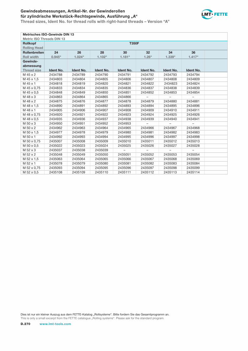
D.270 www.lmt-tools.com
Dies ist nur ein kleiner Auszug aus dem FETTE-Katalog „Rollsysteme“. Bitte fordern Sie das Gesamtprogramm an.This is only a small excerpt from the FETTE catalogue „Rolling systems“. Please ask for the standard program.
Gewindeabmessungen, Artikel-Nr. der Gewinderollen für zylindrische Werkstück-Rechtsgewinde, Ausführung „A“Thread sizes, Ident No. for thread rolls with right-hand threads – Version “A”
2434788 2434789 2434790 2434791 2434792 2434793 2434794 2434803 2434804 2434805 2434806 2434807 2434808 2434809 2434818 2434819 2434820 2434821 2434822 2434823 2434824 2434833 2434834 2434835 2434836 2434837 2434838 2434839 2434848 2434849 2434850 2434851 2434852 2434853 2434854 2434863 2434864 2434865 2434866 – – – 2434875 2434876 2434877 2434878 2434879 2434880 2434881 2434890 2434891 2434892 2434893 2434894 2434895 2434896 2434905 2434906 2434907 2434908 2434909 2434910 2434911 2434920 2434921 2434922 2434923 2434924 2434925 2434926 2434935 2434936 2434937 2434938 2434939 2434940 2434941 2434950 2434951 2434952 2434953 – – – 2434962 2434963 2434964 2434965 2434966 2434967 2434968 2434977 2434978 2434979 2434980 2434981 2434982 2434983 2434992 2434993 2434994 2434995 2434996 2434997 2434998 2435007 2435008 2435009 2435010 2435011 2435012 2435013 2435022 2435023 2435024 2435025 2435026 2435027 2435028 2435037 2435038 2435039 – – – – 2435048 2435049 2435050 2435051 2435052 2435053 2435054 2435063 2435064 2435065 2435066 2435067 2435068 2435069 2435078 2435079 2435080 2435081 2435082 2435083 2435084 2435093 2435094 2435095 2435096 2435097 2435098 2435099 2435108 2435109 2435110 2435111 2435112 2435113 2435114
M 45 x 2M 45 x 1,5M 45 x 1M 45 x 0,75M 45 x 0,5M 48 x 3M 48 x 2M 48 x 1,5M 48 x 1M 48 x 0,75M 48 x 0,5M 50 x 3M 50 x 2M 50 x 1,5M 50 x 1M 50 x 0,75M 50 x 0,5M 52 x 3M 52 x 2M 52 x 1,5M 52 x 1M 52 x 0,75M 52 x 0,5
Metrisches ISO-Gewinde DIN 13Metric ISO Threads DIN 13Rollkopf T350FRolling HeadRollenbreiten 24 26 28 30 32 34 36Roll width 0.945" 1.024" 1.102" 1.181" 1.26" 1.339" 1.417"Gewinde-abmessungThread size Ident No. Ident No. Ident No. Ident No. Ident No. Ident No. Ident No.
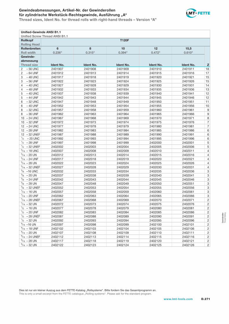
D.271www.lmt-tools.com
Gew
inde
rolle
n Th
read
Rol
ling
2401907 2401908 2401909 2401910 2401911 18 2401912 2401913 2401914 2401915 2401916 17 2401917 2401918 2401919 2401920 2401921 15 2401922 2401923 2401924 2401925 2401926 15 2401927 2401928 2401929 2401930 2401931 14 2401932 2401933 2401934 2401935 2401936 13 2401937 2401938 2401939 2401940 2401941 12 2401942 2401943 2401944 2401945 2401946 12 2401947 2401948 2401949 2401950 2401951 11 2401952 2401953 2401954 2401955 2401956 10 2401957 2401958 2401959 2401960 2401961 9 2401962 2401963 2401964 2401965 2401966 9 2401967 2401968 2401969 2401970 2401971 8 2401972 2401973 2401974 2401975 2401976 7 2401977 2401978 2401979 2401980 2401981 7 2401982 2401983 2401984 2401985 2401986 6 2401987 2401988 2401989 2401990 2401991 6 2401992 2401993 2401994 2401995 2401996 6 2401997 2401998 2401999 2402000 2402001 5 2402002 2402003 2402004 2402005 2402006 5 2402007 2402008 2402009 2402010 2402011 4 2402012 2402013 2402014 2402015 2402016 4 2402017 2402018 2402019 2402020 2402021 4 2402022 2402023 2402024 2402025 2402026 4 2402027 2402028 2402029 2402030 2402031 4 2402032 2402033 2402034 2402035 2402036 3 2402037 2402038 2402039 2402040 2402041 3 2402042 2402043 2402044 2402045 2402046 3 2402047 2402048 2402049 2402050 2402051 3 2402052 2402053 2402054 2402055 2402056 3 2402057 2402058 2402059 2402060 2402061 3 2402062 2402063 2402064 2402065 2402066 3 2402067 2402068 2402069 2402070 2402071 2 2402072 2402073 2402074 2402075 2402076 2 2402077 2402078 2402079 2402080 2402081 2 2402082 2402083 2402084 2402085 2402086 2 2402087 2402088 2402089 2402090 2402091 2 2402092 2402093 2402094 2402095 2402096 2 2402097 2402098 2402099 2402100 2402101 2 2402102 2402103 2402104 2402105 2402106 2 2402107 2402108 2402109 2402110 2402111 2 2402112 2402113 2402114 2402115 2402116 2 2402117 2402118 2402119 2402120 2402121 2 2402122 2402123 2402124 2402125 2402126 2
2 – 56 UNC2 – 64 UNF3 – 48 UNC3 – 56 UNF4 – 40 UNC4 – 48 UNF5 – 40 UNC5 – 44 UNF6 – 32 UNC6 – 40 UNF8 – 32 UNC8 – 36 UNF10 – 24 UNC10 – 32 UNF12 – 24 UNC12 – 28 UNF12 – 32 UNEF1/4 – 20 UNC1/4 – 28 UNF1/4 – 32 UNEF5/16 – 18 UNC5/16 – 20 UN5/16 – 24 UNF5/16 – 28 UN5/16 – 32 UNEF3/8 –16 UNC3/8 – 20 UN3/8 – 24 UNF3/8 – 28 UN3/8 – 32 UNEF7/16 – 16 UN7/16 – 20 UNF7/16 – 28 UNEF7/16 – 32 UN1/2 – 16 UN1/2 – 20 UNF1/2 – 28 UNEF1/2 – 32 UN9/16 –16 UN9/16 – 18 UNF9/16 – 20 UN9/16 – 24 UNEF9/16 – 28 UN9/16 – 32 UN
Gewindeabmessungen, Artikel-Nr. der Gewinderollen für zylindrische Werkstück-Rechtsgewinde, Ausführung „A“Thread sizes, Ident No. for thread rolls with right-hand threads – Version “A”
Unified-Gewinde ANSI B1.1Unified Screw Thread ANSI B1.1Rollkopf T120FRolling HeadRollenbreiten 6 8 10 12 15,5Roll width 0.236" 0.315" 0.394" 0.472" 0.610"Gewinde-abmessungThread size Ident No. Ident No. Ident No. Ident No. Ident No. Z
Dies ist nur ein kleiner Auszug aus dem FETTE-Katalog „Rollsysteme“. Bitte fordern Sie das Gesamtprogramm an.This is only a small excerpt from the FETTE catalogue „Rolling systems“. Please ask for the standard program.
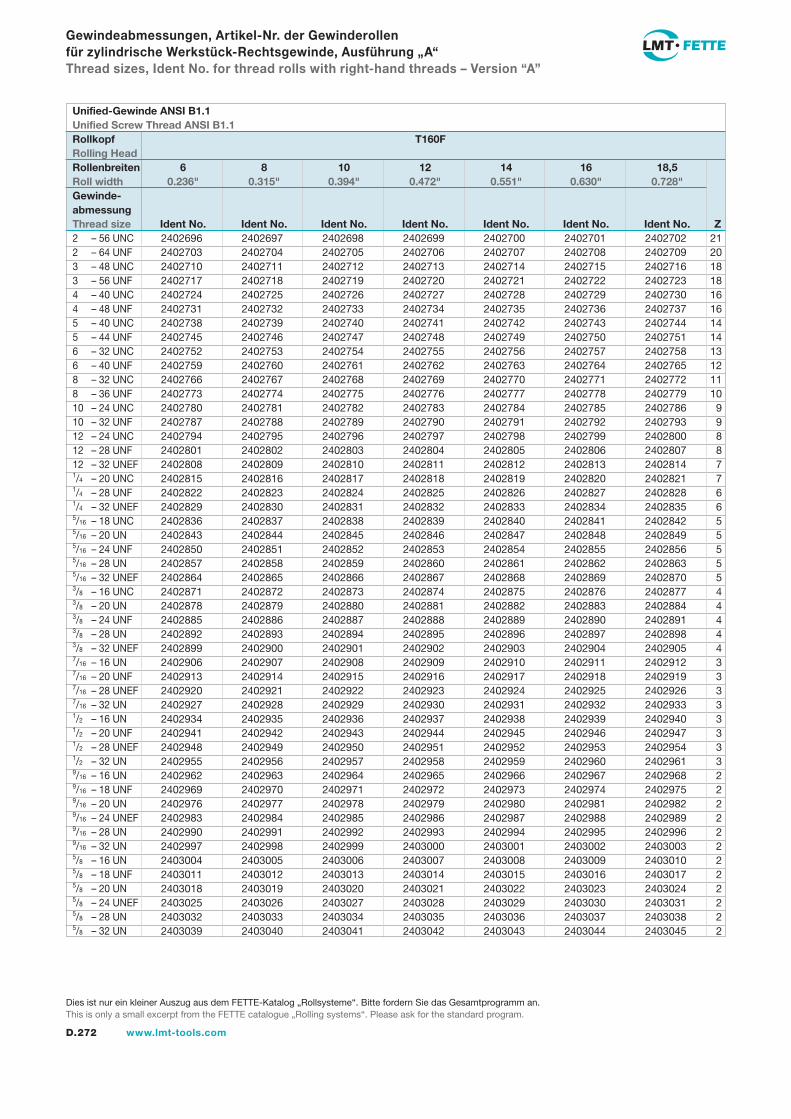
D.272 www.lmt-tools.com
2 – 56 UNC2 – 64 UNF3 – 48 UNC3 – 56 UNF4 – 40 UNC4 – 48 UNF5 – 40 UNC5 – 44 UNF6 – 32 UNC6 – 40 UNF8 – 32 UNC8 – 36 UNF10 – 24 UNC10 – 32 UNF12 – 24 UNC12 – 28 UNF12 – 32 UNEF1/4 – 20 UNC1/4 – 28 UNF1/4 – 32 UNEF5/16 – 18 UNC5/16 – 20 UN5/16 – 24 UNF5/16 – 28 UN5/16 – 32 UNEF3/8 – 16 UNC3/8 – 20 UN3/8 – 24 UNF3/8 – 28 UN3/8 – 32 UNEF7/16 – 16 UN7/16 – 20 UNF7/16 – 28 UNEF7/16 – 32 UN1/2 – 16 UN1/2 – 20 UNF1/2 – 28 UNEF1/2 – 32 UN9/16 – 16 UN9/16 – 18 UNF9/16 – 20 UN9/16 – 24 UNEF9/16 – 28 UN9/16 – 32 UN5/8 – 16 UN5/8 – 18 UNF5/8 – 20 UN5/8 – 24 UNEF5/8 – 28 UN5/8 – 32 UN
2402696 2402697 2402698 2402699 2402700 2402701 2402702 21 2402703 2402704 2402705 2402706 2402707 2402708 2402709 20 2402710 2402711 2402712 2402713 2402714 2402715 2402716 18 2402717 2402718 2402719 2402720 2402721 2402722 2402723 18 2402724 2402725 2402726 2402727 2402728 2402729 2402730 16 2402731 2402732 2402733 2402734 2402735 2402736 2402737 16 2402738 2402739 2402740 2402741 2402742 2402743 2402744 14 2402745 2402746 2402747 2402748 2402749 2402750 2402751 14 2402752 2402753 2402754 2402755 2402756 2402757 2402758 13 2402759 2402760 2402761 2402762 2402763 2402764 2402765 12 2402766 2402767 2402768 2402769 2402770 2402771 2402772 11 2402773 2402774 2402775 2402776 2402777 2402778 2402779 10 2402780 2402781 2402782 2402783 2402784 2402785 2402786 9 2402787 2402788 2402789 2402790 2402791 2402792 2402793 9 2402794 2402795 2402796 2402797 2402798 2402799 2402800 8 2402801 2402802 2402803 2402804 2402805 2402806 2402807 8 2402808 2402809 2402810 2402811 2402812 2402813 2402814 7 2402815 2402816 2402817 2402818 2402819 2402820 2402821 7 2402822 2402823 2402824 2402825 2402826 2402827 2402828 6 2402829 2402830 2402831 2402832 2402833 2402834 2402835 6 2402836 2402837 2402838 2402839 2402840 2402841 2402842 5 2402843 2402844 2402845 2402846 2402847 2402848 2402849 5 2402850 2402851 2402852 2402853 2402854 2402855 2402856 5 2402857 2402858 2402859 2402860 2402861 2402862 2402863 5 2402864 2402865 2402866 2402867 2402868 2402869 2402870 5 2402871 2402872 2402873 2402874 2402875 2402876 2402877 4 2402878 2402879 2402880 2402881 2402882 2402883 2402884 4 2402885 2402886 2402887 2402888 2402889 2402890 2402891 4 2402892 2402893 2402894 2402895 2402896 2402897 2402898 4 2402899 2402900 2402901 2402902 2402903 2402904 2402905 4 2402906 2402907 2402908 2402909 2402910 2402911 2402912 3 2402913 2402914 2402915 2402916 2402917 2402918 2402919 3 2402920 2402921 2402922 2402923 2402924 2402925 2402926 3 2402927 2402928 2402929 2402930 2402931 2402932 2402933 3 2402934 2402935 2402936 2402937 2402938 2402939 2402940 3 2402941 2402942 2402943 2402944 2402945 2402946 2402947 3 2402948 2402949 2402950 2402951 2402952 2402953 2402954 3 2402955 2402956 2402957 2402958 2402959 2402960 2402961 3 2402962 2402963 2402964 2402965 2402966 2402967 2402968 2 2402969 2402970 2402971 2402972 2402973 2402974 2402975 2 2402976 2402977 2402978 2402979 2402980 2402981 2402982 2 2402983 2402984 2402985 2402986 2402987 2402988 2402989 2 2402990 2402991 2402992 2402993 2402994 2402995 2402996 2 2402997 2402998 2402999 2403000 2403001 2403002 2403003 2 2403004 2403005 2403006 2403007 2403008 2403009 2403010 2 2403011 2403012 2403013 2403014 2403015 2403016 2403017 2 2403018 2403019 2403020 2403021 2403022 2403023 2403024 2 2403025 2403026 2403027 2403028 2403029 2403030 2403031 2 2403032 2403033 2403034 2403035 2403036 2403037 2403038 2 2403039 2403040 2403041 2403042 2403043 2403044 2403045 2
Gewindeabmessungen, Artikel-Nr. der Gewinderollen für zylindrische Werkstück-Rechtsgewinde, Ausführung „A“Thread sizes, Ident No. for thread rolls with right-hand threads – Version “A”
Unified-Gewinde ANSI B1.1Unified Screw Thread ANSI B1.1Rollkopf T160FRolling HeadRollenbreiten 6 8 10 12 14 16 18,5Roll width 0.236" 0.315" 0.394" 0.472" 0.551" 0.630" 0.728"Gewinde-abmessungThread size Ident No. Ident No. Ident No. Ident No. Ident No. Ident No. Ident No. Z
Dies ist nur ein kleiner Auszug aus dem FETTE-Katalog „Rollsysteme“. Bitte fordern Sie das Gesamtprogramm an.This is only a small excerpt from the FETTE catalogue „Rolling systems“. Please ask for the standard program.
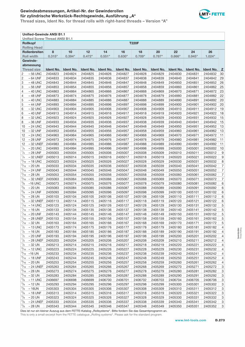
D.273www.lmt-tools.com
Gew
inde
rolle
n Th
read
Rol
ling
2404823 2404824 2404825 2404826 2404827 2404828 2404829 2404830 2404831 2404832 30 2404833 2404834 2404835 2404836 2404837 2404838 2404839 2404840 2404841 2404842 29 2404843 2404844 2404845 2404846 2404847 2404848 2404849 2404850 2404851 2404852 26 2404853 2404854 2404855 2404856 2404857 2404858 2404859 2404860 2404861 2404862 25 2404863 2404864 2404865 2404866 2404867 2404868 2404869 2404870 2404871 2404872 23 2404873 2404874 2404875 2404876 2404877 2404878 2404879 2404880 2404881 2404882 22 2404883 2404884 2404885 2404886 2404887 2404888 2404889 2404890 2404891 2404892 20 2404893 2404894 2404895 2404896 2404897 2404898 2404899 2404900 2404901 2404902 20 2404903 2404904 2404905 2404906 2404907 2404908 2404909 2404910 2404911 2404912 19 2404913 2404914 2404915 2404916 2404917 2404918 2404919 2404920 2404921 2404922 18 2404923 2404924 2404925 2404926 2404927 2404928 2404929 2404930 2404931 2404932 15 2404933 2404934 2404935 2404936 2404937 2404938 2404939 2404940 2404941 2404942 15 2404943 2404944 2404945 2404946 2404947 2404948 2404949 2404950 2404951 2404952 13 2404953 2404954 2404955 2404956 2404957 2404958 2404959 2404960 2404961 2404962 13 2404963 2404964 2404965 2404966 2404967 2404968 2404969 2404970 2404971 2404972 11 2404973 2404974 2404975 2404976 2404977 2404978 2404979 2404980 2404981 2404982 11 2404983 2404984 2404985 2404986 2404987 2404988 2404989 2404990 2404991 2404992 11 2404993 2404994 2404995 2404996 2404997 2404998 2404999 2405000 2405001 2405002 10 2405003 2405004 2405005 2405006 2405007 2405008 2405009 2405010 2405011 2405012 9 2405013 2405014 2405015 2405016 2405017 2405018 2405019 2405020 2405021 2405022 9 2405023 2405024 2405025 2405026 2405027 2405028 2405029 2405030 2405031 2405032 8 2405033 2405034 2405035 2405036 2405037 2405038 2405039 2405040 2405041 2405042 7 2405043 2405044 2405045 2405046 2405047 2405048 2405049 2405050 2405051 2405052 7 2405053 2405054 2405055 2405056 2405057 2405058 2405059 2405060 2405061 2405062 7 2405063 2405064 2405065 2405066 2405067 2405068 2405069 2405070 2405071 2405072 7 2405073 2405074 2405075 2405076 2405077 2405078 2405079 2405080 2405081 2405082 6 2405083 2405084 2405085 2405086 2405087 2405088 2405089 2405090 2405091 2405092 6 2405093 2405094 2405095 2405096 2405097 2405098 2405099 2405100 2405101 2405102 6 2405103 2405104 2405105 2405106 2405107 2405108 2405109 2405110 2405111 2405112 6 2405113 2405114 2405115 2405116 2405117 2405118 2405119 2405120 2405121 2405122 6 2405123 2405124 2405125 2405126 2405127 2405128 2405129 2405130 2405131 2405132 5 2405133 2405134 2405135 2405136 2405137 2405138 2405139 2405140 2405141 2405142 5 2405143 2405144 2405145 2405146 2405147 2405148 2405149 2405150 2405151 2405152 5 2405153 2405154 2405155 2405156 2405157 2405158 2405159 2405160 2405161 2405162 5 2405163 2405164 2405165 2405166 2405167 2405168 2405169 2405170 2405171 2405172 5 2405173 2405174 2405175 2405176 2405177 2405178 2405179 2405180 2405181 2405182 4 2405183 2405184 2405185 2405186 2405187 2405188 2405189 2405190 2405191 2405192 4 2405193 2405194 2405195 2405196 2405197 2405198 2405199 2405200 2405201 2405202 4 2405203 2405204 2405205 2405206 2405207 2405208 2405209 2405210 2405211 2405212 4 2405213 2405214 2405215 2405216 2405217 2405218 2405219 2405220 2405221 2405222 4 2405223 2405224 2405225 2405226 2405227 2405228 2405229 2405230 2405231 2405232 4 2405233 2405234 2405235 2405236 2405237 2405238 2405239 2405240 2405241 2405242 4 2405243 2405244 2405245 2405246 2405247 2405248 2405249 2405250 2405251 2405252 4 2405253 2405254 2405255 2405256 2405257 2405258 2405259 2405260 2405261 2405262 4 2405263 2405264 2405265 2405266 2405267 2405268 2405269 2405270 2405271 2405272 3 2405273 2405274 2405275 2405276 2405277 2405278 2405279 2405280 2405281 2405282 3 2405283 2405284 2405285 2405286 2405287 2405288 2405289 2405290 2405291 2405292 3 2406697 2406698 2406699 2406700 2406701 2406702 2406703 2406704 2406705 2406706 3 2405293 2405294 2405295 2405296 2405297 2405298 2405299 2405300 2405301 2405302 3 2405303 2405304 2405305 2405306 2405307 2405308 2405309 2405310 2405311 2405312 3 2405313 2405314 2405315 2405316 2405317 2405318 2405319 2405320 2405321 2405322 3 2405323 2405324 2405325 2405326 2405327 2405328 2405329 2405330 2405331 2405332 3 2405333 2405334 2405335 2405336 2405337 2405338 2405339 2405340 2405341 2405342 3 2405343 2405344 2405345 2405346 2405347 2405348 2405349 2405350 2405351 2405352 3
Gewindeabmessungen, Artikel-Nr. der Gewinderollen für zylindrische Werkstück-Rechtsgewinde, Ausführung „A“Thread sizes, Ident No. for thread rolls with right-hand threads – Version “A”
2 – 56 UNC2 – 64 UNF3 – 48 UNC3 – 56 UNF4 – 40 UNC4 – 48 UNF5 – 40 UNC5 – 44 UNF6 – 32 UNC6 – 40 UNF8 – 32 UNC8 – 36 UNF10 – 24 UNC10 – 32 UNF12 – 24 UNC12 – 28 UNF12 – 32 UNEF1/4 – 20 UNC1/4 – 28 UNF1/4 – 32 UNEF5/16 – 18 UNC5/16 – 20 UN5/16 – 24 UNF5/16 – 28 UN5/16 – 32 UNEF3/8 –16 UNC3/8 – 20 UN3/8 – 24 UNF3/8 – 28 UN3/8 – 32 UNEF7/16 – 14 UNC7/16 – 16 UN7/16 – 20 UNF7/16 – 28 UNEF7/16 – 32 UN1/2 – 13 UNC1/2 – 16 UN1/2 – 20 UNF1/2 – 28 UNEF1/2 – 32 UN9/16 – 12 UNC9/16 –16 UN9/16 – 18 UNF9/16 – 20 UN9/16 – 24 UNEF9/16 – 28 UN9/16 – 32 UN5/8 – 11 UNC5/8 – 12 UN5/8 – 16UN5/8 – 18 UNF5/8 – 20 UN5/8 – 24 UNEF5/8 – 28 UN
Unified-Gewinde ANSI B1.1Unified Screw Thread ANSI B1.1Rollkopf T220FRolling HeadRollenbreiten 8 10 12 14 16 18 20 22 24 26Roll width 0.315" 0.394" 0.472" 0.551" 0.630" 0.709" 0.787" 0.866" 0.945" 1.024"Gewinde-abmessungThread size Ident No. Ident No. Ident No. Ident No. Ident No. Ident No. Ident No. Ident No. Ident No. Ident No. Z
Dies ist nur ein kleiner Auszug aus dem FETTE-Katalog „Rollsysteme“. Bitte fordern Sie das Gesamtprogramm an.This is only a small excerpt from the FETTE catalogue „Rolling systems“. Please ask for the standard program.
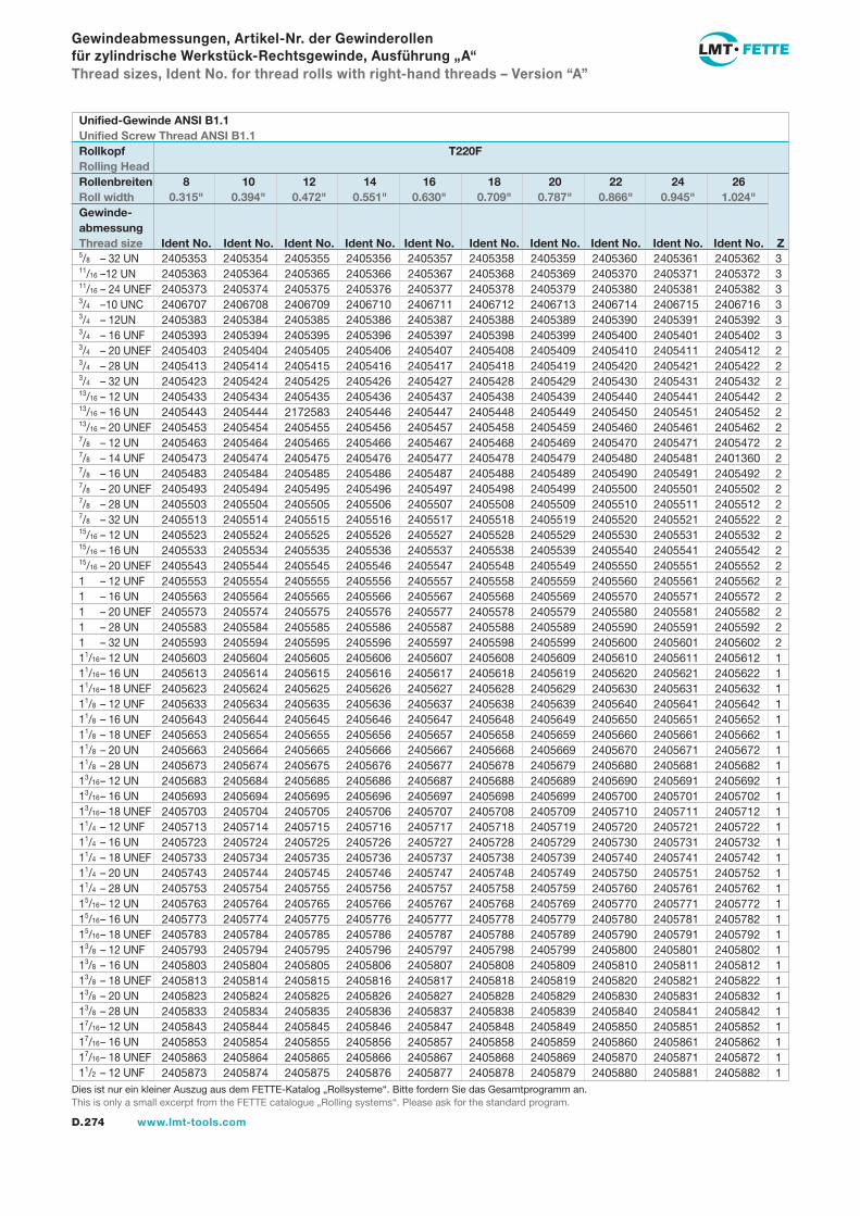
D.274 www.lmt-tools.com
5/8 – 32 UN11/16 –12 UN11/16 – 24 UNEF3/4 –10 UNC3/4 – 12UN3/4 – 16 UNF3/4 – 20 UNEF3/4 – 28 UN3/4 – 32 UN13/16 – 12 UN13/16 – 16 UN13/16 – 20 UNEF7/8 – 12 UN7/8 – 14 UNF7/8 – 16 UN7/8 – 20 UNEF7/8 – 28 UN7/8 – 32 UN15/16 – 12 UN15/16 – 16 UN15/16 – 20 UNEF1 – 12 UNF1 – 16 UN1 – 20 UNEF1 – 28 UN1 – 32 UN11/16 – 12 UN11/16 – 16 UN11/16 – 18 UNEF11/8 – 12 UNF11/8 – 16 UN11/8 – 18 UNEF11/8 – 20 UN11/8 – 28 UN13/16 – 12 UN13/16 – 16 UN13/16 – 18 UNEF11/4 – 12 UNF11/4 – 16 UN11/4 – 18 UNEF11/4 – 20 UN11/4 – 28 UN15/16 – 12 UN15/16 – 16 UN15/16 – 18 UNEF13/8 – 12 UNF13/8 – 16 UN13/8 – 18 UNEF13/8 – 20 UN13/8 – 28 UN17/16 – 12 UN17/16 – 16 UN17/16 – 18 UNEF11/2 – 12 UNF
2405353 2405354 2405355 2405356 2405357 2405358 2405359 2405360 2405361 2405362 3 2405363 2405364 2405365 2405366 2405367 2405368 2405369 2405370 2405371 2405372 3 2405373 2405374 2405375 2405376 2405377 2405378 2405379 2405380 2405381 2405382 3 2406707 2406708 2406709 2406710 2406711 2406712 2406713 2406714 2406715 2406716 3 2405383 2405384 2405385 2405386 2405387 2405388 2405389 2405390 2405391 2405392 3 2405393 2405394 2405395 2405396 2405397 2405398 2405399 2405400 2405401 2405402 3 2405403 2405404 2405405 2405406 2405407 2405408 2405409 2405410 2405411 2405412 2 2405413 2405414 2405415 2405416 2405417 2405418 2405419 2405420 2405421 2405422 2 2405423 2405424 2405425 2405426 2405427 2405428 2405429 2405430 2405431 2405432 2 2405433 2405434 2405435 2405436 2405437 2405438 2405439 2405440 2405441 2405442 2 2405443 2405444 2172583 2405446 2405447 2405448 2405449 2405450 2405451 2405452 2 2405453 2405454 2405455 2405456 2405457 2405458 2405459 2405460 2405461 2405462 2 2405463 2405464 2405465 2405466 2405467 2405468 2405469 2405470 2405471 2405472 2 2405473 2405474 2405475 2405476 2405477 2405478 2405479 2405480 2405481 2401360 2 2405483 2405484 2405485 2405486 2405487 2405488 2405489 2405490 2405491 2405492 2 2405493 2405494 2405495 2405496 2405497 2405498 2405499 2405500 2405501 2405502 2 2405503 2405504 2405505 2405506 2405507 2405508 2405509 2405510 2405511 2405512 2 2405513 2405514 2405515 2405516 2405517 2405518 2405519 2405520 2405521 2405522 2 2405523 2405524 2405525 2405526 2405527 2405528 2405529 2405530 2405531 2405532 2 2405533 2405534 2405535 2405536 2405537 2405538 2405539 2405540 2405541 2405542 2 2405543 2405544 2405545 2405546 2405547 2405548 2405549 2405550 2405551 2405552 2 2405553 2405554 2405555 2405556 2405557 2405558 2405559 2405560 2405561 2405562 2 2405563 2405564 2405565 2405566 2405567 2405568 2405569 2405570 2405571 2405572 2 2405573 2405574 2405575 2405576 2405577 2405578 2405579 2405580 2405581 2405582 2 2405583 2405584 2405585 2405586 2405587 2405588 2405589 2405590 2405591 2405592 2 2405593 2405594 2405595 2405596 2405597 2405598 2405599 2405600 2405601 2405602 2 2405603 2405604 2405605 2405606 2405607 2405608 2405609 2405610 2405611 2405612 1 2405613 2405614 2405615 2405616 2405617 2405618 2405619 2405620 2405621 2405622 1 2405623 2405624 2405625 2405626 2405627 2405628 2405629 2405630 2405631 2405632 1 2405633 2405634 2405635 2405636 2405637 2405638 2405639 2405640 2405641 2405642 1 2405643 2405644 2405645 2405646 2405647 2405648 2405649 2405650 2405651 2405652 1 2405653 2405654 2405655 2405656 2405657 2405658 2405659 2405660 2405661 2405662 1 2405663 2405664 2405665 2405666 2405667 2405668 2405669 2405670 2405671 2405672 1 2405673 2405674 2405675 2405676 2405677 2405678 2405679 2405680 2405681 2405682 1 2405683 2405684 2405685 2405686 2405687 2405688 2405689 2405690 2405691 2405692 1 2405693 2405694 2405695 2405696 2405697 2405698 2405699 2405700 2405701 2405702 1 2405703 2405704 2405705 2405706 2405707 2405708 2405709 2405710 2405711 2405712 1 2405713 2405714 2405715 2405716 2405717 2405718 2405719 2405720 2405721 2405722 1 2405723 2405724 2405725 2405726 2405727 2405728 2405729 2405730 2405731 2405732 1 2405733 2405734 2405735 2405736 2405737 2405738 2405739 2405740 2405741 2405742 1 2405743 2405744 2405745 2405746 2405747 2405748 2405749 2405750 2405751 2405752 1 2405753 2405754 2405755 2405756 2405757 2405758 2405759 2405760 2405761 2405762 1 2405763 2405764 2405765 2405766 2405767 2405768 2405769 2405770 2405771 2405772 1 2405773 2405774 2405775 2405776 2405777 2405778 2405779 2405780 2405781 2405782 1 2405783 2405784 2405785 2405786 2405787 2405788 2405789 2405790 2405791 2405792 1 2405793 2405794 2405795 2405796 2405797 2405798 2405799 2405800 2405801 2405802 1 2405803 2405804 2405805 2405806 2405807 2405808 2405809 2405810 2405811 2405812 1 2405813 2405814 2405815 2405816 2405817 2405818 2405819 2405820 2405821 2405822 1 2405823 2405824 2405825 2405826 2405827 2405828 2405829 2405830 2405831 2405832 1 2405833 2405834 2405835 2405836 2405837 2405838 2405839 2405840 2405841 2405842 1 2405843 2405844 2405845 2405846 2405847 2405848 2405849 2405850 2405851 2405852 1 2405853 2405854 2405855 2405856 2405857 2405858 2405859 2405860 2405861 2405862 1 2405863 2405864 2405865 2405866 2405867 2405868 2405869 2405870 2405871 2405872 1 2405873 2405874 2405875 2405876 2405877 2405878 2405879 2405880 2405881 2405882 1
Gewindeabmessungen, Artikel-Nr. der Gewinderollen für zylindrische Werkstück-Rechtsgewinde, Ausführung „A“Thread sizes, Ident No. for thread rolls with right-hand threads – Version “A”
Unified-Gewinde ANSI B1.1Unified Screw Thread ANSI B1.1Rollkopf T220FRolling HeadRollenbreiten 8 10 12 14 16 18 20 22 24 26Roll width 0.315" 0.394" 0.472" 0.551" 0.630" 0.709" 0.787" 0.866" 0.945" 1.024"Gewinde-abmessungThread size Ident No. Ident No. Ident No. Ident No. Ident No. Ident No. Ident No. Ident No. Ident No. Ident No. Z
Dies ist nur ein kleiner Auszug aus dem FETTE-Katalog „Rollsysteme“. Bitte fordern Sie das Gesamtprogramm an.This is only a small excerpt from the FETTE catalogue „Rolling systems“. Please ask for the standard program.
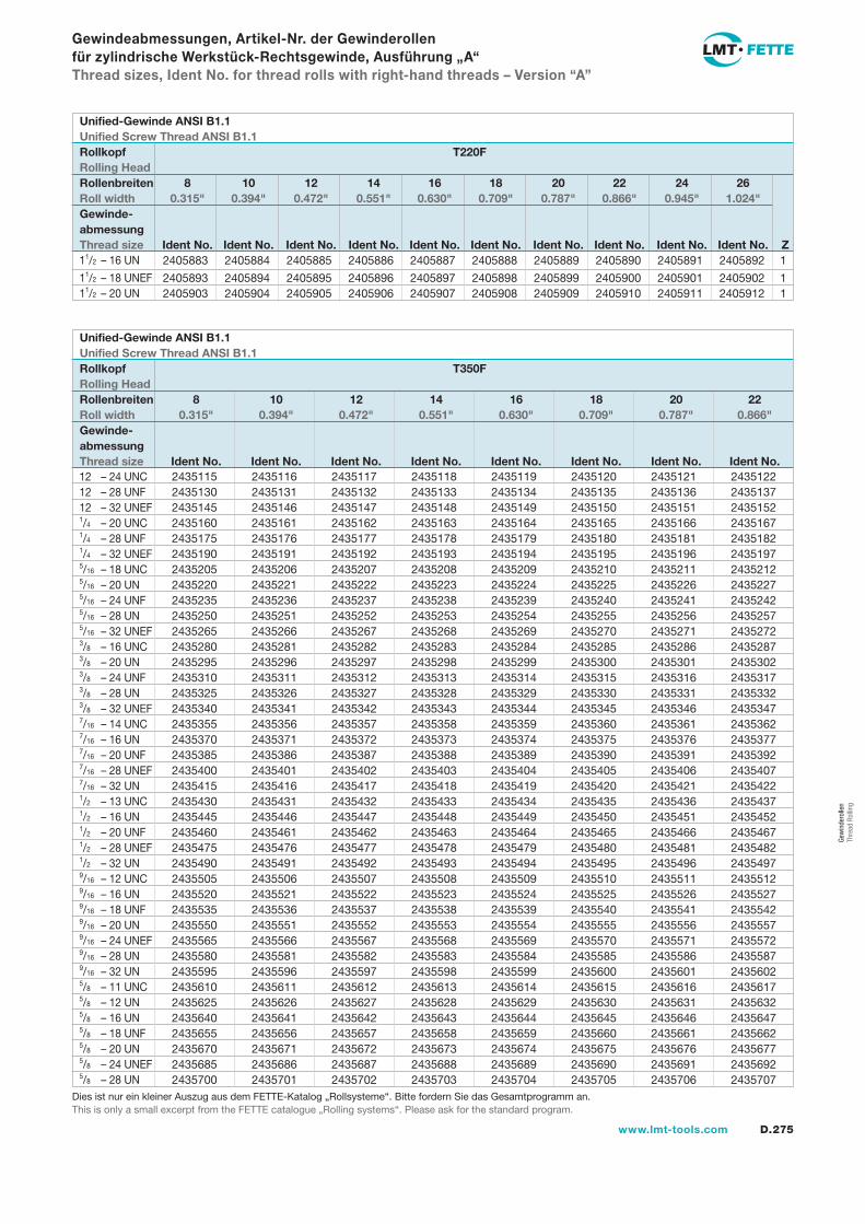
D.275www.lmt-tools.com
Gew
inde
rolle
n Th
read
Rol
ling
11/2 – 16 UN
11/2 – 18 UNEF11/2 – 20 UN
Gewindeabmessungen, Artikel-Nr. der Gewinderollen für zylindrische Werkstück-Rechtsgewinde, Ausführung „A“Thread sizes, Ident No. for thread rolls with right-hand threads – Version “A”
2405883 2405884 2405885 2405886 2405887 2405888 2405889 2405890 2405891 2405892 1
2405893 2405894 2405895 2405896 2405897 2405898 2405899 2405900 2405901 2405902 1 2405903 2405904 2405905 2405906 2405907 2405908 2405909 2405910 2405911 2405912 1
Unified-Gewinde ANSI B1.1Unified Screw Thread ANSI B1.1Rollkopf T220FRolling HeadRollenbreiten 8 10 12 14 16 18 20 22 24 26Roll width 0.315" 0.394" 0.472" 0.551" 0.630" 0.709" 0.787" 0.866" 0.945" 1.024"Gewinde-abmessungThread size Ident No. Ident No. Ident No. Ident No. Ident No. Ident No. Ident No. Ident No. Ident No. Ident No. Z
2435115 2435116 2435117 2435118 2435119 2435120 2435121 2435122 2435130 2435131 2435132 2435133 2435134 2435135 2435136 2435137 2435145 2435146 2435147 2435148 2435149 2435150 2435151 2435152 2435160 2435161 2435162 2435163 2435164 2435165 2435166 2435167 2435175 2435176 2435177 2435178 2435179 2435180 2435181 2435182 2435190 2435191 2435192 2435193 2435194 2435195 2435196 2435197 2435205 2435206 2435207 2435208 2435209 2435210 2435211 2435212 2435220 2435221 2435222 2435223 2435224 2435225 2435226 2435227 2435235 2435236 2435237 2435238 2435239 2435240 2435241 2435242 2435250 2435251 2435252 2435253 2435254 2435255 2435256 2435257 2435265 2435266 2435267 2435268 2435269 2435270 2435271 2435272 2435280 2435281 2435282 2435283 2435284 2435285 2435286 2435287 2435295 2435296 2435297 2435298 2435299 2435300 2435301 2435302 2435310 2435311 2435312 2435313 2435314 2435315 2435316 2435317 2435325 2435326 2435327 2435328 2435329 2435330 2435331 2435332 2435340 2435341 2435342 2435343 2435344 2435345 2435346 2435347 2435355 2435356 2435357 2435358 2435359 2435360 2435361 2435362 2435370 2435371 2435372 2435373 2435374 2435375 2435376 2435377 2435385 2435386 2435387 2435388 2435389 2435390 2435391 2435392 2435400 2435401 2435402 2435403 2435404 2435405 2435406 2435407 2435415 2435416 2435417 2435418 2435419 2435420 2435421 2435422 2435430 2435431 2435432 2435433 2435434 2435435 2435436 2435437 2435445 2435446 2435447 2435448 2435449 2435450 2435451 2435452 2435460 2435461 2435462 2435463 2435464 2435465 2435466 2435467 2435475 2435476 2435477 2435478 2435479 2435480 2435481 2435482 2435490 2435491 2435492 2435493 2435494 2435495 2435496 2435497 2435505 2435506 2435507 2435508 2435509 2435510 2435511 2435512 2435520 2435521 2435522 2435523 2435524 2435525 2435526 2435527 2435535 2435536 2435537 2435538 2435539 2435540 2435541 2435542 2435550 2435551 2435552 2435553 2435554 2435555 2435556 2435557 2435565 2435566 2435567 2435568 2435569 2435570 2435571 2435572 2435580 2435581 2435582 2435583 2435584 2435585 2435586 2435587 2435595 2435596 2435597 2435598 2435599 2435600 2435601 2435602 2435610 2435611 2435612 2435613 2435614 2435615 2435616 2435617 2435625 2435626 2435627 2435628 2435629 2435630 2435631 2435632 2435640 2435641 2435642 2435643 2435644 2435645 2435646 2435647 2435655 2435656 2435657 2435658 2435659 2435660 2435661 2435662 2435670 2435671 2435672 2435673 2435674 2435675 2435676 2435677 2435685 2435686 2435687 2435688 2435689 2435690 2435691 2435692 2435700 2435701 2435702 2435703 2435704 2435705 2435706 2435707
12 – 24 UNC12 – 28 UNF12 – 32 UNEF1/4 – 20 UNC1/4 – 28 UNF1/4 – 32 UNEF5/16 – 18 UNC5/16 – 20 UN5/16 – 24 UNF5/16 – 28 UN5/16 – 32 UNEF3/8 – 16 UNC3/8 – 20 UN3/8 – 24 UNF3/8 – 28 UN3/8 – 32 UNEF7/16 – 14 UNC7/16 – 16 UN7/16 – 20 UNF7/16 – 28 UNEF7/16 – 32 UN1/2 – 13 UNC1/2 – 16 UN1/2 – 20 UNF1/2 – 28 UNEF1/2 – 32 UN9/16 – 12 UNC9/16 – 16 UN9/16 – 18 UNF9/16 – 20 UN9/16 – 24 UNEF9/16 – 28 UN9/16 – 32 UN5/8 – 11 UNC5/8 – 12 UN5/8 – 16 UN5/8 – 18 UNF5/8 – 20 UN5/8 – 24 UNEF5/8 – 28 UN
Unified-Gewinde ANSI B1.1Unified Screw Thread ANSI B1.1Rollkopf T350FRolling HeadRollenbreiten 8 10 12 14 16 18 20 22Roll width 0.315" 0.394" 0.472" 0.551" 0.630" 0.709" 0.787" 0.866"Gewinde-abmessungThread size Ident No. Ident No. Ident No. Ident No. Ident No. Ident No. Ident No. Ident No.
Dies ist nur ein kleiner Auszug aus dem FETTE-Katalog „Rollsysteme“. Bitte fordern Sie das Gesamtprogramm an.This is only a small excerpt from the FETTE catalogue „Rolling systems“. Please ask for the standard program.
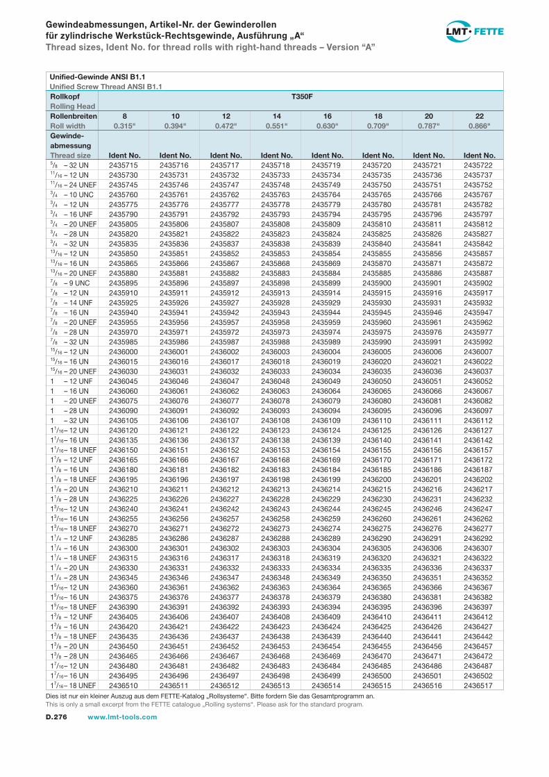
D.276 www.lmt-tools.com
2435715 2435716 2435717 2435718 2435719 2435720 2435721 2435722 2435730 2435731 2435732 2435733 2435734 2435735 2435736 2435737 2435745 2435746 2435747 2435748 2435749 2435750 2435751 2435752 2435760 2435761 2435762 2435763 2435764 2435765 2435766 2435767 2435775 2435776 2435777 2435778 2435779 2435780 2435781 2435782 2435790 2435791 2435792 2435793 2435794 2435795 2435796 2435797 2435805 2435806 2435807 2435808 2435809 2435810 2435811 2435812 2435820 2435821 2435822 2435823 2435824 2435825 2435826 2435827 2435835 2435836 2435837 2435838 2435839 2435840 2435841 2435842 2435850 2435851 2435852 2435853 2435854 2435855 2435856 2435857 2435865 2435866 2435867 2435868 2435869 2435870 2435871 2435872 2435880 2435881 2435882 2435883 2435884 2435885 2435886 2435887 2435895 2435896 2435897 2435898 2435899 2435900 2435901 2435902 2435910 2435911 2435912 2435913 2435914 2435915 2435916 2435917 2435925 2435926 2435927 2435928 2435929 2435930 2435931 2435932 2435940 2435941 2435942 2435943 2435944 2435945 2435946 2435947 2435955 2435956 2435957 2435958 2435959 2435960 2435961 2435962 2435970 2435971 2435972 2435973 2435974 2435975 2435976 2435977 2435985 2435986 2435987 2435988 2435989 2435990 2435991 2435992 2436000 2436001 2436002 2436003 2436004 2436005 2436006 2436007 2436015 2436016 2436017 2436018 2436019 2436020 2436021 2436022 2436030 2436031 2436032 2436033 2436034 2436035 2436036 2436037 2436045 2436046 2436047 2436048 2436049 2436050 2436051 2436052 2436060 2436061 2436062 2436063 2436064 2436065 2436066 2436067 2436075 2436076 2436077 2436078 2436079 2436080 2436081 2436082 2436090 2436091 2436092 2436093 2436094 2436095 2436096 2436097 2436105 2436106 2436107 2436108 2436109 2436110 2436111 2436112 2436120 2436121 2436122 2436123 2436124 2436125 2436126 2436127 2436135 2436136 2436137 2436138 2436139 2436140 2436141 2436142 2436150 2436151 2436152 2436153 2436154 2436155 2436156 2436157 2436165 2436166 2436167 2436168 2436169 2436170 2436171 2436172 2436180 2436181 2436182 2436183 2436184 2436185 2436186 2436187 2436195 2436196 2436197 2436198 2436199 2436200 2436201 2436202 2436210 2436211 2436212 2436213 2436214 2436215 2436216 2436217 2436225 2436226 2436227 2436228 2436229 2436230 2436231 2436232 2436240 2436241 2436242 2436243 2436244 2436245 2436246 2436247 2436255 2436256 2436257 2436258 2436259 2436260 2436261 2436262 2436270 2436271 2436272 2436273 2436274 2436275 2436276 2436277 2436285 2436286 2436287 2436288 2436289 2436290 2436291 2436292 2436300 2436301 2436302 2436303 2436304 2436305 2436306 2436307 2436315 2436316 2436317 2436318 2436319 2436320 2436321 2436322 2436330 2436331 2436332 2436333 2436334 2436335 2436336 2436337 2436345 2436346 2436347 2436348 2436349 2436350 2436351 2436352 2436360 2436361 2436362 2436363 2436364 2436365 2436366 2436367 2436375 2436376 2436377 2436378 2436379 2436380 2436381 2436382 2436390 2436391 2436392 2436393 2436394 2436395 2436396 2436397 2436405 2436406 2436407 2436408 2436409 2436410 2436411 2436412 2436420 2436421 2436422 2436423 2436424 2436425 2436426 2436427 2436435 2436436 2436437 2436438 2436439 2436440 2436441 2436442 2436450 2436451 2436452 2436453 2436454 2436455 2436456 2436457 2436465 2436466 2436467 2436468 2436469 2436470 2436471 2436472 2436480 2436481 2436482 2436483 2436484 2436485 2436486 2436487 2436495 2436496 2436497 2436498 2436499 2436500 2436501 2436502 2436510 2436511 2436512 2436513 2436514 2436515 2436516 2436517
Gewindeabmessungen, Artikel-Nr. der Gewinderollen für zylindrische Werkstück-Rechtsgewinde, Ausführung „A“Thread sizes, Ident No. for thread rolls with right-hand threads – Version “A”
5/8 – 32 UN11/16 – 12 UN11/16 – 24 UNEF3/4 – 10 UNC3/4 – 12 UN3/4 – 16 UNF3/4 – 20 UNEF3/4 – 28 UN3/4 – 32 UN13/16 – 12 UN13/16 – 16 UN13/16 – 20 UNEF7/8 – 9 UNC7/8 – 12 UN7/8 – 14 UNF7/8 – 16 UN7/8 – 20 UNEF7/8 – 28 UN7/8 – 32 UN15/16 – 12 UN15/16 – 16 UN15/16 – 20 UNEF1 – 12 UNF1 – 16 UN1 – 20 UNEF1 – 28 UN1 – 32 UN11/16 – 12 UN11/16 – 16 UN11/16 – 18 UNEF11/8 – 12 UNF11/8 – 16 UN11/8 – 18 UNEF11/8 – 20 UN11/8 – 28 UN13/16 – 12 UN13/16 – 16 UN13/16 – 18 UNEF11/4 – 12 UNF11/4 – 16 UN11/4 – 18 UNEF11/4 – 20 UN11/4 – 28 UN15/16 – 12 UN15/16 – 16 UN15/16 – 18 UNEF13/8 – 12 UNF13/8 – 16 UN13/8 – 18 UNEF13/8 – 20 UN13/8 – 28 UN17/16 – 12 UN17/16 – 16 UN17/16 – 18 UNEF
Unified-Gewinde ANSI B1.1Unified Screw Thread ANSI B1.1Rollkopf T350FRolling HeadRollenbreiten 8 10 12 14 16 18 20 22Roll width 0.315" 0.394" 0.472" 0.551" 0.630" 0.709" 0.787" 0.866"Gewinde-abmessungThread size Ident No. Ident No. Ident No. Ident No. Ident No. Ident No. Ident No. Ident No.
Dies ist nur ein kleiner Auszug aus dem FETTE-Katalog „Rollsysteme“. Bitte fordern Sie das Gesamtprogramm an.This is only a small excerpt from the FETTE catalogue „Rolling systems“. Please ask for the standard program.
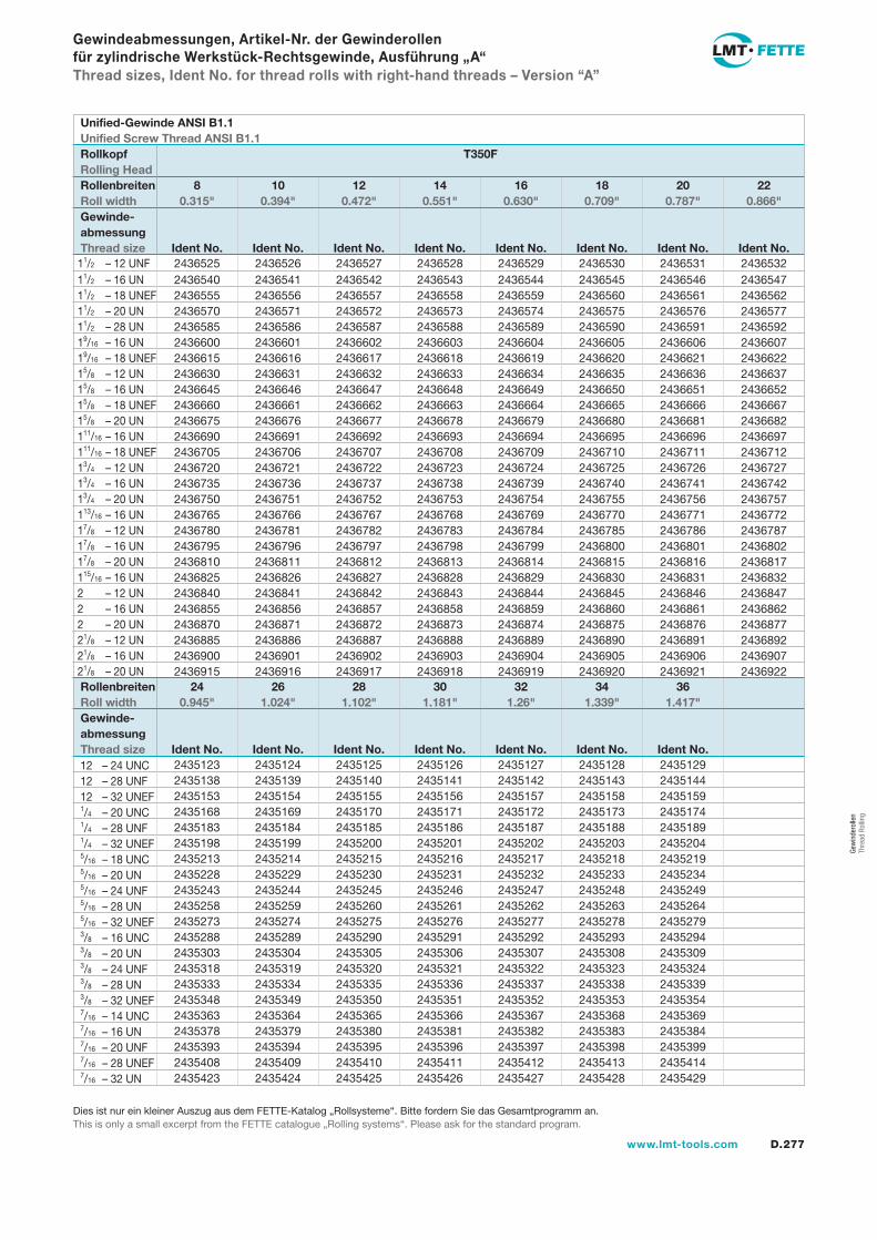
D.277www.lmt-tools.com
Gew
inde
rolle
n Th
read
Rol
ling
Gewindeabmessungen, Artikel-Nr. der Gewinderollen für zylindrische Werkstück-Rechtsgewinde, Ausführung „A“Thread sizes, Ident No. for thread rolls with right-hand threads – Version “A”
2436525 2436526 2436527 2436528 2436529 2436530 2436531 2436532 2436540 2436541 2436542 2436543 2436544 2436545 2436546 2436547 2436555 2436556 2436557 2436558 2436559 2436560 2436561 2436562 2436570 2436571 2436572 2436573 2436574 2436575 2436576 2436577 2436585 2436586 2436587 2436588 2436589 2436590 2436591 2436592 2436600 2436601 2436602 2436603 2436604 2436605 2436606 2436607 2436615 2436616 2436617 2436618 2436619 2436620 2436621 2436622 2436630 2436631 2436632 2436633 2436634 2436635 2436636 2436637 2436645 2436646 2436647 2436648 2436649 2436650 2436651 2436652 2436660 2436661 2436662 2436663 2436664 2436665 2436666 2436667 2436675 2436676 2436677 2436678 2436679 2436680 2436681 2436682 2436690 2436691 2436692 2436693 2436694 2436695 2436696 2436697 2436705 2436706 2436707 2436708 2436709 2436710 2436711 2436712 2436720 2436721 2436722 2436723 2436724 2436725 2436726 2436727 2436735 2436736 2436737 2436738 2436739 2436740 2436741 2436742 2436750 2436751 2436752 2436753 2436754 2436755 2436756 2436757 2436765 2436766 2436767 2436768 2436769 2436770 2436771 2436772 2436780 2436781 2436782 2436783 2436784 2436785 2436786 2436787 2436795 2436796 2436797 2436798 2436799 2436800 2436801 2436802 2436810 2436811 2436812 2436813 2436814 2436815 2436816 2436817 2436825 2436826 2436827 2436828 2436829 2436830 2436831 2436832 2436840 2436841 2436842 2436843 2436844 2436845 2436846 2436847 2436855 2436856 2436857 2436858 2436859 2436860 2436861 2436862 2436870 2436871 2436872 2436873 2436874 2436875 2436876 2436877 2436885 2436886 2436887 2436888 2436889 2436890 2436891 2436892 2436900 2436901 2436902 2436903 2436904 2436905 2436906 2436907 2436915 2436916 2436917 2436918 2436919 2436920 2436921 2436922
2435123 2435124 2435125 2435126 2435127 2435128 2435129 2435138 2435139 2435140 2435141 2435142 2435143 2435144 2435153 2435154 2435155 2435156 2435157 2435158 2435159 2435168 2435169 2435170 2435171 2435172 2435173 2435174 2435183 2435184 2435185 2435186 2435187 2435188 2435189 2435198 2435199 2435200 2435201 2435202 2435203 2435204 2435213 2435214 2435215 2435216 2435217 2435218 2435219 2435228 2435229 2435230 2435231 2435232 2435233 2435234 2435243 2435244 2435245 2435246 2435247 2435248 2435249 2435258 2435259 2435260 2435261 2435262 2435263 2435264 2435273 2435274 2435275 2435276 2435277 2435278 2435279 2435288 2435289 2435290 2435291 2435292 2435293 2435294 2435303 2435304 2435305 2435306 2435307 2435308 2435309 2435318 2435319 2435320 2435321 2435322 2435323 2435324 2435333 2435334 2435335 2435336 2435337 2435338 2435339 2435348 2435349 2435350 2435351 2435352 2435353 2435354 2435363 2435364 2435365 2435366 2435367 2435368 2435369 2435378 2435379 2435380 2435381 2435382 2435383 2435384 2435393 2435394 2435395 2435396 2435397 2435398 2435399 2435408 2435409 2435410 2435411 2435412 2435413 2435414 2435423 2435424 2435425 2435426 2435427 2435428 2435429
11/2 – 12 UNF11/2 – 16 UN11/2 – 18 UNEF11/2 – 20 UN11/2 – 28 UN19/16 – 16 UN19/16 – 18 UNEF15/8 – 12 UN15/8 – 16 UN15/8 – 18 UNEF15/8 – 20 UN111/16 – 16 UN111/16 – 18 UNEF13/4 – 12 UN13/4 – 16 UN13/4 – 20 UN113/16 – 16 UN17/8 – 12 UN17/8 – 16 UN17/8 – 20 UN115/16 – 16 UN2 – 12 UN2 – 16 UN2 – 20 UN21/8 – 12 UN21/8 – 16 UN21/8 – 20 UN
12 – 24 UNC12 – 28 UNF12 – 32 UNEF1/4 – 20 UNC1/4 – 28 UNF1/4 – 32 UNEF5/16 – 18 UNC5/16 – 20 UN5/16 – 24 UNF5/16 – 28 UN5/16 – 32 UNEF3/8 – 16 UNC3/8 – 20 UN3/8 – 24 UNF3/8 – 28 UN3/8 – 32 UNEF7/16 – 14 UNC7/16 – 16 UN7/16 – 20 UNF7/16 – 28 UNEF7/16 – 32 UN
Rollenbreiten 8 10 12 14 16 18 20 22 Roll width 0.315" 0.394" 0.472" 0.551" 0.630" 0.709" 0.787" 0.866" Gewinde- abmessung Thread size Ident No. Ident No. Ident No. Ident No. Ident No. Ident No. Ident No. Ident No.
Rollenbreiten 24 26 28 30 32 34 36 Roll width 0.945" 1.024" 1.102" 1.181" 1.26" 1.339" 1.417" Gewinde- abmessung Thread size Ident No. Ident No. Ident No. Ident No. Ident No. Ident No. Ident No.
Unified-Gewinde ANSI B1.1 Unified Screw Thread ANSI B1.1 Rollkopf T350F Rolling Head
Dies ist nur ein kleiner Auszug aus dem FETTE-Katalog „Rollsysteme“. Bitte fordern Sie das Gesamtprogramm an.This is only a small excerpt from the FETTE catalogue „Rolling systems“. Please ask for the standard program.
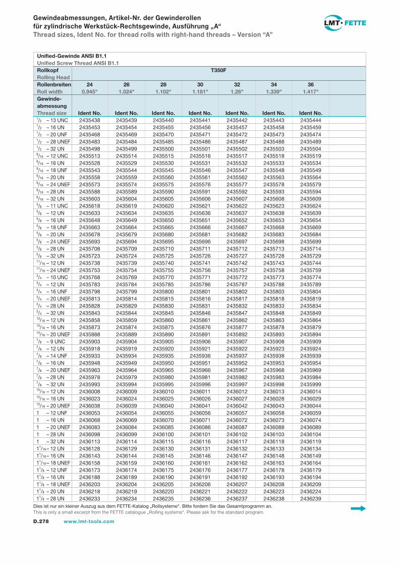
D.278 www.lmt-tools.com
Gewindeabmessungen, Artikel-Nr. der Gewinderollen für zylindrische Werkstück-Rechtsgewinde, Ausführung „A“Thread sizes, Ident No. for thread rolls with right-hand threads – Version “A”
2435438 2435439 2435440 2435441 2435442 2435443 2435444 2435453 2435454 2435455 2435456 2435457 2435458 2435459 2435468 2435469 2435470 2435471 2435472 2435473 2435474 2435483 2435484 2435485 2435486 2435487 2435488 2435489 2435498 2435499 2435500 2435501 2435502 2435503 2435504 2435513 2435514 2435515 2435516 2435517 2435518 2435519 2435528 2435529 2435530 2435531 2435532 2435533 2435534 2435543 2435544 2435545 2435546 2435547 2435548 2435549 2435558 2435559 2435560 2435561 2435562 2435563 2435564 2435573 2435574 2435575 2435576 2435577 2435578 2435579 2435588 2435589 2435590 2435591 2435592 2435593 2435594 2435603 2435604 2435605 2435606 2435607 2435608 2435609 2435618 2435619 2435620 2435621 2435622 2435623 2435624 2435633 2435634 2435635 2435636 2435637 2435638 2435639 2435648 2435649 2435650 2435651 2435652 2435653 2435654 2435663 2435664 2435665 2435666 2435667 2435668 2435669 2435678 2435679 2435680 2435681 2435682 2435683 2435684 2435693 2435694 2435695 2435696 2435697 2435698 2435699 2435708 2435709 2435710 2435711 2435712 2435713 2435714 2435723 2435724 2435725 2435726 2435727 2435728 2435729 2435738 2435739 2435740 2435741 2435742 2435743 2435744 2435753 2435754 2435755 2435756 2435757 2435758 2435759 2435768 2435769 2435770 2435771 2435772 2435773 2435774 2435783 2435784 2435785 2435786 2435787 2435788 2435789 2435798 2435799 2435800 2435801 2435802 2435803 2435804 2435813 2435814 2435815 2435816 2435817 2435818 2435819 2435828 2435829 2435830 2435831 2435832 2435833 2435834 2435843 2435844 2435845 2435846 2435847 2435848 2435849 2435858 2435859 2435860 2435861 2435862 2435863 2435864 2435873 2435874 2435875 2435876 2435877 2435878 2435879 2435888 2435889 2435890 2435891 2435892 2435893 2435894 2435903 2435904 2435905 2435906 2435907 2435908 2435909 2435918 2435919 2435920 2435921 2435922 2435923 2435924 2435933 2435934 2435935 2435936 2435937 2435938 2435939 2435948 2435949 2435950 2435951 2435952 2435953 2435954 2435963 2435964 2435965 2435966 2435967 2435968 2435969 2435978 2435979 2435980 2435981 2435982 2435983 2435984 2435993 2435994 2435995 2435996 2435997 2435998 2435999 2436008 2436009 2436010 2436011 2436012 2436013 2436014 2436023 2436024 2436025 2436026 2436027 2436028 2436029 2436038 2436039 2436040 2436041 2436042 2436043 2436044 2436053 2436054 2436055 2436056 2436057 2436058 2436059 2436068 2436069 2436070 2436071 2436072 2436073 2436074 2436083 2436084 2436085 2436086 2436087 2436088 2436089 2436098 2436099 2436100 2436101 2436102 2436103 2436104 2436113 2436114 2436115 2436116 2436117 2436118 2436119 2436128 2436129 2436130 2436131 2436132 2436133 2436134 2436143 2436144 2436145 2436146 2436147 2436148 2436149 2436158 2436159 2436160 2436161 2436162 2436163 2436164 2436173 2436174 2436175 2436176 2436177 2436178 2436179 2436188 2436189 2436190 2436191 2436192 2436193 2436194 2436203 2436204 2436205 2436206 2436207 2436208 2436209 2436218 2436219 2436220 2436221 2436222 2436223 2436224 2436233 2436234 2436235 2436236 2436237 2436238 2436239
1/2 – 13 UNC1/2 – 16 UN1/2 – 20 UNF1/2 – 28 UNEF1/2 – 32 UN9/16 – 12 UNC9/16 – 16 UN9/16 – 18 UNF9/16 – 20 UN9/16 – 24 UNEF9/16 – 28 UN9/16 – 32 UN5/8 – 11 UNC5/8 – 12 UN5/8 – 16 UN5/8 – 18 UNF5/8 – 20 UN5/8 – 24 UNEF5/8 – 28 UN5/8 – 32 UN11/16 – 12 UN11/16 – 24 UNEF3/4 – 10 UNC3/4 – 12 UN3/4 – 16 UNF3/4 – 20 UNEF3/4 – 28 UN3/4 – 32 UN13/16 – 12 UN13/16 – 16 UN13/16 – 20 UNEF7/8 – 9 UNC7/8 – 12 UN7/8 – 14 UNF7/8 – 16 UN7/8 – 20 UNEF7/8 – 28 UN7/8 – 32 UN15/16 – 12 UN15/16 – 16 UN15/16 – 20 UNEF1 – 12 UNF1 – 16 UN1 – 20 UNEF1 – 28 UN1 – 32 UN11/16 – 12 UN11/16 – 16 UN11/16 – 18 UNEF11/8 – 12 UNF11/8 – 16 UN11/8 – 18 UNEF11/8 – 20 UN11/8 – 28 UN
Unified-Gewinde ANSI B1.1Unified Screw Thread ANSI B1.1Rollkopf T350FRolling HeadRollenbreiten 24 26 28 30 32 34 36Roll width 0.945" 1.024" 1.102" 1.181" 1.26" 1.339" 1.417"Gewinde-abmessungThread size Ident No. Ident No. Ident No. Ident No. Ident No. Ident No. Ident No.
Dies ist nur ein kleiner Auszug aus dem FETTE-Katalog „Rollsysteme“. Bitte fordern Sie das Gesamtprogramm an.This is only a small excerpt from the FETTE catalogue „Rolling systems“. Please ask for the standard program.
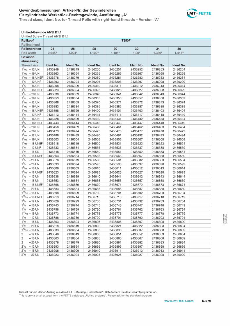
D.279www.lmt-tools.com
Gew
inde
rolle
n Th
read
Rol
ling
Gewindeabmessungen, Artikel-Nr. der Gewinderollen für zylindrische Werkstück-Rechtsgewinde, Ausführung „A“Thread sizes, Ident No. for Thread Rolls with right-hand threads – Version “A”
2436248 2436249 2436250 2436251 2436252 2436253 2436254 2436263 2436264 2436265 2436266 2436267 2436268 2436269 2436278 2436279 2436280 2436281 2436282 2436283 2436284 2436293 2436294 2436295 2436296 2436297 2436298 2436299 2436308 2436309 2436310 2436311 2436312 2436313 2436314 2436323 2436324 2436325 2436326 2436327 2436328 2436329 2436338 2436339 2436340 2436341 2436342 2436343 2436344 2436353 2436354 2436355 2436356 2436357 2436358 2436359 2436368 2436369 2436370 2436371 2436372 2436373 2436374 2436383 2436384 2436385 2436386 2436387 2436388 2436389 2436398 2436399 2436400 2436401 2436402 2436403 2436404 2436413 2436414 2436415 2436416 2436417 2436418 2436419 2436428 2436429 2436430 2436431 2436432 2436433 2436434 2436443 2436444 2436445 2436446 2436447 2436448 2436449 2436458 2436459 2436460 2436461 2436462 2436463 2436464 2436473 2436474 2436475 2436476 2436477 2436478 2436479 2436488 2436489 2436490 2436491 2436492 2436493 2436494 2436503 2436504 2436505 2436506 2436507 2436508 2436509 2436518 2436519 2436520 2436521 2436522 2436523 2436524 2436533 2436534 2436535 2436536 2436537 2436538 2436539 2436548 2436549 2436550 2436551 2436552 2436553 2436554 2436563 2436564 2436565 2436566 2436567 2436568 2436569 2436578 2436579 2436580 2436581 2436582 2436583 2436584 2436593 2436594 2436595 2436596 2436597 2436598 2436599 2436608 2436609 2436610 2436611 2436612 2436613 2436614 2436623 2436624 2436625 2436626 2436627 2436628 2436629 2436638 2436639 2436640 2436641 2436642 2436643 2436644 2436653 2436654 2436655 2436656 2436657 2436658 2436659 2436668 2436669 2436670 2436671 2436672 2436673 2436674 2436683 2436684 2436685 2436686 2436687 2436688 2436689 2436698 2436699 2436700 2436701 2436702 2436703 2436704 2436713 2436714 2436715 2436716 2436717 2436718 2436719 2436728 2436729 2436730 2436731 2436732 2436733 2436734 2436743 2436744 2436745 2436746 2436747 2436748 2436749 2436758 2436759 2436760 2436761 2436762 2436763 2436764 2436773 2436774 2436775 2436776 2436777 2436778 2436779 2436788 2436789 2436790 2436791 2436792 2436793 2436794 2436803 2436804 2436805 2436806 2436807 2436808 2436809 2436818 2436819 2436820 2436821 2436822 2436823 2436824 2436833 2436834 2436835 2436836 2436837 2436838 2436839 2436848 2436849 2436850 2436851 2436852 2436853 2436854 2436863 2436864 2436865 2436866 2436867 2436868 2436869 2436878 2436879 2436880 2436881 2436882 2436883 2436884 2436893 2436894 2436895 2436896 2436897 2436898 2436899 2436908 2436909 2436910 2436911 2436912 2436913 2436914 2436923 2436924 2436925 2436926 2436927 2436928 2436929
13/16 – 12 UN13/16 – 16 UN13/16 – 18 UNEF11/4 – 12 UNF11/4 – 16 UN11/4 – 18 UNEF11/4 – 20 UN11/4 – 28 UN15/16 – 12 UN15/16 – 16 UN15/16 – 18 UNEF13/8 – 12 UNF13/8 – 16 UN13/8 – 18 UNEF13/8 – 20 UN13/8 – 28 UN17/16 – 12 UN17/16 – 16 UN17/16 – 18 UNEF11/2 – 12 UNF11/2 – 16 UN11/2 – 18 UNEF11/2 – 20 UN11/2 – 28 UN19/16 – 16 UN19/16 – 18 UNEF15/8 – 12 UN15/8 – 16 UN15/8 – 18 UNEF15/8 – 20 UN111/16 – 16 UN111/16 – 18 UNEF13/4 – 12 UN13/4 – 16 UN13/4 – 20 UN113/16 – 16 UN17/8 – 12 UN17/8 – 16 UN17/8 – 20 UN115/16 – 16 UN2 – 12 UN2 – 16 UN2 – 20 UN21/8 – 12 UN21/8 – 16 UN21/8 – 20 UN
Unified-Gewinde ANSI B1.1Unified Screw Thread ANSI B1.1Rollkopf T350FRolling headRollenbreiten 24 26 28 30 32 34 36Roll width 0.945" 1.024" 1.102" 1.181" 1.26" 1.339" 1.417"Gewinde-abmessungThread size Ident No. Ident No. Ident No. Ident No. Ident No. Ident No. Ident No.
Dies ist nur ein kleiner Auszug aus dem FETTE-Katalog „Rollsysteme“. Bitte fordern Sie das Gesamtprogramm an.This is only a small excerpt from the FETTE catalogue „Rolling systems“. Please ask for the standard program.
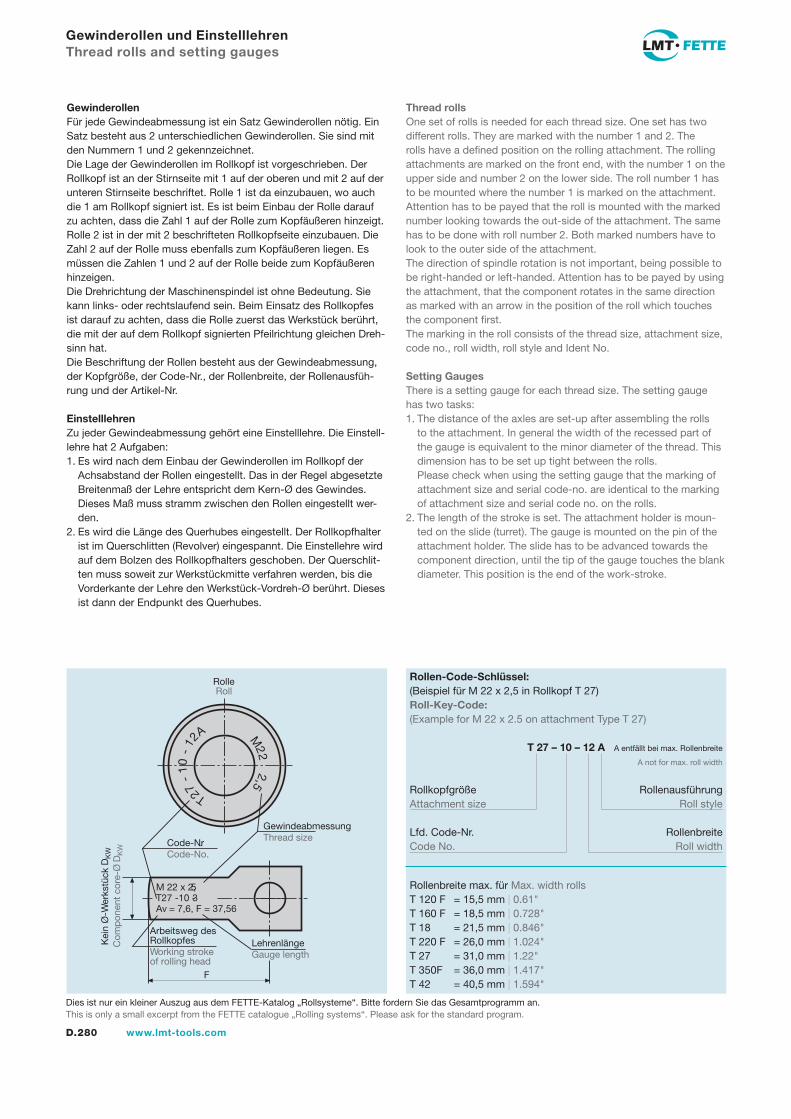
D.280 www.lmt-tools.com
Gewinderollen und EinstelllehrenThread rolls and setting gauges
GewinderollenFür jede Gewindeabmessung ist ein Satz Gewinderollen nötig. Ein Satz besteht aus 2 unterschiedlichen Gewinderollen. Sie sind mit den Nummern 1 und 2 gekennzeichnet.Die Lage der Gewinderollen im Rollkopf ist vorgeschrieben. Der Rollkopf ist an der Stirnseite mit 1 auf der oberen und mit 2 auf der unteren Stirnseite beschriftet. Rolle 1 ist da einzubauen, wo auch die 1 am Rollkopf signiert ist. Es ist beim Einbau der Rolle darauf zu achten, dass die Zahl 1 auf der Rolle zum Kopfäußeren hinzeigt. Rolle 2 ist in der mit 2 beschrifteten Rollkopfseite einzubauen. Die Zahl 2 auf der Rolle muss ebenfalls zum Kopfäußeren liegen. Es müssen die Zahlen 1 und 2 auf der Rolle beide zum Kopfäußeren hinzeigen.Die Drehrichtung der Maschinenspindel ist ohne Bedeutung. Sie kann links- oder rechtslaufend sein. Beim Einsatz des Rollkopfes ist darauf zu achten, dass die Rolle zuerst das Werkstück berührt, die mit der auf dem Rollkopf signierten Pfeilrichtung gleichen Dreh-sinn hat.Die Beschriftung der Rollen besteht aus der Gewindeabmessung, der Kopfgröße, der Code-Nr., der Rollenbreite, der Rollenausfüh-rung und der Artikel-Nr.
EinstelllehrenZu jeder Gewindeabmessung gehört eine Einstelllehre. Die Einstell-lehre hat 2 Aufgaben: 1. Es wird nach dem Einbau der Gewinderollen im Rollkopf der
Achsabstand der Rollen eingestellt. Das in der Regel abgesetzte Breitenmaß der Lehre entspricht dem Kern-Ø des Gewindes. Dieses Maß muss stramm zwischen den Rollen eingestellt wer-den.
2. Es wird die Länge des Querhubes eingestellt. Der Rollkopfhalter ist im Querschlitten (Revolver) eingespannt. Die Einstellehre wird auf dem Bolzen des Rollkopfhalters geschoben. Der Querschlit-ten muss soweit zur Werkstückmitte verfahren werden, bis die Vorderkante der Lehre den Werkstück-Vordreh-Ø berührt. Dieses ist dann der Endpunkt des Querhubes.
Thread rollsOne set of rolls is needed for each thread size. One set has two different rolls. They are marked with the number 1 and 2. The rolls have a defined position on the rolling attachment. The rolling attachments are marked on the front end, with the number 1 on the upper side and number 2 on the lower side. The roll number 1 has to be mounted where the number 1 is marked on the attachment. Attention has to be payed that the roll is mounted with the marked number looking towards the out-side of the attachment. The same has to be done with roll number 2. Both marked numbers have to look to the outer side of the attachment.The direction of spindle rotation is not important, being possible to be right-handed or left-handed. Attention has to be payed by using the attachment, that the component rotates in the same direction as marked with an arrow in the position of the roll which touches the component first.The marking in the roll consists of the thread size, attachment size, code no., roll width, roll style and Ident No.
Setting GaugesThere is a setting gauge for each thread size. The setting gauge has two tasks: 1. The distance of the axles are set-up after assembling the rolls
to the attachment. In general the width of the recessed part of the gauge is equivalent to the minor diameter of the thread. This dimension has to be set up tight between the rolls.
Please check when using the setting gauge that the marking of attachment size and serial code-no. are identical to the marking of attachment size and serial code no. on the rolls.
2. The length of the stroke is set. The attachment holder is moun-ted on the slide (turret). The gauge is mounted on the pin of the attachment holder. The slide has to be advanced towards the component direction, until the tip of the gauge touches the blank diameter. This position is the end of the work-stroke.
Rollenbreite max. für Max. width rollsT 120 F = 15,5 mm | 0.61"T 160 F = 18,5 mm | 0.728"T 18 = 21,5 mm | 0.846"T 220 F = 26,0 mm | 1.024"T 27 = 31,0 mm | 1.22"T 350F = 36,0 mm | 1.417"T 42 = 40,5 mm | 1.594"
Rollen-Code-Schlüssel:(Beispiel für M 22 x 2,5 in Rollkopf T 27)Roll-Key-Code:(Example for M 22 x 2.5 on attachment Type T 27)
T 27 – 10 – 12 A A entfällt bei max. Rollenbreite
A not for max. roll width
Rollkopfgröße RollenausführungAttachment size Roll style
Lfd. Code-Nr. Rollenbreite Code No. Roll width
M 22 x 2,5T27 -10 - 3Av = 7,6, F = 37,56
T27-
10
-12
A M22
2,5
Arbeitsweg desRollkopfesWorking strokeof rolling head
LehrenlängeGauge length
GewindeabmessungThread sizeCode-Nr.
Code-No.
Kei
n Ø
-Wer
kstü
ck D
KW
Com
pon
ent
core
-Ø D
KW
RolleRoll
F
Dies ist nur ein kleiner Auszug aus dem FETTE-Katalog „Rollsysteme“. Bitte fordern Sie das Gesamtprogramm an.This is only a small excerpt from the FETTE catalogue „Rolling systems“. Please ask for the standard program.
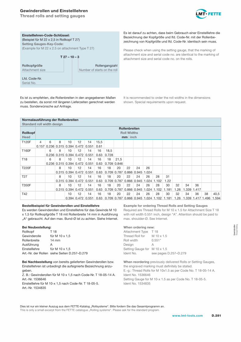
D.281www.lmt-tools.com
Gew
inde
rolle
n Th
read
Rol
ling
T120F 4 6 8 10 12 14 15,5 0.157 0.236 0.315 0.394 0.472 0.551 0.61 T160F 6 8 10 12 14 16 18,5 0.236 0.315 0.394 0.472 0.551 0.63 0.728T18 6 8 10 12 14 16 18 21,5 0.236 0.315 0.394 0.472 0.551 0.63 0.709 0.846T220F 8 10 12 14 16 18 20 22 24 26 0.315 0.394 0.472 0.551 0.63 0.709 0.787 0.866 0.945 1.024T27 8 10 12 14 16 18 20 22 24 26 28 31 0.315 0.394 0.472 0.551 0.63 0.709 0.787 0.866 0.945 1.024 1.102 1.22T350F 8 10 12 14 16 18 20 22 24 26 28 30 32 34 36 0.315 0.394 0.472 0.551 0.63 0.709 0.787 0.866 0.945 1.024 1.102 1.181 1.26 1.339 1.417T42 10 12 14 16 18 20 22 24 26 28 30 32 34 36 38 40,5 0.394 0.472 0.551 0.63 0.709 0.787 0.866 0.945 1.024 1.102 1.181 1.26 1.339 1.417 1.496 1.594
Gewinderollen und EinstelllehrenThread rolls and setting gauges
Normalausführung der RollenbreitenStandard roll width design RollenbreitenRollkopf Roll WidthsHead mm | inch
Es ist zu empfehlen, die Rollenbreiten in den angegebenen Maßen zu bestellen, da sonst mit längeren Lieferzeiten gerechnet werden muss. Sonderwünsche auf Anfrage.
It is recommended to order the roll widths in the dimensions shown. Special requirements upon request.
Bestellbeispiel für Gewinderollen und EinstelllehreEs werden Gewinderollen und Einstelllehre für das Gewinde M 10 x 1,5 für Rollkopfgröße T 18 mit Rollenbreite 14 mm in Ausführung „A“ gebraucht. Auf den max. Bund-Ø ist zu achten. Siehe Internet.
Bei Neubestellung:Rollkopf T 18Gewinderolle für M 10 x 1,5Rollenbreite 14 mmAusführung AEinstelllehre für M 10 x 1,5Art.-Nr. der Rollen siehe Seiten D.257–D.279
Bei Nachbestellung von bereits gelieferten Gewinderollen bzw. Einstelllehren ist unbedingt die aufsignierte Bezeichnung anzu-geben.Z. B.: Gewinderollen für M 10 x 1,5 nach Code-Nr. T 18-05-14 A. Art.-Nr. 1536646Einstelllehre für M 10-x 1,5 nach Code-Nr. T 18-05-5. Art.-Nr. 1534835
Example for ordering Thread Rolls and Setting GaugesRequired are Thread Rolls for M 10 x 1.5 for Attachment Size T 18 with roll width 0.551 inch, design “A”. Attention should be paid to max. shoulder-Ø. See Internet.
When ordering new:Attachment Type T 18Thread Roll for M 10 x 1.5Roll width 0.551"Design ASetting Gauge for M 10 x 1.5Ident No. see pages D.257–D.279
When reordering previously delivered Rolls or Setting Gauges, the engraved marking must definitely be stated.E.-g.: Thread Rolls for M 10x1.5 as per Code No. T 18-05-14 A. Ident No. 1536646Setting Gauge for M 10-x 1.5 as per Code No. T 18-05-5. Ident No. 1534835
Es ist darauf zu achten, dass beim Gebrauch einer Einstelllehre die Bezeichnung der Kopfgröße und lfd. Code-Nr. mit der Rollenbe-zeichnung von Kopfgröße und lfd. Code-Nr. identisch sein muss.
Einstelllehren-Code-Schlüssel:(Beispiel für M 22 x 2,5 in Rollkopf T 27)Setting Gauges-Key-Code:(Example for M 22 x 2.5 on attachment Type T 27)
T 27 – 10 – 3
Rollkopfgröße RollengangzahlAttachment size Number of starts on the roll
Lfd. Code-Nr.Serial No.
Please check when using the setting gauge, that the marking of attachment size and serial code no. are identical to the marking of attachment size and serial code no. on the rolls.
Dies ist nur ein kleiner Auszug aus dem FETTE-Katalog „Rollsysteme“. Bitte fordern Sie das Gesamtprogramm an.This is only a small excerpt from the FETTE catalogue „Rolling systems“. Please ask for the standard program.
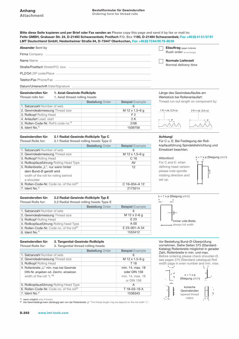
D.282 www.lmt-tools.com
Bestellung Order Beispiel Example1. Satzanzahl Number of sets 62. Gewindeabmessung Thread size M 12 x 1,5–6 g3. Rollkopf Rolling Head T 184. Rollenbreite „L“ min. max bei Gewinde min. 14, max. 185. DIN-Nr. angeben od. Zeichn. einsetzen oder DIN 1585. width of the roll “L”2) min. 14, max. 185. or DIN 1585. Rollkopfausführung Rolling Head Type A6. Rollen-Code-Nr. Code no. of the roll1) T 18–03–16 A7. Ident No.1) 1536343
Bestellung Order Beispiel Example1. Satzanzahl Number of sets 62. Gewindeabmessung Thread size M 12 x 2–6 g3. Rollkopf Rolling Head E 234. Rollkopfausführung Rolling head Type A 005. Rollen-Code-Nr. Code no. of the roll1) E 23–001–A 346. Ident No.1) 1553412
Gewinderollen für: 1. Axial-Gewinde-RollköpfeThread rolls for: 1. Axial thread rolling heads
Bestellformular für GewinderollenOrdering form for thread rolls
AnhangAttachment
Länge des Gewindeauflaufes am Werkstück bei Rollenanlaufart:Thread run-out length on component by:
x x
A
x x
AV
P
1 K = ca. 2,3 x p
P
2 K = ca. 3,3 x p
Achtung!Für C u. E: Bei Festlegung der Roll-kopfausführung Spindeldrehrichtung und Einsatzart beachten.
Attention!For C and E: when defining head version please note spindle rotating direction and set up.
Vor Bestellung Bund-Ø-Überprüfung vornehmen. Siehe Seiten 375 (Standard-Katalog) Rollenbreite möglichst in gerader Zahl, Rollenbreite in min. und max. Before ordering please check shoulder-Ø, see pages 375 (Standard catalogue) Roll width page in even number and min. max.
A
X X
L
B
X X
L
x = 1 x p(Steigung pitch)
konische Gewinderollentapered thread
rollers
Bitte diese Seite kopieren und per Brief oder Fax senden an Please copy this page and send it by fax or mail to:Fette GMBH, Grabauer Str. 24, D-21493 Schwarzenbek; Postfach P.O. Box 1180, D-21484 Schwarzenbek; Fax +49 (0) 41 51/37 97LMT Deutschland GmbH, Heidenheimer Straße 84, D-73447 Oberkochen, Fax +49 (0) 73 64/95 79-80 00
Absender Sent by
Firma Company
Name Name
Straße/Postfach Street/P.O. box
PLZ/Ort ZIP code/Place
Telefon/Fax Phone/Fax
Datum/Unterschrift Date/Signature
Eilauftrag (gegen Aufpreis)
Rush order (at surcharge)
Normale LieferzeitNormal delivery time
Gewinderollen für: 2.2 Radial-Gewinde-Rollköpfe Typ EThread Rolls for: 2.2 Radial thread rolling heads Type E
Gewinderollen für: 2.1 Radial-Gewinde-Rollköpfe Typ CThread Rolls for: 2.1 Radial thread rolling heads Type C
Gewinderollen für: 3. Tangential-Gewinde-RollköpfeThread Rolls for: 3. Tangential thread rolling heads
1) wenn möglich only if known2) Die Gewindelänge kann abhängig sein von der Rollenbreite „L“ The thread length may be depend on the roll width “L”.
Bestellung Order Beispiel Example1. Satzanzahl Number of sets 62. Gewindeabmessung Thread size M 12 x 1,5–6 g3. Rollkopf Rolling Head F 24. Anlaufart Lead, start 2 K5. Rollen-Code-Nr. Roll’s code no.1) 2/066. Ident No.1) 1509756
Bestellung Order Beispiel Example1. Satzanzahl Number of sets 62. Gewindeabmessung Thread size M 12 x 1,5–6 g3. Rollkopf Rolling Head C 164. Rollkopfausführung Rolling Head Type AV5. Rollenbreite „L“, nur wenn hinter 125. dem Bund-Ø gerollt wird5. width of the roll for rolling behind5. a shoulder6. Rollen-Code-Nr. Code no. of the roll1) C 16–034–A 127. Ident No.1) 2173514
x = 1 x p (Steigung pitch)
x = 1 x p (Steigung pitch)
immer volle Breite always full width
D.283www.lmt-tools.com
NotizenNotes
Gew
inde
rolle
n Th
read
Rol
ling


![[PPT]No Slide Title - Wikispacesptec107.wikispaces.com/file/view/Flow_Measurement.ppt · Web viewFlange Taps Corner Taps Radius Taps Vena-Contracta Taps Pipe Taps Multivariable Pressure](https://img.pdfslide.us/doc/110x75/5ad6f9207f8b9a32618bb97e/pptno-slide-title-viewflange-taps-corner-taps-radius-taps-vena-contracta-taps.jpg)