Embed Size (px)
Citation preview
May 2017 DocID030539 Rev 1 1/21
www.st.com
UM2205 User manual
Getting started with the STM32 Nucleo pack for USB Type-C™ and Power Delivery with the Nucleo-F072RB board and the STUSB1602
Introduction The USB Type-C™ and Power Delivery Nucleo pack P-NUCLEO-USB002 includes:
the NUCLEO-F072RB board
the P-NUCLEO-USB002 expansion board based on the certified STUSB1602 USB Type-C port controller with PD PHY and BMC driver
a full-featured Type-C cable
These components, together with the X-CUBE-USB-PD certified STM32F0 USB Type-C PD middleware stack, form a platform for demonstrating USB Type-C and USB Power Delivery (USB PD) capabilities and facilitating solution development.
The new USB PD protocol expands USB functionality by providing up to 100 W power over the same cable used for data communication. Devices supporting the protocol are able to negotiate voltage and current over the USB power pins and define their roles as Provider or Consumer accordingly.
Once the platform is configured, the embedded demonstration firmware can signal cable status (attached or detached) and orientation information, as well as the role of each of the two ports.
Figure 1: P-NUCLEO-USB002 kit
Contents UM2205
2/21 DocID030539 Rev 1
Contents
1 Getting started ................................................................................. 5
1.1 System architecture .......................................................................... 5
1.2 NUCLEO-F072RB STM32 Nucleo board .......................................... 6
1.3 Connectors, jumpers and LEDs ........................................................ 8
1.4 Basic configuration setup .................................................................. 9
1.5 Running demos without a PC .......................................................... 10
1.5.1 Standalone demo ............................................................................. 10
1.5.2 Standalone demo with external hardware connected ...................... 11
1.6 Running demos with a PC ............................................................... 12
1.6.1 Standalone demo with PC ................................................................ 13
1.6.2 Demo with PC and externally powered board .................................. 17
2 Revision history ............................................................................ 20
UM2205 List of tables
DocID030539 Rev 1 3/21
List of tables
Table 1: Solder bridges and resistors to be modified ................................................................................. 7 Table 2: P-NUCLEO-USB002 expansion board connectors, jumpers and LEDs ...................................... 8 Table 3: CLI commands ............................................................................................................................ 14 Table 4: Document revision history .......................................................................................................... 20
List of figures UM2205
4/21 DocID030539 Rev 1
List of figures
Figure 1: P-NUCLEO-USB002 kit ............................................................................................................... 1 Figure 2: The two boards composing the P-NUCLEO-USB002 kit ............................................................ 5 Figure 3: STM32 Nucleo development board ............................................................................................. 7 Figure 4: NUCLEO-F072RB board top and bottom view ............................................................................ 8 Figure 5: P-NUCLEO-USB002 mounting orientation .................................................................................. 9 Figure 6: P-NUCLEO-USB002 connectors and jumpers .......................................................................... 10 Figure 7: CN2_1 and CN3_TX pin indications .......................................................................................... 12 Figure 8: CLI - list of available commands................................................................................................ 14 Figure 9: CLI - list of available profiles ...................................................................................................... 15 Figure 10: CLI profiles and status commands - ports not connected ....................................................... 15 Figure 11: CLI status command – Port_0 connected to Port_1 ............................................................... 16 Figure 12: CLI prswap command .............................................................................................................. 16 Figure 13: CLI hardreset command .......................................................................................................... 17 Figure 14: CLI status command – Port_0 connected to external PD consumer ...................................... 18 Figure 15: CLI status and profiles commands – Port_1 connected to external PD provider .................... 19 Figure 16: CLI request command – Port_1 connected to external PD provider ....................................... 19
UM2205 Getting started
DocID030539 Rev 1 5/21
1 Getting started
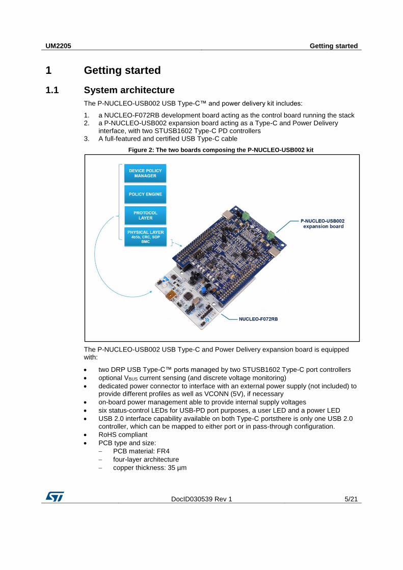
1.1 System architecture
The P-NUCLEO-USB002 USB Type-C™ and power delivery kit includes:
1. a NUCLEO-F072RB development board acting as the control board running the stack 2. a P-NUCLEO-USB002 expansion board acting as a Type-C and Power Delivery
interface, with two STUSB1602 Type-C PD controllers 3. A full-featured and certified USB Type-C cable
Figure 2: The two boards composing the P-NUCLEO-USB002 kit
The P-NUCLEO-USB002 USB Type-C and Power Delivery expansion board is equipped with:
two DRP USB Type-C™ ports managed by two STUSB1602 Type-C port controllers
optional VBUS current sensing (and discrete voltage monitoring)
dedicated power connector to interface with an external power supply (not included) to provide different profiles as well as VCONN (5V), if necessary
on-board power management able to provide internal supply voltages
six status-control LEDs for USB-PD port purposes, a user LED and a power LED
USB 2.0 interface capability available on both Type-C portsthere is only one USB 2.0 controller, which can be mapped to either port or in pass-through configuration.
RoHS compliant
PCB type and size:
PCB material: FR4
four-layer architecture
copper thickness: 35 µm
Getting started UM2205
6/21 DocID030539 Rev 1
The NUCLEO-F072RB board includes:
an STM32F072RBT6 32-bit microcontroller based on ARM® Cortex®-M0 with 128-Kbytes of Flash memory, 16-Kbytes of SRAM and a USB 2.0 full speed data interface in a LQFP64 package
extension resources:
Arduino Uno revision 3 connectivity
ST morpho extension pin headers for full access to all STM32 I/Os
on-board ST-LINK/V2-1 debugger/programmer with SWD connector:
selection-mode switch to use the kit as a standalone ST-LINK/V2-1
flexible board power supply:
USB VBUS on Type-B connector or external source
Power management access point
LEDs:
USB communication (LD1)
user LED (LD2)
power LED (LD3)
push buttons:
USER
RESET
USB re-enumeration capability; interfaces supported on USB:
Virtual Com port
Mass storage
Debug port
Supported by various integrated development environments (IDEs):
IAR™
Keil®
GCC-based IDEs
The NUCLEO-F072RB included in the kit has a different solder bridge configuration with respect to the default one (see Table 1: "Solder bridges and resistors to be modified")
1.2 NUCLEO-F072RB STM32 Nucleo board
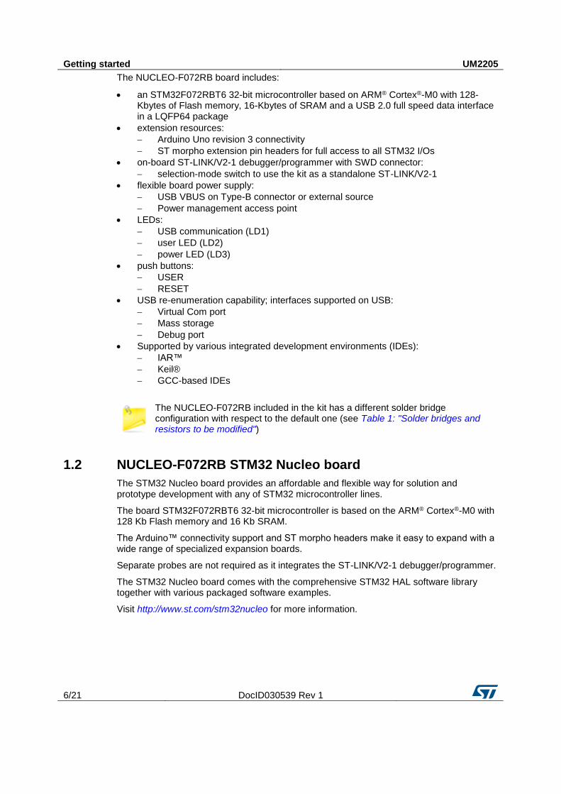
The STM32 Nucleo board provides an affordable and flexible way for solution and prototype development with any of STM32 microcontroller lines.
The board STM32F072RBT6 32-bit microcontroller is based on the ARM® Cortex®-M0 with 128 Kb Flash memory and 16 Kb SRAM.
The Arduino™ connectivity support and ST morpho headers make it easy to expand with a wide range of specialized expansion boards.
Separate probes are not required as it integrates the ST-LINK/V2-1 debugger/programmer.
The STM32 Nucleo board comes with the comprehensive STM32 HAL software library together with various packaged software examples.
Visit http://www.st.com/stm32nucleo for more information.
UM2205 Getting started
DocID030539 Rev 1 7/21
Figure 3: STM32 Nucleo development board
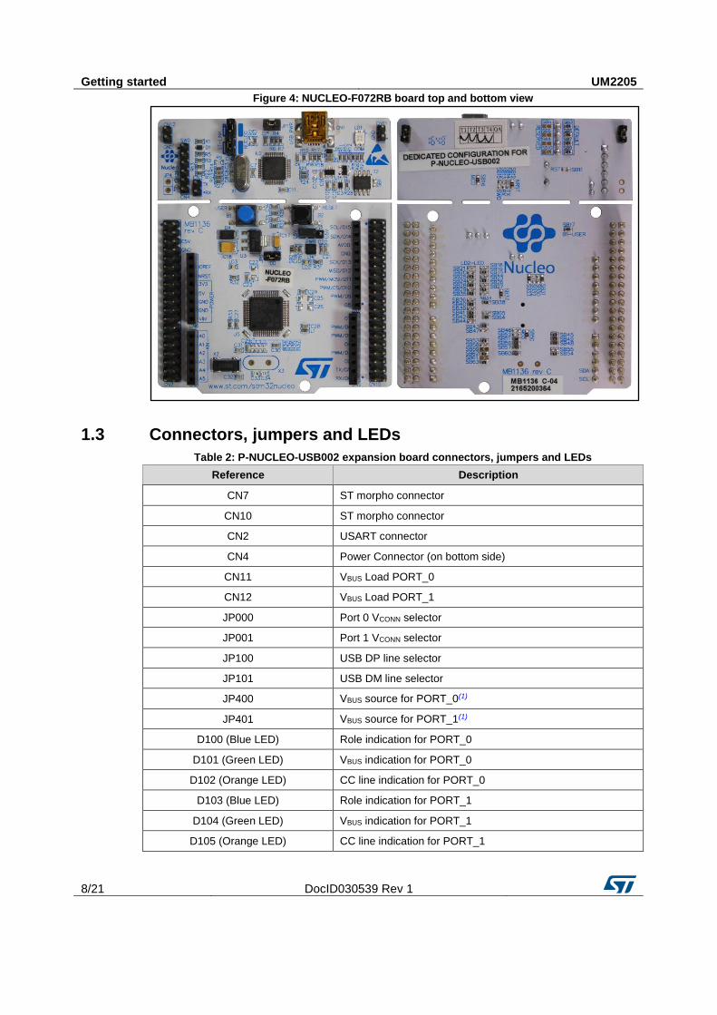
The solder bridge configuration on the NUCLEO-F072RB Nucleo board is customized to support USB PD applications (see Table 1: "Solder bridges and resistors to be modified" and Figure 4: "NUCLEO-F072RB board top and bottom view").
For further information, please refer to user manual UM1724 STM32 Nucleo-64 boards on www.st.com.
Table 1: Solder bridges and resistors to be modified
Bridge reference
State Description
SB13 OFF
PA2 and PA3 on STM32F103CBT6 (ST-LINK MCU) are disconnected from PA3 and PA2 of the STM32F072RBT6 MCU. SB14
SB15 OFF The SWO signal is not connected to PB3 on STM32F072RBT6 MCU.
SB21 OFF Green user LED LD2 is not connected to PA5 on STM32F072RBT6 MCU.
R34 OFF
LSE not used: PC14 and PC15 used as GPIOs instead of low speed clock. R36
SB48 ON
SB49
SB62
ON
To connect another USART (not the default USART2) to STLINK MCU, using flying wires between ST morpho connector and CN3.
SB13 and SB14 should be OFF. SB63
Getting started UM2205
8/21 DocID030539 Rev 1
Figure 4: NUCLEO-F072RB board top and bottom view
1.3 Connectors, jumpers and LEDs
Table 2: P-NUCLEO-USB002 expansion board connectors, jumpers and LEDs
Reference Description
CN7 ST morpho connector
CN10 ST morpho connector
CN2 USART connector
CN4 Power Connector (on bottom side)
CN11 VBUS Load PORT_0
CN12 VBUS Load PORT_1
JP000 Port 0 VCONN selector
JP001 Port 1 VCONN selector
JP100 USB DP line selector
JP101 USB DM line selector
JP400 VBUS source for PORT_0(1)
JP401 VBUS source for PORT_1(1)
D100 (Blue LED) Role indication for PORT_0
D101 (Green LED) VBUS indication for PORT_0
D102 (Orange LED) CC line indication for PORT_0
D103 (Blue LED) Role indication for PORT_1
D104 (Green LED) VBUS indication for PORT_1
D105 (Orange LED) CC line indication for PORT_1
UM2205 Getting started
DocID030539 Rev 1 9/21
Reference Description
D106 (Blue LED) 3.3V power
D107 (Blue LED) User LED
Notes:
(1)allows using the 5V from the NUCLEO-F072RB as VBUS when no external power supply is available and only in the provider role – mainly used for demo purposes. If an external power supply is connected, the jumper must be left open
Refer to UM2191 on www.st.com for further details.
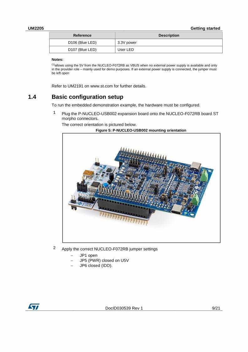
1.4 Basic configuration setup
To run the embedded demonstration example, the hardware must be configured.
1 Plug the P-NUCLEO-USB002 expansion board onto the NUCLEO-F072RB board ST morpho connectors.
The correct orientation is pictured below.
Figure 5: P-NUCLEO-USB002 mounting orientation
2 Apply the correct NUCLEO-F072RB jumper settings
JP1 open
JP5 (PWR) closed on U5V
JP6 closed (IDD).
Getting started UM2205
10/21 DocID030539 Rev 1
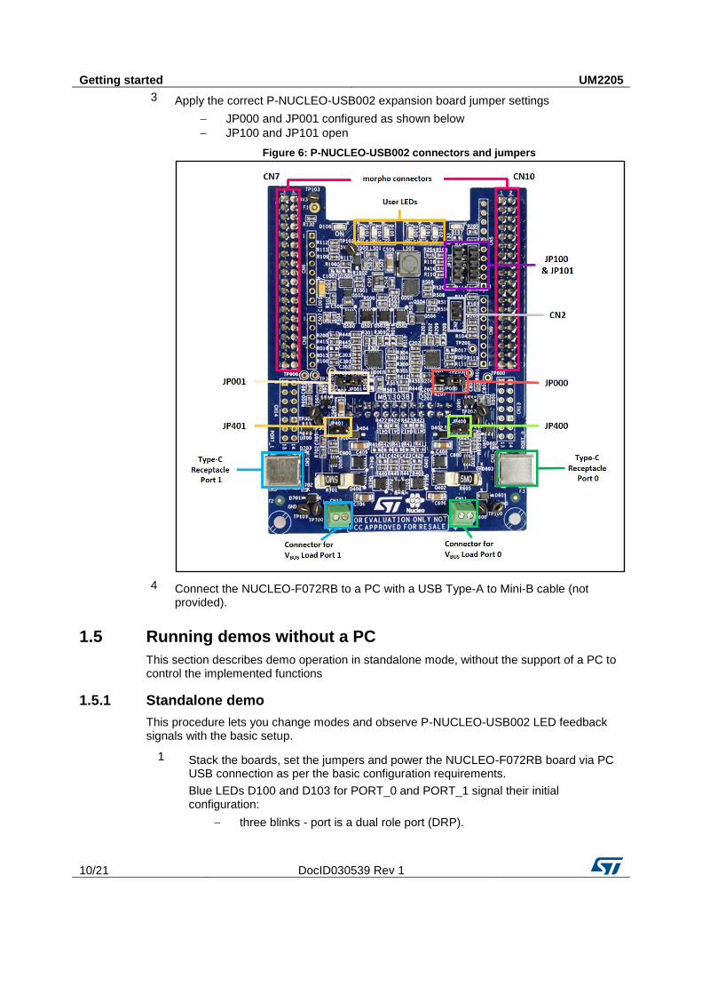
3 Apply the correct P-NUCLEO-USB002 expansion board jumper settings
JP000 and JP001 configured as shown below
JP100 and JP101 open
Figure 6: P-NUCLEO-USB002 connectors and jumpers
4 Connect the NUCLEO-F072RB to a PC with a USB Type-A to Mini-B cable (not provided).
1.5 Running demos without a PC
This section describes demo operation in standalone mode, without the support of a PC to control the implemented functions
1.5.1 Standalone demo
This procedure lets you change modes and observe P-NUCLEO-USB002 LED feedback signals with the basic setup.
1 Stack the boards, set the jumpers and power the NUCLEO-F072RB board via PC USB connection as per the basic configuration requirements.
Blue LEDs D100 and D103 for PORT_0 and PORT_1 signal their initial configuration:
three blinks - port is a dual role port (DRP).
UM2205 Getting started
DocID030539 Rev 1 11/21
2 Connect the two Type-C receptacles on the expansion board using the USB Type-C cables provided
Blue LEDs D100 and D103 for PORT_0 and PORT_1 signal the current role of the port:
one blink - port is a provider
two blinks - port is a consumer
3 Change the orientation of the cables.
Orange LEDs D102 and D105 for PORT_0 and PORT_1 signal the CC line used:
one blink - CC1
two blinks - CC2
4 Wait until an explicit contract is established.
Green LEDs D101 and D104 for PORT_0 and PORT_1 signal:
LED on - the port has defined an explicit contract with the port partner
LED blinking - the port, as provider or consumer, is supplying or is sinking power, respectively
LED off - no power is being provided or sunk on the port
1.5.2 Standalone demo with external hardware connected
This procedure lets you change modes and observe P-NUCLEO-USB002 LED feedback signals with an external port partner.
In the Provider and DRP roles, the exposed power profiles are dummies.
1 Stack the boards, set the jumpers and power the NUCLEO-F072RB board via PC USB connection as per the basic configuration requirements.
Blue LEDs D100 and D103 for PORT_0 and PORT_1 signal their initial configuration:
three blinks - port is a dual role port (DRP).
2 Connect P-NUCLEO-USB002 CN2 to NUCLEO-F072RB CN3 with the female wires included in the package.
Connections:
CN2_1 to CN3_TX
CN2_2 to CN3_RX
3 Connect the Type-C to Type-C cable to one of the expansion board ports
The initial role of both ports is DRP.
Getting started UM2205
12/21 DocID030539 Rev 1
4 Connect the other plug of the USB Type-C cable to an external port partner.
Blue LEDs D100 and D103 for PORT_0 and PORT_1 signal the current role of the port:
one blink - port is a provider
two blinks - port is a consumer
Orange LEDs D102 and D105 for PORT_0 and PORT_1 signal the CC line used:
one blink - CC1
two blinks - CC2
Green LEDs D101 and D104 for PORT_0 and PORT_1 signal:
LED on - the port has defined an explicit contract with the port partner
LED blinking - the port, as provider or consumer, is supplying or is sinking power, respectively
LED off - no power is being provided or sunk on the port
5 Use the command line interface to interact with the application.
1.6 Running demos with a PC
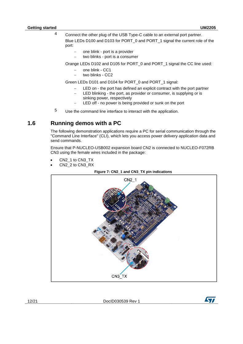
The following demonstration applications require a PC for serial communication through the "Command Line Interface" (CLI), which lets you access power delivery application data and send commands.
Ensure that P-NUCLEO-USB002 expansion board CN2 is connected to NUCLEO-F072RB CN3 using the female wires included in the package:
CN2_1 to CN3_TX
CN2_2 to CN3_RX
Figure 7: CN2_1 and CN3_TX pin indications
UM2205 Getting started
DocID030539 Rev 1 13/21
1.6.1 Standalone demo with PC
1 Connect the NUCLEO-F072RB board to the PC via the virtual COM port with a standard serial terminal program.
Configuration:
Baudrate: 115200
Data bit: 8
Parity: none
Stop bit: 1
Hardware Flow Control: None
2 Use the CLI to access port status and profile information.
When the port is a consumer, you can command it to request a different profile, if available.
A "welcome message" is shown in the terminal on board startup or reset (reset button on NUCLEO-F072RB board).
Getting started UM2205
14/21 DocID030539 Rev 1
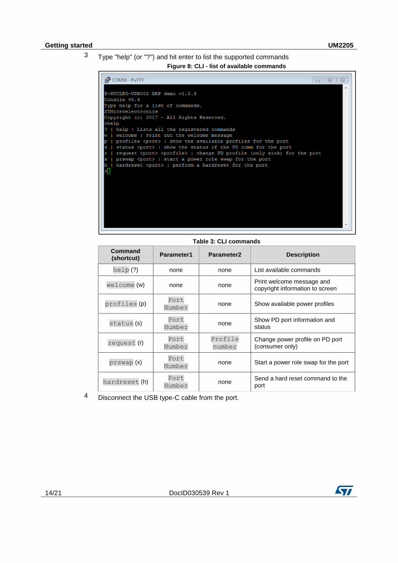
3 Type "help" (or "?") and hit enter to list the supported commands
Figure 8: CLI - list of available commands
Table 3: CLI commands
Command (shortcut)
Parameter1 Parameter2 Description
help (?) none none List available commands
welcome (w) none none Print welcome message and copyright information to screen
profiles (p) Port
Number none Show available power profiles
status (s) Port
Number none
Show PD port information and status
request (r) Port
Number
Profile
number
Change power profile on PD port (consumer only)
prswap (x) Port
Number none Start a power role swap for the port
hardreset (h) Port
Number none
Send a hard reset command to the port
4 Disconnect the USB type-C cable from the port.
UM2205 Getting started
DocID030539 Rev 1 15/21
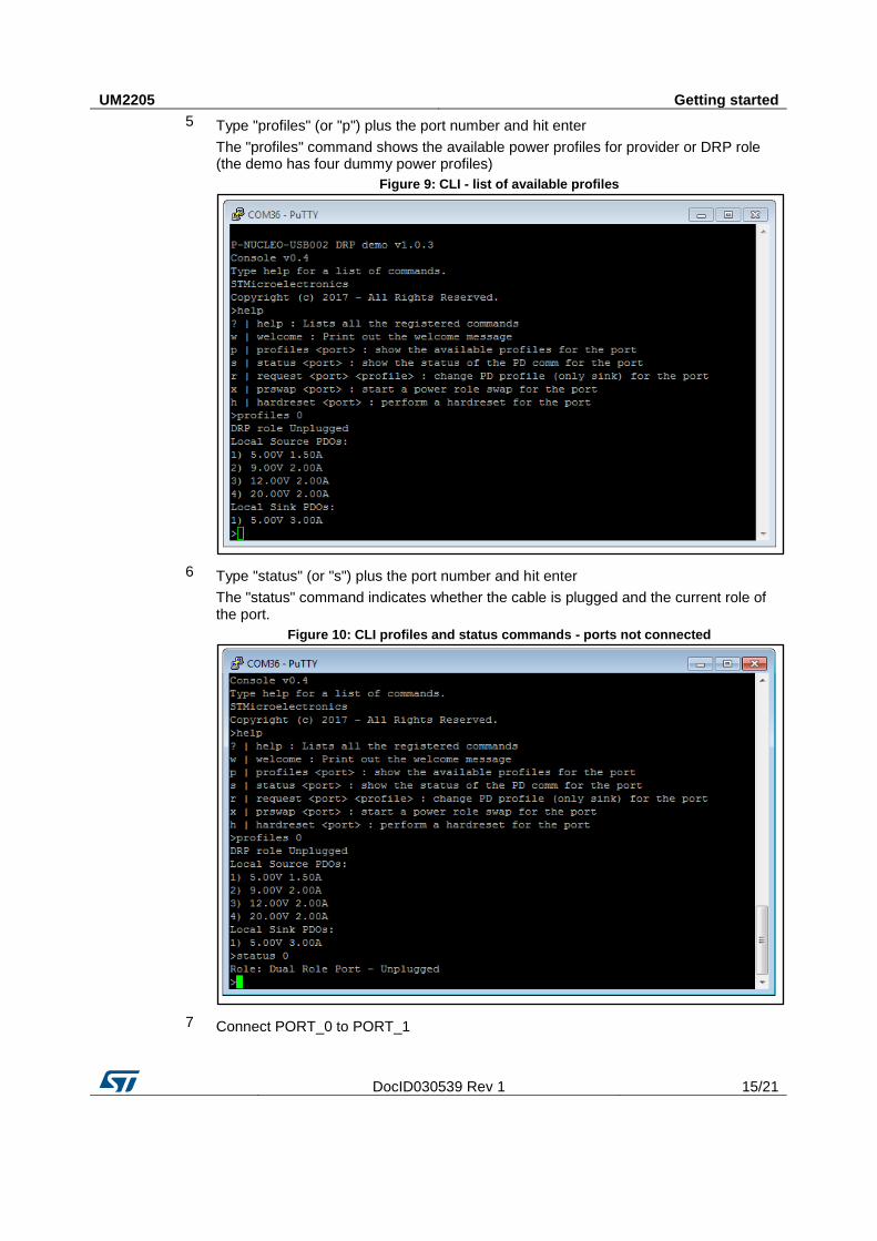
5 Type "profiles" (or "p") plus the port number and hit enter
The "profiles" command shows the available power profiles for provider or DRP role (the demo has four dummy power profiles)
Figure 9: CLI - list of available profiles
6 Type "status" (or "s") plus the port number and hit enter
The "status" command indicates whether the cable is plugged and the current role of the port.
Figure 10: CLI profiles and status commands - ports not connected
7 Connect PORT_0 to PORT_1
Getting started UM2205
16/21 DocID030539 Rev 1
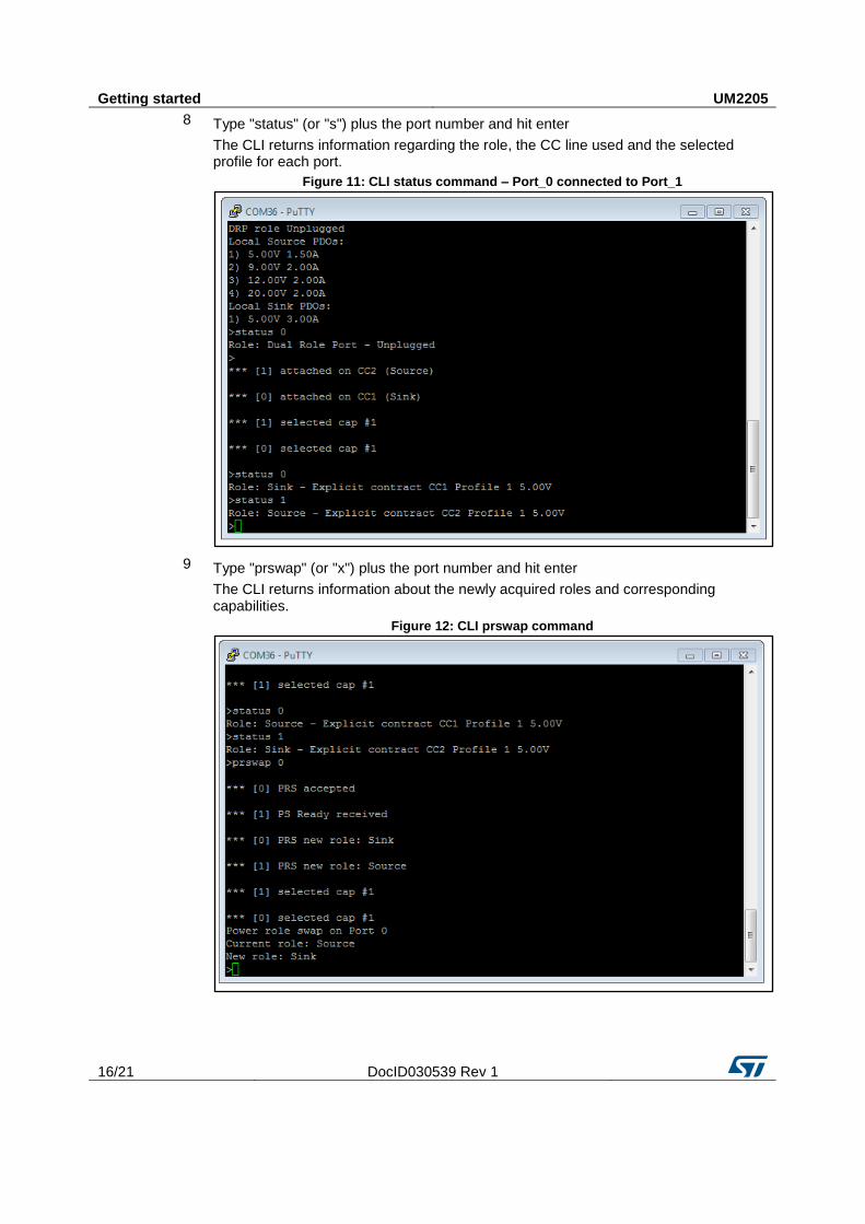
8 Type "status" (or "s") plus the port number and hit enter
The CLI returns information regarding the role, the CC line used and the selected profile for each port.
Figure 11: CLI status command – Port_0 connected to Port_1
9 Type "prswap" (or "x") plus the port number and hit enter
The CLI returns information about the newly acquired roles and corresponding capabilities.
Figure 12: CLI prswap command
UM2205 Getting started
DocID030539 Rev 1 17/21
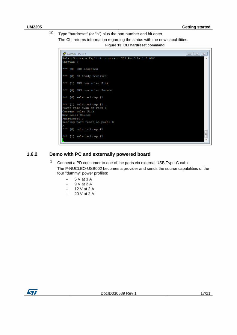
10 Type "hardreset" (or "h") plus the port number and hit enter
The CLI returns information regarding the status with the new capabilities.
Figure 13: CLI hardreset command
1.6.2 Demo with PC and externally powered board
1 Connect a PD consumer to one of the ports via external USB Type-C cable
The P-NUCLEO-USB002 becomes a provider and sends the source capabilities of the four "dummy" power profiles:
5 V at 3 A
9 V at 2 A
12 V at 2 A
20 V at 2 A
Getting started UM2205
18/21 DocID030539 Rev 1
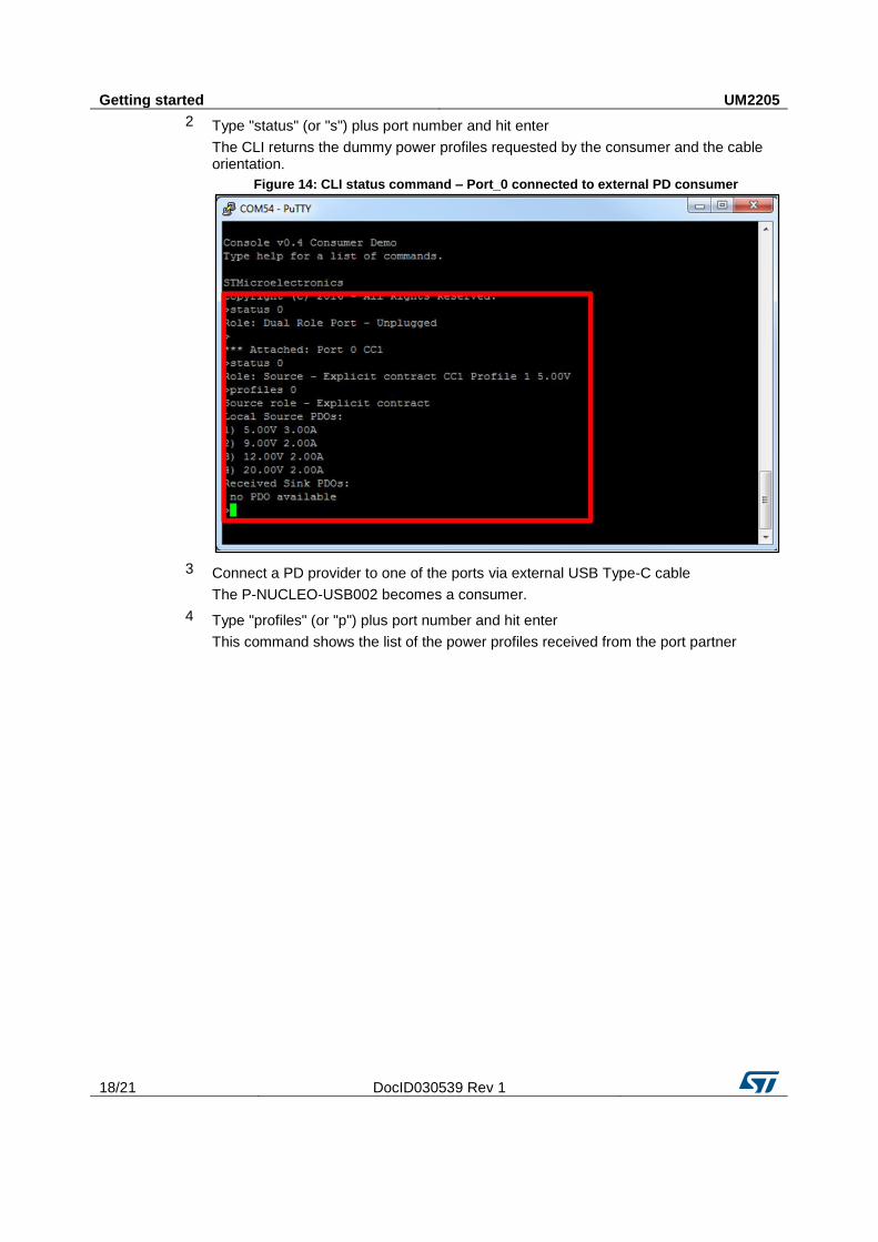
2 Type "status" (or "s") plus port number and hit enter
The CLI returns the dummy power profiles requested by the consumer and the cable orientation.
Figure 14: CLI status command – Port_0 connected to external PD consumer
3 Connect a PD provider to one of the ports via external USB Type-C cable
The P-NUCLEO-USB002 becomes a consumer.
4 Type "profiles" (or "p") plus port number and hit enter
This command shows the list of the power profiles received from the port partner
UM2205 Getting started
DocID030539 Rev 1 19/21
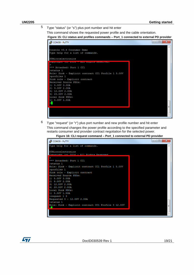
5 Type "status" (or "s") plus port number and hit enter
This command shows the requested power profile and the cable orientation.
Figure 15: CLI status and profiles commands – Port_1 connected to external PD provider
6 Type "request" (or "r") plus port number and new profile number and hit enter
This command changes the power profile according to the specified parameter and restarts consumer and provider contract negotiation for the selected power.
Figure 16: CLI request command – Port_1 connected to external PD provider
Revision history UM2205
20/21 DocID030539 Rev 1
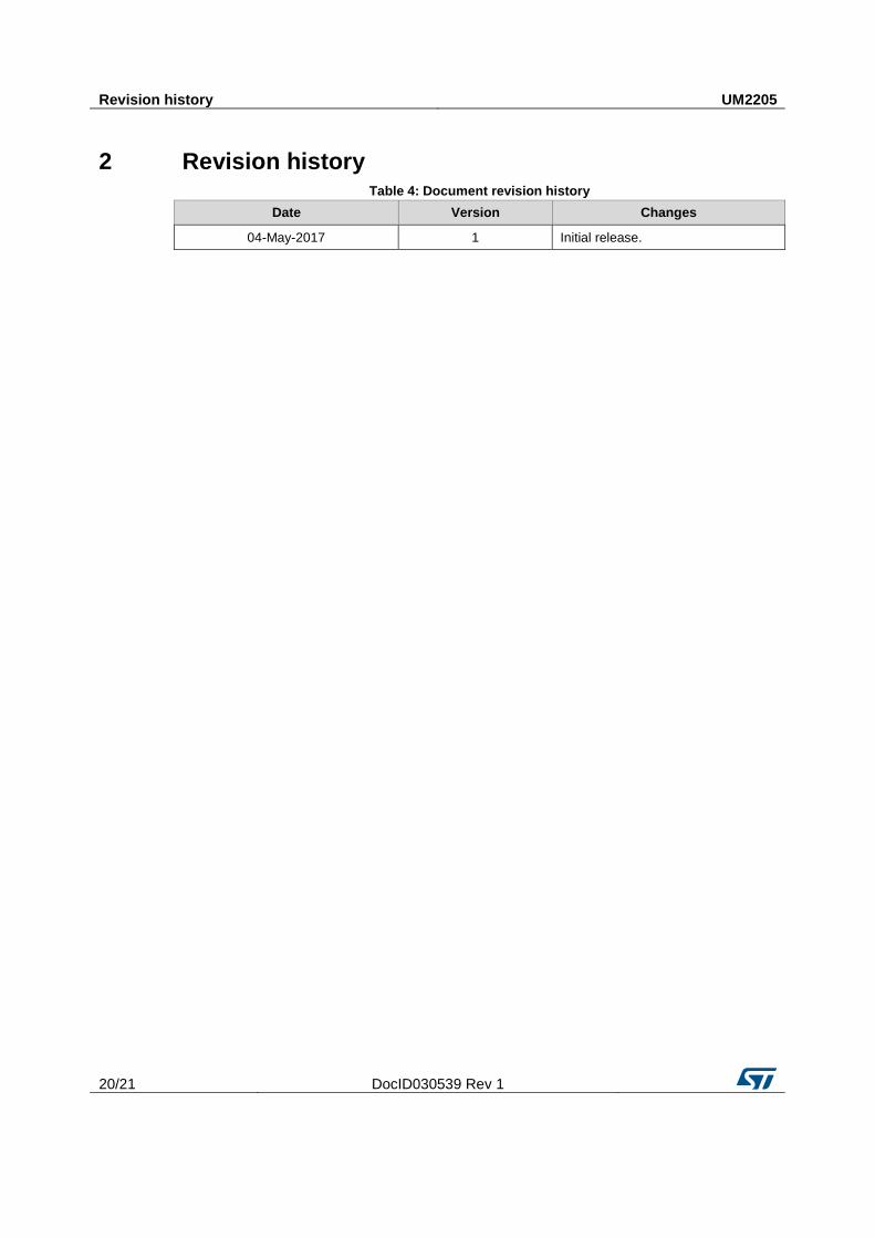
2 Revision history Table 4: Document revision history
Date Version Changes
04-May-2017 1 Initial release.
UM2205
DocID030539 Rev 1 21/21
IMPORTANT NOTICE – PLEASE READ CAREFULLY
STMicroelectronics NV and its subsidiaries (“ST”) reserve the right to make changes, corrections, enhancements, modifications , and improvements to ST products and/or to this document at any time without notice. Purchasers should obtain the latest relevant information on ST products before placing orders. ST products are sold pursuant to ST’s terms and conditions of sale in place at the time of order acknowledgement.
Purchasers are solely responsible for the choice, selection, and use of ST products and ST assumes no liability for application assistance or the design of Purchasers’ products.
No license, express or implied, to any intellectual property right is granted by ST herein.
Resale of ST products with provisions different from the information set forth herein shall void any warranty granted by ST for such product.
ST and the ST logo are trademarks of ST. All other product or service names are the property of their respective owners.
Information in this document supersedes and replaces information previously supplied in any prior versions of this document.
© 2017 STMicroelectronics – All rights reserved