Embed Size (px)
Citation preview

Maxim > Design Support > Technical Documents > Application Notes > Interface Circuits > APP 5388Maxim > Design Support > Technical Documents > Application Notes > Microcontrollers > APP 5388
Keywords: uC, evaluation kit, AFE, smart card, microcontroller, Rowley, IAR embedded workbench
APPLICATION NOTE 5388
Getting Started with the DS8005 Evaluation KitApr 01, 2013
Abstract: This application note describes how to build, debug, and run applications on the on-board MAXQ622microcontroller to interface with the DS8005 dual smart card interface. This is demonstrated in both IAREmbedded Workbench and the Rowley CrossWorks IDE, using sample code provided with the kit.
IntroductionThe DS8005 dual smart card interface is a low-cost, dual analog front-end (AFE) for an IC card readerinterface that needs to communicate with two smart cards in a mutually exclusive fashion. The analog interfaceis designed for use in ISO 7816, EMV®, and B-CAS applications. Additionally, the device is designed forapplications where the C4/C8 (AUX1/AUX2) contacts are not required on either card interface. The DS8005 isdesigned to be used with microcontrollers that contain an ISO 7816 UART, or have the bandwidth to run thisprotocol in software by bit-banging IO ports.
In the DS8005 evaluation kit (DS8005-KIT), the DS8005 is provided in a 28-pin SOIC package. A smaller 28-pin TSSOP package is also available.
Setting Up the DS8005 Evaluation KitA photo of the DS8005 evaluation kit board is provided in Figure 1. The following hardware components arecontained in the evaluation kit and are used for implementing and verifying the demonstrated program:
1. DS8005 evaluation kit board2. On-board MAXQ622 microcontroller for developing smart card applications3. USB-to-JTAG dongle for programming the MAXQ6224. One ACOS3 smart card5. Two card sockets (one smart card and one SIM/SAM card)6. 2-line liquid-crystal display (LCD) screen for the user interface7. Level-shifted RS-232 interface for debugging and the user interface8. Pushbuttons for reset and user input9. Regulated power supply (5V, ±5%, 300mA, center positive)
Table 1 shows all the jumpers and includes a description of what each setting does. Settings highlighted inblue indicate the default settings. See Figure 2 for jumper locations.
Page 1 of 22
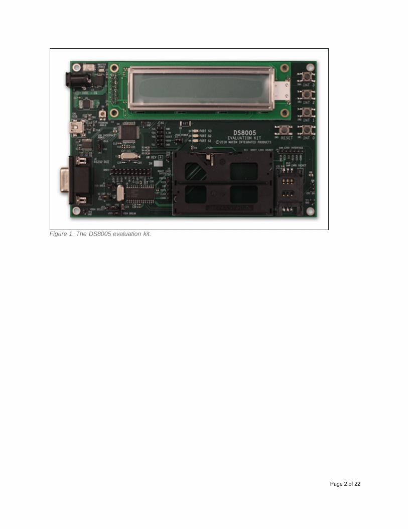
Figure 1. The DS8005 evaluation kit.
Page 2 of 22
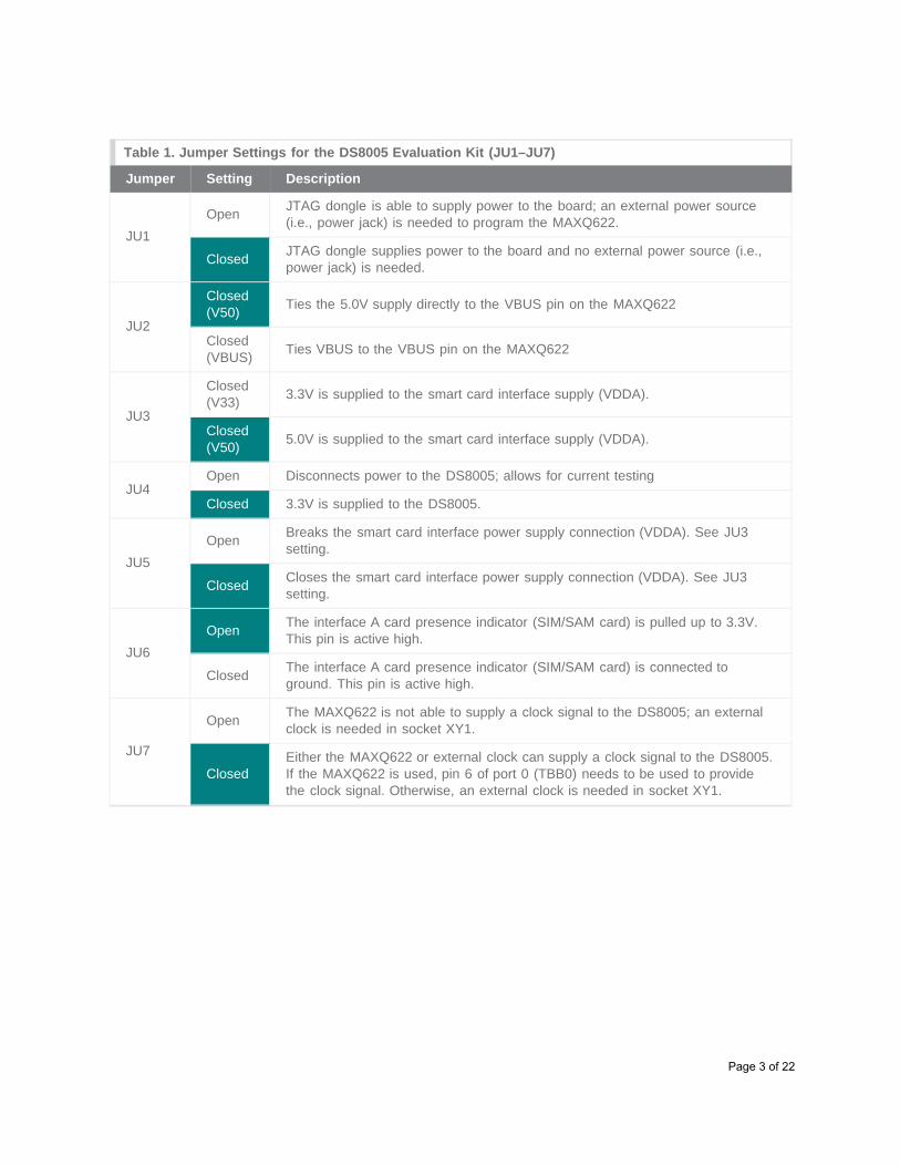
Table 1. Jumper Settings for the DS8005 Evaluation Kit (JU1–JU7)
Jumper Setting Description
JU1Open JTAG dongle is able to supply power to the board; an external power source
(i.e., power jack) is needed to program the MAXQ622.
Closed JTAG dongle supplies power to the board and no external power source (i.e.,power jack) is needed.
JU2
Closed(V50) Ties the 5.0V supply directly to the VBUS pin on the MAXQ622
Closed(VBUS) Ties VBUS to the VBUS pin on the MAXQ622
JU3
Closed(V33) 3.3V is supplied to the smart card interface supply (VDDA).
Closed(V50) 5.0V is supplied to the smart card interface supply (VDDA).
JU4Open Disconnects power to the DS8005; allows for current testing
Closed 3.3V is supplied to the DS8005.
JU5Open Breaks the smart card interface power supply connection (VDDA). See JU3
setting.
Closed Closes the smart card interface power supply connection (VDDA). See JU3setting.
JU6Open The interface A card presence indicator (SIM/SAM card) is pulled up to 3.3V.
This pin is active high.
Closed The interface A card presence indicator (SIM/SAM card) is connected toground. This pin is active high.
JU7
Open The MAXQ622 is not able to supply a clock signal to the DS8005; an externalclock is needed in socket XY1.
ClosedEither the MAXQ622 or external clock can supply a clock signal to the DS8005.If the MAXQ622 is used, pin 6 of port 0 (TBB0) needs to be used to providethe clock signal. Otherwise, an external clock is needed in socket XY1.
Page 3 of 22

Figure 2. The location of all the jumpers on the DS8005 evaluation kit.
Setting Up the FTDI DriversThe USB-to-JTAG dongle is designed to connect to the host PC over a USB interface, which allows softwarerunning on the host (such as a program loading utility or application debugger) to communicate with the JTAGloader/debug interface on the MAXQ622 microcontroller. It uses the FTDI USB-to-serial IC to communicatewith the USB interface on the PC. Before the FTDI interface can be used, the proper drivers must first beinstalled.
Note: The most up-to-date versions of all FTDI drivers and utilities can always be downloaded directly fromFTDI's website at: www.ftdichip.com. The DS8005 evaluation kit CD contains the latest versions of theseutilities and drivers at the time the CD was last updated.
Installing FTDI Drivers for the FT232RLAll required drivers for the FTDI USB-to-serial IC can be installed by running the FTDI driver setup executable.To run this executable, navigate to the install/FTDI_Drivers directory of the CD and run the executable:CDM20814_Setup.exe.
Once this setup executable has been run, you will be able to connect the USB-to-JTAG dongle to the PCusing the USB interface cable.
When the USB cable is connected with USB-to-JTAG dongle, you will see notices in the Windows notificationarea that new hardware has been found, followed by a notice that the hardware installed correctly.
If you have difficulty installing the FTDI drivers correctly using the driver setup executable provided on theDS8005 evaluation kit CD, you can download and unpack the standard driver package, available on FTDI'swebsite at www.ftdichip.com/Drivers/VCP.htm. The driver package can be downloaded from this page and willbe named similar to “CDM20814_WHQL_Certified.zip”, where the five-digit number depends on the exactversion of the driver that is currently available.
There are detailed instructions for installing the drivers provided by FTDI for Windows XP®, Windows Vista®,and Windows® 7; these are available in application note form:www.ftdichip.com/Support/Documents/InstallGuides.htm
Page 4 of 22

See also www.ftdichip.com/Support/Documents/AppNotes.htm for additional information from FTDI.
Determining the COM Port Location of the USB-to-Serial InterfaceThe USB-to-serial interface provided by the FT232RL chip on the USB-to-JTAG dongle uses the virtual COMport (VCP) device model on Windows. This means that the USB-to-serial bridge appears as a standard COMport and can be used by any Windows application that has the ability to communicate over a COM port.
However, for an application (such as MAX-IDE or IAR Embedded Workbench®) to communicate with the VCP,the application must be configured by the user to use the correct COM port that has been assigned to theUSB-to-serial interface. This COM port number may vary depending on previous devices that have been usedand previous USB-to-serial drivers that have been installed.
To determine the current COM port number that has been assigned to the VCP, open the Device Managerutility in Windows.
Opening Device Manager in Windows 7Method 1: Click the Windows Start menu, followed by Control Panel. Next, click System and Security,followed by Device Manager.
Method 2: Click the Windows Start menu. In the search box, type “devmgmt.msc”, and hit Enter.
In the Device Manager window, open the section of the tree display labeled Ports (COM & LPT). You will seea listing for USB Serial Port (COMX), where X is the number of the COM port that has been assigned.
Removing and Reinstalling the FTDI DriversIf you have connected a large number of different FTDI-based USB-to-serial-adapter devices to your system,or if you simply have many USB-to-serial-based devices installed, you may find that the VCP assigned to theUSB-to-JTAG dongle has a very high COM port number (such as COM23). Some tools (such as the IAREmbedded Workbench) may have difficulty working properly if the VCP number you are using is too high.
FTDI provides a graphical utility that can be used to remove all installations of the FTDI driver setautomatically. This should allow future installations of the FTDI driver to start at a more reasonable VCPnumber (usually COM3, depending on the configuration of your system).
The FTDI uninstallation utility is located in the install/FTDI_Uninstall directory on the CD. In this directory, runthe CDMuninstallerGUI.exe program. Note: Before proceeding, disconnect all USB-to-serial devices from yourPC.
In the CDM Uninstaller window, the Vendor ID field should read 0403, and the Product ID field should read6001. Click Add, and these values will be copied into the center window. At this point, you can click theRemove Devices button, and the utility will uninstall all instances of the FTDI driver set.
After running the CDM Uninstaller tool, you will have to reinstall the FTDI driver set by rerunning theCDM20814_Setup.exe executable in the install/FTDI_Drivers directory, as described above.
If you have difficulty getting the drivers to reinstall correctly after running the CDM Uninstaller tool, try addingthe following step: After running the CDM Uninstaller, but before running the CDM20814_Setup.exe
Page 5 of 22
executable, check the DRVSTORE directory, usually found in the Windows directory under the System32subdirectory. If you see directories named ftdibus_<xxxxx> or ftdiport_<xxxxx>, where <xxxxx> is a random-appearing string of hex digits, delete these directories before running the CDM20814_Setup.exe executable.This will remove the preinstalled copies of the drivers and allow the drivers to reinstall cleanly.
Configuring the FTDI Driver SettingsAfter installing the FTDI drivers and connecting the USB-to-JTAG adapter, there is an optional change you canmake to the FTDI driver settings. Generally, this setting’s change should improve the overall communicationsspeed of the USB-to-JTAG interface, which is used to load and debug code on the MAXQ622.
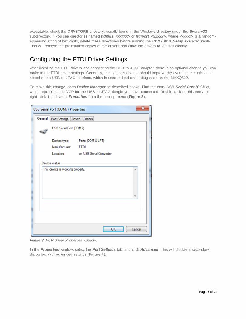
To make this change, open Device Manager as described above. Find the entry USB Serial Port (COMx),which represents the VCP for the USB-to-JTAG dongle you have connected. Double-click on this entry, orright-click it and select Properties from the pop-up menu (Figure 3).
Figure 3. VCP driver Properties window.
In the Properties window, select the Port Settings tab, and click Advanced. This will display a secondarydialog box with advanced settings (Figure 4).
Page 6 of 22
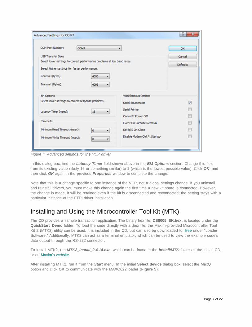
Figure 4. Advanced settings for the VCP driver.
In this dialog box, find the Latency Timer field shown above in the BM Options section. Change this fieldfrom its existing value (likely 16 or something similar) to 1 (which is the lowest possible value). Click OK, andthen click OK again in the previous Properties window to complete the change.
Note that this is a change specific to one instance of the VCP, not a global settings change. If you uninstalland reinstall drivers, you must make this change again the first time a new kit board is connected. However,the change is made, it will be retained even if the kit is disconnected and reconnected; the setting stays with aparticular instance of the FTDI driver installation.
Installing and Using the Microcontroller Tool Kit (MTK)The CD provides a sample transaction application. The binary hex file, DS8005_EK.hex, is located under theQuickStart_Demo folder. To load the code directly with a .hex file, the Maxim-provided Microcontroller ToolKit 2 (MTK2) utility can be used. It is included in the CD, but can also be downloaded for free under “LoaderSoftware.” Additionally, MTK2 can act as a terminal emulator, which can be used to view the example code’sdata output through the RS-232 connector.
To install MTK2, run MTK2_Install_2.4.14.exe, which can be found in the install/MTK folder on the install CD,or on Maxim’s website.
After installing MTK2, run it from the Start menu. In the initial Select device dialog box, select the MaxQoption and click OK to communicate with the MAXQ622 loader (Figure 5).
Page 7 of 22
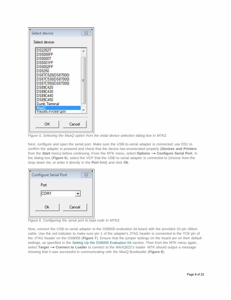
Figure 5. Selecting the MaxQ option from the initial device selection dialog box in MTK2.
Next, configure and open the serial port. Make sure the USB-to-serial adapter is connected; use DS1 toconfirm the adapter is powered and check that the device has enumerated properly (Devices and Printersfrom the Start menu) before continuing. From the MTK menu, select Options Configure Serial Port. Inthe dialog box (Figure 6), select the VCP that the USB-to-serial adapter is connected to (choose from thedrop-down list, or enter it directly in the Port field) and click Ok.
Figure 6. Configuring the serial port to load code in MTK2.
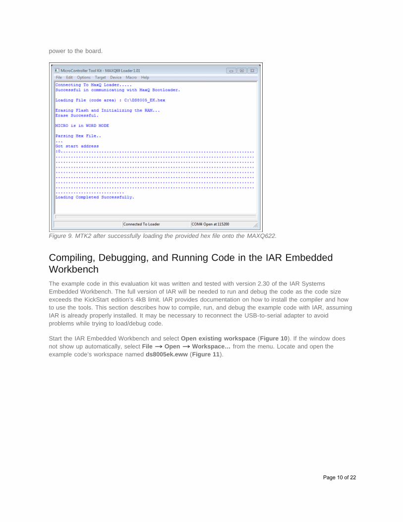
Now, connect the USB-to-serial adapter to the DS8005 evaluation kit board with the provided 10-pin ribboncable. Use the red indicator to make sure pin 1 of the adapter’s JTAG header is connected to the TCK pin ofthe JTAG header on the DS8005 (Figure 7). Ensure that the jumper settings on the board are on their defaultsettings, as specified in the Setting Up the DS8005 Evaluation Kit section. Then from the MTK menu again,select Target Connect to Loader to connect to the MAXQ622’s loader. MTK should output a messageshowing that it was successful in communicating with the MaxQ Bootloader (Figure 8).
Page 8 of 22
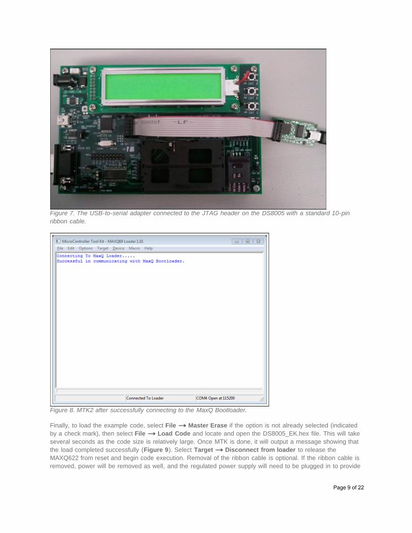
Figure 7. The USB-to-serial adapter connected to the JTAG header on the DS8005 with a standard 10-pinribbon cable.
Figure 8. MTK2 after successfully connecting to the MaxQ Bootloader.
Finally, to load the example code, select File Master Erase if the option is not already selected (indicatedby a check mark), then select File Load Code and locate and open the DS8005_EK.hex file. This will takeseveral seconds as the code size is relatively large. Once MTK is done, it will output a message showing thatthe load completed successfully (Figure 9). Select Target Disconnect from loader to release theMAXQ622 from reset and begin code execution. Removal of the ribbon cable is optional. If the ribbon cable isremoved, power will be removed as well, and the regulated power supply will need to be plugged in to provide
Page 9 of 22
power to the board.
Figure 9. MTK2 after successfully loading the provided hex file onto the MAXQ622.
Compiling, Debugging, and Running Code in the IAR EmbeddedWorkbenchThe example code in this evaluation kit was written and tested with version 2.30 of the IAR SystemsEmbedded Workbench. The full version of IAR will be needed to run and debug the code as the code sizeexceeds the KickStart edition’s 4kB limit. IAR provides documentation on how to install the compiler and howto use the tools. This section describes how to compile, run, and debug the example code with IAR, assumingIAR is already properly installed. It may be necessary to reconnect the USB-to-serial adapter to avoidproblems while trying to load/debug code.
Start the IAR Embedded Workbench and select Open existing workspace (Figure 10). If the window doesnot show up automatically, select File Open Workspace… from the menu. Locate and open theexample code’s workspace named ds8005ek.eww (Figure 11).
Page 10 of 22
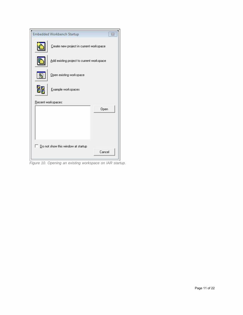
Figure 10. Opening an existing workspace on IAR startup.
Page 11 of 22
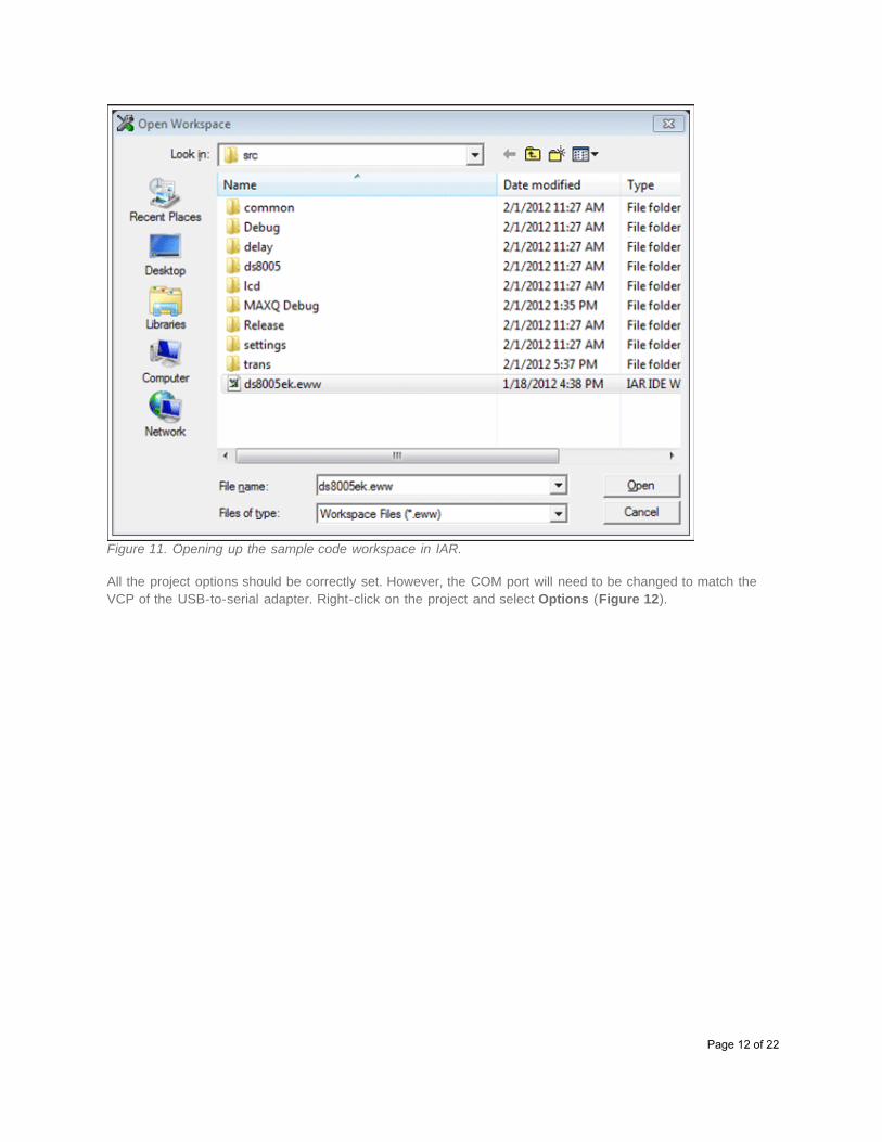
Figure 11. Opening up the sample code workspace in IAR.
All the project options should be correctly set. However, the COM port will need to be changed to match theVCP of the USB-to-serial adapter. Right-click on the project and select Options (Figure 12).
Page 12 of 22
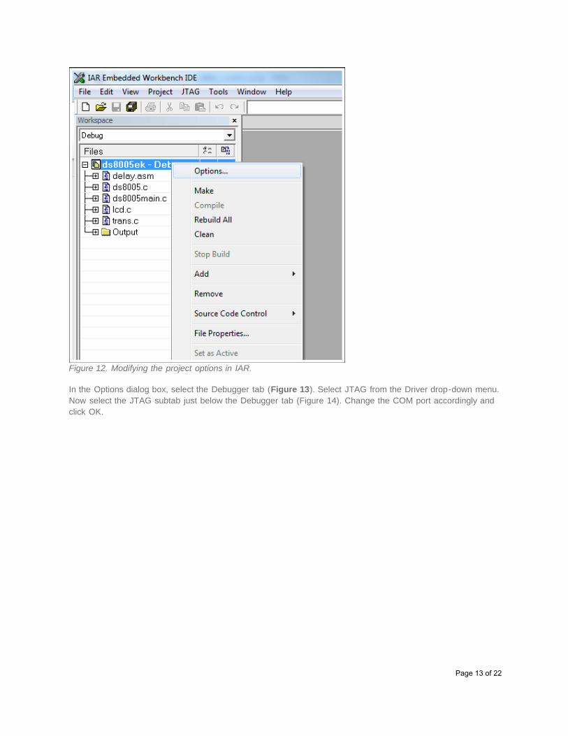
Figure 12. Modifying the project options in IAR.
In the Options dialog box, select the Debugger tab (Figure 13). Select JTAG from the Driver drop-down menu.Now select the JTAG subtab just below the Debugger tab (Figure 14). Change the COM port accordingly andclick OK.
Page 13 of 22
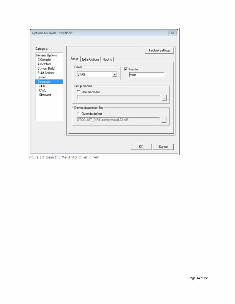
Figure 13. Selecting the JTAG driver in IAR.
Page 14 of 22
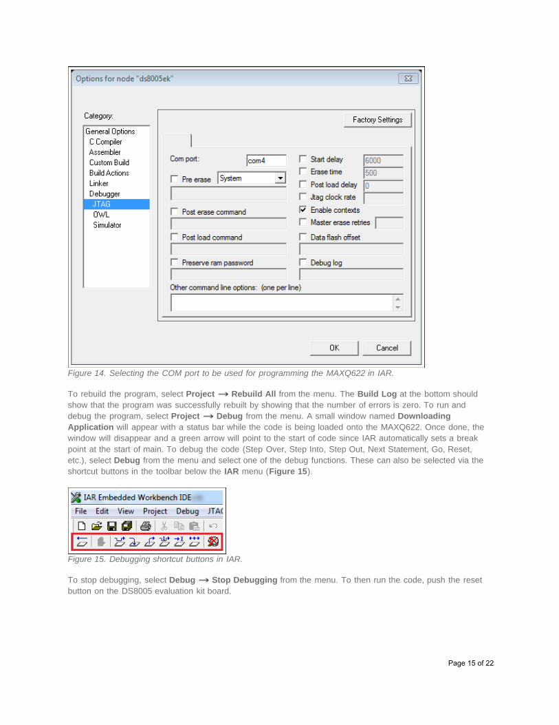
Figure 14. Selecting the COM port to be used for programming the MAXQ622 in IAR.
To rebuild the program, select Project Rebuild All from the menu. The Build Log at the bottom shouldshow that the program was successfully rebuilt by showing that the number of errors is zero. To run anddebug the program, select Project Debug from the menu. A small window named DownloadingApplication will appear with a status bar while the code is being loaded onto the MAXQ622. Once done, thewindow will disappear and a green arrow will point to the start of code since IAR automatically sets a breakpoint at the start of main. To debug the code (Step Over, Step Into, Step Out, Next Statement, Go, Reset,etc.), select Debug from the menu and select one of the debug functions. These can also be selected via theshortcut buttons in the toolbar below the IAR menu (Figure 15).
Figure 15. Debugging shortcut buttons in IAR.
To stop debugging, select Debug Stop Debugging from the menu. To then run the code, push the resetbutton on the DS8005 evaluation kit board.
Page 15 of 22
Compiling, Debugging, and Running Code in Rowley CrossWorksThe example code in this evaluation kit was written and tested with version 2.1.0.2011101107.12397 of RowleyCrossWorks. This section describes how to compile, run, and debug the example code with Rowley. It may benecessary to reconnect the USB-to-serial adapter to avoid problems while trying to connect to the device.
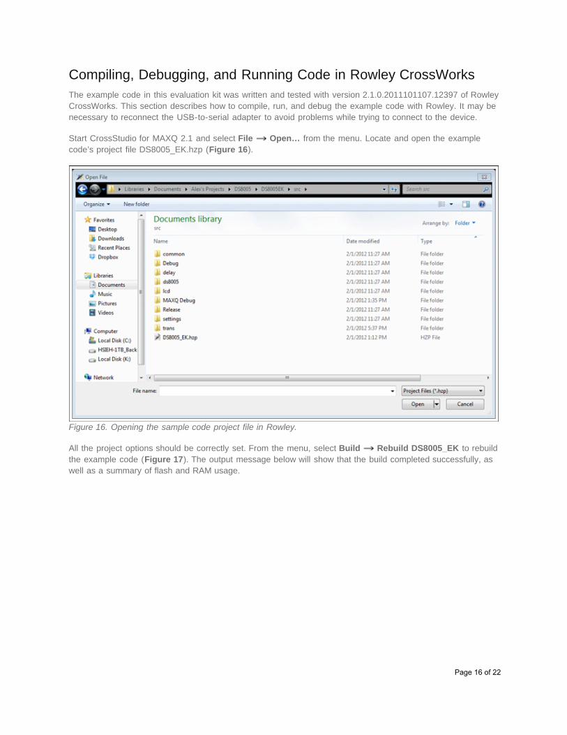
Start CrossStudio for MAXQ 2.1 and select File Open… from the menu. Locate and open the examplecode’s project file DS8005_EK.hzp (Figure 16).
Figure 16. Opening the sample code project file in Rowley.
All the project options should be correctly set. From the menu, select Build Rebuild DS8005_EK to rebuildthe example code (Figure 17). The output message below will show that the build completed successfully, aswell as a summary of flash and RAM usage.
Page 16 of 22
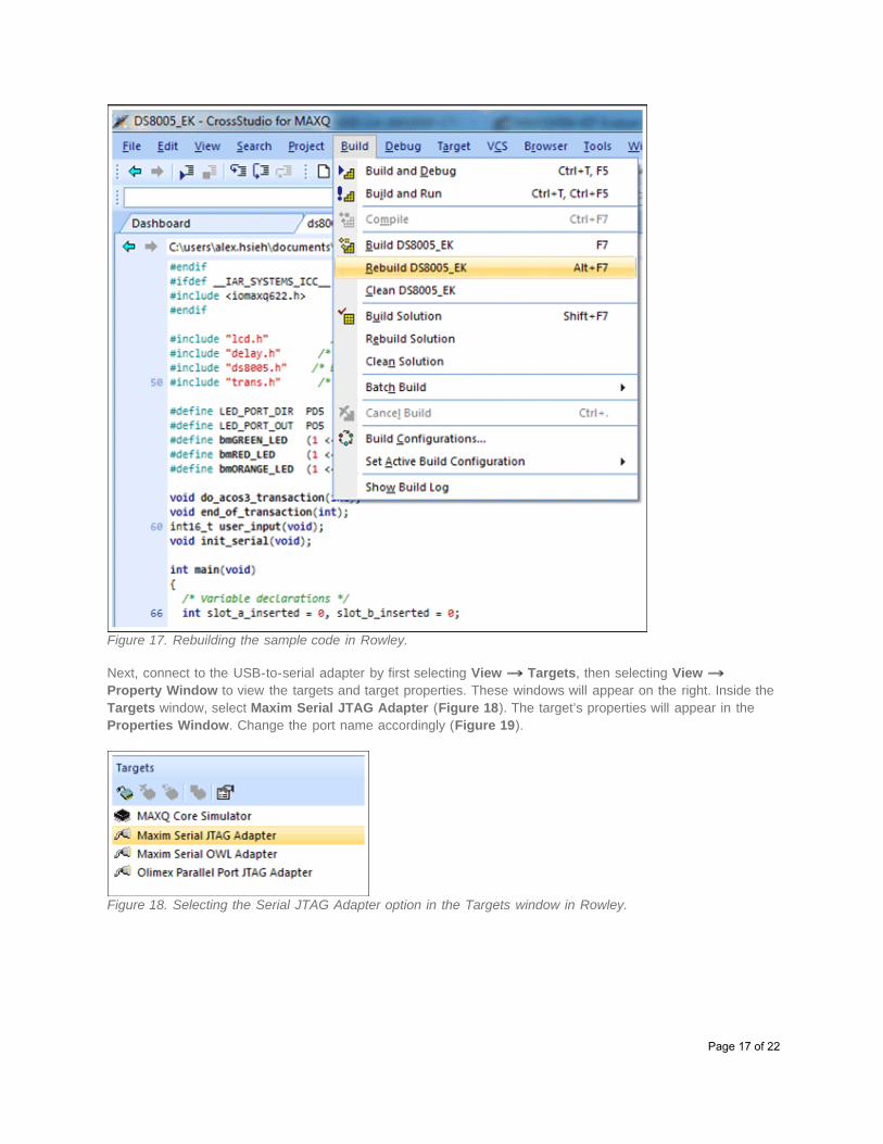
Figure 17. Rebuilding the sample code in Rowley.
Next, connect to the USB-to-serial adapter by first selecting View Targets, then selecting View Property Window to view the targets and target properties. These windows will appear on the right. Inside theTargets window, select Maxim Serial JTAG Adapter (Figure 18). The target’s properties will appear in theProperties Window. Change the port name accordingly (Figure 19).
Figure 18. Selecting the Serial JTAG Adapter option in the Targets window in Rowley.
Page 17 of 22
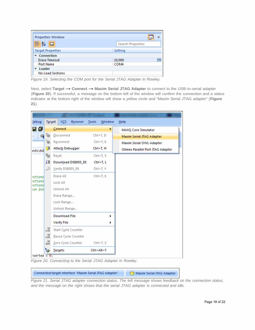
Figure 19. Selecting the COM port for the Serial JTAG Adapter in Rowley.
Next, select Target Connect Maxim Serial JTAG Adapter to connect to the USB-to-serial adapter(Figure 20). If successful, a message on the bottom left of the window will confirm the connection and a statusindicator at the bottom right of the window will show a yellow circle and “Maxim Serial JTAG adapter” (Figure21).
Figure 20. Connecting to the Serial JTAG Adapter in Rowley.
Figure 21. Serial JTAG adapter connection status. The left message shows feedback on the connection status,and the message on the right shows that the serial JTAG adapter is connected and idle.
Page 18 of 22
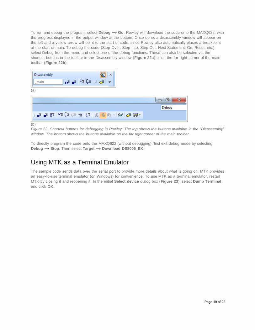
To run and debug the program, select Debug Go. Rowley will download the code onto the MAXQ622, withthe progress displayed in the output window at the bottom. Once done, a disassembly window will appear onthe left and a yellow arrow will point to the start of code, since Rowley also automatically places a breakpointat the start of main. To debug the code (Step Over, Step Into, Step Out, Next Statement, Go, Reset, etc.),select Debug from the menu and select one of the debug functions. These can also be selected via theshortcut buttons in the toolbar in the Disassembly window (Figure 22a) or on the far right corner of the maintoolbar (Figure 22b).
(a)
(b)Figure 22. Shortcut buttons for debugging in Rowley. The top shows the buttons available in the “Disassembly”window. The bottom shows the buttons available on the far right corner of the main toolbar.
To directly program the code onto the MAXQ622 (without debugging), first exit debug mode by selectingDebug Stop. Then select Target Download DS8005_EK.
Using MTK as a Terminal EmulatorThe sample code sends data over the serial port to provide more details about what is going on. MTK providesan easy-to-use terminal emulator (on Windows) for convenience. To use MTK as a terminal emulator, restartMTK by closing it and reopening it. In the initial Select device dialog box (Figure 23), select Dumb Terminal,and click OK.
Page 19 of 22
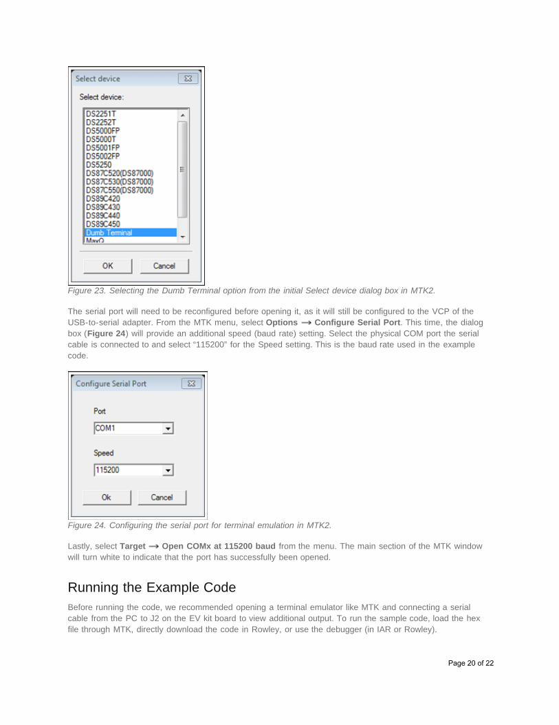
Figure 23. Selecting the Dumb Terminal option from the initial Select device dialog box in MTK2.
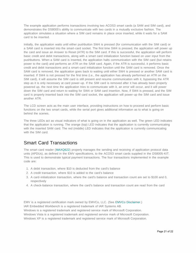
The serial port will need to be reconfigured before opening it, as it will still be configured to the VCP of theUSB-to-serial adapter. From the MTK menu, select Options Configure Serial Port. This time, the dialogbox (Figure 24) will provide an additional speed (baud rate) setting. Select the physical COM port the serialcable is connected to and select “115200” for the Speed setting. This is the baud rate used in the examplecode.
Figure 24. Configuring the serial port for terminal emulation in MTK2.
Lastly, select Target Open COMx at 115200 baud from the menu. The main section of the MTK windowwill turn white to indicate that the port has successfully been opened.
Running the Example CodeBefore running the code, we recommended opening a terminal emulator like MTK and connecting a serialcable from the PC to J2 on the EV kit board to view additional output. To run the sample code, load the hexfile through MTK, directly download the code in Rowley, or use the debugger (in IAR or Rowley).
Page 20 of 22
The example application performs transactions involving two ACOS3 smart cards (a SAM and SIM card), anddemonstrates the DS8005’s ability to communicate with two cards in a mutually exclusive fashion. Theapplication simulates a situation where a SIM card remains in place once inserted, while it waits for a SAMcard to be inserted.
Initially, the application waits until either pushbutton SW4 is pressed (for communication with the SIM card) ora SAM card is inserted into the smart-card socket. The first time SW4 is pressed, the application will power upthe card and issue an Answer to Reset (ATR) to the SIM card. If this is successful, the application will performbasic credit and debit transactions, along with a smart card initialization function based on user input from thepushbuttons. When a SAM card is inserted, the application halts communication with the SIM card (but retainspower to the card) and performs an ATR on the SAM card. Again, if the ATR is successful, it performs basiccredit and debit transactions and a smart-card initialization function until the SAM card is removed. Once theSAM card is removed, the application goes back to waiting until either SW4 is pressed or another SAM card isinserted. If SW4 is not pressed for the first time (i.e., the application has already performed an ATR on theSIM card), it will assume the SIM card is still present and resume communication with it, bypassing the ATRstep as it is only necessary at card power-up. If the SIM card is removed after it has already been properlypowered up, the next time the application tries to communicate with it, an error will occur, and it will powerdown the SIM card and return to waiting for SW4 or SAM card insertion. Now, if SW4 is pressed, and the SIMcard is properly inserted back into the SIM card socket, the application will power-up the SIM card and issueanother ATR.
The LCD screen acts as the main user interface, providing instructions on how to proceed and perform basicfunctions on the two smart cards, while the serial port gives additional information as to what is going onbehind the scenes.
The three LEDs act as visual indicators of what is going on in the application as well. The green LED indicatesthat the application is running. The orange (top) LED indicates that the application is currently communicatingwith the inserted SAM card. The red (middle) LED indicates that the application is currently communicatingwith the SIM card.
Smart Card TransactionsThe smart card reader (MAXQ622) properly manages the sending and receiving of application protocol dataunits (APDUs), as defined in the EMV specifications, to the ACOS3 smart cards supplied in the DS8005-KIT.This is used to demonstrate typical payment transactions. The four transactions implemented in the examplecode are:
1. A debit transaction, where $10 is deducted from the card’s balance2. A credit transaction, where $10 is added to the card’s balance3. A card-initialization transaction, where the card’s balance and transaction count are set to $100 and 0,
respectively4. A check-balance transaction, where the card’s balance and transaction count are read from the card
EMV is a registered certification mark owned by EMVCo, LLC. (See EMVCo Disclaimer.)IAR Embedded Workbench is a registered trademark of IAR Systems AB.Windows is a registered trademark and registered service mark of Microsoft Corporation.Windows Vista is a registered trademark and registered service mark of Microsoft Corporation.Windows XP is a registered trademark and registered service mark of Microsoft Corporation.
Page 21 of 22
Related Parts
DS8005 Smart Card Interface Free Samples
DS8005-KIT Evaluation Kit for the DS8005
MAXQ622 16-Bit Microcontrollers with Infrared Module and OptionalUSB
Free Samples
More InformationFor Technical Support: http://www.maximintegrated.com/supportFor Samples: http://www.maximintegrated.com/samplesOther Questions and Comments: http://www.maximintegrated.com/contact
Application Note 5388: http://www.maximintegrated.com/an5388APPLICATION NOTE 5388, AN5388, AN 5388, APP5388, Appnote5388, Appnote 5388 © 2013 Maxim Integrated Products, Inc.Additional Legal Notices: http://www.maximintegrated.com/legal
Page 22 of 22


![Skaffold - storage.googleapis.com · [getting-started getting-started] Hello world! [getting-started getting-started] Hello world! [getting-started getting-started] Hello world! 5](https://img.pdfslide.us/doc/110x75/5ec939f2a76a033f091c5ac7/skaffold-getting-started-getting-started-hello-world-getting-started-getting-started.jpg)