Embed Size (px)
Citation preview
IDX GLSTOC
Getting Started With MVIP Switching
P/N 6400-14
Natural MicroSystems Corporation100 Crossing Blvd.
Framingham, MA 01702
Send Feedback to NMS Doc Dept
IDX GLSTOC
No part of this document may be reproduced or transmitted in any form or by any means without prior written consent of Natural MicroSystems Corporation.
2000 Natural MicroSystems Corporation. All Rights Reserved.
Alliance Generation and Policy Point are registered trademarks of Natural MicroSystems Corporation. Natural MicroSystems, AG, CG, CX, QX, Convergence Generation, The Circuit Man Logo, Natural Access, CT Access, Natural Call Control, Natural Media, NaturalFax, NaturalRecognition, NaturalText, Fusion, NaturalEdge, Open Telecommunications, Natural Platforms and HMIC are trademarks of Natural MicroSystems Corporation. Multi-Vendor Integration Protocol (MVIP) is a registered trademark of GO-MVIP, Inc. UNIX is a registered trademark in the United States and other countries, licensed exclusively through X/Open Company, Ltd. Windows NT is a trademark, and MS-DOS, MS Word, and Windows are registered trademarks of Microsoft Corporation in the USA and other countries. All other trademarks referenced herein are trademarks of the respective owner(s) of such marks.
Every effort has been made to ensure the accuracy of this manual. However, due to the ongoing improvements and revisions to our products, Natural MicroSystems cannot guarantee the accuracy of the printed material after the date of publication, or accept responsibility for errors or omissions. Revised manuals and update sheets may be published when deemed necessary by NMS.
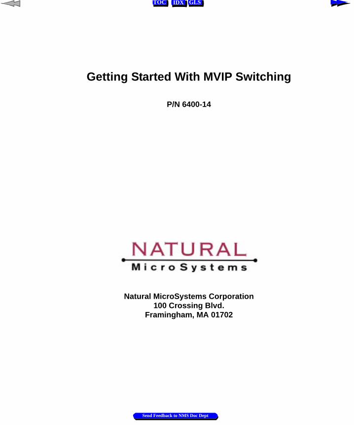
Revision History
Refer to the NMS web site (www.nmss.com) for product updates and for information about NMS support policies, warranty information, and service offerings.
Revision Release Date NotesP/N 6100 Original (Dana Lashway)1.0 Beta October, 1997 JLC, beta release1.1 January, 1998 JLC, product release1.2 October, 1998 SRG1.3 February, 1999 CYF, changes for Natural Access1.4 May, 2000 NBS, CT Access 3.0 and 4.0 This manual printed: June 12, 2000
Send Feedback to NMS Doc Dept
IDX GLSTOC
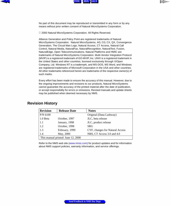
Table of Contents
1 What is Switching? . . . . . . . . . . . . . . . . . . . . . . . . . . . . . . . . . . . . . . . . . . . . . . . . 51.1 Overview . . . . . . . . . . . . . . . . . . . . . . . . . . . . . . . . . . . . . . . . . . . . . . . . . . . . 61.2 Introduction to Switching . . . . . . . . . . . . . . . . . . . . . . . . . . . . . . . . . . . . . . . . 71.3 Telephony Data . . . . . . . . . . . . . . . . . . . . . . . . . . . . . . . . . . . . . . . . . . . . . . . 8
1.3.1 Voice Data . . . . . . . . . . . . . . . . . . . . . . . . . . . . . . . . . . . . . . . . . . . . . 81.3.2 Signaling Data . . . . . . . . . . . . . . . . . . . . . . . . . . . . . . . . . . . . . . . . . 10
1.4 Making a Switch Connection . . . . . . . . . . . . . . . . . . . . . . . . . . . . . . . . . . . . 111.5 The Switch Block . . . . . . . . . . . . . . . . . . . . . . . . . . . . . . . . . . . . . . . . . . . . . 141.6 Switch Connections . . . . . . . . . . . . . . . . . . . . . . . . . . . . . . . . . . . . . . . . . . . 161.7 Switching Example. . . . . . . . . . . . . . . . . . . . . . . . . . . . . . . . . . . . . . . . . . . . 17
2 MVIP Switching . . . . . . . . . . . . . . . . . . . . . . . . . . . . . . . . . . . . . . . . . . . . . . . . . 212.1 Introduction . . . . . . . . . . . . . . . . . . . . . . . . . . . . . . . . . . . . . . . . . . . . . . . . . 222.2 MVIP Standards: MVIP-90, H-MVIP, MVIP-95, H.100 . . . . . . . . . . . . . . 232.3 MVIP Components. . . . . . . . . . . . . . . . . . . . . . . . . . . . . . . . . . . . . . . . . . . . 24
2.3.1 Network Interfaces . . . . . . . . . . . . . . . . . . . . . . . . . . . . . . . . . . . . . . 242.3.2 Processing Resources . . . . . . . . . . . . . . . . . . . . . . . . . . . . . . . . . . . . 252.3.3 MVIP Switch . . . . . . . . . . . . . . . . . . . . . . . . . . . . . . . . . . . . . . . . . . 25
2.4 Single-Board Switching . . . . . . . . . . . . . . . . . . . . . . . . . . . . . . . . . . . . . . . . 262.5 Telephony Bus Switching. . . . . . . . . . . . . . . . . . . . . . . . . . . . . . . . . . . . . . . 27
2.5.1 Telephony Bus Components. . . . . . . . . . . . . . . . . . . . . . . . . . . . . . . 282.5.2 Telephony Boards on the Bus. . . . . . . . . . . . . . . . . . . . . . . . . . . . . . 292.5.3 Telephony Bus Switch Connections. . . . . . . . . . . . . . . . . . . . . . . . . 31
2.6 Multi-Chassis Switching . . . . . . . . . . . . . . . . . . . . . . . . . . . . . . . . . . . . . . . 322.7 Switching Hierarchy. . . . . . . . . . . . . . . . . . . . . . . . . . . . . . . . . . . . . . . . . . . 34
3 The Switch Block Model . . . . . . . . . . . . . . . . . . . . . . . . . . . . . . . . . . . . . . . . . . . 353.1 Introduction . . . . . . . . . . . . . . . . . . . . . . . . . . . . . . . . . . . . . . . . . . . . . . . . . 363.2 MVIP-90 Switch Model . . . . . . . . . . . . . . . . . . . . . . . . . . . . . . . . . . . . . . . . 383.3 MVIP-90 Switching Examples. . . . . . . . . . . . . . . . . . . . . . . . . . . . . . . . . . . 49
3.3.1 Local DSP Resource to Network Interface. . . . . . . . . . . . . . . . . . . . 503.3.2 Connecting Network Interface to DSP Resources (1 switch). . . . . . 513.3.3 Connecting Network Interface to DSP Resources (2 switches) . . . . 523.3.4 Connecting Network Interface to Network Interface . . . . . . . . . . . . 53
Natural MicroSystems 3
Send Feedback to NMS Doc Dept

Table of Contents Getting Started With MVIP Switching
IDX GLSTOC
3.4 MVIP-95 Switch Model . . . . . . . . . . . . . . . . . . . . . . . . . . . . . . . . . . . . . . . . 543.5 MVIP-95 Switching Examples . . . . . . . . . . . . . . . . . . . . . . . . . . . . . . . . . . . 61
3.5.1 Local DSP Resource to Network Interface . . . . . . . . . . . . . . . . . . . . 623.5.2 Connecting Network Interface to DSP Resources (1 switch) . . . . . . 633.5.3 Connecting Network Interface to DSP Resources (2 switches) . . . . 643.5.4 Connecting Network Interface to Network Interface . . . . . . . . . . . . 65
4 MVIP Clocking . . . . . . . . . . . . . . . . . . . . . . . . . . . . . . . . . . . . . . . . . . . . . . . . . . . 674.1 Introduction . . . . . . . . . . . . . . . . . . . . . . . . . . . . . . . . . . . . . . . . . . . . . . . . . . 68
4.1.1 Telephony Bus Signals . . . . . . . . . . . . . . . . . . . . . . . . . . . . . . . . . . . 684.2 Single Chassis Clock Configuration . . . . . . . . . . . . . . . . . . . . . . . . . . . . . . . 69
4.2.1 H.100 Clock Configuration . . . . . . . . . . . . . . . . . . . . . . . . . . . . . . . . 704.2.2 MVIP-90 and H-MVIP Clock Configuration . . . . . . . . . . . . . . . . . . 72
4.3 Bus Clocking Fallback Behavior . . . . . . . . . . . . . . . . . . . . . . . . . . . . . . . . . . 734.3.1 H.100 Bus Primary Reference Trunk Failure . . . . . . . . . . . . . . . . . . 734.3.2 MVIP-90 and H-MVIP Bus Primary Reference Trunk Failure. . . . . 74
4.4 Multi-Chassis Clock Configuration. . . . . . . . . . . . . . . . . . . . . . . . . . . . . . . . 754.4.1 MC1 Bus and MVIP Bus Clock Interaction . . . . . . . . . . . . . . . . . . . 77
5 MVIP-90 and H.100 Bus Interaction . . . . . . . . . . . . . . . . . . . . . . . . . . . . . . . . . 795.1 Introduction . . . . . . . . . . . . . . . . . . . . . . . . . . . . . . . . . . . . . . . . . . . . . . . . . . 805.2 The MVIP Bus Adapter. . . . . . . . . . . . . . . . . . . . . . . . . . . . . . . . . . . . . . . . . 80
Appendix A Switching Examples . . . . . . . . . . . . . . . . . . . . . . . . . . . . . . . . . . . . . . . 83Introduction . . . . . . . . . . . . . . . . . . . . . . . . . . . . . . . . . . . . . . . . . . . . . . . . . . . . . . . 84Switching Example . . . . . . . . . . . . . . . . . . . . . . . . . . . . . . . . . . . . . . . . . . . . . . . . . 84
Appendix B Switch Implementation . . . . . . . . . . . . . . . . . . . . . . . . . . . . . . . . . . . . 87Introduction . . . . . . . . . . . . . . . . . . . . . . . . . . . . . . . . . . . . . . . . . . . . . . . . . . . . . . . 88HMIC Switch . . . . . . . . . . . . . . . . . . . . . . . . . . . . . . . . . . . . . . . . . . . . . . . . . . . . . 88
HMIC Switching Restrictions . . . . . . . . . . . . . . . . . . . . . . . . . . . . . . . . . . . 88FMIC Switch . . . . . . . . . . . . . . . . . . . . . . . . . . . . . . . . . . . . . . . . . . . . . . . . . . . . . . 89
FMIC Switching Restrictions . . . . . . . . . . . . . . . . . . . . . . . . . . . . . . . . . . . 89Digital Crosspoint Switches . . . . . . . . . . . . . . . . . . . . . . . . . . . . . . . . . . . . . . . . . . 91
4 Natural MicroSystems
Send Feedback to NMS Doc Dept
IDX GLSTOC
Chapter 1
What is Switching?
1.1 Overview 6
1.2 Introduction to Switching 7
1.3 Telephony Data 81.3.1 Voice Data 81.3.2 Signaling Data 10
1.4 Making a Switch Connection 11
1.5 The Switch Block 14
1.6 Switch Connections 16
1.7 Switching Example 17
Natural MicroSystems 5
Send Feedback to NMS Doc Dept
Chapter 1 What is Switching? Getting Started With MVIP Switching
IDX GLSTOC
1.1 Overview
In 1990, a consortium of PC telephony leaders, including Natural MicroSystems and seven other companies, established an industry standard telephony bus. The Multi-Vendor Integration Protocol (MVIP) bus is the most widely adopted bus in the PC telephony industry and continues to evolve.
For more information on the bus specifications, refer to the following manuals:
For GO-MVIP information, please contact:
GO-MVIP, Inc. 3220 N Street, NW, Suite 360, Washington, DC 20007
Tel: 800-NOW-MVIP (US and Canada)Tel: 903-769-3717; Fax: 903-769-3818
Email: [email protected]
For ECTF information, please contact:
ECTF39355 California Street, Suite 307, Fremont, CA 94538
Tel: 501-608-5915Fax: 510-608-5917Email:[email protected]
This manual... Provides...
ECTF: H.100 Revision 1.0 Hardware Compatibility Specification: CT Bus
Information about the H.100 bus, available from ECTF.
ECTF: H.110 Revision 1.0 Hardware Compatibility Specification: CT Bus
Information about the H.110 bus, available from ECTF.
MVIP-95 Device Driver Standard Information about MVIP-95, available from GO-MVIP.
H-MVIP Standard Information about H-MVIP, available from GO-MVIP.
MVIP-90 Standard Information about MVIP-90, available from GO-MVIP.
Go-MVIP: MC1 Multi-Chassis MVIP Standard
The specification for MC1 operation
6 Natural MicroSystems
Send Feedback to NMS Doc Dept
Getting Started With MVIP Switching Introduction to Switching
IDX GLSTOC
1.2 Introduction to Switching
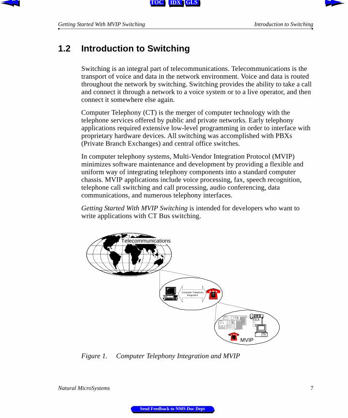
Switching is an integral part of telecommunications. Telecommunications is the transport of voice and data in the network environment. Voice and data is routed throughout the network by switching. Switching provides the ability to take a call and connect it through a network to a voice system or to a live operator, and then connect it somewhere else again.
Computer Telephony (CT) is the merger of computer technology with the telephone services offered by public and private networks. Early telephony applications required extensive low-level programming in order to interface with proprietary hardware devices. All switching was accomplished with PBXs (Private Branch Exchanges) and central office switches.
In computer telephony systems, Multi-Vendor Integration Protocol (MVIP) minimizes software maintenance and development by providing a flexible and uniform way of integrating telephony components into a standard computer chassis. MVIP applications include voice processing, fax, speech recognition, telephone call switching and call processing, audio conferencing, data communications, and numerous telephony interfaces.
Getting Started With MVIP Switching is intended for developers who want to write applications with CT Bus switching.
Figure 1. Computer Telephony Integration and MVIP
Telecommunications
Computer TelephonyIntegration
MVIP
Natural MicroSystems 7
Send Feedback to NMS Doc Dept
Chapter 1 What is Switching? Getting Started With MVIP Switching
IDX GLSTOC
st if
alog
t a
ht
1.3 Telephony Data
In a typical telephone call, two types of information are exchanged: voice data and signaling data.
1.3.1 Voice Data
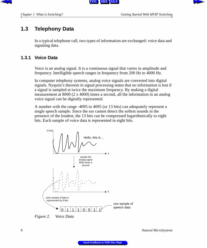
Voice is an analog signal. It is a continuous signal that varies in amplitude and frequency. Intelligible speech ranges in frequency from 200 Hz to 4000 Hz.
In computer telephony systems, analog voice signals are converted into digital signals. Nyquist’s theorem in signal processing states that no information is loa signal is sampled at twice the maximum frequency. By making a digital measurement at 8000 (2 x 4000) times a second, all the information in an anvoice signal can be digitally represented.
A number with the range -4095 to 4095 (or 13 bits) can adequately represensingle speech sample. Since the ear cannot detect the softest sounds in the presence of the loudest, the 13 bits can be compressed logarithmically to eigbits. Each sample of voice data is represented in eight bits.
Figure 2. Voice Data
sample theanalog signal8000 times a
second
each sample of data isrepresented by 8 bits
0 1 1 1 0 0 1 1
one sample ofspeech data
t
t
Hello, this is ...
4 KHz
8 Natural MicroSystems
Send Feedback to NMS Doc Dept
Getting Started With MVIP Switching Voice Data
IDX GLSTOC
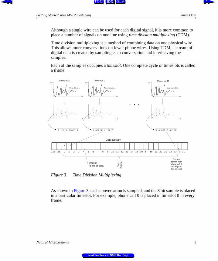
Although a single wire can be used for each digital signal, it is more common to place a number of signals on one line using time division multiplexing (TDM).
Time division multiplexing is a method of combining data on one physical wire. This allows more conversations on fewer phone wires. Using TDM, a stream of digital data is created by sampling each conversation and interleaving the samples.
Each of the samples occupies a timeslot. One complete cycle of timeslots is called a frame.
Figure 3. Time Division Multiplexing
As shown in Figure 3, each conversation is sampled, and the 8 bit sample is placed in a particular timeslot. For example, phone call 0 is placed in timeslot 0 in every frame.
0 1 1 1 0 0 1 1
t
t
Hello, this is ...
4 KHz
0
One
Fra
metimeslot
(8 bits of data)
Data Stream
0 1 2 3 4 5 6 7 8 9 10 11 12 13 14 15 16 17 18 19 20 21 22 23 1...23...22
0 0 0 1 1 1 0 0
t
t
Fine, how are ...
4 KHz
1 0 0 0 0 0 1 1
t
t
Just wanted to ...
4 KHz
Phone call 0 Phone call 1 Phone call 23
The nextsample fromphone call 0would go inthis timeslot
Natural MicroSystems 9
Send Feedback to NMS Doc Dept
Chapter 1 What is Switching? Getting Started With MVIP Switching
IDX GLSTOC
In TDM, there is a start-of-frame signal. Each device connected to the data stream counts from the start-of-frame signal to determine when to place a sample in a particular timeslot or when to read data from a particular timeslot.
On a digital phone path, each second of data is divided into 8000 (2 x 4000) frames. Each frame is 125 microseconds long and is divided into 8-bit timeslots, one timeslot for each connection.
The rate at which the frame is sampled determines the number of timeslots in each frame. The sampling rate (or bus speed) is determined by the system standard. For example, a T1 system has 24 timeslots per frame; a CEPT E1 system has 32 timeslots per frame.
1.3.2 Signaling Data
Along with voice information, streams of data carry signaling information. Signaling is used to control switch connections or to indicate the status of a call.
For example, the network informs the local device when an incoming call is arriving (ringing), and the device informs the network that the call is accepted (answered or goes off-hook).
In common channel signaling (CCS), signaling information is carried on a single, separate communications path. In channel associated signaling (CAS), the signaling is carried on, or along with, the voice information.
Some examples of signaling methods are:
Æ An analog line uses high voltage ringing signals and current flow for channel associated signaling.
Æ A T1 system uses the least significant bit of every sixth sample in the voice path for channel associated signaling.
Æ A CEPT E1 system has channel associated signaling bits packed into certain timeslots.
Æ An ISDN primary rate systems uses a timeslot to carry packets of common channel signaling messages.
10 Natural MicroSystems
Send Feedback to NMS Doc Dept
Getting Started With MVIP Switching Making a Switch Connection
IDX GLSTOC
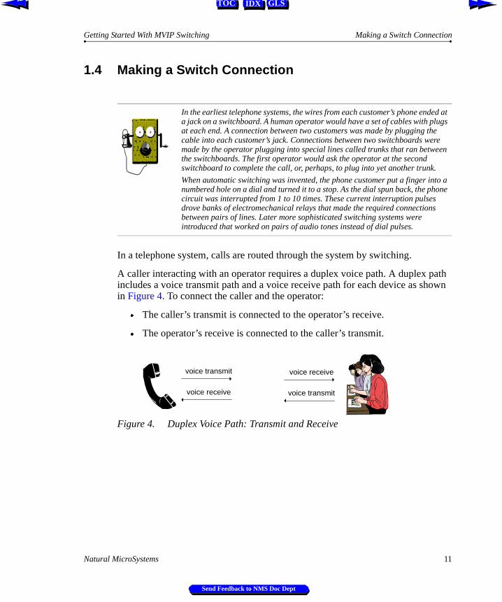
1.4 Making a Switch Connection
In a telephone system, calls are routed through the system by switching.
A caller interacting with an operator requires a duplex voice path. A duplex path includes a voice transmit path and a voice receive path for each device as shown in Figure 4. To connect the caller and the operator:
Æ The caller’s transmit is connected to the operator’s receive.
Æ The operator’s receive is connected to the caller’s transmit.
Figure 4. Duplex Voice Path: Transmit and Receive
In the earliest telephone systems, the wires from each customer’s phone ended at a jack on a switchboard. A human operator would have a set of cables with plugs at each end. A connection between two customers was made by plugging the cable into each customer’s jack. Connections between two switchboards were made by the operator plugging into special lines called trunks that ran between the switchboards. The first operator would ask the operator at the second switchboard to complete the call, or, perhaps, to plug into yet another trunk.
When automatic switching was invented, the phone customer put a finger into a numbered hole on a dial and turned it to a stop. As the dial spun back, the phone circuit was interrupted from 1 to 10 times. These current interruption pulses drove banks of electromechanical relays that made the required connections between pairs of lines. Later more sophisticated switching systems were introduced that worked on pairs of audio tones instead of dial pulses.
voice transmit
voice receive
voice receive
voice transmit
Natural MicroSystems 11
Send Feedback to NMS Doc Dept
Chapter 1 What is Switching? Getting Started With MVIP Switching
IDX GLSTOC
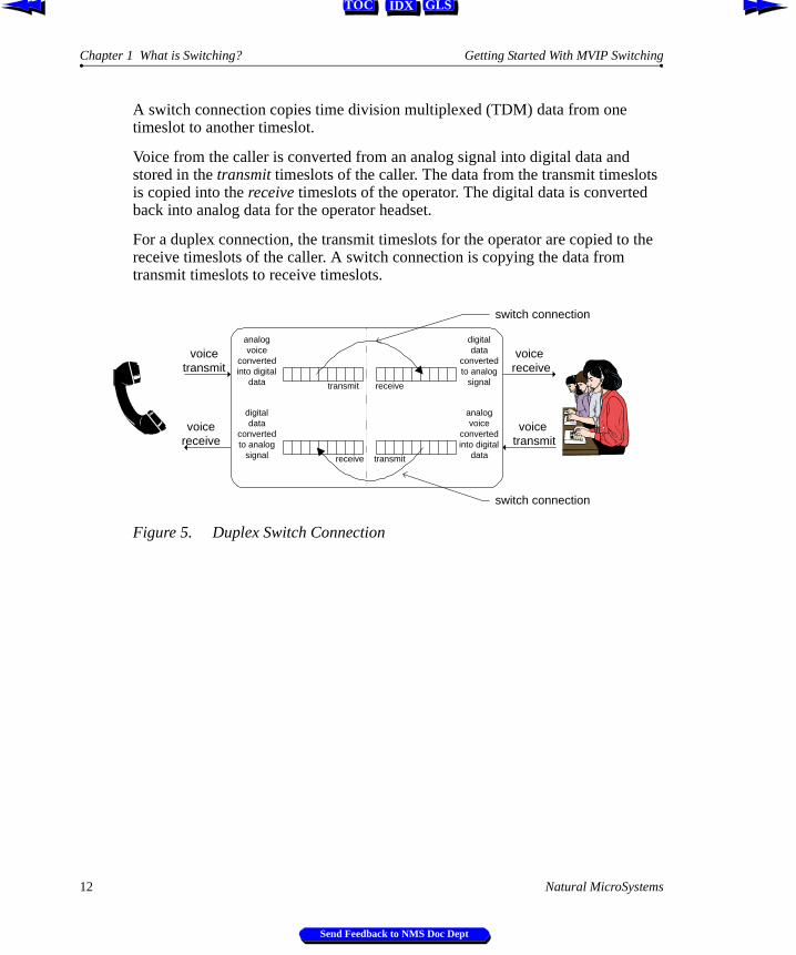
A switch connection copies time division multiplexed (TDM) data from one timeslot to another timeslot.
Voice from the caller is converted from an analog signal into digital data and stored in the transmit timeslots of the caller. The data from the transmit timeslots is copied into the receive timeslots of the operator. The digital data is converted back into analog data for the operator headset.
For a duplex connection, the transmit timeslots for the operator are copied to the receive timeslots of the caller. A switch connection is copying the data from transmit timeslots to receive timeslots.
Figure 5. Duplex Switch Connection
voicetransmit
voicereceive
voice receive
voice transmit
analogvoice
convertedinto digital
data
digitaldata
convertedto analog
signal
digitaldata
convertedto analog
signal
analogvoice
convertedinto digital
data
transmit
transmitreceive
receive
switch connection
switch connection
12 Natural MicroSystems
Send Feedback to NMS Doc Dept
Getting Started With MVIP Switching Making a Switch Connection
IDX GLSTOC
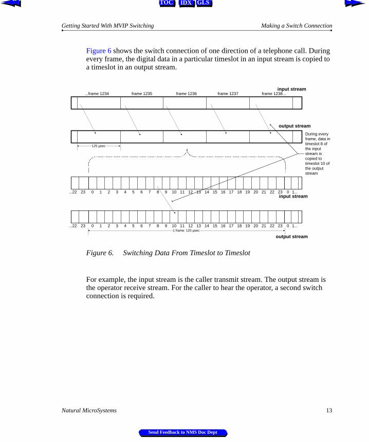
Figure 6 shows the switch connection of one direction of a telephone call. During every frame, the digital data in a particular timeslot in an input stream is copied to a timeslot in an output stream.
Figure 6. Switching Data From Timeslot to Timeslot
For example, the input stream is the caller transmit stream. The output stream is the operator receive stream. For the caller to hear the operator, a second switch connection is required.
00 1 2 3 4 5 6 7 8 9 10 11 12 13 14 15 16 17 18 19 20 21 22 23 1...23...22
00 1 2 3 4 5 6 7 8 9 10 11 12 13 14 15 16 17 18 19 20 21 22 23 1...23...22
input stream
output stream
output stream
125 µsec
input stream...frame 1234 frame 1235 frame 1236 frame 1238...frame 1237
1 frame: 125 µsec
During everyframe, data intimeslot 8 ofthe inputstream iscopied totimeslot 10 ofthe outputstream
Natural MicroSystems 13
Send Feedback to NMS Doc Dept
Chapter 1 What is Switching? Getting Started With MVIP Switching
IDX GLSTOC
1.5 The Switch Block
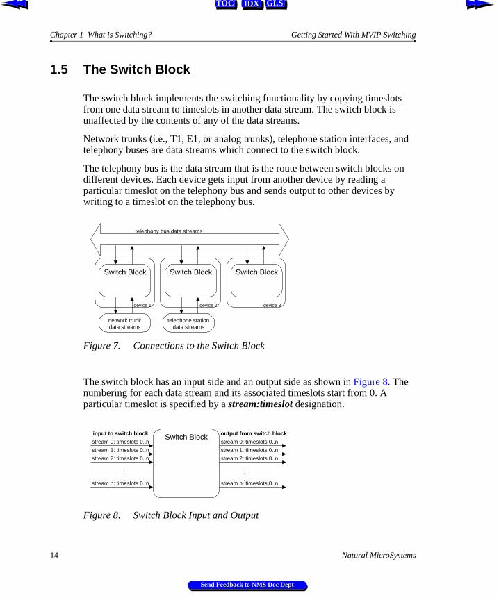
The switch block implements the switching functionality by copying timeslots from one data stream to timeslots in another data stream. The switch block is unaffected by the contents of any of the data streams.
Network trunks (i.e., T1, E1, or analog trunks), telephone station interfaces, and telephony buses are data streams which connect to the switch block.
The telephony bus is the data stream that is the route between switch blocks on different devices. Each device gets input from another device by reading a particular timeslot on the telephony bus and sends output to other devices by writing to a timeslot on the telephony bus.
Figure 7. Connections to the Switch Block
The switch block has an input side and an output side as shown in Figure 8. The numbering for each data stream and its associated timeslots start from 0. A particular timeslot is specified by a stream:timeslot designation.
Figure 8. Switch Block Input and Output
telephony bus data streams
Switch Block Switch Block Switch Block
network trunkdata streams
telephone stationdata streams
device 1 device 2 device 3
Switch Blockstream 0: timeslots 0..n
stream 1: timeslots 0..n
stream 2: timeslots 0..n
stream n: timeslots 0..n
.
.
.
.
.
.
input to switch block output from switch block
stream 0: timeslots 0..n
stream 1: timeslots 0..n
stream 2: timeslots 0..n
stream n: timeslots 0..n
14 Natural MicroSystems
Send Feedback to NMS Doc Dept
Getting Started With MVIP Switching The Switch Block
IDX GLSTOC
d
ng
lot,
ck up lar
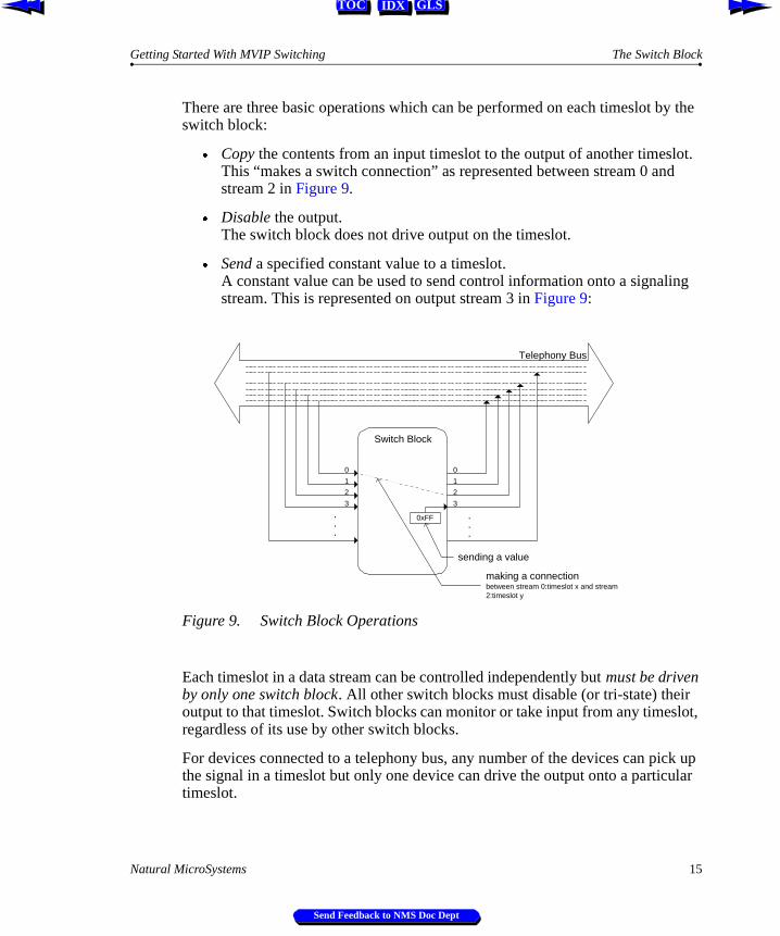
There are three basic operations which can be performed on each timeslot by the switch block:
Æ Copy the contents from an input timeslot to the output of another timeslot. This “makes a switch connection” as represented between stream 0 anstream 2 in Figure 9.
Æ Disable the output. The switch block does not drive output on the timeslot.
Æ Send a specified constant value to a timeslot.A constant value can be used to send control information onto a signalistream. This is represented on output stream 3 in Figure 9:
Figure 9. Switch Block Operations
Each timeslot in a data stream can be controlled independently but must be driven by only one switch block. All other switch blocks must disable (or tri-state) theiroutput to that timeslot. Switch blocks can monitor or take input from any timesregardless of its use by other switch blocks.
For devices connected to a telephony bus, any number of the devices can pithe signal in a timeslot but only one device can drive the output onto a particutimeslot.
Switch Block
.
.
.
.
.
.
0 0
11
2 2
3 3
0xFF
sending a value
making a connectionbetween stream 0:timeslot x and stream2:timeslot y
Telephony Bus
Natural MicroSystems 15
Send Feedback to NMS Doc Dept
Chapter 1 What is Switching? Getting Started With MVIP Switching
IDX GLSTOC
1.6 Switch Connections
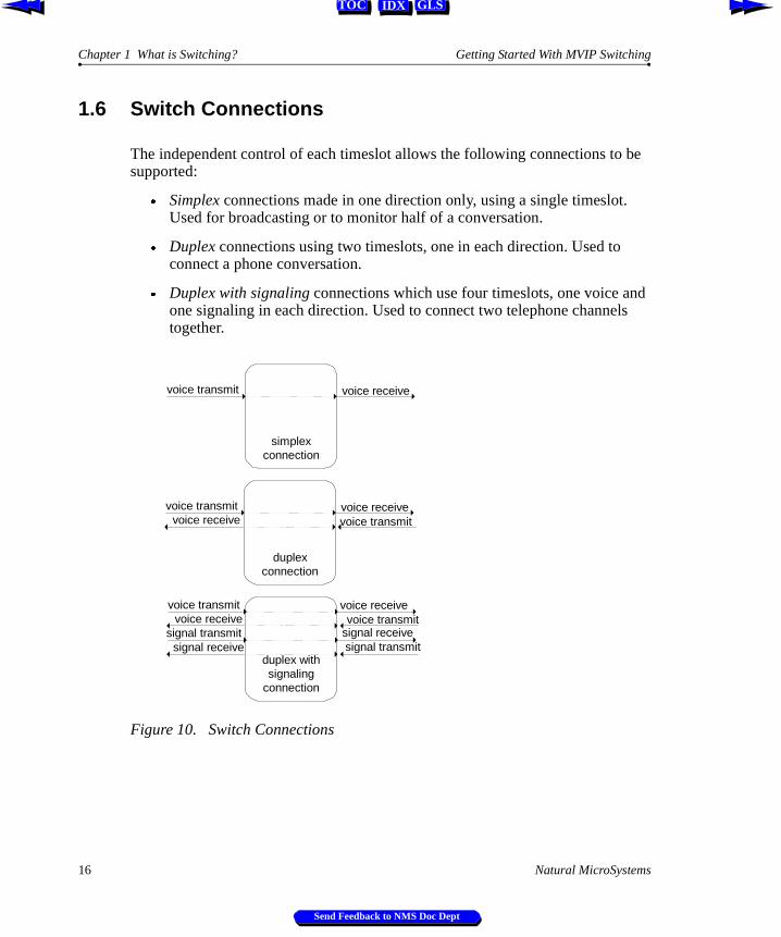
The independent control of each timeslot allows the following connections to be supported:
Æ Simplex connections made in one direction only, using a single timeslot. Used for broadcasting or to monitor half of a conversation.
Æ Duplex connections using two timeslots, one in each direction. Used to connect a phone conversation.
Æ Duplex with signaling connections which use four timeslots, one voice and one signaling in each direction. Used to connect two telephone channels together.
Figure 10. Switch Connections
simplexconnection
voice transmit
voice receive
voice receive
voice transmit
duplexconnection
voice transmit voice receive
voice receive voice transmit
duplex withsignaling
connection
voice transmit voice receive
signal receive signal transmitsignal transmit signal receive
16 Natural MicroSystems
Send Feedback to NMS Doc Dept
Getting Started With MVIP Switching Switching Example
IDX GLSTOC
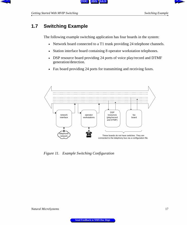
1.7 Switching Example
The following example switching application has four boards in the system:
Æ Network board connected to a T1 trunk providing 24 telephone channels.
Æ Station interface board containing 8 operator workstation telephones.
Æ DSP resource board providing 24 ports of voice play/record and DTMF generation/detection.
Æ Fax board providing 24 ports for transmitting and receiving faxes.
Figure 11. Example Switching Configuration
operatorworkstations
networkinterface
DSPresources
(play/recordand DTMF)
faxboard
telephonenetwork These boards do not have switches. They are
connected to the telephony bus via a configuration file.
Natural MicroSystems 17
Send Feedback to NMS Doc Dept

Chapter 1 What is Switching? Getting Started With MVIP Switching
IDX GLSTOC
ade
A typical incoming call would be serviced in the following steps:
1. When a call is received on one of the T1 channels, a switch connection is made to connect the call to a DSP resource which plays a voice prompt. The caller is instructed to enter a digit to choose a service. The DSP resources are used to detect the digit entered by the caller.
Figure 12. Connecting to DSP Resources
2. The caller presses “0” to speak to an operator. Switch connections are mto connect the caller to an available operator workstation.
Figure 13. Connecting to an Operator Station
operatorworkstations
networkinterface
DSPresources
(play/recordand DTMF)
faxboard
telephonenetwork
Switch connection fromtelephone channel onT1 trunk to telephonybus where DSPresources are located
operatorworkstations
networkinterface
DSPresources
(play/recordand DTMF)
faxboard
telephonenetwork
Switch connection toconnect operatorworkstation totelephony bus
Switch connection toconnect T1 channel totelephony bus (whereoperator workstation isconnected)
18 Natural MicroSystems
Send Feedback to NMS Doc Dept
Getting Started With MVIP Switching Switching Example
IDX GLSTOC
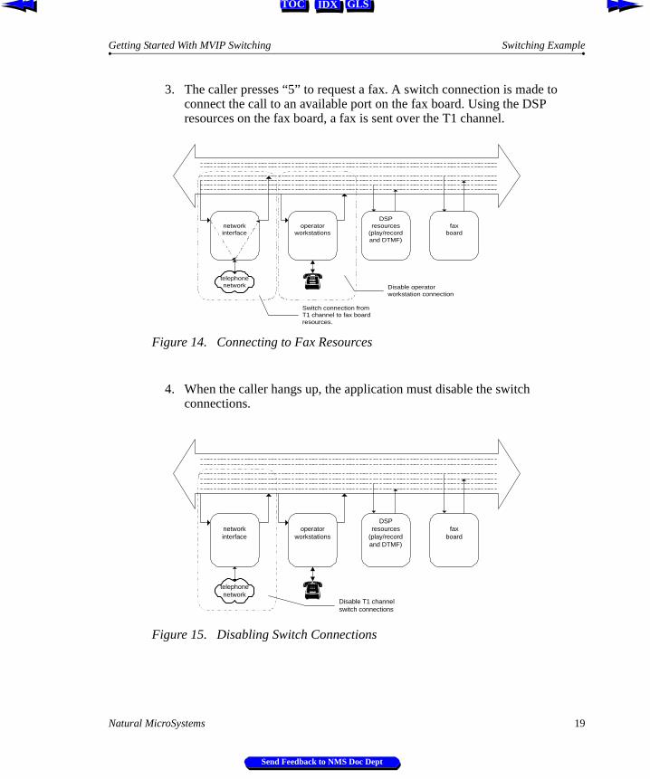
3. The caller presses “5” to request a fax. A switch connection is made to connect the call to an available port on the fax board. Using the DSP resources on the fax board, a fax is sent over the T1 channel.
Figure 14. Connecting to Fax Resources
4. When the caller hangs up, the application must disable the switch connections.
Figure 15. Disabling Switch Connections
operatorworkstations
networkinterface
DSPresources
(play/recordand DTMF)
faxboard
telephonenetwork
Switch connection fromT1 channel to fax boardresources.
Disable operatorworkstation connection
operatorworkstations
networkinterface
DSPresources
(play/recordand DTMF)
faxboard
telephonenetwork
Disable T1 channelswitch connections
Natural MicroSystems 19
Send Feedback to NMS Doc Dept

Chapter 1 What is Switching? Getting Started With MVIP Switching
IDX GLSTOC
20 Natural MicroSystems
Send Feedback to NMS Doc Dept
IDX GLSTOC
Chapter 2
MVIP Switching
2.1 Introduction 22
2.2 MVIP Standards: MVIP-90, H-MVIP, MVIP-95, H.100 23
2.3 MVIP Components 242.3.1 Network Interfaces 242.3.2 Processing Resources 252.3.3 MVIP Switch 25
2.4 Single-Board Switching 26
2.5 Telephony Bus Switching 272.5.1 Telephony Bus Components 282.5.2 Telephony Boards on the Bus 292.5.3 Telephony Bus Switch Connections 31
2.6 Multi-Chassis Switching 32
2.7 Switching Hierarchy 34
Natural MicroSystems 21
Send Feedback to NMS Doc Dept
Chapter 2 MVIP Switching Getting Started With MVIP Switching
IDX GLSTOC
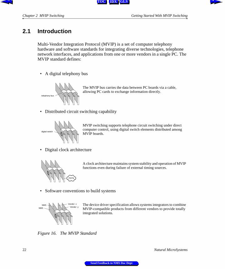
2.1 Introduction
Multi-Vendor Integration Protocol (MVIP) is a set of computer telephony hardware and software standards for integrating diverse technologies, telephone network interfaces, and applications from one or more vendors in a single PC. The MVIP standard defines:
Figure 16. The MVIP Standard
• A digital telephony bus
The MVIP bus carries the data between PC boards via a cable, allowing PC cards to exchange information directly.
• Distributed circuit switching capability
MVIP switching supports telephone circuit switching under direct computer control, using digital switch elements distributed among MVIP boards.
• Digital clock architecture
A clock architecture maintains system stability and operation of MVIP functions even during failure of external timing sources.
• Software conventions to build systems
The device driver specification allows systems integrators to combine MVIP-compatible products from different vendors to provide totally integrated solutions.
telephony bus
digital switch
PSTN
NMS
NMS Vendor x
Vendor y
22 Natural MicroSystems
Send Feedback to NMS Doc Dept
Getting Started With MVIP Switching MVIP Standards: MVIP-90, H-MVIP, MVIP-95, H.100
IDX GLSTOC
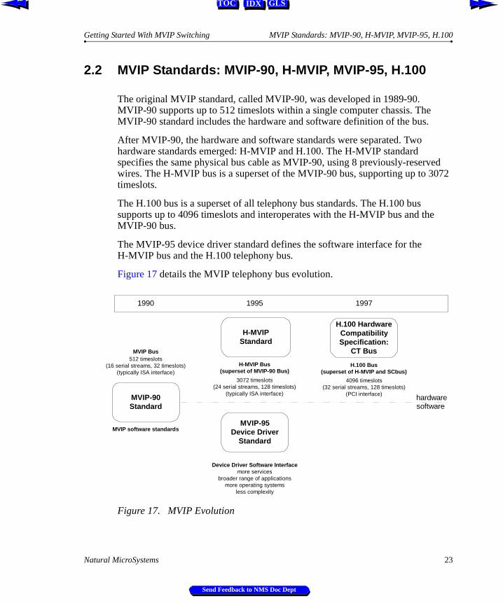
2.2 MVIP Standards: MVIP-90, H-MVIP, MVIP-95, H.100
The original MVIP standard, called MVIP-90, was developed in 1989-90.MVIP-90 supports up to 512 timeslots within a single computer chassis. The MVIP-90 standard includes the hardware and software definition of the bus.
After MVIP-90, the hardware and software standards were separated. Two hardware standards emerged: H-MVIP and H.100. The H-MVIP standard specifies the same physical bus cable as MVIP-90, using 8 previously-reserved wires. The H-MVIP bus is a superset of the MVIP-90 bus, supporting up to 3072 timeslots.
The H.100 bus is a superset of all telephony bus standards. The H.100 bus supports up to 4096 timeslots and interoperates with the H-MVIP bus and the MVIP-90 bus.
The MVIP-95 device driver standard defines the software interface for the H-MVIP bus and the H.100 telephony bus.
Figure 17 details the MVIP telephony bus evolution.
Figure 17. MVIP Evolution
H-MVIPStandard
MVIP-95Device Driver
Standard
H.100 HardwareCompatibilitySpecification:
CT Bus512 timeslots
(16 serial streams, 32 timeslots)(typically ISA interface)
3072 timeslots(24 serial streams, 128 timeslots)
(typically ISA interface)
4096 timeslots(32 serial streams, 128 timeslots)
(PCI interface)
more servicesbroader range of applications
more operating systemsless complexity
MVIP software standards
H-MVIP Bus(superset of MVIP-90 Bus)
H.100 Bus(superset of H-MVIP and SCbus)
Device Driver Software Interface
1990
MVIP-90Standard
hardwaresoftware
MVIP Bus
1995 1997
Natural MicroSystems 23
Send Feedback to NMS Doc Dept
Chapter 2 MVIP Switching Getting Started With MVIP Switching
IDX GLSTOC
2.3 MVIP Components
An MVIP system has three elements:
Æ Network interfacesÆ Processing resourcesÆ MVIP switches
2.3.1 Network Interfaces
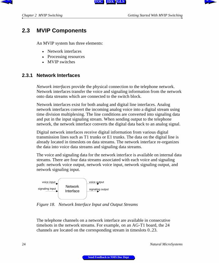
Network interfaces provide the physical connection to the telephone network. Network interfaces transfer the voice and signaling information from the network onto data streams which are connected to the switch block.
Network interfaces exist for both analog and digital line interfaces. Analog network interfaces convert the incoming analog voice into a digital stream using time division multiplexing. The line conditions are converted into signaling data and put in the input signaling stream. When sending output to the telephone network, the network interface converts the digital data back to an analog signal.
Digital network interfaces receive digital information from various digital transmission lines such as T1 trunks or E1 trunks. The data on the digital line is already located in timeslots on data streams. The network interface re-organizes the data into voice data streams and signaling data streams.
The voice and signaling data for the network interface is available on internal data streams. There are four data streams associated with each voice and signaling path: network voice output, network voice input, network signaling output, and network signaling input.
Figure 18. Network Interface Input and Output Streams
The telephone channels on a network interface are available in consecutive timelsots in the network streams. For example, on an AG-T1 board, the 24 channels are located on the corresponding stream in timeslots 0..23.
NetworkInterface
voice input
signaling input signaling output
voice output
24 Natural MicroSystems
Send Feedback to NMS Doc Dept
Getting Started With MVIP Switching Processing Resources
IDX GLSTOC
ing ork
ot
MVIP
2.3.2 Processing Resources
Processing resources such as digital signal processors (DSP) perform functions such as monitoring the progress of a telephone call, digitally recording and playing back speech, or transmitting and receiving fax messages. DSP resources provide the core functionality in a system by processing input received from the telephone network and by providing output to be sent to the telephone network.
The voice and signaling information for the DSP resource is available on internal data streams. There are four data streams associated with each voice and signaling path: DSP voice output, DSP voice input, DSP signaling output, and DSP signaling input.
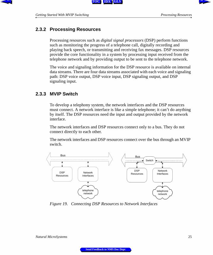
2.3.3 MVIP Switch
To develop a telephony system, the network interfaces and the DSP resources must connect. A network interface is like a simple telephone; it can’t do anythby itself. The DSP resources need the input and output provided by the netwinterface.
The network interfaces and DSP resources connect only to a bus. They do nconnect directly to each other.
The network interfaces and DSP resources connect over the bus through an switch.
Figure 19. Connecting DSP Resources to Network Interfaces
DSPResources
NetworkInterfaces
telephonenetwork
Bus
DSPResources
NetworkInterfaces
telephonenetwork
BusSwitch
Natural MicroSystems 25
Send Feedback to NMS Doc Dept
Chapter 2 MVIP Switching Getting Started With MVIP Switching
IDX GLSTOC
2.4 Single-Board Switching
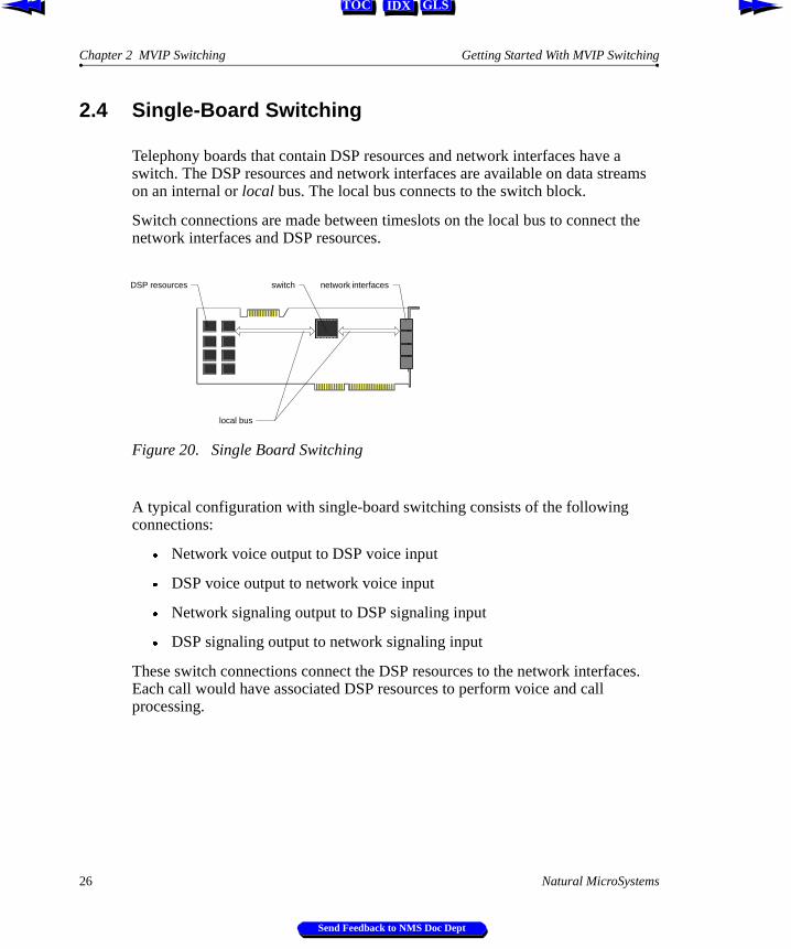
Telephony boards that contain DSP resources and network interfaces have a switch. The DSP resources and network interfaces are available on data streams on an internal or local bus. The local bus connects to the switch block.
Switch connections are made between timeslots on the local bus to connect the network interfaces and DSP resources.
Figure 20. Single Board Switching
A typical configuration with single-board switching consists of the following connections:
Æ Network voice output to DSP voice input
Æ DSP voice output to network voice input
Æ Network signaling output to DSP signaling input
Æ DSP signaling output to network signaling input
These switch connections connect the DSP resources to the network interfaces. Each call would have associated DSP resources to perform voice and call processing.
DSP resources network interfacesswitch
local bus
26 Natural MicroSystems
Send Feedback to NMS Doc Dept
Getting Started With MVIP Switching Telephony Bus Switching
IDX GLSTOC
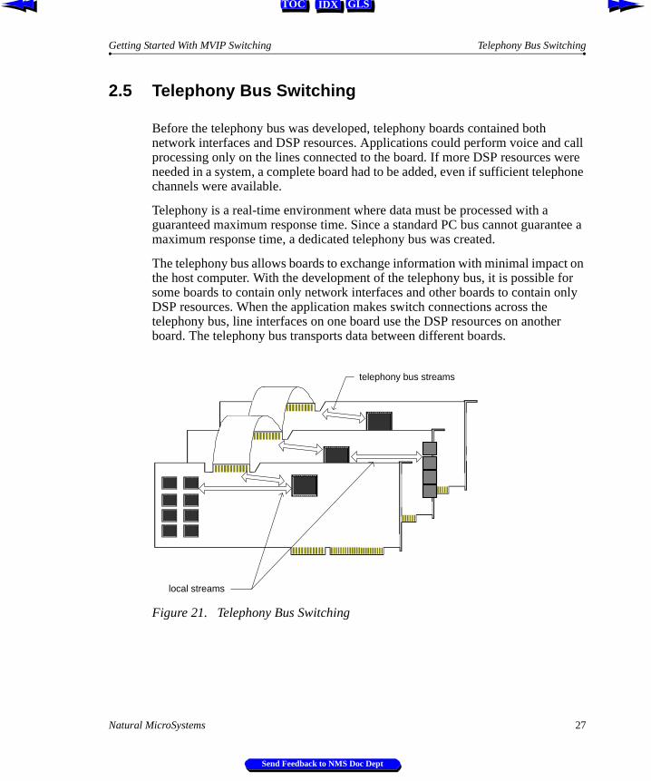
2.5 Telephony Bus Switching
Before the telephony bus was developed, telephony boards contained both network interfaces and DSP resources. Applications could perform voice and call processing only on the lines connected to the board. If more DSP resources were needed in a system, a complete board had to be added, even if sufficient telephone channels were available.
Telephony is a real-time environment where data must be processed with a guaranteed maximum response time. Since a standard PC bus cannot guarantee a maximum response time, a dedicated telephony bus was created.
The telephony bus allows boards to exchange information with minimal impact on the host computer. With the development of the telephony bus, it is possible for some boards to contain only network interfaces and other boards to contain only DSP resources. When the application makes switch connections across the telephony bus, line interfaces on one board use the DSP resources on another board. The telephony bus transports data between different boards.
Figure 21. Telephony Bus Switching
local streams
telephony bus streams
Natural MicroSystems 27
Send Feedback to NMS Doc Dept
Chapter 2 MVIP Switching Getting Started With MVIP Switching
IDX GLSTOC
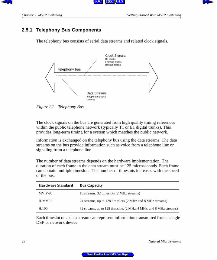
2.5.1 Telephony Bus Components
The telephony bus consists of serial data streams and related clock signals.
Figure 22. Telephony Bus
The clock signals on the bus are generated from high quality timing references within the public telephone network (typically T1 or E1 digital trunks). This provides long-term timing for a system which matches the public network.
Information is exchanged on the telephony bus using the data streams. The data streams on the bus provide information such as voice from a telephone line or signaling from a telephone line.
The number of data streams depends on the hardware implementation. The duration of each frame in the data stream must be 125 microseconds. Each frame can contain multiple timeslots. The number of timeslots increases with the speed of the bus.
Each timeslot on a data stream can represent information transmitted from a single DSP or network device.
Hardware Standard Bus Capacity
MVIP-90 16 streams, 32 timeslots (2 MHz streams)
H-MVIP 24 streams, up to 128 timeslots (2 MHz and 8 MHz streams)
H.100 32 streams, up to 128 timeslots (2 MHz, 4 MHz, and 8 MHz streams)
telephony bus
Data Streams:independant serialstreams
Clock Signals:Bit clocksFraming clocksBackup clocks
28 Natural MicroSystems
Send Feedback to NMS Doc Dept
Getting Started With MVIP Switching Telephony Boards on the Bus
IDX GLSTOC
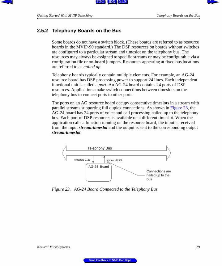
2.5.2 Telephony Boards on the Bus
Some boards do not have a switch block. (These boards are referred to as resource boards in the MVIP-90 standard.) The DSP resources on boards without switches are configured to a particular stream and timeslot on the telephony bus. The resources may always be assigned to specific streams or may be configurable via a configuration file or on-board jumpers. Resources appearing at fixed bus locations are referred to as nailed up.
Telephony boards typically contain multiple elements. For example, an AG-24 resource board has DSP processing power to support 24 lines. Each independent functional unit is called a port. An AG-24 board contains 24 ports of DSP resources. Applications make switch connections between timeslots on the telephony bus to connect ports to other ports.
The ports on an AG resource board occupy consecutive timeslots in a stream with parallel streams supporting full duplex connections. As shown in Figure 23, the AG-24 board has 24 ports of voice and call processing nailed up to the telephony bus. Each port of DSP resources is available on a different timeslot. When the application calls a function running on the resource board, the input is received from the input stream:timeslot and the output is sent to the corresponding output stream:timeslot.
Figure 23. AG-24 Board Connected to the Telephony Bus
AG-24 Board
Telephony Bus
timeslots 0..23timeslots 0..23
Connections arenailed up to thebus
Natural MicroSystems 29
Send Feedback to NMS Doc Dept

Chapter 2 MVIP Switching Getting Started With MVIP Switching
IDX GLSTOC
Boards containing network interfaces have a switch block. These boards have access to voice and signaling data from the telephone network and may also contain local DSP resources. For example, an AG-T1 board connects to a T1 trunk and has 24 ports of DSP resources.
Boards which contain a switch do not have nailed up bus connections. The network interfaces and DSP resources are available on a local bus which is connected to the switch block. Network interfaces and local resources are connected to other boards in the system by making switch connections across the telephony bus.
Figure 24. Network Board Connected to the Telephony Bus
Network Board
telephonenetwork
Telephony Bus
telephony bus
Localinterfaces &resources
30 Natural MicroSystems
Send Feedback to NMS Doc Dept
Getting Started With MVIP Switching Telephony Bus Switch Connections
IDX GLSTOC
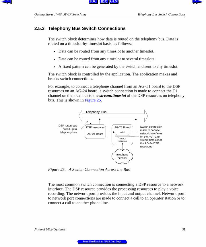
2.5.3 Telephony Bus Switch Connections
The switch block determines how data is routed on the telephony bus. Data is routed on a timeslot-by-timeslot basis, as follows:
Æ Data can be routed from any timeslot to another timeslot.
Æ Data can be routed from any timeslot to several timeslots.
Æ A fixed pattern can be generated by the switch and sent to any timeslot.
The switch block is controlled by the application. The application makes and breaks switch connections.
For example, to connect a telephone channel from an AG-T1 board to the DSP resources on an AG-24 board, a switch connection is made to connect the T1 channel on the local bus to the stream:timeslot of the DSP resources on telephony bus. This is shown in Figure 25.
Figure 25. A Switch Connection Across the Bus
The most common switch connection is connecting a DSP resource to a network interface. The DSP resource provides the processing resources to play a voice recording. The network port provides the input and output channel. Network port to network port connections are made to connect a call to an operator station or to connect a call to another phone line.
DSP resources
AG-24 Board
AG-T1 Board
telephonenetwork
Telephony Bus
switch
localresources
DSP resourcesnailed up to
telephony bus
Switch connectionmade to connectnetwork interfaceson the AG-T1 tostream:timeslot ofthe AG-24 DSPresources
Natural MicroSystems 31
Send Feedback to NMS Doc Dept
Chapter 2 MVIP Switching Getting Started With MVIP Switching
IDX GLSTOC
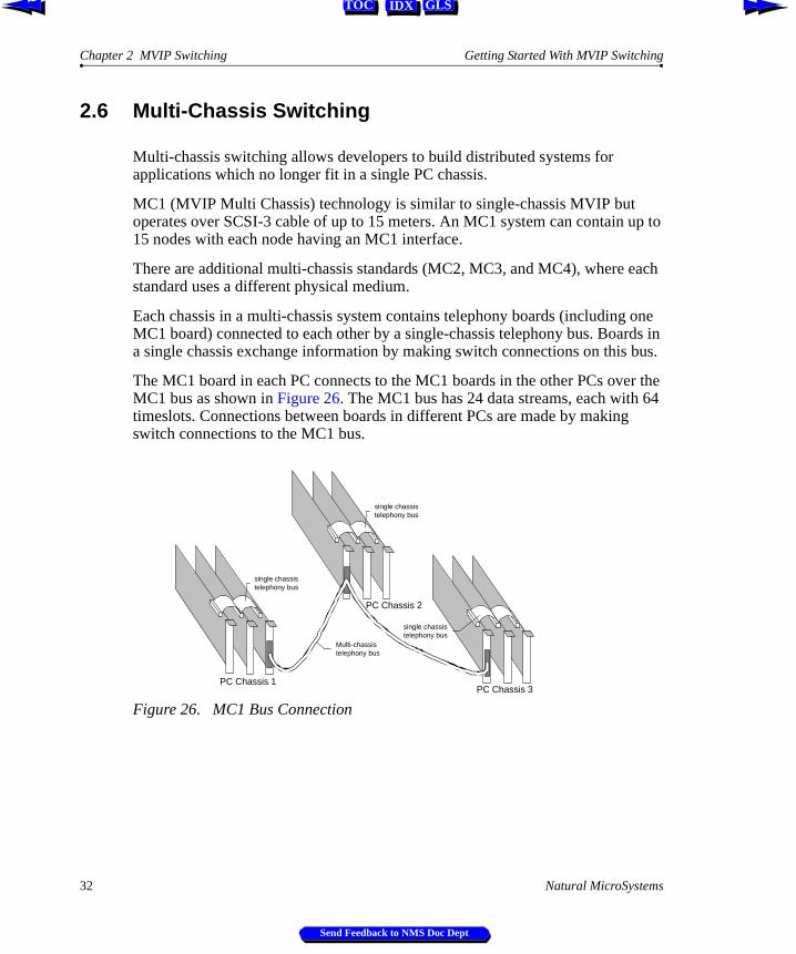
2.6 Multi-Chassis Switching
Multi-chassis switching allows developers to build distributed systems for applications which no longer fit in a single PC chassis.
MC1 (MVIP Multi Chassis) technology is similar to single-chassis MVIP but operates over SCSI-3 cable of up to 15 meters. An MC1 system can contain up to 15 nodes with each node having an MC1 interface.
There are additional multi-chassis standards (MC2, MC3, and MC4), where each standard uses a different physical medium.
Each chassis in a multi-chassis system contains telephony boards (including one MC1 board) connected to each other by a single-chassis telephony bus. Boards in a single chassis exchange information by making switch connections on this bus.
The MC1 board in each PC connects to the MC1 boards in the other PCs over the MC1 bus as shown in Figure 26. The MC1 bus has 24 data streams, each with 64 timeslots. Connections between boards in different PCs are made by making switch connections to the MC1 bus.
Figure 26. MC1 Bus Connection
PC Chassis 1
single chassistelephony bus
single chassistelephony bus
single chassistelephony bus
PC Chassis 3
PC Chassis 2
Multi-chassistelephony bus
32 Natural MicroSystems
Send Feedback to NMS Doc Dept
Getting Started With MVIP Switching Multi-Chassis Switching
IDX GLSTOC
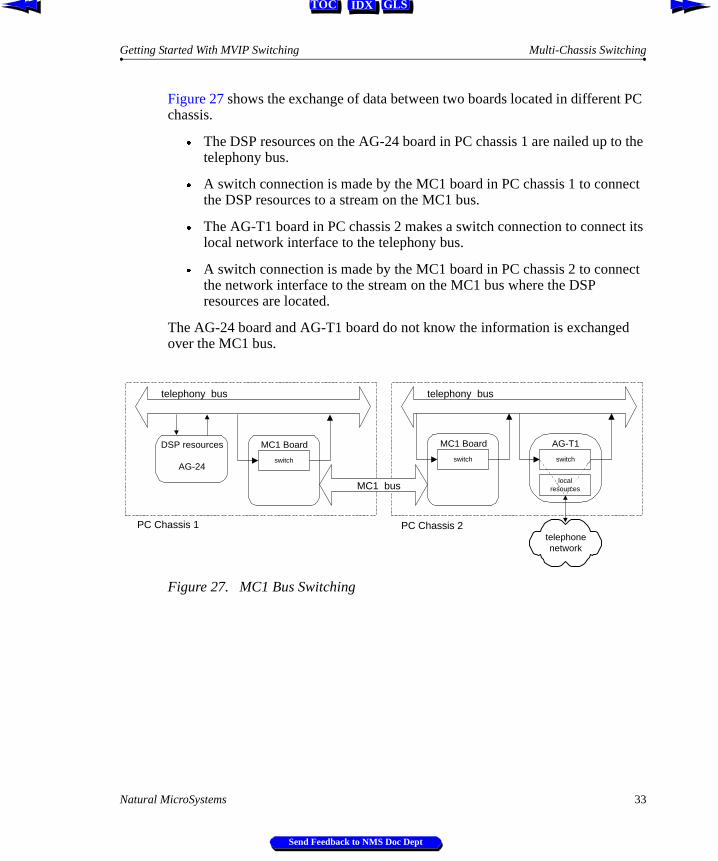
Figure 27 shows the exchange of data between two boards located in different PC chassis.
Æ The DSP resources on the AG-24 board in PC chassis 1 are nailed up to the telephony bus.
Æ A switch connection is made by the MC1 board in PC chassis 1 to connect the DSP resources to a stream on the MC1 bus.
Æ The AG-T1 board in PC chassis 2 makes a switch connection to connect its local network interface to the telephony bus.
Æ A switch connection is made by the MC1 board in PC chassis 2 to connect the network interface to the stream on the MC1 bus where the DSP resources are located.
The AG-24 board and AG-T1 board do not know the information is exchanged over the MC1 bus.
Figure 27. MC1 Bus Switching
DSP resources
AG-24
MC1 Board
telephony bus
switch
AG-T1
telephonenetwork
telephony bus
switch
localresources
MC1 Board
switch
PC Chassis 1 PC Chassis 2
MC1 bus
Natural MicroSystems 33
Send Feedback to NMS Doc Dept
Chapter 2 MVIP Switching Getting Started With MVIP Switching
IDX GLSTOC
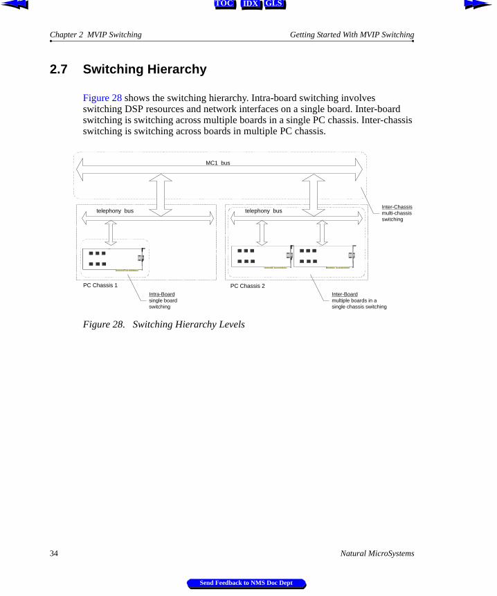
2.7 Switching Hierarchy
Figure 28 shows the switching hierarchy. Intra-board switching involves switching DSP resources and network interfaces on a single board. Inter-board switching is switching across multiple boards in a single PC chassis. Inter-chassis switching is switching across boards in multiple PC chassis.
Figure 28. Switching Hierarchy Levels
telephony bus telephony bus
PC Chassis 1 PC Chassis 2
MC1 bus
Intra-Boardsingle boardswitching
Inter-Boardmultiple boards in asingle chassis switching
Inter-Chassismulti-chassisswitching
34 Natural MicroSystems
Send Feedback to NMS Doc Dept
IDX GLSTOC
Chapter 3
The Switch Block Model
3.1 Introduction 36
3.2 MVIP-90 Switch Model 38
3.3 MVIP-90 Switching Examples 493.3.1 Local DSP Resource to Network Interface 503.3.2 Connecting Network Interface to DSP Resources (1 switch) 513.3.3 Connecting Network Interface to DSP Resources (2 switches) 523.3.4 Connecting Network Interface to Network Interface 53
3.4 MVIP-95 Switch Model 54
3.5 MVIP-95 Switching Examples 613.5.1 Local DSP Resource to Network Interface 623.5.2 Connecting Network Interface to DSP Resources (1 switch) 633.5.3 Connecting Network Interface to DSP Resources (2 switches) 643.5.4 Connecting Network Interface to Network Interface 65
Natural MicroSystems 35
Send Feedback to NMS Doc Dept
Chapter 3 The Switch Block Model Getting Started With MVIP Switching
IDX GLSTOC
ence
witch
3.1 Introduction
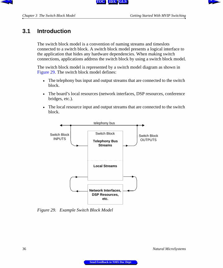
The switch block model is a convention of naming streams and timeslots connected to a switch block. A switch block model presents a logical interface to the application that hides any hardware dependencies. When making switch connections, applications address the switch block by using a switch block model.
The switch block model is represented by a switch model diagram as shown in Figure 29. The switch block model defines:
Æ The telephony bus input and output streams that are connected to the switch block.
Æ The board’s local resources (network interfaces, DSP resources, conferbridges, etc.).
Æ The local resource input and output streams that are connected to the sblock.
Figure 29. Example Switch Block Model
telephony bus
Switch BlockINPUTS
Switch BlockOUTPUTSTelephony Bus
Streams
Local Streams
Network Interfaces,DSP Resources,
etc.
Switch Block
36 Natural MicroSystems
Send Feedback to NMS Doc Dept
Getting Started With MVIP Switching Introduction
IDX GLSTOC
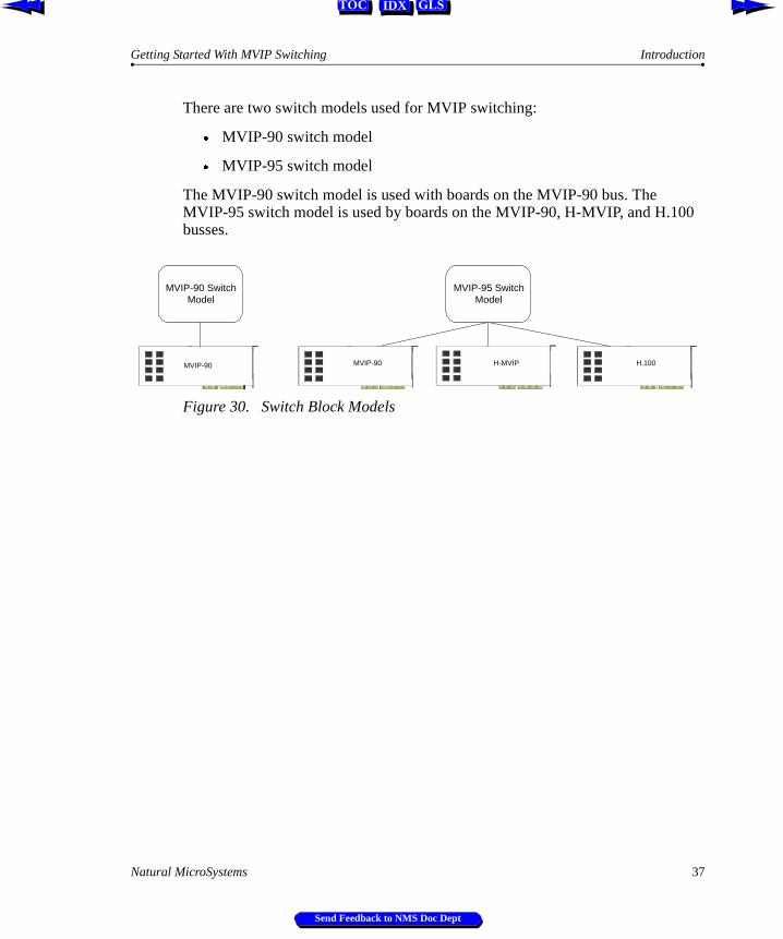
There are two switch models used for MVIP switching:
Æ MVIP-90 switch model
Æ MVIP-95 switch model
The MVIP-90 switch model is used with boards on the MVIP-90 bus. The MVIP-95 switch model is used by boards on the MVIP-90, H-MVIP, and H.100 busses.
Figure 30. Switch Block Models
MVIP-90 SwitchModel
MVIP-90
MVIP-95 SwitchModel
H.100H-MVIPMVIP-90
Natural MicroSystems 37
Send Feedback to NMS Doc Dept

Chapter 3 The Switch Block Model Getting Started With MVIP Switching
IDX GLSTOC
3.2 MVIP-90 Switch Model
The MVIP-90 bus has 16 physical wires labeled DSi0..7 and DSo0..7. In the MVIP-90 switch model, applications address the 16 MVIP bus wires as streams 0..15.
Figure 31. MVIP-90 Bus Physical Wires
Local resources on the board (i.e., network interfaces, DSP resources, etc.) are also connected to the switch block. Local resources are located on streams starting at 16.
By convention, even numbered streams are used for voice information and odd numbered streams are used for signaling information.
Stream 0 DSi 0DSo 0
Stream 1 DSi 1DSo 1
Stream 2 DSi 2DSo 2
Stream 3 DSi 3DSo 3
Stream 4 DSi 4DSo 4
Stream 5 DSi 5DSo 5
Stream 6 DSi 6DSo 6
Stream 7 DSi 7DSo 7
Physical MVIP Wire
MVIP Streams(DSP Resource toNetwork Connection)
Stream 8
Stream 9
Stream 10
Stream 11
Stream 12
Stream 13
Stream 15
Stream 14
MVIP Streams(Network to NetworkConnection)
38 Natural MicroSystems
Send Feedback to NMS Doc Dept
Getting Started With MVIP Switching MVIP-90 Switch Model
IDX GLSTOC
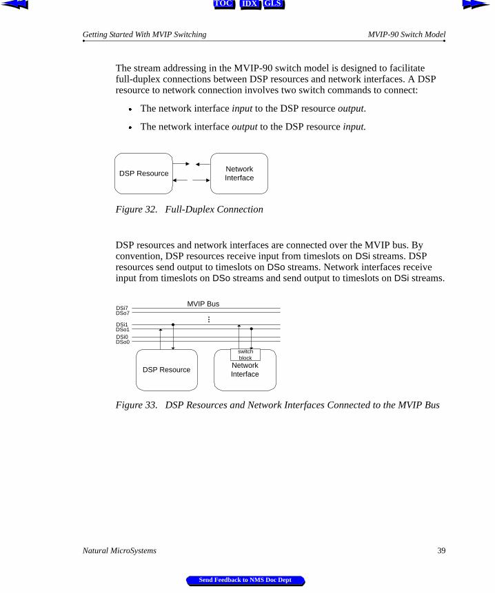
The stream addressing in the MVIP-90 switch model is designed to facilitate full-duplex connections between DSP resources and network interfaces. A DSP resource to network connection involves two switch commands to connect:
Æ The network interface input to the DSP resource output.
Æ The network interface output to the DSP resource input.
Figure 32. Full-Duplex Connection
DSP resources and network interfaces are connected over the MVIP bus. By convention, DSP resources receive input from timeslots on DSi streams. DSP resources send output to timeslots on DSo streams. Network interfaces receive input from timeslots on DSo streams and send output to timeslots on DSi streams.
Figure 33. DSP Resources and Network Interfaces Connected to the MVIP Bus
DSP ResourceNetworkInterface
DSP Resource
…
DSi0DSo0
DSo1DSi1
DSi7DSo7
NetworkInterface
MVIP Bus
switchblock
Natural MicroSystems 39
Send Feedback to NMS Doc Dept
Chapter 3 The Switch Block Model Getting Started With MVIP Switching
IDX GLSTOC
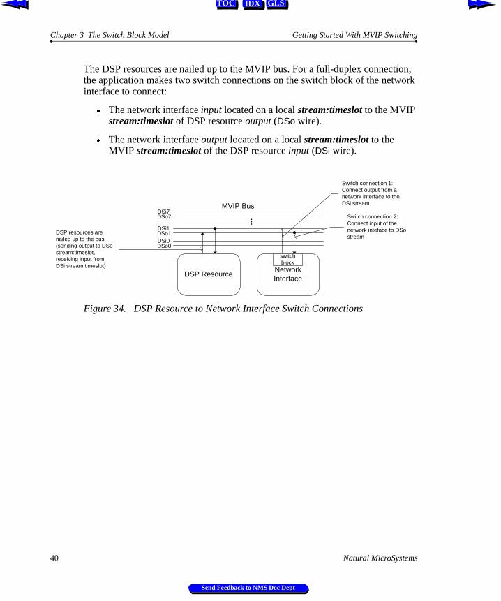
The DSP resources are nailed up to the MVIP bus. For a full-duplex connection, the application makes two switch connections on the switch block of the network interface to connect:
Æ The network interface input located on a local stream:timeslot to the MVIP stream:timeslot of DSP resource output (DSo wire).
Æ The network interface output located on a local stream:timeslot to the MVIP stream:timeslot of the DSP resource input (DSi wire).
Figure 34. DSP Resource to Network Interface Switch Connections
DSP Resource
…DSi0DSo0
DSo1DSi1
DSi7DSo7
NetworkInterface
Switch connection 2:Connect input of thenetwork inteface to DSostream
DSP resources arenailed up to the bus(sending output to DSostream:timeslot,receiving input fromDSi stream:timeslot)
Switch connection 1:Connect output from anetwork interface to theDSi streamMVIP Bus
switchblock
40 Natural MicroSystems
Send Feedback to NMS Doc Dept
Getting Started With MVIP Switching MVIP-90 Switch Model
IDX GLSTOC
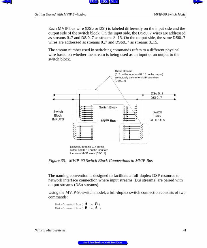
Each MVIP bus wire (DSo or DSi) is labeled differently on the input side and the output side of the switch block. On the input side, the DSo0..7 wires are addressed as streams 0..7 and DSi0..7 as streams 8..15. On the output side, the same DSi0..7 wires are addressed as streams 0..7 and DSo0..7 as streams 8..15.
The stream number used in switching commands refers to a different physical wire based on whether the stream is being used as an input or an output to the switch block.
Figure 35. MVIP-90 Switch Block Connections to MVIP Bus
The naming convention is designed to facilitate a full-duplex DSP resource to network interface connection where input streams (DSi streams) are paired with output streams (DSo streams).
Using the MVIP-90 switch model, a full-duplex switch connection consists of two commands:
MakeConnection( A to B )MakeConnection( B to A )
DSi 0..7
SwitchBlock
INPUTS
SwitchBlock
OUTPUTS
01234567 MVIP Bus
DSo 0..7
89101112131415
01234567
89
101112131415
Switch Block
These streams(0..7 on the input and 8..15 on the output)are actually the same MVIP bus wires(DSo0..7)
Likewise, streams 0..7 on theoutput and 8..15 on the input arethe same MVIP wires (DSi0..7)
Natural MicroSystems 41
Send Feedback to NMS Doc Dept
Chapter 3 The Switch Block Model Getting Started With MVIP Switching
IDX GLSTOC
For example, DSP resources are nailed up to the MVIP bus on stream 2. To connect a local resource on stream 16:1 to the MVIP bus stream 2:3, the switch command is:
MakeConnection( 16:1 to 2:3 )
This connects the voice output to the MVIP bus. To make a full-duplex connection, the MVIP bus is connected to the voice input:
MakeConnection( 2:3 to 16:1 )
In the first command, stream 2 is the input and stream 16 is the output. In the second command, stream 16 is the input and stream 2 is the output. The input and output always refer to the switch block.
MakeConnection( input to output )
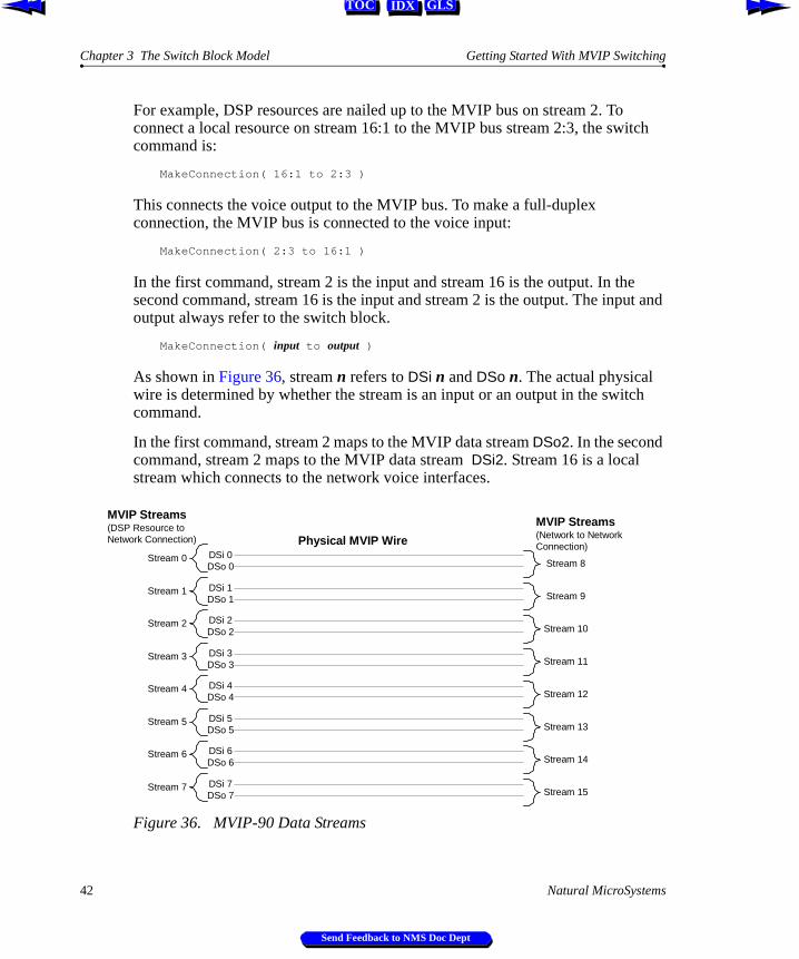
As shown in Figure 36, stream n refers to DSi n and DSo n. The actual physical wire is determined by whether the stream is an input or an output in the switch command.
In the first command, stream 2 maps to the MVIP data stream DSo2. In the second command, stream 2 maps to the MVIP data stream DSi2. Stream 16 is a local stream which connects to the network voice interfaces.
Figure 36. MVIP-90 Data Streams
Stream 0 DSi 0DSo 0
Stream 1 DSi 1DSo 1
Stream 2 DSi 2DSo 2
Stream 3 DSi 3DSo 3
Stream 4 DSi 4DSo 4
Stream 5 DSi 5DSo 5
Stream 6 DSi 6DSo 6
Stream 7 DSi 7DSo 7
Physical MVIP Wire
MVIP Streams(DSP Resource toNetwork Connection)
Stream 8
Stream 9
Stream 10
Stream 11
Stream 12
Stream 13
Stream 15
Stream 14
MVIP Streams(Network to NetworkConnection)
42 Natural MicroSystems
Send Feedback to NMS Doc Dept
Getting Started With MVIP Switching MVIP-90 Switch Model
IDX GLSTOC
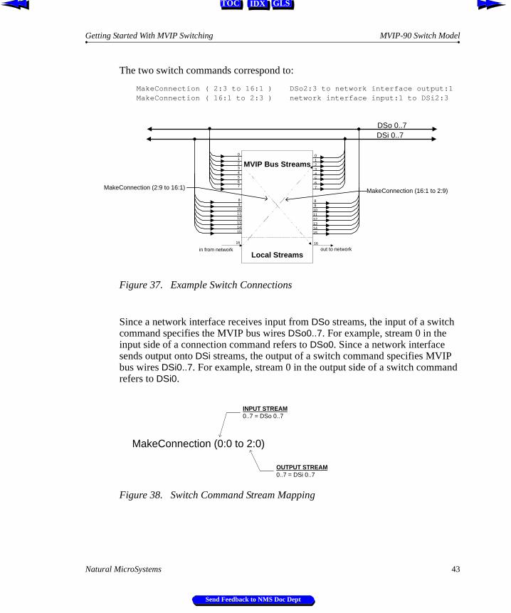
The two switch commands correspond to:
MakeConnection ( 2:3 to 16:1 ) DSo2:3 to network interface output:1MakeConnection ( 16:1 to 2:3 ) network interface input:1 to DSi2:3
Figure 37. Example Switch Connections
Since a network interface receives input from DSo streams, the input of a switch command specifies the MVIP bus wires DSo0..7. For example, stream 0 in the input side of a connection command refers to DSo0. Since a network interface sends output onto DSi streams, the output of a switch command specifies MVIP bus wires DSi0..7. For example, stream 0 in the output side of a switch command refers to DSi0.
Figure 38. Switch Command Stream Mapping
DSi 0..7DSo 0..7
89
101112131415
01234567
89101112131415
Switch Block01234567
MVIP Bus Streams
Local Streams
MakeConnection (2:9 to 16:1)
16 16
in from network out to network
MakeConnection (16:1 to 2:9)
MakeConnection (0:0 to 2:0)
INPUT STREAM0..7 = DSo 0..7
OUTPUT STREAM0..7 = DSi 0..7
Natural MicroSystems 43
Send Feedback to NMS Doc Dept
Chapter 3 The Switch Block Model Getting Started With MVIP Switching
IDX GLSTOC
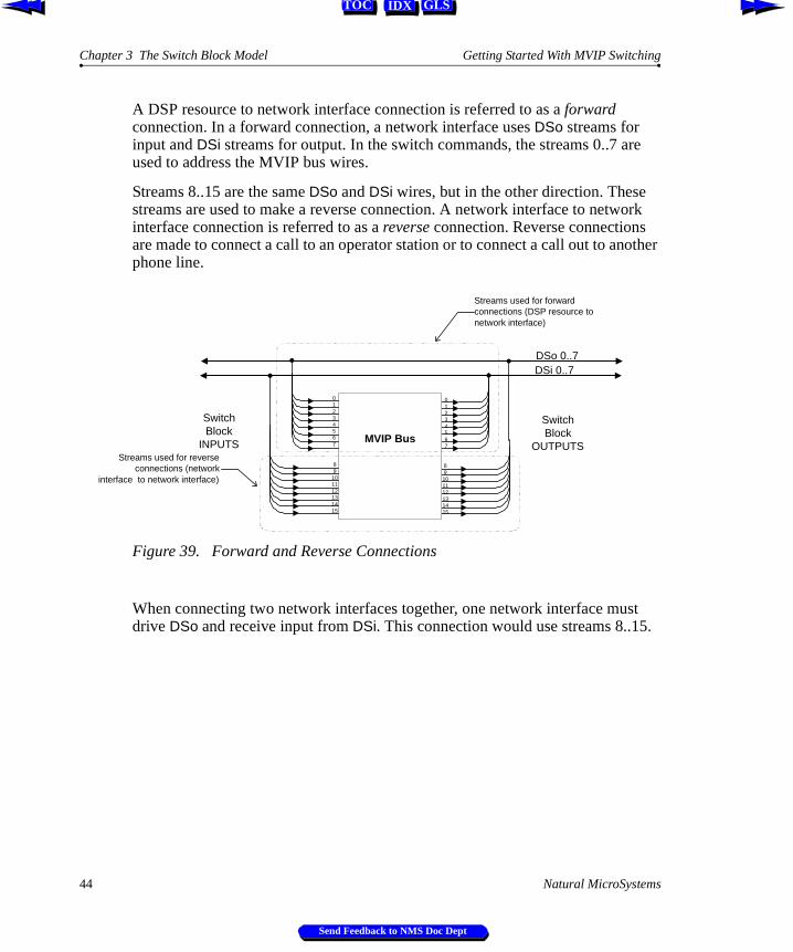
A DSP resource to network interface connection is referred to as a forward connection. In a forward connection, a network interface uses DSo streams for input and DSi streams for output. In the switch commands, the streams 0..7 are used to address the MVIP bus wires.
Streams 8..15 are the same DSo and DSi wires, but in the other direction. These streams are used to make a reverse connection. A network interface to network interface connection is referred to as a reverse connection. Reverse connections are made to connect a call to an operator station or to connect a call out to another phone line.
Figure 39. Forward and Reverse Connections
When connecting two network interfaces together, one network interface must drive DSo and receive input from DSi. This connection would use streams 8..15.
DSi 0..7
SwitchBlock
INPUTS
SwitchBlock
OUTPUTS
DSo 0..7
89
101112131415
01234567
89101112131415
Switch Block01234567
MVIP Bus
Streams used for forwardconnections (DSP resource tonetwork interface)
Streams used for reverseconnections (network
interface to network interface)
44 Natural MicroSystems
Send Feedback to NMS Doc Dept
Getting Started With MVIP Switching MVIP-90 Switch Model
IDX GLSTOC
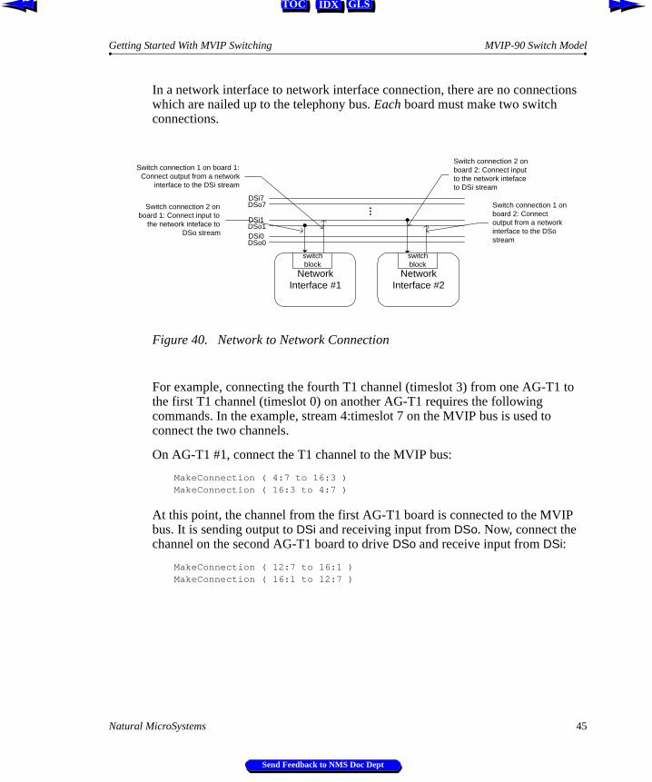
In a network interface to network interface connection, there are no connections which are nailed up to the telephony bus. Each board must make two switch connections.
Figure 40. Network to Network Connection
For example, connecting the fourth T1 channel (timeslot 3) from one AG-T1 to the first T1 channel (timeslot 0) on another AG-T1 requires the following commands. In the example, stream 4:timeslot 7 on the MVIP bus is used to connect the two channels.
On AG-T1 #1, connect the T1 channel to the MVIP bus:
MakeConnection ( 4:7 to 16:3 )MakeConnection ( 16:3 to 4:7 )
At this point, the channel from the first AG-T1 board is connected to the MVIP bus. It is sending output to DSi and receiving input from DSo. Now, connect the channel on the second AG-T1 board to drive DSo and receive input from DSi:
MakeConnection ( 12:7 to 16:1 )MakeConnection ( 16:1 to 12:7 )
NetworkInterface #1
…
DSi0DSo0
DSo1DSi1
DSi7DSo7
NetworkInterface #2
Switch connection 2 onboard 1: Connect input to
the network inteface toDSo stream
Switch connection 1 on board 1:Connect output from a network
interface to the DSi stream
Switch connection 1 onboard 2: Connectoutput from a networkinterface to the DSostream
Switch connection 2 onboard 2: Connect inputto the network intefaceto DSi stream
switchblock
switchblock
Natural MicroSystems 45
Send Feedback to NMS Doc Dept
Chapter 3 The Switch Block Model Getting Started With MVIP Switching
IDX GLSTOC
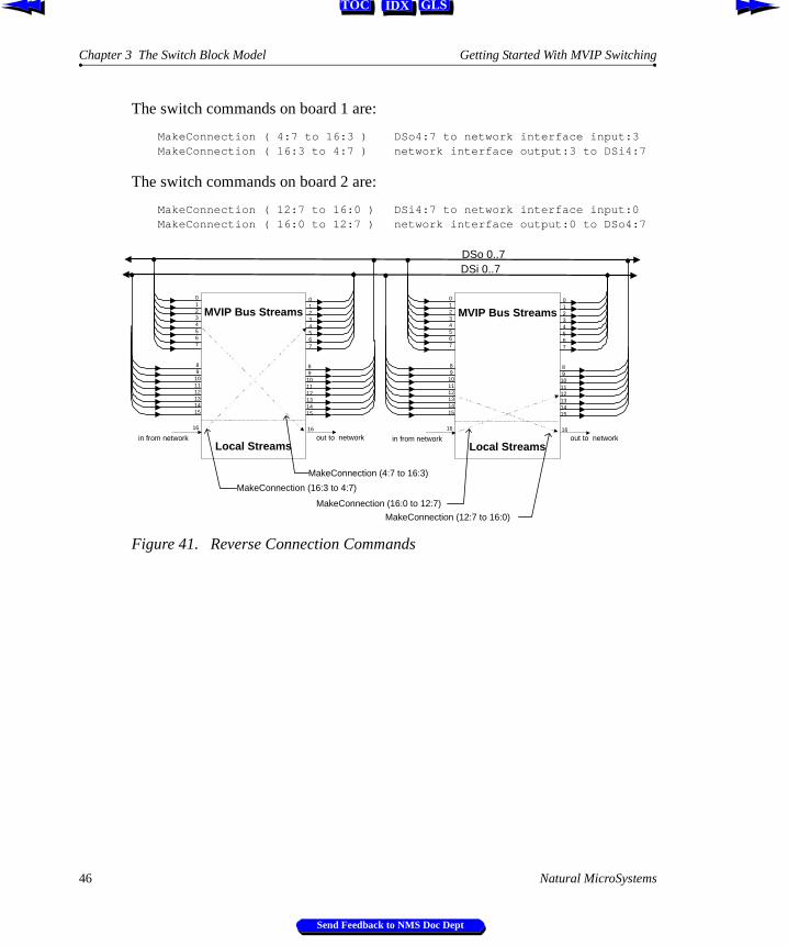
The switch commands on board 1 are:
MakeConnection ( 4:7 to 16:3 ) DSo4:7 to network interface input:3MakeConnection ( 16:3 to 4:7 ) network interface output:3 to DSi4:7
The switch commands on board 2 are:
MakeConnection ( 12:7 to 16:0 ) DSi4:7 to network interface input:0MakeConnection ( 16:0 to 12:7 ) network interface output:0 to DSo4:7
Figure 41. Reverse Connection Commands
DSi 0..7DSo 0..7
89
101112131415
01234567
89
101112131415
Switch Block01234567
MVIP Bus Streams
Local Streams
MakeConnection (16:3 to 4:7)
16 16
in from network out to network
MakeConnection (4:7 to 16:3)
89
101112131415
01234567
89
101112131415
Switch Block01234567
MVIP Bus Streams
Local Streams
16 16
in from network out to network
MakeConnection (12:7 to 16:0)
MakeConnection (16:0 to 12:7)
46 Natural MicroSystems
Send Feedback to NMS Doc Dept
Getting Started With MVIP Switching MVIP-90 Switch Model
IDX GLSTOC
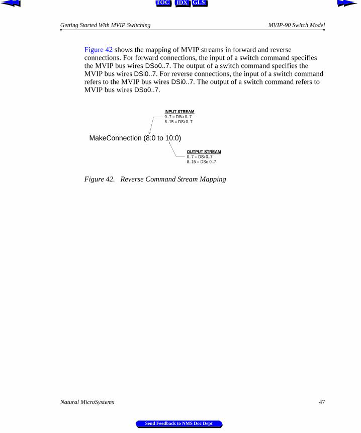
Figure 42 shows the mapping of MVIP streams in forward and reverse connections. For forward connections, the input of a switch command specifies the MVIP bus wires DSo0..7. The output of a switch command specifies the MVIP bus wires DSi0..7. For reverse connections, the input of a switch command refers to the MVIP bus wires DSi0..7. The output of a switch command refers to MVIP bus wires DSo0..7.
Figure 42. Reverse Command Stream Mapping
MakeConnection (8:0 to 10:0)
INPUT STREAM0..7 = DSo 0..78..15 = DSi 0..7
OUTPUT STREAM0..7 = DSi 0..78..15 = DSo 0..7
Natural MicroSystems 47
Send Feedback to NMS Doc Dept
Chapter 3 The Switch Block Model Getting Started With MVIP Switching
IDX GLSTOC
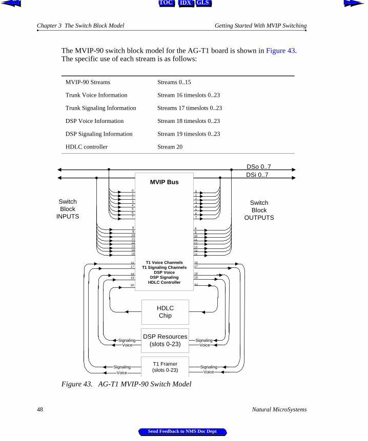
The MVIP-90 switch block model for the AG-T1 board is shown in Figure 43. The specific use of each stream is as follows:
Figure 43. AG-T1 MVIP-90 Switch Model
MVIP-90 Streams Streams 0..15
Trunk Voice Information Stream 16 timeslots 0..23
Trunk Signaling Information Streams 17 timeslots 0..23
DSP Voice Information Stream 18 timeslots 0..23
DSP Signaling Information Stream 19 timeslots 0..23
HDLC controller Stream 20
Voice
Signaling
Signaling
DSi 0..7
SwitchBlock
INPUTS
SwitchBlock
OUTPUTS
SignalingVoice
Signaling
01234567
Voice
Voice
T1 Framer(slots 0-23)
DSP Resources(slots 0-23)
HDLCChip
1617
1819
20
DSo 0..7
89
101112131415
01234567
89101112131415
1617
1819
20
MVIP Bus
T1 Voice ChannelsT1 Signaling Channels
DSP VoiceDSP Signaling
HDLC Controller
48 Natural MicroSystems
Send Feedback to NMS Doc Dept
Getting Started With MVIP Switching MVIP-90 Switching Examples
IDX GLSTOC
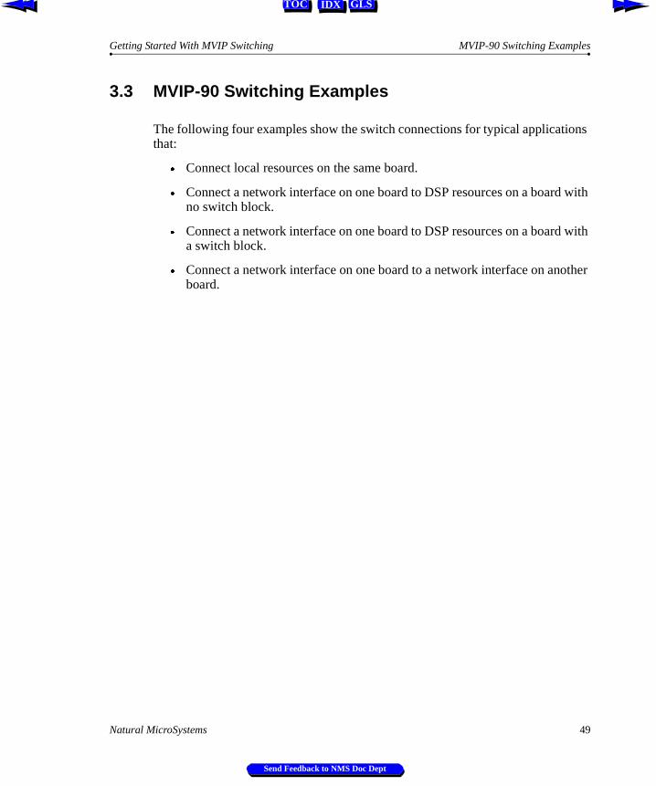
3.3 MVIP-90 Switching Examples
The following four examples show the switch connections for typical applications that:
Æ Connect local resources on the same board.
Æ Connect a network interface on one board to DSP resources on a board with no switch block.
Æ Connect a network interface on one board to DSP resources on a board with a switch block.
Æ Connect a network interface on one board to a network interface on another board.
Natural MicroSystems 49
Send Feedback to NMS Doc Dept
Chapter 3 The Switch Block Model Getting Started With MVIP Switching
IDX GLSTOC
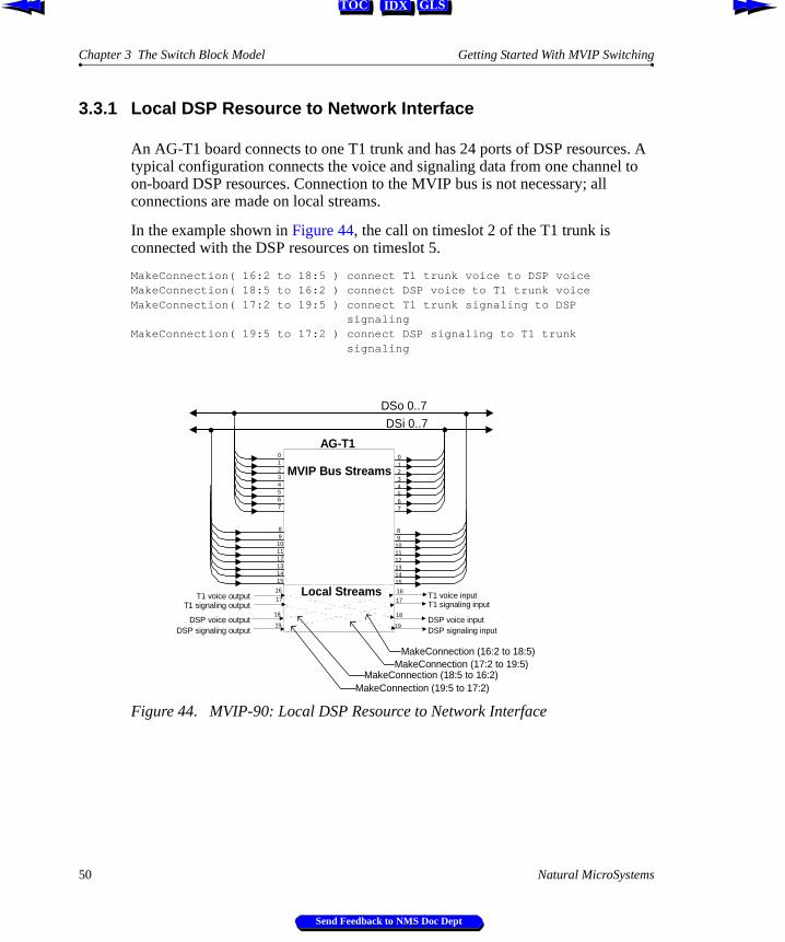
3.3.1 Local DSP Resource to Network Interface
An AG-T1 board connects to one T1 trunk and has 24 ports of DSP resources. A typical configuration connects the voice and signaling data from one channel to on-board DSP resources. Connection to the MVIP bus is not necessary; all connections are made on local streams.
In the example shown in Figure 44, the call on timeslot 2 of the T1 trunk is connected with the DSP resources on timeslot 5.
MakeConnection( 16:2 to 18:5 ) connect T1 trunk voice to DSP voiceMakeConnection( 18:5 to 16:2 ) connect DSP voice to T1 trunk voiceMakeConnection( 17:2 to 19:5 ) connect T1 trunk signaling to DSP signalingMakeConnection( 19:5 to 17:2 ) connect DSP signaling to T1 trunk signaling
Figure 44. MVIP-90: Local DSP Resource to Network Interface
89101112131415
01234567
89
101112131415
Switch Block01234567
MVIP Bus Streams
MakeConnection (16:2 to 18:5)
16 16T1 voice output T1 voice input
MakeConnection (19:5 to 17:2)
18DSP voice input
18DSP voice output
Local Streams17
T1 signaling output17
T1 signaling input
19DSP signaling output
19DSP signaling input
MakeConnection (18:5 to 16:2)MakeConnection (17:2 to 19:5)
AG-T1
DSi 0..7
DSo 0..7
50 Natural MicroSystems
Send Feedback to NMS Doc Dept
Getting Started With MVIP Switching Connecting Network Interface to DSP Resources (1 switch)
IDX GLSTOC
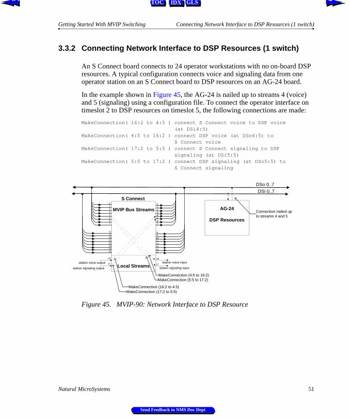
3.3.2 Connecting Network Interface to DSP Resources (1 switch)
An S Connect board connects to 24 operator workstations with no on-board DSP resources. A typical configuration connects voice and signaling data from one operator station on an S Connect board to DSP resources on an AG-24 board.
In the example shown in Figure 45, the AG-24 is nailed up to streams 4 (voice) and 5 (signaling) using a configuration file. To connect the operator interface on timeslot 2 to DSP resources on timeslot 5, the following connections are made:
MakeConnection( 16:2 to 4:5 ) connect S Connect voice to DSP voice (at DSi4:5)MakeConnection( 4:5 to 16:2 ) connect DSP voice (at DSo4:5) to S Connect voiceMakeConnection( 17:2 to 5:5 ) connect S Connect signaling to DSP signaling (at DSi5:5)MakeConnection( 5:5 to 17:2 ) connect DSP signaling (at DSo5:5) to S Connect signaling
Figure 45. MVIP-90: Network Interface to DSP Resource
DSi 0..7DSo 0..7
89
101112131415
01234567
89
101112131415
Switch Block01234567
MVIP Bus Streams
Local Streams
MakeConnection (17:2 to 5:5)
16 16
station voice output station voice input
MakeConnection (16:2 to 4:5)
Switch BlockAG-24
DSP Resources
Connection nailed upto streams 4 and 5
17
station signaling output17
station signaling input
MakeConnection (5:5 to 17:2)MakeConnection (4:5 to 16:2)
S Connect
Natural MicroSystems 51
Send Feedback to NMS Doc Dept
Chapter 3 The Switch Block Model Getting Started With MVIP Switching
IDX GLSTOC
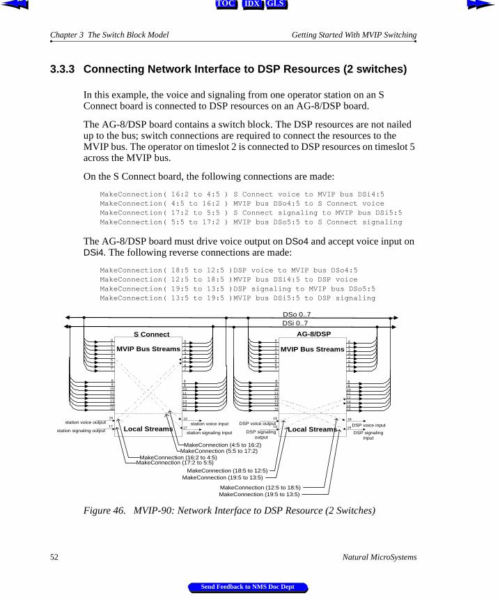
3.3.3 Connecting Network Interface to DSP Resources (2 switches)
In this example, the voice and signaling from one operator station on an S Connect board is connected to DSP resources on an AG-8/DSP board.
The AG-8/DSP board contains a switch block. The DSP resources are not nailed up to the bus; switch connections are required to connect the resources to the MVIP bus. The operator on timeslot 2 is connected to DSP resources on timeslot 5 across the MVIP bus.
On the S Connect board, the following connections are made:
MakeConnection( 16:2 to 4:5 ) S Connect voice to MVIP bus DSi4:5MakeConnection( 4:5 to 16:2 ) MVIP bus DSo4:5 to S Connect voiceMakeConnection( 17:2 to 5:5 ) S Connect signaling to MVIP bus DSi5:5MakeConnection( 5:5 to 17:2 ) MVIP bus DSo5:5 to S Connect signaling
The AG-8/DSP board must drive voice output on DSo4 and accept voice input on DSi4. The following reverse connections are made:
MakeConnection( 18:5 to 12:5 )DSP voice to MVIP bus DSo4:5MakeConnection( 12:5 to 18:5 )MVIP bus DSi4:5 to DSP voiceMakeConnection( 19:5 to 13:5 )DSP signaling to MVIP bus DSo5:5MakeConnection( 13:5 to 19:5 )MVIP bus DSi5:5 to DSP signaling
Figure 46. MVIP-90: Network Interface to DSP Resource (2 Switches)
DSi 0..7DSo 0..7
89
101112131415
01234567
89
101112131415
Switch Block01234567
MVIP Bus Streams
Local Streams
MakeConnection (16:2 to 4:5)
16 16station voice output station voice input
MakeConnection (4:5 to 16:2)
89
101112131415
01234567
89
101112131415
Switch Block01234567
MVIP Bus Streams
Local Streams
18 18DSP voice output DSP voice input
MakeConnection (12:5 to 18:5)
MakeConnection (18:5 to 12:5)
S Connect AG-8/DSP
17station signaling output
17
station signaling input19
DSP signalingoutput
19
DSP signalinginput
MakeConnection (17:2 to 5:5)
MakeConnection (5:5 to 17:2)
MakeConnection (19:5 to 13:5)
MakeConnection (19:5 to 13:5)
52 Natural MicroSystems
Send Feedback to NMS Doc Dept
Getting Started With MVIP Switching Connecting Network Interface to Network Interface
IDX GLSTOC
3.3.4 Connecting Network Interface to Network Interface
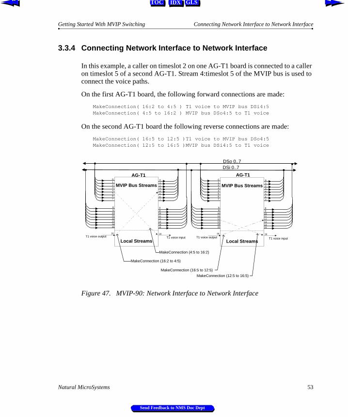
In this example, a caller on timeslot 2 on one AG-T1 board is connected to a caller on timeslot 5 of a second AG-T1. Stream 4:timeslot 5 of the MVIP bus is used to connect the voice paths.
On the first AG-T1 board, the following forward connections are made:
MakeConnection( 16:2 to 4:5 ) T1 voice to MVIP bus DSi4:5MakeConnection( 4:5 to 16:2 ) MVIP bus DSo4:5 to T1 voice
On the second AG-T1 board the following reverse connections are made:
MakeConnection( 16:5 to 12:5 )T1 voice to MVIP bus DSo4:5MakeConnection( 12:5 to 16:5 )MVIP bus DSi4:5 to T1 voice
Figure 47. MVIP-90: Network Interface to Network Interface
DSi 0..7DSo 0..7
89101112131415
01234567
89
101112131415
Switch Block01234567
MVIP Bus Streams
Local Streams
MakeConnection (16:2 to 4:5)
16 16T1 voice output T1 voice input
MakeConnection (4:5 to 16:2)
89
101112131415
01234567
89
101112131415
Switch Block01234567
MVIP Bus Streams
Local Streams
16 16T1 voice output T1 voice input
MakeConnection (12:5 to 16:5)
MakeConnection (16:5 to 12:5)
AG-T1 AG-T1
Natural MicroSystems 53
Send Feedback to NMS Doc Dept
Chapter 3 The Switch Block Model Getting Started With MVIP Switching
IDX GLSTOC
0.
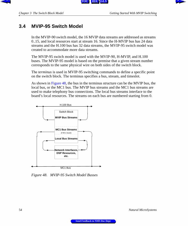
3.4 MVIP-95 Switch Model
In the MVIP-90 switch model, the 16 MVIP data streams are addressed as streams 0..15, and local resources start at stream 16. Since the H-MVIP bus has 24 data streams and the H.100 bus has 32 data streams, the MVIP-95 switch model was created to accommodate more data streams.
The MVIP-95 switch model is used with the MVIP-90, H-MVIP, and H.100 buses. The MVIP-95 model is based on the premise that a given stream number corresponds to the same physical wire on both sides of the switch block.
The terminus is used in MVIP-95 switching commands to define a specific point on the switch block. The terminus specifies a bus, stream, and timeslot.
As shown in Figure 48, the bus in the terminus structure can be the MVIP bus, the local bus, or the MC1 bus. The MVIP bus streams and the MC1 bus streams are used to make telephony bus connections. The local bus streams interface to the board’s local resources. The streams on each bus are numbered starting from
Figure 48. MVIP-95 Switch Model Busses
H.100 Bus
MVIP Bus Streams
MC1 Bus Streams(if MC1 board)
Local Bus Streams
Network Interfaces,DSP Resources,
etc.
Switch Block
MC1 Bus
54 Natural MicroSystems
Send Feedback to NMS Doc Dept
Getting Started With MVIP Switching MVIP-95 Switch Model
IDX GLSTOC
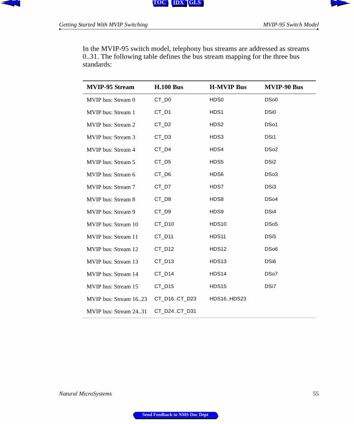
In the MVIP-95 switch model, telephony bus streams are addressed as streams 0..31. The following table defines the bus stream mapping for the three bus standards:
MVIP-95 Stream H.100 Bus H-MVIP Bus MVIP-90 Bus
MVIP bus: Stream 0 CT_D0 HDS0 DSo0
MVIP bus: Stream 1 CT_D1 HDS1 DSi0
MVIP bus: Stream 2 CT_D2 HDS2 DSo1
MVIP bus: Stream 3 CT_D3 HDS3 DSi1
MVIP bus: Stream 4 CT_D4 HDS4 DSo2
MVIP bus: Stream 5 CT_D5 HDS5 DSi2
MVIP bus: Stream 6 CT_D6 HDS6 DSo3
MVIP bus: Stream 7 CT_D7 HDS7 DSi3
MVIP bus: Stream 8 CT_D8 HDS8 DSo4
MVIP bus: Stream 9 CT_D9 HDS9 DSi4
MVIP bus: Stream 10 CT_D10 HDS10 DSo5
MVIP bus: Stream 11 CT_D11 HDS11 DSi5
MVIP bus: Stream 12 CT_D12 HDS12 DSo6
MVIP bus: Stream 13 CT_D13 HDS13 DSi6
MVIP bus: Stream 14 CT_D14 HDS14 DSo7
MVIP bus: Stream 15 CT_D15 HDS15 DSi7
MVIP bus: Stream 16..23 CT_D16..CT_D23 HDS16..HDS23
MVIP bus: Stream 24..31 CT_D24..CT_D31
Natural MicroSystems 55
Send Feedback to NMS Doc Dept
Chapter 3 The Switch Block Model Getting Started With MVIP Switching
IDX GLSTOC
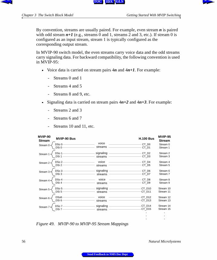
By convention, streams are usually paired. For example, even stream n is paired with odd stream n+1 (e.g., streams 0 and 1, streams 2 and 3, etc.). If stream 0 is configured as an input stream, stream 1 is typically configured as the corresponding output stream.
In MVIP-90 switch model, the even streams carry voice data and the odd streams carry signaling data. For backward compatibility, the following convention is used in MVIP-95:
Æ Voice data is carried on stream pairs 4n and 4n+1. For example:
- Streams 0 and 1
- Streams 4 and 5
- Streams 8 and 9, etc.
Æ Signaling data is carried on stream pairs 4n+2 and 4n+3. For example:
- Streams 2 and 3
- Streams 6 and 7
- Streams 10 and 11, etc.
Figure 49. MVIP-90 to MVIP-95 Stream Mappings
Stream 0 DSo 0DSi 0
Stream 1 DSo 1DSi 1
Stream 2 DSo 2DSi 2
Stream 3 DSo 3DSi 3
Stream 4 DSo 4DSi 4
Stream 5 DSo 5DSi 5
Stream 6 DSo6DSi 6
Stream 7 DSo 7DSi 7
CT_D0CT_D1
CT_D2CT_D3
CT_D4CT_D5
CT_D6CT_D7
CT_D8CT_D9
CT_D10CT_D11
CT_D12CT_D13
CT_D14CT_D15
.
.
.
Stream 0Stream 1
Stream 2Stream 3
Stream 4Stream 5
Stream 6Stream 7
Stream 8Stream 9
Stream 10Stream 11
Stream 12Stream 13
Stream 14Stream 15
.
.
.
MVIP-90Stream
voicestreams
voicestreams
signalingstreams
signalingstreams
signalingstreams
signalingstreams
voicestreams
voicestreams
MVIP-90 Bus H.100 Bus MVIP-95Stream
56 Natural MicroSystems
Send Feedback to NMS Doc Dept
Getting Started With MVIP Switching MVIP-95 Switch Model
IDX GLSTOC
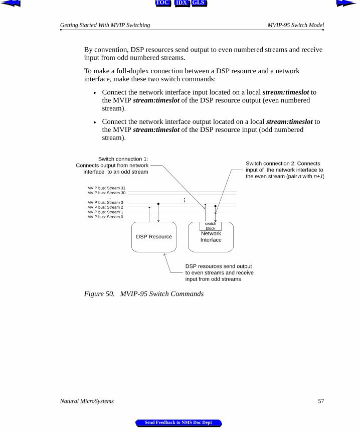
By convention, DSP resources send output to even numbered streams and receive input from odd numbered streams.
To make a full-duplex connection between a DSP resource and a network interface, make these two switch commands:
Æ Connect the network interface input located on a local stream:timeslot to the MVIP stream:timeslot of the DSP resource output (even numbered stream).
Æ Connect the network interface output located on a local stream:timeslot to the MVIP stream:timeslot of the DSP resource input (odd numbered stream).
Figure 50. MVIP-95 Switch Commands
DSP Resource
…
NetworkInterface
Switch connection 2: Connectsinput of the network interface tothe even stream (pair n with n+1)
Switch connection 1:Connects output from network
interface to an odd stream
DSP resources send outputto even streams and receiveinput from odd streams
MVIP bus: Stream 31MVIP bus: Stream 30 …MVIP bus: Stream 3MVIP bus: Stream 2MVIP bus: Stream 1MVIP bus: Stream 0
switchblock
Natural MicroSystems 57
Send Feedback to NMS Doc Dept
Chapter 3 The Switch Block Model Getting Started With MVIP Switching
IDX GLSTOC
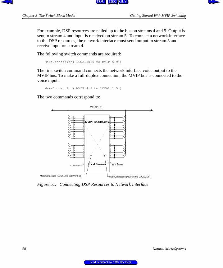
For example, DSP resources are nailed up to the bus on streams 4 and 5. Output is sent to stream 4 and input is received on stream 5. To connect a network interface to the DSP resources, the network interface must send output to stream 5 and receive input on stream 4.
The following switch commands are required:
MakeConnection( LOCAL:0:5 to MVIP:5:9 )
The first switch command connects the network interface voice output to the MVIP bus. To make a full-duplex connection, the MVIP bus is connected to the voice input:
MakeConnection( MVIP:4:9 to LOCAL:1:5 )
The two commands correspond to:
Figure 51. Connecting DSP Resources to Network Interface
CT_D0..31
0123456789
101112...
2425262728293031
0123456789101112...
2425262728293031
MVIP Bus Streams
Local Streams1
0in from network out to network
MakeConnection (LOCAL:0:5 to MVIP:5:9) MakeConnection (MVIP:4:9 to LOCAL:1:5)
58 Natural MicroSystems
Send Feedback to NMS Doc Dept
Getting Started With MVIP Switching MVIP-95 Switch Model
IDX GLSTOC
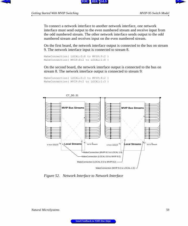
To connect a network interface to another network interface, one network interface must send output to the even numbered stream and receive input from the odd numbered stream. The other network interface sends output to the odd numbered stream and receives input on the even numbered stream.
On the first board, the network interface output is connected to the bus on stream 9. The network interface input is connected to stream 8.
MakeConnection( LOCAL:0:8 to MVIP:9:2 )MakeConnection( MVIP:8:2 to LOCAL:1:8 )
On the second board, the network interface output is connected to the bus on stream 8. The network interface output is connected to stream 9:
MakeConnection( LOCAL:0:3 to MVIP:8:2 )MakeConnection( MVIP:9:2 to LOCAL:1:3 )
Figure 52. Network Interface to Network Interface
CT_D0..31
0123456789101112...
2425262728293031
0123456789
101112...
2425262728293031
MVIP Bus Streams
Local Streams1
0in from network out to network
MakeConnection (LOCAL:0:8 to MVIP:9:2)
MakeConnection (MVIP:8:2 to LOCAL:1:8)
0123456789101112...
2425262728293031
0123456789101112...
2425262728293031
MVIP Bus Streams
Local Streams1
0in from network out to network
MakeConnection (LOCAL:0:3 to MVIP:8:2)
MakeConnection (MVIP:9:2 to LOCAL:1:3)
Natural MicroSystems 59
Send Feedback to NMS Doc Dept
Chapter 3 The Switch Block Model Getting Started With MVIP Switching
IDX GLSTOC
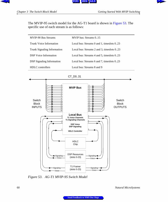
The MVIP-95 switch model for the AG-T1 board is shown in Figure 53. The specific use of each stream is as follows:
Figure 53. AG-T1 MVIP-95 Switch Model
MVIP-90 Bus Streams MVIP bus: Streams 0..15
Trunk Voice Information Local bus: Streams 0 and 1, timeslots 0..23
Trunk Signaling Information Local bus: Streams 2 and 3, timeslots 0..23
DSP Voice Information Local bus: Streams 4 and 5, timeslots 0..23
DSP Signaling Information Local bus: Streams 6 and 7, timeslots 0..23
HDLC controllers Local bus: Streams 8 and 9
Voice
Signaling
Signaling
CT_D0..31
SwitchBlock
INPUTS
SwitchBlock
OUTPUTS
Signaling
Voice
Signaling
0123456789
101112131415
Voice
Voice
T1 Framer(slots 0-23)
DSP Resources(slots 0-23)
HDLCChip
02
46
8
13
57
9
MVIP Bus
Local BusT1 Voice Channels
T1 Signaling Channels
DSP VoiceDSP Signaling
HDLC Controller
0123456789
101112131415
60 Natural MicroSystems
Send Feedback to NMS Doc Dept
Getting Started With MVIP Switching MVIP-95 Switching Examples
IDX GLSTOC
3.5 MVIP-95 Switching Examples
The following four examples show MVIP-95 switch connections for typical applications that:
Æ Connect local resources on the same board.
Æ Connect a network interface on one board to DSP resources on a board with no switch.
Æ Connect a network interface on one board to DSP resources on a board with a switch.
Æ Connecting a network interface on one board to a network interface on another board.
Natural MicroSystems 61
Send Feedback to NMS Doc Dept
Chapter 3 The Switch Block Model Getting Started With MVIP Switching
IDX GLSTOC
3.5.1 Local DSP Resource to Network Interface
An AG-T1 board connects to one T1 trunk and has 24 ports of DSP resources. A typical configuration connects the voice data and signaling data from one channel to on-board DSP resources. Connection to the MVIP bus is not necessary; all connections are made on local streams.
In the example shown in Figure 54, the call on timeslot 2 of the T1 trunk is connected with the DSP resources on timeslot 5.
MakeConnection( LOCAL:0:2 to LOCAL:5:5 ) T1 trunk voice to DSP voiceMakeConnection( LOCAL:4:5 to LOCAL:1:2 ) DSP voice to T1 trunk voiceMakeConnection( LOCAL:2:2 to LOCAL:7:5 ) T1 trunk signaling to DSP signalingMakeConnection( LOCAL:6:5 to LOCAL:3:2 DSP signaling to T1 trunk signaling
Figure 54. MVIP-95: Local DSP Resource to Network Interface
T1 signaling output
0123456789
101112...
2425262728293031
0123456789
101112...
2425262728293031
MVIP Bus Streams
10T1 voice output T1 voice input
MakeConnection (LOCAL:4:5 to LOCAL:1:2)MakeConnection (LOCAL:0:2 to LOCAL:5:5)
4DSP voice output
5
DSP voice input
AG-T1
2 3
T1 signaling input
6DSP signaling output
7
DSP signaling input
Local Streams
MakeConnection (LOCAL:6:5 to LOCAL:3:2)MakeConnection (LOCAL:2:2 to LOCAL:7:5)
62 Natural MicroSystems
Send Feedback to NMS Doc Dept
Getting Started With MVIP Switching Connecting Network Interface to DSP Resources (1 switch)
IDX GLSTOC
3.5.2 Connecting Network Interface to DSP Resources (1 switch)
An S Connect board connects to 24 operator workstations with no DSP resources. A typical configuration is connecting voice and signaling from one operator station on an S Connect board to DSP resources on an AG-24 board using MVIP bus streams 8 and 9 (voice) and 10 and 11 (signaling).
In the example shown in Figure 55, the AG-24 is nailed up to streams 8 and 9 (voice) and 10 and 11(signaling). The operator on timeslot 2 is connected to DSP resources on timeslot 5 across the MVIP bus.
MakeConnection( LOCAL:0:2 to MVIP:9:5 ) S Connect voice to DSP voice (at CT_D9:5)MakeConnection( MVIP:8:5 to LOCAL:1:2 ) DSP voice (at CT_D8:5) to S Connect voiceMakeConnection( LOCAL:2:2 to MVIP:11:5 ) S Connect signaling to DSP signaling (at CT_D11:5)MakeConnection( MVIP:10:5 to LOCAL:3:2 ) DSP signaling (at CT_D10:5) to S Connect signaling
Figure 55. MVIP-95: Network Interface to DSP Resource
0123456789
101112...
2425262728293031
0123456789
101112...
2425262728293031
MVIP Bus Streams
10station voice output station voice input
MakeConnection (LOCAL:0:2 to MVIP:9:5)
MakeConnection (MVIP:8:5 to LOCAL:1:2)
AG-24
DSP Resources
Connection nailed upto streams 8 and 9
(voice), 10 and 11(signaling)
2
station signaling output3
station signaling input
MakeConnection (LOCAL:2:2 to MVIP:11:5)
MakeConnection (MVIP10:5 to LOCAL:3:2)
S Connect
Local Streams
Natural MicroSystems 63
Send Feedback to NMS Doc Dept
Chapter 3 The Switch Block Model Getting Started With MVIP Switching
IDX GLSTOC
3.5.3 Connecting Network Interface to DSP Resources (2 switches)
In this example, the voice and signaling data from one operator station on an S Connect board are connected to DSP resources on an AG-8/DSP board. The AG-8/DSP board contains a switch block. The DSP resources are not nailed up to the bus; switch connections are required to connect the resources to the MVIP bus. The operator on timeslot 2 is connected to DSP resources on timeslot 5.
On the S Connect board, the following connections are made:
MakeConnection( LOCAL:0:2 to MVIP:9:5 ) S Connect voice to H.100 bus CT_D9:5MakeConnection( MVIP:8:5 to LOCAL:1:2 ) H.100 bus CT_D8:5 to S Connect voiceMakeConnection( LOCAL:2:2 to MVIP:11:5 ) S Connect signaling to CT_D11:5MakeConnection( MVIP:10:5 to LOCAL:3:2 ) CT_D10:5 to S Connect signaling
The following connections are made on the AG-8/DSP:
MakeConnection( LOCAL:4:5 to MVIP:8:5 ) DSP voice to H.100 bus CT_D8:5MakeConnection( MVIP:9:5 to LOCAL:5:5 ) H.100 bus CT_D9:5 to DSP voiceMakeConnection( LOCAL:6:5 to MVIP:10:5 ) DSP signaling to H.100 bus CT_D10:5MakeConnection( MVIP:11:5 to LOCAL:7:5 ) H.100 bus CT_D11:5 to DSP signaling
Figure 56. MVIP-95: Station Interface to Network Interface Connection
0123456789101112...
2425262728293031
0123456789101112...
2425262728293031
MVIP Bus Streams
Local Streams10
station voice output station voice input
MakeConnection (LOCAL:0:2 to MVIP:9:5)
MakeConnection (MVIP:8:5 to LOCAL:1:2)
0123456789101112...
2425262728293031
0123456789101112...
2425262728293031
MVIP Bus Streams
Local Streams5
4DSP voice output DSP voice input
MakeConnection (LOCAL:4:5 to MVIP:8:5)
MakeConnection (MVIP:11:5 to LOCAL:7:5)
S Connect AG-8/DSP
2
station signaling output3
station signaling input
MakeConnection (LOCAL:2:2 to MVIP:11:5)
MakeConnection (MVIP:10:5 to LOCAL:3:2)
6DSP signaling
output
7
DSP signalinginput
MakeConnection (MVIP:9:5 to LOCAL:5:5)
MakeConnection (LOCAL:6:5 to MVIP:10:5)
64 Natural MicroSystems
Send Feedback to NMS Doc Dept
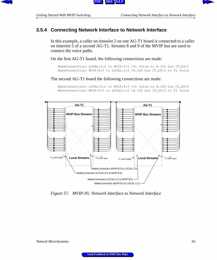
Getting Started With MVIP Switching Connecting Network Interface to Network Interface
IDX GLSTOC
3.5.4 Connecting Network Interface to Network Interface
In this example, a caller on timeslot 2 on one AG-T1 board is connected to a caller on timeslot 5 of a second AG-T1. Streams 8 and 9 of the MVIP bus are used to connect the voice paths.
On the first AG-T1 board, the following connections are made:
MakeConnection( LOCAL:0:2 to MVIP:9:5 )T1 voice to H.100 bus CT_D9:5MakeConnection( MVIP:8:5 to LOCAL:1:2 )H.100 bus CT_D8:5 to T1 voice
The second AG-T1 board the following connections are made:
MakeConnection( LOCAL:0:2 to MVIP:8:5 )T1 voice to H.100 bus CT_D8:5MakeConnection( MVIP:9:5 to LOCAL:1:2 )H.100 bus CT_D9:5 to T1 voice
Figure 57. MVIP-95: Network Interface to Network Interface
0123456789101112...
2425262728293031
0123456789
101112...
2425262728293031
MVIP Bus Streams
Local Streams10
T1 voice output T1 voice input
MakeConnection (MVIP:8:5 to LOCAL:1:2)
0123456789101112...
2425262728293031
0123456789101112...
2425262728293031
MVIP Bus Streams
Local Streams1
0T1 voice output T1 voice input
MakeConnection (LOCAL:0:2 to MVIP:8:5)
AG-T1 AG-T1
MakeConnection (LOCAL:0:2 to MVIP:9:5)
MakeConnection (MVIP:9:5 to LOCAL:1:2)
Natural MicroSystems 65
Send Feedback to NMS Doc Dept
Chapter 3 The Switch Block Model Getting Started With MVIP Switching
IDX GLSTOC
66 Natural MicroSystems
Send Feedback to NMS Doc Dept
IDX GLSTOC
Chapter 4
MVIP Clocking
4.1 Introduction 684.1.1 Telephony Bus Signals 68
4.2 Single Chassis Clock Configuration 694.2.1 H.100 Clock Configuration 704.2.2 MVIP-90 and H-MVIP Clock Configuration 72
4.3 Bus Clocking Fallback Behavior 734.3.1 H.100 Bus Primary Reference Trunk Failure 734.3.2 MVIP-90 and H-MVIP Bus Primary Reference Trunk Failure 74
4.4 Multi-Chassis Clock Configuration 754.4.1 MC1 Bus and MVIP Bus Clock Interaction 77
Natural MicroSystems 67
Send Feedback to NMS Doc Dept
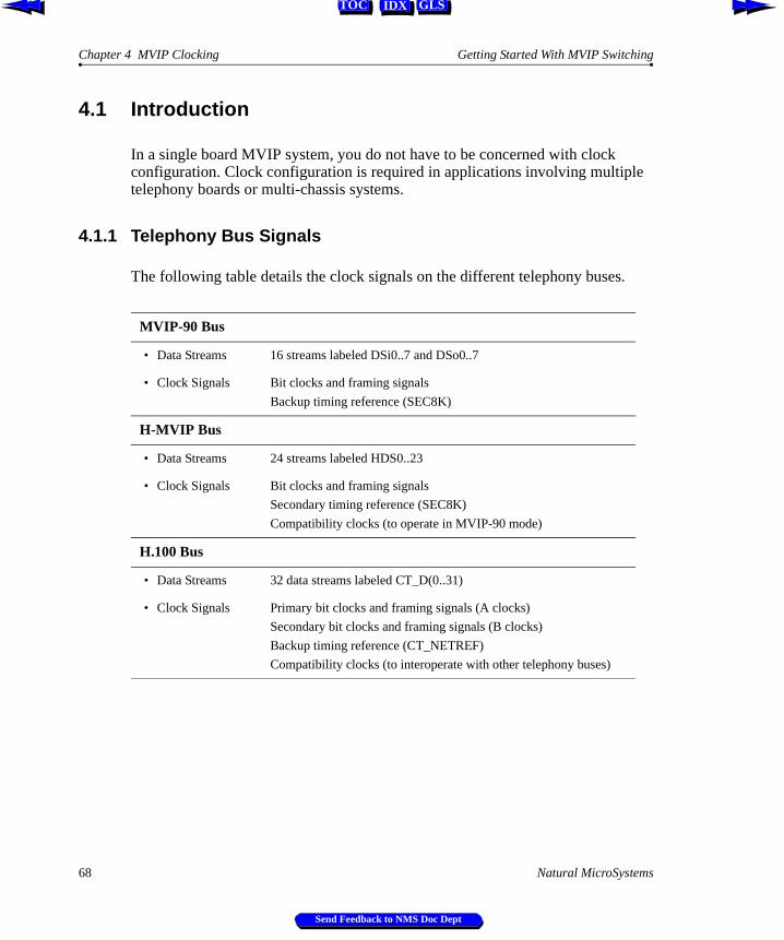
Chapter 4 MVIP Clocking Getting Started With MVIP Switching
IDX GLSTOC
4.1 Introduction
In a single board MVIP system, you do not have to be concerned with clock configuration. Clock configuration is required in applications involving multiple telephony boards or multi-chassis systems.
4.1.1 Telephony Bus Signals
The following table details the clock signals on the different telephony buses.
MVIP-90 Bus
• Data Streams 16 streams labeled DSi0..7 and DSo0..7
• Clock Signals Bit clocks and framing signals
Backup timing reference (SEC8K)
H-MVIP Bus
• Data Streams 24 streams labeled HDS0..23
• Clock Signals Bit clocks and framing signals
Secondary timing reference (SEC8K)
Compatibility clocks (to operate in MVIP-90 mode)
H.100 Bus
• Data Streams 32 data streams labeled CT_D(0..31)
• Clock Signals Primary bit clocks and framing signals (A clocks)
Secondary bit clocks and framing signals (B clocks)
Backup timing reference (CT_NETREF)
Compatibility clocks (to interoperate with other telephony buses)
68 Natural MicroSystems
Send Feedback to NMS Doc Dept
Getting Started With MVIP Switching Single Chassis Clock Configuration
IDX GLSTOC
4.2 Single Chassis Clock Configuration
In a system, one board drives the bus clock signals. The board that drives the bus clocks is called the bus clock master. All the timing signals are passed across the bus from the clock master. All other boards reference their clocks from the bus.
In a digital system, one or more of the boards in the system are connected by digital trunks to high-quality timing references within the public telephone network. Within the digital trunk interface, an 8 KHz reference is derived from the incoming signal. The clock master is phase-locked to this 8 KHz reference so that the long-term timing of the system matches that of the public telephone network. Typically, the board that is configured as the bus clock master also interfaces to the digital trunk that is being used as the network timing reference.
In an analog system with no digital telephone network interfaces, an analog board is configured as the bus clock master using the on-board oscillator to drive the clock signals.
Natural MicroSystems 69
Send Feedback to NMS Doc Dept
Chapter 4 MVIP Clocking Getting Started With MVIP Switching
IDX GLSTOC
4.2.1 H.100 Clock Configuration
Any board that contains an interface to an external communications network can be configured as a bus clock master. A board is configured as bus clock master either at installation or under software control. Figure 58 shows the H.100 clock master driving the A clocks.
Figure 58. H.100 Bus Clock Master
All other boards in an H.100 system are the bus clock slaves. Slaves reference their clocks from the bus.
Figure 59. Bus Clock Slaves
Clock Master
Network Board
telephonenetwork
Telephony Bus
A Clocks
B ClocksNETREF
Clock Master:drives A clocksreferencing telephonenetwork
Clock Master
Network Board
telephonenetwork
Telephony Bus
A Clocks
Clock Slave
B ClocksNETREF
Clock Slave:references A clocksdriven by bus clockmaster
70 Natural MicroSystems
Send Feedback to NMS Doc Dept
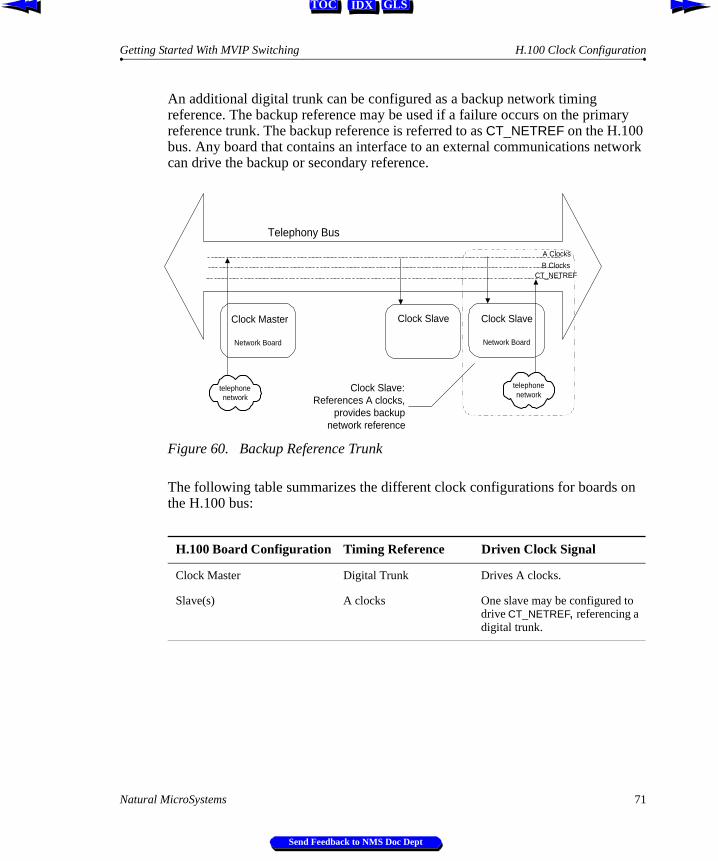
Getting Started With MVIP Switching H.100 Clock Configuration
IDX GLSTOC
An additional digital trunk can be configured as a backup network timing reference. The backup reference may be used if a failure occurs on the primary reference trunk. The backup reference is referred to as CT_NETREF on the H.100 bus. Any board that contains an interface to an external communications network can drive the backup or secondary reference.
Figure 60. Backup Reference Trunk
The following table summarizes the different clock configurations for boards on the H.100 bus:
H.100 Board Configuration Timing Reference Driven Clock Signal
Clock Master Digital Trunk Drives A clocks.
Slave(s) A clocks One slave may be configured to drive CT_NETREF, referencing a digital trunk.
Clock Master
Network Board
telephonenetwork
Telephony Bus
A Clocks
Clock Slave
Network Board
telephonenetwork
Clock Slave
B ClocksCT_NETREF
Clock Slave:References A clocks,
provides backupnetwork reference
Natural MicroSystems 71
Send Feedback to NMS Doc Dept
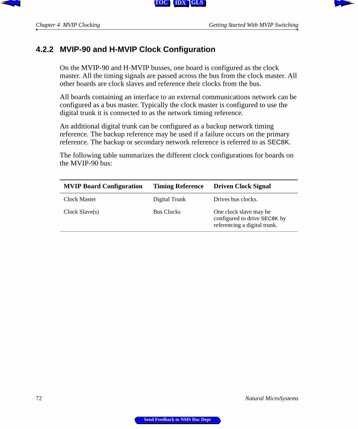
Chapter 4 MVIP Clocking Getting Started With MVIP Switching
IDX GLSTOC
4.2.2 MVIP-90 and H-MVIP Clock Configuration
On the MVIP-90 and H-MVIP busses, one board is configured as the clock master. All the timing signals are passed across the bus from the clock master. All other boards are clock slaves and reference their clocks from the bus.
All boards containing an interface to an external communications network can be configured as a bus master. Typically the clock master is configured to use the digital trunk it is connected to as the network timing reference.
An additional digital trunk can be configured as a backup network timing reference. The backup reference may be used if a failure occurs on the primary reference. The backup or secondary network reference is referred to as SEC8K.
The following table summarizes the different clock configurations for boards on the MVIP-90 bus:
MVIP Board Configuration Timing Reference Driven Clock Signal
Clock Master Digital Trunk Drives bus clocks.
Clock Slave(s) Bus Clocks One clock slave may be configured to drive SEC8K by referencing a digital trunk.
72 Natural MicroSystems
Send Feedback to NMS Doc Dept
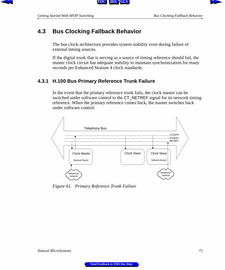
Getting Started With MVIP Switching Bus Clocking Fallback Behavior
IDX GLSTOC
4.3 Bus Clocking Fallback Behavior
The bus clock architecture provides system stability even during failure of external timing sources.
If the digital trunk that is serving as a source of timing reference should fail, the master clock circuit has adequate stability to maintain synchronization for many seconds per Enhanced Stratum 4 clock standards.
4.3.1 H.100 Bus Primary Reference Trunk Failure
In the event that the primary reference trunk fails, the clock master can be switched under software control to the CT_NETREF signal for its network timing reference. When the primary reference comes back, the master switches back under software control.
Figure 61. Primary Reference Trunk Failure
Clock Master
Network Board
telephonenetwork
Telephony Bus
A Clocks
Clock Slave
Network Board
telephonenetwork
Clock Slave
B ClocksNETREF
Natural MicroSystems 73
Send Feedback to NMS Doc Dept
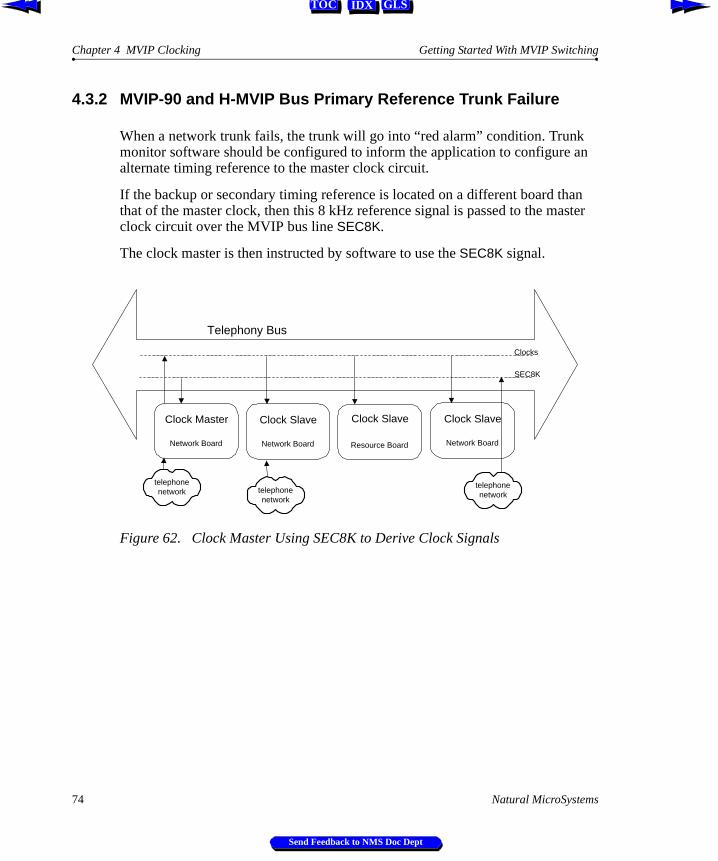
Chapter 4 MVIP Clocking Getting Started With MVIP Switching
IDX GLSTOC
an
an ster
4.3.2 MVIP-90 and H-MVIP Bus Primary Reference Trunk Failure
When a network trunk fails, the trunk will go into “red alarm” condition. Trunkmonitor software should be configured to inform the application to configure alternate timing reference to the master clock circuit.
If the backup or secondary timing reference is located on a different board ththat of the master clock, then this 8 kHz reference signal is passed to the maclock circuit over the MVIP bus line SEC8K.
The clock master is then instructed by software to use the SEC8K signal.
Figure 62. Clock Master Using SEC8K to Derive Clock Signals
Clock Master
Network Board
telephonenetwork
Telephony Bus
Clock Slave
Network Board
telephonenetwork
Clock Slave
Network Board
telephonenetwork
Clock Slave
Resource Board
Clocks
SEC8K
74 Natural MicroSystems
Send Feedback to NMS Doc Dept
Getting Started With MVIP Switching Multi-Chassis Clock Configuration
IDX GLSTOC
4.4 Multi-Chassis Clock Configuration
The clocks in a multi-chassis system must all be synchronized. This means that all boards in all chassis in the system must be driven by the same clock source.
There are three independent clock signals on the MC1 bus:
Æ MC1_8K (also called 8KREF)
Æ Left clock signals
Æ Right clock signals
In the Go-MVIP: MC1 Multi-Chassis MVIP Standard, the MC1_8K clock signal is called 8KREF. The MC1_8K (8KREF) clock signal provides the source clock signal ultimately used by all the MC1 boards. Either the left or right clock signal is configured to propagate this source clock signal to the MC1 bus. This clock line (left or right) is used to control the timing in the system. The unused signal line (left or right) may be configured as a backup clock signal.
Each MC1 board in the system is configured in one of the following clock modes:
Æ Primary master
The primary master synchronizes to the MC1_8K (8KREF) clock signal and generates either the left or right MC1 clocks. An MC1 system must have one and only one MC1 board configured as the primary master. This board will control the timing in the system.
Æ Secondary master
The secondary master is a backup to the primary master. It drives the clock that the primary master is not driving, synchronizing to the primary master. In the event of a primary clock failure, the secondary master supplies all the necessary clocking signals. An MC1 system can have one and only one MC1 interface board selected as secondary master. The secondary master is optional.
Æ Slave
All remaining MC1 boards in the system must be configured in slave mode. The slave boards monitor the designated primary master. In the event of a primary clock failure, the slave boards can be configured to automatically fall back to the secondary master for their clocking requirements.
Natural MicroSystems 75
Send Feedback to NMS Doc Dept
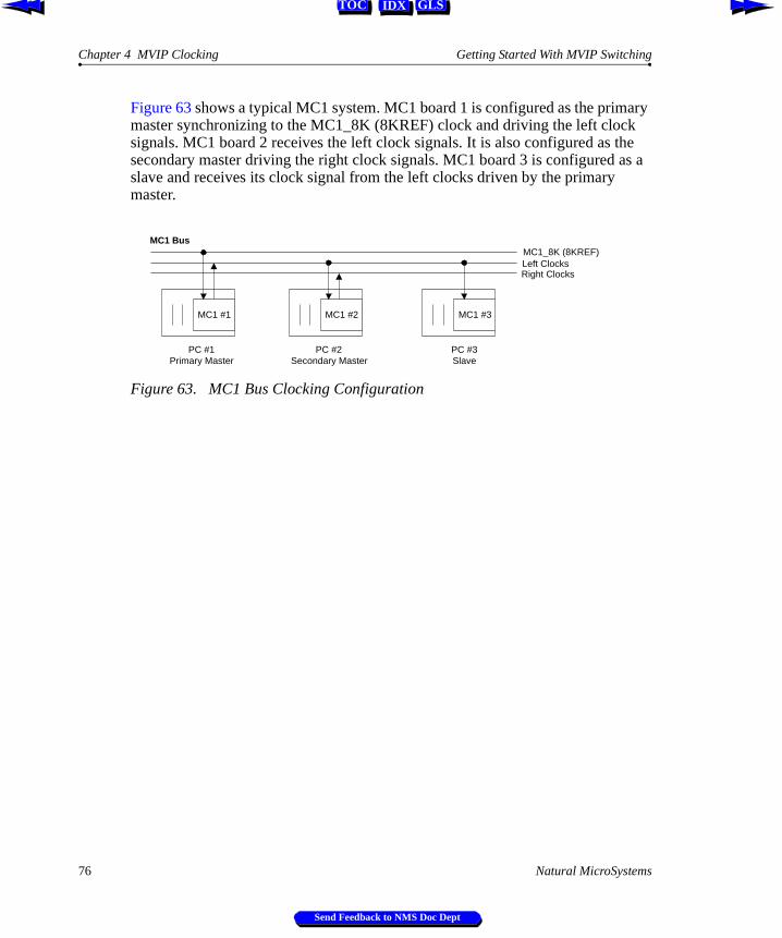
Chapter 4 MVIP Clocking Getting Started With MVIP Switching
IDX GLSTOC
Figure 63 shows a typical MC1 system. MC1 board 1 is configured as the primary master synchronizing to the MC1_8K (8KREF) clock and driving the left clock signals. MC1 board 2 receives the left clock signals. It is also configured as the secondary master driving the right clock signals. MC1 board 3 is configured as a slave and receives its clock signal from the left clocks driven by the primary master.
Figure 63. MC1 Bus Clocking Configuration
MC1 #1
PC #1Primary Master
MC1 #2
PC #2Secondary Master
MC1 #3
PC #3Slave
MC1_8K (8KREF)Left ClocksRight Clocks
MC1 Bus
76 Natural MicroSystems
Send Feedback to NMS Doc Dept
Getting Started With MVIP Switching MC1 Bus and MVIP Bus Clock Interaction
IDX GLSTOC
4.4.1 MC1 Bus and MVIP Bus Clock Interaction
The clocks in a multi-chassis system must all be synchronized. As shown in Figure 64, a single digital network interface board (e.g., AG-T1) is chosen as the overall system timing reference. This network board is configured to extract the 8 KHz telephone company reference and propagate it to the MVIP bus SEC8K signal.
The MC1 board in that chassis is configured to propagate the SEC8K signal to the MC1_8K (8KREF) signal on the MC1 bus for use by the primary master. The MC1 primary master references the MC1_8K (8KREF) signal and drives the left or right clocks.
All other MC1 boards receive their clock from the left or right clock signals. Each MC1 board typically drives the MVIP bus clocks in its PC chassis.
Note: While any MC1 board in the system can be configured to propagate the clock signal from the SEC8K line to the MC1_8K (8KREF) line, it is recommended that the primary master propagate the SEC8K signal.
Figure 64. MC1 Clock Propagation
Note: It is recommended that the SEC8K clock line for each MVIP bus be driven by a digital network board in its chassis for use as a backup timing reference.
SEC8KMC1_8K(8KREF)
Leftor
RightMVIPPSTN
MVIP
MVIP
digitalnetworkboard
MC1 Board(in samechassis asnetwork board)
MC1 Boardconfigured asprimarymaster formulti-chassissystem
An MC1board in each
PC chassisconfigured as
MVIP busclock master
Natural MicroSystems 77
Send Feedback to NMS Doc Dept

Chapter 4 MVIP Clocking Getting Started With MVIP Switching
IDX GLSTOC
78 Natural MicroSystems
Send Feedback to NMS Doc Dept
IDX GLSTOC
Chapter 5
MVIP-90 and H.100 Bus Interaction
5.1 Introduction 80
5.2 The MVIP Bus Adapter 80
Natural MicroSystems 79
Send Feedback to NMS Doc Dept
Chapter 5 MVIP-90 and H.100 Bus Interaction Getting Started With MVIP Switching
IDX GLSTOC
5.1 Introduction
The H.100 bus is a superset of the MVIP-90 bus. The streams on the H.100 bus may be configured to be clocked at the following speeds:
Æ 2 MHz - providing 32 timeslots
Æ 4 MHz - providing 64 timeslots
Æ 8 MHz - providing 128 timeslots
H.100 streams clocked at 2 MHz are compatible with the MVIP-90 bus.
Streams can be accessed by boards on both the H.100 bus and the MVIP-90 bus using MVIP Bus Adapter.
5.2 The MVIP Bus Adapter
The MVIP Bus Adapter is an adapter which connects the H.100 bus to the MVIP-90 bus in the same computer chassis (see Figure 65).
Figure 65. Connecting the H.100 Bus to MVIP-90 Bus
MVIP-90 cable
MVIP-90 Bus H.100 Bus
H.100 Bus Cable
MVIP Bus Adapter
H.100 Board
80 Natural MicroSystems
Send Feedback to NMS Doc Dept
Getting Started With MVIP Switching The MVIP Bus Adapter
IDX GLSTOC
The MVIP Bus Adapter allows boards connected to the H.100 bus to access the MVIP-90 bus and MVIP-90 boards to access the first 16 streams of the H.100 bus.
When connecting H.100 boards to the adapter, configure the first 16 streams on the bus for MVIP-90 mode. The H.100 streams running in MVIP-90 mode are clocked at 2 MHz, each having 32 timeslots.
Figure 66. MVIP Bus Adapter Stream Mappings
In a system with both H.100 boards and MVIP-90 boards, it is recommended that one of the H.100 boards be configured as the clock master.
Note: In order to use the clock fallback features in an MC1 system, the MC1 board must be configured as the MVIP bus clock master. In an MC1 system, H.100 boards are configured as clock slaves to the MVIP-90 bus. In this configuration, some H.100 bus streams are configured in MVIP-90 compatibility mode (clocked at 2 MHz) and are limited to 32 timeslots.
Note: If your system contains more than 6 AG-T1 or AG-E1 boards (revision D) connected to the H.100 bus using an MVIP bus adapter, you may experience clocking errors. Using more than 8 ISA MVIP boards with an adapter, regardless of board type, may also cause clocking problems.
.
.
.
.
.
.
CT_D0CT_D1CT_D2CT_D3CT_D4
CT_D13CT_D14CT_D15CT_D16CT_D17CT_D18CT_D19CT_D20
MVIP-90 Bus H.100 Bus
.
.
.CT_D29CT_D30CT_D31
H.100 Streamswith up to 128
timeslots
MVIP-90 Streamswith 32 timeslots
MVIPBus
Adaptor
DSo0DSi0DSo1DSi1DSo2
DSo7DSi7DSo6
Natural MicroSystems 81
Send Feedback to NMS Doc Dept
Chapter 5 MVIP-90 and H.100 Bus Interaction Getting Started With MVIP Switching
IDX GLSTOC
82 Natural MicroSystems
Send Feedback to NMS Doc Dept
IDX GLSTOC
Appendix A
Switching Examples
Introduction 84
Switching Example 84
Natural MicroSystems 83
Send Feedback to NMS Doc Dept
Appendix A Switching Examples Getting Started With MVIP Switching
IDX GLSTOC
Introduction
This appendix shows the switching commands for a typical switching application. The boards in the system are:
Switching Example
The following default switch connections are made:
.
Board Functionality
AG-T1 24 T1 channels with 24 ports of DSP resources
S Connect-24 24 operator workstation interfaces
AG-24 24 ports of DSP resources used for DTMF/tone generation and detection for the S Connect-24
Board Default Connections
AG-T1 Switch connections to connect the network interface voice and signaling streams to the on-board DSP resources.
S Connect-24 Switch connections to connect the operator workstation voice and signaling streams to the AG-24 DSP resources.
AG-24 MVIP-90: Voice data nailed up to stream 0; signaling data nailed up to stream 1.
MVIP-95: Voice data nailed up to streams 0 and 1; signaling data nailed up to streams 2 and 3.
84 Natural MicroSystems
Send Feedback to NMS Doc Dept
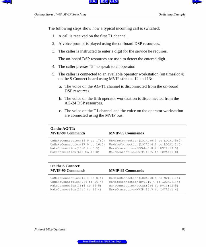
Getting Started With MVIP Switching Switching Example
IDX GLSTOC
t 4)
tion
The following steps show how a typical incoming call is switched:
1. A call is received on the first T1 channel.
2. A voice prompt is played using the on-board DSP resources.
3. The caller is instructed to enter a digit for the service he requires.
The on-board DSP resources are used to detect the entered digit.
4. The caller presses “5” to speak to an operator.
5. The caller is connected to an available operator workstation (on timesloon the S Connect board using MVIP streams 12 and 13:
a. The voice on the AG-T1 channel is disconnected from the on-boardDSP resources.
b. The voice on the fifth operator workstation is disconnected from theAG-24 DSP resources.
c. The voice on the T1 channel and the voice on the operator workstaare connected using the MVIP bus.
On the AG-T1:MVIP-90 Commands MVIP-95 Commands
UnMakeConnection(16:0 to 17:0)UnMakeConnection(17:0 to 16:0)MakeConnection(16:0 to 6:5)MakeConnection(6:5 to 16:0)
UnMakeConnection(LOCAL:0:0 to LOCAL:5:0)UnMakeConnection(LOCAL:4:0 to LOCAL:1:0)MakeConnection(LOCAL:0:0 to MVIP:13:5)MakeConnection(MVIP:12:5 to LOCAL:1:0)
On the S Connect:MVIP-90 Commands MVIP-95 Commands
UnMakeConnection(16:4 to 0:4)UnMakeConnection(0:4 to 16:4)MakeConnection(16:4 to 14:5)MakeConnection(14:5 to 16:4)
UnMakeConnection(LOCAL:0:4 to MVIP:1:4)UnMakeConnection(MVIP:0:4 to LOCAL:1:4)MakeConnection(LOCAL:0:4 to MVIP:12:5)MakeConnection(MVIP:13:5 to LOCAL:1:4)
Natural MicroSystems 85
Send Feedback to NMS Doc Dept
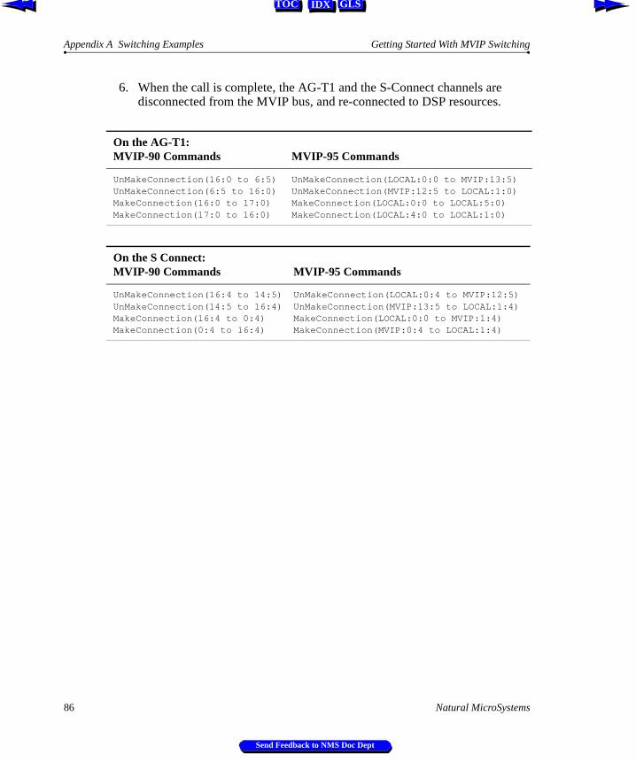
Appendix A Switching Examples Getting Started With MVIP Switching
IDX GLSTOC
6. When the call is complete, the AG-T1 and the S-Connect channels are disconnected from the MVIP bus, and re-connected to DSP resources.
On the AG-T1:MVIP-90 Commands MVIP-95 Commands
UnMakeConnection(16:0 to 6:5)UnMakeConnection(6:5 to 16:0)MakeConnection(16:0 to 17:0)MakeConnection(17:0 to 16:0)
UnMakeConnection(LOCAL:0:0 to MVIP:13:5)UnMakeConnection(MVIP:12:5 to LOCAL:1:0)MakeConnection(LOCAL:0:0 to LOCAL:5:0)MakeConnection(LOCAL:4:0 to LOCAL:1:0)
On the S Connect:MVIP-90 Commands MVIP-95 Commands
UnMakeConnection(16:4 to 14:5)UnMakeConnection(14:5 to 16:4)MakeConnection(16:4 to 0:4)MakeConnection(0:4 to 16:4)
UnMakeConnection(LOCAL:0:4 to MVIP:12:5)UnMakeConnection(MVIP:13:5 to LOCAL:1:4)MakeConnection(LOCAL:0:0 to MVIP:1:4)MakeConnection(MVIP:0:4 to LOCAL:1:4)
86 Natural MicroSystems
Send Feedback to NMS Doc Dept
IDX GLSTOC
Appendix B
Switch Implementation
Introduction 88
HMIC Switch 88HMIC Switching Restrictions 88
FMIC Switch 89FMIC Switching Restrictions 89
Digital Crosspoint Switches 91
Natural MicroSystems 87
Send Feedback to NMS Doc Dept
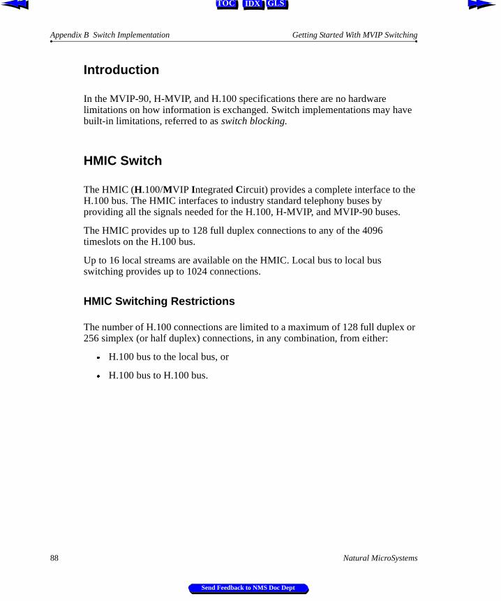
Appendix B Switch Implementation Getting Started With MVIP Switching
IDX GLSTOC
Introduction
In the MVIP-90, H-MVIP, and H.100 specifications there are no hardware limitations on how information is exchanged. Switch implementations may have built-in limitations, referred to as switch blocking.
HMIC Switch
The HMIC (H.100/MVIP Integrated Circuit) provides a complete interface to the H.100 bus. The HMIC interfaces to industry standard telephony buses by providing all the signals needed for the H.100, H-MVIP, and MVIP-90 buses.
The HMIC provides up to 128 full duplex connections to any of the 4096 timeslots on the H.100 bus.
Up to 16 local streams are available on the HMIC. Local bus to local bus switching provides up to 1024 connections.
HMIC Switching Restrictions
The number of H.100 connections are limited to a maximum of 128 full duplex or 256 simplex (or half duplex) connections, in any combination, from either:
Æ H.100 bus to the local bus, or
Æ H.100 bus to H.100 bus.
88 Natural MicroSystems
Send Feedback to NMS Doc Dept
Getting Started With MVIP Switching FMIC Switch
IDX GLSTOC
FMIC Switch
The FMIC (Flexible MVIP Interface Circuit) provides a complete enhanced-compliant interface to the MVIP-90 bus. The FMIC supports up to 128 full duplex connections to any of the 512 timeslots on the MVIP-90 bus.
FMIC Switching Restrictions
The MVIP-90 Switching Standard is designed to use full duplex streams. When making a full duplex connection using stream 0, the timeslot on DSo0 is used to receive input, and output is driven onto the same timeslot on DSi0. For example:
MakeConnection ( 0:3 to 2:6 ) /* connects DSo0:3 to DSi2:6 */MakeConnection ( 2:6 to 0:3 ) /* connects DSo2:3 to DSi0:6 */
The FMIC chip was built for implementing MVIP-90 switching. It has a direction bit in its connection memory for each timeslot, that selects either of the following modes:
Æ Send output to a timeslot on a DSi stream and receive input from the same timeslot on the corresponding DSo; or
Æ Receive input from a timeslot on a DSi and send output to the same timeslot on the corresponding DSo.
The FMIC cannot simultaneously send output to both DSi and DSo on the same timeslot on the same-numbered stream, and also cannot simultaneously receive input from both DSi and DSo on the same timeslot.
For example, the following simplex connection is made:
MakeConnection ( 0:3 to 2:6 ) /* connects DSo0:3 to DSi2:6 */
The FMIC establishes DSo0:3 as an input timeslot and DSi0:3 as an output timeslot. Even though there are no switch connections made to DSi0:3, the switch block cannot receive input from DSi0:3 because the direction is set in the FMIC by the switch command for DSo0:3.
When using the MVIP-95 switch model, a full duplex connection is:
MakeConnection ( 0:3 to 5:6 ) /* connects DSo0:3 to DSi2:6 */MakeConnection ( 4:6 to 1:3 ) /* connects DSo2:6 to DSi0:3 */
Natural MicroSystems 89
Send Feedback to NMS Doc Dept
Appendix B Switch Implementation Getting Started With MVIP Switching
IDX GLSTOC
When a connection is made using stream 0 timeslot 3, the direction is set for timeslot 3 on stream 1. Stream 0 corresponds to DSo0, and stream 1 corresponds to DSi0 (see Figure 67).
In most applications, this switch blocking is completely invisible. However, for any board with an FMIC switch, you cannot connect the local DSP resources to the local network interfaces over the MVIP bus. Those connections must be made using the local streams. Likewise, you cannot connect two trunk channels on the same board over the MVIP bus.
Making a connection of any type involving a timeslot on an MVIP stream establishes the direction for that timeslot pair. The direction may not be changed until all connections involving the timeslot have been broken.
If you make arbitrary simplex connections, you may encounter blocking from an unavailable connection, where the direction bit on the connection has already been set in the opposite direction.
Note that there is no direction associated with local streams.
90 Natural MicroSystems
Send Feedback to NMS Doc Dept
Getting Started With MVIP Switching Digital Crosspoint Switches
IDX GLSTOC
Figure 67. MVIP-90 and MVIP-95 Stream Mapping
Digital Crosspoint Switches
A MVIP-90 standard-compliant interface can be implemented with four digital crosspoint switches.
Connections between local streams are not supported in a MVIP-90 standard-compliant switch. Local stream to local stream connections must be made over the MVIP bus.
MVIP Bus: DSo5MVIP-90: Stream 5 - MVIP-95: Stream 10
MVIP Bus: DSo4MVIP-90: Stream 4 - MVIP-95: Stream 8
MVIP Bus: DSo3MVIP-90: Stream 3 - MVIP-95: Stream 6
MVIP Bus: DSo2MVIP-90: Stream 2 - MVIP-95: Stream 4
MVIP Bus: DSo1MVIP-90: Stream 1 - MVIP-95: Stream 2
MVIP Bus: DSi4MVIP-90: Stream 4 - MVIP-95: Stream 9
MVIP Bus: DSi3MVIP-90: Stream 3 - MVIP-95: Stream 7
MVIP Bus: DSi2MVIP-90: Stream 2 - MVIP-95: Stream 5
MVIP Bus: DSi1MVIP-90: Stream 1 - MVIP-95: Stream 3
MVIP Bus: DSi0MVIP-90: Stream 0 - MVIP-95: Stream 1
MVIP Bus (DSo 0..7)
MVIP Bus (DSi 0..7)
1514
15
Switch Block
MVIP BusStreams
MVIP Bus: DSo1MVIP-90: Stream 9 - MVIP-95: Stream 2
MVIP Bus: DSo0MVIP-90: Stream 8 - MVIP-95: Stream 0
MVIP Bus: DSi7MVIP-90: Stream 7 - MVIP-95: Stream 15
MVIP Bus: DSi6MVIP-90: Stream 6 - MVIP-95: Stream 13
MVIP Bus: DSi5MVIP-90: Stream 5 - MVIP-95: Stream 11
MVIP Bus: DSo2MVIP-90: Stream 10 - MVIP-95: Stream 4
MVIP Bus: DSo3MVIP-90: Stream 11 - MVIP-95: Stream 6
MVIP Bus: DSo4MVIP-90: Stream 12 - MVIP-95: Stream 8
MVIP Bus: DSo5MVIP-90: Stream 13 - MVIP-95: Stream 10
MVIP Bus: DSo6MVIP-90: Stream 14 - MVIP-95: Stream 12
MVIP Bus: DSo7MVIP-90: Stream 15 - MVIP-95: Stream 14
MVIP Bus: DSo0MVIP-90: Stream 0 - MVIP-95: Stream 0
MVIP Bus: DSi1MVIP-90: Stream 9 - MVIP-95: Stream 3
MVIP Bus: DSi0MVIP-90: Stream 8 - MVIP-95: Stream 1
MVIP Bus: DSo7MVIP-90: Stream 7 - MVIP-95: Stream 14
MVIP Bus: DSo6MVIP-90: Stream 6 - MVIP-95: Stream 12
MVIP Bus: DSi2MVIP-90: Stream 10 - MVIP-95: Stream 5
MVIP Bus: DSi3MVIP-90: Stream 11 - MVIP-95: Stream 7
MVIP Bus: DSi4MVIP-90: Stream 12 - MVIP-95: Stream 9
MVIP Bus: DSi5MVIP-90: Stream 13 - MVIP-95: Stream 11
MVIP Bus: DSi6MVIP-90: Stream 14 - MVIP-95: Stream 13
MVIP Bus: DSi7MVIP-90: Stream 15 - MVIP-95: Stream 15
Natural MicroSystems 91
Send Feedback to NMS Doc Dept
Appendix B Switch Implementation Getting Started With MVIP Switching
IDX GLSTOC
92 Natural MicroSystems
Send Feedback to NMS Doc Dept
IDX GLSTOC
Index
AAG-24 board 29, 31, 33AG-T1 board 30–31, 33, 45AG-T1 MVIP-90 switch model48AG-T1 MVIP-95 switch model60analog line signaling10analog network interfaces24
Bbackup clock signal68, 71–72bus clock master69bus speed10, 28
CCAS 10CCS 10channel associated signaling10clock signals68clocking
analog system69digital system69stability 73
common channel signaling10connection
duplex 16duplex with signaling16simplex 16
CT_NETREF clock signal68, 71, 73
Ddigital network interfaces24DSP resources
definition 25input 39nailed up29, 40output 39
duplex connection11–12, 16
Natural MicroSystems
Send Feedback to NMS
duplex with signaling connection16
EE1
signaling 10standard10
ECTF 6
Fforward connection44frame
definition of 9length of 10
frame length28full-duplex connection39, 41, 57
GGO-MVIP 6
HH.100 bus
A clocks 68, 70B clocks 68bus stream mapping55clock configuration71clock failure 73clock master70, 81clock signals68clock slaves70clock speeds80data streams54MVIP-95 switch model37
H.100 standard23, 28H-MVIP bus
bus stream mapping55clock signals68data streams54
93
Doc Dept
Index Getting Started With MVIP Switching
IDX GLSTOC
MVIP-95 switch model 37H-MVIP standard 23, 28
Iinternal bus 26, 30, 36, 54ISDN signaling 10
Llocal bus 26, 30, 36, 54local resources 26, 30, 36, 54
MMC1
clock synchronization 77clocking 75definition 32system clocking 81
MC1 busexample 33
multi-chassis switching 32Multi-Vendor Integration Protocol (MVIP) 7, 22MVIP Bus Adapter 80MVIP standard
evolution 23overview 22
MVIP-90signaling data 38voice data 38
MVIP-90 busaddressing 41bus stream mapping 55clock configuration 72clock failure 74clock master 72, 77, 81clock signals 68clock slaves 72clock speeds 80data streams 38local resources 38MVIP-95 switch model 37physical wires 38stream number 41
MVIP-90 standard 23, 28MVIP-90 switch model 37
94
Send Feedb
MVIP-95local bus 54MC1 bus 54MVIP bus 54signaling data 56voice data 56
MVIP-95 standard 23MVIP-95 stream convention 56MVIP-95 switch model 37, 54
Nnetwork interfaces
analog 24definition 24digital 24input 39on boards 30output 39
Nyquist’s theorem8
Ppattern 15PBXs 7PC bus limitations27port
definition of 29
Rreceive stream13resource boards29reverse connection44–46
Ssampling rate10SEC8K clock signal68, 72, 74, 77serial data streams28signal processing8signaling
analog line10E1 10ISDN 10T1 10
signaling data10, 24simplex connection16
Natural MicroSystems
ack to NMS Doc Dept
Getting Started With MVIP Switching Index
IDX GLSTOC
single-board switching 26speech frequency 8speech sampling 8start-of-frame signal 10stream speed 80switch
definition 25switch block
addressing 36definition 14input 14operation 15output 14
switch block modeldefinition of 36local resources 36
switch commandnetwork interface 43
switch connectiondefinition 12DSP resource to network interface 31, 39, 58forward connection 44local 26network interface to network interface 44, 59reverse connection 44–46
switching exampleMVIP-90 local connection50MVIP-90 network interface to DSP
resource51–52MVIP-90 network interface to network
interface 53MVIP-95 local connection62MVIP-95 network interface to DSP
resource63–64MVIP-95 network interface to network
interface 65switching hierarchy34switching overview7
TT1
signaling 10standard10
TDM 9, 12, 24telecommunications7
Natural MicroSystems
Send Feedback to NMS
telephony busclock signals28, 68creation 27data streams28, 55evolution 23switching 27
terminusdefinition of 54
time division multiplexing9, 12, 24timeslot
definition of 9transmit stream13tri-state 15
Vvoice data8voice path
receive 11transmit 11
voice sampling8–9
95
Doc Dept
Index Getting Started With MVIP Switching
IDX GLSTOC
96
Send Feedb
Natural MicroSystems
ack to NMS Doc Dept