Embed Size (px)
Citation preview

ANSYS, Inc.Southpointe2600 ANSYS DriveCanonsburg, PA 15317 [email protected] http://www.ansys.com (T) 724-746-3304(F) 724-514-9494
March 2015ANSYS Electromagnetics Suite 16.x
ANSYS, Inc. is certified to ISO9001:2008.
Getting Started with HFSS™
Probe Feed Patch Antenna

Copyright and Trademark Information
© 2015 SAS IP, Inc. All rights reserved. Unauthorized use, distribution or duplication is prohibited.
ANSYS, HFSS, and Optimetrics and any and all ANSYS, Inc. brand, product, service and feature names, logos and slogans are registered trademarks or trademarks of ANSYS, Inc. or its subsidiaries in the United States or other countries. All other brand, product, service and feature names or trademarks are the property of their respective owners.
Disclaimer Notice
THIS ANSYS SOFTWARE PRODUCT AND PROGRAM DOCUMENTATION INCLUDE TRADE SECRETS AND ARE CONFIDENTIAL AND PROPRIETARY PRODUCTS OF ANSYS, INC., ITS SUBSIDIAR IES, OR LICENSORS. The software products and documentation are furnished by ANSYS, Inc., its subsidiaries, or affiliates under a software license agreement that contains provisions concerning non-disclosure, copying, length and nature of use, compliance with exporting laws, warranties, disclaimers, limitations of liability, and remedies, and other provisions. The software products and documentation may be used, disclosed, transferred, or copied only in accordance with the terms and conditions of that software license agreement.
ANSYS, Inc. is certified to ISO 9001:2008.
U.S. Government Rights
For U.S. Government users, except as specifically granted by the ANSYS, Inc. software license agreement, the use, duplication, or disclosure by the United States Government is subject to restrictions stated in the ANSYS, Inc. software license agreement and FAR 12.212 (for non-DOD licenses).
Third-Party Software
See the legal information in the product help files for the complete Legal Notice for ANSYS proprietary software and third-party software. If you are unable to access the Legal Notice, please contact ANSYS, Inc.
Published in the U.S.A.
ANSYS Electromagnetics Suite 16.0 - © SAS IP, Inc. All rights reserved. - Contains proprietary and confidential informationof ANSYS, Inc. and its subsidiaries and affiliates.
ii

Conventions Used in this Guide
Please take a moment to review how instructions and other useful information are presented in this guide.
• Procedures are presented as numbered lists. A single bullet indicates that the procedure has only one step.Bold type is used for the following:
- Keyboard entries that should be typed in their entirety exactly as shown. For example, “copy file1” means the word copy must be typed, then a space must be typed, and then file1 must be typed.
- On-screen prompts and messages, names of options and text boxes, and menu commands. Menu commands are often separated by carats. For example, “click HFSS>Exci-tations>Assign>Wave Port.”
- Labeled keys on the computer keyboard. For example, “Press Enter” means to press the key labeled Enter.
• Italic type is used for the following:
- Emphasis.
- The titles of publications.
- Keyboard entries when a name or a variable must be typed in place of the words in italics. For example, “copy file name” the word copy must be typed, then a space must be typed, and then name of the file must be typed.
• The plus sign (+) is used between keyboard keys to indicate that you should press the keys at the same time. For example, “Press Shift+F1” means to press the Shift key and the F1 key at the same time.
• Toolbar buttons serve as shortcuts for executing commands. Toolbar buttons are displayed after the command they execute. For example,
• “On the Draw menu, click Line ” means that you can click the Draw Line toolbar button to execute the Line command.
iii
ANSYS Electromagnetics Suite 16.0 - © SAS IP, Inc. All rights reserved. - Contains proprietary and confidential informationof ANSYS, Inc. and its subsidiaries and affiliates.

Getting Help: ANSYS Technical Support
For information about ANSYS Technical Support, go to the ANSYS corporate Support website, www.ansys.com/Support. You can also contact your ANSYS account manager in order to obtain this information.
All ANSYS software files are ASCII text and can be sent conveniently by e-mail. When reporting difficulties, it is extremely helpful to include very specific information about what steps were taken or what stages the simulation reached, including software files as applicable. This allows more rapid and effective debugging.
Help Menu
To access online help from the HFSS menu bar, click Help and select from the menu:
Contents - click here to open the contents of the online help.
Search - click here to open the search function of the online help.
Index - click here to open the index of the online help.
Context-Sensitive Help
To access online help from the HFSS user interface, do one of the following:
• To open a help topic about a specific HFSS menu command, press Shift+F1, and then click the command or toolbar icon.
• To open a help topic about a specific HFSS dialog box, open the dialog box, and then press F1.
iv
ANSYS Electromagnetics Suite 16.0 - © SAS IP, Inc. All rights reserved. - Contains proprietary and confidential informationof ANSYS, Inc. and its subsidiaries and affiliates.

v
ANSYS Electromagnetics Suite 16.0 - © SAS IP, Inc. All rights reserved. - Contains proprietary and confidential informationof ANSYS, Inc. and its subsidiaries and affiliates.

Table of Contents
1. IntroductionSample Project: Patch Antenna . . . . . . . . . . . . . 1-2
2. Set Up The ProjectLaunch HFSS . . . . . . . . . . . . . . . . . . . . . . . . . . . 2-2Set Tool Options . . . . . . . . . . . . . . . . . . . . . . . . 2-2Insert HFSS design . . . . . . . . . . . . . . . . . . . . . . 2-3
Set Model Units (cm) . . . . . . . . . . . . . . . . . . . . 2-3
Set Solution Type (Terminal) . . . . . . . . . . . . . . 2-4
3. Set Up The ProjectCreate Substrate . . . . . . . . . . . . . . . . . . . . . . . . 3-2
Create Infinite Ground . . . . . . . . . . . . . . . . . . . 3-4
Assign Perfect E boundary to the Ground . . . 3-5
Create Infinite Ground Cut Out . . . . . . . . . . . . 3-6
Complete the Infinite Ground . . . . . . . . . . . . . 3-7
To complete the ring . . . . . . . . . . . . . . . . . . . . 3-7
Create Patch . . . . . . . . . . . . . . . . . . . . . . . . . . 3-8
Assign a Perfect E boundary to the Patch . . . 3-9
Create the Coax . . . . . . . . . . . . . . . . . . . . . . . . . 3-10Create the Coax Pin . . . . . . . . . . . . . . . . . . . . 3-11
Assign Excitation . . . . . . . . . . . . . . . . . . . . . . . 3-13
Contents-1
ANSYS Electromagnetics Suite 16.0 - © SAS IP, Inc. All rights reserved. - Contains proprietary and confidential informationof ANSYS, Inc. and its subsidiaries and affiliates.
Getting Started with HFSS: A Probe Feed Patch Antenna
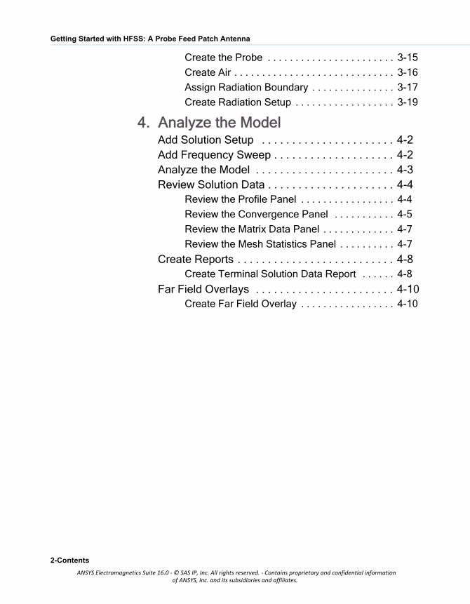
Create the Probe . . . . . . . . . . . . . . . . . . . . . . . 3-15
Create Air . . . . . . . . . . . . . . . . . . . . . . . . . . . . . 3-16
Assign Radiation Boundary . . . . . . . . . . . . . . . 3-17
Create Radiation Setup . . . . . . . . . . . . . . . . . . 3-19
4. Analyze the ModelAdd Solution Setup . . . . . . . . . . . . . . . . . . . . . . 4-2Add Frequency Sweep . . . . . . . . . . . . . . . . . . . . 4-2Analyze the Model . . . . . . . . . . . . . . . . . . . . . . . 4-3Review Solution Data . . . . . . . . . . . . . . . . . . . . . 4-4
Review the Profile Panel . . . . . . . . . . . . . . . . . 4-4
Review the Convergence Panel . . . . . . . . . . . 4-5
Review the Matrix Data Panel . . . . . . . . . . . . . 4-7
Review the Mesh Statistics Panel . . . . . . . . . . 4-7
Create Reports . . . . . . . . . . . . . . . . . . . . . . . . . . 4-8Create Terminal Solution Data Report . . . . . . 4-8
Far Field Overlays . . . . . . . . . . . . . . . . . . . . . . . 4-10Create Far Field Overlay . . . . . . . . . . . . . . . . . 4-10
2-Contents
ANSYS Electromagnetics Suite 16.0 - © SAS IP, Inc. All rights reserved. - Contains proprietary and confidential informationof ANSYS, Inc. and its subsidiaries and affiliates.
1 Introduction
This document is intended as supplementary material to HFSS for beginners and advanced users. It includes instructions to create, simulate, and analyze a probe feed patch antenna.
This chapter contains the following topics: Sample Project - Probe Feed Patch Antenna
Introduction 1-1
ANSYS Electromagnetics Suite 16.0 - © SAS IP, Inc. All rights reserved. - Contains proprietary and confidential informationof ANSYS, Inc. and its subsidiaries and affiliates.
Getting Started with HFSS: Probe Feed Patch Antenna
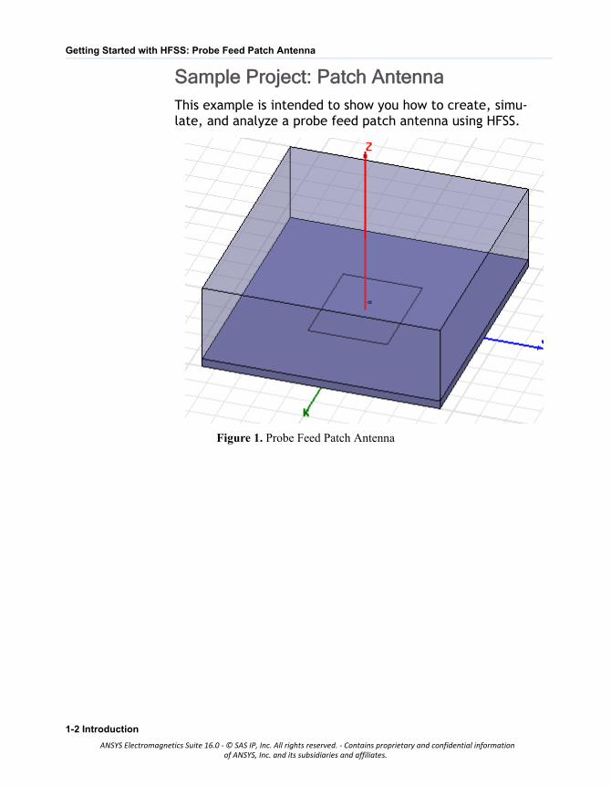
Sample Project: Patch AntennaThis example is intended to show you how to create, simu-late, and analyze a probe feed patch antenna using HFSS.
Figure 1. Probe Feed Patch Antenna
1-2 Introduction
ANSYS Electromagnetics Suite 16.0 - © SAS IP, Inc. All rights reserved. - Contains proprietary and confidential informationof ANSYS, Inc. and its subsidiaries and affiliates.
2 Set Up The Project
This chapter contains the following topics: Launch HFSS Set Tool Options Insert HFSS design Set Model Units (cm) Set Solution Type (Terminal)
Set Up The Project 2-1
ANSYS Electromagnetics Suite 16.0 - © SAS IP, Inc. All rights reserved. - Contains proprietary and confidential informationof ANSYS, Inc. and its subsidiaries and affiliates.

Getting Started with HFSS: Probe Feed Patch Antenna
Launch HFSS
1 Go to Windows Start > All Programs > ANSYS Elecromag-
netics > ANSYS Electronics Desktop to launch the appli-
cation.
Figure 1. ANSYS Electronics Desktop appears
Note If the application does not list the folder, go to File and click New. If the Project Manager window does not appear, go to View and enable it.
2-2 Set Up The Project
ANSYS Electromagnetics Suite 16.0 - © SAS IP, Inc. All rights reserved. - Contains proprietary and confidential informationof ANSYS, Inc. and its subsidiaries and affiliates.

Getting Started with HFSS: Probe Feed Patch Antenna
Set Tool OptionsVerify the options under the Tools menu as follows:1 Click Tools>Options>HFSS Options.
The HFSS Options dialog box appears.
Figure 2. Assignment Options
2 On the General tab ensure all Assignment Options are checked and click OK to close the dialog box.
3 Click Tools>Options>Modeler Options.
The Modeler Options dialog box appears.
4 On the Operation tab check Automatically cover closed polylines.
5 On the Drawing tab check Edit properties of new primi-tives and click OK.
Note This option causes a Properties dialog box to appear whenever you create a new object.
Insert HFSS designThe icon below represents the Insert HFSS design (IHd) option.
Figure 3. IHd
1 Expand the project tree.
2 Click Insert HFSS Design on the toolbar to include it in the project or got to the Project menu and select Insert HFSS Design.
Note Inclusion of IHd modifies the project and hence the asterisk appears on ProjectN.
Set Up The Project 2-3
ANSYS Electromagnetics Suite 16.0 - © SAS IP, Inc. All rights reserved. - Contains proprietary and confidential informationof ANSYS, Inc. and its subsidiaries and affiliates.
Getting Started with HFSS: Probe Feed Patch Antenna
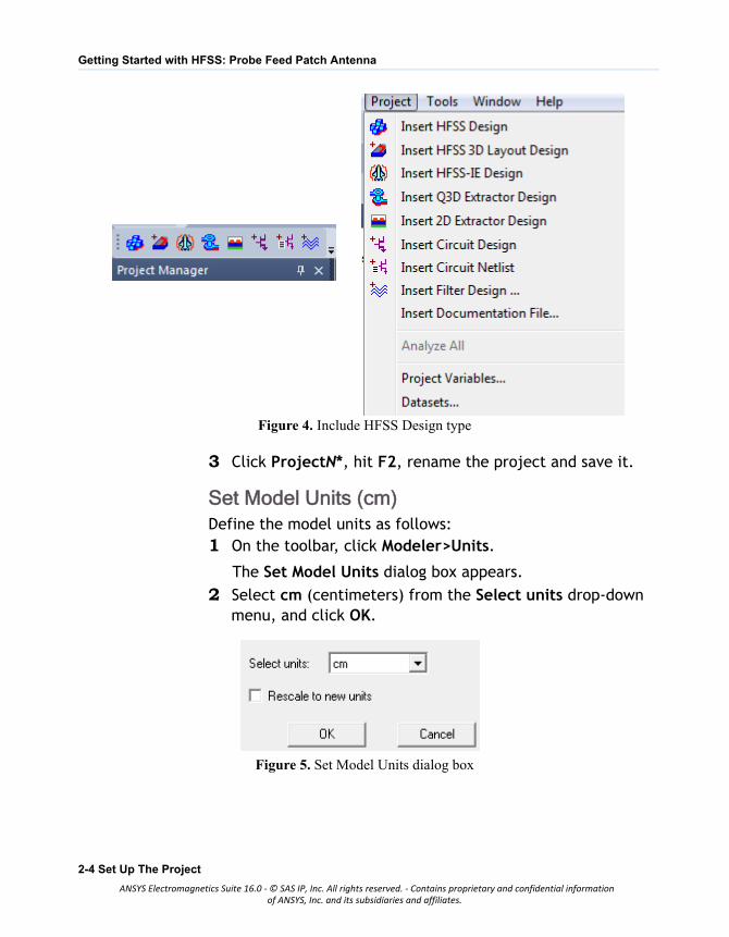
Figure 4. Include HFSS Design type
3 Click ProjectN*, hit F2, rename the project and save it.
Set Model Units (cm)Define the model units as follows:1 On the toolbar, click Modeler>Units.
The Set Model Units dialog box appears.
2 Select cm (centimeters) from the Select units drop-down menu, and click OK.
Figure 5. Set Model Units dialog box
2-4 Set Up The Project
ANSYS Electromagnetics Suite 16.0 - © SAS IP, Inc. All rights reserved. - Contains proprietary and confidential informationof ANSYS, Inc. and its subsidiaries and affiliates.

Getting Started with HFSS: Probe Feed Patch Antenna
Set Solution Type (Terminal)Specify the design’s solution type as follows:1 Right click HFSSDesign1(DrivenModal) and select Solution
Type from the shortcut menu.
The Solution Type dialog box appears.
Figure 6. Solution Type dialog box
2 Select Driven Terminal and click OK.
Note Driven Terminal calculates the terminal-based S-parameters of multi-conductor transmission line ports. The S-matrix solutions will be expressed in terms of terminal voltages and currents.
Set Up The Project 2-5
ANSYS Electromagnetics Suite 16.0 - © SAS IP, Inc. All rights reserved. - Contains proprietary and confidential informationof ANSYS, Inc. and its subsidiaries and affiliates.

3 Set Up The Project
This chapter contains the following topics: Create Substrate Create Infinite Ground Assign Perfect E Boundary to the Ground Create Infinite Ground Cut-Out Complete the Infinite Ground Complete the Ring Create Patch Assign Perfect E Boundary to the Patch Create the Coax Create the Coax Pin Assign Excitation Create the Probe Create Air Body Assign Radiation Boundary Create Radiation Setup
Set Up The Project 3-1
ANSYS Electromagnetics Suite 16.0 - © SAS IP, Inc. All rights reserved. - Contains proprietary and confidential informationof ANSYS, Inc. and its subsidiaries and affiliates.
Getting Started with HFSS: Probe Feed Patch Antenna
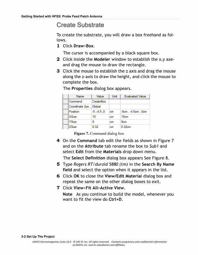
Create Substrate
To create the substrate, you will draw a box freehand as fol-lows.1 Click Draw>Box.
The cursor is accompanied by a black square box.
2 Click inside the Modeler window to establish the x,y axe-and drag the mouse to draw the rectangle.
3 Click the mouse to establish the z axis and drag the mouse along the z-axis to draw the height, and click the mouse to complete the box.
The Properties dialog box appears.
Figure 7. Command dialog box
4 On the Command tab edit the fields as shown in Figure 7 and on the Attribute tab rename the box to Sub1 and select Edit from the Materials drop down menu.
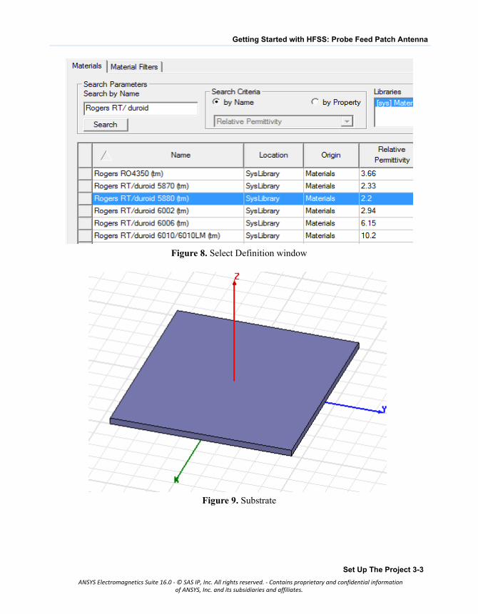
The Select Definition dialog box appears See Figure 8.
5 Type Rogers RT/duroid 5880 (tm) in the Search By Name field and select the option when it appears in the list.
6 Click OK to close the View/Edit Material dialog box and repeat the same on the other dialog boxes to exit.
7 Click View>Fit All>Active View.
Note As you continue to build the model, whenever you want to fit the view do Ctrl+D.
3-2 Set Up The Project
ANSYS Electromagnetics Suite 16.0 - © SAS IP, Inc. All rights reserved. - Contains proprietary and confidential informationof ANSYS, Inc. and its subsidiaries and affiliates.
Getting Started with HFSS: Probe Feed Patch Antenna
Figure 8. Select Definition window
Figure 9. Substrate
Set Up The Project 3-3
ANSYS Electromagnetics Suite 16.0 - © SAS IP, Inc. All rights reserved. - Contains proprietary and confidential informationof ANSYS, Inc. and its subsidiaries and affiliates.
Getting Started with HFSS: Probe Feed Patch Antenna
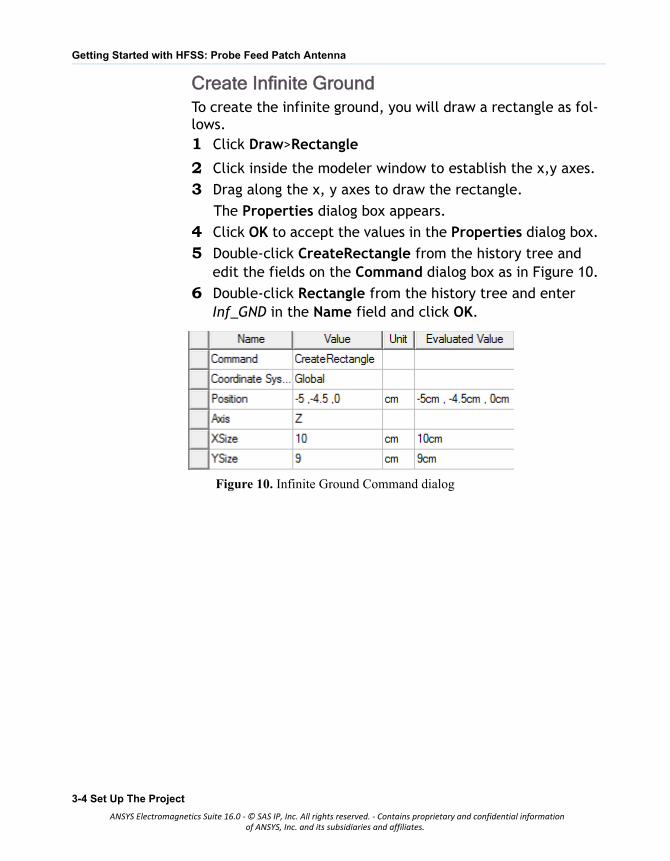
Create Infinite GroundTo create the infinite ground, you will draw a rectangle as fol-lows.1 Click Draw>Rectangle
2 Click inside the modeler window to establish the x,y axes.
3 Drag along the x, y axes to draw the rectangle.
The Properties dialog box appears.
4 Click OK to accept the values in the Properties dialog box.
5 Double-click CreateRectangle from the history tree and edit the fields on the Command dialog box as in Figure 10.
6 Double-click Rectangle from the history tree and enter Inf_GND in the Name field and click OK.
Figure 10. Infinite Ground Command dialog
3-4 Set Up The Project
ANSYS Electromagnetics Suite 16.0 - © SAS IP, Inc. All rights reserved. - Contains proprietary and confidential informationof ANSYS, Inc. and its subsidiaries and affiliates.
Getting Started with HFSS: Probe Feed Patch Antenna
.
Figure 11. Infinite Ground plane
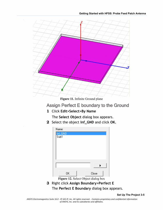
Assign Perfect E boundary to the Ground1 Click Edit>Select>By Name
The Select Object dialog box appears.
2 Select the object Inf_GND and click OK..
Figure 12. Select Object dialog box
3 Right click Assign Boundary>Perfect E
The Perfect E Boundary dialog box appears.
Set Up The Project 3-5
ANSYS Electromagnetics Suite 16.0 - © SAS IP, Inc. All rights reserved. - Contains proprietary and confidential informationof ANSYS, Inc. and its subsidiaries and affiliates.
Getting Started with HFSS: Probe Feed Patch Antenna
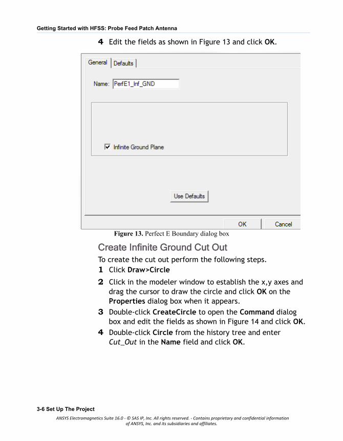
4 Edit the fields as shown in Figure 13 and click OK.
Figure 13. Perfect E Boundary dialog box
Create Infinite Ground Cut OutTo create the cut out perform the following steps.1 Click Draw>Circle
2 Click in the modeler window to establish the x,y axes and drag the cursor to draw the circle and click OK on the Properties dialog box when it appears.
3 Double-click CreateCircle to open the Command dialog box and edit the fields as shown in Figure 14 and click OK.
4 Double-click Circle from the history tree and enter Cut_Out in the Name field and click OK.
3-6 Set Up The Project
ANSYS Electromagnetics Suite 16.0 - © SAS IP, Inc. All rights reserved. - Contains proprietary and confidential informationof ANSYS, Inc. and its subsidiaries and affiliates.
Getting Started with HFSS: Probe Feed Patch Antenna
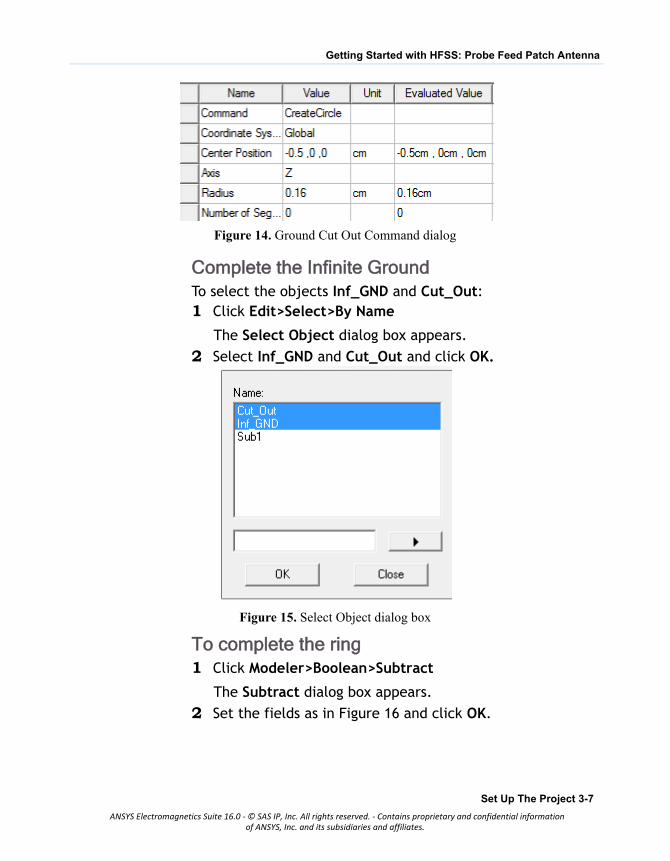
Figure 14. Ground Cut Out Command dialog
Complete the Infinite GroundTo select the objects Inf_GND and Cut_Out:1 Click Edit>Select>By Name
The Select Object dialog box appears.
2 Select Inf_GND and Cut_Out and click OK.
Figure 15. Select Object dialog box
To complete the ring1 Click Modeler>Boolean>Subtract
The Subtract dialog box appears.
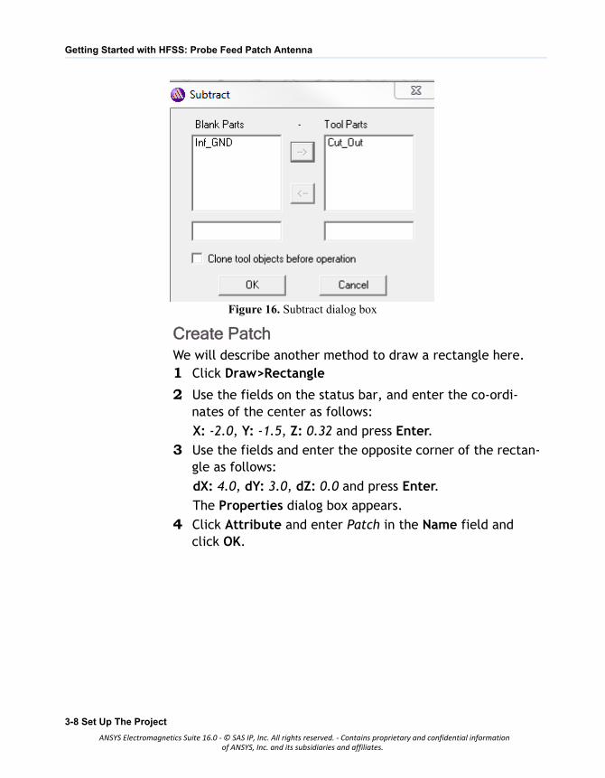
2 Set the fields as in Figure 16 and click OK.
Set Up The Project 3-7
ANSYS Electromagnetics Suite 16.0 - © SAS IP, Inc. All rights reserved. - Contains proprietary and confidential informationof ANSYS, Inc. and its subsidiaries and affiliates.
Getting Started with HFSS: Probe Feed Patch Antenna
Figure 16. Subtract dialog box
Create PatchWe will describe another method to draw a rectangle here.1 Click Draw>Rectangle
2 Use the fields on the status bar, and enter the co-ordi-nates of the center as follows:
X: -2.0, Y: -1.5, Z: 0.32 and press Enter.
3 Use the fields and enter the opposite corner of the rectan-gle as follows:
dX: 4.0, dY: 3.0, dZ: 0.0 and press Enter.
The Properties dialog box appears.
4 Click Attribute and enter Patch in the Name field and click OK.
3-8 Set Up The Project
ANSYS Electromagnetics Suite 16.0 - © SAS IP, Inc. All rights reserved. - Contains proprietary and confidential informationof ANSYS, Inc. and its subsidiaries and affiliates.
Getting Started with HFSS: Probe Feed Patch Antenna
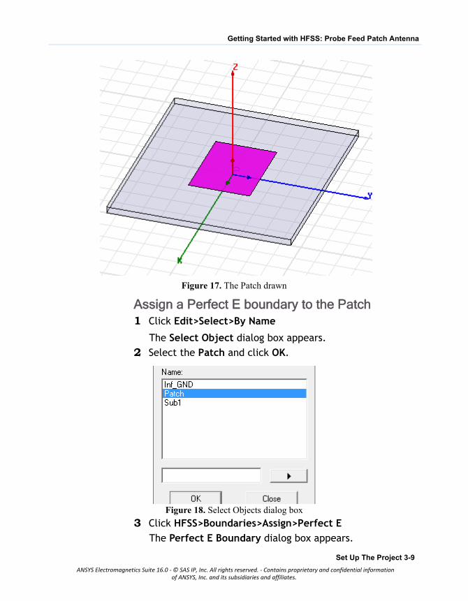
Figure 17. The Patch drawn
Assign a Perfect E boundary to the Patch1 Click Edit>Select>By Name
The Select Object dialog box appears.
2 Select the Patch and click OK.
Figure 18. Select Objects dialog box
3 Click HFSS>Boundaries>Assign>Perfect E
The Perfect E Boundary dialog box appears.
Set Up The Project 3-9
ANSYS Electromagnetics Suite 16.0 - © SAS IP, Inc. All rights reserved. - Contains proprietary and confidential informationof ANSYS, Inc. and its subsidiaries and affiliates.
Getting Started with HFSS: Probe Feed Patch Antenna
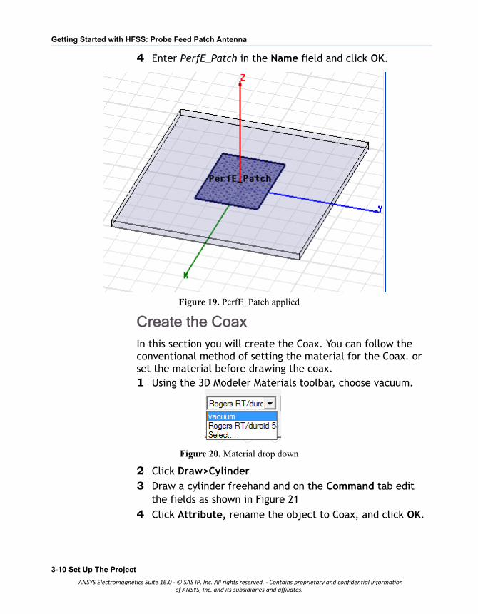
4 Enter PerfE_Patch in the Name field and click OK.
Figure 19. PerfE_Patch applied
Create the CoaxIn this section you will create the Coax. You can follow the conventional method of setting the material for the Coax. or set the material before drawing the coax.1 Using the 3D Modeler Materials toolbar, choose vacuum.
Figure 20. Material drop down
2 Click Draw>Cylinder
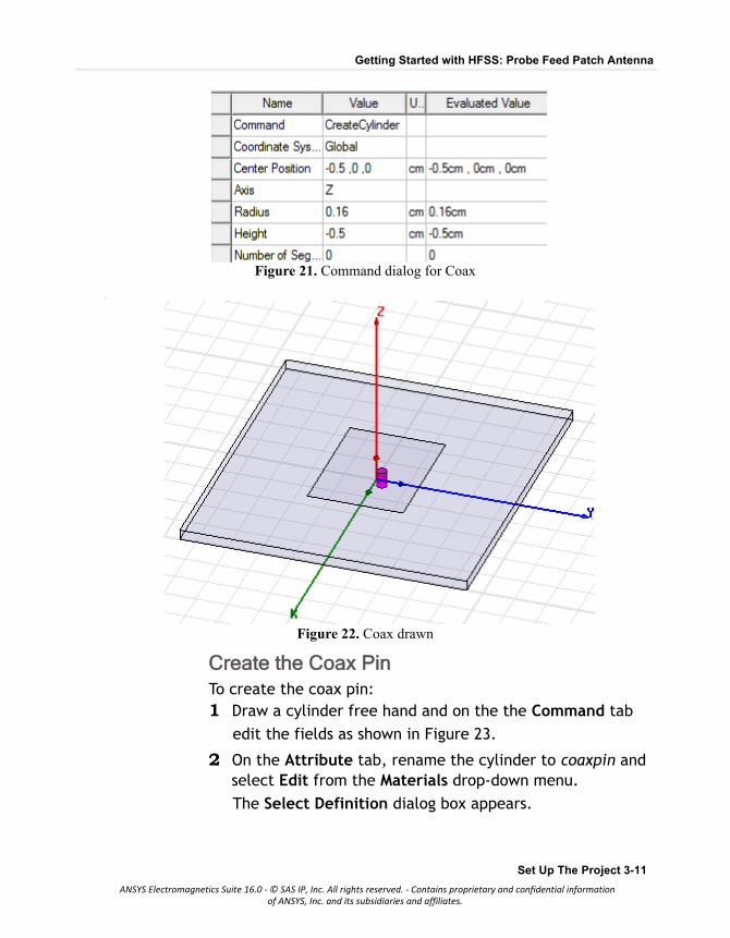
3 Draw a cylinder freehand and on the Command tab edit the fields as shown in Figure 21
4 Click Attribute, rename the object to Coax, and click OK.
3-10 Set Up The Project
ANSYS Electromagnetics Suite 16.0 - © SAS IP, Inc. All rights reserved. - Contains proprietary and confidential informationof ANSYS, Inc. and its subsidiaries and affiliates.
Getting Started with HFSS: Probe Feed Patch Antenna
Figure 21. Command dialog for Coax
.
Figure 22. Coax drawn
Create the Coax PinTo create the coax pin:1 Draw a cylinder free hand and on the the Command tab
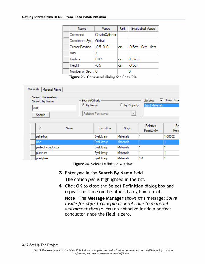
edit the fields as shown in Figure 23.
2 On the Attribute tab, rename the cylinder to coaxpin and select Edit from the Materials drop-down menu.
The Select Definition dialog box appears.
Set Up The Project 3-11
ANSYS Electromagnetics Suite 16.0 - © SAS IP, Inc. All rights reserved. - Contains proprietary and confidential informationof ANSYS, Inc. and its subsidiaries and affiliates.
Getting Started with HFSS: Probe Feed Patch Antenna
Figure 23. Command dialog for Coax Pin
Figure 24. Select Definition window
3 Enter pec in the Search By Name field.
The option pec is highlighted in the list.
4 Click OK to close the Select Definition dialog box and repeat the same on the other dialog box to exit.
Note The Message Manager shows this message: Solve inside for object coax pin is unset, due to material assignment change. You do not solve inside a perfect conductor since the field is zero.
3-12 Set Up The Project
ANSYS Electromagnetics Suite 16.0 - © SAS IP, Inc. All rights reserved. - Contains proprietary and confidential informationof ANSYS, Inc. and its subsidiaries and affiliates.
Getting Started with HFSS: Probe Feed Patch Antenna
.
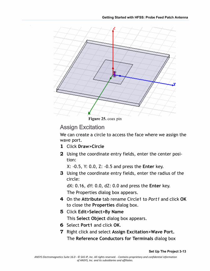
Figure 25. coax pin
Assign ExcitationWe can create a circle to access the face where we assign the wave port.1 Click Draw>Circle
2 Using the coordinate entry fields, enter the center posi-tion:
X: -0.5, Y: 0.0, Z: -0.5 and press the Enter key.
3 Using the coordinate entry fields, enter the radius of the circle:
dX: 0.16, dY: 0.0, dZ: 0.0 and press the Enter key.
The Properties dialog box appears.
4 On the Attribute tab rename Circle1 to Port1 and click OK to close the Properties dialog box.
5 Click Edit>Select>By Name
This Select Object dialog box appears.
6 Select Port1 and click OK.
7 Right click and select Assign Excitation>Wave Port.
The Reference Conductors for Terminals dialog box
Set Up The Project 3-13
ANSYS Electromagnetics Suite 16.0 - © SAS IP, Inc. All rights reserved. - Contains proprietary and confidential informationof ANSYS, Inc. and its subsidiaries and affiliates.
Getting Started with HFSS: Probe Feed Patch Antenna
appears..
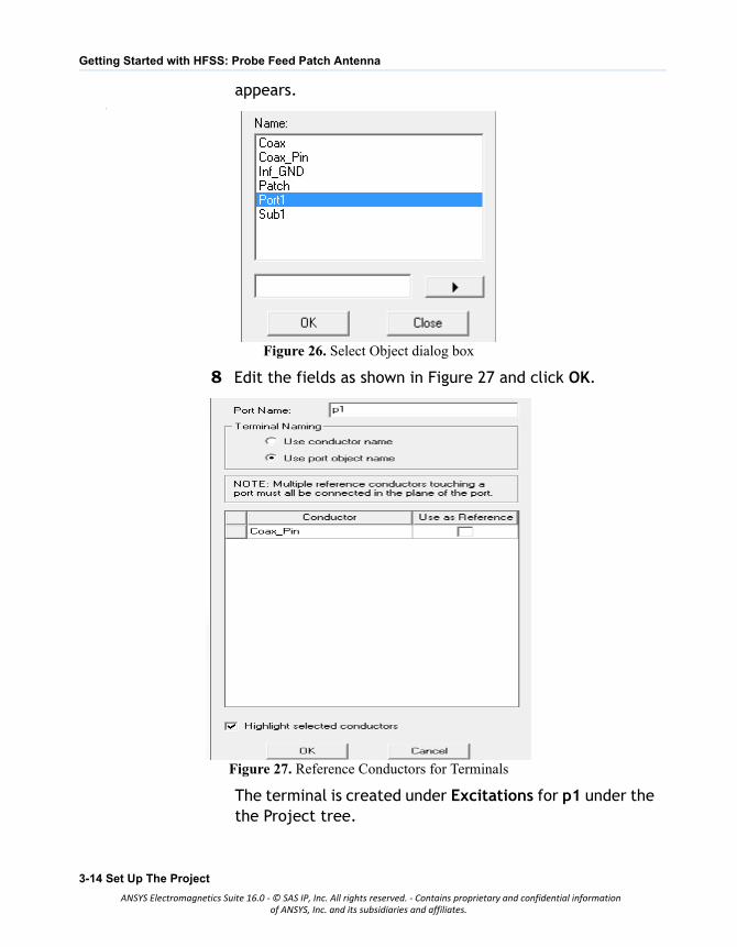
Figure 26. Select Object dialog box
8 Edit the fields as shown in Figure 27 and click OK.
Figure 27. Reference Conductors for Terminals
The terminal is created under Excitations for p1 under the the Project tree.
3-14 Set Up The Project
ANSYS Electromagnetics Suite 16.0 - © SAS IP, Inc. All rights reserved. - Contains proprietary and confidential informationof ANSYS, Inc. and its subsidiaries and affiliates.
Getting Started with HFSS: Probe Feed Patch Antenna
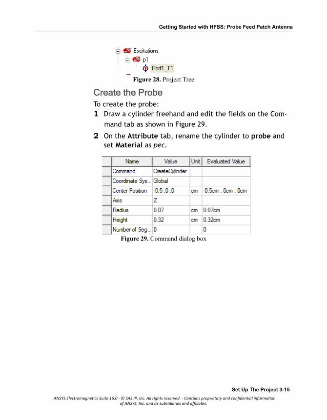
Figure 28. Project Tree
Create the ProbeTo create the probe:1 Draw a cylinder freehand and edit the fields on the Com-
mand tab as shown in Figure 29.
2 On the Attribute tab, rename the cylinder to probe and set Material as pec.
Figure 29. Command dialog box
Set Up The Project 3-15
ANSYS Electromagnetics Suite 16.0 - © SAS IP, Inc. All rights reserved. - Contains proprietary and confidential informationof ANSYS, Inc. and its subsidiaries and affiliates.
Getting Started with HFSS: Probe Feed Patch Antenna
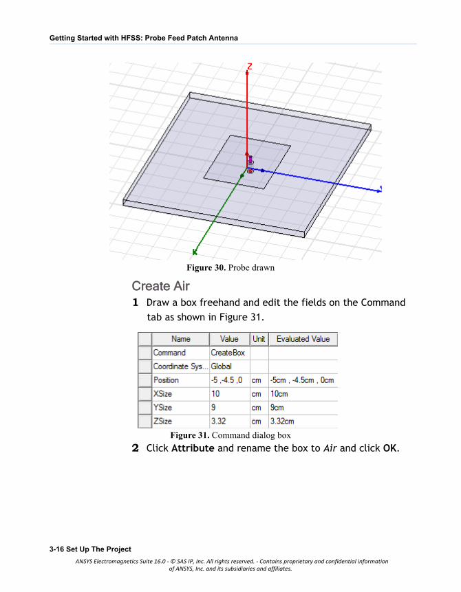
Figure 30. Probe drawn
Create Air1 Draw a box freehand and edit the fields on the Command
tab as shown in Figure 31.
Figure 31. Command dialog box
2 Click Attribute and rename the box to Air and click OK.
3-16 Set Up The Project
ANSYS Electromagnetics Suite 16.0 - © SAS IP, Inc. All rights reserved. - Contains proprietary and confidential informationof ANSYS, Inc. and its subsidiaries and affiliates.
Getting Started with HFSS: Probe Feed Patch Antenna
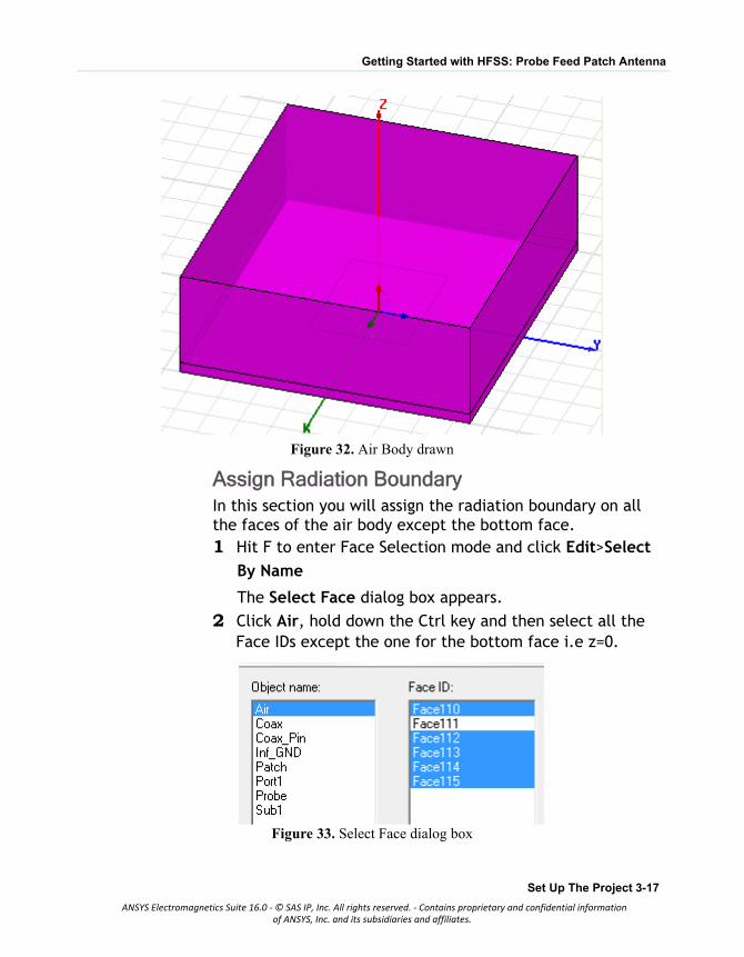
Figure 32. Air Body drawn
Assign Radiation BoundaryIn this section you will assign the radiation boundary on all the faces of the air body except the bottom face.1 Hit F to enter Face Selection mode and click Edit>Select
By Name
The Select Face dialog box appears.
2 Click Air, hold down the Ctrl key and then select all the Face IDs except the one for the bottom face i.e z=0.
Figure 33. Select Face dialog box
Set Up The Project 3-17
ANSYS Electromagnetics Suite 16.0 - © SAS IP, Inc. All rights reserved. - Contains proprietary and confidential informationof ANSYS, Inc. and its subsidiaries and affiliates.
Getting Started with HFSS: Probe Feed Patch Antenna
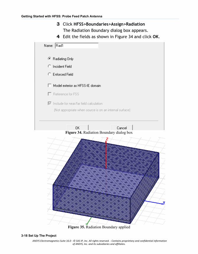
3 Click HFSS>Boundaries>Assign>Radiation
The Radiation Boundary dialog box appears.
4 Edit the fields as shown in Figure 34 and click OK.
Figure 34. Radiation Boundary dialog box
Figure 35. Radiation Boundary applied
3-18 Set Up The Project
ANSYS Electromagnetics Suite 16.0 - © SAS IP, Inc. All rights reserved. - Contains proprietary and confidential informationof ANSYS, Inc. and its subsidiaries and affiliates.
Getting Started with HFSS: Probe Feed Patch Antenna
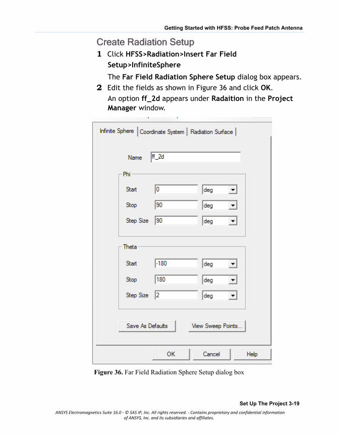
Create Radiation Setup1 Click HFSS>Radiation>Insert Far Field
Setup>InfiniteSphere
The Far Field Radiation Sphere Setup dialog box appears.
2 Edit the fields as shown in Figure 36 and click OK.
An option ff_2d appears under Radaition in the Project Manager window.
Figure 36. Far Field Radiation Sphere Setup dialog box
Set Up The Project 3-19
ANSYS Electromagnetics Suite 16.0 - © SAS IP, Inc. All rights reserved. - Contains proprietary and confidential informationof ANSYS, Inc. and its subsidiaries and affiliates.

4 Analyze the Model
This chapter contains the following topics: Add Solution Setup Add Frequency Sweep Model Validation Analyze All Review Solution Data Review the Profile Panel Review the Convergence Panel Review the Matrix Data Panel Review the Mesh Statistics Panel Create Reports Create Terminal Solution Data Report Create Far Field Overlays
Analyze the Model 4-1
ANSYS Electromagnetics Suite 16.0 - © SAS IP, Inc. All rights reserved. - Contains proprietary and confidential informationof ANSYS, Inc. and its subsidiaries and affiliates.
Getting Started with HFSS: Probe Feed Patch Antenna
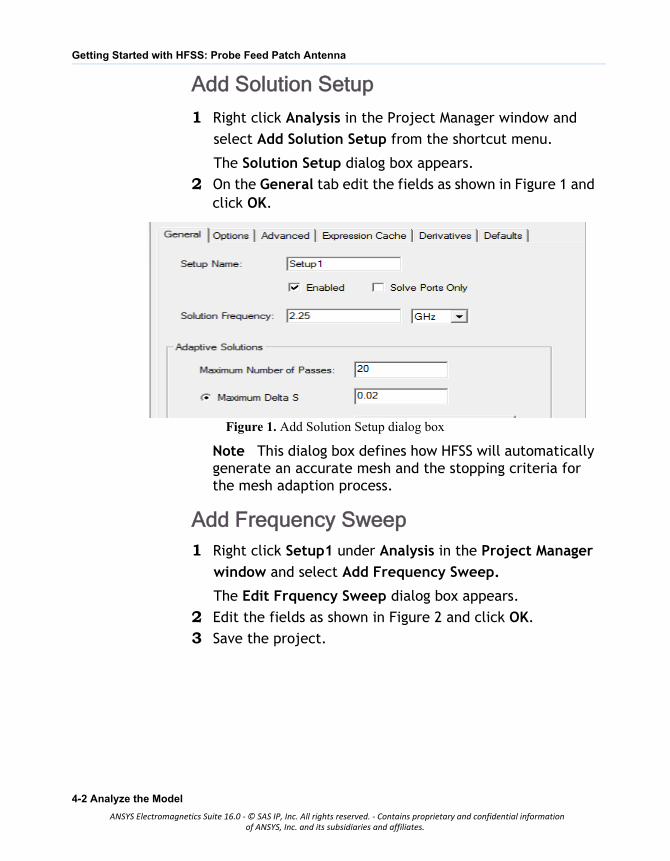
Add Solution Setup
1 Right click Analysis in the Project Manager window and
select Add Solution Setup from the shortcut menu.
The Solution Setup dialog box appears.
2 On the General tab edit the fields as shown in Figure 1 and click OK.
Figure 1. Add Solution Setup dialog box
Note This dialog box defines how HFSS will automatically generate an accurate mesh and the stopping criteria for the mesh adaption process.
Add Frequency Sweep1 Right click Setup1 under Analysis in the Project Manager
window and select Add Frequency Sweep.
The Edit Frquency Sweep dialog box appears.
2 Edit the fields as shown in Figure 2 and click OK.
3 Save the project.
4-2 Analyze the Model
ANSYS Electromagnetics Suite 16.0 - © SAS IP, Inc. All rights reserved. - Contains proprietary and confidential informationof ANSYS, Inc. and its subsidiaries and affiliates.
Getting Started with HFSS: Probe Feed Patch Antenna
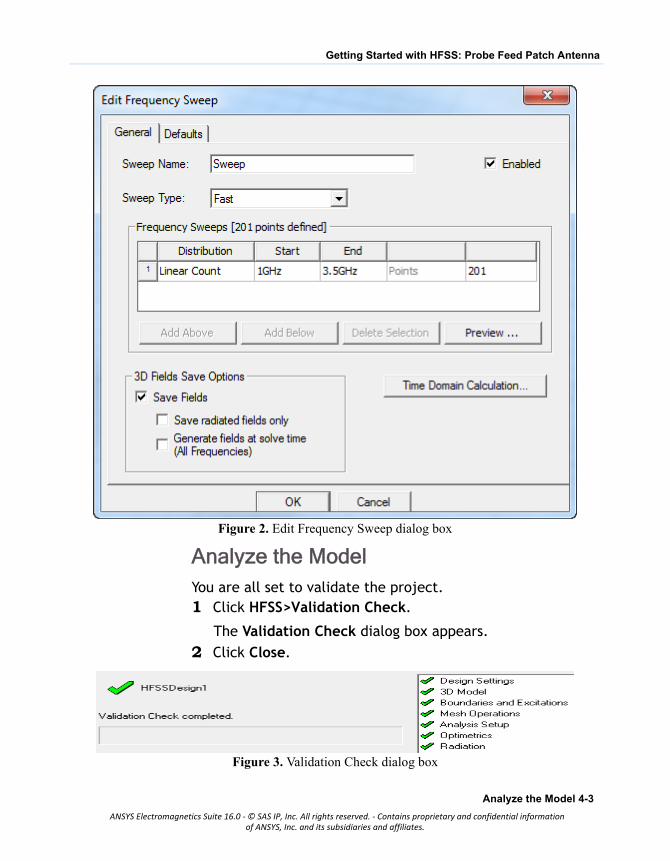
Figure 2. Edit Frequency Sweep dialog box
Analyze the ModelYou are all set to validate the project.1 Click HFSS>Validation Check.
The Validation Check dialog box appears.
2 Click Close.
Figure 3. Validation Check dialog box
Analyze the Model 4-3
ANSYS Electromagnetics Suite 16.0 - © SAS IP, Inc. All rights reserved. - Contains proprietary and confidential informationof ANSYS, Inc. and its subsidiaries and affiliates.
Getting Started with HFSS: Probe Feed Patch Antenna
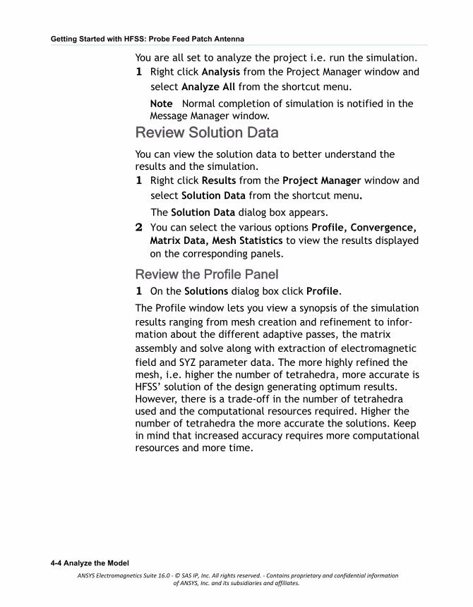
You are all set to analyze the project i.e. run the simulation.1 Right click Analysis from the Project Manager window and
select Analyze All from the shortcut menu.
Note Normal completion of simulation is notified in the Message Manager window.
Review Solution DataYou can view the solution data to better understand the results and the simulation.1 Right click Results from the Project Manager window and
select Solution Data from the shortcut menu.
The Solution Data dialog box appears.
2 You can select the various options Profile, Convergence, Matrix Data, Mesh Statistics to view the results displayed on the corresponding panels.
Review the Profile Panel1 On the Solutions dialog box click Profile.
The Profile window lets you view a synopsis of the simulationresults ranging from mesh creation and refinement to infor-mation about the different adaptive passes, the matrixassembly and solve along with extraction of electromagneticfield and SYZ parameter data. The more highly refined the mesh, i.e. higher the number of tetrahedra, more accurate is HFSS’ solution of the design generating optimum results. However, there is a trade-off in the number of tetrahedra used and the computational resources required. Higher the number of tetrahedra the more accurate the solutions. Keep in mind that increased accuracy requires more computational resources and more time.
4-4 Analyze the Model
ANSYS Electromagnetics Suite 16.0 - © SAS IP, Inc. All rights reserved. - Contains proprietary and confidential informationof ANSYS, Inc. and its subsidiaries and affiliates.
Getting Started with HFSS: Probe Feed Patch Antenna
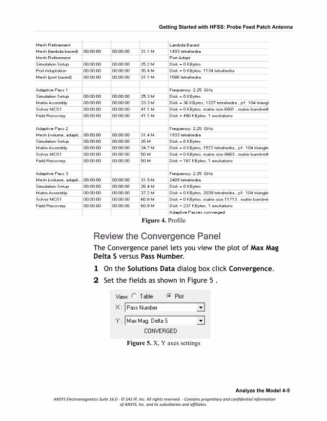
Figure 4. Profile
Review the Convergence PanelThe Convergence panel lets you view the plot of Max Mag Delta S versus Pass Number.
1 On the Solutions Data dialog box click Convergence.
2 Set the fields as shown in Figure 5 .
Figure 5. X, Y axes settings
Analyze the Model 4-5
ANSYS Electromagnetics Suite 16.0 - © SAS IP, Inc. All rights reserved. - Contains proprietary and confidential informationof ANSYS, Inc. and its subsidiaries and affiliates.
Getting Started with HFSS: Probe Feed Patch Antenna
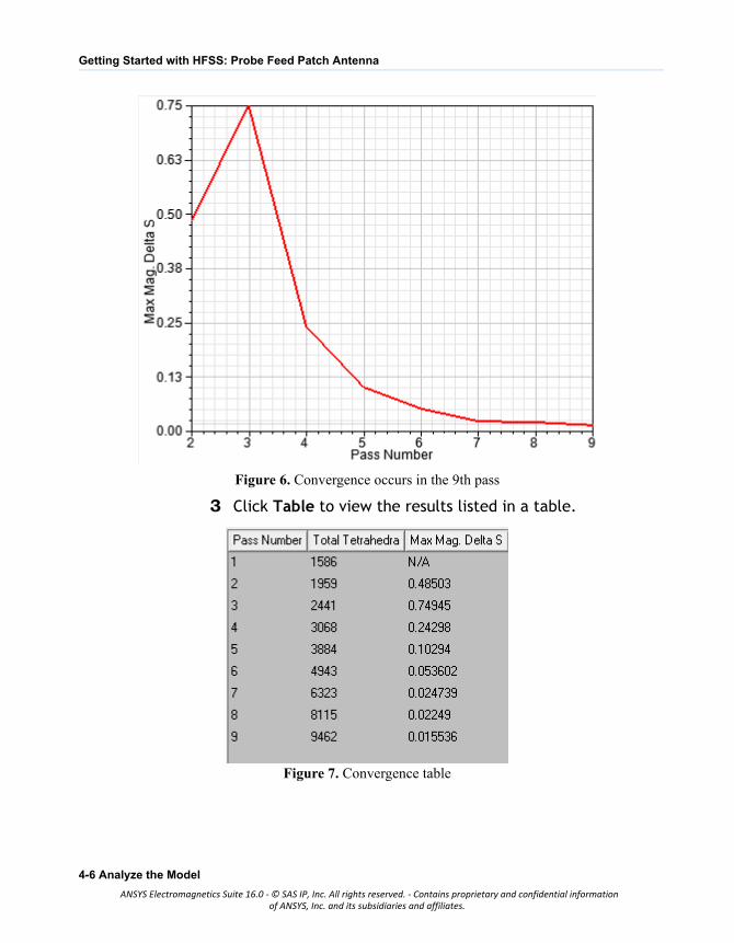
Figure 6. Convergence occurs in the 9th pass
3 Click Table to view the results listed in a table.
Figure 7. Convergence table
4-6 Analyze the Model
ANSYS Electromagnetics Suite 16.0 - © SAS IP, Inc. All rights reserved. - Contains proprietary and confidential informationof ANSYS, Inc. and its subsidiaries and affiliates.
Getting Started with HFSS: Probe Feed Patch Antenna
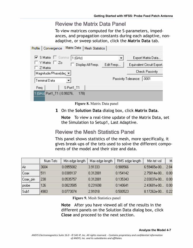
Review the Matrix Data PanelTo view matrices computed for the S-parameters, imped-ances, and propagation constants during each adaptive, non-adaptive, or sweep solution, click the Matrix Data tab.
Figure 8. Matrix Data panel
1 On the Solution Data dialog box, click Matrix Data.
Note To view a real-time update of the Matrix Data, set the Simulation to Setup1, Last Adaptive.
Review the Mesh Statistics PanelThis panel shows statistics of the mesh, more specifically, it gives break-ups of the tets used to solve the different compo-nents of the model and their size and data.
Figure 9. Mesh Statistics panel
Note After you have viewed all of the results in the different panels on the Solution Data dialog box, click Close and proceed to the next section.
Analyze the Model 4-7
ANSYS Electromagnetics Suite 16.0 - © SAS IP, Inc. All rights reserved. - Contains proprietary and confidential informationof ANSYS, Inc. and its subsidiaries and affiliates.

Getting Started with HFSS: Probe Feed Patch Antenna
Create ReportsThis section deals with report creation. HFSS offers the report dialog box where you can enter the desired settings and gen-erate reports.
Create Terminal Solution Data Report
1 Right click Results and select Create Terminal Solution
Data Report>Rectangular Plot.
The Report dialog box window appears.
2 Ensure that the fields are as shown in Figure 45.
Figure 10. Report dialog box
3 Click New Report. and then, Close.
4-8 Analyze the Model
ANSYS Electromagnetics Suite 16.0 - © SAS IP, Inc. All rights reserved. - Contains proprietary and confidential informationof ANSYS, Inc. and its subsidiaries and affiliates.
Getting Started with HFSS: Probe Feed Patch Antenna
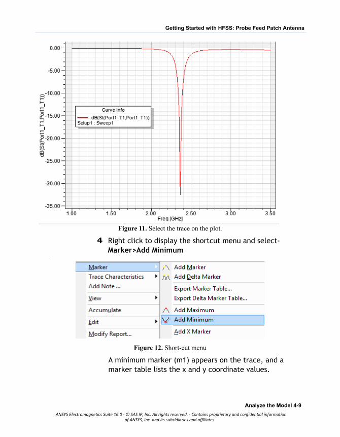
Figure 11. Select the trace on the plot.
4 Right click to display the shortcut menu and select-Marker>Add Minimum
.
Figure 12. Short-cut menu
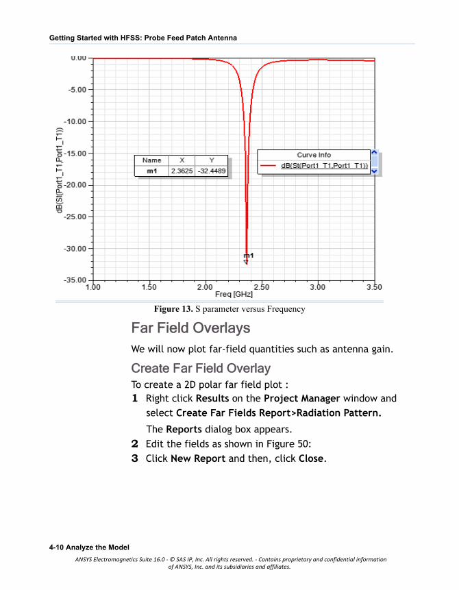
A minimum marker (m1) appears on the trace, and a marker table lists the x and y coordinate values.
Analyze the Model 4-9
ANSYS Electromagnetics Suite 16.0 - © SAS IP, Inc. All rights reserved. - Contains proprietary and confidential informationof ANSYS, Inc. and its subsidiaries and affiliates.
Getting Started with HFSS: Probe Feed Patch Antenna
Figure 13. S parameter versus Frequency
Far Field OverlaysWe will now plot far-field quantities such as antenna gain.
Create Far Field OverlayTo create a 2D polar far field plot :1 Right click Results on the Project Manager window and
select Create Far Fields Report>Radiation Pattern.
The Reports dialog box appears.
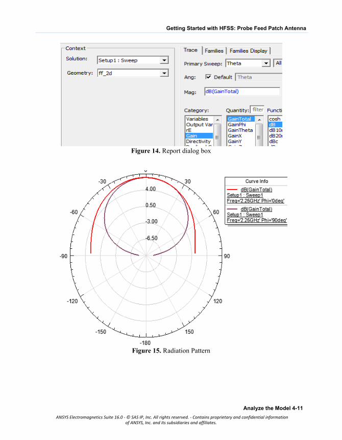
2 Edit the fields as shown in Figure 50:
3 Click New Report and then, click Close.
4-10 Analyze the Model
ANSYS Electromagnetics Suite 16.0 - © SAS IP, Inc. All rights reserved. - Contains proprietary and confidential informationof ANSYS, Inc. and its subsidiaries and affiliates.
Getting Started with HFSS: Probe Feed Patch Antenna
Figure 14. Report dialog box
Figure 15. Radiation Pattern
Analyze the Model 4-11
ANSYS Electromagnetics Suite 16.0 - © SAS IP, Inc. All rights reserved. - Contains proprietary and confidential informationof ANSYS, Inc. and its subsidiaries and affiliates.