Embed Size (px)
DESCRIPTION
Getting Started with EPICS Lecture Series. The EPICS Motor Record. Ronald L. Sluiter 03/01/05. Overview. Acknowledgements. Supported device list. Feature list. Coordinate systems. Configuration example. Feedback. Retries. Backlash Correction. Distribution. - PowerPoint PPT Presentation
Citation preview

A U.S. Department of EnergyOffice of Science LaboratoryOperated by The University of Chicago
Argonne National Laboratory
Office of ScienceU.S. Department of Energy
Getting Started with EPICS Lecture Series
The EPICS Motor Record
Ronald L. Sluiter03/01/05

Pioneering Science andTechnology
Office of Science U.S. Department
of Energy
Overview
Acknowledgements.
Supported device list.
Feature list.
Coordinate systems.
Configuration example.
Feedback.
Retries.
Backlash Correction.
Distribution.
Note: All of following refers to R5-5 of the motor distribution.
Pioneering Science andTechnology
Office of Science U.S. Department
of Energy
Acknowledgments
Jim Kowalkowski - original author. Tim Mooney and Joe Sullivan. Myself, since 1998. Mark Rivers
motor interface to Hideos, MPF and ASYN. Newport, Mclennan and ACS device drivers.
Kevin Peterson – MicroMo MVP 2001 B02 device driver. Kurt Goetze –Micos MoCo dc device driver. Users who report bugs and help fix them.

Pioneering Science andTechnology
Office of Science U.S. Department
of Energy
Supported device list
1. Oregon Micro Systems, Inc. models; VME8, VME44, VME58, VS4, VX2 and MAXv.
2. Highland Technologies model V540.
3. Newport models MM3000, MM4000, MM4005, MM4006, PM500, ESP300 and XPSC8.
4. Soft Channel.
5. Advanced Control Systems, Corp. model MCB-4B.
6. Mclennan models PM304 and PM600.
7. Intelligent Motion Systems, Inc. (IMS) models IM483 and MDrive.
8. MX device driver.
9. Physik Instrumente (PI) GmbH & Co. model C-844.
10. MicroMo model MVP 2001 B02.
11. Micos model MoCo dc controller.
12. Delta Tau PMAC2-VME controller.
Pioneering Science andTechnology
Office of Science U.S. Department
of Energy
Feature list
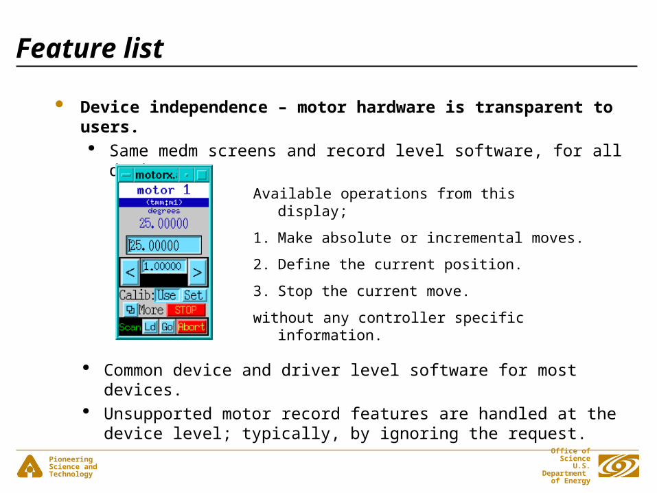
Device independence – motor hardware is transparent to users. Same medm screens and record level software, for all devices.
Common device and driver level software for most devices. Unsupported motor record features are handled at the device level;
typically, by ignoring the request.
Available operations from this display;
1. Make absolute or incremental moves.
2. Define the current position.
3. Stop the current move.
without any controller specific information.
Pioneering Science andTechnology
Office of Science U.S. Department
of Energy
Cont'd Feature list
The scope of the motor record is limited to single axis, non-coordinated, point to point moves.
Absolute, relative and incremental moves. Supports stepper, DC and Soft Channel motors. Very few fields
are motor type specific; PID parameters (PCOF/ICOF/DCOF) for DC motors. Velocity base (VBAS) for stepper motors. Done Moving Input Link (DINP) for Soft Channel.
Three different position coordinate systems; user, dial and raw. Record level backlash correction. Homing.
Pioneering Science andTechnology
Office of Science U.S. Department
of Energy
Cont'd Feature list
Software travel limits. Send motor controller command primitives at initialization, pre-
move and post-move; (INIT, PREM, POST). Drive Power Monitoring and Motor Synchronized DB Puts via
Device Directives. Jogging. Motor record closed-loop control via Retries. Position feedback from either a EPICS PV link or a motor
controller. Define current position (SET). Continuous, periodic updates via the Status Update field (STUP).

Pioneering Science andTechnology
Office of Science U.S. Department
of Energy
Terminology
Stepper motors step and encoders tick. Readback <=> Feedback target position - a user requested, static, absolute position (VAL). commanded position – the motor controller’s current, dynamic,
absolute reference position (RMP).

Pioneering Science andTechnology
Office of Science U.S. Department
of Energy
Coordinate systems.
Typically, raw coordinates are the units that software uses to communicate to the motor controller. Position commands to a ... stepper motor controller are in steps. DC motor controller are in encoder ticks.
Exception – some controllers communicate in engineering units (EGU’s); e.g., inch, mm, degrees.
Motor resolution field (MRES) converts raw values to dial values. Convert raw target position (RVAL) to dial target (DVAL):
DVAL [EGU’s] = RVAL [steps] * MRES [EGU’s/step] User units are based on dial units, the User Direction field (DIR)
and the User Offset field (OFF) Convert dial target position (DVAL) to user target (VAL):
VAL = (DVAL * DIR) + OFF; where DIR = +/- 1.

Pioneering Science andTechnology
Office of Science U.S. Department
of Energy
Cont'd Coordinate systems.
X
RVAL
MRES
DIR
OFF
X
DVAL
VAL
+
Raw
Dial
User
EGU’s
steps/ticks

Pioneering Science andTechnology
Office of Science U.S. Department
of Energy
Configuration example
Set the engineering units field (EGU); inch, mm, degrees . Set the motor resolution (MRES) field which is in units of …
(EGU’s / motor step) for stepper motors. (EGU’s / encoder tick) for DC motors.
Pioneering Science andTechnology
Office of Science U.S. Department
of Energy
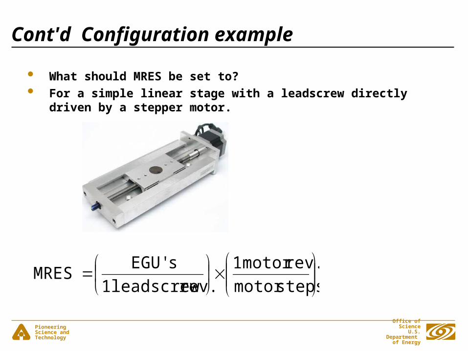
Cont'd Configuration example
What should MRES be set to? For a simple linear stage with a leadscrew directly driven by a
stepper motor.
stepsmotor
rev.motor 1
rev. leadscrew 1
sEGU'MRES

Pioneering Science andTechnology
Office of Science U.S. Department
of Energy
Cont'd Configuration example
UREV = EGU’s / 1 leadscrew rev. SREV = motor steps / 1 motor rev. > 0 MRES = UREV / SREV MRES and UREV allow negative values so that the record’s
coordinate system can be configured to the opposite polarity of the motor controller's.
Never change MRES while the motor is moving.
Pioneering Science andTechnology
Office of Science U.S. Department
of Energy
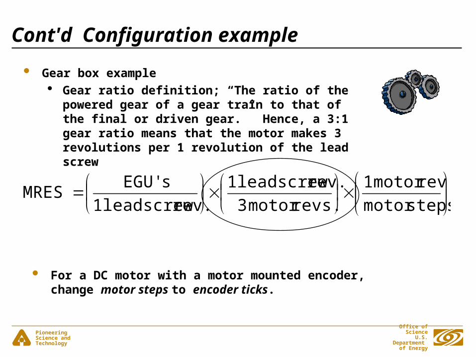
Cont'd Configuration example
Gear box example Gear ratio definition; “The ratio of the powered gear
of a gear train to that of the final or driven gear.” Hence, a 3:1 gear ratio means that the motor makes 3 revolutions per 1 revolution of the lead screw
stepsmotor
revmotor 1
revs.motor 3
rev. leadscrew 1
rev. leadscrew 1
sEGU'MRES
For a DC motor with a motor mounted encoder, change motor steps to encoder ticks.

Pioneering Science andTechnology
Office of Science U.S. Department
of Energy
Feedback Two ways to input position feedback to the motor record:
1. From driver support, via the motor controller.
2. From an EPICS PV, via a stand-alone, feedback device, For feedback from driver support:
Driver level code sets the Encoder is Present bit (EA_PRESENT) in the Motor Status field (MSTA) to True at initialization.
The Raw Encoder Position field (REP) has the motor controllers’ raw encoder value [ticks].
Configuring feedback from driver support: Set the Encoder Resolution field (ERES) to convert encoder
ticks to EGU’s. The Use Encoder If Present field (UEIP) determines if the REP
is used [Yes/No].

Pioneering Science andTechnology
Office of Science U.S. Department
of Energy
Cont'd Feedback
Configuring feedback from an EPICS PV: Set Readback PV link (RDBL). Set the Readback Resolution (RRES) to convert the RDBL PV
units to EGU’s. The Use Readback If Present field (URIP) determines if the
RDBL PV link is used [Yes/No]. Raw Motor Position (RMP) is the current commanded position
read from the motor controller. If motor record closed-loop control is off (UEIP & URIP both set to No), then RVAL = RMP after every move.
Raw Readback Value field (RRBV) can be in units of either steps or ticks.
Pioneering Science andTechnology
Office of Science U.S. Department
of Energy
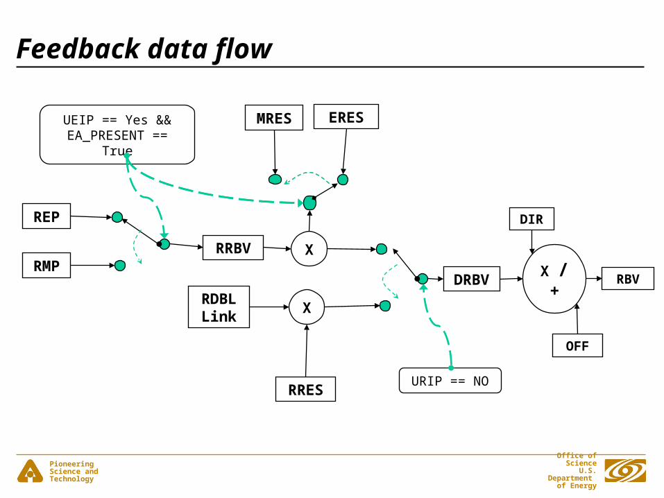
Feedback data flow
X / +
RBV
OFF
DIRREP
RMPXRRBV
ERES
RDBL Link
X
RRES
DRBV
MRESUEIP == Yes &&
EA_PRESENT == True
URIP == NO

Pioneering Science andTechnology
Office of Science U.S. Department
of Energy
REP
RMP
RRBV
RRES
RDBL
STUP
RVAL
UEIP
URIP

Pioneering Science andTechnology
Office of Science U.S. Department
of Energy
Retries
What it isn’t. Retries are not continuous, dynamic loop closure. What it is. Retries try to eliminate dial position error (DIFF) by
making, consecutive, relative moves based on the DIFF field. DIFF = DVAL – DRBV If ((EA_PRESENT = True, AND, UEIP == Yes), OR, URIP == Yes) is
True, then all motor record moves are relative moves. Note that when the above is true, retries change the commanded
position, not the target position. RVAL != RMP after a retry. Configuring retries:
Never set UEIP == Yes for a DC motor. Set Retry Deadband (RDBD); retry if (DIFF > RDBD); RDBD
limited to >= MRES. Set Max Retry Count (RTRY) - maximum number of retries. Current Retry Count (RCNT) – clear at beginning of every move.

Pioneering Science andTechnology
Office of Science U.S. Department
of Energy
Backlash Correction
Backlash - lost motion due to mechanical imperfections.
• Backlash configuration: Backlash distance (BDST) determines both the magnitude and
direction of the backlash move. The backlash has its’ own velocity (BVEL) and acceleration
(BACC) parameters. Backlash correction algorithm:
Preferred direction - the sign of BDST. Slew parameters - slew velocity (VELO) and acceleration
(ACCL). Backlash parameters - BVEL and BACC.
Pioneering Science andTechnology
Office of Science U.S. Department
of Energy
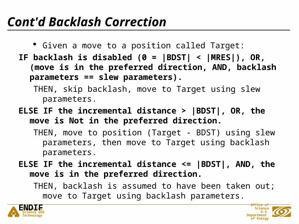
Cont'd Backlash Correction
Given a move to a position called Target:
IF backlash is disabled (0 = |BDST| < |MRES|), OR, (move is in the preferred direction, AND, backlash parameters == slew parameters).
THEN, skip backlash, move to Target using slew parameters.
ELSE IF the incremental distance > |BDST|, OR, the move is Not in the preferred direction.
THEN, move to position (Target - BDST) using slew parameters, then move to Target using backlash parameters.
ELSE IF the incremental distance <= |BDST|, AND, the move is in the preferred direction.
THEN, backlash is assumed to have been taken out; move to Target using backlash parameters.
ENDIF

Pioneering Science andTechnology
Office of Science U.S. Department
of Energy
The motor distribution
Motor distribution web location.
http://www.aps.anl.gov/upd/people/sluiter/epics/motor/index.html What is in the tar file?
Motor record database definition. Motor record level support library. Device/driver libraries for various controllers. Motor record/device/driver level documentation. Motor record release documentation. Two example applications; one with ASYN and one without
ASYN. README files for some devices that contain configuration
document.
Pioneering Science andTechnology
Office of Science U.S. Department
of Energy
Cont'd motor distribution
Motor System generation. <motor>/configure/RELEASE:
Only EPICS_BASE is required. ASYN is required for serial or GPIB based devices drivers.
<motor>/motorApp/Makefile: Define which device/driver modules to build.


![Skaffold - storage.googleapis.com · [getting-started getting-started] Hello world! [getting-started getting-started] Hello world! [getting-started getting-started] Hello world! 5](https://img.pdfslide.us/doc/110x75/5ec939f2a76a033f091c5ac7/skaffold-getting-started-getting-started-hello-world-getting-started-getting-started.jpg)