Embed Size (px)
Citation preview
Calhoun: The NPS Institutional Archive
Theses and Dissertations Thesis Collection
2013-06
Getting MANETs to communicate efficiently: an
analysis of mobile Ad Hoc network routing schemes
in tactical communications
Colbert, Garry M.
Monterey, California: Naval Postgraduate School
http://hdl.handle.net/10945/34646
NAVAL
POSTGRADUATE
SCHOOL
MONTEREY, CALIFORNIA
THESIS
Approved for public release; distribution is unlimited
GETTING MANETS TO COMMUNICATE EFFICIENTLY: AN ANALYSIS OF MOBILE AD HOC
NETWORK ROUTING SCHEMES IN TACTICAL COMMUNICATIONS
by
Garry M. Colbert
June 2013
Thesis Advisor: Alex Bordetsky Second Reader: John Looney

THIS PAGE INTENTIONALLY LEFT BLANK
i
REPORT DOCUMENTATION PAGE Form Approved OMB No. 0704-0188 Public reporting burden for this collection of information is estimated to average 1 hour per response, including the time for reviewing instruction,
searching existing data sources, gathering and maintaining the data needed, and completing and reviewing the collection of information. Send
comments regarding this burden estimate or any other aspect of this collection of information, including suggestions for reducing this burden, to Washington headquarters Services, Directorate for Information Operations and Reports, 1215 Jefferson Davis Highway, Suite 1204, Arlington, VA
22202-4302, and to the Office of Management and Budget, Paperwork Reduction Project (0704-0188) Washington DC 20503.
1. AGENCY USE ONLY (Leave blank)
2. REPORT DATE June 2013
3. REPORT TYPE AND DATES COVERED Master’s Thesis
4. TITLE AND SUBTITLE
GETTING MANETS TO COMMUNICATE EFFICIENTLY: AN ANALYSIS OF
MOBILE AD HOC NETWORK ROUTING SCHEMES IN TACTICAL
COMMUNICATIONS
5. FUNDING NUMBERS
6. AUTHOR(S) Garry M. Colbert
7. PERFORMING ORGANIZATION NAME(S) AND ADDRESS(ES)
Naval Postgraduate School
Monterey, CA 93943-5000
8. PERFORMING ORGANIZATION
REPORT NUMBER
9. SPONSORING /MONITORING AGENCY NAME(S) AND ADDRESS(ES)
N/A 10. SPONSORING/MONITORING
AGENCY REPORT NUMBER
11. SUPPLEMENTARY NOTES The views expressed in this thesis are those of the author and do not reflect the official policy
or position of the Department of Defense or the U.S. government. IRB Protocol number ____N/A____.
12a. DISTRIBUTION / AVAILABILITY STATEMENT Approved for public release; distribution is unlimited
12b. DISTRIBUTION CODE A
13. ABSTRACT (maximum 200 words)
Warfighting based on Commander’s Intent and Mission Tactics will remain the foundation of command and control,
but the information structure that supports Marine Corps tactical units will continuously undergo changes based on
developments in information technology.
Mobile Ad Hoc Networking is one of the information technology developments that the Marine Corps is currently
studying. Mobile Ad Hoc Network’s (MANETs) are infrastructureless, highly mobile communications and their
multi-hop routing capabilities have the potential to reliably and robustly extend existing networks to the tactical edge.
There are many challenges to MANET implementation however, including management of the dynamic physical
topology, and the efficient use of limited spectral and energy resources. One platform being tested by the Marine
Corps utilizes a time-division multiple access (TDMA) scheme combined with Barrage Relaying to ensure robust
communications. Other schemes for MANETs employ intelligent-routing protocols. This thesis examines those
protocols and identifies the parameters needed to implement a tactical MANET routing scheme. The findings of this
research advance understanding of MANETs and the elements necessary to enable their use in support of tactical
communications; bringing the Marine Corps closer to its goal of lightweight and efficient tactical communications.
14. SUBJECT TERMS Mobile Ad Hoc Networks, MANETs, Ad Hoc Routing Protocols,
TrellisWare, Energy Efficiency, Tactical Communications 15. NUMBER OF
PAGES 81
16. PRICE CODE
17. SECURITY
CLASSIFICATION OF
REPORT Unclassified
18. SECURITY
CLASSIFICATION OF THIS
PAGE
Unclassified
19. SECURITY
CLASSIFICATION OF
ABSTRACT
Unclassified
20. LIMITATION OF
ABSTRACT
UU
NSN 7540-01-280-5500 Standard Form 298 (Rev. 2-89)
Prescribed by ANSI Std. 239-18

ii
THIS PAGE INTENTIONALLY LEFT BLANK
iii
Approved for public release; distribution is unlimited
GETTING MANETS TO COMMUNICATE EFFICIENTLY: AN ANALYSIS OF
MOBILE AD HOC NETWORK ROUTING SCHEMES IN TACTICAL
COMMUNICATIONS
Garry M. Colbert
Major, United States Marine Corps
B.S., United States Naval Academy, 2001
Submitted in partial fulfillment of the
requirements for the degree of
MASTER OF SCIENCE IN SYSTEMS TECHNOLOGY
(COMMAND, CONTROL & COMMUNICATIONS
from the
NAVAL POSTGRADUATE SCHOOL
June 2013
Author: Garry M. Colbert
Approved by: Alex Bordetsky, PhD
Thesis Advisor
John Looney, PhD
Second Reader
Dan Boger, PhD
Chair, Department of Information Sciences

iv
THIS PAGE INTENTIONALLY LEFT BLANK
v
ABSTRACT
Warfighting based on Commander’s Intent and Mission Tactics will remain the
foundation of command and control, but the information structure that supports Marine
Corps tactical units will continuously undergo changes based on developments in
information technology.
Mobile Ad Hoc Networking is one of the information technology developments
that the Marine Corps is currently studying. Mobile Ad Hoc Network’s (MANETs) are
infrastructureless, highly mobile communications and their multi-hop routing capabilities
have the potential to reliably and robustly extend existing networks to the tactical edge.
There are many challenges to MANET implementation however, including
management of the dynamic physical topology, and the efficient use of limited spectral
and energy resources. One platform being tested by the Marine Corps utilizes a time-
division multiple access (TDMA) scheme combined with Barrage Relaying to ensure
robust communications. Other schemes for MANETs employ intelligent-routing
protocols. This thesis examines those protocols and identifies the parameters needed to
implement a tactical MANET routing scheme. The findings of this research advance
understanding of MANETs and the elements necessary to enable their use in support of
tactical communications; bringing the Marine Corps closer to its goal of lightweight and
efficient tactical communications.

vi
THIS PAGE INTENTIONALLY LEFT BLANK
vii
TABLE OF CONTENTS
I. INTRODUCTION........................................................................................................1
II. BACKGROUND AND LITERATURE REVIEW ...................................................5 A. BACKGROUND ..............................................................................................5
1. Routing ..................................................................................................5 2. Mobile Ad Hoc Networks ....................................................................6 3. Ad Hoc Routing Protocols ...................................................................8
a. Proactive Protocols ...................................................................8 b. Reactive Protocols ...................................................................11 c. Hybrid Protocols .....................................................................13
4. Decision Support Systems .................................................................14 B. LITERATURE REVIEW .............................................................................16
1. Kioumourtzis: Simulation and Evaluation of Routing Protocols for Mobile Ad Hoc Networks ............................................................16
2. Bordetsky and Hayes-Roth: Extending the OSI Model for Wireless Battlefield Networks: a Design Approach to The 8th Layer For Tactical Hypernodes ........................................................17
3. Gateau: Extending Simple Network Management Protocol Beyond Network Management: A MIB Architecture for Network-Centric Services .................................................................18
4. Gruber: Integration and Management of Emerging Tactical Mesh Networks Combined with Unattended Sensor Networks, Ultra-Wideband Links, and Ad-Hoc Mobile Tactical Radios. ......19
5. Puff: Network Management System for Tactical Mobile Ad-Hoc Network Segments......................................................................20
6. Rivera: Distributed Agent Based Networks in Support of Advanced Marine Corps Command and Control Concept ...........20
III. RESEARCH METHODOLOGY .............................................................................23 A. THE TRELLISWARE CHEETAHNET II TW-230 RADIO ....................23
1. Mobile Ad-Hoc Network Mission Configuration Tool ...................26 2. Tactical Topology Viewer Controller...............................................28
B. RESEARCH DESIGN ...................................................................................30
IV. EXPERIMENTATION AND RESULTS ................................................................37 A. ENHANCED MAGTF OPERATIONS LIMITED OBJECTIVE
EXPERIMENT 3 ...........................................................................................37 1. Concept of Employment ....................................................................38 2. LOE 3 Results and Data Analysis.....................................................39
B. NPS EXPERIMENTATION .........................................................................42 1. Concept of the Experiment ...............................................................42 2. Urban Patrol Results and Data Analysis .........................................46 3. Battery Testing Results......................................................................48
viii
V. CONCLUSIONS AND RECOMMENDATIONS FOR FURTHER RESEARCH ...............................................................................................................53 A. CONCLUSIONS ............................................................................................53 B. RECOMMENDATIONS ...............................................................................56
APPENDIX A: “COLBERT.JAVA” ...................................................................................57
SUPPLEMENTAL: DATA COLLECTED FROM MARINE CORPS WARFIGHTING LAB EXERCISE AND NPS EXPERIMENTS ........................59
LIST OF REFERENCES ......................................................................................................61
INITIAL DISTRIBUTION LIST .........................................................................................63
ix
LIST OF FIGURES
Figure 1. The network splits due to the severing of the link nodes 1 and 5 ......................7 Figure 2. Multipoint Relays (From Belding-Royer, 2004). ............................................10 Figure 3. DSR Route Request and Route Response (From Belding-Royer, 2004).........13 Figure 4. ZRP 2-Hop Zone with Periphery Nodes Shown (From Belding-Royer,
2004) ................................................................................................................14 Figure 5. Rule Based Reasoning Model components and interactions (From Lewis,
1999). ...............................................................................................................15 Figure 6. CBR Model components and interactions (From Subramanian, 2010) ...........16 Figure 7. TrellisWare Web Application Screen (From TrellisWare Technologies,
2012b) ..............................................................................................................26 Figure 8. Device Settings Tab of MMC (From TrellisWare Technologies, Inc.,
2012b) ..............................................................................................................27 Figure 9. TTVC Node List and Remote Media Stream Windows ..................................29 Figure 10. TrellisWare Link List Window (From TrellisWare Technologies, 2012a) .....29 Figure 11. Link Cost for Ad-Hoc Routing Scheme...........................................................31 Figure 12. HEAT Map Interface (From Bourakov, 2012) ................................................31 Figure 13. Link Cost Equation that takes into account threshold SNR. ............................32 Figure 14. TrellisWare Asynchronous Node, Link and Event Content available (From
TrellisWare Technologies, 2011) .....................................................................33 Figure 15. EMO LOE 3 Scheme of Maneuver (From Marine Corps Warfighting Lab,
2013) ................................................................................................................39 Figure 16. Sample of Unparsed Data from LOE 3 Experiment ........................................40 Figure 17. Sample of Refined Data Showing Link Quality and Link Color .....................40 Figure 18. Link Quality vs. Link Color Value Plotted using MATLAB ..........................42 Figure 19. Stationary Locations: CENETIX Laboratory, Relay Nodes 1, 2, and 3.
(created using mapsengine.google.com) ..........................................................44 Figure 20. Foot Patrol Route (created using mapsengine.google.com) ............................44 Figure 21. Vehicle Patrol Route (created using mapsengine.google.com) .......................45 Figure 22. Garmin Forerunner 10 Speed vs. Time Graph for Foot Patrol (from
connect.garmin.com)........................................................................................47 Figure 23. Garmin Forerunner 10 Speed vs. Time Graph for Vehicle Patrol (from
connect.garmin.com)........................................................................................47 Figure 24. Last known Position and Contact with Vehicle Patrol unit .............................48 Figure 25. Formula for Percent Deviation.........................................................................49 Figure 26. Battery Test Results In Microsoft Excel ..........................................................50

x
THIS PAGE INTENTIONALLY LEFT BLANK

xi
LIST OF TABLES
Table 1. TrellisWare CheetahNet II TW-230 Technical Specifications (From TrellisWare Technologies, 2012c) ...................................................................24
Table 2. CBR case structure based on mobility and node density factors. ....................34 Table 3. Radio Initialization settings for experiment .....................................................43

xii
THIS PAGE INTENTIONALLY LEFT BLANK
xiii
LIST OF ACRONYMS AND ABBREVIATIONS
AMPR Aerial Mobile Ad Hoc Network Passive Relay AODV Ad Hoc On Demand Distance Vector API Application Programming Interface ATH At The Halt BLT Battalion Landing Team C2 Command and Control CBR Case Based Reasoning CENETIX Center for Network Innovation and Experimentation CLT Company Landing Team CMC Commandant of the Marine Corps COMSEC Communications Security DB Decibel DNA Dynamic Network Architecture DoD Department of Defense DOTMLPF Doctrine, Organization, Training, Materiel, Leadership, Personnel,
and Facilities DSDV Destination Sequenced Distance Vector DSR Dynamic Source Routing EFSS Expeditionary Fire Support System ECO Enhanced Company Operations EMO Enhanced Marine Air Ground Task Force Operations FSCC Fire Support Coordination Center GPS Global Positioning System HIMARS High Mobility Artillery Rocket System IP Internet Protocol JSON JavaScript Object Notation Kbps Kilobits Per Second LOE Limited Objective Experiment MAGTF Marine Air Ground Task Force MANET Mobile Ad Hoc Network Mbps Megabits Per Second
xiv
MGRS Military Grid Reference System MHz Megahertz MIB Management Information Base MIO Maritime Interdiction Operations MMC Mobile Ad Hoc Network Mission Configuration MPH Miles Per Hour MPR Multipoint Relay NAT Network Address Translation NIC Network Interface Card NMS Network Management System NOC Network Operations Center NCW Network Centric Warfare OSI Open Systems Interconnection OSLR Optimized Link State Routing OTH Over The Horizon OTM On The Move PHY Physical Layer QoS Quality of Service RF Radio Frequency RREP Route Reply RREQ Route Request SACC Supporting Arms Coordination Center SNMP Simple Network Management Protocol SNR Signal-to-Noise Ratio TBRPF Topology Based Reverse Path Forwarding TC Topological Control TDMA Time Division Multiple Access TMN Telecommunications Network Management Model TTPs Tactics, Techniques, and Procedures TTV-C Tactical Topology View-Controller UTM Universal Transverse Mercator UWB Ultra-Wideband ZRP Zone Routing Protocol

xv
ACKNOWLEDGMENTS
All praises are to God, the one and only God, whose son, Jesus Christ, died for
our sins and on the third day was resurrected, so that whosoever believeth in him shall
not perish, but will have eternal life. Thank God for his everlasting Grace and Mercy,
who does not deal with us according to our iniquities. Praise the Lord, with all my heart,
my soul, and my strength! My faith has been increased as a result of my time here.
Angelic, without you I am incomplete. Our union has been blessed by God, and I
become more aware of that fact with each day that passes. You have blessed me with a
beautiful child, and you love me unconditionally. I know for a fact that I would not have
made it this far without you. I will always love you, best friend.
Morgan, Christina, daddy loves you very much. You mean the world to me.
I can’t write a paragraph for everybody, but here’s a list:
Mike Lavery: (Thanks for letting me tag along) Josh Kapp: (My third thesis advisor) Ted Huffmire: (Changed my life in 30 minutes). Shoreline Young Married Couples Group: (Answered Prayer Streak continues!)

xvi
THIS PAGE INTENTIONALLY LEFT BLANK
1
I. INTRODUCTION
History often defines eras by its predominant technological advancement. The
Bronze Age, the Iron Age, and the Industrial Age are just a few examples of eras
associated with technology. Mobile devices are pervasive today, and computing devices
are increasingly transitioning from the desktop system to smaller, lightweight and more
portable laptops and tablet computers. Alberts, Garstka, and Stein (1999) observed that
the dominant technology of the present day is information technology; therefore, this era
is labeled the Information Age. The Marine Corps wants to use the tools of the
Information Age to enhance warfighting capabilities in a revolutionary way. Mobile Ad-
Hoc Networking (MANET) is an emerging technology whose potential presents an
opportunity to greatly improve warfighting capabilities. The Marine Corps understands
the need to maintain a competitive advantage in this age and the continuing requirement
to adapt its Doctrine, Organization, Training, Materiel, Leadership Education, Personnel
and Facilities (DOTMLPF) to defeat any adversary.
In previous ages, warfare adapted to dominant technologies (Van Creveld, 1985).
The Information Age is no different, and Albert’s et al. (1999) heralded this with their
concept called Network Centric Warfare (NCW), where all elements of the warfighting
apparatus are highly connected by electronic information networks down to the
individual person or unattended sensor (Alberts, Garstka, & Stein, 1999). Network
Centric Warfare is
An information-superiority enabled concept of operations that generates increased combat power by networking sensors, decision makers, and shooters to achieve shared awareness, increased speed of command, higher tempo of operations, greater lethality, increased survivability, and a degree of self-synchronization. (Alberts et al., 1999)
The goal of NCW is to increase combat effectiveness through the increased
awareness and knowledge throughout an organization, enabling through faster decision
cycles (Alberts, Garstka, & Stein, 1999). In essence, the network and its infrastructure
becomes a key enabler that promotes increased tempo and self-synchronization of
operations.
2
The acquisition of information and knowledge is very important, but collecting
information must neither decrease the tempo of operations nor foster indecisiveness.
The fundamental nature of warfare is a forceful struggle between opposing entities, and
the “enemy always gets a vote.” Decisiveness is paramount to Marine Corps’ Command
and Control (C2) processes and execution because it puts the enemy in a reactionary
mode, where the enemy’s actions/reactions are dictated by the Marine Leader. Mission
Command maximizes combat effectiveness by ensuring decisive action despite
uncertainty and time constraints (United States Marine Corps, 1996).
Mission Command is predicated on a commander assigning missions to
subordinates and communicating his or her intent. Commander’s Intent articulates the
commander’s vision of success on the battlefield; it represents the desired end-state. The
commander executes mission tactics by assigning a mission (or task) to subordinates with
constraints, but does not define how the subordinate is to execute the mission. This in
turn fosters the creativity of the subordinate in the planning and execution of the assigned
mission. Furthermore, should the overall situation change, the subordinate is allowed to
adapt plans and operations as long as they are in line with the commander’s intent.
Mission Command will always be the backbone of Marine Corps leadership in
warfare, but tactics, techniques and procedures (TTPs) that the warfighter use constantly
adapt to the enemy and the environment. While he was the Commandant of the Marine
Corps, General Conway set the path for how the Marine Corps would conduct warfare in
the 21st Century in Marine Corps Vision and Strategy 2025 (2008). Although it
preceded the Marine Corps strategy document, FORCEnet (Clark & Hagee, 2005) is the
functional concept that supports that future vision and strategy. FORCEnet applies the
concept of NCW in the Information Age to the Marine Corps C2 doctrine. The objective
of FORCEnet is not to eliminate uncertainty; instead FORCEnet seeks to enhance the
commander’s decision-making process and the effective execution of his intent across the
force (Clark & Hagee, 2005). FORCEnet describes the concept of a ubiquitous network
that increases the quality, quantity and timeliness of information products and services
available to the warfighter.

3
The goal of FORCEnet is to connect the greatest number of sensors, units,
weapons, commanders and staffs as possible because when such a state exists, all the
benefits of decentralization (e.g., initiative, adaptability, and increased tempo) can be
realized while simultaneously realizing the benefits associated with a centralized C2
architecture—i.e., coordination and unity of effort (Clark & Hagee, 2005). Admiral
Clark and General Hagee established a 2015-2020 deadline for FORCEnet, and they
delineated the core capabilities needed to achieve it. The core capabilities, when realized,
shall enable a robust, reliable, and interoperable C2 structure that (1) conveys accurate
friendly and known enemy position location information, (2) automates minor decisions,
and (3) efficiently presents relevant information to the commander.
MANET is one technology that is capable of contributing to the accomplishment
of those goals. Mobile Ad Hoc Networking is beneficial in many applications where an
underlying communications infrastructure is not present, or the establishment of one is
not advantageous (Basagni, Conti, Giordano, & Stojmenovic, 2004). MANETs are
rapidly deployable, scalable, and capable of connecting nodes that are beyond line of
sight (Basagni, Conti, Giordano, & Stojmenovic, 2004). MANETs also extend existing
infrastructure-based networks (e.g. Wide Area Networks) to the tactical edge, which
manifests the vision of the network effect.
There are many challenges in the design and implementation of MANETs. One
of the unique challenges to MANETs is network management. Due to the dynamic
physical topology and decentralized architecture, fault detection and performance
monitoring is difficult (Basagni, Conti, Giordano, & Stojmenovic, 2004). In addition,
MANETs are constrained by bandwidth and energy limitations due to their high mobility.
(Basagni, Conti, Giordano, & Stojmenovic, 2004). To mitigate these challenges, a
resource efficient autonomous network management system must be employed. A
potential solution would involve the hypernode concept (Bordetsky & Hayes-Roth,
2007). Hypernodes operating above the application layer (the eighth Layer) could use
case based reasoning to make network management decisions based on environmental
factors. Multiple MANET transmission and routing schemes have been developed, and
researchers continue to tackle the many challenges associated with MANET routing.
4
There are two main categories of information routing techniques used in current
MANET systems: the barrage relay scheme, and the intelligent routing scheme. The
barrage relay scheme employs every node other than the source and destination node as a
relay. The intelligent routing scheme determines the best path between the source and
destination before sending a message. The problem identified and analyzed by this thesis
is the determination of an effective routing metric for use in intelligent routing---a key
component of MANET operation. In examining this problem, the following research
questions emerge: (1) What are the relevant factors in establishing the cost of each link
for a given route between a source and destination, (2) Can those factors be measured, (3)
How can a case-based reasoning (CBR) approach be applied to maximize the
effectiveness of an intelligently routed MANET (4) What are some key factors needed in
a CBR case, and (5) Can that information be captured using the system’s current network
management platform?
The platform used in conducting this research is the TrellisWare CheetahNet II
TW-230 radio system. The CheetahNet II TW-230 is a man-portable MANET platform
that operates under low power. The CheetahNet radio systems are currently being
evaluated by the Marine Corps Warfighting Lab for their ability to extend infrastructure
based networks to units on the move (OTM) and at the halt (ATH).
A potential benefit to this study is that it could advance the Marine Corps towards
its goal of robust, reliable tactical communications as envisioned in FORCEnet. This
thesis identifies key variables necessary for a useful case and the optimal means to collect
the values of those variables. Recommendations on intelligent routing approaches for
MANETs are also addressed.
The thesis is organized into the following chapters. Chapter II presents the
background principles associated with Mobile Ad Hoc Networks, and it provides a
summary of recent research on MANETs. Chapter III dictates the method of conducting
research for the thesis, and it outlines relevant metrics to be captured during field
experiments. Chapter IV presents and analyzes the data collected during the experiments.
Chapter V summarizes the thesis, presents the conclusions, and makes recommendations
for future research.
5
II. BACKGROUND AND LITERATURE REVIEW
This chapter represents a summary of the literature that led to the determination of
gaps in the ability of MANETs to support the information exchange capabilities of
tactical team at the edge of the battlespace to achieve the capabilities envisioned in the
Marine Corps Vision and Strategy 2025 (2008). In addition, the background and
literature review from whence this chapter came also aided in the design of the
experiments used to answer the research questions posed in Chapter 1.
A. BACKGROUND
1. Routing
Routing is the process of directing data in a network (Dean, 2013). Routing is
conducted either statically or dynamically. In static routing, an administrator directs the
path of information from a source to a destination in or among networks (Dean, 2013). In
dynamic routing, a connectivity device determines the best route between a source and
destination. Dynamic routing generally occurs at Layer 3 of the OSI model (Dean,
2013).
Routers are connectivity devices that perform routing (Dean, 2013). Although
routers can be configured to process static routes, it is not the optimal configuration due
to the continuously changing state of networks (Dean, 2013). There are three types of
routers: interior, exterior, and gateway routers (Dean, 2013). Interior routers direct traffic
among nodes in a network; exterior routers direct data between networks; and gateway
routers connect interior routers to exterior routers (Dean, 2013). Routers rely on routing
tables, which store routes for destinations and destination networks.
Routers direct data based on routing protocols. Routing protocols determine the
best path to a destination. The best path is considered the most efficient path between the
source and destination (Dean, 2013). Routing protocols determine the best path based on
a routing metric (Dean, 2013), which is a way assigning a value to a specific path.
Routing metrics are assigned to a path based on many factors, including the number of
hops between to the destination, the throughput of a path, the delay along a path, and the
6
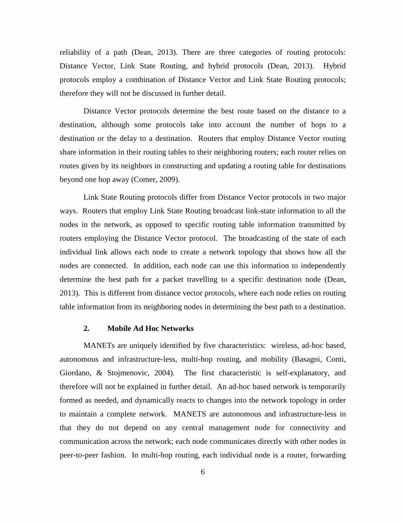
reliability of a path (Dean, 2013). There are three categories of routing protocols:
Distance Vector, Link State Routing, and hybrid protocols (Dean, 2013). Hybrid
protocols employ a combination of Distance Vector and Link State Routing protocols;
therefore they will not be discussed in further detail.
Distance Vector protocols determine the best route based on the distance to a
destination, although some protocols take into account the number of hops to a
destination or the delay to a destination. Routers that employ Distance Vector routing
share information in their routing tables to their neighboring routers; each router relies on
routes given by its neighbors in constructing and updating a routing table for destinations
beyond one hop away (Comer, 2009).
Link State Routing protocols differ from Distance Vector protocols in two major
ways. Routers that employ Link State Routing broadcast link-state information to all the
nodes in the network, as opposed to specific routing table information transmitted by
routers employing the Distance Vector protocol. The broadcasting of the state of each
individual link allows each node to create a network topology that shows how all the
nodes are connected. In addition, each node can use this information to independently
determine the best path for a packet travelling to a specific destination node (Dean,
2013). This is different from distance vector protocols, where each node relies on routing
table information from its neighboring nodes in determining the best path to a destination.
2. Mobile Ad Hoc Networks
MANETs are uniquely identified by five characteristics: wireless, ad-hoc based,
autonomous and infrastructure-less, multi-hop routing, and mobility (Basagni, Conti,
Giordano, & Stojmenovic, 2004). The first characteristic is self-explanatory, and
therefore will not be explained in further detail. An ad-hoc based network is temporarily
formed as needed, and dynamically reacts to changes into the network topology in order
to maintain a complete network. MANETS are autonomous and infrastructure-less in
that they do not depend on any central management node for connectivity and
communication across the network; each node communicates directly with other nodes in
peer-to-peer fashion. In multi-hop routing, each individual node is a router, forwarding
7
the packets it receives. The individual nodes are mobile, and the topology of the nodes is
constantly changing due to node mobility.
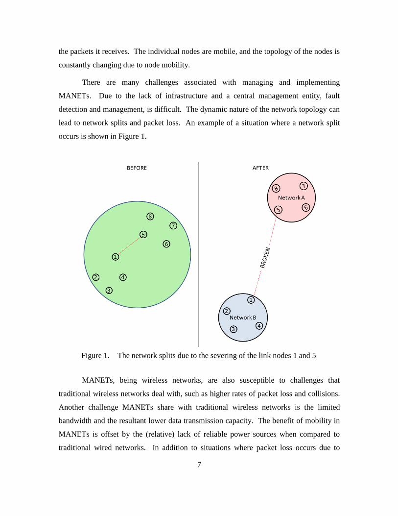
There are many challenges associated with managing and implementing
MANETs. Due to the lack of infrastructure and a central management entity, fault
detection and management, is difficult. The dynamic nature of the network topology can
lead to network splits and packet loss. An example of a situation where a network split
occurs is shown in Figure 1.
Figure 1. The network splits due to the severing of the link nodes 1 and 5
MANETs, being wireless networks, are also susceptible to challenges that
traditional wireless networks deal with, such as higher rates of packet loss and collisions.
Another challenge MANETs share with traditional wireless networks is the limited
bandwidth and the resultant lower data transmission capacity. The benefit of mobility in
MANETs is offset by the (relative) lack of reliable power sources when compared to
traditional wired networks. In addition to situations where packet loss occurs due to
8
broken connections in the network, packet loss may also occur due to because overloaded
nodes. Overloaded nodes may drop packets when its received packets queue is full; if the
network management system does not manage this situation, sending or receiving nodes
will have no knowledge of the packet loss. The broadcasting of information always
presents a security challenge in wireless networks, and MANETs are no different in this
respect. Lastly, it is difficult to provide quality of service (QoS) guarantees when the
topology and reliability of the network nodes are dynamic.
3. Ad Hoc Routing Protocols
Belding-Royer (2004) explains that most, if not all, routing protocols for
MANETs have common assumptions and design goals. MANET routing protocols
operate under the following assumptions: all nodes have equal resources and capabilities
(e.g., range), bidirectional communications occur, networks consist of approximately 10–
100 nodes, and battery power is the greatest operating constraint. MANET routing
protocols therefore generally have the following design goals: (1) minimization of
necessary control and processing overhead to maximize bandwith and power resources
available to the user for information transmission, (2) use of multihop routing techniques
to transmit messages from the source to destination node when the two are outside the
source’s maximum transmission range, (3) management of the dynamic topology of the
networks in order to maintain a constant source-destination path for every node pair in
the network, and (4) the prevention of message loops which tie up necessary bandwidth.
The different protocols can be categorized as either proactive, reactive, or hybrids.
a. Proactive Protocols
Proactive protocols are derived from traditional distance vector and link
state protocols, where each node always maintains an up to date route to every other node
in the network. Route creation and maintenance occurs periodically or after an event is
triggered (e.g., when a link is added or removed). A key difference in proactive protocols
as opposed to traditional routing protocols is the rate of updates. Updates occur at
different rates based on the speed of nodes. The advantage of proactive protocols is that
a route is immediately available when needed. The instant route availability comes with
9
a significant control overhead cost in large networks or rapidly moving nodes.
Destination Sequenced Distance Vector routing (DSDV) and Optimized Link State
Routing (OSLR) are two proactive protocols studied extensively in MANET research
(Belding-Royer, 2004).
DSDV is a distance vector routing protocol that uses sequence numbers to
maintain the most up to date routes. Like all distance vector protocols, DSDV nodes are
only aware of their nearest neighbors; each node must rely on routing information from
its nearest neighbors. Each node has a routing table that contains the destination (Internet
protocol) IP, destination sequence number, next hop IP address, hop count, and the install
time. The sequence number identifies the most recent determined route to a destination
in the case that multiple routes exist; a higher sequence number represents a newer route.
The install time is used to identify when the route will expire (stale) (Perkins & Bhagwat,
1994). Routing table update messages are sent to other nodes, containing the destination
IP, destination sequence number, and hop count. There are two types of routing table
updates: full and incremental (Perkins & Bhagwat, 1994). Full updates send a node’s full
routing table, and incremental updates send only those routes that have changed since the
last update. Full updates are sent sparingly; incremental updates are sent more frequently
because there is less overhead associated with them. If a node receives two next hop
paths to a destination, the node chooses the path with the largest destination sequence
number (an indicator of the most updated route). If two paths have the same destination
sequence number, then the node chooses path with lowest hop count.
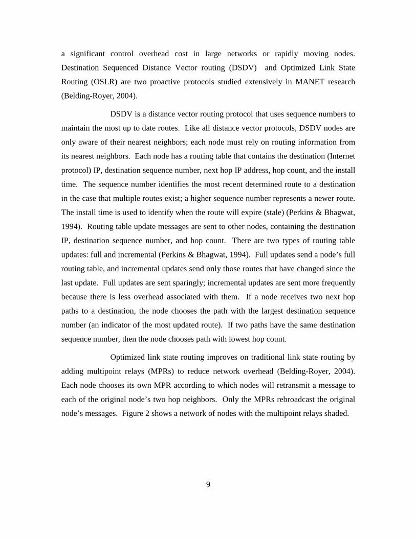
Optimized link state routing improves on traditional link state routing by
adding multipoint relays (MPRs) to reduce network overhead (Belding-Royer, 2004).
Each node chooses its own MPR according to which nodes will retransmit a message to
each of the original node’s two hop neighbors. Only the MPRs rebroadcast the original
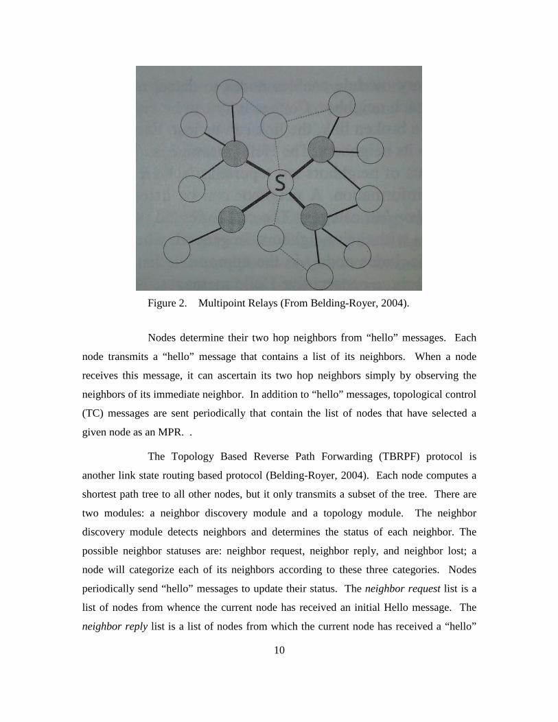
node’s messages. Figure 2 shows a network of nodes with the multipoint relays shaded.
10
Figure 2. Multipoint Relays (From Belding-Royer, 2004).
Nodes determine their two hop neighbors from “hello” messages. Each
node transmits a “hello” message that contains a list of its neighbors. When a node
receives this message, it can ascertain its two hop neighbors simply by observing the
neighbors of its immediate neighbor. In addition to “hello” messages, topological control
(TC) messages are sent periodically that contain the list of nodes that have selected a
given node as an MPR. .
The Topology Based Reverse Path Forwarding (TBRPF) protocol is
another link state routing based protocol (Belding-Royer, 2004). Each node computes a
shortest path tree to all other nodes, but it only transmits a subset of the tree. There are
two modules: a neighbor discovery module and a topology module. The neighbor
discovery module detects neighbors and determines the status of each neighbor. The
possible neighbor statuses are: neighbor request, neighbor reply, and neighbor lost; a
node will categorize each of its neighbors according to these three categories. Nodes
periodically send “hello” messages to update their status. The neighbor request list is a
list of nodes from whence the current node has received an initial Hello message. The
neighbor reply list is a list of nodes from which the current node has received a “hello”
11
message from after it has sent out a “hello” message to those nodes. The neighbor lost
list contains a list of nodes from which a node has not received a reply hello message
from. Routing occurs by computing the shortest path source tree using a variant of
Dijkstra’s algorithm (Belding-Royer, 2004). Only the Reportable Subtree (RT) is
transmitted.
b. Reactive Protocols
Reactive Routing Protocols differ from proactive protocols: each node
discovers routes only when needed; if a route does not already exist in the routing table or
the current route has expired, the source node will initiate the route discovery process.
The advantage of reactive routing protocols is that signaling overhead is lower than that
of proactive protocols, especially in moderate traffic conditions (Belding-Royer, 2004).
The disadvantage is the increased delay associated with route determination when
sending a message. The Ad-Hoc On Demand Distance Vector (AODV) protocol and the
Dynamic Source Routing (DSR) protocol are examples of reactive protocols.
Like the proactive routing protocols, AODV uses sequence numbers to
ensure the most recent path is chosen for routing to a destination. When a source node
needs to send a packet to a destination, it first checks its routing table to see if it has an
expired route. If the route exists, then the packet is forwarded using the route from the
table; if no route or an expired route exists, then the source node initiates the route
discovery process by issuing a Route Request (RREQ) packet, which contains the source
address, the destination address, the last known sequence number of the destination, the
hop count, and a new sequence number assigned to the route request (Belding-Royer,
2004). An intermediate node receives the RREQ and checks to see if it has a route to the
destination in its routing table. If it does, then it compares the destination sequence
number it has to the destination sequence number included in the RREQ packet for
staleness. A stale route is one that has a lower destination sequence number than the one
included in the route request packet. If the intermediate node has a stale route, then it
increments the hop count and forwards the request on. If it has the most recent hop
count, then it sends a route reply (RREP) message back to the sender with the known
12
route to the destination. If the source receives more than one RREP, it chooses the route
with the greatest sequence number, then the smallest hop count. In the case that a link
goes down, each node will send a route error (RERR) packet to all nodes in its routing
table that used that link to get to a particular destination. Each node forwards the packet
upstream to any other nodes that used the link.
Dynamic Source Routing is similar to AODV with a couple of notable
differences. DSR is a source routing protocol where data packets contain the full route to
the destination and the next hop is not determined at each intermediate hop (Belding-
Royer, 2004). During the route request process, each intermediate node that does not
have a route to the destination appends its own address to the original RREQ and then
forwards the message. When a node that does have a route to the destination receives the
route request packet, it appends the known route from its routing cache to the route
travelled by the route request packet, creating a full route from source to destination
(Belding-Royer, 2004). The intermediate node sends this full route back to the source in
a RREP message. DSR has a route cache instead of a route table, which contains
multiple routes to the destination. DSR nodes can exercise promiscuous listening.
Promiscuous listening occurs when a node receives a packet not addressed to it, retaining
the routing information stored in the packet for its own routing cache (Belding-Royer,
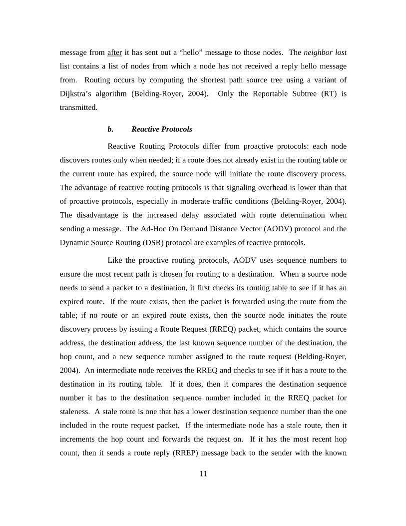
2004). An example of the DSR RREQ / RREP process is demonstrated in Figure 3
(Belding-Royer, 2004). In the example, the source node, marked “S”, sends a route
request, attempting to find a viable route to the destination, marked “D”. The RREQ
message arrives at the destination because none of the intermediate nodes has a viable
route in their caches. The destination node upon receiving the request sends the routing
information already in the RREQ message back to the source in a RREP message.
13
Figure 3. DSR Route Request and Route Response (From Belding-Royer, 2004).
c. Hybrid Protocols
Hybrid Protocols exhibit a combination of proactive and reactive protocol
characteristics based on specific circumstances. An example of a hybrid protocol is the
Zone Routing Protocol (ZRP). In the Zone Routing Protocol, a zone is established based
on a predetermined number of hops extending out from each node. A ZRP node executes
a proactive routing protocol within its zone. Routes to all destinations within the zone are
continuously known and updated. A ZRP node uses the Intrazone Routing protocol for
maintaining routes within the specified zone. The Intrazone Routing protocol is a link
state routing protocol. ZRP uses an Interzone Routing protocol for destination nodes that
are outside of the predefined zone. The Interzone Routing Protocol is reactive protocol
that establishes routes only when necessary. When a source node wishes to send a
message to a node that is outside its zone, the route discovery process begins. To execute
the Interzone Routing Protocol, ZRP uses peripheral nodes. For a given node, the
peripheral nodes are those nodes that are at the maximum number of hops away from the
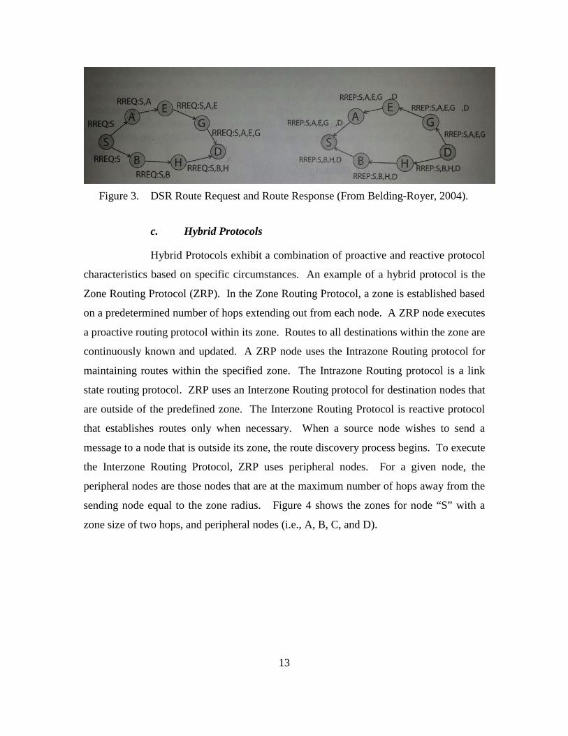
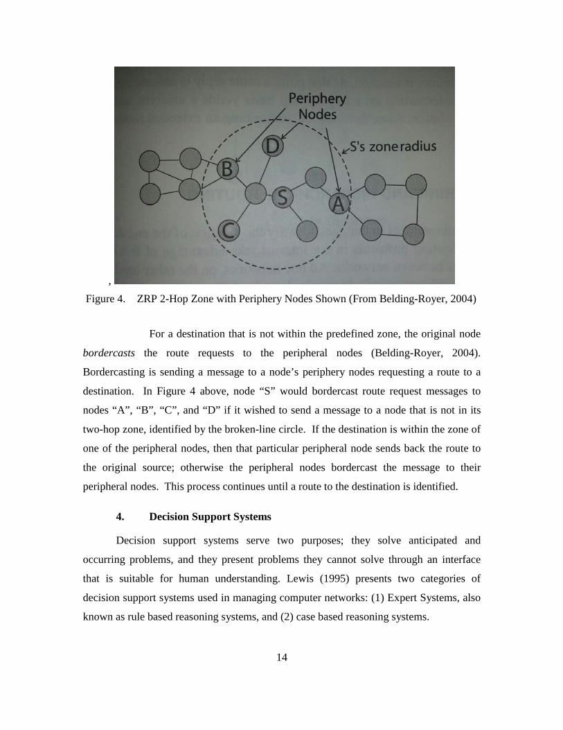
sending node equal to the zone radius. Figure 4 shows the zones for node “S” with a
zone size of two hops, and peripheral nodes (i.e., A, B, C, and D).
14
, Figure 4. ZRP 2-Hop Zone with Periphery Nodes Shown (From Belding-Royer, 2004)
For a destination that is not within the predefined zone, the original node
bordercasts the route requests to the peripheral nodes (Belding-Royer, 2004).
Bordercasting is sending a message to a node’s periphery nodes requesting a route to a
destination. In Figure 4 above, node “S” would bordercast route request messages to
nodes “A”, “B”, “C”, and “D” if it wished to send a message to a node that is not in its
two-hop zone, identified by the broken-line circle. If the destination is within the zone of
one of the peripheral nodes, then that particular peripheral node sends back the route to
the original source; otherwise the peripheral nodes bordercast the message to their
peripheral nodes. This process continues until a route to the destination is identified.
4. Decision Support Systems
Decision support systems serve two purposes; they solve anticipated and
occurring problems, and they present problems they cannot solve through an interface
that is suitable for human understanding. Lewis (1995) presents two categories of
decision support systems used in managing computer networks: (1) Expert Systems, also
known as rule based reasoning systems, and (2) case based reasoning systems.
15
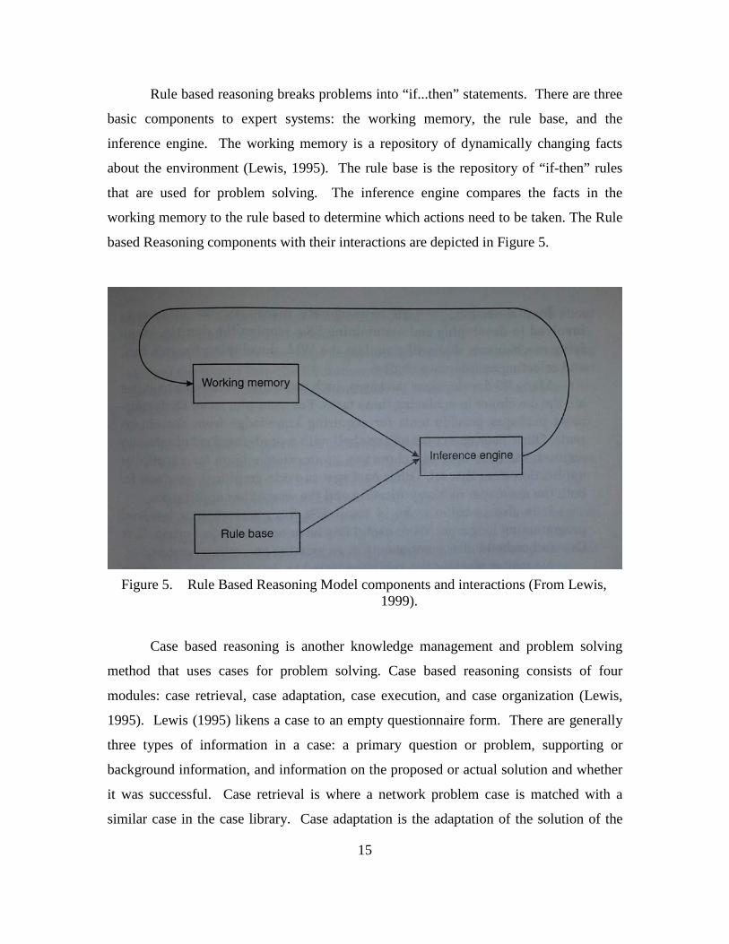
Rule based reasoning breaks problems into “if...then” statements. There are three
basic components to expert systems: the working memory, the rule base, and the
inference engine. The working memory is a repository of dynamically changing facts
about the environment (Lewis, 1995). The rule base is the repository of “if-then” rules
that are used for problem solving. The inference engine compares the facts in the
working memory to the rule based to determine which actions need to be taken. The Rule
based Reasoning components with their interactions are depicted in Figure 5.
Figure 5. Rule Based Reasoning Model components and interactions (From Lewis,
1999).
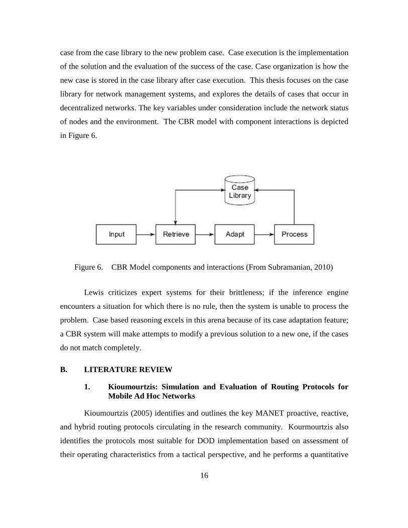
Case based reasoning is another knowledge management and problem solving
method that uses cases for problem solving. Case based reasoning consists of four
modules: case retrieval, case adaptation, case execution, and case organization (Lewis,
1995). Lewis (1995) likens a case to an empty questionnaire form. There are generally
three types of information in a case: a primary question or problem, supporting or
background information, and information on the proposed or actual solution and whether
it was successful. Case retrieval is where a network problem case is matched with a
similar case in the case library. Case adaptation is the adaptation of the solution of the
16
case from the case library to the new problem case. Case execution is the implementation
of the solution and the evaluation of the success of the case. Case organization is how the
new case is stored in the case library after case execution. This thesis focuses on the case
library for network management systems, and explores the details of cases that occur in
decentralized networks. The key variables under consideration include the network status
of nodes and the environment. The CBR model with component interactions is depicted
in Figure 6.
Figure 6. CBR Model components and interactions (From Subramanian, 2010)
Lewis criticizes expert systems for their brittleness; if the inference engine
encounters a situation for which there is no rule, then the system is unable to process the
problem. Case based reasoning excels in this arena because of its case adaptation feature;
a CBR system will make attempts to modify a previous solution to a new one, if the cases
do not match completely.
B. LITERATURE REVIEW
1. Kioumourtzis: Simulation and Evaluation of Routing Protocols for Mobile Ad Hoc Networks
Kioumourtzis (2005) identifies and outlines the key MANET proactive, reactive,
and hybrid routing protocols circulating in the research community. Kourmourtzis also
identifies the protocols most suitable for DOD implementation based on assessment of
their operating characteristics from a tactical perspective, and he performs a quantitative
17
analysis of those selected protocols using simulation software. Qualitative metrics used
in evaluation included loop-free behavior, unidirectional link support, and multicasting
ability. Based on the advantages and disadvantages of each protocol, he determines that
of the current MANET routing protocols, the Ad-Hoc On Demand Distance Vector
(AODV), the Dynamic Source Routing (DSR), and the Optimized Link State Routing
(OSLR) protocols were most suitable to the DoD, and those protocols were tested in his
computer simulation. Quantitative metrics recorded in the simulation included packet
delivery ratio, average end-to-end-delay, normalized routing load, and normalized MAC
load. Kioumourtzis concluded that there is no one best routing solution that performs
best in all tactical scenarios. Therefore, it is incumbent on network managers to
understand each protocol’s tradeoffs over the spectrum of situations. OLSR is optimal in
situations of low network congestion for delivering voice and video transmissions;
AODV is more suitable in networks with high mobility and connectivity that consist of
90 or more nodes; and DSR performs best in situations with high connectivity, a small
number of nodes (up to 100) and low mobility (Kiourmourtzis, 2005).
2. Bordetsky and Hayes-Roth: Extending the OSI Model for Wireless Battlefield Networks: a Design Approach to The 8th Layer For Tactical Hypernodes
Bordetsky and Hayes-Roth (2007) propose a network management scheme to
implement Command and Control in a network centric environment. Bordetsky in his
past experiments demonstrated an autonomous capability to link multiple human-ran
Network Operating Centers (NOCs) over large distances (up to 100 miles apart) using
unmanned aerial vehicles to plug gaps in coverage. The Network Operation Center
functions become extremely difficult when individual nodes are moving at rapid rates of
speed; such conditions create rapidly changing network situations that cannot be
adequately managed by humans due to delays in information travel time between nodes
and processing time within nodes. As a result, the authors propose the addition of an
18
eighth layer1 with “hypernodes” that individually act as NOCs. The hypernodes would
be able to perform three major functions associated with the telecommunications
management network model: Network Element Management and Network Management,
Service Management, and Business Management. The Simple Network Management
Protocol is already used to implement Network Element and Network Management. Its
network management capability could be theoretically extended to include a fault
management capability, which utilizes resident memory in the form of cases based on
Lundy Lewis’ Case-Based Reasoning approach.
3. Gateau: Extending Simple Network Management Protocol Beyond Network Management: A MIB Architecture for Network-Centric Services
Gateau (2007) describes the utility, simplicity, universality, security, and
extendibility of SNMP for network management. Gateau expands Albert’s (1999) three
domains of information flow, adding two domains (i.e., the technological and decision
support domains) that act as interfaces between the physical, information, and cognitive
domains. The technological domain nests itself between the physical and information
domains, and comprises those specific technologies that process, store, and manage data
and information. The decision support domain resides between the informational and
cognitive domains and shapes information into a useful form for processing in the
cognitive domain.
Gateau sees utility in Bordetsky and Hayes-Roth’s eighth layer concept and the
use of hypernodes performing two Telecommunications Management Network (TMN)
model functions. Service-management level aware hypernodes can be queried via SNMP
about network services available and the status of the aforementioned services, and
network element level (sub-network) aware hypernodes can maintain the status (up or
down) of all nodes attached to their sub-network. Gateau also describes a decision
support function where hypernodes can either send decisions or be queried on decisions
1 The OSI Model is an abstract representation that describes how network communications occur
(Dean, 2013). It contains seven layers: physical, data link, network, transport, session, presentation, and application layers. Bordetsky and Hayes Roth propose an additional layer that exists above the application layer. For more information on the OSI Model and its individual layers, see Dean (2013).
19
made by humans regarding the network. Gateau analyzes a Maritime Interdiction
Operations (MIO) experiment from a network management perspective, categorizing the
types of messages sent in the management process. He observed nine categories of
messages: requests for service, requests for information, responses/amplifications,
unsolicited information, network registration/deregistration, service/status
announcements, decision requests, decision announcements/ task assignments, and
situation reports. Gateau creates an architecture for three types of hypernodes that would
handle these types of messages: a service aware hypernode, a subnetwork aware
hypernode, and a decision support aware hypernode. His design includes a MIB for each
type of node.
4. Gruber: Integration and Management of Emerging Tactical Mesh Networks Combined with Unattended Sensor Networks, Ultra-Wideband Links, and Ad-Hoc Mobile Tactical Radios.
Gruber (2011) evaluates the effects on ultra-wideband propagation in shipboard
and urban environments, and assesses the capabilities of sensor and radio MANETS to
provide reliable transmission of sensor information to tactical operations centers. Based
on the above context, he evaluated two systems: the Trident Systems Ultra-Wideband
(UWB) Recce Node Unattended Ground Sensors and the TrellisWare CheetahNet TW-
220 radio systems. The Trident System was tested in both environments, while the
CheetahNet radio was tested in a shipboard environment. The Trident system did not
show a significant penetration capability (i.e., the ability of a signal to pass through solid
objects, such as walls) in either environment but produced throughputs in the 16 Mbps
range. The CheetahNet radios, under LOS conditions in the shipboard environment,
produced throughput in the 68–97 Kbps range. Gruber’s assessment was that the data
rate of the CheetahNet 220s was insufficient to provide a reliable reach back capability
(i.e., the ability to transmit video and other forms of data that require higher data rates
and do not react well to high jitter rates). Gruber also provides an overview of both
systems Network Management Capabilities, and recommends a new network
management capability that consists of a SNMP manager-agent network architecture. The
SNMP architecture would use a case-based reasoning system to automate network
20
management functions, with case information being available through local MIBs.
Gruber also recommends potential case information, including Position Location
Information, link health, network health, and bandwidth availability. Given these
elements, MANET nodes could position themselves to optimize the operation of the
network without human intervention.
5. Puff: Network Management System for Tactical Mobile Ad-Hoc Network Segments
Puff (2011) assesses the value of Tactical Mobile Ad-hoc Networks to the Marine
Corps’ Enhanced Marine Air Ground Task Force (MAGTF) Operations / Enhanced
Company Operations concepts. Puff also establishes a theory of how a Network
Management System (NMS) could be used to obtain even more value out of MANETs.
Puff theorizes that Bordetsky & Hayes Roth's (2007) hypernode operating at the eighth
layer could perform decentralized network management for MANETs. Hypernodes
would request information from other network nodes and change the values of certain
properties of those nodes by altering one or more variables in a node’s SNMP
Management Information Base (MIB). Since SNMP is an extensible protocol2,
additional network management specific variables can be included in a network agent’s
MIB. Puff identifies fifteen such variables that a hypernode would use to monitor, and
when necessary, improve network performance.
6. Rivera: Distributed Agent Based Networks in Support of Advanced Marine Corps Command and Control Concept
Rivera (2012) suggests that the tactical nature of combat and its communications
support infrastructure have a symbiotic relationship where operational success depends
on the network, and the network depends on the operation’s execution. Rivera puts forth
a hybrid network management model that combines both hierarchical and decentralized
architectures, using network management nodes that employ contextual analysis and
case-based reasoning to solve network problems. This hybrid system is called an
2 SNMP is extensible in that new functionality can be added to the protocol through the creation of
new variables to represent properties of a managed system.
21
autonomic system, where policy-based network management functions establish overall
objectives, and contextual information is used by the system to adapt the network
structure in accordance with established policies. Rivera hypothesizes that the Signal-to-
Noise Ratio (SNR) hop count, and power output are good indicators of network quality
and availability, and therefore are an important tool in the predictive network
management of MANETs.
Rivera observed the SNRs of TrellisWare CheetahNet TW-220 radios in the field
using the HEAT Map interface created by research in NPS’ CENETIX lab. Rivera
concludes that to evolve from managed networks to autonomic networks, a mechanism
that enables predictive and adaptive capabilities is required; however, Rivera does not
create an example of such a mechanism. Rivera posits that these capabilities (policy
creation, policy execution, and contextual awareness) must exist in every node in the
network.
The background and literature review provided a foundation for understanding
networks and network management systems. The research that led to the background
section helped me to grasp the concept and operation of MANETs. In addition, the
literature review helped me to identify gaps in research which led to the formulation of
the problem analyzed in this thesis. The conduct of the literature review also gave me a
basic understanding of the TrellisWare CheetahNet family of radios, but in order to really
experiment with them, a much deeper understanding of the radio systems and underlying
technology was required.

22
THIS PAGE INTENTIONALLY LEFT BLANK
23
III. RESEARCH METHODOLOGY
The concept examined by this thesis is that each node in the MANET has the
requisite information to execute hypernode behavior in maintaining connectivity. An
intelligent routing scheme that uses ad hoc routing techniques that take into account
energy efficiency and link quality in establishing routes is the first part of the goal; the
second part is establishing a case based reasoning scheme that takes into account specific
routing environmental factors to determine the best routing scheme. Given this approach,
the research methodology consists of three phases: the platform research and hands-on
familiarization with the data and voice communication capabilities of the system, an
analysis from a traditional network management perspective, and finally a determination
of metrics and variables for routing approaches and cases.
A. THE TRELLISWARE CHEETAHNET II TW-230 RADIO
TrellisWare Technologies, Inc. is a privately held communications company
headquartered in San Diego. Spun-off from ViaSat in April 2000, TrellisWare operates
as an independent business focused on cultivating solutions for ground communications
problems. Self-funded since its inception, TrellisWare specializes in advanced
communication algorithms, waveforms, and turn-key communication systems
(https://www.trellisware.com).
The TrellisWare CheetahNet radio system is a software-defined, barrage relay
network of radios that incorporate autonomous cooperation, and physical layer switching
to accomplish reliable communications in the harshest of radio-frequency (RF)
environments (Halford & Chugg, 2010). The radio systems employ a Dynamic Network
Architecture (DNA) at the Media Access Control Layer and above, implementing
multiple protocol models that enable distributed control (Blair, Brown, Chugg, &
Johnson, 2007). The system uses a time-division multiple-access (TDMA) method to
maximize use of the available bandwidth; this function is enhanced by a Physical Layer
(PHY) capability to combine a message sent by multiple sources as if they were sent by
24
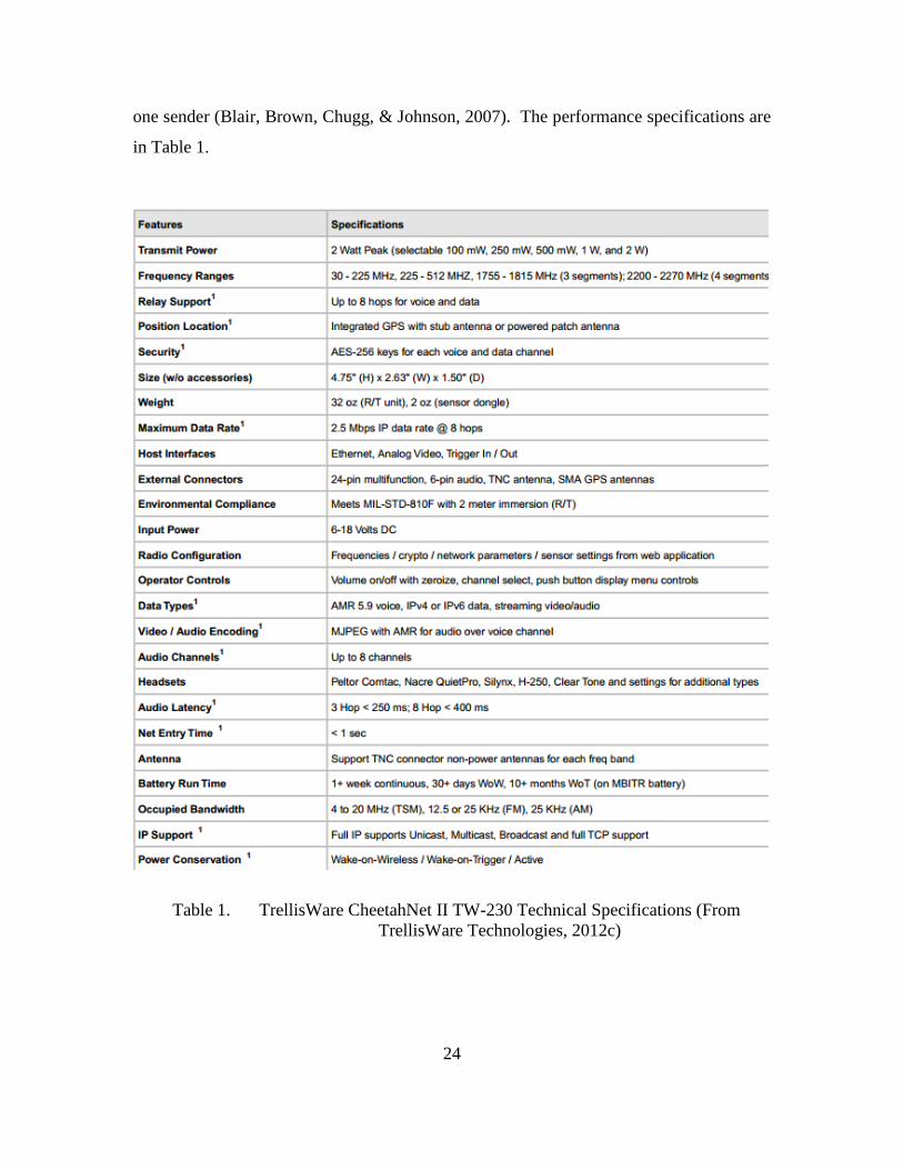
one sender (Blair, Brown, Chugg, & Johnson, 2007). The performance specifications are
in Table 1.
Table 1. TrellisWare CheetahNet II TW-230 Technical Specifications (From TrellisWare Technologies, 2012c)
25
Reading about the specifications was not enough to fully understand the radio
systems; hands-on time was necessary. With that in mind, multiple hours were spent in
learning to setup and operate the radios. There were twenty four radios available from
the CENETIX laboratory allocated for this purpose. The radio setup process is
complicated; however, the process for setting up multiple radios is facilitated by their
ability to be programmed simultaneously using a Cisco switch. Each radio is assigned a
Class A network IP address with a network prefix of 10.1.XXX.XXX. In the true sense
of classful addressing this is not a Class A address because only two octets are provided
for the host addressing. The IP addresses for the radios used in the laboratory were
already marked on each individual radio; if they were not, TrellisWare provides a method
of determining the numbers in the last two octets in the MANET Mission Configuration
(MMC) guide. When the radios are attached to the router, a laptop with an Ethernet
connection can connect to all the radios via the Cisco switch. That occurs provided that
the following conditions exist: the laptop’s IP address for the Ethernet Network Interface
Card (NIC) must be the same network address as the radios, the NICs subnetwork mask
must be hard-coded in as 255.000.000.000, TrellisWare’s default certificates must be
installed in the Internet browser used to access the radio, and the radios must be placed in
“programming mode.”
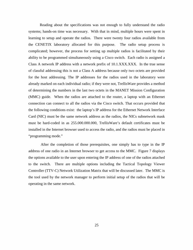
After the completion of those prerequisites, one simply has to type in the IP
address of one radio in an Internet browser to get access to the MMC. Figure 7 displays
the options available to the user upon entering the IP address of one of the radios attached
to the switch. There are multiple options including the Tactical Topology Viewer
Controller (TTV-C) Network Utilization Matrix that will be discussed later. The MMC is
the tool used by the network manager to perform initial setup of the radios that will be
operating in the same network.
26
Figure 7. TrellisWare Web Application Screen (From TrellisWare Technologies,
2012b)
1. Mobile Ad-Hoc Network Mission Configuration Tool
The Mobile Ad-Hoc Network Mission Configuration Tool contains everything the
network manager needs to perform initial configuration of the radios. Radio
Configuration is based on five main areas: device configuration, communications
security, wideband settings, narrowband settings, sensor settings, and gateway settings.
The device settings allow the network manager to set parameters such as the power
output, the node’s alias (name), establish the type of power source used (battery versus
direct connection to power source), GPS coordinate type (MGRS, UTM, Lat/Long, etc.),
and many other factors. Even the type of headset used with the radio is configurable.
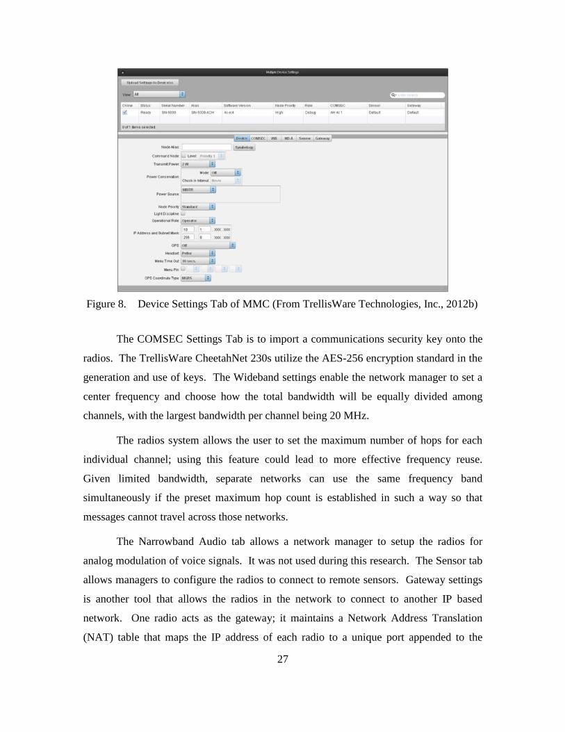
The device settings tab on the MMC tool is shown in Figure 8.
27
Figure 8. Device Settings Tab of MMC (From TrellisWare Technologies, Inc., 2012b)
The COMSEC Settings Tab is to import a communications security key onto the
radios. The TrellisWare CheetahNet 230s utilize the AES-256 encryption standard in the
generation and use of keys. The Wideband settings enable the network manager to set a
center frequency and choose how the total bandwidth will be equally divided among
channels, with the largest bandwidth per channel being 20 MHz.
The radios system allows the user to set the maximum number of hops for each
individual channel; using this feature could lead to more effective frequency reuse.
Given limited bandwidth, separate networks can use the same frequency band
simultaneously if the preset maximum hop count is established in such a way so that
messages cannot travel across those networks.
The Narrowband Audio tab allows a network manager to setup the radios for
analog modulation of voice signals. It was not used during this research. The Sensor tab
allows managers to configure the radios to connect to remote sensors. Gateway settings
is another tool that allows the radios in the network to connect to another IP based
network. One radio acts as the gateway; it maintains a Network Address Translation
(NAT) table that maps the IP address of each radio to a unique port appended to the
28
gateway radio’s IP address. The sensor settings and the gateway settings were not used
in this research also.
2. Tactical Topology Viewer Controller
The TTV-C enables the network manager to monitor the performance of the
network radios and to perform some limited network element management. The TTV-C
allows the network Manager to (TrellisWare Technologies, Inc., 2012a):
1. See information on alerts--such as breaks in node links, and low battery
levels
2. Visualize the locations of the network nodes on a map
3. See specific information on each node operating in a network, such as
node aliases, IP addresses, MAC addresses, and GPS grid locations (if
enabled)
4. Observe the quality of the links between nodes3
5. Perform over the air rekeying and zeroing (not used in this research)
6. Observe and configure remote media streams (not used in this research)
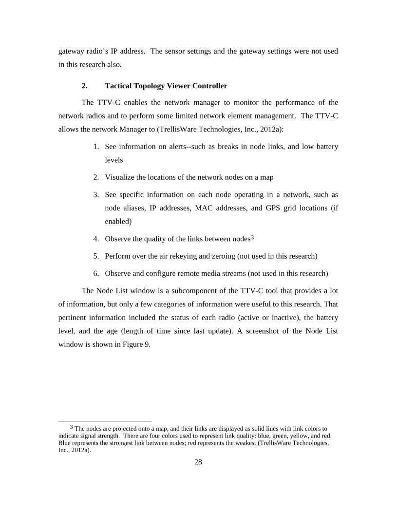
The Node List window is a subcomponent of the TTV-C tool that provides a lot
of information, but only a few categories of information were useful to this research. That
pertinent information included the status of each radio (active or inactive), the battery
level, and the age (length of time since last update). A screenshot of the Node List
window is shown in Figure 9.
3 The nodes are projected onto a map, and their links are displayed as solid lines with link colors to
indicate signal strength. There are four colors used to represent link quality: blue, green, yellow, and red. Blue represents the strongest link between nodes; red represents the weakest (TrellisWare Technologies, Inc., 2012a).
29
Figure 9. TTVC Node List and Remote Media Stream Windows
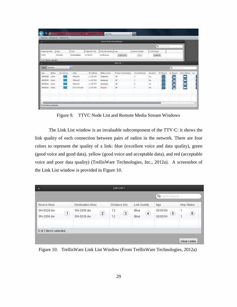
The Link List window is an invaluable subcomponent of the TTV-C: it shows the
link quality of each connection between pairs of radios in the network. There are four
colors to represent the quality of a link: blue (excellent voice and data quality), green
(good voice and good data), yellow (good voice and acceptable data), and red (acceptable
voice and poor data quality) (TrellisWare Technologies, Inc., 2012a). A screenshot of
the Link List window is provided in Figure 10.
Figure 10. TrellisWare Link List Window (From TrellisWare Technologies, 2012a)
30
B. RESEARCH DESIGN
The Barrage Relay scheme incorporating TDMA gives the CheetahNet II TW-230
radios a great advantage in providing robust communications. The tradeoff for this
capability is in spectral effectiveness and energy efficiency.
Barrage Relay causes nodes that are not linked between the source and destination
node to unnecessarily forward messages, wasting output power. In addition, TDMA is a
capable multiple access mechanism, but it does not adapt to changes in the quantity of
active users.
The radio system’s network management capabilities, when compared to the
functionality described in the Telecommunications Management Network (TMN) model
(Subramanian, 2010), allow for some modest configuration changes only at the network
element layer. A more energy efficient paradigm would take into account the battery life
of the individual nodes, and it would use only the necessary bandwidth resources when
they are needed. A more spectrally effective paradigm would maximize the use of
available bandwidth as necessary. Barrage Relay networks do not accomplish either for
two main reasons: (1) Barrage Relay networks use every node to broadcast a message it
receives, hence situations arise when nodes re-broadcast messages received that have no
chance of getting to the intended destination through the intermediate node, and (2)
Barrage Relay networks use Time Division Multiple Access (TDMA) to allocate each
node time to broadcast its message. In the event that a network’s node density is low, a
large number of time slots are not being used for transmission or reception. Essentially,
time is being wasted that could be allocated for message transmission.
An Ad Hoc intelligent routing scheme, when coupled with a case based reasoning
system that takes into account specific factors in the scheme of maneuver represents a
solid alternative to the Barrage Relay scheme. The Ad Hoc routing scheme requires a
routing metric to evaluate possible routes for efficiency. A routing metric that takes into
account both the battery life of the intermediate node and the SNR between links (both
factors are equally weighted) is displayed in Figure 11. SNR represents the Signal to
Noise Ratio of the Link between a transmitter and receiver expressed in decibels (dB).
31
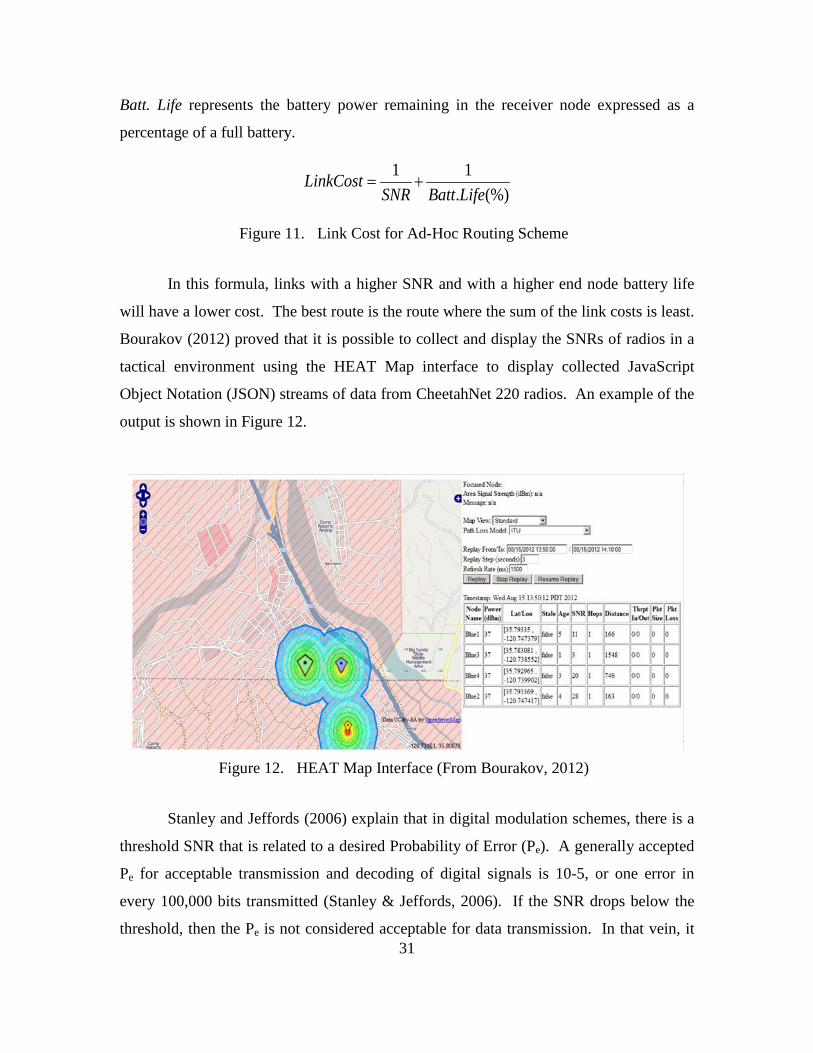
Batt. Life represents the battery power remaining in the receiver node expressed as a
percentage of a full battery.
1 1
. (%)LinkCost
SNR Batt Life= +
Figure 11. Link Cost for Ad-Hoc Routing Scheme
In this formula, links with a higher SNR and with a higher end node battery life
will have a lower cost. The best route is the route where the sum of the link costs is least.
Bourakov (2012) proved that it is possible to collect and display the SNRs of radios in a
tactical environment using the HEAT Map interface to display collected JavaScript
Object Notation (JSON) streams of data from CheetahNet 220 radios. An example of the
output is shown in Figure 12.
Figure 12. HEAT Map Interface (From Bourakov, 2012)
Stanley and Jeffords (2006) explain that in digital modulation schemes, there is a
threshold SNR that is related to a desired Probability of Error (Pe). A generally accepted
Pe for acceptable transmission and decoding of digital signals is 10-5, or one error in
every 100,000 bits transmitted (Stanley & Jeffords, 2006). If the SNR drops below the
threshold, then the Pe is not considered acceptable for data transmission. In that vein, it
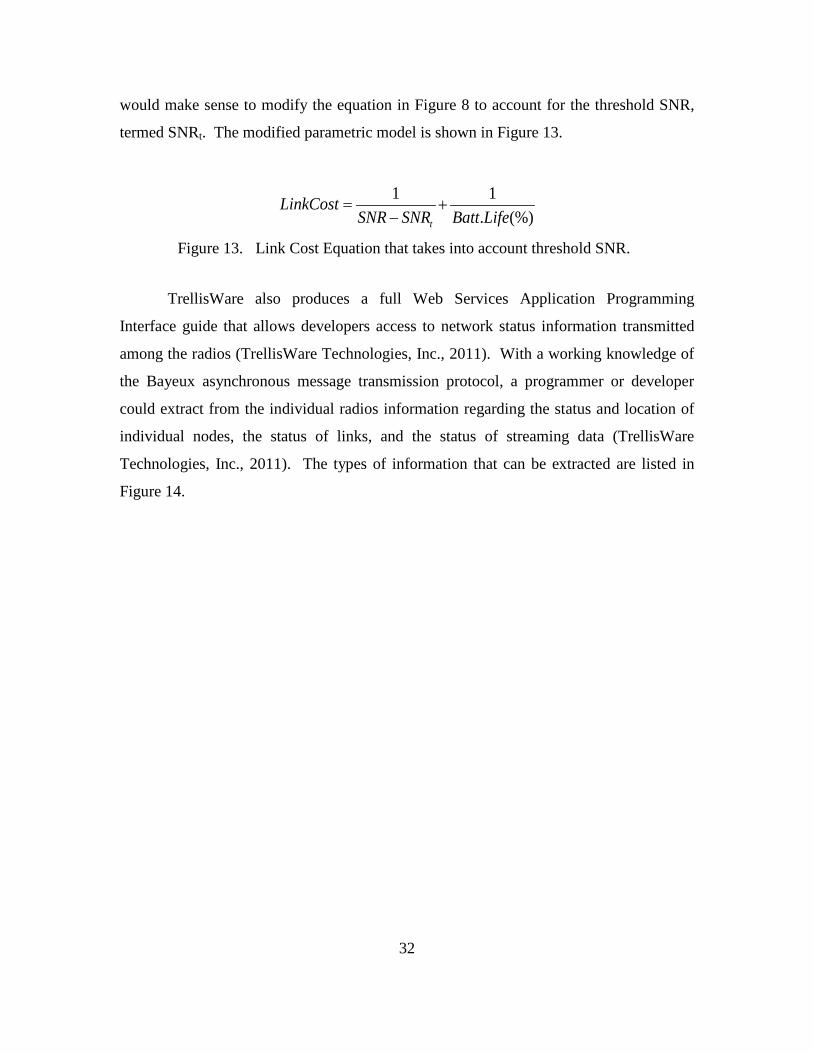
32
would make sense to modify the equation in Figure 8 to account for the threshold SNR,
termed SNRt. The modified parametric model is shown in Figure 13.
1 1. (%)t
LinkCostSNR SNR Batt Life
= +−
Figure 13. Link Cost Equation that takes into account threshold SNR.
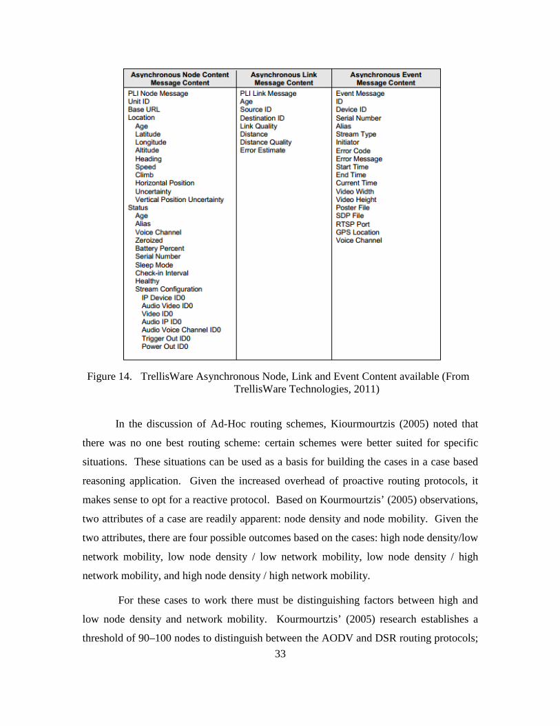
TrellisWare also produces a full Web Services Application Programming
Interface guide that allows developers access to network status information transmitted
among the radios (TrellisWare Technologies, Inc., 2011). With a working knowledge of
the Bayeux asynchronous message transmission protocol, a programmer or developer
could extract from the individual radios information regarding the status and location of
individual nodes, the status of links, and the status of streaming data (TrellisWare
Technologies, Inc., 2011). The types of information that can be extracted are listed in
Figure 14.
33
Figure 14. TrellisWare Asynchronous Node, Link and Event Content available (From
TrellisWare Technologies, 2011)
In the discussion of Ad-Hoc routing schemes, Kiourmourtzis (2005) noted that
there was no one best routing scheme: certain schemes were better suited for specific
situations. These situations can be used as a basis for building the cases in a case based
reasoning application. Given the increased overhead of proactive routing protocols, it
makes sense to opt for a reactive protocol. Based on Kourmourtzis’ (2005) observations,
two attributes of a case are readily apparent: node density and node mobility. Given the
two attributes, there are four possible outcomes based on the cases: high node density/low
network mobility, low node density / low network mobility, low node density / high
network mobility, and high node density / high network mobility.
For these cases to work there must be distinguishing factors between high and
low node density and network mobility. Kourmourtzis’ (2005) research establishes a
threshold of 90–100 nodes to distinguish between the AODV and DSR routing protocols;
34
based on his observations the lower threshold of 90 nodes can represent the boundary
between high and low node density. Mobility is not as clearly defined; this threshold can
be determined by examining the tactical use of these radios. At the tactical level,
combatants are either foot mobile or on vehicles. Personnel on foot cannot be expected
to travel faster than 15 miles per hour for extended periods, and that is a high threshold,
which would equate to a combatant moving at a four-minute-per-mile pace. Therefore,
nodes moving at speeds higher than 15 miles per hour (MPH) would be considered highly
mobile.
A tactical network will consist of multiple nodes operating at different speeds. In
order to accommodate that fact, it makes sense to look at the aggregate speed of the
nodes in the network when considering the criteria for CBR cases. A network where a
simple majority of nodes are operating at or above the threshold of 15 MPH can therefore
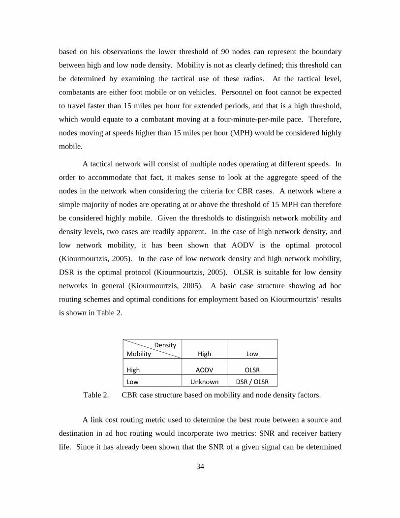
be considered highly mobile. Given the thresholds to distinguish network mobility and
density levels, two cases are readily apparent. In the case of high network density, and
low network mobility, it has been shown that AODV is the optimal protocol
(Kiourmourtzis, 2005). In the case of low network density and high network mobility,
DSR is the optimal protocol (Kiourmourtzis, 2005). OLSR is suitable for low density
networks in general (Kiourmourtzis, 2005). A basic case structure showing ad hoc
routing schemes and optimal conditions for employment based on Kiourmourtzis’ results
is shown in Table 2.
Density Mobility High Low
High AODV OLSR
Low Unknown DSR / OLSR
Table 2. CBR case structure based on mobility and node density factors.
A link cost routing metric used to determine the best route between a source and
destination in ad hoc routing would incorporate two metrics: SNR and receiver battery
life. Since it has already been shown that the SNR of a given signal can be determined
35
(Bourakov, 2012), the next step is to determine the threshold SNR for effective data
transmission. TrellisWare uses a link color scheme to depict the quality of link between
two nodes. Blue represents a link that is excellent for voice and data transmissions; green
represents a link that is capable of good voice and data quality; yellow represents a link
that has good voice quality and acceptable data quality; red represents a link that has
acceptable voice quality and poor voice quality (TrellisWare Technologies, Inc., 2012a).
The cases used to determine the best routing protocol for a particular situation also
provide variables that can be measured: node rate of movement (or speed), and node
density. Measuring these variables is the basis for the proof of concept.

36
THIS PAGE INTENTIONALLY LEFT BLANK
37
IV. EXPERIMENTATION AND RESULTS
The data for this thesis comes from two major test events. The first testing event
occurred at Camp Roberts, California. Data was collected from the operational testing of
the CheetahNet II TW-230 radios in a tactical scenario. The second testing event was
designed to collect and evaluate data collected from a tactical scenario conducted on the
grounds of the Naval Postgraduate School and in the local area surrounding it.
A. ENHANCED MAGTF OPERATIONS LIMITED OBJECTIVE EXPERIMENT 3
The Marine Corps Warfighting Lab (MCWL) has been performing experiments to
develop the MAGTF’s ability to conduct Distributed Operations (DO) (Marine Corps
Warfighting Laboratory, 2013). The CMCs guidance in the Marine Corps Vision and
Strategy 2025 (Conway, 2008) is the driving force behind MCWL’s research in
Enhanced MAGTF Operations (EMO). The strategy document directs the Marine Corps’
research organizations to “aggressively experiment with and implement new capabilities
and organizations” (Conway, 2008). The organizational structure and doctrine of the
MAGTF is changing such that capabilities previously believed to be only effective using
an infantry battalion (the Battalion Landing Team or BLT) can now be performed by a
company sized force (the Company Landing Team or CLT). LOE 3 is the result of the
evolution of the EMO experiments, building off previous DO, ECO, and EMO
experiments. EMO LOE 3 focuses on the fires aspect of EMO, whereas LOEs 1 and 2
focused on command and control and logistical support of EMO.
The goal of EMO LOE 3 was to create a synergy of fires on the distributed
battlefield. The experiment was built around the hypothesis that the effectiveness of Fire
Support for a sea-based force can improve dramatically with the right equipment (e.g.,
over-the-horizon (OTH) coordination and communications suites) and the training of key
personnel. The sea-based Fire Support organization in this experiment was the
Supporting Arms Coordination Center, responsible for integrating and managing
supporting fires during the initial landing of an amphibious force. Based on these
38
concepts, EMO LOE 3 was conducted from 9-19 May 2013. It assessed the capabilities
and Tactics, Techniques, and Procedures (TTPs) of MAGTF Fires using a combination of
current and newly developed technologies.
1. Concept of Employment
The Concept of Employment centered on a Mechanized/Motorized Company
Landing Team (CLT) and a Helo-borne CLT conducting an attack on two battalion
objectives. For this experiment, it was assumed that the ship-to-shore movement had
already occurred for both landing teams. Each CLT’s task organization included two Fire
Support Teams (FiSTs) and a company Fire Support Coordination Center (FSCC). The
Helo-borne CLT had an Expeditionary Fire Support System (EFSS) (120mm Mortar)
platoon attached, and the Mechanized/Motorized CLT had a M777 Towed Artillery
platoon attached. The FiSTs were tasked to prosecute planned targets and targets of
opportunity during the operation. The FSCC coordinated the employment of organic fire
support assets and supporting assets (e.g. Close Air Support). The Supporting Arms
Coordination Center (SACC) coordinated the employment of MAGTF Fires (e.g.,
HIMARS and Naval Gunfire) into the scheme of maneuver. The TrellisWare
CheetahNet II TW-230s were employed at the company level, providing intra-company
communications between the company FSCC, the FiSTs, and the weapons system
platoons (i.e., EFSS and M777). The Aerial Mobile Ad Hoc Networking Passive Relay
(AMPR) was utilized as a redundant relay for intra-company digital communications.
The AMPR is a small unmanned aerial system that houses the TrellisWare CheetahNet
CUB TW-4004. The AMPR’s objective was to fill in coverage gaps—e.g., breaks in
communication caused by terrain masking—to maintain a continuous network access.
This solution was designed to prevent single nodes or groups of nodes from being
isolated or disconnected from the main company network. Figure 15 provides a graphic
depiction of the scheme of maneuver.
4 The TrellisWare CUB TW-400 is similar to the TW-230 radio system, but it has a smaller form
factor. It uses TrellisWare’s Tactical Scalable MANET Enhanced (TSM-E) waveform, and is capable of encoding analog voice signals. For more information, see https://www.trellisware.com.
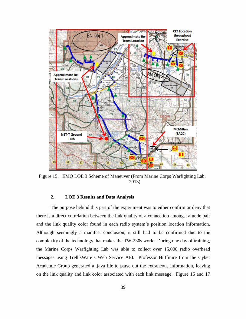
39
Figure 15. EMO LOE 3 Scheme of Maneuver (From Marine Corps Warfighting Lab,
2013)
2. LOE 3 Results and Data Analysis
The purpose behind this part of the experiment was to either confirm or deny that
there is a direct correlation between the link quality of a connection amongst a node pair
and the link quality color found in each radio system’s position location information.
Although seemingly a manifest conclusion, it still had to be confirmed due to the
complexity of the technology that makes the TW-230s work. During one day of training,
the Marine Corps Warfighting Lab was able to collect over 15,000 radio overhead
messages using TrellisWare’s Web Service API. Professor Huffmire from the Cyber
Academic Group generated a .java file to parse out the extraneous information, leaving
on the link quality and link color associated with each link message. Figure 16 and 17
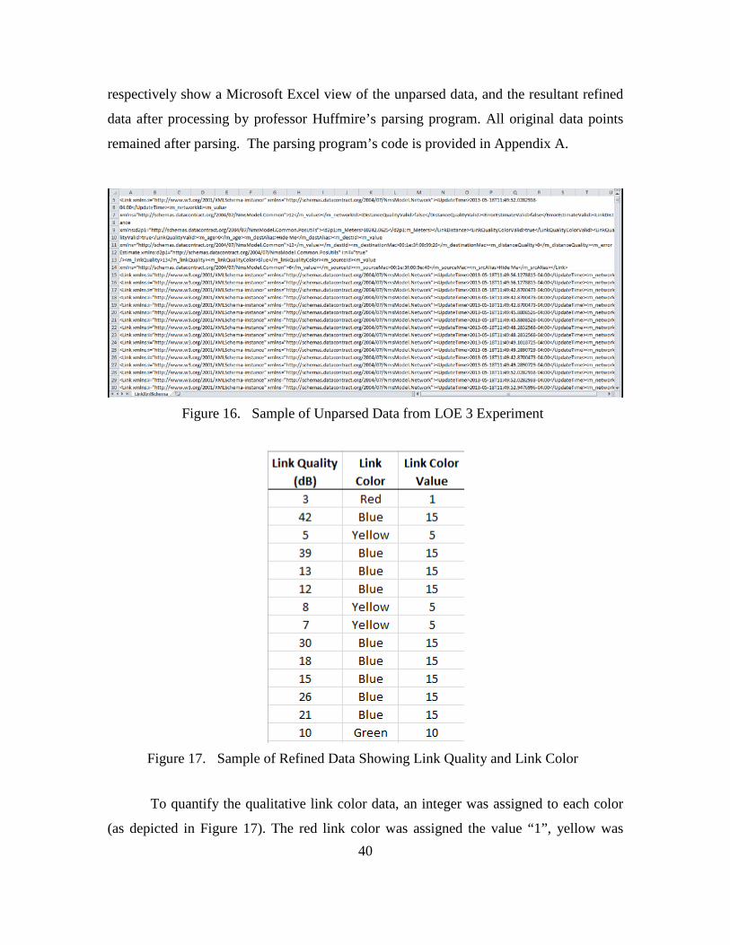
40
respectively show a Microsoft Excel view of the unparsed data, and the resultant refined
data after processing by professor Huffmire’s parsing program. All original data points
remained after parsing. The parsing program’s code is provided in Appendix A.
Figure 16. Sample of Unparsed Data from LOE 3 Experiment
Figure 17. Sample of Refined Data Showing Link Quality and Link Color
To quantify the qualitative link color data, an integer was assigned to each color
(as depicted in Figure 17). The red link color was assigned the value “1”, yellow was
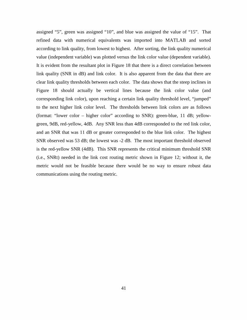
41
assigned “5”, green was assigned “10”, and blue was assigned the value of “15”. That
refined data with numerical equivalents was imported into MATLAB and sorted
according to link quality, from lowest to highest. After sorting, the link quality numerical
value (independent variable) was plotted versus the link color value (dependent variable).
It is evident from the resultant plot in Figure 18 that there is a direct correlation between
link quality (SNR in dB) and link color. It is also apparent from the data that there are
clear link quality thresholds between each color. The data shows that the steep inclines in
Figure 18 should actually be vertical lines because the link color value (and
corresponding link color), upon reaching a certain link quality threshold level, “jumped”
to the next higher link color level. The thresholds between link colors are as follows
(format: “lower color – higher color” according to SNR): green-blue, 11 dB; yellow-
green, 9dB, red-yellow, 4dB. Any SNR less than 4dB corresponded to the red link color,
and an SNR that was 11 dB or greater corresponded to the blue link color. The highest
SNR observed was 53 dB; the lowest was -2 dB. The most important threshold observed
is the red-yellow SNR (4dB). This SNR represents the critical minimum threshold SNR
(i.e., SNRt) needed in the link cost routing metric shown in Figure 12; without it, the
metric would not be feasible because there would be no way to ensure robust data
communications using the routing metric.
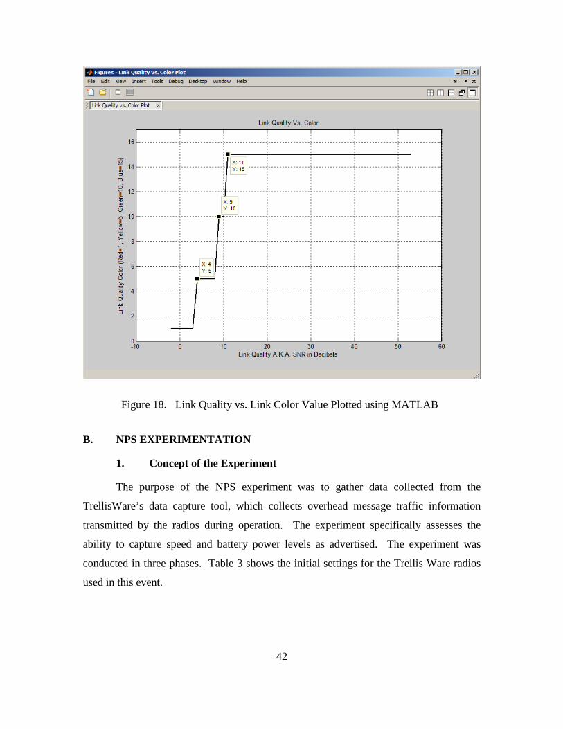
42
Figure 18. Link Quality vs. Link Color Value Plotted using MATLAB
B. NPS EXPERIMENTATION
1. Concept of the Experiment
The purpose of the NPS experiment was to gather data collected from the
TrellisWare’s data capture tool, which collects overhead message traffic information
transmitted by the radios during operation. The experiment specifically assesses the
ability to capture speed and battery power levels as advertised. The experiment was
conducted in three phases. Table 3 shows the initial settings for the Trellis Ware radios
used in this event.
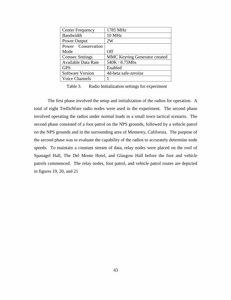
43
Center Frequency 1785 MHz Bandwidth 10 MHz Power Output 2W Power Conservation Mode
Off
Comsec Settings MMC Keyring Generator created Available Data Rate 540K / 8.75Mbs GPS Enabled Software Version 4d-beta safe-zeroize Voice Channels 1
Table 3. Radio Initialization settings for experiment
The first phase involved the setup and initialization of the radios for operation. A
total of eight TrellisWare radio nodes were used in the experiment. The second phase
involved operating the radios under normal loads in a small town tactical scenario. The
second phase consisted of a foot patrol on the NPS grounds, followed by a vehicle patrol
on the NPS grounds and in the surrounding area of Monterey, California. The purpose of
the second phase was to evaluate the capability of the radios to accurately determine node
speeds. To maintain a constant stream of data, relay nodes were placed on the roof of
Spanagel Hall, The Del Monte Hotel, and Glasgow Hall before the foot and vehicle
patrols commenced. The relay nodes, foot patrol, and vehicle patrol routes are depicted
in figures 19, 20, and 21
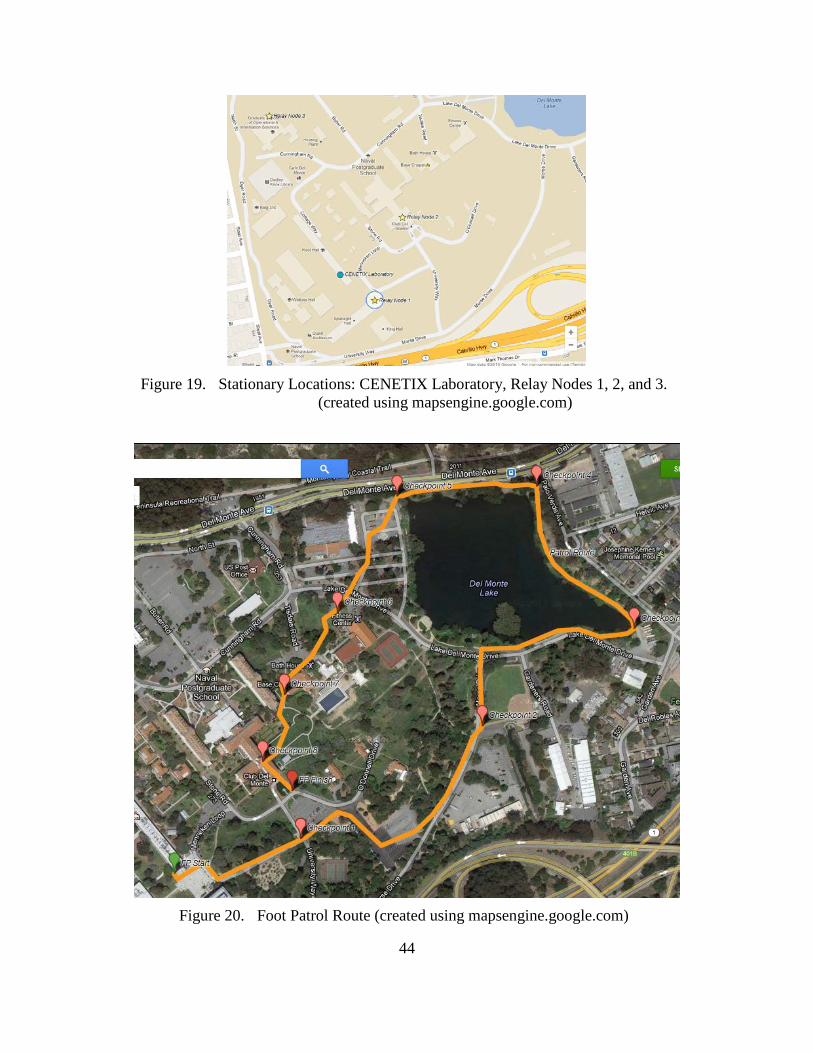
44
Figure 19. Stationary Locations: CENETIX Laboratory, Relay Nodes 1, 2, and 3.
(created using mapsengine.google.com)
Figure 20. Foot Patrol Route (created using mapsengine.google.com)
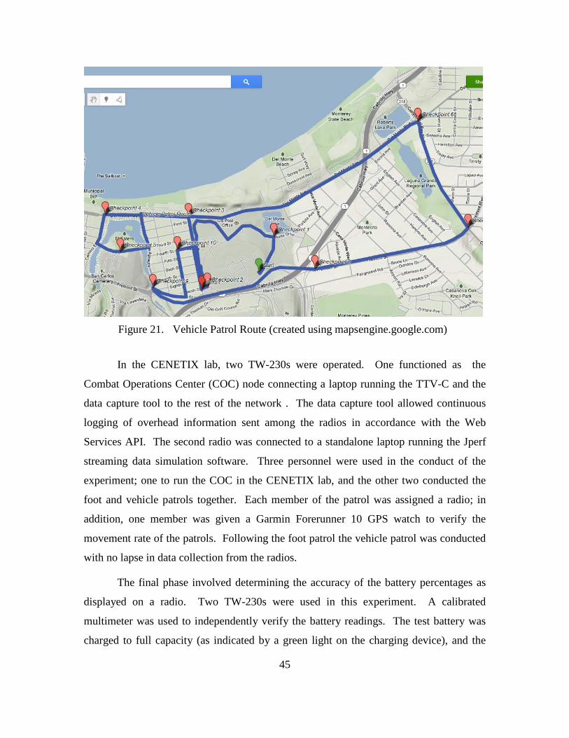
45
Figure 21. Vehicle Patrol Route (created using mapsengine.google.com)
In the CENETIX lab, two TW-230s were operated. One functioned as the
Combat Operations Center (COC) node connecting a laptop running the TTV-C and the
data capture tool to the rest of the network . The data capture tool allowed continuous
logging of overhead information sent among the radios in accordance with the Web
Services API. The second radio was connected to a standalone laptop running the Jperf
streaming data simulation software. Three personnel were used in the conduct of the
experiment; one to run the COC in the CENETIX lab, and the other two conducted the
foot and vehicle patrols together. Each member of the patrol was assigned a radio; in
addition, one member was given a Garmin Forerunner 10 GPS watch to verify the
movement rate of the patrols. Following the foot patrol the vehicle patrol was conducted
with no lapse in data collection from the radios.
The final phase involved determining the accuracy of the battery percentages as
displayed on a radio. Two TW-230s were used in this experiment. A calibrated
multimeter was used to independently verify the battery readings. The test battery was
charged to full capacity (as indicated by a green light on the charging device), and the
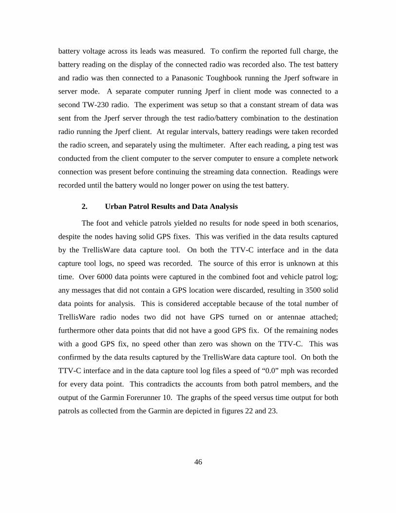
46
battery voltage across its leads was measured. To confirm the reported full charge, the
battery reading on the display of the connected radio was recorded also. The test battery
and radio was then connected to a Panasonic Toughbook running the Jperf software in
server mode. A separate computer running Jperf in client mode was connected to a
second TW-230 radio. The experiment was setup so that a constant stream of data was
sent from the Jperf server through the test radio/battery combination to the destination
radio running the Jperf client. At regular intervals, battery readings were taken recorded
the radio screen, and separately using the multimeter. After each reading, a ping test was
conducted from the client computer to the server computer to ensure a complete network
connection was present before continuing the streaming data connection. Readings were
recorded until the battery would no longer power on using the test battery.
2. Urban Patrol Results and Data Analysis
The foot and vehicle patrols yielded no results for node speed in both scenarios,
despite the nodes having solid GPS fixes. This was verified in the data results captured
by the TrellisWare data capture tool. On both the TTV-C interface and in the data
capture tool logs, no speed was recorded. The source of this error is unknown at this
time. Over 6000 data points were captured in the combined foot and vehicle patrol log;
any messages that did not contain a GPS location were discarded, resulting in 3500 solid
data points for analysis. This is considered acceptable because of the total number of
TrellisWare radio nodes two did not have GPS turned on or antennae attached;
furthermore other data points that did not have a good GPS fix. Of the remaining nodes
with a good GPS fix, no speed other than zero was shown on the TTV-C. This was
confirmed by the data results captured by the TrellisWare data capture tool. On both the
TTV-C interface and in the data capture tool log files a speed of “0.0” mph was recorded
for every data point. This contradicts the accounts from both patrol members, and the
output of the Garmin Forerunner 10. The graphs of the speed versus time output for both
patrols as collected from the Garmin are depicted in figures 22 and 23.
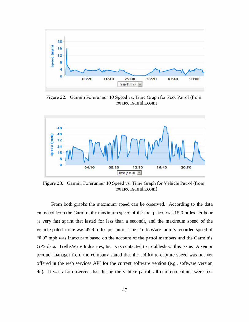
47
Figure 22. Garmin Forerunner 10 Speed vs. Time Graph for Foot Patrol (from
connect.garmin.com)
Figure 23. Garmin Forerunner 10 Speed vs. Time Graph for Vehicle Patrol (from
connect.garmin.com)
From both graphs the maximum speed can be observed. According to the data
collected from the Garmin, the maximum speed of the foot patrol was 15.9 miles per hour
(a very fast sprint that lasted for less than a second), and the maximum speed of the
vehicle patrol route was 49.9 miles per hour. The TrellisWare radio’s recorded speed of
“0.0” mph was inaccurate based on the account of the patrol members and the Garmin’s
GPS data. TrellisWare Industries, Inc. was contacted to troubleshoot this issue. A senior
product manager from the company stated that the ability to capture speed was not yet
offered in the web services API for the current software version (e.g., software version
4d). It was also observed that during the vehicle patrol, all communications were lost
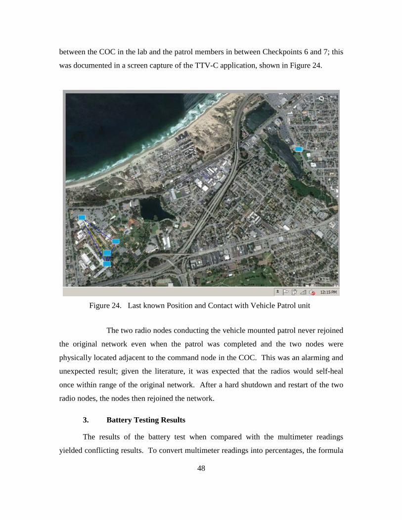
48
between the COC in the lab and the patrol members in between Checkpoints 6 and 7; this
was documented in a screen capture of the TTV-C application, shown in Figure 24.
Figure 24. Last known Position and Contact with Vehicle Patrol unit
The two radio nodes conducting the vehicle mounted patrol never rejoined
the original network even when the patrol was completed and the two nodes were
physically located adjacent to the command node in the COC. This was an alarming and
unexpected result; given the literature, it was expected that the radios would self-heal
once within range of the original network. After a hard shutdown and restart of the two
radio nodes, the nodes then rejoined the network.
3. Battery Testing Results
The results of the battery test when compared with the multimeter readings
yielded conflicting results. To convert multimeter readings into percentages, the formula
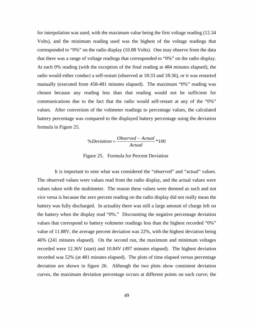
49
for interpolation was used, with the maximum value being the first voltage reading (12.34
Volts), and the minimum reading used was the highest of the voltage readings that
corresponded to “0%” on the radio display (10.88 Volts). One may observe from the data
that there was a range of voltage readings that corresponded to “0%” on the radio display.
At each 0% reading (with the exception of the final reading at 484 minutes elapsed), the
radio would either conduct a self-restart (observed at 18:33 and 18:36), or it was restarted
manually (executed from 458-481 minutes elapsed). The maximum “0%” reading was
chosen because any reading less than that reading would not be sufficient for
communications due to the fact that the radio would self-restart at any of the “0%”
values. After conversion of the voltmeter readings to percentage values, the calculated
battery percentage was compared to the displayed battery percentage using the deviation
formula in Figure 25.
% *100Observed ActualDeviationActual
−=
Figure 25. Formula for Percent Deviation
It is important to note what was considered the “observed” and “actual” values.
The observed values were values read from the radio display, and the actual values were
values taken with the multimeter. The reason these values were deemed as such and not
vice versa is because the zero percent reading on the radio display did not really mean the
battery was fully discharged. In actuality there was still a large amount of charge left on
the battery when the display read “0%.” Discounting the negative percentage deviation
values that correspond to battery voltmeter readings less than the highest recorded “0%”
value of 11.88V, the average percent deviation was 22%, with the highest deviation being
46% (241 minutes elapsed). On the second run, the maximum and minimum voltages
recorded were 12.36V (start) and 10.84V (497 minutes elapsed). The highest deviation
recorded was 52% (at 481 minutes elapsed). The plots of time elapsed versus percentage
deviation are shown in figure 26. Although the two plots show consistent deviation
curves, the maximum deviation percentage occurs at different points on each curve; the
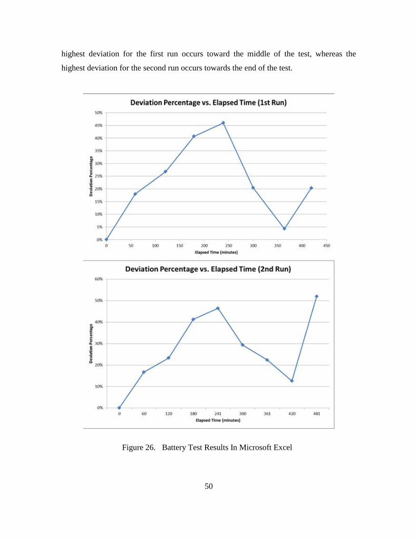
50
highest deviation for the first run occurs toward the middle of the test, whereas the
highest deviation for the second run occurs towards the end of the test.
Figure 26. Battery Test Results In Microsoft Excel

51
The implications of the battery test results specifically impact the accuracy of the
routing metric; it is extremely important in determining the most efficient route. The
battery test conclusions regarding accuracy would have more weight if more iterations
were conducted with different radios and batteries.

52
THIS PAGE INTENTIONALLY LEFT BLANK
53
V. CONCLUSIONS AND RECOMMENDATIONS FOR FURTHER RESEARCH
This research started out with a couple of goals in mind that were centered on the
necessary management tools to ensure that MANETs are able to support tactical
communications that are critical to the Marines Corps vision of future combat operations.
The main goal was that was developing a routing metric to evaluate alternate MANET
routing schemes. That metric was developed through a thorough review of the literature
and analysis of Marine Corps future communications requirements. This research
attempted to collect the necessary information needed to demonstrate that the routing
metric data was available. The routing metric is important for determining the cost of any
given route between the source and destination in a MANET, hence a vital piece of
information for using the most efficient route—a key element to mitigate the constraints
imposed by mobile, battery operated tactical radios. With that information, a discussion
of the benefit of different Ad-Hoc intelligent routing approaches was presented. A case
based reasoning approach was then put forth to exploit the potential that hypernodes
portend to the management of MANETs.
A. CONCLUSIONS
The conclusions of this thesis are developed from the investigation into the
following research questions. Each subsection below briefly explains the key rationale
for the question, the findings, and their implications to this, and future, research. .
What are the relevant factors in establishing the cost of each link for a given route between a source and destination?
The research reviewed in Chapters II and III proffers that when operating in a
bandwidth and energy constrained environment, it is important that an intelligent routing
scheme accounts for the SNR, the minimum threshold SNR for transmission of digital
signals, and the battery life of the destination node in a link, for bandwidth effective and
energy efficient transmissions. These findings are important because it provides a
foundation for alternate routing methods. Recommendations for further research would
54
involve using the aforementioned routing metric to determine the route cost between a
given source and destination in a MANET.
Can those factors be measured?
From the experimentation, the SNR between a link pair could be obtained from
the position location information in the overhead transmissions among the radios. It is
recommended that further research be conducted to verify the accuracy of SNR’s
presented by the radio system. The remaining battery percentage of a particular node was
also observed among the overhead messages logged by the data capture tool. The ability
to measure these factors allows a user or automated system to implement any ad hoc
routing algorithm. It is recommended that future research is conducted to validate the
accuracy of battery information obtained by the data logger tool. That research would
involve multiple iterations with different radios employing a combination of voice and
data transmissions in multiple environments.
How can a case-based reasoning (CBR) approach be applied to maximize the effectiveness of an intelligently routed MANET?
From the research in Chapters II and III it was determined that due to the highly
dynamic topology of the nodes in MANETs, multiple routing schemes should be
implemented because—to date—no one routing scheme has been shown to be optimal in
all conditions of dynamic MANETs. There is a tradeoff associated with each available
MANET routing scheme—i.e., each routing scheme performs differently depending on
network node density and aggregate node mobility levels. Based on the environment
and operational characteristics of the nodes in a MANET, a hypernode could determine
the optimal routing approach to be used, maximizing the effectiveness of the network in
multiple situations. That determination by the hypernode is contingent upon the
collection of accurate node density and speed information, and the classification of
aggregate network mobility based on individual nodes speeds. Recommendations for
future research would include the determination of additional network management tools
that CBR can implement in MANETs.
55
What are some key factors needed in a CBR case?
From the research, it was determined that some key factors of a MANET routing
CBR case include the node density and the speed of nodes in a network. These two
factors are what separate the operating capabilities of the different MANET routing
approaches. A hypernode that implements a CBR approach to network management
using these factors would maintain a robust network while simultaneously improving
efficiency over a barrage relay method. Recommendations for future research include
determining an ad hoc routing method that works best in the case of high node density /
low mobility networks.
Can CBR Case information be Captured using the System’s Current Network Management Platform?
The TrellisWare CheetahNet II TW-230 system, although designed and operated
using the Barrage Relay / TDMA routing scheme, still provided valuable information that
would be important in an intelligent routing protocol. The density of the network can be
observed at any time through the network management tools that accompany the
TrellisWare system. Given the number of nodes used in the NPS experiment (e.g., Figure
24) it was easy to confirm the number of nodes displayed at any given time. A more
rigorous evaluation would include larger quantities of nodes operating to verify the
accuracy of this feature over time.
Unfortunately, no node speed data for any node was obtained during the
experiments. The node speed was a critical factor needed in the implementation of the
CBR case structure developed in this thesis; without it, a hypernode would not be able to
determine the best ad hoc routing method based on the case. TrellisWare Technologies,
Inc. confirmed the lack of functionality and it is planned for future software versions for
the TrellisWare CheetahNet II TW-230 radios. Recommendations for future research
include studying the best method of characterizing network aggregate node speed for the
CBR case structure presented in this thesis.
56
B. RECOMMENDATIONS
From the experiments, it was determined that there is a direct correlation between
the SNR and link quality associated with a given link between nodes. The information
could be easily obtained from the TrellisWare’s network management software tools.
The battery life, in percentage levels, could also be obtained from the TrellisWare’s
network management system. The SNR and the Battery life of the nodes is a very
important finding; with those two metrics, the routing metric could be used to determine
the cost of a given route, and the costs of each route could be compared to determine the
most efficient route. Of the two factors deemed necessary to the structure of a CBR case
(i.e., node density and aggregate node mobility) only node density could be obtained.
Node mobility levels based on node speeds is definitely a recommendation for future
research when the functionality is added to the TrellisWare CheetahNet II TW-230 radio
system.
Other recommendations for research include a comparison of the TrellisWare
CheetahNet II TW-230 radio system to other MANET solutions of interest to the Marine
Corps, including the Wave Relay systems. An analysis that simulates the transmission of
a message in one of the Ad-Hoc protocols versus the Barrage Relay / TDMA
transmission scheme would also be beneficial to the Marine Corps in its quest for a next
generation communications system. In addition, the SNRs collected were obtained by the
radio system itself; an independent analysis evaluating the accuracy of SNR levels at the
receiving antenna would be beneficial as well.
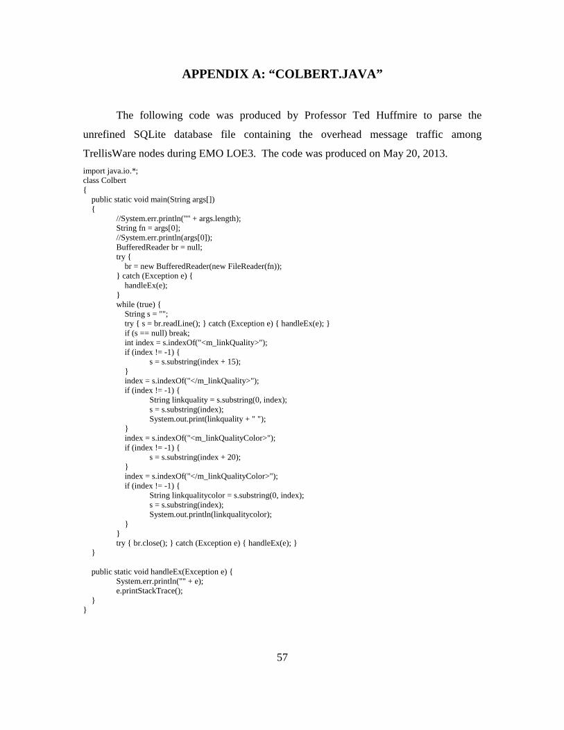
57
APPENDIX A: “COLBERT.JAVA”
The following code was produced by Professor Ted Huffmire to parse the
unrefined SQLite database file containing the overhead message traffic among
TrellisWare nodes during EMO LOE3. The code was produced on May 20, 2013. import java.io.*; class Colbert { public static void main(String args[]) { //System.err.println("" + args.length); String fn = args[0]; //System.err.println(args[0]); BufferedReader br = null; try { br = new BufferedReader(new FileReader(fn)); } catch (Exception e) { handleEx(e); } while (true) { String s = ""; try { s = br.readLine(); } catch (Exception e) { handleEx(e); } if (s == null) break; int index = s.indexOf("<m_linkQuality>"); if (index != -1) { s = s.substring(index + 15); } index = s.indexOf("</m_linkQuality>"); if (index != -1) { String linkquality = s.substring(0, index); s = s.substring(index); System.out.print(linkquality + " "); } index = s.indexOf("<m_linkQualityColor>"); if (index != -1) { s = s.substring(index + 20); } index = s.indexOf("</m_linkQualityColor>"); if (index != -1) { String linkqualitycolor = s.substring(0, index); s = s.substring(index); System.out.println(linkqualitycolor); } } try { br.close(); } catch (Exception e) { handleEx(e); } } public static void handleEx(Exception e) { System.err.println("" + e); e.printStackTrace(); } }

58
THIS PAGE INTENTIONALLY LEFT BLANK
59
SUPPLEMENTAL: DATA COLLECTED FROM MARINE CORPS WARFIGHTING LAB EXERCISE AND NPS EXPERIMENTS
The data collected from the experiments are contained in three Microsoft Excel
files. This data were analyzed for trends, resulting in the conclusions presented in
Chapter V.
The first file, titled “20130518MCWLtestresults_parsed.xlsx” is the collection of
data resulting from the Marine Corps Warfighting Lab’s Limited Objective Experiment
three. The original file is a text file and contained extraneous information. Professor Ted
Huffmire from the Cyber Academic Groups, created a java program named “colbert.java”
to remove the extraneous information, leaving behind the SNRs and the link color
associated with the received SNR.
The second file, titled “20130522NPStestresults_parsed.xlsx” contains the data
collected from the vehicle and foot patrols in a simulated urban environment aboard NPS
and Monterey. The original text file that contained the data was also parsed by a program
written by Professor Huffmire. The resultant Microsoft Excel file contained only the
necessary information for analysis of node battery and position location information:
battery percentage levels, GPS grid locations, and node speeds, although only speeds of
“0.0” were collected during the entire experiment.
The third file, titled “20130524_BatteryTestResults.xlsx” contains the data
collected from the third experiment in Chapter IV which entailed the charging and
discharging of a battery while recording the voltage levels and battery percentage levels
at regular intervals until the battery failed.
All data files are available at the Naval Postgraduate School’s Dudley Knox
Library for review.

60
THIS PAGE INTENTIONALLY LEFT BLANK
61
LIST OF REFERENCES
Alberts, D. S., Garstka, J. J., & Stein, F. P. (1999). Network centric warfare: Developing and leveraging information superiority. Washington, DC: National Defense University Press.
Basagni, S., Conti, M., Giordano, S., & Stojmenovic, I. (Eds.). (2004). Mobile ad-hoc networking. Piscataway, NJ: IEEE Press.
Belding-Royer, E. M. (2004). Routing approaches in mobile ad hoc networks. In S. Basagni, M. Conti, S. Giordano, & I. Stojmenovic (Eds.), Mobile ad hoc networking (pp. 275–297). Piscataway: IEEE Press.
Blair, A., Brown, T., Chugg, K. M., & Johnson, M. (2007). Tactical mobile mesh network system design. IEEE Military Communications Conference (pp. 1-7). Orlando, FL: IEEE.
Bordetsky, A., & Hayes-Roth, F. (2007). Extending the OSI Model for wireless battlefield networks: A design approach to the 8th layer for tactical hypernodes. International Journal of Network Design and Innovation,pp. 81-91.
Bourakov, E. (2012). Graphical user interface for mobile ad hoc networks. Monterey, CA: Naval Postgraduate School.
Clark, V., & Hagee, M. (2005). FORCEnet: A functional concept for the 21st century. Washington, D.C.: Department of the Navy.
Comer, D. (2009). Computer networks and internets.(5th Edition). Upper Saddle River, NJ: Pearson Education.
Conway, J. T. (2008). Marine Corps vision & strategy 2025. Washington, D.C.: Headquarters, Marine Corps.
Dean, T. (2013). Network+ Guide to Networks (6th Edition). Boston, MA: Course Technology, Cengage Learning.
Gateau, J. (2007). Extending Simple Network Management Protocol (SNMP) beyond network management: A MIB architecture for network-centric services. Master’s thesis, Monterey, CA: Naval Postgraduate School.
Halford, T. R., & Chugg, K. M. (2010). Barrage relay networks. Information Theory and Applications Workshop (pp. 1-8). IEEE.
Kiourmourtzis, G. (2005). Simulation and evaluation of routing protocols for mobile ad hoc networks (MANETs). Master’s thesis, Monterey, CA: Naval Postgraduate School.
62
Lewis, L. (1995). Managing computer networks: A case-based reasoning approach. Boston: Artech House.
Liu, J. J., & Chlamtac, I. (2004). Mobile ad-hoc networking with a view of 4G wireless: Imperatives and challenges. In S. Basagni, M. Conti, S. Giordano, & I. Stojmenovic (Eds.), Mobile Ad Hoc Networking (pp. 1-35). Piscataway, NJ: IEEE Press.
Marine Corps Warfighting Laboratory. (2013). Enhanced Marine Air Ground Task Force operations limited objective experiment three (LOE 3) letter of instruction. Quantico: United States Marine Corps.
Perkins, C. E., & Bhagwat, P. (1994). Highly dynamic destination-sequenced distance-vector routing (DSDV) for mobile computers. ACM SIGCOMM Computer Communication Review, 24(4), 234-244.
Puff, C. J. (2011). Network management system for tactical mobile ad-hoc network segments. Master’s thesis, Monterey, CA: Naval Postgraduate School.
Stanley, W. D., & Jeffords, J. M. (2006). Electronic communications: Principles and systems. Clifton Park: Thomson Delmar Learning.
Subramanian, M. (2010). Network management: Principles and practice. New Delhi: Pearson Education.
TrellisWare Technologies, Inc. (2011). Web services API documentation. San Diego: TrellisWare Technology, Inc.
TrellisWare Technologies, Inc. (2012a). Tactical Topology Viewer-Controller guide. San Diego.
TrellisWare Technologies, Inc. (2012b). MANET mission configuration guide. San Diego: TrellisWare Technologies, Inc.
TrellisWare Technologies, Inc. (2012c). User’s guide. San Diego: TrellisWare Technologies, Inc.
United States Marine Corps. (1996). MCDP 6: Command and control. Washington: Department of Defense.
Van Creveld, M. L. (1985). Command in war. Cambridge: Harvard University Press.
63
INITIAL DISTRIBUTION LIST
1. Defense Technical Information Center Ft. Belvoir, Virginia 2. Dudley Knox Library Naval Postgraduate School Monterey, California