Embed Size (px)
Citation preview
Furnace Improvements Services
www.heatflux.com 1
Fired heaters are major consumers of en-
ergy in the chemical process industries
(CPI) especially at petroleum refineries
and petrochemical plants. Accounting for
as much as 70% of total plant energy con-
sumption in some instances. While most
plant engineers and operators are aware of
the importance of controlling excess oxy-
gen in fired heaters, they often overlook a
key determinant of efficient heater opera-
tion; the control of their draft, namely, the
negative pressure inside the vessel with
respect to the atmosphere.
A recent survey indicates two
extremes in draft management. In most
fired heaters, the draft is maintained at
almost four times the value recommended.
At the other end of the spectrum, some
heaters run with no draft – in fact, with
positive pressure at the radiant arch (the
transition zone between the radiant and
convection sections). Neither situation is
desirable; they can cause considerable loss
of energy, and can even be hazardous.
Plants can save substantial amounts of en-
ergy by training operators in proper draft
control and making minor hardware modi-
fications. For a 100,000-bbl/d (BPD) refin-
ery in the U.S., even a 1% improvements
in thermal efficiency translates into energy
Combustion
Combustion, the exothermic reaction re-
sulting from rapid combination of fuel with
oxygen, produces heat and flue gases. Fuel
and air must be mixed thoroughly for com-
plete combustion. In theory, it is possible
to burn fuel completely with just the
stoichiometric amount of combustion air.
However, under actual operating condi-
tions, perfect mixing of fuel and air is not
possible within the short time that is in-
volved in combustion. If only the theoreti-
cal amount of combustion air were pro-
vided, then some fuel would not burn com-
pletely. So, excess air is needed, expressed
as a percentage of the theoretical quantity
of air required for perfect combustion. This
excess air shows up as excess oxygen in
the flue gas. Table 1 shows the effects of
excess air and stack temperature on the
thermal efficiency of the fired heater. As a
rule of thumb, every 10% increase in ex-
cess air reduces the heater efficiency by
almost 1%, whereas every 35oF reduction
in stack flue gas temperature increases
efficiency by 1%.
Burners
Burners start and maintain combustion, in
the firebox. They introduce fuel and air in
the correct proportions and mix them, pro-
savings of almost $500,000/yr. Automatic
draft control can improve the efficiency of
fired heaters if it is designed and installed
correctly. Before explaining how, we pro-
vide a brief refresher on the concepts in-
volved.
Fired Heaters
In a fired heater, the thermal energy liber-
ated by the combustion of fuel is trans-
ferred to fluids contained in tubular coils
within an internally insulated enclosure.
A typical fired heater consists of
three major components; the radiant sec-
tion, the convection section and the stack.
Figure 1 shows a typical cross-sectional
view of a vertical cylindrical fired heater.
The fired heater is fired by oil or gaseous
fuel. The process fluid, passing through
tubes in the heater, absorbs the heat mostly
by radiant heat transfer, and by convective
heat transfer from the flue gases.
The flue gases are vented to the
atmosphere through the stack. Burners are
located on the floor (as stylized in Figure
1) or on the sidewalls of the heaters. Com-
bustion air is drawn from the atmosphere.
Combustion is directly affected by the
draft.
Get the Most From Your Fired Heater
Though the functioning of these widely used heat-ers it appears simple, there is more to efficient operation than meets the eye. A common stum-bling block is the control of draft.
Ashutosh Garg Furnace Improvements
Originally appeared in: March 2004 issue,
Chemical Engineering Reprinted with publisher’s permission.
Furnace Improvements Services
www.heatflux.com 2
vide a source of ignition, and stabilize
the flame. How the air is supplied to the
burners is largely related to the concept
of draft, discussed in more detail now.
In most fired heaters, the burn-
ers are natural draft, as explained below.
These burners are the most dependent on
the draft, as all natural draft burners are
sized for a specific draft loss across the
burner. Providing a higher draft than that
design value will induce more air,
whereas providing lower draft will lead
to insufficient air for combustion.
The other type of burners used
in fired heaters is forced-draft burners
which get their air supply from a fan.
These are not dependent on the heater
draft.
There are also self-inspirating
pre-mix burners, used in special heaters
such as those for steam methane reform-
ing, or for ethane cracking. Most of these
burners are partially dependent on the
draft available in the heater.
Draft
Draft is the pressure differential between
air or flue gas in the heater and ambient
air. It materializes because hot flue gases
inside the firebox and stack are lighter
Get the most from your Fired Heater
than (and thus at lower pressure than) the
colder ambient air outside.
In a given situation, the theo-
retically available draft, in inches of wa-
ter column (inWC ) can be calculated as
follows:
Draft = 0.53 HP [(1/ Tambient) – (1/ Tflue gas)]
Where H is stack height in feet, P is at-
mospheric pressure in pounds per square
inch absolute (psia). Tambient is the ambi-
ent temperature in degrees Rankine and
Tflue gas is the flue gas temperature, in the
same units.
Combustion air is drawn into
the burners from the atmosphere, and hot
gas rises due to buoyancy and flows out
of the stack to the atmosphere. While
passing through the heater’s convection
section and the stack, flue gases encoun-
ter friction resistance, known collec-
tively as draft losses. Sufficient stack
height is given to provide the buoyancy
effect needed to overcome these losses,
and to ensure that pressure is always
negative inside the firebox.
There are four types of draft
systems in the fired heaters:
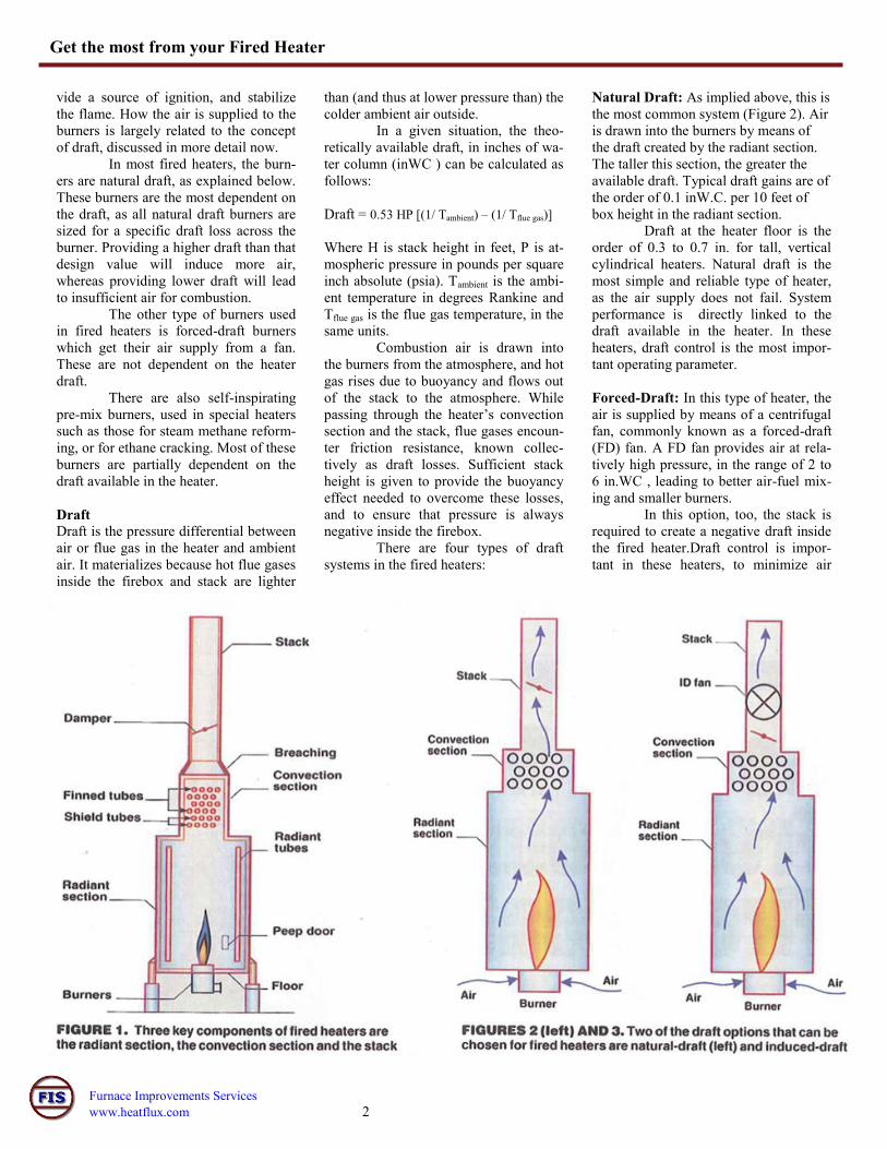
Natural Draft: As implied above, this is
the most common system (Figure 2). Air
is drawn into the burners by means of
the draft created by the radiant section.
The taller this section, the greater the
available draft. Typical draft gains are of
the order of 0.1 inW.C. per 10 feet of
box height in the radiant section.
Draft at the heater floor is the
order of 0.3 to 0.7 in. for tall, vertical
cylindrical heaters. Natural draft is the
most simple and reliable type of heater,
as the air supply does not fail. System
performance is directly linked to the
draft available in the heater. In these
heaters, draft control is the most impor-
tant operating parameter.
Forced-Draft: In this type of heater, the
air is supplied by means of a centrifugal
fan, commonly known as a forced-draft
(FD) fan. A FD fan provides air at rela-
tively high pressure, in the range of 2 to
6 in.WC , leading to better air-fuel mix-
ing and smaller burners.
In this option, too, the stack is
required to create a negative draft inside
the fired heater.Draft control is impor-
tant in these heaters, to minimize air
Furnace Improvements Services
www.heatflux.com 3
Get the most from your Fired Heater
leakage and to ensure negative pres-
sure throughout the whole heater.
Induced-Draft: When the height of
the stack is inadequate to compen-
sate for the draft-loss requirements,
an induced-draft (ID) fan is provided
on top of the fired heater (Figure 3).
The resulting negative pressure in-
side the heater ensures adequate
draft for the burners from the atmos-
phere. Most heaters in cracking and
reforming units fall into this cate-
gory. The size of the convection sec-
tion in these fired heaters is very
large, and the draft control is very
important.
Balanced-Draft: When both forced-
draft and induced-draft fans are used
the radiant section. In the convection
section, flue gases admittedly encounter
resistance due to tubes, but gain some
draft due to the height of this section. If
the convection section becomes fouled,
the pressure drop across that section
goes up and the draft at the arch can, in
fact, becomes positive.
Similarly in the stack, the stack
controls the draft. If the damper is closed
too far, the arch draft will become posi-
tive; if it is instead opened too far, it will
lead a very high draft in the arch. The
right stack height provides the draft need
to maintain negative pressure at the arch
and to take care of friction losses in the
convections section and stack.
Draft Control
In natural or forced-draft systems, the
draft in the fired heater is controlled by
the means of a stack damper, as just dis-
cussed. In induced-draft and balanced-
draft heaters, the draft is controlled by
ID fan. Because the arch of the heater
has the highest pressure, it is commonly
used as a point of control.
A value of 0.1 in W.C. is typi-
cally maintained at the arch in all fired
heaters, except for some special, down-
fired reformer heaters. This value en-
sures safe operation and minimal air
leakage. Excess air must be minimized
for efficiency improvement. On the other
hand, enough air must be provided to
obtain the correct and desirable flame
shape and complete combustion. Closing
air registers reduces air flow but in-
creases heater draft. Closing the stack
damper reduces the fired-heater draft. In
order to regulate excess air effectively,
the damper and registers must be ad-
justed jointly.
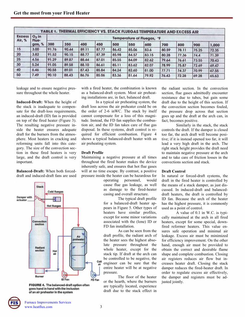
with a fired heater, the combination is known
as a balanced-draft system. Most air preheat-
ing installations are, in fact, balanced draft.
In a typical air preheating system, the
draft loss across the air preheater could be on
the order of 2-6 inWC. The stack by itself
cannot compensate for a loss of this magni-
tude. Instead, the FD fan supplies the combus-
tion air, and the ID fan takes care of flue gas
disposal. In these systems, draft control is re-
quired for efficient combustion. Figure 4
shows a typical balanced-draft heater with an
air preheating system.
Draft Profile
Maintaining a negative pressure at all times
throughout the fired heater makes the device
inherently safe, and ensures that hot flue gases
will at no time escape. By contrast, a positive
pressure inside the heater can be hazardous for
operating personnel, would
cause flue gas leakage, as well
as damage to the fired-heater
casing and overall structure.
The typical draft profile
for a balanced-draft heater ap-
pears in Figure 5. Other types of
heaters have similar profiles,
except for some minor variations
associated with the (lone) ID or
FD fan installation.
As can be seen from the
draft profile, the radiant arch of
the heater sees the highest abso-
lute pressure throughout the
whole heater, except for the
stack tip. If draft at the arch can
be controlled to be negative, the
engineer can be sure that the
entire heater will be at negative
pressure.
The floor of the heater
or the hearth, where the burners
are typically located, experience
draft due to the stack effect in
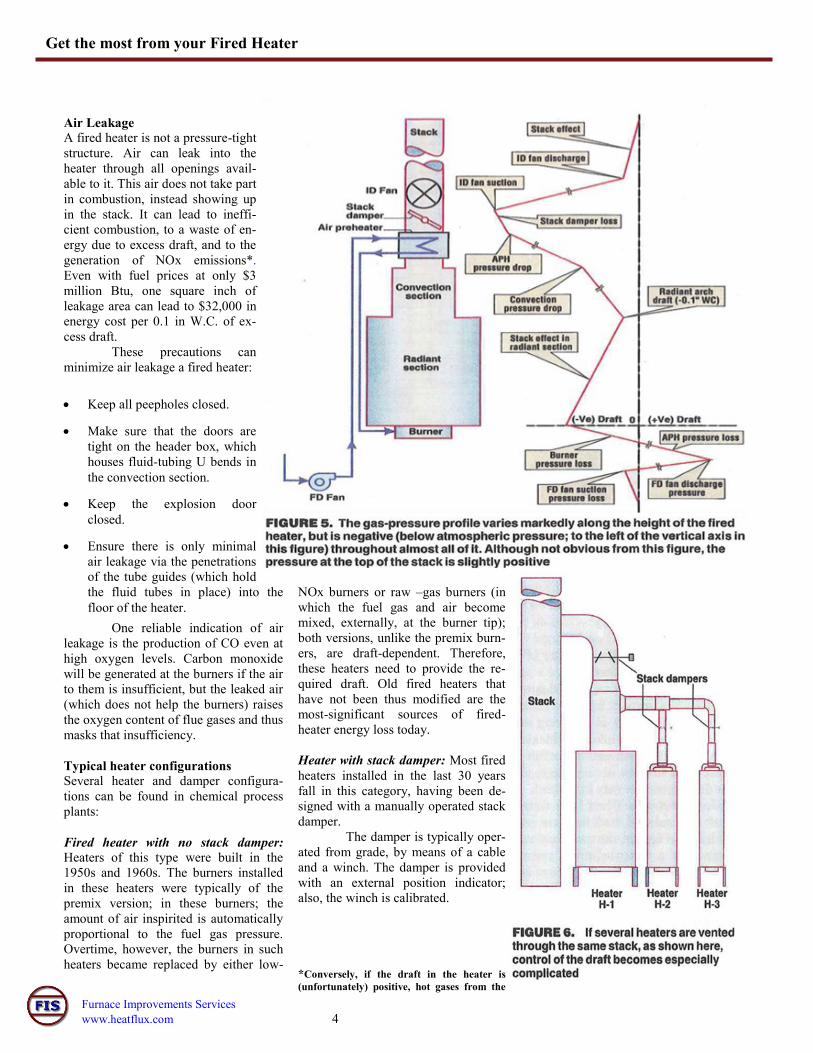
Furnace Improvements Services
www.heatflux.com 4
Get the most from your Fired Heater
NOx burners or raw –gas burners (in
which the fuel gas and air become
mixed, externally, at the burner tip);
both versions, unlike the premix burn-
ers, are draft-dependent. Therefore,
these heaters need to provide the re-
quired draft. Old fired heaters that
have not been thus modified are the
most-significant sources of fired-
heater energy loss today.
Heater with stack damper: Most fired
heaters installed in the last 30 years
fall in this category, having been de-
signed with a manually operated stack
damper.
The damper is typically oper-
ated from grade, by means of a cable
and a winch. The damper is provided
with an external position indicator;
also, the winch is calibrated.
*Conversely, if the draft in the heater is
(unfortunately) positive, hot gases from the
Air Leakage
A fired heater is not a pressure-tight
structure. Air can leak into the
heater through all openings avail-
able to it. This air does not take part
in combustion, instead showing up
in the stack. It can lead to ineffi-
cient combustion, to a waste of en-
ergy due to excess draft, and to the
generation of NOx emissions*.
Even with fuel prices at only $3
million Btu, one square inch of
leakage area can lead to $32,000 in
energy cost per 0.1 in W.C. of ex-
cess draft.
These precautions can
minimize air leakage a fired heater:
Keep all peepholes closed.
Make sure that the doors are
tight on the header box, which
houses fluid-tubing U bends in
the convection section.
Keep the explosion door
closed.
Ensure there is only minimal
air leakage via the penetrations
of the tube guides (which hold
the fluid tubes in place) into the
floor of the heater.
One reliable indication of air
leakage is the production of CO even at
high oxygen levels. Carbon monoxide
will be generated at the burners if the air
to them is insufficient, but the leaked air
(which does not help the burners) raises
the oxygen content of flue gases and thus
masks that insufficiency.
Typical heater configurations
Several heater and damper configura-
tions can be found in chemical process
plants:
Fired heater with no stack damper:
Heaters of this type were built in the
1950s and 1960s. The burners installed
in these heaters were typically of the
premix version; in these burners; the
amount of air inspirited is automatically
proportional to the fuel gas pressure.
Overtime, however, the burners in such
heaters became replaced by either low-
Furnace Improvements Services
www.heatflux.com 5
Get the most from your Fired Heater
firebox can leak out through the openings, which
poses a safety hazard.
However, dampers of this type are of poor
quality; they often get stuck, and sometime
remain fully open. Operators tend to be
reluctant to touch them so as to make ad-
justment to drafts. These dampers should
be replaced with more-reliable versions,
whether manually or pneumatic operated,
from grade or at a control panel.
Heaters with off-take dampers: A number
of cabin-type fired heaters with long con-
vection sections are equipped with single
or multiple off-take ducts, which connect
the convection sections to the stack. In
some such heaters, the dampers are in-
stalled in the off-takes instead of stack.
Multiple off-take dampers should be oper-
ated uniformly, as to avoid any imbalance
that could change the flue gas flow pattern
in the furnace.
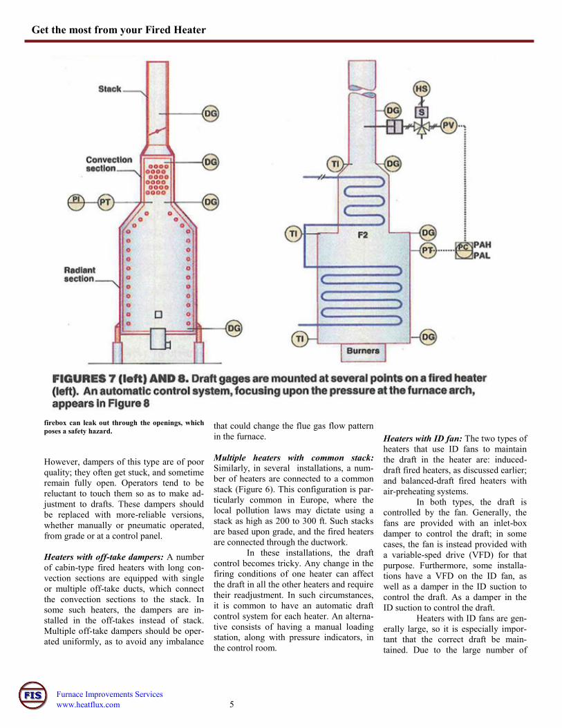
Multiple heaters with common stack:
Similarly, in several installations, a num-
ber of heaters are connected to a common
stack (Figure 6). This configuration is par-
ticularly common in Europe, where the
local pollution laws may dictate using a
stack as high as 200 to 300 ft. Such stacks
are based upon grade, and the fired heaters
are connected through the ductwork.
In these installations, the draft
control becomes tricky. Any change in the
firing conditions of one heater can affect
the draft in all the other heaters and require
their readjustment. In such circumstances,
it is common to have an automatic draft
control system for each heater. An alterna-
tive consists of having a manual loading
station, along with pressure indicators, in
the control room.
Heaters with ID fan: The two types of
heaters that use ID fans to maintain
the draft in the heater are: induced-
draft fired heaters, as discussed earlier;
and balanced-draft fired heaters with
air-preheating systems.
In both types, the draft is
controlled by the fan. Generally, the
fans are provided with an inlet-box
damper to control the draft; in some
cases, the fan is instead provided with
a variable-sped drive (VFD) for that
purpose. Furthermore, some installa-
tions have a VFD on the ID fan, as
well as a damper in the ID suction to
control the draft. As a damper in the
ID suction to control the draft.
Heaters with ID fans are gen-
erally large, so it is especially impor-
tant that the correct draft be main-
tained. Due to the large number of
Furnace Improvements Services
www.heatflux.com 6
Edited by Nicholas P. Chopey The Author Ashutosh Garg is a senior Thermal Engineer at Furnace Improvements (Sugar Land, Texas; Tel 281-980-
0325; Fax: 832-886-1665; email: [email protected]). He has almost 30 years of experience in design,
engineering, and troubleshooting of fired heaters and combustion systems. He began his career as a gradu-
ate engineer in an ammonia plant; this work was followed by six years in KTI India and eight years at EIL,
New Delhi, in the latter firm’s heater group. For the past seven years, he has been with Furnace Improve-
ments, where he provides services to the petroleum refining and petrochemical industries related to fired heat-
ers and NOx emissions reduction. He has published several papers on those two topics in trade magazines. A
registered professional engineer and a member of AIChE, he is a member of API subcommittee on heat transfer. He holds de-
gree in chemical engineering from Indian Institute of Technology, Kanpur, India.
burners and peepholes in large heaters,
high draft can readily affect the opera-
tion adversely.
Draft Control
Controlling draft requires the following
instruments and hardware:
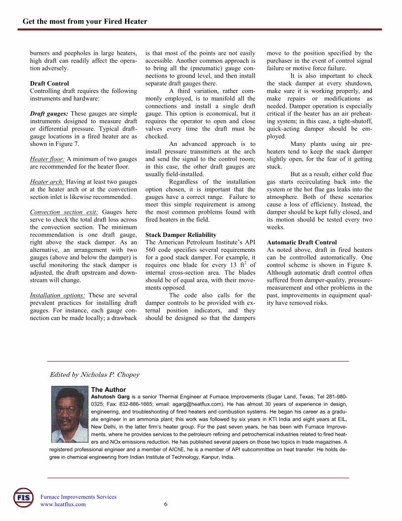
Draft gauges: These gauges are simple
instruments designed to measure draft
or differential pressure. Typical draft-
gauge locations in a fired heater are as
shown in Figure 7.
Heater floor: A minimum of two gauges
are recommended for the heater floor.
Heater arch: Having at least two gauges
at the heater arch or at the convection
section inlet is likewise recommended.
Convection section exit: Gauges here
serve to check the total draft loss across
the convection section. The minimum
recommendation is one draft gauge,
right above the stack damper. As an
alternative, an arrangement with two
gauges (above and below the damper) is
useful monitoring the stack damper is
adjusted, the draft upstream and down-
stream will change.
Installation options: These are several
prevalent practices for installing draft
gauges. For instance, each gauge con-
nection can be made locally; a drawback
is that most of the points are not easily
accessible. Another common approach is
to bring all the (pneumatic) gauge con-
nections to ground level, and then install
separate draft gauges there.
A third variation, rather com-
monly employed, is to manifold all the
connections and install a single draft
gauge. This option is economical, but it
requires the operator to open and close
valves every time the draft must be
checked.
An advanced approach is to
install pressure transmitters at the arch
and send the signal to the control room;
in this case, the other draft gauges are
usually field-installed.
Regardless of the installation
option chosen, it is important that the
gauges have a correct range. Failure to
meet this simple requirement is among
the most common problems found with
fired heaters in the field.
Stack Damper Reliability
The American Petroleum Institute’s API
560 code specifies several requirements
for a good stack damper. For example, it
requires one blade for every 13 ft2 of
internal cross-section area. The blades
should be of equal area, with their move-
ments opposed.
The code also calls for the
damper controls to be provided with ex-
ternal position indicators, and they
should be designed so that the dampers
move to the position specified by the
purchaser in the event of control signal
failure or motive force failure.
It is also important to check
the stack damper at every shutdown,
make sure it is working properly, and
make repairs or modifications as
needed. Damper operation is especially
critical if the heater has an air preheat-
ing system; in this case, a tight-shutoff,
quick-acting damper should be em-
ployed.
Many plants using air pre-
heaters tend to keep the stack damper
slightly open, for the fear of it getting
stuck.
But as a result, either cold flue
gas starts recirculating back into the
system or the hot flue gas leaks into the
atmosphere. Both of these scenarios
cause a loss of efficiency. Instead, the
damper should be kept fully closed, and
its motion should be tested every two
weeks.
Automatic Draft Control
As noted above, draft in fired heaters
can be controlled automatically. One
control scheme is shown in Figure 8.
Although automatic draft control often
suffered from damper-quality, pressure-
measurement and other problems in the
past, improvements in equipment qual-
ity have removed risks.
Get the most from your Fired Heater