Embed Size (px)
Citation preview

System FABA 100Table of Contents
Paul Vahle GmbH & Co. KGWesticker Str. 52 • D-59174 Kamen www.vahle.de
+49 (0) 23 07/ 7 04-0 +49 (0) 23 07/ 7 04-4 44
Seite 1Status 01/2005
Table of contents FABA 100
General Information ....................................................................................1 Introduction 2
Basic description 2 Typical applications 2
Conductor Rail System FABA 100 for mobile equipment 3 Technical data 3
General remarks on planning 4 A. Track Layout 4 B. Environment 4 C. Manual Operation 4 D. Electrical Transmission of Power 5 E. Data Transfer 6 F. Component information 6 G. General Installation Instructions 6
Basic Diagram 7
Standard Components ................................................................................1 Conductor-Rail 2 Conductor Rail with Hard PVC Insulation 2 Conductor Rail with Halogenfree Insulation 2
Technical Information 3 Planning Instructions 3 Installation Instructions 3
Rail-Connectors (plug-in type) 4 Technical Information 4 Planning Instructions 4 Installation Instructions 4
Rail-Connectors (screw-type) 5 Technical Information 5 Planning Instructions 5 Installation Instructions 5
Hanger-Clamp screw-type assembly 6 Technical Information 7 Planning Instructions 7 Installation Instructions 7
Power-Feeds 8 Technical Information 9 Planning Instructions 9 Installation Instructions 9
Expansion 10 General 10
Fixed Point 11 Technical Information 11 Planning Instructions 11

System FABA 100Table of Contents
Paul Vahle GmbH & Co. KG Westicker Str. 52 • D-59174 Kamenwww.vahle.de
+49 (0) 23 07/ 7 04-0 +49 (0) 23 07/ 7 04-4 44
Seite 2Status 01/2005
Installation Instructions 11 Expansion connector 12
Technical Information 12 Planning Information 13 Assembly Instructions 13
Expansion-Rail 14 Technical Information : 14
Expansion-Rail - Continuation - 15 Planning Instructions 15 Installation Instructions 15
Electrical-Separation 16 Technical Information 17 Planning Instructions 17 Installation Instructions 17
Transfer-Caps 18 Technical Information 19 Planning Instructions 19
Current Collector EAS-L Spring Pressure approx. 4 N 20 Standard Type 20 For Data Transfer 20 Technical Information 21 Planning Instructions 21 Installation Instructions 21
Current Collector EAS-K Spring Pressure approx. 2,5 N 22 Technical Information 22 Planning Instructions 22 Installation Instructions 22
Cleaning-Collector EAS-R Spring Pressure approx. 4 N 23 Technical Information 23 Planning Instructions 23 Installation Instructions 23
Base-Plate for current-collector EAS-L / EAS-K 24 Technical Information 24 Planning Instructions 24 Installation Instructions 24
Current Collector PAS-K Spring Pressure approx. 4 N 25 Current Collector PAS-L Spring Pressure approx. 6 N 25
Technical Information 28 Planning Instructions 28 Installation Instructions 28
Current collector PA DS-20 Spring Pressure approx. 7 N 29 Technical information 30 Planning instructions 30 Installation instructions 30
Tandem Collector DE AS-20 Spring Pressure approx. 2 x 4 N 31 Technical Information 32 Planning Instructions 32 Installation Instructions 32

System FABA 100Table of Contents
Paul Vahle GmbH & Co. KG Westicker Str. 52 • D-59174 Kamenwww.vahle.de
+49 (0) 23 07/ 7 04-0 +49 (0) 23 07/ 7 04-4 44
Seite 3Status 01/2005
FABA 30 Conductor Rail.............................................................................1 Conductor Rail 4
Technical Information 4 Planning Information 4 Assembly Instructions 4
Rail Connector 5 Technical Information 5 Planning Information 5 Assembly Instructions 5
Hanger Clamp 6 Power feeds 7
Technical information 7 Planning instructions 7 Installation instructions 7
Expansion – General information 8 Expansion rail for building expansion 9
Planning instructions 10 Installation instructions 10
Electrical separation 11 Technical information 12 Planning instructions 12 Installation instructions 12
Mechanical separation 13 Technical information 14 Planning instructions 14 Installation instructions 14 Technical Information 16 Planning instructions 16 Installation instructions 16
Mechanical separation multiple-pole, 45° 17 Technical information 17 Planning instructions 17 Installation instructions 17
Mechanical separation Pick up guide 18 Technical information 18 Planning instructions 18 Installation instructions 18
Current collectors 19
Data Transfer ...............................................................................................1 Introduction 2 General 3 Location of the Conductor rail system 3 Selection of Components 4

System FABA 100Table of Contents
Paul Vahle GmbH & Co. KG Westicker Str. 52 • D-59174 Kamenwww.vahle.de
+49 (0) 23 07/ 7 04-0 +49 (0) 23 07/ 7 04-4 44
Seite 4Status 01/2005
Hanger Clamps ............................................................................................1 General 2
Technical Information 2 Planning Instructions 2 Installation Instructions 2
Hanger-Clamp screw-type assembly 3 Technical Information 3
Hanger - Clamp Clip-type - Assembly height 27 mm 4 Technical Information 4
Hanger - Clamp Clip-type - Assembly height 32 mm 5 Technical Information 5
Hanger - Clamp Clip-type - Assembly height 40 mm 6 Technical Information 6
Hanger – clamp Stud – mounting with spring clip 7 Fastening-Consoles 8
Checking Devices........................................................................................1 Introduction 2 Collector shoe wearing tester 3
Working mode 3 Technical information 4 Planning instructions 4 Installation instructions 4 Maintenance 4
Dust Removal ..............................................................................................1 Introduction 2 Vaccuum and accessories 3 Vacuum and accessories - Continuation – 4
Procedure 4 Technical Information 4 Planning Instructions 5 Installation Instructions 5
Transfer Sections ........................................................................................1 Mechanical Separations For Individual Selection 3 Conductor-Rail-Transfer Complete 4
Technical Information 5 Planning Instructions 5 Installation Instructions 5
Conductor-Rail-Transfer 6 Technical Information 7 Planning Instructions 7 Installation Instructions 7

System FABA 100Table of Contents
Paul Vahle GmbH & Co. KG Westicker Str. 52 • D-59174 Kamenwww.vahle.de
+49 (0) 23 07/ 7 04-0 +49 (0) 23 07/ 7 04-4 44
Seite 5Status 01/2005
Conductor Rail Transfer 8 Technical Information 9 Planning Instructions 9 Installation Instructions 9
Conductor-Rail-Separations pick-up guide for current collectors 10 Technical Information 10 Planning Instructions 10 Installation Instructions 11
Pre-assembled System ...............................................................................1 Introduction 2 Conductor rail 3
Technical information 4 Diagram 5
Planning instructions 6 Installation instructions 6
Maintenance Manual FABA 100 .................................................................1 Cleaning instructions for FABA 100 conductor rails 3
Discontinued Components.........................................................................1
System FABA 100General Information
Paul Vahle GmbH & Co. KGWesticker Str. 52 • D-59174 Kamen www.vahle.de
+49 (0) 23 07/ 7 04-0 +49 (0) 23 07/ 7 04-4 44
Seite 1Status 01/2005
General Information
FABA-Conductor-Rail-Systems System FABA 100
for mobile equipment

System FABA 100General Information
Paul Vahle GmbH & Co. KG Westicker Str. 52 • D-59174 Kamenwww.vahle.de
+49 (0) 23 07/ 7 04-0 +49 (0) 23 07/ 7 04-4 44
Seite 2Status 01/2005
Conductor Rail System FABA 100 for mobile equipment Introduction During the last years this system has been employed under the most diverse conditions. In the performance of the various requirements on the system a multitude of components resulted which today we offer as standard. All required technical data as well as necessary notes on the planning and installation theses are shown in the following lists. Since we do not produce factory-completed equipment (such as machines) but individual components which are assembled on site for the FABA 100 Insulated Conductor Rail System much care has to be taken when the installation is very extensive or special requirements have to be observed. Please remember that for the selection and determination or ordering system components not every question on the list can be answered and hence, some experience is required; hence we suggest you plan or perform the installation with our assistance or have it done by us. We look for and find for you the optimum, especially a dependable solution valid to existing regulations. The generally accepted technical rules are to be observed during the planning, the erection and during the operation. The components of the FABA 100 system correspond with the DIN standards and VDE regulations and are to be employed and used accordingly. Basic description 1.
2. 3. 4. 5.
6. 7. 8.
9.
10. 11. 12.
13.
14.
Reliable and proven electric power-, control command- and data transfer. Permissible continuous current (at 100% DC) for FABA 40 = 40 Ampere for FABA 100 = 100 Ampere Permissible operating voltage up to 1000 V. Permissible travelling speed up to 400 m/min. For continuous ambient temperatures from – 30°C to + 55°C for the standard insulation, - 30°C to + 80°C for the heat-resistant insulation. Installation in dry interior spaces; with additional measures in damp, wet interior spaces and outdoors. IP 2x = protection against accidental contact with all live (potential carrying) parts. For potential above 50 V alternating- or 120 V direct current the system is to be installed outside the manual area. The number of poles are unlimited . Possible arrangement of the conductor surface down or sideways. The rail centre distance is 15 mm. The single current collectors for permissible continuous currents up to 50 A are fastened to the mobile equipment. As is usual for example for the electric monorail (AMS), computer-aided data may be transferred simultaneously and reliably to several mobile carriers via the conductor rails. The FABA 100 system is, by experience, extremely low in maintenance.
Typical applications Electric monorails • Light girder cranes, longitudinal- and traversing travel • shelve systems • machine tools, automated assembly lines • devices, robots moving - of course also three-dimensionally - through extended and / or work areas very rapidly • Slip rings with arbitrary number of poles, from a diameter of 400 mm.
For all operating equipment data transfer may be carried out flawlessly during standstill as well as for travelling speeds up to 20 m/sec and that during unidirectional traffic as well as during reversing traffic. Please refer to list IS 100 D for this.
The system may of course also be used under different conditions, if however, special measures or
changes are required. Please talk to us if you require our assistance. Expert field agents will be glad to assist you. You will meet a knowledgeable partner with many years of experience.
FABA – a product of VAHLE

System FABA 100General Information
Paul Vahle GmbH & Co. KG Westicker Str. 52 • D-59174 Kamenwww.vahle.de
+49 (0) 23 07/ 7 04-0 +49 (0) 23 07/ 7 04-4 44
Seite 3Status 01/2005
Conductor Rail System FABA 100 for mobile equipment
Technical data FABA 40 FABA 100 Metal rail a) Cross - section a) 24 mm² a) 24 mm² b) Material b) Steel, galvanised b) copper Permissible cont. current :
a) Standard-Isul. Up to 35°C amb. Temp. a) 40 Ampere a) 100 Ampere
(100 % Duty cycle) b) Heat resistent-Isul. Up to 55°C amb. temp. b) 40 Ampere b) 100 Ampere
Resistance of a) For altern. current (50 Hz), impedance a) Z = 0,00532 Ohm/m a) Z = 0,00078 Ohm/m metal rails 15 mm centre distance at amb. Temps. b) For direct current b) R = 0,00493 Ohm/m b) R = 0,00077 Ohm/m up to 35°C :
Coefficient of linear expansion for the conductor rail α = 12 ⋅ 10 -6 [K-1] α = 17 ⋅ 10 -6 [K-1]
Conductor rail : a) Number of poles a) from 1 till ∞, i.e. arbitrarily selected b) length b) 3 m and 5 m c) Hanger distance c) In straight sections max. 0,8 m, in bends max. 0,4 m d) Centre distance min d) 15 mm e) Bending radius = possible „on site“ e) min 500 mm, in all directions
Insulating sleeve a) Colour for standard insulation a) Current conductor rails orange, ground conductor rails yellow with continuous green stripe b) Colour for heat resistant insulation b) Current conductor rails black, ground conductor rails green with continuous yellow stripe c) Same lengths as metal rail c) Easy shortening "on the site" possible d) materiel d) Standard design: hard PVC Heat resistant design: heat resistant hard PVC e) Combustibility e) Flame-resistant, self-extinguishing
Current collector: a) Number of poles a) from 1 to multi-poles arbitrarily selected b) System b) Individual design (each "operates" on its own) c) For each conductor rail,
(current- / data- / ground-) c) Basically only 1 current collector required
d) Permissible continuous current (at 100 %)
d) One-arm design = 16 c.e.. 20 Ampere
at 35°C amb. Temp. Parallel-arm-design = 20, 30, 40, 50 Ampere e) Fastening to the operating equipment e) All neighbouring collectors attachable in series f) Operating area f) One-arm design, stroke ± 15, swivel ± 20 mm One arm small, stroke ± 8, swivel ± 8 mm Parallel-arm, stroke ± 15, swivel ± 20 mm Parallel-long-arm, stroke ± 30, swivel ± 50 mm g) Collector shoe g) The length of the collector shoe bridges switch- junctions, expansion points and similar separations h) Collector shoe, material h) Copper graphite silver containing carbon for data transfer
For the a) Permissible operating voltage a) Up to 1000 V complete b) Travelling speed b) Up to 400 m/min (on occasion even more) system c) Application c) Indoors/outdoors with additional cover d) Arrangement of the rail conductor surface d) Selectively down or sideways e) Protection against accidental contact e) IP 2x With live parts f) Permissible continuous ambient temperature f) - 30 °C to + 55 °C for standard insulation - 30 °C to + 80 °C for heat-resistant insulation g) Expansion points g) Yes; at arbitrary locations by caps h) Electrical separation points h) Yes; at arbitrary locations by caps k) Mechanical separation k) Yes, with caps on switches; Pick up guides for extended separations for parallel-arm conductors l) Chemical resistively l) Largely resistant against gasoline, oils dilute bases and dilute acids m) Combustibility (insulation casing, refer there) m UL 94 V-O
The data refer to our usual listed component parts (unless specified differently).
For special requests - please contact us !

System FABA 100General Information
Paul Vahle GmbH & Co. KG Westicker Str. 52 • D-59174 Kamenwww.vahle.de
+49 (0) 23 07/ 7 04-0 +49 (0) 23 07/ 7 04-4 44
Seite 4Status 01/2005
Conductor Rail System FABA 100 for mobile equipment
General remarks on planning
* Plan and construct the installation in such a way as to avoid dangerous situations. * Appropriate counter measures have to be instituted if wrong-doings of personnel is to be expected.
A. Track Layout 1. For the desired compact installation of the system, special attention is to be paid that the conductor rails are installed
in a way as not to impede the free movement of the current collectors moving through the complete installation - including bends etc. - ; please refer to : "Operating Range of the Current Collector".
2. Basically the system is suitable for a back and forth operation.
Special precautions do not have to be taken. 3. Very careful planning and installation is a prerequisite for travelling speeds above 400 m/min . 4. Radii of more than 0.5 m for conductor rails are possible in all directions, hence, horizontal-, vertical bends and
inclines can be realised. Rails with radii of less than 0.5 m can only be bent at the factory, please consult us. 5. Mechanical interruptions of the conductor rails with transfer caps e.g. for pivot- and sliding switches, shunting stages,
hoist stations have to be installed correctly, so that the permissible displacement of the opposing caps - also while loading just one end of the switch - is not exceeded.
B. Environment 1. In dry interior spaces the system can be employed without restrictions. 2. a) In damp areas Conductor Rail centers are to be 30 mm and installed hanger clamp height 40 mm to prevent
current creapage. b) In dry interior spaces dripping water has to be deflected by covers. c) In areas where water jets are in operation, the rails are to be installed as stated under a); they may only
be sprayed when turned off. 3. For outdoor installations the rails are to be installed as described in section 2. a), with an additional cover. 4. Do not employ in areas of explosion hazard. 5. Conductor rails which are planned for areas where external mechanical demands (e.g. use of ladders) are to be
expected have to be provided with covers (at least in part). 6. On danger of external heavy showers of sparks (welding- or grinding sparks) covers are to be installed in this area. 7. Please consult us if the conductor rail system is to be exposed to extreme chemical influences. 8. The system cannot be heated.
C. Manual Operation 1. Without limitations for operating voltages up to 60 V alternating- or 120 V direct current. 2. Beyond that: a) Without limitations in electrical/locked electrical operating locations. b) In general operating locations the personnel have to be protected by screening at a suitable distance.
Safety distance/manual operation is 2.5 m in height and 1.25 m to the side measured from the floor. c) Additional measures have to be taken if there is danger of touching the live conductor surface with thin,
conducting objects (e.g. ends of wires). 3. Please contact us for the transmission of voltages above 1000 V. 4. Final temperatures up to 75°C may develop for the standard insulation or of up to 100°C for the heat-resistant
insulation.

System FABA 100General Information
Paul Vahle GmbH & Co. KG Westicker Str. 52 • D-59174 Kamenwww.vahle.de
+49 (0) 23 07/ 7 04-0 +49 (0) 23 07/ 7 04-4 44
Seite 5Status 01/2005
D. Electrical Transmission of Power Since the system is employed for varying purposes, we restrict ourselves to general, however
important facts which should be considered. 1. Current capacity of the conductor rails - refer to Table 1 :
In determining the total current - i.e. all users - the following is to be considered : a) How often or at which points is the system to be supplied ? b) How are the users (or is the user) utilised, or how large is the duty cycle (DC) ? c) How high is the expected maximum ambient temperature ?
Table 1 = Conductor rails permissible continuous current [A] for 100 % Duty cycle for continuous ambient temperature up to [°C] Insulation 35 40 45 50 55 60 65 70 75 80 FABA 40 Standard 40 36 32 28 24 -- -- -- -- -- steel Heat-resistant 40 40 40 40 40 35 30 25 20 15 FABA 100 Standard 100 90 80 70 60 -- -- -- -- -- copper Heat-resistant 100 100 100 100 100 90 80 70 60 50
2. Potential drop : a) The potential drop for conductor rails is in general not to be more than 3 %. b) It is to be considered how often or at which points the system is to be supplied. c) The resistance of the conductor rails increases with higher ambient temperatures - refer to table 2.
We have listed the most unfavourable values; they were determined under continuous currents of 40 A for FABA 40 and 100 A for FABA 100.
Table 2 = Conductor rails Resistance [Ohm/km] for continuous ambient temp. up to [°C] for 35 40 50 60 70 80 Altern. current (impedance); 50 Hz; FABA 40 15 mm center separation 5.32 5.48 5.85 6.25 6.73 7.28 Direct current 4.93 5.08 5.38 5.80 6.24 6.75 Altern. current (impedance); 50 Hz; FABA 100 15 mm center separation 0.78 0.83 0.95 1.05 1.18 1.34 Direct current 0.77 0.82 0.94 1.04 1.16 1.32
3. Conductor rail for the ground conductor : a) Whether and when the ground conductor rail is employed is to be determined for the individual installation -
e.g. users with small protective voltage? User protectively insulated? b) Consider the ambient temperature possibly developing; standard- or heat-resistant insulation ? c) Do not use ground conductor rails for control purposes. d) Arrangement may be carried out individually. We suggest to locate it in the front if there is danger of contact. 4. Current capacity of the current collectors - refer to table 3 : a) The ambient temperature has to be considered. b) In principle only one current collector is required per conductor rail for the transmission of power.
Table 3 = Current collector Permissible continuous current [A] for 100 % Duty cycle for continuous ambient temp. up to [°C] 35 40 50 60 70 80
One-arm current collector 20 20 16 12 8 4 small; with cable 0,75 mm² 10 10 8 6 4 2 with cable 1,5 mm² 16 16 12 9 6 3 Parallel-arm collector with cable..........1,5 mm² 20 20 16 12 8 4 2,5 mm² 30 30 25 20 15 10 4,0 mm² 40 40 33 26 20 14 6,0 mm² 50 50 42 34 26 18 Parallel-arm collector, long arm 1,5 mm² 20 20 16 12 8 4 with cable 2,5 mm² 30 30 25 20 15 10 4,0 mm² 40 40 33 26 20 14 6,0 mm² 50 50 42 34 26 18 5. Current collector for the ground conductor : As for the transmission of power, only one current collector is required for the ground conductor rail.

System FABA 100General Information
Paul Vahle GmbH & Co. KG Westicker Str. 52 • D-59174 Kamenwww.vahle.de
+49 (0) 23 07/ 7 04-0 +49 (0) 23 07/ 7 04-4 44
Seite 6Status 01/2005
Conductor Rail System FABA 100 for mobile equipment
General remarks on planning - Continuation
E. Data Transfer 1. Please consider the special list IS 100 D "Data Transfer" with its detailed information. 2. For simple tasks, e.g. to trigger control commands, electric or isolation separations are arranged in additional
conductor rails; use current collectors with copper-carbon. 3. For the computer-aided data transfer additional conductor rails (and only those of copper) and current collectors with
silver-carbon - for this case perhaps two current collectors per rail - are to be planned for. 4. We suggest to make use of our assistance when needed.
F. Component information 1. Conductor rails : a) Arrangement of the collector surface down or sideways. b) Arbitrary number of poles possible. c) Minimum and usual rail center separation of 15 mm. d) Hanger- or support separation for straight sections of max. 0.8 m, in radii/bends of max. 0.4 m 2. Hanger clamps : a) One-pole for rail center separations of 15 mm or larger. b) Multi-pole for rail center separations of 15 mm. Important! Pay attention to the assembly height, choice 27, 32, 40 mm. The construction height remains the
same even for further components in the complete installation and is of importance if the system is to be fastened to continuous webs - such as for electric monorails for example - .
3. Feeds : a) Power feeds of up to 100 A are possible at each conductor rail joint, a single-core feed cable is required. b) Furthermore it is possible to feed (also for control currents, data transfer and similar) at separation points such as
switch transfer locations etc. and also at the beginning or the end of a system: 4. Expansions : a) Only centered fix points are to be arranged for linear systems of up to 60 m where the end caps can expand. For
changes in length of the conductor rail (caused by fluctuations of the ambient temperature and / or current heating) the conductor rails slide in their hanger clamps.
b) Expansion points are to be provided for installations longer than 25 m and in the straight stretches and between bends where both ends are fixed firm e.g. through switches lifts etc.
5. Separation points : a) Electric separations of the conductor rails can be provided at practically every point of the system, e.g. at repair
stretches; they may serve to trigger control pulses. The separation points or separation caps may be provided with connecting cables depending on the requirement.
b) Mechanical separations are required for switches and lift sections. They are installed by affixing transfer caps which are available in one-pole and multi-pole design. The power feed is possible on these caps.:
c) The separation points are installed so that they may be bridged by one collector shoe, i.e. usually only one current collector is required per conductor rail, however, the instructions on the components are to be observed.
d) Pick up guides are available for large conductor rail separations. Because these are not in daily use please observe the special list IS 100 U.
G. General Installation Instructions 1. No special tools are required for simple installations in straight sections. 2. For branched stretches - typical for the electric monorail -, or for extended installations it is certainly helpful to use the
tools shown in the list of accessories or tools, i.e. they are to a large extent of vital importance. 3. First mark all conductor rail hanger locations and install the hanger clamps in a well aligned manner. 4. Start the further installation in the area of switches, hoist stations, lift sections and bends; these have to be definitely
carefully pre-aligned 5. Inspection at the end of the installation : • Are conductor rails correctly engaged in the hanger clamps ? • Do both sides of all housings (joint / feed) and all caps embrace the insulating sheath of the conductor rails? • Are all screws and bolts securely tightened, e.g. rail connectors to be screwed? • Have all burrs been removed on the contact surface ? • Are all cables connected? • Are the transfers at mechanical separation points - such as switches - in operating order? • Is the expansion gap correctly adjusted? Fixed points installed ?

System FABA 100General Information
Paul Vahle GmbH & Co. KG Westicker Str. 52 • D-59174 Kamenwww.vahle.de
+49 (0) 23 07/ 7 04-0 +49 (0) 23 07/ 7 04-4 44
Seite 7Status 01/2005
Basic Diagram
Measurement a Hanger clamp distance : max. 800 mm in straight sections and 400 mm in bends.
Separation of support clamps; adhered to on at least one side as follows : Measurement b For the rail connector of the conductor rail : min. least 100 mm; max. 200 mm. Measurement c For the feed : min. 100 mm; max. 200 mm. Measurement d For the expansion : min. 100 mm; max. 200 mm. Measurement e For separations with separation caps : min. 100 mm; max. 200 mm supported both sides. Measurement f For the separation with transfer caps : min. 50 mm; max. 100 mm.
Please refer to the special list IS 100 U for this. Measurement g
Height of system = upper edge of hanger clamp to lower edge of current collector fastening : Note : Assembly height is the height of the hanger clamp.
with standard collector with standard small collector for assembly height 27 = 73 mm; for assembly height 27 = 71 mm; for assembly height 32 = 78 mm; for assembly height 32 = 76 mm; for assembly height 40 = 86 mm for assembly height 40 = 84 mm with double arm collector with long double arm collector with double shoe collector for assembly height 27 = 98 mm; for assembly height 27 = 108 mm; for assembly height 27 = 98 mm; for assembly height 32 = 103 mm; for assembly height 32 = 113 mm; for assembly height 32 = 103 mm; for assembly height 40 = 111 mm for assembly height 40 = 121 mm for assembly height 40 = 111 mm

System FABA 100General Information
Paul Vahle GmbH & Co. KG Westicker Str. 52 • D-59174 Kamenwww.vahle.de
+49 (0) 23 07/ 7 04-0 +49 (0) 23 07/ 7 04-4 44
Seite 8Status 01/2005
FABA – a product of VAHLE A Conductor Rail FABA 40 for 40 A, FABA 100 for 100 A; both types are of equal dimensions; 3 m or 5 m long; Collector arrangement
selectively facing down or sideways; unlimited number of poles possible; radii from 0.5 m; under 0.5 m only bent at the factory; simple installation by clipping into the hanger clamp.
B Rail Splice Connector Screw-type or plug-in type for quick installation. C HANGER CLAMP Determine the construction height according to your local conditions, selectively 27 or 32 or 40 mm. Use only : 32 mm or 40 mm for crane installations, for mounting to consoles for example.
27 mm only for small mounting Systems (EHB); Construction : Use a 1-pole hanger clamp 32 mm height for rail centres for more than 15 mm.
Use a multi pole hanger for 15 mm centres. Hanger clamps to be screwed are shown in this list. Further designs are found in the supplementary
list IS 100 K, those that directly clip onto the electric monorail tracks for example. D POWER FEED Up to 50 A etc. 100 A at the conductor rail joint; use a single-core connection cable. E EXPANSION Shown is the "expansion bridge" design: an air gap remains between the ends of the conductor rails, i.e.
a change in length of the conductor rails of up to 25 mm (caused by heat / cold) can be compensated here. A fixed point is to be installed between two expansion points.
F SEPARATION WITH SEPARATION CAPS For electrical interruption, e.g. at repair sections or to trigger control pulses; with the possibility of single-core
feed at one or both sides; Remark: An air gap remains between the plugged-in separating caps, i.e. changes in lengths of the
conductor rails up to 10 mm can be compensated here. G Separation with transfer caps For example for switches, hoist stations with feed-in possibility.
If required consider also the special list IS 100 U with its installations with pick up guides. H CURRENT COLLECTOR Single-design: each "operates" independently; usually only one current collector is required per conductor rail;
suitable for unidirectional- and reversing operation; unrestricted travelling speed of up to 400 m/min, for robot-machines and similar, even more. the highly flexible connecting cables are one-core and are fastened to the exchangeable head or wear part.
• One-arm current collector 16 or 20 A; for a conductor rail centre separation of 15 mm; are plugged onto
one common base plate; the base plate is bolted to the equipment. • Parallel-arm current collector for 25 or 50 A; for a conductor rail centre separation of 20 mm or more;

System FABA 100Standard Components
Paul Vahle GmbH & Co. KG Westicker Str. 52 • D-59174 Kamenwww.vahle.de
+49 (0) 23 07/ 7 04-0 +49 (0) 23 07/ 7 04-4 44
Seite 1Status 01/2005
Standard Components
FABA-Conductor-Rail-Systems System FABA 100
Standard-Components
for mobile equipment

System FABA 100Standard Components
Paul Vahle GmbH & Co. KG Westicker Str. 52 • D-59174 Kamenwww.vahle.de
+49 (0) 23 07/ 7 04-0 +49 (0) 23 07/ 7 04-4 44
Seite 2Status 01/2005
Conductor-Rail
Conductor Rail with Hard PVC Insulation
Order-No. Fig. Identification Length Material Insulation hard-PVC Weight 200 009 299 3 m Standard orange 0,720 200 009 499 1 Conductor rail 5 m Metal- Standard orange 1,200
FABA 40 rail 200 010 299 3 m steel Standard PE Ground yellow with green stripe 0,720 200 010 499 5 m galvanised Standard PE Ground yellow with green stripe 1,200
201 009 299 3 m Standard orange 0,805 201 009 499 1 Conductor-rail 5 m Metal- Standard orange 1,340
FABA 100 rail 201 010 299 3 m copper Standard Ground yellow with green stripe 0,805 201 010 499 5 m Standard Ground yellow with green stripe 1,340
Conductor Rail with Halogenfree Insulation
Order-No. Fig. Identification Length Material Insulated halogen-free Weight
206 009 299 3 m Heat-resistant orange 0,720 206 009 499 1 Conductor rail 5 m Metal- Heat-resistant orange 1,200
FABA 40 rail 206 010 299 3 m steel Heat-resistant PE Ground yellow with green stripe 0,720 206 010 499 5 m galvanised Heat-resistant PE Ground yellow with green stripe 1,200
207 009 299 3 m Heat-resistant orange 0,805 207 009 499 1 Conductor-rail 5 m Metal- Heat-resistant orange 1,340
FABA 100 rail 207 010 299 3 m copper Heat-resistant Ground yellow with green stripe 0,805 207 010 499 5 m Heat-resistant Ground yellow with green stripe 1,340
241 000 005
2
Bending strip
1 m
Hard PVCblack
Ring material100 m
Ring material 100 m remains in rail
241 000 015 2 Bending strip 1 m Halogen free 0range
Ring material100 m
Please specify the length in your order
3,200
241 000 006 3 Bending profile 5 m PVC red Straight profile multiple use 0,250 241 045 001 4 Bending machine for manual operation 11,20
518 503 000 without Fine file 0,095 518 505 000 without Hacksaw 0,135 518 505 010 without Blades (spares; 12 Pieces) 0,038

System FABA 100Standard Components
Paul Vahle GmbH & Co. KG Westicker Str. 52 • D-59174 Kamenwww.vahle.de
+49 (0) 23 07/ 7 04-0 +49 (0) 23 07/ 7 04-4 44
Seite 3Status 01/2005
Conductor-Rail - Continuation - Technical Information • Permissible continuous current (for 100 % Duty Cycle): FABA 40 = 40 A, FABA 100 = 100 A;
for standard insulation up to an ambient temperature of 35 °C, for heat-resistant insulation up to an ambient temperature of 55 °C. For higher ambient temperatures reduce according to table 1, list IS 100 A.
• Permissible continuous ambient temperatures: from – 30°C to + 55°C for standard insulation,
from – 30°C to + 80°C for heat-resistant insulation. • Refer to table 2 of list IS 100 A for the resistance of the conductor rails also for different ambient
temperatures. • Metal rail and insulating sleeve are of equal length.
Planning Instructions • Conductor rails may be shortened "on site". • Radii are possible in all directions :
bending radii larger than 0.5 m "at the site"; bending radii from 0.2 m to 0.5 m can only be bent at the factory, please inform us if required.
• In general, the use of rail lengths of 5000 mm is standard. However where cramped physical conditions are present,
the length of 3000 mm is to be recommended for better handling. Installation Instructions a) Hanger clamp
distance : In straight runs, In bends,
max. 800 mm, max. 400 mm.
b) Shortening : With fine-toothed hacksaw, start sawing at the conductor surface.
De-burr the cuts - especially the metal conductor surface - with a fine file c) Bends :
Carried out with the bending machine with bending strips; generally "done on site", if requested at the factory. The smallest bending radius to all sides is 500 mm.
• Determine the approximate length of the curve and mark it with a felt pen on the insulating sleeve.
Mark at least 150 mm from the end of the rail (both ends of the rail cannot be bent and remain straight). • When bending over the conducting surface or the back of the rail insert the grey bending strip between the back of
the metal rail and the insulating sleeve. When using the "screw-type" rail connector and / or the separating- or transfer caps insert the strip 40 mm Shorter. After bending retract the strip by 20 mm.
• When bending over the wide side of the rail the red bending profile has to be inserted into the slit of the conductor
surface and the grey bending strip has to be inserted into the back of the rail. • Insert the rail into the bending machine until the first mark on the bend is centred over one of the lower rolls.
Tighten the upper roll depending on the required radius. Slide the rail through the machine up to the second marking. It is possible to make corrections by again passing the rail through the machine. Record the scale setting for equal bends.
• If two bent rails have to be joined, shorten the rails to be joined by the straight end
(approx. 150 mm). Use only "screw-type" rail connectors.

System FABA 100Standard Components
Paul Vahle GmbH & Co. KG Westicker Str. 52 • D-59174 Kamenwww.vahle.de
+49 (0) 23 07/ 7 04-0 +49 (0) 23 07/ 7 04-4 44
Seite 4Status 01/2005
Rail-Connectors (plug-in type)
Order No. Fig.. Identification Weight 241 002 010 1 Rail connector, plug-in one-pole; complete; packed unit, in bag 0,008
241 026 006 1 Housing Plastic-black only as spare 0,003 241 026 015 1 Plug-in connector Bronze spring-steel only as spare 0,005
241 046 020 2 Installation handle Metal end with bore of ∅ 8,5 0,135 241 046 010 3 Connecting vice 1,296
Technical Information • Permissible continuous current 100 A (for 100 % Duty Cycle). • Permissible ambient temperatures – 30 °C to + 80 °C .
Planning Instructions • Distance to the next hanger clamp: min. 100 mm; max. 200 mm. • Preferably for quick installation of extensive systems. • Do not use in bends. • The rail connector is not remountable / reusable.
Installation Instructions
If the connection of the conductor rail has to be separated, it has to be cut out – approx. 60 to 70 mm. With a fine-toothed hacksaw from the side of the conductor surface - refer to "shortening" of conductor rail.
Insert the plug connector into the installation handle.Press the plug connector to the stop into the not yet mounted conductor rail. Slide the housing onto the end of the conductor rail (over the plug connector) until the stop. Clip the rail into the already installed hanger clamps. Guide the rail to the one already installed. Slide on the housing; take care that the sides of the housing embraces both insulating sheaths! Fix the connecting vice to both sides of the joint : tighten both tongues; hold the tongue which grips the already installed rail with the left hand; using the right hand push the handle so that the conductor rails are drawn completely together (to be reversed for "left-handed" persons). Inspection : Are both insulating rims embraced by both sides of the housing? Disassembly :

System FABA 100Standard Components
Paul Vahle GmbH & Co. KG Westicker Str. 52 • D-59174 Kamenwww.vahle.de
+49 (0) 23 07/ 7 04-0 +49 (0) 23 07/ 7 04-4 44
Seite 5Status 01/2005
Rail-Connectors (screw-type)
Order-No. Fig Identification Weight 241 002 000 1 Rail connector, screw-type one-pole; complete; Packed unit, in bag 0,017
241 026 005 1 Housing Plastic-black Only as spare 0,003 251 002 000 1 Screw connector Clip with spring-steel and screw M 6 Only as spare 0,014
518 501 010 2 Screwdriver 4 mm for recessed hex-bolt 0,036
Technical Information • Permissible continuous current 100 A (for 100 % Duty Cycle). • Permissible ambient temperatures – 30 °C to + 80 °C.
Planning Instructions • Distance to the next hanger clamp: min. 100 mm; max. 200 mm. • Preferably for smaller installations. • Used also for joints of conductor rails in bends. • The rail connector is remountable / reusable several times. • A gap of 10 mm remains between the ends of the conductor rails.
Installation Instructions • Slightly loosen the screw of the screw connector with the screw driver. • Insert the screw connector
into the already installed conductor rail.
• Clip the next conductor rail into the already installed hanger clamp. • Guide the conductor rail to the joint and slide together until the stop; take care that the housing completely embraces
the insulating sleeve rims! • Tighten the screw securely using a Allen key screwdriver. • Inspection : Are both insulating sleeves embraced by both sides of the housing?
• Slide on the housing; payattention that the housing embraces the insulating sleeve rims!

System FABA 100Standard Components
Paul Vahle GmbH & Co. KG Westicker Str. 52 • D-59174 Kamenwww.vahle.de
+49 (0) 23 07/ 7 04-0 +49 (0) 23 07/ 7 04-4 44
Seite 6Status 01/2005
Hanger-Clamp screw-type assembly
Order-No. Fig. Identification Height a b Assembly weight 241 006 128 4-poles 60 30 0,015 241 006 127 5-poles 75 15 0,019 241 006 137 6-poles 90 30 0,023 241 006 126 7-poles 105 30 One piece 0,026 241 006 130 8-poles 120 15 0,030 241 006 131 1 Hanger- 9-poles 27 mm 135 30 0,034 241 006 132 clamp 10-poles 150 30 0,038 241 006 133 11-poles 165 15 Plastic-orange 0,042 241 006 134 12-poles 180 45 0,045 241 006 135 13-poles 195 45 0,049 241 006 136 14-poles 210 15 0,053
241 003 000 2 Hanger-clamp 1-polig 32 mm continues One piece; Plastic-orange 0,004
241 009 211 2-poles 30 0,006 241 009 212 3-poles 45 0,009 241 009 213 4-poles 60 0,012 241 009 214 5-poles 75 One piece; 0,015 241 009 215 6-poles 90 0,018 241 009 216 3 Hanger- 7-poles 32 mm 105 0,021 241 009 217 clamp 8-poles 120 0,024 241 009 218 9-poles 135 Plastic-orange 0,027 241 009 219 10-poles 150 0,030 241 009 220 11-poles 165 0,033 241 009 210 12-poles 180 0,036
241 009 223 4-poles 60 0,020 241 009 224 5-poles 75 One piece; 0,025 241 009 225 4 Hanger- 6-poles 40 mm 90 0,030 241 009 226 clamp 7-poles 105 Plastic-orange 0,035 241 009 227 8-poles 120 0,040
241 013 000 5 Screw set M6 x 12 For threaded hole With spring washer; Set; zinc-plated, in bag 0,005
241 013 001 6 Screw set M6 x 20 For through hole With spring washer and nut; Set; zinc-plated, in bag 0,008
241013 003 7 Screw set M6 x 25 For clamp Fig. 1 With washer orange,
spring washer and nut Set; zinc-plated, in bag
0,010
241 013 022 Screw set M6 x 12 For clamp Fig. 3 With washer, spring washer 0,008 241 013 023 8 Screw set M6 x 16 and plate with thread hole 0,009 241 013 024 Screw set M6 x 20 Set; zinc-plated, in bag 0,010
241 046 021 9 Dismantling wedge For removing rail from hanger clamps
Plastic-orange 0,014

System FABA 100Standard Components
Paul Vahle GmbH & Co. KG Westicker Str. 52 • D-59174 Kamenwww.vahle.de
+49 (0) 23 07/ 7 04-0 +49 (0) 23 07/ 7 04-4 44
Seite 7Status 01/2005
Hanger-Clamp screw-type - Continuation - Technical Information • Permissible ambient temperatures – 30°C to + 80°C. • FABA hanger clamps guarantee good sliding characteristics for the conductor rail during the expansion process. • Besides the hanger clamp shown, we manufacture other types as well, in particular clip-in types for (electric monorail
tracks), corresponding to special list IS 100 K, examples of fastening and consoles are shown there. Planning Instructions • Recommendation for
application : Construction Height
27 mm for confined installation conditions only; 32 mm for crane installations for example, for mounting to consoles; 40 mm for crane installations for example, for mounting on consoles.
• The 1-pole type is preferably used for conductor rail center separations larger than 15 mm;
for example 30 mm centers for outside application. • For multi-pole hanger clamps with an assembly height of 32 mm and above control and feed cables may be passed
through openings above. • The installation of the ground rails is possible at an arbitrary location. • Distances of hanger clamps: in straight sections max. 800 mm, in bends max. 400 mm, to the ends of the
conductor rails min. 100 mm, max. 300 mm. • The hanger clamps are screwed to the consoles, tracks or similar with M 6 screws :
the multi-pole types are to be fastened left and right, above poles at the center also. • Standard-screw-fastening material according to fig. 5 ;fig. 6,fig. 7 and fig. 8; other screw connetions on request.
Installation Instructions • Depending on the type of the installation the hanger clamps are fastened directly or by means of consoles
to the track / conductor rail; they have to be perfectly aligned. • The conductor rails are simply clipped into the hanger clamps until they snap in with a click ! • The conductor rail can be removed from the hanger clamp at any time: spread the sides of the hanger clamp;
for extensive systems we suggest the use of the dismantling wedge.

System FABA 100Standard Components
Paul Vahle GmbH & Co. KG Westicker Str. 52 • D-59174 Kamenwww.vahle.de
+49 (0) 23 07/ 7 04-0 +49 (0) 23 07/ 7 04-4 44
Seite 8Status 01/2005
Power-Feeds
Order-No. Fig. Identification Weight 241 015 000 1 Splice-feed one-pole; complete; Packing unit, in bag; 0,030
100 A for assembly height from 32 mm; for feed cable up to 16 mm²
241 015 050 2 Splice-feed one-pole; complete; Packing unit, in bag; 0,024 50 A for assembly height from 27 mm; for feed cable up to 6 mm²
241 015 090 3 End-feed one-pole; complete; Packing unit, in bag; 0,029 100 A for assembly height from 27 mm; for feed cable up to 16 mm²
241 040 045 16 mm² 10,7 outer-∅ 1000 V black Single-core 241 040 039 10 mm² 8,3 outer-∅ 1000 V black flexible cable 1 m long 241 040 026 6 mm² 6,5 outer-∅ 1000 V black One side titted with 241 040 037 4 mm² 5,3 outer-∅ 1000 V black Terminal M6; 241 040 460 4 Feed cable 2,5 mm² 4,5 outer-∅ 1000 V black 1 m long 241 040 057 16 mm² 9,2 outer-∅ Ground green-yellow (other lengths 241 040 040 10 mm² 7,9 outer-∅ Ground green-yellow on request) 241 040 051 6 mm² 6,3 outer-∅ Ground green-yellow 241 040 038 4 mm² 4,9 outer-∅ Ground green-yellow 241 040 456 2,5 mm² 3,9 outer-∅ Ground green-yellow
241 026 051 1 Assembly height 32 mm only 0,007 241 015 051 2 Housing Assembly height 27 mm Plastic-black as spare 0,006 241 014 010 3 Face closed 0,005 251 015 000 1 with asymmetric nut only 0,023 241 015 052 2 Screw clamp with square nut M 6 with recessed hex-bolt SW 4 as spare 0,018 251 022 020 3 pair of clips on one side 0,023
506 006 002 Cable shoe >1 - 2,5mm² cable For 0,001 506 006 006 5 DIN 46234 >2,5 - 6mm² cable crimping 0,002 506 006 010 E-Cu galv. >6 - 10mm² cable requirements 0,003 506 006 016 For above feeding clamps >10 - 16mm² cable 0,004
518 501 010 6 Screwdriver Allen key 4 mm For recessed hex-bolt M 6 0,036
System FABA 100Standard Components
Paul Vahle GmbH & Co. KG Westicker Str. 52 • D-59174 Kamenwww.vahle.de
+49 (0) 23 07/ 7 04-0 +49 (0) 23 07/ 7 04-4 44
Seite 9Status 01/2005
Power-Feeds - Continued – Technical Information • The permissible continuous current depends on the feed cable (and the ambient temperature) :
Splice-feed max. 100 A or 50 A; End-feed max. 100 A. • Permissible ambient temperatures – 30°C to + 80°C. • The feeds are suitable for the connection of the listed feed cables.
Planning Instructions a) Splice-feed 100 A : • Connection at the joint of the conductor rail (the rail connector is not required then). • Not to be used in bends. • Suitable for construction heights from 32 mm; for all conductor rails - also ground. Fig. 1 b) Splice-feed 50 A: • Connection at the joint of the conductor rail (the rail connector is not required then). • Not to be used in bends. • Suitable for construction heights from 27 mm; for all conductor rails - also ground. Fig. 2 c) End-feed 100 A: • Connection at the beginning and / or the end of the conductor rail installation. • Suitable for construction heights from 27 mm, for all conductor rails - also ground. Fig. 3
Installation Instructions a) Power-feed
For max. 100 A : • Loosely connect the feed cable to the screw clamp. • Insert the screw clamp into the already installed conductor rail. • Slide on the housing: take care that both sides of the insulating sheath are embraced. • Clip the next conductor rail into the support clamp and move it towards the joint; slide
together; the sides of the insulating sheath have to be embraced. • Tighten the screw well. • Be sure to Install the feed cable so that it can follow the linear expansion of the rail; for the installation through webs (e.g. electric
monorail tracks) provide grommet-protection. • For more than 50 V: provide a separation of 3 mm or surface insulation to the grounded parts. • Inspection at the end: Are both sides of both insulating sheaths embraced by the housing?
b) End-feed 100 A: • Lead the feed cable through the housing. • Loosely connect the cable lug to the screw clamp. • Plug the screw clamp into the end of the conductor rail. • Tighten the screw well. • Slide the housing on until the clip with the end of the
thread snaps in. • Be sure to Install the feed cable in such a way that it
can follow the linear expansion of the rail. • For more than > 50 Volt : provide a separation of 3 mm
or surface insulation to the grounded parts.

System FABA 100Standard Components
Paul Vahle GmbH & Co. KG Westicker Str. 52 • D-59174 Kamenwww.vahle.de
+49 (0) 23 07/ 7 04-0 +49 (0) 23 07/ 7 04-4 44
Seite 10Status 01/2005
Expansion General Through fluctuations in the ambient temperature and / or currents or the heat generated, the length of the conductor rail installation changes. The hanger clamps allow a flawless sliding or linear movement of the conductor rails. Fixing points arrest the conductor rails at certain points, thus controlling any linear displacement.
Linear installations
up to a length of 60 m require no special expansion components, only a centered fixed point is to be installed.
All other installations require controlled expansion points : • Linear sections of more than 60 m. • Branched installations - e.g. electric monorail - with bends, switches, lift stations, Building- and / or track expansion joints. The following expansion components are used :
a) Fixing point clip in conjunction with a hanger clamp arrests the conductor rail, usually centered
between two expansion points, for radii, proceeding or following the bend, for counter-directed bends the fixing point clip is to be installed in the center of the bend.
Remark : Transitions at switches and lift sections are in part constructed as fixing points. b) Expansion bridge for linear expansions of the conductor rail up to 25 mm. Installation on the joint
of the rail. Electrically the expansion gap is bridged by a highly flexible cable designed for current at most 50 A. This is usually sufficient for branched installations with multiple feeds. If more than 50 A are required bridging feeds are to be located to the left and right of the nearest rail joint and connected by a cable.
c) Expansion rails for linear expansions of the conductor rail up to 25 mm, 50 mm or 75 mm.
Shipped ready to be installed; with electric bridging of the expansion gap by a 6 mm² cable for max. 50 A. Is the expansion gap to be bridged with more than 6 mm², feeds are to be installed to the left and right with a bridging cable.
d) Separation for electric interruptions. They also compensate for the linear expansion of the
conductor rail up to 10 mm. If and when the separation point is fed electrically depends on its purpose - refer to electric separation. Observe the different assembly heights.
Apart from a good planning of the conductor rail installation, a correct and orderly installation is indispensable for the dependable operation and this not only for standard installations but also for extensively branched circuits - or for high travelling speeds, extreme fluctuations of temperature etc.
Because of our substantial experiences we are happy to be of assistance to you in the planning and
suggest to have the installation carried out by our trained personnel - not in the least to guarantee the warranty on the proper function of our components or our FABA 100 system.
System FABA 100Standard Components
Paul Vahle GmbH & Co. KG Westicker Str. 52 • D-59174 Kamenwww.vahle.de
+49 (0) 23 07/ 7 04-0 +49 (0) 23 07/ 7 04-4 44
Seite 11Status 01/2005
Fixed Point
Order-No. Identification Weight
241 010 006 Fixed-point clip one-pole; Plastic, one-piece, red 0,002 Technical Information • Permissible continuous ambient temperatures – 30°C to + 80°C. • For all conductor rails - also ground. • The fixing-point clip in conjunction with one hanger clamp (all types) holds the metal rail as well as the insulating
sheath in the longitudinal direction. • To both sides can the conductor rail expand or contract - sliding through the remaining hanger clamps - in both
directions. Planning Instructions a) Location of a fixing point : • In straight installations of up to 60 m in length; in the center. • Fundamentally between to expansion points / -joints; generally centered. • Also refer to expansion bridges, expansion rails and separation caps. • For bends immediately preceeding or following, fixing in the center for counter-directional bends. b) The fixing-point clip is not remountable / not reusable.
Installation Instructions a) Important ! The contact rail, which should be fixed with the fixed point clip,
may not yet be connected with the ones already mounted - therefore, without butt joint connector there, but take account of appropriate spacing (screwable = 10 mm, pluggable = 1 mm).
b) The contact rails already mounted must be and must remain aligned absolutely correctly in the lengthwise direction – for example, to the next expansion gap – which means that these rails do not move during the fixed point installation. If applicable, mark exact position (with felt pen).
c) The arrangement of the fixed point clip is made within a hanger clamp: • Insert the fixed point clip into the hanger clamp – Arrow A. • Insert contact rail – Arrow B, also in other hanger clamps
– with space to already assembly rail: with plug connectors, screwable = 10 mm, pluggable = 1 mm.
• Mark the location of the fixing-point clip with a felt pen on the insulating sheath - refer to C.
• Remove the rail from the hanger clamp, locate the fixing-point clip corresponding with the marking and use it as a drill template.
• Attention! Do not drill through the surface of the conductor. • Break off the sharpened pin - refer to E - and tap it through the hole
completely. • Take the conductor rail - with the pinned fixing clip – installed
on the conductor rail and
d) If - on exceptional occasions - a disassembly / correction should be required, a new fixing point clip is to be used; remove the fixing-point clip, again insert the pin (as protection against contact). Install the new fixing-point clip - perhaps to the other side - as described.
• Solidly press the conductor rail into the hanger clamp so that it audibly snaps into place.

System FABA 100Standard Components
Paul Vahle GmbH & Co. KG Westicker Str. 52 • D-59174 Kamenwww.vahle.de
+49 (0) 23 07/ 7 04-0 +49 (0) 23 07/ 7 04-4 44
Seite 12Status 01/2005
Expansion connector
Order No. Fig. Identification Weight 241 040 513 1 Expansion unit
without cable For all building heights
With built-in spring contacts; 0.014
till 50 A Single-pole; Packaging unit, in bags Setting Clip Included Sets air gap for ambient expansion
251 040 093 2 Bridging cable 6mm2, Outer dia. 7 mm, 1000 V black Single-wire; halogen free, highly flexible; 0.178 for above 50 A
(see below) phase Cable shoe for M6 on both sides;
1600 mm long
251 040 094 2 6mm2, Outer dia. 6,5 mm, ground green-yellow PE
(Other lengths on request) 0.134
Technical Information • Allowable ambient temperatures - 30 °C to + 80 °C. • The expansion, Fig. 1, is designed for an allowable continuous current of 50 Ampere at 35 °C ambient temperature.
With higher temperatures, reduction in compliance with List IS 100 A Table 3 = Parallel arm slider. • Bridging line will be required if the current transmission is not adequate with the expansion (see Planning Information).
Allowable continuous currents and reduction through ambient temperature in compliance with VDE.
A B C DE F G
= == == ==
Spacing of the feeders for the bridging cable = 1500 mm Bridging cable Expansion (Expansion gap 2 to 27 mm between the rails) Hanger clamp Feed clamp : For bridging line 6 mm² = 50 Ampere Fixed point/Fixed point clip Length of the expansion stretch

System FABA 100Standard Components
Paul Vahle GmbH & Co. KG Westicker Str. 52 • D-59174 Kamenwww.vahle.de
+49 (0) 23 07/ 7 04-0 +49 (0) 23 07/ 7 04-4 44
Seite 13Status 01/2005
Expansion – Continued – Planning Information a) The expansion is for all conductor rails-
including the ground Maximum allowable length of expansion
stretch G [m] Loading Temperature Difference [K] b) For changes in the length of the
conductor rail up to 25 mm. Duty cycle 10 20 30 40 50 60 70 80
100 % 42 33 28 24 21 18 16 15 c) Arrangement of the expansion : FABA 40 60 % 56 42 33 28 24 21 18 16 • Only in straight stretches 40 % 60 56 42 33 28 24 21 18 • Not in curves Ground 60 60 56 42 33 28 24 21 • In general, between rail joints 100 % 31 25 21 18 16 14 12 11 FABA 100 60 % 42 31 25 21 18 16 14 12 • In principle, between two fixed points; 40 % 60 42 31 25 21 18 16 14 in general, in the middle of it Ground 60 60 42 31 25 21 18 16 • Otherwise, see also Instructions on Note : Expansion stretch G amounts to max. 60 m in every case Expansion, Page 12. d) The expansion gap will be bridged electrically (see Technical Information as well) : • Up to 50 Ampere through the spring contacts in the housing • In case of higher currents, a bridging line is to be foreseen additionally. e) Maximum length of expansion stretch G and/or distance from fixed points F; see Fig. 4 and adjacent tables :
The max. possible length depends upon the difference occurring in the ambient temperature and the power transmitted or heat generated thereby.
Example: Possible ambient temperature max. + 50 °C, min. – 10 °C; The resulting temperature difference
= 60 K [Kelvin]; for FABA 100 (at, for example, 60 % ED or power utilisation), in compliance with the table : permissible length of the expansion stretch is G = max. 16 m.
Assembly Instructions a) Insert both rails (ends deburred) in housing up to the
stop point. b) Drill through insulating sleeve and upper strip of the
metal rail with 3 mm drill bit through existing boring in housing.
c) Pull expansion from the rails, deburr and clean in the metal rails.
d) Slide rails into expansion to stop, break pins from housing and press completely into the borings. Rails must be able to pull apart and push together with low force.
e) If additional bridging lines are necessary, the rails must not be restricted in their function.
f) One support point clamp is necessary on one side at an interval of min. 100, max. 200 mm
g) Set expansion gap (distance between the rails) : • In accordance with the ambient temperature at the time of installation • Expansion gap in accordance with diagram • Example: Possible ambient temperature max. + 40°C, min. + 10°C;
Mark points on diagram and join with a line; Ambient temperature during assembly = + 24°C, expansion gap to be set ca. 15 mm.
• Important
: Do not change the expansion gap during the following assembly work !

System FABA 100Standard Components
Paul Vahle GmbH & Co. KG Westicker Str. 52 • D-59174 Kamenwww.vahle.de
+49 (0) 23 07/ 7 04-0 +49 (0) 23 07/ 7 04-4 44
Seite 14Status 01/2005
Expansion-Rail
Order-No. Fig. Identification Expansion Rail-isolation Weight 211 010 115 Standard Orange one-pole; Height 27 mm 0,186 211 010 116 1 Expansion- 25 mm Ground Green-yellow Metal rail, copper 0,186 211 010 121 rail Heat- Orange Ready to install 0,186 211 010 122 resistant Ground yellow with green stripe 0,186 211 010 117 Standard Orange one-pole; Height 27 mm 0,426 211 010 118 2 Expansion- 50 mm Ground yellow with green stripe Metal rail, copper 0,426 211 010 123 rail Heat- Orange Ready to install 0,426 211 010 124 resistant Ground yellow with green stripe 0,426 211 010 119 Standard Orange one-pole; Height 27 mm 0,666 211 010 120 3 Expansion- 75 mm Ground yellow with green stripe Metal rail, copper 0,666 211 010 125 rail Heat- Orange Ready to install 0,666 211 010 126 resistant Ground yellow with green stripe 0,666
251 040 099 1000 mm long 6 mm², outer-∅ 6,5 , 1 kV, black Single core 0,090 251 040 100 For fig. 1 6 mm², outer-∅ 6,3 Ground, green yellow flexible 0,067 251 040 093 4 Bridging- 1600 mm long 6 mm², outer-∅ 6,5 , 1 kV, black 0,178 251 040 094 cable For fig. 2 6 mm², outer-∅ 6,3 Ground, green yellow Both sides 0,134 251 040 097 2450 mm long 6 mm², outer-∅ 6,5 , 1 kV, black Cable lug 0,268 251 040 098 For fig. 3 6 mm², outer-∅ 6,3 Ground, green yellow for M6 0,205
Technical Information : • Expansion rail fig. 1 to 3 suitable for FABA 40 and FABA 100;
permissible continuous current 50 A, reduction by ambient temperature is the same as the conductor rail. • Expansion rail with additional bridging cable : refer to fig. 5 (B); application using FABA 100; when
continuous current of 100 A is required, reduction by ambient temperature is the same as the conductor rail. Each expansion gap is bridged by one highly flexible cable each, 6 mm².
A B C D E
= = = = =
Length of the expansion rail Bridging cable Hanger clamp Feed clamp : 50 A for height 27 mm Expansion gap 2-27 mm, measured between rail ends

System FABA 100Standard Components
Paul Vahle GmbH & Co. KG Westicker Str. 52 • D-59174 Kamenwww.vahle.de
+49 (0) 23 07/ 7 04-0 +49 (0) 23 07/ 7 04-4 44
Seite 15Status 01/2005
Expansion-Rail - Continuation -
Planning Instructions a) Application also in the area of building- Maximum allowable length of
expansion stretch G [m] or rail expansion joints loading expan- Temperature Difference [K] Duty cycle sion
rail 10 20 30 40 50 60 70 80
b) Also suitable for assembly heights 32 and 40 mm 25 mm 52 42 35 30 26 23 21 19 100 % 50 mm 60 60 60 59 52 46 42 38 c) For all conductor rails - also ground. 75 mm 60 60 60 60 60 60 60 57 M E T E R S d) For fluctuations in length of the conductor 25 mm 60 52 42 35 30 26 23 21 rail of 25 mm, 50 mm or 75 mm. 60 % 50 mm 60 60 60 60 60 52 46 42 75 mm 60 60 60 60 60 60 60 60 e) Max. length of the expansion distance G or separation of the fixing points FABA 40 25 mm 60 60 52 42 35 30 26 23 • 40 % 50 mm 60 60 60 60 60 60 52 46 75 mm 60 60 60 60 60 60 60 60 25 mm 60 60 60 52 42 35 30 26 Ground 50 mm 60 60 60 60 60 60 60 52 • 75 mm 60 60 60 60 60 60 60 60 25 mm 39 31 26 22 19 17 15 14 100 % 50 mm 60 60 52 44 38 34 30 28 75 mm 60 60 60 60 57 51 45 42
M E T E R S 25 mm 52 39 31 26 22 19 17 15
60 % 50 mm 60 60 60 52 44 38 34 30
If the expansion rail is exclusively used to compensate building- or rail expansion joints, a fixing point is located immediately to the right and left next to the expansion rail. Permiss. max. length if expansion distance G [m]
75 mm 60 60 60 60 60 57 51 45 FABA 100 25 mm 60 52 39 31 26 22 19 17 40 % 50 mm 60 60 60 60 52 44 38 34 75 mm 60 60 60 60 60 60 57 51 25 mm 60 60 52 39 31 26 22 19 Ground 50 mm 60 60 60 60 60 52 44 38 75 mm 60 60 60 60 60 60 60 57 Remark: The expansion distance G is in any case 60 m at most.
Example: Possible ambient temperature max. + 40 °C, min. + 10 °C; Resulting temperature difference = 30 K (Kelvin); Then, according to the table, the power utilization and use of the expansion rail is 25 mm for FABA 40, for 100 % DC: Expansion distance G = max. 35 m.
Installation Instructions a) Locate hanger clamps; separation to one another max. 400 mm,
to others, max. 800 mm as usual (refer to fig. 5). b) When the additional bridging cable is being installed : • Install in a manner as not to impede the linear movement. • Install the joint-feeds D. c) Used for building- or rail expansion : • loacate the expansion rail centered to the expansion joint. • locate a fixing point / fixing-point clip immediately
to the right and left of the expansion rail. d) Adjust the expansion gap (distance between the rail ends) : • Expansion
rail
according to fig.1 = max. 27 mm; according to fig.2 = max. 54 mm (2x27 mm); according to fig.3 = max. 81 mm (3x27 mm)
• For application according to c) : expansion gap should correspond with the building-, rail expansion joint.
• Expansion gap according to the diagram Example: possible ambient temperature max. + 40°C, min. – 10°C;
mark the points in the diagram and connect them with a straight line; temperature during installation = + 20°C; expansion gap to be set = approx. 12 mm.
Remark : for the 50 mm expansion rail (fig. 2) = 2x12 mm, hence, a total of 24 mm; for the 75 mm expansion rail (fig. 3) = 3x12 mm, hence, a total of 36 mm. Important: Do not change the expansion gap for subsequent installation!

System FABA 100Standard Components
Paul Vahle GmbH & Co. KG Westicker Str. 52 • D-59174 Kamenwww.vahle.de
+49 (0) 23 07/ 7 04-0 +49 (0) 23 07/ 7 04-4 44
Seite 16Status 01/2005
Electrical-Separation
Order-No. Fig. Identification Weight 241 025 020 Separation Assembly height 27 including : one-pole; 0,020 241 025 021 without connecting Assembly height 32 2 plugs 0,021 241 025 022 cable Assembly height 40 packing unit, in bag; 0,023
241 025 026 Assembly height 27 1 cable 1 connecting cable 0,050 241 025 027 1 with 1 connecting Assembly height 32 plus complete in separate parts : 0,051 241 025 028 cable 1 m Assembly height 40 1 plug 0,053
241 025 023 Assembly height 27 2 pieces, separating caps 0,082 241 025 024 with 2 connecting Assembly height 32 2 cables 1 piece, holder 0,083 241 025 025 cables 1 m Assembly height 40 0,085
241 025 029 Separation Assembly height 27 included : 0,030 241 025 030 2 with bridging Assembly height 32 1 bridging as in fig. 1 0,031 241 025 031 cable Assembly height 40 0,033
241 025 040 Isolation 100 mm Assembly height 27 included : as in fig. 1, however : 0,040 241 025 041 3 separation Assembly height 32 2 plugs 2 separating caps, 2 holders, 0,042 241 025 042 Assembly height 40 1 insulating piece 84 long 0,046
241 022 220 4 Separating cap Requires plug to assemble choose Fig.6 Plastic-black as spare only 0,006 241 006 108 Assembly height a=27 0,007 241 006 107 5 Holder Assembly height a=32 Plastic-orange as spare only 0,009 241 006 106 Assembly height a=40 0,003 241 026 020 6 Plug without cable 0,003
2.5 mm², outer-∅ 4.5 mm, 1 kV, single-core, flexible
241 040 490 6 Connecting cable one side with plug; 0,032 1 m long (other lengths by request) as spare only 2.5 mm², outer-∅ 4.5 mm, 1 kV, single-core, flexible;
241 040 495 6 Bridging both sides with plug; 0,015 0.35 m long (other lengths by request)

System FABA 100Standard Components
Paul Vahle GmbH & Co. KG Westicker Str. 52 • D-59174 Kamenwww.vahle.de
+49 (0) 23 07/ 7 04-0 +49 (0) 23 07/ 7 04-4 44
Seite 17Status 01/2005
Electrical-Separation - Continuation - Technical Information • For the electric separations of the conductor rail (control purposes and many others) • The separations also compensate changes in length of the conductor rail. • The separation. corresponding to fig. 1, may by fed on one or both sides. • Permissible ambient temperatures – 30°C to + 80°C. • The plugs, fig. 6, are not remountable (not reusable).
Planning Instructions
A = separation B = fixing point C = length of expansion distance
a) Perm. Max. distance C in m
For all conductor rails - for ground usually not required. separation Difference Temperature [K]
b) 10 20 30 40 50 60 70 80 FABA 40 Fig. 1 u. 2 60 42 28 21 17 14 12 10
For resting on the web of the conductor rail: observe the assembly height. The separation will not be specially fastened. Fig. 3 60 60 56 42 34 28 24 20
c) Location : M E T E R S FABA 100 Fig. 1 u. 2 60 30 20 15 12 10 9 8
Principally at every point of the installation- also to be added later; only in straight sections, not in bends; fundamentally between 2 fixing points, generally in centered to both of these.
Fig. 3 60 60 40 30 24 20 18 16
• The separation of both metal rail ends is at max. 24 mm, it will be bridged by one current collector. • Depending on the purpose, by feed cables on one- or both sides, or by bridging to for example, to the next conductor rail. • The separation compensates changes in length of the conductor rail. e) Isolation separation corresponding to fig. 3 : • The center piece is of insulating material. The separation of the metal rail ends is at least 100, at most 120 mm, bridging by a
current collector is impossible - while not desired. • The Isolation separation compensates changes in length of the conductor rail of up to 20 mm (2x10 mm). f) The possible max. length of the expansion distance C depends on the difference of the ambient temperatures present. Current
heating remains neglected in this case, because the conductor rails will not be used for power transmission. Example: Possible ambient temperature of max. + 30 °C, min. – 10°C; hence, temperature difference = 40 K (Kelvin).
According to the table, for FABA 100 the expansion distance C = max. 15 m according to fig. 1. Installation Instructions a) • Plug into the rail end to the stop -
with or without cable. • Bend the end of the plug down -
see arrow. • Push on the separation cap
until the stop, both sides have to embrace the rail.
b) Install the separation cap in the same manner to the other end of the rail.
c) Clip the separating cap(s) into the web. d) • If the separating cap touches the web of the rail,
no additional hanger clamps will be required. • If the separation has no support, locate hanger clamps
on one side, for isolation separation to the right and left: Separation min. 50, max. 100 mm.
e) Adjust the expansion gap (separation between the caps) in correspondence with the graph: Separation = max. 12 mm, isolation separation = 24 mm (2x12).
Example: Possible ambient temperature max. + 40°C, min. + 10°C;
mark the points in the graph and connect them with a straight line; temperature during the installation = + 16°C; expansion gap to be set approx. 10 mm.
Important : Do not change the expansion gap on subsequent installations!
d) Separation corresponding to fig. 1 and fig. 2 : Remark: The expansion distance C is in any case at max. 60 m.

System FABA 100Standard Components
Paul Vahle GmbH & Co. KG Westicker Str. 52 • D-59174 Kamenwww.vahle.de
+49 (0) 23 07/ 7 04-0 +49 (0) 23 07/ 7 04-4 44
Seite 18Status 01/2005
Transfer-Caps
Order-No. Fig. Identification Weight Feed
possibility Stagger of heights and sides
241 017 045 1 Transfer cap Without Permiss. ± 2 mm plug-type; plastic-orange 0,004 241 017 055 2 + 6 Transfer cap With Permiss. ± 2 mm screw-on type; packing unit, in bag; 0,025
with clip, fig. 6 for cable up to 2.5 mm²
241 017 048 3 Transfer cap Without Permiss. ± 4 mm plug-type; plastic-orange 0,005 241 017 155 4 + 6 Transfer cap With Permiss. ± 4 mm screw-on type, packing unit, in bag; 0,025
with clip, fig. 6 for cable up to 2.5 mm² 241 015 025 5 + 6 Transfer cap With Permiss. ± 2 mm plug-type; packing unit, in bag;
with clip, fig. 6 for cable up to 2.5 mm² 0,029
241 040 415 6 mm² outer-∅ 6,5 1 kV black 0,110 241 040 412 4 mm² outer-∅ 5,3 1 kV black single-core, 241 040 421 7 Feed cable 2,5 mm² outer-∅ 4,5 1 kV black halogen-free; 0,044 241 040 417 6 mm² outer-∅ 6,3 Ground green yellow flexible; 1 m long 0,070 241 040 423 4 mm² outer-∅ 4,9 Ground green yellow (other lengths 241 040 408 2,5 mm² outer-∅ 3,9 Ground green yellow on request) 0,036
241 017 035 2 Transfer cap For feed clamp 0,004 241 017 038 4 Fig. 5 plastic-orange as spare only 0,005 241 017 060 5 251 022 010 6 Screw-type feed clamp with square nut as spare only 0,021
518 502 000 8 Philips screwdriver for countersunk screw M 5 0,088

System FABA 100Standard Components
Paul Vahle GmbH & Co. KG Westicker Str. 52 • D-59174 Kamenwww.vahle.de
+49 (0) 23 07/ 7 04-0 +49 (0) 23 07/ 7 04-4 44
Seite 19Status 01/2005
Transfer-Caps - Continuation - Technical Information • Application : For mechanical separations of the conductor rail, e.g. on shunting stages, switches and similar.
Also as separation cap on conductor rail ends - used also for ground. • Conducting surfaces - selectively positioned down or sideways. • Suitable for all conductor rails - also ground. • The transfer caps without feed are not remountable / not reusable. • Permissible ambient temperatures – 30°C to + 80°C. • Refer to our special list IS 100 U for further transfer caps, for detailed data for transfers on switches, lift stations etc.
Planning Instructions • Transfer caps corresponding to figs. 1 and 2 :
For installations equipped with these transfer caps, only one current collector is required on the vehicle for each conductor rail - also for ground, because the collector bridges both ends of the metal rail.
• Transfer caps corresponding to figs. 3 and 4 : For installations equipped with these transfer caps, two current collectors are required on the carrier for each conducting rail - also for ground.
• Transfer caps corresponding to figs. 1 and 2: The permissible air gap between opposing caps is
for a 90 degree-cut, max. 5 mm for a 45 degree-cut, max. 3 mm.
• Transfer caps corresponding to figs. 3 and 4 : The permissible air gap between opposing caps is for a 90 degree-cut, max. 8 mm
for a 45 degree-cut, max. 5 mm. • Hanger clamps are to be located behind the transfer caps :
Distance to the cap, min. 20 mm, max. 50 mm. • In bends/switches all caps can be fitted according to the cutting- or sliding angle. • For the transfer caps not to move into the range of the metal rail end they must be secured with a fixed point.
Installation Instructions a) Metal rail and insulating sheath
have to be of equal length. b) If the conductor rails have been
shortened, they are to be de-burred very carefully, also on the inside.
c) Install the caps without feed
with light blows of the hammer. d) Caps with connection of
one feed cable : • Loosely connect the cable with
screw-type clamp. • Insert the screw-type clamp into the cap. • Locate both of them on the
conductor rail. • The cap is adjustable towards the end
of the rail by 3 mm. • Tighten the Philips-screw well. e) Inspect all caps :
that both sides of the conductor rail sleeving are correctly secured.

System FABA 100Standard Components
Paul Vahle GmbH & Co. KG Westicker Str. 52 • D-59174 Kamenwww.vahle.de
+49 (0) 23 07/ 7 04-0 +49 (0) 23 07/ 7 04-4 44
Seite 20Status 01/2005
Current Collector EAS-L Spring Pressure approx. 4 N Standard Type Order-No. Fig. Identification Weight 241 035 030 20 A one-pole; Cu carbon shoe ; without feed cable 0.029 Head in black, other insulated parts in orange 241 035 056
1 One-arm current collector
Ground yellow All insulated parts in yellow 0.029 241 040 702 20 A black 1.5 mm2, outer-∅ 4.0, single-core, halogen free
highly flexible; 0.029
241 040 710 20 A black 2.5 mm2, outer-∅ 4.5, 1000V; one side with DIN-plug;
0.038
241 040 712
2 Feed cable 1 m long
Ground green-yellow 2.5 mm2, outer-∅ 3,9, (other lengths by request) 0.033 241 035 250 20 A black 0.014 241 035 265
3 Head with pivot and shoe Ground yellow
Cu collector shoe; with spade connector and head (delivered only as unit)
as spare only 0.014
251 035 001 20 A black plastic; spring CrNi 0.015 251 035 006
4 Collector Body without Fig. 3 Ground yellow
as spare only 0.015
Order base plate and bolting material for fastening the current collectors: separately (see page 25) For Data Transfer Order-No. Fig. Identification Weight 241 035 057 1 Data-collector one-pole; Silver collector shoe; without feed cable
basic unit orange; head grey 0.028
Shielded 241 040 520 2 Feed cable 0.020
grey; 0.5 mm2; outer-∅ 3.6; with shielding; single-core; highly flexible; one side with DIN-plug; 1 m long (other lengths by request)
241 035 266 3 Data head grey; Silver collector shoe; with plug connection; as spare
only 0.013
251 035 001 4 Basic unit less head
standard design: plastic-orange as spare only
0.015
Order base plate and bolting material for fastening the current collectors: separately

System FABA 100Standard Components
Paul Vahle GmbH & Co. KG Westicker Str. 52 • D-59174 Kamenwww.vahle.de
+49 (0) 23 07/ 7 04-0 +49 (0) 23 07/ 7 04-4 44
Seite 21Status 01/2005
Current Collector EAS-L - Continuation - Technical Information a) • Permissible ambient temperatures – 30 °C to + 80 °C. • Feed cable to be specially ordered (use only cables of FABA). • Differently coloured feed cables on request. • The ground current collector has a larger joint at the head, so that the head or the collector carbon protrudes by 3
mm as compared to the others. • Suitable for travelling speeds up to 400 m/min, for back and forth operation, for installations with the rail
conductor surface facing down or sideways, in bends from 500 mm radius. b) One-arm current collector of standard design :
Permissible continuous current 20 A till 40°C ambient temperature. For higher temperatures reduce according to table 3 in list IS 100 A.
c) One-arm sliding contact for data transmission :
Design of the connection line with shielding : single shielding. Planning Instructions • Pay special attention that the stroke of max. ± 15 mm and / or the permissible swivel
of max. ± 20 mm is not surpassed on the total length of the line. • Install the console to the mobile equipment in such a way so that for installations with bends the head of the
current collector is located at the center of support- / guide roller - see arrow A of fig. 5. • Usually only one collector is required per conductor rail, however, when using the data collector be certain to look at
the special list IS 100 D "Data Transfer". Installation Instructions a) • Mount the collector (turned out by
approx. 30°) on the base plate, and swivel in (lug of the base plate secures the foot of the collector).
• Ground collector can be mounted at every point.
b) Connecting cable : • • •
• •
Use only FABA-cables to guarantee the proper operation of the current collector. It is plugged directly - with care - onto the collector shoe within the head. Insert only one cable through the opening of the base plate - do not twist the cable, it has to move unhindered. The cable must not exert any stresses or torques on the head of the current collector. If the cables have to be bundled, this should be done beyond the base plate - after the radius tapers off.
c) Exchanging the head of the current collector : Slightly push the clip on the end of the pivot - arrow B - slightly
together with the fingers and pull off the head. When remounting, clip it into the arm.

System FABA 100Standard Components
Paul Vahle GmbH & Co. KG Westicker Str. 52 • D-59174 Kamenwww.vahle.de
+49 (0) 23 07/ 7 04-0 +49 (0) 23 07/ 7 04-4 44
Seite 22Status 01/2005
Current Collector EAS-K Spring Pressure approx. 2,5 N Order-No. Fig. Identification Weight 241 035 078 10/16 A black Cu-collector shoe without 0.021 241 035 079 Ground yellow one-pole; Cu-collector shoe feed- 0.021 241 035 087
1
One-arm collector small for data orange/grey Silver collector shoe cable 0.019
241 040 397 10 A black 0.75 mm2, outer-í 3.5 1000 V single-core, highly 0.020 241 040 702 16 A black 1.5 mm2, outer-∅ 4.0 1000 V flex., one side with 0,029 241 040 712 Ground green-yellow 2.5 mm2, outer-∅ 3,9 DIN-plug; other 0.033 241 040 520
2 Feed- cable 1 m long
for data grey 0.5 mm2, outer-∅ 3.6 with shield. lengths by request 0.020 241 035 250 black Cu collector shoe; with plug connection 0.014 241 035 265 Ground yellow Cu collector shoe; with plug connection 0.014 241 035 266
3 Head small
for data grey Silver collector shoe; with plug connection
as spare only
0.012 251 035 020 orange 0.007 251 035 021 4
Basic unit small Ground Yellow
plastic; spring CrNi as spare only 0.007
Order base plate and bolting material for fastening the current collectors: separate Technical Information • Permissible continuous current, depending on feed cable, 16 A or 10 A up to 40 °C ambient temperature.
For higher temperatures reduce according to table 3 of list IS 100 A. • Permissible ambient temperatures – 30 °C to + 80 °C. • Suitable: for traveling speeds up to 200 m/min, for back and forth operation,
for installations with the conductor surface facing down or sideways, with bends from 500 mm radius.
• Order feed cables separately (use only cables of FABA). • Different colored feed cables by request. • The ground current collector has a larger joint at the head, so that the head or the collector carbon protrudes by 3
mm as compared to the others. • When using the data-collector pay attention to the special list IS 100 D "Data Transfer".
Planning Instructions • This current collector is extremely small, hence, its operating range is also especially small, please pay attention to
the permissible lift of max. ± 8 mm and the permissible lateral movement of max. ± 8mm. • Apart from that observe the instructions for the one-arm current collector.
Installation Instructions Basically identical to the data on the "One-Arm Current Collector", however: assembly measurement 53 mm (instead of 55 mm),
height of system: for assembly height 27 = 71 mm; for assembly height 32 = 76 mm; for assembly height 40 = 84 mm.
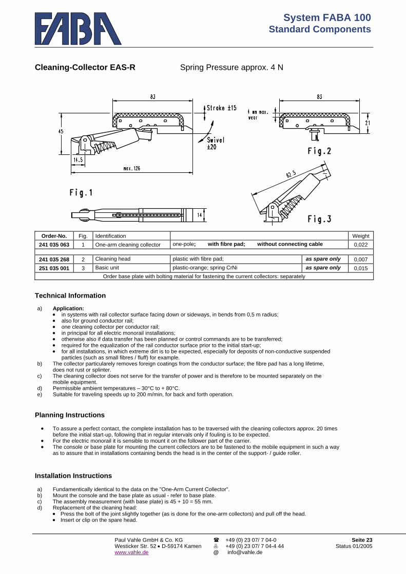
System FABA 100Standard Components
Paul Vahle GmbH & Co. KG Westicker Str. 52 • D-59174 Kamenwww.vahle.de
+49 (0) 23 07/ 7 04-0 +49 (0) 23 07/ 7 04-4 44
Seite 23Status 01/2005
Cleaning-Collector EAS-R Spring Pressure approx. 4 N
Order-No. Fig. Identification Weight 241 035 063 1 One-arm cleaning collector one-pole; with fibre pad; without connecting cable 0,022
241 035 268 2 Cleaning head plastic with fibre pad; as spare only 0,007 251 035 001 3 Basic unit plastic-orange; spring CrNi as spare only 0,015
Order base plate with bolting material for fastening the current collectors: separately Technical Information a) Application: • in systems with rail collector surface facing down or sideways, in bends from 0,5 m radius; • also for ground conductor rail; • one cleaning collector per conductor rail; • in principal for all electric monorail installations; • otherwise also if data transfer has been planned or control commands are to be transferred; • required for the equalization of the rail conductor surface prior to the initial start-up; • for all installations, in which extreme dirt is to be expected, especially for deposits of non-conductive suspended
particles (such as small fibres / fluff) for example. b) The collector particularely removes foreign coatings from the conductor surface; the fibre pad has a long lifetime,
does not rust or splinter. c) The cleaning collector does not serve for the transfer of power and is therefore to be mounted separately on the
mobile equipment. d) Permissible ambient temperatures – 30°C to + 80°C. e) Suitable for traveling speeds up to 200 m/min, for back and forth operation.
Planning Instructions • To assure a perfect contact, the complete installation has to be traversed with the cleaning collectors approx. 20 times
before the initial start-up, following that in regular intervals only if fouling is to be expected. • For the electric monorail it is sensible to mount it on the follower part of the carrier. • The console or base plate for mounting the current collectors are to be fastened to the mobile equipment in such a way
as to assure that in installations containing bends the head is in the center of the support- / guide roller. Installation Instructions a) Fundamentically identical to the data on the "One-Arm Current Collector". b) Mount the console and the base plate as usual - refer to base plate. c) The assembly measurement (with base plate) is 45 + 10 = 55 mm. d) Replacement of the cleaning head: • Press the bolt of the joint slightly together (as is done for the one-arm collectors) and pull off the head. • Insert or clip on the spare head.
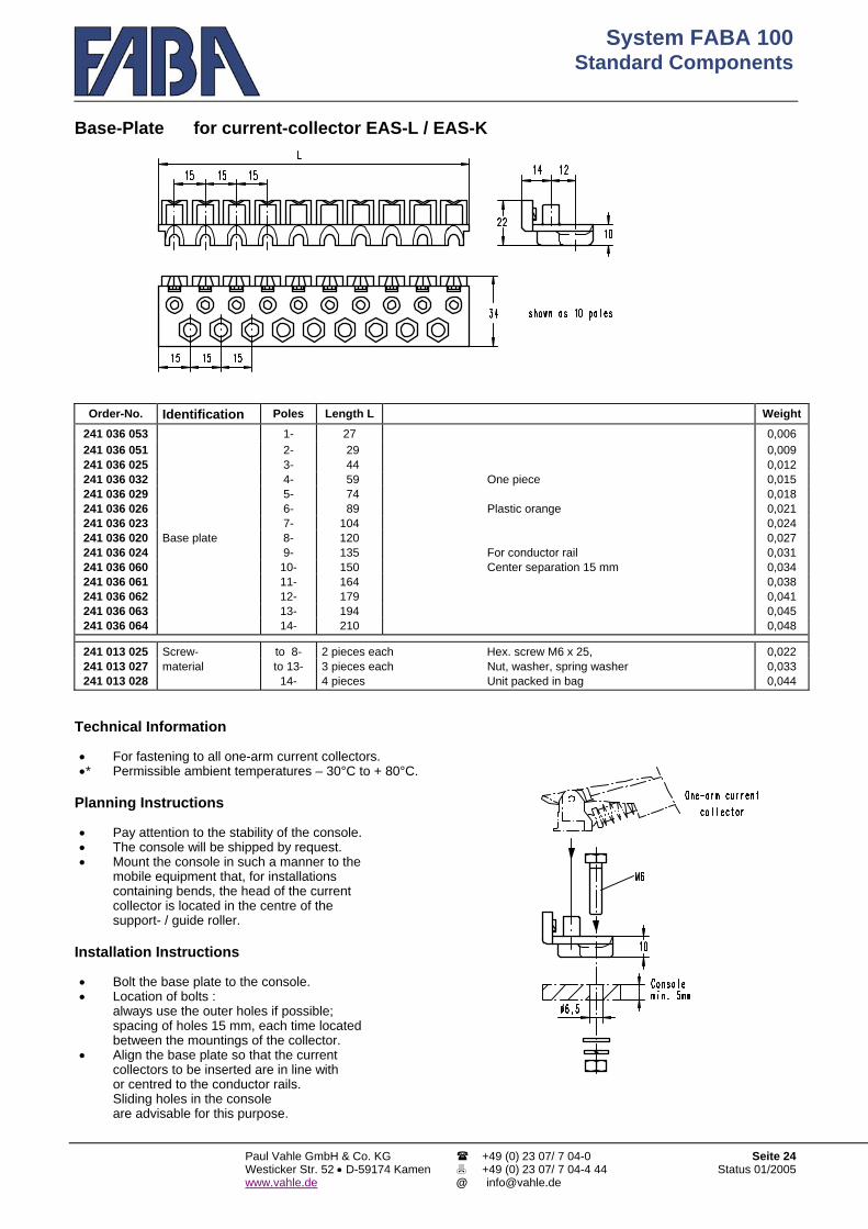
System FABA 100Standard Components
Paul Vahle GmbH & Co. KG Westicker Str. 52 • D-59174 Kamenwww.vahle.de
+49 (0) 23 07/ 7 04-0 +49 (0) 23 07/ 7 04-4 44
Seite 24Status 01/2005
Base-Plate for current-collector EAS-L / EAS-K
Order-No. Identification Poles Length L Weight 241 036 053 1- 27 0,006 241 036 051 2- 29 0,009 241 036 025 3- 44 0,012 241 036 032 4- 59 One piece 0,015 241 036 029 5- 74 0,018 241 036 026 6- 89 Plastic orange 0,021 241 036 023 7- 104 0,024 241 036 020 Base plate 8- 120 0,027 241 036 024 9- 135 For conductor rail 0,031 241 036 060 10- 150 Center separation 15 mm 0,034 241 036 061 11- 164 0,038 241 036 062 12- 179 0,041 241 036 063 13- 194 0,045 241 036 064 14- 210 0,048
241 013 025 Screw- to 8- 2 pieces each Hex. screw M6 x 25, 0,022 241 013 027 material to 13- 3 pieces each Nut, washer, spring washer 0,033 241 013 028 14- 4 pieces Unit packed in bag 0,044
Technical Information • For fastening to all one-arm current collectors. •* Permissible ambient temperatures – 30°C to + 80°C.
Planning Instructions • Pay attention to the stability of the console. • The console will be shipped by request. • Mount the console in such a manner to the
mobile equipment that, for installations containing bends, the head of the current collector is located in the centre of the support- / guide roller.
Installation Instructions • Bolt the base plate to the console. • Location of bolts :
always use the outer holes if possible; spacing of holes 15 mm, each time located between the mountings of the collector.
• Align the base plate so that the current collectors to be inserted are in line with or centred to the conductor rails. Sliding holes in the console are advisable for this purpose.

System FABA 100Standard Components
Paul Vahle GmbH & Co. KG Westicker Str. 52 • D-59174 Kamenwww.vahle.de
+49 (0) 23 07/ 7 04-0 +49 (0) 23 07/ 7 04-4 44
Seite 25Status 01/2005
Current Collector PAS-K Spring Pressure approx. 4 N Current Collector PAS-L Spring Pressure approx. 6 N
Order-No. Fig Identification Weight 241 035 325 1 Double-Arm Spade black head 1 pole; 0,040 241 035 326 Collector Ground Connection yellow head and foot 0,040
241 035 155 1 Double-Arm Screw black head Cu Shoe; 0,040 241 035 156 Collector Ground Connection M4 yellow head and foot 0,040
241 035 167 2 Double-Arm Screw black head Plastic Body 0,040 241 035 168 Collector Ground Connection M4 yellow head and foot 0,040
241 035 331 3 Double-Arm with Spade black head CrNi-Spring 0,048 241 035 332 Collector longer arm Ground Connection yellow head and foot Stainless steel 0,048
241 035 160 3 Double-Arm with Screw black head without cable 0,048 241 035 161 Collector longer arm Ground Connection M4 yellow head and foot 0,048
241 035 163 4 Double-Arm with Screw black head without collector 0,048 241 035 164 Collector longer arm Ground Connection M4 yellow head and foot bracket 0,048
241 035 327 1 Spade Body orange 0,040
Connection with 241 035 157 1 Double Arm current
collector Screw Head grey Silver Shoe 0,040
Connection M4 241 035 333 3 Spade Body orange 0,048
For Data Transmission
Connection with 241 035 162 3 with Screw Head grey Silver Shoe 0,048
Longer Arm Connection M4

System FABA 100Standard Components
Paul Vahle GmbH & Co. KG Westicker Str. 52 • D-59174 Kamenwww.vahle.de
+49 (0) 23 07/ 7 04-0 +49 (0) 23 07/ 7 04-4 44
Seite 26Status 01/2005
Continuation – Current Collector PAD-K Spring Pressure approx. 4 N Current Collector PAD-L Spring Pressure approx. 6 N
Order-No. Fig Identification Weigth 241 035 165 5 Double-Arm With two shoes phase Spade black Cu-collector shoe 0,038 241 035 166 Collector ground Connection yellow Head and Foot 0,038
241 035 140 6 Double-Arm With two shoes phase Spade black Cu-collector shoe 0,046 241 035 141 Collector longer arm ground Connection yellow Head and Foot 0,046
Attention ! Systems with collectors with double long arms and pick-up guides have a larger installation measurement being 100 mm.

System FABA 100Standard Components
Paul Vahle GmbH & Co. KG Westicker Str. 52 • D-59174 Kamenwww.vahle.de
+49 (0) 23 07/ 7 04-0 +49 (0) 23 07/ 7 04-4 44
Seite 27Status 01/2005
Doublearm current collector accessories – continuation –
Order No. Fig. Name Weight 241 040 011 20 Amp. 1.5 mm² Outer -∅ 4.0 Single-wire; 0.030 241 040 013 Connection cable 30 Amp. black 2.5 mm² Outer -∅ 4.5 Halogen free 0.040 241 040 014 for screw 40 Amp. 4 mm² Outer -∅ 6.0 Highly flexible; 0.080 241 040 016 7 connection 50 Amp. 6 mm² Outer -∅ 7.5 1000 V; 0.120 241 040 012 Ground 2.5 mm² Outer -∅ 3,9 One-end M4; 0.034 241 040 015 (for collector Ground green-yellow 4 mm² Outer -∅ 4,9 1 m long 0.056 241 040 017 Fig. 1, 2, 3, 4) Ground 6 mm² Outer -∅ 6,3 (other lengths on request) 0.072
Data connection cable 0.5 mm² Outer -∅ 3.6; with shielding; 241 040 018 7 for screw connection grey single-wire; highly flexible; one-sided M4 0.022
(for collector Fig. 1 and 3) 1 m long (other lengths on request) 241 040 060 Connection cable 20 Amp. black 1.5 mm² Outer -∅ 4.0 Single-wire; highly flexible; 1000 V; 0.030 241 040 061 8 for plug terminal 20 Amp. black 2.5 mm² Outer -∅ 4.5 One-end with DIN plug; 0.040 241 040 062 (for collector Fig. 1,3,5,6) PE green-yellow 2.5 mm² Outer -∅ 4.0 1 m long (otherwise, on request) 0.034 241 013 110 2- pole L = 75 For sliding contact rails 0.056 241 013 111 3-/ 4-pole L = 100 Centre point spacing 15 mm; 0.064 241 013 112 5-/ 6-pole L = 125 complete : 0.072 241 013 113 9 Support rail for holding 7-/ 8-pole Length L = 150 with 2 end clamps 0.080 241 013 114 collectors 9-/10-pole L = 200 and 2 attachment screws; 0.095 241 013 115 11-/12-pole L = 225 0.104 241 013 116 13-/14-pole L = 250 Design, galv. steel Zn 0.112
Length L = 400 mm; for any desired sliding contact rails centre spacing; 241 013 117 9 Support rail Complete : With 2 end clamps and 2 attachment screws; 0.160
Design, galv. steel Zn 241 024 075 10 a Spacer piece One-piece made of plastic; Width B = Centre spacing minus 15; 0.005
State conductor rail centre spacing when ordering
251 035 055 10 b Base plate orange One-piece made of plastic; diameter d = 8 Only as 0,006 251 035 056 Base plate Groud yellow One-piece made of plastic; diameter d = 6 spare 0,006 241 035 321 241 035 322 241 035 323
11 Replacement head for plug connection (for collector Fig. 1 and 3)
Groud Data-
orange yellow grey
} Cu-sliding carbon contact; for plug connection 4.8 x 0.8 Silver-sliding carbon contact; with plug connection 4.8 x 0.8
Only as spare
0,017 0,017 0,017
241 035 315 241 035 316 241 035 317
11 Replacement head for screw connection (for collector Fig. 1,2,3,4)
phase Groud Data-
black yellow grey
} Cu-sliding carbon contact; for screw connection M4 Silver-sliding carbon contact; for screw connection M4
Only as spare
0,017 0,017 0,017
241 035 420
241 035 421
12
Replacement head (for collector Fig. 5 and 6)
phase
Groud
black yellow
Cu-sliding carbon contact; with plug connection 4.8 x 0.8
Only as spare
0,015
0,015

System FABA 100Standard Components
Paul Vahle GmbH & Co. KG Westicker Str. 52 • D-59174 Kamenwww.vahle.de
+49 (0) 23 07/ 7 04-0 +49 (0) 23 07/ 7 04-4 44
Seite 28Status 01/2005
Double-Arm Current Collector - Continuation - Technical Information a) • Permissible Ambient temperature – 30°C to + 80°C. • Collector Cables to be ordered separately (use only special Faba cables). • Other colores on request. • Foot and head are self centering when disengaged from the conductor rail. • Ground Collector is 4 mm higher. • The head is spring loaded ± 5. • Collector Cables must not be pulled taught. • Suitable For speeds up till 400 m/min. and back and forth motion.
For systems where contact surface is facing sideways or down. For bends above 500 mm Radius. Suitable for 20 - 50 Amps at 40øC Ambient temperature depending on the correct cable see page 28.
b) Allowable continuous current depends upon the connection line 20 A, 30 A, 40 A or 50 A up to 40°C ambient temperature.
At higher temperatures, reduction in compliance with Table 3 in List IS 100 A. c) Design with long arm :
Preferred place of installation, for example, crane systems, meaning when longer lifting / longer swing is necessary. Attention ! Installed dimension for systems with hopper : 100 mm.
d) Design with double contact :
Max. allowable continuous current 20 A (otherwise as for b). Used preferably for control functions. e) Parallel arm slider for data transmission :
Design of the connection line with shielding : single shielding. f) For sliding contact rail centre spacing larger than 15 mm, observe: • min. 30 mm is necessary, for example, when laying in moist areas / rooms or in the open air; • All parallel arm sliding contacts are suitable; • Do not install any raising / lowering hoppers in the system.
Planning Instructions • It is essential that the stroke and swivel tolerances of the collector are held on the whole track system . • Collector holder bracket are to be situated on carriers where bends exists so that the collector head is situated middle of the
drive roller of the carrier . • Normal practice is a one head collector for each conductor rail . Please see the special list IS 100 D for data transmission
with collector . •* When rail centers of more than 15 mm are required :
Use holder bracket 400 mm long (shorten to requirements); and use spacer Fig. 7 between each collector .
Installation Instructions a) Screw collector bracket on holder. b) Clip Collector base starting from the back of the
collector with a turning motion onto the holding bracket for spacing more than 15 mm use appropiate number of spacers width 15 mm making sure collectors line up middle to the conductor rail. Make sure the ground collector (yellow head) is positioned in the ground conductor rail.
c) Cable connection : • For reliable function use only Faba cables highly flexible function. • Cable connection screw-on type (Fig. 13)
Pass the cable end without terminal through the top pivot then through the hole in the base section and connect. Tighten Cable with screw connection M4 on to collector shoe, making sure the tongue on the collector shoe is positioned between the ring terminal and locking washer.
• Cable connection push on type (Fig. 14) Pass Cable through top pivot make sure female terminal fits secure on make terminal allow slag on cable for future Shoe change before securing cable.
• Make sure cables are not twisted, the head must be allowed to pivot treely in all directions. Failure to do so will cause a bad function of the collector and cause excessive wear on collector shoes.
d) Shoe change: • For fig. 13 : Press head down and hold. Tilt head backwards – arrow 3. • For fig. 14 : toward arm and pull off – arrow 4.

System FABA 100Standard Components
Paul Vahle GmbH & Co. KG Westicker Str. 52 • D-59174 Kamenwww.vahle.de
+49 (0) 23 07/ 7 04-0 +49 (0) 23 07/ 7 04-4 44
Seite 29Status 01/2005
Current collector PA DS-20 Spring Pressure approx. 7 N
Order No. Fig. Identification Weight 241 035 710 1 Parallel arm , double contact Plug Head, black Cu-collector shoe 0.055 241 035 711 curr. coll. PE connection Head + base,
yellow 0.055
241 040 077 2 Connecting cable 20 A black 2.5 mm² outer-∅ 4,5 Single-core; halogenfree, 0.042
highly-flexible; 1000 V; 1 m long 241 040 085 PE green-yellow 2.5 mm² outer-∅ 3,9 (Special designs on request) 0.036 241 013 111 3-/ 4-poles L = 100 Centre distance: 15 mm; 0.064 241 013 112 3 Supporting rail 5-/ 6-poles L = 125 complete: 0.072 241 013 113 7-/ 8-poles Length L = 150 with 2 end clamps 0.080 241 013 114 9-/10-poles L = 200 and 2 fastening screws 0.095 251 035 055 4 Base plate orange one piece, plastic, ∅ d = 8 Only if 0.006 251 035 056 Base plate PE yellow one piece, plastic, ∅ d = 6 repl. 0.006 241 035 705 241 035 706
5 2 replacement heads for plug connection
PEblack yellow Cu-collector shoe; for plug connection 6.3 x 0.8 Only if
repl. 0.028 0.028
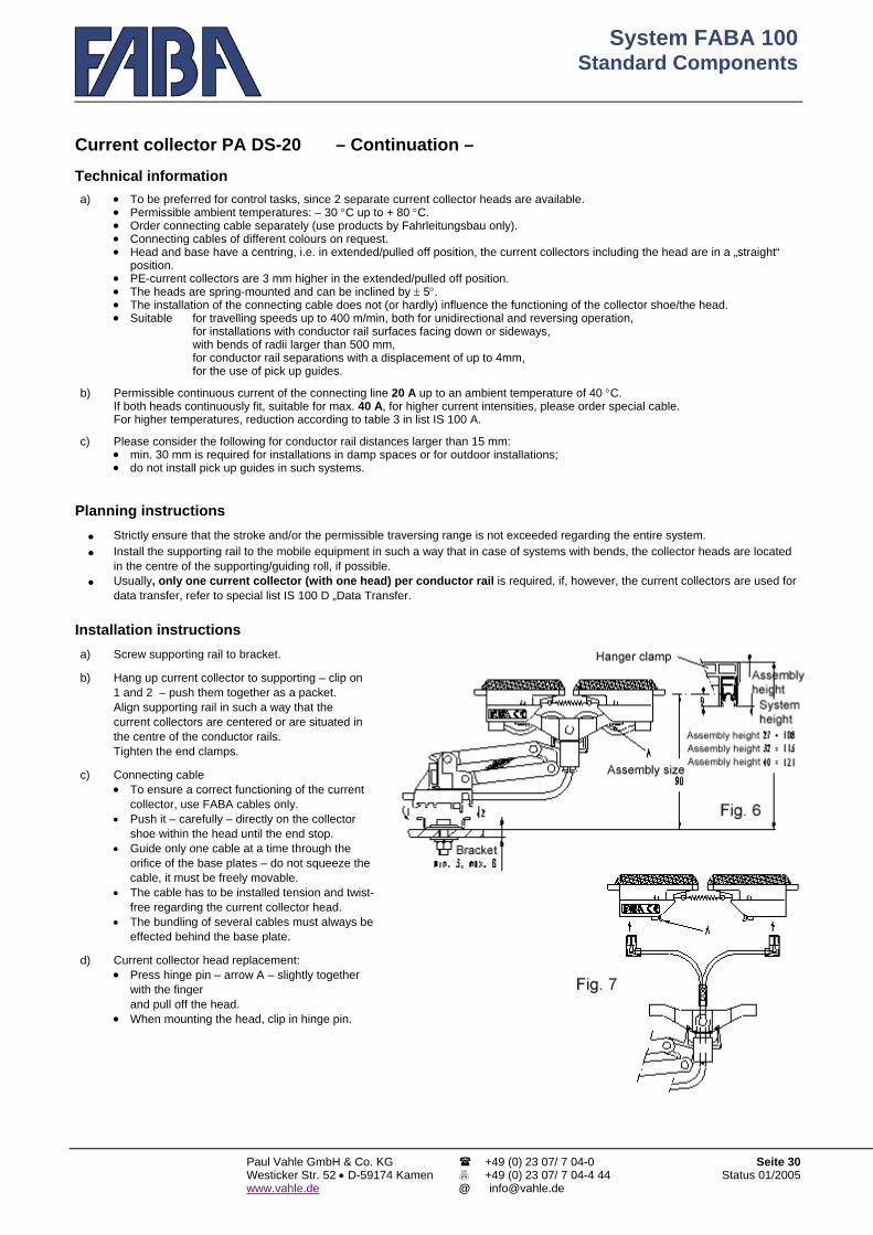
System FABA 100Standard Components
Paul Vahle GmbH & Co. KG Westicker Str. 52 • D-59174 Kamenwww.vahle.de
+49 (0) 23 07/ 7 04-0 +49 (0) 23 07/ 7 04-4 44
Seite 30Status 01/2005
Current collector PA DS-20 – Continuation – Technical information a) • To be preferred for control tasks, since 2 separate current collector heads are available. • Permissible ambient temperatures: – 30 °C up to + 80 °C. • Order connecting cable separately (use products by Fahrleitungsbau only). • Connecting cables of different colours on request. • Head and base have a centring, i.e. in extended/pulled off position, the current collectors including the head are in a „straight“
position. • PE-current collectors are 3 mm higher in the extended/pulled off position. • The heads are spring-mounted and can be inclined by ± 5°. • The installation of the connecting cable does not (or hardly) influence the functioning of the collector shoe/the head. • Suitable for travelling speeds up to 400 m/min, both for unidirectional and reversing operation,
for installations with conductor rail surfaces facing down or sideways, with bends of radii larger than 500 mm, for conductor rail separations with a displacement of up to 4mm, for the use of pick up guides.
b) Permissible continuous current of the connecting line 20 A up to an ambient temperature of 40 °C.
If both heads continuously fit, suitable for max. 40 A, for higher current intensities, please order special cable. For higher temperatures, reduction according to table 3 in list IS 100 A.
c) Please consider the following for conductor rail distances larger than 15 mm: • min. 30 mm is required for installations in damp spaces or for outdoor installations; • do not install pick up guides in such systems.
Planning instructions • Strictly ensure that the stroke and/or the permissible traversing range is not exceeded regarding the entire system. • Install the supporting rail to the mobile equipment in such a way that in case of systems with bends, the collector heads are located
in the centre of the supporting/guiding roll, if possible. • Usually, only one current collector (with one head) per conductor rail is required, if, however, the current collectors are used for
data transfer, refer to special list IS 100 D „Data Transfer. Installation instructions a) Screw supporting rail to bracket. b) Hang up current collector to supporting – clip on
1 and 2 – push them together as a packet. Align supporting rail in such a way that the current collectors are centered or are situated in the centre of the conductor rails. Tighten the end clamps.
c) Connecting cable • To ensure a correct functioning of the current
collector, use FABA cables only. • Push it – carefully – directly on the collector
shoe within the head until the end stop. • Guide only one cable at a time through the
orifice of the base plates – do not squeeze the cable, it must be freely movable.
• The cable has to be installed tension and twist-free regarding the current collector head.
• The bundling of several cables must always be effected behind the base plate.
d) Current collector head replacement: • Press hinge pin – arrow A – slightly together
with the finger and pull off the head.
• When mounting the head, clip in hinge pin.

System FABA 100Standard Components
Paul Vahle GmbH & Co. KG Westicker Str. 52 • D-59174 Kamenwww.vahle.de
+49 (0) 23 07/ 7 04-0 +49 (0) 23 07/ 7 04-4 44
Seite 31Status 01/2005
Tandem Collector DE AS-20 Spring Pressure approx. 2 x 4 N
Order No.. Fig. Identification Weight 241 035 750 1 DEAS-Collector Spade- Black Head Copper Shoe 0,080 241 035 751 completed with 2 cables Ground Terminal Yellow Head and Foot Copper Shoe 0,082 241 035 752 1 Spade Terminal for
connecting Data Grey Head Silver Shoe 0,078
241 035 775 2 Front Collector Body spare 0,012 241 035 776 Ground Foot Yellow only 0,012 241 035 780 3 Rear Collector Body spare 0,014 241 035 781 Ground Foot Yellow only 0,014 241 035 765 4 Front Replacement Head Spade- Black Copper Shoe spare 0,016 241 035 766 Ground Terminal Yellow Copper Shoe only 0,016 241 035 767 Data Grey Silver Shoe 0,014 241 035 770 5 Rear Replacement Head Spade Black Copper Shoe spare 0,016 241 035 771 Ground Terminal Yellow Copper Shoe only 0,016 241 035 772 Data Grey Silver Shoe 0,014 251 035 810 6 Base plate w. integrated Orange Bolt-d = 5 spare 0,018 251 035 811 triple spade terminal Ground Yellow Bolt-d = 6 only 0,018 241 035 801 3-/ 4-poles L = 100 0,078 241 035 802 7 Support 5-/ 6-poles Length L = 125 0,090 241 035 803 Rail 7-/ 8-poles L = 150 0,102 241 035 804 9-/10-poles L = 175
Center point spacing 15 mm complete with 2 end clamps and 2 attachment screws 0,114
241 040 921 Anschlussleitung DE AS 2,5 mm² L = 1 m Phase Gerader Steckanschluss 6,3x0,8 0,038 241 040 922 L = 2 m Phase 0,076 241 040 923 L = 3 m Phase 0,114 241 040 924 L = 4 m Phase 0,152

System FABA 100Standard Components
Paul Vahle GmbH & Co. KG Westicker Str. 52 • D-59174 Kamenwww.vahle.de
+49 (0) 23 07/ 7 04-0 +49 (0) 23 07/ 7 04-4 44
Seite 32Status 01/2005
Order No.. Identification Weight
241 040 925 Feed Cable DE AS 2,5 mm² L = 1 m PE Straight Connection 6,3x0,8 0,033 241 040 926 L = 2 m PE 0,066 241 040 927 L = 3 m PE 0,099 241 040 928 L = 4 m PE 0,132 241 040 931 Feed Cable DE AS 2,5 mm² L = 1 m Phase Cornered Connection 6,3x0,8 0,038 241 040 932 L = 2 m Phase 0,076 241 040 933 L = 3 m Phase 0,114 241 040 934 L = 4 m Phase 0,152 241 040 935 L = 1 m PE 0,033 241 040 936 L = 2 m PE 0,066 241 040 937 L = 3 m PE 0,099 241 040 938 L = 4 m PE 0,132
Technical Information a) • Suitable for control Signals because of 2 fully independent collector heads. • Permissible Ambient Temperature - 30 °C till + 80 °C. • Phase and Ground Collector are not interchangeable and have different colors. • Female Angled or Female Straight terminal 6,3x0.8 are used for further connection. • Further connecting cable must be ordered separately. • Foot and Head are self centering in take out position ;enabling easy insertion in rail. • Ground Collector is 3 mm higher enabling first in last out saftey contact. • Suitable for speeds till 400m/min and back and forth operations -
- - -
for contact surface facing down or sideways for bending min 500mm,in all directions for 4mm transfer air gap disalignment using larger transfer caps for use with pick-up guides
b) Permissible continuous current 20 A till 40 C Ambient Temperature. At higher temperatures reduce as to table.
c) At rail center spacing of more than the standard 15 mm • Pick up guides will not function
In damp environments or outside applications at least 30mm centering of collector rails is necessary, to avoid current creapage.
Planning Instructions • For the desired free movement of the collectors, pay special attention that the stroke
and swivel tolerances are maintained over the whole conductor rail system. • Install collector assembly as close as possible middle to the carrier drive roller. • The steel console for connecting the collector support rail must be parallel to the conductor rails to avoid negative
function of the collector assembly. Installation Instructions Fig ( 8 ) a) Secure collector support rail on proposed
steel console max 6mm. b) Clip tandem collectors on support rail see
movement l and 2 on Fig 8. Push collectors together centering them to conductor rails Tighten end clamps If necessary loosen the two nuts below for final centering and slide whole unit up or down to center ; Fasten after completion
c) Collector Cable: • The Tandem collector is already furnished
with 2 cables which are secured to a tripled spade terminal at the base
• One spade terminal is left for a straight or angled female terminal 6,3x0,8 mm
• Cables can be chosen from the catalog (or terminals )
d) Collector Head Change ( Fig 9 ): • Pull off female terminal from collector shoe. • With finger push retaining lug ( A ) together and pull off head. • To install, push lug through collector arm hole and push terminal
on.

System FABA 100Standard Components
Paul Vahle GmbH & Co. KG Westicker Str. 52 • D-59174 Kamenwww.vahle.de
+49 (0) 23 07/ 7 04-0 +49 (0) 23 07/ 7 04-4 44
Seite 33Status 01/2005

System FABA 100 FABA 30 Conductor Rail
Paul Vahle GmbH & Co. KG Westicker Str. 52 • D-59174 Kamen www.vahle.de
+49 (0) 23 07/ 7 04-0 +49 (0) 23 07/ 7 04-4 44
Seite 1Status 01/2005
FABA 30 Conductor Rail
Conductor Rail FABA 100 System
for mobile equipment

System FABA 100 FABA 30 Conductor Rail
Paul Vahle GmbH & Co. KG Westicker Str. 52 • D-59174 Kamenwww.vahle.de
+49 (0) 23 07/ 7 04-0 +49 (0) 23 07/ 7 04-4 44
Seite 2Status 01/2005
We have extended our insulated FABA 100 Conductor Rail System to include a low-priced copper rail.
The FABA 30 Contact Rail i s s u i t a b l e • A b o v e a l l as additional control rail for the transmission of information like electronic data; • B u t a l s o as an outside rail for the transmission of continuous currents up to 30 Ampere.
In the search for a low-priced design, our Development Department took completely new directions which have led to an absolutely new solution : The metal rail with the minimal cross-section of 5 mm² is manufactured simultaneously with the insulating jacket in one extrusion operation. Both form a unit together. The FABA 30 conductor rail has the same outside dimensions as the FABA 40 and FABA 100 conductor rails and can be combined with these rails. It goes without saying that the FABA 30 conductor rail has all of the advantages of our FABA 40 and FABA 100 rails, independent of whether it is used exclusively in a system or additionally. With the FABA 30 conductor rail, you are using a technically high-valued product and thereby an optimum addition to our FABA 100 conductor rail system; in the context of the project planning, costs can be saved in the erection of the system. Please contact us if you require our advice or our support especially in the project planning/installation. Dimension a = H a n g e r s p a c i n g in straight lines, max. 600 mm, max. 300 mm in curves; with the following
components, maintain the following at least on one side : b = To rail connector = min. 100 mm, max. 200 mm c = To expansion point = min. 100 mm, max. 200 mm d = To electrical separation point = min. 100 mm, max. 200 mm e = To mechanical separation point
(if single-pole transfer cap) or to end cap
= min. 100 mm, max. 200 mm
f = To cone = max. 500 mm g = S y s t e m h e i g h t = Top edge of hanger clamp to lower edge of collector mounting :
as for FABA 40 / FABA 100.
FABA – a Product of VAHLE
Overall height

System FABA 100 FABA 30 Conductor Rail
Paul Vahle GmbH & Co. KG Westicker Str. 52 • D-59174 Kamenwww.vahle.de
+49 (0) 23 07/ 7 04-0 +49 (0) 23 07/ 7 04-4 44
Seite 3Status 01/2005
01 FABA 30 Conductor Rail As control rail or for continuous currents up to 30 Ampere; 5 m long; sliding surface arrangement facing downwards
or to the side optionally; radii from 0.5 m; ambient temperatures from - 30°C to + 55°C (higher temperatures on enquiry); same outside dimensions as FABA 40 / FABA 100, so that combinations with each other are possible without restriction; Same conditions with respect to the General IS 100 A List on travel stretch, space, hand area and data transmission.
02 FABA 30 Rail Connector Simple installation without tools by pushing together. Can accept up to 6 mm rail expansion. 03 Hanger Clamp The same models of FABA 40 / FABA 100 are used, so that rail centre spacing minimum and usually is 15 mm; the
overall height depends upon local conditions. 04 FABA 30 Expansion Lengthwise changes of the sliding line are compensated for with the butt connector; the expansion bridge for
expansions up to 20 mm with electrical bridging is illustrated in the figure; furthermore, expansion rails for expansions of 40 mm and 60 mm are available; a fixed point is to be located between the expansion points.
05 FABA 30 Electrical Separation For example, at repair stretches or to trigger control impulses, with the possibility of line connection on one or both
sides; the separation accepts expansions up to 20 mm. 06 FABA 30 Mechanical Separation For example, at switches, lifting stations, sliding platforms, with the possibility of line connection on one side or both
sides; shown as multi-pole transition (also available as single-pole transition optionally). 07 Pick – Up Guides For larger sliding rail interruptions for the raising and lowering of the collectors; the same multiple-pole designs of
FABA 40 / FABA 100 are used. For systems with pick up guides, use only parallel arm collector. 08 FABA 30 End Cap At the end of the system with the possibility of feeding; used also for ground rail. 09 Slider The same listed designs of FABA 40 / FABA 100 (List IS 100 B) are applicable. For systems with pick up guides, use
only parallel arm collector.

System FABA 100 FABA 30 Conductor Rail
Paul Vahle GmbH & Co. KG Westicker Str. 52 • D-59174 Kamenwww.vahle.de
+49 (0) 23 07/ 7 04-0 +49 (0) 23 07/ 7 04-4 44
Seite 4Status 01/2005
Conductor Rail
der No. Fig. Description Length Weight 200 501 499 5 m Metal Insulating Orange 0.530
1 FABA 30 coductor rail rail jacket 200 502 499 5 m Copper Hard PVC Ground Yellow with green stripes 0.530
241 000 007 2 Bending
profile Grey 5 m PVC With brass strip Remains in curved piece 0.460
241 000 006 3 Bending profile
Red 5 m PVC Can be used repeatedly 0.250
241 045 001 4 Bending machine ( Identical to FABA 40 / 100 ) For manual operation 11.20 518 503 000 Fine file 0.095 518 505 000 with-
out Hacksaw ( Identical to FABA 40 / 100 ) 0.135
518 505 010 Saw blades 12 pcs; for replacement 0.038 Technical Information • Allowable ambient temperatures With continuous ambient temperature - 30 °C to + 55 °C. up to [ °C] • Metal rails and insulating jackets are equally long; lengthwise displacements 35 40 45 50 55 relative to each other are not possible Allowable continuous current [A] 30 27 24 21 18 (as if extruded together). at 100 % Duty cycle • Metal rail cross-section 5 mm². Resistance with alternating current
(impedance) 4.42 4.75 5.08 5.39 5.66
• Linear coefficient of expansion [Ohm/km] with direct current 4.22 4.53 4.85 5.14 5.41 α = 17 ⋅ 10 -6 [K-1].
Planning Information • In principle, as for FABA 40 / FABA 100. • Hanger spacing : max. 600 mm in straight lengths; max. 300 mm in curves. • Conductor rails can be shortened on location. • Radii are possible in all directions : from 0.5 m ″on location″.
Grey bending strips necessary only with continuous radii under 0.75 m or with rail separation in the radius. Assembly Instructions a) In principle, as for FABA 40 / FABA 100. b) Hanger spacing: max. 600 mm in straight lengths; max. 300 mm. in curves. c) Shorten: With fine-toothed metal saw, begin sawing from the sliding surface. Deburr cut surfaces – especially the metal sliding
surface – carefully with a fine file. d) Curves: Manufacture with bending machine and bending profile; “on location” in general, smallest bending radius 500 mm to all
sides. • Determine approximate length of curve and mark on the insulating jacket with felt pen. Mark min. 150 mm from
beginning of rail (beginning and end cannot be bent, remain straight). • When bending over the sliding surface or the rail back, insert grey bending profile.
The ends to be connected must be free of grey bending strips 30 mm each. • When bending over rail broad side, insert grey bending profile as before and insert red bending profile in the sliding
surface slot. • Slide rail into the bending machine, until the first curve marking is located centered over one of the lower rollers.
Depending on required radius, tighten the upper roller. Guide rail through machine to the second marking. Correction is possible by performing again. For same curve, note the scale setting.
• If two rail curves must be joined to each other, shorten the rails to be connected by the straight end (approx. 150 mm).
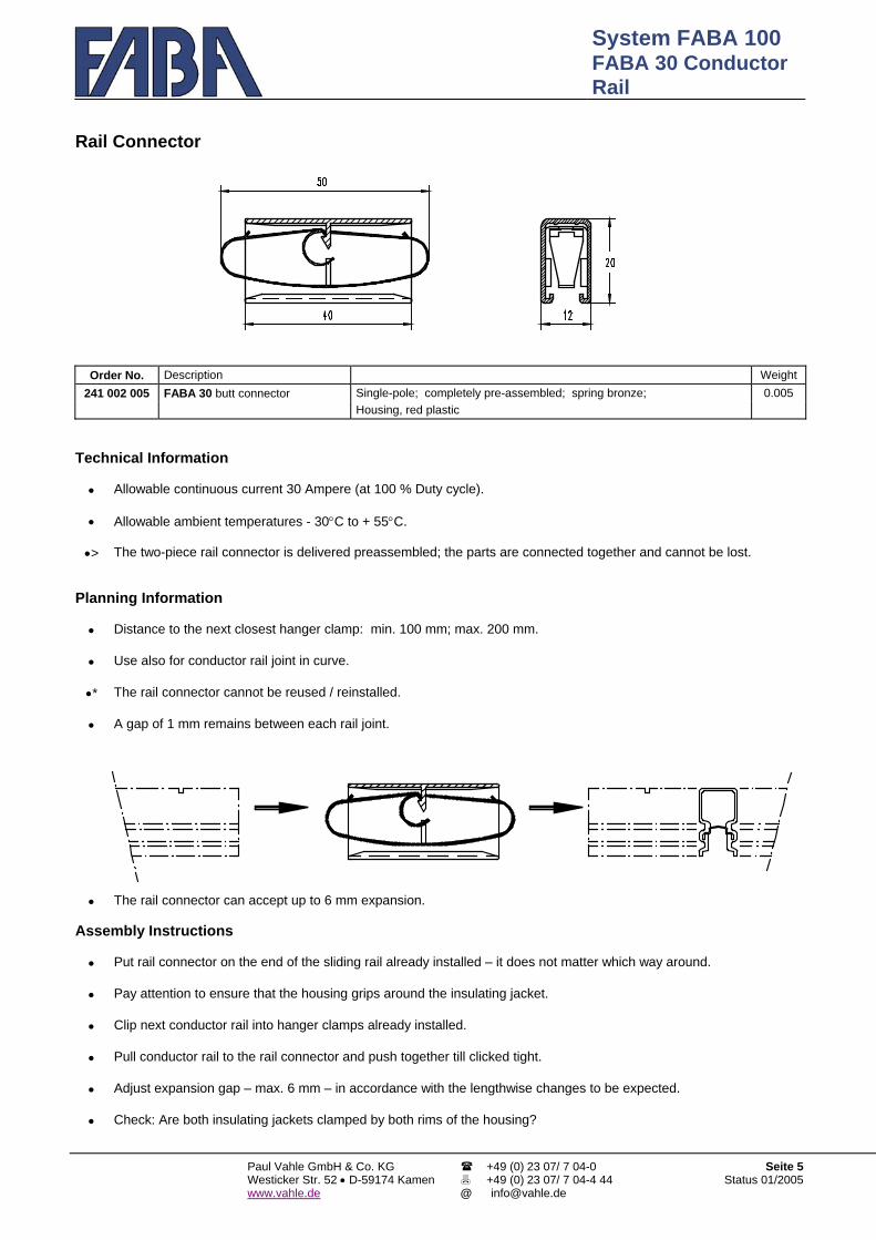
System FABA 100 FABA 30 Conductor Rail
Paul Vahle GmbH & Co. KG Westicker Str. 52 • D-59174 Kamenwww.vahle.de
+49 (0) 23 07/ 7 04-0 +49 (0) 23 07/ 7 04-4 44
Seite 5Status 01/2005
Rail Connector
Order No. Description Weight
241 002 005 FABA 30 butt connector Single-pole; completely pre-assembled; spring bronze; 0.005 Housing, red plastic
Technical Information • Allowable continuous current 30 Ampere (at 100 % Duty cycle). • Allowable ambient temperatures - 30°C to + 55°C. •> The two-piece rail connector is delivered preassembled; the parts are connected together and cannot be lost.
Planning Information • Distance to the next closest hanger clamp: min. 100 mm; max. 200 mm. • Use also for conductor rail joint in curve. •* The rail connector cannot be reused / reinstalled. • A gap of 1 mm remains between each rail joint.
• The rail connector can accept up to 6 mm expansion. Assembly Instructions • Put rail connector on the end of the sliding rail already installed – it does not matter which way around. • Pay attention to ensure that the housing grips around the insulating jacket. • Clip next conductor rail into hanger clamps already installed. • Pull conductor rail to the rail connector and push together till clicked tight. • Adjust expansion gap – max. 6 mm – in accordance with the lengthwise changes to be expected. • Check: Are both insulating jackets clamped by both rims of the housing?
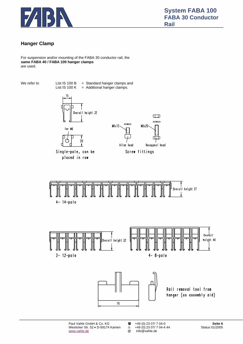
System FABA 100 FABA 30 Conductor Rail
Paul Vahle GmbH & Co. KG Westicker Str. 52 • D-59174 Kamenwww.vahle.de
+49 (0) 23 07/ 7 04-0 +49 (0) 23 07/ 7 04-4 44
Seite 6Status 01/2005
Hanger Clamp For suspension and/or mounting of the FABA 30 conductor rail, the same FABA 40 / FABA 100 hanger clamps are used. We refer to List IS 100 B = Standard hanger clamps and List IS 100 K = Additional hanger clamps.

System FABA 100 FABA 30 Conductor Rail
Paul Vahle GmbH & Co. KG Westicker Str. 52 • D-59174 Kamenwww.vahle.de
+49 (0) 23 07/ 7 04-0 +49 (0) 23 07/ 7 04-4 44
Seite 7Status 01/2005
Power feeds
Order-No. Fig. Identification Weight 241 015 045 1 + 3 Power feed Without connecting cable Housing and plug in bag 0.007 241 015 046 1 + 3a FABA 30 Without connecting cable Housing, pluck and flat plug sleeve 1mm2 +
2,5mm2 in bag 0.010
241 015 042 1 + 2 Power feed With connecting cable 2.5 mm² Housing and connecting cable 1 m long 0.050 241 015 043 FABA 30 PE With connecting cable 2.5 mm² in bag 0.043 241 015 044 Data With connecting cable 2.5 mm² (other lengths on request) 0.043
241 026 055 1 Housing Plastic-red 0,005
241 026 024 3 Plug Bronze; for cross sections 1.5 mm² and 2.5 mm² Only 0.002 241 026 041 3a Plug Bronze; with plug connection 6.3x0,8 If re- 0,002
241 040 377 2 Connecting 2.5 mm² Outer-∅ 4.5 1 kV black Single-core, halogenfree,
flexible; placed 0.045
241 040 378 Cable 2.5 mm² Outer-∅ 3.9 PE green-yellow
One-side with plug; 0.038
241 040 379 1 m long Data 1.5 mm² Outer-∅ 5.1 grey (other lengths on request) 0.038
Technical information • Permissible continuous current depends on the feeder line (and of the ambient temperature) max. 30 A • Permissible ambient temperatures: – 30 °C up to + 55 °C
Planning instructions • Suitable for assembly heights larger than 27 mm, for all conductor rails including PE • Also suitable for bends larger than R = 1000 mm • Use enclosed receptacles only
Installation instructions • Treat conductor rail – as dimensioned (remove chips) • Put plug with connecting cable on the journal of the housing • Attach housing to conductor rail and displace it until it engages

System FABA 100 FABA 30 Conductor Rail
Paul Vahle GmbH & Co. KG Westicker Str. 52 • D-59174 Kamenwww.vahle.de
+49 (0) 23 07/ 7 04-0 +49 (0) 23 07/ 7 04-4 44
Seite 8Status 01/2005
Expansion – General information a) In principle, the same information and handling as for FABA 40 / FABA 100. b) Through fluctuations in the ambient temperatures or the heat generated, the
length of the conductor rail changes. Fixed points arrest the conductor rail at certain points, thus controlling any linear displacement.
c) Linear installations up to a length of 60 m only require a centered fixed point.
Each rail splice can compensate for a change of length of up to 6 mm. d) All other installations – i.e. straight rail sections longer than 60 m – will require
components compensating for the change of length: • Expansion rail for changes of length of up to 36 mm or 54 mm • Electrical separation; compensates for linear expansions of the conductor
rail up to 18 mm. It can also be exclusively used as an expansion bridge at the rail splice, in this case, however, a cable for electric bridging will be required.
e) F i x e d p o i n t s have always to be installed; these are components which
arrest the conductor rail in combination with a hanger clamp. Usually, they are to be installed in the centre between to expansion points, for radii preceding or following the bend, for counter directed bends, the fixed point is to be installed in the centre of the bend.
Equal fixed point as for FABA 40 / FABA 100 (list IS 100 B).
Apart from a good planning of the conductor rail installation, a correct and orderly installation is indispensable for the dependable operation and this not only for standard installations but also for extensively branched circuits - or for high travelling speeds, extreme fluctuations of temperature etc.
Because of our substantial experiences we are happy to be of assistance to you in the planning and suggest to have the installation carried out by our trained personnel - not in the least to guarantee the warranty on the proper function of our components or our FABA 100 system.
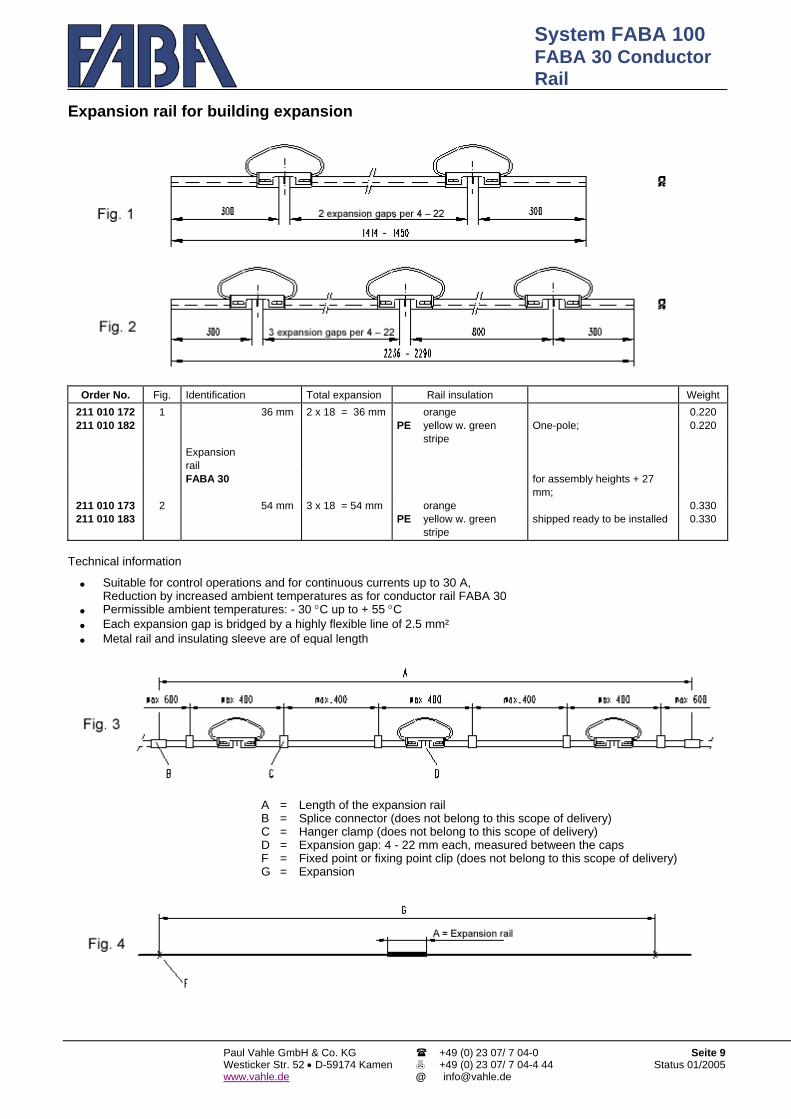
System FABA 100 FABA 30 Conductor Rail
Paul Vahle GmbH & Co. KG Westicker Str. 52 • D-59174 Kamenwww.vahle.de
+49 (0) 23 07/ 7 04-0 +49 (0) 23 07/ 7 04-4 44
Seite 9Status 01/2005
Expansion rail for building expansion
Order No. Fig. Identification Total expansion Rail insulation Weight 211 010 172 1 36 mm 2 x 18 = 36 mm orange 0.220 211 010 182 PE yellow w. green
stripe One-pole; 0.220
Expansion rail
FABA 30 for assembly heights + 27 mm;
211 010 173 2 54 mm 3 x 18 = 54 mm orange 0.330 211 010 183 PE yellow w. green
stripe shipped ready to be installed 0.330
Technical information • Suitable for control operations and for continuous currents up to 30 A,
Reduction by increased ambient temperatures as for conductor rail FABA 30 • Permissible ambient temperatures: - 30 °C up to + 55 °C • Each expansion gap is bridged by a highly flexible line of 2.5 mm² • Metal rail and insulating sleeve are of equal length
A = Length of the expansion rail B = Splice connector (does not belong to this scope of delivery) C = Hanger clamp (does not belong to this scope of delivery) D = Expansion gap: 4 - 22 mm each, measured between the caps F = Fixed point or fixing point clip (does not belong to this scope of delivery) G = Expansion

System FABA 100 FABA 30 Conductor Rail
Paul Vahle GmbH & Co. KG Westicker Str. 52 • D-59174 Kamenwww.vahle.de
+49 (0) 23 07/ 7 04-0 +49 (0) 23 07/ 7 04-4 44
Seite 10Status 01/2005
Expansion rail – Continuation – Planning instructions a) In princ, the same as for FABA 40/FABA 100. Max. permissible length of the expansion G [m] b) Mainly used for building and running rail
expansion joints Expansion rail Duty Difference in temperature [K]
FABA 30 Duty cycle 10 20 30 40 50 60 c) Suitable for expansion heights + 27 mm. 100 % 60 50 42 36 31 28 Expansion 60 % 60 60 50 42 36 31 d) For all expansion rails – also PE. total 40 % x 60 60 50 42 36 36 mm e) For a change of length of the conductor rail of PE or up to 36 mm or 54 mm. Control / Data x x 60 60 50 42 100 % xx 60 60 54 46 42 f) Plan additional hanger clamps Expansion 60 % xx xx 60 60 54 46 (see fig. 3). total 40 % xx xx xx 60 60 54 54 mm g) Changes of length up to 18 mm are PE or compensated for by expansion bridge or by
electrical separation Control / Data- x x xx xx 60 60
(see next page). Note: The expansion G is always max. 60 m. x = For normal linear compensation, plan expansion bridge. h) Max. length of the expansion G xx = For normal linear compensation, it is advisable to plan expansion
rail - or distance of the fixed points F: of 36 mm. * If an extension rail is only used to compensate for the building or running rail expansion joint, a fixed point will be installed directly beside the expansion rail. Example: Possible ambient temperature: max. + 35 °C, min. - 5 °C; thus, the difference in temperature will be = 40 K
[Kelvin]; acc. to the table, the expansion G will be = max. 60 m when using the expansion rail with an expansion of 36 mm and transfer of control commands or electronic data.
Installation instructions a) In principle, the same as for FABA 40 / FABA 100. b) Hanger clamps: Installation right and left of the expansion gap;
distance: max. 400 mm, to further: max. 800 mm as usual (see fig. 3).
c) To be used for building and running rail expansions: • Install the expansion rail centered to the expansion joint • Install a fixed point directly left and right of the expansion rail d) Adjust expansion gap (distance between the caps): • Expansion
rail Acc. to fig. 1 = max. 44 mm (2 x 22 mm); Acc. to fig. 2 = max. 66 mm (3 x 22 mm)
• For use acc. to c): Expansion gap should correspond to building or running rail expansion joint
• Expansion gap according to diagram Example: Possible ambient temperatures:
max. + 45 °C, min. – 15 °C; Mark points in diagram and connect them by a line; Temperature during installation = + 15 °C; Expansion gap to be adjusted: approx. 13 mm.
Note: For expansion rail 36 mm (fig. 1) = 2 x 22 mm, total: 44 mm;
For expansion rail 54 mm (fig. 2) = 3 x 22 mm, total: 66 mm. Important: Do not alter the expansion gap during the subsequent
installation!

System FABA 100 FABA 30 Conductor Rail
Paul Vahle GmbH & Co. KG Westicker Str. 52 • D-59174 Kamenwww.vahle.de
+49 (0) 23 07/ 7 04-0 +49 (0) 23 07/ 7 04-4 44
Seite 11Status 01/2005
Electrical separation
Order No. Fig. Identification Packed units in bag; consisting of: Weight
Ass. height 27
Ass. height 32
Ass. height 40
Fig. 3 Fig. 4 Fig. 5 AH 27 AH 32 AH 40
1 piece fig. 6 and 2 pieces fig. 7 241 025 071 241 025 072 241 025 073 2 pieces without cable ----- 0.018 0.019 0.019 241 025 074 241 025 075 241 025 076 1 piece 1 piece 1.5 mm² ----- 0.048 0.049 0.049 241 025 083 241 025 084 241 025 085 1 Electrical 1 piece 1 piece 2.5 mm² ----- 0.061 0.062 0.062 241 025 077 241 025 078 241 025 079 separation ----- 2 pieces 1.5 mm² ----- 0.078 0.079 0.079 241 025 086 241 025 087 241 025 088 FABA 30 ----- 2 pieces 2.5 mm² ----- 0,104 0.105 0.105 241 025 080 241 025 081 241 025 082 ----- ----- 1 Stück 0.032 0.033 0.033
2 pieces fig. 6 and 2 pieces fig. 7 and 1 insulating piece (not shown)
241 025 101 241 025 102 241 025 103 2 pieces without cable ----- 0.040 0.042 0.042 241 025 107 241 025 108 241 025 109 2 Galvanic 1 piece 1 piece 1.5 mm² ----- 0.070 0.072 0.072 241 025 110 241 025 111 241 025 112 separation 1 piece 1 piece 2.5 mm² ----- 0.083 0.085 0.085 241 025 104 241 025 105 241 025 106 FABA 30 ----- 2 pieces 1.5 mm² ----- 0.100 0.102 0.102 241 025 113 241 025 114 241 025 115 ----- 2 pieces 2.5 mm² ----- 0.126 0.128 0.128
Order No. Fig. Identification Only if replaced Weight241 026 023 3 Plug Bronze; without cable 0.002 241 040 372 1 m long 2.5 mm² Outer-∅ 4.5 ; 1 kV black; single-core; halogenfree, flexible; 0.045
one side with plug; (other lengths on request) 241 040 375 5 Bridging 2.5 mm² Outer-∅ 4.5 ; 1 kV black; single-core; halogenfree, flexible; 0.018
two sides with plug; 300 mm long 241 006 177 Assembly height 27 0.006 241 006 176 6 Bracket Assembly height 32 one-pole; plastic-red 0.007 241 006 175 Assembly height 40 0.007 241 017 125 7 Cap one-pole; plastic-red 0.004
A CD F G
= = = = = =
Electrical or galvanic separation Hanger clamp Expansion gap 4-22 or 2 x 4-22 Fixed point Expansion
Electrical Separation – Continuation –

System FABA 100 FABA 30 Conductor Rail
Paul Vahle GmbH & Co. KG Westicker Str. 52 • D-59174 Kamenwww.vahle.de
+49 (0) 23 07/ 7 04-0 +49 (0) 23 07/ 7 04-4 44
Seite 12Status 01/2005
Technical information a) In principle, similar to FABA 40 / FABA 100. b) Permissible ambient temperatures: - 30 °C bis + 55 °C. c) The electrical separation with bridging, fig. 1, is usually used for the linear compensation of the conductor rail (in special cases, it is
also used as a bridging to the adjacent conductor rail), transmission of the bridging line: up to 30 A at an ambient temperature 35 °C, for higher temperatures: Reduction acc. to VDE standards.
d) Regarding the separation: The conductor rail will be separated e. g. for control tasks. • Design of fig. 1: During the travel, the conductor rail ends are electrically bridged by one collector shoe, the connection is
possible either on one or on both sides. • Design of fig. 2: The centre section consists of insulating material, the distance of the metal conductor rails is min. 113 mm
to avoid a bridging by a current collector • The separations also compensate for the change of length of the conductor rail
Planning instructions a) If the design incl. bridging acc. to fig. 1 is not used as Permissible max. length a separation, but exclusively as an expansion of the expansion G [m] compensation, this will be also applicable for PE Type/Design Duty Difference in temperature [K] b) The electrical separation will usually not be used for PE-rails. Duty Cycle (DC) 10 20 30 40 50 60 c) At least on one side for galvanic separation
on both sides from min. 100 mm up to max. 200 mm 100 % 31 25 21 18 15 14
(see fig. 8) one additional hanger clamp 60 % 42 31 25 21 18 15 Is to be planned, if the bracket is not mounted on the web, acc. to fig. 1 40 % 60 42 31 25 21 18 consider the assembly height. PE or
d) Installation is practically possible at any place of the system -
Control / Data- 60 60 42 31 25 21
Also later, always between 2 fixed points, acc. to fig. 2 ----- 60 60 60 60 50 42 if the expansion is to be compensated for Note: The expansion will always be max. 60 m. in linear sections only, not for bends. e) When using the galvanic separation acc. to fig. 2 2 current collectors will usually be required. f)
The possible max. length of the expansion G depends on the difference in the occurring ambient temperatures. In case of control tasks or data transfer, the heat generated will not be taken into account.
Example: Possible ambient temperatures: max. + 45 °C, min. + 5 °C; thus, the difference in temp. is = 40 K [Kelvin] ; acc. to table, the type acc. to fig. 1 for 60 % duty cycle: Expansion G = max. 21 m.
Installation instructions a) In principle, similar to FABA 40 / FABA 100. b) Insert plug – with or without cable- to the end of the rail until the end stop, bend the end of
the plug – see arrow in fig. 9; Push on cap until it engages, both legs have to embrace the rail.
c) Insert plug and cap into the other end of the rail in the same way.. d) Clip on the bracket. e) Does the bracket not lie directly on the conductor/running rails, install a hanger clamp at
least on one side, in case of galvanic separation on both sides, at a distance of min. 100 mm, max. 200 mm (fig. 8).
Separations, produced by short rail sections, have to be suspended by 2 hanger clamps. These hanger clamps may also be installed by attachable clips secured against displacement.
f) Install the cables in such a way that the changes of length of the conductor rails are not hindered.
g) Adjust expansion gap (distance between the caps) acc. to diagram: Component ac. to
fig.1 Component ac. to fig.2
= max. 22 mm; = max. 44 mm (2 x 22 mm).
Example: Possible ambient temperatures: + 35 °C, min. – 15 °C;
Mark points in the diagram and connect them by a line; temperature during the assembly = + 15°C; Expansion gap to be adjusted approx. 11 mm.
Important: Do not alter the expansion gap during the subsequent installation procedure!
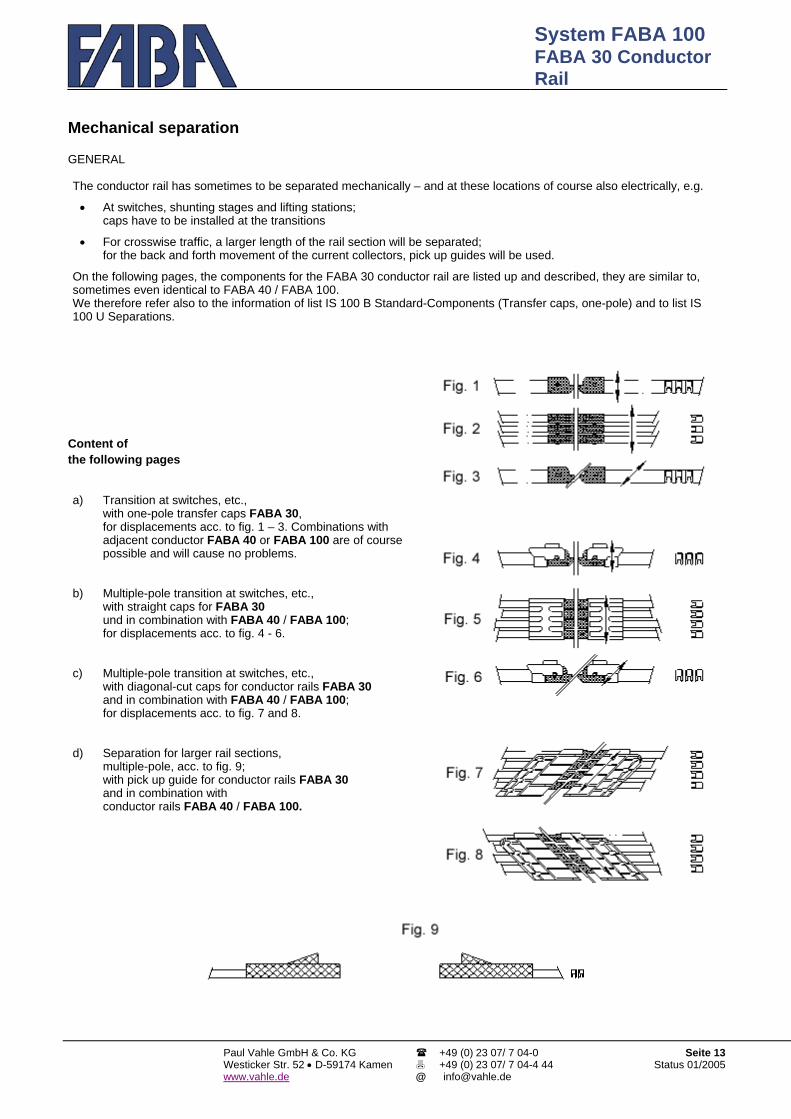
System FABA 100 FABA 30 Conductor Rail
Paul Vahle GmbH & Co. KG Westicker Str. 52 • D-59174 Kamenwww.vahle.de
+49 (0) 23 07/ 7 04-0 +49 (0) 23 07/ 7 04-4 44
Seite 13Status 01/2005
Mechanical separation GENERAL The conductor rail has sometimes to be separated mechanically – and at these locations of course also electrically, e.g. • At switches, shunting stages and lifting stations;
caps have to be installed at the transitions • For crosswise traffic, a larger length of the rail section will be separated;
for the back and forth movement of the current collectors, pick up guides will be used. On the following pages, the components for the FABA 30 conductor rail are listed up and described, they are similar to, sometimes even identical to FABA 40 / FABA 100. We therefore refer also to the information of list IS 100 B Standard-Components (Transfer caps, one-pole) and to list IS 100 U Separations.
Content of the following pages a) Transition at switches, etc.,
with one-pole transfer caps FABA 30, for displacements acc. to fig. 1 – 3. Combinations with adjacent conductor FABA 40 or FABA 100 are of course possible and will cause no problems.
b) Multiple-pole transition at switches, etc.,
with straight caps for FABA 30 und in combination with FABA 40 / FABA 100; for displacements acc. to fig. 4 - 6.
c) Multiple-pole transition at switches, etc.,
with diagonal-cut caps for conductor rails FABA 30 and in combination with FABA 40 / FABA 100; for displacements acc. to fig. 7 and 8.
d) Separation for larger rail sections,
multiple-pole, acc. to fig. 9; with pick up guide for conductor rails FABA 30 and in combination with conductor rails FABA 40 / FABA 100.

System FABA 100 FABA 30 Conductor Rail
Paul Vahle GmbH & Co. KG Westicker Str. 52 • D-59174 Kamenwww.vahle.de
+49 (0) 23 07/ 7 04-0 +49 (0) 23 07/ 7 04-4 44
Seite 14Status 01/2005
Mechanical separation – with one-pole transfer caps Permissible height/lateral displacement: ± 2 mm
Order No. Fig. Identification Weight241 017 160 1a + 2a Transfer cap without connecting cable Cap and plug in bag 0.006 241 017 167 1a + 2b without connecting cable Cap, plug, push-on sleeve in bag 0.008 241 017 168 1b + 2c without conn. cable, adjustable Cap, plug, push-on sleeve in bag 0.010
241 017 162 1a + 3 FABA 30 with connecting cable, 2.5 mm² Cap and connecting cable 1 m long 0.049 241 017 163 PE with connecting cable, 2.5 mm² in bag 0.042 241 017 164 Dat
a with connecting cable, 1.5 mm² (other lengths on request) 0.042
241 017 005 1a Transfer cap Plastic-red 0.004 241 017 167 1b Plastic-red 0.004
241 026 023 2a Plug Bronze; for cross sections of 1.5 mm² and 2.5 mm² Only 0.002 241 026 040 2b Bronze; with plug connection 6.3 x 0.8 If 0.003 241 026 042 2c Bronze; with plug connection 6.3 x 0.8 replaced 0.004
241 040 372 3 Connecting cable 2.5 mm² outer-∅ 4.5 1 kV black One-pole; halogenfree,
flexible; 0.045
241 040 373 1 m long 2.5 mm² outer-∅ 3.9 PE green-yellow (other lengths on request) 0.038 241 040 374 Data 1.5 mm² outer-∅ 5.1 grey 0.038
Technical information • Use: For separations on switches, etc., also as end cap at the end of the conductor rail – also for PE;
Conductor surface facing either down or sideways; for ambient temperatures: – 30 °C up to + 55 °C ; for conductor rail centre distances from 15 mm on; for travelling speeds up to 300 m/min.; in bends, if radius is at least 750 mm
• Design for data transfer: The connecting cabe is PVC-insulated with standard shielding, on request, we also deliver this type with HF-shielding (coaxial cable)
• The permissible height and/or lateral displacement of two opposite caps to one another is max. ± 2 mm Planning instructions • A prerequisite for a correctly functioning transition is a faultlessly operating switch
mechanism, even under load by a charged vehicle, for example. • One current collector per conductor rail is sufficient: the collector shoe bridges
both ends of the metal rails at the transition. • The PE-conductor rail can be positioned at any place of the system. • For switch displacement direction acc.to fig. 4 + 5
For switch displacement direction acc. to fig. 6 : perm. air gap = max. 5 mm, : perm. air gap = max. 3 mm.
• Hanger clamps are to be installed behind the caps: Distance between them: min. 100 mm, max. 200 mm
• The caps must not wander into the transition range, therefore, install fixing point clips as close as possible.
• Combinationen with adjacent conductor rails FABA 40 / FABA 100 may be realised at will: see transfer caps in list IS 100 U, page 3
Installation instructions • Insert plug – with or without cable – into the conductor rail end until end stop • Bend plug end – see arrow in fig. 7 • Open cap completely – both legs have to embrace the rail • Check of all transitions is necessary also during the displacement

System FABA 100 FABA 30 Conductor Rail
Paul Vahle GmbH & Co. KG Westicker Str. 52 • D-59174 Kamenwww.vahle.de
+49 (0) 23 07/ 7 04-0 +49 (0) 23 07/ 7 04-4 44
Seite 15Status 01/2005
Mechanical separation multiple-pole, with straight caps Permissible height/lateral displacement ± 2 mm
Note: Transitions are not complete, the additionally required caps FABA 30 acc. to the table below and for FABA 100 for separation IS 100 U, page 3. Order No. poles Identi- Single units in bags ; Weight
Assembly height 27
Assembly height 32
Assembly height 40
fication consisting of: BH 27
BH 32
BH 40
241 006 250 241 006 260 241 006 270 4- Fig. 1 Bracket plastic-orange = 1 piece 0.038 0.046 0.050241 006 251 241 006 261 241 006 271 5- Fig. 2 Compensation plate - orange 0.042 0.051 0.057241 006 252 241 006 262 241 006 272 6- AH 27 = without ; 0.046 0.056 0.064241 006 253 241 006 263 241 006 273 7- AH 32 = 1 piece 5 thick ; 0.050 0.061 0.071
AH 40 = 1 piece 13 thick 241 006 254 241 006 264 241 006 274 8- Trans- Fig. 3 Screw with nut, washer, 0.054 0.066 0.078241 006 255 241 006 265 241 006 275 9- ition lock washer up to 9-pol. = 2 pieces, 0.058 0.071 0.085241 006 280 241 006 290 241 006 300 10- from 10-pol. = 3 pieces 0.072 0.086 0.102241 006 281 241 006 291 241 006 301 11- FABA AH 27 = M5 x 10, AH 32 = M5 x 14, 0.076 0.091 0.109
30/100 AH 40 = M5 x 22 241 006 282 241 006 292 241 006 302 12- 0.080 0.096 0.116241 006 283 241 006 293 241 006 303 13- Fig. 4 Distance plate plastic-orange 0.084 0.101 0.123241 006 284 241 006 294 241 006 304 14- 1 piece each, 1 mm and 2 mm thick 0.088 0.106 0.130
Order No. Fig. Identification Weight
241 017 160 5a + 6a Cap w. crimping plug 0.006 FABA 30
241 017 167 5a + 6b w. plug connection Cap plastic-red, plug 6.3 x 0.8 + socket in bag 241 017 168 5b + 6c w. plug connection Cap plastic-red, plug 6.3 x 0.8 + socket in bag
241 017 162 5a with Cable 2.5 mm² Außen-∅ 4.5 1 kV black One-pole, halogenfree, flexible; 0.049 241 017 163 and cable 2.5 mm² Outer-∅ 3.9 PE
green/yellow one-side with plug 0.042
241 017 164 7 1 m long 1.5 mm² Outer-∅ 5.1 Data grey (other lengths on request) 0.038
241 046 030 without Drilling jig for even no. of poles for electric monorails 0.820 241 046 080 Fig. Drilling jig für odd no. of poles 180 x 60 0.700 241 024 052 4 Distance plate 15 pieces each, 1 mm and 2 mm thick ; plastic-orange ; in bag 0.042
518 505 062 8 Screw driver SW 3 for hexagon socket screw M5 0.030

System FABA 100 FABA 30 Conductor Rail
Paul Vahle GmbH & Co. KG Westicker Str. 52 • D-59174 Kamenwww.vahle.de
+49 (0) 23 07/ 7 04-0 +49 (0) 23 07/ 7 04-4 44
Seite 16Status 01/2005
Mechanical separation multiple-pole, with straight caps – Continuation - Permissible height/lateral displacement: ± 2 mm Technical Information • Use for separations on switches, etc.;
conductor surface facing either down or sideways; multiple-pole – conductor rail centre distance:15 mm; for ambient temperatures of - 30 °C up to + 55 °C ; for travelling speeds up to 300 m/min.; in bends, when radius is at least 750 mm
• Design for data transfer the connecting cable is PVC-insulated with standard shielding, on request, we also deliver this type with HF-shielding (coaxial cable).
• Permissible height and/or lateral displacement of two opposite caps to one another: max. ± 2 mm
Planning instructions • Prerequisite: for a correctly functioning transition is a faultlessly operating mechanical (switch) system
even under load e.g. by a charged monorail vehicle • One current collector is sufficient per conductor rail: the collector shoe briges both ends of the metal rails at the transition. • The PE-conductor rail may be positioned at any place of the system. • For switch displacement acc. to fig. 8 + 9
For switch displacement acc. to fig. 10 : Perm. air gap E = max. 5 mm, : Perm. air gap F = max. 3 mm.
• These transitions arrest the conductor rail in the lengthwise direction, thus, these are „fixed points“ with the advantage of maintaining the correctly adjusted transition air gap.
• Conductor rail-combinations of FABA 30 with FABA 100 can be realised at will, please combine:
Transition consisting of bracket, compensation plate, screws and distance plate (consider the assembly height and the no. of poles), see IS 100 C, page 14
Caps for conductor rails FABA 30 see list IS 100 C, page 14 for conductor rails FABA 100 see list IS 100 U, page 3 with or without connecting cable
• The distance plates of fig. 4 ensure the correct transition from cap to cap, if necessary.
Installation instructions • Drill conductor rail or traversing rail „C“ (use drilling jig, A1 = Bracket if nec.), up to 9-poles per transition = 2 holes, A2 = Compens. plate for assembly height 27 = without from 10 poles = 3 holes, for sizes see fig. 8 + 9 for assembly height 32 = 5 thick • Insert square nuts into the slits of the bracket for assembly height 40 = 13 thick • Attach distance parts for assembly heights 32 and 40 B = Assembly height 27 or 32 or 40 • Loosely screw down bracket – without caps C = Monorail-running rail or other traversing rail • Prepare all transitions in the same way D = Direction of displacement • Shorten conductor rails – and also all bends – to the exact E = Fig. 8 and 9 tranisition-air gap: length, de-burr them thoroughly, also the inner surfaces max. 5 mm between the caps • For FABA 40 / 100 see separation F = Fig. 10 transition-air gap: IS 100 U, page 3 max. 3 mm between the caps
• For FABA 30: mount cap of fig. 5a to fig. 11: Fastening dimensions Insert plug of fig.6a or 6b or cable with plug of fig. 7 Fig. 8 and 9: x = 28 ± 5 or 55 ± 5 (optional) into the rail and bend it into the direction of the arrow. Fig. 10 for a displacement of 45°: Push cap on the conductor rail Assembly height 27: Y = 50 ± 5; Z = 38 ± 5 Assembly height 32: Y = 55 ± 5; Z = 33 ± 5 • For FABA 30: mount cap of fig. 5b to fig. 12: Assembly height 40: Y = 63 ± 5; Z = 25 ± 5 Insert plug of fig. 6c – with or without connecting cable - until the end of the cap. ∅ = drill hole in″C″: Assembly height 27 = 7.2 + 0.3 Push them both together on the conductor rail. Assembly height 32 = 5.0 + 0.5 Press cap until it engages Assembly height 40 = 5.0 + 0.5 • All caps must always embrace both sides of the conductor rail • Clip the conductor rails – with the caps mounted – into the brackets, both sides of the conductor rail have to be embraced. • Align caps exactly to the transition air gap: In particular, the caps of fig. 12 can be adjusted by 3 mm. • Screw down tightly the bracket to the running rail/traversing rail • Check of all transitions is necessary also during the displacement. • In case of uneven heights from cap to cap, insert, if necessary, distance plates acc. to fig. 4 at the screws to the running rail.

System FABA 100 FABA 30 Conductor Rail
Paul Vahle GmbH & Co. KG Westicker Str. 52 • D-59174 Kamenwww.vahle.de
+49 (0) 23 07/ 7 04-0 +49 (0) 23 07/ 7 04-4 44
Seite 17Status 01/2005
Mechanical separation multiple-pole, 45°
ABC DE F
Conductor rail transition complete Assembly height 32 or 40 Electric suspended monorail or other trav.rail Direction of displacement Transition air gap max. 3 mm betw. the caps Conductor rail FABA 30
Fastening dimensions: x = 48 ± 3 mm ∅ = Drill hole in ″C″ = 5.5 + 0.5 mm
Technical information • The transitions left and right of 45° – cut angle for switches, for example
are identical to the transitions for conductor rails FABA 40 / 100 • Refer to our list „Separations“ IS 100 U, pages 8 and 9 • Moreover, the following has to be taken into consideration:
The transitions may be used for all conductor rail types FABA 30, FABA 40 and FABA 100, even for any kind of combination, however, the supplied plug cannot be used for FABA 30
Planning instructions • Refer to our list „Separations“ IS 100 U, page 9 • Moreover, the following has to be taken into consideration:
- combinations of FABA 30 with FABA 40 or FABA 100 in any order may be realised - for conductor rail FABA 30, the supplied plug cannot be used - thus, no power feeds for the 45° separation
Installation instructions • Refer to our list „Separations“ IS 100 U, page 9 • The following has to be considered when connecting the conductor rail FABA 30:
- the conductor rails FABA 30 will fit into the transfer caps - the supplied plug cannot be used - thus, no power feed will be possible

System FABA 100 FABA 30 Conductor Rail
Paul Vahle GmbH & Co. KG Westicker Str. 52 • D-59174 Kamenwww.vahle.de
+49 (0) 23 07/ 7 04-0 +49 (0) 23 07/ 7 04-4 44
Seite 18Status 01/2005
Mechanical separation Pick up guide
A = Conductor rail FABA 30 or FABA 40 or FABA 100 A1 = Separation between the metal rails, length depends on the system. B = Hanger clamp: one or multiple-pole, assembly heights on request. C = Electrical separation FABA 30, see IS 100 C, page 10
FABA 40 / 100 see IS 100 B page 18 D = Multipole pick up guide: suitable for all parallel arm current collectors.
Technical information • The separation shown is identical to the separation for conductor rails FABA 40 / 100 • Refer to our list ″ IS 100 U pages 10 and 11 • Moreover, the following has to be taken into consideration:
the pick up guides can be used for all conductor rail types FABA 30, FABA 40 and FABA 100 and for each kind of combination
• The current collector has to pass the pick up guide without current, otherwise an arc will form at the separation point due to the ionisation with the air.
Planning instructions • Refer to our list „Separations“ IS 100 U, page 10 • The following has to be considered: Combinations of FABA 30 with FABA 40 or FABA 100 in any order can be realised • If a continuous power supply is required, at least two current collectors per conductor rail must be planned.
Installation instructions • Refer to our list „Separations“ IS 100 U, page 11

System FABA 100 FABA 30 Conductor Rail
Paul Vahle GmbH & Co. KG Westicker Str. 52 • D-59174 Kamenwww.vahle.de
+49 (0) 23 07/ 7 04-0 +49 (0) 23 07/ 7 04-4 44
Seite 19Status 01/2005
Current collectors For our conductor rail FABA 30 all current collectors of the system FABA 100 are suitable – see list IS 100 B Standard-Components -, i.e. the same current collectors have to be planned which are also required for the combinations with adjacent conductor rails FABA 40 / FABA 100. For systems with pick up guides, plan parallel arm current collectors only. In case of the connecting cables, you have of course to differentiate if the current collectors are used for power transmission, for control purposes or for the electronic data transfer.
Data transfer The conductor rail FABA 30 is suitable, due to its reasonable price, both for the transfer of electronic information/data and for the transfer of control signals. Please consider that both the lines of the feeding components and the connecting cables of the current collectors have to be shielded. The cables are indicated in this list with the corresponding components.
Pre-assembled conductor rail system In list IS 100 V, we would like to present our advanced system: The conductor rails FABA 40 / FABA 100 are completely assembled to the supporting, and running rails (e.g. for the electric monorail) with all accessory in the factory and transported to the location where their use is required. If for this use (or exclusively) , the FABA 30 conductor rail is planned, please contact us for further information
Apart from a good planning of the conductor rail system, a correct and orderly installation is indispensable for the reliable operation and this not only for standard installations but also for extensively branched circuits – or for high travelling speeds, extreme fluctuations of temperature, etc.
Please, do not hesitate to contact us, if you need our assistance; Our experienced field agents are looking forward to supporting you with their long-standing experience.
For the realisation of the assembly work, we recommend to ask for our trained technicians – also to ensure the guarantee.
You can now rely on a partner with knowledge, competence and a long-standing experience.

System FABA 100Data Transfer
Paul Vahle GmbH & Co. KG Westicker Str. 52 • D-59174 Kamen www.vahle.de
+49 (0) 23 07/ 7 04-0 +49 (0) 23 07/ 7 04-4 44
Seite 1Status 01/2005
Data Transfer
Conductor Rail System FABA 100
for mobile equipment

System FABA 100Data Transfer
Paul Vahle GmbH & Co. KG Westicker Str. 52 • D-59174 Kamenwww.vahle.de
+49 (0) 23 07/ 7 04-0 +49 (0) 23 07/ 7 04-4 44
Seite 2Status 01/2005
Introduction Our FABA 100 conductor rail system is not only suitable for the transmission of electrical energy but data may certainly be transmitted also; where one has to differentiate between the type of "data". 1. For simple tasks such as the transmission of signals to the mobile equipment, e.g. to trigger control commands, the
arrangement of electric or galvanic separation points within the conductor rail system is generally sufficient. The separating points are located in specially installed conducting rails - i.e. beside those required for the power transmission - they are to be equipped as simple electric interruption or with a separately fed rail section for example. Such separating points can be installed with our FABA 100 system without any problems at practically any point of the installation - also quite easy to be altered for different tasks. These electric separations may also be utilized for outdoor installations. All conductor rails - also the FABA 40 steel - can be used. As a rule current collectors with copper containing collector shoes are suitable for data transfer. One current collector is sufficient for the transmission of control commands. Please use standard components for this purpose according to list IS 100 B.
2. In the course of the automation- and material-flow technique informations / data are to be transferred from a
stationary computer via the conductor rail to a mobile data station. This certainly places the highest demands on the conductor rail system.
Now and then, even today, we meet with the prejudice that the transfer of data via conducting rails is "not to be
achieved" with the assumption that misses. interruptions and other disturbances may occur and place doubts on its proper functioning.
However, we have been able - and that for many years - to prove under real conditions that the transfer of data
with our conductor rail system is carried out without any faults.
Insulated-Conductor-Rail System FABA 100
For the transmission of electric power and data to mobile equipment : * For flawless bit-by-bit data transfer from stop to a traveling speed of 20 m/sec * For the passing of multiplex data without time delay (real-time-transfer) * For the transfer of signals from incremental and absolute path-measuring-systems * For the passing of sensor-signals and control parameters * Switches and branches can be realized * Several operating devices or machines on the same installation may be supplied simutaneously with data by the
appropriate number of conductor rails * It is possible to transfer data during unidirectional traffic as well as during the reversing operation * Use only in dry indoor spaces * Application of the components : refer to this list "Selection of Components" * e.g.for Control units for shelves , electric monorails , handling equipment , mobile robots , crane
Installations ,automated assembly lines Based on our substantial experience we find the specific solution for every application. We don't just recommend the listed components but develop and deliver individual components if required. Our customers both at home and abroad value this service and our search for the optimized solution. Our specialists are happy to be available for a personal meeting to discuss your requirements.
FABA – a product of VAHLE

System FABA 100Data Transfer
Paul Vahle GmbH & Co. KG Westicker Str. 52 • D-59174 Kamenwww.vahle.de
+49 (0) 23 07/ 7 04-0 +49 (0) 23 07/ 7 04-4 44
Seite 3Status 01/2005
General • The installation or layout and the selection of all FABA-components has to be planned very carefully. • Correct installation is a prerequisite for a proper function –especially if high traveling speeds are planned.
Data transfer in the sense of this list can only take place in dry indoor spaces. • Provide only for a conductor rail center separation of 15 mm. • Arrangement of the conductor surface facing down or sideways. • Back and forth operation is possible. • Permissible ambient temperatures – 30 °C to + 80 °C. • Installations may also be equipped with pick up guides, i.e. with larger mechanical separations - refer to our
list IS 100 U. Location of the Conductor rail system Fig. 1 Example 8 poles : Fig.2 Example 9 poles: Power transmission and data transfer Power transmission without shielding without shielding Data transfer with shielding
Fig. 3 Shielding : Connect the shielding of the conductor rail fed cables as well as the current collector connection cables with the cable AL so that they are electrically at the same potential. The conductor rail feed cable AL is to be Connected in accordance with the valid national regulations.
Legend A Conductor rai corresponding to list IS 100 B : • for power transmission choice FABA 40 or FABA 100 • for data transfer = FABA 100 - i.e. with copper metal rail B Fig. 1 Conductor rail feed cable : • for power transmission = corresponding to list IS 100 B - without shielding • for data transfer = corresponding to list IS 100 B - without shielding - 1.5 mmý is sufficient C Fig. 2 Conductor rail feed cable : • for power transmission = corresponding to list IS 100 B - without shielding • for data transfer = with shielding, refer to "Selection of Components" in this list D Current collector : • for power transmission = with copper carbon collector shoe • for data transfer = with silver carbon collector shoe E Fig. 1 Current collector connecting cable : • for power transmission and data transfer - without shielding F Fig. 2 Current collector connecting cable : • for power transmission = without shielding • for data transfer = with shielding "grey"
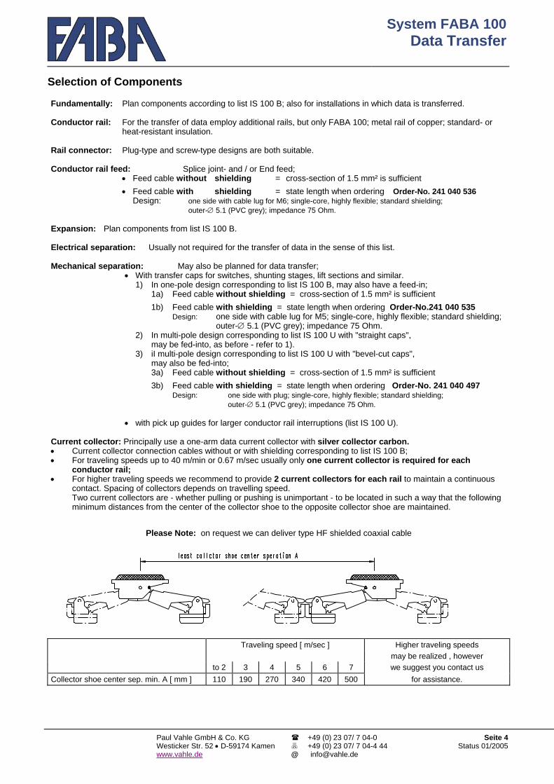
System FABA 100Data Transfer
Paul Vahle GmbH & Co. KG Westicker Str. 52 • D-59174 Kamenwww.vahle.de
+49 (0) 23 07/ 7 04-0 +49 (0) 23 07/ 7 04-4 44
Seite 4Status 01/2005
Selection of Components Fundamentally: Plan components according to list IS 100 B; also for installations in which data is transferred. Conductor rail:
For the transfer of data employ additional rails, but only FABA 100; metal rail of copper; standard- or heat-resistant insulation.
Rail connector: Plug-type and screw-type designs are both suitable. Conductor rail feed: Splice joint- and / or End feed; • Feed cable without shielding = cross-section of 1.5 mm² is sufficient • Feed cable with shielding = state length when ordering Order-No. 241 040 536 Design:
one side with cable lug for M6; single-core, highly flexible; standard shielding; outer-∅ 5.1 (PVC grey); impedance 75 Ohm.
Expansion: Plan components from list IS 100 B. Electrical separation: Usually not required for the transfer of data in the sense of this list. Mechanical separation: May also be planned for data transfer; • With transfer caps for switches, shunting stages, lift sections and similar. 1) In one-pole design corresponding to list IS 100 B, may also have a feed-in; 1a) Feed cable without shielding = cross-section of 1.5 mm² is sufficient 1b) Feed cable with shielding = state length when ordering Order-No.241 040 535 Design: one side with cable lug for M5; single-core, highly flexible; standard shielding;
outer-∅ 5.1 (PVC grey); impedance 75 Ohm. 2) In multi-pole design corresponding to list IS 100 U with "straight caps",
may be fed-into, as before - refer to 1). 3) iI multi-pole design corresponding to list IS 100 U with "bevel-cut caps",
may also be fed-into; 3a) Feed cable without shielding = cross-section of 1.5 mm² is sufficient 3b) Feed cable with shielding = state length when ordering Order-No. 241 040 497 Design:
one side with plug; single-core, highly flexible; standard shielding; outer-∅ 5.1 (PVC grey); impedance 75 Ohm.
• with pick up guides for larger conductor rail interruptions (list IS 100 U). Current collector: Principally use a one-arm data current collector with silver collector carbon. • Current collector connection cables without or with shielding corresponding to list IS 100 B; • For traveling speeds up to 40 m/min or 0.67 m/sec usually only one current collector is required for each
conductor rail; • For higher traveling speeds we recommend to provide 2 current collectors for each rail to maintain a continuous
contact. Spacing of collectors depends on travelling speed. Two current collectors are - whether pulling or pushing is unimportant - to be located in such a way that the following minimum distances from the center of the collector shoe to the opposite collector shoe are maintained.
Please Note: on request we can deliver type HF shielded coaxial cable
Traveling speed [ m/sec ] Higher traveling speeds may be realized , however to 2 3 4 5 6 7 we suggest you contact us Collector shoe center sep. min. A [ mm ] 110 190 270 340 420 500 for assistance.

System FABA 100Hanger Clamps
Paul Vahle GmbH & Co. KG Westicker Str. 52 • D-59174 Kamen www.vahle.de
+49 (0) 23 07/ 7 04-0 +49 (0) 23 07/ 7 04-4 44
Seite 1Status 01/2005
Hanger Clamps
Conductor Rail System FABA 100
for mobile equipment

System FABA 100Hanger Clamps
Paul Vahle GmbH & Co. KG Westicker Str. 52 • D-59174 Kamenwww.vahle.de
+49 (0) 23 07/ 7 04-0 +49 (0) 23 07/ 7 04-4 44
Seite 2Status 01/2005
General
Hanger clamps serve to fasten the conductor rails to a beam. Screw-type hanger clamps for general use are listed under components IS 100 B. Beyond that we have developed further hanger clamps for the most diverse applications, most of which are kept in stock, they are shown in this list.
Technical Information Valid for all hanger clamps shown in this list- unless stated otherwise : • Body of clamp one unit, made of polycarbonate plastic, colour orange. • For conductor rail centre separation 15 mm. • Permissible ambient temperatures - 30°C to + 80°C. • The clipped-in conductor rails slide in the hanger clamps allowing expansion in length. • Important : Hanger clamps with adhesive tape can only be stored for approx. 1½ years. • The hanger clamps shown in this list have largely been developed for special profiles of various electric monorails, -
for the most part they are clipped-in. We forego to state detailed measurements because the perfect fit can only be determined with an original profile. For this reason we require a sample of unknown profiles, we can supply you with a sample clamp if requested.
Planning Instructions • The assembly height has to be observed at al times. • For assembly heights of 32 mm or more, control cables can be installed through openings in the hanger clamps. • The rails (ground) may be located at arbitrary points. • Hanger distances : In straight sections max. 800 mm, in bends max. 400 mm; to the ends of the conductor rails
min. 100 mm, max. 300 mm, also refer to the basic diagram of list IS 100 B. Installation Instructions • Depending on the installation, the hanger clamps are fastened directly or by means of consoles to the track / rail;
they have to align correctly. • The conductor rails are simply pressed into the hanger clamps until they audibly snap-in. • The conductor rail can be taken out of the hanger clamp at any time :
Push the sides of the clamp apart ; for extensive installations we recommend to use the rail removal wedge – refer to list IS 100 B = hanger clamps.
Structure of the list Hanger clamps screw-type, assembly height 27 mm assembly height 32 mm assembly height 40 mm clip-type , assembly height 27 mm assembly height 32 mm assembly height 40 mm others , assembly height 27 mm assembly height 32 mm assembly height 40 mm Fastenings
FABA – a product of VAHLE

System FABA 100Hanger Clamps
Paul Vahle GmbH & Co. KG Westicker Str. 52 • D-59174 Kamenwww.vahle.de
+49 (0) 23 07/ 7 04-0 +49 (0) 23 07/ 7 04-4 44
Seite 3Status 01/2005
Hanger-Clamp screw-type assembly
Order-No. Weight 241 006 138 2-poles 0,008 241 006 129 3-poles 0,012 241 006 128 4-poles 0,015 241 006 127 5-poles 0,019 241 006 137 6-poles 0,023 241 006 126 7-poles Fig. Height 0,026 241 006 130 8-poles 1 27 mm 0,030 241 006 131 9-poles 0,034 241 006 132 10-poles 0,038 241 006 133 11-poles 0,042 241 006 134 12-poles 0,045 241 006 135 13-poles 0,049 241 006 136 14-poles 0,053
Order-No. Weight
241 009 211 2-poles 0,006 241 009 212 3-poles 0,009 241 009 213 4-poles 0,012 241 009 214 5-poles 0,015 241 009 215 6-poles 0,018 241 009 216 7-poles Fig. Height 0,021 241 009 217 8-poles 2 32 mm 0,024 241 009 218 9-poles 0,027 241 009 219 10-poles 0,030 241 009 220 11-poles 0,033 241 009 210 12-poles 0,036
Order-No. Weight
241 006 017 8-poles Fig. Height 0,030 3 32 mm
Order-No. Weight.
241 009 223 4-poles 0,020 241 009 224 5-poles Fig. Height 0,025 241 009 225 6-poles 4 40 mm 0,030 241 009 226 7-poles 0,035 241 009 227 8-poles 0,040
Order-No. Fig. Weight 241 013 003 5 Screw Set M6 x 25 für clamp fig. 1 with washer orange, spring
washer and nut; set; zinc-plated, in bag
0,010
241 013 001 6 Screw Set M6 x 20 for clamp fig. 3+4 with spring washer and nut; set; zinc-plated, in bag
0,008
241 013 022 Screw Set M6 x 12 0,008 241 013 023 7 Screw Set M6 x 16 for clamp fig. 2 0,009 241 013 024 Screw Set M6 x 20
with washer, spring washer and plate with thread hole
set; zinc-plated, in bag
0,010
Technical Information a) Permissible continuous ambient temperatures:
- 30 °C to + 80 °C. b) Center separation 15 mm.
Hanger clamps are delivered without screw material. If M6 accessories are required, we request you to inform us about the type. The number of screw connections depends on the type of hanger clamp and the number of poles. The drawings show examples of screw-fastenings.

System FABA 100Hanger Clamps
Paul Vahle GmbH & Co. KG Westicker Str. 52 • D-59174 Kamenwww.vahle.de
+49 (0) 23 07/ 7 04-0 +49 (0) 23 07/ 7 04-4 44
Seite 4Status 01/2005
Hanger - Clamp Clip-type - Assembly height 27 mm Technical Information All hanger clamps are precisely matched to the AMS-profile ; the backsides are provided with a durable adhesive strip at the factory , to prevent lateral slip in the AMS-profile (AMS = Automated Monorail System). Hanger clamps with adhesive strip can only be stored for max. 1 ½ years.

System FABA 100Hanger Clamps
Paul Vahle GmbH & Co. KG Westicker Str. 52 • D-59174 Kamenwww.vahle.de
+49 (0) 23 07/ 7 04-0 +49 (0) 23 07/ 7 04-4 44
Seite 5Status 01/2005
Hanger - Clamp Clip-type - Assembly height 32 mm
Technical Information All hanger clamps are precisely matched to the AMS-profile ; the backsides are provided with a durable adhesive strip at The factory , to prevent lateral slip in the AMS-profile (AMS = Automated Monorail System). Hanger clamps with adhesive tap can only be stored for max. 1 ½ years.

System FABA 100Hanger Clamps
Paul Vahle GmbH & Co. KG Westicker Str. 52 • D-59174 Kamenwww.vahle.de
+49 (0) 23 07/ 7 04-0 +49 (0) 23 07/ 7 04-4 44
Seite 6Status 01/2005
Hanger - Clamp Clip-type - Assembly height 40 mm
Technical Information All hanger clamps are precisely matched to the AMS-profile ; the backsides are provided with a durable adhesive strip at The factory , to prevent lateral slip in the AMS-profile (AMS = Automated Monorail System). Hanger clamps with adhesive tap can only be stored for max. 1 ½ years.

System FABA 100Hanger Clamps
Paul Vahle GmbH & Co. KG Westicker Str. 52 • D-59174 Kamenwww.vahle.de
+49 (0) 23 07/ 7 04-0 +49 (0) 23 07/ 7 04-4 44
Seite 7Status 01/2005
Hanger – clamp Stud – mounting with spring clip Technical Information The hanger clamps are fastened with their bolts to the AMS-rail-web by means of spring clips. (except order no. 241 006 005)

System FABA 100Hanger Clamps
Paul Vahle GmbH & Co. KG Westicker Str. 52 • D-59174 Kamenwww.vahle.de
+49 (0) 23 07/ 7 04-0 +49 (0) 23 07/ 7 04-4 44
Seite 8Status 01/2005
Fastening-Consoles
In the following a few consoles out of our program : The sketches also as an inspiration on how the fastening of hanger clamps may eventually be solved in a similar manner. Shown are the hanger clamps for the insertion- /quick-mounting, the screw-types -depending on local conditions - may be employed in a similar way . We are certainly prepared to develop new consoles to specifications , feel free to ask us .
Fig. 1 Fastening with solid sheet-metal console for quick installation ; Hanger-clamp e.g. 4 poles Art.-No. 241 003 601
Fig. 2 Fastening with a plastic console screwed to a girder ; Hanger clamp e.g. 6 poles
Fig. 3 Fastening with Al –cast console clamped to a girder
Hanger clamp e.g. 6 poles
Fig. 4 Fastening with Al –cast console clamped to a traverse
Hanger clamp e.g. 8 poles

System FABA 100 Checking Devices
Paul Vahle GmbH & Co. KG Westicker Str. 52 • D-59174 Kamenwww.vahle.de
+49 (0) 23 07/ 7 04-0 +49 (0) 23 07/ 7 04-4 44
Seite 1Status 01/2005
Checking Devices
Conductor Rail System FABA 100
for mobile equipment

System FABA 100 Checking Devices
Paul Vahle GmbH & Co. KG Westicker Str. 52 • D-59174 Kamenwww.vahle.de
+49 (0) 23 07/ 7 04-0 +49 (0) 23 07/ 7 04-4 44
Seite 2Status 01/2005
Introduction
Basically, the collector shoes of the different current collectors of our system are designed as a single replaceable component part – they are subject to wear. This wear is different from installation to installation, since it is caused by a variety of influences, e.g. the existing ambient temperatures, additional heat caused by the energy transfer at the conductor rail, atmospheric humidity, travelling speeds, the frequency of „stop and go“, the number and kind of curves and bends to be travelled, the number of conductor rail interruptions like expansion points, electrical separations, switches, lifting devices etc. Therefore, it might absolutely be possible that even within an individual installation, the collector shoes – e.g. at the individual running gears in case of an electric suspended rail – are differently worn. Even at the same running gear, the collector shoes may indicate a different wear as PE-current collectors do not need to pass electrical interruptions. As you may understand, indications concerning „Stop intervals/travelling performances“ of our collector shoes cannot be made due to the aforementioned reasons. A very global standard value may be, according to our experience, 15.000 – 20.000 km. However, it has to be taken into consideration that the collector shoes are more intensely worn during the start phase in case of a new installation, than later when the metal rail has become smoother and the splices/transitions are more run in and furthermore, a certain – frequently favourable – layer of patina has formed on the collector surface.
In order to prevent a standstill due to worn or broken collector shoes, they have to be inspected:
a) Continuous manual inspections and a „registration“, if necessary, of each single collector shoe is often not very
economical and frequently leads to the unacceptable safety measure of „collector shoe replacement“ although the limit of wear is not reached by far. However, manual inspections do not exclude the fault that malfunctions caused by worn collector shoes will occur. Such malfunctions will not only lead to unpleasant standstills but they may also have a negative impact on the collector surface of the conductor rails as in case of an insufficient power transmission heat damages may be caused. If this is the case, the collector surfaces of the complete system will have to be verified and the damages will have to be eliminated, as, even by using new collector shoes, a sufficient power transmission cannot be ensured, at least, an accelerated wear of the collector shoes will have to be expected. It is, however, possible to do without complicated manual inspections!
b) We offer automatic checking and inspection devices.
If the collector shoe passes such a checking device or station, the state of the collector shoe will be automatically and reliably checked and monitored, manual inspections will be no longer necessary. Unacceptably worn or broken collector shoes or the fleece of the cleaning shoe are recognised by the device and will be immediately indicated. This indication can be interpreted in different ways, e.g. by switching off the subsequent section in case of simple systems, by activating the subsequent switch in case of branched systems, which are usual for the electric suspended monorail, which puts the vehicle out of operation. In general, one checking device per system will be sufficient, if it is ensured that all vehicles/collector shoes are monitored as often as possible.
FABA – a product of VAHLE

System FABA 100 Checking Devices
Paul Vahle GmbH & Co. KG Westicker Str. 52 • D-59174 Kamenwww.vahle.de
+49 (0) 23 07/ 7 04-0 +49 (0) 23 07/ 7 04-4 44
Seite 3Status 01/2005
Collector shoe wearing tester
Order No.
This testing device to verify the wear of the collector shoe will only be fabricated individually according to the local conditions of use.
To be supplied on In your request, please state the
following:
request only • Which current collectors are used? • How is the conductor rail center distance (usually 15 mm)? • Which hanger clamp is used for your system or how is the assembly height? • In case of an electric monorail, please specify the form of the monorail • If it is not an electric monorail: Which fastenings are used or should be used? • No. of poles that are to be monitored? • Length of the connecting cable (usually 2 m) Working mode At the control point, the plunger, clipped on the continuous conductor rail, will be mechanically lifted by the passing current collector head. The more the carbon of the collector shoe is worn, the more the plunger will be lifted. If a specified value is exceeded, i.e. if the collector shoe is worn to the permissible extent, the microswitch responds and will guide, e.g. for the control of a switch, to a by-pass section.
The cleaning shoes are monitored in the same way. A = Continuous conductor rail B = Collector shoe The adjacent figure shows the basic structrure. C = Head of the current collector The installation of one plunger on each of the adjacent conductor rails can be selected.
D = Clamp for the conductor rail(s)
We recommend the monitoring of all current collectors, as the wear on the individual rails
E = Plunger; 1 piece per pole / conductor rail;
may differ considerably. will be lifted by C and will then spring back into its original position F = Fastening: e.g. conductor rail web of the
electric monorail; with recess and fastening holes This mechanically/electrically operating wear testing device for the collector shoes has a trouble free function with one moving part.
G = Switch plate, adjustable, 1 microswitch
After a correct assembly, it works reliably and can per pole / conductor rail easily be maintained. H = Connecting cable; 2m long, firmly connected
2 x 0.75 mm², H03VV - F für 230 Volt

System FABA 100 Checking Devices
Paul Vahle GmbH & Co. KG Westicker Str. 52 • D-59174 Kamenwww.vahle.de
+49 (0) 23 07/ 7 04-0 +49 (0) 23 07/ 7 04-4 44
Seite 4Status 01/2005
Collector shoe wearing tester Continuation Technical information • The collector shoe wearing tester is basically suitable for all listed current collectors (including cleaning shoes) • The switches including the corresponding wiring has the system of protection IP 4X, i.e. it is only suitable for dry
interior spaces • The permissible ambient temperatures are - 30 °C up to + 70 °C, i.e this means a slight deviation compared to the
heat-resistant insulation • The testing device and our standard components are of equal chemical resistivity • Suitable for travelling speeds up to 75 m/min., and back and forth operations • Suitable for conductor surfaces facing down or sideways
Planning instructions • In general, one collector shoe wearing tester per system will be sufficient, if possible, directly preceding a by-
pass/maintenance section, at a point which will be passed by the current collectors. If one of the microswitches reacts, e.g. the switch to the maintenance section can be controlled and the vehicle can be separated.
• •
In case of an electric monorail, the testing device is fastened to the web of the running rail. On one side, the conductor rails and the probe are clipped on and on the opposite side, the switch plate is screwed down. The switches scan the probes through a relatively large recess (please consider that a possible weakening of the monorail may occur). The conductor rails slide in the control station, therefore, the distance to the rail connector, etc. must be min. 100 mm
Installation instructions • •
Each testing device will be supplied with exact instructions for cut-out dimensions and installation procedure if required A correct assembly is indispensable for a reliable operation of the testing device.
Maintenance •
The functioning of the testing device must be regularly checked: In particular, the movability of the plungers, they must not be tilted or get jammed! Do the springs which press back the plunger work properly? Do the microswitches work properly?
• •
A contamination has to be avoided. We recommend the use of a cleaning aggregate, refer to special list IS 100 S Clean using air pressure nose

System FABA 100Dust Removal
Paul Vahle GmbH & Co. KG Westicker Str. 52 • D-59174 Kamenwww.vahle.de
+49 (0) 23 07/ 7 04-0 +49 (0) 23 07/ 7 04-4 44
Seite 1Status 01/2005
Dust Removal
Conductor Rail System FABA 100
for mobile equipment
System FABA 100Dust Removal
Paul Vahle GmbH & Co. KG Westicker Str. 52 • D-59174 Kamenwww.vahle.de
+49 (0) 23 07/ 7 04-0 +49 (0) 23 07/ 7 04-4 44
Seite 2Status 01/2005
Introduction
Dust collecting over a period of time - even though our plastic components are largely antistatic - make the system comparably unsightly, i.e. the orange signal color looses its brilliance, which, in general, does not influence the quality of the conductor rail system. One has to distinguish between system- and externally generated dusts.
Dusts generated by the system are those caused by the wear of the collector shoes.
The collector shoes of the current collectors contain a large amount of copper or silver, as for the case of data transfer. However, they contain an appreciable amount of graphite, which is released during the wearing process and advantageously collecting in form of a patina on the surface of the conductor, reducing the friction, as well as graphite particles being raised by the moving current collectors or vehicles and subsequently being deposited on various components. It often comes to pronounced deposits of graphite especially at mechanical interruptions of the conductor rails (expansion points, separation- and transfer caps). This blackening of the components must not be a cause for alarm, - apart from the optics - it does not negatively affect the technique of the conductor rail system.
Externally generated dusts are those generated outside the conductor rail system - mostly through production
processes. As floating particles they deposit themselves on the FABA-system, and are partly blown up again by the wind of moving equipment (e.g. AMS) and can in time be distributed throughout the complete system. Since these dusts are of different sizes and may consist out of the most diverse materials, It has to be determined in the individual case whether detrimental effects to the conductor rail system are to be expected; usually, dusts generated by the system, do not have a negative effect on the technical components. However, harmful dusts do indeed exist; from our experience over many years we name in particular:
a) unusually strong emissions, b) if they are also very conductive and c) if they are fibrous, perhaps even relatively long. Especially the dusts mentioned under c) may be very light, thus may be raised quite easely; they deposit themselves
also on the conductor surface, for example, and - since they are mostly non-conductive – lead to contact problems. It has to be mentioned that the dusts generated by the system as well as the dusts from external sources, depending on the type of operation and intensity, may be detrimental : a) to the personnel, b) as deposits on finished products and c) to the reliability of the conductor rail system. As a solution we offer our Dust-Removal-System, - which may also be applied in other conductor-rail-systems. Remark: We view the possibility of cleaning the conductor rail system of dusts by blowing or brushing as being of
superficial use only because in most cases the dust, after having been raised, will deposit itself on the conducting rail system again. Our recommendation - however more elaborate - is quite clear : We consider the best method is to vacuum and collect the deposits.
FABA – a product of VAHLE

System FABA 100Dust Removal
Paul Vahle GmbH & Co. KG Westicker Str. 52 • D-59174 Kamenwww.vahle.de
+49 (0) 23 07/ 7 04-0 +49 (0) 23 07/ 7 04-4 44
Seite 3Status 01/2005
Vaccuum and accessories
ABCD E FG
==== = ==
(fig. 1) motor protection-switch connection cable, length 1.5 m exhaust-air screen opening suction nozzle, removeable for cleaning the filter (fig. 1) C-rails, 28 x 15, for fastening / supporting; location on two sides (fig. 2) fastening / supporting, M10 (fig. 2) on- / off switch
Order-No. Fig. Identification Weight 241 047 *** 1 Vacuum, angular Suction 20 m³/h *** State operating- and control voltage appr. 21.0 241 047 955 2 Vacuum, round Suction 155 m³/h Operating voltage 230 V, 1 ~, 50/60 Hz appr. 5.7 241 047 951 3 Suction hose Plastic; flexible; length 1.5 m, can be shortened; 0,610 241 047 950 4 Suction hose (other lengths on request) 0,700 241 047 924 5 Suction nozzle Hard-PVC; example shown, 8-pole (different no. of poles and 0,310 241 047 960 6 Suction nozzle different mounting on request) 0,150
241 047 200 7 Fastening for mounting of vacuum, fig. 1; 4 bolts, 2 clamps 0,800
241 047 901 8 Filter Permanent filter; fits vaccuum of figs. 1 and 2 as spare 0,810 241 047 903 no Carbon 1 set for vacuum motor, corresp. to fig. 2 only 0,036

System FABA 100Dust Removal
Paul Vahle GmbH & Co. KG Westicker Str. 52 • D-59174 Kamenwww.vahle.de
+49 (0) 23 07/ 7 04-0 +49 (0) 23 07/ 7 04-4 44
Seite 4Status 01/2005
Vacuum and accessories - Continuation – Procedure The vacuum is mounted on the mobile equipment, the suction nozzle is located in front of the conductor rails. While moving through the installation, the dust deposited as well as the dust generated by the current collector will be sucked off. To keep the system clean, we recommend a regular vacuuming, so that from this point of view no disruptures are to be expected. The vacuum takes its electrical power from the conductor rails. The angular vacuum corresponding to fig. 1 may be controlled such that it only vacuums during movement; it is designed for continuous operation. Its major application is found in branched systems, automated operation, or, if descending dust effects the production below and / or computer aided transfer of data takes place. Technical Information a) Vacuum, angular corresponding to fig. 1 : • Power 0.55 kW; 100 % duty cycle; 1200 mm water column • Operating voltage, preferably 42/230/400 V, 3 ~, 50 Hz;
other voltages, also 1-phase, also 60 Hz by request • Control voltage, preferably 24 V = or 24/42/220/380 V ~ 50 Hz;
other direct- or alternating currents, also 60 Hz, also without control, by request
• Fig. 9 shows a common type of wiring; Remark: For operating voltages up to 42 V a soft-start will be installed to reduce the otherwise high start-up currents
• containing an externally accessible motor protection switch with operating indicator
b) Vacuum, round corresponding to fig.2 : • Power 0.9 kW; 50 % duty cycle; 2300 mm water column
Operating voltage 220 V, 1 ~, 50/60 Hz • Fig. 10 shows the corresponding wiring • with on- / off switch c) for both vacuums : • Permissible ambient temperatures – 20 °C to + 50 °C; i.e. slight
deviation as compared with our other components. • Chemical resistant as for our other components. • Suitable for use with all traveling speeds. • Protection type IP 42 • with impact-resistant housing, grey • sound absorbing finish • connection diagram will be supplied d) Suction nozzle : • of impact-resistant plastic • Figs. 5 and 6 show our standard designs;
because the equipment / drives as well as the mounting environment and the local conditions may be quite different from case to case, we can offer additional suction nozzles. Should you experience difficulties with our standard-nozzles, we ask you to furnisn us with further details : number of poles of the conductor rail; sketch containing the available space and the types of fastening required
e) Fastening / support : • Vacuum, angular corresponding to fig. 1
with our standard-design we offer the solution shown in fig. 7; the 4 clamping bolts with the 2 clamps are inserted into the C-rail of the vacuum (location selected on one of the two sides); they are suitable to be clamped to a AMS carrier-girder for example; other types of mounting by request
• Vacuum, round corresponding to fig. 2 2 Alu-brackets are fastened to the vacuum, complete with nuts and bolts M8
i) Filter: Both vacuums are shipped complete with installed filter; it holds approx. 1 Liter. The filter has been designed for continuous operation; it consists of a metal bottom and a metal basket with a protectively inserted pleated filtercloth. For cleaning purposes the plate with the hose connection has to be removed (no tools required). Beware that the dust does not fall out prematurely ! The filter is to be emptied dry / suck out with small household vacuum cleaner We recommend to obtain a spare filter for direct exchange and also because damage over a eriod of use cannot be excluded.

System FABA 100Dust Removal
Paul Vahle GmbH & Co. KG Westicker Str. 52 • D-59174 Kamenwww.vahle.de
+49 (0) 23 07/ 7 04-0 +49 (0) 23 07/ 7 04-4 44
Seite 5Status 01/2005
Vacuum and accessories - Continuation - Planning Instructions • The equipment usually remains on the installation. • The location is carried out in accordance with local conditions, e.g. for Electric-Mono-Rails opportunely on a spare- or
production vehicle, below or on the side of the load girder or also above the rail. • In principal the vacuum can be operated in every mounting position, with one exception, the suction nozzle "D" (figs.
1 and 2) must not be located underneath (as the dust falls back into the nose when not vacuuming). • Care has to be taken for the exhaust-air screen opening remains unobstructed, that the suction hose is not kinked,
and the plate with the hose connection remains accessible to change the filter as well as the motor protection switch or the on- / off switch.
Fig. 11 Principle-Location e.g. on an AMS (Automated Monorail System)
01 = Conductor rail 02 = Current collector 03 = Switch box on EMR-vehicle 04 = AMS-drive 05 = Operating voltage to vacuum - at the switch box "03" to be plugged if possible Important
: The additional power required by the vacuum is to be considered in the layout of the switch box and especially the current collectors.
06 = Control voltage for turning the vacuum on / off - also refer to fig. 9 07 = Load girder 08 = Vacuum; mounted to load girder 09 = Suction hose 10 = Suction nozzle = center support- / idler roll, 9 mm distance to conductor rail 11 = AMS - follower Installation Instructions
a) b) C
Vacuum, angular corresponding to fig. 1: is equipped with C-profiles for individual mounting / support, fitting for bolts M10 (fig. 7). Vacuum, round corresponding to fig. 2 : has two metal brackets including nuts and bolts M8 for mounting / support. Suction nozzle: Mounting on mobile equipment with a distance of 9 mm to the conductor rails. Care must be taken that, for installations containing bends, the nozzle is to be located at center of a guide roller if possible. Prepared for individual mounting. Care must be taken that the nozzle opening is not pinched and restricted when bolted on.

System FABA 100Transfer Sections
Paul Vahle GmbH & Co. KG Westicker Str. 52 • D-59174 Kamenwww.vahle.de
+49 (0) 23 07/ 7 04-0 +49 (0) 23 07/ 7 04-4 44
Seite 1Status 01/2005
Transfer Sections
Conductor Rail System FABA 100
for mobile equipment

System FABA 100Transfer Sections
Paul Vahle GmbH & Co. KG Westicker Str. 52 • D-59174 Kamenwww.vahle.de
+49 (0) 23 07/ 7 04-0 +49 (0) 23 07/ 7 04-4 44
Seite 2Status 01/2005
This list supplements the list of the FABA 100 conductor rail system "Standard Components" IS 100 B where our standard transfer caps for mechanical conductor rail separations are also shown. Mechanical separations of the conductor rails on shunting stages, switches and lift sections for example are usually solved - in this list as well - with transfer caps, larger rail separations with pick-up guides for the ascent and descent of the current collectors. On the following pages you will find cross-referencesof other FABA-system components to the various assembly units which should be observed under all circumstances because data on current collectors to be used are stated therin for example. All listed components have been developed from the practice and can in general be obtained from stock.
CONTENTS Conductor-Rail-Transfer, multi-pole with straight caps for shifts according to figs. 1, 2 and 3 Conductor-Rail-Transfer, multi-pole with bevel-cut caps for shifts according to figs. 4 and 5 Conductor-Rail-Transfer, multi-pole with pick-up guides to fig. 6
FABA – a product of VAHLE

System FABA 100Transfer Sections
Paul Vahle GmbH & Co. KG Westicker Str. 52 • D-59174 Kamenwww.vahle.de
+49 (0) 23 07/ 7 04-0 +49 (0) 23 07/ 7 04-4 44
Seite 3Status 01/2005
Mechanical Separations For Individual Selection
multi-pole, with straight caps max. vertical and horizontal deviation ± 2 mm Requires / collector to bridge
Order-No. poles Identi- consisting of : Weight ass.height 27 ass.height 32 ass.height 40 fication H 27 H 32 H 40 241 006 250 241 006 260 241 006 270 4- Fig. complete; individual parts in bag; 0,038 0,046 0,050 241 006 251 241 006 261 241 006 271 5- 1 + 2 consisting of : 0,042 0,051 0,057 241 006 252 241 006 262 241 006 272 6- 3 + 4 1 piece girder, fig. 1 0,046 0,056 0,064 241 006 253 241 006 263 241 006 273 7- 1 piece spacer, fig. 2 : 0,050 0,061 0,071 241 006 254 241 006 264 241 006 274 8- H 27 = without 0,054 0,066 0,078 241 006 255 241 006 265 241 006 275 9- H 32 = 5 thick 0,058 0,071 0,085 241 006 280 241 006 290 241 006 300 10- Transfer H 40 = 13 thick 0,072 0,086 0,102 241 006 281 241 006 291 241 006 301 11- Unit less Bolting Fig. 3 for thickness 5-8 mm 0,076 0,091 0,109 241 006 282 241 006 292 241 006 302 12- caps and to 9 pol. 2 pieces from 10 pol. 3 pieces 0,080 0,096 0,116 241 006 283 241 006 293 241 006 303 13- feeds Each 1 piece plate Fig. 4 (1 and 2 thick) 0,084 0,101 0,123 241 006 284 241 006 294 241 006 304 14- 0,088 0,106 0,130
Order-No. Fig. Description Weight
241 017 045 5 Transfer cap tap on type
Without feed possibility Plastic black 0,004
241 017 055 6 + 8 Adjustable Transfer cap
With feed clamp Screw type for cable till max. 2,5 mm² 0,025
241 017 152 6 + 8 + 9 Adjustable 2,5 mm2 Dia -Ø 4,5 1 kV black Cap, Feed clamp and cable 0,069 241 017 153 Transfer cap 2,5 mm2 Dia -Ø 3,9 Ground green/yellow with terminal on end 0,061
with delivered in bag 241 017 154 1m cable 1,5 mm2 Dia -Ø 5,1 Data shielded grey Other lengths on request 0,063 241 017 175 7 + 10 Adjustable
Transfer cap with clip
Clip can be fed if required Clip must be installed with cap
Cap and connecting clip delivered in bag. 0,008
241 017 177 7 + 11 Adjustable 2,5 mm2 Dia -Ø 4,5 1 kV black Cap and cable delivered in bag 0,049 241 017 178 Transfer cap 2,5 mm2 Dia -Ø 3,9 Ground green/yellow Flexible cable halogen free; 0,042
with other lengths on request 241 017 179 1m cable 1,5 mm2 Dia -Ø 5,1 Data grey 0,038
This page contains the combination possibilities for FABA 100 and FABA 30 rails. Choose the transfer unit according to the number of poles and the assembly height.. Then select the cap that fits to the rail system. For an overview of caps for system FABA 30, see IS 100 C, page 13. Moniting of the transfer caps for FABA 30 see IS 100 C, page 15; for FABA 100 see IS 100 U,page 5.

System FABA 100Transfer Sections
Paul Vahle GmbH & Co. KG Westicker Str. 52 • D-59174 Kamenwww.vahle.de
+49 (0) 23 07/ 7 04-0 +49 (0) 23 07/ 7 04-4 44
Seite 4Status 01/2005
Conductor-Rail-Transfer Complete
multi-pole, with straight caps max. vertical and horizontal deviation ± 2 mm Requires 1 collector to bridge
Order-No. poles Identi- Weight ass.height 27 ass.height 32 ass.height 40 fication H 27 H 32 H 40 241 031 068 241 031 078 241 031 088 4- complete; individual parts in bag; 0,054 0,062 0,066241 031 069 241 031 079 241 031 089 5- consisting of : 0,062 0,071 0,077241 031 067 241 031 077 241 031 087 6- Transfer 1 piece girder, fig. 1 0,070 0,080 0,088241 031 066 241 031 076 241 031 086 7- complete .. piece caps, fig. 2a 0,078 0,089 0,099
241 031 061 241 031 071 241 031 081 8- With tap 1 piece spacer, fig. 4 : 0,086 0,098 0,110241 031 145 241 031 155 241 031 165 9- on caps H 27 = without 0,094 0,107 0,121241 031 140 241 031 150 241 031 160 10- H 32 = 5 thick 0,122 0,126 0,142241 031 141 241 031 151 241 031 161 11- H 40 = 13 thick 0,120 0,135 0,153 241 031 142 241 031 152 241 031 162 12- Bolting, fig. 5 for thickn. 5-8 mm to 9 0,128 0,144 0,164241 031 143 241 031 153 241 031 163 13- poles 2 pieces, from 10 poles 3 pieces 0,136 0,153 0,175241 031 144 241 031 154 241 031 164 14- each 1 piece plate, fig. 7 (1 a. 2 thick) 0,144 0,162 0,186241 031 038 241 031 048 241 031 057 4- complete; individual parts in bag; 0,138 0,146 0,150241 031 039 241 031 049 241 031 058 5- consisting of : 0,167 0,176 0,182241 031 037 241 031 047 241 031 056 6- Transfer 1 piece girder, fig. 1 0,196 0,206 0,214241 031 036 241 031 046 241 031 055 7- complete .. piece caps, fig. 2b 0,225 0,236 0,246 241 031 031 241 031 041 241 031 050 8- With feed .. piece screw-clamps, fig. 3 0,254 0,266 0,278241 031 185 241 031 195 241 031 205 9- caps 1 piece spacer, fig. 4 : 0,283 0,296 0,310241 031 180 241 031 190 241 031 200 10- H 27 = without 0,322 0,336 0,354241 031 181 241 031 191 241 031 201 11- H 32 = 5 / H 40 = 13 thick 0,351 0,366 0,384 241 031 182 241 031 192 241 031 202 12- Bolting, fig. 5 for thickn. 5-8 mm to 9 0,380 0,396 0,416241 031 183 241 031 193 241 031 203 13- poles 2 pieces, from 10 poles 3 pieces 0,403 0,426 0,448241 031 184 241 031 194 241 031 204 14- each 1 piece plate, fig. 7 (1 a. 2 thick) 0,438 0,456 0,480
241 040 421 Fig. 6 Feed cable 2,5 mm² outer-∅ 4,5 1 kV black single-strandet cored; 0,044241 040 408 1 m long 2,5 mm² outer-∅ 3,9 Ground green-yellow flexible; halogen free; 0,036
one end with cable lug for M5; (other lengths by request)
241 024 052 Fig 7 Shim each 15 pieces 1 mm and 2 mm thick, for height adjustment 0,042241 046 030 not drill template for even no. of poles; for AMS-track 180 x 60 0,820241 046 080 shown for odd no. of poles; for AMS-track 180 x 60 0,700
241 017 045 Fig. 2a Transfer cap Tap on type 0,004241 017 035 Fig. 2b Screw on type for clamp Fig. 3 0,004 251 022 010 Fig. 3 Screw-clamp with square nut and Philips screw M5 as spare 0,021 241 017 055 Fig. 2b Transfer cap without cable; 0,025
And 3 orange cap with screwable clamp in bag only 241 013 090 for H 27; M5 x 10 0,010241 013 091 Fig. 5 Bolting for H 32; M5 x 14 with nut, washer, spring washer; in bag 0,012

System FABA 100Transfer Sections
Paul Vahle GmbH & Co. KG Westicker Str. 52 • D-59174 Kamenwww.vahle.de
+49 (0) 23 07/ 7 04-0 +49 (0) 23 07/ 7 04-4 44
Seite 5Status 01/2005
241 013 092 for H 40; M5 x 22 0,014
Conductor-Rail-Transfer multi-pole, with straight caps - Continuation - Technical Information • The permissible displacement of heights and / or sides of two opposing caps is max. ± 2 mm relative to each other. • The conductor rail center separation is 15 mm. • Design with "plug-type caps": without feed possibility; caps are not remountable. • Design with "clip-type caps": with possibility to connect feed cables 1.5 or 2.5 mm². • Permissible ambient temperatures – 30°C to + 80°C. • Suitable for traveling speeds up to 300 m/min. • Position of collector surfaces selectively facing down or sideways. • The spacer shimes, fig. 7, are inserted between the bolting if required, to achieve the correct transfer height from cap
to cap. Planning Instructions • Basically: Prerequisite for the correct functioning of the conductor rail transfers is, that the mechanics, e.g.
switch / lift section correctly fullfils the requirements this also with a loaded carrier; particularely the air-gap, the displacement of height- and side at the transfers is to be kept.
• The passage of one of our current collectors bridges both metal conductor rails with its collector shoe, hence, only one current collector will be required per rail.
• The ground conductor rail may be located at an arbitrary point. • Combinations - plug-type and clip-type caps are possible at the same transfer point or the same holder.
If required, please order appropriate parts or submit a corresponding request. • These transfers arrest the conductor rail in longitudinal direction, Hence, they are "fixed points" with the advantage
that the correctly adjusted transfer air-gap remains fixed. • Only position transfers in the area of the bend if the radius of the conductor rails is at least 750 mm.
Installation Instructions • Drill the monorail web or bracket "C" (possibly use
a template); per transfer up to 9 poles = 2 holes, from 10 poles = 3 holes. For dimensions refer to figs. 8 and 10.
• Insert the square nuts into the slots of the girder. • Insert spacers for assembly heights of 32 and 40. • Loosely bolt on the holder - without caps. • Prepare all transfers in this manner. • Cut the conductor rails - bends also - to exact
length; deburr very carefully, on the inside also. • Install the cap, fig. 2a according to fig 11, with
light blows of the hammer. • Mount cap, fig. 2b according to fig. 12, (perhaps
with feed cable): - Loosely connect the cable to the screw terminal (fig. 3) - Insert the screw terminal into the cap - Together push them onto the conductor rail. A = conductor rail transfer, complete - Loosely tighten the Philips-screw. B = assembly height 27 or 32 or 40 • All caps have to absolutely embrace both sides C = AMS-track or other traverse of the conductor rail. D = direction of displacement • Clip the conductor rails - with the installed E = fig. 8 and 9 transfer air-gap: caps - into the holders; both sides of the max. 5 mm between the caps conductor rail habe to be embraced under all F = fig. 10 transfer air-gap: circumstances. max. 3 mm between the caps • Carefully line-up the caps with the transfer air-gap: especially the caps corres- Fastening measures: onding to fig. 12 may be adjusted by 3 mm! Fig. 8 and 9 : x = 28 ± 5 or 55 ± 5 (selectively) • Bolt the holder to the track / traverse. Fig. 10 for 45° displacement: • Screw down the caps (fig. 12), (Philips-screw). Assembly height 27 : Y = 50 ± 5; Z = 38 ± 5 Assembly height 32 : Y = 55 ± 5; Z = 33 ± 5 • Check all transfers, also required during Assembly height 40 : Y = 63 ± 5; Z = 25 ± 5 the shifting process. • For unequal heights from cap to cap, fig. 7, ∅ = Bore in "C" : Assembly height 27=7.2 + 0.3 insert spacer plates, if required, at the Assembly height 32=5.0 + 0.5 bolting to the track. Assembly height 40=5.0 + 0.5

System FABA 100Transfer Sections
Paul Vahle GmbH & Co. KG Westicker Str. 52 • D-59174 Kamenwww.vahle.de
+49 (0) 23 07/ 7 04-0 +49 (0) 23 07/ 7 04-4 44
Seite 6Status 01/2005
Conductor-Rail-Transfer multi-pole, with straight caps
max. vertical and horizontal deviation ± 4 mm Requires 2 collectors to bridge
Order-No. poles Identi- Weight ass.height 27 ass.height 32 ass.height 40 fication H 27 H 32 H 40 241 031 601 241 031 611 241 031 621 4- complete; individual parts in bag; 0,058 0,066 0,070241 031 602 241 031 612 241 031 622 5- consisting of : 0,067 0,076 0,082241 031 603 241 031 613 241 031 623 6- Transfer 1 piece girder, fig. 1 0,076 0,086 0,094241 031 604 241 031 614 241 031 624 7- complete .. piece caps, fig. 2a 0,085 0,095 0,106
241 031 551 241 031 561 241 031 571 8- With tap 1 piece spacer, fig. 4 : 0,094 0,106 0,118241 031 552 241 031 562 241 031 572 9- on caps H 27 = without 0,103 0,116 0,130241 031 553 241 031 563 241 031 573 10- H 32 = 5 thick 0,122 0,136 0,152241 031 554 241 031 564 241 031 574 11- H 40 = 13 thick 0,131 0,146 0,164 241 031 555 241 031 565 241 031 575 12- Bolting, fig. 5 for thickn. 5-8 mm to 9 0,140 0,156 0,176241 031 556 241 031 566 241 031 576 13- poles 2 pieces, from 10 poles 3 pieces 0,149 0,166 0,188241 031 557 241 031 567 241 031 577 14- each 1 piece plate, fig. 7 (1 a. 2 thick) 0,158 0,176 0,200241 031 631 241 031 641 241 031 650 4- complete; individual parts in bag; 0,142 0,150 0,154241 031 632 241 031 642 241 031 651 5- consisting of : 0,172 0,181 0,187241 031 633 241 031 643 241 031 652 6- Transfer 1 piece girder, fig. 1 0,202 0,212 0,220241 031 634 241 031 644 241 031 653 7- complete .. piece caps, fig. 2b 0,232 0,243 0,253 241 031 501 241 031 511 241 031 521 8- With feed .. piece screw-clamps, fig. 3 0,262 0,274 0,286241 031 502 241 031 512 241 031 522 9- caps 1 piece spacer, fig. 4 : 0,292 0,305 0,319241 031 503 241 031 513 241 031 523 10- H 27 = without 0,332 0,346 0,364241 031 504 241 031 514 241 031 524 11- H 32 = 5 / H 40 = 13 thick 0,362 0,377 0,395 241 031 505 241 031 515 241 031 525 12- Bolting, fig. 5 for thickn. 5-8 mm to 9 0,392 0,408 0,428241 031 506 241 031 516 241 031 526 13- poles 2 pieces, from 10 poles 3 pieces 0,416 0,439 0,461241 031 507 241 031 517 241 031 527 14- each 1 piece plate, fig. 7 (1 a. 2 thick) 0,452 0,470 0,494
241 040 421 Fig. 6 Feed cable 2,5 mm² outer-∅ 4,5 1 kV black single-strandet cored; flexible, halogen free; 0,044241 040 408 1 m long 2,5 mm² outer-∅ 3,9 Ground one end with cable lug for M5; 0,030
green-yellow (other lengths by request) 0,036
241 024 052 Fig 7 Shim each 15 pieces 1 mm and 2 mm thick, plastic-orange; in bag 0,042241 046 030 Not
shown Drill template for even no. of poles; for AMS-track 180 x 60 0,820
241 046 080 for odd no. of poles; for AMS-track 180 x 60 0,700
241 017 048 Fig. 2a Transfer cap Tap on type 0,004241 017 035 Fig. 2b Screw on type for clamp Fig.3 0,004 251 022 010 Fig. 3 Screw-clamp with square nut and Philips screw M5 as spare 0,021 241 017 155 Fig. 2b Transfer cap without cable; 0,025
And 3 black cap with screwable clamp in bag only 241 013 090 for H 27; M5 x 10 0,010

System FABA 100Transfer Sections
Paul Vahle GmbH & Co. KG Westicker Str. 52 • D-59174 Kamenwww.vahle.de
+49 (0) 23 07/ 7 04-0 +49 (0) 23 07/ 7 04-4 44
Seite 7Status 01/2005
241 013 091 Fig. 5 Bolting for H 32; M5 x 14 with nut, washer, spring washer; in bag 0,012241 013 092 for H 40; M5 x 22 0,014
Conductor-Rail-Transfer multi-pole, with straight caps - Continuation - Technical Information • The permissible vertical and horizontal deviation of two opposing caps is max. ± 4 mm relative to each other. • The conductor rail center separation is 15 mm. • Design with "plug-type caps": without feed possibility; caps are not remountable. • Design with "clip-type caps": with possibility to connect feed cables 1.5 or 2.5 mm². • Permissible ambient temperatures – 30°C to + 80°C. • Suitable for traveling speeds up to 300 m/min. • Position of collector surfaces down or sideways. • The shimes, fig. 7, are inserted between the bolting if required, to achieve the correct transfer height from cap
to cap. Planning Instructions • Basically: Prerequisite for the correct functioning of the conductor rail transfers is, that the mechanics, e.g.
switch / lift section correctly fullfils the requirements this also with a loaded vehicle; particularily the air-gap, the displacement of height- and side at the transfers is to be kept.
• For installations equipped with these transfers the equipment has to be equipped with two current collectors for each conductor rail - also ground (exception collectors with double heads).
• The ground conductor rail may be located at an arbitrary point. • Combinations - plug-type and clip-type caps are possible at the same transfer point or the same girder.
If required, please order appropriate parts or submit a corresponding request. • These transfers fix the conductor rail in longitudinal direction, Hence, they are "fixed points" with the advantage that
the correctly adjusted transfer air-gap remains fixed. • Only position transfers in the area of a bend if the radius of the conductor rails is at least 750 mm.
Installation Instructions • Drill the monorail web or bracket "C" (possibly use
a template); per transfer up to 9 poles = 2 holes, from 10 poles = 3 holes. For dimensions refer to figs. 8 and 10.
• Insert the square nuts into the slots of the girder. • Insert spacers for assembly heights of 32 and 40. • Loosely bolt on the holder - without caps. • Prepare all transfers in this manner. • Cut the conductor rails - bends also - to exact
length; deburr very carefully, endsot insides also. • Install the cap, fig. 2a according to fig 11, with
light blows of the hammer. • Mount cap, fig. 2b according to fig. 12, (perhaps
with feed cable): - Loosely connect the cable to the screw terminal (fig. 3)
- Together push them onto the conductor rail. A = conductor rail transfer, complete - Loosely tighten the Philips-screw. B = assembly height 27 or 32 or 40 • All caps have to absolutely embrace both sides C = AMS-track or other traverse of the conductor rail. D = direction of displacement • Clip the conductor rails - with the installed E = fig. 8 and 9 transfer air-gap: caps - into the holders; both sides of the min. 2 mm, max. 8 mm between the caps conductor rail habe to be embraced under all F = fig. 10 transfer air-gap: circumstances. max. 3 mm between the caps • Carefully line-up the caps with the transfer air-gap: especially the caps corres- Fastening measures: onding to fig. 12 may be adjusted by 3 mm! Fig. 8 and 9 : x = 44 ± 5 or 55 ±5 (selectively) • Bolt the holder to the track / web. Fig. 10 for 45° displacement: : • Screw down the caps (fig. 12), (Philips-screw). Assembly height 27 : Y = 68 ± 5; Z = 54 ± 5 Assembly height 32 : Y = 73 ± 5; Z = 49 ± 5 • Check all transfer, also required during Assembly height 40 : Y = 81 ± 5; Z = 41 ± 5 The shifting process . • For unequal heights from cap to cap, insert ∅ = Bore in "C" : Assembly height 27=7.2 + 0.3
shimes, fig. 7, if required, at the bolting Assembly height 32=5.0 + 0.5 to the track. Assembly height 40=5.0 + 0.5
- Insert the screw terminal into the cap

System FABA 100Transfer Sections
Paul Vahle GmbH & Co. KG Westicker Str. 52 • D-59174 Kamenwww.vahle.de
+49 (0) 23 07/ 7 04-0 +49 (0) 23 07/ 7 04-4 44
Seite 8Status 01/2005
Conductor Rail Transfer multi-pole, 45°
For conductor rails facing downwards
Order-No. poles Identification Weight ass.height32 ass.height40 AH 32 AH 40 241 031 465 241 031 461 4- Complete; individual parts in bag; 0,084 0,086 241 031 463 241 031 459 5- Transfer Consisting of: 1 piece girder, fig. 1a; 0,092 0,094 241 031 334 241 031 338 6- 45° - left .. piece caps, fig. 2a; .. piece plug, fig. 3; 0,100 0,102
241 031 360 241 031 457 7- 2 pieces bolting, fig. 5 for thickn. up to 10 mm; 0,108 0,110 241 031 332 241 031 330 8- each 1 piece spacer plate, fig. 6 (1 and 2 mm thick) 0,116 0,118 241 031 395 241 031 391 4- Complete; individual parts in bag; 0,084 0,086 241 031 393 241 031 389 5- Transfer consisting of: 1 piece girder, fig. 1b; 0,092 0,094 241 031 344 241 031 348 6- 45° - right .. piece caps, fig. 2b; .. piece plug, fig. 3; 0,100 0,102
241 031 350 241 031 387 7- 2 pieces bolting, fig. 5, for thickn. up to 10 mm; 0,108 0,110 241 031 342 241 031 340 8- each 1 piece spacer plate, fig. 6 (1 and 2 mm thick) 0,116 0,118
241 040 492 Feed cable 2,5 mm² outer-∅ 4,5 1 kV black single-core; highly flexible; 0,045 241 040 491 Fig. 4 1 m long 2,5 mm² outer-∅ 4,0 Ground green- ne side with plug; 0,038
yellow (other lengths by request)
241 024 052 Fig. 6 Shim each 15 pieces, 1 mm and 2 mm thick, plastic-orange; in bag 0,042
241 017 070 Fig. 2a Cap - left plastic-orange; fitting plug, fig. 3 for spare only 0,005 241 017 065 Fig. 2b Cap - right plastic-orange; fitting plug, fig. 3 0,005 241 026 020 Fig. 3 Plug bronce; for cross-sections 1.5 and 2.5 mm² for spare only 0,003 241 013 096 Fig. 5 Bolting for AH 32 mm M5 x 20 with nut, washer, spring washer; for spare only 0,007 241 013 097 for AH 40 mm M5 x 30 in bag 0,008

System FABA 100Transfer Sections
Paul Vahle GmbH & Co. KG Westicker Str. 52 • D-59174 Kamenwww.vahle.de
+49 (0) 23 07/ 7 04-0 +49 (0) 23 07/ 7 04-4 44
Seite 9Status 01/2005
Conductor Rail Transfer multi-pole, 45ø - Continuation - Technical Information • The permissible vertical and horizontal deviation of two opposing caps is max. ± 2 mm relative to each other. • The incline of the transfer lies at 45° to the line of the conductor rail. Other inclines by request. • The conductor rail center separation is 15 mm. • One plug belongs to each cap; it is discarded if a connecting cable is used. • Permissible ambient temperatures – 30 °C to + 80 °C. • Suitable for traveling speeds up to 200 m/min. • Position of collector surfaces down or sideways. • Assembly height 27 and design of more than 8 poles by request. • The Shimes, fig. 6, are inserted between the bolting if required, to achieve the correct transfer height from cap
to cap. Planning Instructions • Basically: Prerequisite for the correct functioning of the conductor rail transfers is, that the mechanics, e.g.
switch / lift section correctly fullfils the requirements this also with a loaded carrier; particularily the air-gap, the displacement of height- and side at the transfers is to be kept.
• On passage of one of our current collectors, the collector shoe bridges both metal conductor rails, hence, only one current collector will be generally required.
• The ground conductor rail may be located at an arbitrary point. • These transfers fix the conductor rail in longitudinal direction, Hence, they are "fixed points" with the advantage that
the correctly adjusted transfer air-gap remains fixed. • Only position transfers in the area of a bend if the radius of the conductor rails is at least 750 mm.
Installation Instructions • Drill web or beam "C". • Loosely bolt down the holder. • Prepare all transfers. • Cut conductor rails - bends also - to exact
length; deburr carefully also the inside. • Install the cap according to fig. 10
(with or without cable): - plug into the end of the rail until positive stop - bend the end of the plug - refer to arrow - push on cap until positive stop. • All caps to embrace both sides of the conductor
under all circumstances. • Clip the conductor rails - with the installed
caps - into the holders. • Carefully line-up the caps with the transfer
air-gap. • Bolt the holder to the track / web. • Check all transfer, also required during
the shifting process . • For unequal heights from cap to cap, insert
shimes, fig. 6, if required. A
=
conductor rail transfer, complete
B = assembly height 32 or 40 C = AMS-track or other traverse D = direction of displacement E = transfer air-gap max. 3 mm between the caps Fastening measure: x = 48 ± 3 mm ∅ = bore in "C" = 5,5 + 0,5 mm

System FABA 100Transfer Sections
Paul Vahle GmbH & Co. KG Westicker Str. 52 • D-59174 Kamenwww.vahle.de
+49 (0) 23 07/ 7 04-0 +49 (0) 23 07/ 7 04-4 44
Seite 10Status 01/2005
Conductor-Rail-Separations pick-up guide for current collectors
Order-No. Identification Dim. a
Dim. b = mounting weight
241 030 025 1-poles 25 - 0,150 241 030 030 2-poles 40 15 completey premounted; 0,250 241 030 035 3-poles 55 30 0,300 241 030 040 4-poles 70 45 0,350 241 030 045 5-poles 85 60 0,400 241 030 050 6-poles 100 75 completely premounted; 0,450 241 030 055 Pick-up guide 7-poles 115 90 0,500 241 030 056 8-poles 130 105 plastic-orange; 0,550 241 030 057 9-poles 145 120 0,600 241 030 058 10-poles 160 135 (other number of poles by request) 0,650
Technical Information • Suitable for installations which operate with current collectors (all types). • The conductor rail center separation is 15 mm. • Suitable for collector surfaces facing down or sideways; • for a back and forth operation. • The conductor bar connecting point to the pick up must be without electrical current as the air gap ionization will
cause sparking problems , a rail with a separation piece should be connected then a feed. • Traveling speed of max. 100 m/min. • The ends of the conductor cannot be fed. Feeds must be located further back. • Permissible ambient temperatures – 30°C bis + 50°C, i.e. here is a restriction as compared with the remaining list. • Chemical resistivity as for remaining list. • The pick-up guide is not remountable, i.e. it cannot be mounted several times over.
Planning Instructions • Pick-up guides are required for larger conductor rail interruptions ans serve the ascent- and descent of the current
collectors. • To assure a continuous supply of power - or data transfer - at least two current collectors are to be located
on each mobile carrier at the appropriate distance for each conductor rail - also ground - for bridging. • The current collector or the live collector shoes have to be protected against contact in the area of the interruption by
confinements or covers. • The mobile equipment has to be guided precisely in the area of interruption, so that the current collector - set does
not deviate more than ± 7mm when entering the funnel. • The ground conductor rail may be located at an arbitrary point.

System FABA 100Transfer Sections
Paul Vahle GmbH & Co. KG Westicker Str. 52 • D-59174 Kamenwww.vahle.de
+49 (0) 23 07/ 7 04-0 +49 (0) 23 07/ 7 04-4 44
Seite 11Status 01/2005
• The funnel secures the conductor rails in longitudinal direction, hence, it is a valid "fixed point". Conductor-Rail-Separations pick-up guide for current collectors - Continuation -
A = Conductor rail A1 = Spacing of the conductor rail hangers : in straight sections max. 800 mm, in bends max. 400 mm. A2 = Conductor rail sections for simplified installation : length, approx. 0,5 m . A3 = Gap section between the metal conductor rails; length, corresponding to installation. B = Hanger clamp : one- or multi-pole; assembly height, corresponding to installation. C = Separation with continous flange must have the same height as the hanger clamp. D = Pick-up guide, multi-pole : suitable for all one-arm current collectors. D1 = Pick-up guide cross-bolts : refer to installation instructions. D2 = Console for funnel : thickness, max. 8 mm; also refer to measurement "b" in the table,
up to 6 poles = 2 M6 bolts, more than 7 poles = 3 M6 bolts. E = One-arm current collector : operative pulling or pushing. E1 = Console for current collector : mounted to the carrier. E2 = Deviations of current collector : max. ± 7 mm = to all sides, preceeding the move into the pick-up guide. E3 = Separation of collector shoes : must be larger than the gap section "A3". Installation Instructions • Cut the conductor rail sections "A2" to lengths of approx. 1 m; deburr carefully - also the contact surface. • Insert the rail section into the pick-up guide piece 35 – 40 mm - tap with light blows against the exposed end of the
conductor rail. • After reassembling tighten the cross-bolts "D1" of the pick-up guide. • Lift up the pick-up guide with the conductor rail section; clip the conductor rails into the support clamps, align the pick-
up guide and bolt it down. • Inspection: Do all current collectors move correctly into the pick-up guide?
For the current collector attention must be paid that the connecting cable is installed in such a manner as to allow the collector shoe to line up with the conductor rail after exiting the pick-up guide, i.e. does not slant abnormally.

System FABA 100 Pre-assembled System
Paul Vahle GmbH & Co. KG Westicker Str. 52 • D-59174 Kamenwww.vahle.de
+49 (0) 23 07/ 7 04-0 +49 (0) 23 07/ 7 04-4 44
Seite 1Status 01/2005
Pre-assembled System
Conductor Rail System FABA 100
for mobile equipment

System FABA 100 Pre-assembled System
Paul Vahle GmbH & Co. KG Westicker Str. 52 • D-59174 Kamenwww.vahle.de
+49 (0) 23 07/ 7 04-0 +49 (0) 23 07/ 7 04-4 44
Seite 2Status 01/2005
Introduction
Our customers’ demands regarding rail systems – in
particular, electric monorail systems – with FABA conductor rails already pre-assembled in the factory have recently increased. Therefore, the installation of the conductor rails on the spot is practically no longer required.
Thus, our newly developed and internationally patented
system now enables our customers to install the FABA 100 system directly in the factory to the supporting and running rails of the rail system – e.g. the electric monorail system - and to ship it in this way.
Therefore, the usual assembly work for the conductor rail
system to be realised by experts on the spot will be no longer necessary. However, at the rail splice, the connectors for the conductor rails will still have to be installed. This new development is, however, of such a simple design that even untrained personnel will be able to carry out the installation.
This new development will also enable you to reconsider the
fabrication, the shipment and the „assembly on the spot“ of your rail system. Frequently, the immediate results will be considerable economical advantages of which you may benefit by using our FABA 100 conductor rail system including its new developments.
If an additional or a completely different component is required
for your special rail system which is not part of our standard component list, please, do not hesitate to contact us. Together, we will of course find the best solution for your rail system.
Our expert field agents are looking forward to making their
services available to you.
FABA – a product of VAHLE

System FABA 100 Pre-assembled System
Paul Vahle GmbH & Co. KG Westicker Str. 52 • D-59174 Kamenwww.vahle.de
+49 (0) 23 07/ 7 04-0 +49 (0) 23 07/ 7 04-4 44
Seite 3Status 01/2005
Conductor rail
Order No. Identification Conductor rails for monoral/track Insulation Weight Length ″L″ Length (other lengths on request)
200 009 096 964 1000 0.260 200 009 196 1964 2000 0.530 200 009 296 2964 3000 Standard – orange, conductor rail Cu 0.800 200 009 396 3964 4000 1.070 200 009 496 4964 5000 1.340
200 010 096 964 1000 each 0.260 200 010 196 1964 2000 ± 2 mm 0.530 200 010 296 2964 3000 Standard – Ground, yellow with green
stripe 0.800
200 010 396 3964 4000 1.070 200 010 496 Fig. Conductor rail 4964 5000 . 1.340
200 011 096 1 FABA 100 964 1000 0.260 200 011 196 1964 2000 0.530 200 011 296 2964 3000 Halogenfree – orange, conductor rail Cu 0.800 200 011 396 3964 4000 each Imprint HL on insulation 1.070 200 011 496 4964 5000 ± 2 mm 1.340
200 012 096 964 1000 0.260 200 012 196 1964 2000 0.530 200 012 296 2964 3000 Halogenfree – Green, yellow with green stripe 0.800 200 012 396 3964 4000 Imprint HL on insulation 1.070 200 012 496 4964 5000 1.340
200 009 100 1000 0.270 200 009 150 1500 0.405 200 009 200 2000 Standard – orange, conductor rail Cu 0.540 200 009 250 2500 0.675 200 009 300 3000 0.810
200 010 100 1000 0.270 200 010 150 1500 0.405 200 010 200 2000 Standard – Ground, yellow with green stripe 0.540 200 010 250 2500 0.675 200 010 300 Fig. Conductor rail 3000 0.810
200 011 100 2 FABA 100 1000 0.270 200 011 150 1500 0.405 200 011 200 2000 Halogenfree – orange, conductor rail Cu 0.540 200 011 250 2500 Imprint HL on insulation 0.675 200 011 300 3000 0.810
200 012 100 1000 0.270 200 012 150 1500 0.405 200 012 200 2000 Halogenfree – Ground, yellow with green
stripe 0.540
200 012 250 2500 Imprint HL on insulation 0.675 200 012 300 3000 0.810

System FABA 100 Pre-assembled System
Paul Vahle GmbH & Co. KG Westicker Str. 52 • D-59174 Kamenwww.vahle.de
+49 (0) 23 07/ 7 04-0 +49 (0) 23 07/ 7 04-4 44
Seite 4Status 01/2005
Conductor rail – Continuation –
Order-No. Fig. Identification Weight 241 002 015 3 Connector with spacers one-pole; complete: Bronze clip with insulating black cover and spacers 0.022 241 000 060 6 Distance profile one-pole; plastic black (only as spare) 0.002 241 015 081 Head- 2.5 mm² outer-∅ 4.5 1 kV black single-core; halogenfree, 0.046 241 015 085 power feed 4.0 mm² outer-∅ 5.3 1 kV black flexible; 0.078 241 015 083 4 for 6.0 mm² outer-∅ 6.5 1 kV black complete; 0.112 241 015 082 AH from 32 mm 2.5 mm² outer-∅ 3.9 Ground green-yellow one-side with 0.039 241 015 086 cable 1 m long 4.0 mm² outer-∅ 4.9 Ground green-
yellow insulating sleeve and plug;
0.048
241 015 084 6.0 mm² outer-∅ 6.3 Ground green-yellow
other lengths on request. 0.072
241 046 085 5a Assembly tool smooth jaws plastic; for connectors fig. 3 0.130 241 046 086 5b Dismantling tool barbed jaws plastic; for connectors fig. 3 0.130
Technical information a) Conductor rails FABA 100 with Cu metal rail: ... basically identical to the information of list IS 100 B. • Permissible continuous current (at 100 % Duty cycle): 100 A,
for standard insulation up to an ambient temperature of 35 °C, for halogenfree insulation up to an ambient temperature of 55 °C for higher ambient temperatures, reduction acc. to table 1 of IS 100 A
• Permissible continuous ambient temperatures
- 30 °C up to + 55 °C for standard insulation, - 30 °C up to + 80 °C for halogenfree insulation
• Resistance of the conductor rails for different ambient temperatures, see table 2 of list 2 Liste IS 100 A • Conductor rail acc. to fig. 1; the insulating sleeve is shortened on both ends:
to be used for linear rail sections of a length of up to 5 m, if the length tolerance is not larger than ± 2 mm The conductor rails are 36 mm shorter than the running rail.
• Conductor rail acc. to fig. 2, the insulating sleeve is shortened on one side: To be used for linear rail sections and for bends, if the length tolerance is not larger than ± 2 mm or for sections longer than 5 m.They may be adapted to each running rail length by shortening (as for the standard conductor rails) or after bending. These rails are connected by a screw connector according to list IS 100 B. For rail lengths longer than 6 m, standard conductor rails according to list IS 100 B will have to be additionally planned. The distance profile is inserted in the upper hollow zone due to stability reasons
• The installation of the conductor surface is effected either down or sideways • The conductor rails are mounted to the supporting/running rails in the factory b) Connectors of fig. 3: • At the rail splice, an air gap of approx. 36 mm will form between the conductor rails. This air gap will be bridged
both electrically and mechanically by clipping on the connector (on the spot). • Permissible continuous current: 100 A (at 100 % DC) • Permissible ambient temperatures: - 30 °C up to + 80 °C • Changes of length or expansions of the conductor rails will be compensated for. • Regarding the protection against accidental contact:
The connector will be installed from the conductor surface side and will form there and also laterally the protection against accidental contact IP 2 x. At the back side, however, the connector is „open“ but only if the installation of the conductor rail system is realised in such a way that the supporting/running rail prevents an accidental contact of the connector.
c) Head power feed of fig. 4: The power feed for the conductor rails can be effected at every rail splice on one or both sides from an assembly height of 32 mm on.
d) Tools of fig.5: To facilitate the assembly/disassembly of the connector of fig. 3 (to be carried out on the spot)

System FABA 100 Pre-assembled System
Paul Vahle GmbH & Co. KG Westicker Str. 52 • D-59174 Kamenwww.vahle.de
+49 (0) 23 07/ 7 04-0 +49 (0) 23 07/ 7 04-4 44
Seite 5Status 01/2005
Diagram
A = Supporting/ running rail: individual length will be completed in the factory with FABA 100 A1 = Connecting jount layout: on monorail or track beam B = One or multiple-pole hanger clamps B1 = Distance to end of track section: 70 up to 100 mm B2 = Hanger distance: for linear sections: max. 800 mm, in bends: max. 400 mm C = Conductor rail: acc. to this list, with insulating sleeve shortened at the splice and inserted spacer profile C1 = Length of the conductor rail: 36 mm shorter than the supporting/running rail C2 = Conductor surface D = Fixed point acc. to list IS 100 B; installation approx. in the centre of each supporting/running rail E = Head power feed: acc. to this list, feeding in factory or at the installation location F = Connectors: acc. to this list;
Assembly on the spot: for the electrical and mechanical connection of the conductor rails F1 = Metal conductor surface of the connector G = Current collector

System FABA 100 Pre-assembled System
Paul Vahle GmbH & Co. KG Westicker Str. 52 • D-59174 Kamenwww.vahle.de
+49 (0) 23 07/ 7 04-0 +49 (0) 23 07/ 7 04-4 44
Seite 6Status 01/2005
Planning instructions 1. IN THE FACTORY all individual lengths of the supporting/running rail – both linear sections and bends – are
entirely assembled with FABA 100: a) For linear rail section of up to 5 m, the conductor rails acc. to fig. 1 with a shortened insulating sleeve on both
sides will have to be planned, the supporting/running rail tolerance, however, must not exceed ± 2 mm b) For rail sections longer than 5 m, or if the tolerance is larger than ± 2 mm, conductor rails with a shortened
insulating sleeve on only one side will have to be planned acc. to fig. 2. They are to be connected by the standard rail splice connector within the supporting/running rail length, possibly, with the standard conductor rails acc. to list IS 100 B between them. The conductor rail has to spring back by 18 ± 2 mm at the ends of the running rails.
c) For bends, in particular, the conductor rails have to be exactly adjusted. In this case, both the standard conductor rails with equally shortened insulating sleeve and also those with an insulating sleeve shortened on only one side may be used, important is that:
• the supporting/running rails have to have a straight end of at least 100 mm • the end of the conductor rail at the supporting/running rail splice must be straight for min.100 mm • the conductor rail will spring back by 18 ± 2 mm to the running rail end • The insulating sleeve at the running rail end has to spring back (shortened) by 20 mm regarding the metal
conductor rail and that the distance profile is inserted into the upper hollow zone d) All conductor rails have to be arrested approx. in the center of each individual supporting/running rail by means
of fixing point clips. This also applies to bends. The fastening devices remain in the conductor rails also at the location of assembly. They are used as transport locks and ensure the expansion or contraction of the conductor rails during their later operation when the ambient temperatures change. Therefore, expansion bridges or expansion rails are not required – unless, there are expansion gaps in the area of the supporting/monorail tracks.
e) For control tasks, electrical separations of the conductor rails are possible practically at every point by means of the standard components.
f) At the conductor rail splice – i.e. in the area of the supporting/monorail rail splice – the head power feed may be planned on one or on both sides from an assembly height of 32 on acc. to fig 4. We recommend to carry out the assembly in the factory.
Note: The standard power feeds within the conductor rail lengths may of course also be planned. g) The supporting/running rails for the switch zone are to be equipped by FABA-transfer devices acc. to the
specific requirements in the factory, see special list IS 100 B ″Transfer Caps″ and IS 100 ″Separations″ 2. The supporting/running rails will then be shipped in this way. At the assembly location, the installation will be realised
as usual, however, it must be ensured that the conductor rail system is not damaged neither during the transport nor during the assembly.
3. AT THE ASSEMBLY LOCATION only one-pole connectors acc. to fig. 3 are to be clipped on the rail splice either from the front or from the conductor surface – it is always the accessible side. This kind of work can of course be carried out by untrained personnel. To simplify the procedure and also regarding a possible disassembly, simple hand tools are available.
Installation instructions 1. Conductor rail: a) Hanger distance: for linear sections max. 800 mm, in bends max. 400 mm. b) Shorten-
ing: By a fine-toothed hack saw from the conductor surface. De-burr the cut edges thoroughly by a fine file and insert the distance profile into the upper hollow zone.
• Rail fig. 2: Shorten the end only at which metal rail and insulating sleeve terminate. • Rail fig. 1: In general not required, if it is, however, necessary: displace insulating sleeve until it
terminates with the metal rail. Shorten this end and push back the insulating sleeve by 20 mm and insert distance profile.
c) Bends (also see IS 100 B = conductor rails): • Smallest bending radius to all sides: 500 mm. • Fabrication by bending machine or bending profile, in general „on the spot“ or by the customer, on request to
be supplied by Fahrleitungsbau. • Both ends of the conductor rail cannot be bent, approx. 150 mm will remain straight. • If two rail bends are attached to one another within a supporting/running rail – thus, conductor rails acc. to
fig. 2 – then, shorten the ends to be connected by the linear section of approx. 150 mm. Use screw rail connectors for such a connection only.
2. Connectors fig. 3: • Assembly on the spot • From the accessible side – thus, install the connector in the centre of the conductor rails from the conductor
surface • Press on the connector by means of the assembly tool of fig. 5a • Check, if the conductor surfaces are exactly aligned • The connector is remountable (reusable): For the disassembly, use the tool acc. to fig. 5b 3. Head power feed for assembly heights larger than 32 mm, fig. 4: • In general, the assembly is effected in the factory before the connector is mounted • Press it completely with the insulating sleeve into the conductor rail end (use a hammer) • Ensure a sufficient distance between the metal parts of the supporting/running rail (min. 3 mm) • Ensure that the thermal expansion of the conductor rail is not obstructed.

System FABA 100 Pre-assembled System
Paul Vahle GmbH & Co. KG Westicker Str. 52 • D-59174 Kamenwww.vahle.de
+49 (0) 23 07/ 7 04-0 +49 (0) 23 07/ 7 04-4 44
Seite 7Status 01/2005

System FABA 100Maintenance
Paul Vahle GmbH & Co. KG Westicker Str. 52 • D-59174 Kamenwww.vahle.de
+49 (0) 23 07/ 7 04-0 +49 (0) 23 07/ 7 04-4 44
Seite 1Status 01/2005
Maintenance Manual FABA 100
Maintenance Manual FABA 100 The insulated conductor rail system FABA 100 requires only little maintenance to ensure its correct functioning and operation safety. The regular maintenance intervals will depend on the ambient conditions and have to be defined by the user of the system. FABA recommends at least an annual maintenance procedure! The following maintenance work has to be carried out in regular intervals:
1. Insulated conductor rail system 1.1 Visual inspection • Check the insulation regarding mechanical damages, contaminations and burns. • Check the conductor rails regarding oxidations and burns • Verify, if the rail splice connector is in the correct position. • Verify, if the power feeds and caps are tightly fixed. • Damages and contaminations of the hanger clamps. • Damages and contaminations of the insulating housings. • Inspection of the connecting cables of the current collectors and of the conductor rails. 1.2 Realisation • Replace all damaged components. • Tighten all screw connections. • Clean all oxidised conductor rails by means of FABA cleaning shoes until they are metallically bright.
Usually, approx. 20 brushings will be sufficient. Afterwards, clean rails with a vacuum cleaner. • Replace burned or damaged conductor rails. • Clean contaminated insulating components with a vacuum cleaner or remove stains by means of a cleaning cloth. Do not use any solvents!
1.3 Electrical inspection • Measurement of the insulating resistance according to the current regulations.

System FABA 100Maintenance
Paul Vahle GmbH & Co. KG Westicker Str. 52 • D-59174 Kamenwww.vahle.de
+49 (0) 23 07/ 7 04-0 +49 (0) 23 07/ 7 04-4 44
Seite 2Status 01/2005
2. Current collectors 2.1 Visual inspection • Verify the movability of the pressure spring, of the pivot bearings and of all mechanical articulations. • Inspection regarding mechanical damages. • Overheating of the sliding contact due to an excessive transfer resistance. • Check, if the current collector base plate is damaged and if it is tightly fixed. • Verify, if the sliding contacts are worn. • Check the safe function of the plug connection of the connecting cables. • Check the correct conduct and fastening of the connecting cables.
2.2 Realisation • Replace all worn sliding contacts. • Replace all worn components. • Remove all contaminated current collectors and clean them in soap water, remount them when dry. Then, check all movable components regarding their correct operation and soft running. 2.3 Mechanical inspection • Remove the current collector from the contact rail by means of a spring balance and measure the contact pressure shortly before the re-assembly. The contact pressure of the parallel-arm current collector should be approx. 6 N. 2.4 Electrical inspection • Measurement of the insulating resistance according to the current regulations.
3. Performance check • After each maintenance procedure, a performance check has to be carried out! • The current collectors must run on the contact rail without any vibrations. • A sparking at the sliding contact should not occur. A sparking indicates a burned, contaminated or oxidised contact rail.

System FABA 100Maintenance
Paul Vahle GmbH & Co. KG Westicker Str. 52 • D-59174 Kamenwww.vahle.de
+49 (0) 23 07/ 7 04-0 +49 (0) 23 07/ 7 04-4 44
Seite 3Status 01/2005
Cleaning instructions for FABA 100 conductor rails
Experience has shown that the FABA 100 system is very easy to maintain. In case of considerable contaminations – depending on the ambient conditions at the location of use – a cleaning of the conductor rails is possible as follows: Mix the cleaning solution (Bioclean) in proportion to 3 : 1 (3 portions of water, 1 portion of cleaning agent). The cleaning agent is not harmful to the environment and neutral to plastic material and to metals. Clean the conductor rails with a moistened (cleaning agent) cleaning cloth. Clean the cloth in clear water before you use it again. For a better handling, wrap the cloth around a spatula (approx. 150 x 30 / 1 mm). Wear protective gloves to avoid a drying-out of the skin. After the cleaning procedure with the cleaning ageten, clean the conductor rail once again, but this time only by means of a cleaning cloth moistened by clear water. Change the water frequently for both cleaning procedures. The cleaned conductor surface is finally to be brushed by the cleaning shoes until the conductor surface is metallically bright. A possible oxide film will be eliminated by this cleaning procedure. The cleaning shoes will be removed afterwards. Important: Wear protective gloves during all cleaning procedures! Our trained maintenance and cleaning personnel will of course make their services available to you as well. We would be glad to submit a corresponding offer.

System FABA 100Discontinued Components
Paul Vahle GmbH & Co. KG Westicker Str. 52 • D-59174 Kamenwww.vahle.de
+49 (0) 23 07/ 7 04-0 +49 (0) 23 07/ 7 04-4 44
Seite 1Status 01/2005
Discontinued Components
Conductor Rail System FABA 100
for mobile equipment
System FABA 100Discontinued Components
Paul Vahle GmbH & Co. KG Westicker Str. 52 • D-59174 Kamenwww.vahle.de
+49 (0) 23 07/ 7 04-0 +49 (0) 23 07/ 7 04-4 44
Seite 2Status 01/2005
The following components are no longer part of our FABA 40 FABA 80 FABA 100 conductor rail programme, because they either no longer meet the current requirements or they are technically modified or replaced by new components. If you are in demand of any of the components listed below for existing systems, then, for your order, please pay attention, if the respective components will still be available. If this is not the case, please verify, if new components of the current lists may be used as well. If the subsequent components are identified as available, please consider that they will be no longer produced in series. Therefore, your decision should be made, if possible, regarding our new components only. Thus, the following list will provide information and orientation concerning the components which are outdated due to the fast technical development. If you are in doubt, please contact us. We are sure to be able to suggest an acceptable solution.
Ser. No.
previous order no.
(see IS 100 B) replaced by
order no.
* no longer available
avail- able until
1
or or or
504 552.001 200 001 299 507 071.001 200 005 299 504 552.013 200 002 299
200 009 299 200 011 299 200 010 299
Conductor raill; metal rail 30 mm² ; FABA 40 standard-insul. orange, 3m FABA 40 heat-resist. insl. black, 3 m FABA 40 protect. conductor, green-yellow, 3 m
12/99
12/99
12/99
2
or
504 555.001 241 010 000
241 010 006
Screw fixing point clip; 2 pieces per fixed point are required
12/99
3
or
507 953.001 241 001 010
241 040 510 241 040 511 241 040 512
Expansion housing ; one part, plastic
12/99
4
or
506 934.001 241 016 006
241 025 020 241 025 021 241 025 022
Separation cap without power feed
12/99
5
or
507 151.001 241 023 150
241 025 023 241 025 024 241 025 025 241 025 026 241 025 027 241 025 028
Separation cap with power feed
12/99
6
or
504 550.001 241 016 025
as ser. no. 7 + 8
Guiding cap
12/99

System FABA 100Discontinued Components
Paul Vahle GmbH & Co. KG Westicker Str. 52 • D-59174 Kamenwww.vahle.de
+49 (0) 23 07/ 7 04-0 +49 (0) 23 07/ 7 04-4 44
Seite 3Status 01/2005
Ser. no.
previous order no.
(see IS 100 B) replaced by
order no
* no longer available
avail-able until
7
or
504 549.001 241 017 000
241 017 045
Transfer cap, straight
12/99
8
or
507 164.001 241 018 060
241 017 055
Transfer cap, to be clamped, with power feed, straight
12/99
9
or
507 164.002 241 018 066
241 017 055
Transfer cap, to be clamped, with power feed, with upper diagonal cut, 45°
12/99
10
or
507 164.003 241 018 071
241 017 055
Transfer cap, to be clamped, with power feed, with lower diagonal cut, 45°
12/99
11
or or
504 559.001 241 035 000 504 559.002 241 035 005
241 035 030 241 035 056
Current collector with small head ; S 20 for conductor rail, ∅ D = 8, orange ; SL 20 for (PE) conductor rail, ∅ D = 6, base - yellow
12/99
12/99
12
or or
504 561.001 241 035 010 504 561.002 241 035 015
241 035 030 241 035 056
Current collectorfor pick up guide; S 20 T for conductor rail, ∅ D = 8, orange ; SL 20 T for PE conductor rail, ∅ D = 6, base - yellow
12/99
12/99
13
504 570.001 504 570.002 504 570.003 504 570.004 504 570.005 504 570.006
IS 100 B page 26
Centring 1-pole L = 27 mm 2-poles L = 42 mm 3-poles L = 45 mm 4-poles L = 60 mm 5-poles L = 75 mm 6-poles L = 90 mm
12/99 12/99 12/99 12/99 12/99 12/99
14
or or
504 562.001 241 013 020 504 562.002 241 013 021
IS 100 B page 26
Fastening bolt ∅ D = 8, d = M6, for rail S 20 and S 20 T ∅ D = 6, d = M4, for conductor rail SL 20 and SL 20 T
12/99
12/99

System FABA 100Discontinued Components
Paul Vahle GmbH & Co. KG Westicker Str. 52 • D-59174 Kamenwww.vahle.de
+49 (0) 23 07/ 7 04-0 +49 (0) 23 07/ 7 04-4 44
Seite 4Status 01/2005
Ser. No.
previous order no.
(see IS 100 B) replaced by
order no
* no longer available
avail-able until
15
or or
504 563.005 241 040 304 504 563.007 241 040 306
IS 100 B page 24
Connecting cable 1 m long ; with straight plug ; for S 20 and S 20 T for SL 20 and SL 20 T
12/99
12/99
16
or or
506 996.001 241 035 065 506 996.002 241 035 070
241 035 160 241 035 161
Parallel arm-current collector, without connecting cable width of head and base: 17 mm 25 / 50 A PE
12/99
12/99
17
or or
507 018.008 241 040 387 507 018.009 241 040 388
---------- ----------
Connecting cable, 1.5 m long for above-mentioned parallel-arm current collector 25 A PE
12/99
12/99
18
or or
507 018.006 241 040 385 507 018.007 241 040 386
---------- ----------
Connecting cable, 1.5 m long for above-mentioned parallel-arm current collector 50 A PE
12/99
12/99
19
or
504 703.001 244 013 010
----------
Supporting arm, 400 long C-rail 28 x 15 for above-mentioned parallel-arm current collector
12/99
20
or or
507 021.001 241 035 270 507 021.002 241 035 275
---------- ----------
Replacement head for connection M5 für above-mentioned parallel-arm current collector Cu collector shoe PE
12/99
12/99