Embed Size (px)
Citation preview

Transport Research Arena 2014, Paris
Development of a lightweight car body, using sandwich-design
Michael Kriescher, Simon Brückmann, Gundolf Kopp*
German Aerospace Center, Stuttgart, Germany
Abstract
At the Institute of Vehicle Concepts of the German Aerospace Center (DLR), a light vehicle concept is devel-oped, with a body in white structure of only 90 kg and a high level of damage tolerance, in case of accidents. The structural concept is a consequent implementation of hybrid materials, resulting in a lightweight structure made of few parts with relatively simple shape. This is achieved by adapting materials and using a sandwich architec-ture for structural components. Especially structural foams and honey comb for cores in combination with metal-lic sheets are qualified. Hereby a high lightweight design potential is achieved and an overall concept of a weight optimized, multifunctional and highly integrated body in white structure is generated and analysed by using FEM- crashsimulation. As a feasibility study of the design, a full size body in white demonstrator was built. Also, tests of several com-ponents are performed, in order to validate the simulation results. Future developments will result in the assem-bly of a roadworthy prototype with a fuel-cell drive-train, as well as crash testing of the entire body in white. Keywords: Lightweight, vehicle concepts, car body, sandwich, crash testing
A l'Institut de concepts de véhicules du Centre aérospatial allemand (DLR ), un concept de véhicule léger est développé , avec un corps en structure blanche de seulement 90 kg, et un niveau élevé de tolérance aux dom-mages , en cas d'accident . Le concept structurel est une mise en oeuvre consécutive de matériaux hybrides, ré-sultant en une structure légère faite de peu de pièces de forme relativement simple. Le concept est réalisé en ad-aptation des matériaux et en utilisant une architecture de type sandwich pour des composants structurels. En par-ticulier, les mousses structurelles et les nids d'abeille pour des noyaux en combinaison avec des feuilles métal-liques sont qualifiés. De ce fait, un fort potentiel de conception légère est réalisée et un concept global d'un poids optimisé, un corps en structure blanche multifonctionnel et fortement intégrée est produit et analysé à l'aide de simulation de crash, FEM.
Dans le cadre d’une étude de faisabilité de la conception, un démonstrateur en taille réelle de corps en blanc a été construit. En outre, les tests de plusieurs composants sont effectués, afin de valider les résultats de la simula-tion. Les développements futurs entraîneront l’assemblage d'un prototype en état de rouler avec un train d'en-traînement à pile à combustible, ainsi que des essais de collision de l'ensemble du corps en blanc. Mots-clés: poids léger, concepts de véhicules, carrosserie, sandwich, tests de choc
* Corresponding author information here. Tel.: +49 711 6862 409; fax: +49 711 6862 258. E-mail address: [email protected].

Kriescher, Brückmann, Kopp/ Transport Research Arena 2014, Paris 2
1. Goals of the project
Environmental change and urban pollution result in a high demand for emission free vehicles. The realisation is still problematic, due to the low specific energy capacity of current battery systems. Two of the possibilities for improvement of this situation, that are investigated at the DLR’s institute of vehicle concepts, are the use of hy-drogen as energy storage, by means of a fuel cell system, as well as the reduction of driving resistance due to a very low weight. The vehicle will therefore be designed for the urban environment, resulting in a relatively low top speed and a small overall size, however with state- of- the- art passive safety. The goal of this project, therefore, is the development of a highly efficient, affordable urban vehicle, with excel-lent passenger safety. A low vehicle weight is a key feature in achieving this goal, since up to 2/3 of the total energy consumption are weight dependent (Friedrich & Hülsebusch, 2009). Also, almost the entire power de-mand, which is a main driver for the cost of the energy storage and drive train components, is directly dependent on the vehicle’s weight (Eckstein, 2011). The automotive industry is therefore undertaking large efforts to reduce the weight of their vehicles. Well known examples are the CFRP-car bodies of the BMW i-series (BMW, 2013). The concept is a 2-seated urban vehicle with an overall weight of 450-500 kg. The maximum speed will be 100 km/h, with a range of 100 km. This will result in a prototype car with increased overall efficiency due to very low weight and a highly efficient drive train. Very high passenger safety and low manufacturing cost, especially regarding the initial investment cost, are equally important goals.
2. Structural concept
In order to achieve these goals, a light weight car body structure is developed that is almost completely made of sandwich elements. The use of high-cost materials such as CFRP is avoided. Aluminium-sandwich parts are used for the main structural components. Aluminium sandwich has rarely been used before in automotive design, since it usually limits the design to box-like shapes with flat walls (Davies & Bryant, 2011). In the DLR’s concept however, some of the sandwich-elements are 3-dimensionally shaped and form a metal-monocoque-structure, incorporating highly innovative deformation mechanisms to achieve maximum passive safety for a given weight. The manufacturing process of the car body is designed to require few tools and accordingly comparatively little investment, making production profitable even for low to medium lot sizes. The car body is designed with an electric drive train in mind, taking advantage of the increased freedom for structural design, which such a drive train provides.
Figure 1: Car body, made largely of aluminium-sandwich parts
Kriescher, Brückmann, Kopp/ Transport Research Arena 2014, Paris 3
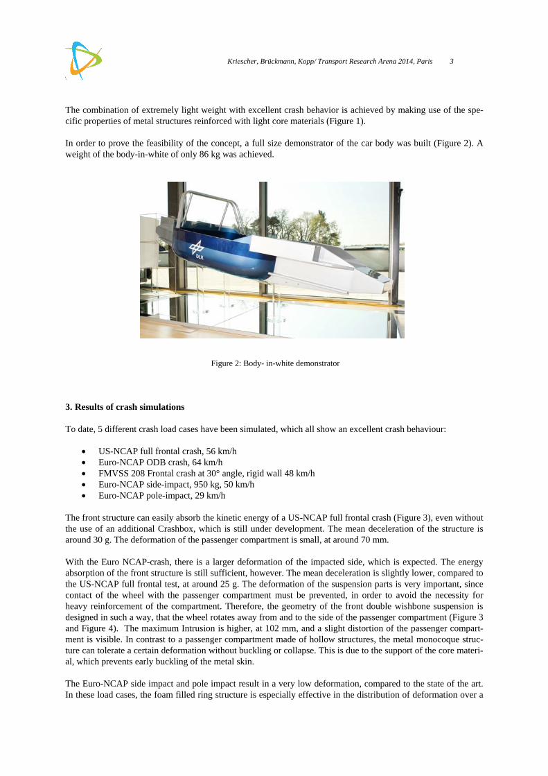
The combination of extremely light weight with excellent crash behavior is achieved by making use of the spe-cific properties of metal structures reinforced with light core materials (Figure 1). In order to prove the feasibility of the concept, a full size demonstrator of the car body was built (Figure 2). A weight of the body-in-white of only 86 kg was achieved.
Figure 2: Body- in-white demonstrator
3. Results of crash simulations
To date, 5 different crash load cases have been simulated, which all show an excellent crash behaviour:
US-NCAP full frontal crash, 56 km/h Euro-NCAP ODB crash, 64 km/h FMVSS 208 Frontal crash at 30° angle, rigid wall 48 km/h Euro-NCAP side-impact, 950 kg, 50 km/h Euro-NCAP pole-impact, 29 km/h
The front structure can easily absorb the kinetic energy of a US-NCAP full frontal crash (Figure 3), even without the use of an additional Crashbox, which is still under development. The mean deceleration of the structure is around 30 g. The deformation of the passenger compartment is small, at around 70 mm. With the Euro NCAP-crash, there is a larger deformation of the impacted side, which is expected. The energy absorption of the front structure is still sufficient, however. The mean deceleration is slightly lower, compared to the US-NCAP full frontal test, at around 25 g. The deformation of the suspension parts is very important, since contact of the wheel with the passenger compartment must be prevented, in order to avoid the necessity for heavy reinforcement of the compartment. Therefore, the geometry of the front double wishbone suspension is designed in such a way, that the wheel rotates away from and to the side of the passenger compartment (Figure 3 and Figure 4). The maximum Intrusion is higher, at 102 mm, and a slight distortion of the passenger compart-ment is visible. In contrast to a passenger compartment made of hollow structures, the metal monocoque struc-ture can tolerate a certain deformation without buckling or collapse. This is due to the support of the core materi-al, which prevents early buckling of the metal skin. The Euro-NCAP side impact and pole impact result in a very low deformation, compared to the state of the art. In these load cases, the foam filled ring structure is especially effective in the distribution of deformation over a

Kriescher, Brückmann, Kopp/ Transport Research Arena 2014, Paris 4
wide area. The maximum intrusion of the metal monocoque compared to a state of the art car body is lower in the side impact and pole crash and only slightly higher in the Euro-NCAP-ODB crash (Table 1).
Figure 3: Deformation of the car body and time-deceleration curve, US-NCAP
Figure 4: Deformation of the car body and time-deceleration curve, Euro-NCAP ODB
Figure 5: Deformation of the car body and time-deceleration curve, Euro-NCAP side impact

Kriescher, Brückmann, Kopp/ Transport Research Arena 2014, Paris 5
Figure 6: Deformation of the car body and time-deceleration curve, Euro-NCAP pole crash
Table 1: Maximum Intrusion of the metal-monocoque structure in comparison to a state of the art car body
Load case Max. Intrusion
Metal mono-coque structure
Max. Intrusion
State of the art body in white
Euro-NCAP frontal ODB 102 84
Euro-NCAP side impact 155 211
Euro-NCAP pole impact 206 381
4. Experimental results
The accurate crash simulation of sandwich components is difficult, because of the limitations in material model-ing. In order to verify the results of the crash simulation, a three-step approach is used:
- Investigation of the material properties by testing small samples - Verification of simulation results by testing critical components - Verification of simulation results by testing the entire car body structure
4.1. Tests on small samples
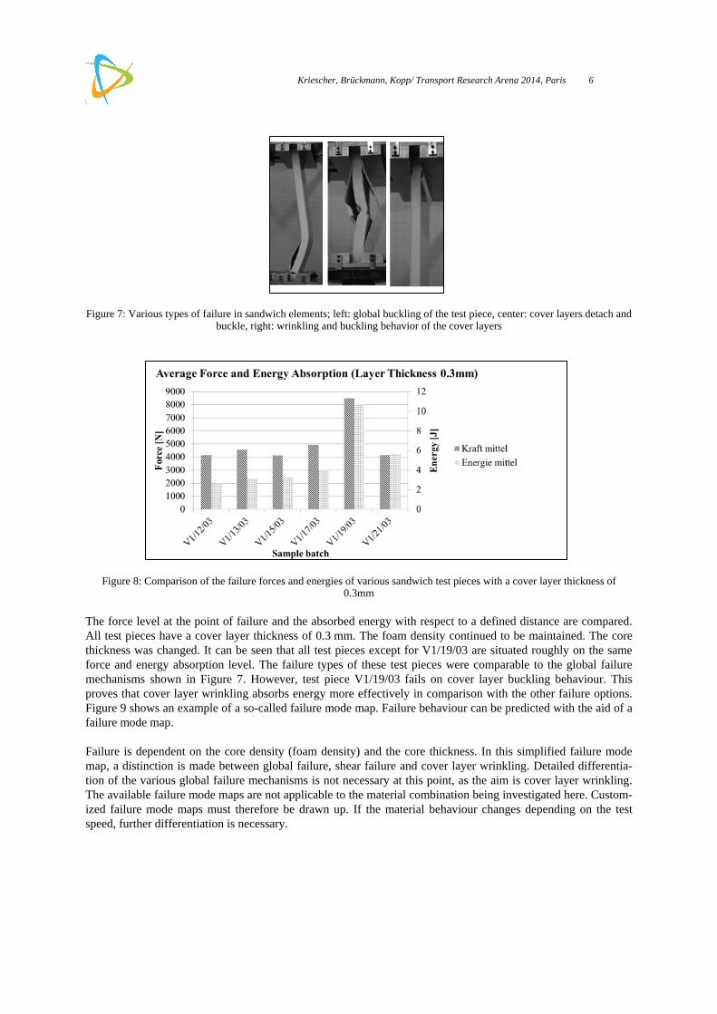
Generic sandwich elements: Using generic sandwich elements, the influence of cover layer thickness, foam density and core thickness on the failure behaviour of the test pieces was investigated. In Figure 7, three different failure modes are shown. On the left, global buckling can be seen. In the middle picture, buckling of the cover layers is visible, which leads to the detachment of large areas of the cover layers from the foam core. On the right, cover layer wrinkling has occurred. In this case, the test piece remains vertical and does not buckle. Small wrinkles form almost sym-metrical to the sandwich centre axis. In the area of the wrinkles, the cover layers become detached from the core. Local buckling behaviour and wrinkling is the preferred failure type for energy absorption in sandwich elements stressed in the in-plane direction. In Figure 8, a comparison is shown of various sandwich elements.
Kriescher, Brückmann, Kopp/ Transport Research Arena 2014, Paris 6
Figure 7: Various types of failure in sandwich elements; left: global buckling of the test piece, center: cover layers detach and buckle, right: wrinkling and buckling behavior of the cover layers
Figure 8: Comparison of the failure forces and energies of various sandwich test pieces with a cover layer thickness of 0.3mm
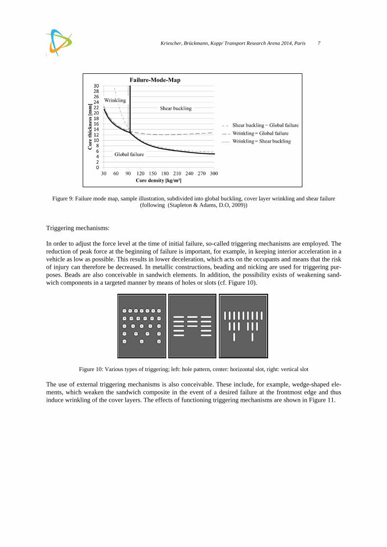
The force level at the point of failure and the absorbed energy with respect to a defined distance are compared. All test pieces have a cover layer thickness of 0.3 mm. The foam density continued to be maintained. The core thickness was changed. It can be seen that all test pieces except for V1/19/03 are situated roughly on the same force and energy absorption level. The failure types of these test pieces were comparable to the global failure mechanisms shown in Figure 7. However, test piece V1/19/03 fails on cover layer buckling behaviour. This proves that cover layer wrinkling absorbs energy more effectively in comparison with the other failure options. Figure 9 shows an example of a so-called failure mode map. Failure behaviour can be predicted with the aid of a failure mode map. Failure is dependent on the core density (foam density) and the core thickness. In this simplified failure mode map, a distinction is made between global failure, shear failure and cover layer wrinkling. Detailed differentia-tion of the various global failure mechanisms is not necessary at this point, as the aim is cover layer wrinkling. The available failure mode maps are not applicable to the material combination being investigated here. Custom-ized failure mode maps must therefore be drawn up. If the material behaviour changes depending on the test speed, further differentiation is necessary.
Kriescher, Brückmann, Kopp/ Transport Research Arena 2014, Paris 7
Figure 9: Failure mode map, sample illustration, subdivided into global buckling, cover layer wrinkling and shear failure (following (Stapleton & Adams, D.O, 2009))
Triggering mechanisms: In order to adjust the force level at the time of initial failure, so-called triggering mechanisms are employed. The reduction of peak force at the beginning of failure is important, for example, in keeping interior acceleration in a vehicle as low as possible. This results in lower deceleration, which acts on the occupants and means that the risk of injury can therefore be decreased. In metallic constructions, beading and nicking are used for triggering pur-poses. Beads are also conceivable in sandwich elements. In addition, the possibility exists of weakening sand-wich components in a targeted manner by means of holes or slots (cf. Figure 10).
Figure 10: Various types of triggering; left: hole pattern, center: horizontal slot, right: vertical slot
The use of external triggering mechanisms is also conceivable. These include, for example, wedge-shaped ele-ments, which weaken the sandwich composite in the event of a desired failure at the frontmost edge and thus induce wrinkling of the cover layers. The effects of functioning triggering mechanisms are shown in Figure 11.

Kriescher, Brückmann, Kopp/ Transport Research Arena 2014, Paris 8
Figure 11: Different triggering mechanisms; top: two-row slot triggering horizontally, below left: one-row hole triggering, below right: slot triggering vertically
Pictured on Figure 11 is a two-row triggering mechanism with horizontal slots. Below left, a variant with holes and, below right, a design with vertical slots can be seen. In the case of the two-row triggering mechanism with horizontal slots, symmetrical wrinkles form. The apex of the wrinkles is in the top row of slots, the bottom end in the second row of slots. This can be accounted for by the weakening of the cover layers and easier buckling made possible as a result. The wrinkles in a test piece triggered with holes form completely symmetrically, both toward the sandwich centre plane and toward the row of holes. In the case of a triggering mechanism with verti-cal slots, no symmetry toward the sandwich centre plane is discernible. Moreover, the partitions between the slots do not buckle reproducibly. The triggering mechanism with vertical slots is nevertheless functional, as the test piece does not fail elsewhere. Geometric influence on failure behaviour: The findings from the preliminary observations were incorporated in component tests. Figure 12 shows two dif-ferent test pieces. Pictured on the left is a box with a square cross section which was triggered with a row of holes, as hole triggering mechanisms proved to be the most appropriate. Repeated wrinkling can be seen. As predicted, in the actual course of the test the triggering mechanism worked, i.e. the initial failure occurred on the triggering mechanism and spread out from there in the form of wrinkles in line with the progress of the defor-mation. Pictured on the right is a cruciform structure, which was tested untriggered. During the test, a rotary mo-tion was apparent in the test piece, so that it became twisted. Nevertheless, wrinkles formed and no bending of the test piece was detected. The preliminary tests are being translated into the development of a complete vehicle body.
Figure 12: Compression tests on test pieces with geometric variance; left: triggered box structure, right cruciform structure

Kriescher, Brückmann, Kopp/ Transport Research Arena 2014, Paris 9
4.2. Component testing
Generic front structures of the lightweight vehicle were tested as part of the validation process, in preparation for full-scale testing of the car body. Figure 13 shows the front structure before and after crash testing. On the right side the force-displacement diagram of the deformation process is mentioned. Basically the front structure is built of sandwich panels which were bonded together. Thereby a box structure in the middle and two smaller box structures on the sides were assembled. The sandwich material is composed of thin aluminium layers (thickness 0,5 mm) and polyurethane foam (density 80 kg/m³) as core material. In front crash scenarios center part of the front structure absorbs the largest part of crash energy. In case of a serious accident the side boxes will absorb additional energy and will protect the passenger compartment.
Figure 13: vehicle front structure before and after crash testing
Figure 14: vehicle structure with highlighted front compartment (ct. fig. 13)
Before executing the dynamic tests, tests on the in-house hydraulic quasi-static test facility were made and the maximum load and the maximum deformation length were measured. In the crash test the vehicle front structure absorbed about 38 kJ of energy. That correlates to a crash speed of about 44 km/h. The front structure in the

Kriescher, Brückmann, Kopp/ Transport Research Arena 2014, Paris 10
crash test didn’t have a crash box ahead, which normally will absorb about 9 kJ of energy additionally. All in all, a good natured failure behaviour can be observed. Figure 14 shows the virtual body in white of the lightweight vehicle already shown in Figure 1. The front struc-ture shown in Figure 13 is colour-marked. Additionally the running gear and components of the powertrain, for example the batteries on top of the front compartment, the metal-hydride storage system behind the seats and the fuel cell on top of the rear part are represented.
5. Further proceeding and outlook
Building on the work described in chapter 4, the next major steps in the development process will consist of the testing of further components, leading up to a full-scale crash testing of the entire body in white. The results of these tests will then be compared to the simulation results. After a successful validation of the car body, a rolling demonstrator will be developed. In further development, the design of the demonstrator can easily be adapted to a 4-seater or even a cargo vari-ant, using the same design principles. For an efficient vehicle with an energy consumption of less than 80 Wh/km, an electric drive is intended. A body in white with extremely low weight serves as a starting point for a light weight vehicle. In order to keep the weight low, light, compact, highly powerful wheel hub motors will be used. Even more weight will be saved by using a drive by wire steering system. As is known from aircraft design, such a system reduces the amount of mechanical components and structural reinforcements, leading to low overall vehicle weight.
Kriescher, Brückmann, Kopp/ Transport Research Arena 2014, Paris 11
References
BMW. (2013). Von http://www.bmw.de/de/topics/faszination-bmw/bmw-i/konzept.html abgerufen Davies, H. C., Bryant, M., & et al. (2011). Design, development and manufacture of an aluminium honeycomb sandwich panel monocoque chassis for Formula Student competition. Journal of Automobile Engineering. Eckstein, L., & et al. (2011). Analyse sekundärer Gewichtseinsparpotenziale in Kraftfahrzeugen. ATZ 01/2011. Friedrich, H. E. (2013). Alternative Antriebe und Fahrzeugkonzepte Teil I, Werkstoffe und Bauweisen. Universität Stuttgart. Friedrich, H. E., & Hülsebusch, D. (2009). Elektro-Fahrzeugkonzepte und Leichtbau: Anforderungen für neue Werkstoffe? 1. Internationaler eCarTec Kongress für individuelle Elektromobilität, München. Kriescher, M., & et al. (2010). Metal-hybrid structures for an improved crash behaviour of car body structures. Materialien im Karosseriebau. Stapleton, S., & Adams, D.O. (2009). Core Design for Energy Absorption in Sandwich Composites. Journal of Composite Materials 43. Steinle, P., & et al. (2010). Innovative Vehicle Concept for the Integration of Alternative Power Trains. Stuttgarter Symposium.