Embed Size (px)
Citation preview

Technical report, IDE0752, June 2007
GERASOS—A Wireless Health Care System
Master’s Thesis in Computer System Engineering
T.V.Rajani Kanth
Supervisor: Urban Bilstrup
School of Information Science, Computer and ElectricalEngineering
Halmstad University


GERASOS – A Wireless health Care System
Master’s thesis in Computer System Engineering
School of Information Science, Computer and Electrical EngineeringHalmstad University
Box 823, S-301 18 Halmstad, Sweden
June 2007


i
Abstract
The present development of the demography of elderly people in the western world will generatea shortage of caregiver’s for elderly people in the near future. There are major risk that the lack ofqualified caregivers will result in deterioratio n in the quality of elderly care. One possiblesolution is the use of modern information and communication technology (ICT) to enable staff towork more efficiently. However, if ICT system is introduced into the elderly care it must done ina way which is acceptable from a humane perspective while at the same time increasing theefficiency of the personal that working in elderly care centers. This thesis investigates thetechnical feasibility of using a wireless mesh network for a social alarm system, in th e elderlycare. The System as such is not intended to replace the staff at an elderly care center but instead isintended to reduce staff workloads while providing more time for elderly care.
Keywords: wireless mesh, health care systems, wireless social alarms

ii

iii
Preface
This project is a master’s degree thesis and concludes the program Master of Science inComputer System Engineering at the School of Information Science, Computer and ElectricalEngineering at Halmstad University.
I would like to thank my supervisor, Urban Bilstrup. Without whose continuous guidance thiswork would not have been achieved.
T.V.Rajani KanthHalmstad University, June 2007

iv

v
Tables of Contents
ABSTACT................................ ................................ ................................ ................................ ..........
PREFACE ................................ ................................ ................................ ................................ ..........
CONTENTS ................................ ................................ ................................ ................................ .......
1. INTRODUCTION ................................ ................................ ................................ ......................... 11.1. Motivation ................................ ................................ ................................ ......................... 11.2. Project Goal ................................ ................................ ................................ ....................... 1
2. RELATED WORK................................ ................................ ................................ ....................... 32.1. Sensor Network for supporting elderly care home ................................ ............................ 32.2. Mobile clinical information System ................................ ................................ .................. 32.3. WLAN Architecture for Integrated time-critical and non-time-critical services withinmedical facilities................................ ................................ ................................ ....................... 42.4 Related Applications of Wireless Mesh Networking ................................ ......................... 62.5 WLAN Technology ................................ ................................ ................................ ............72.6 Wireless Mesh Networks ................................ ................................ ................................ ....82.7 Routing Protocols for wireless mesh network ................................ ................................ ....8
3. GERASOS – HEALTH CARE SYSTEM ................................ ................................ ..............113.1 The GERASOS system archi tecture................................ ................................ ................. 113.2 Network Architecture ................................ ................................ ................................ .......133.3 Software architecture ................................ ................................ ................................ ........14
4. RESULT ................................ ................................ ................................ ................................ ...194.1 Test 1 ................................ ................................ ................................ ................................ 194.2 Test 2 ................................ ................................ ................................ ................................ 214.3 Test 3 ................................ ................................ ................................ ................................ 234.4 Test-4................................ ................................ ................................ ................................ 25
5. RESULTS AND ANALYSIS ................................ ................................ ................................ .........29
6. CONCLUSION................................ ................................ ................................ .......................... 31
7. REFERENCE ................................ ................................ ................................ ............................ 33

vi

Gerosos-A Wireless Health Care System
1
1. Introduction
One emergent problem of the society today is the increase in the elderly population; this willgenerate a shortage of caregiver’s for elderly people in the near future. The lack of qualifiedcaregivers will result in deterioration in the q uality of the elderly care. This problem must besolved, in a way which is acceptable from a humanity perspective and at the same time increasingthe efficiency of the personal that works at elderly care centers. One possible solution is the useof modern information and communication technology (ICT) to enable staff to work moreefficiently. This thesis will investigate the feasibility of such an ICT system from a technologyperspective, within the context of making elderly care more efficient and still re taining acommitment to the human integrity. The system as such is not intended to replace the staff at anelderly care center but instead is intended to reduce staff workloads and provide more time for theelderly.
An example of one such an ICT system is the Gerasos system, which is a distributed computersystem, based on wireless communication. The system uses a wireless mesh network as acommunication infrastructure. This infrastructure is used as a backbone network for a largenumber of embedded computers, which provide a distributed system for supervision. A numberof sensors and alarm trigger devices are attached to the system e.g. .bed guard sensors, door guardsensors, alarm bracelets etc. These sensors and alarm triggers are battery powered and mus t havea very long life time. Therefore they can not be directly connected to the backbone networkinstead an extremely low power consuming wireless technology is used to communicate withthese devices.
1.1. Motivation
The rapidly growing elderly populat ion and the limited number of available caregivers result in areduction in the quality of the elderly care. The work load on the caregivers must somehow bedecreased to reach a feasible working and cost -effective situation. The main motivation of doingthis thesis is to investigate an ICT solution that provides cost effective way to monitor theactivities of the elderly care center continuously by using a distributed computer system with itscommunication based on wireless communication.
1.2. Project Goal
In this thesis parts of a modern Information and Communication technology (ICT) systemare implemented to assess the feasibility of the cost effective work based on wirelesscommunication to healthcare units. The main task is to implement a software de finedswitch, for packet switched traffic, which can handle the voice and logical connections ofthe gerasos health care system. Furthermore the performance should be investigated; thekey performance metrics are network capacity, reliability, and possible number ofsimultaneous voice connection.

Related Work
2

Gerosos-A Wireless Health Care System
3
2. Related Work
In this section a brief overview of related work are presented.
2.1. Sensor Network for supporting elderly care home
A example of an ICT system used in the elderly care is a system installed in an elderly care centerin Tokyo [1]. This system is based on a network of ultrasonic sensors. The goal of the system isto warn the caregivers about dangerous situations and avoid that accident occurrence in theelderly center. The main rationale behin d of this System is to remotely monitor the position ofelderly people detecting when a person is on his/her way to some hazardous area. If an alarm istriggered the personnel is directly informed about the position of the serious situation and can gothere to see whether the support is required or not. According to caregivers in nursing homes,major accidents are classified as two cases [1].
Falls: People fall from beds or fall wheelchairs. The major part of accidents occurs when theytransfer from the wheelchair to their bed or to a toilet seat etc.
Wandering around: some people tend to walk around day or night, as a result of medicalconditions akin to sleepwalking etc.
Today there are sensors available that can detect this type of behaviour in the n ursing home, butthey cannot prevent accidents. If we suppose that elderly people wear to wear some small deviceand the condition is monitored through that device, then the caregivers would be able to give amuch faster support. The problem is that they d o not always wear this device due to the fact theyare unable to remember the bring the device or taking off. The use of a CCT camera is anotherpossible solution but it unfortunately infringes the privacy.
The system consists of Badges ultrasonic receiv er badges, RF transmitters, and network devicesfor the receiver and host computer. The system activates every badge in periodically and receivesultrasonic pulses from the badge. The system then computes the distance from badge to eachreceiver from the time of flight date and by acting on this information determine the position thebadge.
2.2. Mobile clinical information System
Another type of application is a mobile clinical information system [2]. This comprises awireless bi-directional portable patient monitoring system, as shown in figure 1. It consists of acommunication interface which enables the care givers to receive patient data through a WLANand transmit parameters to the communication interface of the patient. This portable patientmonitor device contains a mobile computer connected to the communications interface to processthe patient data and care parameters; this system also contains bedside patient monitors toconnect centralized patient monitoring systems to improve efficiency. The advantage of acentralized monitoring system is that a small number of caregivers can monitor a large number ofpatients. These patient monitor systems are placed in patient rooms to measure heart rate, ECG,respiratory patterns etc.

Related Work
4
The Centralized patient monitor (CPM) is connected to servers, which retrieve and store patientdata, the CPM also receives telemetry signals through network. This server is directly connectedto hospital labs, pharmacy, voice router and numerous of portable patient monit oring devices(PPM) through wireless local area network (WLAN). The personnel can access real timeinformation from labs, pharmacy etc and send that data to PPMs, furthermore it will give updatedinformation to caregivers. This server can provide messages from CPM to PPMs; such messagesinclude current patient data, ECG waveforms and alarm signals. Personnel carry these PPMs andare always wirelessly connected by bi -directional to the patient data server. WLAN access pointsare connected to server to judge the signals between server and PPMs.
Figure 1. Clinical patient information monitoring system
2.3. WLAN Architecture for Integrated time -critical and non-time-critical services withinmedical facilities
Another example of a distributed patient monitoring system is given in [3]. The general intensionof this system is for supporting both real -time and non–real time wireless access to a hardwired

Gerosos-A Wireless Health Care System
5
network within the medical facility is given. This system consists of mu ltiple access points thatare distributed throughout a medical facility, as in figure 2, to provide wireless access to ahardwired network, these access points implements multiple WLAN protocol which includes areal time protocol for real-time patient monitoring and a standard WLAN protocol for generalpurpose wireless access. All these access points implement WLAN protocols so that all theWLAN and wireless devices share network access resources. All of these access points alsocontain RF location tracking modules; the main purpose of these modules is to track locations ofpatients, hospital personnel, capital equipment and disposable medical supplies. To avoidlockstep interference between access points operated in the same channel a TDMA timeslotrotation method is used.
Figure 2. System installed in hospital
In this hospital the system architecture consists of two separate Ethernet LANs, one for real timepatient monitoring another for non - real-time applications. This system consists of two types ofaccess points multi-band access point (WMTS/802.11) and single -band (WMTS) access pointsare required for patient monitoring. These access points are placed in patient areas of the hospital,i.e. step-down units, surgical wards etc. here each access point sets up data connections with a

Related Work
6
fixed number of patients at a time and multiple access points are placed side by side within morepatients roaming areas. Furthermore these multi -access points are placed throughout the h ospitalproviding accesses to the hospital network. The main function of access points are real -timepatient monitoring, wireless access to different network resources i.e. hospital informationsystems (HIS) and clinical information system (CIS) databases, captured ECG data, pagingsystem etc. these access points also contains location -tracking modules the main purpose ofwhich is to track the locations e.g. patients, hospital personnel, capital equipment, disposablesupplies etc. furthermore this system a lso contains T1 interface to view the remote viewing ofreal-time telemetry data
2.4 Related Applications of Wireless Mesh Networking
Some of applications of mesh networking are deployed in the market, e.g. intelligenttransportation systems, public int ernet access, public safety and the underground mining industry.
2.4.1 Intelligent transportation systems
Wireless mesh networks can be used in intelligent transportation systems due to low cost,flexibility and more secure inter communication. The real –time travel information system(PORTEL) [4] is a system which is provides a city wide public transportation communicationnetwork. The main intension of this system is to provide real –time information to passengers.This system support 500 buses and is ope rated by a wireless mesh technology. The systemprovides real-time information, when the bus is available in addition to the ultimate destinationand arrival schedules.
2.4.2 Public Internet access
Today Internet service provides (ISP’s) can depend on Wi -Fi technology to provide theirbroadband wireless internet access. It is difficulty to deploy this broadband wireless connectivity[4] in urban, sub-urban and rural environments due to the extremely high cost of networkinfrastructure. To avoid this probl em, a wireless mesh is more suitable. The cost of networkinstallation is very small for a wireless mesh compared to use standard wired access points forwireless internet access.
2.4.3 Public Safety
Today some urban emergency networks are built the principle of the wireless mesh, i.e. used bypolice department, fire department, emergence department etc. All these departments are dependon good communication facilities, a wireless mesh network can provide this in urbanenvironments due to the fact that they provide good mobile support, flexibility and highbandwidth. For the moment, at least one police department in U.S . use a wireless mesh network[4]. All patrolling cars are equipped with laptops and motorcycle, and bicycle with PDA’s . Thecommunications between these units are conducted over a wireless mesh network.2.4.4 Underground Mines Industry:
Gerosos-A Wireless Health Care System
7
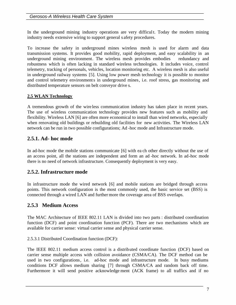
In the underground mining industry operations are very difficul t. Today the modern miningindustry needs extensive wiring to support general s afety procedures.
To increase the safety in underground mines wireless mesh is used for alarm and datatransmission systems. It provides good mobility, rapid deployment, and easy scalability in anunderground mining environment. The wireless mesh provides embodies redundancy androbustness which is often lacking in standard wireless technologies. It includes voice, controltelemetry, tracking of personals, vehicles, location monitoring etc. A wireless mesh is also usefulin underground railway systems [5]. Using low power mesh technology it is possible to monitorand control telemetry environment s in underground mines, i.e. roof stress, gas monitoring anddistributed temperature sensors on belt conveyor drive s.
2.5 WLAN Technology
A tremendous growth of the wire less communication industry has taken place in recent years.The use of wireless communication technology provides new features such as mobility andflexibility. Wireless LAN [6] are often more economical to install than wired networks, especiallywhen renovating old buildings or rebuilding old facilities for new activities. The Wireless LANnetwork can be run in two possible configurations; Ad -hoc mode and Infrastructure mode.
2.5.1. Ad- hoc mode
In ad-hoc mode the mobile stations communicate [6] with ea ch other directly without the use ofan access point, all the stations are independent and form an ad -hoc network. In ad-hoc modethere is no need of network infrastructure. Consequently deployment is very easy.
2.5.2. Infrastructure mode
In infrastructure mode the wired network [6] and mobile stations are bridged through accesspoints. This network configuration is the most commonly used, the basic service set (BSS) isconnected through a wired LAN and further more the coverage area of BSS overlaps.
2.5.3 Medium Access
The MAC Architecture of IEEE 802.11 LAN is divided into two parts : distributed coordinationfunction (DCF) and point coordination function (PCF). There are two mechanisms which areavailable for carrier sense: virtual carrier sense and physical carrier sense.
2.5.3.1 Distributed Coordination function (DCF):
The IEEE 802.11 medium access control is a distributed coordinate function (DCF) based oncarrier sense multiple access with collision avoidance (CSMA/CA). The DCF method can beused in two configurations , i.e. ad-hoc mode and infrastructure mode. In busy mediumsconditions DCF allows medium sharing [7] through CSMA/CA and random back off time.Furthermore it will send positive acknowledge ment (ACK frame) to all traffics and if no

Related Work
8
acknowledgement has been received retransmission is scheduled by the sender . The mainfunction of CSMA/CA protocol is that if multiple STAs are able to access each other in a mediumit will reduce collision because theses multiple STAs are available again waiting for the mediumto avoid random back off procedure [7] to resolve contention conflicts in the medium.
2.5.3.2. Point Coordination Function (PCF):
Another centralized method available in the IEEE 802.11 standard [7] is known as the pointcoordinate function (PCF). This method is only used in infrastructure network mode. This accessmethod uses a point coordinator (PC); this is implemented in BSS access points, to know whichSTA presently right to transmit.
PCF uses a virtual carrier sense mechanism. In this method STAs set network allocation vector(NAV) to gain control of medium [7] through distributing information w ithin beaconmanagement frames. Furthermore frames transmitted through PCF uses inter -frame space, socalled IFS, which is too small when compared to IFS frames transmitted via DCF. Because ofsmaller (IFS), the point coordinated traffic has maximum prefer ence to access the medium. ThisPCF access method is used to form a contention free (CF) access method. The main function ofthis access method is that it can to some extent support real -time traffic.
2.6 Wireless Mesh Networks
In a wireless Mesh network architecture nodes or wireless routers are communicating directlywith each other [4], so data can travel from user to user without any access points. The networkwith wireless routers forms a wireless backbone. Furthermore it gives multi-hop connectivitybetween users and gateways. Wireless routers and access points create a wireless backhaulcommunication due to forwarding which provides [4] mobile users with low cost and highbandwidth. The main function of backhaul is it fo rwards traffic from original node to access pointfrom which it can be distributed over an external network. While in mesh case the traffic is inuser’s devices when it traverses the wireless backbone and is distributed over the internet work.
Using wireless mesh network as communication infrastructure is cheap, it does not demand forany wiring on the building; provide good scalability in coverage area and capacity. A wirelessmesh network does not need any backhaul instead radio is used to relay message s between thestations so the deployment is very easy. Wireless mesh networks have so far mostly been used inso called citizen networks providing wireless internet access. The capacity of the physical layer ofthe IEEE WLAN standard has been increasing ra pidly last years and the bandwidth of WLANnow reaches 54-mbps and will soon provide a bandwidth far in excess of above 100 mbps.
2.7 Routing Protocols for wireless mesh network
In wireless mesh networks there is no fixed node, nodes suddenly add or delete in a meshnetworks. To communicate between these nodes [8] they require specialized protocols whichmainly focus on node changing concept s, i.e. new nodes tell to their neighbour node when theyare present and relay the information from the neighbour node. The function of routing protocolin mesh network is too choosing an easier route between the nodes to get high throughput, fast

Gerosos-A Wireless Health Care System
9
operation. The routing table which is maintained between the nodes maintain smallerconnections and up date the table with the new nodes when adding or deleting.

Related Work
10

Gerosos-A Wireless Health Care System
11
3. GERASOS – HEALTH CARE SYSTEM
This section provides a brief overview of the network architecture and software architecture ofthe Gerasos health care system The System consists of sensors, sensor hubs, beepers, PDAs andconnectors, The main function o f sensors is to measure [9] physical force. Every sensor isconnected to an sensor hub, sensors send alarm message to the sensor hub. This sensor hubmaintains sensor status which is connected to display; this also called the human machineinterface (HMI) of the system. In this system handling devices are called beepers; these mainfunctions are to tell which sensor hub has triggered the alarm, an alarm message is showing in thedisplay which is connected to the beepers. When sensor hubs receive an alarm me ssage from anyone of the connected sensors, it will send a message to beepers. When an alarm message isreceived by beeper, the person who is holding that beeper can go to their location of sensor huband reset the alarm and beeper holding person can also see the display of the sensor hub thesensors of which trigger the alarm.
3.1 The Gerasos system architecture
The Gerasos system architecture is divided into logic layer, Sensor or Interaction layer, and thenetwork layer. In the sensor layer numerous heterogeneous sets of hardware devices areconnected such as bed guard sensors, door guard sensors, bracelets alarm button, fire guard etc. Inthe network layer room/corridors module, WLAN module, WLAN Mesh Router, are present. Inthe logic layer the soft-switch is placed to control the traffic in the network.

Gerosos- Health Care System
12
Figure 3. Overview of Gerasos system architecture
3.1.1 Bed guard sensor
The function of bed guard senor is to be placed in bed. It will detect when any person sitting inthe bed has been injured and sends message to hand unit. This sensor is an equipped with acapacitive wireless pressure sensor to measure the physical force on it. This sensor operates inthree modes i.e. non -associated mode, sensing mode and sensing alarm mode. In non-associatedmode, the sensors send messages in every minute, sensing mode it will send messages in everytwenty seconds, sensing alarm mode it will send messages on physical force change events.
WLAN MESH
= WLAN module
RKM
H H
RKM RKM
WLANNODE
= Bed guard sensor
= Door guard sensor
= Bracelet
= Wireless exit control
Internet
= WLAN mesh
= Wireless low powerprotocol
= WLAN Mesh router
H = Hand unit
RKM = Rooms/corridors module
= Ethernet.
= Short range wirelesscommunication link
= Wireless fire detector
Sensor/interaction layer
Networks layerRKM RKM
WLANNODE
WLANNODE

Gerosos-A Wireless Health Care System
13
3.1.2 Door guard sensors
These sensors are placed in door s. It will detect if the door is opened and send message to handUnit.
3.1.3 Hand Unit
The function of a hand unit is carried by the personnel and is a form of beeper that informs thecare takers which alarm have been triggered . It furthermore supports voice communication to thebracelet alarm buttons.
3.1.4 Bracelets alarm button
The function of the bracelets is an alarm button which when triggered opens a voice channel toavailable personnel carrying a hand unit.
3.1.5 Fire guard
The function of fire guard is that it detect if fire occur in a patient’s rooms, corridors etc.
3.1.6 WLAN Mesh Router
The Function of WLAN mesh is that it forms a wireless mesh between all clients and the softswitch. In the router that forms the wireless mesh an open source firmware from freifunk networkis running.
3.1.7 Soft-Switch
The function of soft-Switch is it maintains all data given by different hosts. Message switchingwill take places in soft switch mode i.e. all incoming messages and out going messages switchingwill be going through the soft-switch.
3.2 Network Architecture
The Gerasos system is to a large extent based on standard hardware and software components.Previously the Gerasos system had a Bluetooth based backbone network; an ongoing work is toconvert the backbone to a wireless mesh network instead. The new concept is based on LinksysWRT54GL WLAN routers running open source firmware from freifu nk network [10]. Therouters form a wireless mesh network where the RKM is working as end nodes, figure 3. Theintelligence of the system is centralized in the form of a system computer; a standard PC thecommunication is based on that serial links which are tunnelled on top of TCP/IP connecti onswhich are connected to the system computer , i.e. the soft switch. The system computer works asswitch solely implemented in the software. The virtual serial links are represented as TCP/IP

Gerosos- Health Care System
14
address and port numbers in the application running on the syst em computer where theapplication provides the switching functionality of ingoing and outgoing messages. Since thenetwork layer is built upon Ethernet and TCP/IP and standard WLAN it opens up for the use ofCOTS units, e.g. standard WLAN equipped PALM and cell phones can be used in the system.Furthermore the system scalability becomes much better than the previous network layer basedon Bluetooth and it enables the possible use of v oice connections over network, e .g. VOIP.
3.3 Software architecture
Most logics and functions in the Gerasos system are centralized on the system computer. Alldatabases registers are put there, with some exception for some information that is also mirroredin the RKM’s. The main task for the system computer is to work as software defied switch, theAPI for the software defined switch for sockets. It also supports the logical topology (i.e.connection set up between RKM and beepers) and handover for migrating units, with the help ofa number of registers. The system computer als o contains a web based interfaces forconfiguration and management of the system. A number of registers and databases are used forerror logging and so fourth. The system computer maintains the databases of all the information.The software architecture is shown in figure 4. The API for the application layer and systemcomputer is in the form of sockets through which the sockets messages are forwarded and settingup logic connection.

Gerosos-A Wireless Health Care System
15
s Figure 4. Software architecture of Gerasos system WLAN --- WLAN modules Bed guard, Door guard, Hand guard, Bracele tsHMI-------Human machine interface Alarm filteringAPP---- Application level protocol
WLAN MESH
Alarm filtering
Sample
HMI
Sensor/interactions layer
Networks topology
Bed guard
System computer
APP & LINK
APP & LÄNK
APP
APP
P
RKM
WLAN/serial port module
Sample
APP &LINK
Message filtering,network topology,logging, errordetection, handoveroch systemconfiguration
TCP/UDP IP
HMI
Hand unit
APP
APP &LINK
Logic layer
APP
Bracelet
HMI
APP & LINK
Door guard
Internet connection

Gerosos- Health Care System
16
3.3.1 Soft Switch
In the soft-switch server sockets are created, from the server connections to clients are set up.Each client system will be identified to the server by its individual IP address. The clients sendmessages to the soft switch; the soft switch forwards those messages to other clients. The softswitch maintains all incoming messages and out going messages in its buffer. In the buffer it willmaintains all incoming messages and out going messages in individual queues for eachconnection. If the buffer is overflows it will reject messages.
3.3.2 Flowchart for Software Architecture of the soft switch
The soft switch starts to process the data, at the other end the host also starts to send data to thesoft switch. The soft switch subsequently receives that data and processes which it then send toanother host, the flowchart is shown in figure.5.

Gerosos-A Wireless Health Care System
17
Figure.5 Flow chart soft switch
Host Starts
Host reads usercommand
Soft Switch starts
Soft Switch receivesdata
Soft Switchprocesses data
Soft Switch returnsresults
Host sends Data
Host reads results
Host display results

Gerosos- Health Care System
18

Gerosos-A Wireless Health Care System
19
4. Results:
Performances tests are carried out on the soft switch, which is connected with WLAN routers ona wired network. In this test the soft switch running fedora Linux kernel version 2.6., TheWRT54GL WLAN Routers is running an open source firmware from freifunk, and the hostsystems are also running a Linux distribution fedora, kernel version 2.6. These tests measure thethroughput and average delay for different connections.
Figure 6. One - hop- Network
4.1 Test 1
A one hop network consists of two WLAN routers, and two client systems are set up. The softswitch is connected with one of the WLAN routers, second router is connected to the h ost system.The soft switch and host systems form a WLAN mesh figure 6. In this one hop network, networkthroughput test is measured.
To measure the network throughput 10000 packets to the soft switch from h ost systems figure 7.Each packet contains of 128 bytes of data and within time intervals of 10 ms sending data to softswitch from host systems, figure 8. The packet loss is subsequently lost in the host systems with

Results
20
different connections. Soft switch and host systems communicate through TCP/IP connections.
Figure.7 Soft switch receiving data from Clients
Figure.8 Clients sending data to soft switch in the given time interval
Results
In this test the packet loss rate is calculated be tween two host systems. Here one connectionmeans two host systems are connected to the soft switch with two WLAN routers. Figure 9 showsthe results of packet loss verses the number of connections. To test the performance, 8connections were taken.
From the results it would appear that the packet loss rate increases with increasing number ofconnections, up to certain point and later on it kept at same value, which is due to traffic intensitybeing high in the network. Because with increasing the number of connections, soft switchbecomes overloaded this due to many client systems simultaneously sending messages to softswitch, due to high congestion in packet switched traffic and messages in soft switch aredropping .so packet loss rate increases with increasing number of connections.

Gerosos-A Wireless Health Care System
21
Packet loss =
packetsSendingofNumber
packetsReceivedofNumber
1 1.5 2 2.5 3 3.5 40
1
2
3
4
5
6
7
8
No. of Connections
Pac
ket L
oss
(Per
cent
age)
Figure 9. Packet loss versus number of connections.
4.2 Test 2
In this test measurement, the delay was measured in sending 10000 packets to soft switch fromhost systems. Each packet contains 128 bytes of data and in the intervals of 10 ms sending data tosoft switch from host systems, figure 8. Here calculate the average delay in host systems withdifferent connections is calculated.
Results
In this test the average time between two host systems was calculated. Here one connectionmeans that two client systems are connected to the soft switch via two WLAN routers, figure 10shows the results of the average time delay versus the number of connections. The performance

Results
22
was tested by taking eight connections. From the results it would appear that the delay increaseswith an increasing number of connections, up to certain point to keep within the same value, dueto traffic intensity being high in the network. Because with increasing the number of connections,soft switch becomes overloaded this due to many client systems simultaneously sendingmessages to soft switch, due to high congestion in packet switched traffic average delayincreases, this is due to high flooding in the network .
Figure 11 shows ping testing results of one hop network, the average time delay versus number ofconnections. From the resul ts it would appear that the delay gradually increases with anincreasing number of connections. After observing result we can say that very less delay withmore number of connections. This is due to low network traffic congestion in the network.
1 1.5 2 2.5 3 3.5 41
2
3
4
5
6
7
8
9x 10⁸
No. of Connections
Del
ay (m
icro
sec
.)
Figure10. Delay versus number of connections.

Gerosos-A Wireless Health Care System
23
1 1.5 2 2.5 3 3.5 42
2.5
3
3.5
4
4.5
No. of Connections
Del
ay (m
illi s
ec.)
Figure 11. Delay versus number of connections.
4.3 Test 3
A two hop network consists of a soft switch, Three WLAN Routers and h ost systems. Softswitch is connected with one WLAN router and the second router is connected to host systems, Inbetween first and second routers, the third router is placed. The soft switch, host sys tems androuters form a WLAN mesh figure 12. In this two hop network the network throughput test ismeasured.

Results
24
Figure.12 Two- hop- Network
This test measures the network throughput, by sending 10000 packets to soft switch from h ostsystems, figure 7. Each packet contains 128 bytes of data and within a time interval of 10 ms,sending data to soft switch from host systems, figure 8. Then calculate the packet loss rate in h ostsystems with different connections. Soft switch and host systems communicate through TCP/IPconnections.
Results
In this test the packet loss rate between two h ost systems is calculated. Here one connectionmeans that two host systems are connected to the soft switch with two WLAN routers, the graphin figure 13 shows the results of packet loss versus number of connections. Performance wastested by taking 8 connections. From the results it would appear that the packet loss rate increaseswith increasing number of connections, up to certain point and later on it kept at same value,which is due to traffic intensity being high in the network. Because with increasing the number o fconnections, soft switch becomes overloaded this due to many client systems simultaneouslysending messages to soft switch, due to high congestion in packet switched traffic and messagesin soft switch are dropping, this is mainly due to number of router s increases messages aredropping in the network, i.e. the packet loss rate increases with increasing number of connections.

Gerosos-A Wireless Health Care System
25
1 1.5 2 2.5 3 3.5 40
5
10
15
20
25
30
35
40
45
No. of Connections
Pac
ket L
oss
(Per
cent
age)
Figure 13. Packet loss versus number of co nnections
4.4 Test-4
This test measures the delay. To measure the delay, 10000 packets have been sent to the softswitch from each host systems. Each packet contains 128 bytes of data , using a time interval 10ms sending data to soft switch from host sys tems, figure 8. Here the average delay is calculated inhost systems with different connections.
Results
In this test the average time between two host systems is calculated. Here one connection meansthat two host systems are connected to soft switch with two WLAN routers. Figure 14 shows theresults of an average time delay verse number of connect ions. Performance was tested by setting8 connections. From the results it would appear that the delay increases with an increasingnumber of connections, up to certain point to keep within the same value, due to traffic intensitybeing high in the network. Because with increasing the number of connections, soft switchbecomes overloaded this due to many client systems simultaneously sending messages to softswitch, due to high congestion in packet switched traffic average delay increases, this is due tohigh flooding in the network. The graph in figure 15 shows ping testing results of two hop

Results
26
network, the average time delay versus number of connections. From the results it would appearthat the delay gradually increases with an increasing number of connections. After observingresult we can say that very less delay with more number of connections. This delay is mainly dueto increases of number of routers and slightly network traffic congestion in the network.
1 1.5 2 2.5 3 3.5 41
2
3
4
5
6
7
8
9
10x 108
No. of Connections
Del
ay (m
icro
sec
.)
Figure 14. Delay versus number of connections.

Gerosos-A Wireless Health Care System
27
1 1.5 2 2.5 3 3.5 40
50
100
150
200
250
300
350
400
450
No. of Connections
Del
ay (m
illi s
ec.)
Figure 15. Delay versus number of connections.

Results
28

Gerosos-A Wireless Health Care System
29
5. Results and Analysis:
The goal of the measurement is to investigate the performance of the soft switch implementationfor which the key measurements are throughput and average delay. To judge the performancedifferent test was conducted with one-hop network and two-hop networks. The goal of these testshas been to determine the performance of gerasos health care systems.
For the one-hop network the packet loss rate is less for less number of connections. Packet lossrate increases with an increasing number of connections up to certain point and later onmaintaining the same values. This is due to high traffic intensity in the network. Furthermore foraverage delay is considerable, the delay increases with the increasing number of connections upto certain point after that it will maintain the same value.
For two-hop network the packet loss rate is high for different connections. Packet loss rateincreases with an increasing number of connections up to certain point and later on maintainingthe same values. This is due to traffic intensity high in the network; consequently trafficcongestion is high in the network. Furthermore for average delay is considers, the delay is highfor different connections. Delay increases with increasing number of connections up to certainpoint after that it will maintaining the same value. This due to traffic congestion is high in thenetwork.
Voice connections are concerned with delay and throughput is less in one –hop network,consequently it is possible to send voice m essages in this network. Where as in two hop networksdelay and throughput is considerable, it is consequently not possible to send voice messages inthis network, ultimately drop will occur in voice messages. This due to congestion in network.
After observing results from one-hop network and two hop networks, Soft switch can’t suppor tmore connections, which is due to high traffic congestions in the network. Network capacity isincreasing then packet loss rate is also increases. This is due to increasing numbers ofconnections. Furthermore delay is also increases with an increasing number of connections.

Result and Anaylsis
30

Gerosos-A Wireless Health Care System
31
6. Conclusion
This thesis investigated the performance of the soft switch implementation le ading to thefollowing conclusions.
The performance evaluation of soft switch in terms of throughput and average delay are assessedwith one-hop network and two-hop networks by considering different test conditions.
Our measurement indicates that throughput and average delay bound the utilization of softswitch. A bottleneck is forming in the soft switch due to traffic congestion by increasing thenumber of connections, which leads to an increase in average delay.
The present soft switch implementation on the current hardware platform can not support voicemessages due to high throughput and delay.
Future work based on this project is to investigate the performance complicated networkarchitectures with multiple routers, different connections and tedious traffic patte rn systems

32

33
7. References:
[1] Hore T, Nishida .Y, Aizawa H, Murakami.S, and Mizoguchi.H. “ Sensor Network forsupporting elderly care home” Proceedings of the IEEE Sensors 2004, Volume 2, 24-27 October2004 pp. 575-578.[2] G. M.Hutchinson and J. W. Brimfield, and Mequon, Mobile clinical information System , Pub.No: US 2005/0192845 A1 WI (US), Brookfield, WI, U.S, September 1, 2005.[3] Stephen E.Hannah, Edward L.Flanders, and Scott J.Carter, Wireless LAN Architecture forIntegrated time-critical and Non-time-Critical Services within Medical Facilities , Pat No: US2004/0170154 A1 CA (US) ,Placentia, CA,U.S, September 2004[4] Bruno R, Conti M, and Gregori E, “ Mesh Networks: Commodity Multi -hop ad hoc Networks”IEEE Communication Magazine , Volume 43, Issue 3, March 2005, pp. 123-131.[5] Kennedy, G.A, Foster, P.J., “ High Resilience Networks and Microwave Propagation inUnderground Mines ,” Wireless Technology, European Conference, September 2006, pp.193 -196.[6] Yeh J-H Chen JVH-C ,and Lee C-C “ WLAN Standards “,Proceedings of IEEE Potentials,Volume 22, Issue 4, 2003, pp.16-22.[7] Wireless LAN Medium Access Control (MAC) and Physical Layer (PHY) Specifications.Institute of Electrical and Electronics Engineers, 2003.[8] List of Ad-hoc Routing protocols – Wikipedia, the free encyclopedia, May 3, 2007 URL:http://en.wikipedia.org/wiki/List_of_ad -hoc_routing_protocols[9] Bilstrup, U and Wiberg, P. -A. “An Implementation of a 3-tier hierarchical wireless SensorNetwork “,in proceedings of the IEEE Industrial Informatics confrence, August 2006, Pages 138-143.[10] Information available at Http:// freifunk.net (070615)