Embed Size (px)
Citation preview

PRESTO
PRESTO GEOSYSTEMS® 670 N PERKINS STREET, APPLETON, WISCONSIN, USA 54914 Ph: 920-738-1707 or 800-548-3424 ■ Fax: 920-738-1222
e-mail: [email protected] WWW.PRESTOGEO.COM/ GWSL000 16-DEC-2013
GEOWEB®
SLOPE PROTECTION SYSTEM
INSTALLATION GUIDELINE

PRESTO
GEOWEB®
SLOPE PROTECTION SYSTEMINSTALLATION GUIDELINE
GW/SL000 16-DEC-2013 COPYRIGHT 2013 – PRESTO GEOSYSTEMS
Table of Contents
Site Preparation ............................................................................................................................................. 1
Figure 1 Slope Preparation ................................................................................................................... 1
Geotextile Separation Layer .......................................................................................................................... 1
Figure 2 Geotextile Placement .............................................................................................................. 1
Installation of Geoweb® Sections ................................................................................................................. 1
Figure 3 ATRA® Anchor Placement ...................................................................................................... 1
Figure 4 Placement of Geoweb® Section .............................................................................................. 2
Figure 5 ATRA® Anchor Installation Methods ....................................................................................... 2
Figure 6 ATRA® Key Connection Device .............................................................................................. 2
Installation of Geoweb® Sections on Curved or Irregular Surfaces ............................................................. 3
Figure 7 Tapered Expansion of Section ................................................................................................. 3
Figure 8 Curved Expansion of Section .................................................................................................. 3
Figure 9 Field Cutting of Geoweb Section to Form Taper ..................................................................... 3
Limiting Vertical Curvature of Geoweb® Sections ........................................................................................ 4
Table 1: Cell Depth vs. Limiting Radius of Curvature ........................................................................... 4
Preparation of Tendon Geoweb® Sections................................................................................................... 4
Figure 10 Tendon Insertion .................................................................................................................... 4
Terminating and Anchoring Tendons ............................................................................................................ 4
Figure 11 Termination of Integral Tendons ........................................................................................... 4
Figure 12 End Anchorage of Tendons .................................................................................................. 4
Internal Anchoring ......................................................................................................................................... 5
Figure 13 Internal Anchors .................................................................................................................... 5
Non-Slip Tendon Internal Anchorage ............................................................................................................ 5
Figure 14 Moore Hitch Non-Slip Connection ........................................................................................ 5
Crest Anchorage of Tendon Geoweb® Systems .......................................................................................... 5
Figure 15 Deadman Crest Anchor ........................................................................................................ 5
Figure 16 ATRA® Tendon Clips ........................................................................................................... 6
Figure 17 Threading Tendon and Attaching ATRA Tendon Clips ......................................................... 6
Placement of Infill .......................................................................................................................................... 7
Figure 18 Excavator .............................................................................................................................. 7
Figure 19 Loader ................................................................................................................................... 7
Figure 20 Mobile Conveyor ................................................................................................................... 7
Figure 21 Skip ....................................................................................................................................... 7
Figure 22 Chute .................................................................................................................................... 7
PRESTO
GEOWEB®
SLOPE PROTECTION SYSTEMINSTALLATION GUIDELINE
COPYRIGHT 2013 – PRESTO GEOSYSTEMS GW/SL000 16-DEC-2013
Dimensions and Weights of Palletized Geoweb® Sections ......................................................................... 8
Table 2: V-Series Geoweb® Shipping Dimensions and Weights.......................................................... 8
Infill Volumes ................................................................................................................................................. 8
Table 3: Infill Volumes for Geoweb® Sections ...................................................................................... 8
Tools and Equipment .................................................................................................................................... 8
Table 4: Standard Construction Tools for Installation of the Geoweb® System ................................... 8
Excavation and Materials Handling Equipment ........................................................................................ 9
Compaction Equipment ............................................................................................................................. 9
Limited Warranty ........................................................................................................................................... 9
ATTACHMENT 1 -TENDON MARKING METHOD .................................................................................... 10
ATTACHMENT 2 -ATRA TENDON CLIP INSTALLATION METHOD ........................................................ 11

PRESTO
GEOWEB®
SLOPE PROTECTION SYSTEMINSTALLATION GUIDELINE
GW/SL000 16-DEC-2013 COPYRIGHT 2013 – PRESTO GEOSYSTEMS PAGE 1 OF 11
NOTE: The following installation techniques and recommendations may require an evaluation by Presto Geosystems to determine applicability of use for individual project requirements.
Site Preparation
Remove existing vegetation from the proposed slopes.
Excavate and shape the slope section.
Place, compact and shape required earth fill.
Dig toe-in trenches at the crest and perimeter of the slope as required.
Figure 1 Slope Preparation
Geotextile Separation Layer
Most non-vegetated slope applications involve a non-woven or woven geotextile separator layer at the sub grade surface. When required, this separation layer is critical to the performance of the slope system. Refer to Figure 2.
Install geotextile separation layer in accordance with manufacturer’s instructions and ensure that minimum overlaps are maintained.
Ensure geotextile is placed in perimeter toe-in trenches.
Anchor the edges of the geotextile separation layer in accordance with manufacturer instructions to prevent movement.
Figure 2 Geotextile Placement
Installation of Geoweb® Sections
Drive a row of ATRA Stake Anchors along the upper edge of the proposed slope protection area. Space the stakes at pre-determined single cell centers. See Geoweb® Anchor Spacing Charts for guidance.
Partially expand the Geoweb® section and place the end cell of the section over its corresponding edge stake. Ensure the ATRA® Stake Clip arm is hooked over the cell wall. Refer to Figure 3.
Figure 3 ATRA® Anchor Placement
PRESTO
GEOWEB®
SLOPE PROTECTION SYSTEMINSTALLATION GUIDELINE
PAGE 2 OF 11 COPYRIGHT 2013– PRESTO GEOSYSTEMS GW/SL000 16-DEC-2013
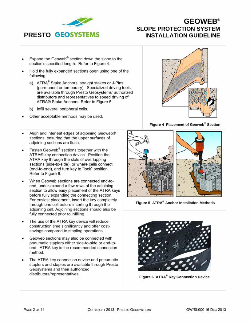
Expand the Geoweb® section down the slope to the section’s specified length. Refer to Figure 4.
Hold the fully expanded sections open using one of the following:
a) ATRA® Stake Anchors, straight stakes or J-Pins (permanent or temporary). Specialized driving tools are available through Presto Geosystems’ authorized distributors and representatives to speed driving of ATRA® Stake Anchors. Refer to Figure 5.
b) Infill several peripheral cells.
Other acceptable methods may be used.
Figure 4 Placement of Geoweb® Section
Align and interleaf edges of adjoining Geoweb® sections, ensuring that the upper surfaces of adjoining sections are flush.
Fasten Geoweb® sections together with the ATRA® key connection device. Position the ATRA key through the slots of overlapping sections (side-to-side), or where cells connect (end-to-end), and turn key to “lock” position. Refer to Figure 6.
When Geoweb sections are connected end-to-end, under-expand a few rows of the adjoining section to allow easy placement of the ATRA keys before fully expanding the connecting section. For easiest placement, insert the key completely through one cell before inserting through the adjoining cell. Adjoining sections should also be fully connected prior to infilling.
The use of the ATRA key device will reduce construction time significantly and offer cost-savings compared to stapling operations.
Geoweb sections may also be connected with pneumatic staplers either side-to-side or end-to-end. ATRA key is the recommended connection method.
The ATRA key connection device and pneumatic staplers and staples are available through Presto Geosystems and their authorized distributors/representatives.
Figure 5 ATRA® Anchor Installation Methods
Figure 6 ATRA® Key Connection Device

PRESTO
GEOWEB®
SLOPE PROTECTION SYSTEMINSTALLATION GUIDELINE
GW/SL000 16-DEC-2013 COPYRIGHT 2013 – PRESTO GEOSYSTEMS PAGE 3 OF 11
Installation of Geoweb® Sections on Curved or Irregular Surfaces
Under-expandthe outer cells
Over-expandthe inner cells
Direction ofGeoweb sectionexpansion
Direction ofGeoweb section expansion
Figure 7 Tapered Expansion of Section
Over-expandthe outer cells
Under-expandthe inner cells
Directionof Geowebsection expansion
Direction of Geowebsection expansion
Figure 8 Curved Expansion of Section
Method 1: Progressively vary the degree of cell expansion along the length of a section. Refer to Figure 7.
Method 2: Geoweb® sections can be readily adapted to cover curved areas by varying the degree of cell expansion across the width of individual sections. This method is only used for installations with slope lengths less than one section in width (8.5 ft). Refer to Figure 8.
Method 3: Field cut an expanded section to give the required degree of taper. Refer to Figure 9.
Step 2 Rotate and re-positiontrapezoidal section B as shown
Step 1 Cut expandedGeoweb section withutility knife
A
B
ExpandedLength
ExpandedWidth
Alignment of cut
Step 3 Abut sections A and B,interleaf the cell walls, and stapletogether to form tapered section
Stapled joint
A B A B
Figure 9 Field Cutting of Geoweb Section to Form Taper

PRESTO
GEOWEB®
SLOPE PROTECTION SYSTEMINSTALLATION GUIDELINE
PAGE 4 OF 11 COPYRIGHT 2013– PRESTO GEOSYSTEMS GW/SL000 16-DEC-2013
Limiting Vertical Curvature of Geoweb® Sections
Table 1: Cell Depth vs. Limiting Radius of Curvature
Geoweb® Cell Depth Minimum Radius
Expansion Direction Minimum Radius
Cross Section Direction
3 in (75 mm) 16 in (400 mm) 24 in (600 mm) 4 in (100 mm) 24 in (600 mm) 40 in (1000 mm) 6 in (150 mm) 36 in (900 mm) 60 in (1500 mm) 8 in (200 mm) 48 in (1200 mm) 80 in (2000 mm)
Preparation of Tendon Geoweb® Sections
Geoweb® sections are supplied with tendon I-slots. Tendons should be threaded through the appropriate cells that will provide the best distribution of the number of tendons per design.
Individual tendons are typically precut to allow for efficient installation. The tendon length is determined based on Attachment 1 Tendon Marking Method.
Feed individual tendons through tendon slots in the collapsed Geoweb® sections prior to section expansion. Refer to Figure 10.
Figure 10 Tendon Insertion
Terminating and Anchoring Tendons
There are two standard methods of terminating tendons at an outer edge of Geoweb® sections.
1. Terminate tendon on ATRA Tendon Clip. Refer to Figure 11.
Figure 11 Termination of Integral Tendons
2. Knotted loop - used to attach tendons to a crest or toe anchor.
The ATRA® Stake Anchor and ATRA® Tendon Clip when used as a restraining device is recommended. Loop the tendon around and under the arms of the ATRA® Stake Clip. Refer to Figure 12.
Figure 12 End Anchorage of Tendons

PRESTO
GEOWEB®
SLOPE PROTECTION SYSTEMINSTALLATION GUIDELINE
GW/SL000 16-DEC-2013 COPYRIGHT 2013 – PRESTO GEOSYSTEMS PAGE 5 OF 11
Internal Anchoring
Drive additional ATRA® Stake Anchors within selected cells of the expanded Geoweb® section at the specified spacing. Refer to Figure 13.
Ensure the tendon is under the arm of the ATRA® Stake Clip and drive the anchor flush with the base of the cell.
Final driving of the anchors along a single tendon should progress in sequence from the initial edge anchor (generally at the crest). The trailing length of tendon should remain un-restrained to avoid over-tensioning of the tendon.
The un-restrained tendon end should be terminated as illustrated above.
Figure 13 Internal Anchors
Non-Slip Tendon Internal Anchorage
Geoweb® sections can be effectively supported on steep slopes with an array of internal anchors that are attached to the integral tendon system. Typical internal anchors include:
a) ATRA® Stake Anchors
b) J-pins
c) Steel reinforcing rods
d) Duckbill® cable anchors
e) Wooden stakes
The recommended method of attachment uses the ATRA® Stake Anchor and Moore hitch knot. Refer to Figure 14.
1 6
Figure 14 Moore Hitch Non-Slip Connection
Crest Anchorage of Tendon Geoweb® Systems
Load transfer to crest anchorage is required when a driven anchor array is impractical (e.g. when a geomembrane or impervious material is present). Refer to Figure 15.
ATRA® Tendon Clips transfer load from the Geoweb sections to the tendons in such cases. Refer to Figure 16.
Prepare precut tendons in accordance with Preparation of Tendon Geoweb Sections on page 4.
Figure 15 Deadman Crest Anchor

PRESTO
GEOWEB®
SLOPE PROTECTION SYSTEMINSTALLATION GUIDELINE
PAGE 6 OF 11 COPYRIGHT 2013– PRESTO GEOSYSTEMS GW/SL000 16-DEC-2013
Position the collapsed sections at the crest of the slope.
Starting from the first tendon location, count the number of cells to the next ATRA Tendon Clip and repeat along that tendon row.
Repeat this procedure for each additional tendon location.
With all the ATRA Tendon Clips placed in the section, thread the tendons through the cell wall I-slots in the unexpanded section.
Locate the corresponding mark on the tendon and position it in front of the cell wall. Hold the tendon and connect to the ATRA Tendon Clip.
Refer to Attachment 2, ATRA Tendon Clip Installation Method for instructions on installing the ATRA Tendon Clip and tendon tie-off.
Leave the trailing length of the tendon on the upslope side of the section to allow connection to the ATRA Tendon Clip.
Repeat this procedure for each additional tendon location.
Place the collapsed section in the anchor trench, secure with temporary stakes or ATRA Stake Anchors and expand down the slope.
Adjust the section (i.e. a shake or two of the expanded section works well for this) so that the section and tendons are uniformly taut.
Terminate the bottom of each tendon with an ATRA Tendon Clip.
Note: Attaching ATRA® Tendon Clips at the required spacing can be accomplished while the Geoweb® section is pre-expanded on a flat surface. The section can then be re-collapsed, attached to crest anchorage, and deployed onto the slope. This method facilitates the installation of sections on extremely steep slopes. Refer to Figure 17.
Figure 16 ATRA® Tendon Clips
Figure 17 Threading Tendon and Attaching ATRA Tendon Clips

PRESTO
GEOWEB®
SLOPE PROTECTION SYSTEMINSTALLATION GUIDELINE
GW/SL000 16-DEC-2013 COPYRIGHT 2013 – PRESTO GEOSYSTEMS PAGE 7 OF 11
Placement of Infill
Infilling of Geoweb® sections can begin when anchoring work is complete.
A range of equipment types can be used as illustrated in Figure 18– Figure 22.
1. Hydraulic Excavator (Backhoe)
2. Front-end Loader
3. Conveyor
4. Crane-mounted skip
5. Mixer Chute
Limit drop-height of infill material to 3 ft (1 m) maximum.
Infill from the crest of the slope to the toe.
Controlled overfilling of cells is required to allow for consolidation and compaction of the infill.
Ensure that infill will be flush with the upper surface of the cells at the completion of the installation.
Figure 18 Excavator
Figure 19 Loader
Figure 20 Mobile Conveyor
Figure 21 Skip
Figure 22 Chute

PRESTO
GEOWEB®
SLOPE PROTECTION SYSTEMINSTALLATION GUIDELINE
PAGE 8 OF 11 COPYRIGHT 2013– PRESTO GEOSYSTEMS GW/SL000 16-DEC-2013
Dimensions and Weights of Palletized Geoweb® Sections
Geoweb® sections are normally tri-folded and palletized for shipment to the site. Table 2 provides typical pallet dimensions and weights for a range of section and cell sizes.
Table 2: V-Series Geoweb® Shipping Dimensions and Weights
Cell Depth Pallet Dimensions Minimum Weight Maximum Weight
3 in (75 mm) 42 in x 42 in (1070 mm x 1070 mm) 860 lb (390 kg) 1,560 lb (710 kg)
4 in (100 mm) 42 in x 42 in (1070 mm x 1070 mm) 880 lb (400 kg) 1,600 lb (730 kg)
6 in (150 mm) 42 in x 42 in (1070 mm x 1070 mm) 800 lb (360 kg) 1,450 lb (660 kg)
8 in (200 mm) 42 in x 42 in (1070 mm x 1070 mm) 880 lb (400 kg) 1,600 lb (730 kg)
Infill Volumes
Table 3: Infill Volumes for Geoweb® Sections
Cell Depth 3 in (75 mm) 4 in (100 mm) 6 in (150 mm) 8 in (200 mm)
Volume (m³ / 100 m² of area) 7.5 m3 10.0 m3 15 m3 20.0 m3
Volume (yd³ / 100 yd² of area) 8.3 yd³ 11.1 yd³ 16.7 yd³ 22.2 yd³
Tools and Equipment
Installation efficiency is greatly improved by the appropriate choice of construction equipment and tools. The following guidelines apply to most Geoweb® system applications. Non-standard tools and equipment may provide additional benefits in some situations.
Table 4: Standard Construction Tools for Installation of the Geoweb® System
Geoweb® Components Power Tools Concrete Finishing Surveying Equipment
ATRA® Stake Clips/Anchors
ATRA® Tendon Clips
Heavy-duty drill Bull floats Surveyor’s auto-level
ATRA® Key Connection Device
Circular saw Hand floats Tripod and rod
Hand Tools Percussion hammer Steel trowels Laser beacons
Shovels and spades Stanley-Bostitch stapler Poker vibrators Audio target receiver
Rakes and screed bars SB103020 wire staples Tamping rods Survey stakes
Sledge hammers Gas generator Markers + spray cans
Crowbars Air compressor String-lines + spirit level
Utility knives Electric Impact Hammer ATRA® Anchor Driving Tool and Gad.
Spikes, nails + lumber
Templates
PRESTO
GEOWEB®
SLOPE PROTECTION SYSTEMINSTALLATION GUIDELINE
GW/SL000 16-DEC-2013 COPYRIGHT 2013 – PRESTO GEOSYSTEMS PAGE 9 OF 11
Excavation and Materials Handling Equipment
Conventional excavators, front-end loaders, mini-excavators and skid-steer loaders, equipped with smooth-edged buckets, are normally employed for the installation of Geoweb® systems. Infilling of Geoweb® sections can also be carried out with conveyors, chutes and skips. As a rule, the overall rate of installation relates directly to the speed and efficiency of infill placement and compaction.
Compaction Equipment
Compaction of slope surfaces prior to installation of the Geoweb® system is normally carried out with: 1) vibratory plate compactor attachments for backhoes, 2) a mobile winch assembly at the slope crest to support a roller or plate compactor, or 3) manual tamping. Slope pre-compaction is primarily intended to minimize sloughing of loose surface topsoil or aggregate fill materials.
Limited Warranty
Presto Geosystems warrants each Geoweb® section which it ships to be free from defects in materials and workmanship at the time of manufacture. Presto’s exclusive liability under this warranty or otherwise will be to furnish without charge to Presto's customer at the original f.o.b. point a replacement for any section which proves to be defective under normal use and service during the 10-year period which begins on the date of shipment by Presto. Presto reserves the right to inspect any allegedly defective section in order to verify the defect and ascertain its cause.
This warranty does not cover defects attributable to causes or occurrences beyond Presto's control and unrelated to the manufacturing process, including, but not limited to, abuse, misuse, mishandling, neglect, improper storage, improper installation, improper alteration or improper application.
PRESTO MAKES NO OTHER WARRANTIES, EXPRESS OR IMPLIED, WRITTEN OR ORAL, INCLUDING, BUT NOT LIMITED TO, ANY WARRANTIES OR MERCHANTABILITY OR FITNESS FOR ANY PARTICULAR PURPOSE, IN CONNECTION WITH THE GEOWEB® SYSTEM. IN NO EVENT SHALL PRESTO BE LIABLE FOR ANY SPECIAL, INDIRECT, INCIDENTAL OR CONSEQUENTIAL DAMAGES FOR THE BREACH OF ANY EXPRESS OR IMPLIED WARRANTY OR FOR ANY OTHER REASON, INCLUDING NEGLIGENCE, IN CONNECTION WITH THE GEOWEB® SYSTEM.
Geosystems®, Geoweb®, and ATRA® are registered trademarks of Reynolds Presto Products Inc.

PRESTO
GEOWEB®
SLOPE PROTECTION SYSTEMINSTALLATION GUIDELINE
PAGE 10 OF 11 COPYRIGHT 2013– PRESTO GEOSYSTEMS GW/SL000 16-DEC-2013
ATTACHMENT 1 -TENDON MARKING METHOD

PRESTO
GEOWEB®
SLOPE PROTECTION SYSTEMINSTALLATION GUIDELINE
GW/SL000 16-DEC-2013 COPYRIGHT 2013 – PRESTO GEOSYSTEMS PAGE 11 OF 11
ATTACHMENT 2 -ATRA TENDON CLIP INSTALLATION METHOD