Embed Size (px)
Citation preview

Proceedings 5th African Rift geothermal Conference
Arusha, Tanzania, 29-31 October 2014
1
Geothermal Well Design for the Future 4 Wells in the Lava Lake Area in Caldera Fiale in
Djibouti
Abdirasak Omar Moumin
Djiboutian Office of the Geothermal Energy Development
P.O. Box 10010, Djibouti
DJIBOUTI
Keywords: Well design, casing design, wellhead pressure estimate, cementing, burst and collapse pressure, Tension load
ABSTRACT
This abstract describes the geothermal well design for the future four (4) wells (wells AA, AB, AC and AD) in the Lava Lake area in
Caldera Fiale in Djibouti. A number of integreated geoscientific studies in the framework of different projects have confirmed the
presence of a magmatic heat source potentially useful for the production of geothermal energy for power generation. The present
work includes: casing design, the wellhead pressure estimate and cementing of the casings to prevent contamination of fresh water
and to maintain well integrity during utilization of the geothermal resource. An excel based programme was developed for the casing
design. Also, Viking engineering programme calculates the reduced collapse resistance and assists the first programme. The criteria
for casing design are as follows: preliminary selection based on burst and collapse pressure, selection based on tension and finally
the biaxial and correction. At present, as reservoir pressures and temperatures of the foure wells (wells AA, AB, AC and AD) are not
known , the reservoir pressure and temperature of Asal 5 will be used to design the wells and will be expected to having the same
casing design. The lithology from Asal 5 is better than what is expected for the Lava Lake in Fiale area. Asal 5 was drilled in the
Inner Rift, about 1 km west of Lava Lake. The drilling of well Asal 5 started on 7th January 1988 and finished on March 3, 1988.
The final depth is 2,105 m and the temperature at the bottom is 350°C
1. INTRODUCTION
The formation pressures, geology, hole depth, formation temperature and other factors hold an important task for the final selection
of casing grades and weights of the geothermal well. Step by step, the casing design process selects the casing sizes and the casing
setting depths, calculates the burst, the collapse, the axial loads and the magnitude of these loads to select an appropriate weight and
grade of casing. The casing design is of utmost importance for the success of the well. The cost of the casing constitutes a considerable
part of the total cost of the well approx. 20%.
The first wells, in total six wells (Asal 1, 2, 3, 4, 5 and 6) were drilled in 1975 and 1987/1988 in the Lake Asal to depths of the 1316
to 2105 m, with temperature of up to 350°C (Elmi, 2005). Asal 5 will be as used reference for designing the new wells AA, AB, AC
and AD. The lithology from Asal 5 is better than what is expected for the Lava Lake in Fiale area. Asal 5 was drilled in the Inner
Rift, about 1 km west of Lava Lake. The drilling of well Asal 5 started on 7th January 1988 and finished on March 3, 1988. The final
depth is 2,105 m and the temperature at the bottom is 350°C. It is unproductive and penetrates both cold and hot formations. In
March 1988, Kristjan Saemundsson made a geological survey in the Asal Field, where he indicated that Asal-5 was not correctly
sited as it would be about 700-1000 m from the geothermal upflow zone (Saemundsson, 1988). In June 1988, resistivity survey using
the TEM method (Transient Electromagnetics) was done in the "inner rift" (Árnason et al., 1988). The survey indicated the existence
of an upflow zone of geothermal fluid under the Lava Lake, as had been mentioned before by Kristjan Saemundsson. These results
show this area to be most promising for siting future exploratory wells.
2. WELLS SITE GEOLOGY
The well design shall be based on a geological prognosis comprising of the expected stratigraphy and lithology. Geological conditions
and fresh water aquifers are important factors for selecting the number of casing strings, casing setting depths and to select to optimum
drilling targets.
The wells AA, AB, AC, and AD are implemented in Fiale area, specifically north of the Lava Lake about 70 km west of Djibouti
city. The project area is estimated at 2.5 km2. The sector is favoured because of its impressive faulting, massive magma deposition
and active steam fumaroles on surface. The Asal rift zone is dominated by very recent volcanic rocks and is characterized by a
diverging plate boundary and continuous microseismicity earthquakes. Last volcanic eruption took place in 1978, at Ardoukoba,
southeast of Lake Asal. From 1975 to 1988 studies of the area were conducted. They proved that there is a heat source (350°C) in the
area and that the fluids are highly saline (Virkir-Orkint, 1990). The Asal area is between Ghoubbet El Kharab and Lake Asal. Fiale
area is the south-eastern part of the inner rift. The Lava Lake is a circular depression in the centre of the Fiale area (REI, 2008).
Djibouti is located where three major extensional structures, the Red sea, the East Africain Rift and Gulf of Aden, meet and form the
afar Depression (Varet, 1973, Stieltjies, 1976).
The area can be impermeable. Significant fractures and faults are under the Lava Lake and it is a geological anomaly that should be
protected. Therefore the wells will not be drilled directly above the Lava Lake. To cut major faults, the technique of directional
drilling will be used. The tectonic map is important for the wells location and for targeting the faults.
2.1 Lithological logs
As already mentioned the lithology of Asal 5 is expected to be similar at the new drilling site. The Italian Company Aquater (Aquater
1989) realized lithological studies of Asal well 5 and in doing so: Collection of cuttings every 5 m. Study of all the cuttings using a
binocular microscope. Preparation in real time of thin sections of cuttings collected every 10 m or when necessary at every 5 m. Study
of thin sections using the polarizing microscope. Reconstruction of the stratigraphic series and study of the hydrothermal alteration
paragenesis. The lithology sequence quite monotonous, and most of the encountered rock type can be classified in the following units:
Ferrobasalt, Olivine basalt, Tuff, Trachybasalt, Dark trachyte, Sand or slit, Claystone.
2.2 Alteration zones

Abdirasak
2
The hydrothermal mineral assemblages presented in Asal-5, indicate a high temperature geothermal activity. Six hydrothermal
alteration zones were established based on the progressive alteration of the rock. These zones are as follows (Khaireh, 1989): unaltered
zone, smectite zone: This zone indicates a temperature range of up to 200°C, mixed layer clay zone:
This zone is found at a temperature range of about 200-230°C, chlorite zone: The zone measures a temperature range of about 230-
240°C, chlorite-epidote zone: This zone falls in the temperature range of 230-280°C and chlorite-actinolite zone: This zone is
correlated with temperatures exceeding 280°C.
2.3 Temperature profiles
Well Asal 5 sharply showed increasing temperature below 200 m b.s.l with maximum of about 180°C at 500 m. Between 500-1000
m depth, the rocks are drastically cooled down, as compared to alteration mineralogy, with temperature as low 60-70°C. After 1000
m depth the temperature increases rapidly reaching more than 350°C at 2100 m (figure 1). The significant inversion on the temperature
profile of Asal 5 might be explained by the superficial underground flow toward Lake Asal which goes deeper on this well (Jalludin,
2010). For wellhead design purposes I reversed the temperature in the part that penetrated the cold formations and assume a maximum
temp of 312°C at 2050 m (figure 2). If during drilling, temperatures exceed this temperature according to cutting samples and
temperature readings, drilling should be halted and a flow test conducted.
3.1 Casing design criteria
Generally, the casing design process involves three distinct steps: The selection of the casing sizes and setting depths; the definition
of the operational scenarios which will result in burst, collapse and axial loads being applied to the casing, the calculation of the
magnitude of these loads and selection of an appropriate weight and grade of casing. Knowing that the load inside any particular
string will differ from those inside the other strings. Each string of casing must be carefully designed to withstand the anticipated
loads to which it will be exposed during installation, when drilling the next hole section, and when producing from the well.
Radial loads (burst and collapse) and axial (tensile and compressive) loads to which the casing will be exposed during the life of the
well will dictate the depth of the casing shoe. The casing design should be calculated using true vertical depth. The majority of the
equations used in this section have been extracted from Baker Hughes INTEQ (1995), BG Group (2001), and Heriot-Watt University
(2010).
3.1.1 Collapse
Collapse pressure originates from the column of mud used during drilling and the column of cement used to cement the casing in
place. The collapse load at any point along the casing can be calculated from:
Pc = Pe − Pi (1)
Where Pc = Collapse pressure;
Pe = External Pressure due to mud or cement;
Pi = Internal Pressure due to mud, water or cement.
Before the design of each casing string, it is important to define the hypotheses to be considered.
During running casing, designing for collapse pressure, the internal pressure is zero (Pi=0) because the surface, anchor and production
casing are assumed empty (full evacuation).
At the surface we assume that the collapse pressure is zero (Pc = 0 = Pe).
0
500
1000
1500
2000
2500
0 100 200 300 400
Dep
th (
m)
T ( C)
Figure 1: temperature profiles well Asal 5
0
500
1000
1500
2000
0 100 200 300 400
Dep
th (
m)
T ( C)
figure 2: temperature profiles, new wells

Abdirasak
3
At the shoe of each casing string, is the maximum collapse pressure. Therefore, the collapse pressure increases with depth, it goes
from zero at surface to the maximum value at the shoe.
The equation for the collapse pressure during running casing is as follows:
At surface Pc = 0
At shoe Pc = Pe = ρ × g × CSD (2)
Where Pc = Collapse Pressure;
Pe = External pressure due to drilling mud;
g = Force of gravity;
CSD = Casing Setting Depth;
ρ = Density of current drilling mud.
In metric units, the collapse pressure (Bar) is given by:
Pc = ρ × 0.0981 × CSD (3)
Where Pc = Collapse Pressure (Bar);
CSD = Casing Setting Depth (m);
ρ = Density of current drilling mud (kg/l).
In imperial units, the collapse pressure is given by:
Pc = ρ × 0.052 × CSD (4)
Where Pc = Collapse Pressure (psi);
CSD = Casing Setting Depth (feet);
ρ = density of current drilling mud (ppg).
After running casing when designing for the collapse pressure, the column of cement imposes the external pressure, and the casing
is assumed full of water.
Pc = Pe − Pi (5)
Where Pe = External pressure due to cement;
Pi = Internal pressure due to displacement water;
The density of fluid inside the casing is equal to 1 kg/l.
Pe = ρ[cement] × g × CSD (6)
Pi = ρ[fluid inside the casing] × g × CSD (7)
At shoe Pc = [ρ[cement] − ρ[fluid inside the casing]] × g × CSD (8)
At surface P = 0
The collapse pressure due to the mud column (Pi = 0, inside casing totally empty) is higher then collapse pressure due to the cement
column (Pi # 0, full displacement water) that's why the collapse pressure due to the mud column is used for the designing of the
collapse resistance. Then the design factor, discussed in paragraph 3.3 is added.
3.1.2 Burst
The burst pressure design must ensure that the pressure inside the casing does not exceed the casing burst pressure limit. The top
section of each casing string and wellhead shall be designed to resist the pressure and temperature conditions. The pressures at the
surface and at the casing shoe are calculated by the equation defined below:
Pb = Pi − Pe (9)
When designing for the burst pressure, to optimize the casings resistance, it is assumed that at surface the internal pressure is due to
the hydrostatic pressure minus the weight of the gas. The external pressure is assumed to be Pe= 0.
Burst at surface:
Pe = 0 (10)
Pi = Ph − NHTD × ρ2 × 0.0981 = Pb (11)
The hydrostatic pressure is given by the following equation:
Ph = NHTD × ρ1 × 0.0981 (12)
For more detail see in chapter 6 table 10, the hydrostatic pressure is calculated for every 50 meters.
Where Pb = Burst pressure at surface (Bar);
Pi = Internal pressure at surface (Bar);
Pe = External pressure at surface (Bar);
𝑃ℎ = Hydrostatic pressure at NHTD (Bar);
𝜌1 = Density of saturated liquid;
𝜌2 = Gas density at NHTD;
𝑁𝐻𝑇𝐷 = Next hole total depth (m).
Burst at shoe:
Pe = CSD × 0.105 (13)
0.105 bar/m or 0.465 psi/ft is the gradient of salt water.
Pi = Pp + ρc × Lc × 0.0981 + Lw × ρw × 0.0981 (14)
Pb = Pi − Pe (15)

Abdirasak
4
Where Pb = Burst pressure at shoe (Bar);
Pi = Internal pressure at shoe (Bar);
Pe = External pressure at shoe (Bar);
Pp = applied pressure pumping (Bar);
𝜌𝑐 = Cement slurry density;
𝜌𝑤 = Density of displacement fluid;
𝐿𝑐 = Height of cement column inside casing;
𝐿𝑤 = Height of water column inside casing;
3.1.3 Axial Loads: Tension load
The axial load that may be exerted on the casing string is the tension and compression that occurs under the following conditions.
The tension due to the weight of casing and cooling of the well and compressive loads due to thermal expansion during heating-up
of the well.
Casings are mostly in tension except for conductors pipes. Tension Loads are determined by: the forces due to the buoyed weight,
the bending force in deviated wells, the shock load and the force due to pressure testing. The design factor for all axial tensile and
compressive loading shall not be less than 1.2 (NZS, 1991). If the yield strength of casing is exceeded during running and cementing
of the casing, then casing failure is likely.
CALCULATION OF BUOYED WEIGHT IN ONE FLUID (fluid displacement or mud or cement).
The weight of casing in air is given by:
Wa = Wp × CSD (16)
Where 𝑊𝑝 = nominal unit weight of casing (lb/ft);
𝑊𝑎 = weight Air(lb).
Therefore, the buoyant weight of casing is given by:
Wb = Wa × BF (17)
BF(Buoyancy factor) = 1 −ρ
ρs (18)
Where 𝜌𝑠 = 7.85 kg/l, steel density;
ρ = density of fluid (fluid displacement or mud or cement) (kg/l);
𝑊𝑏 = buoyant weight (lb).
Hence Buoyancy force = Wa(1 − BF) (19)
CALCULATION OF BUOYED WEIGHT IN DIFFERENT LIQUIDS (inside and annular): this case, the buoyant weight is
determined using the buoyancy factor from the following equation:
BF =[1 −
ρeρs
] −ID2
OD2 × [1 −ρiρs
]
1 −ID2
OD2
(20)
Where ID = inside diameter (in);
OD = outside diameter (in);
𝜌𝑖 = density of fluid inside casing (kg/l);
𝜌𝑒 = density of fluid outside casing (kg/l).
When the cement is inside the casing, the tensile force at the surface from casing weight (buoyant weight) is at its maximum value
and the minimum value of the tensile force at the surface from casing weight is attained when the entire volume of cement is displaced
outside the casing.
BENDING FORCE: bending force arise if casing is run in deviated wells or in wells with severe dog-leg. In the deviated wells the
bending must be considered. The bending force can be computed from the following:
Bf = 63 × Wp × OD × θ (21)
Where OD = Outside Diameter (in);
θ = Dogled severity, degrees/100 ft;
𝑊𝑝 = nominal unit weight of casing (lb/ft);
𝐵𝑓 = Bending force (Ib).
SHOCK LOADS: the casing string experiences a shock loads when it is decelerated or accelerated during setting or unsetting the
casing slips. The Shock loading is given by:
Shock load = 3200 × 𝑊𝑝 (22)
To confirm, the preliminary selection based on burst and collapse, the safety factor in tension during pressure testing must be more
than 1.5 – 1.8 and it is given by the relationship below. The casing should be tested to the maximum pressure for which it has been
designed.

Abdirasak
5
SF in tension =
Yield Strength
Total Tensile loads (23)
Total tensile loads = 𝑊𝑏 + 𝐵𝑓 + Shock load + Force due to pressure testing (24)
Force due to pressure testing =π
4× ID2 × testing pressure (25)
Where Testing pressure = 60% (depends on the companie involved) × Burst pressure AXIAL LOADING APPLIED TO THE LINER: the perforated liner in the production section of the well is not cemented and is
not supported constrained. Therefore, the extreme compressive stress due to the thermal expansion and bending forces concerning
the perforated liner is given by:
Fec = Lz × Wp × g [[
1
Ap] + [
OD × e
Lp]] (26)
Where Fec = extreme compressive stress (N);
𝐿𝑧 = length of the liner (m);
𝑊𝑝 = nominal weight of casing (kg/m);
g = acceleration due to gravity (m. 𝑠−2);
Ap =cross-section area of pipe (𝑚2);
OD = Outside Diameter (m);
e = eccentricity (actual hole diameter minus OD) (m);
𝐿𝑝 = net moment of inertia of the pipe section, allowing for perforation (kg. 𝑚2).
After the well has been completed, the tensile axial loading in the wellhead is exposed at the lifting force applied by the fluid in the
well.
Fw = π
4PwID2 (27)
Where 𝐹𝑤 = lifting force due to wellhead pressure (N);
Pw = maximum wellhead pressure (Pa);
ID = inside diameter production casing (m2).
3.1.4 Axial loads: Compression
The compressive loads due to thermal expansion during heating-up of the well when the casing is constrained both longitudinal and
laterally by cement is:
Fc = Ct × [T2 − T1] × Ap (28)
Where Fc = Compressive loads (N);
Ct = 𝐸 × 𝑎, thermal stress constant for casing steel (M𝑃𝑎/°𝐶);
T2 = maximum expected temperature (°𝐶);
T1 = neutral temperature (temperature at time cement set (°𝐶) ;
Ap =cross-section area of pipe (𝑚2);
E = modulus of elasticity;
a = coefficient of linear thermal expansion.
The design of casing strings shall allow for the changes in casing properties at elevated temperatures as shown in table 1. The modulus
of elasticity can be assumed constant over the temperature range and the value is 200 × 106 MPa and the coefficient of linear, thermal
expansion (a) should be taken as12 × 10−6/°𝐶. Normally the coefficient of linear, thermal expansion is not constant, particularly at
low temperature and pressures and it must be determined by reference to the steam tables. Therefore, thermal stress constant for
casing steel is:𝐶𝑡 = 2.4 𝑀𝑃𝑎/°𝐶.
TABLE 1: Casing properties (K-55)-temperature effects (NZS)
Temperature (°C)
20 (°C) 100 (°C) 200 (°C) 300 (°C)
API yield strength 1 0.95 0.95 0.95
Tensile strength 1 0.97 1.02 1.07
Modulus of elasticity 208 208 200 192
3.1.5 API rated capacity of casing
The API bulletin 5C3 defines four formulas for calculating the collapse resistance of casings (Rabia, 1987). The API collapse formulas
predict acceptable minimum collapse values, not average values. They are determined by yield strength of axial stress (see3.6.5) and
OD/t. They are given by the following equations.
The theoretical elastic collapse pressure, Pc, may be determined from the following equation in imperial units:

Abdirasak
6
Pc =
46.978 × 10⁶
[OD
t [
ODt
− 1]2
]
(29)
Where Pc = Elastic Pressure (psi);
OD = Outside Diameter (in);
t = Wall thickness (t) (in);
𝑌𝑝 = minimum yield strength of the casing (psi).
B = 0.026233 + 0.50609 × 10⁻⁶𝑌𝑝 (30)
A = 2.8762 + 0.10679 × 10⁻⁵Yp + 0.21301 × 10⁻¹⁰Yp2 − 0.53132 × 10⁻¹⁶Yp
3 (31)
In metric units: Pc =
3.304 × 10⁶
[OD
t [
ODt
− 1]2
]
(32)
Where Pc = Elastic pressure (Bar);
OD = Outside Diameter (in);
t = Wall thickness (t) (in).
The elastic collapse pressure equation (26 or 29) is applicable, in the case where the following relation is satisfied:
OD
t≥
2 +BA
3 ×BA
(33)
The transition collapse pressure (Pt) is given by:
Pt = Yp × [C
ODt
− G] (34)
Where C and D are constants given by following relationship:
C =
46.95 × 10⁶ [3
BA
2 +BA
]
3
Yp [3
BA
2 +BA
] [3
BA
2 +BA
]
2 (35)
D =
CB
A (36)
Equation (34), it is applicable if:
Yp[A − C]
E + Yp[B − D]≤
OD
t≤
2 +BA
3BA
(37)
The plastic collapse pressure may be calculated from the following equation:
Pp = Yp [A
ODt
− B] − E (38)
Where E = −465.93 + 0.030867Yp − 0.10483 × 10⁻¹⁰Yp2 + 0.36989 × 10⁻¹³Yp
3 (39)
Equation (38) is applicable if the following relationship is verified:
[A − 2]2 + 8 [B +EYp
]1/2
+ [A − 2]
2 [B +EYp
]≤
OD
t≤
Yp[A − C]
E + Yp[B − D] (40)
The yield strength collapse pressure (Py) is calculated by:
Py = 2Yp [
ODt
− 1
(OD
t)
2 ] (41)
The range of OD/t is:

Abdirasak
7
OD
t≤
[A − 2]2 + [B +EYp
]1/2
+ [A − 2]
2 [B +EYp
] (42)
3.1.6 Biaxial loads
The radial stress is often negligible compare to the axial and tangential stresses. The manufacturer provides the collapse resistance
for casing under zero axial load. Under field conditions, this is never the case. Considering the axial stress, the new yield strength of
an axial stress equivalent grade is given by:
Ypa = [√√1 − 0.75 × [Sa
Yp]
2
− 0.5 ×Sa
Yp] Yp
(43)
Where 𝑌𝑝𝑎 = yield strength of axial stress equivalent grade, psi or MPa;
𝑌𝑝 = minimum yield strength of the casing, psi or MPa;
𝑆𝑎 = axial stress, psi or Mpa.
Sa =
Axial load(Ib)
Cross section area(in2) (44)
The result from equation (43) will be used for calculating for burst and collapse (see above). The minimum burst resistance of casing
is calculated by use of Barlow’s equation:
P = 0.875 × [2 × Ypa × t
OD]
(45)
And the minimum collapse resistance is calculated by the following steps:
a. Calculate the axial stress (𝑆𝑎) at the section of casing under consideration;
b. Determine (equation 38) the yield strength of axial stress equivalent grade, 𝑌𝑝𝑎;
c. Calculate the ratio OD/t;
d. Using equations 31, 30, 35, 36 and 39 and calculate the constants A, B, C, D and E and determine the range for which OD/t is
applicable (equations 33, 37, 40, 42).
e. Determine the appropriate equation for calculating the reduced collapse resistance from OD/t.
Viking Engineering, LG has developed an excel based programme to calculate collapse resistance. The input data are: OD, pipe
Weight per foot, grade, the yield strength of axial stress equivalent grade (𝑌𝑝𝑎), and t (thickness). The output of the programme are
A, B, C (in programme, C=F), D (in programme D = G), F (=C) and the collapse resistance.
3.4.7 Triaxial Loads
In the most critical case one needs to take into consideration triaxial stress analysis. To calculate it you need an estimation of the
radial, tangential, and axial stresses. Often, the triaxial stress analysis is not used but in reality, the casing string is submitted to a
triaxial loading. In this case presented for the casing design of wells AA, AB, AC and AD, we don’t consider the triaxial stress
analysis.
4. CASING DESIGN PROGRAMME WELLS: AA, AB, AC AND AD
In this part, the casing design for wells, Asal A, Asal B, Asal C and Asal D are presented. To do this, during my project, one excel
based programme is used as well as Viking Engineering programme which was used to calculate the reduced collapse resistance.
Step 1: Preliminary Selection of weight and grade: Based on burst and collapse pressure:The program calculates the burst pressure
at shoe and at the surface as well as the collapse pressure at the shoe and at the surface for each casing string. The input data for the
programme is namely the casing setting depth, the mud programme, the hydrostatic pressure, the temperature and the gas density.
Step 2: Selection based on tension:
After step 1, the burst and collapse requirements are known, the weight and grade of the casing are selected. Therefore the tension
can be calculated. The input data for the programme is the specifications of the casing string given by the manufacturer. The
programme determines the total tensional load, the safety factor for the casing in tension and the safety factor in tension during
pressure testing. If the safety factor is more than 1.6, the preliminary selection grade and weight is approved. Otherwise, replace and
choose heavier casing string and check the calculation again. The programme must be modified because some parameters need to be
taken into consideration.
Step 3: Viking Engineering Programme: Axial stress, yield strength of axial stress equivalent grade and reduced collapse pressure.
The last step determines the effect of tensile load on collapse resistance, yield strength and the burst resistance. This calculation is
done by the Viking programme. The input data is given by the principal programme.
4.1 Hole and casing sizes
The first decision required is the diameter of the production casing and then the other casing strings are chosen according to the
availability of standard casing and bit sizes, rig equipment or other factors that give the desired clearances (Devereux, 1998). The
considerations selecting the diameter of the production casing are: size of the production or test tube desired the requirements for
logging or for gathering information from the well. Worldwide in most high-temperature wells two basic designs are used: regular
Abdirasak
8
diameter wells with a production casing of 9 5⁄8" and a slotted liner of 7" and large diameter wells with a casing of 13 3⁄8" and a
slotted liner of 9 5⁄8".
In environmental impact assessment report (Meinken and Schülein, 2012), it was decided to drill wells AA, AB, AC and AD with a
9 5⁄8" production casing.
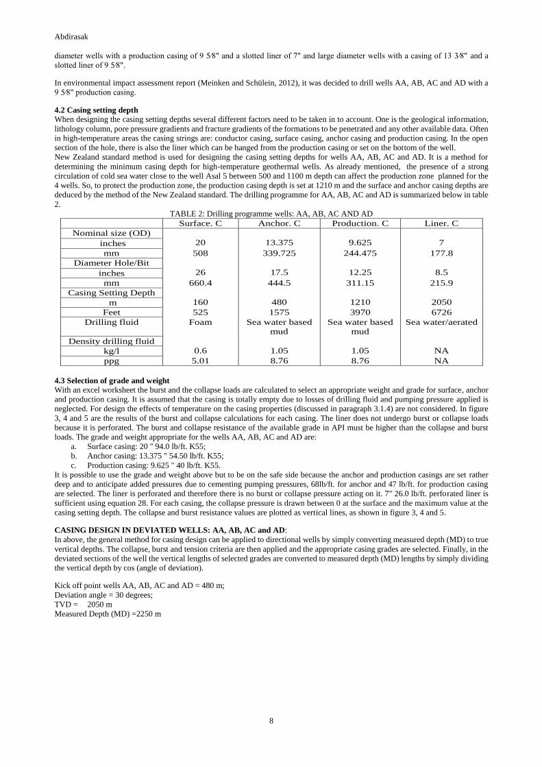
4.2 Casing setting depth
When designing the casing setting depths several different factors need to be taken in to account. One is the geological information,
lithology column, pore pressure gradients and fracture gradients of the formations to be penetrated and any other available data. Often
in high-temperature areas the casing strings are: conductor casing, surface casing, anchor casing and production casing. In the open
section of the hole, there is also the liner which can be hanged from the production casing or set on the bottom of the well.
New Zealand standard method is used for designing the casing setting depths for wells AA, AB, AC and AD. It is a method for
determining the minimum casing depth for high-temperature geothermal wells. As already mentioned, the presence of a strong
circulation of cold sea water close to the well Asal 5 between 500 and 1100 m depth can affect the production zone planned for the
4 wells. So, to protect the production zone, the production casing depth is set at 1210 m and the surface and anchor casing depths are
deduced by the method of the New Zealand standard. The drilling programme for AA, AB, AC and AD is summarized below in table
2.
TABLE 2: Drilling programme wells: AA, AB, AC AND AD
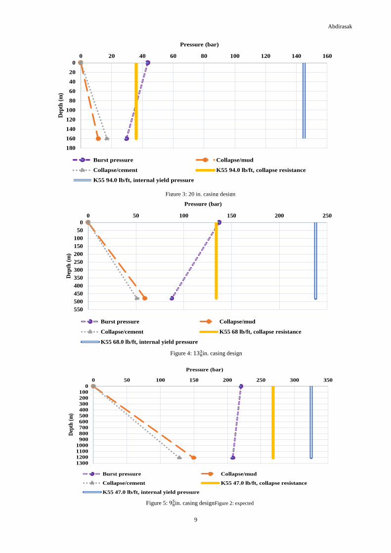
4.3 Selection of grade and weight
With an excel worksheet the burst and the collapse loads are calculated to select an appropriate weight and grade for surface, anchor
and production casing. It is assumed that the casing is totally empty due to losses of drilling fluid and pumping pressure applied is
neglected. For design the effects of temperature on the casing properties (discussed in paragraph 3.1.4) are not considered. In figure
3, 4 and 5 are the results of the burst and collapse calculations for each casing. The liner does not undergo burst or collapse loads
because it is perforated. The burst and collapse resistance of the available grade in API must be higher than the collapse and burst
loads. The grade and weight appropriate for the wells AA, AB, AC and AD are:
a. Surface casing: 20 " 94.0 lb/ft. K55;
b. Anchor casing: 13.375 " 54.50 lb/ft. K55;
c. Production casing: 9.625 " 40 lb/ft. K55.
It is possible to use the grade and weight above but to be on the safe side because the anchor and production casings are set rather
deep and to anticipate added pressures due to cementing pumping pressures, 68lb/ft. for anchor and 47 lb/ft. for production casing
are selected. The liner is perforated and therefore there is no burst or collapse pressure acting on it. 7" 26.0 lb/ft. perforated liner is
sufficient using equation 28. For each casing, the collapse pressure is drawn between 0 at the surface and the maximum value at the
casing setting depth. The collapse and burst resistance values are plotted as vertical lines, as shown in figure 3, 4 and 5.
CASING DESIGN IN DEVIATED WELLS: AA, AB, AC and AD:
In above, the general method for casing design can be applied to directional wells by simply converting measured depth (MD) to true
vertical depths. The collapse, burst and tension criteria are then applied and the appropriate casing grades are selected. Finally, in the
deviated sections of the well the vertical lengths of selected grades are converted to measured depth (MD) lengths by simply dividing
the vertical depth by cos (angle of deviation).
Kick off point wells AA, AB, AC and AD = 480 m;
Deviation angle = 30 degrees;
TVD = 2050 m
Measured Depth (MD) =2250 m
Surface. C Anchor. C Production. C Liner. C
Nominal size (OD)
20
13.375
9.625
7 inches
mm 508 339.725 244.475 177.8
Diameter Hole/Bit
26
17.5
12.25
8.5 inches
mm 660.4 444.5 311.15 215.9
Casing Setting Depth
160
480
1210
2050 m
Feet 525 1575 3970 6726
Drilling fluid Foam Sea water based
mud
Sea water based
mud
Sea water/aerated
Density drilling fluid
0.6
1.05
1.05
NA kg/l
ppg 5.01 8.76 8.76 NA
Abdirasak
9
Figure 3: 20 in. casing design
0
20
40
60
80
100
120
140
160
180
0 20 40 60 80 100 120 140 160D
epth
(m
)
Pressure (bar)
Burst pressure Collapse/mud
Collapse/cement K55 94.0 lb/ft, collapse resistance
K55 94.0 lb/ft, internal yield pressure
Figure 4: 1383in. casing design
0
50
100
150
200
250
300
350
400
450
500
550
0 50 100 150 200 250
Dep
th (
m)
Pressure (bar)
Burst pressure Collapse/mud
Collapse/cement K55 68 lb/ft, collapse resistance
K55 68.0 lb/ft, internal yield pressure
Figure 5: 985in. casing designFigure 2: expected
0
100
200
300
400
500
600
700
800
900
1000
1100
1200
1300
0 50 100 150 200 250 300 350
Dep
th (
m)
Pressure (bar)
Burst pressure Collapse/mud
Collapse/cement K55 47.0 lb/ft, collapse resistance
K55 47.0 lb/ft, internal yield pressure

Abdirasak
10
The selection of grade and weight provides the basis for checking for tension. The tensile loads are to be included in the design of
the casings string. Table 3 below is determined the total tensile and the safety factor for each section. To assure that the safety factor
for tension loads are equal or above 1.5 – 1.8. The entire volume of cement is outside the casing and the casing inside is full of
displacement fluid. When the casing is cemented, the effects of shock loading is disappear, therefore the safety factor in tension 1.4
in production section can be tolerated.
TABLE 3: Tensile loads
Table 4: Compressive loads due to thermal expansion during heating-up
Surface casing Anchor casing Production casing
Compressive loads in
1000daN
156
352
508
To do biaxial correction, I resolve an equation with the VIKING ENGINEERING programme for reducing the collapse rating in the
presence of axial tension. The collapse resistance of casing in the presence of an axial stress is calculated by reducing the yield
strength in accordance to the axial stress:
SURFACE CASING: 20 " 94.0 lb/ft. K55:
Axial stress = 1599.5 psi
Reduced Yield Strength due to axial stress: 54.2 ksi
Reduced Collapse pressure: 520 psi
ANCHOR CASING: 13.375 " 68.0 lb/ft. K55:
Axial stress = 4804.4 psi
Reduced Yield Strength due to axial stress: 52.4 ksi
Reduced Collapse pressure: 1900 psi
PRODUCTION CASING: 9.625 " 47 lb/ft. K55:
Axial stress = 11096 psi
Reduced Yield Strength due to axial stress: 48.6 ksi
Reduced Collapse pressure: 3600 psi
5. CEMENTING PROCESS
The casing of a wells AA, AB, AC, and AD will be cemented in place with a single stage cementing operation with a cementing head
(single stage cementing). The single stage procedure follows the following steps:
a. Installation of the cementing head,
b. Cleaning out the mud in the annulus,
c. Release wiper plug, to clean the inside of the casing and to maintain the spacer front,
d. Pump spacer into the casing,
e. Pump cement,
f. Release shut-off plug
g. Stop the displacement process, when the plug reaches the float collar
All casings are fully cemented back to the surface. For each casing the total slurry volume is the sum of four volumes: slurry volume
between the casing and the open hole, slurry volume left inside the casing below the float collar, slurry volume in the rathole and
slurry volume in the annulus between the casing and the previous casing (see figure). The duration of the operation can be calculated
using, a displacement rate of 24 l/s and mixing and pumping rate of 20 l/s (Thórhallsson, S., 2013).
Table 5: Total slurry and duration
Surface casing Anchor casing Production casing Total
Slurry volume 38.80 m3 49.5 m3 53 m3 141 m3
*Duration of the
cementing operation
113 min
127 min
139 min
379 min
Selected
Grade and
Weight
Max.
buoyant
Weight in
1000daN
Bending
force in
1000daN
Shock
load in
1000daN
Lifting force due to
wellhead pressure in
1000daN
Force due to
pressure
testing in
1000daN
Total
tensile in
1000daN
Safety
factor
Surface casing
20" 94.0 lb/ft.
K55
19.2 133.8
161.3 314.1 2.1
Anchor casing
13.375" 68.0
lb/ft. K55
41.6
96.8
36.4
125.84
300.2
1.6
Production
casing
9.625" 47.0
lb/ft. K55
72.5
31.71
66.9
68.8
239.9
1.4

Abdirasak
11
*The duration of the cementing operation is given by:
Duration =
Slurry volume
pumping and mixing rate+
displacement volume
displacement rate+ contigency(1hr) (46)
6. WELLHEAD DESIGN
Wellheads includes several pieces of equipment: the most important is the master valve which is used to isolate the well. Other
equipment include casing head flange, gaskets, bolts, kill valves and the expansion spool. Typical permanent wellhead can be seen
in figure 7. Wellhead pressure (WHP) can be proportional to the reservoir pressure, when the reservoir pressure is high, the wellhead
pressure (WHP) will likely also be high. The phases of the fluid at the wellhead varies, it can be in different phases: saturated water,
saturated steam or it can be gas the accumulates in the well when its shut in. The surface conditions cannot assimilate to the bottom
values, but in some cases they may be an approach. The different wellhead components should be designed to withstand the maximum
pressure and temperature exposure under static and flowing conditions. The wellhead should be designed according to the codes of
practice. The master valve is often chosen by using pressure ratings of flanges conforming to ANSI b16.5 and to API 6A (Hole,
1996). The top section of the anchor casing, from surface to around 25 m depth should also comply with ASME B31.1 Power piping
code.
WELLHEAD PRESSURE ESTIMATE AND THE CLASS:
The wellhead pressure is calculated using the density of the saturated liquid for the calculation of the hydrostatic pressure and the
density of saturated steam for the calculation of the pressure of the steam column in the production section back to the surface to the
wellhead. First the hydrostatic pressure is calculated from 200 m (water level) to the bottom of the well at 2000 m at every 50 meters.
Secondly, the boiling point (1100 m) is determined. From this point the pressure of the steam column in the production section and
to the surface to the wellhead is calculated. The class of the wellhead shall be API 3000, it is chosen by using pressure ratings of
flanges conforming to ANSI b16.5 and to API 6A (figure 6 below).
Figure 6: Pressure rating of wellhead

Abdirasak
12
7. CONCLUSIONS
The casing programme is vital to the success and safety of the well drilling process and to the integrity and life of the well. The design
of wells AA, AB, AC and AD are oversized for to avoid any risk. After the drilling of the first well, the first useful geotechnical data
for the new drilling site will be available, therefore the design of the three other wells will be optimized. Generally, drilling can be
done with foam or mud. The choice of drilling fluid will depend on the geology and the surrounding terrain. In the Fiale area, it is
most likely that the drilling fluid used will consist of seawater based drilling mud. But in the production section using aerated drilling
should be considered because of possible low permeability.
REFERENCES
Aquater, 1989: Asal 5 well report - final report, Aquater, Italy, report, 64 pp.
Árnason, K., Björnsson, G., Flóvenz, Ó.G., Harldsson, E.H., 1988: Geothermal resistivity survey in the Asal rift, volume 1: Main text.
Orkustofnun, Reykjavík, prepared for the UND-OPS and ISERST, OS-88031/JHD-05, 48 pp.
Baker Hughes INTEQ, 1995: Drilling engineering workbook. A distributed learning course. Baker Hughes INTEQ Inc., 410 pp.
Bett, E.K., 2010: Geothermal well cementing, materials and placement techniques. Report 10 in: Geothermal training in Iceland
2010. UNU-GTP, Iceland, 99-130.
BG Group, 2001: Well engineering and production operations management system. B.G. Group, casing design manual, vs. 2.
Devereux, S., 1998: Practical well planning and drilling. Pennwell, Oklahoma, Ok, 524 pp.
Elmi H., D., 2005: Analysis of geothermal well test data from the Asal rift area, Republic of Djibouti. Report 6 in: Geothermal
training in Iceland 2005. UNU-GTP, Iceland, 39-59.
Gabolde G., and Nguyen, J.P., 2006: Drilling data handbook (8th edition). Institut Française du Petrole Publications, Paris, 552 pp.
Heriot-Watt University, 2010: Drilling engineering. Heriot-Watt University, Department of petroleum engineering, 539 pp.
Hole, H.M., 1996: Geothermal Energy New Zealand, Ltd. Seminar on Geothermal Drilling Engineering, Jakarta, Indonesia, March,
Seminar handbook.
Hossein-Pourazad, H., 2005: High-temperature geothermal well design. Report 9 in: Geothermal training in Iceland 2005. UNU-
GTP, Iceland, 111-123.
Jalludin, M., 2010: State of knowledge of the geothermal provinces of the Republic of Djibouti. Paper presented at “Short Course
V on Exploration for Geothermal Resources” organized by UNU-GTP, KenGen and GDC, Lake Naivasha, Kenya, 14 pp.
Khaireh, A.E., 1989: Borehole geology of well Asal-5, Asal geothermal field, Djibouti. UNU-GTP, Iceland, report 6, 31 pp.
Meinken, W., and Schülein, S., 2012: Geothermal resources evaluation project Djibouti, environmental and social impacts. Fichtner
GmbH and Co., final report, 14 pp.
NZS, 1991: Code of practice for deep geothermal wells. New Zealand standards 2403, Standards Association of New Zealand.
Rabia, H., 1987: Fundamentals of casing design, vol. 1. Petroleum Engineering and Development Studies.
REI, 2008: Drilling and testing of geothermal exploration wells in the Assal area, Djibouti: Environmental management plan.
Reykjavik Energy Invest, report REI-2008/Assal 1, 58 pp.
Saemundsson, K., 1988: Djibouti geothermal project. Analysis of geological data pertaining to geothermal exploration of Asal rift.
UNDP, 18 pp.
Stiltjes, L., 1976: Research for a geothermal field in a zone of oceanic spreading: Examples of the Asal
Rift. Proceedings of the 2nd UN Symposium on the Development and Use of Geothermal Resources, San Francisco, Ca, 1, 613-623.
Thórhallsson, S., 2013: Geothermal drilling technology. UNU-GTP, Iceland, unpublished lecture notes.
Varet, J., 1978. Geology of central and southern Afar (Ethiopia and Djibouti Republic). In: Gasse, F. (ed.), CNRS, Paris, 118.
Virkir-Orkint, 1990: Djibouti, geothermal scaling and corrosion study. Virkir-Orkint, Reykjavík, report, 109 pp.
Figure 7: typical completion wellhead