Embed Size (px)
Citation preview
GEOTHERM INC.
COOL SOLUTIONS FOR UNDERGROUND POWER CABLES
THERMAL SURVEYS, CORRECTIVE BACKFILLS & INSTRUMENTATION
Serving the electric power industry since 1978
P.O. Box 742
Aurora, Ontario
CANADA L4G 4J9
Tel: 905-727-6448
Fax: 905-727-4325
email: [email protected]
SOIL THERMAL SURVEY
LUTHER FOREST TECHNICAL CAMPUS 115 kV UNDERGROUND CABLES
MALTA, NEW YORK SEPTEMBER 2008
Prepared for:
TRC,
225 Greenfield Parkway, Suite 203 Liverpool, NY 13088
Submitted by:
GEOTHERM INC.
GEOTHERM INC.
1
P.O. Box 742
Aurora, Ontario
CANADA L4G 4J9
Tel: 905-727-6448
Fax: 905-727-4325
email: [email protected]
SOIL THERMAL SURVEY LUTHER FOREST TECHNICAL CAMPUS
115 kV UNDERGROUND CABLES MALTA, NEW YORK
SEPTEMBER 2008
INTRODUCTION A field thermal resistivity survey of the native soils was performed for the proposed 115kV underground transmission line from the Malta Substation to the Stonebreak Road Terminal in Malta, New York. Thermal resistivity testing was carried out to a depth of about 10 feet at 9 locations as selected and marked by the client. The fieldwork was carried out from the 4
th to the 5
th of September 2008.
SJB Services Inc. provided the soil drilling rig and technical services, as well as obtaining permits and clearing underground services. MEASUREMENT OF THERMAL RESISTIVITY The soil thermal resistivity is a significant component of the total thermal resistance that is used to calculate the ampacity rating of an underground cable. In order to maintain the cable design ampacity and safe operating temperatures, the heat generated by the cable must be dissipated through the soil. The thermal resistivity or rho [°C-cm/W] is a measure of the resistance to heat flow through a unit area of soil, and is measured by the 'transient thermal probe' technique. Basically, a slender cylindrical probe, containing a heater and temperature sensor, is inserted into the soil to be tested. Constant power is applied to the heater and the probe temperature-time data is monitored. The thermal resistivity can be calculated from this curve. As long as certain theoretical assumptions and test procedures are met, the technique is equally applicable to small probes (100mm long by 3mm diameter (4 x ⅛ inches)) in laboratory soil samples and large probes (2m long by 25mm diameter (6 feet x 1 inch)) installed in-situ. The TPA-2000 (EPRI EL-2128), manufactured by Geotherm Inc., is a system that fully automates the thermal probe test. It is computer controlled and provides programmable power to the thermal probes, reads temperature sensors and heater current and voltage, and immediately computes the thermal resistivity. The unit consists of a programmable 1 amp, 50 volt power supply, a 9 channel data acquisition system, and a notebook computer, run off a nominal 110 VAC power source. The entire test procedure is software controlled in an interactive manner and various built-in error-reducing features ensure that the test complies with the theoretical assumptions. A statistical analysis of data indicates whether an acceptable test has been accomplished. Test data (time, temperature, power) is printed, plotted and stored on disk for future analysis and reference to the results.

GEOTHERM INC.
2
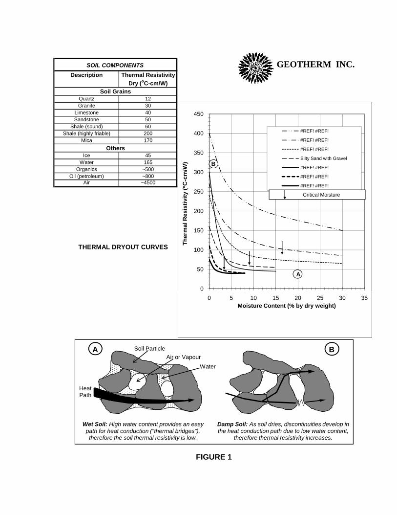
FACTORS AFFECTING THERMAL RESISTIVITY Heat flows through a soil mainly by conduction along mineral particles, and secondarily by conduction and convection through the moisture or air that occupies the pore space between solid particles (Figure 1). Thermal resistivity depends on soil composition and texture, water content, density, and various other factors to a lesser degree. This complex interrelationship does not lend itself to a simple formula, rather a thermal probe test must be carried out on any given soil in an undisturbed condition. Laboratory tests on disturbed soil samples should only be performed when correlated to field test results. Note that once a cable is installed, soil moisture is the only parameter that changes significantly with time. SOIL COMPOSITION: Soil is a composite consisting of solid mineral grains, typically only making point-to-point contact, and pore space filled with water and air. The thermal resistivity of a given soil mass is a function of the intrinsic resistivities of its components. These may range from 12°C-cm/W for quartz mineral, to 40°C-cm/W for limestone, to 165°C-cm/W for water, to about 500°C-cm/W for organics (Figure 1). Even certain highly compacted soils can have up to 30% voids between solid particles, that in a dry state are filled with very high resistivity air (~4500°C-cm/W). TEXTURE: This refers to soil grain size, shape, and particle size gradation. Since most of the heat is conducted through the solid particles and their contacts, the resistivity is minimized for soils that maximize these contacts. In engineering applications, a soil is often qualitatively categorized by a visual description using accepted adjectives (ie. some, little, trace) to indicate the fractional amount of each component (ie. gravel, sand, silt, clay) (see legend for borehole logs). WATER CONTENT: For a given soil the major influence on the thermal resistivity is the moisture content. In a dry state the pore spaces are filled with air (~4500°C-cm/W). As water (~165°C-cm/W) replaces air, the soil resistivity is substantially lowered (as much as 3 to 7 times) as the good heat conduction paths are expanded (‘thermal bridges’). This is illustrated by the 'thermal dryout curve' (thermal resistivity vs. soil moisture content) (Figure 1). A soil that is better able to retain its moisture, as well as being able to efficiently re-wet when dried, will have better thermal performance characteristics. The soil water content is expressed as a percentage of the weight of water to the dry weight of soil solids, as determined by oven drying at 105°C. DRY DENSITY: Soil densification (or compaction) increases mineral grain contacts and displaces air (ie. lowers porosity), therefore reducing the soil resistivity, most notably at low moisture contents. Well-graded soils are potentially more dense because smaller grains can efficiently fill the spaces between the larger particles. Dry density is expressed as the ratio of the dry weight of the soil solids to the total volume. The total volume is taken as the initial volume of the undisturbed moist soil in a sample tube.
GEOTHERM INC.
3
FIELD TESTING AND SAMPLING In total, testing was carried out at 9 locations, as specified by the client, attempting to provide full coverage of the soil conditions. At each test location a truck-mounted auger was used to drill a 4-inch diameter hole to the appropriate depths for the thermal tests (TR). Also soil samples, for density indication and moisture content, were taken at regular intervals in order to establish the soil profile, including enough material for laboratory thermal testing. Disturbed standard split spoon (SPT) samples were taken, as indicated in the borehole logs. In-situ thermal resistivity values were determined at depths of about 3, 7, 9 (and 12) feet using a 200mm long by 6mm diameter (8 x ¼ inch) thermal probe and the Geotherm TPA-2000 run off a portable power source (inverter). The borehole was augered to the appropriate depth and the probe, attached to extension rods, was carefully tapped into undisturbed soil with a small sledgehammer. For good results it is important that the probe is installed with the best possible probe-to-soil contact and minimum disturbance of the native soil. Since the probe generates a heat field in the soil, it is imperative that the probe remains in a stable position for the duration of the test, otherwise the temperature rise in the probe is disrupted, invalidating the test. This time is about 10 to 15 minutes for the small field probes. All thermal testing was performed in accordance with the IEEE Standard (IEEE-442) and ICC guidelines. Field and laboratory geotechnical testing was conducted in accordance with ASTM. The field thermal resistivity values were measured at the given soil moisture on that particular day. Depending on weather and environmental conditions (ie. drying due to cable heat or other heat source (steam mains), seasonal drying (drought), artificial draining, water demand of large trees, drying due to frost (ice lenses), etc.), the soil may be drier at certain times of the year. The design thermal resistivities for the native soils should be chosen at the driest expected conditions. Soil classifications in the borehole logs are made by visual examination of samples. Boundaries between soil layers are considered approximate based upon observed changes during the drilling operation, or based upon examination of representative samples. Test locations are referenced by the ‘borehole number’; exact borehole co-ordinates were determined by SJB Services.
The attached borehole logs present factual information on the subsurface conditions at
the specific test boring locations; no warrantee is expressed or implied that materials or
conditions other than those described may not be encountered along the cable route.

GEOTHERM INC.
4
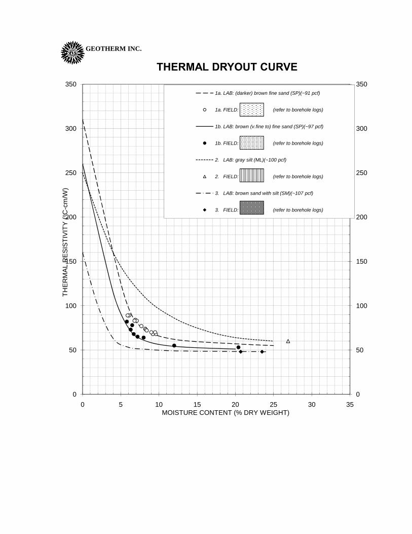
LABORATORY TESTING The laboratory soil descriptions, dry densities, water contents and laboratory thermal resistivities were determined from the retrieved samples, in order to characterize the soils and correlate the field results (see borehole logs and Table 1). Please note that all densities are given as dry densities. Stage drying series were carried out to develop the thermal dryout curves (Figure 2); the field thermal resistivities at the natural moisture contents are also marked. Since only disturbed samples were retrieved, the soil was re-packed into a sample tube at the estimated field density. A small thermal probe was inserted into the soil sample, which was then oven dried in stages. After each drying stage the sample was sealed and allowed to cool and equilibrate with respect to moisture distribution prior to measuring the resistivity. Finally the sample was saturated to get the wet thermal resistivity. At higher soil moistures the thermal dryout curve is relatively flat, indicating that the soil resistivity will not increase much if the soil dries somewhat. At lower moistures, where the curve begins to slope upwards more steeply (ie. below the critical moisture), any amount of soil drying gives rise to a larger increase in the resistivity. At this point the heat from a cable can potentially dry the soil completely (thermal runaway). Thus, if the design resistivity (ie. at the driest expected soil conditions) is in the flat region, the soil resistivity should remain stable under normal cable heat loads. But, if the design value happens to be in the unstable region then the soil can be expected to dry totally near a directly buried cable, and the design must be based on the dry resistivity. Alternatively, for such poor conditions, a concrete ductbank and/or a corrective thermal backfill placed around the cable will reduce the heat flux experienced by the native soil so that it may not dry out. The backfill should be able to better resist total drying, and also have a lower dry resistivity if it is completely dried. Thermal dryout series were run on a total of 10 samples, and three groups of soils with similar thermal behaviour and similar soil description were identified: 1a. Darker brown fine sand (unified soil classification: SP) at a dry density of about 91 pcf. The field thermal resistivity for damp soil was about 70 to 90 °C-cm/W. 1b. Brown (very fine to) fine sand (SP) at about 97 pcf. The field thermal resistivity was about 65 to 80 °C-cm/W. 2. Gray silt (ML) at about 100 pcf with a natural thermal resistivity of about 60°C-cm/W. 3. Brown sand with silt (SM) at about 107 pcf with a natural thermal resistivity of about 50°C-cm/W. Since only bulk samples were available the dry densities were estimated by correlating the resistivities of laboratory packed samples to the field resistivities.

GEOTHERM INC.
5
COMMENTS Figure 2 summarizes the typical curves for the various soil groups. The thermal resistivities can be estimated for similar soils: if the soils are less dense than the typical density, then the resistivity will be higher than for the typical curve, more so at the lower moisture levels; similarly a more dense soil will have a lower resistivity than the typical curve. Figure 3 shows a profile of the thermal resistivities along the route. The thermal dryout curves, along with estimates of the driest expected soil moistures, can be used to determine the design resistivities for the native soils. (Similarly the design resistivity of any corrective backfill that may be placed around the cables can be determined from thermal dryout tests.) The soils are predominantly fine sands. The fine sandy soils (1a.SP) were the driest (6 to 9% moisture) and are the most susceptible for drying out. Under natural conditions, that is, exclusive of cable heat effects, if they should dry to about 6% then the thermal resistivity would approach 100°C-cm/W. (Generally the driest soil conditions are encountered at the end of a hot, dry summer). At less than 8 or 9% moisture the sandy soil would be below the critical moisture content and thermally unstable. That is, if drier soil conditions due to cable heat are expected then the soil resistivity will increase substantially. Without a concrete ductbank and/or corrective thermal backfill the heat from a cable would in all likelihood completely dry out the sandy soil near the cable (300°C-cm/W). Since the cables will be in a concrete ductbank, an analysis may show that the cable heat level at the soil interface would not be excessive. Then the soil near the ductbank may only dry to say 4% moisture with a thermal resistivity of about 150°C-cm/W. In order to provide an additional safety factor for possible greater cable heat effects, a higher value may be chosen as the design thermal resistivity. (For excessive cable heat effects the soil near the ductbank will completely dry out). The denser fine sandy soils (1b.SP) were also quite dry, but the thermal performance is slightly better. At a moisture of 6% the thermal resistivity is about 75°C-cm/W. If they should dry to about 4%, the thermal resistivity would be near 120°C-cm/W. The silty sand (3.SM) and silt (2.ML) soils were quite moist and had much lower thermal resistivities, so even if they should dry substantially, the thermal resistivity would still not exceed 70°C-cm/W. Boreholes #1 and #2 had much moister soil conditions because of a higher groundwater level, therefore the thermal resistivities were quite low. (The true groundwater table should be determined from long term monitoring wells). The remaining boreholes had drier soil conditions.
GEOTHERM INC.
6
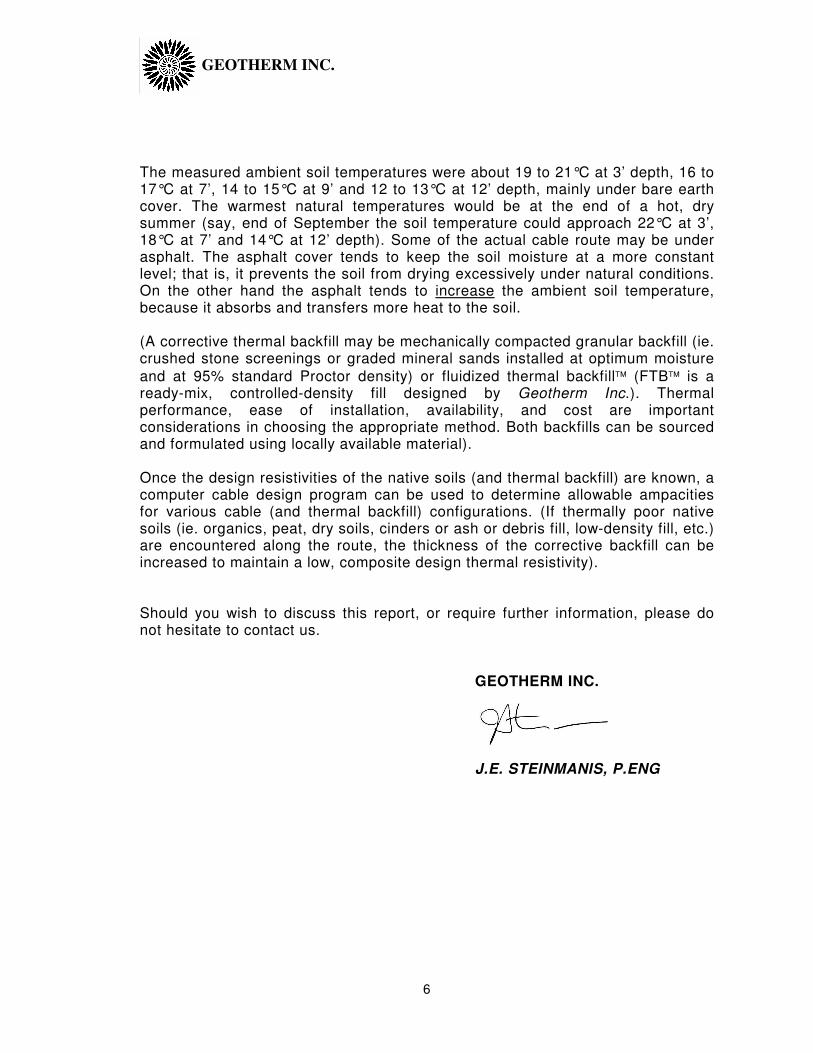
The measured ambient soil temperatures were about 19 to 21°C at 3’ depth, 16 to 17°C at 7’, 14 to 15°C at 9’ and 12 to 13°C at 12’ depth, mainly under bare earth cover. The warmest natural temperatures would be at the end of a hot, dry summer (say, end of September the soil temperature could approach 22°C at 3’, 18°C at 7’ and 14°C at 12’ depth). Some of the actual cable route may be under asphalt. The asphalt cover tends to keep the soil moisture at a more constant level; that is, it prevents the soil from drying excessively under natural conditions. On the other hand the asphalt tends to increase the ambient soil temperature, because it absorbs and transfers more heat to the soil. (A corrective thermal backfill may be mechanically compacted granular backfill (ie. crushed stone screenings or graded mineral sands installed at optimum moisture
and at 95% standard Proctor density) or fluidized thermal backfill (FTB is a ready-mix, controlled-density fill designed by Geotherm Inc.). Thermal performance, ease of installation, availability, and cost are important considerations in choosing the appropriate method. Both backfills can be sourced and formulated using locally available material). Once the design resistivities of the native soils (and thermal backfill) are known, a computer cable design program can be used to determine allowable ampacities for various cable (and thermal backfill) configurations. (If thermally poor native soils (ie. organics, peat, dry soils, cinders or ash or debris fill, low-density fill, etc.) are encountered along the route, the thickness of the corrective backfill can be increased to maintain a low, composite design thermal resistivity). Should you wish to discuss this report, or require further information, please do not hesitate to contact us. GEOTHERM INC. J.E. STEINMANIS, P.ENG

GEOTHERM INC.
7
TABLE 1
LUTHER FOREST TECHNICAL CAMPUS LABORATORY DRYOUT TESTS
SEPTEMBER 2008
#
Soil Description Soil Type
Thermal Resistivity Field (°C-cm/W) Lab
Water Cont.(%)
Dry Dens. (pcf)
2 darker brown fine to med. 3 48 47 20.7 107
9’ sand w/a little silt 160 0
2 gray silt 2 60 59 26.9 100
12’ 250 0
50 22.1
3 brown fine sand 1b 68 70 6.7 97
3’ 270 0
53 23.7
4 dark brown fine sand 1a x 66 9.5 93
8’ 290 0
50 22.3
5 (lighter) brown fine sand 1b x 72 6.4 97
7’ 260 0
49 22.1
7 brown very fine to fine sand 1b x 63 7.9 98
5’ 240 0
52 25.4
7 darker brown fine sand 1a 68 67 9.6 92
9’ 300 0
54 27.4
8 darker brown fine sand 1a 70 68 9.5 91
5’ 305 0
55 26.1
8 darker brown fine sand 1a x 75 7.4 92
7’ 300 0
50 26.1
9 light brown very fine sand 1b x 64 7.5 97
9’ 280 0
GEOTHERM INC.
8
-------------------------------------------------------------------------------------------------------------------------------------
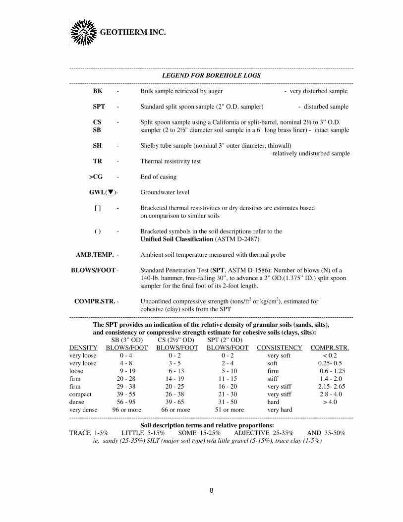
LEGEND FOR BOREHOLE LOGS
-------------------------------------------------------------------------------------------------------------------------------------
BK - Bulk sample retrieved by auger - very disturbed sample
SPT - Standard split spoon sample (2" O.D. sampler) - disturbed sample
CS - Split spoon sample using a California or split-barrel, nominal 2½ to 3” O.D.
SB sampler (2 to 2½" diameter soil sample in a 6" long brass liner) - intact sample
SH - Shelby tube sample (nominal 3" outer diameter, thinwall)
-relatively undisturbed sample
TR - Thermal resistivity test
>CG - End of casing
GWL(�)- Groundwater level
[ ] - Bracketed thermal resistivities or dry densities are estimates based
on comparison to similar soils
( ) - Bracketed symbols in the soil descriptions refer to the
Unified Soil Classification (ASTM D-2487)
AMB.TEMP. - Ambient soil temperature measured with thermal probe
BLOWS/FOOT - Standard Penetration Test (SPT, ASTM D-1586): Number of blows (N) of a
140-lb. hammer, free-falling 30”, to advance a 2” OD.(1.375” ID.) split spoon
sampler for the final foot of its 2-foot length.
COMPR.STR. - Unconfined compressive strength (tons/ft2 or kg/cm
2), estimated for
cohesive (clay) soils from the SPT
-------------------------------------------------------------------------------------------------------------------------------------
The SPT provides an indication of the relative density of granular soils (sands, silts),
and consistency or compressive strength estimate for cohesive soils (clays, silts):
SB (3” OD) CS (2½” OD) SPT (2” OD)
DENSITY BLOWS/FOOT BLOWS/FOOT BLOWS/FOOT CONSISTENCY COMPR.STR.
very loose 0 - 4 0 - 2 0 - 2 very soft < 0.2
very loose 4 - 8 3 - 5 2 - 4 soft 0.25- 0.5
loose 9 - 19 6 - 13 5 - 10 firm 0.6 - 1.25
firm 20 - 28 14 - 19 11 - 15 stiff 1.4 - 2.0
firm 29 - 38 20 - 25 16 - 20 very stiff 2.15- 2.65
compact 39 - 55 26 - 38 21 - 30 very stiff 2.8 - 4.0
dense 56 - 95 39 - 65 31 - 50 hard > 4.0
very dense 96 or more 66 or more 51 or more very hard
-------------------------------------------------------------------------------------------------------------------------------------
Soil description terms and relative proportions:
TRACE 1-5% LITTLE 5-15% SOME 15-25% ADJECTIVE 25-35% AND 35-50%
ie. sandy (25-35%) SILT (major soil type) w/a little gravel (5-15%), trace clay (1-5%)
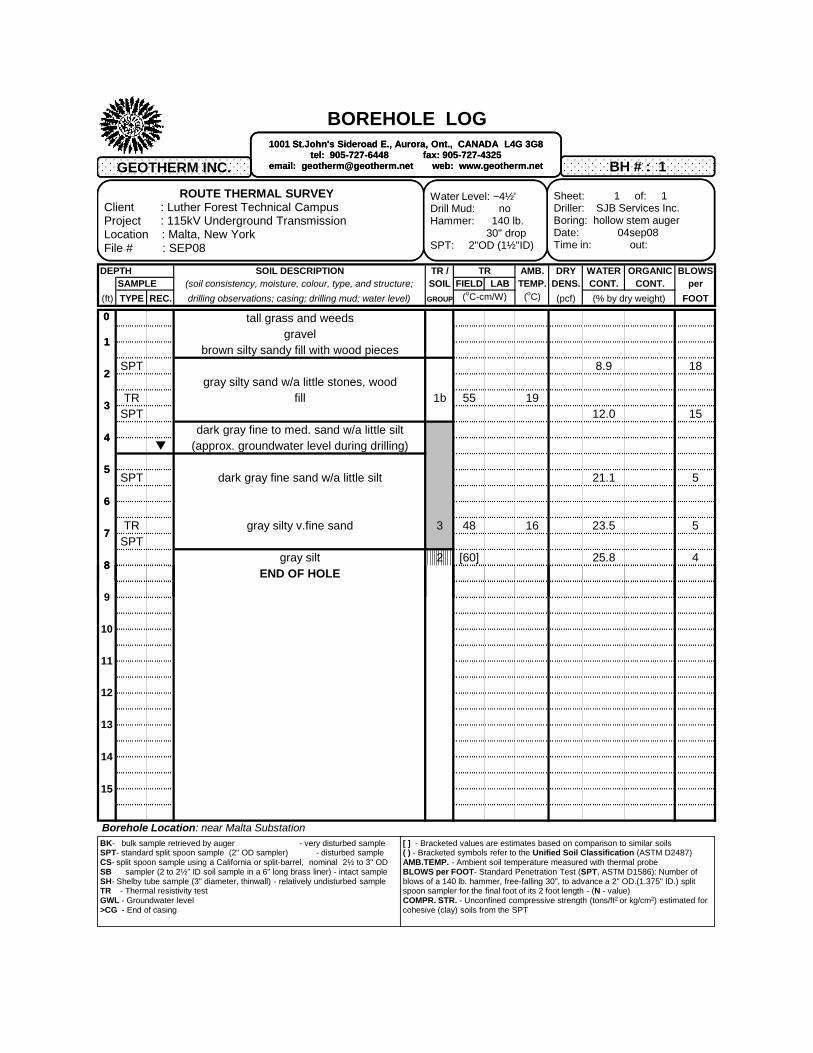
BOREHOLE LOG
DEPTH SOIL DESCRIPTION TR / TR AMB. DRY WATER ORGANIC BLOWSSAMPLE (soil consistency, moisture, colour, type, and structure; SOIL FIELD LAB TEMP. DENS. CONT. CONT. per
(ft) TYPE REC. drilling observations; casing; drilling mud; water level) GROUP (oC-cm/W) (oC) (pcf) (% by dry weight) FOOT
tall grass and weedsgravel
brown silty sandy fill with wood piecesSPT 8.9 18
gray silty sand w/a little stones, woodTR fill 1b 55 19
SPT 12.0 15dark gray fine to med. sand w/a little silt
(approx. groundwater level during drilling)
SPT dark gray fine sand w/a little silt 21.1 5
TR gray silty v.fine sand 3 48 16 23.5 5SPT
gray silt 2 [60] 25.8 4END OF HOLE
ROUTE THERMAL SURVEYClient : Luther Forest Technical CampusProject : 115kV Underground TransmissionLocation : Malta, New YorkFile # : SEP08
BH # : 1
Sheet: 1 of: 1Driller: SJB Services Inc.Boring: hollow stem augerDate: 04sep08Time in: out:
Water Level: ~4½'Drill Mud: noHammer: 140 lb.
30" dropSPT: 2"OD (1½"ID)
1001 St.John's Sideroad E., Aurora, Ont., CANADA L4G 3G8tel: 905-727-6448 fax: 905-727-4325
email: [email protected] web: www.geotherm.net
0
1
2
3
4
5
6
7
8
9
GEOTHERM INC.
ROUTE THERMAL SURVEYClient : Luther Forest Technical CampusProject : 115kV Underground TransmissionLocation : Malta, New YorkFile # : SEP08
BH # : 1
Sheet: 1 of: 1Driller: SJB Services Inc.Boring: hollow stem augerDate: 04sep08Time in: out:
Water Level: ~4½'Drill Mud: noHammer: 140 lb.
30" dropSPT: 2"OD (1½"ID)
BK- bulk sample retrieved by auger - very disturbed sampleSPT- standard split spoon sample (2" OD sampler) - disturbed sampleCS- split spoon sample using a California or split-barrel, nominal 2½ to 3" ODSB sampler (2 to 2½" ID soil sample in a 6" long brass liner) - intact sampleSH- Shelby tube sample (3" diameter, thinwall) - relatively undisturbed sampleTR - Thermal resistivity testGWL - Groundwater level >CG - End of casing
1001 St.John's Sideroad E., Aurora, Ont., CANADA L4G 3G8tel: 905-727-6448 fax: 905-727-4325
email: [email protected] web: www.geotherm.net
[ ] - Bracketed values are estimates based on comparison to similar soils( ) - Bracketed symbols refer to the Unified Soil Classification (ASTM D2487)AMB.TEMP. - Ambient soil temperature measured with thermal probeBLOWS per FOOT- Standard Penetration Test (SPT, ASTM D1586): Number of blows of a 140 lb. hammer, free-falling 30", to advance a 2" OD.(1.375" ID.) split spoon sampler for the final foot of its 2 foot length - (N - value)COMPR. STR. - Unconfined compressive strength (tons/ft2 or kg/cm2) estimated for cohesive (clay) soils from the SPT
Borehole Location: near Malta Substation
0
1
2
3
4
5
6
7
8
9
10
GEOTHERM INC.
11
12
13
14
15

BOREHOLE LOG
DEPTH SOIL DESCRIPTION TR / TR AMB. DRY WATER ORGANIC BLOWSSAMPLE (soil consistency, moisture, colour, type, and structure; SOIL FIELD LAB TEMP. DENS. CONT. CONT. per
(ft) TYPE REC. drilling observations; casing; drilling mud; water level) GROUP (oC-cm/W) (oC) (pcf) (% by dry weight) FOOT
bare earth (graded)
SPT (lighter) brown fine sand 6.6 8
TR 65 17SPT brown fine to med. sand 1b 7.2 5
(approx. groundwater level during drilling)
SPT darker brown fine to med. sand 20.9 4
ROUTE THERMAL SURVEYClient : Luther Forest Technical CampusProject : 115kV Underground TransmissionLocation : Malta, New YorkFile # : SEP08
BH # : 2
Sheet: 1 of: 1Driller: SJB Services Inc.Boring: hollow stem augerDate: 04sep08Time in: out:
Water Level: ~6'Drill Mud: noHammer: 140 lb.
30" dropSPT: 2"OD (1½"ID)
1001 St.John's Sideroad E., Aurora, Ont., CANADA L4G 3G8tel: 905-727-6448 fax: 905-727-4325
email: [email protected] web: www.geotherm.net
0
1
2
3
4
5
6
7
8
9
GEOTHERM INC.
TR 48 14SPT darker brown fine to med. sand w/a little silt 3 47 107 20.7 2
TR gray silt 2 60 12 26.9SPT 59 100 3
blue-gray clay 43.8END OF HOLE
ROUTE THERMAL SURVEYClient : Luther Forest Technical CampusProject : 115kV Underground TransmissionLocation : Malta, New YorkFile # : SEP08
BH # : 2
Sheet: 1 of: 1Driller: SJB Services Inc.Boring: hollow stem augerDate: 04sep08Time in: out:
Water Level: ~6'Drill Mud: noHammer: 140 lb.
30" dropSPT: 2"OD (1½"ID)
BK- bulk sample retrieved by auger - very disturbed sampleSPT- standard split spoon sample (2" OD sampler) - disturbed sampleCS- split spoon sample using a California or split-barrel, nominal 2½ to 3" ODSB sampler (2 to 2½" ID soil sample in a 6" long brass liner) - intact sampleSH- Shelby tube sample (3" diameter, thinwall) - relatively undisturbed sampleTR - Thermal resistivity testGWL - Groundwater level >CG - End of casing
1001 St.John's Sideroad E., Aurora, Ont., CANADA L4G 3G8tel: 905-727-6448 fax: 905-727-4325
email: [email protected] web: www.geotherm.net
[ ] - Bracketed values are estimates based on comparison to similar soils( ) - Bracketed symbols refer to the Unified Soil Classification (ASTM D2487)AMB.TEMP. - Ambient soil temperature measured with thermal probeBLOWS per FOOT- Standard Penetration Test (SPT, ASTM D1586): Number of blows of a 140 lb. hammer, free-falling 30", to advance a 2" OD.(1.375" ID.) split spoon sampler for the final foot of its 2 foot length - (N - value)COMPR. STR. - Unconfined compressive strength (tons/ft2 or kg/cm2) estimated for cohesive (clay) soils from the SPT
Borehole Location:
0
1
2
3
4
5
6
7
8
9
10
GEOTHERM INC.
11
12
13
14
15

BOREHOLE LOG
DEPTH SOIL DESCRIPTION TR / TR AMB. DRY WATER ORGANIC BLOWSSAMPLE (soil consistency, moisture, colour, type, and structure; SOIL FIELD LAB TEMP. DENS. CONT. CONT. per
(ft) TYPE REC. drilling observations; casing; drilling mud; water level) GROUP (oC-cm/W) (oC) (pcf) (% by dry weight) FOOT
bare earth (graded)
SPT lighter brown v.fine to fine sand 10.5 8
TR 68 18SPT brown fine sand 1b 70 97 6.7 6
TR 74 16SPT (darker) brown fine to med. sand 1a 8.3 4
END OF HOLE
ROUTE THERMAL SURVEYClient : Luther Forest Technical CampusProject : 115kV Underground TransmissionLocation : Malta, New YorkFile # : SEP08
BH # : 3
Sheet: 1 of: 1Driller: SJB Services Inc.Boring: hollow stem augerDate: 04sep08Time in: out:
Water Level:Drill Mud: noHammer: 140 lb.
30" dropSPT: 2"OD (1½"ID)
1001 St.John's Sideroad E., Aurora, Ont., CANADA L4G 3G8tel: 905-727-6448 fax: 905-727-4325
email: [email protected] web: www.geotherm.net
0
1
2
3
4
5
6
7
8
9
GEOTHERM INC.
ROUTE THERMAL SURVEYClient : Luther Forest Technical CampusProject : 115kV Underground TransmissionLocation : Malta, New YorkFile # : SEP08
BH # : 3
Sheet: 1 of: 1Driller: SJB Services Inc.Boring: hollow stem augerDate: 04sep08Time in: out:
Water Level:Drill Mud: noHammer: 140 lb.
30" dropSPT: 2"OD (1½"ID)
BK- bulk sample retrieved by auger - very disturbed sampleSPT- standard split spoon sample (2" OD sampler) - disturbed sampleCS- split spoon sample using a California or split-barrel, nominal 2½ to 3" ODSB sampler (2 to 2½" ID soil sample in a 6" long brass liner) - intact sampleSH- Shelby tube sample (3" diameter, thinwall) - relatively undisturbed sampleTR - Thermal resistivity testGWL - Groundwater level >CG - End of casing
1001 St.John's Sideroad E., Aurora, Ont., CANADA L4G 3G8tel: 905-727-6448 fax: 905-727-4325
email: [email protected] web: www.geotherm.net
[ ] - Bracketed values are estimates based on comparison to similar soils( ) - Bracketed symbols refer to the Unified Soil Classification (ASTM D2487)AMB.TEMP. - Ambient soil temperature measured with thermal probeBLOWS per FOOT- Standard Penetration Test (SPT, ASTM D1586): Number of blows of a 140 lb. hammer, free-falling 30", to advance a 2" OD.(1.375" ID.) split spoon sampler for the final foot of its 2 foot length - (N - value)COMPR. STR. - Unconfined compressive strength (tons/ft2 or kg/cm2) estimated for cohesive (clay) soils from the SPT
Borehole Location:
0
1
2
3
4
5
6
7
8
9
10
GEOTHERM INC.
11
12
13
14
15

BOREHOLE LOG
DEPTH SOIL DESCRIPTION TR / TR AMB. DRY WATER ORGANIC BLOWSSAMPLE (soil consistency, moisture, colour, type, and structure; SOIL FIELD LAB TEMP. DENS. CONT. CONT. per
(ft) TYPE REC. drilling observations; casing; drilling mud; water level) GROUP (oC-cm/W) (oC) (pcf) (% by dry weight) FOOT
bare earth (vegetation removed)
SPT lighter brown v.fine to fine sand 11.5 4
TR 73 19SPT brown v.fine sand 1a 8.3 3
SPT brown v.fine sand 11.4 4
TR 84 15 6.9SPT dark brown fine sand 1a 3
66 93 9.5
ROUTE THERMAL SURVEYClient : Luther Forest Technical CampusProject : 115kV Underground TransmissionLocation : Malta, New YorkFile # : SEP08
BH # : 4
Sheet: 1 of: 1Driller: SJB Services Inc.Boring: hollow stem augerDate: 04sep08Time in: out:
Water Level: ~10'Drill Mud: noHammer: 140 lb.
30" dropSPT: 2"OD (1½"ID)
1001 St.John's Sideroad E., Aurora, Ont., CANADA L4G 3G8tel: 905-727-6448 fax: 905-727-4325
email: [email protected] web: www.geotherm.net
0
1
2
3
4
5
6
7
8
9
GEOTHERM INC.
TR brown v.fine sand w/a trace silt 1b 53 12SPT (approx. groundwater level during drilling) 20.4 3
END OF HOLE
ROUTE THERMAL SURVEYClient : Luther Forest Technical CampusProject : 115kV Underground TransmissionLocation : Malta, New YorkFile # : SEP08
BH # : 4
Sheet: 1 of: 1Driller: SJB Services Inc.Boring: hollow stem augerDate: 04sep08Time in: out:
Water Level: ~10'Drill Mud: noHammer: 140 lb.
30" dropSPT: 2"OD (1½"ID)
BK- bulk sample retrieved by auger - very disturbed sampleSPT- standard split spoon sample (2" OD sampler) - disturbed sampleCS- split spoon sample using a California or split-barrel, nominal 2½ to 3" ODSB sampler (2 to 2½" ID soil sample in a 6" long brass liner) - intact sampleSH- Shelby tube sample (3" diameter, thinwall) - relatively undisturbed sampleTR - Thermal resistivity testGWL - Groundwater level >CG - End of casing
1001 St.John's Sideroad E., Aurora, Ont., CANADA L4G 3G8tel: 905-727-6448 fax: 905-727-4325
email: [email protected] web: www.geotherm.net
[ ] - Bracketed values are estimates based on comparison to similar soils( ) - Bracketed symbols refer to the Unified Soil Classification (ASTM D2487)AMB.TEMP. - Ambient soil temperature measured with thermal probeBLOWS per FOOT- Standard Penetration Test (SPT, ASTM D1586): Number of blows of a 140 lb. hammer, free-falling 30", to advance a 2" OD.(1.375" ID.) split spoon sampler for the final foot of its 2 foot length - (N - value)COMPR. STR. - Unconfined compressive strength (tons/ft2 or kg/cm2) estimated for cohesive (clay) soils from the SPT
Borehole Location:
0
1
2
3
4
5
6
7
8
9
10
GEOTHERM INC.
11
12
13
14
15
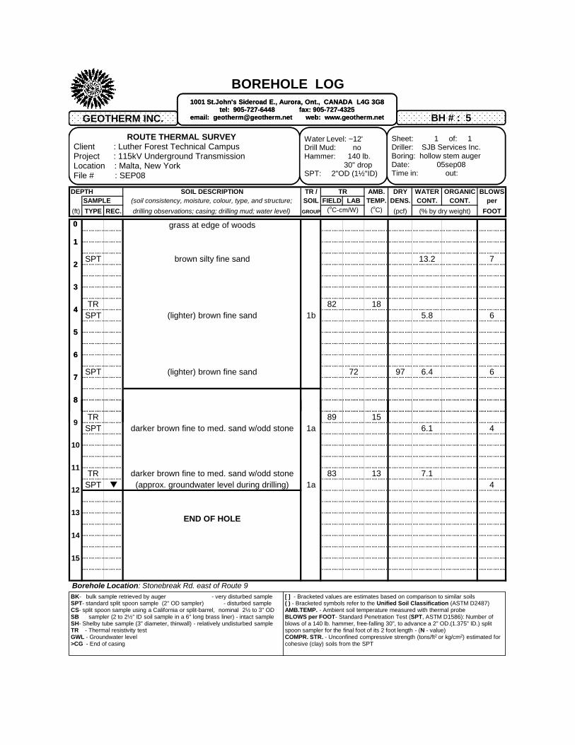
BOREHOLE LOG
DEPTH SOIL DESCRIPTION TR / TR AMB. DRY WATER ORGANIC BLOWSSAMPLE (soil consistency, moisture, colour, type, and structure; SOIL FIELD LAB TEMP. DENS. CONT. CONT. per
(ft) TYPE REC. drilling observations; casing; drilling mud; water level) GROUP (oC-cm/W) (oC) (pcf) (% by dry weight) FOOT
grass at edge of woods
SPT brown silty fine sand 13.2 7
TR 82 18SPT (lighter) brown fine sand 1b 5.8 6
SPT (lighter) brown fine sand 72 97 6.4 6
ROUTE THERMAL SURVEYClient : Luther Forest Technical CampusProject : 115kV Underground TransmissionLocation : Malta, New YorkFile # : SEP08
BH # : 5
Sheet: 1 of: 1Driller: SJB Services Inc.Boring: hollow stem augerDate: 05sep08Time in: out:
Water Level: ~12'Drill Mud: noHammer: 140 lb.
30" dropSPT: 2"OD (1½"ID)
1001 St.John's Sideroad E., Aurora, Ont., CANADA L4G 3G8tel: 905-727-6448 fax: 905-727-4325
email: [email protected] web: www.geotherm.net
0
1
2
3
4
5
6
7
8
9
GEOTHERM INC.
TR 89 15SPT darker brown fine to med. sand w/odd stone 1a 6.1 4
TR darker brown fine to med. sand w/odd stone 83 13 7.1SPT (approx. groundwater level during drilling) 1a 4
END OF HOLE
ROUTE THERMAL SURVEYClient : Luther Forest Technical CampusProject : 115kV Underground TransmissionLocation : Malta, New YorkFile # : SEP08
BH # : 5
Sheet: 1 of: 1Driller: SJB Services Inc.Boring: hollow stem augerDate: 05sep08Time in: out:
Water Level: ~12'Drill Mud: noHammer: 140 lb.
30" dropSPT: 2"OD (1½"ID)
BK- bulk sample retrieved by auger - very disturbed sampleSPT- standard split spoon sample (2" OD sampler) - disturbed sampleCS- split spoon sample using a California or split-barrel, nominal 2½ to 3" ODSB sampler (2 to 2½" ID soil sample in a 6" long brass liner) - intact sampleSH- Shelby tube sample (3" diameter, thinwall) - relatively undisturbed sampleTR - Thermal resistivity testGWL - Groundwater level >CG - End of casing
1001 St.John's Sideroad E., Aurora, Ont., CANADA L4G 3G8tel: 905-727-6448 fax: 905-727-4325
email: [email protected] web: www.geotherm.net
[ ] - Bracketed values are estimates based on comparison to similar soils( ) - Bracketed symbols refer to the Unified Soil Classification (ASTM D2487)AMB.TEMP. - Ambient soil temperature measured with thermal probeBLOWS per FOOT- Standard Penetration Test (SPT, ASTM D1586): Number of blows of a 140 lb. hammer, free-falling 30", to advance a 2" OD.(1.375" ID.) split spoon sampler for the final foot of its 2 foot length - (N - value)COMPR. STR. - Unconfined compressive strength (tons/ft2 or kg/cm2) estimated for cohesive (clay) soils from the SPT
Borehole Location: Stonebreak Rd. east of Route 9
0
1
2
3
4
5
6
7
8
9
10
GEOTHERM INC.
11
12
13
14
15
BOREHOLE LOG
DEPTH SOIL DESCRIPTION TR / TR AMB. DRY WATER ORGANIC BLOWSSAMPLE (soil consistency, moisture, colour, type, and structure; SOIL FIELD LAB TEMP. DENS. CONT. CONT. per
(ft) TYPE REC. drilling observations; casing; drilling mud; water level) GROUP (oC-cm/W) (oC) (pcf) (% by dry weight) FOOT
bare earth (graded)
SPT brown fine sand 5.5 6
TR 72 21SPT brown fine sand 1a 8.4 6
SPT brown v.fine to fine sand 13.5 6
TR 68 17SPT brown fine sand 1a 9.2 8
ROUTE THERMAL SURVEYClient : Luther Forest Technical CampusProject : 115kV Underground TransmissionLocation : Malta, New YorkFile # : SEP08
BH # : 6
Sheet: 1 of: 1Driller: SJB Services Inc.Boring: hollow stem augerDate: 05sep08Time in: out:
Water Level:Drill Mud: noHammer: 140 lb.
30" dropSPT: 2"OD (1½"ID)
1001 St.John's Sideroad E., Aurora, Ont., CANADA L4G 3G8tel: 905-727-6448 fax: 905-727-4325
email: [email protected] web: www.geotherm.net
0
1
2
3
4
5
6
7
8
9
GEOTHERM INC.
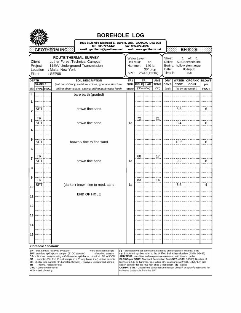
TR 83 14SPT (darker) brown fine to med. sand 1a 6.8 4
END OF HOLE
ROUTE THERMAL SURVEYClient : Luther Forest Technical CampusProject : 115kV Underground TransmissionLocation : Malta, New YorkFile # : SEP08
BH # : 6
Sheet: 1 of: 1Driller: SJB Services Inc.Boring: hollow stem augerDate: 05sep08Time in: out:
Water Level:Drill Mud: noHammer: 140 lb.
30" dropSPT: 2"OD (1½"ID)
BK- bulk sample retrieved by auger - very disturbed sampleSPT- standard split spoon sample (2" OD sampler) - disturbed sampleCS- split spoon sample using a California or split-barrel, nominal 2½ to 3" ODSB sampler (2 to 2½" ID soil sample in a 6" long brass liner) - intact sampleSH- Shelby tube sample (3" diameter, thinwall) - relatively undisturbed sampleTR - Thermal resistivity testGWL - Groundwater level >CG - End of casing
1001 St.John's Sideroad E., Aurora, Ont., CANADA L4G 3G8tel: 905-727-6448 fax: 905-727-4325
email: [email protected] web: www.geotherm.net
[ ] - Bracketed values are estimates based on comparison to similar soils( ) - Bracketed symbols refer to the Unified Soil Classification (ASTM D2487)AMB.TEMP. - Ambient soil temperature measured with thermal probeBLOWS per FOOT- Standard Penetration Test (SPT, ASTM D1586): Number of blows of a 140 lb. hammer, free-falling 30", to advance a 2" OD.(1.375" ID.) split spoon sampler for the final foot of its 2 foot length - (N - value)COMPR. STR. - Unconfined compressive strength (tons/ft2 or kg/cm2) estimated for cohesive (clay) soils from the SPT
Borehole Location:
0
1
2
3
4
5
6
7
8
9
10
GEOTHERM INC.
11
12
13
14
15

BOREHOLE LOG
DEPTH SOIL DESCRIPTION TR / TR AMB. DRY WATER ORGANIC BLOWSSAMPLE (soil consistency, moisture, colour, type, and structure; SOIL FIELD LAB TEMP. DENS. CONT. CONT. per
(ft) TYPE REC. drilling observations; casing; drilling mud; water level) GROUP (oC-cm/W) (oC) (pcf) (% by dry weight) FOOT
bare earth (graded)
SPT lighter brown fine sand 5.5 4
TR 73 21SPT brown v.fine to fine sand 1b 6.3 5
SPT brown v.fine to fine sand 63 98 7.9 7
TR 70 18 9.0SPT darker brown fine sand 1a 6
ROUTE THERMAL SURVEYClient : Luther Forest Technical CampusProject : 115kV Underground TransmissionLocation : Malta, New YorkFile # : SEP08
BH # : 7
Sheet: 1 of: 1Driller: SJB Services Inc.Boring: hollow stem augerDate: 05sep08Time in: out:
Water Level:Drill Mud: noHammer: 140 lb.
30" dropSPT: 2"OD (1½"ID)
1001 St.John's Sideroad E., Aurora, Ont., CANADA L4G 3G8tel: 905-727-6448 fax: 905-727-4325
email: [email protected] web: www.geotherm.net
0
1
2
3
4
5
6
7
8
9
GEOTHERM INC.
TR 68 15 9.6SPT darker brown fine sand 67 92 4
END OF HOLE
ROUTE THERMAL SURVEYClient : Luther Forest Technical CampusProject : 115kV Underground TransmissionLocation : Malta, New YorkFile # : SEP08
BH # : 7
Sheet: 1 of: 1Driller: SJB Services Inc.Boring: hollow stem augerDate: 05sep08Time in: out:
Water Level:Drill Mud: noHammer: 140 lb.
30" dropSPT: 2"OD (1½"ID)
BK- bulk sample retrieved by auger - very disturbed sampleSPT- standard split spoon sample (2" OD sampler) - disturbed sampleCS- split spoon sample using a California or split-barrel, nominal 2½ to 3" ODSB sampler (2 to 2½" ID soil sample in a 6" long brass liner) - intact sampleSH- Shelby tube sample (3" diameter, thinwall) - relatively undisturbed sampleTR - Thermal resistivity testGWL - Groundwater level >CG - End of casing
1001 St.John's Sideroad E., Aurora, Ont., CANADA L4G 3G8tel: 905-727-6448 fax: 905-727-4325
email: [email protected] web: www.geotherm.net
[ ] - Bracketed values are estimates based on comparison to similar soils( ) - Bracketed symbols refer to the Unified Soil Classification (ASTM D2487)AMB.TEMP. - Ambient soil temperature measured with thermal probeBLOWS per FOOT- Standard Penetration Test (SPT, ASTM D1586): Number of blows of a 140 lb. hammer, free-falling 30", to advance a 2" OD.(1.375" ID.) split spoon sampler for the final foot of its 2 foot length - (N - value)COMPR. STR. - Unconfined compressive strength (tons/ft2 or kg/cm2) estimated for cohesive (clay) soils from the SPT
Borehole Location:
0
1
2
3
4
5
6
7
8
9
10
GEOTHERM INC.
11
12
13
14
15

BOREHOLE LOG
DEPTH SOIL DESCRIPTION TR / TR AMB. DRY WATER ORGANIC BLOWSSAMPLE (soil consistency, moisture, colour, type, and structure; SOIL FIELD LAB TEMP. DENS. CONT. CONT. per
(ft) TYPE REC. drilling observations; casing; drilling mud; water level) GROUP (oC-cm/W) (oC) (pcf) (% by dry weight) FOOT
bare earth (graded) Present ground level may not be the final grade.
Surface may be ~2' below concrete manholes.
SPT darker brown fine sand 5.6 2
TR 77 21SPT darker brown fine sand 1a 7.7 3
TR 70 18SPT darker brown fine sand 1a 68 91 9.5 4
SPT darker brown fine sand 75 92 7.4 4
ROUTE THERMAL SURVEYClient : Luther Forest Technical CampusProject : 115kV Underground TransmissionLocation : Malta, New YorkFile # : SEP08
BH # : 8
Sheet: 1 of: 1Driller: SJB Services Inc.Boring: hollow stem augerDate: 05sep08Time in: out:
Water Level:Drill Mud: noHammer: 140 lb.
30" dropSPT: 2"OD (1½"ID)
1001 St.John's Sideroad E., Aurora, Ont., CANADA L4G 3G8tel: 905-727-6448 fax: 905-727-4325
email: [email protected] web: www.geotherm.net
0
1
2
3
4
5
6
7
8
9
GEOTHERM INC.
TR 89 15SPT darker brown fine sand 1a 5.9 5
END OF HOLE
ROUTE THERMAL SURVEYClient : Luther Forest Technical CampusProject : 115kV Underground TransmissionLocation : Malta, New YorkFile # : SEP08
BH # : 8
Sheet: 1 of: 1Driller: SJB Services Inc.Boring: hollow stem augerDate: 05sep08Time in: out:
Water Level:Drill Mud: noHammer: 140 lb.
30" dropSPT: 2"OD (1½"ID)
BK- bulk sample retrieved by auger - very disturbed sampleSPT- standard split spoon sample (2" OD sampler) - disturbed sampleCS- split spoon sample using a California or split-barrel, nominal 2½ to 3" ODSB sampler (2 to 2½" ID soil sample in a 6" long brass liner) - intact sampleSH- Shelby tube sample (3" diameter, thinwall) - relatively undisturbed sampleTR - Thermal resistivity testGWL - Groundwater level >CG - End of casing
1001 St.John's Sideroad E., Aurora, Ont., CANADA L4G 3G8tel: 905-727-6448 fax: 905-727-4325
email: [email protected] web: www.geotherm.net
[ ] - Bracketed values are estimates based on comparison to similar soils( ) - Bracketed symbols refer to the Unified Soil Classification (ASTM D2487)AMB.TEMP. - Ambient soil temperature measured with thermal probeBLOWS per FOOT- Standard Penetration Test (SPT, ASTM D1586): Number of blows of a 140 lb. hammer, free-falling 30", to advance a 2" OD.(1.375" ID.) split spoon sampler for the final foot of its 2 foot length - (N - value)COMPR. STR. - Unconfined compressive strength (tons/ft2 or kg/cm2) estimated for cohesive (clay) soils from the SPT
Borehole Location:
0
1
2
3
4
5
6
7
8
9
10
GEOTHERM INC.
11
12
13
14
15

BOREHOLE LOG
DEPTH SOIL DESCRIPTION TR / TR AMB. DRY WATER ORGANIC BLOWSSAMPLE (soil consistency, moisture, colour, type, and structure; SOIL FIELD LAB TEMP. DENS. CONT. CONT. per
(ft) TYPE REC. drilling observations; casing; drilling mud; water level) GROUP (oC-cm/W) (oC) (pcf) (% by dry weight) FOOT
bare earth (graded) Present ground level may not be the final grade.
SPT light brown v.fine sand 5.3 7
TR 78 21SPT light brown v.fine sand 1b 6.5 7
TR 64 19 8.0SPT light brown v.fine sand 1b 6
8.9
SPT light brown v.fine sand 6.7 10
ROUTE THERMAL SURVEYClient : Luther Forest Technical CampusProject : 115kV Underground TransmissionLocation : Malta, New YorkFile # : SEP08
BH # : 9
Sheet: 1 of: 1Driller: SJB Services Inc.Boring: hollow stem augerDate: 05sep08Time in: out:
Water Level:Drill Mud: noHammer: 140 lb.
30" dropSPT: 2"OD (1½"ID)
1001 St.John's Sideroad E., Aurora, Ont., CANADA L4G 3G8tel: 905-727-6448 fax: 905-727-4325
email: [email protected] web: www.geotherm.net
0
1
2
3
4
5
6
7
8
9
GEOTHERM INC.
TR xSPT light brown v.fine sand 1b 64 97 7.5 10
END OF HOLE
ROUTE THERMAL SURVEYClient : Luther Forest Technical CampusProject : 115kV Underground TransmissionLocation : Malta, New YorkFile # : SEP08
BH # : 9
Sheet: 1 of: 1Driller: SJB Services Inc.Boring: hollow stem augerDate: 05sep08Time in: out:
Water Level:Drill Mud: noHammer: 140 lb.
30" dropSPT: 2"OD (1½"ID)
BK- bulk sample retrieved by auger - very disturbed sampleSPT- standard split spoon sample (2" OD sampler) - disturbed sampleCS- split spoon sample using a California or split-barrel, nominal 2½ to 3" ODSB sampler (2 to 2½" ID soil sample in a 6" long brass liner) - intact sampleSH- Shelby tube sample (3" diameter, thinwall) - relatively undisturbed sampleTR - Thermal resistivity testGWL - Groundwater level >CG - End of casing
1001 St.John's Sideroad E., Aurora, Ont., CANADA L4G 3G8tel: 905-727-6448 fax: 905-727-4325
email: [email protected] web: www.geotherm.net
[ ] - Bracketed values are estimates based on comparison to similar soils( ) - Bracketed symbols refer to the Unified Soil Classification (ASTM D2487)AMB.TEMP. - Ambient soil temperature measured with thermal probeBLOWS per FOOT- Standard Penetration Test (SPT, ASTM D1586): Number of blows of a 140 lb. hammer, free-falling 30", to advance a 2" OD.(1.375" ID.) split spoon sampler for the final foot of its 2 foot length - (N - value)COMPR. STR. - Unconfined compressive strength (tons/ft2 or kg/cm2) estimated for cohesive (clay) soils from the SPT
Borehole Location: at site of Stonebreak Rd. Terminal
0
1
2
3
4
5
6
7
8
9
10
GEOTHERM INC.
11
12
13
14
15
SOIL COMPONENTS GEOTHERM INC.Description Thermal Resistivity
Dry (oC-cm/W)
Soil GrainsQuartz 12Granite 30
Limestone 40Sandstone 50
Shale (sound) 60Shale (highly friable) 200
Mica 170
OthersIce 45
Water 165Organics ~500
Oil (petroleum) ~800Air ~4500
THERMAL DRYOUT CURVES
0
50
100
150
200
250
300
350
400
450
Th
erm
al R
es
isti
vity
(oC
-cm
/W)
#REF! #REF!
#REF! #REF!
#REF! #REF!
Silty Sand with Gravel
#REF! #REF!
#REF! #REF!
#REF! #REF!
B
A
Critical Moisture
FIGURE 1
Soil Particle
Air or Vapour
Water
A B
Wet Soil: High water content provides an easy path for heat conduction ("thermal bridges"), therefore the soil thermal resistivity is low.
Damp Soil: As soil dries, discontinuities develop in the heat conduction path due to low water content,
therefore thermal resistivity increases.
Heat Path
0
50
100
150
200
250
300
350
400
450
0 5 10 15 20 25 30 35
Th
erm
al R
es
isti
vity
(oC
-cm
/W)
Moisture Content (% by dry weight)
#REF! #REF!
#REF! #REF!
#REF! #REF!
Silty Sand with Gravel
#REF! #REF!
#REF! #REF!
#REF! #REF!
B
A
Critical Moisture
GEOTHERM INC.
150
200
250
300
350
150
200
250
300
350
ER
MA
L R
ES
IST
IVIT
Y (
o C-c
m/W
)THERMAL DRYOUT CURVE
1a. LAB: (darker) brown fine sand (SP)(~91 pcf)
1a. FIELD: (refer to borehole logs)
1b. LAB: brown (v.fine to) fine sand (SP)(~97 pcf)
1b. FIELD: (refer to borehole logs)
2. LAB: gray silt (ML)(~100 pcf)
2. FIELD: (refer to borehole logs)
3. LAB: brown sand with silt (SM)(~107 pcf)
3. FIELD: (refer to borehole logs)
0
50
100
0
50
100
0 5 10 15 20 25 30 35
TH
MOISTURE CONTENT (% DRY WEIGHT)
�
� �
�
�

GEOTHERM INC.
50
100
ER
MA
L R
ES
IST
IVIT
Y (
0 C-c
m/W
)
ROUTE THERMAL RESISTIVITY PROFILE borehole location not to scale
0
0 5 10
FIE
LD T
H
BOREHOLE #
~3' depth ~7' depth
~9' depth ~12' depth
�
�
�
�
�
�